Embed Size (px)
Citation preview

ISSN (Online) 2456-1290
International Journal of Engineering Research in Mechanical and Civil Engineering
(IJERMCE)
Vol 2, Issue 10, October 2017
All Rights Reserved © 2017 IJERMCE 38
Design, Modeling, FEM & Experimental Analysis
of Crankshaft and Camshaft of a Passenger Car [1]
Ketan V. Karandikar, [2]
Shailesh P. Deshpande, [3]
Sachin N. Patil, [4]
Sagar A. Deshpande, [5]
Rajendra D.
Ronge
Abstract: -- A crankshaft can be called as the heart of any I.C. engine since it is the first recipient of the power generated by the
engine. Its main function is to convert the oscillating motion of the connecting rod into rotary motion of the flywheel. The main
function of a camshaft is to convert rotary motion of the crankshaft into vertically reciprocating motion of the valves required to
open and close the intake and exhaust valves of engine cylinders, with the assistance of cams located on it and an intermediate
mechanism. The crankshaft is subjected to bending stress and torsional shear stress, whereas the camshaft is mainly subjected to
compressive stress due to contact pressure, galling and wear and tear. This project aims at designing of I.C. engine multi-
crankshaft and camshaft using standard design procedures. Further, Creo software is used to create 3-D models of crankshaft and
camshaft. After creating the models, static structural analysis is performed for both of these using different materials and
boundary conditions using ANSYS software. A static load testing is performed on the crankshaft and camshaft of a TATA Vista
Quadrajet car using UTM and experimental stresses are compared with analytical stresses for validation purpose. Finally, the
results of total deformation and equivalent (von-Mises) stresses obtained for different crankshaft materials like ASTM 100-70-03,
GS-70, AISI 1045 and Inconel X-750, different camshaft materials like ASTM A532 and ASTM A536 are evaluated and compared
with each other to select the best suitable material for manufacturing of crankshaft and camshaft.
Index Terms— ANSYS workbench, crankshaft, camshaft, Creo, design, experimentation, finite element method, materials,
modeling, static loading, stress analysis.
1. INTRODUCTION
A crankshaft as shown in Fig. 1 can be considered as the
heart of an I.C. engine, without which it cannot work. It
allows the pistons to continuously reciprocate inside the
cylinder by means of the unbalanced masses called crank
webs. It has a intricate solid geometry. The crankshaft
consists of three main parts namely the crank pin, crank web
and shaft. The big end of the connecting rod is connected
to the crank pin; the crank web connects the crank pin to the
shaft portion which is rotated by the main bearings and
transmits power to the outside source through the belt drive,
gear drive or chain drive. Load of the gas forces inside the
combustion chamber is transferred and distributed over each
crank pin through the connecting rod. Every crank web is
subjected to bending moment and twisting moment. There is
a flywheel attached at the end of the crankshaft to bring
uniformity in torque of a four-stroke I.C. engine by storing
energy during the power stroke and releasing the same during
the other three strokes. The crankshaft should have
sufficiently high strength so as to sustain the gas force acting
vertically downwards during the expansion stroke. Strength
of the crankshaft should be high enough to avoid bending
failure. Hence, the crankshaft greatly affects the life and
reliability of an I.C. engine. The mechanical arrangement of a
crankshaft in an I.C. engine is as shown in Fig. 2.
Fig. 1 Nomenclature of Crankshaft

ISSN (Online) 2456-1290
International Journal of Engineering Research in Mechanical and Civil Engineering
(IJERMCE)
Vol 2, Issue 10, October 2017
All Rights Reserved © 2017 IJERMCE 39
Fig. 2 Mechanical Arrangement of Crankshaft of a
4-Cylinder I.C. Engine
Cam is a mechanical member having a lobe shape used to
transfer a desired motion to a follower by means of direct
contact. In the pair of a cam and follower, cam is the driving
element and follower is the driven element. A camshaft, as
shown in Fig. 3 is a shaft which essentially consists of
number of cam lobes protruding from it. One cam lobe is
provided for one valve. Other supplementary components of
a camshaft are bearing journals, push rods, rocker arms,
valve springs and tappets. In addition, a camshaft can
include a gear to drive the distributor and an eccentric
to drive a fuel pump. Valve train operation in an internal
combustion (I.C) engine is done by the camshaft. The
camshaft, alongwith its supplementary components together
called as camshaft mechanism is as shown in Fig. 4. There is
a follower lift or valve opening side and an analogous
follower fall or valve closing side on the cam profile. These
life and fall phases can be divided into three phases namely
the cam ramp, cam flank and cam nose as shown in Fig. 5.
Fig. 3 Camshaft of an I.C. Engine
Fig. 4 Overhead Camshaft Mechanism
Fig. 5 Camshaft terminology
Crankshaft of an I.C. engine drives the camshaft using chain,
belt or gears. The camshaft rotates at half of the speed of
crankshaft. Its main function is to open the valve of an I.C.
engine cylinder during the outstroke or life, keep it open
during the dwell period and close it during the return stroke.
When the intake valve opens, the air fuel mixture is sucked
inside the engine cylinder, whereas the exhaust gases go out
from the engine cylinder when the exhaust valve opens. Both
of these valves are controlled by the crankshaft. If a four
cylinder engine is considered, there will be one cam lobe for
controlling the intake valve and one for the exhaust valve, per
cylinder.
Hence, for an engine having two valves per cylinder
the total number of cam lobes required would be eight. In
such cases, Single Over-head Camshaft (SOHC) will be used.
If an engine has four valves per cylinder, the number of cam
lobes required would be sixteen. In such cases, Dual Over-
head Camshaft (DOHC) having eight lobes per shaft would
be used. The followers used alongwith the cams, according to
their shapes are namely knife edged, roller, flat-faced and
spherical-faced follower. These are as shown in Fig-6.

ISSN (Online) 2456-1290
International Journal of Engineering Research in Mechanical and Civil Engineering
(IJERMCE)
Vol 2, Issue 10, October 2017
All Rights Reserved © 2017 IJERMCE 40
Fig. 6 Types of followers
Most of the I.C. engines in the market use roller cam and
follower mechanisms which have a line contact between the
cam and roller follower. [1]
II. STRESSES IN CRANKSHAFT AND CAMSHAFT
Following stresses directly affect the crankshaft of an I.C.
engine:-
1. Bending Stress: - The gas force generated by the burning
of air-fuel mixture in the combustion chamber, above the
piston head, forces the piston downwards. This force is
transmitted to the crankpin bearing. It is a bending load,
causing corresponding bending stress.
2. Torsional Shear Stress: - Crankshaft is a rotating
component, and it runs at high speeds. Any rotating mass
generates centrifugal force. Greater the engine speed, greater
is the centrifugal force. Connecting rod also generates
centrifugal force. Due to this, both, bending and torsional
shear stress are developed in the crankshaft. These are as
shown in Fig. 7.
A camshaft not only controls the opening and closing of the
valves of an I.C. engine, but also takes the enormous force of
the gas pressure inside the I.C. engine cylinder. Since it is a
rotating element, it is also affected by vibrations and
deformations especially when the engine is not maintained
properly. Forces acting on the camshaft can be analysed
dependent on the configuration of the camshaft mechanism.
There are three configurations of camshaft mechanism as
follows as shown in Fig. 8, Fig. 9 and Fig. 10. [2]
Fig. 8 OHV Fig. 9 OHC with rocker
arms
Fig. 10 OHC with direct cam operation
III. MATERIALS AND MANUFACTURING
METHODS
The most commonly used materials for the manufacturing
of automobile crankshafts are Nodular Cast Iron, Cast Steel
and Forged Alloy Steel, depending upon the end application,
whether it is used for two wheelers, passenger cars or heavy
commercial vehicles. The volume of production also matters.
Some special materials like Aluminium-Silicon composite,
Inconel X-750 have also been used for exotic applications
like racing cars, where performance outdoes cost reduction.
While manufacturing camshafts, materials like chilled cast
iron, billet steel and aluminium alloys are used.
Crankshafts are manufactured using processes like casting,
forging or machining, while camshafts are produced using
processes like casting, forging or assembling.
ISSN (Online) 2456-1290
International Journal of Engineering Research in Mechanical and Civil Engineering
(IJERMCE)
Vol 2, Issue 10, October 2017
All Rights Reserved © 2017 IJERMCE 41
IV. LITERATURE REVIEW
Farzin H. Montazersadgh and Ali Fatemi (2007) [3]
carried out a study on crankshaft applying dynamic
loading. The analysis was conducted four-stroke engine
crankshaft of a single cylinder engine. The values of stress
and deformation at critical locations in the crankshaft were
obtained using ANSYS software. The analytical results from
ANSYS software were compared with the FEA results of
simulation performed in ADAMS software. This analysis
was conducted considering different engine speeds. The
values of stress obtained for engine cycle and effect of
fatigue were analyzed. An experimental analysis was also
performed by attaching strain gauges at various critical
locations in an actual crankshaft. These results were
employed to calculate fatigue life of the crankshaft and to
further optimize it. Materials considered for analysis were
cast iron and forged steel. Results obtained from ANSYS
software, ADAMS software and experimentation were
compared with each other. In this study, they concluded that
dynamic analysis gave realistic results as compared to static
structural analysis. There was no effect of twisting load on
the values of von-Mises stresses, even at the highly stressed
areas. Torsion had a very small effect on the stresses. This
made the authors to reach an important conclusion that the
crankshaft analysis could be simplified by considering only
bending load, without considering torsional load. Areas of
the crankshaft geometry which were susceptible to failure
were the ones having uneven or quick change in the gradient,
such as fillets. These were found to have a high concentration
of stresses.
Amit Solanki and Jaydeepsinh Dodiya (2014) [4]
performed a static simulation on the crankshaft of a 4-stroke
diesel engine having a single cylinder. In their work, they
designed a crankshaft using standard design formulae. After
this, a 3-D model of the crankshaft was prepared using
Pro/Engineer software. This model was imported in ANSYS
software as and meshed using tetrahedron 10 elements.
Boundary conditions were applied, fixing the bearing
supports at both ends. Load was applied and the analysis was
run after applying material as cast iron. The values of von-
Mises stress and shear stress were found out and compared
with the theoretical values of the same for validation purpose.
It was found that centre of the neck surface of crank pin had
the highest deformation. The transitional surface between the
journal of the crankshaft and cheek of the crank, called as
fillet, showed the highest intensity of stresses. In addition to
this, main journal edge was also a critical area. The analytical
value of von-Mises stress was very less as compared to the
material yield stress, which ensured a safe design.
P. Vivekandan and M. Kumar (2013) [5] in their
work highlighted dynamic force analysis of the forces acting
on the follower of the camshaft mechanism. They found that
three forces like spring force, inertia force and frictional
force act against the motion of the follower. They assumed
the frictional force to be negligible because it was very less
as compared to the other two forces. They calculated the
normal force between the cam and the follower at 1200 RPM.
They concluded that the maximum force acts at the nose,
transferring quickly to the ramp with its intensity getting
reduced and finally maintaining a constant value at the base
circle. According to the authors, contact stresses are the
compressive stresses at the point of contact of cam and
follower due to tangential loads and normal loads. A model
of camshaft was prepared using design software, which was
later imported in ANSYS software and the analysis applying
carbon steel S55C as the material for the camshaft. The
obtained equivalent (von-Mises) stress was compared with
the yield strength of the material to obtain the factor of
safety.
D Jagan and V Ganesh (2016) [6] conducted the
design and finite element analysis of I.C. engine camshaft
using a new composite metal matrix Al-SiC, manufactured
by powder metallurgy, to determine whether it can be a
possible alternative to any of the existing materials. They
stressed that metal matrix composites have been recently
used for the packing of electronics since they have suitable
physical characteristics, good manufacturing flexibility and
reasonable costs. Their thermal properties could be controlled
by modifying the matrix. The main drawback of these matrix
composites was found to be their complex manufacturing
process. A 3-D model of the camshaft was created using
design software. The same was meshed in ANSYS. The
analysis was run after applying the boundary conditions
which included static loading and results were obtained for
determining total deformation, directional deformation, von-
Mises stress, shear stress and elastic strain.
V. PROBLEM DEFINITION
In the present automotive market, the industries which
manufacture automotive components always aim at
manufacturing the components with the highest quality,
excellent reliability and minimum possible cost. It is
highlighted in many studies that engine related components
are maximum prone to failure, followed by the drivetrain
components. Owing to the intricate geometry and sudden
changes in area in a crankshaft, it has high chances of
accumulation of stresses, leading to failure. In addition, it is
acted upon by bending and torsional loads since it is a
rotating element. Similar is the case with a camshaft. Due to
this, it is very complicated to determine the exact values of

ISSN (Online) 2456-1290
International Journal of Engineering Research in Mechanical and Civil Engineering
(IJERMCE)
Vol 2, Issue 10, October 2017
All Rights Reserved © 2017 IJERMCE 42
loads acting on the crankshaft and camshaft. The life of any
component is mainly dependent on its design, material and
manufacturing method. If the design is faulty and the selected
material is incorrect, the crankshaft and camshaft can fail
before its lifespan, decreasing its reliability and safety.
VI. OBJECTIVES
1. To design the crankshaft and camshaft of a
passenger car using standard mathematical design formulae
to obtain the dimensions.
2. To create 3-D models of multi-crankshaft and
camshaft using Creo 2.0 software.
3. To perform finite element method based static
structural analysis on 3-D models using ANSYS Workbench
17.0 software for different cases of loading and different
materials.
4. To perform experimentation on crankshaft and
camshaft of TATA Indica Vista Quadrajet car using static
load testing on universal testing machine for validation of
results.
5. To determine the best material for manufacturing
crankshaft and camshaft based on the results.
VII. DESIGN CALCULATIONS
For calculating the dimensions of crankshaft and camshaft,
general data of a four cylinder four stroke gasoline engine of
a passenger car as shown in Table 1 is considered.
Table 1 Specifications of passenger car engine
Design of Crankshaft
Case I: When crank is at TDC position:-
1) Bearing Reactions:
Piston gas load
Fp =
× p
Fp =
× 5
Fp = 19023 N
Due to piston gas load, there will be two vertical reactions
(R1) v & (R2) v
b = 2D = 2 × 69.6 = 139.2 = 140 mm
Due to piston gas load, there will be two vertical reactions
(R1)v & (R2)v
b = 2D = 2 × 69.6 = 139.2 = 140 mm
b1 = b2 =
= 70 mm
By symmetry
(R1)v = (R2)v =
=
= 9511.5
(R1)v = (R2)v = 9511.5 N
There will be two vertical reactions due to flywheel weight
(w) , by symmetry,
(R5’) v= (R6’) v =
= =
= 75 N
Due to the resultant belt tension (T1+T2) acting horizontally;
there will be two horizontal reactions
(R5’)H = (R6’)H =(
=
= 1250 N
2) Design of crankpin
Assumptions:
a. Allowable bending stress (σb) = 75 N/mm b. Allowable bearing pressure for crankpin bushing
(Pb) = 10 N/mm Lc/dc = 1.3
(Mb) c = (R1) v × b1
= 9511.5 × 70
= 665805 N.mm
(Mb) c = (
) × σb
665805 =
× 75
dc = 44.88
dc =45 mm
lc = 1.3dc = 1.3 × 45 = 58.5
lc = 59 mm
3) Design of left hand crank web
w= 1.14 dc = 1.14 × 45 = 51.3
w= 52 mm
t= 0.7 dc = 0.7 × 45 =31.5 mm
t = 32 mm
Web is subjected to direct compressive stress and
bending stress due to reaction (R1) v
σc =
=
σc = 5.72 N/ mm
σb =
σb =
σb = 26.26 N/ mm Considering yield strength of the material = 75 N/mm
2
31.98 N/ mm Hence, the design of crank web is safe.
4) Design of right hand crank web
The right hand and left hand web is made identical to the
right hand crank web for perfect balancing.
ISSN (Online) 2456-1290
International Journal of Engineering Research in Mechanical and Civil Engineering
(IJERMCE)
Vol 2, Issue 10, October 2017
All Rights Reserved © 2017 IJERMCE 43
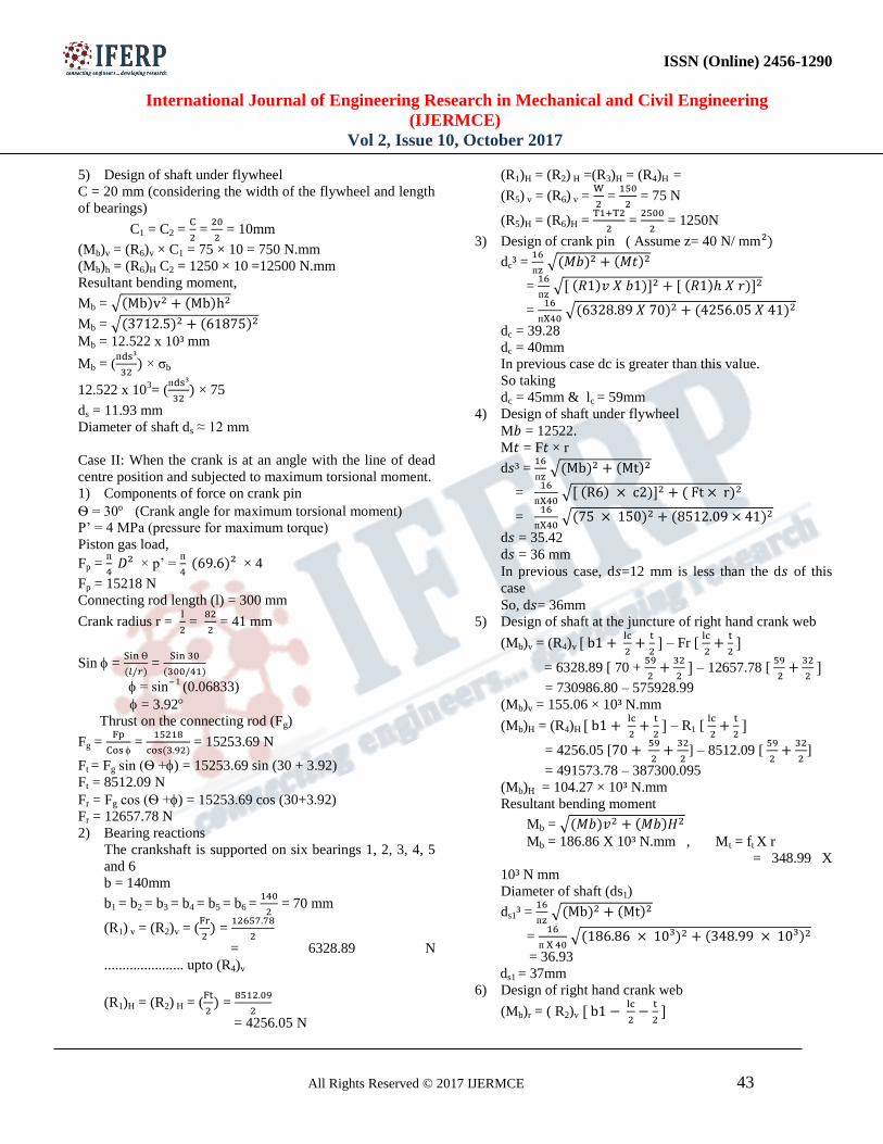
5) Design of shaft under flywheel
C = 20 mm (considering the width of the flywheel and length
of bearings)
C1 = C2 =
=
= 10mm
(Mb)v = (R6)v × C1 = 75 × 10 = 750 N.mm
(Mb)h = (R6)H C2 = 1250 × 10 =12500 N.mm
Resultant bending moment,
Mb = √
Mb = √
Mb = 12.522 x 10³ mm
Mb = (
× σb
12.522 x 103= (
× 75
ds = 11.93 mm
Diameter of shaft ds ≈ 12 mm
Case II: When the crank is at an angle with the line of dead
centre position and subjected to maximum torsional moment.
1) Components of force on crank pin
Ѳ = 30 (Crank angle for maximum torsional moment)
P’ = 4 MPa (pressure for maximum torque)
Piston gas load,
Fp =
× p’ =
× 4
Fp = 15218 N
Connecting rod length (l) = 300 mm
Crank radius r =
=
= 41 mm
Sin =
=
= sin 1 (0.06833)
= 3.92
Thrust on the connecting rod (Fg)
Fg =
=
= 15253.69 N
Ft = Fg sin (Ѳ +) = 15253.69 sin (30 + 3.92)
Ft = 8512.09 N
Fr = Fg cos (Ѳ +) = 15253.69 cos (30+3.92)
Fr = 12657.78 N
2) Bearing reactions
The crankshaft is supported on six bearings 1, 2, 3, 4, 5
and 6
b = 140mm
b1 = b2 = b3 = b4 = b5 = b6 =
= 70 mm
(R1) v = (R2)v = (
=
= 6328.89 N
...................... upto (R4)v
(R1)H = (R2) H = (
=
= 4256.05 N
(R1)H = (R2) H =(R3)H = (R4)H =
(R5) v = (R6) v =
=
= 75 N
(R5)H = (R6)H =
=
= 1250N
3) Design of crank pin ( Assume z= 40 N/ mm
dc³ =
√
=
√
=
√
dc = 39.28
dc = 40mm
In previous case dc is greater than this value.
So taking
dc = 45mm & lc = 59mm
4) Design of shaft under flywheel
M = 12522.
M = F × r
d ³ =
√
=
√
=
√
d = 35.42
d = 36 mm
In previous case, d =12 mm is less than the d of this
case
So, d = 36mm
5) Design of shaft at the juncture of right hand crank web
(Mb)v = (R4)v
– Fr [
= 6328.89 [ 70 +
– 12657.78 [
= 730986.80 – 575928.99
(Mb)v = 155.06 × 10³ N.mm
(Mb)H = (R4)H
– R1 [
= 4256.05 [
] – 8512.09 [
]
= 491573.78 – 387300.095
(Mb)H = 104.27 × 10³ N.mm
Resultant bending moment
Mb = √
Mb = 186.86 X 10³ N.mm , Mt = ft X r
= 348.99 X
10³ N mm
Diameter of shaft (ds1)
ds1³ =
√
=
√
= 36.93
ds1 = 37mm
6) Design of right hand crank web
(Mb)r = ( R2)v
ISSN (Online) 2456-1290
International Journal of Engineering Research in Mechanical and Civil Engineering
(IJERMCE)
Vol 2, Issue 10, October 2017
All Rights Reserved © 2017 IJERMCE 44
= 6328.89 [70 -
]
= 155.06 × 10³ N.mm
(Mb)r = (σb)r [
155.06 × 10³ = (σb)r [
]
(σb)r = 17.47 N/mm²
(Mb)t = Ft [r -
= 8512.09 [41 -
]
= 191.52 × 10³ N.mm
(Mb)t = (σb)t [
191.52 × 10³ = (σb)t [
(σb)t = 13.28 N/mm²
(σc)d = [
= [
= 3.80 N/mm²
(σc) = (σb)r + (σb)t + (σc)d
(σc) = 34.55 N/mm2
Mt = (R2)h [ b2 -
] = 4256.05 [70 -
]
Mt = 172.37 × 10³ N.mm
τ=
=
=
τ = 14.56 N/mm²
(σc)max = 0.5 × [(σc) + √ ]
= 0.5 × [34.55 + √ ] = 39.87 N/mm²
It is less than 75N/mm², so design is safe.
7) Design of left hand crank web
No need to find stresses for left hand crank web. W & t
will be same.
8) Design of crankshaft bearing
Reaction at bearing
R5 =
=
= 10.8365 KN
= 10836.5 N
Total bearing pressure
d5 =1.3ds1 = 48.1 = 49mm
Pb =
=
= 5.98 N/mm²
Bearing pressure for the material = 10 N/mm²
Pb<10 N/mm²
Hence the design is safe. [7]
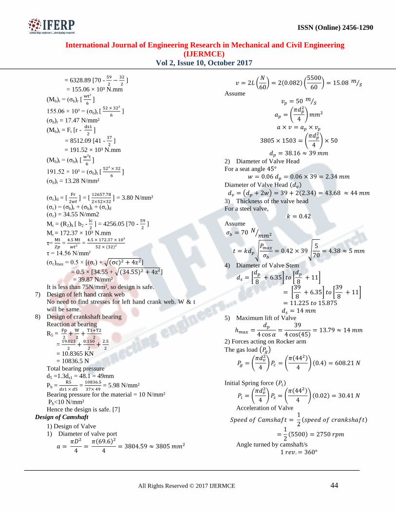
Design of Camshaft
1) Design of Valve
1) Diameter of valve port
(
) (
) ⁄
Assume ⁄
(
)
(
)
2) Diameter of Valve Head
For a seat angle
Diameter of Valve Head
( )
3) Thickness of the valve head
For a steel valve,
Assume
⁄
√
√
4) Diameter of Valve Stem
[
] [
]
[
] [
]
5) Maximum lift of Valve
2) Forces acting on Rocker arm
The gas load ( )
(
) (
)
Initial Spring force
(
) (
)
Acceleration of Valve
Angle turned by camshaft/s

ISSN (Online) 2456-1290
International Journal of Engineering Research in Mechanical and Civil Engineering
(IJERMCE)
Vol 2, Issue 10, October 2017
All Rights Reserved © 2017 IJERMCE 45
(
)
Total crankshaft angle when the valve is open
Total angle of cam
action
Cam angle during constant acceleration
Valve lift during constant acceleration Time taken by valve during constant
acceleration period
3) Design of fulcrum pin
√
(
) (
⁄ )
(
)
(
)
(
) (
)
⁄
4 : Design of forked end
(
) (
⁄ )
(
)
(
)
⁄
(
) (
)
(
)
5) Design of cross section of rocker arm
6)Design of tappet
(
)
Diameter of circular end of rocker arm and
Depth
7: Design of Valve Spring
Assumptions
Spring index =8
Stiffness of spring is 10
Permissible torsional shear stress :
Modulus of rigidity =

ISSN (Online) 2456-1290
International Journal of Engineering Research in Mechanical and Civil Engineering
(IJERMCE)
Vol 2, Issue 10, October 2017
All Rights Reserved © 2017 IJERMCE 46
Total gas between consecutive coils is 15%
of max compression.
Wire diameter
(
)
(
)
Mean coil diameter
Number of active turns
( )( )
Total no. of turns Max compression of spring
Solid length of spring
8) Design of Cam
Diameter of camshaft
D’ 23 mm
The base circle diameter of cam
Roller Diameter
Roller width
Cam width = Roller width
Lift of Valve [7]
VIII. MODELLING AND ANALYSIS OF
CRANKSHAFT
A. Modeling of Crankshaft
A 3-D model of Crankshaft is created in Creo 2.0
software using the dimensions obtained from the design
calculations above. It is as shown in Fig. 11.
Fig. 11 3-D model of Crankshaft in Creo 2.0
B. Static Structural Analysis of Crankshaft (for Case-II)
The 3-D model of crankshaft created using Creo 2.0 software
is imported in ANSYS 17.0 software. It was meshed using
tetrahedron elements. The mesh statistics are as shown in Fig.
12. The meshed model is as shown in Fig. 13
Fig. 12 Mesh statistics for Crankshaft
Fig. 13 Meshed model of crankshaft
Boundary conditions are applied to the meshed crankshaft
which includes force boundary conditions and restriction
boundary conditions. It is as shown in Fig. 14.
Fig. 14 Boundary conditions for Crankshaft
The static structural analysis was run by applying the
materials namely nodular cast iron, cast steel, forged steel
and inconel X-750. Results were obtained for total

ISSN (Online) 2456-1290
International Journal of Engineering Research in Mechanical and Civil Engineering
(IJERMCE)
Vol 2, Issue 10, October 2017
All Rights Reserved © 2017 IJERMCE 47
deformation and equivalent (von-Mises) stress for the
materials as shown in Fig. 15 to Fig. 22 respectively for
Case-II.
Fig. 15 Total deformation for nodular cast iron
Fig. 16 Von-Mises stress for nodular cast iron
Fig. 17 Total deformation for cast steel
Fig. 18 von-Mises stress for cast steel
Fig. 19 Total deformation for forged steel
Fig. 20 von-Mises stress for forged steel
Fig. 21 Total deformation for Inconel-X750
Fig. 22 von-Mises stress for Inconel X-750
IX. MODELLING AND ANALYSIS OF CAMSHAFT
A. Modeling of Camshaft
A 3-D model of camshaft is created in Creo 2.0 software
using the dimensions obtained from the design calculations
above. It is as shown in Fig. 23.

ISSN (Online) 2456-1290
International Journal of Engineering Research in Mechanical and Civil Engineering
(IJERMCE)
Vol 2, Issue 10, October 2017
All Rights Reserved © 2017 IJERMCE 48
Fig. 23 3-D model of camshaft
B. Static Structural Analysis of Camshaft
The 3-D model of crankshaft created using Creo 2.0 software
is imported in ANSYS 17.0 software. It is meshed using
tetrahedron elements. The mesh statistics are as shown in Fig.
24. The meshed model is as shown in Fig. 25.
Fig. 24 Mesh statistics for camshaft
Fig. 25 Meshed model of camshaft
Boundary conditions are applied to the meshed crankshaft
which includes force boundary conditions and restriction
boundary conditions. It is as shown in Fig. 26.
Fig. 26 Boundary conditions for camshaft
The static structural analysis was run by applying the
materials namely white cast iron and nodular cast iron.
Results were obtained for total deformation and equivalent
(von-Mises) stress for the materials as shown Fig. 27 to Fig.
30 respectively
Fig. 27 Total deformation for white cast iron
Fig. 28 von-Mises stress for white cast iron
Fig. 29 Total deformation in nodular cast iron
Fig. 30 von-Mises stress in nodular cast iron
ISSN (Online) 2456-1290
International Journal of Engineering Research in Mechanical and Civil Engineering
(IJERMCE)
Vol 2, Issue 10, October 2017
All Rights Reserved © 2017 IJERMCE 49
X. EXPERIMENTAL ANALYSIS
After carrying out FEM based stress analysis using ANSYS
software, a basic level experimentation is also carried out on
the crankshaft and camshaft on a universal testing machine
for static loading conditions. The crankshaft and camshaft
used for this experimentation was obtained from a TATA
Indica Vista Quadrajet (Diesel version). The material
specifications of these are as shown in Table 2. According to
the chemical composition, the crankshaft material was
equivalent to EN8 (forged steel), while that of camshaft was
equivalent to nodular cast iron (SG iron).
Table 2 Material properties of TATA Indica Vista
Quadrajet car crankshaft and camshaft obtained from
testing
The crankshaft was tested using a big universal testing
machine having a capacity of 10 tons. It was mounted on the
engine block of TATA Indica Vista Quadrajet car on the
machine bed. In case-I (crank is at TDC position) of loading,
a maximum static load of 19023 N was applied at the centre
of one crankpin, whereas in case-II (crank is at 30º from
TDC), a load of 15218 N was applied at the centre of one
crankpin. This was done one after the other. The arrangement
is as shown in Fig. 31 and Fig. 32. The values of deformation
and stress obtained from the testing are as shown in Table 3.
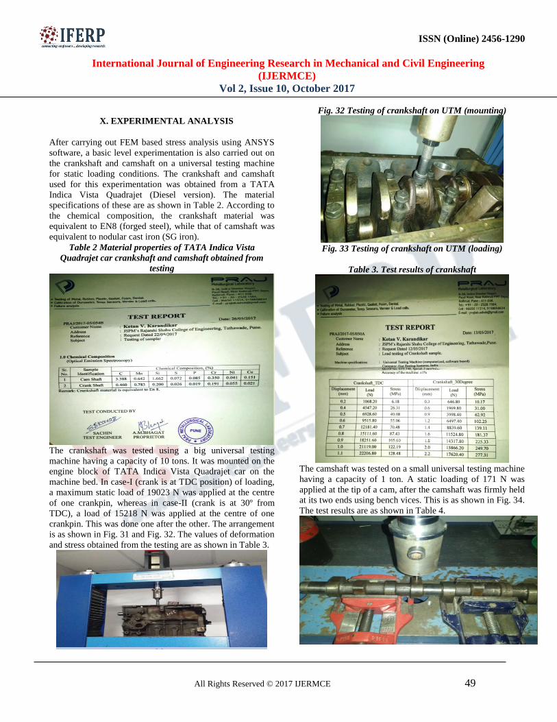
Fig. 32 Testing of crankshaft on UTM (mounting)
Fig. 33 Testing of crankshaft on UTM (loading)
Table 3. Test results of crankshaft
The camshaft was tested on a small universal testing machine
having a capacity of 1 ton. A static loading of 171 N was
applied at the tip of a cam, after the camshaft was firmly held
at its two ends using bench vices. This is as shown in Fig. 34.
The test results are as shown in Table 4.

ISSN (Online) 2456-1290
International Journal of Engineering Research in Mechanical and Civil Engineering
(IJERMCE)
Vol 2, Issue 10, October 2017
All Rights Reserved © 2017 IJERMCE 50
Fig. 34 Testing of camshaft on UTM (loading)
Table 4 Test results of camshaft
XI. RESULTS
The comparison of analytical (ANSYS software) results for
different materials of crankshaft is as shown in Table 5
Table 5. Comparison of analytical results for crankshaft
(for Case-II)
Sr.
No.
Parameter Nodular
Cast
Iron
(ASTM
100-70-
03)
Cast
Steel
(GS 70)
Forged
Steel
(AISI
1045)
Inconel
X-750
1. Total
deformatio
n (mm)
0.023424 0.02009
8
0.019384
0.018734
2. Von-Mises
stress
(N/mm2)
264.26 261.95 261.95 262.94
The comparison of analytical (ANSYS software) results for
different materials of camshaft is as shown in Table 6.
Table 6. Comparison of analytical results for camshaft (for
Case-II)
Sr.
No.
Parameter White Cast
Iron
Nodular Cast
Iron (SG Iron)
1. Total deformation
(mm)
0.00012457
0.00011559
2. Von-Mises stress
(N/mm2)
0.61186
0.6177
XII. VALIDATION OF RESULTS
The analytical results were compared with the experimental
results for validation purpose as shown in Table 7.
Table 7. Validation of Results
Some variation or discrepancy was found in the analytical
and experimental results because of variation in material
properties, unavailability of a highly costly and dedicated test
rig and related fixtures. These variations were reasonably
small.
XIII. CONCLUSIONS
The crankshaft and camshaft are designed to calculate their
dimensions using theoretical design equations. The respective
stresses calculated are less than the yield strength of the
material. This ensures safety of the design. These dimensions
are used to design the 3-D models in Creo 2.0
software.Concluding from the analytical results of Case-II for
the crankshaft, none of the materials break. Inconel X-750
shows the minimum deformation and a high factor of safety
at 3.23 based on its yield strength. Also, it is lighter in weight
than other materials. This undoubtedly makes it the best
alternative for existing materials from which the crankshaft is
manufactured. It though is about three times costlier than
steel grades, making it expensive and requires a special
manufacturing process. Hence, it can be ideal for high
performance cars like racing cars, supercars and high end
luxury cars. Forged steel (AISI 1045) shows minimum value
of stress and total deformation as compared to nodular cast
iron and cast steel. Thus, it becomes the best suited material
for manufacturing crankshafts of passenger cars and SUV’s,

ISSN (Online) 2456-1290
International Journal of Engineering Research in Mechanical and Civil Engineering
(IJERMCE)
Vol 2, Issue 10, October 2017
All Rights Reserved © 2017 IJERMCE 51
where a combination of strength and refinement is required.
The analytical results of camshaft show that nodular cast iron
shows less deformation than white cast iron, both materials
showing almost same stress. Thus, it is a better material for
manufacturing camshafts as compared to white cast iron
since it can inhibit the development of cracks.
It was observed from the stress analysis using
ANSYS software, maximum deformation or displacement in
crankshaft happens at the top central portion of the crankpin.
The maximum stresses befall in the regions where there is
quite a sudden change in the geometry of the crankshaft. This
area is the junction where the crank web connects the shaft.
This is a natural because the stress lines suddenly change
themselves. This leads to the accumulation of high stresses
over there, making the material weak. These fillets should be
designed such that the crankshaft is least affected by these
high stresses. Also, high surface finish should be maintained
to minimize these stresses. This may be the reason that the
manufacturers nowadays prefer forged materials over cast
materials. Since the crankshaft is a rotating element and is
imperilled by cyclic loading, there are chances of fatigue
cracks being developed in these locations over time. This
finally leads to fatigue failure.
REFERENCES
[1] Akkamahdevi G. Chanagond and L.B. Raut, “Finite
Element Analysis of Roller Cam by Optimization of Surface
Contact Area”, International Journal of Advanced
Engineering Research and Studies (IJAERS), E-ISSN 2249-
8974, Vol. IV, Issue II, Jan-March 2015, pp. 05-06.
[2] Dr. Dmitri Kopeliovich, “Camshaft Bearings”, Engine
Professional, Jan-March 2015, pp. 82-86.
[3] Farzin H. Montazersadgh and Ali Fatemi,
“DynamicLoad and Stress Analysis of a Crankshaft,” SAE
International, 2007-01-0258.
[4] Amit Solanki and Jaydeepsinh Dodiya, “Design and
Stress Analysis of Crankshaft for Single Cylinder 4-Stroke
Diesel Engine”, International Journal for Research in Applied
Science and Engineering Technology (IJRASET), ISSN
2321-9653, Vol. 2, Issue V, May 2014, pp. 320-324.
[5] Vivekanandan.P and Kumar. M, “Modelling, Design and
Finite Element Analysis of Cam Shaft”, International Journal
of Current Engineering and Technology (IJCET), ISSN
2277-4106, Vol. 3, Issue 1, March 2013, pp. 220-223.
[6] D Jagan and V Ganesh, “Design and Analysis of a
Camshaft using Al-SiC Composite with a Study of Latest
Trends in Diesel Technologies”, International Journal of
Innovations in Engineering and Technology (IJIET), ISSN:
2319-1058, Vol. 7, Issue 1, June 2016, pp. 566-574.
[7] Machine Design by R.S. Khurmi and J.K. Gupta, Eurasia
Publishing House (P) Ltd., New Delhi
[8] Prajakta P. Pawar, Dr. Santosh D.Dalvi, Santosh Rane
and Dr. Chandra Babu Divakaran, “Evaluation of Crankshaft
Manufacturing Methods -An Overview of Material Removal
and Additive Processes”, International Research Journal of
Engineering and Technology (IRJET), Vol. 2, Issue 4, July
2015.
[9] Sujata Satish Shenkar and Nagraj Biradar, “Design and
Static Structural Analysis of Crank Shaft”, International
Journal of Scientific Engineering and Technology Research
(IJSETR), ISSN 2319-8885, Vol. 4, Issue 7, March 2015, pp.
1393-1398.
[10]P. Preetham and S. Srinivasa Prasad, “Design and
Analysis of Six Cylinder Four Stroke Engine Crank Shaft”,
Journal of Technological Advances and Scientific Research
(JTASR), eISSN- 2454-1788, ISSN- 2395-5600, Vol. 2,
Issue 1, January-March 2016.
[11] Jian Meng, Yongqi Liu and Ruixiang Liu,“Finite
Element Analysis of 4-Cylinder Diesel Crankshaft, ”
International Journal of Image,Graphics and Signal
Processing, 5, 22-29, August 2007.
[12] B. Mounika and Madhuri .R .P, “Structural Static
Analysis of Crankshaft”, International Journal of Science and
Research (IJSR), ISSN (Online)-2319-7064, Vol. 6, Issue 5,
May 2017, pp. 987-987.