Embed Size (px)
Citation preview
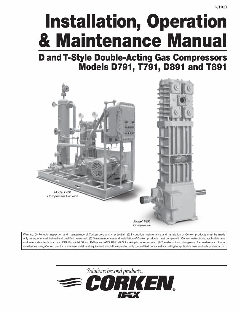
Model T891Compressor
Model D891 Compressor Package
IJ110D
Installation, Operation & Maintenance ManualD and T-Style Double-Acting Gas Compressors
Models D791, T791, D891 and T891
Warning: (1) Periodic inspection and maintenance of Corken products is essential. (2) Inspection, maintenance and installation of Corken products must be made only by experienced, trained and qualified personnel. (3) Maintenance, use and installation of Corken products must comply with Corken instructions, applicable laws and safety standards (such as NFPA Pamphlet 58 for LP-Gas and ANSI K61.1-1972 for Anhydrous Ammonia). (4) Transfer of toxic, dangerous, flammable or explosive substances using Corken products is at user’s risk and equipment should be operated only by qualified personnel according to applicable laws and safety standards.
WarningInstall, use and maintain this equipment according to Corken, Inc. instructions and all applicable federal, state, local laws and codes, and NFPA Pamphlet 58 for LP-Gas or ANSI K61.1-1989 for Anhydrous Ammonia. Periodic inspection and maintenance is essential.
Corken One Year Limited WarrantyCorken, Inc. warrants that its products will be free from defects in material and workmanship for a period of 12 months following date of purchase from Corken. Corken products which fail within the warranty period due to defects in material or workmanship will be repaired or replaced at Corken’s option, when returned freight prepaid to: Corken, Inc., 3805 N.W. 36th Street, Oklahoma City, Oklahoma 73112.
Parts subject to wear or abuse, such as mechanical seals, blades, piston rings, valves, and packing, and other parts showing signs of abuse are not covered by this limited warranty. Also, equipment, parts and accessories not manufactured by Corken but furnished with Corken products are not covered by this limited warranty and purchaser must look to the original manufacturer’s warranty, if any. This limited warranty is void if the Corken product has been altered or repaired without the consent of Corken.
ALL impLied WArrAnties, inCLuding AnY impLied WArrAntY Of merChAntAbiLitY Or fitness fOr A pArtiCuLAr purpOse, Are expressLY negAted tO the extent permitted bY LAW And shALL in nO event extend beYOnd the expressed WArrAntY periOd.
Corken disclaims any liability for consequential damages due to breach of any written or implied warranty on Corken products. Transfer of toxic, dangerous, flammable or explosive substances using Corken products is at the user’s risk. Such substances should be handled by experienced, trained personnel in compliance with governmental and industrial safety standards.
Contacting the factoryFor your convenience, the model number and serial number are given on the compressor nameplate. Space is provided below for you to keep a written record of this information.
Always include the model number and serial number when ordering parts.
Model No.
Serial No.
Date Purchased
Date Installed
Purchased From
Installed By
2
table of ContentsfeAtures And benefits . . . . . . . . . . . . . . . . . . . . . . . . . . . . . . . . . . . . . . . . . . . . . . . . . . . . . . . . . . . . . . . . . . . . . 4
ChApter 1—instALLing YOur COrken COmpressOr . . . . . . . . . . . . . . . . . . . . . . . . . . . . . . . . . . . . . . . . . . 5
1.1 Location . . . . . . . . . . . . . . . . . . . . . . . . . . . . . . . . . . . . . . . . . . . . . . . . . . . . . . . . . . . . . . . . . . . . . . . . . . . . . . . . . 5
1.2 Foundation . . . . . . . . . . . . . . . . . . . . . . . . . . . . . . . . . . . . . . . . . . . . . . . . . . . . . . . . . . . . . . . . . . . . . . . . . . . . . . . 5
1.3 Piping . . . . . . . . . . . . . . . . . . . . . . . . . . . . . . . . . . . . . . . . . . . . . . . . . . . . . . . . . . . . . . . . . . . . . . . . . . . . . . . . . . . 5
1.4 Liquid Trap . . . . . . . . . . . . . . . . . . . . . . . . . . . . . . . . . . . . . . . . . . . . . . . . . . . . . . . . . . . . . . . . . . . . . . . . . . . . . . . 6
1.5 Driver Installation/Flywheels . . . . . . . . . . . . . . . . . . . . . . . . . . . . . . . . . . . . . . . . . . . . . . . . . . . . . . . . . . . . . . . . . 6
1.6 Crankcase Lubrication . . . . . . . . . . . . . . . . . . . . . . . . . . . . . . . . . . . . . . . . . . . . . . . . . . . . . . . . . . . . . . . . . . . . . . 6
1.7 Purging, Padding, Venting and Draining of Distance Pieces . . . . . . . . . . . . . . . . . . . . . . . . . . . . . . . . . . . . . . . . . 7
1.8 Relief Valves . . . . . . . . . . . . . . . . . . . . . . . . . . . . . . . . . . . . . . . . . . . . . . . . . . . . . . . . . . . . . . . . . . . . . . . . . . . . . . 8
1.9 Shutdown/Alarm Devices . . . . . . . . . . . . . . . . . . . . . . . . . . . . . . . . . . . . . . . . . . . . . . . . . . . . . . . . . . . . . . . . . . . . 8
ChApter 2—stArting up YOur COrken COmpressOr . . . . . . . . . . . . . . . . . . . . . . . . . . . . . . . . . . . . . . . . 9
2.1 Inspection After Extended Storage . . . . . . . . . . . . . . . . . . . . . . . . . . . . . . . . . . . . . . . . . . . . . . . . . . . . . . . . . . . . 9
2.2 Flywheel and V-belt Alignment . . . . . . . . . . . . . . . . . . . . . . . . . . . . . . . . . . . . . . . . . . . . . . . . . . . . . . . . . . . . . . . 9
2.3 Crankcase Oil Pressure Adjustment . . . . . . . . . . . . . . . . . . . . . . . . . . . . . . . . . . . . . . . . . . . . . . . . . . . . . . . . . . . 9
2.4 Startup Check List . . . . . . . . . . . . . . . . . . . . . . . . . . . . . . . . . . . . . . . . . . . . . . . . . . . . . . . . . . . . . . . . . . . . . . . . 10
ChApter 3—rOutine mAintenAnCe ChArt . . . . . . . . . . . . . . . . . . . . . . . . . . . . . . . . . . . . . . . . . . . . . . . . . . 11
ChApter 4—rOutine serviCe And repAir prOCedures . . . . . . . . . . . . . . . . . . . . . . . . . . . . . . . . . . . . . . 12
4.1 Valves . . . . . . . . . . . . . . . . . . . . . . . . . . . . . . . . . . . . . . . . . . . . . . . . . . . . . . . . . . . . . . . . . . . . . . . . . . . . . . . . . . 12
4.2 Heads . . . . . . . . . . . . . . . . . . . . . . . . . . . . . . . . . . . . . . . . . . . . . . . . . . . . . . . . . . . . . . . . . . . . . . . . . . . . . . . . . . 13
4.3 Piston Rings and Piston Ring Expanders . . . . . . . . . . . . . . . . . . . . . . . . . . . . . . . . . . . . . . . . . . . . . . . . . . . . . . 13
4.4 Piston Replacement . . . . . . . . . . . . . . . . . . . . . . . . . . . . . . . . . . . . . . . . . . . . . . . . . . . . . . . . . . . . . . . . . . . . . . . 13
4.5 Piston Rod Packing Adjustment . . . . . . . . . . . . . . . . . . . . . . . . . . . . . . . . . . . . . . . . . . . . . . . . . . . . . . . . . . . . . 14
4.6 Cylinder and Packing Replacement . . . . . . . . . . . . . . . . . . . . . . . . . . . . . . . . . . . . . . . . . . . . . . . . . . . . . . . . . . 14
4.7 Bearing Replacement for Crankcase and Connecting Rod . . . . . . . . . . . . . . . . . . . . . . . . . . . . . . . . . . . . . . . . 17
4.8 Oil Pump Inspection. . . . . . . . . . . . . . . . . . . . . . . . . . . . . . . . . . . . . . . . . . . . . . . . . . . . . . . . . . . . . . . . . . . . . . . 18
ChApter 5—extended stOrAge prOCedures . . . . . . . . . . . . . . . . . . . . . . . . . . . . . . . . . . . . . . . . . . . . . . . 19
AppendiCes
A. Vertical Double-Acting Model Number Identification Code . . . . . . . . . . . . . . . . . . . . . . . . . . . . . . . . . . . . . . . . . 20
B. Vertical Double-Acting Specifications. . . . . . . . . . . . . . . . . . . . . . . . . . . . . . . . . . . . . . . . . . . . . . . . . . . . . . . . . . 22
C. Outline Dimensions . . . . . . . . . . . . . . . . . . . . . . . . . . . . . . . . . . . . . . . . . . . . . . . . . . . . . . . . . . . . . . . . . . . . . . . . 24
D. Troubleshooting . . . . . . . . . . . . . . . . . . . . . . . . . . . . . . . . . . . . . . . . . . . . . . . . . . . . . . . . . . . . . . . . . . . . . . . . . . . 32
E. Assembly Details . . . . . . . . . . . . . . . . . . . . . . . . . . . . . . . . . . . . . . . . . . . . . . . . . . . . . . . . . . . . . . . . . . . . . . . . . . 34
3
features and benefits
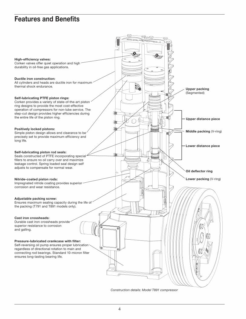
high-efficiency valves:Corken valves offer quiet operation and high durability in oil-free gas applications.
ductile iron construction:All cylinders and heads are ductile iron for maximum thermal shock endurance.
self-lubricating ptfe piston rings:Corken provides a variety of state-of-the-art piston ring designs to provide the most cost-effective operation of compressors for non-lube service. The step-cut design provides higher efficiencies during the entire life of the piston ring.
positively locked pistons:Simple piston design allows end clearance to be precisely set to provide maximum efficiency and long life.
self-lubricating piston rod seals:Seals constructed of PTFE incorporating special fillers to ensure no oil carry over and maximize leakage control. Spring loaded seal design self adjusts to compensate for normal wear.
nitride-coated piston rods:Impregnated nitride coating provides superior corrosion and wear resistance.
Adjustable packing screw: Ensures maximum sealing capacity during the life of the packing (T791 and T891 models only).
Cast iron crossheads:Durable cast iron crossheads provide superior resistance to corrosion and galling.
pressure-lubricated crankcase with filter:Self-reversing oil pump ensures proper lubrication regardless of directional rotation to main and connecting rod bearings. Standard 10-micron filter ensures long-lasting bearing life.
Lower packing (V-ring)
middle packing (V-ring)
upper packing(Segmented)
upper distance piece
Lower distance piece
Construction details: Model T891 compressor
Oil deflector ring
4
1.1 LocationnOte: Compressor must be installed in a well ventilated area.
Corken compressors are designed and manufactured for outdoor duty. For applications where the compressor will be subjected to extreme conditions for extended periods such as corrosive environments, arctic conditions, etc., consult Corken. Check local safety regulations and building codes to assure installation will meet local safety standards.
Corken compressors handling toxic or flammable gases such as Lpg/nh3 should be located outdoors in a well ventilated area. A minimum of 18 inches (45 cm) clearance between the compressor and the nearest wall is advised to make it accessible from all sides and to provide unrestricted air flow for adequate cooling.
noise:Corken vertical compressors should not exceed an 85 DBA noise level when properly installed.
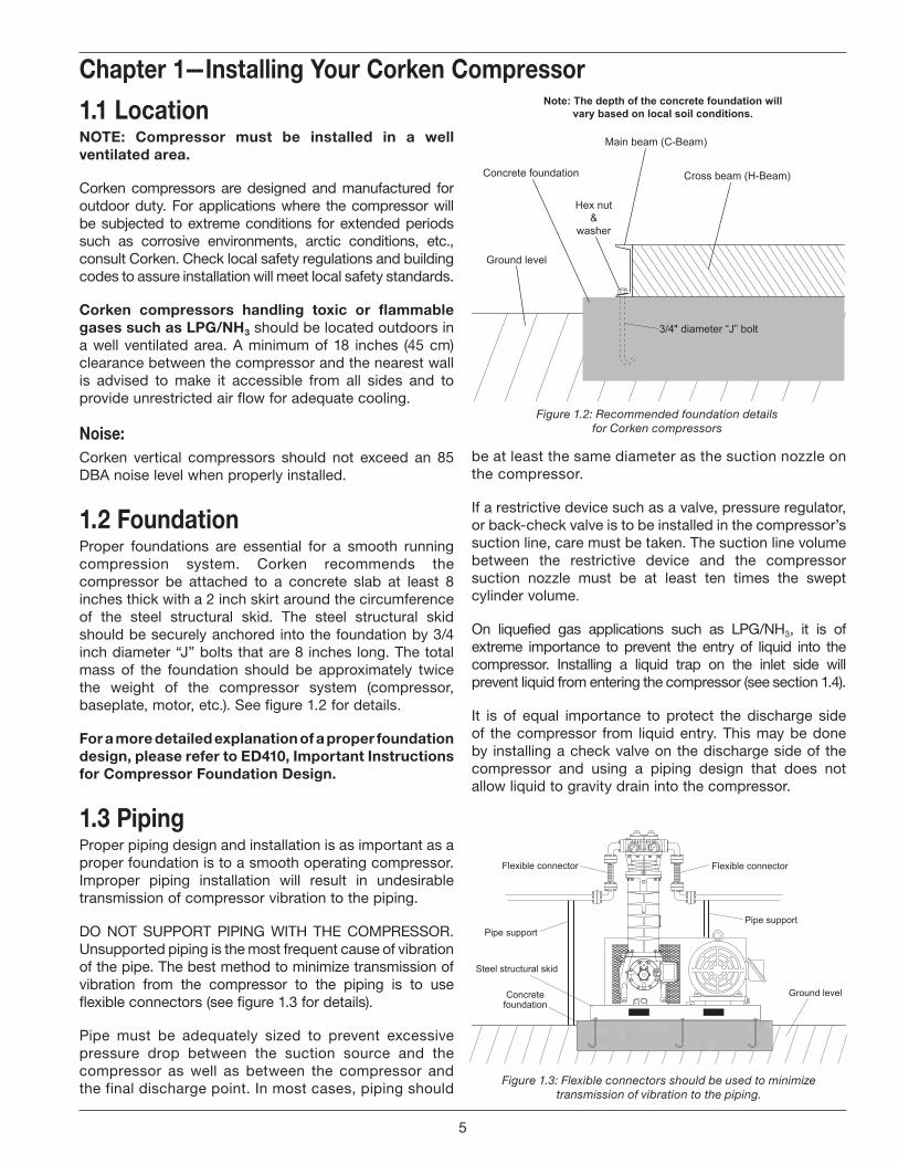
1.2 foundationProper foundations are essential for a smooth running compression system. Corken recommends the compressor be attached to a concrete slab at least 8 inches thick with a 2 inch skirt around the circumference of the steel structural skid. The steel structural skid should be securely anchored into the foundation by 3/4 inch diameter “J” bolts that are 8 inches long. The total mass of the foundation should be approximately twice the weight of the compressor system (compressor, baseplate, motor, etc.). See figure 1.2 for details.
for a more detailed explanation of a proper foundation design, please refer to ed410, important instructions for Compressor foundation design.
1.3 pipingProper piping design and installation is as important as a proper foundation is to a smooth operating compressor. Improper piping installation will result in undesirable transmission of compressor vibration to the piping.
DO NOT SUPPORT PIPING WITH THE COMPRESSOR. Unsupported piping is the most frequent cause of vibration of the pipe. The best method to minimize transmission of vibration from the compressor to the piping is to use flexible connectors (see figure 1.3 for details).
Pipe must be adequately sized to prevent excessive pressure drop between the suction source and the compressor as well as between the compressor and the final discharge point. In most cases, piping should
be at least the same diameter as the suction nozzle on the compressor.
If a restrictive device such as a valve, pressure regulator, or back-check valve is to be installed in the compressor’s suction line, care must be taken. The suction line volume between the restrictive device and the compressor suction nozzle must be at least ten times the swept cylinder volume.
On liquefied gas applications such as LPG/NH3, it is of extreme importance to prevent the entry of liquid into the compressor. Installing a liquid trap on the inlet side will prevent liquid from entering the compressor (see section 1.4).
It is of equal importance to protect the discharge side of the compressor from liquid entry. This may be done by installing a check valve on the discharge side of the compressor and using a piping design that does not allow liquid to gravity drain into the compressor.
Chapter 1—installing Your Corken Compressor
Figure 1.2: Recommended foundation details for Corken compressors
Ground levelConcretefoundation
Steel structural skid
Pipe supportPipe support
Flexible connector Flexible connector
Figure 1.3: Flexible connectors should be used to minimize transmission of vibration to the piping.
Main beam (C-Beam)
Cross beam (H-Beam)
3/4″ diameter “J” bolt
Hex nut&
washer
Concrete foundation
Note: The depth of the concrete foundation willvary based on local soil conditions.
5
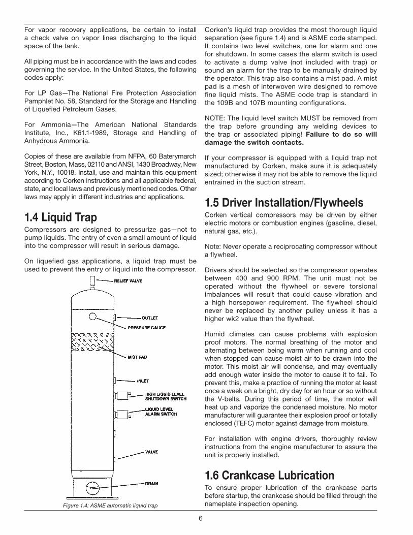
Figure 1.4: ASME automatic liquid trap
Corken’s liquid trap provides the most thorough liquid separation (see figure 1.4) and is ASME code stamped. It contains two level switches, one for alarm and one for shutdown. In some cases the alarm switch is used to activate a dump valve (not included with trap) or sound an alarm for the trap to be manually drained by the operator. This trap also contains a mist pad. A mist pad is a mesh of interwoven wire designed to remove fine liquid mists. The ASME code trap is standard in the 109B and 107B mounting configurations.
NOTE: The liquid level switch MUST be removed from the trap before grounding any welding devices to the trap or associated piping! failure to do so will damage the switch contacts.
If your compressor is equipped with a liquid trap not manufactured by Corken, make sure it is adequately sized; otherwise it may not be able to remove the liquid entrained in the suction stream.
1.5 driver installation/flywheelsCorken vertical compressors may be driven by either electric motors or combustion engines (gasoline, diesel, natural gas, etc.).
Note: Never operate a reciprocating compressor without a flywheel.
Drivers should be selected so the compressor operates between 400 and 900 RPM. The unit must not be operated without the flywheel or severe torsional imbalances will result that could cause vibration and a high horsepower requirement. The flywheel should never be replaced by another pulley unless it has a higher wk2 value than the flywheel.
Humid climates can cause problems with explosion proof motors. The normal breathing of the motor and alternating between being warm when running and cool when stopped can cause moist air to be drawn into the motor. This moist air will condense, and may eventually add enough water inside the motor to cause it to fail. To prevent this, make a practice of running the motor at least once a week on a bright, dry day for an hour or so without the V-belts. During this period of time, the motor will heat up and vaporize the condensed moisture. No motor manufacturer will guarantee their explosion proof or totally enclosed (TEFC) motor against damage from moisture.
For installation with engine drivers, thoroughly review instructions from the engine manufacturer to assure the unit is properly installed.
1.6 Crankcase LubricationTo ensure proper lubrication of the crankcase parts before startup, the crankcase should be filled through the nameplate inspection opening.
For vapor recovery applications, be certain to install a check valve on vapor lines discharging to the liquid space of the tank.
All piping must be in accordance with the laws and codes governing the service. In the United States, the following codes apply:
For LP Gas—The National Fire Protection Association Pamphlet No. 58, Standard for the Storage and Handling of Liquefied Petroleum Gases.
For Ammonia—The American National Standards Institute, Inc., K61.1-1989, Storage and Handling of Anhydrous Ammonia.
Copies of these are available from NFPA, 60 Baterymarch Street, Boston, Mass, 02110 and ANSI, 1430 Broadway, New York, N.Y., 10018. Install, use and maintain this equipment according to Corken instructions and all applicable federal, state, and local laws and previously mentioned codes. Other laws may apply in different industries and applications.
1.4 Liquid trapCompressors are designed to pressurize gas—not to pump liquids. The entry of even a small amount of liquid into the compressor will result in serious damage.
On liquefied gas applications, a liquid trap must be used to prevent the entry of liquid into the compressor.
6
CompressorModel
ApproximateQuarts
CapacityLiters
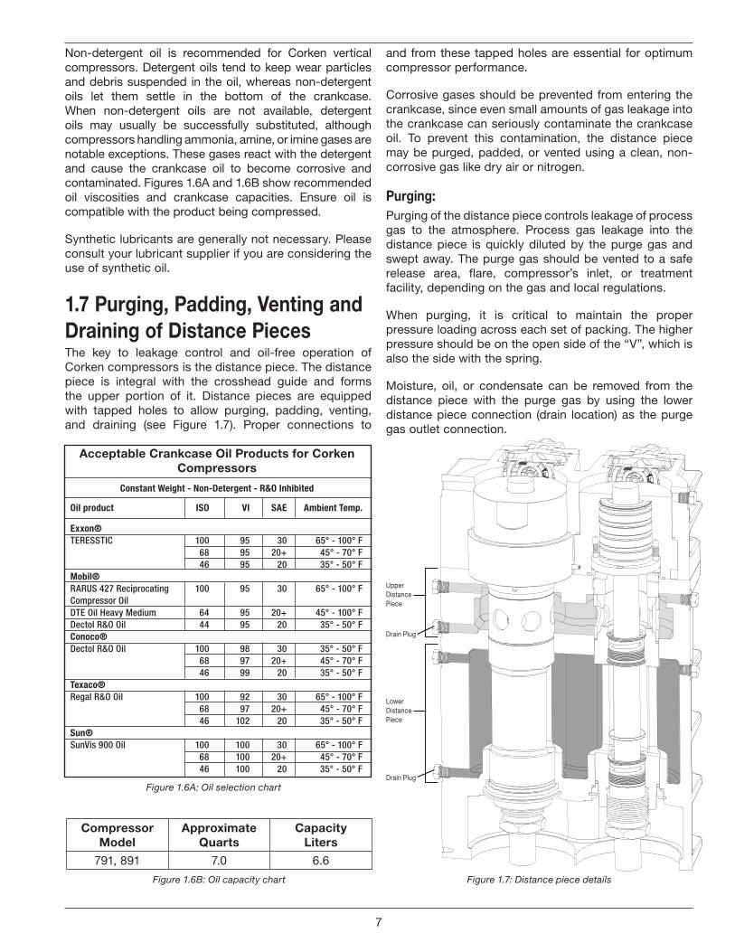
791, 891 7.0 6.6
Figure 1.6B: Oil capacity chart
Acceptable Crankcase Oil Products for Corken Compressors
Constant Weight - Non-Detergent - R&O Inhibited
Oil product ISO VI SAE Ambient Temp.
Exxon®TeressTic 100 95 30 65° - 100° F 68 95 20+ 45° - 70° F 46 95 20 35° - 50° FMobil®rArUs 427 reciprocating 100 95 30 65° - 100° Fcompressor OilDTe Oil Heavy Medium 64 95 20+ 45° - 100° FDectol r&O Oil 44 95 20 35° - 50° FConoco®Dectol r&O Oil 100 98 30 35° - 50° F 68 97 20+ 45° - 70° F 46 99 20 35° - 50° FTexaco®regal r&O Oil 100 92 30 65° - 100° F 68 97 20+ 45° - 70° F 46 102 20 35° - 50° FSun®sunVis 900 Oil 100 100 30 65° - 100° F 68 100 20+ 45° - 70° F 46 100 20 35° - 50° F
Figure 1.6A: Oil selection chart
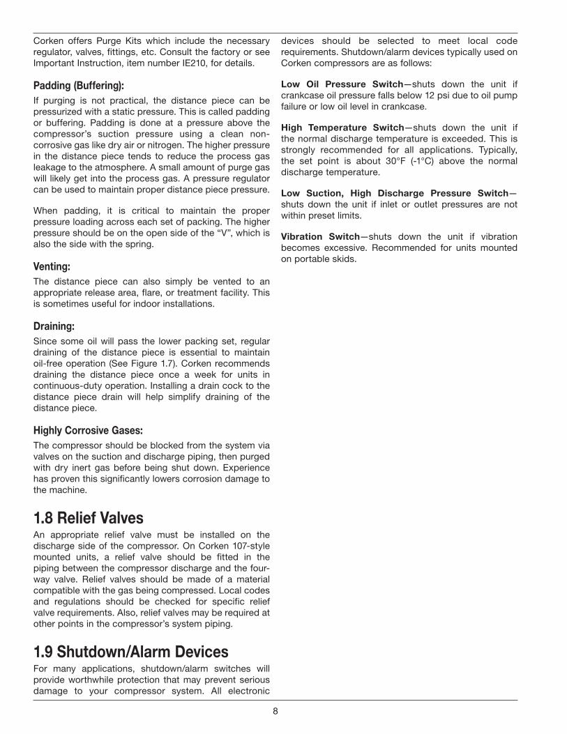
Figure 1.7: Distance piece details
Upper Distance Piece
Drain Plug
Lower Distance Piece
Drain Plug
and from these tapped holes are essential for optimum compressor performance.
Corrosive gases should be prevented from entering the crankcase, since even small amounts of gas leakage into the crankcase can seriously contaminate the crankcase oil. To prevent this contamination, the distance piece may be purged, padded, or vented using a clean, non-corrosive gas like dry air or nitrogen.
Purging:Purging of the distance piece controls leakage of process gas to the atmosphere. Process gas leakage into the distance piece is quickly diluted by the purge gas and swept away. The purge gas should be vented to a safe release area, flare, compressor’s inlet, or treatment facility, depending on the gas and local regulations.
When purging, it is critical to maintain the proper pressure loading across each set of packing. The higher pressure should be on the open side of the “V”, which is also the side with the spring.
Moisture, oil, or condensate can be removed from the distance piece with the purge gas by using the lower distance piece connection (drain location) as the purge gas outlet connection.
Non-detergent oil is recommended for Corken vertical compressors. Detergent oils tend to keep wear particles and debris suspended in the oil, whereas non-detergent oils let them settle in the bottom of the crankcase. When non-detergent oils are not available, detergent oils may usually be successfully substituted, although compressors handling ammonia, amine, or imine gases are notable exceptions. These gases react with the detergent and cause the crankcase oil to become corrosive and contaminated. Figures 1.6A and 1.6B show recommended oil viscosities and crankcase capacities. Ensure oil is compatible with the product being compressed.
Synthetic lubricants are generally not necessary. Please consult your lubricant supplier if you are considering the use of synthetic oil.
1.7 Purging, Padding, Venting and Draining of Distance PiecesThe key to leakage control and oil-free operation of Corken compressors is the distance piece. The distance piece is integral with the crosshead guide and forms the upper portion of it. Distance pieces are equipped with tapped holes to allow purging, padding, venting, and draining (see Figure 1.7). Proper connections to
7
Corken offers Purge Kits which include the necessary regulator, valves, fittings, etc. Consult the factory or see Important Instruction, item number IE210, for details.
padding (buffering):If purging is not practical, the distance piece can be pressurized with a static pressure. This is called padding or buffering. Padding is done at a pressure above the compressor’s suction pressure using a clean non-corrosive gas like dry air or nitrogen. The higher pressure in the distance piece tends to reduce the process gas leakage to the atmosphere. A small amount of purge gas will likely get into the process gas. A pressure regulator can be used to maintain proper distance piece pressure.
When padding, it is critical to maintain the proper pressure loading across each set of packing. The higher pressure should be on the open side of the “V”, which is also the side with the spring.
venting:The distance piece can also simply be vented to an appropriate release area, flare, or treatment facility. This is sometimes useful for indoor installations.
draining:Since some oil will pass the lower packing set, regular draining of the distance piece is essential to maintain oil-free operation (See Figure 1.7). Corken recommends draining the distance piece once a week for units in continuous-duty operation. Installing a drain cock to the distance piece drain will help simplify draining of the distance piece.
highly Corrosive gases: The compressor should be blocked from the system via valves on the suction and discharge piping, then purged with dry inert gas before being shut down. Experience has proven this significantly lowers corrosion damage to the machine.
1.8 relief valvesAn appropriate relief valve must be installed on the discharge side of the compressor. On Corken 107-style mounted units, a relief valve should be fitted in the piping between the compressor discharge and the four-way valve. Relief valves should be made of a material compatible with the gas being compressed. Local codes and regulations should be checked for specific relief valve requirements. Also, relief valves may be required at other points in the compressor’s system piping.
1.9 shutdown/Alarm devicesFor many applications, shutdown/alarm switches will provide worthwhile protection that may prevent serious damage to your compressor system. All electronic
devices should be selected to meet local code requirements. Shutdown/alarm devices typically used on Corken compressors are as follows:
Low Oil pressure switch—shuts down the unit if crankcase oil pressure falls below 12 psi due to oil pump failure or low oil level in crankcase.
high temperature switch—shuts down the unit if the normal discharge temperature is exceeded. This is strongly recommended for all applications. Typically, the set point is about 30°F (-1°C) above the normal discharge temperature.
Low suction, high discharge pressure switch—shuts down the unit if inlet or outlet pressures are not within preset limits.
vibration switch —shuts down the unit if vibration becomes excessive. Recommended for units mounted on portable skids.
8
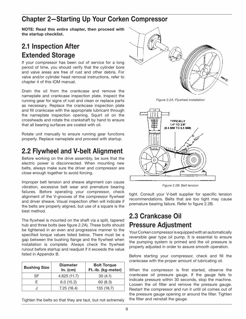
Figure 2.2A: Flywheel installation
Figure 2.2B: Belt tension
tight. Consult your V-belt supplier for specific tension recommendations. Belts that are too tight may cause premature bearing failure. Refer to figure 2.2B.
2.3 Crankcase Oil pressure AdjustmentYour Corken compressor is equipped with an automatically reversible gear type oil pump. It is essential to ensure the pumping system is primed and the oil pressure is properly adjusted in order to assure smooth operation.
Before starting your compressor, check and fill the crankcase with the proper amount of lubricating oil.
When the compressor is first started, observe the crankcase oil pressure gauge. If the gauge fails to indicate pressure within 30 seconds, stop the machine. Loosen the oil filter and remove the pressure gauge. Restart the compressor and run it until oil comes out of the pressure gauge opening or around the filter. Tighten the filter and reinstall the gauge.
nOte: read this entire chapter, then proceed with the startup checklist.
2.1 inspection After extended storageIf your compressor has been out of service for a long period of time, you should verify that the cylinder bore and valve areas are free of rust and other debris. For valve and/or cylinder head removal instructions, refer to chapter 4 of this IOM manual.
Drain the oil from the crankcase and remove the nameplate and crankcase inspection plate. Inspect the running gear for signs of rust and clean or replace parts as necessary. Replace the crankcase inspection plate and fill crankcase with the appropriate lubricant through the nameplate inspection opening. Squirt oil on the crossheads and rotate the crankshaft by hand to ensure that all bearing surfaces are coated with oil.
Rotate unit manually to ensure running gear functions properly. Replace nameplate and proceed with startup.
2.2 flywheel and v-belt AlignmentBefore working on the drive assembly, be sure that the electric power is disconnected. When mounting new belts, always make sure the driver and compressor are close enough together to avoid forcing.
Improper belt tension and sheave alignment can cause vibration, excessive belt wear and premature bearing failures. Before operating your compressor, check alignment of the V-grooves of the compressor flywheel and driver sheave. Visual inspection often will indicate if the belts are properly aligned, but use of a square is the best method.
The flywheel is mounted on the shaft via a split, tapered hub and three bolts (see figure 2.2A). These bolts should be tightened in an even and progressive manner to the specified torque values listed below. There must be a gap between the bushing flange and the flywheel when installation is complete. Always check the flywheel runout before startup and readjust if it exceeds the value listed in Appendix B.
bushing sizediameterin. (cm)
bolt torqueft.-lb. (kg-meter)
SF 4.625 (11.7) 30 (4.1)
E 6.0 (15.2) 60 (8.3)
J 7.25 (18.4) 135 (18.7)
Tighten the belts so that they are taut, but not extremely
Chapter 2—starting up Your Corken Compressor
9
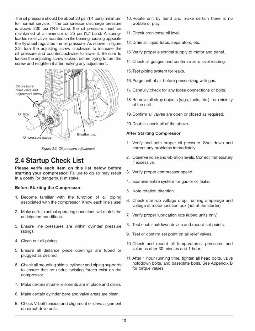
The oil pressure should be about 20 psi (1.4 bars) minimum for normal service. If the compressor discharge pressure is above 200 psi (14.8 bars), the oil pressure must be maintained at a minimum of 25 psi (1.7 bars). A spring-loaded relief valve mounted on the bearing housing opposite the flywheel regulates the oil pressure. As shown in figure 2.3, turn the adjusting screw clockwise to increase the oil pressure and counterclockwise to lower it. Be sure to loosen the adjusting screw locknut before trying to turn the screw and retighten it after making any adjustment.
Oil �lter
Oil pressure gaugeBreather cap
Oil pressurerelief valve and adjustment screw
Figure 2.3: Oil pressure adjustment
2.4 startup Check Listplease verify each item on this list below before starting your compressor! Failure to do so may result in a costly (or dangerous) mistake.
before starting the Compressor
1. Become familiar with the function of all piping associated with the compressor. Know each line’s use!
2. Make certain actual operating conditions will match the anticipated conditions.
3. Ensure line pressures are within cylinder pressure ratings.
4. Clean out all piping.
5. Ensure all distance piece openings are tubed or plugged as desired.
6. Check all mounting shims, cylinder and piping supports to ensure that no undue twisting forces exist on the compressor.
7. Make certain strainer elements are in place and clean.
8. Make certain cylinder bore and valve areas are clean.
9. Check V-belt tension and alignment or drive alignment on direct drive units.
10. Rotate unit by hand and make certain there is no wobble or play.
11. Check crankcase oil level.
12. Drain all liquid traps, separators, etc.
13. Verify proper electrical supply to motor and panel.
14. Check all gauges and confirm a zero level reading.
15. Test piping system for leaks.
16. Purge unit of air before pressurizing with gas.
17. Carefully check for any loose connections or bolts.
18. Remove all stray objects (rags, tools, etc.) from vicinity of the unit.
19. Confirm all valves are open or closed as required.
20. Double-check all of the above.
After starting Compressor
1. Verify and note proper oil pressure. Shut down and correct any problems immediately.
2. Observe noise and vibration levels. Correct immediately if excessive.
3. Verify proper compressor speed.
4. Examine entire system for gas or oil leaks.
5. Note rotation direction.
6. Check start-up voltage drop, running amperage and voltage at motor junction box (not at the starter).
7. Verify proper lubrication rate (lubed units only).
8. Test each shutdown device and record set points.
9. Test or confirm set point on all relief valves.
10. Check and record all temperatures, pressures and volumes after 30 minutes and 1 hour.
11. After 1 hour running time, tighten all head bolts, valve holddown bolts, and baseplate bolts. See Appendix B for torque values.
10
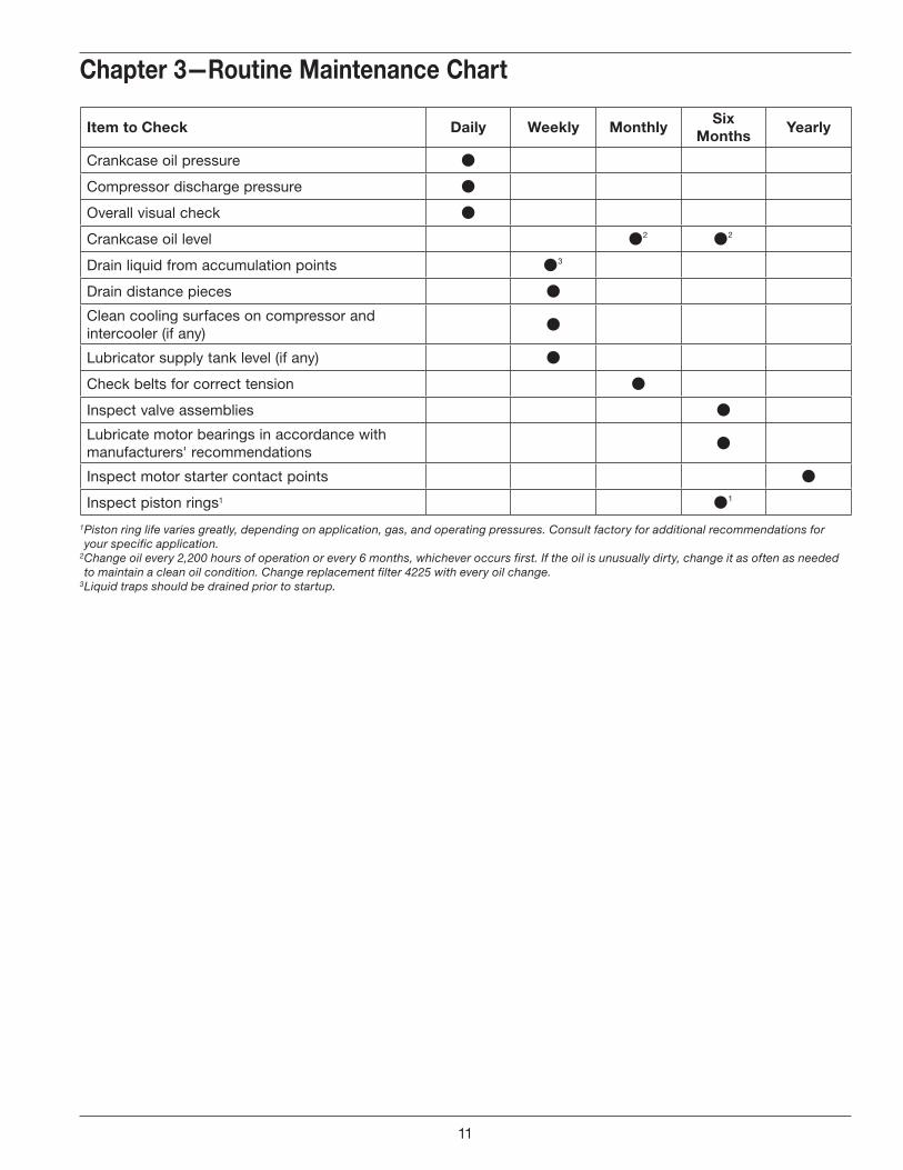
item to Check daily Weekly monthlysix
monthsYearly
Crankcase oil pressure
Compressor discharge pressure
Overall visual check
Crankcase oil level 2 2
Drain liquid from accumulation points 3
Drain distance pieces
Clean cooling surfaces on compressor and intercooler (if any)
Lubricator supply tank level (if any)
Check belts for correct tension
Inspect valve assemblies
Lubricate motor bearings in accordance with manufacturers' recommendations
Inspect motor starter contact points
Inspect piston rings1 1
1 Piston ring life varies greatly, depending on application, gas, and operating pressures. Consult factory for additional recommendations for your specific application.
2 Change oil every 2,200 hours of operation or every 6 months, whichever occurs first. If the oil is unusually dirty, change it as often as needed to maintain a clean oil condition. Change replacement filter 4225 with every oil change.
3 Liquid traps should be drained prior to startup.
Chapter 3—routine maintenance Chart
11
CAutiOn: Always relieve pressure in the unit before attempting any repairs. After repair, the unit should be pressure tested and checked for leaks at all joints and gasket surfaces.
If routine maintenance is performed as listed in chapter 3, repair service on your Corken gas compressor is generally limited to replacing valves or piston rings. When it comes time to order replacement parts, be sure to consult the part details appendix in the back of this Installation, Operation & Maintenance (IOM) manual for a complete list of part numbers and descriptions.
4.1 valvesTest the compressor valves by closing the inlet piping valves while the unit is running; however, do not allow the machine to operate in this way very long. If the inlet pressure gauge does not drop to zero almost immediately, one or more of the valves is probably damaged or dirty. However, it is possible for the pressure gauge itself to be faulty.
In most cases, if a valve or gasket is leaking, it will create more heat. On a single-stage compressor, you may be able to compare the operating temperatures of the two suction or discharge valves and cover plates to each other. If a valve or gasket is leaking, it will have a higher operating temperature. NOTE: This method will not be suitable for two-stage compressors if each stage does not have more than one valve.
Each suction and/or discharge valve assembly is easily removed as a unit for inspection. If any part of the valve assembly is broken, the valve assembly should be replaced. See valve assembly parts details in the Appendix E for a complete list of part numbers and descriptions.
If a valve is leaking due to dirt or any other foreign material that keeps the valve plate and seat from sealing, the valve may be cleaned and reused. New valve gaskets and O-rings should be used to assure a good seal.
The valve holddown assemblies and valve assemblies on the following pages show the various specifications used on models 791 and 891 compressors. Since more than one suction valve arrangement is available for each model of compressor, it is necessary to know your complete model number so you can identify the valve type specification number (see example listed below).
Model number D891AM 4 FBANSNN
Valve type = spec 4
Chapter 4—routine service and repair proceduresvalve inspection and/or replacement
Before removing and inspecting the valves, begin by depressurizing and purging (if necessary) the unit.
disassembly
1. Unscrew the valve cap and remove the O-ring.
2. Remove the valve cover plate, O-ring and holddown screw by removing each of the four bolts. The holddown screw is easily removed with the special wrench supplied with your compressor.
3. After the cover plate and O-ring have been removed, the valve cage, valve assembly and valve gasket can be lifted out.
4. Inspect valves for breakage, corrosion, debris and scratches on the valve plate. In many cases, valves may simply be cleaned and reinstalled. If the valves show any damage, they should be repaired or replaced. Replacement is usually preferable although repair parts are available. If valve plates are replaced, seats should also be lapped until they are perfectly smooth. If more than .005 of an inch must be removed to achieve a smooth surface, the valve should be discarded. If plates are replaced without relapping the seat, rapid wear and leakage may occur.
Assembly
1. Insert metal valve gasket into the suction and/or discharge opening of the head. The metal valve gasket should always be replaced when the valve is reinstalled.
2. Insert cleaned or new valve assembly. Make sure the suction and discharge valves are in the proper suction and discharge opening in the head.
3. Insert the valve cage.
4. Replace the O-ring and valve cover plate. Torque the bolts to the value listed in Appendix B. CAUTION: Be sure the holddown screw has been removed.
5. To ensure the valve gasket is properly seated, insert the holddown screw and tighten to the value listed in Appendix B. NOTE: Gaskets and O-rings are not normally reusable.
6. Replace the O-ring and valve cap and tighten to the value listed in Appendix B.
7. Check bolts and valve holddown screws after first week of operation. Re-torque if necessary. See Appendix B for torque values.
12
rings should be replaced, measure the radial thickness and compare it to the chart in Appendix B.
4.4 piston replacement1. To replace the pistons, depressurize the compressor
and purge if necessary.
2. Remove the compressor cylinder cap, head and cylinder (see section 4.2).
3. Remove the piston cap by loosening and removing the socket head bolts holding the piston cap to the piston (see figure 4.3).
4. Next, remove the lock nut and lift the piston off the end of the piston rod.
5. Check the thrust washer and shims for damage and replace if necessary.
6. Before installing the new piston, measure the thickness of the existing shims.
7. Replace the cylinder.
8. Install the piston with the same thickness of shims as before, and with new piston rings and expanders.
9. Now remove a lower valve and measure dimension “Y” at the bottom of the piston shown in Appendix E—Piston Assembly Details. If this measurement does not fall within the tolerances listed in the piston assembly details (Appendix E), remove the piston, adjust the shims as necessary and remeasure the “Y” dimension.
10. When the piston is properly shimmed, tighten the lock nut as shown in Appendix B.
11. Replace the piston cap with the same thickness of shims as before.
12. Reinstall the piston cap and cylinder head.
13. Now remove an upper valve and measure dimension “X” at the top of the piston shown in Appendix E—Piston Assembly Details. If this measurement does not fall within the tolerances in Appendix E, remove the cylinder head and piston cap and adjust the shims as necessary. Repeat the steps and measure the “X” dimension again.
14. When the piston cap is properly shimmed, tighten the socket head bolts in an alternating sequence. Torque socket head bolt to the values listed in Appendix B.
15. Replace the previously removed valves. Best results will be obtained if new valve gaskets are used.
16. Follow standard startup procedures.
4.2 headsA compressor cylinder cap and head very seldom requires replacement if the compressor is properly maintained. The primary cause of damage to a cylinder cap or head is corrosion and the entry of solid debris or liquid into the compression chamber. Improper storage can also result in corrosion damage to the cylinder cap and heads (for proper storage instructions see chapter 5).
Many compressor repair operations require removal of the cylinder cap and heads. While the compressor is disassembled, special care should be taken to avoid damage or corrosion. If the compressor is to be left open for more than a few hours, bare metal surfaces should be coated with rust preventative.
When reassembling the compressor, make sure the bolts are retightened per the torque values listed in Appendix B.
4.3 piston rings and piston ring expanders
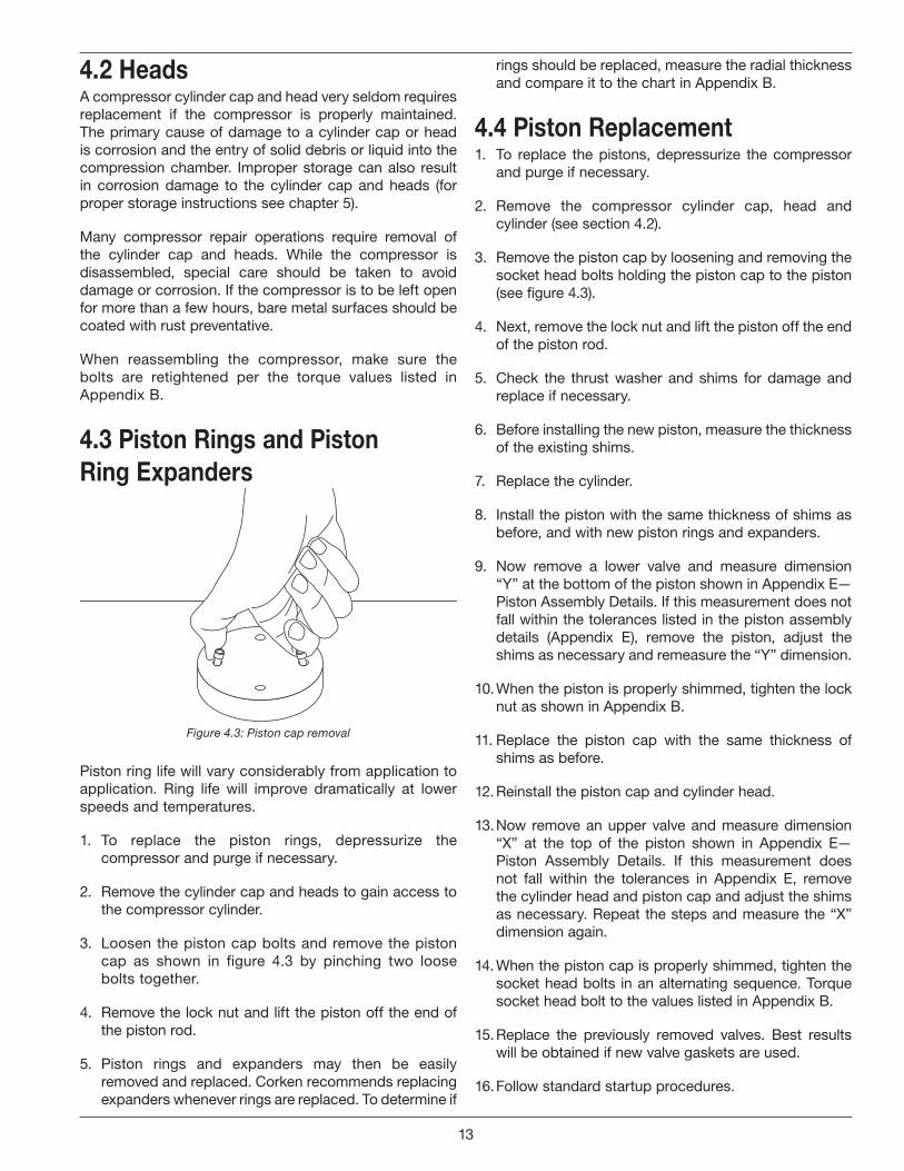
Figure 4.3: Piston cap removal
Piston ring life will vary considerably from application to application. Ring life will improve dramatically at lower speeds and temperatures.
1. To replace the piston rings, depressurize the compressor and purge if necessary.
2. Remove the cylinder cap and heads to gain access to the compressor cylinder.
3. Loosen the piston cap bolts and remove the piston cap as shown in figure 4.3 by pinching two loose bolts together.
4. Remove the lock nut and lift the piston off the end of the piston rod.
5. Piston rings and expanders may then be easily removed and replaced. Corken recommends replacing expanders whenever rings are replaced. To determine if
13
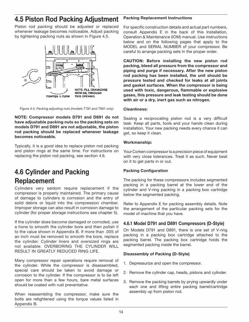
4.5 piston rod packing AdjustmentPiston rod packing should be adjusted or replaced whenever leakage becomes noticeable. Adjust packing by tightening packing nuts as shown in Figure 4.5.
Figure 4.5: Packing adjusting nuts (models T791 and T891 only)
nOte: Compressor models d791 and d891 do not have adjustable packing nuts so the packing sets on models d791 and d891 are not adjustable, the piston rod packing should be replaced whenever leakage becomes noticeable.
Typically, it is a good idea to replace piston rod packing and piston rings at the same time. For instructions on replacing the piston rod packing, see section 4.6.
4.6 Cylinder and packing replacementCylinders very seldom require replacement if the compressor is properly maintained. The primary cause of damage to cylinders is corrosion and the entry of solid debris or liquid into the compression chamber. Improper storage can also result in corrosion damage to cylinder (for proper storage instructions see chapter 5).
If the cylinder does become damaged or corroded, use a hone to smooth the cylinder bore and then polish it to the value shown in Appendix B. If more than .005 of an inch must be removed to smooth the bore, replace the cylinder. Cylinder liners and oversized rings are not available. OVERBORING THE CYLINDER WILL RESULT IN GREATLY REDUCED RING LIFE.
Many compressor repair operations require removal of the cylinder. While the compressor is disassembled, special care should be taken to avoid damage or corrosion to the cylinder. If the compressor is to be left open for more than a few hours, bare metal surfaces should be coated with rust preventative.
When reassembling the compressor, make sure the bolts are retightened using the torque values listed in Appendix B.
packing replacement instructions
For specific construction details and actual part numbers, consult Appendix E in the back of this Installation, Operation & Maintenance (IOM) manual. Use instructions below and on the following pages that apply to the MODEL and SERIAL NUMBER of your compressor. Be careful to arrange packing sets in the proper order.
CAutiOn: before installing the new piston rod packing, bleed all pressure from the compressor and piping and purge if necessary. After the new piston rod packing has been installed, the unit should be pressure tested and checked for leaks at all joints and gasket surfaces. When the compressor is being used with toxic, dangerous, flammable or explosive gases, this pressure and leak testing should be done with air or a dry, inert gas such as nitrogen.
Cleanliness:
Sealing a reciprocating piston rod is a very difficult task. Keep all parts, tools and your hands clean during installation. Your new packing needs every chance it can get, so keep it clean.
Workmanship:
Your Corken compressor is a precision piece of equipment with very close tolerances. Treat it as such. Never beat on it to get parts in or out.
packing Configuration
The packing for these compressors includes segmented packing in a packing barrel at the lower end of the cylinder and V-ring packing in a packing box cartridge below the segmented packing.
Refer to Appendix E for packing assembly details. Note the arrangement of the particular packing sets for the model of machine that you have.
4.6.1 model d791 and d891 Compressors (d-style)On Models D791 and D891, there is one set of V-ring packing in a packing box cartridge attached to the packing barrel. The packing box cartridge holds the segmented packing inside the barrel.
disassembly of packing (d-style)
1. Depressurize and open the compressor.
2. Remove the cylinder cap, heads, pistons and cylinder.
3. Remove the packing barrels by prying upwardly under each one and lifting entire packing barrel/cartridge assembly up from piston rod.
14
4. Remove the four socket head screws that hold the packing box cartridge to the barrel.
5. Remove segmented packing and cups from barrel.
6. Remove lower retainer ring, washers, packing spring and old V-ring packing from packing box cartridge.
Assembly of packing (d-style)
1. Replace packing as required. The segmented packing and cups are located in the packing barrel while the V-ring packing is located in the packing box cartridge. nOte: Always use new O-rings when replacing the packing.
2. V-ring packing set:
nOte: the instructions below are for packing specification “J”. depending on the packing specification used in your compressor, the order of assembly for the packing rings, v-ring packing, washers and packing spring will vary. refer to Appendix e to view the v-ring packing arrangements and follow the order of assembly and v-ring direction. if you do not know the packing arrangement used in your compressor, refer to the model number identification codes listed in Appendix A.
a. Clean and lightly oil the packing area inside the packing box cartridge.
b. Insert the oil deflector ring through the bottom opening of the packing box cartridge.
c. Insert the first retainer ring followed by a washer.
d. Insert the packing spring followed by another washer.
e. Insert a male packing ring followed by four V-rings and one female packing ring. nOte: insert packing rings and v-rings one at a time. refer to Appendix e for the proper direction of the male and female packing rings and v-rings.
f. Lastly, insert the final washer. Push in on the washer and install the second retainer ring.
3. Segmented packing:
nOte: the instructions below are for packing specification “J”. depending on the packing specification used in your compressor, the order of assembly for the segmented packing arrangement (radial or tangent) will vary. refer to Appendix e to view the segmented packing arrangements. if you do not know the packing arrangement used in your compressor, refer to the model number identification codes listed in Appendix A.
a. Clean the segmented packing cups and the area inside the packing barrel.
b. Insert the segmented packing cups, segmented packing pairs and backup rings one at a time in the order shown in Appendix E.
c. Reattach the packing box cartridge to the packing barrel using the four socket head screws.
4. Install three O-rings on the packing barrel and packing box cartridge as shown in the D-Style Crosshead Guide Assembly Details in Appendix E.
5. Install packing installation cone part number 3905 over the threaded end of the piston rod.
6. Carefully install barrel/cartridge assemblies over the piston rods, noting the alignment of the barrels as they sit on the crosshead guide. The valve scallops on the barrels must align properly with the valves in the cylinder.
7. Remove packing installation cone.
8. Replace pistons, cylinders, heads and cylinder cap. See details in Section 4.4 for proper assembly of pistons.
9. Rotate unit by hand to ensure proper assembly.
4.6.2 model t791 and t891 Compressors (t-style)On Models T791 and T891 there are two sets of V-ring packing in a separate packing box cartridge held in the crosshead guide by a cartridge holddown screw. A packing adapter holds the segmented packing inside the packing barrel.
disassembly of packing (t-style)
1. Depressurize and open the compressor.
2. Remove the cylinder cap, heads, pistons and cylinder.
3. Remove the packing barrels.
4. Remove the four socket head screws that hold packing adapter to the barrel.
5. Remove segmented packing and cups from barrel.
6. Remove cartridge holddown screws with special wrench supplied with the compressor, and remove cages and packing box cartridges.
7. On the lower V-ring packing set, remove adjusting screw, washers, packing spring and old packing from each packing box cartridge.
8. On the middle V-ring packing set, remove upper retainer ring, washers, packing spring and old packing from each packing box cartridge.
15
Assembly of packing (t-style)
1. Replace packing as required. The segmented packing and cups are located in the packing barrel while the V-ring packing is located in the packing box cartridge. nOte: Always use new O-rings when replacing the packing.
2. Lower V-ring packing set:
nOte: the instructions below are for packing specification “g”. depending on the packing specification used in your compressor, the order of assembly for the packing rings, v-ring packing, washers and packing spring will vary. refer to Appendix e to view the v-ring packing arrangements and follow the order of assembly and v-ring direction. if you do not know the packing arrangement used in your compressor, refer to the model number identification codes listed in Appendix A.
a. Clean and lightly oil the packing area inside the packing box cartridge.
b. Insert the first retainer ring followed by a washer through the bottom of the packing box cartridge.
c. Insert the packing spring followed by another washer.
d. Insert a male packing ring followed by four V-rings and one female packing ring. nOte: insert packing rings and v-rings one at a time. refer to Appendix e for the proper direction of the packing rings and v-rings.
e. Lastly, install and tightened the adjusting screw until the PTFE locking device located on the side of the adjusting screw is engaged with the first thread of the packing box cartridge. DO NOT OVER TIGHTEN! The PTFE locking device should engage (slightly bent) the first thread but not break off.
3. Middle V-ring packing set:
a. Clean and lightly oil the packing area inside the packing box cartridge.
b. Insert the second retainer ring followed by a washer through the top of the packing box cartridge.
c. Insert a female packing ring followed by four V-rings and one male packing ring. nOte: insert packing rings and v-rings one at a time. refer to Appendix e for the proper direction of the male and female packing rings and v-rings.
d. Insert a washer and a packing spring followed by another washer.
e. Lastly, push in on the washer and insert the third retainer ring.
f. Install two O-rings on the packing box cartridge as shown in the T-Style Crosshead Guide Assembly Details in Appendix E.
4. Segmented packing:
nOte: the instructions below are for packing specification “g”. depending on the packing specification used in your compressor, the order of assembly for the segmented packing arrangement (radial or tangent) will vary. refer to Appendix e to view the segmented packing arrangements. if you do not know the packing arrangement used in your compressor, refer to the model number identification codes listed in Appendix A.
a. Clean the segmented packing cups and the area inside the packing barrel.
b. Insert the segmented packing cups, segmented packing pairs and backup rings one at a time in the order shown in Appendix E.
c. Reattach the packing adapter to the packing barrel using the four socket head screws.
d. Install two O-rings on the packing barrel as shown in the T-Style Crosshead Guide Assembly Details in Appendix E.
5. Install packing installation cone part number 3905 over the threaded end of the piston rod.
6. Before installing the packing box cartridge over the packing cone and piston rod, you must insert the oil deflector ring through the side opening of the packing box cartridge. The oil deflector ring should rest on top of the lower packing set. Make sure the oil deflector ring is centered over the piston rod opening before sliding packing cartridge over the installation cone and piston rod.
7. Install cages.
8. Install and tighten holddown screws with special wrench.
9. Install packing barrels, noting the alignment of the barrels as they sit on the crosshead guide. The valve scallops on the barrels must align properly with the valves in the cylinder.
10. Remove packing installation cone.
11. Replace cylinder, pistons, heads and cylinder cap. See details in Section 4.4 for proper assembly of pistons.
12. Rotate unit by hand to ensure proper assembly.
16
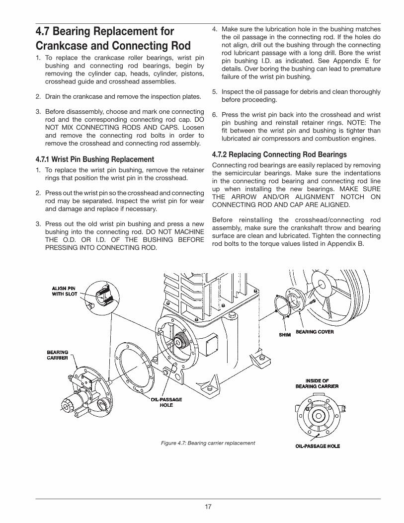
Figure 4.7: Bearing carrier replacement
4.7 bearing replacement for Crankcase and Connecting rod1. To replace the crankcase roller bearings, wrist pin
bushing and connecting rod bearings, begin by removing the cylinder cap, heads, cylinder, pistons, crosshead guide and crosshead assemblies.
2. Drain the crankcase and remove the inspection plates.
3. Before disassembly, choose and mark one connecting rod and the corresponding connecting rod cap. DO NOT MIX CONNECTING RODS AND CAPS. Loosen and remove the connecting rod bolts in order to remove the crosshead and connecting rod assembly.
4.7.1 Wrist pin bushing replacement1. To replace the wrist pin bushing, remove the retainer
rings that position the wrist pin in the crosshead.
2. Press out the wrist pin so the crosshead and connecting rod may be separated. Inspect the wrist pin for wear and damage and replace if necessary.
3. Press out the old wrist pin bushing and press a new bushing into the connecting rod. DO NOT MACHINE THE O.D. OR I.D. OF THE BUSHING BEFORE PRESSING INTO CONNECTING ROD.
4. Make sure the lubrication hole in the bushing matches the oil passage in the connecting rod. If the holes do not align, drill out the bushing through the connecting rod lubricant passage with a long drill. Bore the wrist pin bushing I.D. as indicated. See Appendix E for details. Over boring the bushing can lead to premature failure of the wrist pin bushing.
5. Inspect the oil passage for debris and clean thoroughly before proceeding.
6. Press the wrist pin back into the crosshead and wrist pin bushing and reinstall retainer rings. NOTE: The fit between the wrist pin and bushing is tighter than lubricated air compressors and combustion engines.
4.7.2 replacing Connecting rod bearingsConnecting rod bearings are easily replaced by removing the semicircular bearings. Make sure the indentations in the connecting rod bearing and connecting rod line up when installing the new bearings. MAKE SURE THE ARROW AND/OR ALIGNMENT NOTCH ON CONNECTING ROD AND CAP ARE ALIGNED.
Before reinstalling the crosshead/connecting rod assembly, make sure the crankshaft throw and bearing surface are clean and lubricated. Tighten the connecting rod bolts to the torque values listed in Appendix B.
17
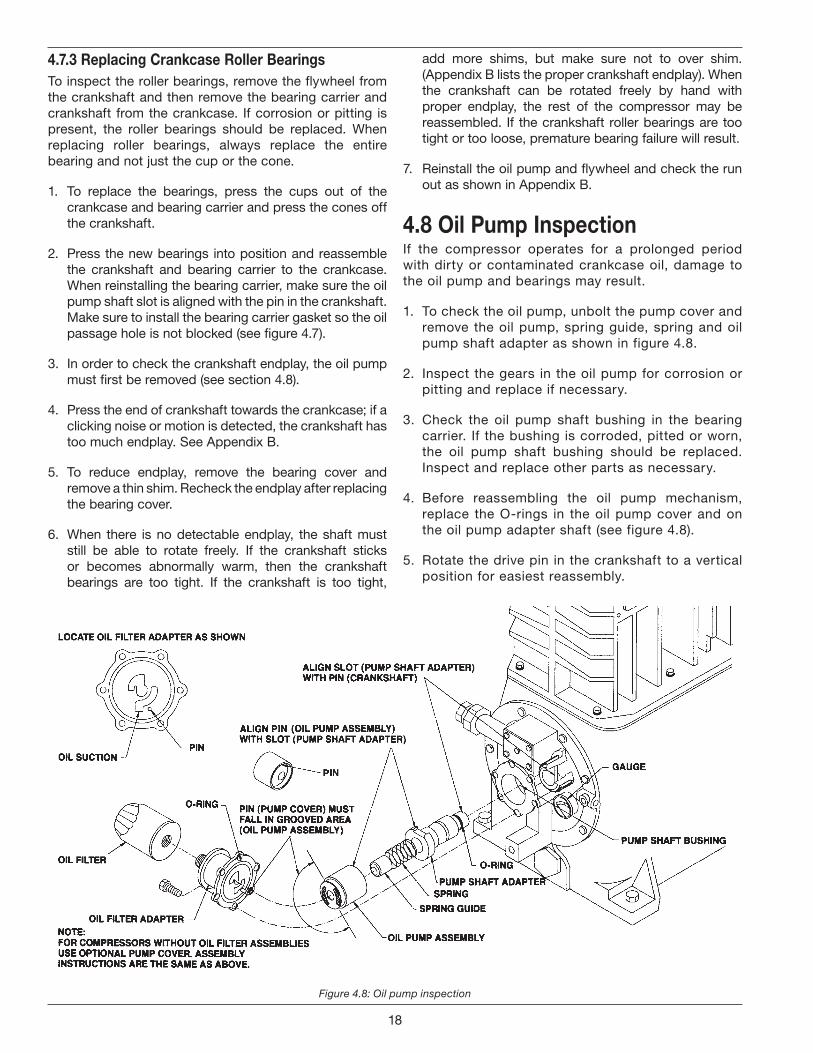
Figure 4.8: Oil pump inspection
4.7.3 replacing Crankcase roller bearingsTo inspect the roller bearings, remove the flywheel from the crankshaft and then remove the bearing carrier and crankshaft from the crankcase. If corrosion or pitting is present, the roller bearings should be replaced. When replacing roller bearings, always replace the entire bearing and not just the cup or the cone.
1. To replace the bearings, press the cups out of the crankcase and bearing carrier and press the cones off the crankshaft.
2. Press the new bearings into position and reassemble the crankshaft and bearing carrier to the crankcase. When reinstalling the bearing carrier, make sure the oil pump shaft slot is aligned with the pin in the crankshaft. Make sure to install the bearing carrier gasket so the oil passage hole is not blocked (see figure 4.7).
3. In order to check the crankshaft endplay, the oil pump must first be removed (see section 4.8).
4. Press the end of crankshaft towards the crankcase; if a clicking noise or motion is detected, the crankshaft has too much endplay. See Appendix B.
5. To reduce endplay, remove the bearing cover and remove a thin shim. Recheck the endplay after replacing the bearing cover.
6. When there is no detectable endplay, the shaft must still be able to rotate freely. If the crankshaft sticks or becomes abnormally warm, then the crankshaft bearings are too tight. If the crankshaft is too tight,
add more shims, but make sure not to over shim. (Appendix B lists the proper crankshaft endplay). When the crankshaft can be rotated freely by hand with proper endplay, the rest of the compressor may be reassembled. If the crankshaft roller bearings are too tight or too loose, premature bearing failure will result.
7. Reinstall the oil pump and flywheel and check the run out as shown in Appendix B.
4.8 Oil pump inspectionIf the compressor operates for a prolonged period with dirty or contaminated crankcase oil, damage to the oil pump and bearings may result.
1. To check the oil pump, unbolt the pump cover and remove the oil pump, spring guide, spring and oil pump shaft adapter as shown in figure 4.8.
2. Inspect the gears in the oil pump for corrosion or pitting and replace if necessary.
3. Check the oil pump shaft bushing in the bearing carrier. If the bushing is corroded, pitted or worn, the oil pump shaft bushing should be replaced. Inspect and replace other parts as necessary.
4. Before reassembling the oil pump mechanism, replace the O-rings in the oil pump cover and on the oil pump adapter shaft (see figure 4.8).
5. Rotate the drive pin in the crankshaft to a vertical position for easiest reassembly.
18
6. Insert the shaft adapter so it engages the drive pin.
7. Next, insert the spring, spring guide and oil pump assembly. The pin on the oil pump must align with the slot in the shaft adapter.
8. Install the pump cover so the pin on the case is in the opening on the oil pump assembly as shown in figure 4.8. When you are sure the pin is properly aligned, install the cover bolts finger tight. If alignment is correct, the pump cover will mount flush to the bearing carrier. If it does not, re-check the pin alignment.
9. Tighten the bolts in an alternating sequence. See section 2.3 for directions on oil pressure adjustment.
10. Finally, rotate the crankshaft by hand to ensure smooth operation. Then rotate it in opposite directions, listening for a click, which indicates proper alignment of the oil pump’s pins and slots.
Chapter 5—extended storage proceduresFollowing a few simple procedures will greatly minimize the risk of the unit becoming corroded and damaged. Corken recommends the following precautions to protect the compressor during storage:
1. Drain the crankcase oil and refill with rust inhibiting oil.
2. Operate for a few minutes while fogging oil into the compressor suction.
3. Relieve V-belt tension.
4. Plug all openings to prevent entry of insects and moisture. (The cylinders may also be protected by the use of a vapor phase inhibitor, silica gel, or dry nitrogen gas. If the silica gel is used, hang a tag on the unit indicating that it must be removed before start-up.)
5. Store in a dry area and off the ground if possible.
6. Rotate the flywheel every two weeks if possible.
19
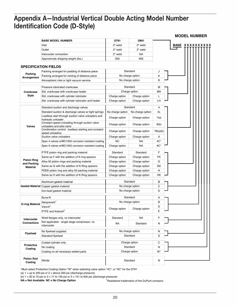
BASE MODEL NUMBER D791 D891Inlet 2" weld 2" weld BASE X X X X X X X X X XOutlet 2" weld 2" weldIntercooler connection 2" weld NAApproximate shipping weight (lbs.) 930 900
SPECIFICATION FIELDSPacking arranged for padding of distance piece JPacking arranged for venting of distance piece KAtmospheric inlet or light vacuum service R
Pressure lubricated crankcase MStd. crankcase with crankcase heater MHStd. crankcase with cylinder lubricator Charge option Charge option LStd. crankcase with cylinder lubricator and heater Charge option Charge option LH
Standard suction and discharge valves 4Standard suction & discharge valves w/ light springs No charge option No charge option 4LLoadless start through suction valve unloaders and hydraulic unloader
Charge option Charge option 7(a)
Constant speed unloading through suction valve unloaders and pilot valve
Charge option Charge option 8(b)
Combination control: loadless starting and constant speed unloading
Charge option Charge option 78(a)(b)
Suction valve unloaders Charge option Charge option 9Spec 4 valves w/MC1002 corrosion resistant coating NC NA 4C*Spec 9 valves w/MC1002 corrosion resistant coating Charge option NA 9C*
PTFE piston ring and packing material Standard Standard FSame as F with the addition of K-ring spacers Charge option Charge option FKAlloy 50 piston rings and packing material Charge option Charge option GSame as G with the addition of K-Ring spacers Charge option Charge option GKPEEK piston ring and alloy 50 packing material Charge option Charge option HSame as H with the addition of K-Ring spacers Charge option Charge option HK
Aluminum gasket material B
MODEL NUMBER
Piston Ring and Packing
Material
Crankcase Style
Charge option
Valves
Standard
Packing Arrangement
StandardNo charge optionNo charge option
Standard
Standard
Aluminum gasket material BCopper gasket material CIron-lead gasket material D
Buna-N ANeoprene®1 BViton®1 DPTFE and Kalrez®1 E
Weld flanges only, no intercooler Standard NA FNot applicable - single stage compressor, no intercooler
NA Standard N
No flywheel supplied NStandard flywheel S
Coated cylinder only CNo coating NCoating on all necessary wetted parts W*
*Must select Protective Coating Option "W" when selecting valve option "4C", or "9C" for the D791(a) 1 = up to 200 psi or 2 = above 200 psi (discharge pressure)(b) 1 = 30 to 70 psi or 2 = 71 to 150 psi or 3 = 151 to 500 psi (discharge pressure)NA = Not Available NC = No Charge Option 1Registered trademarks of the DuPont company.
N
Charge option
O-ring Material
Standard
Charge option Charge option
FlywheelNo charge option
Standard
No charge option
Piston Rod Coating
Protective Coating Standard
Charge option
Nitride Standard
Intercooler Connections
No charge optionGasket MaterialStandard
No charge option
Appendix A—industrial vertical double Acting model number identification Code (d-style)
Appendices
A. vertical double-Acting model number identification Code
20
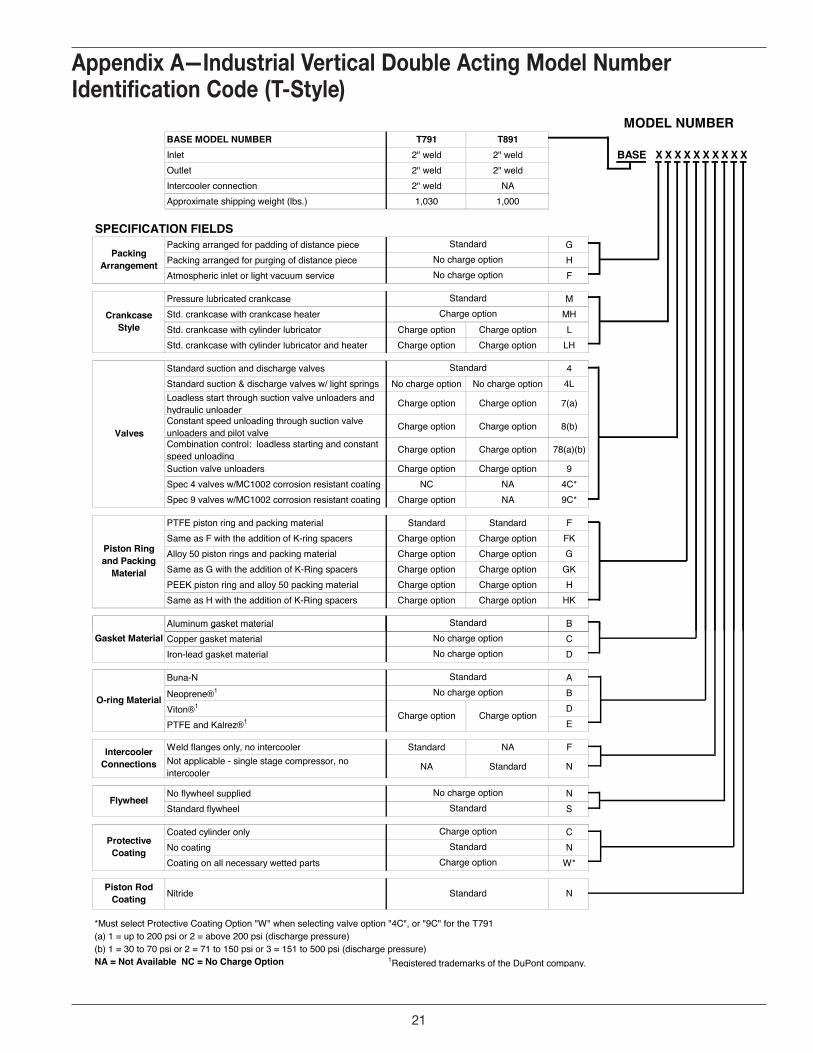
BASE MODEL NUMBER T791 T891Inlet 2" weld 2" weld BASE X X X X X X X X X XOutlet 2" weld 2" weldIntercooler connection 2" weld NAApproximate shipping weight (lbs.) 1,030 1,000
SPECIFICATION FIELDSPacking arranged for padding of distance piece GPacking arranged for purging of distance piece HAtmospheric inlet or light vacuum service F
Pressure lubricated crankcase MStd. crankcase with crankcase heater MHStd. crankcase with cylinder lubricator Charge option Charge option LStd. crankcase with cylinder lubricator and heater Charge option Charge option LH
Standard suction and discharge valves 4Standard suction & discharge valves w/ light springs No charge option No charge option 4LLoadless start through suction valve unloaders and hydraulic unloader
Charge option Charge option 7(a)
Constant speed unloading through suction valve unloaders and pilot valve
Charge option Charge option 8(b)
Combination control: loadless starting and constant speed unloading
Charge option Charge option 78(a)(b)
Suction valve unloaders Charge option Charge option 9Spec 4 valves w/MC1002 corrosion resistant coating NC NA 4C*Spec 9 valves w/MC1002 corrosion resistant coating Charge option NA 9C*
PTFE piston ring and packing material Standard Standard FSame as F with the addition of K-ring spacers Charge option Charge option FKAlloy 50 piston rings and packing material Charge option Charge option GSame as G with the addition of K-Ring spacers Charge option Charge option GKPEEK piston ring and alloy 50 packing material Charge option Charge option HSame as H with the addition of K-Ring spacers Charge option Charge option HK
Aluminum gasket material B
MODEL NUMBER
Packing Arrangement
StandardNo charge optionNo charge option
Piston Ring and Packing
Material
Standard
Crankcase Style
StandardCharge option
Valves
Standard
Aluminum gasket material BCopper gasket material CIron-lead gasket material D
Buna-N ANeoprene®1 BViton®1 DPTFE and Kalrez®1 E
Weld flanges only, no intercooler Standard NA FNot applicable - single stage compressor, no intercooler
NA Standard N
No flywheel supplied NStandard flywheel S
Coated cylinder only CNo coating NCoating on all necessary wetted parts W*
*Must select Protective Coating Option "W" when selecting valve option "4C", or "9C" for the T791(a) 1 = up to 200 psi or 2 = above 200 psi (discharge pressure)(b) 1 = 30 to 70 psi or 2 = 71 to 150 psi or 3 = 151 to 500 psi (discharge pressure)NA = Not Available NC = No Charge Option 1Registered trademarks of the DuPont company.
Gasket MaterialStandard
No charge optionNo charge option
FlywheelNo charge option
Standard
O-ring Material
StandardNo charge option
Charge option Charge option
Intercooler Connections
Piston Rod Coating Nitride Standard N
Protective Coating
Charge optionStandard
Charge option
Appendix A—industrial vertical double Acting model number identification Code (t-style)
21
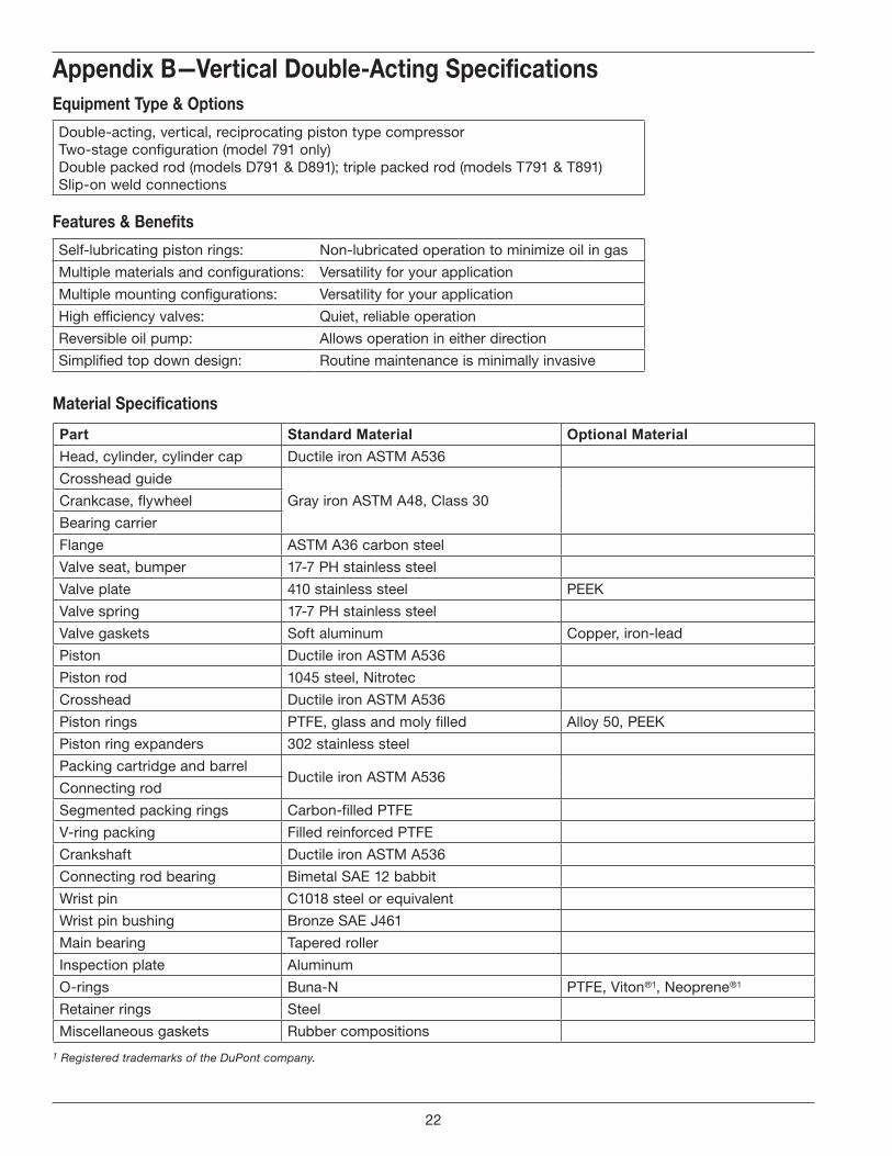
Appendix b—vertical double-Acting specificationsequipment type & Options
Double-acting, vertical, reciprocating piston type compressorTwo-stage configuration (model 791 only)Double packed rod (models D791 & D891); triple packed rod (models T791 & T891)Slip-on weld connections
features & benefits
Self-lubricating piston rings: Non-lubricated operation to minimize oil in gas
Multiple materials and configurations: Versatility for your application
Multiple mounting configurations: Versatility for your application
High efficiency valves: Quiet, reliable operation
Reversible oil pump: Allows operation in either direction
Simplified top down design: Routine maintenance is minimally invasive
Part Standard Material Optional MaterialHead, cylinder, cylinder cap Ductile iron ASTM A536
Crosshead guide
Gray iron ASTM A48, Class 30Crankcase, flywheel
Bearing carrier
Flange ASTM A36 carbon steel
Valve seat, bumper 17-7 PH stainless steel
Valve plate 410 stainless steel PEEK
Valve spring 17-7 PH stainless steel
Valve gaskets Soft aluminum Copper, iron-lead
Piston Ductile iron ASTM A536
Piston rod 1045 steel, Nitrotec
Crosshead Ductile iron ASTM A536
Piston rings PTFE, glass and moly filled Alloy 50, PEEK
Piston ring expanders 302 stainless steel
Packing cartridge and barrelDuctile iron ASTM A536
Connecting rod
Segmented packing rings Carbon-filled PTFE
V-ring packing Filled reinforced PTFE
Crankshaft Ductile iron ASTM A536
Connecting rod bearing Bimetal SAE 12 babbit
Wrist pin C1018 steel or equivalent
Wrist pin bushing Bronze SAE J461
Main bearing Tapered roller
Inspection plate Aluminum
O-rings Buna-N PTFE, Viton®1, Neoprene®1
Retainer rings Steel
Miscellaneous gaskets Rubber compositions
material specifications
1 Registered trademarks of the DuPont company.
b. vertical double-Acting specifications
22
Appendix b—vertical double-Acting specifications
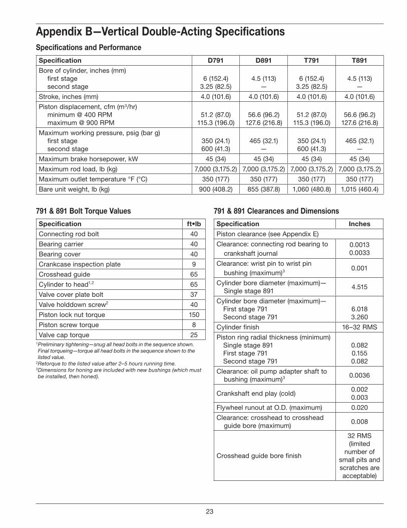
791 & 891 bolt torque values
specifications and performance
1 Preliminary tightening—snug all head bolts in the sequence shown. Final torqueing—torque all head bolts in the sequence shown to the listed value.
2 Retorque to the listed value after 2–5 hours running time.3 Dimensions for honing are included with new bushings (which must be installed, then honed).
specification ft•lb
Connecting rod bolt 40
Bearing carrier 40
Bearing cover 40
Crankcase inspection plate 9
Crosshead guide 65
Cylinder to head1,2 65
Valve cover plate bolt 37
Valve holddown screw2 40
Piston lock nut torque 150
Piston screw torque 8
Valve cap torque 25
specification d791 d891 t791 t891
Bore of cylinder, inches (mm) first stage second stage
6 (152.4) 3.25 (82.5)
4.5 (113) —
6 (152.4) 3.25 (82.5)
4.5 (113) —
Stroke, inches (mm) 4.0 (101.6) 4.0 (101.6) 4.0 (101.6) 4.0 (101.6)
Piston displacement, cfm (m3/hr) minimum @ 400 RPM maximum @ 900 RPM
51.2 (87.0) 115.3 (196.0)
56.6 (96.2) 127.6 (216.8)
51.2 (87.0) 115.3 (196.0)
56.6 (96.2) 127.6 (216.8)
Maximum working pressure, psig (bar g) first stage second stage
350 (24.1) 600 (41.3)
465 (32.1) —
350 (24.1) 600 (41.3)
465 (32.1) —
Maximum brake horsepower, kW 45 (34) 45 (34) 45 (34) 45 (34)
Maximum rod load, lb (kg) 7,000 (3,175.2) 7,000 (3,175.2) 7,000 (3,175.2) 7,000 (3,175.2)
Maximum outlet temperature °F (°C) 350 (177) 350 (177) 350 (177) 350 (177)
Bare unit weight, lb (kg) 900 (408.2) 855 (387.8) 1,060 (480.8) 1,015 (460.4)
791 & 891 Clearances and dimensions
specification inches
Piston clearance (see Appendix E)
Clearance: connecting rod bearing to crankshaft journal
0.0013 0.0033
Clearance: wrist pin to wrist pin bushing (maximum)3 0.001
Cylinder bore diameter (maximum)—Single stage 891
4.515
Cylinder bore diameter (maximum)— First stage 791 Second stage 791
6.018 3.260
Cylinder finish 16–32 RMS
Piston ring radial thickness (minimum) Single stage 891 First stage 791 Second stage 791
0.082 0.155 0.082
Clearance: oil pump adapter shaft to bushing (maximum)3 0.0036
Crankshaft end play (cold)0.002 0.003
Flywheel runout at O.D. (maximum) 0.020
Clearance: crosshead to crosshead guide bore (maximum)
0.008
Crosshead guide bore finish
32 RMS (limited
number of small pits and scratches are acceptable)
23
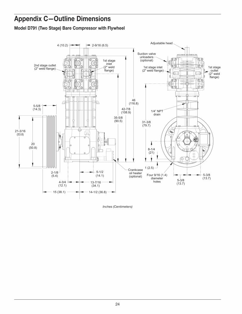
5-5/8(14.3)
21-3/16(53.8)
2-1/8(5.4)
15 (38.1)
4-3/4(12.1)
14-1/2 (36.8)
5-1/2(14.1)
13-7/16(34.1)
4 (10.2) 2-9/16 (6.5)
35-5/8(90.5)
42-7/8(108.9)
46(116.8)
31-3/8(79.7)
8-1/4(21)
1 (2.5)
5-3/8(13.7)
5-3/8(13.7)
Adjustable head
1st stageoutlet
(2" weldflange)
1st stage inlet(2" weld flange)
1st stageinlet
(2" weldflange)
2nd stage outlet(2" weld flange)
Suction valveunloaders(optional)
1/4” NPTdrain
Crankcaseoil heater(optional) Four 9/16 (1.4)
diameterholes
20(50.8)
Appendix C—Outline dimensionsmodel d791 (two stage) bare Compressor with flywheel
Inches (Centimeters)
C. Outline dimensions
24
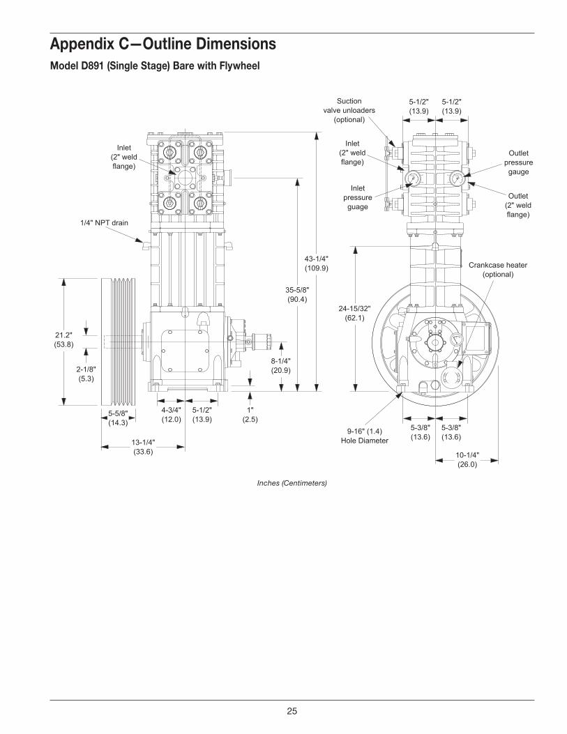
Suctionvalve unloaders
(optional)
Inlet(2" weldflange)
9-16" (1.4)Hole Diameter
Inletpressureguage
Outletpressuregauge
Outlet(2" weldflange)
Crankcase heater(optional)
2-1/8"(5.3)
8-1/4"(20.9)
35-5/8"(90.4)
43-1/4"(109.9)
Inlet(2" weldflange)
1/4" NPT drain
24-15/32"(62.1)
21.2"(53.8)
5-5/8"(14.3)
13-1/4"(33.6)
4-3/4"(12.0)
1"(2.5)
5-1/2"(13.9)
5-3/8"(13.6)
10-1/4"(26.0)
5-3/8"(13.6)
5-1/2"(13.9)
5-1/2"(13.9)
Appendix C—Outline dimensionsmodel d891 (single stage) bare with flywheel
Inches (Centimeters)
25
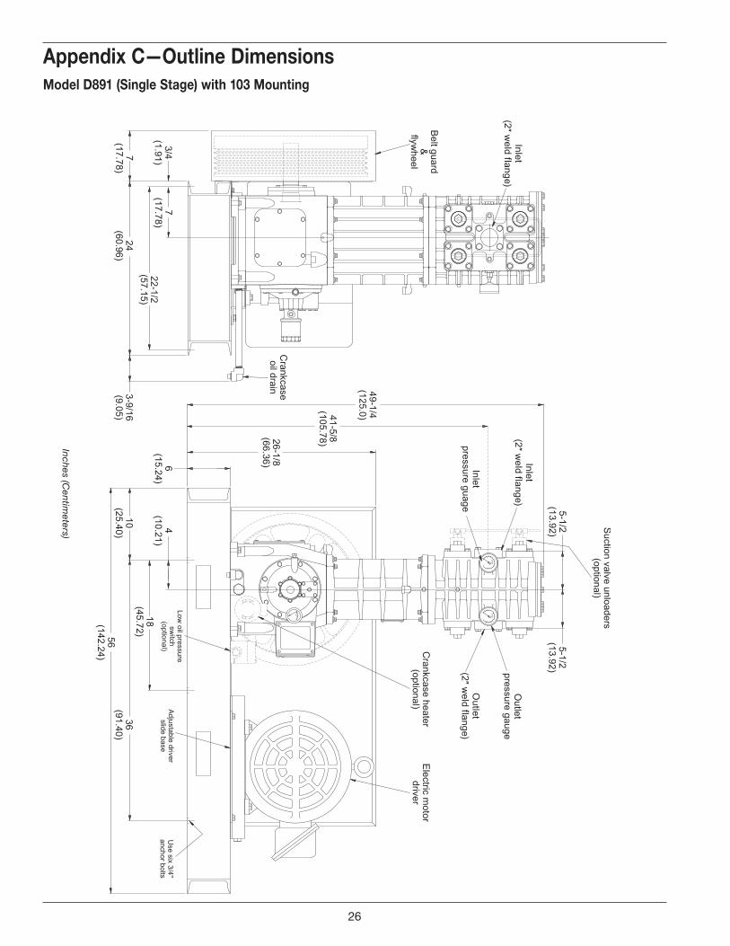
Inlet(2 ″ w
eld flange)
Inlet(2″ w
eld flange)
Outlet
(2″ weld flange)
Appendix C—Outline dimensionsmodel d891 (single stage) with 103 mounting
Inches (Centim
eters)
26
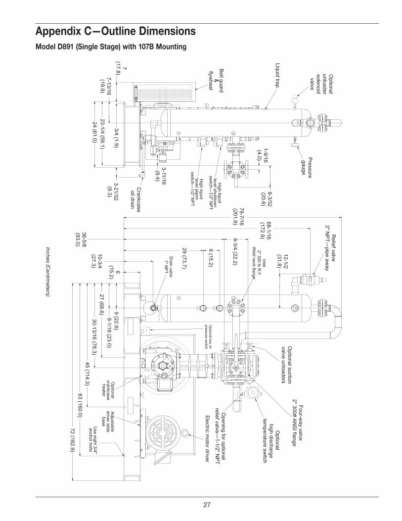
Appendix C—Outline dimensionsmodel d891 (single stage) with 107b mounting
Inches (Centim
eters)
27
CORKENCORKEN
FLOW
CORKEN
72(182.88)
41-21/32(105.81)
9-3/32(23.07)
7-1/16(17.96)
24(60.96)
3-21/32(9.31)
3-23/32(9.45)
6-1/2(16.49)
3/4(1.91)
45(114.30)
63(160.02)
30-5/64(76.41)
22-1/2(57.15)
Low oil
pressure switch
(optional)
Drain valve1" N
PT
Inletpressure
gauge
Outlet 2" w
eld flange
Electric m
otor driver
Outlet pressure gauge
Suction valve
unloaders (optional)
Inlet2" 300# R
Fw
eld neck flange
Relief valve
2" NP
T pipe away
High liquid level
shutdown sw
itch1/2" N
PT
High liquid level
alarm sw
itch1/2" N
PT
Crankcase
oil drain
Belt guard
Crankcaseheater
(optional)
Adjustable driver
slide baseU
seeight 3/4"
anchorbolts
5-15/16(15.09)
10-11/16(27.15)
28-15/16(73.51)
34-15/16(88.75)
40-15/16(103.99)
68(172.72)
12-1/2(31.75)
5-1/2(13.92)
79-13/32(201.69)
9/16(1.43) 9/16
(1.43)
27(68.58)
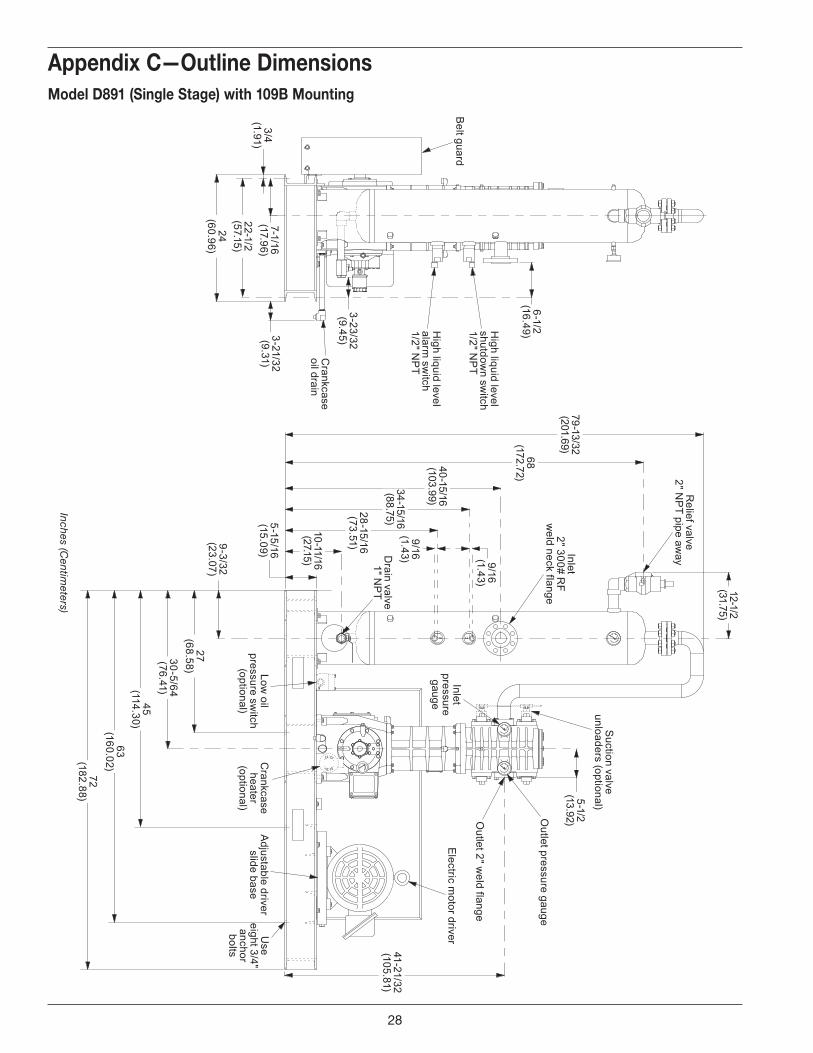
Appendix C—Outline dimensionsmodel d891 (single stage) with 109b mounting
Inches (Centim
eters)
28
2-9/16 (7)
1 (3)
5-3/8(14)
Four 9/16″ (1.4)diameter holes
21-3/16(54)
20 (51)
5-5/8(14)
2-1/8 (5) 13-3/4 (35)
15 (38)
4-3/4(12)
5-1/2 (14)
14-1/2 (37)
43-5/8(111)
50-7/8(129)
54(137)
Crankcaseoil heater(optional)
39-3/8(100)
1/4″ NPTupper
distancepiece
Suction valveunloaders(optional)
4 (10)
8-1/4(21)
1/4″ NPTlower
distancepiece
1st stageoutlet (2″
weld flange)
1st stageinlet (2″
weld flange)
1st stageinlet (2″
weld flange)
2nd stageoutlet (2″
weld flange)
Adjustablehead
5-3/8(14)
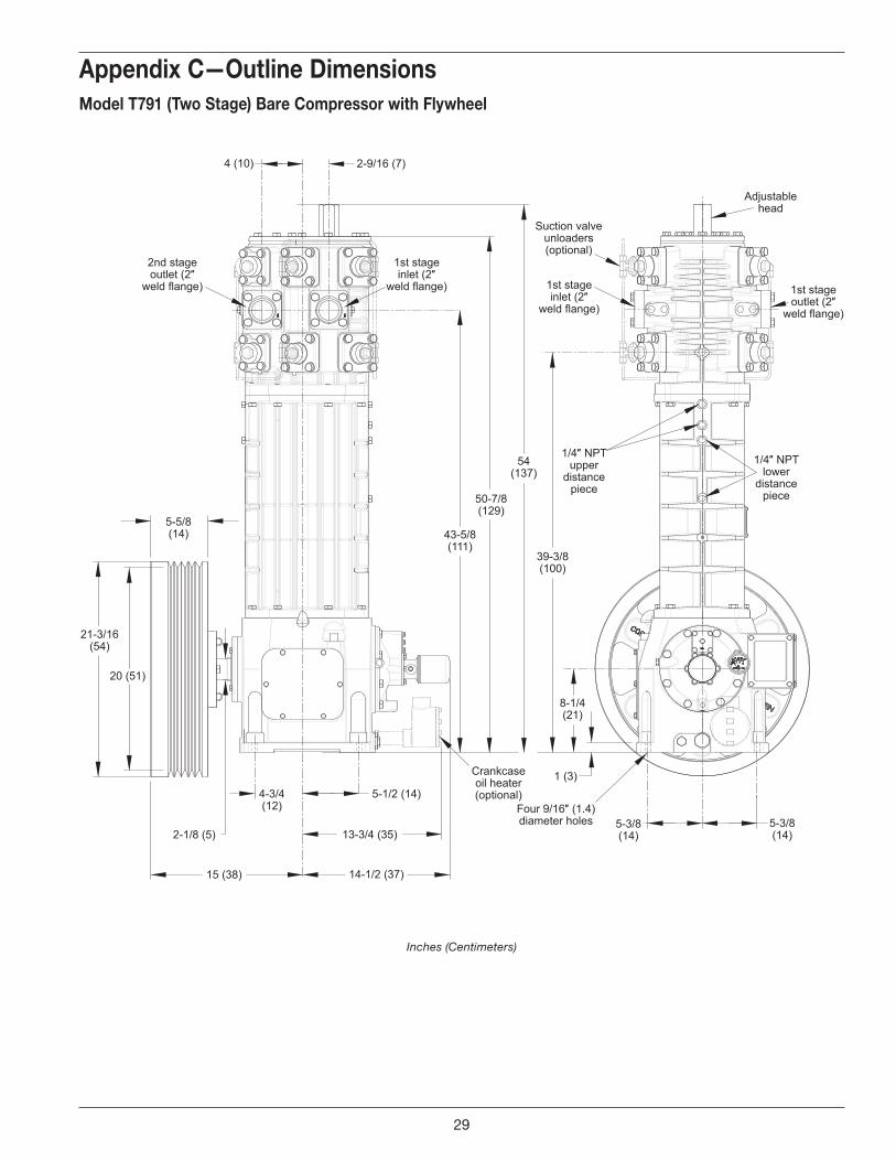
Appendix C—Outline dimensionsmodel t791 (two stage) bare Compressor with flywheel
Inches (Centimeters)
29
5-5/8(14.3)
21-3/16(53.8)
20(50.8)
2-1/8 (5.4)
4-3/4 (12.1)
15 (38.2) 14-1/2 (36.9)
5-1/2 (14.1)
13-5/8 (34.5)
Crankcaseoil heater(optional)
8-1/4(21)
1 (2.5)
5-3/8(13.6)
5-3/8(13.6)
1/4″ upperdistance
piece
51-1/4(130.1)
43-5/8(110.8)
Suction valveunloaders(optional)
5-7/16(13.9)
Inlet (2″ weld flange)
5-7/16(13.9)
Outlet (2″weld flange)
1/4″ NPTlower
distancepiece
Four 9/16″ (1.4)diameter holes
Inlet (2″ weld flange)
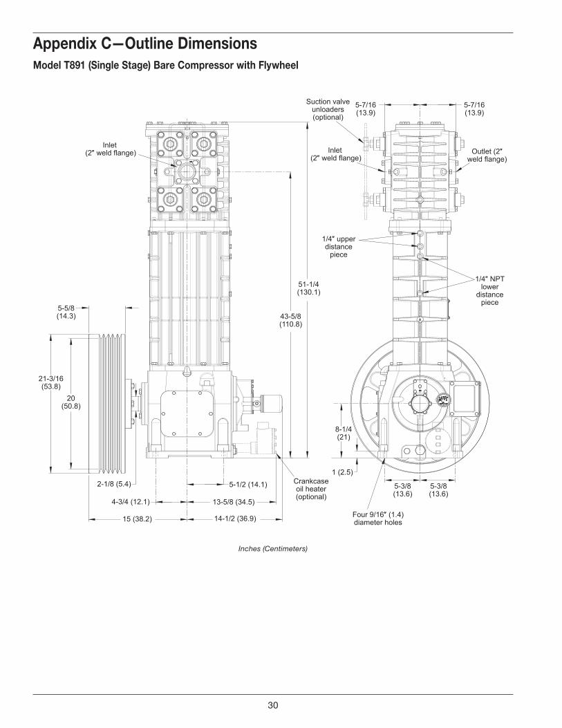
Appendix C—Outline dimensionsmodel t891 (single stage) bare Compressor with flywheel
Inches (Centimeters)
30
Beltguard
Inlet(2″ w
eld flange)
Crankcaseoil drain
24 (60.96)7
(17.78)3-9/16(9.13)
57-1/4(145.34)49-5/8
126.10
31(78.74)
5-3/4(14.61)
1-1/2(3.81)
2(5.08)
Pressure gauge
(Inlet)
Suction valve unloaders
(optional)5-1/2
(13.92)5-1/2
(13.92)
Inlet(2″ w
eld flange)P
ressure gauge(outlet)
Outlet
(2″ weld flange)
Purge connections
(1/4″)
Crankcase heater
(optional)E
lectric motor driver
Low oil pressure sw
itch(optional)
18 (45.72)
4(10.21)
10 (25.40)
56 (142.24)
Adjustable driver slide base
Use six 3/4″
anchor bolts6
(15.24)
36 (91.44)
Purge
connections(1/4″)
22-1/2 (57.15)
3/4(1.91)
7(17.78)
Suction valve unloaders
(optional)
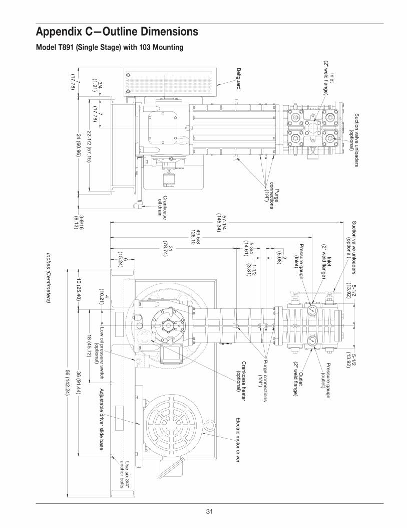
Appendix C—Outline dimensionsmodel t891 (single stage) with 103 mounting
Inches (Centim
eters)
31
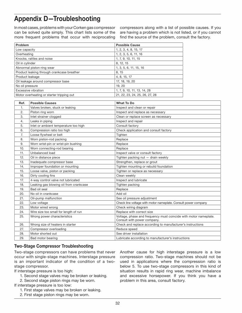
two-stage Compressor troubleshootingTwo-stage compressors can have problems that never occur with single-stage machines. Interstage pressure is an important indicator of the condition of a two-stage compressor.If interstage pressure is too high: 1. Second stage valves may be broken or leaking. 2. Second stage piston rings may be worn.If interstage pressure is too low: 1. First stage valves may be broken or leaking. 2. First stage piston rings may be worn.
In most cases, problems with your Corken gas compressor can be solved quite simply. This chart lists some of the more frequent problems that occur with reciprocating
compressors along with a list of possible causes. If you are having a problem which is not listed, or if you cannot find the source of the problem, consult the factory.
Appendix d—troubleshooting
problem possible CauseLow capacity 1, 2, 3, 4, 8, 15, 17Overheating 1, 2, 3, 5, 6, 11, 16Knocks, rattles and noise 1, 7, 9, 10, 11, 15Oil in cylinder 8, 12, 15Abnormal piston-ring wear 1, 3, 5, 6, 11, 15, 16Product leaking through crankcase breather 8, 15Product leakage 4, 8, 15, 17Oil leakage around compressor base 17, 18, 19, 20No oil pressure 19, 20Excessive vibration 1, 7, 9, 10, 11, 13, 14, 28Motor overheating or starter tripping out 21, 22, 23, 24, 25, 26, 27, 28
ref. possible Causes What to do1. Valves broken, stuck or leaking Inspect and clean or repair2. Piston ring worn Inspect and replace as necessary3. Inlet strainer clogged Clean or replace screen as necessary4. Leaks in piping Inspect and repair5. Inlet or ambient temperature too high Consult factory6. Compression ratio too high Check application and consult factory7. Loose flywheel or belt Tighten8. Worn piston-rod packing Replace9. Worn wrist-pin or wrist-pin bushing Replace10. Worn connecting-rod bearing Replace11. Unbalanced load Inspect valve or consult factory12. Oil in distance piece Tighten packing nut — drain weekly13. Inadequate compressor base Strengthen, replace or grout14. Improper foundation or mounting Tighten mounting or rebuild foundation15. Loose valve, piston or packing Tighten or replace as necessary16. Dirty cooling fins Clean weekly17. 4-way control valve not lubricated Inspect and lubricate18. Leaking gas blowing oil from crankcase Tighten packing19. Bad oil seal Replace20. No oil in crankcase Add oil21. Oil-pump malfunction See oil pressure adjustment22. Low voltage Check line voltage with motor nameplate. Consult power company23. Motor wired wrong Check wiring diagram24. Wire size too small for length of run Replace with correct size25. Wrong power characteristics Voltage, phase and frequency must coincide with motor nameplate.
Consult with power company.26. Wrong size of heaters in starter Check and replace according to manufacturer’s instructions27. Compressor overloading Reduce speed28. Motor shorted out See driver installation29. Bad motor bearing Lubricate according to manufacturer’s instructions
Another cause for high interstage pressure is a low compression ratio. Two-stage machines should not be used in applications where the compression ratio is below 5. To use two-stage compressors in this kind of situation results in rapid ring wear, machine imbalance and excessive horsepower. If you think you have a problem in this area, consult factory.
d. troubleshooting
32

33
19
10
11
2
3
4
5
6
7
8
12
13
15
16
19
18
20
21
23
24
12
17
22
See�gure A
25
13
15
16
17
18
29
23
24
17
25
13
15
16
18
19
26
24
27
16
15
See�gure A
13
12
28
29
30
31
33
34
32
27
28
29
33
34
16
15
13
25
27
16
15
13
25
28
29
35
34
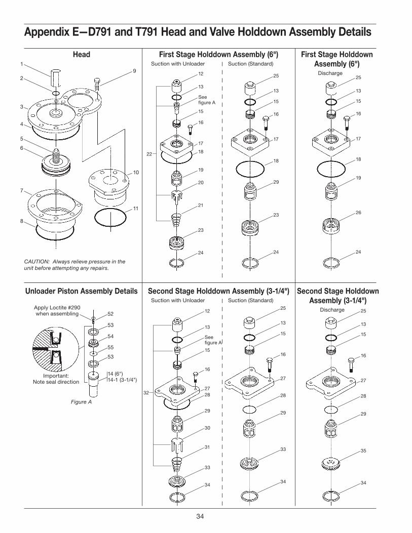
CAUTION: Always relieve pressure in the unit before attempting any repairs.
52
Important:Note seal direction
Apply Loctite #290when assembling
53
54
55
53
14 (6")14-1 (3-1/4")
first stage holddown Assembly (6")
Discharge
first stage holddown Assembly (6") Suction with Unloader Suction (Standard)
second stage holddown Assembly (3-1/4")
Discharge
second stage holddown Assembly (3-1/4") Suction with Unloader Suction (Standard)
unloader piston Assembly details
Figure A
head
Appendix e—d791 and t791 head and valve holddown Assembly details
e. Assembly details
34
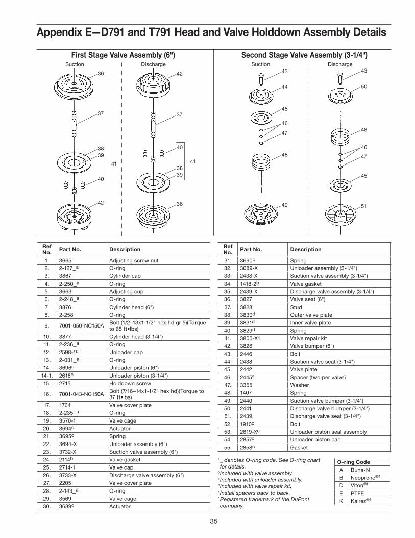
36
37
40
3839
42
41
42
37
40
3839
36
41
49
48
47
46
45
44
43
37
51
48
47
46
45
50
43
O-ring CodeA Buna-NB Neoprene®f
D Viton®f
E PTFEK Kalrez®f
ref no. part no. description
1. 3665 Adjusting screw nut2. 2-127 a O-ring3. 3867 Cylinder cap4. 2-250 a O-ring5. 3663 Adjusting cup6. 2-248 a O-ring7. 3876 Cylinder head (6")8. 2-258 O-ring
9. 7001-050-NC150A Bolt (1/2–13x1-1/2" hex hd gr 5)(Torque to 65 ft•lbs)
10. 3877 Cylinder head (3-1/4")11. 2-236 a O-ring12. 2598-1c Unloader cap13. 2-031 a O-ring14. 3696c Unloader piston (6")
14-1. 2618c Unloader piston (3-1/4")15. 2715 Holddown screw
16. 7001-043-NC150A Bolt (7/16–14x1-1/2" hex hd)(Torque to 37 ft•lbs)
17. 1764 Valve cover plate18. 2-235 a O-ring19. 3570-1 Valve cage20. 3694c Actuator21. 3695c Spring22. 3694-X Unloader assembly (6")23. 3732-X Suction valve assembly (6")24. 2114b Valve gasket25. 2714-1 Valve cap26. 3733-X Discharge valve assembly (6")27. 2205 Valve cover plate28. 2-143 a O-ring29. 3569 Valve cage30. 3689c Actuator
ref no. part no. description
31. 3690c Spring32. 3689-X Unloader assembly (3-1/4")33. 2438-X Suction valve assembly (3-1/4")34. 1418-2b Valve gasket35. 2439-X Discharge valve assembly (3-1/4")36. 3827 Valve seat (6")37. 3828 Stud38. 3830d Outer valve plate39. 3831d Inner valve plate40. 3829d Spring41. 3805-X1 Valve repair kit42. 3826 Valve bumper (6")43. 2446 Bolt44. 2438 Suction valve seat (3-1/4")45. 2442 Valve plate46. 2445e Spacer (two per valve)47. 3355 Washer48. 1407 Spring49. 2440 Suction valve bumper (3-1/4")50. 2441 Discharge valve bumper (3-1/4")51. 2439 Discharge valve seat (3-1/4")52. 1910c Bolt53. 2619-Xc Unloader piston seal assembly54. 2857c Unloader piston cap55. 2858c Gasket
a _ denotes O-ring code. See O-ring chart for details.
b Included with valve assembly.c Included with unloader assembly.d Included with valve repair kit.e Install spacers back to back.f Registered trademark of the DuPont company.
first stage valve Assembly (6") Suction Discharge
second stage valve Assembly (3-1/4") Suction Discharge
Appendix e—d791 and t791 head and valve holddown Assembly details
35
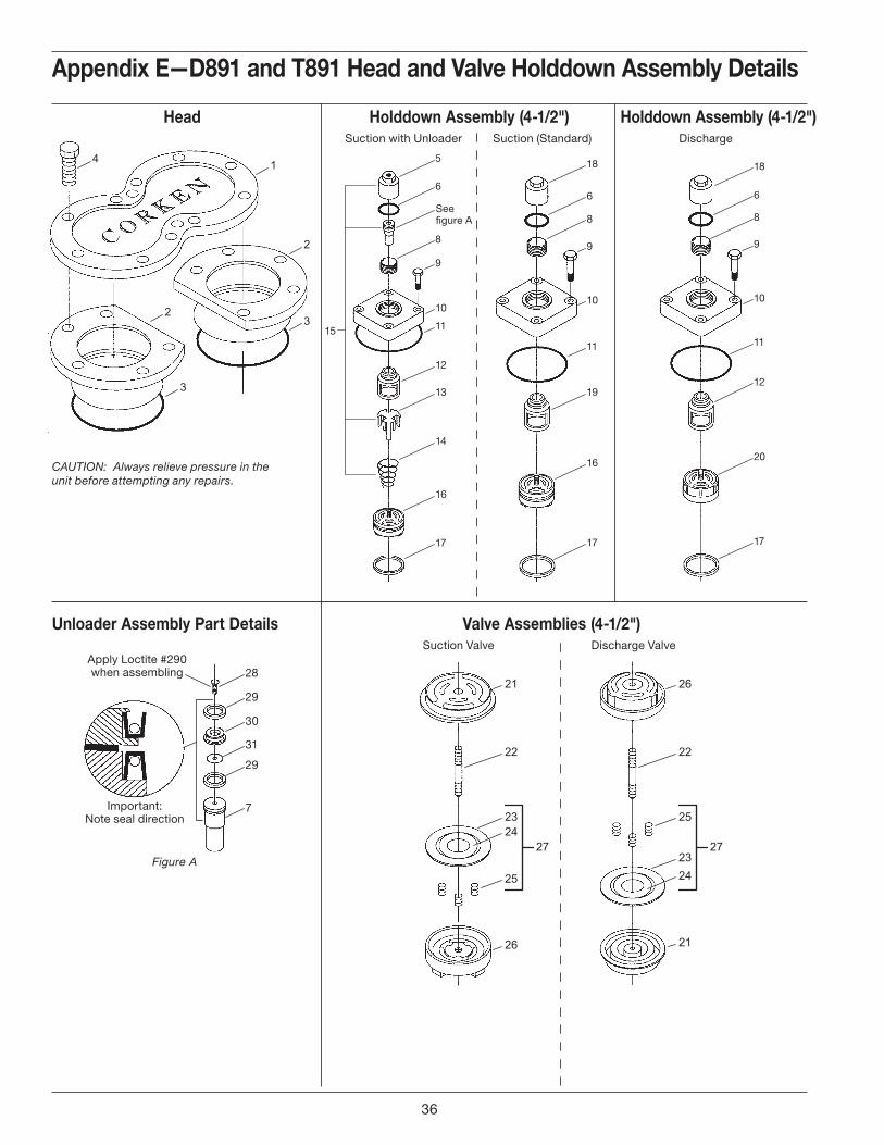
1
2
32
3
4
28
Important:Note seal direction
Apply Loctite #290when assembling
29
30
31
29
7
5
15
6
See�gure A
8
9
12
11
13
14
16
17
12
10
18
6
8
9
10
11
19
16
17
10
18
6
8
9
11
12
20
17
21
22
2324
25
26
27
26
22
2324
25
21
27
Appendix e—d891 and t891 head and valve holddown Assembly details
head holddown Assembly (4-1/2") Suction with Unloader Suction (Standard)
CAUTION: Always relieve pressure in the unit before attempting any repairs.
valve Assemblies (4-1/2") Suction Valve Discharge Valve
unloader Assembly part details
Figure A
holddown Assembly (4-1/2") Discharge
36
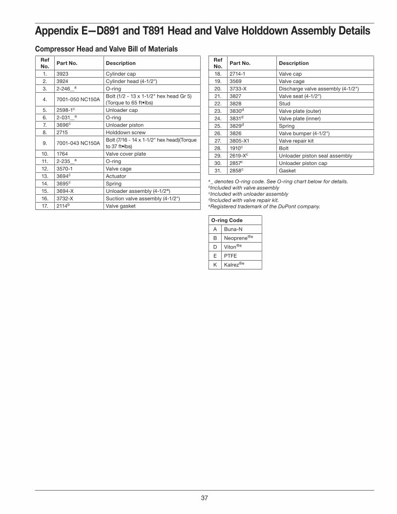
Appendix e—d891 and t891 head and valve holddown Assembly detailsCompressor head and valve bill of materials
ref no.
part no. description
1. 3923 Cylinder cap2. 3924 Cylinder head (4-1/2")3. 2-246 a O-ring
4. 7001-050 NC150ABolt (1/2 - 13 x 1-1/2" hex head Gr 5) (Torque to 65 ft•lbs)
5. 2598-1c Unloader cap6. 2-031 a O-ring7. 3696c Unloader piston8. 2715 Holddown screw
9. 7001-043 NC150ABolt (7/16 - 14 x 1-1/2" hex head)(Torque to 37 ft•lbs)
10. 1764 Valve cover plate11. 2-235 a O-ring12. 3570-1 Valve cage13. 3694c Actuator14. 3695c Spring15. 3694-X Unloader assembly (4-1/2")16. 3732-X Suction valve assembly (4-1/2")17. 2114b Valve gasket
a _ denotes O-ring code. See O-ring chart below for details.b Included with valve assemblyc Included with unloader assemblyd Included with valve repair kit.e Registered trademark of the DuPont company.
ref no.
part no. description
18. 2714-1 Valve cap19. 3569 Valve cage20. 3733-X Discharge valve assembly (4-1/2")21. 3827 Valve seat (4-1/2")22. 3828 Stud23. 3830d Valve plate (outer)24. 3831d Valve plate (inner)25. 3829d Spring26. 3826 Valve bumper (4-1/2")27. 3805-X1 Valve repair kit28. 1910c Bolt29. 2619-Xc Unloader piston seal assembly30. 2857c Unloader piston cap31. 2858c Gasket
O-ring Code
A Buna-N
B Neoprene®e
D Viton®e
E PTFE
K Kalrez®e
37
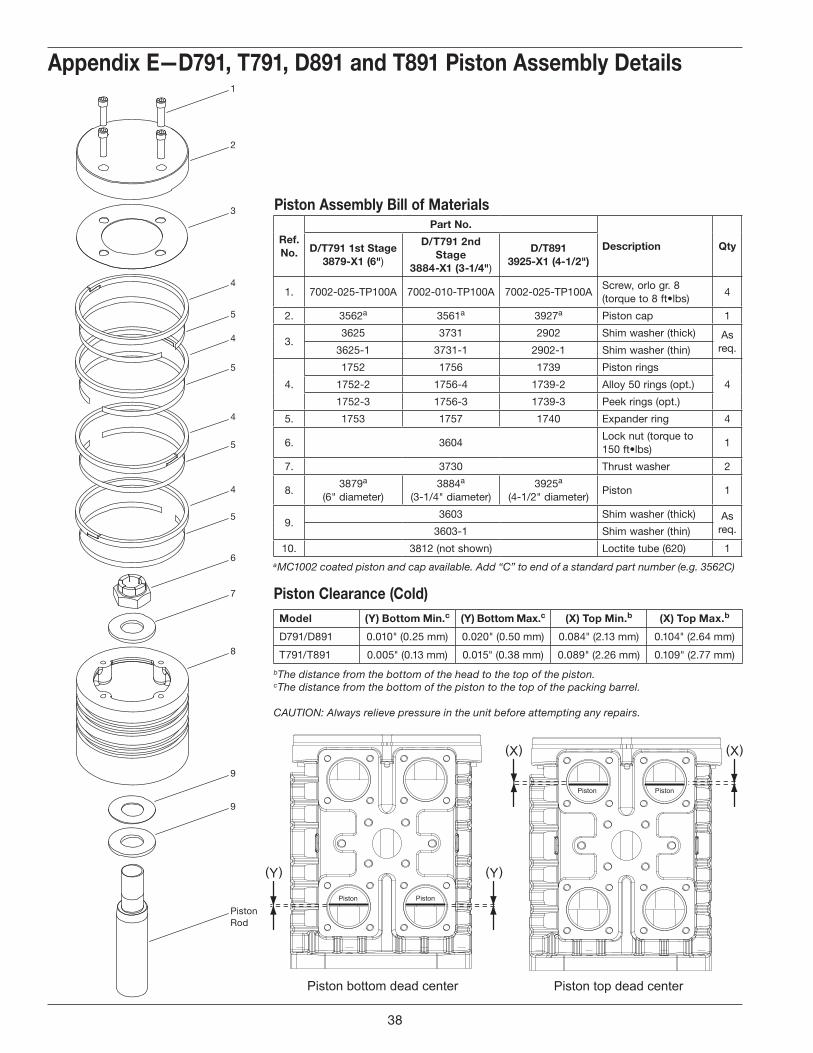
1
2
3
4
5
4
5
4
5
4
5
6
7
8
9
PistonRod
9
Piston bottom dead center
Piston Piston
(Y) (Y)
Piston top dead center
Piston Piston
(X) (X)
piston Assembly bill of materials
Appendix e—d791, t791, d891 and t891 piston Assembly details
ref. no.
part no.
description Qtyd/t791 1st stage 3879-x1 (6")
d/t791 2nd stage
3884-x1 (3-1/4")
d/t891 3925-x1 (4-1/2")
1. 7002-025-TP100A 7002-010-TP100A 7002-025-TP100AScrew, orlo gr. 8 (torque to 8 ft•lbs)
4
2. 3562a 3561a 3927a Piston cap 1
3.3625 3731 2902 Shim washer (thick) As
req.3625-1 3731-1 2902-1 Shim washer (thin)
4.
1752 1756 1739 Piston rings
41752-2 1756-4 1739-2 Alloy 50 rings (opt.)
1752-3 1756-3 1739-3 Peek rings (opt.)
5. 1753 1757 1740 Expander ring 4
6. 3604Lock nut (torque to 150 ft•lbs)
1
7. 3730 Thrust washer 2
8.3879a
(6" diameter)3884a
(3-1/4" diameter)3925a
(4-1/2" diameter)Piston 1
9.3603 Shim washer (thick) As
req.3603-1 Shim washer (thin)
10. 3812 (not shown) Loctite tube (620) 1
model (Y) bottom min.c (Y) bottom max.c (x) top min.b (x) top max.b
D791/D891 0.010" (0.25 mm) 0.020" (0.50 mm) 0.084" (2.13 mm) 0.104" (2.64 mm)
T791/T891 0.005" (0.13 mm) 0.015" (0.38 mm) 0.089" (2.26 mm) 0.109" (2.77 mm)
piston Clearance (Cold)
b The distance from the bottom of the head to the top of the piston.c The distance from the bottom of the piston to the top of the packing barrel.
CAUTION: Always relieve pressure in the unit before attempting any repairs.
a MC1002 coated piston and cap available. Add “C” to end of a standard part number (e.g. 3562C)
38
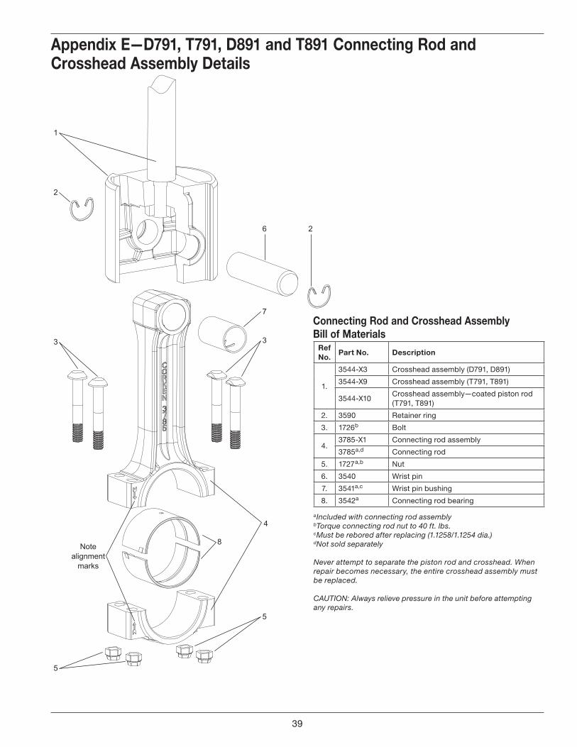
1
2
3
7
6
3
8
5
4
Notealignment
marks
5
2
Appendix E—D791, T791, D891 and T891 Connecting Rod and Crosshead Assembly Details
Ref No.
Part No. Description
1.
3544-X3 Crosshead assembly (D791, D891)
3544-X9 Crosshead assembly (T791, T891)
3544-X10Crosshead assembly—coated piston rod (T791, T891)
2. 3590 Retainer ring
3. 1726b Bolt
4.3785-X1 Connecting rod assembly
3785a,d Connecting rod
5. 1727a,b Nut
6. 3540 Wrist pin
7. 3541a,c Wrist pin bushing
8. 3542a Connecting rod bearing
Connecting Rod and Crosshead Assembly Bill of Materials
a Included with connecting rod assemblyb Torque connecting rod nut to 40 ft. lbs. c Must be rebored after replacing (1.1258/1.1254 dia.)d Not sold separately
Never attempt to separate the piston rod and crosshead. When repair becomes necessary, the entire crosshead assembly must be replaced.
CAUTION: Always relieve pressure in the unit before attempting any repairs.
39
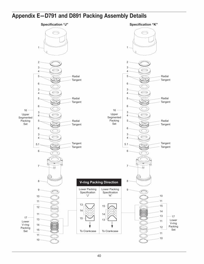
1
2
34
5
6
34
5
6
34
5
6
34
5.1
6
7
8
10
11
12
11
13
14
15
11
10
17
16
V-ring Packing Direction
Lower PackingSpecification
“J”
Lower PackingSpecification
“K”
13
14
15
15
14
13
To Crankcase To Crankcase
10
11
12
11
13
14
15
11
10
17
RadialTangent
RadialTangent
RadialTangent
TangentTangent
UpperSegmented
PackingSet
LowerV-ring
PackingSet
LowerV-ring
PackingSet
1
2
34
5
6
34
5
6
34
5
6
34
5.1
6
7
8
16
RadialTangent
RadialTangent
RadialTangent
TangentTangent
UpperSegmented
PackingSet
9 9
Appendix e—d791 and d891 packing Assembly detailsspecification “k”specification “J”
40
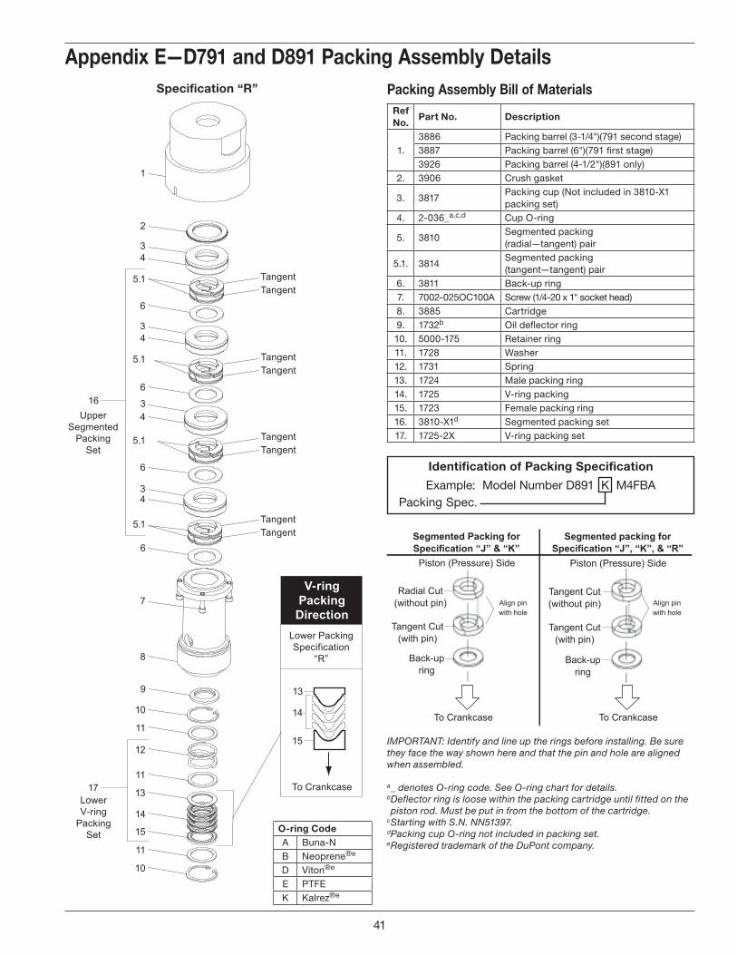
V-ringPackingDirection
Lower PackingSpecification
“R”
13
14
15
To Crankcase
16Upper
SegmentedPacking
Set
5.1
1
2
34
6
34
6
34
6
34
5.1
6
9
7
8
5.1
5.1 TangentTangent
TangentTangent
TangentTangent
TangentTangent
10
11
12
11
13
14
15
11
10
17LowerV-ring
PackingSet
packing Assembly bill of materialsref no.
part no. description
1.3886 Packing barrel (3-1/4")(791 second stage)3887 Packing barrel (6")(791 first stage)3926 Packing barrel (4-1/2")(891 only)
2. 3906 Crush gasket
3. 3817Packing cup (Not included in 3810-X1 packing set)
4. 2-036_a,c,d Cup O-ring
5. 3810Segmented packing (radial—tangent) pair
5.1. 3814Segmented packing (tangent—tangent) pair
6. 3811 Back-up ring7. 7002-025OC100A Screw (1/4-20 x 1" socket head)8. 3885 Cartridge9. 1732b Oil deflector ring10. 5000-175 Retainer ring11. 1728 Washer12. 1731 Spring13. 1724 Male packing ring14. 1725 V-ring packing15. 1723 Female packing ring16. 3810-X1d Segmented packing set17. 1725-2X V-ring packing set
identification of packing specification
Example: Model Number D891 K M4FBA Packing Spec.
IMPORTANT: Identify and line up the rings before installing. Be sure they face the way shown here and that the pin and hole are aligned when assembled.
a _ denotes O-ring code. See O-ring chart for details.b Deflector ring is loose within the packing cartridge until fitted on the piston rod. Must be put in from the bottom of the cartridge.
c Starting with S.N. NN51397. d Packing cup O-ring not included in packing set.e Registered trademark of the DuPont company.
Appendix e—d791 and d891 packing Assembly details
To Crankcase
Piston (Pressure) Side
Radial Cut(without pin)
Segmented Packing forSpecification “J” & “K”
Tangent Cut(with pin)
Back-upring
To Crankcase
Piston (Pressure) Side
Tangent Cut(without pin)
Segmented packing forSpecification “J”, “K”, & “R”
Tangent Cut(with pin)
Back-upring
Align pinwith hole
Align pinwith hole
specification “r”
O-ring CodeA Buna-NB Neoprene®e
D Viton®e
E PTFEK Kalrez®e
41
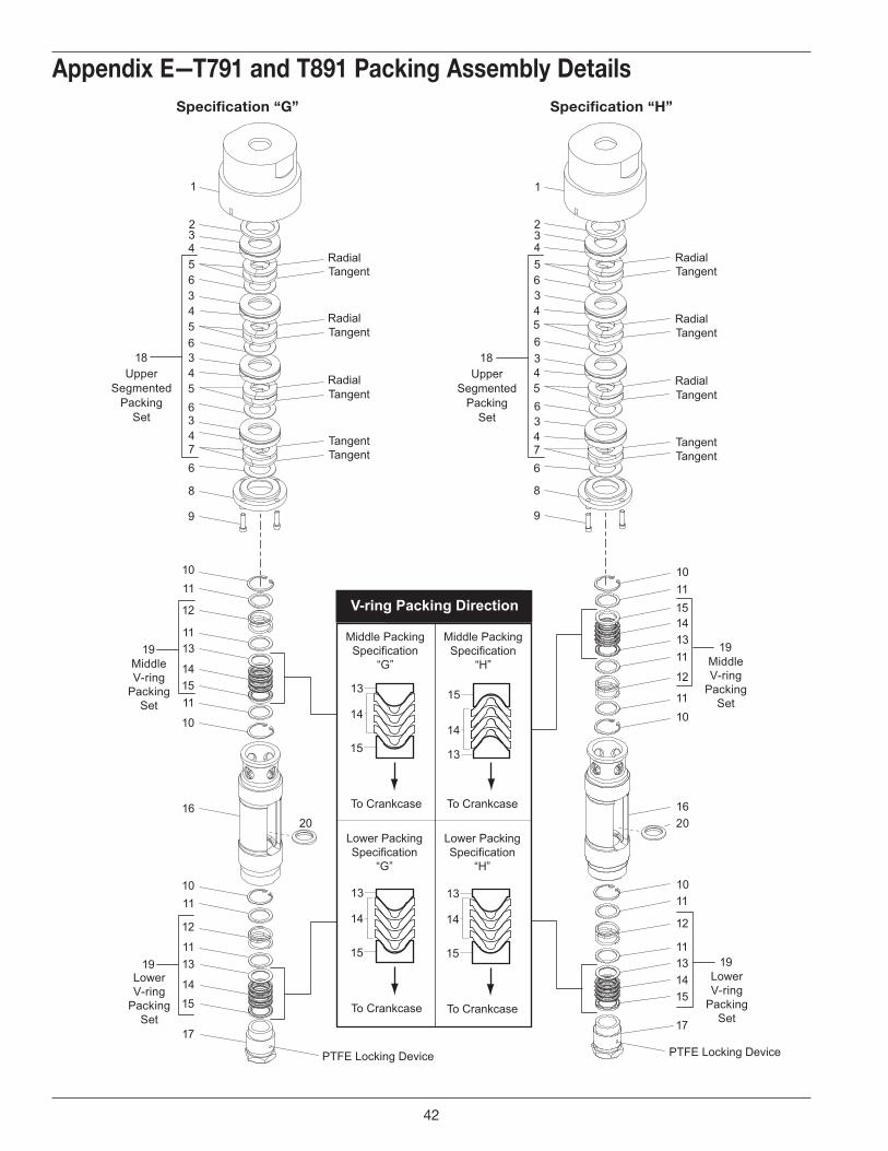
V-ring Packing Direction
Middle PackingSpecification
“G”
Middle PackingSpecification
“H”
13
14
15
15
14
13
To Crankcase To Crankcase
13
14
15
To Crankcase
13
14
15
To Crankcase
Lower PackingSpecification
“G”
Lower PackingSpecification
“H”
RadialTangent
RadialTangent
RadialTangent
TangentTangent
UpperSegmented
PackingSet
11
14
12
15
1620
11
17
11
12
1
2
3
8
18
9
10
13
14
19
15
13
4
56
5
34
5
6
6
76
34
11
10
10
11
LowerV-ring
PackingSet
19MiddleV-ring
PackingSet
UpperSegmented
PackingSet
11
11
15
12
16
14
17
11
12
1
2
3
8
18
9
10
13
1419
15
13
4
56
5
34
5
6
6
76
34
1110
10
11
LowerV-ring
PackingSet
19MiddleV-ring
PackingSet
RadialTangent
RadialTangent
RadialTangent
TangentTangent
34
34
20
PTFE Locking Device PTFE Locking Device
Appendix e—t791 and t891 packing Assembly detailsspecification “h”specification “g”
42
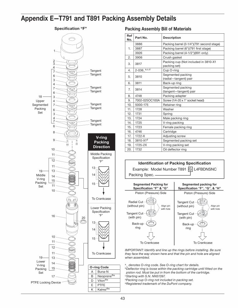
V-ringPackingDirection
Middle PackingSpecification
“F”
13
14
15
To Crankcase
13
14
15
To Crankcase
Lower PackingSpecification
“F”
TangentTangent
TangentTangent
TangentTangent
TangentTangent
UpperSegmented
PackingSet
11
14
12
15
16
11
17
11
12
1
2
3
8
18
9
10
13
14
19
15
13
4
76
7
34
7
6
6
76
34
1110
10
11
LowerV-ring
PackingSet
19MiddleV-ring
PackingSet
PTFE Locking Device
34
20
Appendix e—t791 and t891 packing Assembly detailspacking Assembly bill of materials
ref no.
part no. description
1.3886 Packing barrel (3-1/4")(791 second stage)3887 Packing barrel (6")(791 first stage)3926 Packing barrel (4-1/2")(891 only)
2. 3906 Crush gasket
3. 3817Packing cup (Not included in 3810-X1 packing set)
4. 2-036_a,c,d Cup O-ring
5. 3810Segmented packing (radial—tangent) pair
6. 3811 Back-up ring
7. 3814Segmented packing (tangent—tangent) pair
8. 4748 Packing adapter9. 7002-025OC100A Screw (1/4-20 x 1" socket head)10. 5000-175 Retainer ring11. 1728 Washer12. 1731 Spring13. 1724 Male packing ring14. 1725 V-ring packing15. 1723 Female packing ring16. 4746 Cartridge17. 1722-X Adjusting screw18. 3810-X1d Segmented packing set19. 1725-2X V-ring packing set20. 1732 Oil deflector ring
identification of packing specification
Example: Model Number T891 G L4FBDNSNC Packing Spec.
IMPORTANT: Identify and line up the rings before installing. Be sure they face the way shown here and that the pin and hole are aligned when assembled.
a _ denotes O-ring code. See O-ring chart for details.b Deflector ring is loose within the packing cartridge until fitted on the piston rod. Must be put in from the bottom of the cartridge.
c Starting with S.N. NN51397. d Packing cup O-ring not included in packing set.e Registered trademark of the DuPont company.
To Crankcase
Piston (Pressure) Side
Radial Cut(without pin)
Segmented Packing forSpecification “F” & “G”
Tangent Cut(with pin)
Back-upring
To Crankcase
Piston (Pressure) Side
Tangent Cut(without pin)
Segmented packing forSpecification “F”, “G”, & “H”
Tangent Cut(with pin)
Back-upring
Align pinwith hole
Align pinwith hole
specification “f”
O-ring CodeA Buna-NB Neoprene®e
D Viton®e
E PTFEK Kalrez®e
43
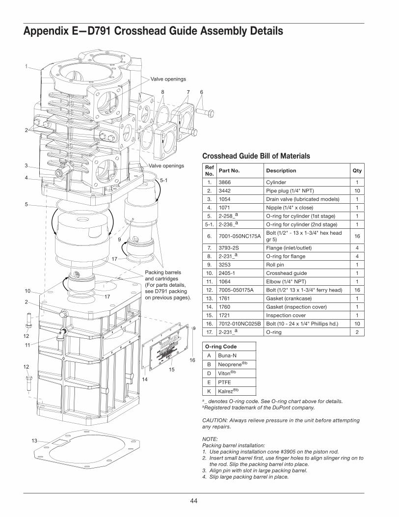
17
17
12
12
13
14
15
16
Packing barrels and cartridges(For parts details, see D791 packing on previous pages).
ref no.
part no. description Qty
1. 3866 Cylinder 1
2. 3442 Pipe plug (1/4" NPT) 10
3. 1054 Drain valve (lubricated models) 1
4. 1071 Nipple (1/4" x close) 1
5. 2-258_a O-ring for cylinder (1st stage) 1
5-1. 2-236_a O-ring for cylinder (2nd stage) 1
6. 7001-050NC175ABolt (1/2" - 13 x 1-3/4" hex head gr 5)
16
7. 3793-2S Flange (inlet/outlet) 4
8. 2-231_a O-ring for flange 4
9. 3253 Roll pin 1
10. 2405-1 Crosshead guide 1
11. 1064 Elbow (1/4" NPT) 1
12. 7005-050175A Bolt (1/2" 13 x 1-3/4" ferry head) 16
13. 1761 Gasket (crankcase) 1
14. 1760 Gasket (inspection cover) 1
15. 1721 Inspection cover 1
16. 7012-010NC025B Bolt (10 - 24 x 1/4" Phillips hd.) 10
17. 2-231_a O-ring 2
Crosshead guide bill of materials
Appendix e—d791 Crosshead guide Assembly details
a _ denotes O-ring code. See O-ring chart above for details.b Registered trademark of the DuPont company.
CAUTION: Always relieve pressure in the unit before attempting any repairs.
NOTE: Packing barrel installation: 1. Use packing installation cone #3905 on the piston rod.2. Insert small barrel first, use finger holes to align slinger ring on to
the rod. Slip the packing barrel into place.3. Align pin with slot in large packing barrel.4. Slip large packing barrel in place.
O-ring Code
A Buna-N
B Neoprene®b
D Viton®b
E PTFE
K Kalrez®b
44
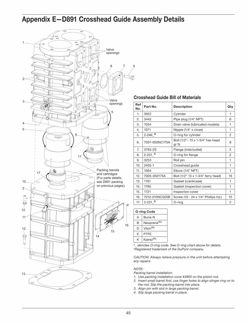
17
17
12
12
13
1415
16
Packing barrels and cartridges(For parts details, see D891 packing on previous pages).
O-ring Code
A Buna-N
B Neoprene®b
D Viton®b
E PTFE
K Kalrez®b
ref no.
part no. description Qty
1. 3922 Cylinder 1
2. 3442 Pipe plug (1/4" NPT) 6
3. 1054 Drain valve (lubricated models) 1
4. 1071 Nipple (1/4" x close) 1
5. 2-246_a O-ring for cylinder 2
6. 7001-050NC175ABolt (1/2"- 13 x 1-3/4" hex head gr 5)
8
7. 3793-2S Flange (inlet/outlet) 2
8. 2-231_a O-ring for flange 2
9. 3253 Roll pin 1
10. 2405-1 Crosshead guide 1
11. 1064 Elbow (1/4" NPT) 1
12. 7005-050175A Bolt (1/2" 13 x 1-3/4" ferry head) 16
13. 1761 Gasket (crankcase) 1
14. 1760 Gasket (inspection cover) 1
15. 1721 Inspection cover 1
16. 7012-010NC025B Screw (10 - 24 x 1/4" Phillips hd.) 10
17. 2-231_a O-ring 2
Crosshead guide bill of materials
Appendix e—d891 Crosshead guide Assembly details
a _ denotes O-ring code. See O-ring chart above for details.b Registered trademark of the DuPont company.
CAUTION: Always relieve pressure in the unit before attempting any repairs.
NOTE: Packing barrel installation: 1. Use packing installation cone #3905 on the piston rod.2. Insert small barrel first, use finger holes to align slinger ring on to
the rod. Slip the packing barrel into place.3. Align pin with slot in large packing barrel.4. Slip large packing barrel in place.
45
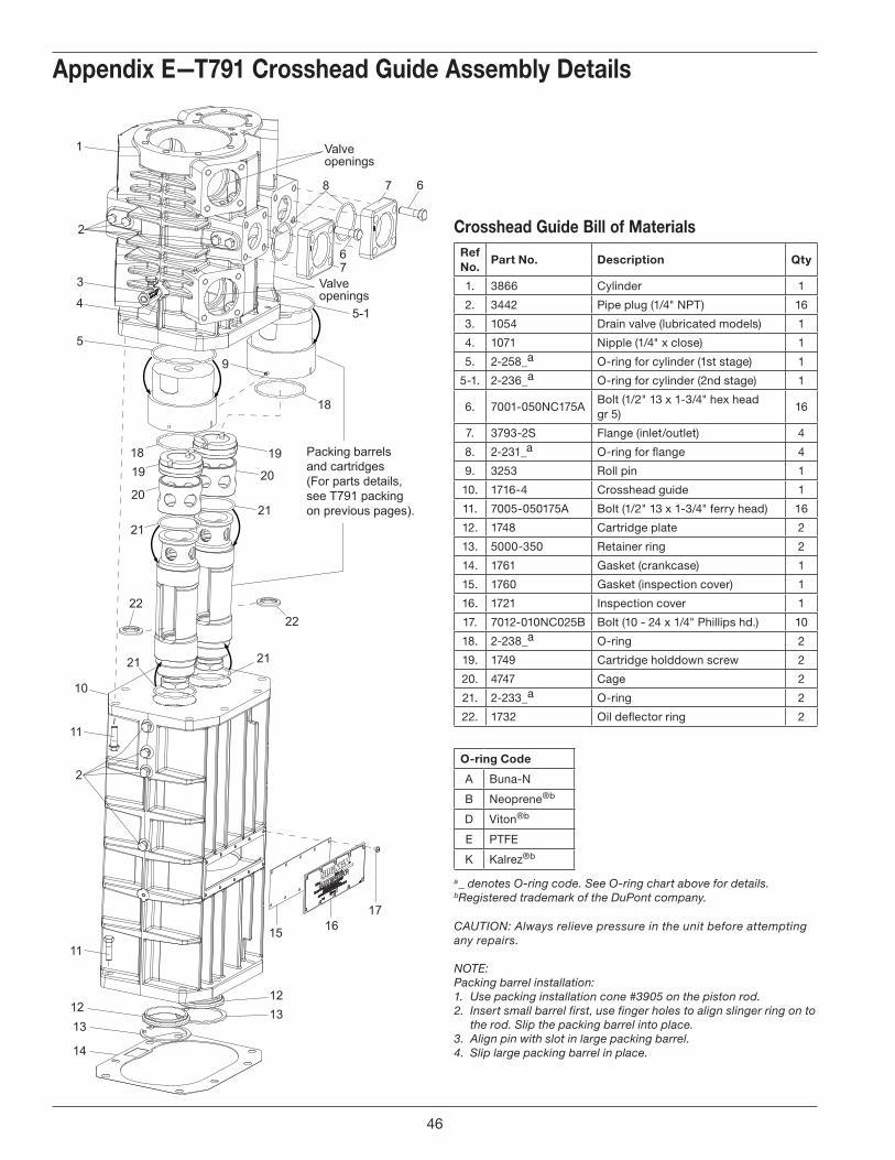
18
5-1
1819
19
2020
21
11
11
1213
14
1312
15 1617
21
21 21
2222
Packing barrels and cartridges(For parts details, see T791 packing on previous pages).
ref no.
part no. description Qty
1. 3866 Cylinder 1
2. 3442 Pipe plug (1/4" NPT) 16
3. 1054 Drain valve (lubricated models) 1
4. 1071 Nipple (1/4" x close) 1
5. 2-258_a O-ring for cylinder (1st stage) 1
5-1. 2-236_a O-ring for cylinder (2nd stage) 1
6. 7001-050NC175ABolt (1/2" 13 x 1-3/4" hex head gr 5)
16
7. 3793-2S Flange (inlet/outlet) 4
8. 2-231_a O-ring for flange 4
9. 3253 Roll pin 1
10. 1716-4 Crosshead guide 1
11. 7005-050175A Bolt (1/2" 13 x 1-3/4" ferry head) 16
12. 1748 Cartridge plate 2
13. 5000-350 Retainer ring 2
14. 1761 Gasket (crankcase) 1
15. 1760 Gasket (inspection cover) 1
16. 1721 Inspection cover 1
17. 7012-010NC025B Bolt (10 - 24 x 1/4" Phillips hd.) 10
18. 2-238_a O-ring 2
19. 1749 Cartridge holddown screw 2
20. 4747 Cage 2
21. 2-233_a O-ring 2
22. 1732 Oil deflector ring 2
Crosshead guide bill of materials
Appendix e—t791 Crosshead guide Assembly details
a _ denotes O-ring code. See O-ring chart above for details.b Registered trademark of the DuPont company.
CAUTION: Always relieve pressure in the unit before attempting any repairs.
NOTE: Packing barrel installation: 1. Use packing installation cone #3905 on the piston rod.2. Insert small barrel first, use finger holes to align slinger ring on to
the rod. Slip the packing barrel into place.3. Align pin with slot in large packing barrel.4. Slip large packing barrel in place.
O-ring Code
A Buna-N
B Neoprene®b
D Viton®b
E PTFE
K Kalrez®b
46
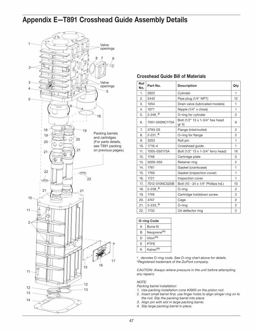
18
1819
19
2020
21
11
2
11
1213
14
21
21 21
22
22
1312
15 1617
Packing barrels and cartridges(For parts details, see T891 packing on previous pages).
ref no.
part no. description Qty
1. 3922 Cylinder 1
2. 3442 Pipe plug (1/4" NPT) 12
3. 1054 Drain valve (lubricated models) 1
4. 1071 Nipple (1/4" x close) 1
5. 2-246_a O-ring for cylinder 2
6. 7001-050NC175ABolt (1/2" 13 x 1-3/4" hex head gr 5)
6
7. 3793-2S Flange (inlet/outlet) 2
8. 2-231_a O-ring for flange 2
9. 3253 Roll pin 1
10. 1716-4 Crosshead guide 1
11. 7005-050175A Bolt (1/2" 13 x 1-3/4" ferry head) 16
12. 1748 Cartridge plate 2
13. 5000-350 Retainer ring 2
14. 1761 Gasket (crankcase) 1
15. 1760 Gasket (inspection cover) 1
16. 1721 Inspection cover 1
17. 7012-010NC025B Bolt (10 - 24 x 1/4" Phillips hd.) 10
18. 2-238_a O-ring 2
19. 1749 Cartridge holddown screw 2
20. 4747 Cage 2
21. 2-233_a O-ring 2
22. 1732 Oil deflector ring 2
Crosshead guide bill of materials
Appendix e—t891 Crosshead guide Assembly details
a _ denotes O-ring code. See O-ring chart above for details.b Registered trademark of the DuPont company.
CAUTION: Always relieve pressure in the unit before attempting any repairs.
NOTE: Packing barrel installation: 1. Use packing installation cone #3905 on the piston rod.2. Insert small barrel first, use finger holes to align slinger ring on to
the rod. Slip the packing barrel into place.3. Align pin with slot in large packing barrel.4. Slip large packing barrel in place.
O-ring Code
A Buna-N
B Neoprene®b
D Viton®b
E PTFE
K Kalrez®b
47
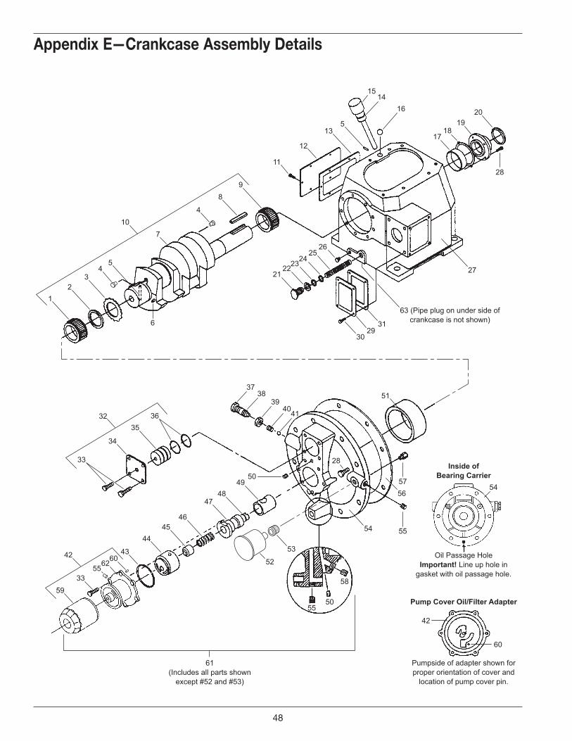
12
34
5
6
710
4
30
54
2931
52
53
27
63 (Pipe plug on under side ofcrankcase is not shown)
8
21
17
16
3738
394140
15
54
14
1819
20
22232425
26
9
11
12
135
33
34
35
43
4445
46
4748
42
51
4956
50
3632
59
5533
606242
28
55
61(Includes all parts shown
except #52 and #53)
50
58
Inside ofBearing Carrier
Pump Cover Oil/Filter Adapter
Oil Passage HoleImportant! Line up hole in
gasket with oil passage hole.
Pumpside of adapter shown forproper orientation of cover and
location of pump cover pin.
57
55
60
28
Appendix e—Crankcase Assembly details
48
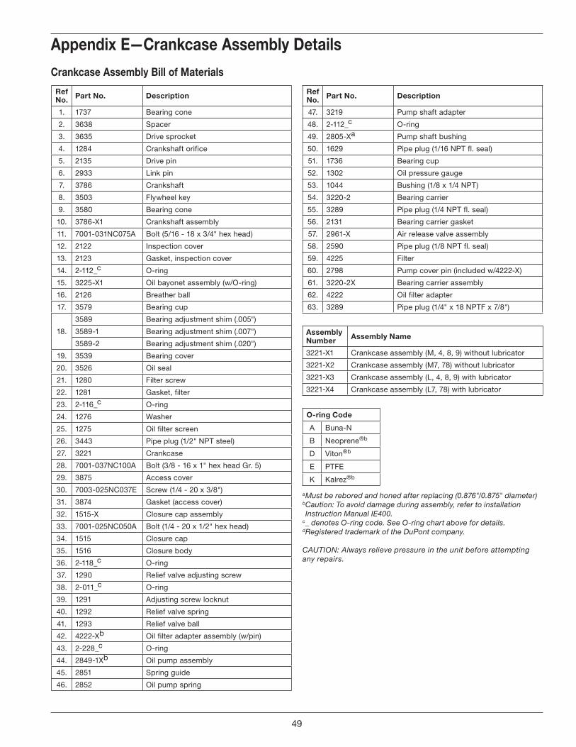
Appendix e—Crankcase Assembly details
ref no. part no. description
1. 1737 Bearing cone
2. 3638 Spacer
3. 3635 Drive sprocket
4. 1284 Crankshaft orifice
5. 2135 Drive pin
6. 2933 Link pin
7. 3786 Crankshaft
8. 3503 Flywheel key
9. 3580 Bearing cone
10. 3786-X1 Crankshaft assembly
11. 7001-031NC075A Bolt (5/16 - 18 x 3/4" hex head)
12. 2122 Inspection cover
13. 2123 Gasket, inspection cover
14. 2-112_c O-ring
15. 3225-X1 Oil bayonet assembly (w/O-ring)
16. 2126 Breather ball
17. 3579 Bearing cup
18.
3589 Bearing adjustment shim (.005")
3589-1 Bearing adjustment shim (.007")
3589-2 Bearing adjustment shim (.020")
19. 3539 Bearing cover
20. 3526 Oil seal
21. 1280 Filter screw
22. 1281 Gasket, filter
23. 2-116_c O-ring
24. 1276 Washer
25. 1275 Oil filter screen
26. 3443 Pipe plug (1/2" NPT steel)
27. 3221 Crankcase
28. 7001-037NC100A Bolt (3/8 - 16 x 1" hex head Gr. 5)
29. 3875 Access cover
30. 7003-025NC037E Screw (1/4 - 20 x 3/8")
31. 3874 Gasket (access cover)
32. 1515-X Closure cap assembly
33. 7001-025NC050A Bolt (1/4 - 20 x 1/2" hex head)
34. 1515 Closure cap
35. 1516 Closure body
36. 2-118_c O-ring
37. 1290 Relief valve adjusting screw
38. 2-011_c O-ring
39. 1291 Adjusting screw locknut
40. 1292 Relief valve spring
41. 1293 Relief valve ball
42. 4222-Xb Oil filter adapter assembly (w/pin)
43. 2-228_c O-ring
44. 2849-1Xb Oil pump assembly
45. 2851 Spring guide
46. 2852 Oil pump spring
Crankcase Assembly bill of materials
Assembly number Assembly name
3221-X1 Crankcase assembly (M, 4, 8, 9) without lubricator
3221-X2 Crankcase assembly (M7, 78) without lubricator
3221-X3 Crankcase assembly (L, 4, 8, 9) with lubricator
3221-X4 Crankcase assembly (L7, 78) with lubricator
a Must be rebored and honed after replacing (0.876"/0.875" diameter)b Caution: To avoid damage during assembly, refer to installation Instruction Manual IE400.
c _ denotes O-ring code. See O-ring chart above for details.d Registered trademark of the DuPont company. CAUTION: Always relieve pressure in the unit before attempting any repairs.
ref no. part no. description
47. 3219 Pump shaft adapter
48. 2-112_c O-ring
49. 2805-Xa Pump shaft bushing
50. 1629 Pipe plug (1/16 NPT fl. seal)
51. 1736 Bearing cup
52. 1302 Oil pressure gauge
53. 1044 Bushing (1/8 x 1/4 NPT)
54. 3220-2 Bearing carrier
55. 3289 Pipe plug (1/4 NPT fl. seal)
56. 2131 Bearing carrier gasket
57. 2961-X Air release valve assembly
58. 2590 Pipe plug (1/8 NPT fl. seal)
59. 4225 Filter
60. 2798 Pump cover pin (included w/4222-X)
61. 3220-2X Bearing carrier assembly
62. 4222 Oil filter adapter
63. 3289 Pipe plug (1/4" x 18 NPTF x 7/8")
O-ring Code
A Buna-N
B Neoprene®b
D Viton®b
E PTFE
K Kalrez®b
49
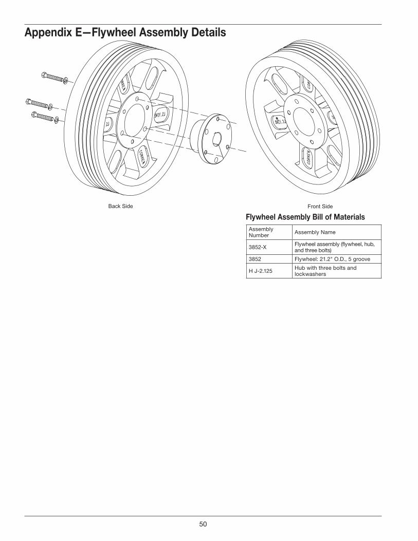
Back Side Front Side
Assembly Number Assembly Name
3852-X Flywheel assembly (flywheel, hub, and three bolts)
3852 Flywheel: 21.2" O.D., 5 groove
H J-2.125 Hub with three bolts and lockwashers
flywheel Assembly bill of materials
Appendix e—flywheel Assembly details
50

51
Printed in the U.S.A.April 2011
Corken, Inc. • A Unit of IDEX Corporation
3805 N.W. 36th St., Oklahoma City, OK 73112
Phone (405) 946-5576 • Fax (405) 948-7343
Visit our website at http://www.corken.com
or e-mail us at [email protected]