Embed Size (px)
Citation preview

i
UNIVERSITY OF NAIROBI
PROJECT TITLE: IMPLEMENTING VPN TO ACCESS PRIVATE LAN/WAN USING
GPRS NETWORK
PROJECT INDEX: PRJ 106
NAME: MWIHAKI HOSEA NDUNG’U
REG. NUMBER: F17/1984/2004
SUPERVISOR: DR. MAURICE K. MANG’OLI
EXAMINER: DR. M. MBUTHIA
Project report submitted in partial fulfilment of the requirement for the award of the degree of
Bachelor of Science in Electrical and Electronic Engineering of the University of Nairobi
20th
May, 2009
Department of Electrical and Information Engineering

ii
DEDICATION
This document is especially dedicated to Colonel HE Vialou Clark, Hugh Dayton and their
families in England for their unremitting support throughout my education. To you all I remain
grateful.

iii
AKNOWLEDGEMENTS
I take this opportunity to express my heartily gratitude and thanks to my project supervisor Dr.
Maurice K Mang’oli for his valuable advice and support without which this document would not
have come into existence.
Special thanks to Mr. Tenai and Mr. Joram of ICT Chiromo for their continued assistance and
permission to use the university network in implementing my project.
My sincere thanks to Mr. Musau and Dr. Wekesa of Electrical Engineering Department,
University of Nairobi for their intellectual counsel and support.
I wish to place on record my appreciation and give credit to my classmate Reagan Mbitiru,
Antony G. Nyagathu, Magdalene Wambui and others for their kind words and great
encouragement. It was great to have you as my classmates.
Words seems not enough to express my earnest gratitude to my mother Serah Mwihaki and my
siblings for their love, keen interest, encouragement, moral support and kind prayers through out
this work.
iv
ABSTRACT
The growth of the Internet and the success of mobile networks imply that the subsequent
development will be an increasing demand for mobile access to Internet applications. It is
therefore increasingly important that mobile radio networks support these applications in an
efficient manner.
An end-to-end Virtual Private Network (VPN) deployment over GSM/GPRS mobile network
was presented and analyzed in this document. With known public IP address that served as the
interface for secure connection between public network that the client was on and the private
corporate LAN, the remote client was able access the private network from wherever location as
long as there was GPRS network coverage and that the client had the authentication rights to
access the private corporate LAN.
The VPN deployment discussed in this document was based on SSL/TLS protocol suite which
overwhelms the defects of the tradition VPN. One of the best, and certainly the least inexpensive,
is the open source SSL VPN, OpenVPN. IPSec remote access VPN was briefly discussed in
chapter two and latter abandoned. IPSec VPN is dense and contains too many options to be
configured and administered securely by non expert personnel. However, OpenVPN rejects these
complexities of IPSec by use of SSL/TLS protocol.
OpenVPN provided authentication and encryption by use of Public Key Security Infrastructure
(PKI), digital certificates and Certificate Authority (CA) before any connection between the
remote clients and the OpenVPN server was completed. This was done by using client and server
certificates and keys. This was also described in this document.
Finally a qualitative evaluation of the proposed VPN scheme and the outline of an alternative
approach for future work were presented.
v
LIST OF ABBREVIATIONS
VPN Virtual Private Network
GSM Global Service for Mobile Communication
GPRS General Packet for Radio Services
EDGE Enhanced Data for GSM Evolution
3G Third Generations
LAN Local Area Network
WAN Wide Area network
SSL Secure Socket Layer
TLS Transport Layer Security
PKI Public Key Infrastructure
TCP Transport Control Protocol
UDP Universal Data Protocol
NAT Network Address Traversal
DHCP Dynamic Host Configuration protocol
IPSec IP Security
CA Certificate Authority
GTP GPRS Tunnelling Protocol
IP Internet Protocol
IEFT Internet Engineering Task Force
MPLS Multi-Packet Label Switching
ATM Asynchronous Transfer Mode
GRE Generic Routing Encryption
SLA Service Level Agreement
RADIUS Remote Authentication Dial-In User Service
AH Authentication Header
ESP Encapsulating Security Payload
IKE Internet Key Exchange
SPI Security Parameter Index
SADB Security Association Database
DES Data Encryption Standard
vi
MS Mobile Station
PDP Packet Data Protocol
SGSN Serving GPRS Support Node
GGSN Gateway GPRS Support Node
SG Security Gateway
SA Security Association
ISAKMP Internet Security Association for Key Management Protocol
DH Diffie-Hellman
MD Message Digest
SHA Standard Hashing Algorithm
AES Advanced Encryption Standard
HMAC Hash Message Authentication Code
RSA Rivest-Shamir-Adleman
MAC Message Authentication Code
DNS Domain Name System
VOIP Voice Over IP
DMZ De-Militarized Zones
APN Access Point Name
DN Distinguished Name
CRL Certificate Revoking List
vii
Table of Contents
DEDICATION ................................................................................................................................. i
AKNOWLEDGEMENTS.............................................................................................................. iii
ABSTRACT ................................................................................................................................... iv
LIST OF ABBREVIATIONS ......................................................................................................... v
Table of Contents .......................................................................................................................... vii
CHAPTER ONE: INTRODUCTION ............................................................................................. 1
1.1 PROJECT AIM ................................................................................................................. 1
1.2 OBJECTIVES ................................................................................................................... 1
1.3 METHODOLOGY ............................................................................................................ 1
1.3.1 Network architecture design ....................................................................................... 1
1.3.2 Security architecture design........................................................................................ 1
1.4 PROBLEM SCOPE .......................................................................................................... 2
1.5 APPROACH ..................................................................................................................... 3
CHAPTER TWO: TECHNICAL BACKGROUND ...................................................................... 4
2.0 Definition .............................................................................................................................. 4
2.1.0 VPN Security Architecture Design. ............................................................................... 4
2.1.1 IPSec VPN...................................................................................................................... 5
2.1.2 IPSec Security Protocols ................................................................................................ 6
2.1.3 IPSec Transport Mode .................................................................................................... 6
2.1.4 Encapsulating Security Header (ESP) ............................................................................ 7
2.1.5 Authentication Header (AH) .......................................................................................... 8
2.2.0 VPN Services in GPRS ...................................................................................................... 9
2.2.1 Network architecture design......................................................................................... 10
2.3.0 SSL/TLS Protocol Description ....................................................................................... 12
viii
2.3.1 How SSL/TLS works ................................................................................................... 13
2.3.2 NAT Traversal.............................................................................................................. 13
2.4.0 OpenVPN Security........................................................................................................... 14
2.4.1 Key Generation ............................................................................................................ 14
2.4.2 Key Derivation/Exchange ............................................................................................ 14
2.4.3 TLS Handshake in Detail ............................................................................................. 14
2.4.3.1 Phase 1. Establishing Security Capabilities ........................................................... 14
2.4.3.2 Phase 2. Server Authentication and key Exchange. .............................................. 16
2.4.3.3 Phase 3. Client Authentication and Key Exchange: .............................................. 16
2.5 .0 Hashing Message Authentication Code HMAC/Hashing................................................. 17
2.6.0 TLS Record Protocol ....................................................................................................... 17
2.6.1 ChangeCipherSpec Protocol ........................................................................................ 19
2.6.2 Alert protocol ............................................................................................................... 19
2.7.0 Security ........................................................................................................................... 19
2.8.0 OpenVPN Applications ................................................................................................... 20
2.9.0 Client/Server Remote Access Vulnerabilities and Threats .............................................. 21
2.9.1 Remote Client Security ................................................................................................ 21
2.10.0 ......................................................................... Access Point Name (APN) on GPRS networks
....................................................................................................................................................... 21
CHAPTER THREE: DESIGN AND METHODOLOGY ............................................................ 24
3.0.0 VPN For WAN/LAN Design ........................................................................................... 24
3.1.0 Equipment Used; .............................................................................................................. 25
3.2.0 OpenVPN Software. ........................................................................................................ 25
3.2.1 Installation of Open VPN. ............................................................................................ 25
3.3.2 OpenVPN Security........................................................................................................... 25
3.3.1 Client/Server Remote Access Vulnerabilities and Threats .......................................... 26
ix
3.3.1.1 Remote Client Security .......................................................................................... 26
3.3.2 Generating the master Certificate Authority (CA) certificate and key ........................ 28
3.3.3 Generating certificate and key for server ..................................................................... 29
3.3.4 Generating Certificate and Key for Several Clients ..................................................... 29
3.3.5 Generating Diffie-Hellman Parameters ........................................................................ 30
3.3.6 Creating Server Configuration file. .............................................................................. 30
3.3.7 Creating Client(s) Configuration Files ......................................................................... 30
3.3.8 Summary of the Key Files ............................................................................................ 30
3.4.1 Configuring the Router................................................................................................. 31
3.4.2 Configuring Windows XP Server ................................................................................ 32
3.4.3 Starting up the VPN and Testing for Initial Connectivity ............................................ 32
3.4.4 Trouble Shooting .......................................................................................................... 33
3.5.0 Including multiple machines on the server side when using a routed VPN (dev tun) ..... 33
3.6.0 Including multiple machines on the client side ............................................................ 34
3.7.0 Implementing a load-balancing/ failover configuration .................................................. 36
3.7.1 Client ............................................................................................................................ 36
3.7.2 Server ............................................................................................................................ 36
CHAPTER FOUR: RESULTS AND ANALYSIS ....................................................................... 37
4.1.0 Results and Analysis. .................................................................................................. 37
4.2.0 Accessing remote network ............................................................................................... 39
4.3.0 VPN Evaluation............................................................................................................ 41
4.3.0 What Distinguishes OpenVPN from other VPN Packages .......................................... 42
CHAPTER FIVE: CONCLUSION AND FURTHER WORK .................................................... 43

x
5.1.0 CONCLUSION ............................................................................................................ 43
5.2.0 RECOMMENDATION FOR FURTHER WORK ...................................................... 43
REFERENCES; ............................................................................................................................ 44
APPENDIX A ............................................................................................................................... 46
A1 Client Configuration File ................................................................................................ 46
A2 Server Configuration File Settings .................................................................................. 47
A3 How Certificates and Keys were generated .................................................................... 50
1
CHAPTER ONE: INTRODUCTION
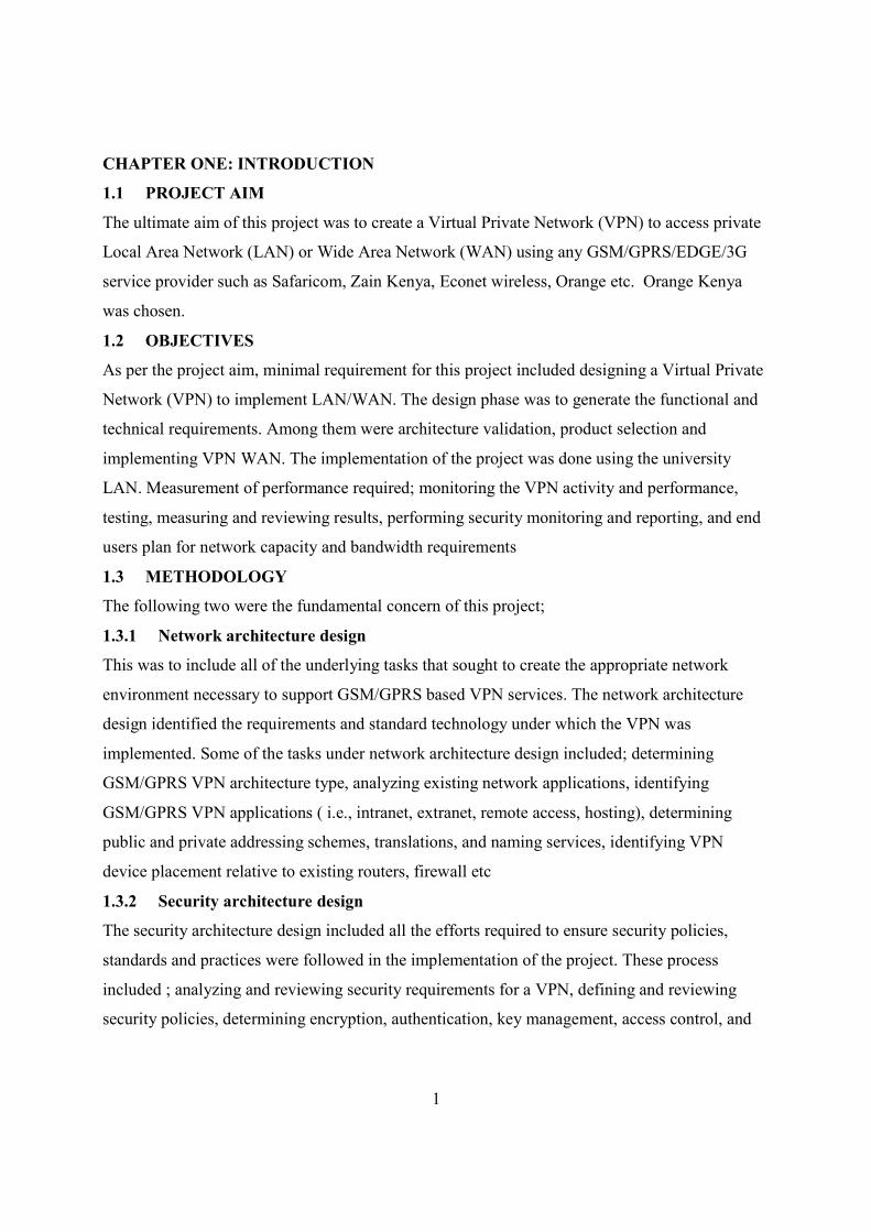
1.1 PROJECT AIM
The ultimate aim of this project was to create a Virtual Private Network (VPN) to access private
Local Area Network (LAN) or Wide Area Network (WAN) using any GSM/GPRS/EDGE/3G
service provider such as Safaricom, Zain Kenya, Econet wireless, Orange etc. Orange Kenya
was chosen.
1.2 OBJECTIVES
As per the project aim, minimal requirement for this project included designing a Virtual Private
Network (VPN) to implement LAN/WAN. The design phase was to generate the functional and
technical requirements. Among them were architecture validation, product selection and
implementing VPN WAN. The implementation of the project was done using the university
LAN. Measurement of performance required; monitoring the VPN activity and performance,
testing, measuring and reviewing results, performing security monitoring and reporting, and end
users plan for network capacity and bandwidth requirements
1.3 METHODOLOGY
The following two were the fundamental concern of this project;
1.3.1 Network architecture design
This was to include all of the underlying tasks that sought to create the appropriate network
environment necessary to support GSM/GPRS based VPN services. The network architecture
design identified the requirements and standard technology under which the VPN was
implemented. Some of the tasks under network architecture design included; determining
GSM/GPRS VPN architecture type, analyzing existing network applications, identifying
GSM/GPRS VPN applications ( i.e., intranet, extranet, remote access, hosting), determining
public and private addressing schemes, translations, and naming services, identifying VPN
device placement relative to existing routers, firewall etc
1.3.2 Security architecture design
The security architecture design included all the efforts required to ensure security policies,
standards and practices were followed in the implementation of the project. These process
included ; analyzing and reviewing security requirements for a VPN, defining and reviewing
security policies, determining encryption, authentication, key management, access control, and
2
filtering policies, determining user authentication and public key Infrastructure (KPI)
requirements in the project implementation.
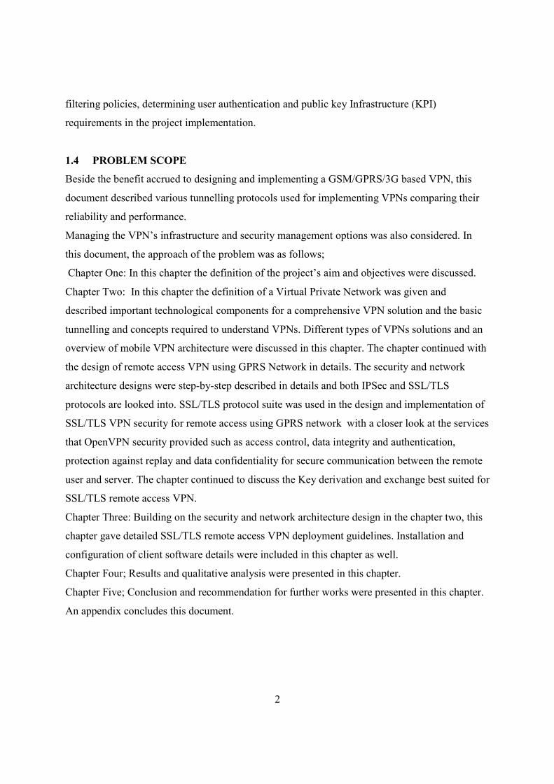
1.4 PROBLEM SCOPE
Beside the benefit accrued to designing and implementing a GSM/GPRS/3G based VPN, this
document described various tunnelling protocols used for implementing VPNs comparing their
reliability and performance.
Managing the VPN’s infrastructure and security management options was also considered. In
this document, the approach of the problem was as follows;
Chapter One: In this chapter the definition of the project’s aim and objectives were discussed.
Chapter Two: In this chapter the definition of a Virtual Private Network was given and
described important technological components for a comprehensive VPN solution and the basic
tunnelling and concepts required to understand VPNs. Different types of VPNs solutions and an
overview of mobile VPN architecture were discussed in this chapter. The chapter continued with
the design of remote access VPN using GPRS Network in details. The security and network
architecture designs were step-by-step described in details and both IPSec and SSL/TLS
protocols are looked into. SSL/TLS protocol suite was used in the design and implementation of
SSL/TLS VPN security for remote access using GPRS network with a closer look at the services
that OpenVPN security provided such as access control, data integrity and authentication,
protection against replay and data confidentiality for secure communication between the remote
user and server. The chapter continued to discuss the Key derivation and exchange best suited for
SSL/TLS remote access VPN.
Chapter Three: Building on the security and network architecture design in the chapter two, this
chapter gave detailed SSL/TLS remote access VPN deployment guidelines. Installation and
configuration of client software details were included in this chapter as well.
Chapter Four; Results and qualitative analysis were presented in this chapter.
Chapter Five; Conclusion and recommendation for further works were presented in this chapter.
An appendix concludes this document.
3
1.5 APPROACH
Considering that most of today’s VPN services are based on IP and the use of the Internet have
gained public interest and market acceptance, VPNs are evolving from voice to data services and
from wire-line to wireless data networks. Like traditional VPNs, IP VPNs utilize shared facilities
to emulate private networks and deliver reliable, secure services to end users.
While IP VPNs uses IP tunnelling technologies, for this project GPRS Tunnelling Protocol
(GTP) technologies for GSM/GPRS VPN was used for the dynamic mobile tunnel and IEFT-
defined tunnelling protocols on the fixed side of the private network.
4
CHAPTER TWO: TECHNICAL BACKGROUND
2.0 Definition
Virtual private networks (VPNs) can be defined as a private communications network often used
within a company, or by several companies or organizations, to communicate confidentially over
a publicly accessible network infrastructure. VPN message traffic can be carried over a public
networking infrastructure (e.g. the Internet) on top of standard protocols, or over a service
provider’s private network with a defined Service Level Agreement (SLA) between the VPN
customer and the VPN service provider. With VPNs there two types of security issues—
encryption and encapsulation. VPNs provide the following functions;
a. Extend geographic connectivity.
b. Improve security where data lines have not been ciphered.
c. Reduce operational costs versus traditional WAN.
d. Reduce transit time and transportation costs for remote users.
e. Simplify network topology in certain scenarios.
f. Provide global networking opportunities.
2.1.0 VPN Security Architecture Design.
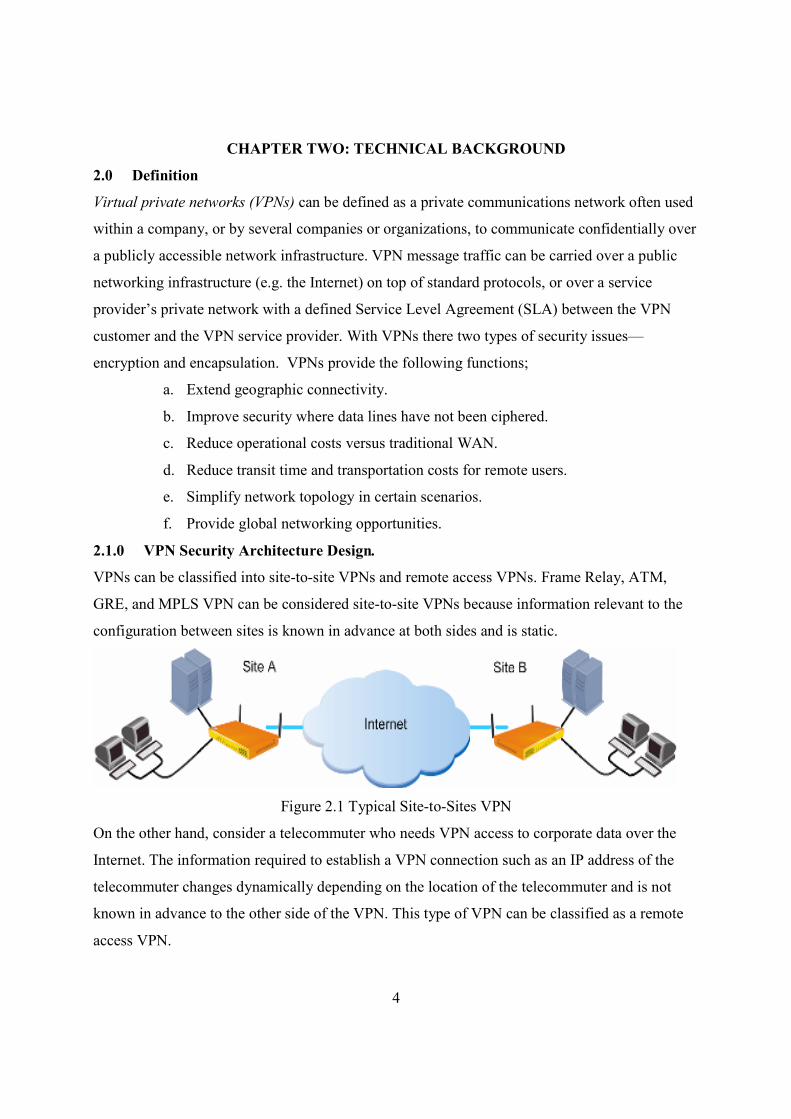
VPNs can be classified into site-to-site VPNs and remote access VPNs. Frame Relay, ATM,
GRE, and MPLS VPN can be considered site-to-site VPNs because information relevant to the
configuration between sites is known in advance at both sides and is static.
Figure 2.1 Typical Site-to-Sites VPN
On the other hand, consider a telecommuter who needs VPN access to corporate data over the
Internet. The information required to establish a VPN connection such as an IP address of the
telecommuter changes dynamically depending on the location of the telecommuter and is not
known in advance to the other side of the VPN. This type of VPN can be classified as a remote
access VPN.
5
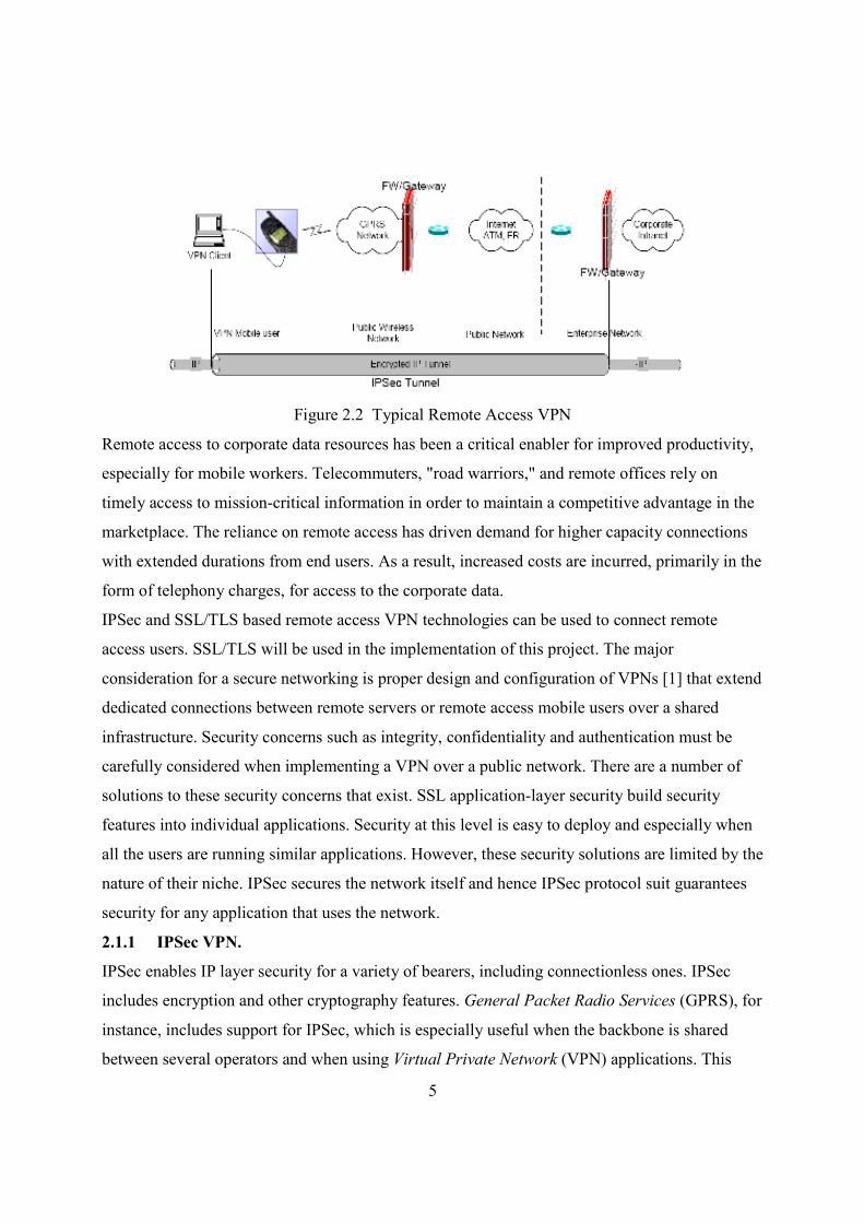
Figure 2.2 Typical Remote Access VPN
Remote access to corporate data resources has been a critical enabler for improved productivity,
especially for mobile workers. Telecommuters, "road warriors," and remote offices rely on
timely access to mission-critical information in order to maintain a competitive advantage in the
marketplace. The reliance on remote access has driven demand for higher capacity connections
with extended durations from end users. As a result, increased costs are incurred, primarily in the
form of telephony charges, for access to the corporate data.
IPSec and SSL/TLS based remote access VPN technologies can be used to connect remote
access users. SSL/TLS will be used in the implementation of this project. The major
consideration for a secure networking is proper design and configuration of VPNs [1] that extend
dedicated connections between remote servers or remote access mobile users over a shared
infrastructure. Security concerns such as integrity, confidentiality and authentication must be
carefully considered when implementing a VPN over a public network. There are a number of
solutions to these security concerns that exist. SSL application-layer security build security
features into individual applications. Security at this level is easy to deploy and especially when
all the users are running similar applications. However, these security solutions are limited by the
nature of their niche. IPSec secures the network itself and hence IPSec protocol suit guarantees
security for any application that uses the network.
2.1.1 IPSec VPN.
IPSec enables IP layer security for a variety of bearers, including connectionless ones. IPSec
includes encryption and other cryptography features. General Packet Radio Services (GPRS), for
instance, includes support for IPSec, which is especially useful when the backbone is shared
between several operators and when using Virtual Private Network (VPN) applications. This
6
functionality is one of the more obvious successful applications, where GPRS-enabled laptops
(via a PC card or a Bluetooth-enabled GPRS phone) are always connected to the corporate LAN
through either RADIUS server that authenticates the user and gives him or her access to
corporate resources or DHCP which is used for IP address assignment.
2.1.2 IPSec Security Protocols
The objective of IPSec is to provide security services for IP packets at the network layer of the
OSI model. These services include access control, data integrity, authentication, protection
against replay, and data confidentiality. Encapsulating security payload (ESP) [3] and
authentication header (AH) [2] are the two IPSec security protocols used to provide this security
for an IP datagram and which support transport and tunnel modes of use [4]. Here, transport
mode is discussed since one of the GPRS VPN termination is a MS or laptop which would tend
to be difficult to function in the tunnel mode as IP address is dynamic.
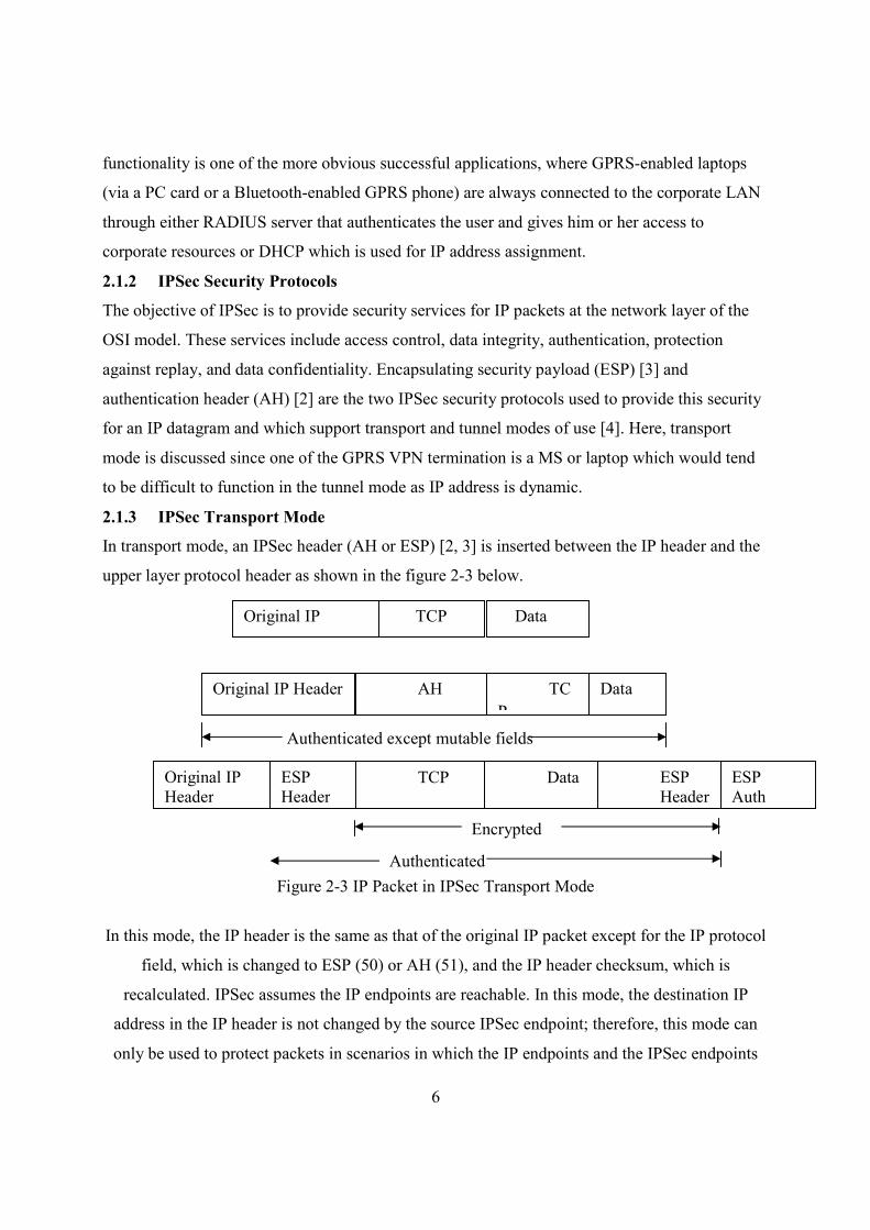
2.1.3 IPSec Transport Mode
In transport mode, an IPSec header (AH or ESP) [2, 3] is inserted between the IP header and the
upper layer protocol header as shown in the figure 2-3 below.
Figure 2-3 IP Packet in IPSec Transport Mode
In this mode, the IP header is the same as that of the original IP packet except for the IP protocol
field, which is changed to ESP (50) or AH (51), and the IP header checksum, which is
recalculated. IPSec assumes the IP endpoints are reachable. In this mode, the destination IP
address in the IP header is not changed by the source IPSec endpoint; therefore, this mode can
only be used to protect packets in scenarios in which the IP endpoints and the IPSec endpoints
Original IP
Header
ESP
Header
TCP Data ESP
Header
ESP
Auth
Original IP
header
TCP Data
Original IP Header AH TC
P
Data
Authenticated except mutable fields
Authenticated
Encrypted
7
are the same. From an IPSec VPN point of view, this mode is most useful when traffic between
two hosts must be protected, rather than when traffic moves from site-to-site, and each site has
many hosts. IPSec transport mode can still be used for VPN connectivity if Generic Route
Encapsulation (GRE) IP tunnels are used between the VPN gateways. The GRE tunnel endpoints
serve as "host" endpoints. IPSec protects the GRE tunnel traffic in transport mode.
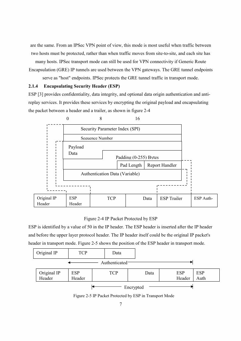
2.1.4 Encapsulating Security Header (ESP)
ESP [3] provides confidentiality, data integrity, and optional data origin authentication and anti-
replay services. It provides these services by encrypting the original payload and encapsulating
the packet between a header and a trailer, as shown in figure 2-4
Figure 2-4 IP Packet Protected by ESP
ESP is identified by a value of 50 in the IP header. The ESP header is inserted after the IP header
and before the upper layer protocol header. The IP header itself could be the original IP packet's
header in transport mode. Figure 2-5 shows the position of the ESP header in transport mode.
Original IP
Header
ESP
Header
TCP Data ESP Trailer ESP Auth-
Authentication Data (Variable)
Pad Length Report Handler
Padding (0-255) Bytes
Payload
Data
Sequence Number
Security Parameter Index (SPI)
0 8 16
Original IP
Header
ESP
Header TCP Data ESP
Header
ESP
Auth
Encrypted
Authenticated
Original IP
header
TCP Data
Figure 2-5 IP Packet Protected by ESP in Transport Mode
8
The security parameter index (SPI) in the ESP header is a 32-bit value that, combined with the
destination address and protocol in the preceding IP header, identifies the security association
(SA) to be used to process the packet. The SPI is an arbitrary number chosen by the destination
peer during Internet Key Exchange (IKE) [4] negotiation between the peers. It functions like an
index number that can be used to look up the SA in the security association database (SADB).
The sequence number is a unique monotonically increasing number inserted into the header by
the sender. Sequence numbers provide anti-replay protection. The data being encrypted by ESP
is in the payload data field. The algorithm used to encrypt the payload may require an
initialization vector (IV), which is also carried in the data payload. Note that the IV is
authenticated but not encrypted. If the encryption algorithm used is DES, then the first eight
bytes of the protected data field is the IV; 3DES and AES also have an 8-byte IV.
Padding in the ESP header is the addition of bits to the ESP header; the number of bits to be
padded depends on the encryption algorithm that is used. The Pad Length field indicates the
number of pad bytes added so that the original data can be restored on decryption. The next
header payload identifies the type of data in the payload. Authentication digest in the ESP header
is used to verify data integrity. Because authentication is always applied after encryption, a check
for validity of the data is done upon receipt of the packet and before decryption.
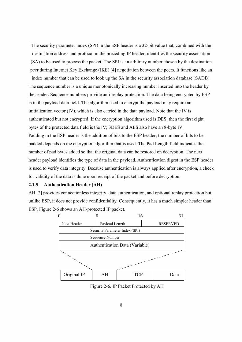
2.1.5 Authentication Header (AH)
AH [2] provides connectionless integrity, data authentication, and optional replay protection but,
unlike ESP, it does not provide confidentiality. Consequently, it has a much simpler header than
ESP. Figure 2-6 shows an AH-protected IP packet.
Security Parameter Index (SPI)
Original IP
Header
TCP Data AH
Authentication Data (Variable)
Sequence Number
Next Header Payload Length RESERVED
0 8 16 31
Figure 2-6. IP Packet Protected by AH
9
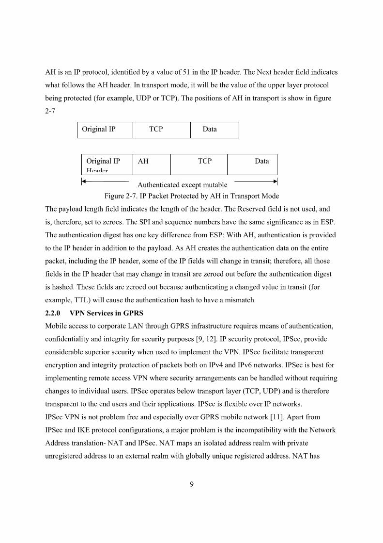
AH is an IP protocol, identified by a value of 51 in the IP header. The Next header field indicates
what follows the AH header. In transport mode, it will be the value of the upper layer protocol
being protected (for example, UDP or TCP). The positions of AH in transport is show in figure
2-7
Figure 2-7. IP Packet Protected by AH in Transport Mode
The payload length field indicates the length of the header. The Reserved field is not used, and
is, therefore, set to zeroes. The SPI and sequence numbers have the same significance as in ESP.
The authentication digest has one key difference from ESP: With AH, authentication is provided
to the IP header in addition to the payload. As AH creates the authentication data on the entire
packet, including the IP header, some of the IP fields will change in transit; therefore, all those
fields in the IP header that may change in transit are zeroed out before the authentication digest
is hashed. These fields are zeroed out because authenticating a changed value in transit (for
example, TTL) will cause the authentication hash to have a mismatch
2.2.0 VPN Services in GPRS
Mobile access to corporate LAN through GPRS infrastructure requires means of authentication,
confidentiality and integrity for security purposes [9, 12]. IP security protocol, IPSec, provide
considerable superior security when used to implement the VPN. IPSec facilitate transparent
encryption and integrity protection of packets both on IPv4 and IPv6 networks. IPSec is best for
implementing remote access VPN where security arrangements can be handled without requiring
changes to individual users. IPSec operates below transport layer (TCP, UDP) and is therefore
transparent to the end users and their applications. IPSec is flexible over IP networks.
IPSec VPN is not problem free and especially over GPRS mobile network [11]. Apart from
IPSec and IKE protocol configurations, a major problem is the incompatibility with the Network
Address translation- NAT and IPSec. NAT maps an isolated address realm with private
unregistered address to an external realm with globally unique registered address. NAT has
Original IP
header
TCP Data
Original IP
Header
AH TCP Data
Authenticated except mutable
10
limited use in IPSec VPN as IPSec views the packet processing of NAT as a violation of
integrity.
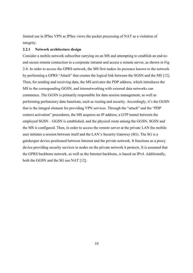
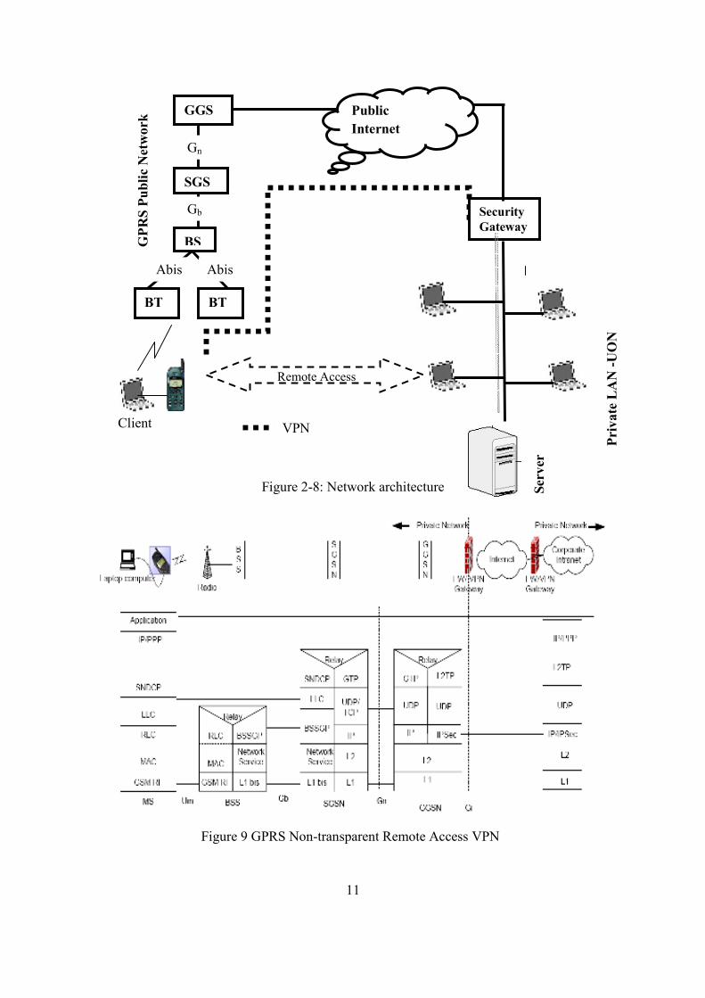
2.2.1 Network architecture design
Consider a mobile network subscriber carrying on an MS and attempting to establish an end-to-
end secure remote connection to a corporate intranet and access a remote server, as shown in Fig
2-8. In order to access the GPRS network, the MS first makes its presence known to the network
by performing a GPRS “Attach” that creates the logical link between the SGSN and the MS [12].
Then, for sending and receiving data, the MS activates the PDP address, which introduces the
MS to the corresponding GGSN, and internetworking with external data networks can
commence. The GGSN is primarily responsible for data session management, as well as
performing perfunctory data functions, such as routing and security. Accordingly, it’s the GGSN
that is the integral element for providing VPN services. Through the “attach” and the “PDP
context activation” procedures, the MS acquires an IP address, a GTP tunnel between the
employed SGSN – GGSN is established, and the physical route among the GGSN, SGSN and
the MS is configured. Then, in order to access the remote server at the private LAN the mobile
user initiates a session between itself and the LAN’s Security Gateway (SG). The SG is a
gatekeeper device positioned between Internet and the private network. It functions as a proxy
device providing security services to nodes on the private network it protects. It is assumed that
the GPRS backbone network, as well as the Internet backbone, is based on IPv4. Additionally,
both the GGSN and the SG use NAT [12].
11
Figure 2-8: Network architecture
Figure 9 GPRS Non-transparent Remote Access VPN
Ser
ver
VPN
GP
RS
Pu
bli
c N
etw
ork
Client
Pri
va
te L
AN
-U
ON
Remote Access
Security
Gateway
BS
SGS
GGS Public
Internet
BT BT
Abis Abis
Gb
Gn
SGS
12
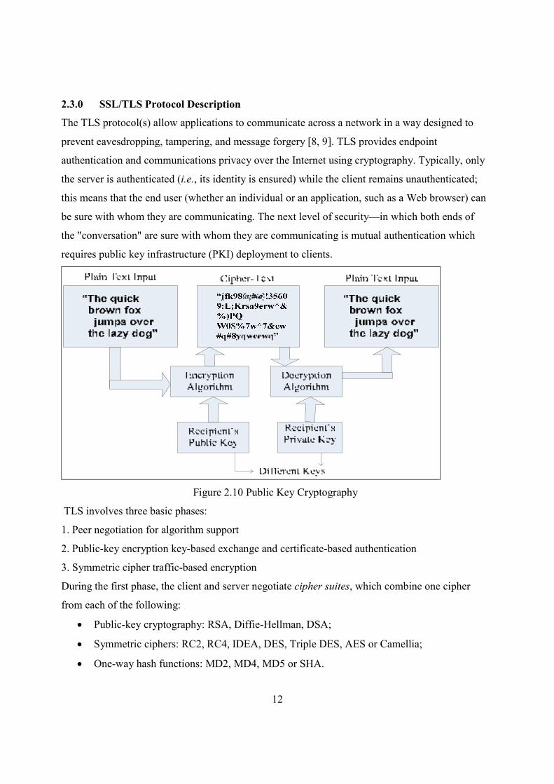
2.3.0 SSL/TLS Protocol Description
The TLS protocol(s) allow applications to communicate across a network in a way designed to
prevent eavesdropping, tampering, and message forgery [8, 9]. TLS provides endpoint
authentication and communications privacy over the Internet using cryptography. Typically, only
the server is authenticated (i.e., its identity is ensured) while the client remains unauthenticated;
this means that the end user (whether an individual or an application, such as a Web browser) can
be sure with whom they are communicating. The next level of security—in which both ends of
the "conversation" are sure with whom they are communicating is mutual authentication which
requires public key infrastructure (PKI) deployment to clients.
Figure 2.10 Public Key Cryptography
TLS involves three basic phases:
1. Peer negotiation for algorithm support
2. Public-key encryption key-based exchange and certificate-based authentication
3. Symmetric cipher traffic-based encryption
During the first phase, the client and server negotiate cipher suites, which combine one cipher
from each of the following:
• Public-key cryptography: RSA, Diffie-Hellman, DSA;
• Symmetric ciphers: RC2, RC4, IDEA, DES, Triple DES, AES or Camellia;
• One-way hash functions: MD2, MD4, MD5 or SHA.
13
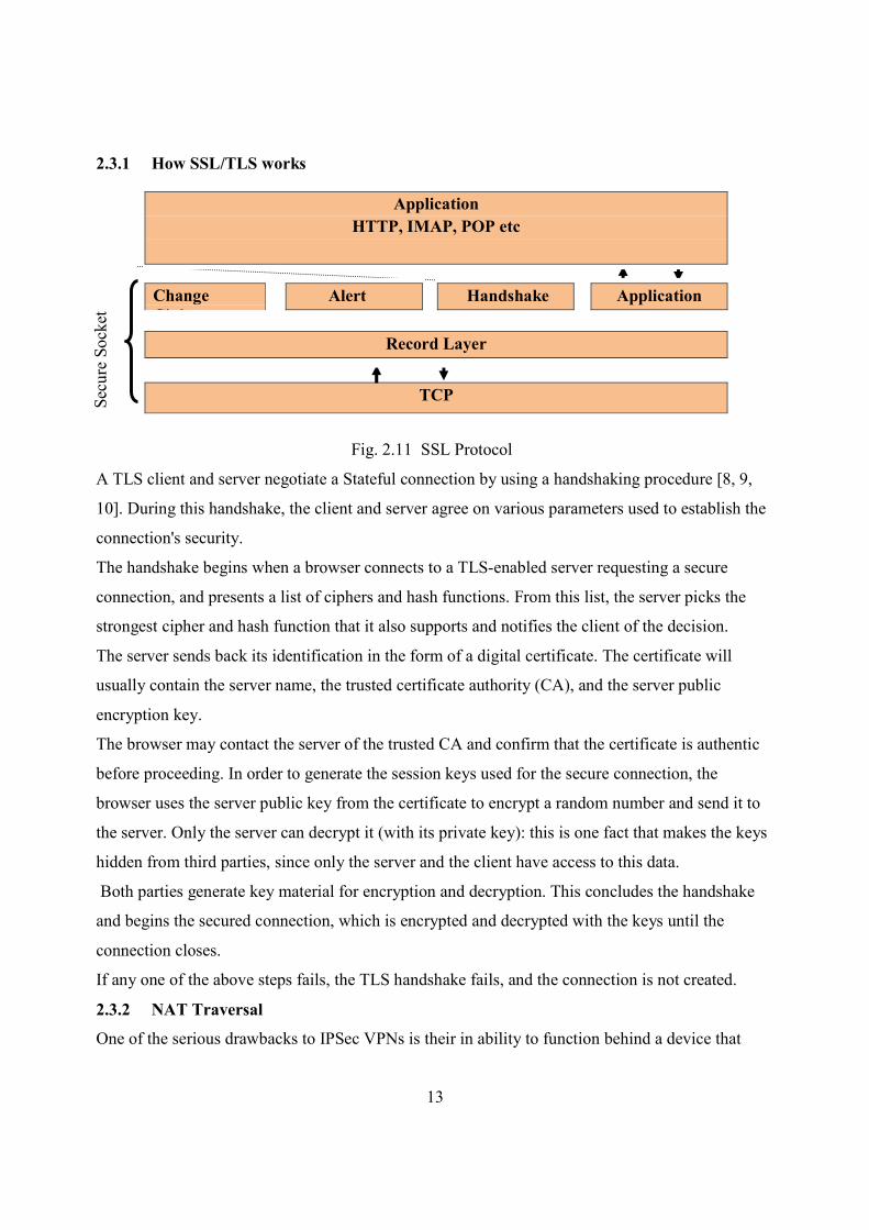
2.3.1 How SSL/TLS works
Fig. 2.11 SSL Protocol
A TLS client and server negotiate a Stateful connection by using a handshaking procedure [8, 9,
10]. During this handshake, the client and server agree on various parameters used to establish the
connection's security.
The handshake begins when a browser connects to a TLS-enabled server requesting a secure
connection, and presents a list of ciphers and hash functions. From this list, the server picks the
strongest cipher and hash function that it also supports and notifies the client of the decision.
The server sends back its identification in the form of a digital certificate. The certificate will
usually contain the server name, the trusted certificate authority (CA), and the server public
encryption key.
The browser may contact the server of the trusted CA and confirm that the certificate is authentic
before proceeding. In order to generate the session keys used for the secure connection, the
browser uses the server public key from the certificate to encrypt a random number and send it to
the server. Only the server can decrypt it (with its private key): this is one fact that makes the keys
hidden from third parties, since only the server and the client have access to this data.
Both parties generate key material for encryption and decryption. This concludes the handshake
and begins the secured connection, which is encrypted and decrypted with the keys until the
connection closes.
If any one of the above steps fails, the TLS handshake fails, and the connection is not created.
2.3.2 NAT Traversal
One of the serious drawbacks to IPSec VPNs is their in ability to function behind a device that
Application
HTTP, IMAP, POP etc
Change
Cipher
Alert Handshake Application
Record Layer
TCP Secure Socket
14
does NAT [11]. The Authentication Header (AH) mode in IPSec hashes the source address as part
of its authentication process. If NAT changes this source address, as it always does, the VPN on
the other end of the tunnel will get a different hash when it checks the packet integrity and drop
the packet thinking it has been tampered with. SSL/TLS does not run authentication on the packet
source address so it can successfully traverse a NAT device.
2.4.0 OpenVPN Security
OpenVPN is built on a solid security foundation.
2.4.1 Key Generation
Once the SSL/TLS handshake has authenticated both ends, it will generate four different keys; an
HMAC send key, an HMAC receive key, an encrypt/decrypt send key and encrypt/decrypt
receive key [6].
2.4.2 Key Derivation/Exchange
SSL/TLS OpenVPN uses the standard RSA/DH Exchange handshake with client authentication to
accomplish key exchange [10, 15].
2.4.3 TLS Handshake in Detail
The TLS protocol exchanges records that encapsulate the data to be exchanged. Each record can
be compressed, padded, appended with a message authentication code (MAC), or encrypted, all
depending on the state of the connection. Each record has a content type field that specifies the
record, a length, and the TLS version [16]. When the connection starts, the record encapsulates
another protocol, the handshake protocol, which has content type 22.
A simple connection example follows:
2.4.3.1 Phase 1. Establishing Security Capabilities
This phase is used to initiate a logical connection and to establish the security capabilities that
will be associated with it. The exchange is initiated by the client, which sends a client_hello
message with the following parameters:
• Version: the highest SSL version understood by the client
• Random: A client-generated random structure, 28 bytes, that serves as nonce and is used
during key exchange to prevent replay attacks.
• Session ID: For session identifier which indicates that the client wishes to update the
parameters of an existing connection or create a new connection on this session – value
zero
15
• CipherSuite: This is a list that contains the combinations of cryptographic algorithms
supported by the client, in a decreasing order of preference. Each element defines both a
key exchange algorithm and a cipherSpec.
• Compression method: This is a list of compression that the client supports.
After the ClientHello message, the client waits for the server_hello message which has the
following conventions; the version field contains the lower of the version suggested by the client
and the highest supported by the server. The random field is generated by the server and is
independent of the client’s random field. SessionID is same as the client’s.
The first element of the CipherSuite parameter is the key exchange method. SSL support the
following y exchange methods:
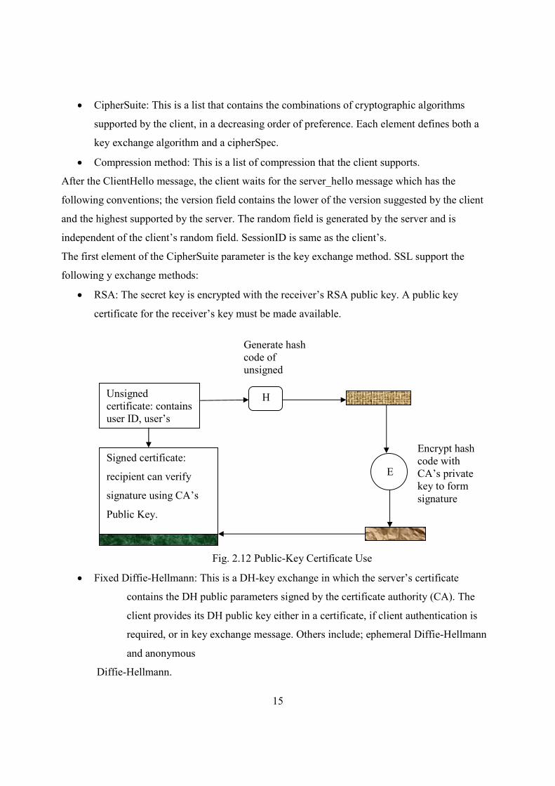
• RSA: The secret key is encrypted with the receiver’s RSA public key. A public key
certificate for the receiver’s key must be made available.
Fig. 2.12 Public-Key Certificate Use
• Fixed Diffie-Hellmann: This is a DH-key exchange in which the server’s certificate
contains the DH public parameters signed by the certificate authority (CA). The
client provides its DH public key either in a certificate, if client authentication is
required, or in key exchange message. Others include; ephemeral Diffie-Hellmann
and anonymous
Diffie-Hellmann.
Unsigned
certificate: contains
user ID, user’s
Generate hash
code of
unsigned
certificate
H
E
Signed certificate:
recipient can verify
signature using CA’s
Public Key.
Encrypt hash
code with
CA’s private
key to form
signature
16
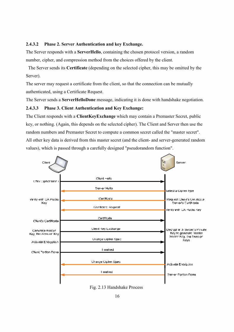
2.4.3.2 Phase 2. Server Authentication and key Exchange.
The Server responds with a ServerHello, containing the chosen protocol version, a random
number, cipher, and compression method from the choices offered by the client.
The Server sends its Certificate (depending on the selected cipher, this may be omitted by the
Server).
The server may request a certificate from the client, so that the connection can be mutually
authenticated, using a Certificate Request.
The Server sends a ServerHelloDone message, indicating it is done with handshake negotiation.
2.4.3.3 Phase 3. Client Authentication and Key Exchange:
The Client responds with a ClientKeyExchange which may contain a Premaster Secret, public
key, or nothing. (Again, this depends on the selected cipher). The Client and Server then use the
random numbers and Premaster Secret to compute a common secret called the "master secret".
All other key data is derived from this master secret (and the client- and server-generated random
values), which is passed through a carefully designed "pseudorandom function".
Fig. 2.13 Handshake Process
17
The Client now sends a Change Cipher Spec message, essentially telling the Server, "everything
I tell you from now on will be encrypted." Note that the ChangeCipherSpec is itself a record-level
protocol, and has type 20, and not 22.
Finally, the Client sends an encrypted Finished message, containing a hash and MAC over the
previous handshake messages.
The Server will attempt to decrypt the Client's Finished message, and verify the hash and MAC.
If the decryption or verification fails, the handshake is considered to have failed and the
connection should be torn down.
Phase 4. Finish: Finally, the Server sends a Change Cipher Spec and its encrypted Finished
message, and the Client performs the same decryption and verification.
At this point, the "handshake" is complete and the Application protocol is enabled, with content
type of 23. Application messages exchanged between Client and Server will be encrypted.
2.5 .0 Hashing Message Authentication Code HMAC/Hashing
Once the keys are exchanged using symmetric algorithm to secure tunnel, data can be sent [8].
There are two one would want to accomplish with data transfer. First is to make sure that what is
sent is the same as what is received on the other end. This is data integrity. Secondly, is to ensure
that when someone sends something, they cannot go back later and say they did not send it. This
is non-repudiation. To ensure data integrity, hash function is used. Data is run through a one way
function that creates a fixed length string (128 bits for MD5 and 160 bits for SHA1) of characters
and letters that represent the message. The message is sent along with this cryptographic summary
attached at the end. When the message is received, the receiver runs the message through the
same one way function and compares the results. If the strings match, then the receiver knows the
message has not been changed in the route. This way, data integrity is guaranteed. HMAC
prevents the hash strings from been removed
2.6.0 TLS Record Protocol
All records are compressed using the compression algorithm defined in the current session state.
The compression algorithm translates a SSL Plain text structure into a SSL Compressed structure.
Compression functions erase their state information whenever the Cipher Spec is replaced. All
records are protected using the encryption and MAC algorithms defined in the current Cipher
Spec. There is always an active Cipher Spec [7, 8].
18
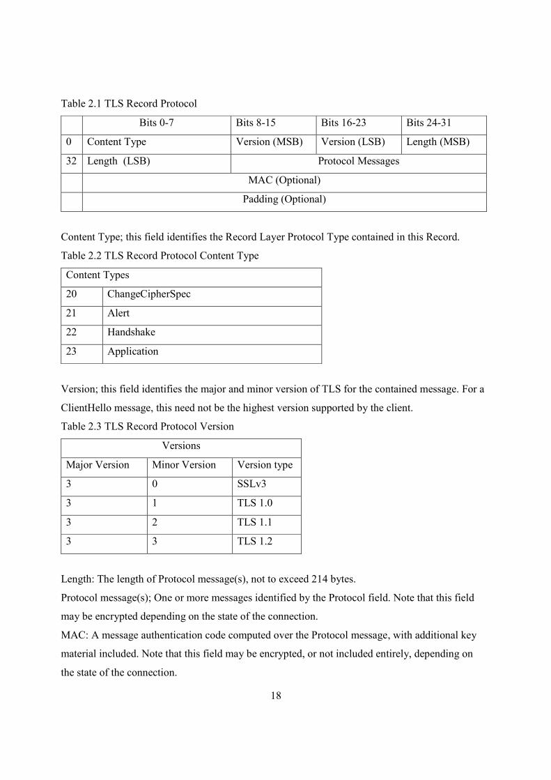
Table 2.1 TLS Record Protocol
Bits 0-7 Bits 8-15 Bits 16-23 Bits 24-31
0 Content Type Version (MSB) Version (LSB) Length (MSB)
32 Length (LSB) Protocol Messages
MAC (Optional)
Padding (Optional)
Content Type; this field identifies the Record Layer Protocol Type contained in this Record.
Table 2.2 TLS Record Protocol Content Type
Content Types
20 ChangeCipherSpec
21 Alert
22 Handshake
23 Application
Version; this field identifies the major and minor version of TLS for the contained message. For a
ClientHello message, this need not be the highest version supported by the client.
Table 2.3 TLS Record Protocol Version
Versions
Major Version Minor Version Version type
3 0 SSLv3
3 1 TLS 1.0
3 2 TLS 1.1
3 3 TLS 1.2
Length: The length of Protocol message(s), not to exceed 214 bytes.
Protocol message(s); One or more messages identified by the Protocol field. Note that this field
may be encrypted depending on the state of the connection.
MAC: A message authentication code computed over the Protocol message, with additional key
material included. Note that this field may be encrypted, or not included entirely, depending on
the state of the connection.
19
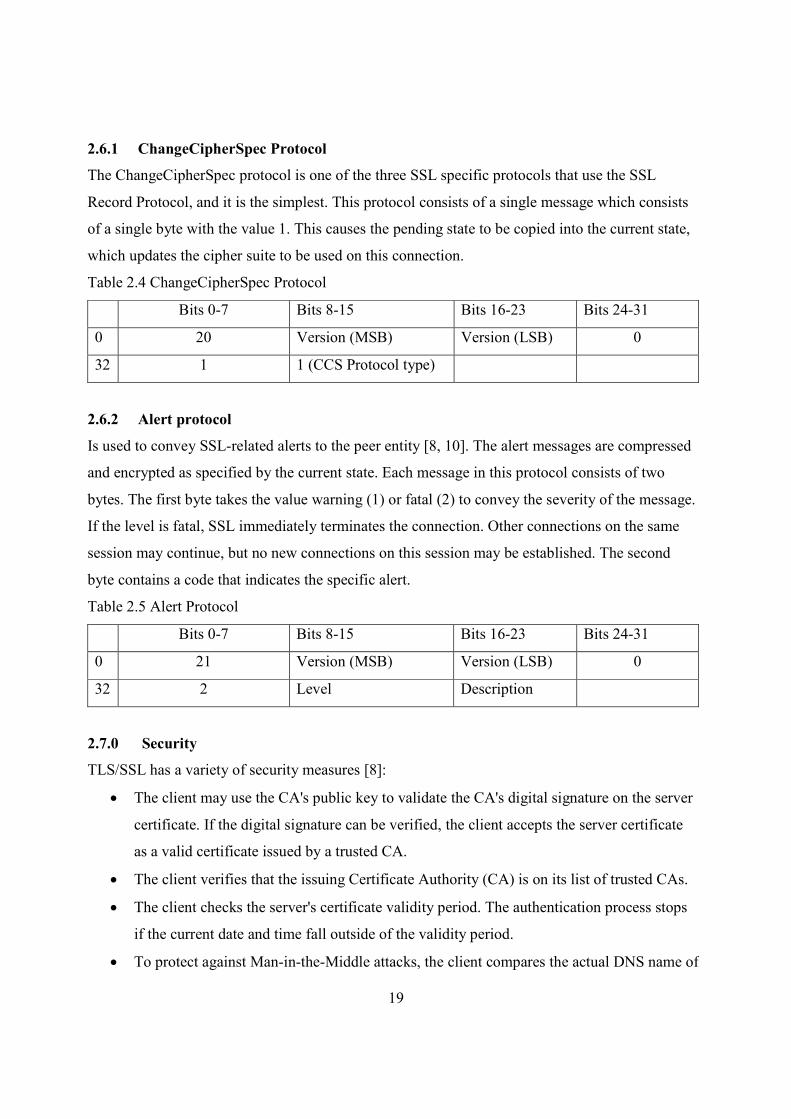
2.6.1 ChangeCipherSpec Protocol
The ChangeCipherSpec protocol is one of the three SSL specific protocols that use the SSL
Record Protocol, and it is the simplest. This protocol consists of a single message which consists
of a single byte with the value 1. This causes the pending state to be copied into the current state,
which updates the cipher suite to be used on this connection.
Table 2.4 ChangeCipherSpec Protocol
Bits 0-7 Bits 8-15 Bits 16-23 Bits 24-31
0 20 Version (MSB) Version (LSB) 0
32 1 1 (CCS Protocol type)
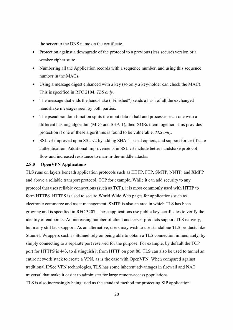
2.6.2 Alert protocol
Is used to convey SSL-related alerts to the peer entity [8, 10]. The alert messages are compressed
and encrypted as specified by the current state. Each message in this protocol consists of two
bytes. The first byte takes the value warning (1) or fatal (2) to convey the severity of the message.
If the level is fatal, SSL immediately terminates the connection. Other connections on the same
session may continue, but no new connections on this session may be established. The second
byte contains a code that indicates the specific alert.
Table 2.5 Alert Protocol
Bits 0-7 Bits 8-15 Bits 16-23 Bits 24-31
0 21 Version (MSB) Version (LSB) 0
32 2 Level Description
2.7.0 Security
TLS/SSL has a variety of security measures [8]:
• The client may use the CA's public key to validate the CA's digital signature on the server
certificate. If the digital signature can be verified, the client accepts the server certificate
as a valid certificate issued by a trusted CA.
• The client verifies that the issuing Certificate Authority (CA) is on its list of trusted CAs.
• The client checks the server's certificate validity period. The authentication process stops
if the current date and time fall outside of the validity period.
• To protect against Man-in-the-Middle attacks, the client compares the actual DNS name of
20
the server to the DNS name on the certificate.
• Protection against a downgrade of the protocol to a previous (less secure) version or a
weaker cipher suite.
• Numbering all the Application records with a sequence number, and using this sequence
number in the MACs.
• Using a message digest enhanced with a key (so only a key-holder can check the MAC).
This is specified in RFC 2104. TLS only.
• The message that ends the handshake ("Finished") sends a hash of all the exchanged
handshake messages seen by both parties.
• The pseudorandom function splits the input data in half and processes each one with a
different hashing algorithm (MD5 and SHA-1), then XORs them together. This provides
protection if one of these algorithms is found to be vulnerable. TLS only.
• SSL v3 improved upon SSL v2 by adding SHA-1 based ciphers, and support for certificate
authentication. Additional improvements in SSL v3 include better handshake protocol
flow and increased resistance to man-in-the-middle attacks.
2.8.0 OpenVPN Applications
TLS runs on layers beneath application protocols such as HTTP, FTP, SMTP, NNTP, and XMPP
and above a reliable transport protocol, TCP for example. While it can add security to any
protocol that uses reliable connections (such as TCP), it is most commonly used with HTTP to
form HTTPS. HTTPS is used to secure World Wide Web pages for applications such as
electronic commerce and asset management. SMTP is also an area in which TLS has been
growing and is specified in RFC 3207. These applications use public key certificates to verify the
identity of endpoints. An increasing number of client and server products support TLS natively,
but many still lack support. As an alternative, users may wish to use standalone TLS products like
Stunnel. Wrappers such as Stunnel rely on being able to obtain a TLS connection immediately, by
simply connecting to a separate port reserved for the purpose. For example, by default the TCP
port for HTTPS is 443, to distinguish it from HTTP on port 80. TLS can also be used to tunnel an
entire network stack to create a VPN, as is the case with OpenVPN. When compared against
traditional IPSec VPN technologies, TLS has some inherent advantages in firewall and NAT
traversal that make it easier to administer for large remote-access populations.
TLS is also increasingly being used as the standard method for protecting SIP application
21
signalling. TLS can be used to provide authentication and encryption of the SIP signalling
associated with VOIP (Voice over IP) and other SIP-based applications.
2.9.0 Client/Server Remote Access Vulnerabilities and Threats
When allowing remote sites and clients to connect to the corporate network over public networks,
security is an obvious concern. Many organizations have specific gatehouse guidelines that
require bastion hosts to be placed in or around the demilitarized zone (DMZ), and yet remote
VPN clients would fall in to the same category as the bastion hosts, since they can access the
internal network from outside the gateways [13].
2.9.1 Remote Client Security
The remote client represents the biggest challenge for remote access security. Authentication
process is the most critical aspect of securing clients connections. Even though this is obviously
imperative, it leaves out some other factors:
Unless the company provides all remote systems and mandates that only these can be
used, it is impossible to predict the history or settings on the clients.
Many remote access solutions do not allow for seamless awareness of Microsoft domains,
or it is difficult to mandate that the remote clients must be members of the domain. This
means that you will not be able to simply set group policies or logon scripts to ensure that
clients comply with corporate security policies.
Most remote access solutions need to provide connectivity solutions for all kinds of
clients, which makes specifying any scripts or security settings much more difficult
It is not possible to guarantee what happens with the client computer when the system is
not connected
2.10.0 Access Point Name (APN) on GPRS networks
An APN identifies a Packet Data Network (PDN) that is configured on and accessible from a
Gateway GPRS Support Node (GGSN). An access point is identified by its APN name. The
Global System for Mobile Communication (GSM) standard defines the following two parts of an
APN: APN Network Identifier and APN Operator Identifier The APN Network Identifier is
mandatory. The name of an access point in the form of an APN Network Identifier must
correspond to the fully-qualified name in the Domain Name System (DNS) configuration for that
network, and it must also match the name specified for the access point in the GGSN
configuration. The GGSN also uniquely identifies an APN by an index number. The APN
22
Operator Identifier is an optional name that consists of the fully-qualified DNS name, with the
ending “.gprs.” When a user requests a connection in the GPRS network, the APN is included in
the Create Packet Data Protocol (PDP) Request message. The Create PDP Request message is a
GPRS Tunneling Protocol (GTP) message that establishes a connection between the Serving
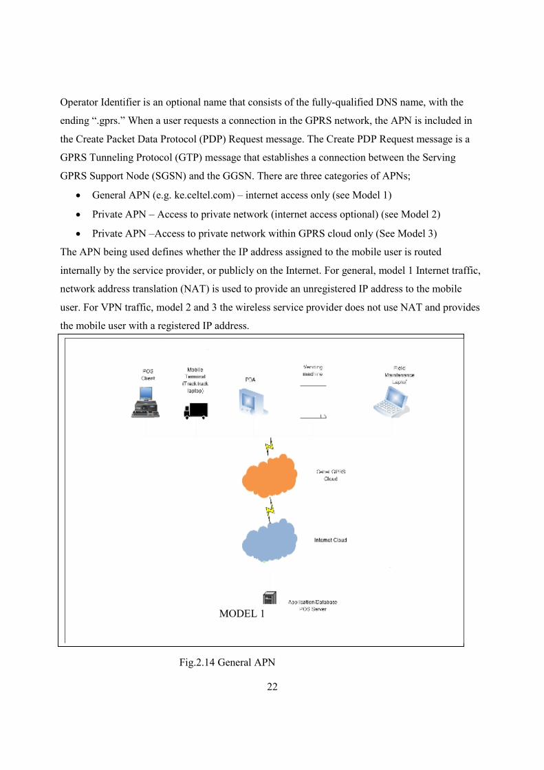
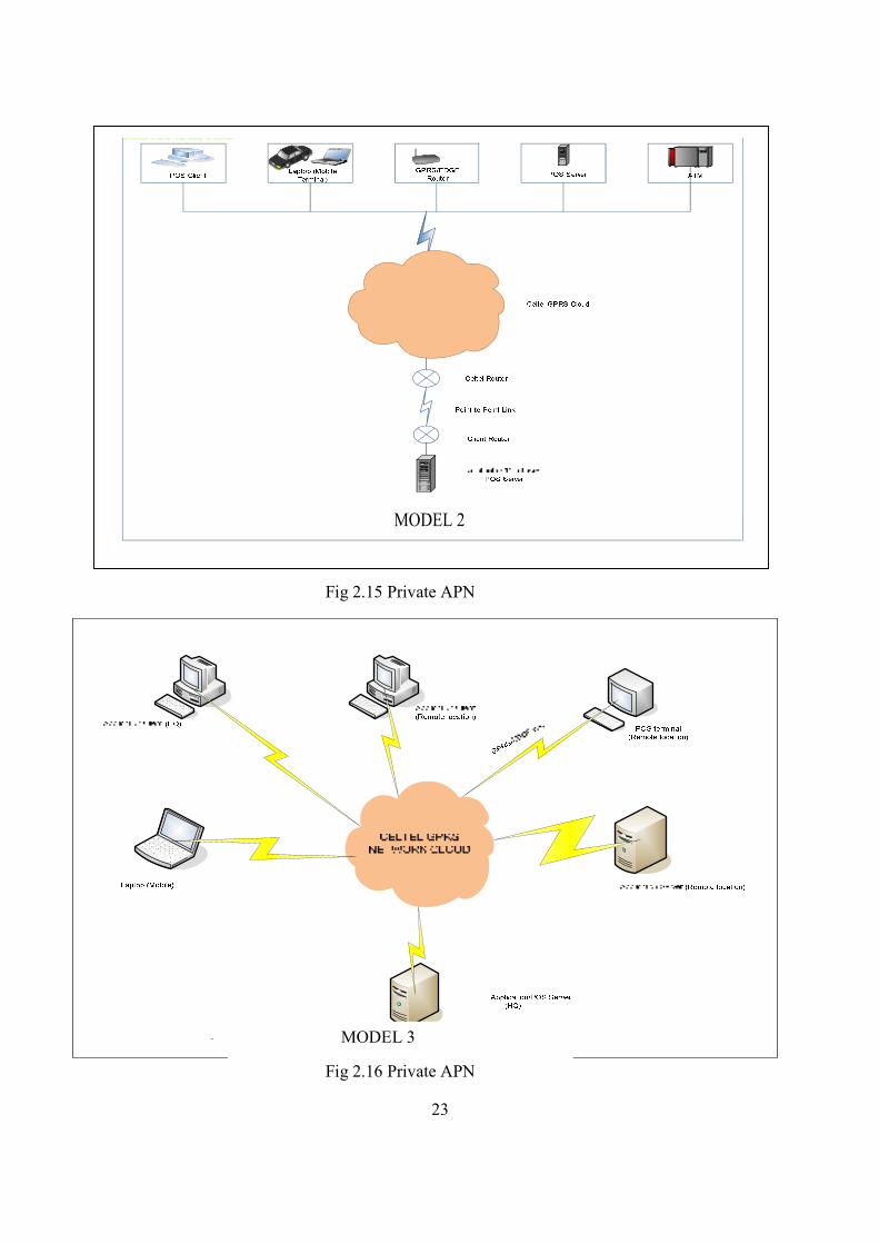
GPRS Support Node (SGSN) and the GGSN. There are three categories of APNs;
• General APN (e.g. ke.celtel.com) – internet access only (see Model 1)
• Private APN – Access to private network (internet access optional) (see Model 2)
• Private APN –Access to private network within GPRS cloud only (See Model 3)
The APN being used defines whether the IP address assigned to the mobile user is routed
internally by the service provider, or publicly on the Internet. For general, model 1 Internet traffic,
network address translation (NAT) is used to provide an unregistered IP address to the mobile
user. For VPN traffic, model 2 and 3 the wireless service provider does not use NAT and provides
the mobile user with a registered IP address.
MODEL 1
Fig.2.14 General APN
23
MODEL 2
Fig 2.15 Private APN
MODEL 3
Fig 2.16 Private APN
24
CHAPTER THREE: DESIGN AND METHODOLOGY
3.0.0 VPN For WAN/LAN Design
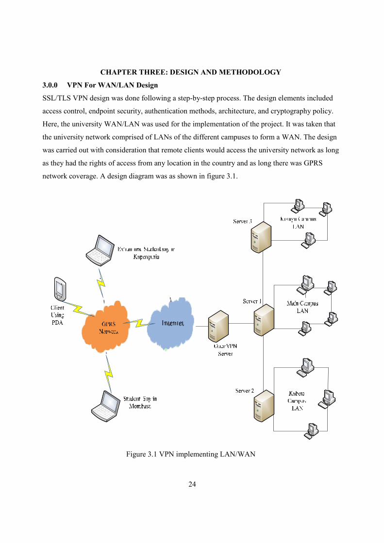
SSL/TLS VPN design was done following a step-by-step process. The design elements included
access control, endpoint security, authentication methods, architecture, and cryptography policy.
Here, the university WAN/LAN was used for the implementation of the project. It was taken that
the university network comprised of LANs of the different campuses to form a WAN. The design
was carried out with consideration that remote clients would access the university network as long
as they had the rights of access from any location in the country and as long there was GPRS
network coverage. A design diagram was as shown in figure 3.1.
Figure 3.1 VPN implementing LAN/WAN
25
3.1.0 Equipment Used;
1. Nokia 6300 with Orange SIM card
2. Laptop
3. OpenVPN software for both the client and the server
4. Wireshark LAN Sniffer
5. Server gateway at Chiromo
3.2.0 OpenVPN Software.
OpenVPN is a robust and highly flexible VPN daemon. OpenVPN supports SSL/TLS security,
Ethernet bridging, TCP or UDP tunnel transport through proxies or NAT, support for dynamic IP
address and DHCP, scalability to hundreds of users. OpenVPN is tightly bound to the Openssl
library, and derives much of its crypto capabilities from it.
OpenVPN supports convectional encryption using a pre-shared secret key (static key mode) or
public key security (SSL/TLS mode) using client and server certificates. On windows XP, Open
VPN was designed to work with the TUN/TAP virtual networking interface. OpenVPN allows
any option to be placed either on the command line or in a configuration file.
3.2.1 Installation of Open VPN.
Open VPN is open source software downloadable from http://www.openvpn.net. Open VPN for
windows was installed from the self executable exe file on both server and the client machines.
To run OpenVPN as a service was set in the Control Administrative tools Service. This was done
from the control panel i.e. menu->Control Panel->Administrative Tools->Services
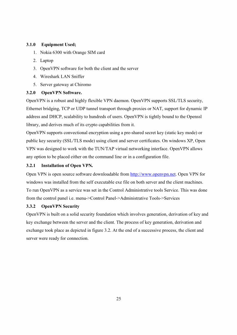
3.3.2 OpenVPN Security
OpenVPN is built on a solid security foundation which involves generation, derivation of key and
key exchange between the server and the client. The process of key generation, derivation and
exchange took place as depicted in figure 3.2. At the end of a successive process, the client and
server were ready for connection.
26
Figure 3.2 RSA Handshake Process
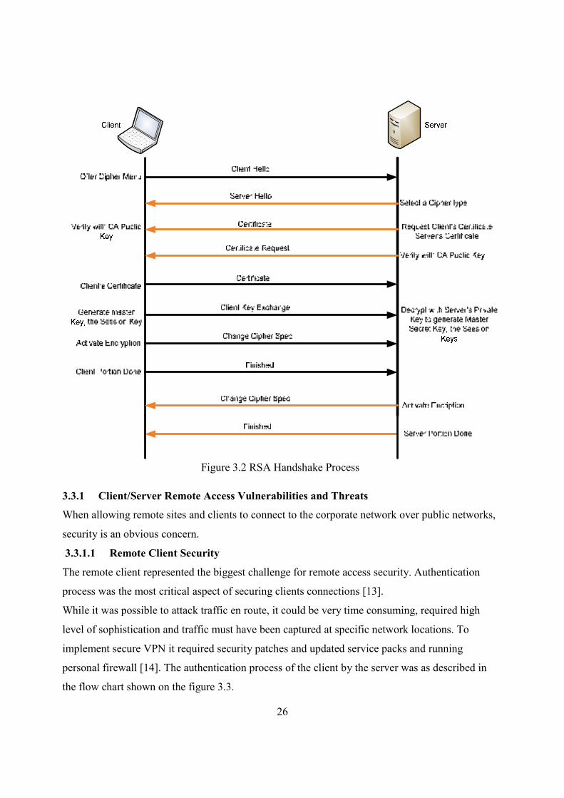
3.3.1 Client/Server Remote Access Vulnerabilities and Threats
When allowing remote sites and clients to connect to the corporate network over public networks,
security is an obvious concern.
3.3.1.1 Remote Client Security
The remote client represented the biggest challenge for remote access security. Authentication
process was the most critical aspect of securing clients connections [13].
While it was possible to attack traffic en route, it could be very time consuming, required high
level of sophistication and traffic must have been captured at specific network locations. To
implement secure VPN it required security patches and updated service packs and running
personal firewall [14]. The authentication process of the client by the server was as described in
the flow chart shown on the figure 3.3.
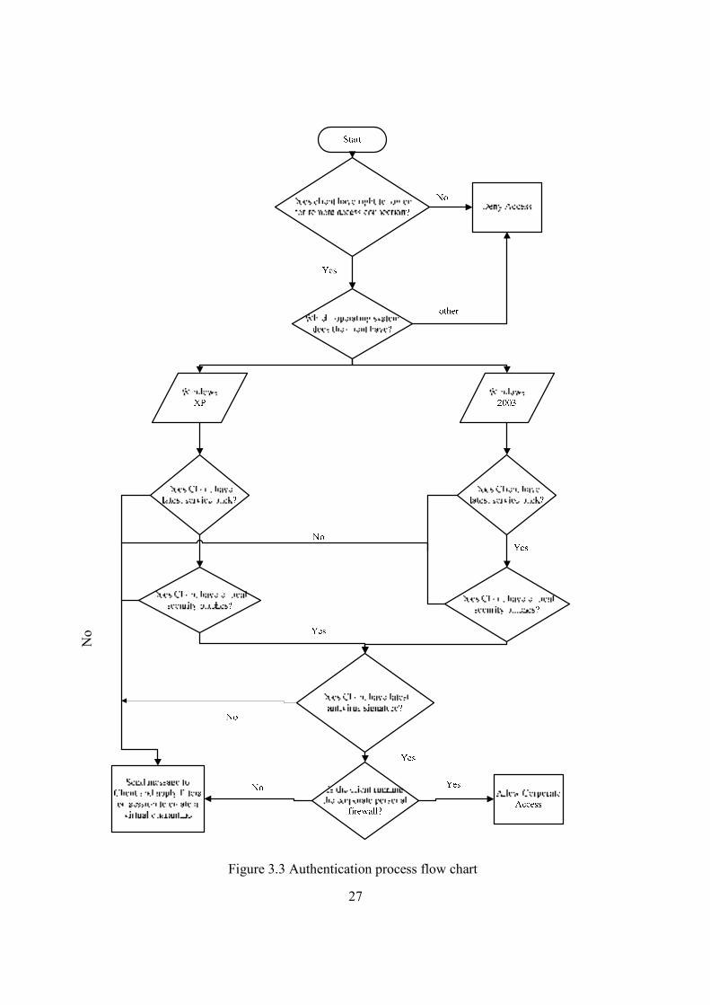
27
Figure 3.3 Authentication process flow chart
No
28
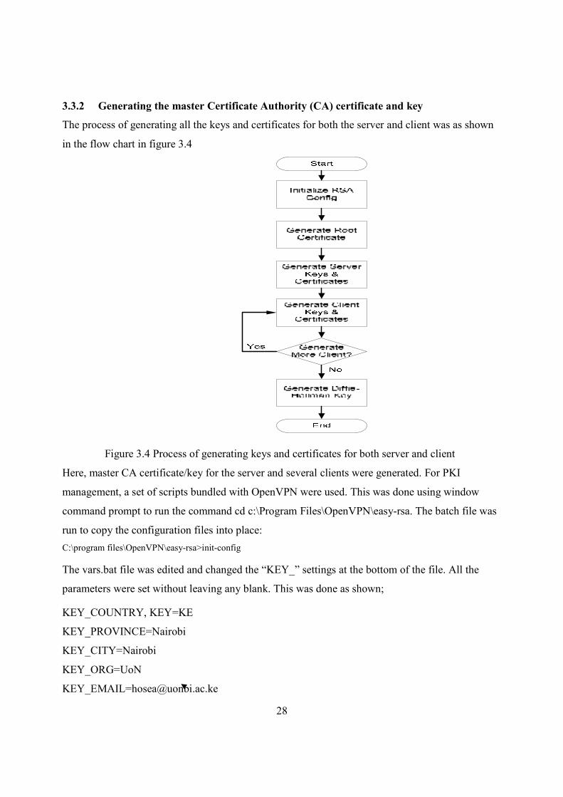
3.3.2 Generating the master Certificate Authority (CA) certificate and key
The process of generating all the keys and certificates for both the server and client was as shown
in the flow chart in figure 3.4
Figure 3.4 Process of generating keys and certificates for both server and client
Here, master CA certificate/key for the server and several clients were generated. For PKI
management, a set of scripts bundled with OpenVPN were used. This was done using window
command prompt to run the command cd c:\Program Files\OpenVPN\easy-rsa. The batch file was
run to copy the configuration files into place:
C:\program files\OpenVPN\easy-rsa>init-config
The vars.bat file was edited and changed the “KEY_” settings at the bottom of the file. All the
parameters were set without leaving any blank. This was done as shown;
KEY_COUNTRY, KEY=KE
KEY_PROVINCE=Nairobi
KEY_CITY=Nairobi
KEY_ORG=UoN
29
Next was to initialize the Public Key Infrastructure PKI. On the command line;
C:\Program Files\OpenVPN\easy-rsa>vars
C:\Program Files\OpenVPN\easy-rsa>clean-all
C:\Program Files\OpenVPN\easy-rsa>build-ca
The build-ca command build the Certificate Authority (CA) certificate and key by invoking the
interactive openssl command. Here information to be incorporated in the certificate request was
requested for, the Distinguished Name (DN). Most of the queried parameters by build-ca
command were defaulted to the values set in the vars.bat files. The only parameter which was
explicitly entered was the Common Name. In this case Testopenvpn was used as the common
name. The keys and certificate were created in the keys subfolder. The ca.crt (root certificate) was
copied to the OpenVPN config folder.
C:\Program Files\OpenVPN\easy-rsa>copy keys\ca.crt ..\config\
3.3.3 Generating certificate and key for server
Next, certificate and private key for the server were generated;
C:\Program Files\OpenVPN\easy-rsa>build-key-server server
Again, as in the above step, most parameters were defaulted apart from the Common Name. Two
other queries that required positive responses were "Sign the certificate? [y/n]" and "1 out of 1
certificate requests certified, commit? [y/n]".
3.3.4 Generating Certificate and Key for Several Clients
Clients’ keys and certificates were created on the OpenVPN server machine and securely copied
them to the client machine.
C:\Program Files\OpenVPN\easy-rsa>build-key Client1
C:\Program Files\OpenVPN\easy-rsa>build-key Client2
C:\Program Files\OpenVPN\easy-rsa>build-key Client3
…………
The client keys could be password-protected by substituting build-key with build-key-pass script.
Then each of the client’s key and certificate along with the root certificate were copied to the
configuration folder on the corresponding client machine. This was done by use of flash disk.
Note; The number of clients’ certificate and keys needed not to be just enough for the connecting
clients. To make work easier later when new clients needed to be included in the network, then, it
was wise to generate more clients’ certificate and keys than needed as of that time.
30
C:\Program Files\OpenVPN\easy-rsa>copy keys\Client1.crt d:\
C:\Program Files\OpenVPN\easy-rsa>copy keys\Client1.key d:\
C:\Program Files\OpenVPN\easy-rsa>copy keys\ca.crt d:\
Then on the client machines,
C:\Program Files\OpenVPN\easy-rsa>copy d:\Client1.crt ..\config\
C:\Program Files\OpenVPN\easy-rsa>copy d:\Client1.key ..\config\
C:\Program Files\OpenVPN\easy-rsa>copy d:\ca.crt ..\config\
3.3.5 Generating Diffie-Hellman Parameters
DH parameters were generated for the OpenVPN server by use of the command;
C:\Program Files\OpenVPN\easy-rsa>build-dh
This took time to generate.
The key, certificate and DH file were copied to the OpenVPN config folder.
C:\Program Files\OpenVPN\easy-rsa> copy keys\server.crt ..\config\
C:\Program Files\OpenVPN\easy-rsa> copy keys\server.key ..\config\
C:\Program Files\OpenVPN\easy-rsa> copy keys\dh1024.pem ..\config\
3.3.6 Creating Server Configuration file.
The server configuration file was created in the OpenVPN config folder (c:\program
files\OpenVPN\config\) as shown in appendix A2 (server configuration file settings).
In this case a maximum of four clients where each required TAP-Win32 virtual adapter
3.3.7 Creating Client(s) Configuration Files
Clients’ configuration files were created in the OpenVPN configuration folder (c:\program
files\OpenVPN\config\).Only the configuration file for one of the client was provided as shown in
appendix A1 since similar settings were required for the other clients’ configuration files apart
from the common name.
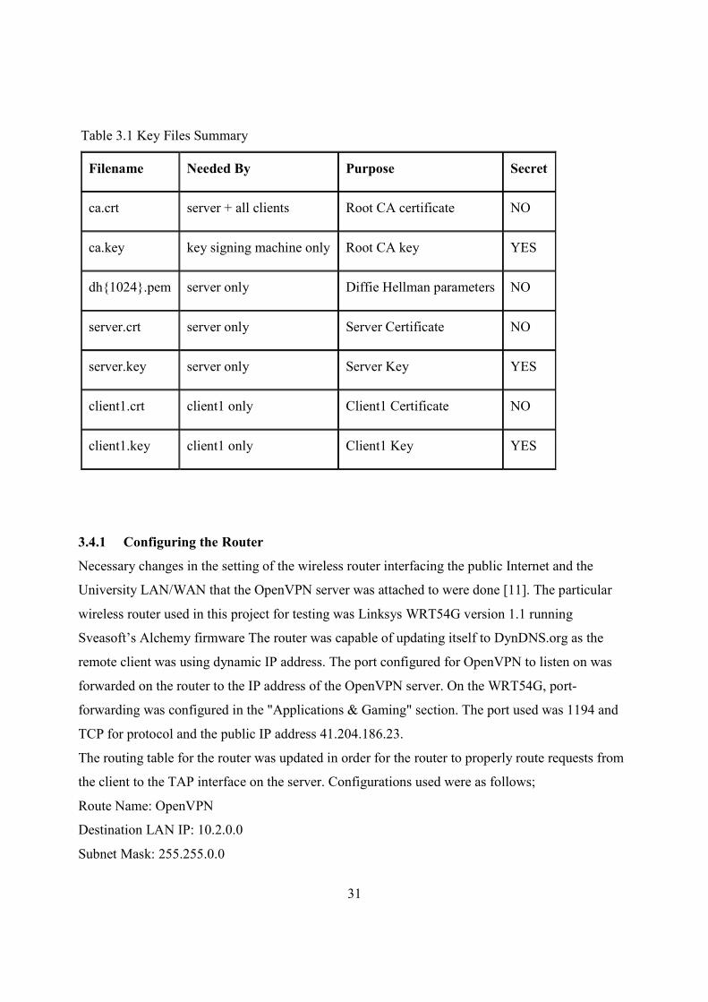
3.3.8 Summary of the Key Files
The generated keys and certificates were saved in their respective keys subdirectory. A
summary of the key files generated was given as shown in table 3.1
31
Table 3.1 Key Files Summary
Filename Needed By Purpose Secret
ca.crt server + all clients Root CA certificate NO
ca.key key signing machine only Root CA key YES
dh{1024}.pem server only Diffie Hellman parameters NO
server.crt server only Server Certificate NO
server.key server only Server Key YES
client1.crt client1 only Client1 Certificate NO
client1.key client1 only Client1 Key YES
3.4.1 Configuring the Router
Necessary changes in the setting of the wireless router interfacing the public Internet and the
University LAN/WAN that the OpenVPN server was attached to were done [11]. The particular
wireless router used in this project for testing was Linksys WRT54G version 1.1 running
Sveasoft’s Alchemy firmware The router was capable of updating itself to DynDNS.org as the
remote client was using dynamic IP address. The port configured for OpenVPN to listen on was
forwarded on the router to the IP address of the OpenVPN server. On the WRT54G, port-
forwarding was configured in the "Applications & Gaming" section. The port used was 1194 and
TCP for protocol and the public IP address 41.204.186.23.
The routing table for the router was updated in order for the router to properly route requests from
the client to the TAP interface on the server. Configurations used were as follows;
Route Name: OpenVPN
Destination LAN IP: 10.2.0.0
Subnet Mask: 255.255.0.0
32
Default Gateway: 10.2.21.8
Interface: LAN & Wireless
The above settings were saved afterward.
To allow VPN clients to communicate with systems on the LAN (other than the VPN server), it
was necessary to add the VPN network to the router configuration.
Network: 10.2.0.1
Subnet Mask: 255.255.0.0
Next Hop Address: 10.2.12.67
3.4.2 Configuring Windows XP Server
The windows XP server firewall was disabled as it would block OpenVPN traffic from passing
through the server. To enable the routing settings in the config file to work properly, the registry
key was edited as follows;
Routing registry key.reg (right-click, save, and run)
HKEY_LOCAL_MACHINE\SYSTEM\CurrentControlSet\Services\Tcpip\Parameters
IPEnableRouter = dword:00000001
3.4.3 Starting up the VPN and Testing for Initial Connectivity
To start up the OpenVPN, OpenVPN GUI icon was right clicked and selected “Connect”. The
status log opened showing the connection progress, if everything was working right then the
status log closed and the icon turned green showing the IP address assigned to it by the DHCP
server. A normal server and/or client start-up log file was as provided in chapter four.
To test the connection, pinging 41.204.186.23 (the server VPN IP address), 10.2.12.0 (the server
LAN IP address), the address of a PC on the remote LAN (e.g. 10.2.12.1), and then tried pinging
devices by name were done.
C:\> ping 41.204.186.87
C:\> ping 10.2.12.1
C:\> ping 10.2.12.0
C:\> ping server
If the ping succeeded, bravo, the VPN was functioning. The log files indicating successful VPN
connection were also as shown in chapter four.
33
3.4.4 Trouble Shooting
If the ping failed or OpenVPN client initialization failed to complete, possible symptoms and their
solutions might have included;
Message error;
i) TLS Error: TLS key negotiation failed to occur within 60 seconds. This error indicated
that the client was unable to establish a network connection with the server.
Possible solution;
• To make sure that the client was using the correct hostname/IP address and port number
which would allow it to reach the OpenVPN server
• For an OpenVPN server computer that was a single-NIC box inside a protected LAN, it
was made sure that the correct port forwarding rule was used on the server’s gateway
firewall.
• Opened up the server’s firewall to allow incoming connections to UDP port 1194.
ii) Initialization Sequence Completed with errors; This error could have occurred if the
client did not have the DHCP client running or a third party personal firewall was
turned on
Solution;
• Started the DHCP client server and made sure that the personal firewall running was
known by the operating system.
iii) The connection stalled on start up when using a proto udp configuration, the server log
file showed this line:
TLS: initial packet from x.x.x.x:x, sid=xxxx xxxx
But the client log file did not show any equivalent line.
Solution;
• There was one-way connection from client to server. The server to client direction was
blocked by a firewall, usually on the client side. The firewall could either be personal
running on the client or the NAT router gateway for the client. The firewall was modified
to allow returning UDP packets from the server to reach the client.
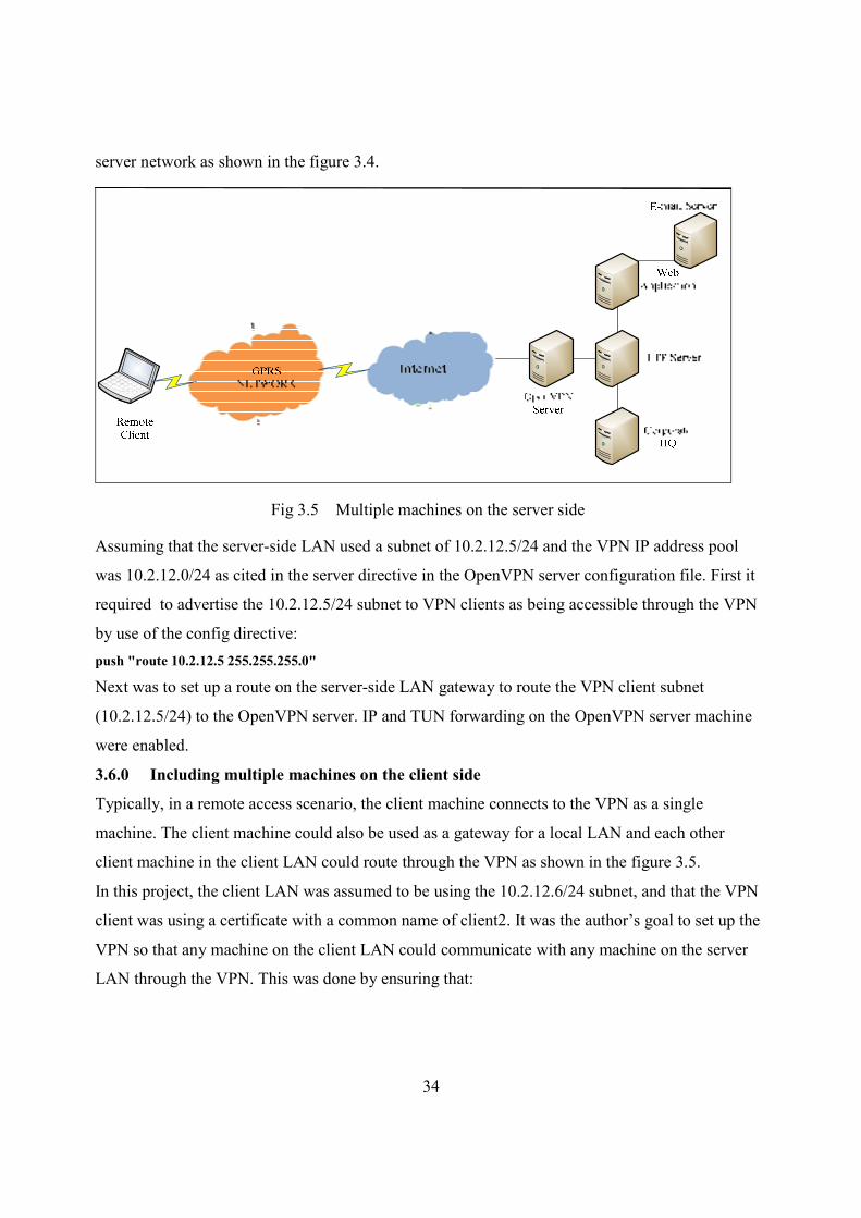
3.5.0 Including multiple machines on the server side when using a routed VPN (dev tun)
Once the VPN was operational in a point-to-point capacity between client and server, it could be
desirable to expand the scope of the VPN so that clients could reach multiple machines on the
34
server network as shown in the figure 3.4.
Fig 3.5 Multiple machines on the server side
Assuming that the server-side LAN used a subnet of 10.2.12.5/24 and the VPN IP address pool
was 10.2.12.0/24 as cited in the server directive in the OpenVPN server configuration file. First it
required to advertise the 10.2.12.5/24 subnet to VPN clients as being accessible through the VPN
by use of the config directive:
push "route 10.2.12.5 255.255.255.0"
Next was to set up a route on the server-side LAN gateway to route the VPN client subnet
(10.2.12.5/24) to the OpenVPN server. IP and TUN forwarding on the OpenVPN server machine
were enabled.
3.6.0 Including multiple machines on the client side
Typically, in a remote access scenario, the client machine connects to the VPN as a single
machine. The client machine could also be used as a gateway for a local LAN and each other
client machine in the client LAN could route through the VPN as shown in the figure 3.5.
In this project, the client LAN was assumed to be using the 10.2.12.6/24 subnet, and that the VPN
client was using a certificate with a common name of client2. It was the author’s goal to set up the
VPN so that any machine on the client LAN could communicate with any machine on the server
LAN through the VPN. This was done by ensuring that:
35
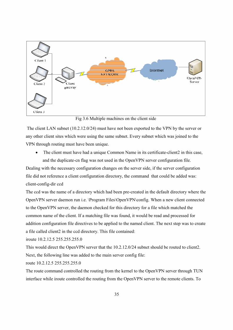
Fig 3.6 Multiple machines on the client side
The client LAN subnet (10.2.12.0/24) must have not been exported to the VPN by the server or
any other client sites which were using the same subnet. Every subnet which was joined to the
VPN through routing must have been unique.
• The client must have had a unique Common Name in its certificate-client2 in this case,
and the duplicate-cn flag was not used in the OpenVPN server configuration file.
Dealing with the necessary configuration changes on the server side, if the server configuration
file did not reference a client configuration directory, the command that could be added was:
client-config-dir ccd
The ccd was the name of a directory which had been pre-created in the default directory where the
OpenVPN server daemon run i.e. \Program Files\OpenVPN\config. When a new client connected
to the OpenVPN server, the daemon checked for this directory for a file which matched the
common name of the client. If a matching file was found, it would be read and processed for
addition configuration file directives to be applied to the named client. The next step was to create
a file called client2 in the ccd directory. This file contained:
iroute 10.2.12.5 255.255.255.0
This would direct the OpenVPN server that the 10.2.12.0/24 subnet should be routed to client2.
Next, the following line was added to the main server config file:
route 10.2.12.5 255.255.255.0
The route command controlled the routing from the kernel to the OpenVPN server through TUN
interface while iroute controlled the routing from the OpenVPN server to the remote clients. To
36
allow network traffic between client2’s subnet (10.2.12.5/24) and other clients of the OpenVPN
server the following commands were added to the server config file:
“client-to-client”
push "route 10.2.12.5 255.255.255.0"
This would cause the OpenVPN server to advertise client2’s subnet to other connecting clients.
Lastly, a route to the server’s LAN gateway was added which directs 10.2.12.5/24 to the
OpenVPN server box. When routing entire LANs through the VPN (when the VPN server not the
same machine as the LAN gateway), the gateway for the LAN was made route all VPN subnets to
the VPN server machine. Also if the client machine running OpenVPN was not the gateway for
the client LAN, then the gateway for the client LAN must have had a route which directed all
subnets which were meant to be reachable through the VPN to the OpenVPN client machine.
3.7.0 Implementing a load-balancing/ failover configuration
3.7.1 Client
The OpenVPN client configuration could refer to multiple servers for load balancing and failover.
For example:
remote server1.mydomain
remote server2.mydomain
remote server3.mydomain
and would direct the OpenVPN client to attempt a connection with server1, server2, and server3
in that order. If an existing connection was broken, the OpenVPN client would retry the most
recently, connected server, and if it failed, would move on to the next server in the list.
OpenVPN client could also be directed to randomize its server list on start-up, so that the client
load would be probabilistically spread across the server pool.
“remote-random”
3.7.2 Server
The simplest approach to a load-balanced/failover configuration on the server was to use
equivalent configuration files on each server in the cluster, except use a different virtual IP
address pool for each server. For example:
server1 “server 10.2.12.0 255.255.255.0”
server2 “server 10.2.18.0 255.255.255.0”
server3 “server 10.2.19.0 255.255.255.0”
37
CHAPTER FOUR: RESULTS AND ANALYSIS
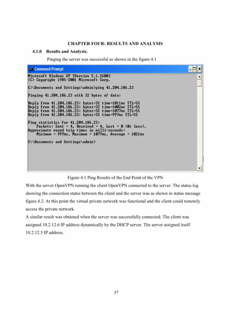
4.1.0 Results and Analysis.
Pinging the server was successful as shown in the figure 4.1
Figure 4.1 Ping Results of the End Point of the VPN
With the server OpenVPN running the client OpenVPN connected to the server. The status log
showing the connection status between the client and the server was as shown in status message
figure 4.2. At this point the virtual private network was functional and the client could remotely
access the private network.
A similar result was obtained when the server was successfully connected. The client was
assigned 10.2.12.6 IP address dynamically by the DHCP server. The server assigned itself
10.2.12.5 IP address.

38
Figure 4.2 OpenVPN Client Connection Status Log
39
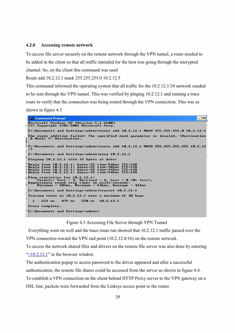
4.2.0 Accessing remote network
To access file server securely on the remote network through the VPN tunnel, a route needed to
be added in the client so that all traffic intended for the host was going through the encrypted
channel. So, on the client this command was used
Route add 10.2.12.1 mask 255.255.255.0 10.2.12.5
This command informed the operating system that all traffic for the 10.2.12.1/24 network needed
to be sent through the VPN tunnel. This was verified by pinging 10.2.12.1 and running a trace
route to verify that the connection was being routed through the VPN connection. This was as
shown in figure 4.3
Figure 4.3 Accessing File Server through VPN Tunnel
Everything went on well and the trace route run showed that 10.2.12.1 traffic passed over the
VPN connection toward the VPN end point (10.2.12.0/16) on the remote network.
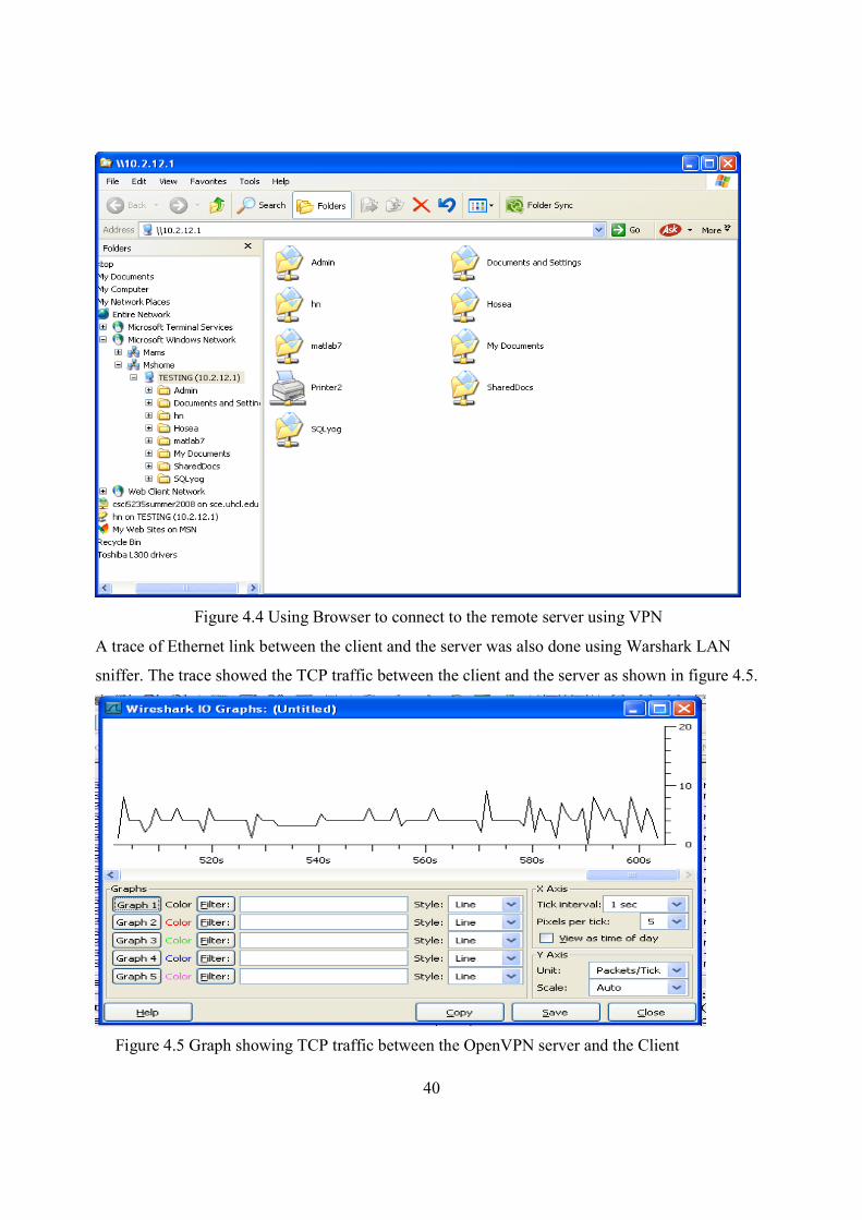
To access the network shared files and drivers on the remote file server was also done by entering
“\\10.2.12.1” in the browser window.
The authentication popup to access password to the drives appeared and after a successful
authentication, the remote file shares could be accessed from the server as shown in figure 4.4.
To establish a VPN connection on the client behind HTTP Proxy server to the VPN gateway on a
DSL line, packets were forwarded from the Linksys access point to the router.
40
Figure 4.4 Using Browser to connect to the remote server using VPN
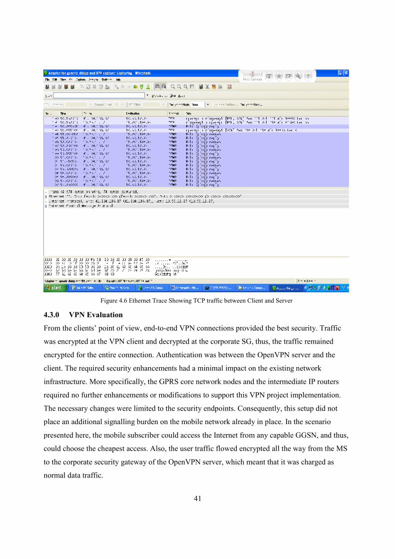
A trace of Ethernet link between the client and the server was also done using Warshark LAN
sniffer. The trace showed the TCP traffic between the client and the server as shown in figure 4.5.
Figure 4.5 Graph showing TCP traffic between the OpenVPN server and the Client
41
4.3.0 VPN Evaluation
From the clients’ point of view, end-to-end VPN connections provided the best security. Traffic
was encrypted at the VPN client and decrypted at the corporate SG, thus, the traffic remained
encrypted for the entire connection. Authentication was between the OpenVPN server and the
client. The required security enhancements had a minimal impact on the existing network
infrastructure. More specifically, the GPRS core network nodes and the intermediate IP routers
required no further enhancements or modifications to support this VPN project implementation.
The necessary changes were limited to the security endpoints. Consequently, this setup did not
place an additional signalling burden on the mobile network already in place. In the scenario
presented here, the mobile subscriber could access the Internet from any capable GGSN, and thus,
could choose the cheapest access. Also, the user traffic flowed encrypted all the way from the MS
to the corporate security gateway of the OpenVPN server, which meant that it was charged as
normal data traffic.
Figure 4.6 Ethernet Trace Showing TCP traffic between Client and Server
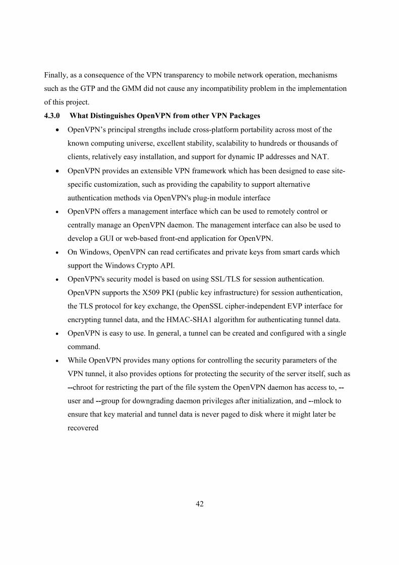
42
Finally, as a consequence of the VPN transparency to mobile network operation, mechanisms
such as the GTP and the GMM did not cause any incompatibility problem in the implementation
of this project.
4.3.0 What Distinguishes OpenVPN from other VPN Packages
• OpenVPN’s principal strengths include cross-platform portability across most of the
known computing universe, excellent stability, scalability to hundreds or thousands of
clients, relatively easy installation, and support for dynamic IP addresses and NAT.
• OpenVPN provides an extensible VPN framework which has been designed to ease site-
specific customization, such as providing the capability to support alternative
authentication methods via OpenVPN's plug-in module interface
• OpenVPN offers a management interface which can be used to remotely control or
centrally manage an OpenVPN daemon. The management interface can also be used to
develop a GUI or web-based front-end application for OpenVPN.
• On Windows, OpenVPN can read certificates and private keys from smart cards which
support the Windows Crypto API.
• OpenVPN's security model is based on using SSL/TLS for session authentication.
OpenVPN supports the X509 PKI (public key infrastructure) for session authentication,
the TLS protocol for key exchange, the OpenSSL cipher-independent EVP interface for
encrypting tunnel data, and the HMAC-SHA1 algorithm for authenticating tunnel data.
• OpenVPN is easy to use. In general, a tunnel can be created and configured with a single
command.
• While OpenVPN provides many options for controlling the security parameters of the
VPN tunnel, it also provides options for protecting the security of the server itself, such as
--chroot for restricting the part of the file system the OpenVPN daemon has access to, --
user and --group for downgrading daemon privileges after initialization, and --mlock to
ensure that key material and tunnel data is never paged to disk where it might later be
recovered
43
CHAPTER FIVE: CONCLUSION AND FURTHER WORK
5.1.0 CONCLUSION
In this document, an end-to-end remote access VPN scenario deployment over the GPRS mobile
network has been presented and analyzed. The VPN project implementation was based on the
SSL/TLS protocol suite. Specific protocol configuration of the complex SSL/TLS framework was
proposed and analysed, in order to make it operational in a mobile network environment.
Furthermore, for VPN initialization and key agreement procedures, a PKI (TLS handshake)
scheme were also discussed, which enabled the remote client to initiate a VPN connection, and
shifts the complex key negotiation to the network infrastructure. The object of the project was
realized. The performance was relative good as the GPRS modem used could only do up to
128Kb/s of data transfer. However with advanced 3G modem the data rate could be improved to
around 3Mb/s.
Finally, qualitative evaluations of the proposed remote access VPN scheme was discussed, and an
alternative network-based VPN scheme outlined for future work.
5.2.0 RECOMMENDATION FOR FURTHER WORK
When security is the main concern, the end-to-end VPN is an attractive solution. However,
alternative solution to the end-to-end VPN would be a network-based VPN. Under this approach,
the VPN functionality is outsourced to the GSN nodes and therefore, the main drawbacks, which
pertain to the end-to-end scheme, can be confined. However, the network-based VPN places the
SSL/TLS functionality within the GPRS core network, and thus, introduces a further burden on it.
Additionally, the biggest consideration is that the VPN operation is not directly under the end user
control. Network based virtual private network therefore could be considered for further work.
44
REFERENCES;
[1]. Vijay Bollapragada, Mohamed Khalid, Scott Wainner IPSec
VPN Design, Cisco Press, April 2005 page ISBN: 1-58705-111-7
[2]. Stallings W., “IP Security” Cisco, The Internet
Protocol Journal, vol 3, No 1, March 2000.
[3]. B. Gleeson, A. Lin, J. Heinanen, G. Armitage and
A. Malis “A Framework for IP Based Virtual Private
Networks” RFC 2764, Feb 2000.
[4]. Michael Borella, “Methods and Protocols for Secure
Key Negotiation Using IKE”, IEEE Network,
July/August 2000.
[5]. W. Diffie and M. E. Hellman, “New Directions in
Cryptography,” IEEE Trans. Info. Theory, vol. 22,
Nov 1976
[6]. Ruixi Y., Strayer T. (2001). Virtual Private Networks: Technologies and
Solutions. New York, New York: Addison Wesley.
[7]. Schneier, Bruce (1996). Applied Cryptography: Protocols, Algorithms, and
Source Code in C. New York, New York: John Wiley and Sons, Inc.
[8]. Viega J., Messier M., Chandra P. (2002). Network Security with OpenSSL.
Sebastopol, CA: O’Reilly.
[9]. S. Khanvilkar and A. Khokhar,“Virtual Private Networks: An Overview with
Performance Evaluation”
October 2004. IEEE Communications Magazine, pp. 146-154.
[10]. OpenVPN.[homepage on the Internet] Available from: http://openvpn.org [cited May
2005]
[11]. V. Gupta and S. Gupta, “Securing the Wireless Internet”. December 2001. IEEE
Communications
Magazine, pp. 68-74.
[12]. C. Xenakis, E. Gazis and L. Merakos, “Secure VPN Deployment in GPRS Mobile
Networks”. 2002.
45
Department of Informatics & Telecommunications, University of Athens
[13]. Robert Bragg, Mark Rhodes-ousley, Keith Strassberg, “Network Security”: The
complete reference, Tata McGraw-Hill Edition 2004 PP 247-262
[14]. Dr. GSO Odhiambo, “Telecommunication Lecture Manual: Communication networks”
University of Nairobi, Department of Electrical & Electronic Engineering, April 2007
[15]. Kipp E.B. Hickman�The SSL Protocol [M]. Netscape
Communication Corp, Feb,9th, 1995.
[16]. Alan O Freier, Philip Karlton, Paul C Kocher�The SSL
Protocol Version 3.0 [J].Internet Draft 302 IETF, 1996, pp 2-63.
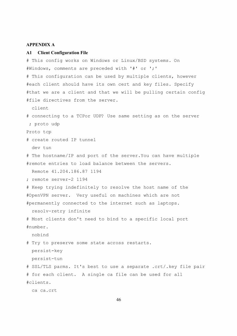
46
APPENDIX A
A1 Client Configuration File
# This config works on Windows or Linux/BSD systems. On
#Windows, comments are preceded with '#' or ';'
# This configuration can be used by multiple clients, however
#each client should have its own cert and key files. Specify
#that we are a client and that we will be pulling certain config
#file directives from the server.
client
# connecting to a TCPor UDP? Use same setting as on the server
; proto udp
Proto tcp
# create routed IP tunnel
dev tun
# The hostname/IP and port of the server.You can have multiple
#remote entries to load balance between the servers.
Remote 41.204.186.87 1194
; remote server-2 1194
# Keep trying indefinitely to resolve the host name of the
#OpenVPN server. Very useful on machines which are not
#permanently connected to the internet such as laptops.
resolv-retry infinite
# Most clients don't need to bind to a specific local port
#number.
nobind
# Try to preserve some state across restarts.
persist-key
persist-tun
# SSL/TLS parms. It's best to use a separate .crt/.key file pair
# for each client. A single ca file can be used for all
#clients.
ca ca.crt
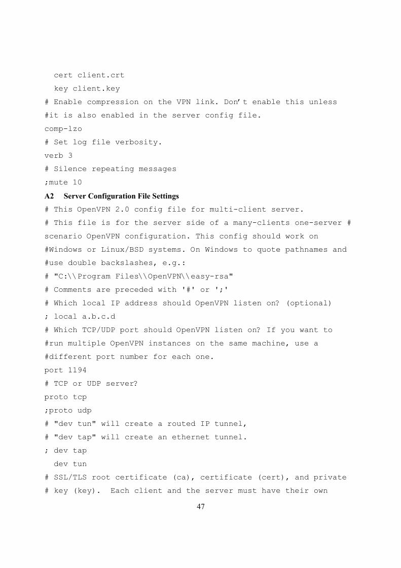
47
cert client.crt
key client.key
# Enable compression on the VPN link. Don’t enable this unless
#it is also enabled in the server config file.
comp-lzo
# Set log file verbosity.
verb 3
# Silence repeating messages
;mute 10
A2 Server Configuration File Settings
# This OpenVPN 2.0 config file for multi-client server.
# This file is for the server side of a many-clients one-server #
scenario OpenVPN configuration. This config should work on
#Windows or Linux/BSD systems. On Windows to quote pathnames and
#use double backslashes, e.g.:
# "C:\\Program Files\\OpenVPN\\easy-rsa"
# Comments are preceded with '#' or ';'
# Which local IP address should OpenVPN listen on? (optional)
; local a.b.c.d
# Which TCP/UDP port should OpenVPN listen on? If you want to
#run multiple OpenVPN instances on the same machine, use a
#different port number for each one.
port 1194
# TCP or UDP server?
proto tcp
;proto udp
# "dev tun" will create a routed IP tunnel,
# "dev tap" will create an ethernet tunnel.
; dev tap
dev tun
# SSL/TLS root certificate (ca), certificate (cert), and private
# key (key). Each client and the server must have their own
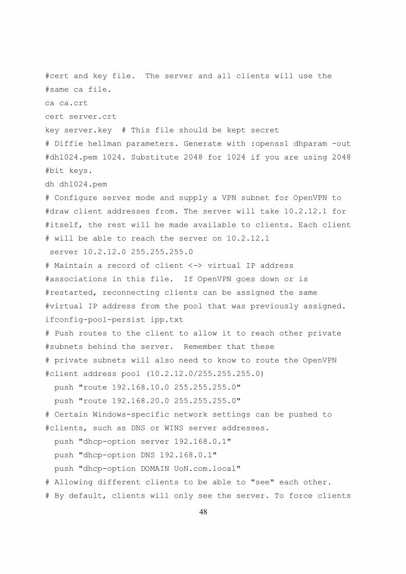
48
#cert and key file. The server and all clients will use the
#same ca file.
ca ca.crt
cert server.crt
key server.key # This file should be kept secret
# Diffie hellman parameters. Generate with :openssl dhparam -out
#dh1024.pem 1024. Substitute 2048 for 1024 if you are using 2048
#bit keys.
dh dh1024.pem
# Configure server mode and supply a VPN subnet for OpenVPN to
#draw client addresses from. The server will take 10.2.12.1 for
#itself, the rest will be made available to clients. Each client
# will be able to reach the server on 10.2.12.1
server 10.2.12.0 255.255.255.0
# Maintain a record of client <-> virtual IP address
#associations in this file. If OpenVPN goes down or is
#restarted, reconnecting clients can be assigned the same
#virtual IP address from the pool that was previously assigned.
ifconfig-pool-persist ipp.txt
# Push routes to the client to allow it to reach other private
#subnets behind the server. Remember that these
# private subnets will also need to know to route the OpenVPN
#client address pool (10.2.12.0/255.255.255.0)
push "route 192.168.10.0 255.255.255.0"
push "route 192.168.20.0 255.255.255.0"
# Certain Windows-specific network settings can be pushed to
#clients, such as DNS or WINS server addresses.
push "dhcp-option server 192.168.0.1"
push "dhcp-option DNS 192.168.0.1"
push "dhcp-option DOMAIN UoN.com.local"
# Allowing different clients to be able to "see" each other.
# By default, clients will only see the server. To force clients
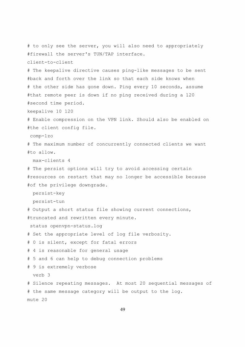
49
# to only see the server, you will also need to appropriately
#firewall the server's TUN/TAP interface.
client-to-client
# The keepalive directive causes ping-like messages to be sent
#back and forth over the link so that each side knows when
# the other side has gone down. Ping every 10 seconds, assume
#that remote peer is down if no ping received during a 120
#second time period.
keepalive 10 120
# Enable compression on the VPN link. Should also be enabled on
#the client config file.
comp-lzo
# The maximum number of concurrently connected clients we want
#to allow.
max-clients 4
# The persist options will try to avoid accessing certain
#resources on restart that may no longer be accessible because
#of the privilege downgrade.
persist-key
persist-tun
# Output a short status file showing current connections,
#truncated and rewritten every minute.
status openvpn-status.log
# Set the appropriate level of log file verbosity.
# 0 is silent, except for fatal errors
# 4 is reasonable for general usage
# 5 and 6 can help to debug connection problems
# 9 is extremely verbose
verb 3
# Silence repeating messages. At most 20 sequential messages of
# the same message category will be output to the log.
mute 20
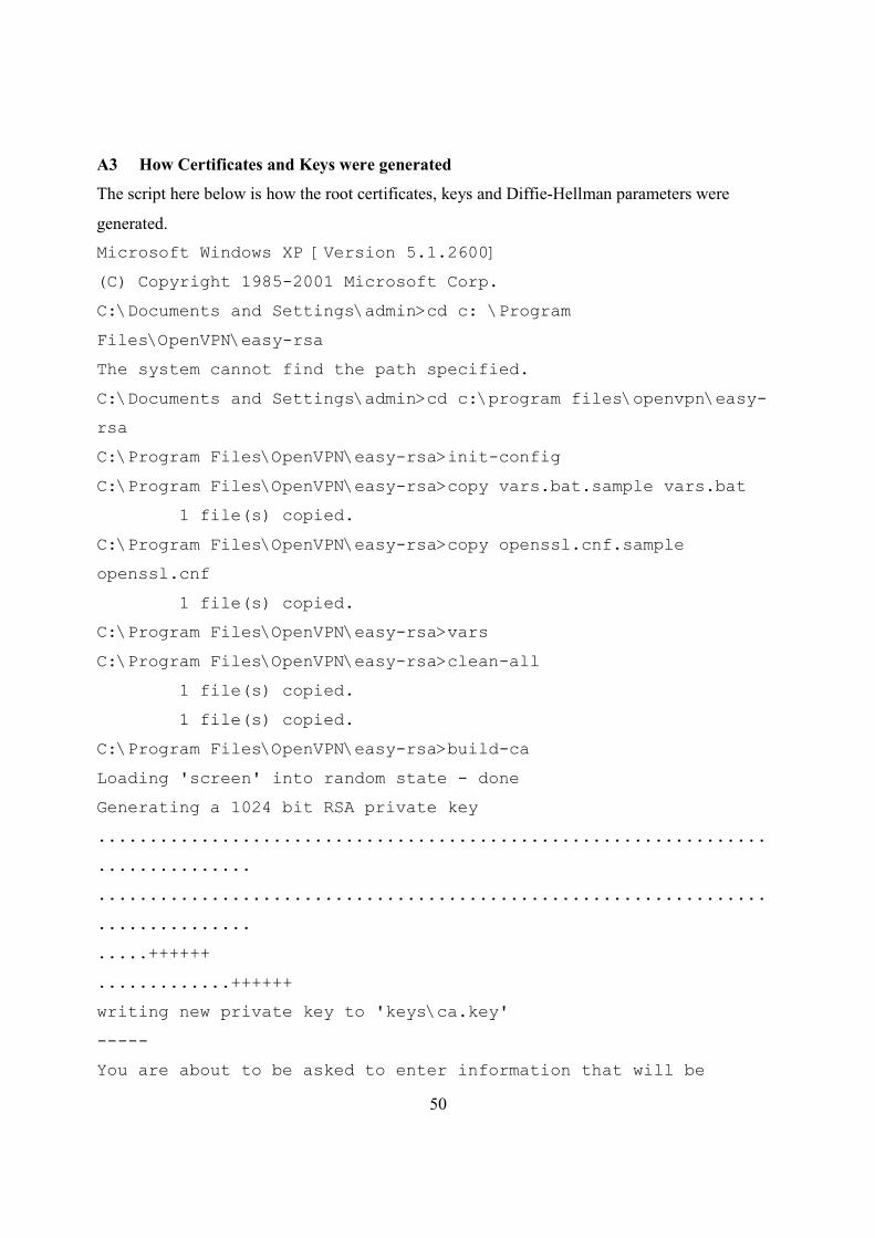
50
A3 How Certificates and Keys were generated
The script here below is how the root certificates, keys and Diffie-Hellman parameters were
generated.
Microsoft Windows XP [Version 5.1.2600]
(C) Copyright 1985-2001 Microsoft Corp.
C:\Documents and Settings\admin>cd c: \Program
Files\OpenVPN\easy-rsa
The system cannot find the path specified.
C:\Documents and Settings\admin>cd c:\program files\openvpn\easy-
rsa
C:\Program Files\OpenVPN\easy-rsa>init-config
C:\Program Files\OpenVPN\easy-rsa>copy vars.bat.sample vars.bat
1 file(s) copied.
C:\Program Files\OpenVPN\easy-rsa>copy openssl.cnf.sample
openssl.cnf
1 file(s) copied.
C:\Program Files\OpenVPN\easy-rsa>vars
C:\Program Files\OpenVPN\easy-rsa>clean-all
1 file(s) copied.
1 file(s) copied.
C:\Program Files\OpenVPN\easy-rsa>build-ca
Loading 'screen' into random state - done
Generating a 1024 bit RSA private key
.................................................................
...............
.................................................................
...............
.....++++++
.............++++++
writing new private key to 'keys\ca.key'
-----
You are about to be asked to enter information that will be
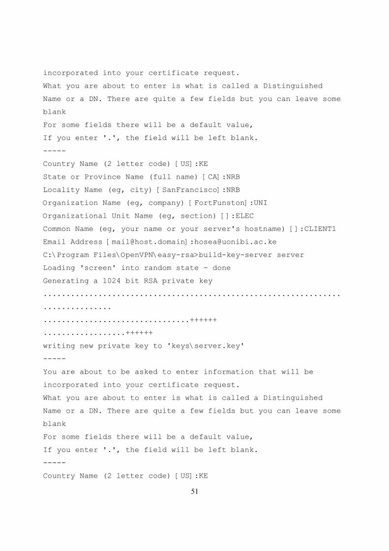
51
incorporated into your certificate request.
What you are about to enter is what is called a Distinguished
Name or a DN. There are quite a few fields but you can leave some
blank
For some fields there will be a default value,
If you enter '.', the field will be left blank.
-----
Country Name (2 letter code) [US]:KE
State or Province Name (full name) [CA]:NRB
Locality Name (eg, city) [SanFrancisco]:NRB
Organization Name (eg, company) [FortFunston]:UNI
Organizational Unit Name (eg, section) []:ELEC
Common Name (eg, your name or your server's hostname) []:CLIENT1
Email Address [[email protected]]:[email protected]
C:\Program Files\OpenVPN\easy-rsa>build-key-server server
Loading 'screen' into random state - done
Generating a 1024 bit RSA private key
.................................................................
...............
................................++++++
..................++++++
writing new private key to 'keys\server.key'
-----
You are about to be asked to enter information that will be
incorporated into your certificate request.
What you are about to enter is what is called a Distinguished
Name or a DN. There are quite a few fields but you can leave some
blank
For some fields there will be a default value,
If you enter '.', the field will be left blank.
-----
Country Name (2 letter code) [US]:KE
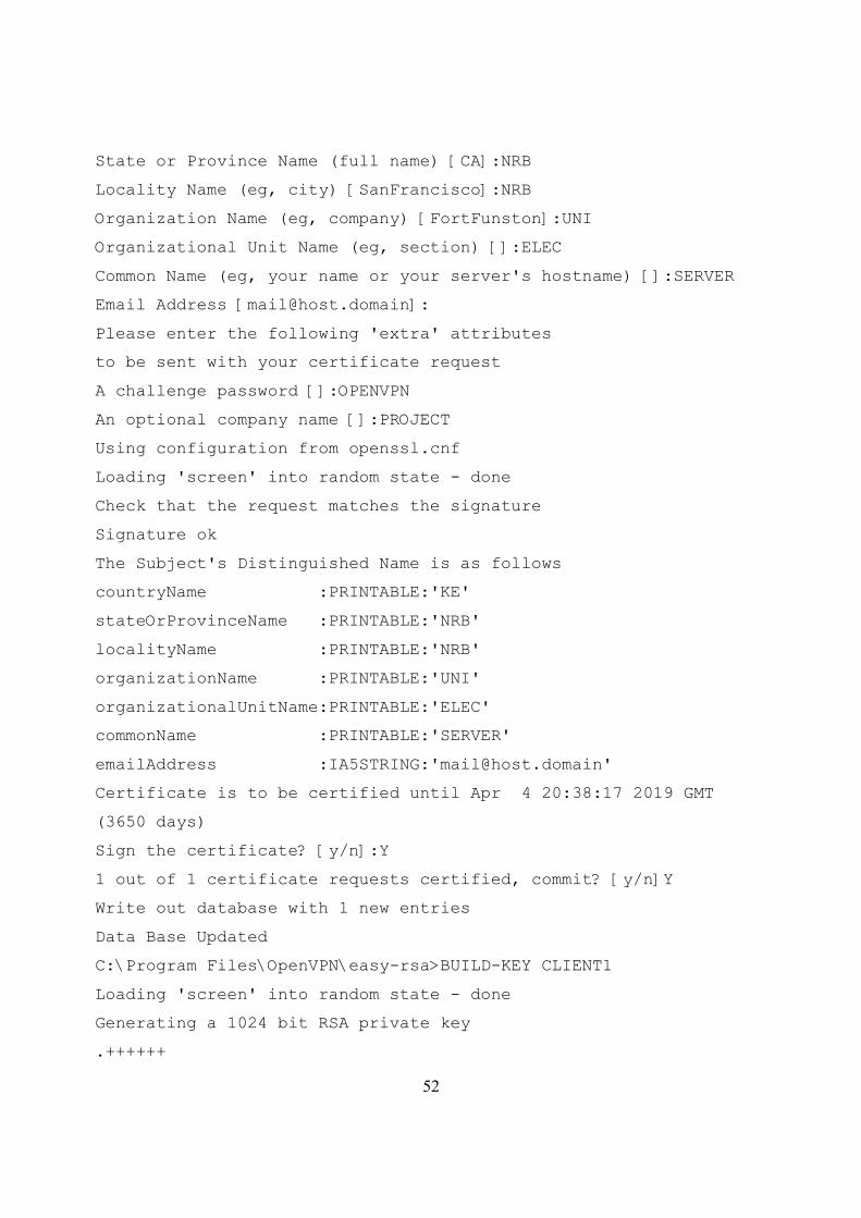
52
State or Province Name (full name) [CA]:NRB
Locality Name (eg, city) [SanFrancisco]:NRB
Organization Name (eg, company) [FortFunston]:UNI
Organizational Unit Name (eg, section) []:ELEC
Common Name (eg, your name or your server's hostname) []:SERVER
Email Address [[email protected]]:
Please enter the following 'extra' attributes
to be sent with your certificate request
A challenge password []:OPENVPN
An optional company name []:PROJECT
Using configuration from openssl.cnf
Loading 'screen' into random state - done
Check that the request matches the signature
Signature ok
The Subject's Distinguished Name is as follows
countryName :PRINTABLE:'KE'
stateOrProvinceName :PRINTABLE:'NRB'
localityName :PRINTABLE:'NRB'
organizationName :PRINTABLE:'UNI'
organizationalUnitName:PRINTABLE:'ELEC'
commonName :PRINTABLE:'SERVER'
emailAddress :IA5STRING:'[email protected]'
Certificate is to be certified until Apr 4 20:38:17 2019 GMT
(3650 days)
Sign the certificate? [y/n]:Y
1 out of 1 certificate requests certified, commit? [y/n]Y
Write out database with 1 new entries
Data Base Updated
C:\Program Files\OpenVPN\easy-rsa>BUILD-KEY CLIENT1
Loading 'screen' into random state - done
Generating a 1024 bit RSA private key
.++++++
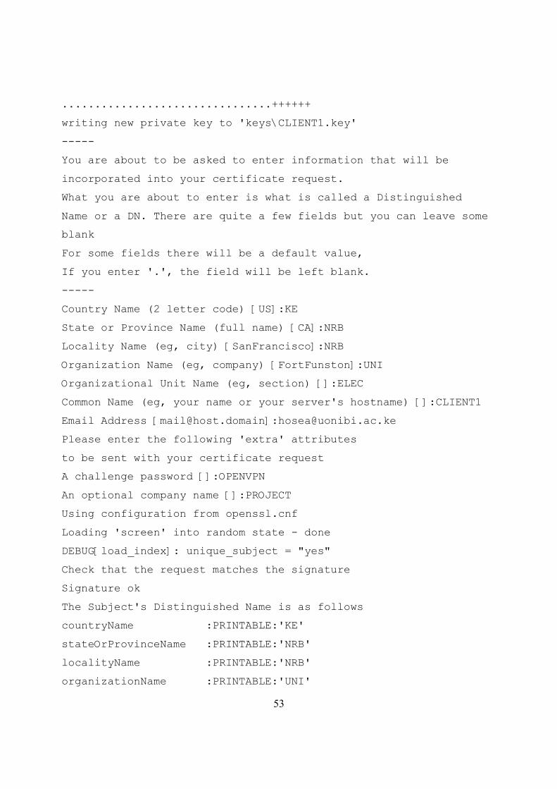
53
................................++++++
writing new private key to 'keys\CLIENT1.key'
-----
You are about to be asked to enter information that will be
incorporated into your certificate request.
What you are about to enter is what is called a Distinguished
Name or a DN. There are quite a few fields but you can leave some
blank
For some fields there will be a default value,
If you enter '.', the field will be left blank.
-----
Country Name (2 letter code) [US]:KE
State or Province Name (full name) [CA]:NRB
Locality Name (eg, city) [SanFrancisco]:NRB
Organization Name (eg, company) [FortFunston]:UNI
Organizational Unit Name (eg, section) []:ELEC
Common Name (eg, your name or your server's hostname) []:CLIENT1
Email Address [[email protected]]:[email protected]
Please enter the following 'extra' attributes
to be sent with your certificate request
A challenge password []:OPENVPN
An optional company name []:PROJECT
Using configuration from openssl.cnf
Loading 'screen' into random state - done
DEBUG[load_index]: unique_subject = "yes"
Check that the request matches the signature
Signature ok
The Subject's Distinguished Name is as follows
countryName :PRINTABLE:'KE'
stateOrProvinceName :PRINTABLE:'NRB'
localityName :PRINTABLE:'NRB'
organizationName :PRINTABLE:'UNI'
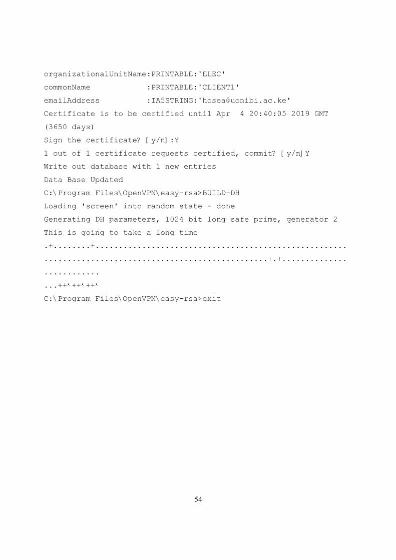
54
organizationalUnitName:PRINTABLE:'ELEC'
commonName :PRINTABLE:'CLIENT1'
emailAddress :IA5STRING:'[email protected]'
Certificate is to be certified until Apr 4 20:40:05 2019 GMT
(3650 days)
Sign the certificate? [y/n]:Y
1 out of 1 certificate requests certified, commit? [y/n]Y
Write out database with 1 new entries
Data Base Updated
C:\Program Files\OpenVPN\easy-rsa>BUILD-DH
Loading 'screen' into random state - done
Generating DH parameters, 1024 bit long safe prime, generator 2
This is going to take a long time
.+........+......................................................
................................................+.+..............
............
...++*++*++*
C:\Program Files\OpenVPN\easy-rsa>exit