Embed Size (px)
Citation preview
IiC F(IE COPY
Report No. CG-D-11-88
CD
PRELIMINARY SWEEP WIDTH DETERMINATION FORHU-25A AIRBORNE RADARS: LIFE RAFT AND
RECREATIONAL BOAT TARGETS
DTICkl -LECT
DEC 2 0 S R. 0. ROBE and M. J. LEWANDOWSKIU.& Coast Guard Research and Deveopment Center
Avery Point, Groton, Connecticut 06O-SM
... AND
G. L. HOVER and H. S. SEARLE
190 Gov. WInthrop BIvd, ecticut 06320-4223
INTERIM REPORT
DECEMBER 1987
This document Is available to the U.S. public through theNational Technical Information Service, Springfield, Virginia 22161
DISLMUTON STATEMENT APrepared for :Approved fox public telea ea
Distribution UDAMmted
U.S. Department of TransportationUnited States Coast GuardOffice of Engineering and DevelopmentWashington, DC 20593
38 12 20 029
..... .. ~~~~~~ 0 T I I E
NOTICE
This document Is disseminated under the sponsorship of theDepartment of Transportation In the Interest of Informationexchange. The United States Government assumes noliability for its contents or use thereof.
The United States Government does not endorse products ormanufacturers. Trade or manufacturers' names appear hereinsolely because they are considered essential to the object ofthis report.
The contents of this report reflect the views of the CoastGuard Research and Development Center, which isresponsible for the facts 4nd accuracy of date presented.This report does not constitute a standard, specification, orregulation.
/SAMUEL F. POWELj IIITechnical DirectorU.S. Coast Guard Research and Development CenterAvery Point, Groton, Connecticut 06340-6096
/ iI
U!

1. nw me.Tocheical ReW Deaumoee on peg*
4. Title *%d | | |. 3.w. 0...
Preliuinary Seep Width Determination For WU-25A December 1987'Airborne Radars: Life Raft and Recreational Boat ' e"-..a, opes.,,. C0deTargets
7. Awsho s
R.Q. Robe, N.J. Lewndowski. G.L. Hover, and H.S. Sear1, R&D C 03/889. Pew.mm.e O@mssNe MNe" 94.d Aidbess 10. We#% Usn. NW. (TRAIS)
U.S.C.G. RID Center Analysis & Technology, Inc.Avery Point 190 Governor Winthrop Blvd. I c........ o.. me.
Groton. CT 06340-96 New London. CT 06320-6223 DTC39-87-C-8049713. TV". so Jape s d p*f.d Cowefqd
12. Suam a A , s.d Add... Interim eportDepartment of Transportation Ine- eport
U.S. Coast Guard December 1987
Office of Engineering and Development 1, 6M,.eog Agee, Ced
Washington, D.C. 20593Is. supowm., NGM%This report is the twenty-third in a series which documents the Improvement inProbability of Detection in Search and Rosce(POO/SAR) Project at the U.S.C.G.
(R&D Center.14. Abeweet
' During June 1987, the U.S. Coast uard MD Center conducted a 3-week experimentto determine sweep widths for airborne radar search by Coast Guard HU-25A air-craft. Search objects were 6- to 10- person life rafts and 24- to 43-foot recre-ational-type boats. Two radar systems were evaluated: the AN/APS-127 formrd-looking airborne radar (FLAR) and the AM/APS-131 side-looking airborne radar(SLAR).
' Realistic radar searches were conducted to collect data using unalerted sensoroperators and standard search patterns. Aircraft and target positions were re-corded by a precision micrmve tracking system. Target detections and envi-ruental conditions wbre recorded by observers onboard the search aircraft anda target vessel. Sea conditions were dominated by wves less than 3 feet andwinds less than 12 knots, with a limited amount of data collected in 3- to 5-foot seas with winds up to 18 knots.
Analysis of the data confirmed that swep widths varied with significant sveheight, search altitude, and target size. Rcomended sweep width values andHU-25A search guidance are presented, along with recomendations for additionaldata collection. -
Search and Rescue, Airborne Radar, Docment is available to the U.S. PublicSide-Looking Airborne Radar, Sweep through the National Technical InformtiWidth, Electronic Search, Probability Service, Springfield, VA 22161of Detection
V. CIe . (04 e "Mo). 5~se, C1 1,. (of sw,' .'"*1. me. f pe"s 22. P"e.
UNCLASSIFIED7 UNCLASSIFIED
Fern DOT P 1700.7 (-S71 Reproduction nf form and c€npleted page is authorized022 122
ii.. m- m emmml i U
0 0 toC
oC to 0U-~~I o a . *.
0EU as 4w s C
I- D
> . Ot 0 -- Of
I- w0, Iz C J -
~0 0 -J-0~f
!-- E~ Cm
E. 0-o. 2E E2. 0EE 1
z 0LLA
8 9' 71 61 51 41 31 2 1 inches
0) a '5 1M) E EIE~ E Eg .g 0E-i. E E E
LL E10 -2~00
0.i
0 Co W w
00 u~ ~
> wl*I- 0.C) 0
C 0 1cc a
o a 71.S
mC1. U0 a. 0
>. .
iv

TABLE OF CONTENTS
EXECUTIVE SUMMARY ................................................................................ ix
ACKNOWLEDGEMENTS ............................................................................... xvi
1. INTRODUCTION ................................................................................... 1-1
1.1 SCOPE AND O ,JECTIVES ............................................................... 1-1
1.2 HU-25A RADAR SYSTEM DESCRIPTIONS .......................................... 1-1
1.2.1 AN/APS-127 FLAR ............................................................... 1-21.2.2 AN/APS-131 SLAR ............................................................... 1-4
1.3 EXPERIMENT DESCRIPTION ........................................................... 1-5
1.3.1 Participants .......................................................................... 1-51.3.2 Exercise Area ....................................................................... 1-71.3.3 Targets .............................................................................. 1-71.3.4 Experiment Design and Conduct ................................................. 1-71.3.5 Tracking and Reconstruction .................................................... 1-111.3.6 Range of Parameters Tested ..................................................... 1-16
1.4 ANALYSIS APPROACH ................................................................. 1-19
1.4.1 Measure of Search Performance ................................................. 1-191.4.2 Analysis of Search Data .......................................................... 1-22
1.4.2.1 Development of Raw Data ...................... . . ........... 1-221.4.2.2 LOGODDS Multivariate Regression Model ..................... 1-231.4.2.3 Least-Squares Curve Fits ........................................... 1-251.4.2.4 Sweep Width Calculations ......................................... 1-27
2. TEST RESULTS .................................................................................... 2-1
2.1 INTRODUCTION ........................................................................... 2-1
2.2 DETECTION PERFORMANCE ........................................................... 2-2
2.2.1 AN/APS-127 FLAR Detection Performance ................................... 2-2
2.2.1.1 FLAR Detection of Life Rafts ....................................... 2-22.2.1.2 FLAR Detection of Boats ............................................ 2-4
2.2.2 AN/APS-131 SLAR Detection Performance ................................... 2-10
2.2.2.1 SLAR Detection of Life Rafts ...................................... 2-102.2.2.2 SLAR Detection of Boats ........................................... 2-11
v
TABLE OF CONTENTS (Cont'd)
2.2.3 Combined FLAR/SLAR Detection Performance ....................... 2-13
2.3 TIME ON TASK EFFECTS.................................................. 2-16
3. CONCLUSIONS AND RECOMMENDATIONS .................................... 3-1
3.1 CONCLUSIONS............................................................3-1
3. 1.1 AN/APS- 127 FLAR Detection Performance........................... 3-13.1.2 AN/APS- 131 SLAR Detection Performance .......................... 3-23.1.3 General.............................................................. 3-2
3.2 RECOMM4ENDATIONS...................................................... 3-3
3.2.1 AN/APS- 127 FLAR Searches ........................................ 3-33.2.2 AN/APS-l131 SLAR Searches ........................................ 3-53.2.3 Combined FLAR/SLAR Searches .................................... 3-53.2.4 General Recommendations .......................................... 3-53.2.5 Recommendations for Future Research ............................... 3-5
REFERENCES..........................................................................R-1
APPENDIX A - RAW DATA............................................................ A-I
Q , Accesiori For
NTIS CRAMIDTIC TABUit1uinounced 0Jili 'ficat lon
ByDist; ibutinn I
Avlih~~Ity Codes
dv 'I orDist srpdcI di
vi

ILLUSTRATIONS
1-1 Exercise Area.....................................................................1-81-2 Examples of Radar Search Patterns Conducted by the HU-25A Aircraft..............1-91-3 Environmental Conditions Summary Forn......................................... 1-121-4 SLAR Detection Log............................................................. 1-131-5 FLAR Detection Log............................................................. 1-141-6 Visual Sighting Report Form ..................................................... 1-151-7 Aircraft Position Log............................................................. 1-171-8 Definition of Lateral Range ....................................................... 1-201-9 Relationship of Targets Detected to Targets Not Detected ........................... 1-201-10 Graphic and Pictorial Presentation of Sweep Width ................................ 1-211-11 S-Shaped Curves................................................................ 1-261-12 UnimodalCurve................................................................. 1-262-1 APS- 127 FLAR Detection of Life Rafts
(10-nmi range scale; seas < 2 feet) ................................................. 2-32-2 APS- 127 FLAR Detection of Life Rafts
(10-nmi range scale; seas 2 to 3 feet)................................................2-32-3 APS- 127 FLAR Detection of Life Rafts
(20-nmi range scale; all data) ...................................................... 2-42-4 APS-127 FLAR Detection of 24- to 43-foot Boats
(l0-nmi range scale; seas < 2 feet; 500-foot altitude)................................ 2-52-5 APS-127 FLAR Detection of 24- to 43-foot Boats
(10-nmi range scale; seas < 2 feet; 2500- to 5000-foot altitudes) ..................... 2-52-6 APS-127 FLAR Detection of 24- to 43-foot Boats
(10-nmi range scale; seas 2 to 5 feet; 2500- to 5000-foot altitudes) ................... 2-62-7 Target Tracks Relative to AN/APS- 127 FLAR PPI Display ......................... 2-72-8 APS-127 FLAR Detection of 24- to 27-foot Boats
(20-nmi range scale; all wave heights and altitudes combined)....................... 2-92-9 APS-127 FLAR Detection of 34- to 43-foot Boats
(20-nmi range scale; all wave heights and altitudes combined).......................2-92-10 APS-131 SLAR Detection of Life Rafts
(10-nmi range scale; aldata) ..................................................... 2-112-11 APS-131 SLAR Detection of 24- to 43-foot Boats
(10-nniirange scale; all data) ..................................................... 2-122-12 APS-131 SLAR Detection of 24- to 43-foot Boats
(20-nmi range scale; all data) ..................................................... 2-132-13 Combined FLAR/SLAR Detection of Life Rafts
(10-nmi range scale; seas < 2 feet; 2500- to 4500-foot search altitudes) .............. 2-142-14 Combined FLAR/SLAR Detection of Life Rafts
(10-nmi range scale; seas 2 to 3 feet; 2500- to 4500-foot altitudes)...................2-142-15 Combined FLAR/SLAR Detection of 24- to 43-foot Boats
(10-nmi range scale; seas < 2 feet; 2500- to 5000-foot search altitudes) .............. 2-152-16 Combined FLAR/SLAR Detection of 24- to 43-foot Boats
(10-nmi range scale; seas 2 to 5 feet; 2500- to 5000-foot search altitudes)............ 2-152-17 Effect of Time on Task on Target Detection Probability ............................ 2-17
vui
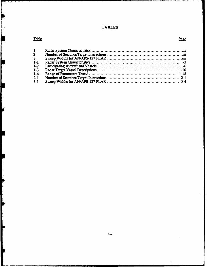
TABLES
1 Radar System Characteristics ........................................ x2 Number of Searcher/Target Interactions ......................................................... xii3 Sweep Widths for AN/APS- 127 FLAR ........................................................ xiii1-1 Radar System Characteristics .................................................................... 1-31-2 Participating Aircraft and Vessels ............................................................... 1-61-3 Radar Target Vessel Descriptions ............................................................... 1-101-4 Range of Parameters Tested ..................................................................... 1-182-1 Number of Searcher/Target Interactions ........................................................ 2-13-1 Sweep Widths for AN/APS-127 FLAR ........................................................ 3-4
viii
EXECUTIVE SUMMARY
INTRODUCTION
1. Bcgon
This report evaluates the detection performance of the AN/APS- 131 side-looking airborne
radar (SLAR), and the AN/APS-127 forward-looking airborne radar (FLAR) in detecting 6- to 10-person life rafts and a variety of work and pleasure boats in the 24- to 43-foot size range. In
support of this evaluation, an experiment was conducted during the period 2 to 28 June 1987 incoastal waters off Fort Pierce, Florida, by the United States Coast Guard Research andDevelopment Center (R & D Center). Coast Guard Air Station Miami provided an HU-25A
aircraft equipped with the APS-131 SLAR and APS-127 FLAR to collect sensor performance data.
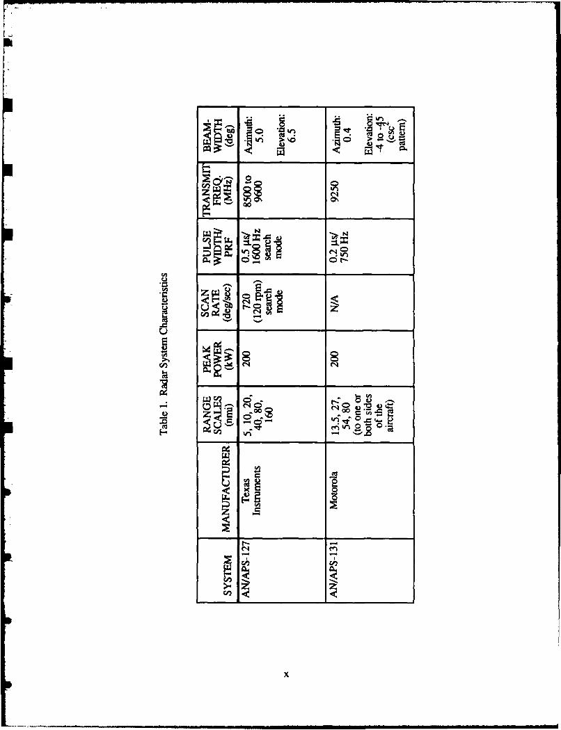
2. AN/APS-127 System Descriotion
The AN/APS-127 FLAR is an x-band air-to-surface search radar developed to detect smalltargets in a sea clutter environment. Pertinent system data are summarized in table 1. FLAR
detection performance data were collected using a 7-inch plan position indicator (PPI) in ground-
stabilized mode.
3. AN/APS.131 System Descriotion
The AN/APS-131 SLAR is an x-band surveillance and oil slick detection system derivedfrom the AN/APS-135 SLAR used on Coast Guard HC-130 aircraft. The AN/APS-131 is one of
five components that comprise the AN/ASD-6 AIREYE system. Pertinent system data are
summarized in table 1. The SLAR imagery is produced in a near-real time video format using the
AIREYE multipurpose display (MPD) or on a permanent copy dry-silver film.
ix
L=bO ~O ~'r~ '~jtl
U2o o
U CIO
cnz

4. Anwllacl
Data were collected using unalerted sensor operators and standard search patterns. Aircraft
and target positions were recorded by a precision microwave tracking system. Target detections
and environmental conditions were recorded by observers onboard the search aircraft and a target
vessel.
Data reconstruction was performed to determine detection and closest point of approach
(CPA) ranges for each target opportunity. Raw data files were developed for each search day and
entered into a VAX 11/780 computer for analysis.
FLAR and SLAR detection performance levels were evaluated independently and combined
sensor search performance was estimated analytically. The influence of interactions among
primary search parameters of interest were investigated using a sophisticated binary multivariate
regression analysis technique.
RESULTS AND CONCLUSIONS
1. Results
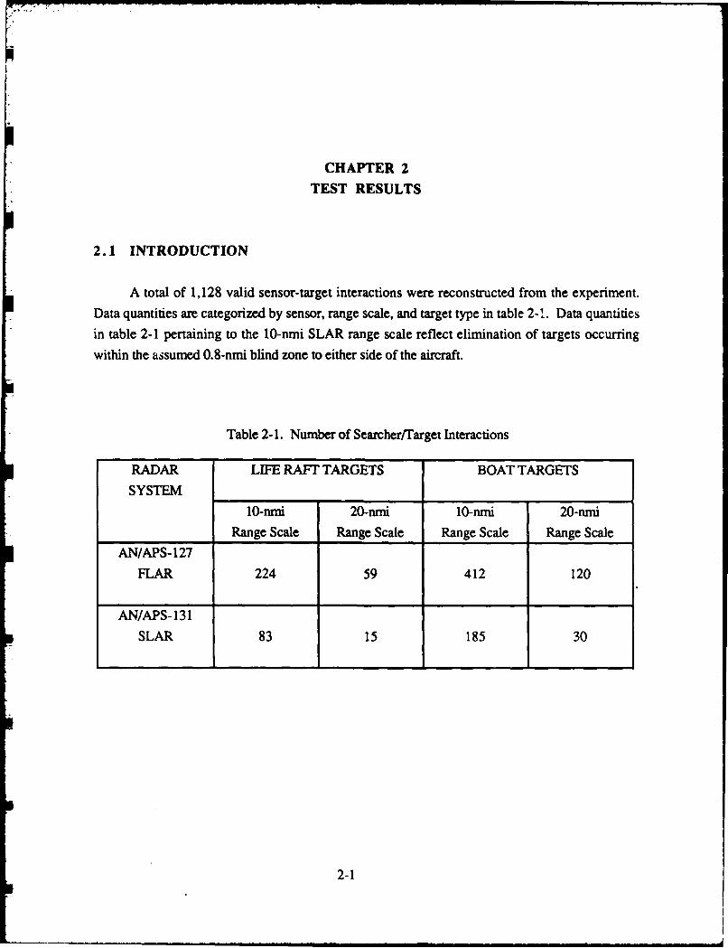
A total of 1,128 valid sensor-target interactions were reconstructed from the experiment.
Data quantities categorized by sensor, range scale, and target type are shown in table 2. Sea
conditions during the experiment were dominated by waves less than 3 feet and winds less than 12
knots, with a limited amount of data collected in 3- to 5-foot seas with winds up to 18 knots.
Least-squares fitted lateral range curves and sweep width estimates were developed for
each significant sensor/target/search parameter combination identified during data analysis.
2. C.nclulns
o The AN/APS-127 FLAR provides a useful detection capability against boats and life
rafts. Search altitude, significant wave height, and target size were found during
regression analysis to exert significant influence on FLAR target detection probability.
xi

o The AN/APS-131 SLAR provides a useful detection capability against boats and life
rafts. Target size was found to exert a significant influence on target detection
probability.
o Target detection probability was influenced by time on task in two ways. During the
first half-hour of a sortie, collateral operator duties and sensor adjustments appear to
have a negative effect. After approximately 1.5 hours' time on task, fatigue appears to
exert a negative influence.
Table 2. Number of Searcher/Target Interactions
RADAR LIFE RAFT TARGETS BOAT TARGETS
SYSTEM
10-nmi 20-nmi 10-nmi 20-nmi
Range Scale Range Scale Range Scale Range Scale
AN/APS-127
FLAR 224 59 412 120
AN/APS-131
SLAR 83 15 185 30
RECOMMENDATIONS
1. AN/APS-127 FLAR Searches
o The sweep widths provided in table 3 should be used by Coast Guard search planners
to represent the FLAR search performance of HU-25A aircraft.
xii
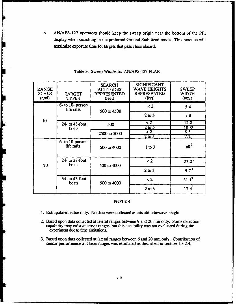
o AN/APS-127 operators should keep the sweep origin near the bottom of the PPIdisplay when searching in the preferred Ground Stabilized mode. This practice willmaximize exposure time for targets that pass close aboard.
Table 3. Sweep Widths for AN/APS-127 FLAR
SEARCH SIGNIFICANTRANGE ALTITUDES WAVE HEIGHTS SWEEPSCALE TARGET REPRESENTED REPRESENTED WIDTH(nmi) TYPES (feet) (feet) (nmi)
6- to 10-person <2 5.4life rafts 500 to 4500
2 to 3 1.810 24- to 43-foot 500 <2 12.8
boats 2 to 5 10.8 1
2500 to 5000 <2 8.52 to 5 7.2
6- to 10-personlife rafts 500 to 4000 1 to 3 nil
24- to 27-foot <2 23.2'20 boats 500 to 4000
2 to 3 9.73
34- to 43-foot <2 31.13boats 500 to4000
2 to 3 17.4 3
NOTES
1. Extrapolated value only. No data were collected at this altitude/wave height.
2. Based upon data collected at lateral ranges between 9 and 20 nmi only. Some detectioncapability may exist at closer ranges, but this capability was not evaluated during the
experiment due to time limitations.
3. Based upon data collected at lateral ranges between 6 and 20 nmi only. Contribution ofsensor performance at closer raages was estimated as described in section 1.3.2.4.
xiii

o ANIAPS-127 searches should be conducted at 500 feet whenever flight operationspermit. When higher search altitudes must be used due to weather, air traffic, or theoperating requirements of other onboard sensors/systems, degraded sweep width
estimates should be used where available in table 3.
2. AN/APS-131 SLAR Searches
o Based on previous analyses, 2500- to 4000-foot search altitudes should be used when
searching with the AN/APS-131 SLAR for small targets.
o The SLAR overheating problems experienced during this evaluation should beinvestigated and alleviated, if possible, to improve sensor reliability.
3. Combined FLAR/SLAR Searches
o When both sensor operators are FLAR- and SLAR-qualified, they should consider
exchanging positions near the midpoint of a search sortie.
4. General Recommendations
o Sufficient time should be provided prior to commencing search for electronic sensoroperators to initialize and adjust their equipment. Collateral operator duties other thanthe search task should also be completed prior to commencing search.
5. Recommendations for Future Research
o Additional data should be collected using the 20-nmi range scale of the AN/APS- 127FLAR against 20- to 45-foot boat targets. Special emphasis should be placed onobtaining some of the detection opportunities at lateral ranges less than 10 nmi.
o Additional data should be collected using the 20-nmi swath width of the AN/APS- 131
SLAR against 20- to 45-foot boats and life rafts.
xiv

o Additional data should be collected using the I 0-ni range scale of the AN/APS-127
FLAR against raft targets. Specifically, the 500-foot search altitude should be
evaluated in 2- to 5-foot seas.
o The FLAR and SLAR sensors should be further evaluated against boats in seas greater
than 4 feet.
o The detection performance of longer SLAR range scales should be investigated against
appropriate SAR targets when resources become available.
xv
ACKNOWLEDGEMENTS
The authors would like to acknowledge the support and cooperation of the Seventh Coast
Guard District staff, Coast Guard Air Station Miami, Coast Guard Station Fort Pierce, and the
Coast Guard Aids to Navigation Team Miami without whom the experiment would not have been
possible. We would like to especially thank the Coast Guard Auxiliary units of the 7th District for
assisting us with their time and their boats. We would like to acknowledge the advice and critical
review provided by Dr. David Paskausky during the planning and analysis phases of this
experiment. The time and effort of the following people from the R&D Center, Analysis &
Technology, Inc., Florida Atlantic University, and Input Output Computer Services, Inc. was
essential to the success of this experiment and is greatly appreciated: A. Allen, M. Couturier,
S. Eynon, T. Johnson, S. Shedlack, and C. Wellman.
xvi

ACKNOWLEDGEMENTS
The authors would like to acknowledge the support and cooperation of the Seventh Coast
Guard District staff, Coast Guard Air Station Miami, Coast Guard Station Fort Pierce, and theCoast Guard Aids to Navigation Team Miami without whom the experiment would not have beenpossible. We would like to especially thank the Coast Guard Auxiliary units of the 7th District forassisting us with their time and their boats. We would like to acknowledge the advice and critical
review provided by Dr. David Paskausky during the planning and analysis phases of this
experiment. The time and effort of the following people from the R&D Center, Analysis &Technology, Inc., Florida Atlantic University, and Input Output Computer Services, Inc. wasessential to the success of this experiment and is greatly appreciated: A. Allen, M. Couturier,S. Eynon, T. Johnson, S. Shedlack, and C. Wellman.
xvii
CHAPTER 1INTRODUCTION
1.1 SCOPE AND OBJECTIVES
This report documents a field experiment and subsequent data analysis conducted by the
U.S. Coast Guard Research and Development (R&D Center) to evaluate the detection
performance, for search and rescue, of the AN/APS-131 side-looking airborne radar (SLAR),
which is part of the AIREYE Remote Instrumentation System, and the AN/APS-127 forward-
looking airborne radar (FLAR). These sensors are installed on a Coast Guard HU-25A medium
range surveillance (MRS) aircraft.
This experiment, conducted from 2 to 28 June 1987, was performed as part of the R&D
Center's Improvement in Probability of Detection (POD) in Search and Rescue (SAR) project.
Project objectives are to improve search planning; search execution; and the evaluation of search
results in the areas of visual and electronic search, leeway drift, ocean current drift, and visual
distress signals.
The research documented in this report was conducted to evaluate the detection performance
of the HU-25A radars during realistic searches for 6- to 10-person life rafts and a variety of work
and pleasure boats in the 24- to 43-foot size range. The governing assumption during data
collection and analysis was that the capabilities of a whole system including operator, radar, signal
processing/display, and aircraft were being evaluated.
1.2 HU-25A RADAR SYSTEM DESCRIPTIONS
The HU-25A Guardian is a Falcon 20 jet aircraft specially modified to perform the medium-range surveillance missions of the U.S. Coast Guard. These missions include SAR, law
enforcement, fisheries patrol, and marine environmental protection. The HU-25A replaces the
HU-16E Albatross and HC-131 Convair aircraft in this role. A limited number of these Guardian
aircraft are equipped with both the AN/APS-127 FLAR and the AN/ASD-6 AIREYE multisensor
surveillance system. The AIREYE system includes the AN/APS-131 SLAR. Both of the
1-1
Guardian's airborne radars were evaluated during this experiment. Salient characteristics of these
radars are provided in sections 1.2.1 and 1.2.2.
1.2.1 AN/APS-127 FLAR
The AN/APS- 127 FLAR is an X-band air-to-surface search radar developed to detect small
targets in a sea clutter environment. Pertinent FLAR characteristics are shown in table 1-1.
Primary controls for the AN/APS-127 are located on the avionicsman's console in the rear
of the HU-25A cabin. A 7-inch plan position indicator (PPI) is located at this station. This PPI is
designed primarily for operation in the search mode and was used for all FLAR data collection.
The FLAR system contains special selectable features that may enhance system performance
when used correctly. These features include sea clutter envelope processor (CEP), fast time
constant (FTC), sensitivity time control (STC), antenna tilt, frequency agility, long or short pulse
mode, and heading/north/ground stabilization. Range scales are selectable from 5 to 160 nauticalmiles with the option of moving the display origin from its normal centered position to any location
on the PPI.
The AN/APS-127 offers three distinct display modes: heading stabilized, ground stabilized,
and north stabilized. The heading-stabilized display provides a PPI presentation wherein targets
and terrain move relative to the sweep origin, which represents aircraft position. Northstabilization aligns the display with magnetic north, and the degree marks around the scope
represent magnetic bearings from the aircraft. The ground-stabilized display provides a PPI
presentation that is an unchanging view of the earth's surface as long as the selected area remainswithin radar range. This stabilization mode provides a greater signal gain than the other modes and
has been determined to be the best mode for small target search (reference 1). A detailed AN/APS-
127 system description can be found in reference 2.
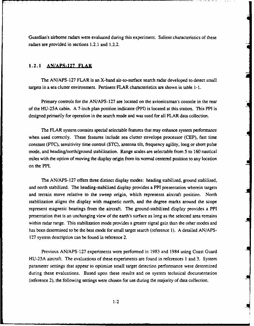
Previous AN/APS-127 experiments were performed in 1983 and 1984 using Coast GuardHU-25A aircraft. The evaluations of these experiments are found in references 1 and 3. System
parameter settings that appear to optimize small target detection performance were determined
during these evaluations. Based upon these results and on system technical documentation
(reference 2), the following settings were chosen for use during the majority of data collection.
1-2

L=
2 rnti
1-3-
RANGE: 10 nmi MODE: SEARCH
STAB: GND FTC: OFFFREQ: FIXED ANT. TILT: as required
PULSE: SHORT CEP: OFF
The AN/APS-127 system has an interface with the aircraft navigation computer to receiveinputs for stabilization and cursor position computation. The AN/APS-127 is not integrated intothe AN/ASD-6 AIREYE system, but can pass target positions to the AIREYE multipurpose display
and to the aircraft navigation computer.
1.2.2 AN/APS-131 SLAR
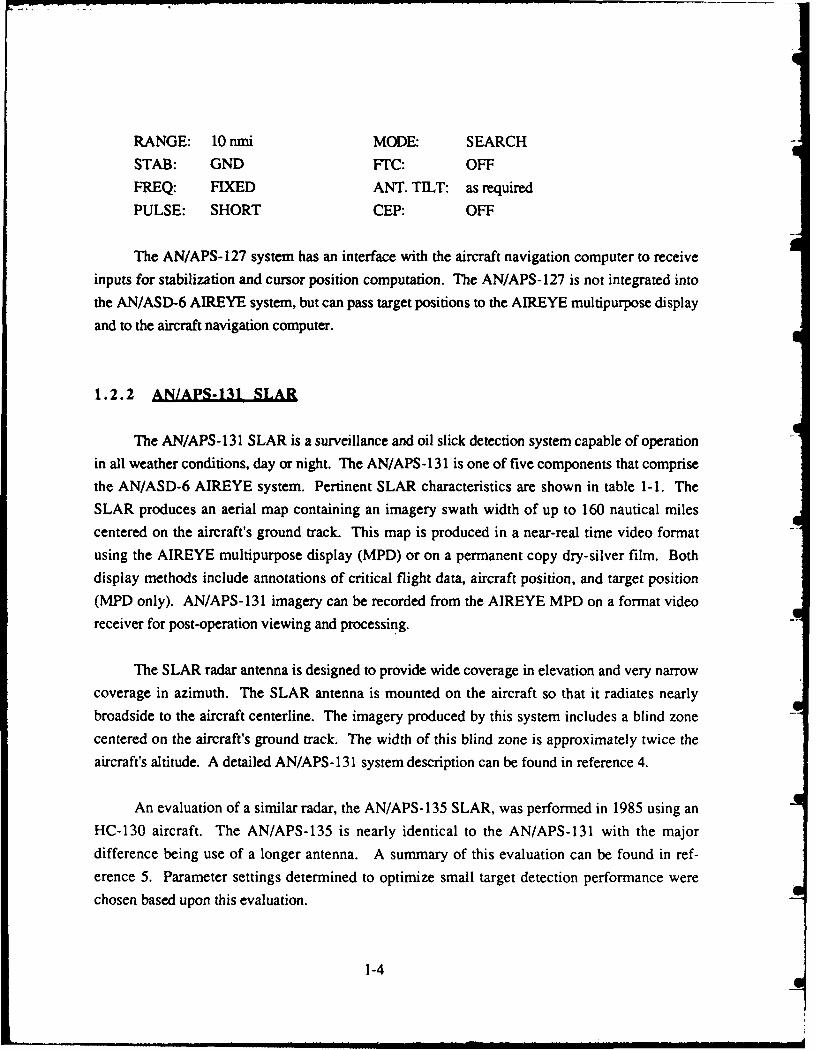
The AN/APS-131 SLAR is a surveillance and oil slick detection system capable of operationin all weather conditions, day or night. The AN/APS- 131 is one of five components that comprisethe AN/ASD-6 AIREYE system. Pertinent SLAR characteristics are shown in table 1-1. TheSLAR produces an aerial map containing an imagery swath width of up to 160 nautical milescentered on the aircraft's ground track. This map is produced in a near-real time video formatusing the AIREYE multipurpose display (MPD) or on a permanent copy dry-silver film. Bothdisplay methods include annotations of critical flight data, aircraft position, and target position(MPD only). AN/APS-131 imagery can be recorded from the AIREYE MPD on a format video
receiver for post-operation viewing and processing.
The SLAR radar antenna is designed to provide wide coverage in elevation and very narrowcoverage in azimuth. The SLAR antenna is mounted on the aircraft so that it radiates nearly
broadside to the aircraft centerline. The imagery produced by this system includes a blind zone
centered on the aircraft's ground track. The width of this blind zone is approximately twice theaircraft's altitude. A detailed AN/APS-131 system description can be found in reference 4.
An evaluation of a similar radar, the AN/APS-135 SLAR, was performed in 1985 using anHC-130 aircraft. The AN/APS-135 is nearly identical to the AN/APS-131 with the majordifference being use of a longer antenna. A summary of this evaluation can be found in ref-erence 5. Parameter settings determined to optimize small target detection performance were
chosen based upon this evaluation.
1-4

The following settings were used during the majority of SLAR data collection.
RANGE: 13.5 nmi (control panel) ANTENNA: BOTH
10 nmi (CDU menu) DISPLAY: NORMAL (CDU MENU)
DELAY: 0 (both sides) NAV: AUTO
PULSE RATE: AUTO STC: as required
1.3 EXPERIMENT DESCRIPTION
1.3.1 jcjgants
This evaluation was conducted and controlled by the R&D Center, Avery Point, Groton,
Connecticut. A field team consisting of five Coast Guard military and civilian personnel from theR&D Center and four contractor personnel performed on-site monitor, control, maintenance,
liaison, and data collection supervision functions.
The radar systems were installed on Coast Guard HU-25A aircraft No. 2118 assigned to
Coast Guard Air Station Miami, Florida. Air Station Miami flight crews operated the aircraft and
sensors. The normal crew complement included two aviators and four aircrew (two sensor
operators, and two visual scanners). Air Station Miami also provided valuable technical support in
keeping the aircraft and its sensors in operating condition. This support ensured that 90 percent of
the scheduled flight days were actually provided. Air Station Miami also provided videotape
copies of the SLAR imagery for later evaluation.
Florida Atlantic University (FAU) was contracted to provide the R/V Oceaneer as a work
platform/monitoring vessel. The Oceaneer was used for daily deployment of the three life raft
search targets, and was itself used as a search target.
Coast Guard Station Fort Pierce, Florida, provided logistics support including mooring
space, communications support, and use of messing facilities for the Coast Guard Auxiliary search
target vessel crews. The station provided use of station vessels as search targets when the
operational workload permitted. Station Fort Pierce also assisted with liaison between the R&D
Center field team and local Auxiliarists.
1-5

Coast Guard Aids to Navigation Team Miami, Florida, provided the buoy vessel CG 55106
and crew to deploy a miniature meteorological buoy.
The majority of the search object/radar target vessels were provided by members of the
Coast Guard Auxiliary (Seventh Coast Guard District, Auxiliary Division 5 East). The 7 vessels
were operated and crewed by 29 Auxiliarists, who volunteered their time, skill, and effort. Use of
the Coast Guard Auxiliary provided for target vessels of various sizes and types, at a substantially
lower cost than if all search target vessels had to be chartered.
Table 1-2 lists the aircraft and vessels resources used in conducting this experiment.
Table 1-2. Participating Aircraft and Vessels
SOURCE AIRCRAFT/VESSEL
Coast Guard Air Station Miami, CGNR 2118
Opa Locka, FL
Coast Guard Station Ft. Pierce CG 41341
Ft. Pierce, FL CG 252501
Coast Guard Auxiliary Sea Hawk (Facility No. 2167)
Seventh Coast Guard District, Gen Too III (Facility No. 6031)Auxiliary Division 5 East Vivant (Facility No. 9216)
Jade East (Facility No. 6117)Skippers II (Facility No. 6104)
Lady Irene (Facility No. 9204)Pete's Pride (Facility No. 6089)
Florida Atlantic University R/V Oceaneer
Boca Raton, FL
1-6
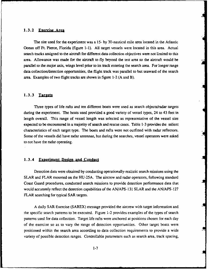
1.3.2 A
The site used for the experiment was a 15- by 30-nautical mile area located in the Atlantic
Ocean off Ft. Pierce, Florida (figure 1-1). All target vessels were located in this area. Actual
search tracks assigned to the aircraft for different data collection objectives were not limited to this
area. Allowance was made for the aircraft to fly beyond the test area so the aircraft would be
parallel to the major axis, wings level prior to its track entering the search area. For longer range
data collection/detection opportunities, the flight track was parallel to but seaward of the searcharea. Examples of two flight tracks are shown in figure 1-2 (A and B).
1.3.3 Tar~get
Three types of life rafts and ten different boats were used as search objects/radar targets
during the experiment. The boats used provided a good variety of vessel types, 24 to 43 feet in
length overall. This range of vessel length was selected as representative of the vessel size
expected to be encountered in a majority of search and rescue cases. Table 1-3 provides the salient
characteristics of each target type. The boats and rafts were not outfitted with radar reflectors.
Some of the vessels did have radar antennae, but during the searches, vessel operators were askedto not have the radar operating.
1.3.4 Exneriment Design and Conduct
Detection data were obtained by conducting operationally-realistic search missions using the
SLAR and FLAR mounted on the HU-25A. The aircrew and radar operators, following standardCoast Guard procedures, conducted search missions to provide detection performance data thatwould accurately reflect the detection capabilities of the AN/APS-131 S LAR and the AN/APS-127
FLAR searching for typical SAR targets.
A daily SAR Exercise (SAREX) message provided the aircrew with target information and
the specific search patterns to be executed. Figure 1-2 provides examples of the types of search
patterns used for data collection. Target life rafts were anchored at positions chosen for each day
of the exercise so as to vary the range of detection opportunities. Other target boats were
positioned within the search area according to data collection requirements to provide a widevariety of possible detection ranges. Controllable parameters such as search area, track spacing,
1-7

N.
N
... .......
............ RESPONDER 2
VERO CENTER OF AREAI BEACWI. LATITUDE as 2703LG'N
LONGITUDE m 80009.0'W.............................. MTS BASELINES,............................... ................................................................................
............ -4................................ :A......................................... ........................ AREA CENTER
ST. LUCIE::::::::::,I;: COUNTY
AIRPORT MAJOR AXIS 1600MMASTER
................... STATION* 7 Iliiil
................ ..............
q a z a
TOUARDSTATION
FORT PIERCE:'........................................................... ATLANTIC OCEAN...........................................................................................................................
MT Ni i 1 Hm iml:...........................................
............ .................................................................. ............................................... ................................................................................ RESPONDER 1..................... ...HN:':...................................... I N
............. =M;M:iiiM.............. HH................... ........ ........................................................ .... .. .......
MM: IHHUMM 4R "H: ............ ................................ ...........................
...........NH.
H..................
Figure I -1. Exercise Area
1-8

A. FLIGHTS WITHIN TARGET AREA
40
-~ SE
20:20 so 940 "90-I1460S CAPE KENNEM? to WE', WEST
S i~e: 1.9 Scaie: 25900~0 2916.48Z O'ct 97
B. FLIGHTS BEYOND TARGET AREA
40
SE
............ .... .. .....800?940 ?920 7
11460 CAPE K(ENNEDY to KEY WEST
Figure 1-2. Examples of Radar Search PatternsConducted by the HU-25A Aircraft
1-9

Table 1-3. Radar Target Vessel Descriptions
VESSEL NAME VESSEL DESCRIPTION PRINCIPAL DIMENSIONSMATERIAL lxwxh
(feet)
Life Raft 6-person Switlik w/canopy rubber/fabric 7.5 diameter3.75 height
Life Raft 10-person Switlik w/canopy rubber/fabric 10.5 x 7.5 x 5
Life Raft 10-person Goodrich w/canopy rubber/fabric 9.2 diameter5.25 height
Sea Hawk Spacecraft cuddy cabin fiberglass 24 x 8 x 6
Gen Too III Trojan express cruiser fiberglass 25 x 9.5 x 10
CG 252501 25-foot Coast Guard UTL fiberglass 25 x 8.2 x 6
Vivant Albin 27 trawler fiberglass 27 x 10 x 9
R/V Oceaneer Long Line trawler fiberglass 34 x 13 x 7.5
Jade East Sail Cutter fiberglass 37 x 12 x 9
Skippers II Pacemaker fly bridge sport fish fiberglass 38 x 14 x 9
Lady Irene Viking fly bridge sport fish fiberglass 38.3 x 13.9 x 15
CG 41341 41-foot Coast Guard UTB aluminum 41 x 13.5 x 13.2
Pete's Pride Albin fly bridge trawler fiberglass 43 x 14.5 x 12
1-10
altitude, and starting points were assigned to fulfill specific data collection objectives. Onboardobservers recorded essential data and coordinated unit activities with the aircrew and R&D Center
control personnel.
The on-scene environmental conditions were recorded by R&D Center personnel onboardthe RV Oceaneer. Environmental conditions were recorded hourly throughout the day or when theconditions changed significantly. Atmospheric and sea conditions were measured by sensors or byestimate as appropriate and recorded on an Environmental Conditions Summary (figure 1-3).
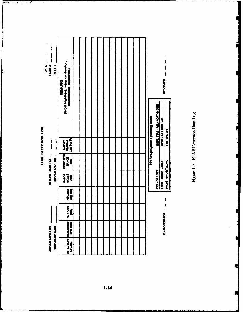
Each detection of a target by the SLAR was logged in real time by the operator on a SLARDetection Log (figure 1-4). Each SLAR detection log entry included detection time and targetlocation as well as radar and aircraft operating parameters. The detections for the FLAR wererelayed to an onboard R&D Center observer who logged the detection time, range, and bearing on
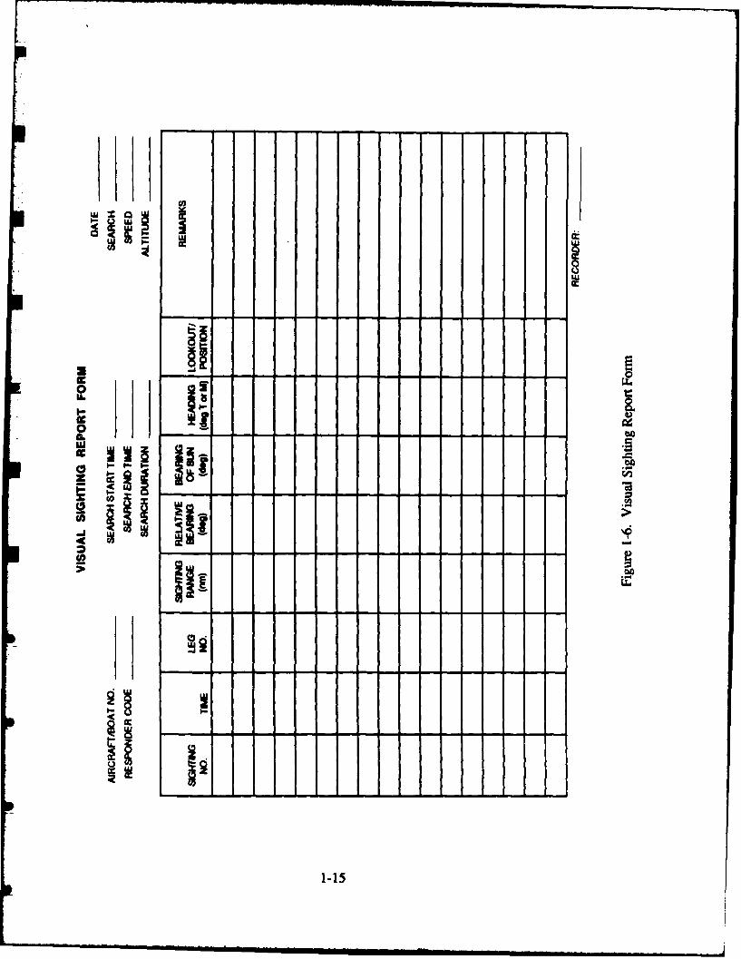
a FLAR Detection Log (figure 1-5). Aircraft and FLAR operating parameters were also recorded.Visual detections were also logged on a not-to-interfere basis for informational and backup
purposes on the Visual Sighting Report Form (figure 1-6). The visual data was not used in the
analysis. Each radar detection was verified during post-exercise analysis by comparing thereported detections with the locations of the target craft.
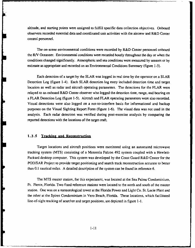
1.3.5 Tracking and Reconstruction
Target locations and aircraft positions were monitored using an automated microwave
tracking system (MTS) consisting of a Motorola Falcon 492 system coupled with a Hewlett-Packard desktop computer. This system was developed by the Coast Guard R&D Center for thePOD/SAR Project to provide target positioning and search track reconstruction accurate to better
than 0.1 nautical miles. A detailed description of the system can be found in reference 6.
The MTS master station, for this experiment, was located at the Sea Palms Condominium,Ft. Pierce, Florida. Two fixed reference stations were located to the north and south of the master
station. One was on a meteorological tower at the Florida Power and Light Co. St. Lucie Plant andthe other at the Spires Condominium in Vero Beach, Florida. These locations, which facilitated
line-of-sight tracking of searcher and target positions, are depicted in figure 1-1.
I-11

LU
LUU
I- L
i!I L
4c L
r ulU
i ccz30
-J _ _ - - 1
1-1

gillZ00
1i
UU
1-1
~L
I iu
ii I F
I- a
01-1

The trackline of the HU-25A often took it beyond the range of the MTS. When this
occurred, the position of the aircraft, as displayed on the onboard navigation computer, was used
to reconstruct the track. These positions were recorded once per minute while outside MTS
coverage and were recorded as a navigation tie-in two or three times on each search leg while
within MTS coverage. These positions were recorded on the Aircraft Position Log (figure 1-7).
During data reconstruction all aircraft positions were converted to the MTS coordinate base.
Target and aircraft (when within MTS range) positions were recorded continuously by the
computerized tracking system, displayed in real time on the CRT (as shown in figure 1-2), and
recorded on a microcomputer hard disk every 15 to 30 seconds.
Recorded target and aircraft position data were used to generate an 8- by 12-inch hard copy
plot of each search. Target locations were marked on these plots with letters. The aircraft tracks
were plotted with a '+' to designate every fifth position fix. A hard copy chronology of the search
and target craft positions was also generated to accompany the plot of each search. Using theseplots and the detection logs described in section 1.3.4, accurate lateral range measurements and
detection/miss determinations could be made. A target was considered an opportunity for detection
on any given search leg if the aircraft passed it within the selected radar range scale distance. If alogged target detection could be correlated with the target's position, it was considered a detection.
Otherwise, a miss was recorded for the target on that particular search leg. These detections and
misses, along with associated search parameters and environmental conditions, were compiled into
computer data files for analysis. These data files are listed in appendix A.
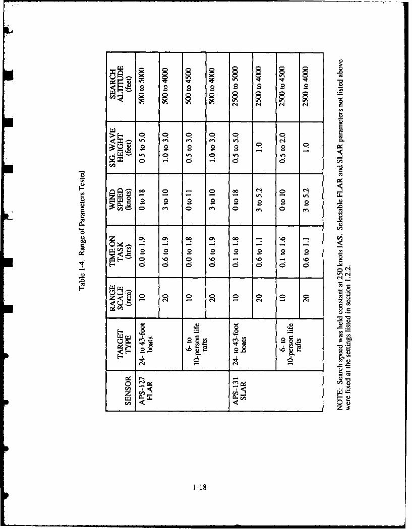
1.3.6 Range of Parameters Tested
The range of potentially-significant parameters tested for each sensor is shown in table 1-4.
The table includes controllable aircraft/sensor parameters (time on task, altitude, range scale),
environmental parameters expected to influence radar performance (wind speed and wave height),
and target type/size. Search speed was held constant at 250 knots indicated air speed (IAS) for all
data collection.
Although wind speeds ranged from 0 to 18 knots and wave heights ranged from 0.5 to 5
feet, it should be noted that the most severe of these conditions occurred on the first day of data
collection, June 8, when wave heights were 3 to 5 feet and winds were 12 to 18 knots. During the
1-16

.. m . U EE P I I U I i I
AIRCRAFT POSITION LOG
Aircraft No. Date _ _
Recorder Search No.
RNAV Inputs Used
TIME LATITUDE LONGITUDE SEARCH LEG(HH:MM:SS) (DD-MM.M) (DDD-MM.M)
I I-I
Figure 1-7. Aircraft Position Log
1-17
. .. 2 • 2
o'.7
a 9
o000 00
z O O
U
1-1
Cd 0 0
CA0
00Z~c o. a o A00 - '
CO ~ -. -~ ~ ~ - .--C 'n
2 co 2 2 2* ~ ~~~ it9~ 0 9 \O\
~ 0 0 0 010-18

remaining 7 days of data collection, significant wave heights ran 0.5 to 3 feet and winds were 0 to
11 knots.
Range scale and search altitude were the only selectable parameters varied during datacollection so that statistically significant sample sizes could be generated. Other sensor parameters
such as CEP, STC, FTC, and display stabilization were fixed at the settings listed in section 1.2 oroptimized by the radar operators as needed.
The only potentially-significant human factor investigated for its influence on detection
performance was time on task.
An additional "environmental" factor that must be considered in the data analysis is vessel
traffic density. Although exact vessel counts could not be made, it was obvious from both visualand radar observations that, on all days other than 8 June, vessel traffic was heavy to extremelyheavy in the search area. This traffic level may have reduced the radar operators' ability to detectmarginal-strength targets due to the high reporting/recording workload it imposed on them.
1.4 ANALYSIS APPROACH
1.4.1 Measure of Search Performance
The primary performance measure currently used by SAR mission coordinators to plan
searches is sweep width (W). Since this radar evaluation was intended to support improved CoastGuard SAR mission planning, W was chosen as the measure of radar search performance to be
developed during data analysis. Sweep width is a single-number summation of a more complexrange/detection probability relationship. Mathematicaly,
Sweep Width (W) = f P(x)dx,
where
x = lateral range or closest point of approach to targets of opportunity (seefigure 1-8), and
P(x) = probability of detection at lateral range x.
1-19

gTARGEfTim~mbmLATERAL RANGE
Figure 1-8. Definition of Lateral Range
Figure 1-9 shows a typical P(x) curve as a function of lateral range. In figure 1-9, (x) is thelateral range of detection opportunities.
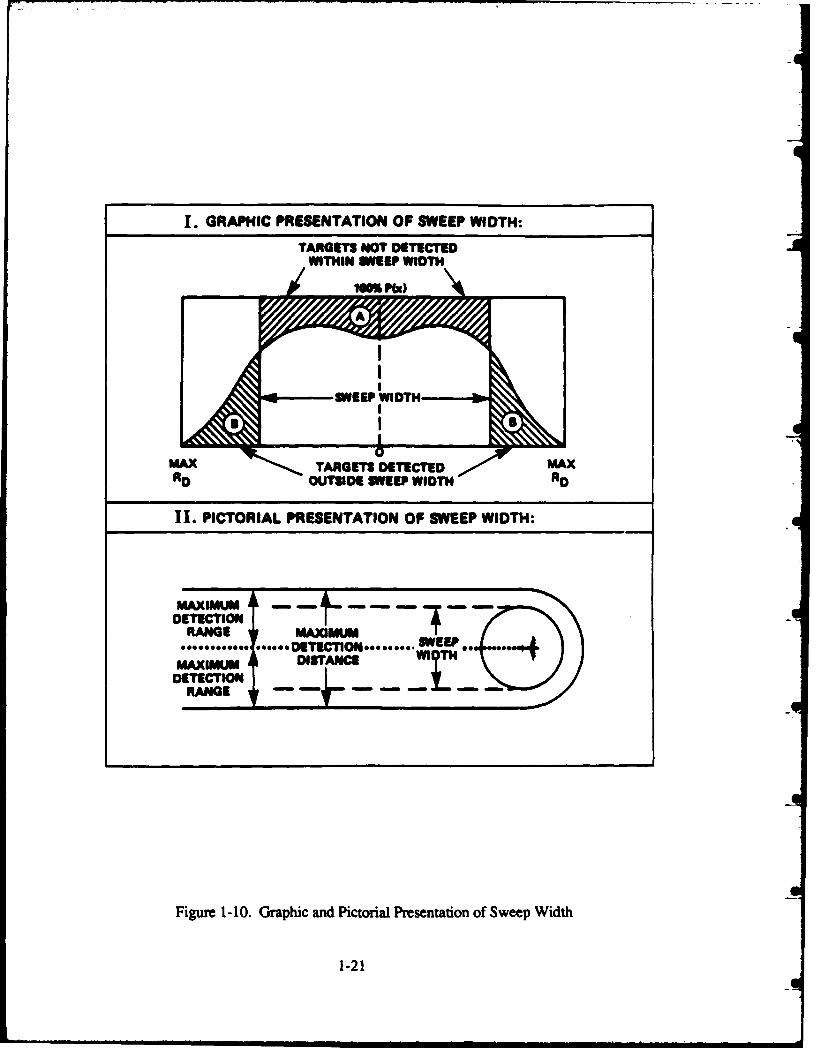
Conceptually, sweep width is the numerical value obtained by choosing a value of lateralrange less than the maximum detection distance for any given sweep so that scattered targets thatmay be detected beyond the limits of W are equal in number to those that may be missed withinthose limits. Figure 1-10 (I and I) illustrates this concept of sweep width. The number of targetsmissed inside the sweep width distance is indicated by the shaded portion near the top middle ofthe rectangle (area A); the number of targets sighted beyond the sweep width distance out tomaximum detection range (RD) is indicated by the shaded portion at each end of the rectangle
(areas B). Referring only to the shaded areas, when the number of targets missed equals thenumber of targets sighted (area A = sum of areas B), sweep width is defined. A detailedmathematical development and explanation of sweep width can be found in reference 7.
1.0'
TARGETS NOT SIGHTED
0o.5-IL ~T A RGETS ;81GH T 721
Om1011ER0.0*
LATERAL RANGE ()
K LATERAL HA -OF OEITION
Figure 1-9. Relationship of Targets Detected to Targets Not Detected
1-20
IGRAPHIC PRESENTATION OF SWEEP WIDTH:
TARGET NOT DETICTEDWITHIN SWEP WIDTH
OUSWDE EP WIDTH
HI. PICTORIAL PRESENTATION OF SWEEP WIDTH:
MAX IMUM - --
DETECTIONWITRANGE - -MU
Figure 1-10. Graphic and Pictorial Presentation of Sweep Width
1-21

1.4.2 Analysis of Search Data
Three primary questions were addressed in the analyses of FLAR and SLAR det.,ction data.
1. What target-, sensor-, platform-, and environment-related parameters exerted
significant influence on the detection performance of the two radars?
2. What are the FLAR and SLAR sweep width estimates for various combinations of
significant parameters identified during step 1?
3. What are the combined FLAR/SLAR sweep widths for various combinations of
significant parameters identified during step 1?
1.4.2.1 Development of Raw Data
During data reconstruction, detection and closest point of approach (CPA) ranges for each
target opportunity were determined by referring to logs kept by the observers and radar operators
onboard the search aircraft and to MTS-generated position/time plots for each search. When the
time, range, and relative bearing of a contact reported by the radar operators agreed with the MTS
plot, a target detection was recorded. Actual detection ranges were measured on the MTS plot
directly from the aircraft's trackline position at the time of contact to the target position. CPA
(lateral) ranges were measured from the target to the nearest point on the aircraft's trackline.
Similarly, any targets that passed within the selected FLAR or SLAR range scale limit and were not
detected were recorded as a "miss". This reconstruction procedure was applied to each radar
independently so that separate FLAR and SLAR data bases were developed. Each leg of a search
pattern was considered a new set of target detection opportunities.
The lateral range, environmental conditions, target type, time on task, and other search
parameters of interest were recorded along with the detection/miss indicator. A separate raw data
file was developed for each search day, which included all valid target detections and all misses
that met the above criterion. These data files were entered into a VAX 11/780 cnmputer for
analysis. Copies of these raw search data files are included in appendix A.
1-22

1.4.2.2 LOGODDS Multivariate Regression Model
The influence of interactions among the primary search parameters of interest was
investigated using a sophisticated binary, multivariate regression analysis technique (LOGODDS).
The linear logistic (LOGODDS) model was selected as an appropriate analysis tool for fitting
POD/SAR Project search data where the dependent variable is binary (i.e., detection/no detection).The LOGODDS model is useful in quantifying the relationship between independent variables (xi)
and a probability of interest, R (in this case the probability of detecting a target). The independentvariables (xi) can be continuous (e.g., range, wave height, wind speed) or binary (e.g., high/low
altitude, SRU type 0 or 1). The LOGODDS model has been used with great success in previous
POD/SAR Project visual search performance analyses. It was used in the FLAR/SLAR analysis
because of its proven analytical power to identify significant search parameters and to quantify their
influence on target detection probability. For reasons that will be explained shortly, the
LOGODDS model was not used to fit lateral range curves to most of the FLAR and SLAR
detection data.
The equation that the LOGODDS model uses for target detection probability is:
1R= 1 +e -
where:S= a0 +a 1 x 1 + a2 x2 + a3x3 ....
ai = constants (determined by computer program), and
xi = independent variable values.
The LOGODDS model has the following advantages over other candidate
models/techniques.
I. The model implicitly contains the assumption that 0 5 R < 1.0. A linear model does
not, unless the assumption is added to the model (and then computation can become
very difficult),
2. The model is analogous to normal-theory linear models; therefore, analysis of variance
and regression implications can be drawn from the model.
1-23
3. The model can be used to observe the effects of several independent or interactive
parameters that are continuous or discrete.
4. A regression technique is better than non-parametric hypothesis testing, which does
not yield quantitative relationships between the probability in question and the values
of independent variables.
The primary disadvantages of the LOGODDS model are:
1. For the basic models, the dependent variable (R) must be a monotonic function of the
independent variables. This limitation became significant during the FLAR/SLAR data
analysis because the lateral range versus target detection probability relationships
usually contained a maximum and were therefore not monotonic.
2. The computational effort is substantial, requiring use of computer resources at the
mini-mainframe level.
Appendix A of reference 8 provides a more detailed description of the LOGODDS model.
Variables (in addition to lateral range) included in the LOGODDS data analysis for this
experiment were those that had demonstrated a significant influence on AN/APS-127 FLAR and
AN/APS-135 SLAR search performance during previous experiments (references 1, 3, and 5).
Additional variables that might be expected to influence radar search performance were also
considered in the analysis. The variables evaluated were:
1. Wind speed
2. Significant wave height*
3. Search altitude
4. Range scale
5. Target type and size
6. Time on task
*Significant Wave Height is defined in reference 9 as the height an experienced observer will give
when visually estimating the height of waves at sea.
1-24
Controllable variables other than those listed above, (such as search speed and FLAR display
stabilization mode) were either held constant or adjusted as required by the sensor operators to
achieve optimum small-target detection performance. Such variables were not considered in the
data analysis.
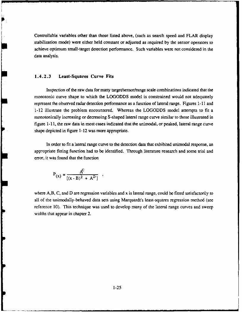
1.4.2.3 Least-Squares Curve Fits
Inspection of the raw data for many target/sensor/range scale combinations indicated that the
monotonic curve shape to which the LOGODDS model is constrained would not adequately
represent the observed radar detection performance as a function of lateral range. Figures 1-11 and
1-12 illustrate the problem encountered. Whereas the LOGODDS model attempts to fit a
monotonically increasing or decreasing S-shaped lateral range curve similar to those illustrated in
figure 1-11, the raw data in most cases indicated that the unimodal, or peaked, lateral range curve
shape depicted in figure 1-12 was more appropriate.
In order to fit a lateral range curve to the detection data that exhibited unimodal response, an
appropriate fitting function had to be identified. Through literature research and some trial and
error, it was found that the function
AcP(x) [(x-B)2 + AD]
where A,B, C, and D are regression variables and x is lateral range, could be fitted satisfactorily to
all of the unimodally-behaved data sets using Marquardt's least-squares regression method (see
reference 10). This technique was used to develop many of the lateral range curves and sweep
widths that appear in chapter 2.
1-25

LATERAL. RANGE
Figure I- 11. S-Shaped Curves
LATERAL RANGE
Figure 1-12. Unimodal Curve
1-26
*Although necessary to accommodate the unimodal curve shapes, the least-squares regressionmethod described above is a less satisfactory means of analyzing detection data than theLOGODDS regression method. Specifically, the least-squares method has the followinglimitations that LOGODDS does not.
1. The least-squares technique fits a function to a single, independent variable only(lateral range in this case), instead of to multiple parameters of interest. The effects of
other parameters cannot be identified or quantified.
2. The binary detection/miss data must be binned into lateral range intervals, each ofwhich should contain a reasonable number of detection opportunities, before being
input to the regression model.
3. The least-squares regression variables (A, B, C, and D) have no physical significancerelative to the detection process: they simply serve to adjust the fitting function'sresponse to the independent variable lateral range.
The limitations described above required that the detection data be pre-analyzed using theLOGODDS regression model to identify variables, other than lateral range, that exerted significantinfluence on target detection probability. This could be done because, even though detectionprobability demonstrated unimodal response to the lateral range parameter, a monotonic responsecould still be expected relative to other parameters such as search altitude, target type, and waveheight. Variables identified as significant during this LOGODDS pre-analysis were stratified intomeaningful levels to create data subsets that were, in turn, binned on lateral range. Finally, the x-ypairs of lateral range and target detection probability obtained in this manner were input to a
computerized, least-squares regression program along with reasonable starting estimates for theregression variables A, B, C, and D. Using this three-step process, lateral range curve functionswere developed for various combinations of sensor, range scale, target type, search altitude, and
environmental conditions.
1.4.2.4 Sweep Width Calculations
The lateral range curve functions obtained using the procedures described in sections
1.4.2.2 and 1.4.2.3 were integrated over appropriate radar range scale limits to obtain single-sensor sweep widths.
1-27
For FLAR sweep widths, the following procedures were used.
1. 10-nmi Ranje Scale. The applicable least-squares fitting function was integrated over
the limits 0 to ±10 nmi to obtain W.
2. 20-nmi Range Scale (boat targets). Since no data were collected at ranges less than 6
nmi, a multi-step process was used to estimate W as follows:
a. The lateral range curve was assumed to have the same general shape as it did on
the 10-nmi range scale.
b. An estimate of the lateral range curve "peak" location for the 20-nmi range scale
was obtained by determining the peak location as a percentage of range scale for
the 10-nmi range scale curve fits. This value was determined to be 34 percent,
which translates to 6.8 nmi for the 20-nmi range scale.
c. The target detection probability at 0 lateral range was estimated by assuming the
percentage drop from peak value was the same as for the 10-nmi range scale.
d. W was computed by integrating the applicable LOGODDS lateral range curve fit
over the limits ±6.8 to ±20 nmi (i.e., where data existed) and adding to this the
trapezoidal areas between lateral ranges 0 and ±6.8 nmi formed by the
extrapolation process described in steps a through c.
Data collected on the 20-nmi FLAR range scale indicated that life raft detection was negligible at
lateral ranges beyond 10 nmi and no sweep width estimate could be made.
For SLAR sweep widths, the following procedures were used.
1. 10-nmi Range Scale. The applicable least-squares or LOGODDS fitting function was
integrated over the limits ±0.8 to ±10 nmi. The SLAR blind zone was assumed to
extend ±0.8 nmi to both sides of the aircraft, which yields a conservative sweep width
estimate for altitudes of 2500 to 4500 feet.
2. 20-nmi Rane Scale. Insufficient data were collected for sweep width estimation.
1-28

Combined FLAR/SLAR sweep widths were estimated for the 10-nmi range scales by
combining the applicable lateral range curve functions as described below.
1 . The combined target detection probability PC assuming completely independent
sensors was computed at 0.1-nmi lateral range increments over the interval 0 to 10
nmi. The equation for this is:
Pc(independent) = 1- { [1 - P(FLAR)] [ I - P(SLAR)]).
2. The higher value of P(FLAR) and P(SLAR) was determined at each 0.1-nmi lateral
range increment. This represents the assumption of complete correlation between
sensors; that is, if the "weaker" sensor detects a particular target at lateral range x, the"stronger" sensor will also surely detect that same target at lateral range x. This higher
of two probabilities can be expressed as:
Pc(con'elated) = MAX [P(FLAR), P(SLAR]
for each lateral range increment.
3. Since the actual degree of correlation between the FLAR and SLAR sensors isindeterminate, a reasonable estimate of combined sensor target detection probability at
lateral range x is given by the "Vassel Average" (reference 11) of the two values
described above:
Pc (independent) + Pc (correlated)Pc(X) = _
2
After the combined FLAR/SLAR lateral range curves were obtained as described
above, combined-sensor sweep widths were obtained by numerical integration using
Simpson's Rule.
1-29
UE I I P E W I U I I I I I -
CHAPTER 2TEST RESULTS
2.1 INTRODUCTION
A total of 1,128 valid sensor-target interactions were reconstructed from the experiment.Data quantities are categorized by sensor, range scale, and target type in table 2-1. Data quantities
in table 2-1 pertaining to the 1O-nmi SLAR range scale reflect elimination of targets occurring
within the assumed O.8-nmi blind zone to either side of the aircraft.
Table 2- 1. Number of Searcher/Target Interactions
RADAR LIFE RAFT TARGETS BOAT TARGETS
SYSTEMCHAP1O--ni 20-nnii 1O-nmi 20-nmi
Dataquantities a Range Scale Range Scale Range Scale Range Scale
AN/APS- 127FLAR 224 59 412 120
AN/APS-131i SLAR 83 15 185 30
2-1
2.2 DETECTION PERFORMANCE
Sections 2.2.1 through 2.2.3 present results of the APS-127 FLAR, APS-131 SLAR, andcombined FLAR/SLAR analyses of detection performance. Lateral range curve fits and sweepwidth estimates are provided for each sensor/target/search parameter combination analyzed.
2.2.1 AN/APS-127 FLAR Detection Performance
2.2.1.1 FLAR Detection of Life Rafts
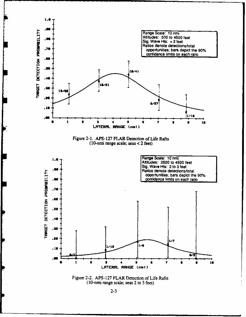
Figures 2-1 and 2-2 depict the raw detection data and least-squares fitted lateral range curvesfor FLAR detection of life rafts when the 10-nmi range scale was used. Significant wave height
was the only search variable in the data set that was found during LOGODDS regression analysisto exert significant influence on target detection probability. Figure 2-1 provides the lateral rangecurve for significant wave heights less than 2 feet, and figure 2-2 provides the lateral range curvefor 2- to 3-foot significant wave heights.
Inspection of the two lateral range curves indicates that detection performance against thesesmall targets degraded markedly with even a small increase in sea return. It should be noted thatonly a small data set was collected in the higher sea conditions, resulting in a rather uncertain lateralrange curve fit (the 90-percent confidence limits are extremely wide). Although the 500-footsearch altitude was not tested at the higher sea condition during this experiment, it is likely that theeffects of sea return would have been reduced had the lower altitude been used. Preliminaryresearch reported in reference 3 indicated that the APS-127 FLAR achieved marginal small target
detection capability in rough seas using 300- and 500-foot search altitudes, but was unable todetect the targets using a 1000-foot search altitude under the same conditions.
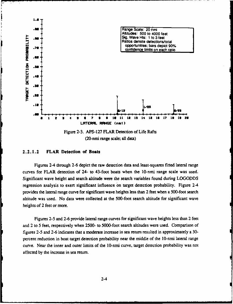
Figure 2-3 illustrates the raft detection performance achieved when using the 20-nmi rangescale of the APS- 127 FLAR. The data indicate negligible raft detection capability over the 9- to 20-nmi lateral range interval tested. No data were collected at lateral ranges less than 9 nmi because of
limitations on available experiment time. There is no reason to expect that the 20-nmi range scalewould have provided better life raft detection performance than the l0-nmi scale at lateral ranges
less than 9 nmi.
2-2
- IRange Scale: 10 nmiJAltitudes: 500 to 4500 feetSig. Wave Hts: c 2 feetRatios denote detections/total.76 iopportunities; bars depict the 90%
confidence limits on each ratio
w 19-141
.3
21 3 4 5 a 7• 1LTERIL RPME (nm )
Figure 2-1. APS-127 FLAR Detection of Life Rafts(1O-nmi range scale; seas < 2 feet)
.Range Scale: 10 nmiAttitudes: 2500 to 4500 feetSig. Wave Hts: 2 to 3 feet
.3 ]Ratios denote detections/totalopportunities; bars depict the 90%
- confidence limits on each ratio
.786
.18
AL~w1 2 3t I 4 3 4 7 4t m I
It LRTERRL RRIE (nmil)
Figure 2-2. APS-127 FLAR Detection of Life Rafts(10-nmi range scale; seas 2 to 3 feet)
2-3
| "| |
Loa
.. IRange Scale: 20 nmiAltitudes: 500 to 4000 feetSig. Wave Hts: I to 3 feetRatios denote detections/total
78. opportunities; bars depict 90%confidence limits on each ratio
.36
.,
a 1 2 3 4 a 6 7 1 9 t 11 1 3 I 14 13 19 17 11 11 21LLL. R.IE (nal)
Figure 2-3. APS-127 FLAR Detection of Life Rafts
(20-nmi range scale; all data)
2.2.1.2 FLAR Detection of Boats
Figures 2-4 through 2-6 depict the raw detection data and least-squares fitted lateral range
curves for FLAR detection of 24- to 43-foot boats when the 10-nmi range scale was used.
Significant wave height and search altitude were the search variables found during LOGODDS
regression analysis to exert significant influence on target detection probability. Figure 2-4
provides the lateral range curve for significant wave heights less than 2 feet when a 500-foot search
altitude was used. No data were collected at the 500-foot search altitude for significant wave
heights of 2 feet or more.
Figures 2-5 and 2-6 provide lateral range curves for significant wave heights less than 2 feet
and 2 to 5 feet, respectively when 2500- to 5000-foot search altitudes were used. Comparison of
figures 2-5 and 2-6 indicates that a moderate increase in sea return resulted in approximately a 30-
percent reduction in boat target detection probability near the middle of the 10-nmi lateral range
curve. Near the inner and outer limits of the 10-nmi curve, target detection probability was not
affected by the increase in sea return.
2-4

Range Scale: 10 nmi1.. Altitudes: 500 feet
Sig. Wave Hts: < 2 feetRatios denote detections/total
.3Is1/to opportunities; bars depict 90%21--wconfidence limits on each ratio
m -
Is-*.18
a 1 2 2 4 3 6 7a 5 1
LATERAL RAN'GECm(ml)
Figure 2-4. APS-127 FLAR Detection of 24- to 43-foot Boats(10-nmm range scale; seas < 2 feet; 500-foot altitude)
Range Scale: 10 nmiAltitude: 2500 to 5000 feetSig. Wave Hts: < 2 feet
-J .0 Ratios denote detections/totalopportunities; bars depict 90%
73 confidence limits on each ratio
.46-A 112
wtvs-
0-9-
.13n
LR'TERA RANGE (nml)
Figure 2-5. APS-127 FLAR Detection of 24- to 43-foot Boats(10-rni range scale; seas < 2 feet; 2500- to 5000-foot altitudes)
2-5

Range Scale: 10 nmiAltitudes: 2500 to 5000 feetSig. Wave Hts: 2 to 5 feet
1.8 IRatios denote detections/totalopportunities; bars depict 90%c confidence limits on each ratio
-J78-
0
W .483sm31
0.
W .3 .
I 2 3 4 5 a I 1
LRTERRL RRNGE (nal )
Figure 2-6. APS-127 FLAR Detection of 24- to 43-foot Boats
(10-nmi range scale; seas 2 to 5 feet; 2500- to 5000-foot altitude)
A possible explanation for the change in lateral range curve shape exhibited in figures 2-5
and 2-6 is illustrated in figure 2-7. When seas are relatively calm (less than 2 feet, for example),
sea return appears only within a mile or two of the aircraft on a properly adjusted PPI display.
This sea return, shown as a shaded area in figure 2-7, occurs because at close range the transmitted
radar signal strikes the ocean surface at near-normal angles of incidence, causing much of the
signal to be reflected back to the antenna. As range from the aircraft increases, the angles of
incidence become shallower and the transmitted signal is reflected away from the aircraft. As
ocean waves become steeper, more of the radar signal is reflected back to the antenna and sea
return is received over the entire display range. As the FLAR operator adjusts display thresholds
to reduce sea return, weaker targets may be lost. In addition to the sea return area that varies with
sea state and operator adjustments, a baffle area exists aft of the aircraft that is permanently blanked
by the fuselage. For the AN/APS-127 FLAR, this baffle area consists of a 120-degree sector
centered at 180-degrees relative bearing as shown in figure 2-7.
2-6

LAATERAL
RANGE
TARGETIAh.*TRACK A:
RANGEI
DISPLAY
FIue27M agtTaksRltvIoT/P- 7FA P ipa
2-7AF OSTO

The effects of sea return and baffling, plus the circular shape of the PPI display, combine
to create a great deal of variation in the time that a particular radar contact is visible to the operator.
In figure 2-7, target tracks A, B, and C illustrate the possibilities. Target track A illustrates that
even a strong target will be visible to the FLAR operator only briefly if it is passed at a lateral range
close to the FLAR range scale limit. This effect is due to the circular shape of the PPI display and
is independent of target strength. A similar situation exists for targets that are passed close-aboard
(target track B). In this case, the target is visible only until it becomes masked by sea return.
Weak targets will be more easily lost in sea return than strong targets. Aft of the aircraft, the target
cannot be redetected because it is in the baffle area. Finally, it can be seen that targets passed at
lateral ranges near the middle of the range scale, as illustrated by target track C, are exposed to the
operator for the longest possible time.
It is probable, then, that only the strongest radar targets were detected consistently near the
inner and outer limits of the 10-nmi FLAR range scale. These targets were probably not
susceptible to masking by light-to-moderate sea return, which would explain why target detectionprobabilities near 0 and 10 nmi remained unchanged from figure 2-5 (seas < 2 feet) to figure 2-6
(seas 2 to 5 feet). The FLAR operator probably noticed the strong targets during their brief
exposure even when many other radar contacts were present (a typical situation during the
experiment). Weaker radar targets were probably detected most frequently in seas less than 2 feet
at intermediate lateral ranges, where they received maximum exposure time on the FLAR display.
When significant wave height increased to 2 feet or more, the weaker targets were probably
eliminated even at intermediate lateral ranges, which would cause the flattened lateral range curve
shape depicted in figure 2-6.
Figures 2-8 and 2-9 depict the raw detection data and LOGODDS lateral range curve fits for
FLAR detection of 24- to 27-foot boats and 34- to 43-foot boats, respectively, when the 20-nmi
range scale is used. A nominal 2-foot significant wave height was assumed for both LOGODDS
curve fits. Significant wave height and boat size (24 to 27 feet versus 34 to 43 feet) were the
search variables found to exert significant influence on target detection probability duringLOGODDS regression analysis. Search altitude was not found to exert a significant influence on
target detection probability as it was when the 10-nmi FLAR range scale was used. Conversely,
boat size was found to be a significant parameter in this data set but was not identified as a
significant parameter in the 10-nmi range scale data set. Closer examination of the two data sets
reveals a likely explanation for this response.
2-8

Range Scale: 20 nmi.66 Altitude: 500 to 4000 feet
Sig.Wave Hs: I to 3feetRatios denote detections/total
* opportunities; bars depict 90%*78 confidence limits on each ratio
C3 .48-
.30--
.28-
2/19.16
I .I I I I I . . . . . V . . a6 12 3 4 5 1 7 1 1 1 11 It 13 1 14 13 16 17 to Is anLATERAL RANGE (nmi)
Figure 2-8. APS- 127 FLAR Detection of 24- to 27-foot Boats(20-nnii range scale; all wave heights and altitudes combined)
i~e Range Scale: 20 nmiAltitudes: 500 to 4000 feetSig. Wave Hts: I to 3 feetRatios denote detections/total
>- Opportunities; bars depict 90%i.. **conf idence- limits on each ratio
z
W .48-
26as
.16 /1
a 1 2 2 4 5 3 7 3 9 16 11 12 13 14 1s is 17 1S 13 26
LATERAL RANGE (,nmi)Figure 2-9. APS-127 FLAR Detection of 34- to 43-foot Boats
(20-nmi range scale; all wave heights and altitudes combined)
2-9
In the boat target/10-nmi range scale data base, 24- to 27-foot boats comprised only 10percent (42 of a total 412) of the detection opportunities. This may not have been sufficient for a
statistically significant difference in target detectability to be identified even if such a difference did,
in fact, exist. Similarly, in the boat target/20-nmi range scale data base, only about 6 percent (7 of
120) of the detection opportunities occurred at 500-foot search altitude. Again, this was probably
not sufficient for a statistically significant difference in detection performance to be identified even
if such a difference did, in fact, exist. Thus, it is likely that boat size and search altitude both have
a significant influence on FLAR sweep width, but the data set is not yet robust enough to quantify
this influence for both range scales.
Inspection of figures 2-8 and 2-9 also reveals that no data were collected using the 20-nmi
range scale for lateral ranges less than 6 nmi. Limited experiment time and resources dictated that
testing of the outer half of the 20-nmi range scale be emphasized. As described in section 1.4.2.4,
the remainder of the lateral range curve for the 20-nmi range scale was approximated to obtain
sweep widti values.
2.2.2 AN/APS-131 SLAR Detection Performance
2.2.2.1 SLAR Detection of Life Rafts
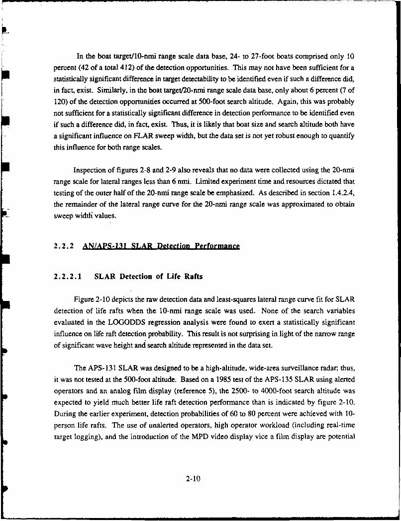
Figure 2-10 depicts the raw detection data and least-squares lateral range curve fit for SLAR
detection of life rafts when the 10-nmi range scale was used. None of the search variables
evaluated in the LOGODDS regression analysis were found to exert a statistically significant
influence on life raft detection probability. This result is not surprising in light of the narrow range
of significant wave height and search altitude represented in the data set.
The APS- 131 SLAR was designed to be a high-altitude, wide-area surveillance radar;, thus,
it was not tested at the 500-foot altitude. Based on a 1985 test of the APS-135 SLAR using alerted
operators and an analog film display (reference 5), the 2500- to 4000-foot search altitude was
expected to yield much better life raft detection performance than is indicated by figure 2-10.
During the earlier experiment, detection probabilities of 60 to 80 percent were achieved with 10-
person life rafts. The use of unalerted operators, high operator workload (including real-time
target logging), and the introduction of the MPD video display vice a film display are potential
L-10
1.9 Range Scale: 10 nmiAltitudes: 2500 to 4500 feetSig. Wave Hts: 0.5 to 2 feetRatios denote detections/total
opportunities; bars depict 90%confidence limits on each ratio
..
a.
law,~ .49
.131
8 1 a 2 4 s B 7 I 5 19LATERAL RANGE (nmi)
Figure 2-10. APS-131 SLAR Detection of Life Rafts(10-nmi range scale; all data)
factors in explaining this degradation in SLAR detection performance. Additional data collection
would be required to better identify the cause of the degraded detection performance and to
investigate the effect of using a 500-foot SLAR search altitude for small targets.
When the 20-nmi SLAR range scale was tested, none of the 15 life raft target opportunitieswere detected. While this is a small data set, it suggests that using the wider swath width is
ineffective for detecting small search objects such as life rafts.
2.2.2.2 SLAR Detection of Boats
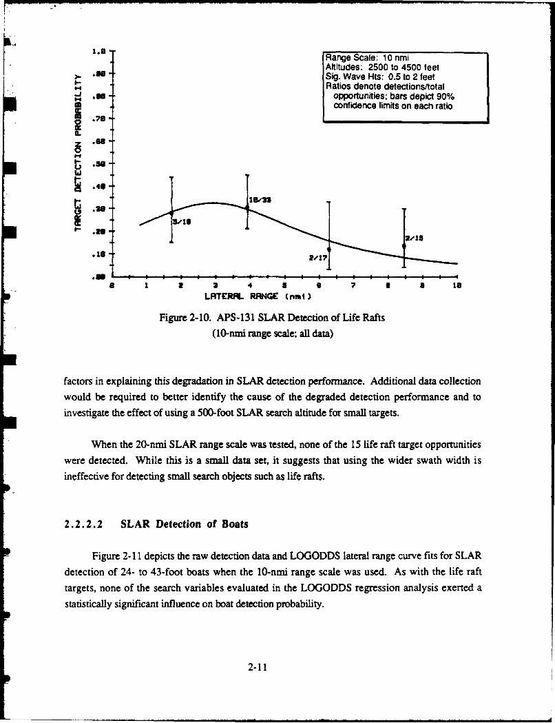
Figure 2-11 depicts the raw detection data and LOGODDS lateral range curve fits for SLAR
detection of 24- to 43-foot boats when the 10-nmi range scale was used. As with the life rafttargets, none of the search variables evaluated in the LOGODDS regression analysis exerted astatistically significant influence on boat detection probability.
2-11
Range Scale: 10 nmiAltitudes: 2500 to 5000 feetSig. Wave Hts: 0.5 to 5 feet
S.8 IRatios denote detections/totalopportunities; bars depict 90%
.36 [confidence limits on each ratio
I.ra
.4
*'2 44~.38.Vl4
o.58
2V4 .31.MOM
.3/6
3 3 4 5 6 7 I 1 18
LRTERRL RRNGE (nmt)
Figure 2-11. APS-131 SLAR Detection of 24- to 43-foot Boats
(10-nmi range scale; all data)
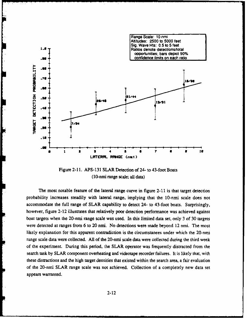
The most notable feature of the lateral range curve in figure 2-11 is that target detection
probability increases steadily with lateral range, implying that the 10-nmi scale does not
accommodate the full range of SLAR capability to detect 24- to 43-foot boats. Surprisingly,however, figure 2-12 illustrates that relatively poor detection performance was achieved against
boat targets when the 20-nmi range scale was used. In this limited data set, only 3 of 30 targets
were detected at ranges from 6 to 20 nmi. No detections were made beyond 12 nmi. The most
likely explanation for this apparent contradiction is the circumstances under which the 20-nmi
range scale data were collected. All of the 20-nmi scale data were collected during the third week
of the experiment. During this period, the SLAR operator was frequently distracted from the
search task by SLAR component overheating and videotape recorder failures. It is likely that, with
these distractions and the high target densities that existed within the search area, a fair evaluation
of the 20-nmi SLAR range scale was not achieved. Collection of a completely new data set
appears warranted.
2-12

a.. IRange Scale: 20 nmiAltitudes: 2500 to 4000 feet
.Sig. Wave Hts: 1 footRatios denote detections/total
opportunities; bars depict 90%confidence limits on each ratio
-68'@.
o11/
bE .43
.30
11 1,4
. . . . . . . . . . . . . . . . . .. V . I V . .:
3 1 2 3 4 5 B 7 I 3 13 11 1 12 14 15 16 17 11 1 t3LRTERAL RNGE (nml)
Figure 2-12. APS- 131 SLAR Detection of 24- to 43-foot Boats(20-nmi range scale; all data)
2.2.3 Combined FLAR/SLAR Detection Performance
To obtain combined sensor sweep widths, lateral range curves for the 10-nmi FLAR and
SLAR range scales were combined as described in section 1.4.2.4. Sufficient data were available
from both sensors to generate combined lateral range curves for raft and boat targets at low and
moderate significant wave heights (< 2 feet and 2 to 5 feet for boats; 2 to 3 feet for rafts) when
2500- to 5000-foot search altitudes were used. The four combined lateral range curves are shown
in figures 2-13 through 2-16.
The notch-shaped portions of the curves in figures 2-13 through 2-16 reflect the effect of the
SLAR blind zone. From 0 to 0.8 nmi, only the APS-127 FLAR was assumed to contribute to
target detection probability. The vertical beam pattern of the SLAR is such that its blind zone
extends to each side of the aircraft a distance approximately equal to the search altitude. Using a
0.8-nmi blind zone is equivalent to assuming a search altitude of approximately 4800 feet. This
value is a conservative representation of the blind zone limits for the data collected.
2-13

Range Scale: 10 nmiAltitudes: 2500 to 4500 feet
H emSig. Wave Hts: < 2 feet
tea.
*REM 13M(NI
Figure 2-13. Combined FLAR/SLAR Detection of Life Rafts(10-nmi range scale; seas < 2 feet; 2500- to 4500-foot search altutudes)
lo.6
on Range Scale: 10 nmiAltitudes: 2500 to 4500 feetSig. Wave Hts: 2 to 3 feet
3.73.74.
s..
2-14
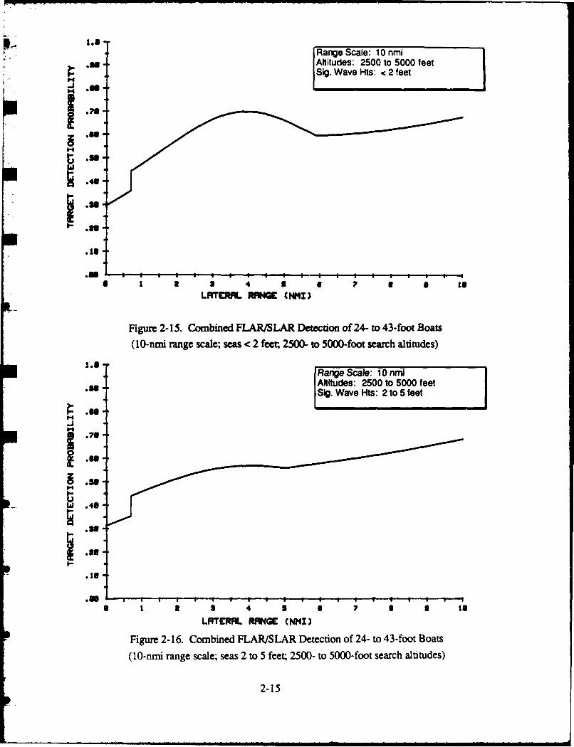
I... I..Range Scale: 10 nmi
Altitudes: 2500 to 5000 feet
Sig. Wave HtS: < 2 feetI
Jg
M
LRTERL RRNGE (NMI)
Figure 2-15. Combined FLAR/LAR Detection of 24- to 43-foot Boats
(1O-nini range scale; seas < 2 feet; 2500- to 5000-foot search altitudes)
Range Scale: 10 nmiAltitudes: 2500 to 5000 feetSig. Wave Hts: 2 to 5feet
.
..
a 3 4 5 a U 1
LATERA MAME (NMI)
Figure 2-16. Combined FLAR/SLAR Detection of 24- to 43-foot Boats
(10-nmi range scale; seas 2 to 5 feet; 2500- to 5000-foot search altitudes)
2-15
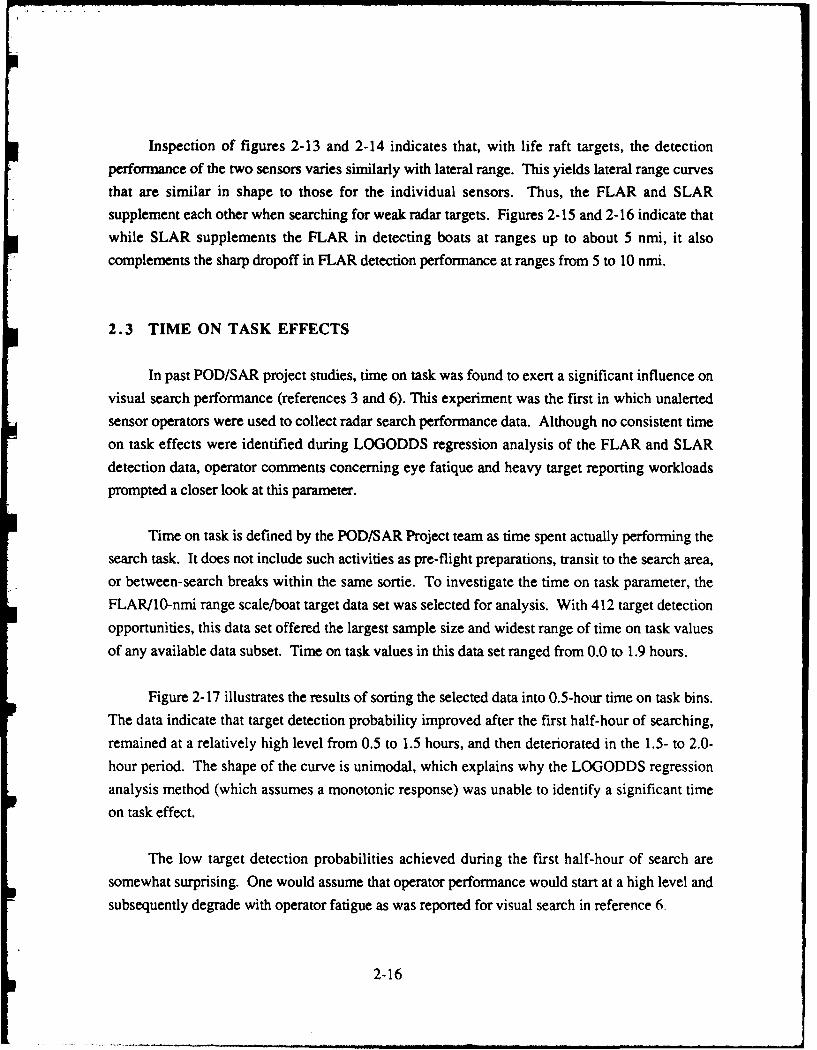
Inspection of figures 2-13 and 2-14 indicates that, with life raft targets, the detectionperformance of the two sensors varies similarly with lateral range. This yields lateral range curves
that are similar in shape to those for the individual sensors. Thus, the FLAR and SLARsupplement each other when searching for weak radar targets. Figures 2-15 and 2-16 indicate thatwhile SLAR supplements the FLAR in detecting boats at ranges up to about 5 nmi, it also
complements the sharp dropoff in FLAR detection performance at ranges from 5 to 10 nmi.
2.3 TIME ON TASK EFFECTS
In past POD/SAR project studies, time on task was found to exert a significant influence onvisual search performance (references 3 and 6). This experiment was the first in which unalerted
sensor operators were used to collect radar search performance data. Although no consistent time
on task effects were identified during LOGODDS regression analysis of the FLAR and SLARdetection data, operator comments concerning eye fatique and heavy target reporting workloads
prompted a closer look at this parameter.
Time on task is defined by the POD/SAR Project team as time spent actually performing the
search task. It does not include such activities as pre-flight preparations, transit to the search area,or between-search breaks within the same sortie. To investigate the time on task parameter, theFLAR/10-nmi range scale/boat target data set was selected for analysis. With 412 target detection
opportunities, this data set offered the largest sample size and widest range of time on task valuesof any available data subset. Time on task values in this data set ranged from 0.0 to 1.9 hours.
Figure 2-17 illustrates the results of sorting the selected data into 0.5-hour time on task bins.The data indicate that target detection probability improved after the first half-hour of searching,remained at a relatively high level from 0.5 to 1.5 hours, and then deteriorated in the 1.5- to 2.0-hour period. The shape of the curve is unimodal, which explains why the LOGODDS regression
analysis method (which assumes a monotonic response) was unable to identify a significant time
on task effect.
The low target detection probabilities achieved during the first half-hour of search are
somewhat surprising. One would assume that operator performance would start at a high level andsubsequently degrade with operator fatigue as was reported for visual search in reference 6.
2-16
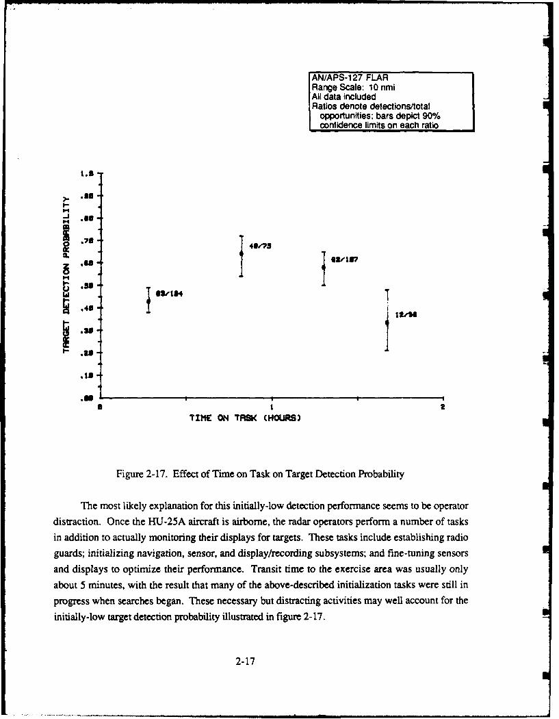
T . p. . U* * I I. • EU I I II
AN/APS-127 FLARRange Scale: 10 nmiAll data includedRatios denote detections/total
opportunities; bars depict 90%confidence limits on each ratio
1.1
.11
.78-47
~.g8
tin
TZIME ON "rRSK (HOURS)
Figure 2-17. Effect of Time on Task on Target Detection Probability
The most likely explanation for this initially-low detection performance seems to be operator
distraction. Once the HU-25A aircraft is airborne, the radar operators perform a number of tasks
in addition to actually monitoring their displays for targets. These tasks include establishing radio
guards; initializing navigation, sensor, and display/recording subsystems; and fine-tuning sensorsand displays to optimize their performance. Transit time to the exercise area was usually only
about 5 minutes, with the result that many of the above-described initialization tasks were still inprogress when searches began. These necessary but distracting activities may well account for theinitially-low target detection probability illustrated in figure 2-17.
2-17
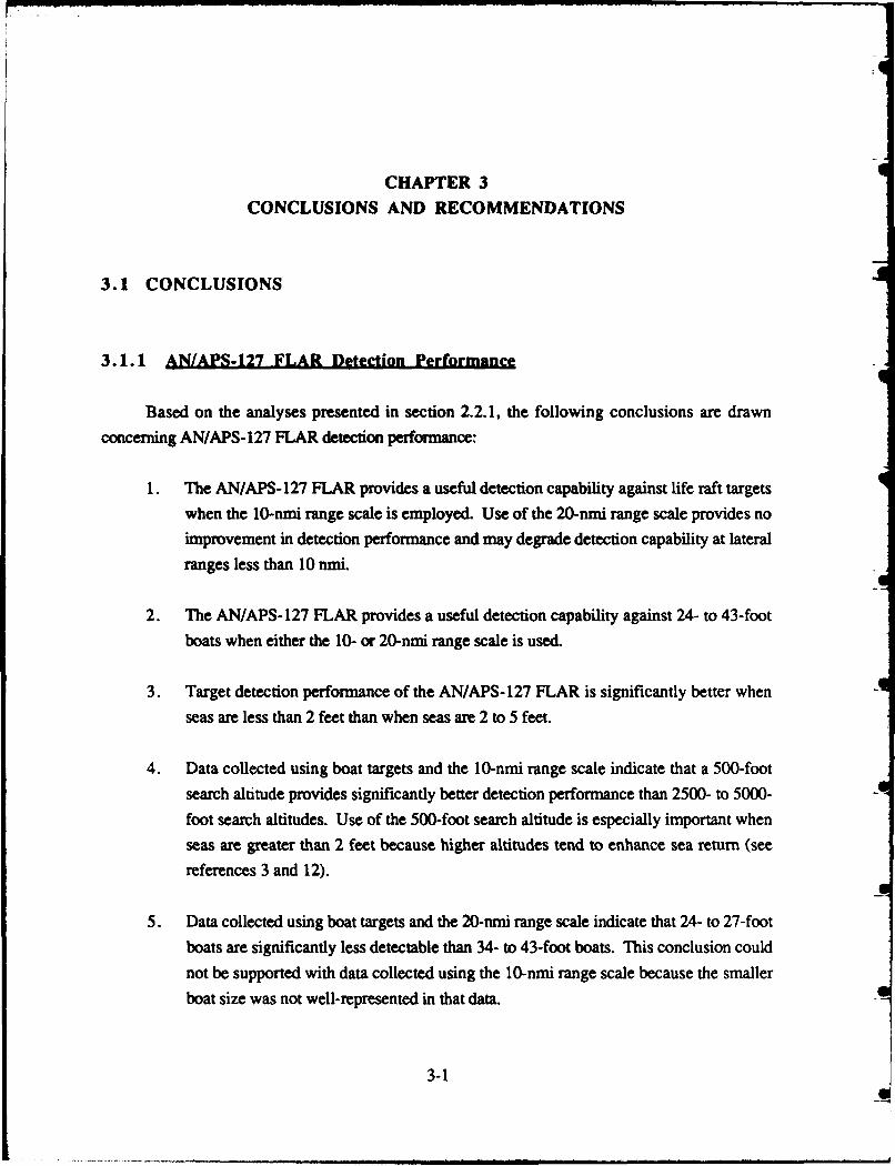
CHAPTER 3CONCLUSIONS AND RECOMMENDATIONS
3.1 CONCLUSIONS
3.1.1 AN/APS-127 FLAR Detection Performance
Based on the analyses presented in section 2.2.1, the following conclusions are drawnconcerning AN/APS-127 FLAR detection performance:
1. The AN/APS- 127 FLAR provides a useful detection capability against life raft targetswhen the 10-nmi range scale is employed. Use of the 20-nmi range scale provides no
improvement in detection performance and may degrade detection capability at lateral
ranges less than 10 nmi.
2. The AN/APS-127 FLAR provides a useful detection capability against 24- to 43-foot
boats when either the 10- or 20-nmi range scale is used.
3. Target detection performance of the AN/APS-127 FLAR is significantly better when
seas are less than 2 feet than when seas are 2 to 5 feet.
4. Data collected using boat targets and the 10-nmi range scale indicate that a 500-foot
search altitude provides significantly better detection performance than 2500- to 5000-foot search altitudes. Use of the 500-foot search altitude is especially important whenseas are greater than 2 feet because higher altitudes tend to enhance sea return (see
references 3 and 12).
5. Data collected using boat targets and the 20-nmi range scale indicate that 24- to 27-foot
boats are significantly less detectable than 34- to 43-foot boats. This conclusion could
not be supported with data collected using the 10-nmi range scale because the smallerboat size was not well-represented in that data.
3-1
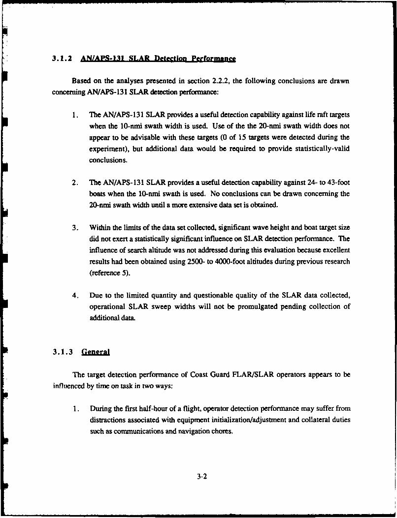
3.1.2 AN/APS-13I SLAR Deteetion Performanc
Based on the analyses presented in section 2.2.2, the following conclusions are drawn
concerning AN/APS-131 SLAR detection performance:
1. The AN/APS-131 SLAR provides a useful detection capability against life raft targets
when the 10-nmi swath width is used. Use of the the 20-nmi swath width does not
appear to be advisable with these targets (0 of 15 targets were detected during the
experiment), but additional data would be required to provide statistically-valid
conclusions.
2. The AN/APS-131 SLAR provides a useful detection capability against 24- to 43-foot
boats when the 10-nmi swath is used. No conclusions can be drawn concerning the
20-nmi swath width until a more extensive data set is obtained.
3. Within the limits of the data set collected, significant wave height and boat target size
did not exert a statistically significant influence on SLAR detection performance. The
influence of search altitude was not addressed during this evaluation because excellent
results had been obtained using 2500- to 4000-foot altitudes during previous research(reference 5).
4. Due to the limited quantity and questionable quality of the SLAR data collected,
operational SLAR sweep widths will not be promulgated pending collection of
additional data.
3.1.3 General
The target detection performance of Coast Guard FLAR/SLAR operators appears to be
influenced by time on task in two ways:
1. During the first half-hour of a flight, operator detection performance may suffer from
distractions associated with equipment initialization/adjustment and collateral duties
such as communications and navigation chores.
3-2

2. After approximately 1.5 hours of time on the search task, operator detection
performance appears to degrade due to psychological and/or physiological fatigue.
3.2 RECOMMENDATIONS
The following recommendations are made concerning HU-25A electronic search planning
and tactics based upon the results of analyses presented in chapter 2.
3.2.1 AN/APS-127 FLAR Searches
1. The sweep widths provided in table 3-1 should be used by Coast Guard search
planners to represent the FLAR search performance of HU-25A aircraft. These sweep
width values may represent a lower bound on operational values because of the intense
target reporting workload experienced during the experiment. However, the 5.4-nmi
life raft sweep width obtained for seas less than 2 feet during this experiment compares
favorably with the 5-nmi sweep width estimate provided in reference 13. The latter
estimate was computed from data that were collected using alerted FLAR operators
who had few extraneous targets to contend with. Thus, the sweep width values intable 3-1 should be considered accurate unless shown to be too conservative by future
data collection.
2. AN/APS-127 operators should keep the sweep origin near the bottom of the PPI
display when searching in the preferred Ground Stabilized mode. This practice willmaximize exposure time for targets that pass close aboard.
3. When target echoes are difficult to distinguish from sea return, AN/APS- 127 searchesshould be conducted at the lowest altitude consistent with safety of flight operations.When higher search altitudes must be used due to weather, air traffic, or the operatingrequirements of other onboard sensors/systems, degraded sweep width estimates
should be used where available.
3-3
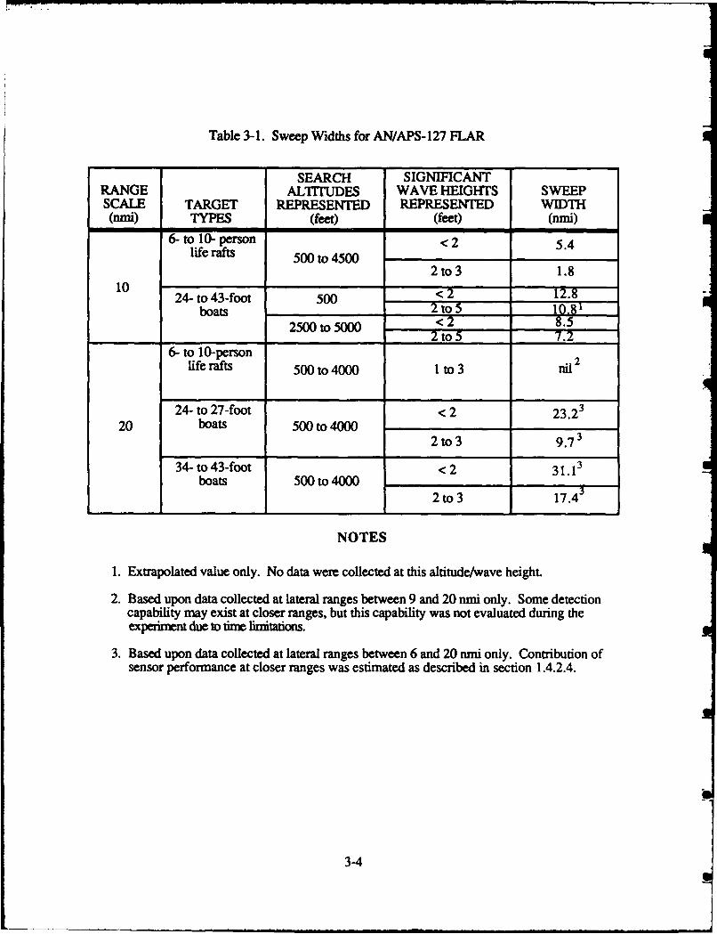
Table 3-1. Sweep Widths for AN/APS-127 FLAR
SEARCH SIGNIFICANTRANGE ALTITUDES WAVE HEIGHTS SWEEPSCALE TARGET REPRESENTED REPRESENTED WIDTH(nmi) TYPES (feet) (feet) (nmi)
6- to 10-person <2 5.4life rafts 500 to 4500
2to3 1.810 24- to 43-foot 500 <2 12.8
boats 2 tot5 500AI2500 to 5000 <2 8-5
2 to 5 7.2
6- to 10-person 2life rafts 500 to 4000 1 to 3 nil
24- to 27-foot <2 23.2320 boats 500 to 4000
2to3 9.73
34- to 43-foot <2 31.1 3boats 500 to 4000
2 to 3 17.4 3
NOTES
1. Extrapolated value only. No data were collected at this altitude/wave height.
2. Based upon data collected at lateral ranges between 9 and 20 nmi only. Some detectioncapability may exist at closer ranges, but this capability was not evaluated during theexperiment due to time limitations.
3. Based upon data collected at lateral ranges between 6 and 20 nmi only. Contribution ofsensor performance at closer ranges was estimated as described in section 1.4.2.4.
3-4
3.2.2 AN/APS-131 SLAR Searches
1. Based on analyses presented in reference 5, 2500- to 4000-foot search altitudes
should be used in lieu of an 8000-foot search altitude when searching for life rafts or
24- to 43-foot boats with the AN/APS-131 SLAR.2. The SLAR overheating problems experienced during this evaluation should be
investigated and alleviated, if possible, to improve sensor reliability.
3.2.3 Combined FLAR/SLAR Searches
1. When both sensor operators are FLAR- and SLAR-qualified, they should consider
exchanging positions near the midpoint of a search sortie. This practice might serve todiminish the operator performance degradation experienced after approximately 1.5hours' time on task.
3.2.4 General Recommendations
1. Sufficient time should be provided prior to commencing search for electronic sensoroperators to initialize and adjust their equipment. Collateral operator duties other thanthe search task should also be completed prior to commencing search. These tasks canusually be completed while en route to the search area, but extra lead time may berequired when short transits are involved.
3.2.5 Recommendations for Future Research
1. Additional data should be collected using the 20-nmi range scale of the AN/APS-127
FLAR against 20- to 45-foot boat targets. Special emphasis should be placed on
obtaining some of the detection opportunities at lateral ranges less than 10 nmi.
2. Additional data should be collected using the 20-nmi swath width of the AN/APS-131
SLAR against 20- to 45-foot boats and life rafts.
3-5

3. Additional data should be collected using the 10-nmi range scale of the AN/APS-127
FLAR against raft and boat targets. Specifically, the 500-foot search altitude should
be evaluated in 2- to 5-foot seas.
4. The FLAR and SLAR sensors should be further evaluated against boats in seas greater
than 4 feet.
5. The detection performance of longer SLAR range scales should be investigated against
appropriate SAR targets when resources become available.
3-6
:
- i Ii

REFERENCES
1. Ketchen, H. G.; St. Martin, J.; Hover, G. L.; and Mazour, T. J., Evaluation of U.S.
Coast Guard Forward-Looking Airborne Radars, Report No. CG-D-17-84, U.S.Coast Guard Research and Development Center and Analysis & Technology, Inc.,
March 1984.
2. USCG, C.G.T.O. 1U-25A-1, (Operator's Manual for HU-25A RNAV and AN/APS-127 Radar), (date unknown).
3. Ketchen, H. G.; Nash, L.; and Hover, G. L., Analysis of U.S. Coast Guard HU-25AVisual and Radar Detection Performance, Report No. CG-D-29-83, U.S. Coast GuardResearch and Development Center and Analysis & Technology, Inc., June 1983.
4. USCG, T.O. 12P3-7APS131-2, (Operator's Manual for AN/APS-131 SLAR), (dateunknown).
5. Robe, R. Q.; Edwards, N. C. Jr.; Murphy, D. L.; Thayer, N.; Hover, G. L.; Kop,M. E., Evaluation of Surface Craft and Ice Target Detection Performance by theAN/APS-135 Side-Looking Airborne Radar (SLAR), Report No. CG-D-30-86, U.S.Coast Guard Research and Development Center, International Ice Patrol, and Analysis& Technology, Inc., December 1985.
6. Edwards, N. C.; Osmer, S. R.; Mazour, T. J.; and Hover, G. L., Factors AffectingCoast Guard SAR Unit Visual Detection Performance, Report No. CG-D-09-82,U.S. Coast Guard Research and Development Center and Analysis & Technology,Inc., August 1981.
7. Koopman, B. 0., Search and Screening General Principles with HistoricalApplications, Pergamon Press (1980).
R-1
8. Edwards, N. C.; Osmer, S. R.; Mazour, T. J.; and Bouthilette, D. B., Analysis ofVisual Detection Performance (Fall 1978 Exlgriment), Report No. CG-D-03-79, U.S.
Coast Guard Research and Development Center and Analysis & Technology, Inc.,
December 1978.
9. Sorensen, R. M., Basic Coastal Engineering, J. Wiley & Sons, New York (1978).
10. Plot 50 Statistics, Volume 3, Tektronics, Inc. (1976).
11. Rollins, C. R., "A Cumulative Detection Probability Method (U)," 28th NavySymposium on Underwater Acoustics, Vol. I, November 1970, pp 121-133
(CONFIDENTIAL).
12. Kessler, 0. and Swyers, S. R., AN/APS-127 Airborne Radar System Evaluation,NADC Report Report No. 77283-20, Naval Air Development Center, 30 September
1977.
13. Hover, G. L. and Mazour, T. J., Guide for Visual and Electronic Search, Analysis &Technology, Inc. for U.S. Coast Guard Research and Development Center, August
1985.
R-2
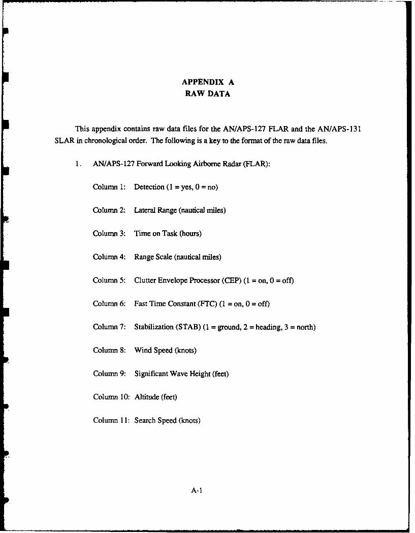
APPENDIX ARAW DATA
This appendix contains raw data files for the AN/APS-127 FLAR and the AN/APS-131SLAR in chronological order. The following is a key to the format of the raw data files.
1. AN/APS-127 Forward Looking Airborne Radar (FLAR):
Column 1: Detection (1 = yes, 0 = no)
Column 2: Lateral Range (nautical miles)
Column 3: Time on Task (hours)
Column 4: Range Scale (nautical miles)
Column 5: Clutter Envelope Processor (CEP) (1 = on, 0= off)
Column 6: Fast Time Constant (FTC) (1 = on, 0 = off)
Column 7: Stabilization (STAB) (1 = ground, 2 heading, 3 = north)
Column 8: Wind Speed (knots)
Column 9: Significant Wave Height (feet)
Column 10: Altitude (feet)
Column 11: Search Speed (knots)
A-1
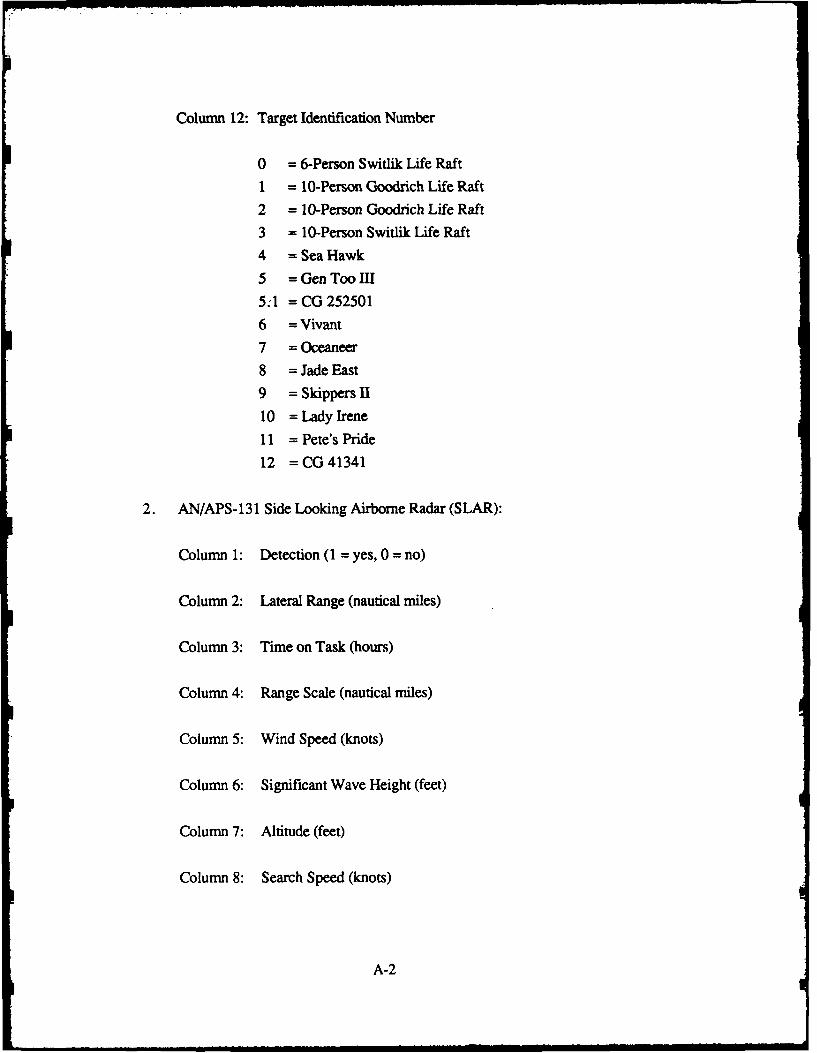
Column 12: Target Identification Number
0 = 6-Person Switlik Life Raft
I = 10-Person Goodrich Life Raft
2 = 10-Person Goodrich Life Raft
3 = 10-Person Switlik Life Raft
4 = Sea Hawk
5 = Gen Too III5:1 = CG 252501
6 = Vivant
7 = Oceaneer
8 = Jade East9 = Skippers U
10 = Lady Irene
11 = Pete's Pride
12 =CG 41341
2. AN/APS-131 Side Looking Airborne Radar (SLAR):
Column 1: Detection (1 = yes, 0 = no)
Column 2: Lateral Range (nautical miles)
Column 3: Time on Task (hours)
Column 4: Range Scale (nautical miles)
Column 5: Wind Speed (knots)
Column 6: Significant Wave Height (feet)
Column 7: Altitude (feet)
Column 8: Search Speed (knots)
A-2
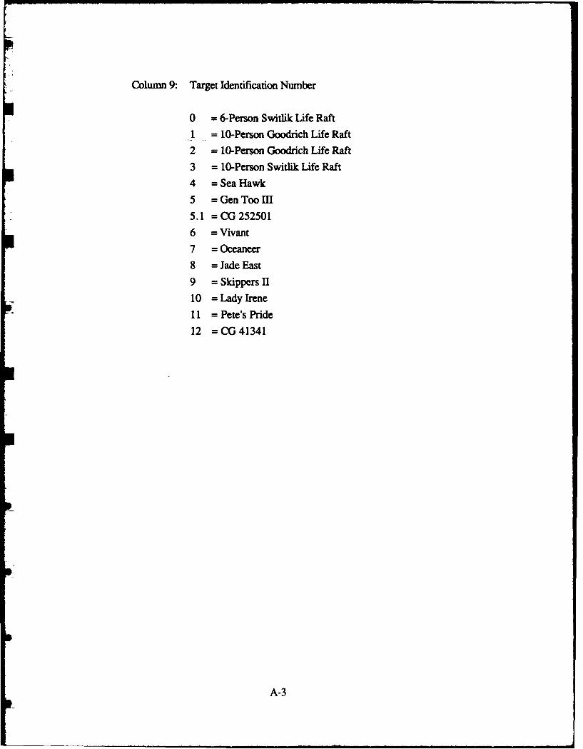
Column 9: Target Identification Number
0 = 6-Person Switlik Life Raft
1 = 10-Person Goodrich Life Raft2 = 10-Person Goodrich Life Raft3 = 10-Person Switlik Life Raft
4 = Sea Hawk
5 = Gen Too llI
5.1 = CG 252501
6 = Vivant7 = Oceaneer
8 = Jade East9 = Skippers H
10 = Lady Irene11 = Pete's Pride
12 =CG 41341
A-3
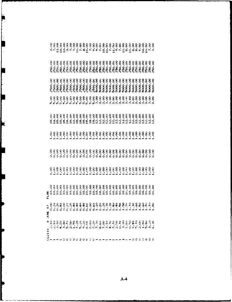
" '- -- -% ," -
C; ,Z Q• ,Z Y, CO, - , ;, .O 0 , o ,
, . N , r , i 0 C C4 r N 9 N N N N N 4 N N 4 N N N N N N N N
0-0 w .5000:00O:*
i,x
-~~~ .... :o. . .-.-.-.-.-.-.-.-.-----------
z
-...,,,- , ...-- - - - -
A-4
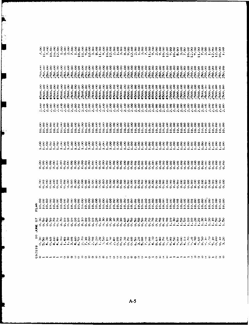
3 5 5 5 . 5. 55o., 5 11 0i 0-
. ... .. .. ... .. .. . . .. .. . ,...- o - ,V -TN0 1 N,4 - N ty - - OD M f, o- . P
0 8, : ,:,x 0^0 , 390.2-D 2 20 oo 2, o.2 ,'8
A" .". .' ,' , ,, .- 55 A- 0 5.-,. 55 . ._ 5 ,5 , .5 5 0,5,0000000 .5,
4 . ...... . ,-. , . .
.r Ir in I. o U lo. 6, D i8 V); o ':]Anl r I 1 i pV o I
>4 4 N>4P 4 J 4 ' N'N 4 N~N'N ' N N 4 NN N'N'N ' 'NP4N ' ' N N 'N N N N N N4 N 'N N N 'N N N N 1 '4.'N4 N N
. . . .. . . . . . . . .. . . . . . . .
XsC'ooojoo oo - C.-
. . .F . . . . . ...
.. . .. .
oo~~~~~~~o:oo_ .'-o 00 0 00 0 0 C.0 0 0 0o 0 0 0 O~O O OO: OQ:.
- - - - ------------- 2''fl~ O . 2 22 2 -------- r~ ' k
o o 3 00 z 00 0 :0 0 00 .0000 :' :Q . 1 i :3 s*25 C Q*..'- Ca
-0c0:2o0*-...2 ooo o o-o-c00 -00000S08 - So,
0 0 o0 o 0c 00

P. ' I'NO 0 ,r 1 'I '"01 N N 'N r4 P4414 N N r N J N NN NO r4r'n4 IN i4 N 4 r4 r- in N C04 n NO f4 r, r4 *4 NO r4 q 1 1 q
-N or !-,I4 O 0 ,
8 s88888
E BSS:*3 t EE 88*,88 882"*12 BE
~ ~*70
--- * F 8 8 i .8 S =-13 S~:: ioo:: -i B S 8 iss
-i * l l .' C ll ll lCl 6l l6- 1llw Clllll l
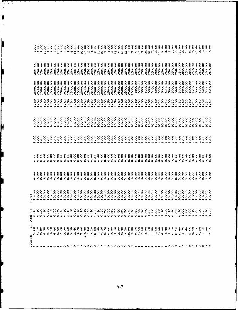
-Z - 7-
. . . . . .4 .4 .~ . . . . .4 . .N N . . . . . . . . .N . . . . .N .N .N N . . . . .
**4 N N NN NN NN N N N N N N N N N N 'N N N N NNN N
~C s
o0 Sz 0 0 C o0 00000 0000000000 0000 00 000 ^ Soo :c .. 00
~ ~: .: ~ 0 0=600 50oo000 o o w o 0 .o , 4 .4 oo oc, -5oo.o o o o oo o.:~*.55.
----------------------------------------------------
N0Q .:0.:00000000000000000-. 0 o C.
woo ooooczo ooo co o:O oc cooo. . .. .. .. .-
o- .C c6-5o 0m . 00o-,C 6o.0i. Doooo01 8o oC .o -* 0-
: Os~~~~~ ZOO.,.......* -0 c .2 0 0S 0 -I- 2 082
-0C,00 0 00 0 o0A-0A7Dz
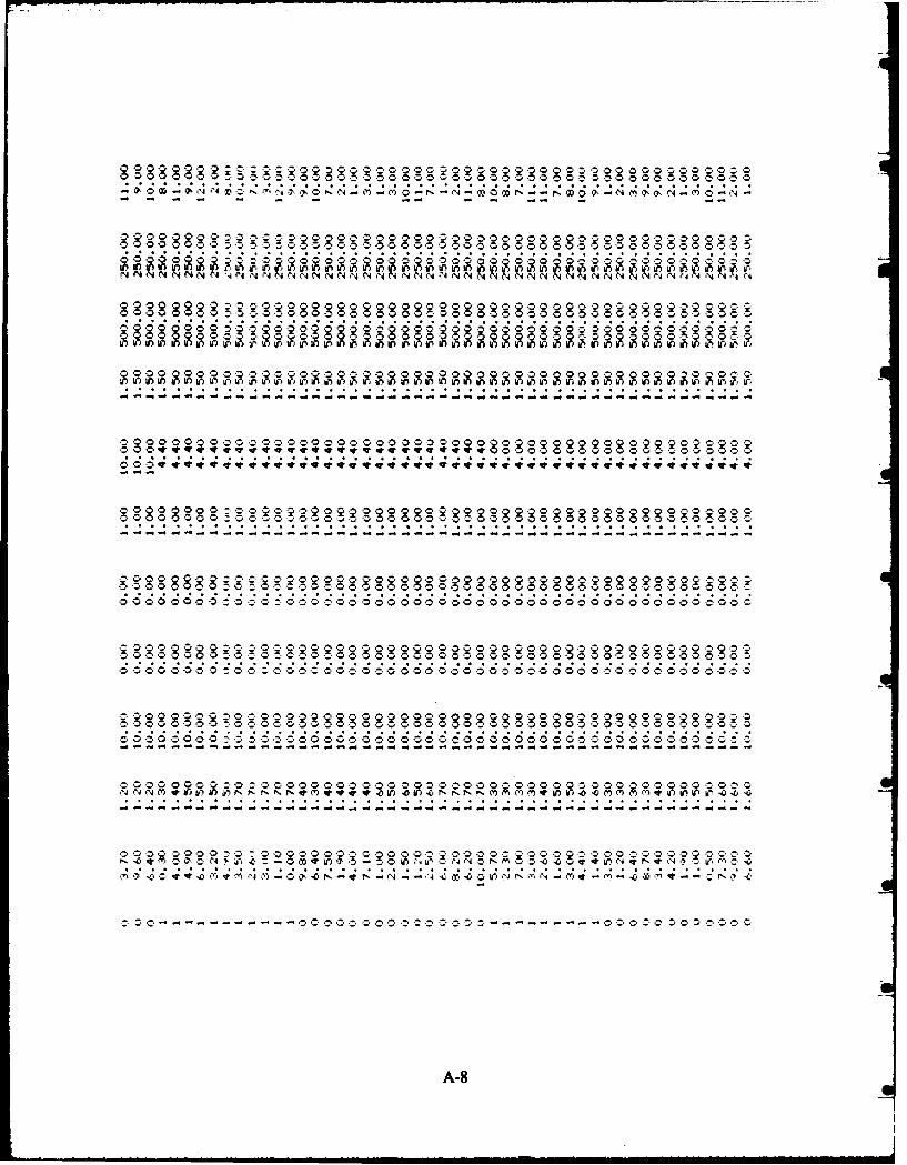
0~~~ - - 0 0 0 00 oto )D o0 .7- o *o 0 o:
2. C., :.. o0.o o o o c;0 osc.o. 0. 8 00
000 o 0 *0ooooo 3 02 80 008 o .050
o o0o o '0~ 00 0020000 0000 0
500 o O .5.:.ooooooo.oooooooooJ~ w0 000. -- ,o oo
0-0:0 oo o o o oo o o o o oo o o:
,5o.5880000 000C.o,00
C. ., , os C ooA-oo8
- - - -.. w w 0 0 0 00 50A- A- 5 5
o.,-OOo.o Og o20 0-.
i nw in on v it) to v if)i in U7 to 18in i0 0* 0n 0' 0* 0, 0' n Ifn Un in to in 0n in 0n i 0n 0n 0n 0n 0n in 0n 0n 0n 0n (7. 0'1 N N N N N N N N N N N N N N N N N N N N N N N N (1 N N N N N N N 0N N N N N N N N N N N N N N N N N N N N N'
0000oo oo 00 o0'o 0 Q, 0 0 0 0 0200 0 .0 0.3 8 0..*
.inniin inniinni 0 o2 7
Q00000000~ 00 0000~~0 ~0j00
~~~.~ 0 -.0 0) C. 0. Cs ~ ~., ~~ ' 0 0'1 -0 0 0 -,.0 w000 0 C. 0 C00 00 '00 C0.00 .0 5 0'0 1.7, z
o~oDo 0000880888008 000000 woo 00000 OOC0.:.0 R3
o o 0 0 0:oo o-ooc o o .**.0,-
ooo~~~-0 -C o ooo--Qoooooc0000-
* --------- - - - * 00-0-00-0-0-0-0-0-0-0-
0 0 *~0 0 0 ,
-- 0 0z0 -0 0 0 0 -0 0 0 0 0 0 0 0 0ooo:
-- 0 0; ON.*---K-0V00- Omo:ON -0 :000o000c0:0::00Z:C
A-9

50050-00 .750000-
- 0 - 0- 0 N N 0 -N ' 0 0 Ow N i NNt ', 0 -
oool~tj o:*o-000oooroolooooo 0 oo 01 on0 0 0 0 0
N-1 N "A 'N fN -1N.%N N N N N N-'4 N N N N N N N N N 'N N N N N N N N N N N N N N N N N N N 'N N N N N N N N N N
000000OO 000 00j 0 2 000
-D:0~ocoo~oo 00 00000 000000 0000
*:: O 0000 oo 00 O wo 0000w0000 00CO0000 000 000 000 000 Q 0
N~~~ 44 4 N N' N N NNN4,NNN N, N, N 000 000000 00 0 0 0 0 0 0 0 00 0 00 0 0~*
0=0 0 - , 0000 0 O 0 O o 0
C.00 00 00 00 000 0 00 0 00 0 00 0 0 00 0 0 0 00 0 00 0 00 0 0^-0 000
x x 00.5O05.5 0.55050 0000 W0.000200O OO0ooOOO oOO
Tj - M 0 0 O- 0 M00 00 N0 .00 000 000 000000 000 D. 0
A-10
oo .7 0 0 0 oC0.02 0 7 -z0:
0 0- -:0 : - -o 5 o 5 0- C.c 5--o5o-
N NN NN NN NN NN NN NN N 0 Nl Nv 0 NNNN * NNNN ) NNNN NNNN N N T, N N
o 0- -05 55 5--d i : .0o - ,- : -
000000000000 0 oto0wo0.in i~oo to ir, in u0 iroZ. t oo:0
C. o 0O 0 5 5, 0 0 0. 0 0 0 0 O ZQ 0 0 0 .-5X nvok ou)or oi, nu)u u i nLot o r
0 ~ ~ ~ ~ ~ ~ ~ ~ ~ .0 3z003 , 0. 0 : 00000 0000000C
0 0~ o o..o o o o o o o o~o o:o o.0 ~ ~ ~ 00 0
0 - .3 aoK 7 , - -5 C-3 y3 -- 0' 4Z- o-)Zq)' 4' oZ- 4 ZZv rvwvv
0; 0 j0 :r i
0 0 o o0 c%0 0 , o-0 0
tu* IiT) u-. U L f) u) tp .U-1'N 'N N N N 'N N N' 4 .
ul un U) U -) f i 7.f *'
Ih)Li f I'U~I)U)U 0 )U
.7,o~ .5 .
A-12
.. ..o0 0 0 .. ~ : o 00 ~ .-
Z,:0 C. C, :000 -7 Cd --7 -- Z
~~~~~ 00002 :o0o o o 0:o:410 00 ov0o Z oo0-0 ~0 000 oor.0000000000IT)0in0in000
... ~..:: 00.......................:o oo 0 O 0 0o o o o. . :.....,..
-~~~~ 0 00 0 0 0 C, 0 0 0 :o 00 000 o:. o
0~~ ~ ~ ~ C, 00 0 0 -------7,'D0OZ 0
-::.:.:~o:o~z -~-.:...0.... .
ZA.-o1300C,00

- - - - I -7 0 -7 C
-~~ .::O - . .. . .. . . .c:*
0 -00'000-,- C - 0 D0. 0. : - ....- :..::O ^ .-*: o *~ -, . .-. I-
" ~ ~ ~ ~ ~ 0 ^00 00 5 , 50 50 55 50
X A -- - - - - - - 0 A .0-
0 - , r o pw, T 6 n )iniCoq ou o r i , ,iA-,14oinL) 7
00090000 8~ 0 39 ?090 0000800 o o0oo c o 0 00 0 0 00~~o 0o ...
N N N 'N N N 'N N N N N N N 'N' N' N' N' N N 'N N 'N N 'N'N'N N N N N N N N N4 'N 'N N 'N ('N N N N N N '4
*'wo, 009 000 08 o..8:oooo.0o 0 o88%8o888ii 0
08O ~ O 908.088C0 c:.0000 .
0 00000000 .0000000000 000 ~~000000-O-.oo000O0.=L* ~ ~ ~ ~ ~ C F4 (4 w4 4 q**e*c e *eq**em m M r m - , CA C4 C4 (4 M, m
*,''.jO 0 05 . Ao 0 0,oC
* 0 8J 0 0 0o0 0r 0 o00 %0 000000 :: 0 0 0 8-1 0 0 ,0 0 00 0 0ooooo.o~oooo~o0o5t5aoooooooooooooc~ ooo-5000000
0 0 0 0 0 0 1=1 O O 0e10 C, 0,~ 800 00 0 0' ' 09 o .o 80 zo r0r.0Oo
* 000 o 8 2S 9So0 0 00 0 0o 0 0 -0o -D*ooooooao0ooooo
9999'9.8:8 8888688 00 00.0005080 0000 00 000
000 000~oo
C000o00 00 00 0 000 00 000 00 00 000 05000 0 0C. 0 00 0 00 0
-~ ~ ~ I -- - 'NN' NN'N-7N N4N(N N NF4N X4 NN'N
00 00l 0 0 oooooo0o 0 0 00 w0000 0000 0 0000 oo 0 0 0: 0 0
CA -
0 C 00 OO0 C o:0.7
- :* q Uo Ir ,4 1 0000 0 0,o0 o0o 0-ooo -o.V)o.
oo ,O o 0000000o0 0.000A -50, 000:55. -0 C
0 0 0 00 A Z A o oo8 o 8o S0~ 00 00 0,0
W- 6)5 00,56ooo00'.00 0 0~00808H00O0
000O0~00 0 0 00 000 000 000 OSOSSOM 00000O0-:0 0
oooooooi0:C 0LO00 00 g.)0 00 U)oo oo Lf) U) W) U) I) LW OW)O 0000....................................................................
M) ~ ~ ' ' n NNi00 NN00 NNN000NNNN NNN-NNN 00;44
0^ 0 0 ~~.00 0 00S 0000 S800 0 0000 0 00 0 oo 0 o- C.A 0 5i 5. 57 0 Q0 000 0000000OO00
. . .. :. o . . . ... . . . . . . . . . . . . . . . . . . . . .0 c0 0.- 00 00 00 00 00- 0 0Cin .O~0COL
Z,. 0 00o002 2000o 0 -
o~ ~ co: 55*.5 00 o.:.Odooo 00 0 0 5.5 7,.5o - z 5 5oo0.
--------------- .... ... .... ... ....
o -0: z0 .. ' o o:0o -- ...D~ 0.:.:
5 .5 A ." o 001.0 w 05 0-00
0 .5 o -5 5; 0 5
0 o fz
NNNNNN ~k-4 N c4N~i 4 l IN 4 4 NN N N NiNN4 N N ' N N N 4N N N N N e4 N 'N iN N4 N I'N
. -- ,t r r,15 -u F F
33 33 33 , -:6 c,, 0 C, oC. 55 Ao.oAo0A 5 0 iooo:*-: Lo I 1?o 17''
o3 C.o.o. CD C3 ., 0. "%00 2 22, -.0 .:. ̂ ^ 0 0 ^0 .-0 1%D-I .,C: ..
- 0 0 00 0 00 0. 5,o o: 0^:.jo 5 5z 55.o
Oo ~ -'0 o 00 *,.. o 0 :* co co 0000 00 008:,0
-:00 00 0 0 000000 00 CA o1C
5~ -- Z 5 0 o *
.. . . . . .
:D~~ ~ ~ ~ -ZZ -o
0 o0 . :, 5 . 0 o 0 c, 5
- o ooo o 0 - C, -222
o ..0 -0 o .5,o oo ooo000-0-5-5o 50
'S ' - - .
... ..............................................
------------------------ ---------
-i ̂ =- S, 0-; 2 - D 3 -,'8 0 0 -%0 C
I3^8

0 - z o X 0"R)- M 0 NXi- -,8 880 0 4 4 0 N C - -0 4'iN.30 82.0 ii -20q C.05X -
ia
• .. ' : 8W • 8888 8: 8800 08888 C., ,O:i- :.~ o0 0~ 0' 00 ra'a.Z CaF
.O~NN N N ~4'd N N N O l N N ON Nt l r
') Pr0:w&.5
''4'N4 IN NN NNNNNNN NNNNN N NN N N N NNNNN'.4
:5i: .: -, .8 .•8 888 888 888 , ,' 88 88 8 8 8, 888888888888- ° :•. : S $ ; :B8,-- " .
c O '2NN'.240 88888 5
02: 02 8 8 " 2 '.'-
,%~ .., ..:. ... ... ..
-00 ' .w -000 wo000O0000 00
-
-A-3
00 Q 0000 r 0 *-0000 00 0 0 0 0 o
N N, N N V)QLo N '() N 0 -4,0,0N.-0".0,0 0 N ODDm' 0 0 OD -TD T M 00' 5 a5
~C
0 -
----------------------------------- 0 'g~----- ------
A-19

LO o L 0~o 000 0:0o0 000 10 if)
N N''N N N N N -1N N 'N 4 N N 'N N N N N 'N N N 'N N N C4N N .1
0 ,C ~0 530o000 -5 300032, .5
..~~..............ooo....
.0o .0...0 0 0 0 c0 0 0 -0-%
oxo000S0*. 300.
..0 0 oo :', -D o.o 00 o 0ooooo .
00.00000 000:.0 O2.03
- ~ ~ ~ 5 .7N' ~N
... .... .:o .. 0 .. .... o o C Z~
-o.0Cd :.0 0 .------
0 5. 75 5 c A-00
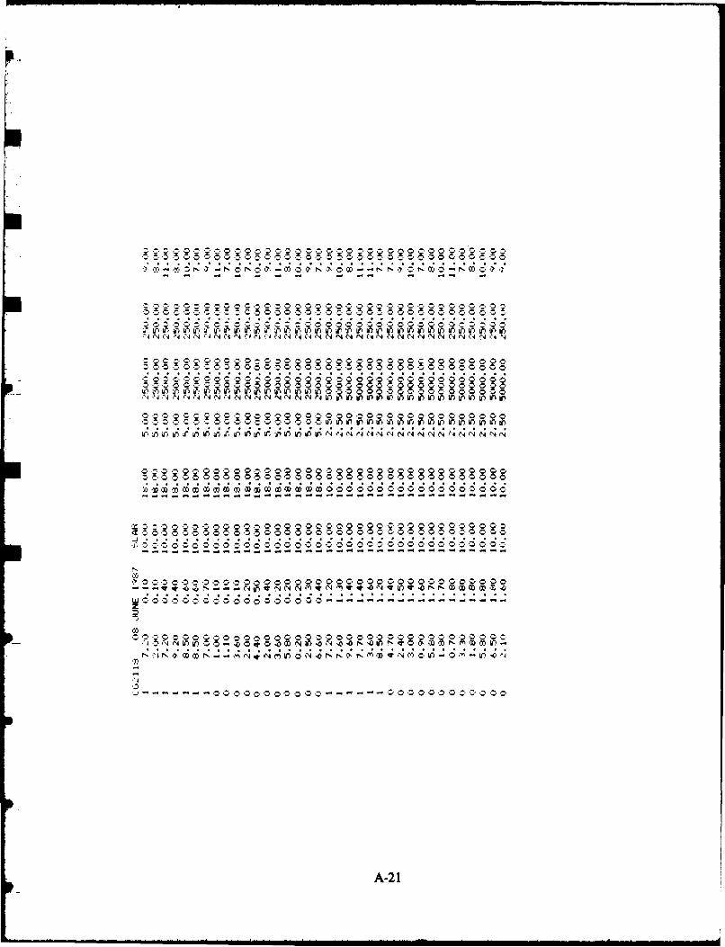
0~ *:o 0 0 z 0.o : 00 .0 0' . .. .. .. ..
11. j 1U '4 U ' 'U 'U 'U'U 'U U N N N N N N N N N N N N N N N N
~ o00 oooo~oo.~0 ooO000000 00000
:0.:000o 00 A000000 o C, 0 0 0 0
0
- OC*0OOO 00 0 0 0 00
0007w00^ 0 0-------oooo 80
0 0 A-21
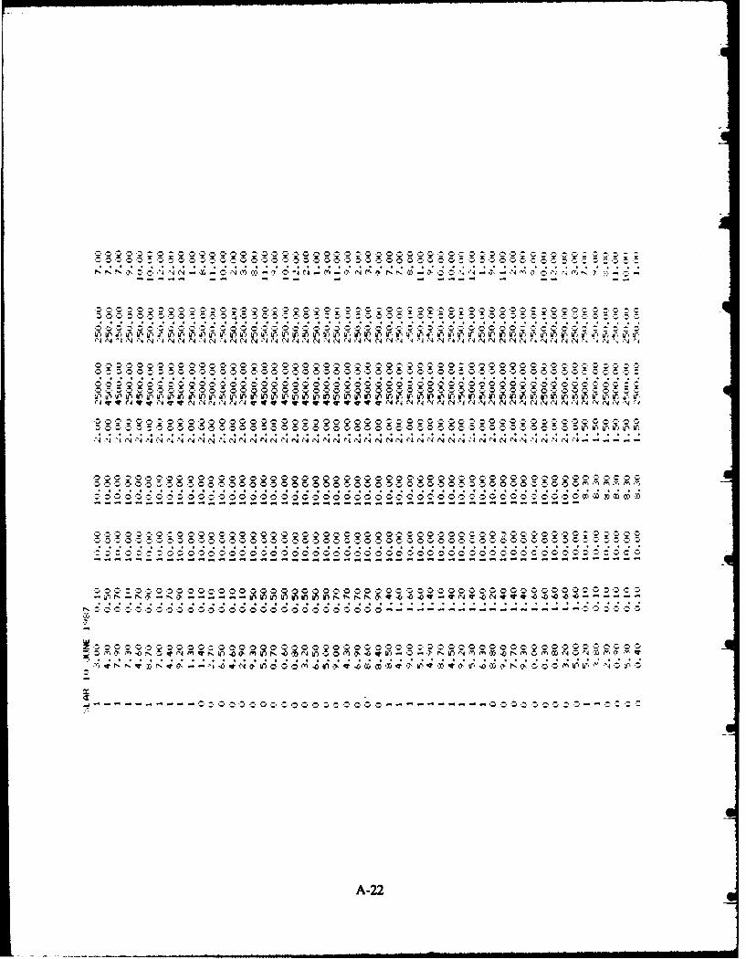
x x X , i
. .~ . . . .
0~~~~~~~~~ Co Z'.C C~C~ O C C O C C.-..
*::.z~oz C:oo C C C.CC C CC C.t:...CooC, t.,L.
i.. . . .rC tou.i.i.o ii.&.L r 0 I.u r r r-. . . ..; 0 i) r.W o0 ir g r.1,0iir .u r r' o r'u- - - r
:' 4 . -'4 NN N 4N N NC -Ci CIN N fC.4N ei Ni"4 4CA iNNN NN NNNC. 4C N -N N N
.c.A A A AI ~~.O 4..9N.( 99..'.' 0- 0 C . .0 0 .0 0 00 0C 0- 00C-. .~ C C C CC O CC O C -------------------------
z .: o. o C o C :: .CC . o.::. . . . .. .. . C..C..CC.:C..C..
0 , ,0 00 0., o00' oc Zc -z
0 00C 0C 0 00 ^05C.00oA--005*X2x c.

ZJ 0' C 0 0-o~r . . nN.
......... .
.*C
N ~0 8t j''N 0 Co, 0 0
I N -W Ir V V IT It I 1w v It Ii ,
• . . . '- ' '> " ,> , 0 0 ,
:.'-- A-., ,
A-23
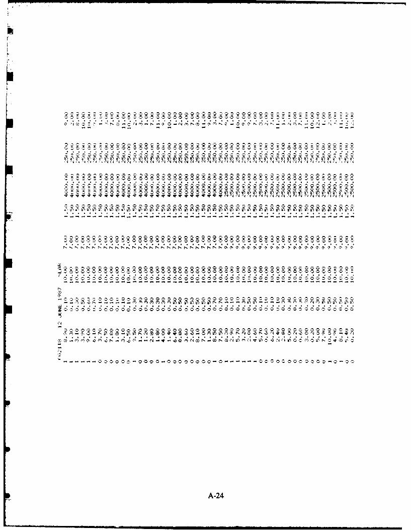
5 .5' .5 .5 5 5' A. A b
~~~.~ .* .~ w .4 . . .N . .'. . .N .~ ' .j .N . .~ . . .'. .~ . . .
A Q5 5 5 0 .7, 5 C. . .~ . . .' .. .~ . . . .r . .' .i .~ . . .C .~ .~ .~ .~ .~ .~ .C .f .C .~I ~( t f ~ VP I C PI C PIlI'I
:~~ ~ ~ ~ -- .- I 7 , . .. 1 .c.- : : 0-. -IN - - ,l ri u 7 r ?
-. IT - ---------.65 )1 r L. U- nir n , 1, -
i N 4 4 ' 'A Ni' I N NN A-NN 4 " * 4NN-4 " AN oJr4NCl'
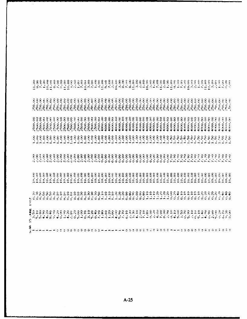
A A
.J~~.O oc oo~ ..-... ....
5-.

- ~ ~*~~'.' U -- M- 0 0 0 o 0 0 -7
XX 0Z:. ooo.000 00 00
*. .0 000 00, 0 00 0: 0 00 0 0 0 0 0
N 'N AJ ' AN N o, N ' N -N 'N N 'N N 'N N N N N N 'N N N N N N N
: 5 5 5 o : 5 5 5 o5- 3: Q: ~ 0.
u-,~~~~~~~ ~ ~ ~ ~ Lr r nu l f oL . r g r r )i )u.i-p q5
oooooooo:00o^*:0.--o0 0 00 0 o0o
o o -Z-2o o 7.,oo 0o 0.' 0 0 00- 0 lo * o -0 CO0 : o0 0 0 050 0 0o 0 0 0 0 o0 0 0 0 75 c 0
-' - - -' -
wz
I ^ . o,. ^..0o.00 0 oO oo Colo00o 0
A-26

C~ C.-C. Z...-.. -..
.. . .;' . . . , . . . . .- . -. . U . . . . -' . .- . •
0 0 0 0 0 0 0 0. 0o Cl
7 17 . , Lo p to, I. ,- a ,Ln n u I ? o U i ,, C. 0 la , 7. ,
_. ... . . ,-
_--.,
. .. .........- 0 C-0 0 7
A *S .74. 'Z I-.4 F4 r4 L j- ' "); m 'C' r 'L .'.
,4 i,4 Zn m Ooi Oi oA C, in 0Cr O
~j ' 4 1-1 '- ""4 1; - rl - ) N " la 0 M D' OD
A-27

.~~ ~ . -. . .,
ww.Z
LOiT i vr %A-L.2r F

7, 53 5 A A
41 LO '**J C. I*r. in ** 4 U. U) Lo iN n
V • V • ,W I N N N 'N N N
- - ,.- - - -, - -. -, -,- - -
. . . . ... . . .. . . .2.
N N N N N N 'N N NN
A-29