Embed Size (px)
Citation preview
Advanced Combustion Engine Technologies FY 2005 Progress Report
II.A.11 HCCI and Stratified-Charge CI Engine Combustion Research
John E. Dec Sandia National Laboratories MS 9053, P.O. Box 969 Livermore, CA 94551-0969
DOE Technology Development Manager: Kevin Stork
Objectives
Project Objective: • Provide the fundamental understanding of homogeneous charge compression ignition (HCCI) combustion
required to overcome the technical barriers to development of practical HCCI engines by industry.
FY 2005 Objectives: • Use chemiluminescence imaging to investigate the effects of naturally occurring charge stratification on
HCCI combustion and the main source of this stratification. • Apply multi-zone modeling in combination with experiments to investigate the effects of thermal
stratification and its potential for extending HCCI operation to higher loads. • Investigate the potential of increased swirl and cooler walls to increase the thermal stratification and
extend operation to higher loads. • Investigate ignition characteristics of gasoline and various single- and dual-component fuels that are
representative of real-fuel constituents. – Work cooperatively with the chemical-kinetics modeling group at Lawrence Livermore National
Laboratory (LLNL) to develop improved kinetic mechanisms for these compounds.
Approach • Develop a chemiluminescence imaging technique, and design a series of experiments to determine the
primary cause of natural charge stratification in HCCI engines. • Develop a multi-zone chemical-kinetic model, apply it to investigate HCCI charge stratification, and
compare results against experimental data. • Combine an experimental study of increased swirl and decreased coolant temperature with KIVA
modeling conducted cooperatively with the University of Michigan. • Conduct well-controlled experiments of the autoignition of representative compounds of each class of
hydrocarbons in real fuels (e.g., alkanes, olefins, and aromatics). Work with LLNL to improve chemical-kinetic mechanisms.
• Work with the analytical chemistry group at LLNL to develop a technique for detailed evaluation of the HCCI exhaust species, and investigate over a range of conditions.
Accomplishments • Showed that the main non-uniformities in HCCI combustion are due to thermal stratification resulting
from heat transfer, and that these non-uniformities slow the heat release rate (HRR) by sequential autoignition of progressively cooler regions.
• Mapped out the effects of combustion-timing retard over a range of operating conditions, showing that it reduces the HRR and why it has limitations.
82
Advanced Combustion Engine Technologies FY 2005 Progress Report
• Showed that timing retard slows the HRR mainly by amplifying the benefit of a fixed stratification. • Completed an investigation of the potential of increased swirl and cooler walls to increase thermal
stratification, and showed the limitations of this technique. • Determined the autoignition behavior of various representative fuel constituents with changes in
equivalence ratio (φ) and intake boost. Worked with the kinetics group at LLNL on improving kinetic mechanisms for these compounds and a surrogate-gasoline mechanism.
• Conducted a preliminary detailed exhaust-speciation study of HCCI emissions for iso-octane and gasoline, in cooperation with an analytical chemistry group at LLNL.
• Made significant progress on a variable valve actuation (VVA) system for our research engine. Actuators are operating on a bench-top cylinder head.
Future Directions • Investigate the importance of boundary-layer combustion in slowing the heat release rate during HCCI
combustion using chemiluminescence imaging from the side of the combustion chamber. • Acquire chemiluminescence spectra throughout the combustion event to investigate how the combustion
chemistry progresses and the effects of fueling rate and fuel type. • Develop the capability for planar laser-induced fluorescence (PLIF) imaging of the fuel distribution, and
apply it to studies of fuel-stratified HCCI. • Investigate the effects of compression ratio on the thermal efficiency, timing-retard limits, pressure-boost
limits, and the use of fuels with various ignition qualities. • Continue exhaust-speciation studies for additional fuels and operating conditions. • Investigate the effects of exhaust gas recirculation (EGR) on HCCI for various fuels and operating
conditions. • Complete development of an electro-hydraulic VVA system and begin initial studies.
Introduction
HCCI engines have significant efficiency and emissions advantages over conventional spark-ignition and diesel engines, respectively. However, several technical barriers must be addressed before it is practical to implement HCCI combustion in production engines. One of these barriers is that high-load operation is limited by excessive cylinder-pressure rise rates and engine knock. Other issues are improving combustion efficiency and controlling hydrocarbon (HC) and carbon monoxide (CO) emissions at low loads, and controlling autoignition timing. As outlined under the accomplishment bullets above, several studies have been conducted over the past year (FY 2005) that provide significant new understanding related to overcoming these technical barriers.
Approach
The investigations conducted during FY 2005 involved a combination of conventional, optical, and
computational diagnostics to build a more complete understanding of the HCCI combustion process than is possible with any one technique alone. Experiments were conducted in our dual-engine laboratory, which is equipped with both all-metal and optically accessible HCCI engines of the same basic design. This facility is designed to allow operation over a wide range of conditions, and it has several features to provide precise control of operating parameters such as combustion phasing, intake pressure, and mass flow rates of the supplied fuel and air.
The metal engine was used to conduct well-characterized parametric studies to isolate specific aspects of HCCI combustion and operational trends. These studies utilized conventional cylinder-pressure analysis and emissions measurements. The optically accessible engine allowed chemiluminescence images to be acquired using both an intensified charged coupled device (CCD) camera that provided very good low-light sensitivity and a high-speed intensified video camera that could follow the
83
Advanced Combustion Engine Technologies FY 2005 Progress Report
evolution of the chemiluminescence through an individual combustion event. In addition, to better understand the effects of charge stratification, a multi-zone version of the Senkin application of CHEMKIN was developed [1] and applied, and the results were compared with experimental data from various parametric studies.
Some investigations involved working cooperatively with other research organizations, in addition to our in-house work. These included a KIVA modeling effort with the University of Michigan, working with the chemical-kinetic modeling group at LLNL to assist the development of kinetic mechanisms, and working with an analytical chemistry group at LLNL to obtain detailed exhaust-speciation data. We have also continued to collaborate with the International Truck and Engine Co. on the development of a VVA system for our engines.
Results
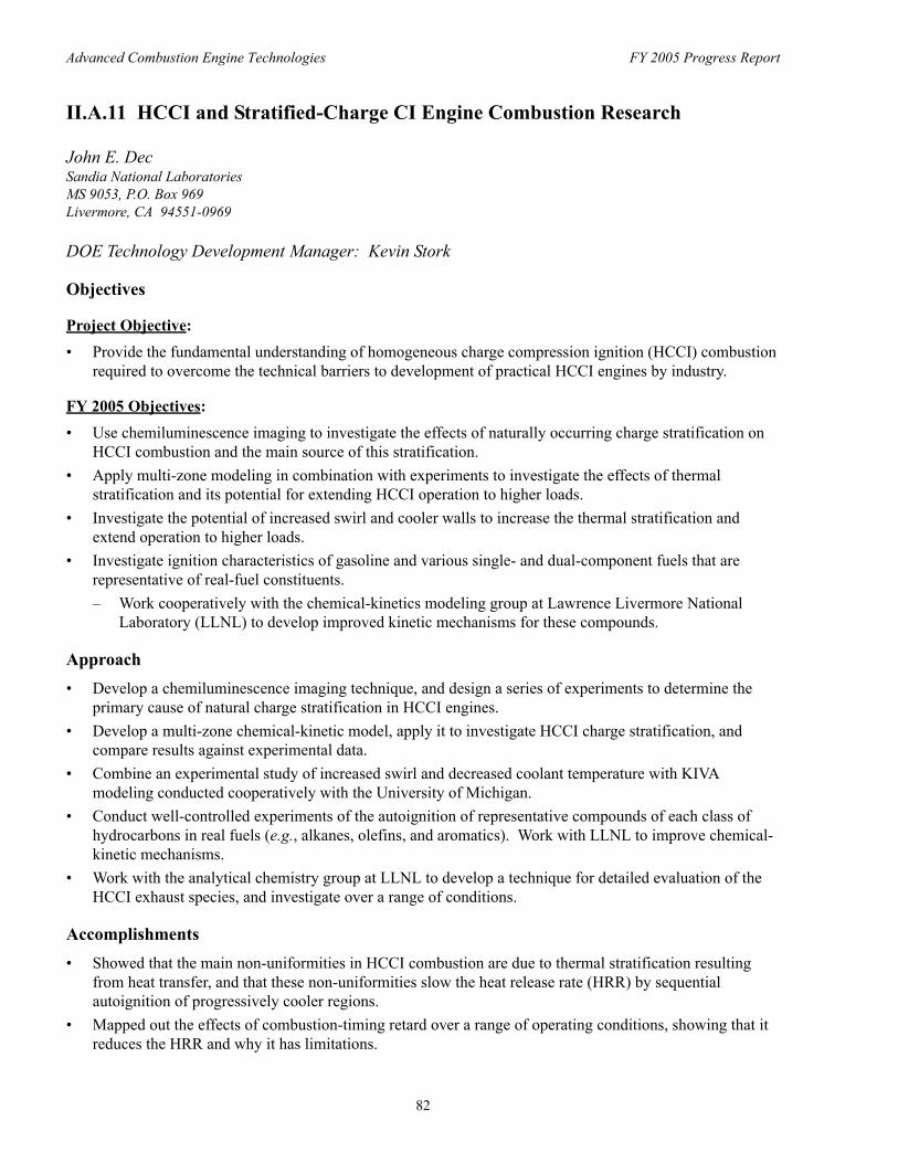
Naturally occurring charge stratification slows the heat-release rate (HRR) in HCCI engines, extending the high-load operating range significantly compared to that of a truly homogeneous-charge engine. To better understand the cause of this stratification, chemiluminescence image sequences were obtained for various operating conditions. These images show that the HCCI combustion is not homogeneous but has a strong turbulent structure, even when the fuel and air are fully premixed prior to intake. Images were acquired with three different fueling strategies to change the possible sources of charge stratification. The results indicate that the combustion inhomogeneities are caused primarily by thermal stratification due to heat transfer during compression, combined with turbulent transport. High-speed movie sequences, like the example in Figure 1, show that this stratification causes the combustion to occur as a sequential autoignition of progressively cooler regions, slowing the HRR and therefore the pressure-rise rate (PRR).
As the fueling rate is increased, the PRR eventually becomes too rapid, causing the engine to knock even with the natural thermal stratification. However, retarding the combustion phasing is effective in further slowing the PRR to allow higher
Figure 1. High-Speed Movie Sequence of HCCI. The interval between frames is 100 µs (0.71°CA) for the first five frames and 200 µs (1.42°CA) for the last five frames; exposure time is 49 µs per frame; φ = 0.24, CA50 = TDC, 1200 rpm.
loads without excessive knock. To better understand this phenomenon and its limitations, a systematic study was conducted. This study showed that stable combustion could be maintained for progressively more timing retard if the fueling rate was simultaneously increased. This allows the fueling to be increased up to an equivalence ratio (φ) of about 0.42 – 0.44, as discussed in detail in Ref. [2].
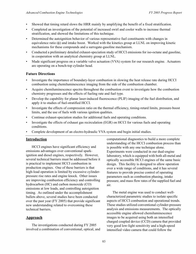
It is important to understand the reason combustion timing retard allows a substantial increase in fueling. The experimental pressure traces in Figure 2 (the smooth curves) provide an example of how timing retard reduces the PRR. It is often considered that this occurs because combustion is cooler with timing retard, so the chemical-kinetic rates are slower, which increases the burn duration. However, chemical-kinetic modeling shows that this cooling effect produces a far smaller increase in the
84
Advanced Combustion Engine Technologies FY 2005 Progress Report
Figure 2. Combustion Phasing Sweeps for the Experiment (smooth curves) and Multi-Zone Model with Four Active Zones. The higher Tbdc temperatures correspond to the more advanced combustion phasings. φ = 0.367.
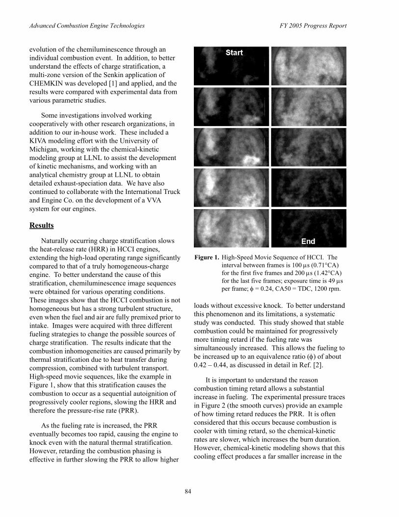
Figure 3. 10-90% Burn Duration vs. 10% Burn Point for the Experiment, Single-Zone Model, and 5-Zone Model, Computed from the Data in Figure 2.
burn duration than is observed experimentally, as evident from a comparison of the experimental and single-zone curves in Figure 3. To further explore this issue, the multi-zone model was applied to account for the effects of the thermal stratification, in addition to the modest slowing of the kinetic rates. Figure 2 shows examples of the modeling results with four active zones, which were found to be sufficient to capture the trends in the PRR. For the results presented, the four zones were initialized with a temperature distribution to match the PRR of the
most advanced pressure curve in Figure 2, simulating the thermal stratification of the engine. This temperature distribution was then held fixed as the model’s combustion phasing was retarded by lowering the initial temperature, as was done experimentally by lowering the intake temperature. As shown in Figures 2 and 3, the resulting changes in the PRR and burn duration track the experiment very closely. Analysis of these results shows that the main reason combustion-timing retard slows the HRR is that it amplifies the effect of the thermal stratification in the bulk-gases, while the effect of slower kinetic rates is of lesser importance. A complete discussion may be found in Ref. [3].
The effects of engine speed were also examined. For a fixed φ, the experimental pressure traces were found to be self-similar when plotted against crank angle degree (°CA) for engine speeds from 600 to 2400 rpm. As a result, the PRR in real time increases with speed, causing an increase in the knock intensity unless φ is reduced. Application of the multi-zone model showed the reason for this behavior and the increase in thermal stratification that would be required to overcome it, as discussed in Ref. [4].
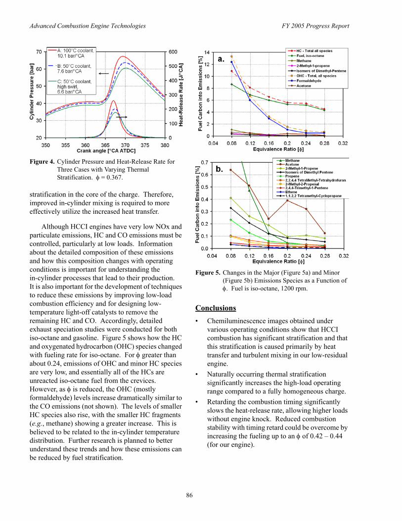
The studies discussed above show that the natural thermal stratification of the charge is critical for achieving the current high-load limit for HCCI operation. Moreover, the multi-zone model indicates that increasing the thermal stratification has the potential to significantly extend this limit. To verify this experimentally and to gain an understanding of the issues involved, the natural thermal stratification was enhanced by increasing the heat transfer rates through reduction in the coolant temperature and increased swirl. As shown in Figure 4, reducing the coolant temperature from the baseline 100°C to 50°C reduces the peak HRR and increases the heat-release duration. This causes the PRR to drop from 10.1 bar/°CA to 7.6/°CA. Increasing the swirl ratio from 0.9 to 3.2 further reduces the PRR. Thus, the technique works, but this relatively simple approach resulted in a fairly large increase in heat transfer losses for a modest reduction in the PRR. Further analysis suggests that this happened because the technique mainly further cooled the boundary-layer regions, but did not produce much additional
85
Advanced Combustion Engine Technologies FY 2005 Progress Report
Figure 4. Cylinder Pressure and Heat-Release Rate for Three Cases with Varying Thermal Stratification. φ = 0.367.
stratification in the core of the charge. Therefore, improved in-cylinder mixing is required to more effectively utilize the increased heat transfer.
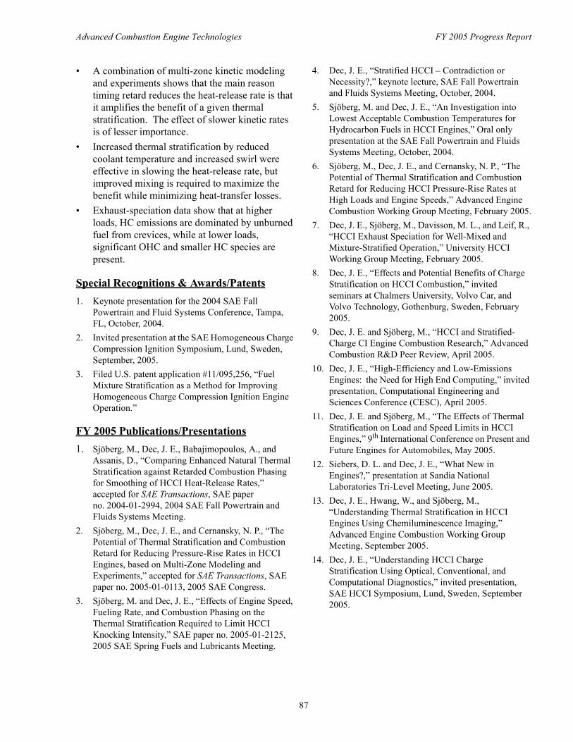
Although HCCI engines have very low NOx and particulate emissions, HC and CO emissions must be controlled, particularly at low loads. Information about the detailed composition of these emissions and how this composition changes with operating conditions is important for understanding the in-cylinder processes that lead to their production. It is also important for the development of techniques to reduce these emissions by improving low-load combustion efficiency and for designing low-temperature light-off catalysts to remove the remaining HC and CO. Accordingly, detailed exhaust speciation studies were conducted for both iso-octane and gasoline. Figure 5 shows how the HC and oxygenated hydrocarbon (OHC) species changed with fueling rate for iso-octane. For φ greater than about 0.24, emissions of OHC and minor HC species are very low, and essentially all of the HCs are unreacted iso-octane fuel from the crevices. However, as φ is reduced, the OHC (mostly formaldehyde) levels increase dramatically similar to the CO emissions (not shown). The levels of smaller HC species also rise, with the smaller HC fragments (e.g., methane) showing a greater increase. This is believed to be related to the in-cylinder temperature distribution. Further research is planned to better understand these trends and how these emissions can be reduced by fuel stratification.
Figure 5. Changes in the Major (Figure 5a) and Minor (Figure 5b) Emissions Species as a Function of φ. Fuel is iso-octane, 1200 rpm.
Conclusions • Chemiluminescence images obtained under
various operating conditions show that HCCI combustion has significant stratification and that this stratification is caused primarily by heat transfer and turbulent mixing in our low-residual engine.
• Naturally occurring thermal stratification significantly increases the high-load operating range compared to a fully homogeneous charge.
• Retarding the combustion timing significantly slows the heat-release rate, allowing higher loads without engine knock. Reduced combustion stability with timing retard could be overcome by increasing the fueling up to an φ of 0.42 – 0.44 (for our engine).
86
Advanced Combustion Engine Technologies FY 2005 Progress Report
• A combination of multi-zone kinetic modeling and experiments shows that the main reason timing retard reduces the heat-release rate is that it amplifies the benefit of a given thermal stratification. The effect of slower kinetic rates is of lesser importance.
• Increased thermal stratification by reduced coolant temperature and increased swirl were effective in slowing the heat-release rate, but improved mixing is required to maximize the benefit while minimizing heat-transfer losses.
• Exhaust-speciation data show that at higher loads, HC emissions are dominated by unburned fuel from crevices, while at lower loads, significant OHC and smaller HC species are present.
Special Recognitions & Awards/Patents 1. Keynote presentation for the 2004 SAE Fall
Powertrain and Fluid Systems Conference, Tampa, FL, October, 2004.
2. Invited presentation at the SAE Homogeneous Charge Compression Ignition Symposium, Lund, Sweden, September, 2005.
3. Filed U.S. patent application #11/095,256, “Fuel Mixture Stratification as a Method for Improving Homogeneous Charge Compression Ignition Engine Operation.”
FY 2005 Publications/Presentations 1. Sjöberg, M., Dec, J. E., Babajimopoulos, A., and
Assanis, D., “Comparing Enhanced Natural Thermal Stratification against Retarded Combustion Phasing for Smoothing of HCCI Heat-Release Rates,” accepted for SAE Transactions, SAE paper no. 2004-01-2994, 2004 SAE Fall Powertrain and Fluids Systems Meeting.
2. Sjöberg, M., Dec, J. E., and Cernansky, N. P., “The Potential of Thermal Stratification and Combustion Retard for Reducing Pressure-Rise Rates in HCCI Engines, based on Multi-Zone Modeling and Experiments,” accepted for SAE Transactions, SAE paper no. 2005-01-0113, 2005 SAE Congress.
3. Sjöberg, M. and Dec, J. E., “Effects of Engine Speed, Fueling Rate, and Combustion Phasing on the Thermal Stratification Required to Limit HCCI Knocking Intensity,” SAE paper no. 2005-01-2125, 2005 SAE Spring Fuels and Lubricants Meeting.
4. Dec, J. E., “Stratified HCCI – Contradiction or Necessity?,” keynote lecture, SAE Fall Powertrain and Fluids Systems Meeting, October, 2004.
5. Sjöberg, M. and Dec, J. E., “An Investigation into Lowest Acceptable Combustion Temperatures for Hydrocarbon Fuels in HCCI Engines,” Oral only presentation at the SAE Fall Powertrain and Fluids Systems Meeting, October, 2004.
6. Sjöberg, M., Dec, J. E., and Cernansky, N. P., “The Potential of Thermal Stratification and Combustion Retard for Reducing HCCI Pressure-Rise Rates at High Loads and Engine Speeds,” Advanced Engine Combustion Working Group Meeting, February 2005.
7. Dec, J. E., Sjöberg, M., Davisson, M. L., and Leif, R., “HCCI Exhaust Speciation for Well-Mixed and Mixture-Stratified Operation,” University HCCI Working Group Meeting, February 2005.
8. Dec, J. E., “Effects and Potential Benefits of Charge Stratification on HCCI Combustion,” invited seminars at Chalmers University, Volvo Car, and Volvo Technology, Gothenburg, Sweden, February 2005.
9. Dec, J. E. and Sjöberg, M., “HCCI and Stratified-Charge CI Engine Combustion Research,” Advanced Combustion R&D Peer Review, April 2005.
10. Dec, J. E., “High-Efficiency and Low-Emissions Engines: the Need for High End Computing,” invited presentation, Computational Engineering and Sciences Conference (CESC), April 2005.
11. Dec, J. E. and Sjöberg, M., “The Effects of Thermal Stratification on Load and Speed Limits in HCCI Engines,” 9th International Conference on Present and Future Engines for Automobiles, May 2005.
12. Siebers, D. L. and Dec, J. E., “What New in Engines?,” presentation at Sandia National Laboratories Tri-Level Meeting, June 2005.
13. Dec, J. E., Hwang, W., and Sjöberg, M., “Understanding Thermal Stratification in HCCI Engines Using Chemiluminescence Imaging,” Advanced Engine Combustion Working Group Meeting, September 2005.
14. Dec, J. E., “Understanding HCCI Charge Stratification Using Optical, Conventional, and Computational Diagnostics,” invited presentation, SAE HCCI Symposium, Lund, Sweden, September 2005.
87
Advanced Combustion Engine Technologies FY 2005 Progress Report
References 1. Lutz, A. E., “Multi-zone Model for Homogeneous
Ignition,” Sandia National Laboratories, Internal Report, July 8, 2002.
2. Sjöberg, M., Dec, J. E., Babajimopoulos, A., and Assanis, D., “Comparing Enhanced Natural Thermal Stratification against Retarded Combustion Phasing for Smoothing of HCCI Heat-Release Rates,” accepted for SAE Transactions, SAE paper no. 2004-01-2994, 2004.
3. Sjöberg, M., Dec, J. E., and Cernansky, N. P., “The Potential of Fuels Annual Report Introduction Thermal Stratification and Combustion Retard for Reducing Pressure-Rise Rates in HCCI Engines, based on Multi-Zone Modeling and Experiments,” accepted for SAE Transactions, SAE paper no. 2005-01-0113, 2005.
4. Sjöberg, M. and Dec, J. E., “Effects of Engine Speed, Fueling Rate, and Combustion Phasing on the Thermal Stratification Required to Limit HCCI Knocking Intensity,” SAE paper no. 2005-01-2125, 2005.
88
Advanced Combustion Engine Technologies FY 2005 Progress Report
II.A.12 Automotive HCCI Combustion Research
Richard Steeper Sandia National Laboratories, MS 9053 P.O. Box 969 Livermore, CA 94551-0969
DOE Technology Development Manager: Kevin Stork
Objectives The focus of the Automotive HCCI Combustion project is the application of advanced optical diagnostics to characterize homogeneous charge compression ignition (HCCI) fuel injection and fuel-air mixing processes, and to understand how mixture preparation strategies affect the combustion and emission performance of automotive HCCI engines. Objectives for FY 2005 were as follows:
• Acquire emissions measurement capability for the Automotive HCCI Lab. • Conduct experiments to understand the effects of charge preparation on combustion. • Assist the development of optical diagnostics and computational models for HCCI engine research.
Approach • Acquisition and installation of emissions equipment. • Acquisition of homogeneous-charge emissions data as the basis of a predictive model of HCCI emissions. • Acquisition of stratified-charge laser-induced fluorescence (LIF) measurements of in-cylinder fuel-air
mixing and simultaneous measurements of engine-out emissions. • Formulation and validation of an emissions prediction method. • Initiation of collaborative projects with Stanford University (temperature diagnostics), and with University
of Wisconsin and Lawrence Livermore National Laboratory (KIVA model).
Accomplishments • Emissions rack and sample conditioning equipment installed and incorporated into lab data acquisition
system. Engine operating protocol developed to enable corresponding measurements of in-cylinder fuel distribution and engine-out emissions.
• An emissions prediction method was developed and tested for predicting hydrocarbon (HC), carbon monoxide (CO), and carbon dioxide (CO2) emissions during low-load stratified operation based on LIF images of in-cylinder equivalence ratio. Successful prediction of HC, CO, and CO2 emissions encourages the use of the method as a tool in developing advanced mixture-preparation strategies.
• Initiated a joint project with Stanford University to apply advanced LIF and tunable diode laser (TDL) diagnostics for the measurement of in-cylinder gas temperatures.
• Initiated a joint project with University of Wisconsin and Lawrence Livermore National Laboratory to implement a KIVA model of the Sandia Automotive HCCI Optical Engine. At the conclusion of the reporting period, gridding of the engine is nearly complete.
Future Directions • Extend the LIF-based prediction method to estimate NOx emissions from stratified HCCI operation.
Apply the prediction method to formulate an enhanced mixing strategy leading to low emissions and high combustion efficiency.
89
Advanced Combustion Engine Technologies FY 2005 Progress Report
• Characterize the charge-preparation process for alternative injectors and injection strategies, using measurements of liquid injection, wall wetting, and fuel-air mixing.
• Continue the collaboration with Stanford to develop temperature diagnostics for application in HCCI optical engines.
• Exercise the KIVA model to guide and interpret engine experiments.
Introduction
Major challenges to the implementation of HCCI combustion—including phasing control, operating-range extension, and emissions control—may well require advanced, non-homogeneous, fuel-air mixing strategies. Alternative injection strategies such as retarded or multiple injections can be used to modify the local equivalence ratios at which combustion takes place, thereby affecting rate of heat release, combustion efficiency, and engine-out emissions. The focus of the current project is the application of in-cylinder optical diagnostics to characterize the fuel-air mixing process and to correlate mixture preparation with the subsequent HCCI combustion.
Approach
The installation of an emissions bench in the Automotive HCCI Engine Lab enabled investigations of the correlation between fuel-air mixture preparation and associated combustion/ emission performance. LIF measurements of in-cylinder equivalence ratio were made while simultaneously recording engine-out emissions. Based on probability density function (PDF) statistics of the LIF data, a prediction algorithm was devised for predicting engine-out emissions, and the predictions were compared to measured HC, CO, and CO2 emissions. Experiments were also begun to test methods for optically measuring charge temperatures.
Results
This year’s principal results derive from the formulation and testing of a method for predicting emissions from stratified HCCI operation that is based on LIF imaging of fuel distribution. The method relies on the simplifying assumption that each local fuel-air packet at a given equivalence ratio burns as if in a homogeneous mixture at the same equivalence ratio. Insofar as this premise holds true, the emissions produced by each packet can be
predicted using a look-up table of exhaust emission values measured during homogeneous operation. The work can be summarized in three steps: 1) measurement of emissions during homogeneous-charge experiments to produce a look-up table of emissions versus equivalence ratio; 2) LIF measurement of equivalence ratio distribution during stratified-charge experiments and simultaneous measurement of emissions; and 3) prediction of emissions using the LIF data and look-up tables, and comparison of the results with measured emissions.
Homogeneous-charge experiments
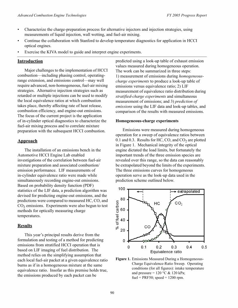
Emissions were measured during homogeneous operation for a sweep of equivalence ratios between 0.1 and 0.3. Results for HC, CO, and CO2 are plotted in Figure 1. Mechanical integrity of the optical engine dictated the load limits, but fortunately the important trends of the three emission species are revealed over this range, so the data can reasonably be extrapolated beyond the limits of the experiments. The three emissions curves for homogeneous operation serve as the look-up data used in the prediction scheme outlined below.
Figure 1. Emissions Measured During a Homogeneous-Charge Equivalence-Ratio Sweep. Operating conditions (for all figures): intake temperature and pressure = 120 °C & 120 kPa; fuel = PRF50; speed = 1200 rpm.
90
Advanced Combustion Engine Technologies FY 2005 Progress Report
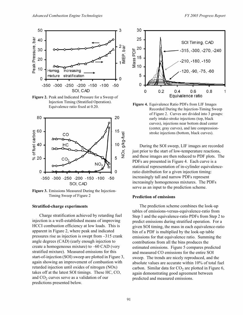
Figure 2. Peak and Indicated Pressure for a Sweep of Injection Timing (Stratified Operation). Equivalence ratio fixed at 0.20.
Figure 3. Emissions Measured During the Injection-Timing Sweep of Figure 2
Stratified-charge experiments
Charge stratification achieved by retarding fuel injection is a well-established means of improving HCCI combustion efficiency at low loads. This is apparent in Figure 2, where peak and indicated pressures rise as injection is swept from –315 crank angle degrees (CAD) (early enough injection to create a homogeneous mixture) to –60 CAD (very stratified mixture). Measured emissions for this start-of-injection (SOI) sweep are plotted in Figure 3, again showing an improvement of combustion with retarded injection until oxides of nitrogen (NOx) takes off at the latest SOI timings. These HC, CO, and CO2 curves serve as a validation of our predictions presented below.
Figure 4. Equivalence Ratio PDFs from LIF Images Recorded During the Injection-Timing Sweep of Figure 2. Curves are divided into 3 groups: early intake-stroke injections (top, black curves), injections near bottom dead center (center, gray curves), and late compression-stroke injections (bottom, black curves).
During the SOI sweep, LIF images are recorded just prior to the start of low-temperature reactions, and these images are then reduced to PDF plots. The PDFs are presented in Figure 4. Each curve is a statistical representation of in-cylinder equivalence-ratio distribution for a given injection timing: increasingly tall and narrow PDFs represent increasingly homogeneous mixtures. The PDFs serve as an input to the prediction scheme.
Prediction of emissions
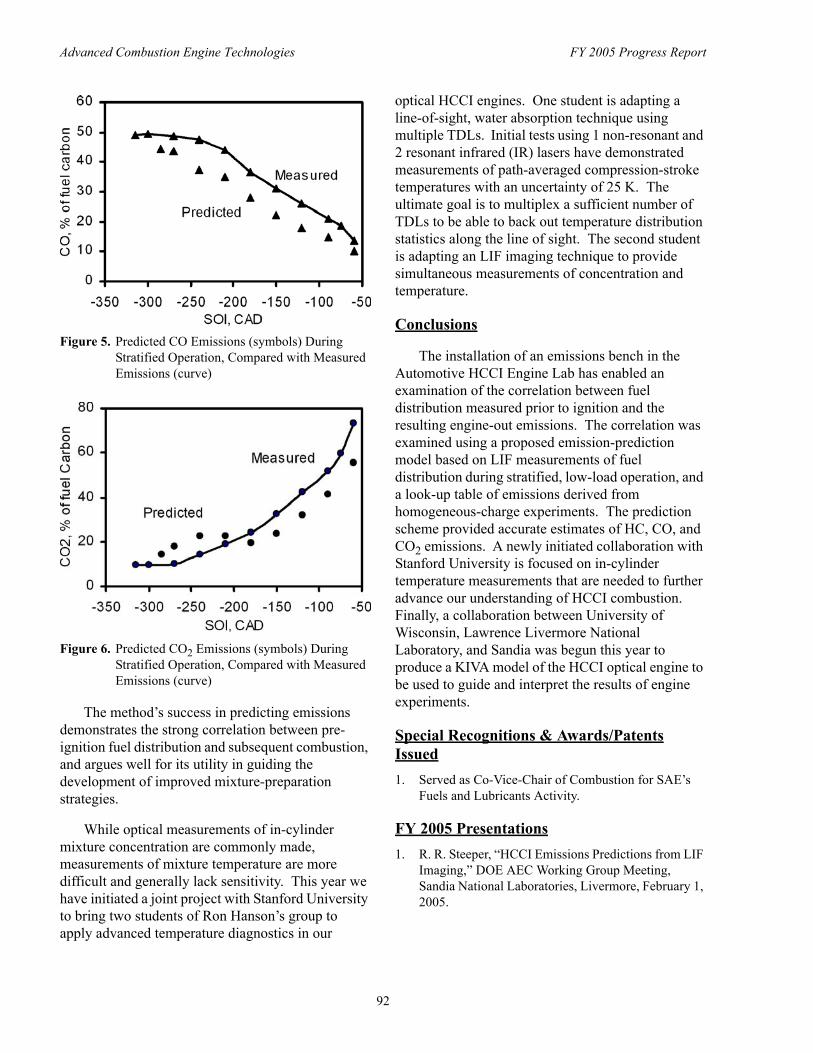
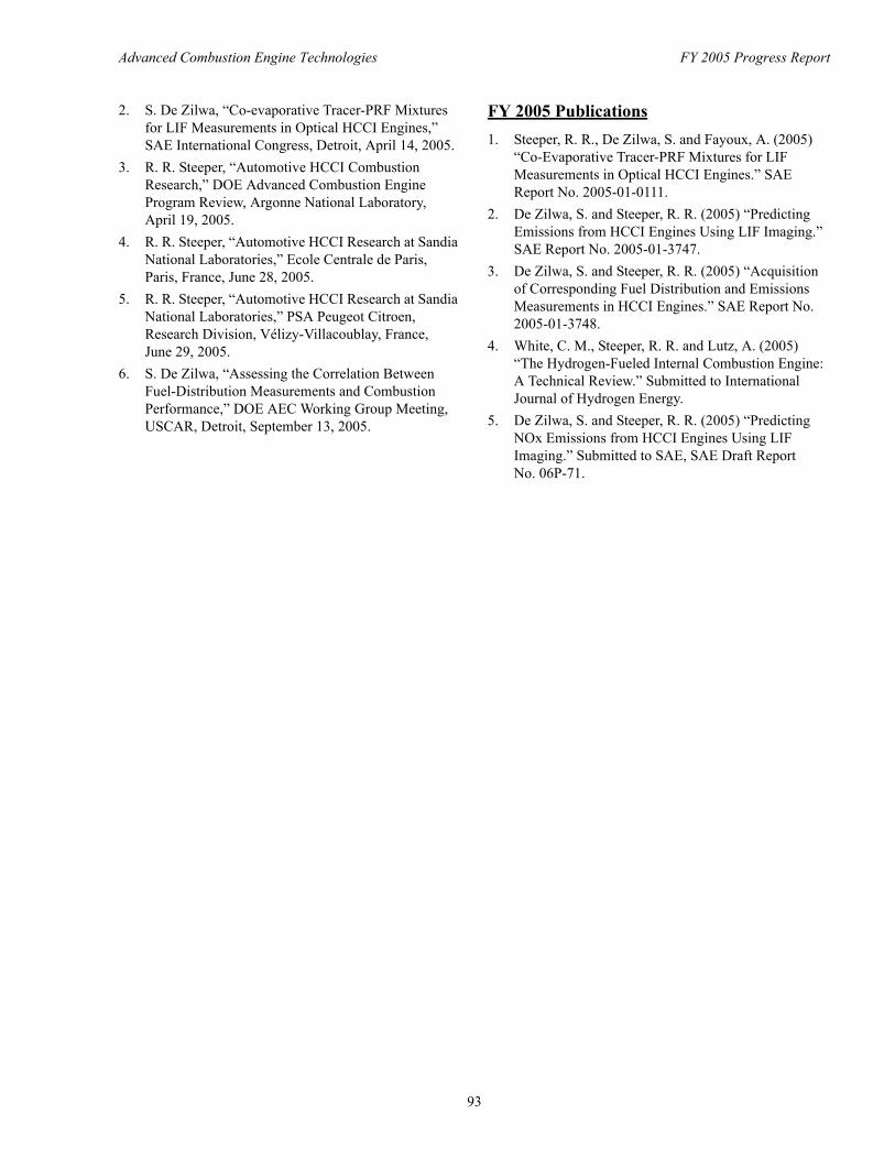
The prediction scheme combines the look-up tables of emissions-versus-equivalence-ratio from Step 1 and the equivalence-ratio PDFs from Step 2 to predict emissions during stratified operation. For a given SOI timing, the mass in each equivalence-ratio bin of a PDF is multiplied by the look-up table emissions for that equivalence ratio. Summing the contributions from all the bins produces the estimated emissions. Figure 5 compares predicted and measured CO emissions for the entire SOI sweep. The trends are nicely reproduced, and the absolute values are accurate within 10% of total fuel carbon. Similar data for CO2 are plotted in Figure 6, again demonstrating good agreement between predicted and measured emissions.
91
Advanced Combustion Engine Technologies FY 2005 Progress Report
Figure 5. Predicted CO Emissions (symbols) During Stratified Operation, Compared with Measured Emissions (curve)
Figure 6. Predicted CO2 Emissions (symbols) During Stratified Operation, Compared with Measured Emissions (curve)
The method’s success in predicting emissions demonstrates the strong correlation between preignition fuel distribution and subsequent combustion, and argues well for its utility in guiding the development of improved mixture-preparation strategies.
While optical measurements of in-cylinder mixture concentration are commonly made, measurements of mixture temperature are more difficult and generally lack sensitivity. This year we have initiated a joint project with Stanford University to bring two students of Ron Hanson’s group to apply advanced temperature diagnostics in our
optical HCCI engines. One student is adapting a line-of-sight, water absorption technique using multiple TDLs. Initial tests using 1 non-resonant and 2 resonant infrared (IR) lasers have demonstrated measurements of path-averaged compression-stroke temperatures with an uncertainty of 25 K. The ultimate goal is to multiplex a sufficient number of TDLs to be able to back out temperature distribution statistics along the line of sight. The second student is adapting an LIF imaging technique to provide simultaneous measurements of concentration and temperature.
Conclusions
The installation of an emissions bench in the Automotive HCCI Engine Lab has enabled an examination of the correlation between fuel distribution measured prior to ignition and the resulting engine-out emissions. The correlation was examined using a proposed emission-prediction model based on LIF measurements of fuel distribution during stratified, low-load operation, and a look-up table of emissions derived from homogeneous-charge experiments. The prediction scheme provided accurate estimates of HC, CO, and CO2 emissions. A newly initiated collaboration with Stanford University is focused on in-cylinder temperature measurements that are needed to further advance our understanding of HCCI combustion. Finally, a collaboration between University of Wisconsin, Lawrence Livermore National Laboratory, and Sandia was begun this year to produce a KIVA model of the HCCI optical engine to be used to guide and interpret the results of engine experiments.
Special Recognitions & Awards/Patents Issued 1. Served as Co-Vice-Chair of Combustion for SAE’s
Fuels and Lubricants Activity.
FY 2005 Presentations 1. R. R. Steeper, “HCCI Emissions Predictions from LIF
Imaging,” DOE AEC Working Group Meeting, Sandia National Laboratories, Livermore, February 1, 2005.
92
Advanced Combustion Engine Technologies FY 2005 Progress Report
2. S. De Zilwa, “Co-evaporative Tracer-PRF Mixtures for LIF Measurements in Optical HCCI Engines,” SAE International Congress, Detroit, April 14, 2005.
3. R. R. Steeper, “Automotive HCCI Combustion Research,” DOE Advanced Combustion Engine Program Review, Argonne National Laboratory, April 19, 2005.
4. R. R. Steeper, “Automotive HCCI Research at Sandia National Laboratories,” Ecole Centrale de Paris, Paris, France, June 28, 2005.
5. R. R. Steeper, “Automotive HCCI Research at Sandia National Laboratories,” PSA Peugeot Citroen, Research Division, Vélizy-Villacoublay, France, June 29, 2005.
6. S. De Zilwa, “Assessing the Correlation Between Fuel-Distribution Measurements and Combustion Performance,” DOE AEC Working Group Meeting, USCAR, Detroit, September 13, 2005.
FY 2005 Publications 1. Steeper, R. R., De Zilwa, S. and Fayoux, A. (2005)
“Co-Evaporative Tracer-PRF Mixtures for LIF Measurements in Optical HCCI Engines.” SAE Report No. 2005-01-0111.
2. De Zilwa, S. and Steeper, R. R. (2005) “Predicting Emissions from HCCI Engines Using LIF Imaging.” SAE Report No. 2005-01-3747.
3. De Zilwa, S. and Steeper, R. R. (2005) “Acquisition of Corresponding Fuel Distribution and Emissions Measurements in HCCI Engines.” SAE Report No. 2005-01-3748.
4. White, C. M., Steeper, R. R. and Lutz, A. (2005) “The Hydrogen-Fueled Internal Combustion Engine: A Technical Review.” Submitted to International Journal of Hydrogen Energy.
5. De Zilwa, S. and Steeper, R. R. (2005) “Predicting NOx Emissions from HCCI Engines Using LIF Imaging.” Submitted to SAE, SAE Draft Report No. 06P-71.
93
Advanced Combustion Engine Technologies FY 2005 Progress Report
II.A.13 HCCI Engine Optimization and Control Using Diesel Fuel
Rolf D. Reitz (Primary Contact), Dave Foster, Jaal Ghandhi, Scott Sanders and Chris Rutland Engine Research Center University of Wisconsin-Madison 1500 Engineering Drive Madison, WI 53706
DOE Technology Development Manager: Kevin Stork
Subcontractor:Prof. D. Haworth, State College, PA
Objectives • Develop methods to optimize and control homogeneous charge compression ignition (HCCI) engines, with
emphasis on diesel-fueled engines. • Use engine experiments and detailed modeling to study factors that influence combustion phasing,
particulate, nitric oxides (NOx), unburned hydrocarbons (HC) and carbon monoxide (CO) emissions. • Provide criteria for transition to other engine operational regimes (e.g., conventional diesel and low-
temperature combustion).
Approach • Use fully instrumented engines with prototype fuel injection systems and combustion sensors to map and
define HCCI combustion regimes, and apply optimization techniques to discover low emissions operation methodologies.
• Develop and apply modeling tools, including multi-dimensional codes (e.g., KIVA with state-of-the-art turbulent combustion and detailed and reduced chemistry models), to reveal combustion mechanisms.
• Develop and apply engine performance models, including multi-dimensional, zero- and one-dimensional global models, for control system development.
• Use homogeneous and stratified charge, and low- and high-pressure fuel injection engine experiments to document fuel injection effects on HCCI ignition and combustion.
Accomplishments • HCCI combustion regimes have been identified on heavy- and light-duty engines using both low pressure
and high pressure, and multiple injection strategies. • Multiple injection strategies have been optimized for low emissions. • HCCI engine operating limits have been shown to be extended by operation with stratified combustion. • System-level analysis tools have been developed for analysis of engine control algorithms, and strategies
for thermal and load changes and mode transitions have been explored. • Novel laser diagnostics have been developed and tested to provide measurements of H2O species and
temperature in HCCI engines for chemistry model validation. • Detailed combustion computations have been used to identify methodologies to increase mixing prior to
ignition for emissions reduction.
94
Advanced Combustion Engine Technologies FY 2005 Progress Report
Introduction
This project was initiated in response to a Department of Energy (DOE) solicitation for research and development on homogeneous charge compression ignition (HCCI) diesel-fueled engines. Advantages of HCCI operation include significantly reduced NOx and particulate emissions. However, there are significant challenges associated with the successful operation of HCCI engines. One of the major difficulties is to control combustion phasing over a wide range of operating conditions. Another obstacle specific to diesel HCCI engine operation is the fact that the early injection required to provide time for fuel-air mixing can lead to wall impingement and, consequently, poor combustion efficiency. The present research applies methods to quantify and overcome these obstacles using a combined experimental and modeling approach.
Approach
The four (4) technical tasks of the present work provide information about HCCI combustion mechanisms for use in knowledge-based engine control schemes. The experiments of Task 1 use a fully instrumented Caterpillar 3401 heavy-duty diesel engine that features electronically controlled fuel injection systems, and a high-speed Yamaha engine that features a variable timing and variable lift valve system. Combustion diagnostics include engine-out particulate, NOx, HC and other gaseous emissions measurements. Computer modeling, coupled with the engine experiments, is used to devise strategies for optimizing and controlling HCCI engine performance and reducing emissions over the speed-load range of interest in applications. The engine performance models include zero- and one-dimensional engine system models for control system development, as described in Task 2. Task 3 provides detailed validation data for chemical kinetics models using a novel laser-based diagnostic system in an optically accessible engine. The influence of turbulence, temperature and mixture inhomogeneity is revealed with highly resolved computational fluid dynamics (CFD) predictions with detailed chemistry in Task 4.
Results
Task 1: HCCI Engine Control and Demonstration
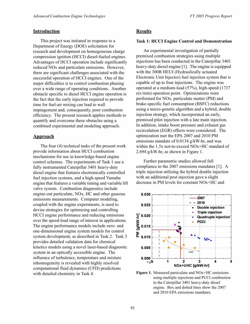
An experimental investigation of partially premixed combustion strategies using multiple injections has been conducted in the Caterpillar 3401 heavy-duty diesel engine [1]. The engine is equipped with the 300B HEUI (Hydraulically actuated Electronic Unit Injector) fuel injection system that is capable of up to four injections. The engine was operated at a medium-load (57%), high-speed (1737 rev/min) operation point. Optimizations were performed for NOx, particulate matter (PM) and brake-specific fuel consumption (BSFC) reductions using a micro-genetic algorithm and a hybrid, double injection strategy, which incorporated an early, premixed pilot injection with a late main injection. In addition, intake boost pressure and exhaust gas recirculation (EGR) effects were considered. The optimization met the EPA 2007 and 2010 PM emissions mandate of 0.0134 g/kW-hr, and was within the 1.5x not-to-exceed NOx+HC standard of 2.694 g/kW-hr, as shown in Figure 1.
Further parametric studies allowed full compliance to the 2007 emissions mandates [1]. A triple injection utilizing the hybrid double injection with an additional post injection gave a slight decrease in PM levels for constant NOx+HC and
Figure 1. Measured particulate and NOx+HC emissions using multiple injections and PCCI combustion in the Caterpillar 3401 heavy-duty diesel engine. Box and dotted lines show the 2007 and 2010 EPA emissions mandates.
95
Advanced Combustion Engine Technologies FY 2005 Progress Report
BSFC levels. Using this strategy and a relatively low level of EGR (<30%) resulted in NOx+HC emissions below the 0.8x 2007 mandates; however, PM levels were higher than the limit. A quadruple injection strategy was evaluated, which added an additional pilot injection to the previous triple injection strategy. This split-pilot strategy with close-coupled post injection resulted in particulate matter (PM) levels below the 0.8x 2007 mandates; however, the NOx emissions were outside of 2007 emissions compliance.
For further NOx reduction, the engine was run with premixed charge compression ignition (PCCI) combustion using EGR levels up to 75% and equivalence ratios up to 0.95 [2]. These experiments resulted in compliance of NOx and PM emissions to 2010 emission levels up to the tested load. However, it was found that NOx+HC levels increased due to the increase of HC with increased engine load, as shown by the arrow in Figure 1.
To help explain the experimental trends, detailed chemistry models have been developed and integrated into the KIVA-CHEMKIN code that use an efficient skeletal reaction mechanism to describe diesel fuel oxidation chemistry [3, 4, 5]. NOx and soot emissions models have also been integrated into the mechanism.
As in the experimental study, genetic algorithms were used for optimization. For example, a two-stage combustion concept has been explored at the high speed (1737 rev/min) and medium load (57% load) condition. As a limiting benchmark case, optimization of the second (late) injection was conducted assuming that a homogeneous mixture has already been formed from a previous first (early) injection before ignition occurs. Four engine operating parameters were optimized: intake valve closure (IVC) timing (used to control combustion phasing), EGR ratio, start of late injection (SOLI) timing and the fraction of fuel in HCCI combustion. The results showed that by combining late IVC timing, late SOLI and medium EGR levels, the two-stage combustion was able to achieve ultra-low (2010 level) engine-out emissions [6].
Extensive data have also been taken with the Yamaha engine to demonstrate HCCI operating
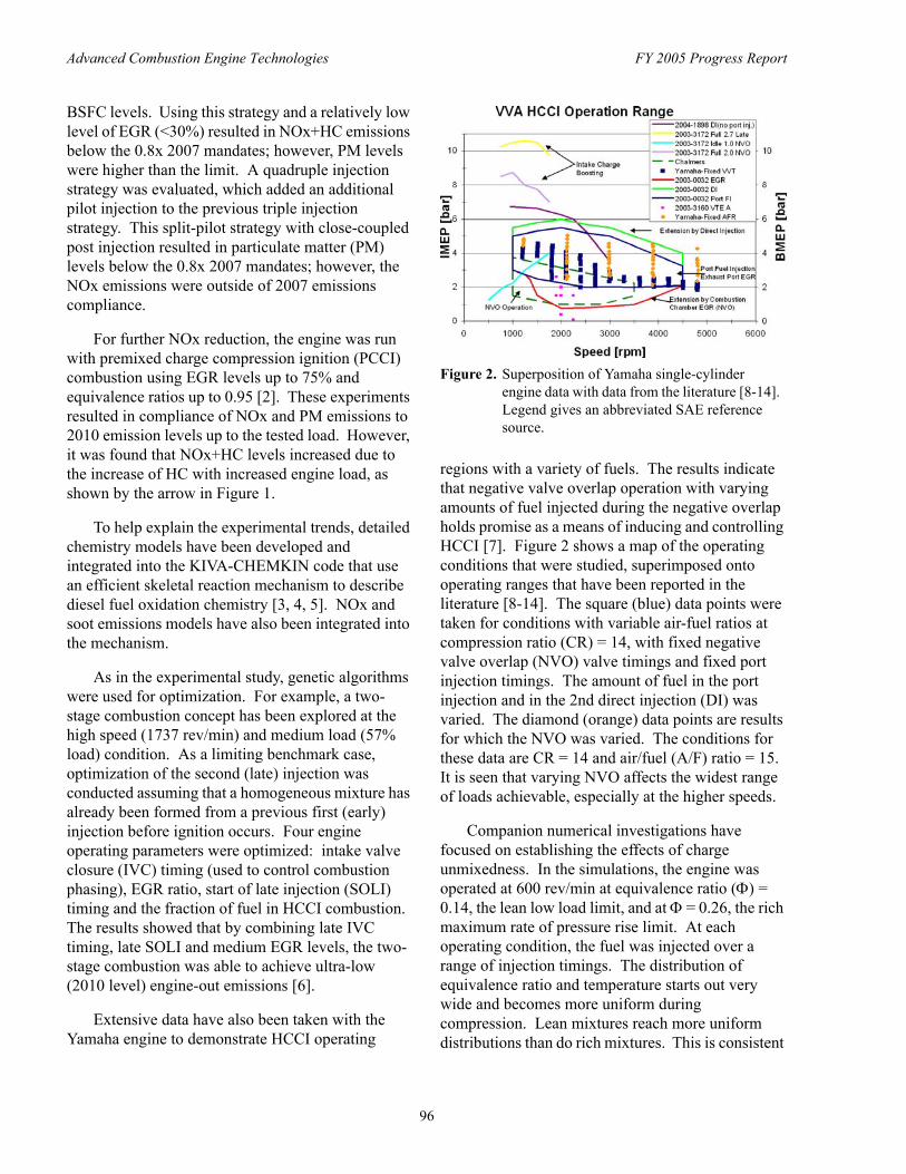
Figure 2. Superposition of Yamaha single-cylinder engine data with data from the literature [8-14]. Legend gives an abbreviated SAE reference source.
regions with a variety of fuels. The results indicate that negative valve overlap operation with varying amounts of fuel injected during the negative overlap holds promise as a means of inducing and controlling HCCI [7]. Figure 2 shows a map of the operating conditions that were studied, superimposed onto operating ranges that have been reported in the literature [8-14]. The square (blue) data points were taken for conditions with variable air-fuel ratios at compression ratio (CR) = 14, with fixed negative valve overlap (NVO) valve timings and fixed port injection timings. The amount of fuel in the port injection and in the 2nd direct injection (DI) was varied. The diamond (orange) data points are results for which the NVO was varied. The conditions for these data are CR = 14 and air/fuel (A/F) ratio = 15. It is seen that varying NVO affects the widest range of loads achievable, especially at the higher speeds.
Companion numerical investigations have focused on establishing the effects of charge unmixedness. In the simulations, the engine was operated at 600 rev/min at equivalence ratio (Φ) = 0.14, the lean low load limit, and at Φ = 0.26, the rich maximum rate of pressure rise limit. At each operating condition, the fuel was injected over a range of injection timings. The distribution of equivalence ratio and temperature starts out very wide and becomes more uniform during compression. Lean mixtures reach more uniform distributions than do rich mixtures. This is consistent
96
Advanced Combustion Engine Technologies FY 2005 Progress Report
with the experimentally measured NOx that is higher for rich cases than for lean cases. To achieve HCCI with low NOx emissions, it appears that the air-fuel ratio stratification must minimize or preclude locally high concentrations of fuel and air.
Task 2 – Engine and System Modeling
Model-based HCCI control concepts require use of system-level models that involve full-cycle simulations of the engine along with all subsystems. However, currently available cycle simulation tools lack advanced models for HCCI combustion. A predictive, computationally efficient cycle simulation tool has been developed to accurately model diesel and gasoline HCCI operation. A commercially available one-dimensional gas dynamics cycle simulation code (GT-Power) was modified to include a multi-zone model [15] (a five-zone combustion model) and a CFD-based combustion model [16]. These models consider fuel injection, vaporization, detailed chemistry calculations, heat transfer, energy conservation and species conservation.
The system modeling predictions were validated with experimental data from the Caterpillar 3401 engine with DI diesel HCCI operation. Parametric studies were conducted to investigate the effect of physical actuators (IVC timing, SOI timing, cooled EGR, intake boost pressure, droplet size). Analysis of transient operation indicated that diesel HCCI benefits from the combined actuation of intake valve closure, injection timing, boost pressure and cooled EGR. Combined actuation can be used for effective phase combustion timing and extending the engine operating range. The influence of different physical actuators on auto-ignition was studied by investigating the effect of each control variable on IVC actuation [17]. It was observed that IVC actuation with varying start of ignition (SOI) is more effective than using IVC actuation with constant SOI.
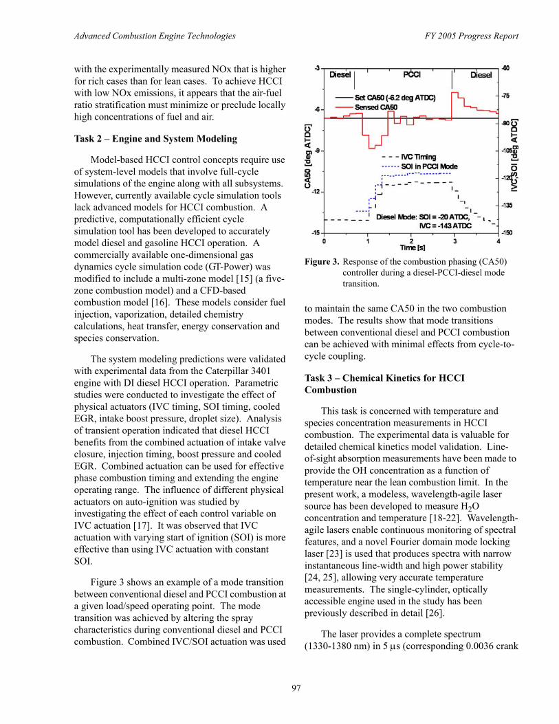
Figure 3 shows an example of a mode transition between conventional diesel and PCCI combustion at a given load/speed operating point. The mode transition was achieved by altering the spray characteristics during conventional diesel and PCCI combustion. Combined IVC/SOI actuation was used
Figure 3. Response of the combustion phasing (CA50) controller during a diesel-PCCI-diesel mode transition.
to maintain the same CA50 in the two combustion modes. The results show that mode transitions between conventional diesel and PCCI combustion can be achieved with minimal effects from cycle-tocycle coupling.
Task 3 – Chemical Kinetics for HCCI Combustion
This task is concerned with temperature and species concentration measurements in HCCI combustion. The experimental data is valuable for detailed chemical kinetics model validation. Line-of-sight absorption measurements have been made to provide the OH concentration as a function of temperature near the lean combustion limit. In the present work, a modeless, wavelength-agile laser source has been developed to measure H2O concentration and temperature [18-22]. Wavelength-agile lasers enable continuous monitoring of spectral features, and a novel Fourier domain mode locking laser [23] is used that produces spectra with narrow instantaneous line-width and high power stability [24, 25], allowing very accurate temperature measurements. The single-cylinder, optically accessible engine used in the study has been previously described in detail [26].
The laser provides a complete spectrum (1330-1380 nm) in 5 µs (corresponding 0.0036 crank
97
Advanced Combustion Engine Technologies FY 2005 Progress Report
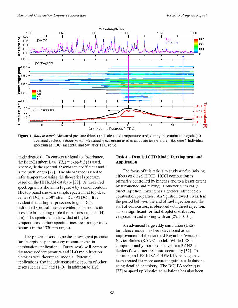
Figure 4. Bottom panel: Measured pressure (black) and calculated temperature (red) during the combustion cycle (50 averaged cycles). Middle panel: Measured spectrogram used to calculate temperature. Top panel: Individual spectrum at TDC (magenta) and 50° after TDC (blue).
angle degrees). To convert a signal to absorbance, Task 4 – Detailed CFD Model Development and
the Beer-Lambert Law (I/Io) = exp(-kνL) is used, where kν is the spectral absorbance coefficient and L is the path length [27]. The absorbance is used to infer temperature using the theoretical spectrum based on the HITRAN database [28]. A measured spectrogram is shown in Figure 4 by a color contour. The top panel shows a sample spectrum at top dead center (TDC) and 50° after TDC (ATDC). It is evident that at higher pressures (e.g., TDC), individual spectral lines are wider, consistent with pressure broadening (note the features around 1342 nm). The spectra also show that at higher temperatures, certain spectral lines are stronger (note features in the 1330 nm range).The present laser diagnostic shows great promise for absorption spectroscopy measurements in combustion applications. Future work will compare the measured temperature and H2O mole fraction histories with theoretical models. Potential applications also include measuring spectra of other gases such as OH and H2O2, in addition to H2O.
Application
The focus of this task is to study air-fuel mixing effects on diesel HCCI. HCCI combustion is primarily controlled by kinetics and to a lesser extent by turbulence and mixing. However, with early direct injection, mixing has a greater influence on combustion properties. An ‘ignition dwell’, which is the period between the end of fuel injection and the start of combustion, is observed with direct injection. This is significant for fuel droplet distribution, evaporation and mixing with air [29, 30, 31].
An advanced large eddy simulation (LES) turbulence model has been developed as an improvement of the standard Reynolds Averaged Navier-Stokes (RANS) model. While LES is computationally more expensive than RANS, it depicts flow structures more accurately [32]. In addition, an LES-KIVA-CHEMKIN package has been created for more accurate ignition calculations using detailed chemistry. The DOLFA technique [33] to speed up kinetics calculations has also been
98
Advanced Combustion Engine Technologies FY 2005 Progress Report
added to the KIVA-CHEMKIN code for full-cycle simulation on a complete engine mesh.
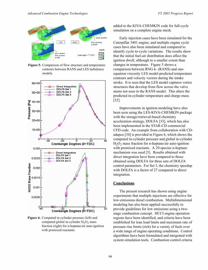
Early injection cases have been simulated for the Caterpillar 3401 engine, and multiple engine cycle cases have also been simulated and compared to identify cycle-to-cycle variations. The results show that the initial fuel-air distribution does affect the ignition dwell, although to a smaller extent than changes in temperature. Figure 5 shows a comparison between RNG k- (RANS) and one-equation viscosity LES model-predicted temperature contours and velocity vectors during the intake stroke. It is seen that the LES model captures vortex structures that develop from flow across the valve stems not seen in the RANS model. This alters the predicted in-cylinder temperature and charge mass [32].
Improvements in ignition modeling have also been seen using the LES-KIVA-CHEMKIN package with the storage/retrieval-based chemistry acceleration strategy, DOLFA [33], which has also been implemented in the STAR-CD commercial CFD code. An example from collaboration with CDadapco [34] is provided in Figure 6, which shows the computed in-cylinder pressure and global in-cylinder H2O2 mass fraction for n-heptane/air auto-ignition with premixed reactants. A 29-species n-heptane mechanism was used [5]. Results obtained with direct integration have been compared to those obtained using DOLFA for three sets of DOLFA control parameters. For Set 3, the chemistry speedup with DOLFA is a factor of 27 compared to direct integration.
Conclusions
The present research has shown using engine experiments that multiple injections are effective for low-emissions diesel combustion. Multidimensional modeling has also been applied successfully to provide guidelines for low emissions using a two-stage combustion concept. HCCI engine operation regions have been identified, and criteria have been established for lean load limits and maximum rate of pressure rise limits (rich) for a variety of fuels over a wide range of engine operating conditions. Control algorithms have been formulated and integrated with system simulation tools. Combustion control criteria
Figure 5. Comparison of flow structure and temperature contours between RANS and LES turbulence models.
Figure 6. Computed in-cylinder pressure (left) and computed global in-cylinder H2O2 mass fraction (right) for n-heptane/air auto-ignition with premixed reactants.
99
Advanced Combustion Engine Technologies FY 2005 Progress Report
based on the use of variable valve timing, boost pressure, EGR and start-of-injection timings have been shown to be effective for improved performance during engine transients. A new laser-based diagnostic has been developed for high-resolution in-cylinder measurements of species concentrations and gas temperature for chemical kinetic model validation. Detailed turbulence and chemistry models have been developed and applied to study mixing control via injection timing, swirl, and valve event timings.
Special Recognitions & Awards/Patents Issued 1. Reitz, R.D., Rutland, C.J., Jhavar, R., “Engine Valve
Actuation for Combustion Enhancement,” U.S. Patent 6,736,106, May 2004.
FY 2005 Publications/Presentations 1. University of Wisconsin DOE HCCI Working Group
Presentation Meetings: February 2005 and September 2005.
2. Reitz, R.D., “CFD Modeling of Diesel HCCI,” SAE Homogeneous Charge Compression Ignition Combustion Symposium, Grand Hotel, Lund, Sweden, September 18-20, 2005.
3. Reitz, R.D., “Computational Fluid Dynamics Modeling of Diesel Engine Combustion and Emissions,” 11th Department of Energy Diesel Engine Emissions Reduction Conference, Palmer House Hilton, Chicago, August 21-25, 2005.
4. Dougan, C.L., Kong, S.-C., and Reitz, R.D., “Modeling the Effects of Variable Intake Valve Timing on Diesel HCCI Combustion at Varying Load, Speed and Boost Pressures,” ASME Spring Technical Conference, Paper ICES2005-1020, McCormick Place Convention Center, Chicago, April 5-7, 2005.
5. Yun, H., Sun, Y., and Reitz, R.D., “An Experimental and Numerical Investigation on the Effect of Post Injection Strategies on Combustion and Emissions in the Low-Temperature Diesel Combustion Regime,” ASME Spring Technical Conference, Paper ICES2005-1043, McCormick Place Convention Center, Chicago, April 5-7, 2005.
6. Liang, L., Jung, C., Kong. S.-C., and Reitz, R.D., “Development of a Semi-Implicit Solver for Detailed Chemistry in I.C. Engine Simulations,” ASME Spring Technical Conference, Paper ICES2005-1005, McCormick Place Convention Center, Chicago, April 5-7, 2005.
7. Liu, Y., and Reitz, R.D., “Optimizing HSDI Diesel Combustion and Emissions Using Multiple Injection Strategies,” SAE Paper 2005-01-0212, 2005.
8. Munnannur, A., Kong, S.-C., and Reitz, R.D., “Performance Optimization of Diesel Engines with Variable Intake Valve Timing via Genetic Algorithms,” SAE Paper 2005-01-0374, 2005.
9. Kim, M., Liechty, M.P., and Reitz, R.D., “Application of Micro-Genetic Algorithms for the Optimization of Injection Strategies in a Heavy-Duty Diesel Engine,” SAE Paper 2005-01-0219, 2005.
10. Ra, Y., and Reitz, R.D., “The Use of Variable Geometry Sprays with Low Pressure Injection for Optimization of Diesel HCCI Engine Combustion,” SAE Paper 2005-01-0148, Selected for SAE Transactions, 2005.
11. Kim, M., Liechty, M.P., and Reitz, R.D., “Optimization of Heavy-Duty Diesel Engine Operating Parameters Using Micro-Genetic Algorithms,” Transactions of KSAE, Vol. 13. No. 2, pp. 101-107, 2005.
12. Kong, S.-C., Ra, Y., and Reitz, R.D., “Performance of Multi-Dimensional Models for Simulating Diesel PCCI Engine Combustion Using Low and High Pressure Injectors,” Accepted for publication, International Journal of Engine Research, Special Issue on HCCI Engines, May, 2005.
13. Yun, H., and Reitz, R.D., “Combustion Optimization in the Low-temperature Diesel Combustion Regime,” Accepted for publication, International Journal of Engine Research, Special Issue on HCCI Engines, May, 2005.
14. Kong, S.C., Kim, H., Reitz, R.D., and Kim, Y., “Comparisons of Combustion Simulation Using Representative Interactive Flamelet Model and Direct Integration of CFD with Detailed Chemistry,” Accepted for publication, ASME Journal of Gas Turbines and Power, October, 2005.
15. Kong, S.-C., Sun, Y., and Reitz, R.D., “Modeling Diesel Spray Flame Lift-Off, Sooting Tendency and NOx Emissions Using Detailed Chemistry with Phenomenological Soot Model,” Accepted for publication, ASME Journal of Gas Turbines and Power, October, 2005.
16. Iverson, R.J., Herold, R.E., Augusta, R., Foster, D.E., Ghandhi, J.B., Eng, J.A., and Najt, P.M., “The Effects of Intake Charge Preheating in a Gasoline-Fueled HCCI Engine,” SAE 2005-01-3742, 2005.
17. Narayanaswamy, K., Hessel, R.P., and Rutland, C.J., “A New Approach to Model DI-Diesel HCCI Combustion for Use in Cycle Simulation Studies,” SAE Paper No. 2005-01-3743, 2005.
100
Advanced Combustion Engine Technologies FY 2005 Progress Report
18. Narayanaswamy, K., and Rutland, C.J., “A Modeling Investigation of Combustion Control Variables during Diesel HCCI Transients,” To appear, 2006 SAE International Congress and Exposition, 2005.
19. Narayanaswamy, K., and Rutland, C.J., “DI-HCCI Engine Control System Development,” University HCCI Working Group Meeting, DOE - Sandia National Labs, February, 2005.
20. Rutland, C.J., and Narayanaswamy, K., “Combustion and Controls Modeling for DI-HCCI Simulations,” 2010 Diesel Emissions Reductions Consortium, June, 2005 & US Car Meeting, Detroit, September, 2005.
21. Narayanaswamy, K., Hessel, R.P., and Rutland, C.J., “A New Approach to Model DI-Diesel HCCI Combustion for Use in Cycle Simulation Studies,” Presented at the SAE Powertrain Conference, San Antonio, October, 2005.
22. Kranendonk, L.A., Walewski, J.W., Kim, T., and Sanders, S.T., “Wavelength-Agile Sensor Applied for HCCI Engine Measurements,” Proc. Comb. Symp., 30, pp. 1619-1627, 2005.
23. Kranendonk, L.A., Bartula, R.J., and Sanders, S.T., “Modeless Operation of a Wavelength-Agile Laser by High-Speed Cavity Length Changes,” Opt. Express, 13(5), pp. 1498-1507, 2005.
24. Kranendonk, L.A., and Sanders, S.T., “Optical Design in Beam Steering Environments with Emphasis on Laser Transmission Measurements,” Appl. Opt., 44(31), pp. 6762-6772, 2005.
25. Sanders, S., “Wavelength-Agile Lasers,” Opt. Photonics News, 16(5), pp. 36-41, 2005.
26. Walewski, J.W., and Sanders, S.T., “Rapid Wavelength Scans Over One Octave and Application to Laser-Induced Fluorescence,” Opt. Lett., 30(18), pp. 2394-2396, 2005.
27. Jhavar, R., and Rutland, C.J., “Effects of Mixing on Early Injection Diesel Combustion,” SAE Paper 2005-01-0154.
28. Jhavar, R., and Rutland, C.J., “Using Large Eddy Simulations to Study Mixing Effects in Early Injection Diesel Engine Combustion,” To appear, 2006 SAE International Congress and Exposition, 2005.
29. Zhang, Y.Z., Kung, E.H., and Haworth, D.C., “A PDF Method for Multidimensional Modeling of HCCI Engine Combustion: Effects of Turbulence/Chemistry Interactions on Ignition Timing and Emissions,” Proc. Combust. Institute 30:2763-2771 (2005).
30. Zhang, Y.Z., Rawat, R., Schmidt, G., Haworth, D., Veljkovic, I., and Plassmann, P., “Acceleration of Detailed Chemistry Calculation in Multidimensional
Engine Modeling Using DOLFA,” 15th International Multidimensional Engine Modeling Users’ Group Meeting, Detroit, MI (10 April 2005).
31. Haworth, D.C., “A Review of Turbulent Combustion Modeling for Multidimensional In-cylinder CFD,” SAE Paper No. 2005-01-0993 (2005). Also in SAE Special Publication SP-1971, pp. 131-160 (2005). To appear in SAE Transactions (2005).
32. Kung, E.H., Zhang, Y.Z., and Haworth, D.C., “A CFD Study of the Effects of Internal EGR on Ignition and Emissions in HCCI Engines,” 4th Joint Meeting of the U.S. Sections of the Combustion Institute, Drexel University, Philadelphia, PA (20-23 March 2005).
33. Zhang, Y.Z. , Kung, E.H, and Haworth, D.C., “PDF-based Modeling of HCCI Engine Combustion,” 4th Joint Meeting of the U.S. Sections of the Combustion Institute, Drexel University, Philadelphia, PA (20-23 March 2005).
34. Haworth, D.C., “Applications of Turbulent Combustion Modeling,” in Turbulent Combustion (L. Vervisch, D. Veynante and J.P.A.J. Van Beeck, Eds.), von Karman Institute for Fluid Dynamics Lecture Series 2005-02, Rhode-Saint-Genèse, Belgium, 7-11 March (2005).
References 1. Hardy, W.L., and Reitz, R.D., “An Experimental
Investigation of Partially-Premixed Combustion Strategies Using Multiple-Injections in a Heavy-Duty Diesel Engine," To appear, 2006 SAE International Congress and Exposition, 2005.
2. Hardy, W.L., and Reitz, R.D., “A Study of the Effects of High EGR, High Equivalence Ratio, and Mixing Time on Emissions Levels in a Heavy-Duty Diesel Engine for PCCI Combustion,” To appear, 2006 SAE International Congress and Exposition, 2005.
3. Kong, S.-C., and Reitz, R.D., “Use of Detailed Chemical Kinetics to Study HCCI Engine Combustion with Consideration of Turbulent Mixing Effects,” ASME Journal of Gas Turbines and Power, Vol. 124 (3), pp. 702-707, 2002.
4. Kong, S.-C., Patel, A., Yin, Q., Klingbeil, A., and Reitz, R.D., “Numerical Modeling of Diesel Engine Combustion and Emissions Under HCCI-Like Conditions with High EGR Levels,” SAE paper 2003-01-1087, 2003.
5. Patel, A., Kong, S.-C., and Reitz, R.D., “Development and Validation of a Reduced Reaction Mechanism for HCCI Engine Simulations,” SAE Paper 2004-01-0558, 2004.
101
Advanced Combustion Engine Technologies FY 2005 Progress Report
6. Sun, Y., and Reitz, R.D., “Modeling Diesel Engine NOx and Soot Reduction with Optimized Two-Stage Combustion,” To appear, 2006 SAE International Congress and Exposition, 2005.
7. Iverson, R.J., Herold, R.E., Augusta, R., Foster, D.E., Ghandhi, J.B., Eng, J.A., Najt, P.M., “The Effects of Intake Charge Preheating in a Gasoline-Fueled HCCI Engine,” SAE 2005-01-3742, 2005.
8. Urata, Y., Awasaka, M., Takanashi, J., Hakozaki, T., Umemoto, A., “A Study of Gasoline-Fueled HCCI Engine Equipped with an Electromagnetic Valve Train,” SAE 2004-01-1898, 2004.
9. Wolters, P., Sabler, W., Geiger, J., Duessmann, M., Dithey, J., “Controlled Auto Ignition Combustion Process with an Electromechanical Valve Train,” SAE 2003-01-0032, 2003.
10. Koopmans, L., and Denbratt, I., “A Four Stroke Camless Engine, Operated in HCCI Mode with Commercial Gasoline,” SAE 2001-01-3610, 2001.
11. Persson, H., Agrell, M., Olsson, J.-O., Johannson, B., Ström, H., “The Effect of Intake Temperature on HCCI Operation Using Negative Valve Overlap,” SAE 2004-01-0944, 2004.
12. Agrel, F., Linderyd, J., Anström, H.-E., Eriksson, B., and Wikander, J., “Transient Control of HCCI Through Combined Intake and Exhaust Valve Actuation,” SAE 2003-01-3172, 2003.
13. Persson, H., Pfeiffer, R., Hultqvist, A., Johansson, B., Ström, H., “Cylinder-to-Cylinder and Cycle-to-Cycle Variations at HCCI Operation with Trapped Residuals,” SAE 2005-01-0130, 2005.
14. Koopmans, L., “Development and Analyses of a Method to Reduce Fuel Consumption for Passenger Car Gasoline Engines,” Chalmers University, Ph.D. Thesis, 2005.
15. Narayanaswamy, K., and Rutland, C.J., “Cycle Simulation Diesel HCCI Modeling Studies and Control,” SAE Paper No. 2004-01-2997, 2004.
16. Narayanaswamy, K., Hessel, R.P., and Rutland, C.J., “A New Approach to Model DI-Diesel HCCI Combustion for Use in Cycle Simulation Studies,” SAE Paper No. 2005-01-3743, 2005.
17. Narayanaswamy, K., and Rutland, C. J., “A Modeling Investigation of Combustion Control Variables during Diesel HCCI Transients,” To appear, 2006 SAE International Congress and Exposition, 2005.
18. Kranendonk, L.A., Caswell, A.W., Myers, A.N., Sanders, S.T., “Wavelength-Agile Laser Sensors for Measuring Gas Properties in Engines,” SAE Paper 2003-01-1116, 2002.
19. Myers, A.M., Kranendonk, L.A., Caswell, A.W., Sanders, S.T., “Wavelength-Agile Sensors for Piston and Aeropropulsion Engines,” Proceedings of the Third Joint Meeting of the US Sections of the Combustion Institute, 2003-PG8, 2003.
20. Walewski, J.W., Borden, M.R., Sanders, S.T., “Wavelength-Agile Laser System Based on Soliton Self-Shift and its Application for Broadband Spectroscopy,” Appl.Phy. B, 79(8), pp. 937-940, 2004.
21. Kranendonk, L.A., Walewski, J.W., Kim, T., Sanders, S.T., “Wavelength-Agile Sensor Applied for HCCI Engine Measurements,” Proc. Comb. Symp., 30, pp. 1619-1627, 2005.
22. Kranendonk, L.A., Bartula, R.J., Sanders, S.T., “Modeless Operation of a Wavelength-Agile Laser by High-Speed Cavity Length Changes,” Opt. Express, 13(5), pp. 1498-1507, 2005.
23. Huber, R., Taira, K., Fujimoto, J.G., “Fourier Domain Mode Locking: Overcoming Limitations of Frequency Swept Light Sources and Pulsed Lasers,” CLEO/Europe - EQEC 2005, CP3-5-THU, 2005.
24. Huber, R., Taira, K., Wojtkowski, M., Ko, T.H., Fujimoto, J.G., Hsu, K., “High Speed Frequency Swept Light Source for Fourier Domain OCT at 20 kHz A-Scan Rate,” Coherence Domain Optical Methods and Optical Coherence Tomography in Biomedicine IX, January 23-26 2005, Anonymous eds., San Jose, CA, United States, 5690, pp. 96-100, 2005.
25. Huber, R., Wojtkowski, M., Taira, K., Fujimoto, J.G., Hsu, K., “Amplified, Frequency Swept Lasers for Frequency Domain Reflectometry and OCT Imaging: Design and Scaling Principles,” Optics Express, 13(9), pp. 3513-3528, 2005.
26. Sanders, S.T., Kim, T., Ghandhi, J.B., “Gas Temperature Measurement during Ignition in an HCCI Engine,” Homogeneous Charge Compression Ignition (HCCI), SP-1742, Anonymous eds. (2003-01-744), 2003.
27. Kranendonk, L.A., and Sanders, S.T., “Optical Design in Beam Steering Environments with Emphasis on Laser Transmission Measurements,” Appl. Opt., 44(31), pp. 6762-6772, 2005.
28. Rothman, L.S., Barbe, A., and Benner, D.C., et al, “The HITRAN Molecular Spectroscopic Database: Edition of 2000 Including Updates through 2001,” J.Quant.Spectrosc.Radiat.Transf., 82, pp. 5-44, 2003.
29. Klingbeil, A., “Particulate and NOx Reduction in a Heavy-Duty Diesel Engine Using High Levels of Exhaust Gas Recirculation and Very Early or Very
102
Advanced Combustion Engine Technologies FY 2005 Progress Report
Late Start of Injection,” MS Thesis, University of Wisconsin-Madison, 2002.
30. Jhavar, R., “A Computational Study of the Impact of Mixing of Homogeneous Charge Compression Ignition,” MS Thesis, University of Wisconsin-Madison, 2003.
31. Jhavar, R., and Rutland, C.J., “Effects of Mixing on Early Injection Diesel Combustion,” SAE Paper 2005-01-0154.
32. Jhavar, R., and Rutland, C.J., “Using Large Eddy Simulations to Study Mixing Effects in Early Injection Diesel Engine Combustion,” To appear, 2006 SAE International Congress and Exposition, 2005.
33. Veljkovic, I., Plassmann, P., Haworth, D., “A Scientific On-line Database for Efficient Function Approximation,” in Computational Science and Its Applications – ICCSA 2003, Lecture Notes in Computer Science (LNCS 2667), Part I, pp. 643-653, Springer Verlag (2003).
34. Zhang, Y., Rawat, R., Schmidt, R., Haworth, D., Veljkovic, I., Plassmann, P., “Acceleration of Detailed Chemistry Calculation in Multidimensional Engine Modeling Using DOLFA,” 15th International Multidimensional Engine Modeling Users’ Group Meeting, Detroit, MI (10 April 2005).
103
Advanced Combustion Engine Technologies FY 2005 Progress Report
II.A.14 HCCI Engine Optimization and Control Using Gasoline
Dennis Assanis University of Michigan (UM) Mechanical Engineering 2045 W.E. Lay Auto. Lab. 1231 Beal Avenue Ann Arbor, MI 48109-2133
DOE Technology Development Manager: Kevin Stork
Subcontractors:Massachusetts Institute of Technology (MIT)Stanford University (SU)University of California, Berkeley (UCB)
Objectives • Develop a homogeneous charge compression ignition (HCCI) engine control system. • Develop full cycle modeling tools. • Investigate chemical kinetics for modeling gasoline HCCI combustion. • Carry out detailed modeling studies of mixing and sprays using computational fluid dynamics (CFD) codes
and validate with optical diagnostics.
Approach • Carry out experimental tests of available HCCI control methods. • Develop a range of HCCI engine models, from simple single-zone to complex CFD codes, in order to
incorporate and share the knowledge base on HCCI as it develops. • Investigate critical chemical kinetic rates and mechanisms for gasoline, and develop and validate reduced
kinetic mechanisms for computationally efficient use in the HCCI engine models. • Validate models with engine experiments and combine models and experiments to develop a workable
engine control system.
Accomplishments • Experimentally demonstrated potential control methods using variable valve events and identified
characteristic times for in-cylinder effects of ∼10 cycles. Found strong effect of wall temperature on combustion phasing with characteristic time of ∼100 cycles. Incorporated direct injection (DI) capability and explored the effects of injection timing on ignition timing.
• Developed several load and combustion phasing controller algorithms and demonstrated them in engine tests using indicated mean effective pressure (IMEP), pressure, ion probe and microphone sensors.
• Constructed a system model based on GT-Power software that integrates experimental burn rate data, a new heat transfer model developed previously, and a new ignition model also developed as part of the consortium. Validated the model with experimental data, including spark ignition (SI)-HCCI transitions and wall temperature effects.
• Used the integrated KIVA-Multizone model developed in 2004 to show the effects on burn rate and combustion efficiency of load and equivalence ratio.
104
Advanced Combustion Engine Technologies FY 2005 Progress Report
• Extended shock tube and Rapid Compression Facility (RCF) measurements of ignition delay for isooctane to include gasoline and several three-component gasoline surrogates. Developed a benchmark data set to test available detailed kinetic models and to aid in developing new models.
• Correlated ignition delay data with a simple autoignition integral and successfully integrated the correlation into the engine-vehicle system model.
• Initiated a new flamelet model approach for partially homogeneous charge compression ignition (PHCCI) to predict ignition and burn rate for application to diesel and DI.
Future Directions
Much of the work described here will be extended in the framework of a new DOE-sponsored University Consortium on low-temperature combustion (LTC) to begin in 2006. The focus of the new consortium will be directed toward exploring the physics and chemistry which limit the speed/load range of HCCI operation and toward finding new methods and strategies of expanding that range for maximum fuel economy benefit. • Engine control experiments will expand and refine current studies of mode transitions and thermal
transients necessary for successful and stable HCCI operation over an expanded speed/load range. Control algorithms will be developed and validated in engine experiments. Current engine setups will be modified to investigate turbo/supercharging and DI applications.
• The engine system models will be used to develop and evaluate workable HCCI control strategies, first for the engine alone, and then as part of a vehicle powertrain. A key goal of this work will be realistic evaluation of proposed strategies for in-vehicle fuel economy improvements.
• Detailed kinetics, CFD and mixing models that have been developed will be applied to generate fast semi-empirical models of ignition and HCCI combustion for ongoing incorporation into the engine system model.
• New tasks will study emission control devices for partially premixed compression ignition (PPCI) engines, spark-assisted HCCI for enhanced control and non-petroleum based fuels for use in LTC engines.
Introduction
HCCI has the potential to dramatically reduce NOx emissions from gasoline internal combustion engines while achieving high thermal efficiencies characteristic of diesels, with lower particulate emissions. Because the ignition occurs indirectly as a result of the compression heating of the charge and is not controlled by a spark plug as in conventional gasoline engines, HCCI has been difficult to implement in practical engines. Recently, as part of the consortium, a strong wall temperature effect has been identified which introduces an additional variable to be taken into account. The primary objective of this research project is to develop, through experiments and modeling, the understanding of the relevant physical and chemical HCCI processes, and to develop and apply practical control strategies. To meet the project objectives, a Multi-University Research Consortium was formed of experts from UM, MIT, SU, and UCB in the areas
of engine, optical diagnostics, numerical modeling, gas dynamics, chemical kinetics and combustion research.
Approach
Our research project, now in its fourth year, collaboratively combines experiments and modeling in order to acquire the knowledge and technology to develop a robust control system for HCCI engines. Both single-cylinder and multi-cylinder engine experiments are addressing issues such as injection strategy, mixture homogeneity, valve timing, exhaust gas recirculation (EGR), intake temperature, fuel properties, cooling strategy, transients and engine mode transitions (e.g., SI-to-HCCI). A range of models of HCCI engines and combustion, from simple single-zone to complex CFD codes, is being used in close coordination with the engine experiments to incorporate the experience gained as it develops. At the same time, extensive studies are
105
Advanced Combustion Engine Technologies FY 2005 Progress Report
underway to develop accurate and reliable chemical kinetic models for practical engine fuels. As the project has matured, the kinetics, engine models, and experiments are now being used to identify HCCI operating ranges and limits and to develop viable control strategies.
Results
Development of an HCCI engine control system
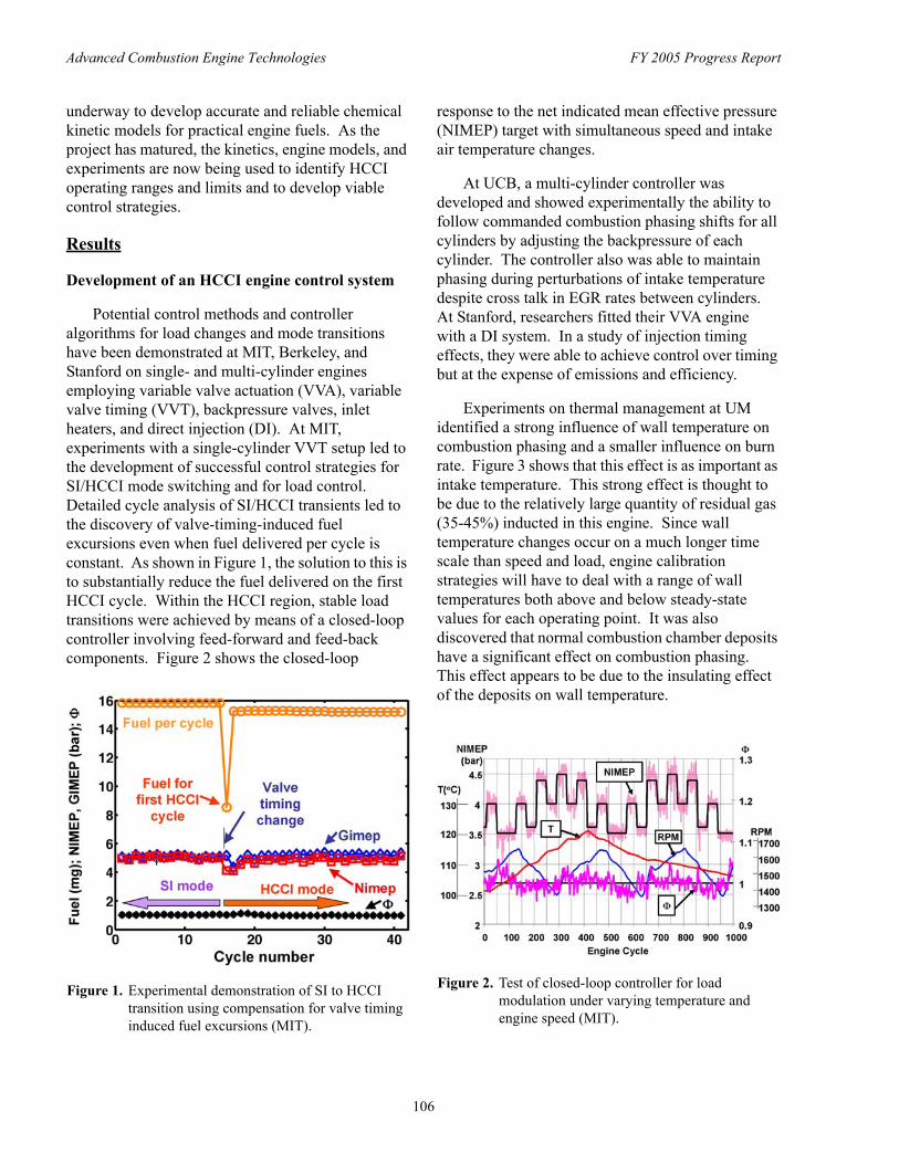
Potential control methods and controller algorithms for load changes and mode transitions have been demonstrated at MIT, Berkeley, and Stanford on single- and multi-cylinder engines employing variable valve actuation (VVA), variable valve timing (VVT), backpressure valves, inlet heaters, and direct injection (DI). At MIT, experiments with a single-cylinder VVT setup led to the development of successful control strategies for SI/HCCI mode switching and for load control. Detailed cycle analysis of SI/HCCI transients led to the discovery of valve-timing-induced fuel excursions even when fuel delivered per cycle is constant. As shown in Figure 1, the solution to this is to substantially reduce the fuel delivered on the first HCCI cycle. Within the HCCI region, stable load transitions were achieved by means of a closed-loop controller involving feed-forward and feed-back components. Figure 2 shows the closed-loop
Figure 1. Experimental demonstration of SI to HCCI transition using compensation for valve timing induced fuel excursions (MIT).
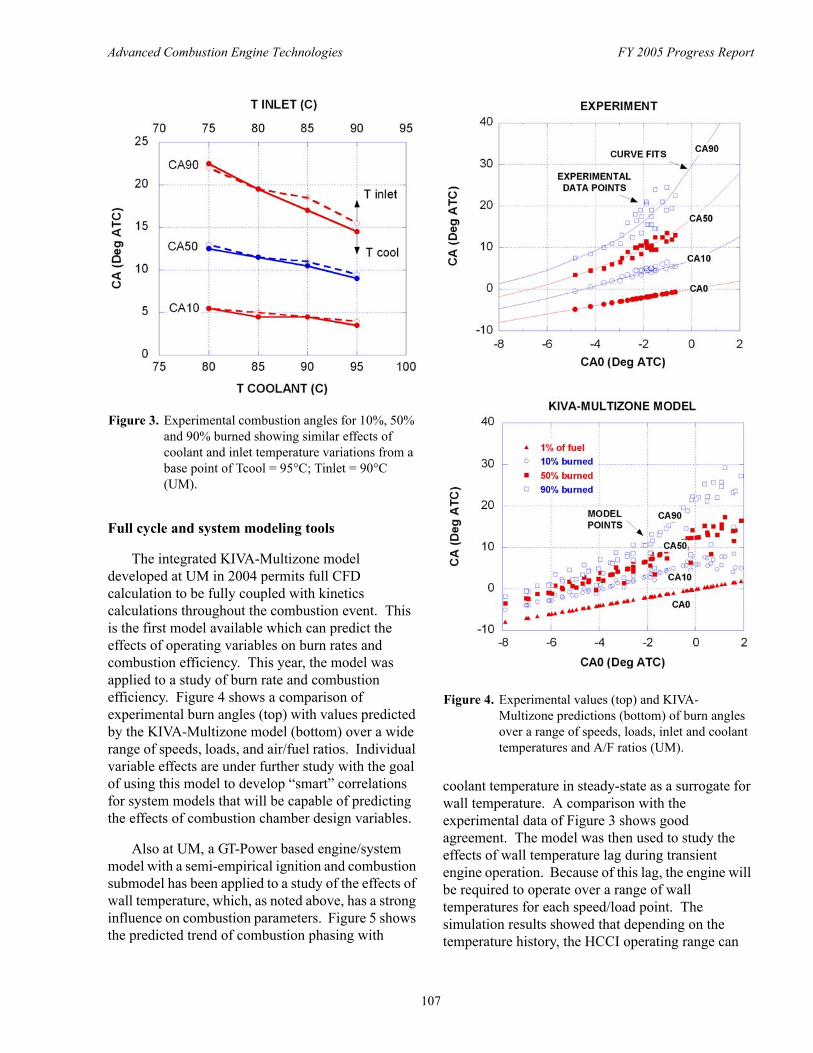
response to the net indicated mean effective pressure (NIMEP) target with simultaneous speed and intake air temperature changes.
At UCB, a multi-cylinder controller was developed and showed experimentally the ability to follow commanded combustion phasing shifts for all cylinders by adjusting the backpressure of each cylinder. The controller also was able to maintain phasing during perturbations of intake temperature despite cross talk in EGR rates between cylinders. At Stanford, researchers fitted their VVA engine with a DI system. In a study of injection timing effects, they were able to achieve control over timing but at the expense of emissions and efficiency.
Experiments on thermal management at UM identified a strong influence of wall temperature on combustion phasing and a smaller influence on burn rate. Figure 3 shows that this effect is as important as intake temperature. This strong effect is thought to be due to the relatively large quantity of residual gas (35-45%) inducted in this engine. Since wall temperature changes occur on a much longer time scale than speed and load, engine calibration strategies will have to deal with a range of wall temperatures both above and below steady-state values for each operating point. It was also discovered that normal combustion chamber deposits have a significant effect on combustion phasing. This effect appears to be due to the insulating effect of the deposits on wall temperature.
Figure 2. Test of closed-loop controller for load modulation under varying temperature and engine speed (MIT).
106
Advanced Combustion Engine Technologies FY 2005 Progress Report
Figure 3. Experimental combustion angles for 10%, 50% and 90% burned showing similar effects of coolant and inlet temperature variations from a base point of Tcool = 95°C; Tinlet = 90°C (UM).
Full cycle and system modeling tools
The integrated KIVA-Multizone model developed at UM in 2004 permits full CFD calculation to be fully coupled with kinetics calculations throughout the combustion event. This is the first model available which can predict the effects of operating variables on burn rates and combustion efficiency. This year, the model was applied to a study of burn rate and combustion efficiency. Figure 4 shows a comparison of experimental burn angles (top) with values predicted by the KIVA-Multizone model (bottom) over a wide range of speeds, loads, and air/fuel ratios. Individual variable effects are under further study with the goal of using this model to develop “smart” correlations for system models that will be capable of predicting the effects of combustion chamber design variables.
Also at UM, a GT-Power based engine/system model with a semi-empirical ignition and combustion submodel has been applied to a study of the effects of wall temperature, which, as noted above, has a strong influence on combustion parameters. Figure 5 shows the predicted trend of combustion phasing with
Figure 4. Experimental values (top) and KIVA-Multizone predictions (bottom) of burn angles over a range of speeds, loads, inlet and coolant temperatures and A/F ratios (UM).
coolant temperature in steady-state as a surrogate for wall temperature. A comparison with the experimental data of Figure 3 shows good agreement. The model was then used to study the effects of wall temperature lag during transient engine operation. Because of this lag, the engine will be required to operate over a range of wall temperatures for each speed/load point. The simulation results showed that depending on the temperature history, the HCCI operating range can
107
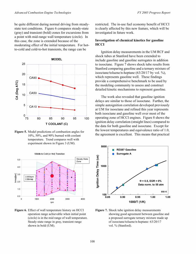
Advanced Combustion Engine Technologies FY 2005 Progress Report
be quite different during normal driving from steady- restricted. The in-use fuel economy benefit of HCCI state test conditions. Figure 6 compares steady-state is clearly affected by this new feature, which will be (gray) and transient (bold) zones for excursions from investigated in future work. a point with mid-range wall temperature (circle). In this case, the zone is extended because of the Investigation of chemical kinetics for gasoline moderating effect of the initial temperature. For hot- HCCI to-cold and cold-to-hot transients, the range can be
Ignition delay measurements in the UM RCF and shock tubes at Stanford have been extended to include gasoline and gasoline surrogates in addition to isooctane. Figure 7 shows shock tube results from Stanford comparing gasoline and a ternary mixture of isooctane/toluene/n-heptane (63/20/17 by vol. %), which represents gasoline well. These findings provide a comprehensive benchmark to be used by the modeling community to assess and construct detailed kinetic mechanisms to represent gasoline.
The work also revealed that gasoline ignition delays are similar to those of isooctane. Further, the simple autoignition correlation developed previously at UM for isooctane and refined this year represents both isooctane and gasoline well over most of the operating zone of HCCI engines. Figure 8 shows the ignition delay correlation (straight lines) compared to the data for both gasoline and isooctane. Except for the lowest temperatures and equivalence ratio of 1.0, the agreement is excellent. This means that practical
Figure 5. Model predictions of combustion angles for 10%, 50%, and 90% burned with coolant temperature. Trend compares well with experiment shown in Figure 3 (UM).
Figure 6. Effect of wall temperature history on HCCI operation range achievable when initial point (circle) is in the mid range of wall temperature. Steady-state range in gray, transient range shown in bold (UM).
Figure 7. Shock tube ignition delay measurements showing good agreement between gasoline and a proposed surrogate ternary mixture made up of isooctane/toluene/n-heptane: 63/20/17 vol. % (Stanford).
108
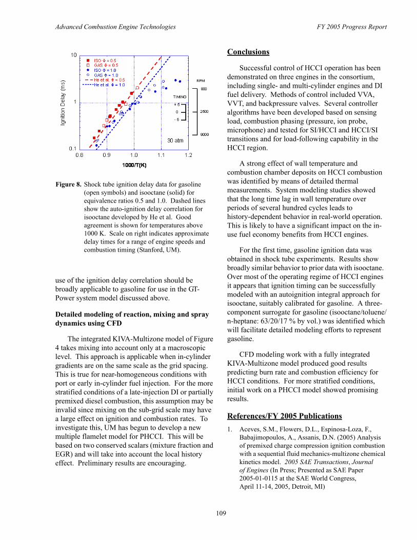
Advanced Combustion Engine Technologies FY 2005 Progress Report
Figure 8. Shock tube ignition delay data for gasoline (open symbols) and isooctane (solid) for equivalence ratios 0.5 and 1.0. Dashed lines show the auto-ignition delay correlation for isooctane developed by He et al. Good agreement is shown for temperatures above 1000 K. Scale on right indicates approximate delay times for a range of engine speeds and combustion timing (Stanford, UM).
use of the ignition delay correlation should be broadly applicable to gasoline for use in the GT-Power system model discussed above.
Detailed modeling of reaction, mixing and spray dynamics using CFD
The integrated KIVA-Multizone model of Figure 4 takes mixing into account only at a macroscopic level. This approach is applicable when in-cylinder gradients are on the same scale as the grid spacing. This is true for near-homogeneous conditions with port or early in-cylinder fuel injection. For the more stratified conditions of a late-injection DI or partially premixed diesel combustion, this assumption may be invalid since mixing on the sub-grid scale may have a large effect on ignition and combustion rates. To investigate this, UM has begun to develop a new multiple flamelet model for PHCCI. This will be based on two conserved scalars (mixture fraction and EGR) and will take into account the local history effect. Preliminary results are encouraging.
Conclusions
Successful control of HCCI operation has been demonstrated on three engines in the consortium, including single- and multi-cylinder engines and DI fuel delivery. Methods of control included VVA, VVT, and backpressure valves. Several controller algorithms have been developed based on sensing load, combustion phasing (pressure, ion probe, microphone) and tested for SI/HCCI and HCCI/SI transitions and for load-following capability in the HCCI region.
A strong effect of wall temperature and combustion chamber deposits on HCCI combustion was identified by means of detailed thermal measurements. System modeling studies showed that the long time lag in wall temperature over periods of several hundred cycles leads to history-dependent behavior in real-world operation. This is likely to have a significant impact on the in-use fuel economy benefits from HCCI engines.
For the first time, gasoline ignition data was obtained in shock tube experiments. Results show broadly similar behavior to prior data with isooctane. Over most of the operating regime of HCCI engines it appears that ignition timing can be successfully modeled with an autoignition integral approach for isooctane, suitably calibrated for gasoline. A three-component surrogate for gasoline (isooctane/toluene/ n-heptane: 63/20/17 % by vol.) was identified which will facilitate detailed modeling efforts to represent gasoline.
CFD modeling work with a fully integrated KIVA-Multizone model produced good results predicting burn rate and combustion efficiency for HCCI conditions. For more stratified conditions, initial work on a PHCCI model showed promising results.
References/FY 2005 Publications 1. Aceves, S.M., Flowers, D.L., Espinosa-Loza, F.,
Babajimopoulos, A., Assanis, D.N. (2005) Analysis of premixed charge compression ignition combustion with a sequential fluid mechanics-multizone chemical kinetics model. 2005 SAE Transactions, Journal of Engines (In Press; Presented as SAE Paper 2005-01-0115 at the SAE World Congress, April 11-14, 2005, Detroit, MI)
109
Advanced Combustion Engine Technologies FY 2005 Progress Report
2. Babajimopoulos, A., Assanis, D.N., Flowers, D.L., Aceves, S.M., Hessel, R.P. (2005) A fully coupled computational fluid dynamics and multi-zone model with detailed chemical kinetics for the simulation of premixed charge compression ignition engines. International Journal of Engine Research, vol. 6, no. 5, pp. 497-512
3. Babajimopoulos, A., Lavoie, G.A. and Assanis, D.N. (2005) On the role of top dead center conditions in the combustion phasing of homogeneous charge compression ignition engines. Combustion Science and Technology (Submitted)
4. Caton, P.A. et al. (2003) Residual-effected homogeneous charge compression ignition at a low compression ratio using exhaust reinduction. International Journal of Engine Research, vol. 4, no. 3
5. Caton, P.A., Song, H.H., Kaahaaina, N.B., and Edwards, C.F. (2005) Residual-effected homogeneous charge compression ignition with asymmetric compression-expansion ratios and elevated compression ratio. International Journal of Engine Research, vol. 6
6. Caton, P.A., Song, H.H., Kaahaaina, N.B., and Edwards, C.F. Strategies for achieving residual-effected homogeneous charge compression ignition using variable valve actuation. SAE paper 2005-01-0165, accepted for publication in the SAE Transactions, Journal of Engines
7. Chang, K., Babajimopoulos, A., Lavoie, G.A., Filipi, Z.S., Assanis, D.N. (2005) Analysis of load and speed transitions in an HCCI engine using 1-D cycle simulation and thermal networks. Submitted for presentation at the SAE World Congress, April 3-7, 2006, Detroit, MI
8. Flowers, D., Aceves, S., Babajimopoulos, A. (2005) Effect of charge non-uniformity on heat release and emissions in PCCI engine combustion. Submitted for presentation at the SAE World Congress, April 3-7, 2006, Detroit, MI
9. Chen, J.H., Hawkes, E.R., Sankaran, R., Im, H.G., and Mason, S.D. (2005) Ignition front propagation in a constant volume with temperature inhomogeneities. Combustion and Flame, in press
10. Chesa Rocafort, L., Andreae, M., Green, W.H., Cheng, W.K. and Cowart, J.S. (2005) A modeling investigation into the optimal intake and exhaust valve event duration and timing for a homogenous charge compression ignition engine. SAE 2005-01-3746
11. Davidson, D.F., Oehlschlaeger, M.A. and Hanson, R.K. “Methyl Concentration Time Histories during iso-Octane and n-Heptane Oxidation,” Paper 05F-61, Western States Section of the Combustion Institute Fall Meeting, Stanford University, Stanford, CA, October 2005.
12. Davidson, D.F., Oehlschlaeger, M.A. and Hanson, R.K. “Methyl Concentration Time Histories during iso-Octane and n-Heptane Oxidation and Pyrolysis,” Proceedings of the Combustion Institute 31, submitted 2005.
13. Hamosfakidis, V., Im, H.G., and Assanis, D.N. “A Regenerative Multiple Flamelet Model for PPCI Engine Simulations,” Technical Meeting of the Eastern States Section, The Combustion Institute, University of Central Florida, Orlando, FL, November 13-15, 2005.
14. He, X., Donovan, M.T., Zigler, B.T., Palmer, T.R., Walton, S.M., Wooldridge, M.S., and Atreya, A. (2005) An experimental study of isooctane ignition delay times at HCCI operating conditions using a Rapid Compression Facility. Combustion and Flame, 142, 266-275
15. He, X., Walton, S.M., Zigler, B.T., Wooldridge, M.S., and Atreya, A. A Rapid Compression Facility study of OH concentrations of isooctane ignition. Paper #C09, The 4th Joint Meeting of the U.S. Sections of the Combustion Institute, March 20-23, 2005, pp. 1-6
16. He, X., Zigler, B.T., Walton, S.M., Wooldridge, M.S., and Atreya, A. (2005) A Rapid Compression Facility study of OH time histories during iso-octane ignition. Submitted to Combustion and Flame, July 5, 2005, accepted October 2005
17. Matthews, J., Santoso, H. and Cheng, W.K. (2005) Load control for an HCCI engine. SAE Paper 2005-01-0150, SAE Congress
18. Mattison, D.W., Jeffries, J.B., and Hanson, R.K. Tunable diode laser sensors for harsh combustion environments with applications to pulse detonation engines and internal combustion engines. Paper A41, Joint Meeting of US Sections of Combustion Institute, Philadelphia, PA, March 2005.
19. Mattison, D.W., Steeper, R.R., De Zilwa, S., Jeffries, J.B. and Hanson, R.K. “In-Cylinder Gas Temperature Measurements in an HCCI Engine Using a Multiplexed-Wavelength TDL System: Sensor Development and Initial Demonstration,” Proceedings of the Combustion Institute 31, submitted 2005.
110
Advanced Combustion Engine Technologies FY 2005 Progress Report
20. Oehlschlaeger, M.A., Davidson, D.F. and Hanson, R.K. (2004) High-temperature thermal decomposition of iso-butane and n-butane behind shock waves. The Journal of Physical Chemistry A 108, 4247-4253
21. Oehlschlaeger, M.A., Davidson, D.F. and Hanson, R.K. “Thermal Decomposition of Toluene: Overall Rate and Branching Ratio,” Proceedings of the Combustion Institute 31, submitted 2005.
22. Sankaran, R. and Im, H.G. (2005) Characteristics of auto-ignition in a stratified iso-octane mixture with exhaust gases under HCCI conditions. Combustion Theory and Modeling, 9, 417-432
23. Sankaran, R., and Im, H.G. “A Theoretical Study on the Effects of Thermal Stratification on the Operating Range of HCCI Engines,” 4th Joint Meeting of the U.S. Sections of the Combustion Institute, The Combustion Institute, Drexel University, Philadelphia, PA, March 20-23, 2005.
24. Sankaran, R., Im, H.G., and Hewson, J.C. (2005) Analytical model for auto-ignition in a thermally stratified HCCI engine. Combustion Science and Technology, submitted
25. Sankaran, R., Im, H.G., Hawkes, E.R., and Chen, J.H. (2005) The effects of nonuniform temperature distribution on the ignition of a lean homogeneous hydrogen-air mixture. Proceedings of the Combustion Institute, 30, 875-882
26. Santoso, H., Matthews J. and Cheng, W K. “Managing SI/HCCI Dual-Mode Engine Operation,” SAE Paper 2005-01-0162, SAE Congress 2005.
27. Santoso, H., Matthews, J. and Cheng, W K. “Characteristics of HCCI Engine Operating in the Negative-Valve-Overlap Mode,” SAE Paper 200501-2133, 2005.
28. Shaver, G.M., Roelle, M., Gerdes, J.C., Caton, P.A., and Edwards, C.F. (2005) Multi-cycle modeling of HCCI engines utilizing variable valve actuation. Accepted for ASME Journal of Dynamic Systems, Measurement and Control, vol. 127, p. 374
29. Vasu, S.S., Davidson, D.F. and Hanson, R.K. “Shock Tube Measurements and Modeling of Ignition Delay Time in Lean Iso-Octane/Air,” Paper 1168, International Symposium on Shock Waves 25, Bangalore, India, July 2005.
30. Walton, S.M., He, X., Zigler, B.T., Wooldridge, M.S., and Atreya, A., “Demonstration of Distinct Ignition Regimes Using High-Speed Digital Imaging of Isooctane Mixtures,” Paper #A29, The 4th Joint Meeting of the U.S. Sections of the Combustion Institute, March 20-23, 2005, pp. 1-6.
111
Advanced Combustion Engine Technologies FY 2005 Progress Report
II.A.15 Spark-Assisted HCCI Combustion
Robert M. Wagner (Primary Contact), Bruce G. Bunting Oak Ridge National Laboratory 2360 Cherahala Boulevard Knoxville, TN 37932
DOE Technology Development Manager: Kevin Stork
Objectives • Evaluate spark augmentation as a potential method for stabilizing and expanding the operating range of
advanced combustion strategies. • Investigate spark augmentation for enabling and/or stabilizing the transition between conventional and
advanced combustion operating modes.
Approach • Perform spark ignition (SI), homogeneous charge compression ignition (HCCI) combustion, and SI-HCCI
transition experiments on a single-cylinder research engine at AVL Powertrain Engineering. • Characterize dynamic structure in cyclic dispersion using methods from nonlinear dynamics theory.
Accomplishments • Confirmed advantages (e.g., improved efficiency, reduced NOx emissions) of HCCI combustion as
compared to throttled conventional SI engine operation. • Spark assist enabled transition to HCCI combustion and extended the stable operating range. • Identified and characterized the existence of deterministic structure in the transition region between SI and
HCCI combustion modes.
Future Directions • Ascertain whether nonlinear analysis is well suited for characterizing and developing control
methodologies for HCCI and HCCI-like combustion modes. • Develop low-order physics based SI-HCCI engine model for evaluating potential control strategies.
Introduction
Gasoline engines are expected to dominate the U.S. passenger car market for at least the next decade. An improvement in the fuel efficiency of these engines would result in a significant reduction in U.S. energy usage. HCCI in internal combustion engines is of considerable interest because of the potential reductions in flame temperature and nitrogen oxide (NOx) emissions as well as potential fuel economy improvements resulting from unthrottled operation, faster heat release, and reduced heat transfer losses. Unfortunately, it is clear that for many transportation applications, it may not be
possible to sustain HCCI under all conditions of speed and load. Thus, the most important technical developments needed to achieve wide-spread HCCI utilization are expanding the operating range and developing the ability to rapidly switch between HCCI and traditional propagating flame (e.g., spark ignition) combustion as power and speed change. It is also clear that there are many engine conditions under which HCCI is physically possible but marginally stable, so that the full potential of HCCI cannot be realized until appropriate stabilizing strategies are developed to maximize the practical range of implementation. Several recent publications and presentations [1-4] have begun to address the
112
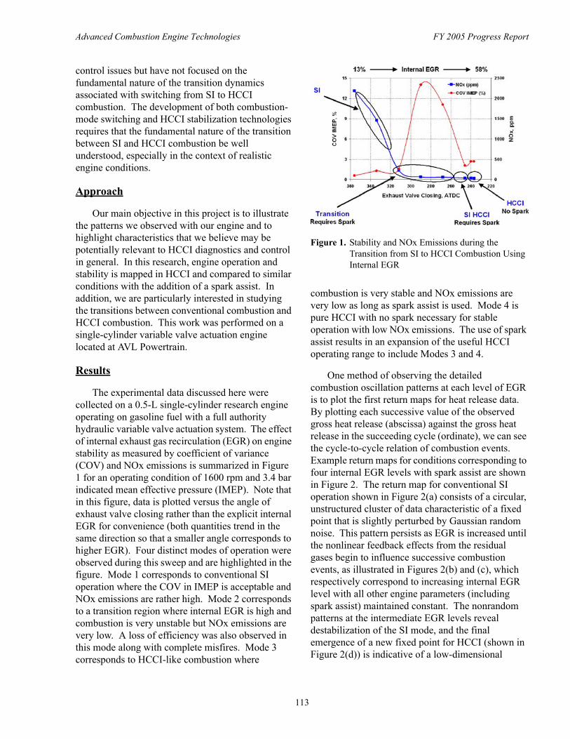
Advanced Combustion Engine Technologies FY 2005 Progress Report
control issues but have not focused on the fundamental nature of the transition dynamics associated with switching from SI to HCCI combustion. The development of both combustion-mode switching and HCCI stabilization technologies requires that the fundamental nature of the transition between SI and HCCI combustion be well understood, especially in the context of realistic engine conditions.
Approach
Our main objective in this project is to illustrate the patterns we observed with our engine and to highlight characteristics that we believe may be potentially relevant to HCCI diagnostics and control in general. In this research, engine operation and stability is mapped in HCCI and compared to similar conditions with the addition of a spark assist. In addition, we are particularly interested in studying the transitions between conventional combustion and HCCI combustion. This work was performed on a single-cylinder variable valve actuation engine located at AVL Powertrain.
Results
The experimental data discussed here were collected on a 0.5-L single-cylinder research engine operating on gasoline fuel with a full authority hydraulic variable valve actuation system. The effect of internal exhaust gas recirculation (EGR) on engine stability as measured by coefficient of variance (COV) and NOx emissions is summarized in Figure 1 for an operating condition of 1600 rpm and 3.4 bar indicated mean effective pressure (IMEP). Note that in this figure, data is plotted versus the angle of exhaust valve closing rather than the explicit internal EGR for convenience (both quantities trend in the same direction so that a smaller angle corresponds to higher EGR). Four distinct modes of operation were observed during this sweep and are highlighted in the figure. Mode 1 corresponds to conventional SI operation where the COV in IMEP is acceptable and NOx emissions are rather high. Mode 2 corresponds to a transition region where internal EGR is high and combustion is very unstable but NOx emissions are very low. A loss of efficiency was also observed in this mode along with complete misfires. Mode 3 corresponds to HCCI-like combustion where
Figure 1. Stability and NOx Emissions during the Transition from SI to HCCI Combustion Using Internal EGR
combustion is very stable and NOx emissions are very low as long as spark assist is used. Mode 4 is pure HCCI with no spark necessary for stable operation with low NOx emissions. The use of spark assist results in an expansion of the useful HCCI operating range to include Modes 3 and 4.
One method of observing the detailed combustion oscillation patterns at each level of EGR is to plot the first return maps for heat release data. By plotting each successive value of the observed gross heat release (abscissa) against the gross heat release in the succeeding cycle (ordinate), we can see the cycle-to-cycle relation of combustion events. Example return maps for conditions corresponding to four internal EGR levels with spark assist are shown in Figure 2. The return map for conventional SI operation shown in Figure 2(a) consists of a circular, unstructured cluster of data characteristic of a fixed point that is slightly perturbed by Gaussian random noise. This pattern persists as EGR is increased until the nonlinear feedback effects from the residual gases begin to influence successive combustion events, as illustrated in Figures 2(b) and (c), which respectively correspond to increasing internal EGR level with all other engine parameters (including spark assist) maintained constant. The nonrandom patterns at the intermediate EGR levels reveal destabilization of the SI mode, and the final emergence of a new fixed point for HCCI (shown in Figure 2(d)) is indicative of a low-dimensional
113
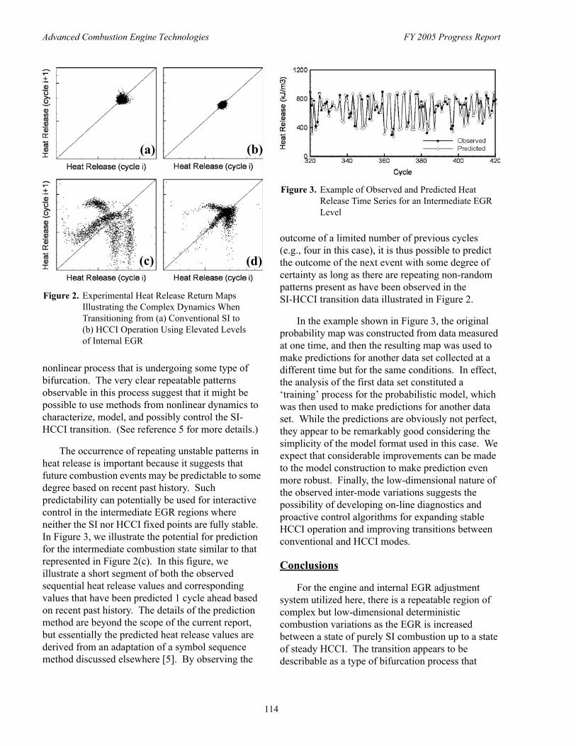
Advanced Combustion Engine Technologies FY 2005 Progress Report
(a) (b)
(c) (d)
Figure 2. Experimental Heat Release Return Maps Illustrating the Complex Dynamics When Transitioning from (a) Conventional SI to (b) HCCI Operation Using Elevated Levels of Internal EGR
nonlinear process that is undergoing some type of bifurcation. The very clear repeatable patterns observable in this process suggest that it might be possible to use methods from nonlinear dynamics to characterize, model, and possibly control the SIHCCI transition. (See reference 5 for more details.)
The occurrence of repeating unstable patterns in heat release is important because it suggests that future combustion events may be predictable to some degree based on recent past history. Such predictability can potentially be used for interactive control in the intermediate EGR regions where neither the SI nor HCCI fixed points are fully stable. In Figure 3, we illustrate the potential for prediction for the intermediate combustion state similar to that represented in Figure 2(c). In this figure, we illustrate a short segment of both the observed sequential heat release values and corresponding values that have been predicted 1 cycle ahead based on recent past history. The details of the prediction method are beyond the scope of the current report, but essentially the predicted heat release values are derived from an adaptation of a symbol sequence method discussed elsewhere [5]. By observing the
Figure 3. Example of Observed and Predicted Heat Release Time Series for an Intermediate EGR Level
outcome of a limited number of previous cycles (e.g., four in this case), it is thus possible to predict the outcome of the next event with some degree of certainty as long as there are repeating non-random patterns present as have been observed in the SI-HCCI transition data illustrated in Figure 2.
In the example shown in Figure 3, the original probability map was constructed from data measured at one time, and then the resulting map was used to make predictions for another data set collected at a different time but for the same conditions. In effect, the analysis of the first data set constituted a ‘training’ process for the probabilistic model, which was then used to make predictions for another data set. While the predictions are obviously not perfect, they appear to be remarkably good considering the simplicity of the model format used in this case. We expect that considerable improvements can be made to the model construction to make prediction even more robust. Finally, the low-dimensional nature of the observed inter-mode variations suggests the possibility of developing on-line diagnostics and proactive control algorithms for expanding stable HCCI operation and improving transitions between conventional and HCCI modes.
Conclusions
For the engine and internal EGR adjustment system utilized here, there is a repeatable region of complex but low-dimensional deterministic combustion variations as the EGR is increased between a state of purely SI combustion up to a state of steady HCCI. The transition appears to be describable as a type of bifurcation process that
114
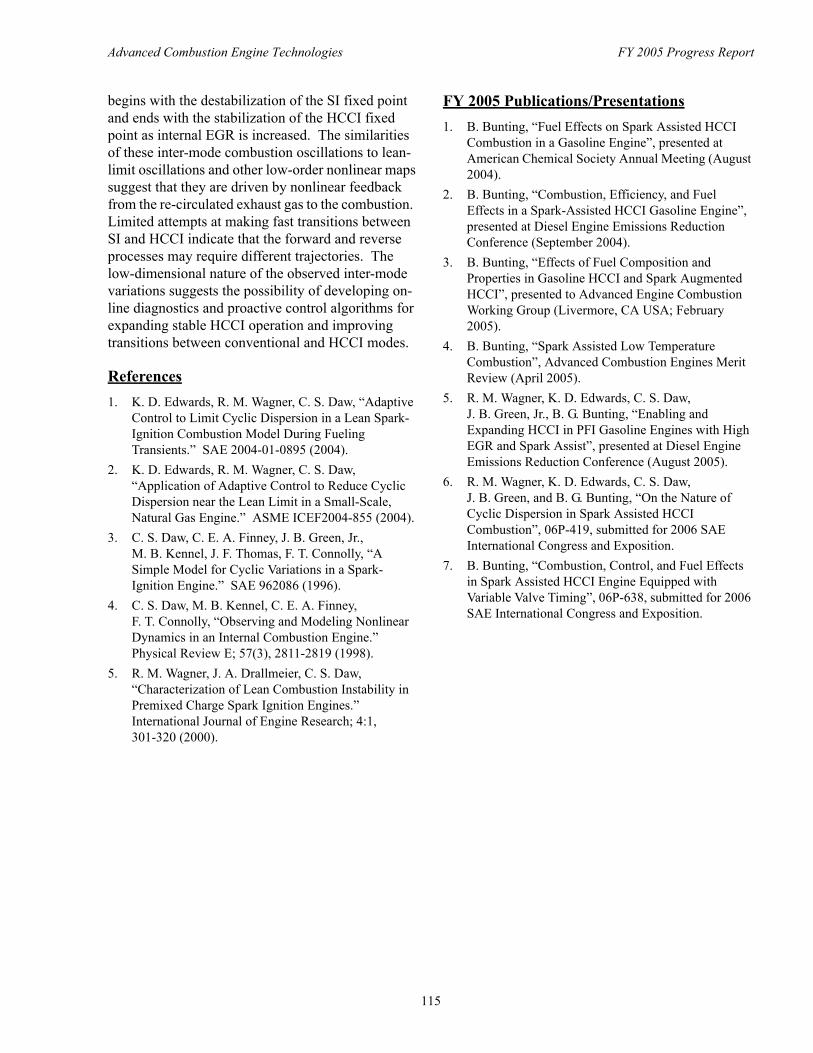
Advanced Combustion Engine Technologies FY 2005 Progress Report
begins with the destabilization of the SI fixed point and ends with the stabilization of the HCCI fixed point as internal EGR is increased. The similarities of these inter-mode combustion oscillations to lean-limit oscillations and other low-order nonlinear maps suggest that they are driven by nonlinear feedback from the re-circulated exhaust gas to the combustion. Limited attempts at making fast transitions between SI and HCCI indicate that the forward and reverse processes may require different trajectories. The low-dimensional nature of the observed inter-mode variations suggests the possibility of developing online diagnostics and proactive control algorithms for expanding stable HCCI operation and improving transitions between conventional and HCCI modes.
References 1. K. D. Edwards, R. M. Wagner, C. S. Daw, “Adaptive
Control to Limit Cyclic Dispersion in a Lean Spark-Ignition Combustion Model During Fueling Transients.” SAE 2004-01-0895 (2004).
2. K. D. Edwards, R. M. Wagner, C. S. Daw, “Application of Adaptive Control to Reduce Cyclic Dispersion near the Lean Limit in a Small-Scale, Natural Gas Engine.” ASME ICEF2004-855 (2004).
3. C. S. Daw, C. E. A. Finney, J. B. Green, Jr., M. B. Kennel, J. F. Thomas, F. T. Connolly, “A Simple Model for Cyclic Variations in a Spark-Ignition Engine.” SAE 962086 (1996).
4. C. S. Daw, M. B. Kennel, C. E. A. Finney, F. T. Connolly, “Observing and Modeling Nonlinear Dynamics in an Internal Combustion Engine.” Physical Review E; 57(3), 2811-2819 (1998).
5. R. M. Wagner, J. A. Drallmeier, C. S. Daw, “Characterization of Lean Combustion Instability in Premixed Charge Spark Ignition Engines.” International Journal of Engine Research; 4:1, 301-320 (2000).
FY 2005 Publications/Presentations 1. B. Bunting, “Fuel Effects on Spark Assisted HCCI
Combustion in a Gasoline Engine”, presented at American Chemical Society Annual Meeting (August 2004).
2. B. Bunting, “Combustion, Efficiency, and Fuel Effects in a Spark-Assisted HCCI Gasoline Engine”, presented at Diesel Engine Emissions Reduction Conference (September 2004).
3. B. Bunting, “Effects of Fuel Composition and Properties in Gasoline HCCI and Spark Augmented HCCI”, presented to Advanced Engine Combustion Working Group (Livermore, CA USA; February 2005).
4. B. Bunting, “Spark Assisted Low Temperature Combustion”, Advanced Combustion Engines Merit Review (April 2005).
5. R. M. Wagner, K. D. Edwards, C. S. Daw, J. B. Green, Jr., B. G. Bunting, “Enabling and Expanding HCCI in PFI Gasoline Engines with High EGR and Spark Assist”, presented at Diesel Engine Emissions Reduction Conference (August 2005).
6. R. M. Wagner, K. D. Edwards, C. S. Daw, J. B. Green, and B. G. Bunting, “On the Nature of Cyclic Dispersion in Spark Assisted HCCI Combustion”, 06P-419, submitted for 2006 SAE International Congress and Exposition.
7. B. Bunting, “Combustion, Control, and Fuel Effects in Spark Assisted HCCI Engine Equipped with Variable Valve Timing”, 06P-638, submitted for 2006 SAE International Congress and Exposition.
115
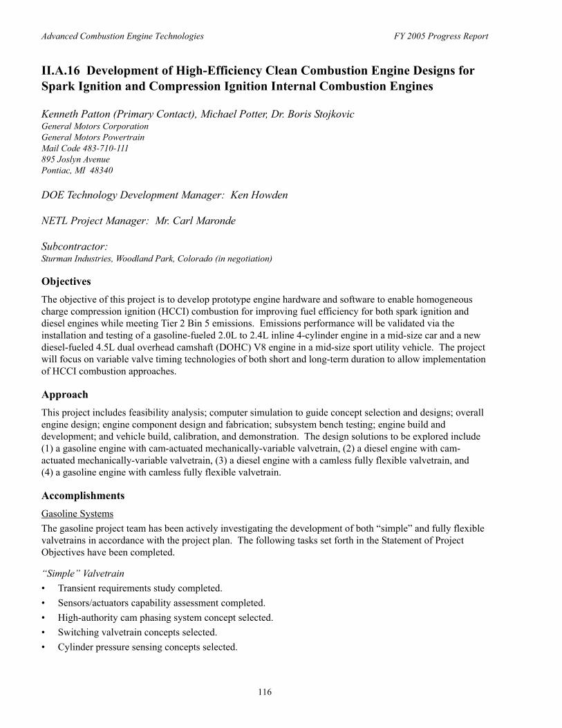
Advanced Combustion Engine Technologies FY 2005 Progress Report
II.A.16 Development of High-Efficiency Clean Combustion Engine Designs for Spark Ignition and Compression Ignition Internal Combustion Engines
Kenneth Patton (Primary Contact), Michael Potter, Dr. Boris Stojkovic General Motors Corporation General Motors Powertrain Mail Code 483-710-111 895 Joslyn Avenue Pontiac, MI 48340
DOE Technology Development Manager: Ken Howden
NETL Project Manager: Mr. Carl Maronde
Subcontractor:Sturman Industries, Woodland Park, Colorado (in negotiation)
Objectives The objective of this project is to develop prototype engine hardware and software to enable homogeneous charge compression ignition (HCCI) combustion for improving fuel efficiency for both spark ignition and diesel engines while meeting Tier 2 Bin 5 emissions. Emissions performance will be validated via the installation and testing of a gasoline-fueled 2.0L to 2.4L inline 4-cylinder engine in a mid-size car and a new diesel-fueled 4.5L dual overhead camshaft (DOHC) V8 engine in a mid-size sport utility vehicle. The project will focus on variable valve timing technologies of both short and long-term duration to allow implementation of HCCI combustion approaches.
Approach This project includes feasibility analysis; computer simulation to guide concept selection and designs; overall engine design; engine component design and fabrication; subsystem bench testing; engine build and development; and vehicle build, calibration, and demonstration. The design solutions to be explored include (1) a gasoline engine with cam-actuated mechanically-variable valvetrain, (2) a diesel engine with cam-actuated mechanically-variable valvetrain, (3) a diesel engine with a camless fully flexible valvetrain, and (4) a gasoline engine with camless fully flexible valvetrain.
Accomplishments Gasoline Systems The gasoline project team has been actively investigating the development of both “simple” and fully flexible valvetrains in accordance with the project plan. The following tasks set forth in the Statement of Project Objectives have been completed.
“Simple” Valvetrain • Transient requirements study completed. • Sensors/actuators capability assessment completed. • High-authority cam phasing system concept selected. • Switching valvetrain concepts selected. • Cylinder pressure sensing concepts selected.
116
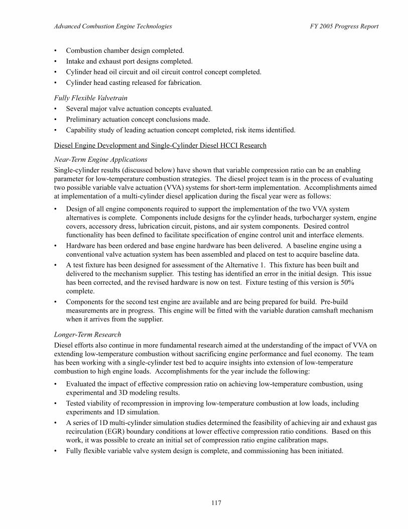
Advanced Combustion Engine Technologies FY 2005 Progress Report
• Combustion chamber design completed. • Intake and exhaust port designs completed. • Cylinder head oil circuit and oil circuit control concept completed. • Cylinder head casting released for fabrication.
Fully Flexible Valvetrain • Several major valve actuation concepts evaluated. • Preliminary actuation concept conclusions made. • Capability study of leading actuation concept completed, risk items identified.
Diesel Engine Development and Single-Cylinder Diesel HCCI Research
Near-Term Engine Applications Single-cylinder results (discussed below) have shown that variable compression ratio can be an enabling parameter for low-temperature combustion strategies. The diesel project team is in the process of evaluating two possible variable valve actuation (VVA) systems for short-term implementation. Accomplishments aimed at implementation of a multi-cylinder diesel application during the fiscal year were as follows:
• Design of all engine components required to support the implementation of the two VVA system alternatives is complete. Components include designs for the cylinder heads, turbocharger system, engine covers, accessory dress, lubrication circuit, pistons, and air system components. Desired control functionality has been defined to facilitate specification of engine control unit and interface elements.
• Hardware has been ordered and base engine hardware has been delivered. A baseline engine using a conventional valve actuation system has been assembled and placed on test to acquire baseline data.
• A test fixture has been designed for assessment of the Alternative 1. This fixture has been built and delivered to the mechanism supplier. This testing has identified an error in the initial design. This issue has been corrected, and the revised hardware is now on test. Fixture testing of this version is 50% complete.
• Components for the second test engine are available and are being prepared for build. Pre-build measurements are in progress. This engine will be fitted with the variable duration camshaft mechanism when it arrives from the supplier.
Longer-Term Research Diesel efforts also continue in more fundamental research aimed at the understanding of the impact of VVA on extending low-temperature combustion without sacrificing engine performance and fuel economy. The team has been working with a single-cylinder test bed to acquire insights into extension of low-temperature combustion to high engine loads. Accomplishments for the year include the following:
• Evaluated the impact of effective compression ratio on achieving low-temperature combustion, using experimental and 3D modeling results.
• Tested viability of recompression in improving low-temperature combustion at low loads, including experiments and 1D simulation.
• A series of 1D multi-cylinder simulation studies determined the feasibility of achieving air and exhaust gas recirculation (EGR) boundary conditions at lower effective compression ratio conditions. Based on this work, it was possible to create an initial set of compression ratio engine calibration maps.
• Fully flexible variable valve system design is complete, and commissioning has been initiated.
117
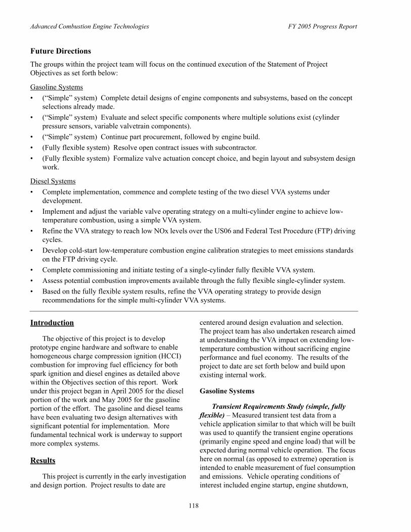
Advanced Combustion Engine Technologies FY 2005 Progress Report
Future Directions The groups within the project team will focus on the continued execution of the Statement of Project Objectives as set forth below:
Gasoline Systems • (“Simple” system) Complete detail designs of engine components and subsystems, based on the concept
selections already made. • (“Simple” system) Evaluate and select specific components where multiple solutions exist (cylinder
pressure sensors, variable valvetrain components). • (“Simple” system) Continue part procurement, followed by engine build. • (Fully flexible system) Resolve open contract issues with subcontractor. • (Fully flexible system) Formalize valve actuation concept choice, and begin layout and subsystem design
work.
Diesel Systems • Complete implementation, commence and complete testing of the two diesel VVA systems under
development. • Implement and adjust the variable valve operating strategy on a multi-cylinder engine to achieve low-
temperature combustion, using a simple VVA system. • Refine the VVA strategy to reach low NOx levels over the US06 and Federal Test Procedure (FTP) driving
cycles. • Develop cold-start low-temperature combustion engine calibration strategies to meet emissions standards
on the FTP driving cycle. • Complete commissioning and initiate testing of a single-cylinder fully flexible VVA system. • Assess potential combustion improvements available through the fully flexible single-cylinder system. • Based on the fully flexible system results, refine the VVA operating strategy to provide design
recommendations for the simple multi-cylinder VVA systems.
Introduction
The objective of this project is to develop prototype engine hardware and software to enable homogeneous charge compression ignition (HCCI) combustion for improving fuel efficiency for both spark ignition and diesel engines as detailed above within the Objectives section of this report. Work under this project began in April 2005 for the diesel portion of the work and May 2005 for the gasoline portion of the effort. The gasoline and diesel teams have been evaluating two design alternatives with significant potential for implementation. More fundamental technical work is underway to support more complex systems.
Results
This project is currently in the early investigation and design portion. Project results to date are
centered around design evaluation and selection. The project team has also undertaken research aimed at understanding the VVA impact on extending low-temperature combustion without sacrificing engine performance and fuel economy. The results of the project to date are set forth below and build upon existing internal work.
Gasoline Systems
Transient Requirements Study (simple, fully flexible) – Measured transient test data from a vehicle application similar to that which will be built was used to quantify the transient engine operations (primarily engine speed and engine load) that will be expected during normal vehicle operation. The focus here on normal (as opposed to extreme) operation is intended to enable measurement of fuel consumption and emissions. Vehicle operating conditions of interest included engine startup, engine shutdown,
118
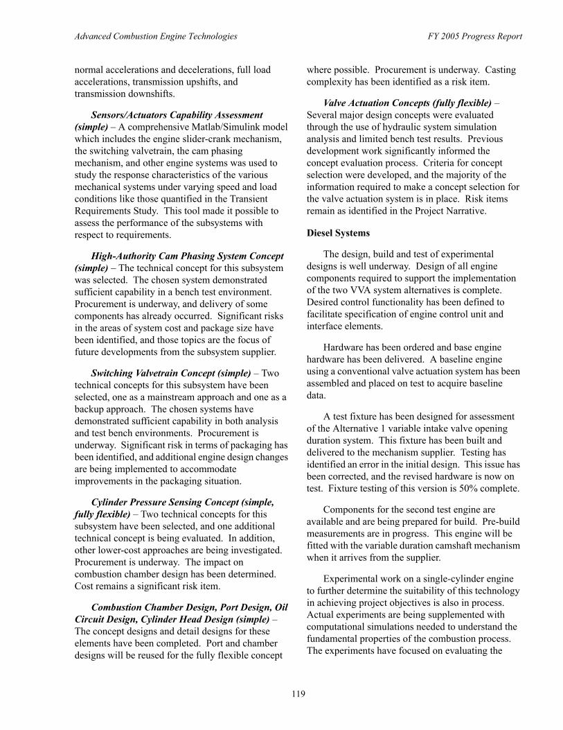
Advanced Combustion Engine Technologies FY 2005 Progress Report
normal accelerations and decelerations, full load accelerations, transmission upshifts, and transmission downshifts.
Sensors/Actuators Capability Assessment (simple) – A comprehensive Matlab/Simulink model which includes the engine slider-crank mechanism, the switching valvetrain, the cam phasing mechanism, and other engine systems was used to study the response characteristics of the various mechanical systems under varying speed and load conditions like those quantified in the Transient Requirements Study. This tool made it possible to assess the performance of the subsystems with respect to requirements.
High-Authority Cam Phasing System Concept (simple) – The technical concept for this subsystem was selected. The chosen system demonstrated sufficient capability in a bench test environment. Procurement is underway, and delivery of some components has already occurred. Significant risks in the areas of system cost and package size have been identified, and those topics are the focus of future developments from the subsystem supplier.
Switching Valvetrain Concept (simple) – Two technical concepts for this subsystem have been selected, one as a mainstream approach and one as a backup approach. The chosen systems have demonstrated sufficient capability in both analysis and test bench environments. Procurement is underway. Significant risk in terms of packaging has been identified, and additional engine design changes are being implemented to accommodate improvements in the packaging situation.
Cylinder Pressure Sensing Concept (simple, fully flexible) – Two technical concepts for this subsystem have been selected, and one additional technical concept is being evaluated. In addition, other lower-cost approaches are being investigated. Procurement is underway. The impact on combustion chamber design has been determined. Cost remains a significant risk item.
Combustion Chamber Design, Port Design, Oil Circuit Design, Cylinder Head Design (simple) – The concept designs and detail designs for these elements have been completed. Port and chamber designs will be reused for the fully flexible concept
where possible. Procurement is underway. Casting complexity has been identified as a risk item.
Valve Actuation Concepts (fully flexible) – Several major design concepts were evaluated through the use of hydraulic system simulation analysis and limited bench test results. Previous development work significantly informed the concept evaluation process. Criteria for concept selection were developed, and the majority of the information required to make a concept selection for the valve actuation system is in place. Risk items remain as identified in the Project Narrative.
Diesel Systems
The design, build and test of experimental designs is well underway. Design of all engine components required to support the implementation of the two VVA system alternatives is complete. Desired control functionality has been defined to facilitate specification of engine control unit and interface elements.
Hardware has been ordered and base engine hardware has been delivered. A baseline engine using a conventional valve actuation system has been assembled and placed on test to acquire baseline data.
A test fixture has been designed for assessment of the Alternative 1 variable intake valve opening duration system. This fixture has been built and delivered to the mechanism supplier. Testing has identified an error in the initial design. This issue has been corrected, and the revised hardware is now on test. Fixture testing of this version is 50% complete.
Components for the second test engine are available and are being prepared for build. Pre-build measurements are in progress. This engine will be fitted with the variable duration camshaft mechanism when it arrives from the supplier.
Experimental work on a single-cylinder engine to further determine the suitability of this technology in achieving project objectives is also in process. Actual experiments are being supplemented with computational simulations needed to understand the fundamental properties of the combustion process. The experiments have focused on evaluating the
119
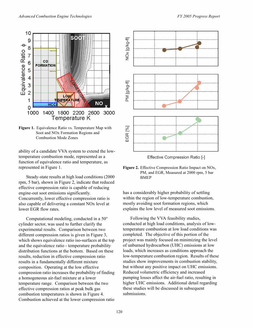
Advanced Combustion Engine Technologies FY 2005 Progress Report
Figure 1. Equivalence Ratio vs. Temperature Map with Soot and NOx Formation Regions and Combustion Mode Zones
ability of a candidate VVA system to extend the low-temperature combustion mode, represented as a function of equivalence ratio and temperature, as represented in Figure 1.
Steady-state results at high load conditions (2000 rpm, 5 bar), shown in Figure 2, indicate that reduced effective compression ratio is capable of reducing engine-out soot emissions significantly. Concurrently, lower effective compression ratio is also capable of delivering a constant NOx level at lower EGR flow rates.
Computational modeling, conducted in a 50° cylinder sector, was used to further clarify the experimental results. Comparison between two different compression ratios is given in Figure 3, which shows equivalence ratio iso-surfaces at the top and the equivalence ratio - temperature probability distribution functions at the bottom. Based on these results, reduction in effective compression ratio results in a fundamentally different mixture composition. Operating at the low effective compression ratio increases the probability of finding a homogeneous air-fuel mixture at a lower temperature range. Comparison between the two effective compression ratios at peak bulk gas combustion temperatures is shown in Figure 4. Combustion achieved at the lower compression ratio
Figure 2. Effective Compression Ratio Impact on NOx, PM, and EGR, Measured at 2000 rpm, 5 bar BMEP
has a considerably higher probability of settling within the region of low-temperature combustion, mostly avoiding soot formation regions, which explains the low level of measured soot emissions.
Following the VVA feasibility studies, conducted at high load conditions, analysis of low-temperature combustion at low load conditions was completed. The objective of this portion of the project was mainly focused on minimizing the level of unburned hydrocarbon (UHC) emissions at low loads, which increases as conditions approach the low-temperature combustion region. Results of these studies show improvements in combustion stability, but without any positive impact on UHC emissions. Reduced volumetric efficiency and increased pumping losses affect the air-fuel ratio, resulting in higher UHC emissions. Additional detail regarding these studies will be discussed in subsequent submissions.
120
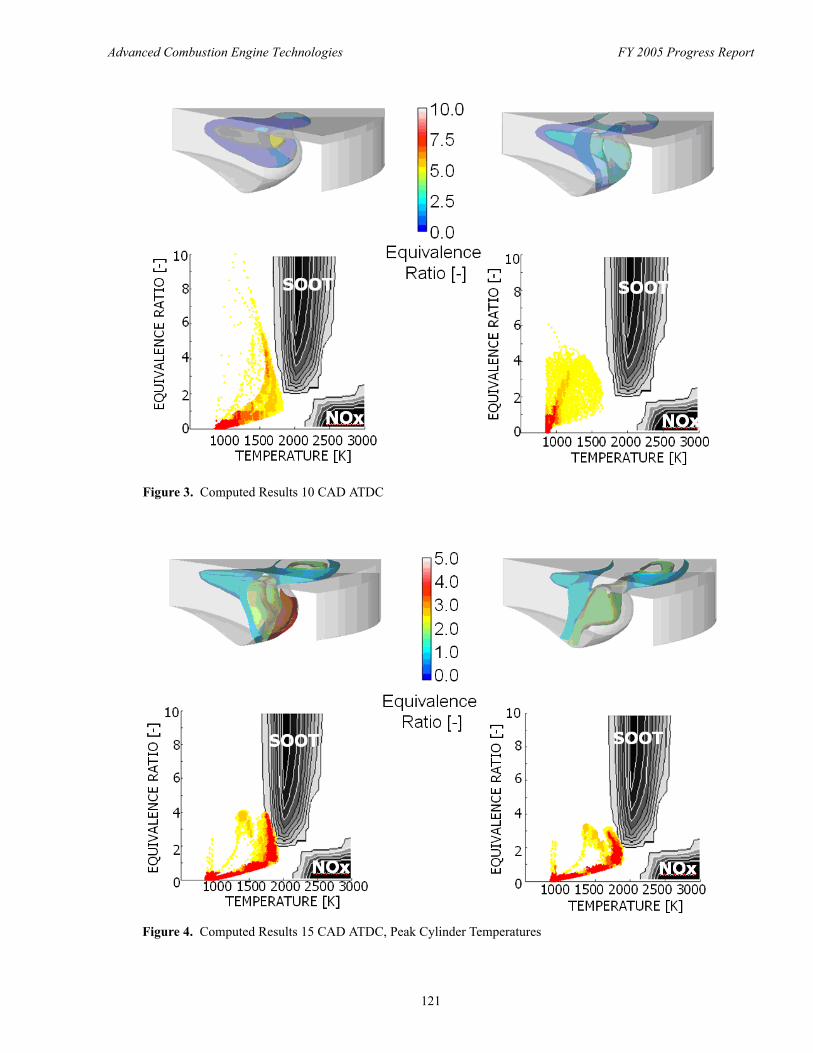
Advanced Combustion Engine Technologies FY 2005 Progress Report
Figure 3. Computed Results 10 CAD ATDC
Figure 4. Computed Results 15 CAD ATDC, Peak Cylinder Temperatures
121
Advanced Combustion Engine Technologies FY 2005 Progress Report
Conclusions
This project is well underway and on track to meet the objective of developing prototype engine hardware and software to enable homogeneous charge compression ignition (HCCI) combustion. Future reports will set forth the results of this continued development, as well as the results of useful experimentation and computational models being refined under the project.
122
Advanced Combustion Engine Technologies FY 2005 Progress Report
II.A.17 KIVA-4 Development
David J. Torres Theoretical Division, Group T-3, MS B216 Los Alamos National Laboratory Los Alamos, NM 87544
DOE Technology Development Manager: Kevin Stork
Objectives • Investigate ways of constructing structured and unstructured KIVA-4 meshes that accommodate moving
boundaries. • Parallelize KIVA-4 so the code can run on multiple computers simultaneously. • Continue to validate KIVA-4 against exact solutions.
Approach • Develop a mesh converter that converts structured KIVA-3V meshes to compatible KIVA-4 meshes. • Pursue two strategies for constructing unstructured meshes. The first strategy uses only one mesh for the
entire engine cycle. The second strategy uses multiple meshes and maps variables from one mesh to the other at specified times.
• Implement improved mesh movement algorithms into KIVA-4. • Employ the Message-Passing Interface (MPI) libraries to perform the parallelization of KIVA-4. Test the
parallelization. • Use a variety of exact solutions to the Navier-Stokes equations governing fluid flow to test the accuracy of
KIVA-4.
Accomplishments • Progress has been made in supplementing KIVA-4 with grid-generation and grid-movement capability.
– The KIVA-3V to KIVA-4 mesh converter was developed and used to test several structured engine geometries.
– A grid-generation code was developed to construct an unstructured hexahedral grid with vertical ports which would be used for an entire engine cycle.
– Software to map cell-centered variables from one unstructured mesh to another was developed. – Improved mesh movement algorithms were implemented into KIVA-4.
• KIVA-4 was parallelized with MPI (except for spray injection and mesh snapping). Spray injection and secondary subroutines that govern mesh changes (mesh snapping) still need to be parallelized. However, parallel 3D engine calculations without spray can now be performed with KIVA-4. Tests proved that the same computational results are achieved regardless of the number of processors used. Parallel KIVA-4 runs many times faster (see Table 1).
• KIVA-4 has been validated against several exact solutions. These solutions include mass diffusion, density advection, velocity advection, shock propagation, compression tests, and the driven cavity problem.
123
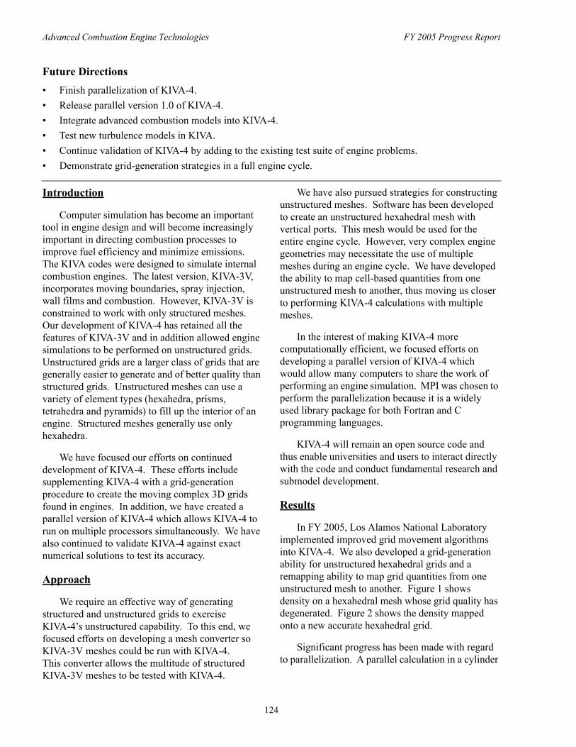
Advanced Combustion Engine Technologies FY 2005 Progress Report
Future Directions • Finish parallelization of KIVA-4. • Release parallel version 1.0 of KIVA-4. • Integrate advanced combustion models into KIVA-4. • Test new turbulence models in KIVA. • Continue validation of KIVA-4 by adding to the existing test suite of engine problems. • Demonstrate grid-generation strategies in a full engine cycle.
Introduction
Computer simulation has become an important tool in engine design and will become increasingly important in directing combustion processes to improve fuel efficiency and minimize emissions. The KIVA codes were designed to simulate internal combustion engines. The latest version, KIVA-3V, incorporates moving boundaries, spray injection, wall films and combustion. However, KIVA-3V is constrained to work with only structured meshes. Our development of KIVA-4 has retained all the features of KIVA-3V and in addition allowed engine simulations to be performed on unstructured grids. Unstructured grids are a larger class of grids that are generally easier to generate and of better quality than structured grids. Unstructured meshes can use a variety of element types (hexahedra, prisms, tetrahedra and pyramids) to fill up the interior of an engine. Structured meshes generally use only hexahedra.
We have focused our efforts on continued development of KIVA-4. These efforts include supplementing KIVA-4 with a grid-generation procedure to create the moving complex 3D grids found in engines. In addition, we have created a parallel version of KIVA-4 which allows KIVA-4 to run on multiple processors simultaneously. We have also continued to validate KIVA-4 against exact numerical solutions to test its accuracy.
Approach
We require an effective way of generating structured and unstructured grids to exercise KIVA-4’s unstructured capability. To this end, we focused efforts on developing a mesh converter so KIVA-3V meshes could be run with KIVA-4. This converter allows the multitude of structured KIVA-3V meshes to be tested with KIVA-4.
We have also pursued strategies for constructing unstructured meshes. Software has been developed to create an unstructured hexahedral mesh with vertical ports. This mesh would be used for the entire engine cycle. However, very complex engine geometries may necessitate the use of multiple meshes during an engine cycle. We have developed the ability to map cell-based quantities from one unstructured mesh to another, thus moving us closer to performing KIVA-4 calculations with multiple meshes.
In the interest of making KIVA-4 more computationally efficient, we focused efforts on developing a parallel version of KIVA-4 which would allow many computers to share the work of performing an engine simulation. MPI was chosen to perform the parallelization because it is a widely used library package for both Fortran and C programming languages.
KIVA-4 will remain an open source code and thus enable universities and users to interact directly with the code and conduct fundamental research and submodel development.
Results
In FY 2005, Los Alamos National Laboratory implemented improved grid movement algorithms into KIVA-4. We also developed a grid-generation ability for unstructured hexahedral grids and a remapping ability to map grid quantities from one unstructured mesh to another. Figure 1 shows density on a hexahedral mesh whose grid quality has degenerated. Figure 2 shows the density mapped onto a new accurate hexahedral grid.
Significant progress has been made with regard to parallelization. A parallel calculation in a cylinder
124
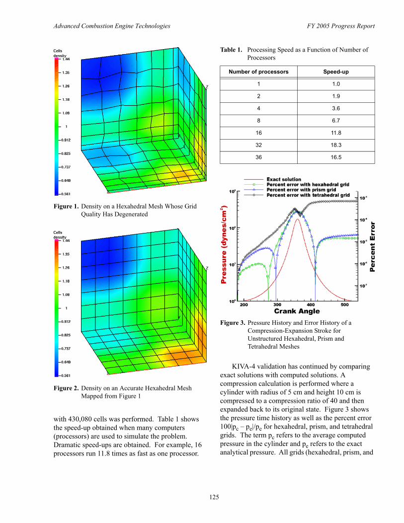
Advanced Combustion Engine Technologies FY 2005 Progress Report
Table 1. Processing Speed as a Function of Number of Processors
Figure 1. Density on a Hexahedral Mesh Whose Grid Quality Has Degenerated
Number of processors Speed-up
1 1.0
2 1.9
4 3.6
8 6.7
16 11.8
32 18.3
36 16.5
Figure 2. Density on an Accurate Hexahedral Mesh Mapped from Figure 1
Figure 3. Pressure History and Error History of a Compression-Expansion Stroke for Unstructured Hexahedral, Prism and Tetrahedral Meshes
KIVA-4 validation has continued by comparing exact solutions with computed solutions. A compression calculation is performed where a cylinder with radius of 5 cm and height 10 cm is compressed to a compression ratio of 40 and then expanded back to its original state. Figure 3 shows
with 430,080 cells was performed. Table 1 shows the pressure time history as well as the percent error the speed-up obtained when many computers 100|pc – pe|/pe for hexahedral, prism, and tetrahedral (processors) are used to simulate the problem. grids. The term pc refers to the average computed Dramatic speed-ups are obtained. For example, 16 pressure in the cylinder and pe refers to the exact processors run 11.8 times as fast as one processor. analytical pressure. All grids (hexahedral, prism, and
125
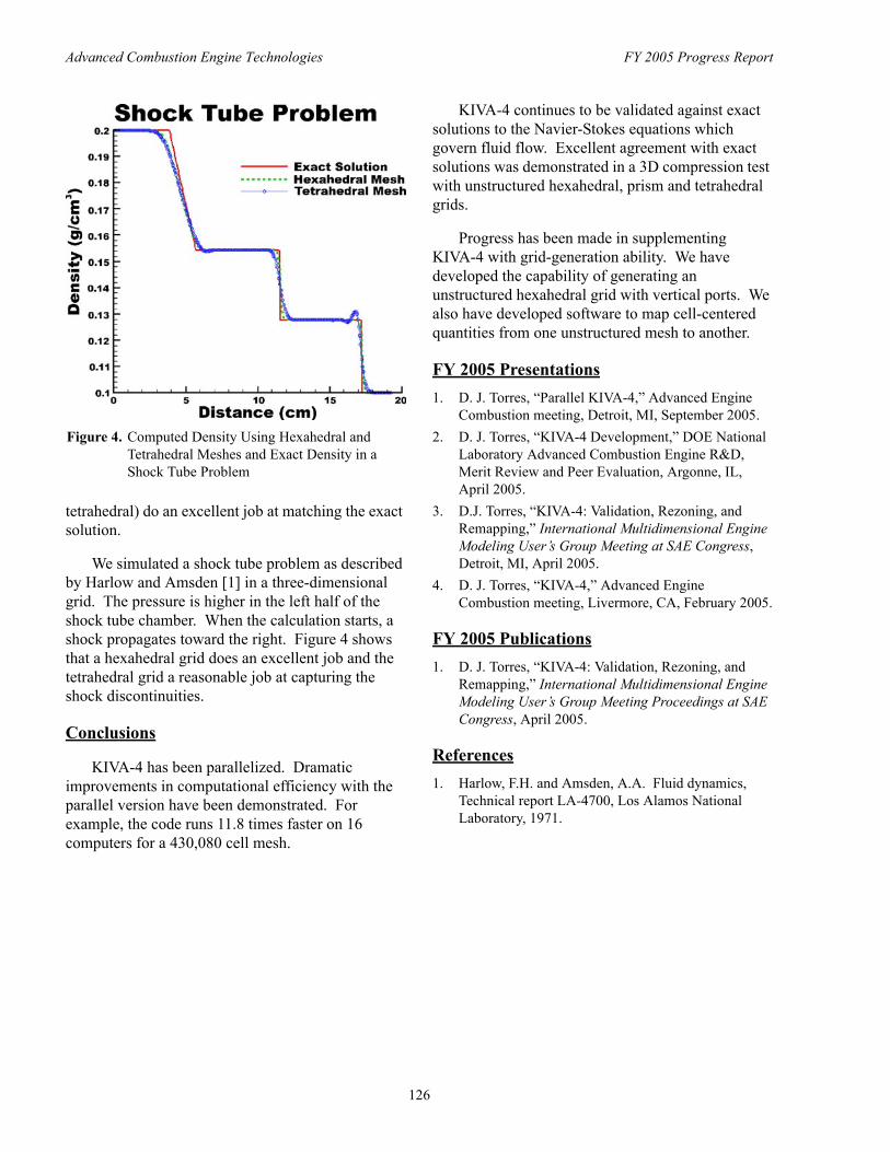
Advanced Combustion Engine Technologies FY 2005 Progress Report
Figure 4. Computed Density Using Hexahedral and Tetrahedral Meshes and Exact Density in a Shock Tube Problem
tetrahedral) do an excellent job at matching the exact solution.
We simulated a shock tube problem as described by Harlow and Amsden [1] in a three-dimensional grid. The pressure is higher in the left half of the shock tube chamber. When the calculation starts, a shock propagates toward the right. Figure 4 shows that a hexahedral grid does an excellent job and the tetrahedral grid a reasonable job at capturing the shock discontinuities.
Conclusions
KIVA-4 has been parallelized. Dramatic improvements in computational efficiency with the parallel version have been demonstrated. For example, the code runs 11.8 times faster on 16 computers for a 430,080 cell mesh.
KIVA-4 continues to be validated against exact solutions to the Navier-Stokes equations which govern fluid flow. Excellent agreement with exact solutions was demonstrated in a 3D compression test with unstructured hexahedral, prism and tetrahedral grids.
Progress has been made in supplementing KIVA-4 with grid-generation ability. We have developed the capability of generating an unstructured hexahedral grid with vertical ports. We also have developed software to map cell-centered quantities from one unstructured mesh to another.
FY 2005 Presentations 1. D. J. Torres, “Parallel KIVA-4,” Advanced Engine
Combustion meeting, Detroit, MI, September 2005. 2. D. J. Torres, “KIVA-4 Development,” DOE National
Laboratory Advanced Combustion Engine R&D, Merit Review and Peer Evaluation, Argonne, IL, April 2005.
3. D.J. Torres, “KIVA-4: Validation, Rezoning, and Remapping,” International Multidimensional Engine Modeling User’s Group Meeting at SAE Congress, Detroit, MI, April 2005.
4. D. J. Torres, “KIVA-4,” Advanced Engine Combustion meeting, Livermore, CA, February 2005.
FY 2005 Publications 1. D. J. Torres, “KIVA-4: Validation, Rezoning, and
Remapping,” International Multidimensional Engine Modeling User’s Group Meeting Proceedings at SAE Congress, April 2005.
References 1. Harlow, F.H. and Amsden, A.A. Fluid dynamics,
Technical report LA-4700, Los Alamos National Laboratory, 1971.
126
Advanced Combustion Engine Technologies FY 2005 Progress Report
II.A.18 Chemical Kinetic Modeling of Combustion of Automotive Fuels
William J. Pitz (Primary Contact), Charles K. Westbrook Lawrence Livermore National Laboratory P. O. Box 808, L-091 Livermore, CA 94551
DOE Technology Development Manager: Kevin Stork
Objectives • Develop detailed chemical kinetic reaction models for components of fuels, including oxygenated species
and additives used in diesel, spark-ignition and homogeneous charge compression ignition (HCCI) engines • Develop surrogate mixtures of hydrocarbon components to represent real fuels and lead to efficient
reduced combustion models • Characterize the role of fuel composition on production of emissions from practical automotive engines
Approach • Identify individual fuel components and their molecular structures • Develop kinetic reaction mechanisms for fuel components and additives • Compute ignition and flame structure for fuel components under diesel, spark-ignition and HCCI
conditions • Compute ignition and flame structure for surrogate mixtures of fuel components under diesel,
spark-ignition and HCCI conditions
Accomplishments • Completed models for chemical kinetics of combustion of two major fuel components, toluene and methyl
cyclohexane, and of an oxygenated diesel fuel additive, dimethyl carbonate • Continued development of surrogate mixtures to describe HCCI ignition • Identified specific chemical species contributing to problems in providing an optimal surrogate • Continued past studies of mechanisms by which oxygenated diesel fuel components reduce soot
production
Future Directions • Extend model capabilities to additional classes of fuel components • Continue development of increasingly complex surrogate fuel mixtures • Increase collaborations with programs outside Lawrence Livermore National Laboratory (LLNL) dealing
with automotive fuel issues
Introduction including n-paraffins, branched paraffins, cyclic and
Automotive hydrocarbon fuels consist of complex mixtures of hundreds or even thousands of different components. These components can be grouped into a number of structurally distinct classes,
branched cyclic paraffins, olefins, oxygenates, and aromatics (see Figure 1). The fractional amounts of these components are quite different in gasoline, diesel fuel and jet fuels, which contributes to the very
127
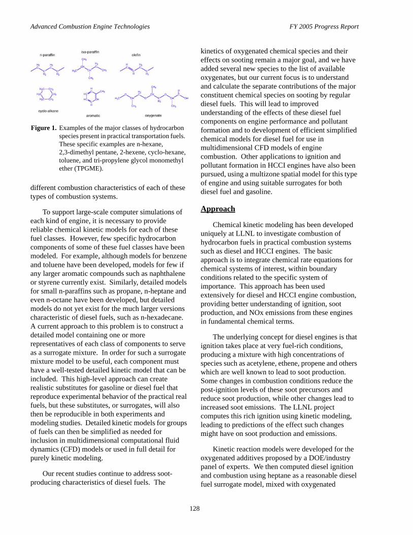
Advanced Combustion Engine Technologies FY 2005 Progress Report
Figure 1. Examples of the major classes of hydrocarbon species present in practical transportation fuels. These specific examples are n-hexane, 2,3-dimethyl pentane, 2-hexene, cyclo-hexane, toluene, and tri-propylene glycol monomethyl ether (TPGME).
different combustion characteristics of each of these types of combustion systems.
To support large-scale computer simulations of each kind of engine, it is necessary to provide reliable chemical kinetic models for each of these fuel classes. However, few specific hydrocarbon components of some of these fuel classes have been modeled. For example, although models for benzene and toluene have been developed, models for few if any larger aromatic compounds such as naphthalene or styrene currently exist. Similarly, detailed models for small n-paraffins such as propane, n-heptane and even n-octane have been developed, but detailed models do not yet exist for the much larger versions characteristic of diesel fuels, such as n-hexadecane. A current approach to this problem is to construct a detailed model containing one or more representatives of each class of components to serve as a surrogate mixture. In order for such a surrogate mixture model to be useful, each component must have a well-tested detailed kinetic model that can be included. This high-level approach can create realistic substitutes for gasoline or diesel fuel that reproduce experimental behavior of the practical real fuels, but these substitutes, or surrogates, will also then be reproducible in both experiments and modeling studies. Detailed kinetic models for groups of fuels can then be simplified as needed for inclusion in multidimensional computational fluid dynamics (CFD) models or used in full detail for purely kinetic modeling.
Our recent studies continue to address soot-producing characteristics of diesel fuels. The
kinetics of oxygenated chemical species and their effects on sooting remain a major goal, and we have added several new species to the list of available oxygenates, but our current focus is to understand and calculate the separate contributions of the major constituent chemical species on sooting by regular diesel fuels. This will lead to improved understanding of the effects of these diesel fuel components on engine performance and pollutant formation and to development of efficient simplified chemical models for diesel fuel for use in multidimensional CFD models of engine combustion. Other applications to ignition and pollutant formation in HCCI engines have also been pursued, using a multizone spatial model for this type of engine and using suitable surrogates for both diesel fuel and gasoline.
Approach
Chemical kinetic modeling has been developed uniquely at LLNL to investigate combustion of hydrocarbon fuels in practical combustion systems such as diesel and HCCI engines. The basic approach is to integrate chemical rate equations for chemical systems of interest, within boundary conditions related to the specific system of importance. This approach has been used extensively for diesel and HCCI engine combustion, providing better understanding of ignition, soot production, and NOx emissions from these engines in fundamental chemical terms.
The underlying concept for diesel engines is that ignition takes place at very fuel-rich conditions, producing a mixture with high concentrations of species such as acetylene, ethene, propene and others which are well known to lead to soot production. Some changes in combustion conditions reduce the post-ignition levels of these soot precursors and reduce soot production, while other changes lead to increased soot emissions. The LLNL project computes this rich ignition using kinetic modeling, leading to predictions of the effect such changes might have on soot production and emissions.
Kinetic reaction models were developed for the oxygenated additives proposed by a DOE/industry panel of experts. We then computed diesel ignition and combustion using heptane as a reasonable diesel fuel surrogate model, mixed with oxygenated
128
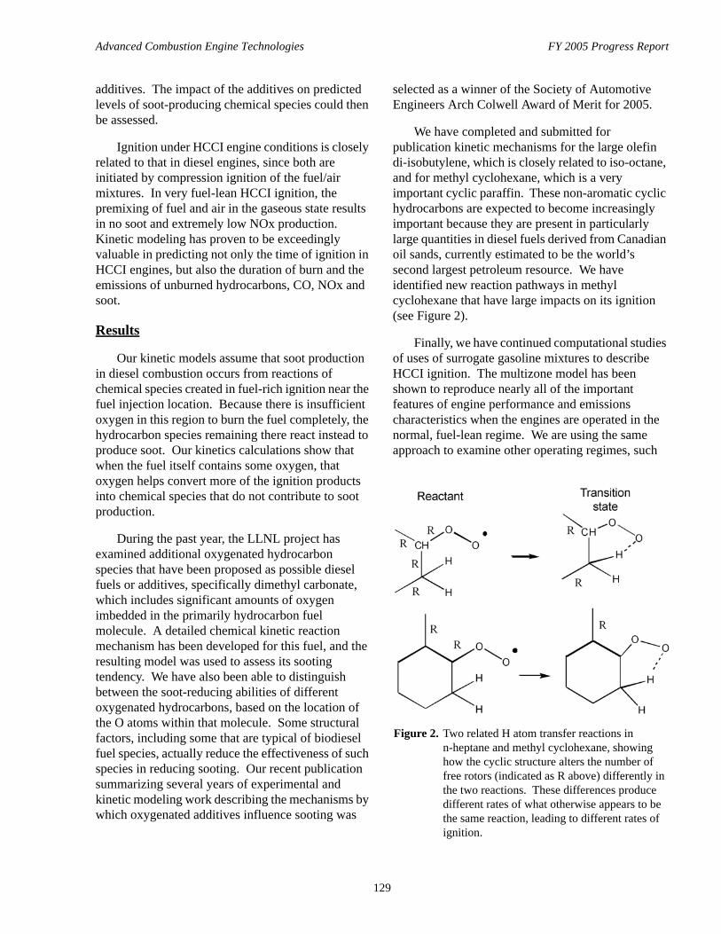
Advanced Combustion Engine Technologies FY 2005 Progress Report
additives. The impact of the additives on predicted levels of soot-producing chemical species could then be assessed.
Ignition under HCCI engine conditions is closely related to that in diesel engines, since both are initiated by compression ignition of the fuel/air mixtures. In very fuel-lean HCCI ignition, the premixing of fuel and air in the gaseous state results in no soot and extremely low NOx production. Kinetic modeling has proven to be exceedingly valuable in predicting not only the time of ignition in HCCI engines, but also the duration of burn and the emissions of unburned hydrocarbons, CO, NOx and soot.
Results
Our kinetic models assume that soot production in diesel combustion occurs from reactions of chemical species created in fuel-rich ignition near the fuel injection location. Because there is insufficient oxygen in this region to burn the fuel completely, the hydrocarbon species remaining there react instead to produce soot. Our kinetics calculations show that when the fuel itself contains some oxygen, that oxygen helps convert more of the ignition products into chemical species that do not contribute to soot production.
During the past year, the LLNL project has examined additional oxygenated hydrocarbon species that have been proposed as possible diesel fuels or additives, specifically dimethyl carbonate, which includes significant amounts of oxygen imbedded in the primarily hydrocarbon fuel molecule. A detailed chemical kinetic reaction mechanism has been developed for this fuel, and the resulting model was used to assess its sooting tendency. We have also been able to distinguish between the soot-reducing abilities of different oxygenated hydrocarbons, based on the location of the O atoms within that molecule. Some structural factors, including some that are typical of biodiesel fuel species, actually reduce the effectiveness of such species in reducing sooting. Our recent publication summarizing several years of experimental and kinetic modeling work describing the mechanisms by which oxygenated additives influence sooting was
selected as a winner of the Society of Automotive Engineers Arch Colwell Award of Merit for 2005.
We have completed and submitted for publication kinetic mechanisms for the large olefin di-isobutylene, which is closely related to iso-octane, and for methyl cyclohexane, which is a very important cyclic paraffin. These non-aromatic cyclic hydrocarbons are expected to become increasingly important because they are present in particularly large quantities in diesel fuels derived from Canadian oil sands, currently estimated to be the world’s second largest petroleum resource. We have identified new reaction pathways in methyl cyclohexane that have large impacts on its ignition (see Figure 2).
Finally, we have continued computational studies of uses of surrogate gasoline mixtures to describe HCCI ignition. The multizone model has been shown to reproduce nearly all of the important features of engine performance and emissions characteristics when the engines are operated in the normal, fuel-lean regime. We are using the same approach to examine other operating regimes, such
Figure 2. Two related H atom transfer reactions in n-heptane and methyl cyclohexane, showing how the cyclic structure alters the number of free rotors (indicated as R above) differently in the two reactions. These differences produce different rates of what otherwise appears to be the same reaction, leading to different rates of ignition.
129
Advanced Combustion Engine Technologies FY 2005 Progress Report
as operation with extensive amounts of exhaust gas recirculation or other forms of dilution but with richer fuel/air mixtures.
Conclusions
Kinetic modeling provides a unique tool to analyze combustion properties of diesel, spark-ignition and HCCI engines. A kinetic model can be very cost-effective as an alternative to extended experimental analyses and as guidance for more efficient experimentation, and computations can also provide a fundamental explanation of the reasons for the observed results. LLNL kinetic models are providing this valuable capability for engine research at many university and industrial facilities in the United States and are essential tools in engine research.
FY 2005 Publications/Presentations 1. Glaude, P.-A., Pitz, W.J., and Thomson, M.J.,
“Chemical Kinetic Modeling of Dimethyl Carbonate in an Opposed-Flow Diffusion Flame”, Proc. Combust. Inst. 30, 1111-1118 (2005).
2. Mueller, C.J., Pitz, W.J., Pickett, L.M., Martin, G.C., Siebers, D.L., and Westbrook, C.K., “Effects of Oxygenates on Soot Processes in DI Diesel Engines: Experiments and Numerical Simulations”, Society of Automotive Engineers SAE 2003-01-1791 (2003) and Japan Society of Automotive Engineers JSAE 20030193 (2003).
3. Westbrook, C.K., Mizobuchi, Y., Poinsot, T.J., Smith, P.J., and Warnatz, J., “Computational Combustion”, Proc. Combust. Inst. 30, 125-157 (2005).
4. Zheng, X., Lu, T.F., Law, C.K., and Westbrook, C.K., “Experimental and Computational Study of Non-Premixed Ignition of Dimethyl Ether”, Proc. Combust. Inst. 30, 1101-1109 (2005).
5. Naik, C.V., Pitz, W.J., Sjöberg, M., Dec, J.E., Orme, J., Curran, H.J., Simmie, J.M., and Westbrook, C.K., “Detailed Chemical Kinetic Modeling of Surrogate Fuels for Gasoline and Application to an HCCI Engine”, Society of Automotive Engineers publication SAE 2005-01-3741 (2005).
6. Naik, C.V., Pitz, W.J., Sjöberg, M., Dec, J.E., Orme, J., Curran, H.J., Simmie, J.M., and Westbrook, C.K., “Detailed Chemical Kinetic Modeling of Surrogate Fuels for Gasoline and Application to an HCCI Engine”, Joint Meeting of the US Sections of The Combustion Institute, Philadelphia, PA, March 2005.
7. Metcalfe, W., Curran, H.J., Simmie, J.M., Pitz, W.J., and Westbrook, C.K., “The Development of a Detailed Chemical Kinetic Mechanism for Diisobutylene and Comparison to Shock Tube Ignition Times”, Joint Meeting of the US Sections of The Combustion Institute, Philadelphia, PA, March 2005.
8. Curran, H.J., Jayaweera, T.M., Pitz, W.J., and Westbrook, C.K., “A Detailed Modeling Study of Propane Oxidation”, Western States Section meeting of The Combustion Institute, 2004.
9. Buchholz, B.A., Mueller, C.J., Upatnieks, A., Martin, G.C., Pitz, W.J., and Westbrook, C.K., “Using Carbon-14 Isotope Tracing to Investigate Molecular Structure Effects of the Oxygenate Dibutyl Maleate on Soot Emissions from a DI Diesel Engine”, Society of Automotive Engineers publication SAE 2004-011849 (2004).
10. Pitz, W.J., Naik, C.V., Mhaulduin, T.N., Westbrook, C.K., Curran, H.J., Orme, J.P., and Simmie, J.M., “Modeling and Experimental Investigation of Methylcyclohexane Ignition in a Rapid Compression Machine”, submitted to Thirty-First International Symposium on Combustion, 2005.
11. Silke, E.J., Curran, H.J., Simmie, J.M., Pitz, W.J., and Westbrook, C.K., “A Rapid Compression Machine Modelling Study of the Heptane Isomers”, European Combustion Meeting of The Combustion Institute, 2004.
12. Metcalfe, W.K., Pitz, W.J., Curran, H.J., Simmie, J.M., and Westbrook, C.K., “The Development of a Detailed Chemical Kinetic Mechanism for Di-isobutylene and Comparison to Shock Tube Ignition Times”, submitted to Thirty-First International Symposium on Combustion, 2005.
13. Westbrook, C.K., Pitz, W.J. and Curran, H.J., “A Chemical Kinetic Modeling Study of the Effects of Oxygenated Hydrocarbons on Soot Emissions from Diesel Engines”, submitted to Journal of Physical Chemistry A, 2005.
130
Advanced Combustion Engine Technologies FY 2005 Progress Report
II.A.19 Free Piston Engine Research
Peter Van Blarigan Sandia National Laboratories 7011 East Ave. Livermore, CA 94550
DOE Technology Development Manager: Kevin Stork
Objectives • Model the stability of electrically coupled opposed free pistons in a single-cylinder free-piston engine • Utilize computational fluid dynamics (CFD) modeling to design the inlet/exhaust parameters for opposed
piston uniflow scavenging
Approach • Utilize Mathematica-based model incorporating all significant dynamic parameters to assess the stability
of the opposed piston coupling under unsymmetrical piston friction loads • Develop a KIVA model of piston motion and port geometry – optimize based on scavenging and trapping
efficiency
Accomplishments • Stability of the electromagnetic coupling between opposed motion pistons has been verified in the
single-phase and three-phase electrical machines investigated • Preliminary scavenging port design has been developed to give various trapping/scavenging efficiency
combinations
Future Directions • Refine scavenging system to include port fuel injection • Optimize electrical configuration for existing linear alternators used in an opposed piston, electrically
coupled configuration • Begin research prototype design integration based on opposed piston configuration
Introduction
As fuel efficiency of the typical American automobile becomes more important due to hydrocarbon fuel cost and availability issues, powertrain improvements will require smaller output engines combined with hybrid technologies to improve efficiency. Unfortunately, current crankshaft spark ignition internal combustion (IC) engines with optimized power outputs of 30 KW have thermal efficiencies of less that 32%.
The free piston generator of this project has a projected fuel-to-electricity conversion efficiency of 50% at 30 KW output. The project has progressed by conducting idealized combustion experiments, designing and procuring the linear alternators required for control and power conversion, and conducting CFD design of the inlet/exhaust processes. The design has evolved into a dynamically balanced configuration suitable for seamless incorporation into an automotive application. The ultimate program goal is to combine the developed components into a research prototype for demonstration of performance.
131
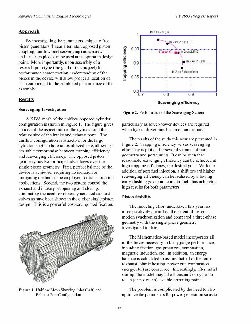
Advanced Combustion Engine Technologies FY 2005 Progress Report
Approach
By investigating the parameters unique to free piston generators (linear alternator, opposed piston coupling, uniflow port scavenging) as separate entities, each piece can be used at its optimum design point. More importantly, upon assembly of a research prototype (the goal of this project) for performance demonstration, understanding of the pieces in the device will allow proper allocation of each component to the combined performance of the assembly.
Results
Scavenging Investigation
A KIVA mesh of the uniflow opposed cylinder configuration is shown in Figure 1. The figure gives an idea of the aspect ratio of the cylinder and the relative size of the intake and exhaust ports. The uniflow configuration is attractive for the large cylinder length to bore ratios utilized here, allowing a desirable compromise between trapping efficiency and scavenging efficiency. The opposed piston geometry has two principal advantages over the single piston geometry. First, perfect balance of the device is achieved, requiring no isolation or mitigating methods to be employed for transportation applications. Second, the two pistons control the exhaust and intake port opening and closing, eliminating the need for remotely actuated exhaust valves as have been shown in the earlier single piston design. This is a powerful cost-saving modification,
Figure 1. Uniflow Mesh Showing Inlet (Left) and Exhaust Port Configuration
Figure 2. Performance of the Scavenging System
particularly as lower-power devices are required when hybrid drivetrains become more refined.
The results of the study this year are presented in Figure 2. Trapping efficiency versus scavenging efficiency is plotted for several variants of port geometry and port timing. It can be seen that reasonable scavenging efficiency can be achieved at high trapping efficiency, the desired goal. With the addition of port fuel injection, a shift toward higher scavenging efficiency can be realized by allowing early flushing gas to not contain fuel, thus achieving high results for both parameters.
Piston Stability
The modeling effort undertaken this year has more positively quantified the extent of piston motion synchronization and compared a three-phase geometry with the single-phase geometry investigated to date.
The Mathematica-based model incorporates all of the forces necessary to fairly judge performance, including friction, gas pressures, combustion, magnetic induction, etc. In addition, an energy balance is calculated to assure that all of the terms (exhaust, ohmic heating, power out, combustion energy, etc.) are conserved. Interestingly, after initial startup, the model may take thousands of cycles to reach (or not reach) a stable operating point.
The problem is complicated by the need to also optimize the parameters for power generation so as to
132
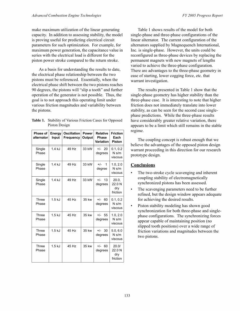
Advanced Combustion Engine Technologies FY 2005 Progress Report
make maximum utilization of the linear generating capacity. In addition to assessing stability, the model is proving useful for predicting electrical circuit parameters for such optimization. For example, for maximum power generation, the capacitance value in series with the electrical load is different for the piston power stroke compared to the return stroke.
As a basis for understanding the results to date, the electrical phase relationship between the two pistons must be referenced. Essentially, when the electrical phase shift between the two pistons reaches 90 degrees, the pistons will “slip a tooth” and further operation of the generator is not possible. Thus, the goal is to not approach this operating limit under various friction magnitudes and variability between the pistons.
Table 1. Stability of Various Friction Cases for Opposed Piston Design
Phase of alternator
Energy Input
Oscillation Frequency
Power Output
Relative Phase
Variation
Friction Each
Piston
Single 1.4 kJ 49 Hz 33 kW +/- 20 0.1, 0.2 Phase degrees N s/m
viscous
Single 1.4 kJ 49 Hz 33 kW +/- 1 1.0, 2.0 Phase degree N s/m
viscous
Single 1.4 kJ 49 Hz 33 kW +/- 13 20.0, Phase degrees 22.0 N
dry friction
Three 1.5 kJ 45 Hz 35 kw +/- 60 0.1, 0.2 Phase degrees N s/m
viscous
Three 1.5 kJ 45 Hz 35 kw +/- 55 1.0, 2.0 Phase degrees N s/m
viscous
Three 1.5 kJ 45 Hz 35 kw +/- 30 5.0, 6.0 Phase degrees N s/m
viscous
Three 1.5 kJ 45 Hz 35 kw +/- 60 20.0/ Phase degrees 22.0 N
dry friction
Table 1 shows results of the model for both single-phase and three-phase configurations of the linear alternator. The current configuration of the alternators supplied by Magnequench International, Inc. is single-phase. However, the units could be reconfigured as three-phase devices by replacing the permanent magnets with new magnets of lengths varied to achieve the three-phase configuration. There are advantages to the three-phase geometry in ease of starting, lower cogging force, etc. that warrant investigation.
The results presented in Table 1 show that the single-phase geometry has higher stability than the three-phase case. It is interesting to note that higher friction does not immediately translate into lower stability, as can be seen for the second case single-phase predictions. While the three-phase results have considerably greater relative variation, there appears to be a limit which still remains in the stable regime.
The coupling concept is robust enough that we believe the advantages of the opposed piston design warrant proceeding in this direction for our research prototype design.
Conclusions • The two-stroke cycle scavenging and inherent
coupling stability of electromagnetically synchronized pistons has been assessed.
• The scavenging parameters need to be further refined, but the design window appears adequate for achieving the desired results.
• Piston stability modeling has shown good synchronization for both three-phase and single-phase configurations. The synchronizing forces appear capable of maintaining position (no slipped tooth positions) over a wide range of friction variations and magnitudes between the two pistons.
133
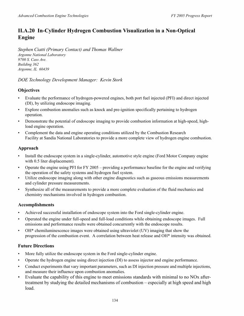
Advanced Combustion Engine Technologies FY 2005 Progress Report
II.A.20 In-Cylinder Hydrogen Combustion Visualization in a Non-Optical Engine
Stephen Ciatti (Primary Contact) and Thomas Wallner Argonne National Laboratory 9700 S. Cass Ave. Building 362 Argonne, IL 60439
DOE Technology Development Manager: Kevin Stork
Objectives • Evaluate the performance of hydrogen-powered engines, both port fuel injected (PFI) and direct injected
(DI), by utilizing endoscope imaging. • Explore combustion anomalies such as knock and pre-ignition specifically pertaining to hydrogen
operation. • Demonstrate the potential of endoscope imaging to provide combustion information at high-speed, high-
load engine operation. • Complement the data and engine operating conditions utilized by the Combustion Research
Facility at Sandia National Laboratories to provide a more complete view of hydrogen engine combustion.
Approach • Install the endoscope system in a single-cylinder, automotive style engine (Ford Motor Company engine
with 0.5 liter displacement). • Operate the engine using PFI for FY 2005 – providing a performance baseline for the engine and verifying
the operation of the safety systems and hydrogen fuel system. • Utilize endoscope imaging along with other engine diagnostics such as gaseous emissions measurements
and cylinder pressure measurements. • Synthesize all of the measurements to provide a more complete evaluation of the fluid mechanics and
chemistry mechanisms involved in hydrogen combustion.
Accomplishments • Achieved successful installation of endoscope system into the Ford single-cylinder engine. • Operated the engine under full-speed and full-load conditions while obtaining endoscope images. Full
emissions and performance results were obtained concurrently with the endoscope results. • OH* chemiluminescence images were obtained using ultraviolet (UV) imaging that show the
progression of the combustion event. A correlation between heat release and OH* intensity was obtained.
Future Directions • More fully utilize the endoscope system in the Ford single-cylinder engine. • Operate the hydrogen engine using direct injection (DI) to assess injector and engine performance. • Conduct experiments that vary important parameters, such as DI injection pressure and multiple injections,
and measure their influence upon combustion anomalies. • Evaluate the capability of this engine to meet emissions standards with minimal to no NOx after-
treatment by studying the detailed mechanisms of combustion – especially at high speed and high load.
134
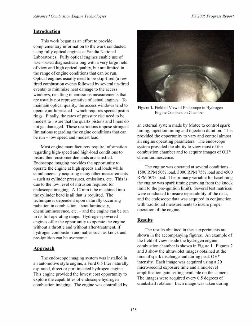
Advanced Combustion Engine Technologies FY 2005 Progress Report
Introduction
This work began as an effort to provide complementary information to the work conducted using fully optical engines at Sandia National Laboratories. Fully optical engines enable use of laser-based diagnostics along with a very large field of view and high optical quality, but are limited in the range of engine conditions that can be run. Optical engines usually need to be skip-fired (a few fired combustion events followed by several un-fired events) to minimize heat damage to the access windows, resulting in emissions measurements that are usually not representative of actual engines. To maintain optical quality, the access windows tend to operate un-lubricated – which requires special piston rings. Finally, the rates of pressure rise need to be modest to insure that the quartz pistons and liners do not get damaged. These restrictions impose stringent limitations regarding the engine conditions that can be run – low speed and modest load.
Most engine manufacturers require information regarding high-speed and high-load conditions to insure their customer demands are satisfied. Endoscope imaging provides the opportunity to operate the engine at high speeds and loads while simultaneously acquiring many other measurements – such as cylinder pressures, emissions, etc. This is due to the low level of intrusion required for endoscope imaging. A 12 mm tube machined into the cylinder head is all that is required. The technique is dependent upon naturally occurring radiation in combustion – soot luminosity, chemiluminescence, etc. – and the engine can be run in its full operating range. Hydrogen-powered engines offer the opportunity to operate the engine without a throttle and without after-treatment, if hydrogen combustion anomalies such as knock and pre-ignition can be overcome.
Approach
The endoscope imaging system was installed in an automotive style engine, a Ford 0.5 liter naturally aspirated, direct or port injected hydrogen engine. This engine provided the lowest cost opportunity to explore the capabilities of endoscope hydrogen combustion imaging. The engine was controlled by
Figure 1. Field of View of Endoscope in Hydrogen Engine Combustion Chamber
an external system made by Motec to control spark timing, injection timing and injection duration. This provided the opportunity to vary and control almost all engine operating parameters. The endoscope system provided the ability to view most of the combustion chamber and to acquire images of OH* chemiluminescence.
The engine was operated at several conditions – 1500 RPM 50% load, 3000 RPM 75% load and 4500 RPM 50% load. The primary variable for baselining the engine was spark timing (moving from the knock limit to the pre-ignition limit). Several test matrices were conducted to insure repeatability of the data, and the endoscope data was acquired in conjunction with traditional measurements to insure proper operation of the engine.
Results
The results obtained in these experiments are shown in the accompanying figures. An example of the field of view inside the hydrogen engine combustion chamber is shown in Figure 1. Figures 2 and 3 show the ultraviolet images obtained at the time of spark discharge and during peak OH* intensity. Each image was acquired using a 20 micro-second exposure time and a mid-level amplification gain setting available on the camera. The images were acquired every 0.5 degrees of crankshaft rotation. Each image was taken during
135
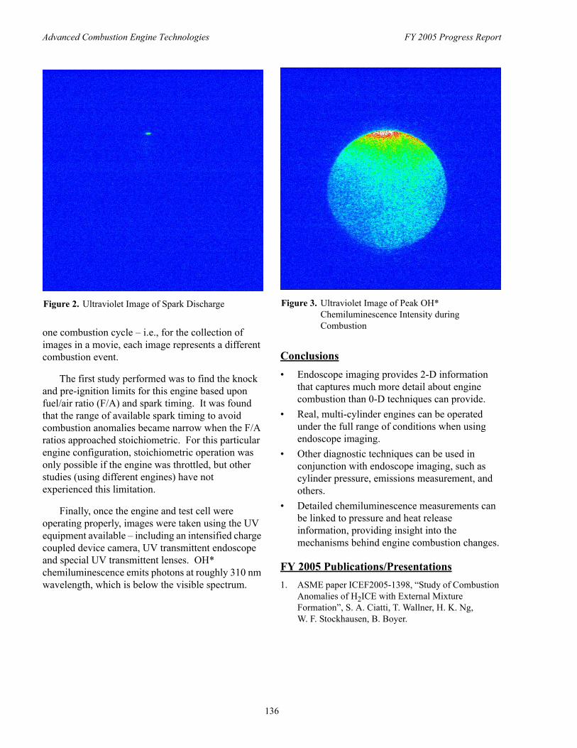
Advanced Combustion Engine Technologies FY 2005 Progress Report
Figure 2. Ultraviolet Image of Spark Discharge
one combustion cycle – i.e., for the collection of images in a movie, each image represents a different combustion event.
The first study performed was to find the knock and pre-ignition limits for this engine based upon fuel/air ratio (F/A) and spark timing. It was found that the range of available spark timing to avoid combustion anomalies became narrow when the F/A ratios approached stoichiometric. For this particular engine configuration, stoichiometric operation was only possible if the engine was throttled, but other studies (using different engines) have not experienced this limitation.
Finally, once the engine and test cell were operating properly, images were taken using the UV equipment available – including an intensified charge coupled device camera, UV transmittent endoscope and special UV transmittent lenses. OH* chemiluminescence emits photons at roughly 310 nm wavelength, which is below the visible spectrum.
Figure 3. Ultraviolet Image of Peak OH* Chemiluminescence Intensity during Combustion
Conclusions • Endoscope imaging provides 2-D information
that captures much more detail about engine combustion than 0-D techniques can provide.
• Real, multi-cylinder engines can be operated under the full range of conditions when using endoscope imaging.
• Other diagnostic techniques can be used in conjunction with endoscope imaging, such as cylinder pressure, emissions measurement, and others.
• Detailed chemiluminescence measurements can be linked to pressure and heat release information, providing insight into the mechanisms behind engine combustion changes.
FY 2005 Publications/Presentations 1. ASME paper ICEF2005-1398, “Study of Combustion
Anomalies of H2ICE with External Mixture Formation”, S. A. Ciatti, T. Wallner, H. K. Ng, W. F. Stockhausen, B. Boyer.
136
Advanced Combustion Engine Technologies FY 2005 Progress Report
II.A.21 Preliminary Evaluation of Mixture Formation and Combustion in a Hydrogen Engine using OH Chemiluminescence
Christopher WhiteSandia National Laboratories (SNL)P.O. Box 969, MS 9053 Livermore, CA 94551
DOE Technology Development Manager: Kevin Stork
Objectives • Develop the science base needed by engine companies to develop fuel-efficient, low-emissions, hydrogen-
fueled internal combustion engines (H2ICEs) and promote DOE’s long-term goal of transitioning to a hydrogen economy.
• Initial focus is to systematically investigate hydrogen-air mixing processes for engine operation with hydrogen injected directly in-cylinder.
• Provide complementary and validation data for the numerical experiments modeling Sandia’s H2ICE being conducted at the Combustion Research Facility (CRF) at SNL.
Approach • Built a world class optical engine laboratory to investigate fundamental in-cylinder engine phenomena. • Use the relatively simple imaging technique of OH chemiluminescence as a first step in a systematic
approach to study in-cylinder hydrogen-air mixing processes. • Perform experiments with well-defined initial and boundary conditions that can be used for model and grid
validation of the large eddy simulation (LES) numerical simulations.
Accomplishments • Restored and upgraded an existing optical engine laboratory to operate with hydrogen as a fuel. Notable
capabilities include: – automotive-sized single-cylinder engine with extensive optical access, – port-fuel-injection (PFI) or direct-injection (DI) hydrogen fueling, – advanced laser-based diagnostics.
• Operated the engine with hydrogen for the first time and performed systematic experiments to determine operating conditions that are suitable for an optical engine and relevant to industry.
• Preliminary OH chemiluminescence experiments have begun to assess the effects of injection variables on engine operation and mixture formation.
Future Directions • Continue the OH chemiluminescence studies to measure flame propagation characteristics and cycle-to
cycle variability and to assess mixture formation in an H2ICE for premixed and direct-injection hydrogen fueling.
• Begin experimental setup to implement the planar laser induced fluorescence (PLIF) technique that will be used to provide a spatially resolved quantitative measure of in-cylinder equivalence ratio.
• Begin to develop experimental-numerical experiments that provide fundamental physical insights that can not be determined from experiments or simulations alone.
137
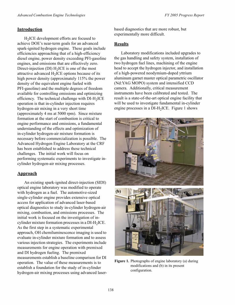
Advanced Combustion Engine Technologies FY 2005 Progress Report
Introduction
H2ICE development efforts are focused to achieve DOE’s near-term goals for an advanced spark-ignited hydrogen engine. These goals include efficiencies approaching that of a high-efficiency diesel engine, power density exceeding PFI-gasoline engines, and emissions that are effectively zero. Direct-injection (DI) H2ICE is one of the most attractive advanced H2ICE options because of its high power density (approximately 115% the power density of the equivalent engine fueled with PFI-gasoline) and the multiple degrees of freedom available for controlling emissions and optimizing efficiency. The technical challenge with DI-H2ICE operation is that in-cylinder injection requires hydrogen-air mixing in a very short time (approximately 4 ms at 5000 rpm). Since mixture formation at the start of combustion is critical to engine performance and emissions, a fundamental understanding of the effects and optimization of in-cylinder hydrogen-air mixture formation is necessary before commercialization is possible. The Advanced Hydrogen Engine Laboratory at the CRF has been established to address these technical challenges. The initial work will focus on performing systematic experiments to investigate in-cylinder hydrogen-air mixing processes.
Approach
An existing spark-ignited direct-injection (SIDI) optical engine laboratory was modified to operate with hydrogen as a fuel. The automotive-sized single-cylinder engine provides extensive optical access for application of advanced laser-based optical diagnostics to study in-cylinder hydrogen-air mixing, combustion, and emissions processes. The initial work is focused on the investigation of in-cylinder mixture formation processes in a DI-H2ICE. As the first step in a systematic experimental approach, OH chemiluminescence imaging is used to evaluate in-cylinder mixture formation and to assess various injection strategies. The experiments include measurements for engine operation with premixed and DI hydrogen fueling. The premixed measurements establish a baseline comparison for DI operation. The value of these measurements is to establish a foundation for the study of in-cylinder hydrogen-air mixing processes using advanced laser
based diagnostics that are more robust, but experimentally more difficult.
Results
Laboratory modifications included upgrades to the gas handling and safety system, installation of two hydrogen fuel lines, machining of the engine head to accept the hydrogen injector, and installation of a high-powered neodymium-doped yttrium aluminum garnet master optical parametric oscillator (Nd:YAG MOPO) system and intensified CCD camera. Additionally, critical measurement instruments have been calibrated and tested. The result is a state-of-the-art optical engine facility that will be used to investigate fundamental in-cylinder engine processes in a DI-H2ICE. Figure 1 shows
Figure 1. Photographs of engine laboratory (a) during modifications and (b) in its present configuration.
138
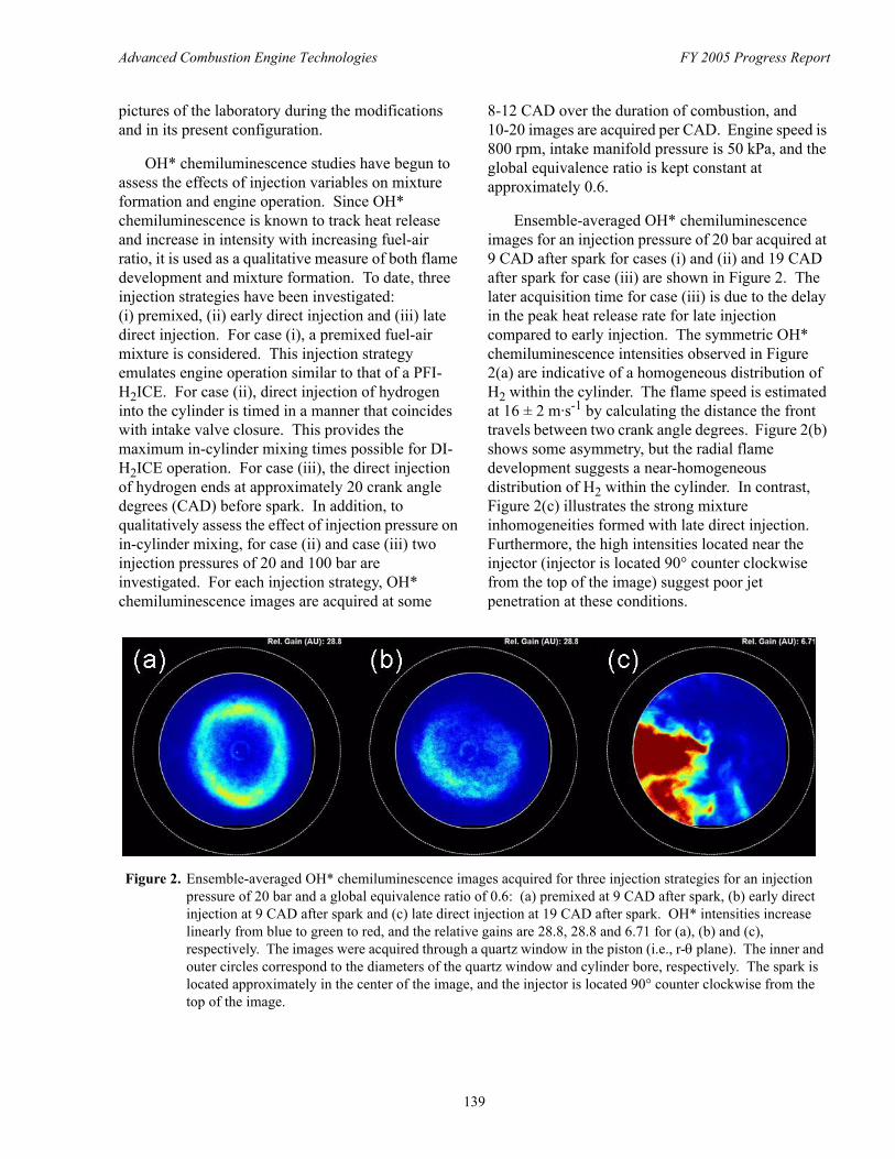
Advanced Combustion Engine Technologies FY 2005 Progress Report
pictures of the laboratory during the modifications and in its present configuration.
OH* chemiluminescence studies have begun to assess the effects of injection variables on mixture formation and engine operation. Since OH* chemiluminescence is known to track heat release and increase in intensity with increasing fuel-air ratio, it is used as a qualitative measure of both flame development and mixture formation. To date, three injection strategies have been investigated: (i) premixed, (ii) early direct injection and (iii) late direct injection. For case (i), a premixed fuel-air mixture is considered. This injection strategy emulates engine operation similar to that of a PFIH2ICE. For case (ii), direct injection of hydrogen into the cylinder is timed in a manner that coincides with intake valve closure. This provides the maximum in-cylinder mixing times possible for DIH2ICE operation. For case (iii), the direct injection of hydrogen ends at approximately 20 crank angle degrees (CAD) before spark. In addition, to qualitatively assess the effect of injection pressure on in-cylinder mixing, for case (ii) and case (iii) two injection pressures of 20 and 100 bar are investigated. For each injection strategy, OH* chemiluminescence images are acquired at some
8-12 CAD over the duration of combustion, and 10-20 images are acquired per CAD. Engine speed is 800 rpm, intake manifold pressure is 50 kPa, and the global equivalence ratio is kept constant at approximately 0.6.
Ensemble-averaged OH* chemiluminescence images for an injection pressure of 20 bar acquired at 9 CAD after spark for cases (i) and (ii) and 19 CAD after spark for case (iii) are shown in Figure 2. The later acquisition time for case (iii) is due to the delay in the peak heat release rate for late injection compared to early injection. The symmetric OH* chemiluminescence intensities observed in Figure 2(a) are indicative of a homogeneous distribution of H2 within the cylinder. The flame speed is estimated at 16 ± 2 m·s-1 by calculating the distance the front travels between two crank angle degrees. Figure 2(b) shows some asymmetry, but the radial flame development suggests a near-homogeneous distribution of H2 within the cylinder. In contrast, Figure 2(c) illustrates the strong mixture inhomogeneities formed with late direct injection. Furthermore, the high intensities located near the injector (injector is located 90° counter clockwise from the top of the image) suggest poor jet penetration at these conditions.
Figure 2. Ensemble-averaged OH* chemiluminescence images acquired for three injection strategies for an injection pressure of 20 bar and a global equivalence ratio of 0.6: (a) premixed at 9 CAD after spark, (b) early direct injection at 9 CAD after spark and (c) late direct injection at 19 CAD after spark. OH* intensities increase linearly from blue to green to red, and the relative gains are 28.8, 28.8 and 6.71 for (a), (b) and (c), respectively. The images were acquired through a quartz window in the piston (i.e., r-θ plane). The inner and outer circles correspond to the diameters of the quartz window and cylinder bore, respectively. The spark is located approximately in the center of the image, and the injector is located 90° counter clockwise from the top of the image.
139
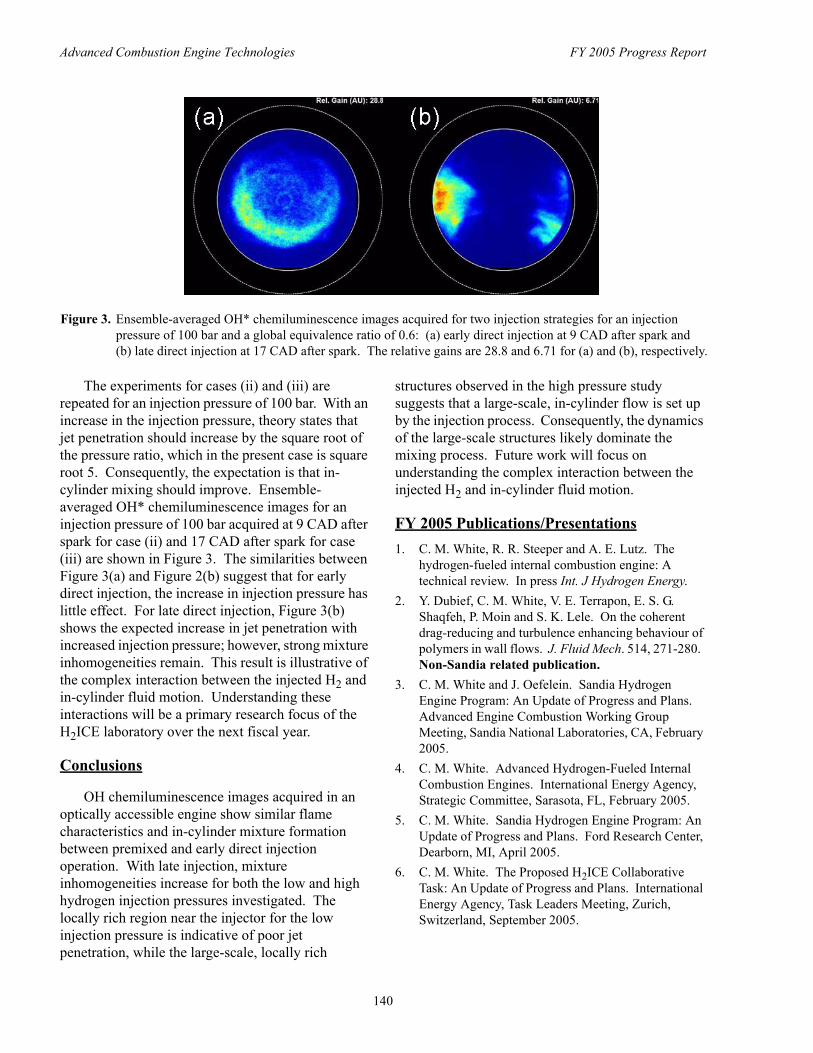
Advanced Combustion Engine Technologies FY 2005 Progress Report
Figure 3. Ensemble-averaged OH* chemiluminescence images acquired for two injection strategies for an injection pressure of 100 bar and a global equivalence ratio of 0.6: (a) early direct injection at 9 CAD after spark and (b) late direct injection at 17 CAD after spark. The relative gains are 28.8 and 6.71 for (a) and (b), respectively.
The experiments for cases (ii) and (iii) are repeated for an injection pressure of 100 bar. With an increase in the injection pressure, theory states that jet penetration should increase by the square root of the pressure ratio, which in the present case is square root 5. Consequently, the expectation is that in-cylinder mixing should improve. Ensemble-averaged OH* chemiluminescence images for an injection pressure of 100 bar acquired at 9 CAD after spark for case (ii) and 17 CAD after spark for case (iii) are shown in Figure 3. The similarities between Figure 3(a) and Figure 2(b) suggest that for early direct injection, the increase in injection pressure has little effect. For late direct injection, Figure 3(b) shows the expected increase in jet penetration with increased injection pressure; however, strong mixture inhomogeneities remain. This result is illustrative of the complex interaction between the injected H2 and in-cylinder fluid motion. Understanding these interactions will be a primary research focus of the H2ICE laboratory over the next fiscal year.
Conclusions
OH chemiluminescence images acquired in an optically accessible engine show similar flame characteristics and in-cylinder mixture formation between premixed and early direct injection operation. With late injection, mixture inhomogeneities increase for both the low and high hydrogen injection pressures investigated. The locally rich region near the injector for the low injection pressure is indicative of poor jet penetration, while the large-scale, locally rich
structures observed in the high pressure study suggests that a large-scale, in-cylinder flow is set up by the injection process. Consequently, the dynamics of the large-scale structures likely dominate the mixing process. Future work will focus on understanding the complex interaction between the injected H2 and in-cylinder fluid motion.
FY 2005 Publications/Presentations 1. C. M. White, R. R. Steeper and A. E. Lutz. The
hydrogen-fueled internal combustion engine: A technical review. In press Int. J Hydrogen Energy.
2. Y. Dubief, C. M. White, V. E. Terrapon, E. S. G. Shaqfeh, P. Moin and S. K. Lele. On the coherent drag-reducing and turbulence enhancing behaviour of polymers in wall flows. J. Fluid Mech. 514, 271-280. Non-Sandia related publication.
3. C. M. White and J. Oefelein. Sandia Hydrogen Engine Program: An Update of Progress and Plans. Advanced Engine Combustion Working Group Meeting, Sandia National Laboratories, CA, February 2005.
4. C. M. White. Advanced Hydrogen-Fueled Internal Combustion Engines. International Energy Agency, Strategic Committee, Sarasota, FL, February 2005.
5. C. M. White. Sandia Hydrogen Engine Program: An Update of Progress and Plans. Ford Research Center, Dearborn, MI, April 2005.
6. C. M. White. The Proposed H2ICE Collaborative Task: An Update of Progress and Plans. International Energy Agency, Task Leaders Meeting, Zurich, Switzerland, September 2005.
140

![HCCI - Update of Progress 2005 - US Department of Energy · HCCI – Update of Progress 2005 HCCI HCCI ... M EP [b a r] B S F C [g/k W-hr] ... Typically used in 2-Stroke Engines at](https://img.pdfslide.us/doc/110x75/5ac4ebc77f8b9a220b8d1053/hcci-update-of-progress-2005-us-department-of-energy-update-of-progress.jpg)