Embed Size (px)
Citation preview
//
I ' "_ (
ADVANCED SOLAR-PROPELLEDCARGO SPACECRAFT FOR MARS MISSIONS .2 _7,_
FINAL REPORT
Spacecraft Systems Design, AA420/499DNASA/USRA University Advanced Design Program
Iii111111111111111I11111111111111111IIII!i111111111111
I!!1111111111111111IIIIIIIIIIIIIIIIIIIII11111111111111111I1111111111111111II
Ii1111111111111111IIIIIIII!111111111IIIIIIIIIIIIIIIIllIIIIIIIIIIIIIIIIIIIIIIIIii!11111111IIIIIIIIIIIIIIII!1111111111111111111IIIIIIIIIIIIIIIIII!111111111111111IIIIIIIIIIIIIIIII
Department of Aeronautics and Astronautics
University of WashingtonSeattle, WA 98195
June 9,1989
(NASA-C.R-I d621 _ ) A_VANC El3 c;i.]L AP- _ RgP_LL _ _
C_RO_J _PAEECRAFT FOR _ARS MI3$I_N_ Fin_1
_<eport (wasl]inr_t, on Univ.1 2')7 _) CSCL 22_
N90-25164
Uncl as
0 _ 5 3 _ 9 5
https://ntrs.nasa.gov/search.jsp?R=19900015848 2018-10-05T19:58:11+00:00Z
ADVANCED SOLAR-PROPELLED
CARGO SPACECRAFT FOR MARS MISSIONS
FINAL REPORT
Spacecraft Systems Design, AA 420/499D
NASA/USRA University Advanced Design Program
Prepared By;
Jacqueline Auzias de Turenne
Mark Beall
Joseph Burianek
Anna Cinniger
Barbrina Dunmire
Eric Haberman
James Iwamoto
Stephen Johnson
Shawn McCracken
Melanie Miller
Neil Phelps
Amy Prochko
Michael Rhodes
Terri Schmitt
Jeffrey Slostad
Ronald Teeter
Johnny Thorpe
Thai Tmn
Tad Unger
Jay Womath
Faculty Advisors:
Adam P. Bruckner
Abraham Hertzberg
Department of Aeronautics and AstronauticsUniversity of Washington
Seattle, Washington 98195
June 9, 1989
ABSTRACT
At the University of Washington, three concepts for an unmanned, solar powered,
cargo spacecraft for Mars support missions have been investigated. These spacecraft are
designed to carry a 50,000 kg payload from a low Earth orbit to a low Mars orbit. Each
design uses a distinctly different propulsion system: a solar radiation absorption (SRA)
system, a solar-pumped laser (SPL) system, and a solar powered magnetoplasma-
dynamic (MPD) arc system.
The SRA directly converts solar energy to thermal energy in the propellant through
a novel process developed at the University of Washington. A solar concentrator focuses
sunlight into an absorption chamber. A mixture of hydrogen and potassium vapor absorbs
the incident radiation and is heated to approximately 3,700 K. The hot propellant gas
exhausts through a nozzle to produce thrust. The SRA has a specific impulse of
approximately 1,000 s and produces a thrust of 2,940 N using two thrust chambers.
In the SPL system, a pair of solar-pumped, multi-megawatt, CO 2 lasers in sun-
synchronous Earth orbit converts solar energy to laser energy. The laser beams are
transmitted to the spacecraft via laser relay satellites. The laser energy heats the hydrogen
propellant through a plasma breakdown process in the center of an absorption chamber.
Propellant flowing through the chamber, heated by the plasma core, expands through a
nozzle to produce thrust. The SPL has a specific impulse of 1,260 s and produces a thrust
of 1,200 N using two thrust chambers.
The MPD system uses indium phosphide solar cells to convert sunlight to
electricity, which powers the propulsion system. In this system, the argon propellant is
ionized and electromagnetically accelerated by a magnetoplasmadynamic arc to produce
thrust. The MPD spacecraft has a specific impulse of 2,490 s and produces a thrust of
100 N.
Various orbital transferoptionsare examinedfor theseconcepts. In the SRA
system,the mothership transfersthepayload into a very high Earth orbit anda small
auxiliarypropulsionsystembooststhepayloadintoaHohmanntransferto Mars. TheSPL
spacecraftreleasesthepayloadasthespacecraftpassesby Mars. Both theSRA powered
spacecraftandtheSPLpoweredspacecraftreturnto Earthfor subsequentmissions. The
MPD propelled spacecraft,however, remainsat Mars asan orbiting spacestation. A
patchedconic approximationwasusedto determineaheliocentricinterplanetarytransfer
orbit for the MPD propelled spacecraft. All three solar-poweredspacecraftuse an
aerobrakeprocedureto placethepayloadinto a low Mars parking orbit. The payload
deliverytimesrangefrom 160daysto 873days(2.39years).
PREFACE
The Department of Aeronautics and Astronautics at the University of Washington
has been a participant in the NASA/USRA University Advanced Design Program since its
inception in 1985. From the beginning, student involvement in this space design activity
has been integrated as much as possible with the faculty's NASA-funded research
program. This synergism has been highly beneficial both to the design course and to the
research. The choice of design topic, for example, has on several occasions been
motivated by the results of our research projects and, conversely, the basic research
program carried out by the faculty has benefited from the recognition of the practical
problems of design as they reflect back through the program.
Our course structure is aimed at exposing the students to a design situation which is
"real world" as much as possible within the University framework. In addition, the course
undertakes the responsibility of teaching the students those aspects of space engineering
and science which would be needed for a general capability in the field of space systems.
Students are taught the fundamentals of reentry physics, nuclear and solar power systems,
space structures and thermal management, as well as selected topics on advanced
propulsion systems and orbital mechanics. The design problems expose the students to
situations in which they must understand the complete systems dependence of structural
components, thermal components, and environmental constraints particular to space.
The current course offering consists of two 10-week academic quarters (Winter and
Spring). The first course (AA420, Space Systems Design - typical enrollment 35-45
students) is initially structured as a formal lecture/discussion series which meets 5
hrs/week. Formal lectures by the instructors and presentations by guest lecturers from
industry and NASA provide the students with the fundamental background they need to
carry out their design studies. By the second week of the quarter, the students are divided
°°°
111
into design teams whose responsibility is to address specific subsystems of the overall
design. As the design progresses, more and more time is devoted to in-class discussions
of the students' work. A teaching assistant supported by NASA/USRA funds works with
the students and helps the instructors with project management. The results of the design
study are presented at the end of the quarter in the form of formal written reports, one by
each of the design groups.
The Spring Quarter offering (AA499D - Independent Studies in Space Systems
Design) is intended to refine and advance the design developed during the Winter Quarter
and to address key unresolved problem areas. Participation in this class is elective;
typically, about half of the AA420 students sign up for this offering. Those who do are
usually the most capable and motivated students in the department. The class meets
formally three hours a week in group discussion format. Early in the quarter the students
are encouraged to submit papers on their projects to the AIAA Region VI Student
Conference. In all cases to date, the reactions of the judges to the quality of our students'
papers has been very favorable. Since the inception of the NASA/USRA program our
students have garnered several awards in the undergraduate division of the competition. At
the end of the Spring Quarter the students submit a single f'mal report on the overall design
and make an oral presentation at the annual NASA/USRA Avanced Design Summer
Conference.
Under the NASA/USRA program our students have examined various problems
relating to the critical needs of space prime power and propulsion. The choice of these
topic areas reflects the historical emphasis on space power and propulsion in the research
carried out by the faculty involved in the program. For example, in 1985 the problem of
providing space prime power for the post-space station era was explored, and a unique
solar dynamic power module capable of powering either roving or orbital space factories
was designed. A central feature of the module was the use of the liquid droplet radiator for
heat rejection, a concept developed earlier at the University of Washington under separate
iv
NASA funding. In 1986 the design of a multimegawatt nuclear space power system for
lunar base applications was undertaken. A novel variation of the liquid droplet heat
rejection system for use in a gravitational field was developed for this power system and
the results published at the 1987 Symposium on Space Nuclear Power Systems,
Albuqerque, NM. In 1987 and 1988 an engineering design study of a mass launcher
system based on the ram accelerator concept developed at the University of Washington
was carried out. This work, coupled with the results of parallel NASA-funded
investigations of this concept, was presented at the 1987 IAF Congress, Brighton,
England, and at the AIAA/ASME/SAE/ASEE 24th Joint Propulsion Conference, Boston,
MA, in 1988.
The design topic chosen for the current academic year is solar propulsion of a
cargo-carrying spacecraft to Mars. This space freighter is intended to be launched in
support of a manned mission to that planet. Three different approaches have been
investigated: solar-electric propulsion, solar-pumped laser propulsion, and solar thermal
propulsion based on the high temperature flowing gas radiation receiver concept developed
at the University of Washington under a separate NASA grant. Our students have
responded to the design challenges with enthusiasm and creativity, encouraging us to plan
follow-up studies of some of the concepts presented here.
A.P. BrucknerResearch Professor
A. HertzbergProfessor
June 9, 1989
ACKNOWLEDGEMENTS
The members of the design teams for the three solar powered spacecraft presented
in this report would like to take this opportunity to express their deep appreciation to
Professor Adam Bruckner and Professor Abraham Hertzberg of the Department of
Aeronautics and Astronautics for their countless hours of counsel and advice concerning all
aspects of a solar powered spacecraft and its travel to Mars.
We would also like to extend our gratitude to Professor Tom Mattick, also from our
Department of Aeronautics and Astronautics, for his invaluable assistance in the
development of the flowing gas radiation heater, the design of the solar-pumped laser, as
well as the transmission of the laser beam; Keith McFall, graduate student in the
Department of Aeronautics and Astronautics at the University of Washington, for his
assistance in the development and implementation of a computer p gram for a one-
dimensional temperature profile within the flowing gas radiation heater.
Thanks are also due to Professor Robert Brooks of the Department of Nuclear
Engineering for his assistance in the research and development of the laser-powered
thruster; Walter Christiansen of the Department of Aeronautics and Astronautics for his
contributions to the design of the solar-pumped laser system; Bob Soals of the Technical
Sales Support, CVI Corporation, for his assistance in optical surface materials research;
Ted Kopf and Curtis Clevan of the Jet Propulsion Laboratory for their advice and expertise
concerning various laser aiming and tracking schemes; and John Hedgepeth of Astro
Research for his assistance in structural materials and coatings for space structures.
We would also like to extend our gratitude to Dr. Tom Piverato of the Jet
Propulsion Laboratory and Dr. Karl Faymon of the NASA Lewis Research Center for their
assistance in the design of the MPD propulsion system; Irving Weinberg, also of the
NASA Lewis Research Center, Paul Stella of the Jet Propulsion Laboratory, and Professor
William Potter of the Electrical Engineering Department at the University of Washington for
vi
their aid in the developmentof the solar arrays,power conditioning systems,and the
circuity behindtheposersupplycomponents;ProfessorsKeithHolsappleandK. Y. Lin of
outDepartmentof AeronauticsandAstronautics,andMartinMikulasof theNASA Langley
ResearchCenterfor their assistancein thedevelopmentof asupportstructurefor thesolar
arraysand the mainframeof the spacecraft;StephenParisof BoeingAerospacefor his
donation of a Runge-Kuttaintegration program for orbital analysis; and lastly, R. J.
Cassadyof RocketResearchCo. for his insightful informationon the applicability of an
MPD propulsionsystem.
Our studyof aerobrakingprocedurescould not havebeencompletedwithout the
generousassistanceof ProfessorScottEberhardt,of our Departmentof Aeronautics and
Astronautics; Michael Tauber, Carol Davies, Gene Mennes, and Chul Park of the NASA
Ames Research Center; and Bob Maraia of the Johnson Spaceflight Center.
An additional note of thanks goes to the design team members Jacqueline Auzias de
Turenne, Mark Beall, Barbrina Dunmire, Melanie Miller, and Ronald Teeter, whose
diligence and hard work played a vital role in the success of this report; Anna Cinniger, our
chief editor, for her demands and deadlines which contributed to the completion of this
report; and the members of our winter quarter Space Design class of the 1988 academic
year for their contributions during the initial development stages of all three concepts.
Finally, we would like to express our deep appreciation to NASA and USRA for
their support of the University of Washington in the Advanced Design Program since its
inception. Special thanks are due to Jack Sevier, Director, and Carol Hopf, Deputy
Director, USRA Educational Programs, John Aired, Manager of the NASA/USRA
Advanced Design Program, and Barbara Rumbaugh, Senior Project Administrator of the
Advanced Design Program. We are also deeply indebted to Karl Faymon, of the NASA
Lewis Research Center, who was our "center mentor", providing us with important
literature, data and advice, and presented a topical seminar at the University. Last but not
least we would like to thank Andrew Berschauer, graduate teaching assistant, for his help
and contributions throughout the duration of the project.
vii
TABLE OF CONTENTS
I°
II.
III.
ABSTRACT ................................................................................... i
PREFACE .................................................................................... iii
ACKNOWLEDGEMENTS ................................................................. vi
INTRODUCTION ........................................................................... 1
REFERENCES ...................................................................... 5
SOLAR RADIATION ABSORFq'ION PROPELLED SPACECRAFT ............... 6
INTRODUCTION .................................................................. 7
PROPULSION THEORY ........................................................ 12
SOLAR OI:q'ICS ................................................................... 20
DESIGN OF SPACECRAFI" .................................................... 27
ORBITAL MECHANICS ......................................................... 66
CONCLUSION .................................................................... 76
NOMENCLATURE ............................................................... 77
REFERE NCE S ..................................................................... 80
SOLAR PUMPED LASER PROPELLED SPACECRAFT ........................... 84
INTRODUCTION ................................................................. 85
PROPULSION SYSTEM ......................................................... 88
LASER AND ASSOCIATED OPTICAL SYSTEM ......................... 107
SPACECRAFT RECEIVER SYSTEM ....................................... 122
SPACECRAFT DESIGN ....................................................... 126
ORBITAL MECHANICS ....................................................... 134
CONCLUSION .................................................................. 144
NOMENCLATURE ............................................................. 146
REFERENCES ................................................................... 149
IV. MAGNETOPLASMADYNAMIC PROPELLED SPACECRAFT .................. 153
INTRODUCTION ............................................................... 154
THE MPD THRUSTER ........................................................ 155
POWER SUPPLY ............................................................... 172
SPACECRAFT CONFIGURATION AND STRUCTURE ................ 183
ORBITAL MECHANICS ....................................................... 197
CONCLUSION .................................................................. 208
NOMENCLATURE ............................................................. 210
REFERENCES ................................................................... 213
V. CONCLUSION ........................................................................... 217
VI. APPENDICES ............................................................................ 221
APPENDIX A: Aerobraking at Mars .................................................. 222
APPENDIX B: Mathematical Model of Thermal Characteristicsin Thruster Chamber ................................................ 246
APPENDIX C: Analytical Methods Used in the Design of theMPD Propelled Spacecraft Structure ............................... 252
APPENDIX D: Numerical Trajectory Calculation Programs ....................... 258
I. INTRODUCTION
IlllllllllllllllllIlllllllllllllllll
IIIIIlllllllllllll_IIIIIIIIIIIIIIIIIIIIIIIIIIIIIIIIIIIIIHIIIIIIIIIIIIII1IIIIIIIIIIIIIIIIIIIIIIIIIIIIIIIIIIIIIIIIIIIIIIIIIIIIl!IIIIIIIIIIIIIII!11
IIllllllllllllllllIIIIIIIIIIIIIIIIIIIIIIIIIIIIIIIIIIIIIIIIIIIIIIIIIIIIII
IIIIIIIIIIIIIIIIIIIIIIIIIIIIIIIIIIIIIIIIIIIIIIIIIIIIIIIIIii111111111111111
I. INTRODUCTION
Jacqueline Auzias de TurenneAmy Prochko
Stephen Johnson
With the renewed interest in planetary exploration, the United States has been
considering a manned Mars mission. Such a mission should be different from the Apollo
mission to the Moon in that it should establish the initial elements of a long-term outpost
which would be utilized and expanded by subsequent manned missions over a period of
several decades. A substantial amount of supplies and equipment will be needed. As we
have learned from the Skylab, Salyut, and Mir long duration manned Earth-orbital
missions, long term exposure to zero gravity has adverse effects on human physiology;
thus, the transfer time for a manned Mars mission should be as short as possible. To
facilitate a rapid transfer, all supplies and equipment not essential to the crew need to be
transported on a separate cargo vehicle. The substantial payload masses envisioned for
such a mission will require the utilization of advanced propulsion systems capable of
specific impulses well in excess of the levels characteristic of chemical propulsion systems.
Nuclear-thermal, nuclear-electric, and solar-electric propulsion schemes, the latter two
involving ion propulsion, have been suggested for such missions during the past three
decades [1].
Students at the University of Washington have designed three new approaches for
an Earth to Mars cargo transport utilizing solar energy for propulsion. Mission
assumptions include that the U. S. manned space station is operational and that the vehicle
components are transported to low Earth orbit (LEO) by the space shuttle and assembled by
a crew from the space station. The payload consists of supplies and equipment with a mass
of 50,000 kg, which is within the range of the payload masses that have been considered
by others. The cargo ferry would be launched long before the manned mission, so that the
PRECEDING PAGE BLANK NOT FILMED
2
success of the supply mission can be ascertained before the manned mission begins its
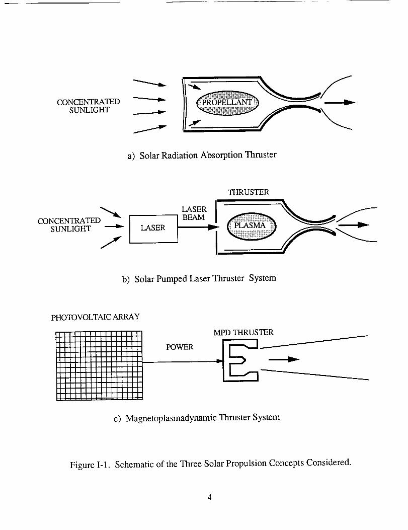
journey. The three concepts include a solar radiation absorption (SRA) propulsion system,
a solar-pumped laser (SPL) propulsion system, and a solar-powered magneto-
plasmadynamic (MPD) propulsion system. All three concepts offer specific impulses well
in excess of those achievable by chemical propulsion systems.
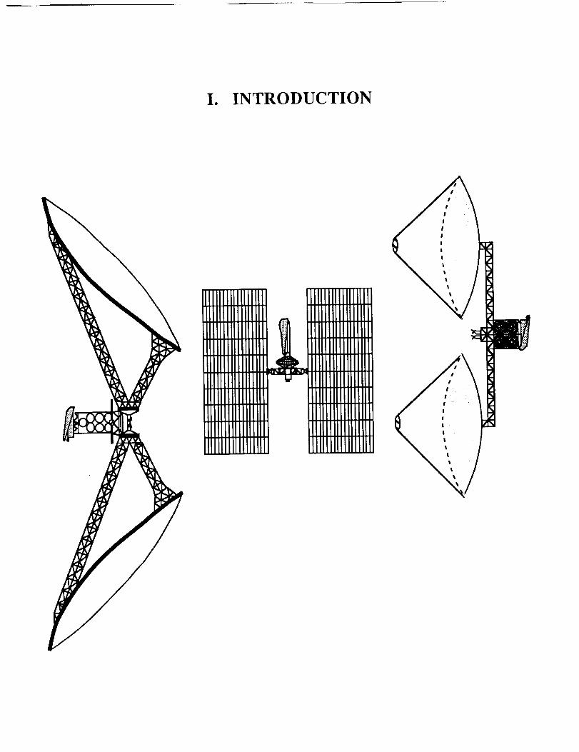
The SRA propulsion system (Fig. I-la) employs direct conversion of solar energy
to thermal energy in the propellant using a novel process developed and the University of
Washington [2]. Solar energy is concentrated using erectable reflectors and is directed
through a sapphire window into an absorption chamber. Hydrogen propellant, seeded with
an alkali metal (potassium), absorbs the incident radiation, and the heated propellant
exhausts through a nozzle to produce thrust.
In the SPL propulsion system (Fig. I-lb), the thruster aboard the cargo vessel is
powered by a remote Earth-orbiting laser system. The laser itself is powered by
concentrated solar radiation using a blackbody pumping concept capable of 15%
efficiency [3]. The laser beam is transmitted to the spacecraft, where the energy is
focussed into an absorption chamber where the hydrogen propellant is heated through a
plasma breakdown process. The heated propellant expands through a nozzle to produce
thrust.
The MPD propulsion system (Fig. I-lc) uses advanced solar cell technology
(indium phosphide) to convert sunlight to electricity, which powers the magneto-
plasmadynamic propulsion system. In this system, the argon propellant is ionized in a
diffuse electric arc and electromagnetically accelerated to produce thrust.
This report presents the three propulsion systems separately. Within each
propulsion system section is a review of the propulsion theory, a description of the
spacecraft structure, a summary of the orbital mechanics particular to each propulsion
design, and a summary of the key elements and performance characteristics.
CONCENTRATEDSUNLIGHT
a) Solar Radiation Absorption Thruster
CONCENTRATEDSUNLIGHT LASER
THRUSTER
b) Solar Pumped Laser Thruster System
PHOTOVOLTAIC ARRAY
IIIII11IllJJllII11111IIIIII1IIlilll
II111
I11iii'lit
IIIIII1IIIIIIIIIIIIII
POWER
MPD THRUSTER
c) Magnetoplasmadynamic Thruster System
Figure I-1. Schematic of the Three Solar Propulsion Concepts Considered.
4
REFERENCES
.Sutton, G., and Ross, D., Rocket Propulsion Elements, John Wiley & Sons,
New York, 1976.
. Mattick, A.T., et al., "High Temperature Solar Photon Engines", Reprinted from
the Journal Qf Energy, Vol. 3, No. 1, pp. 30-39, Jan.-Feb., 1979.
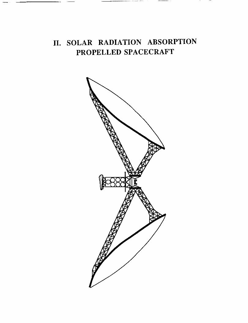
II. SOLAR RADIATION ABSORPTION
PROPELLED SPACECRAFT
INTRODUCTION
Mark BeallRonald Teeter
Thai Tran
The Solar Radiation Absorber (SRA) propulsion system was designed to use a
flowing gas volume absorber to directly convert solar energy to thermal energy in the
propellant [ 1]. The propellant is then exhausted through a nozzle to provide the thrust and
specific impulse necessary to deliver the payload to Mars. The flowing gas volume
absorber was conceived at the University of Washington by Mattick, et al. [2] in 1979.
Since then further research and experimental work by Rault [3] has led to greater
understanding of the energy transfer mechanisms and verification of the enhanced
efficiency. K. McFall is currently expanding the numerical simulation to two dimensions.
The flowing gas volume absorber has the advantage of direct energy absorption since the
energy is not transformed into an intermediate form (eg. mechanical or electrical) or
converted to another wavelength (eg. lasers, microwaves, etc.). In addition, the direct
absorption of radiant energy by the propellant avoids some of the limitations of earlier solar
thermal propulsion systems [4].
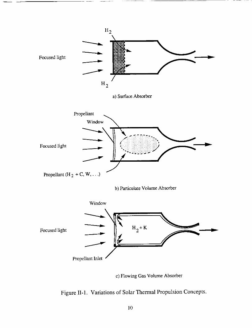
Past efforts to couple solar radiation to a working fluid have concentrated on two
concepts: surface absorbers and particulate volume absorbers. The surface absorber,
shown schematically in Fig. II-la, is the simplest method to transfer radiant solar energy to
the fluid since the energy is absorbed by a heat exchanger surface or in a black-body cavity.
In this concept broadband radiant energy is absorbed and heats a solid surface. This heat
energy is transferred by conduction and convection to the working fluid (propellant) which
is exhausted through a nozzle to produce thrust. Although this method has been used in
terrestrial power production, it is not currently suitable for space propulsion since
maximum allowable material temperatures (and therefore propellant temperatures) result in
low specific impulses. In addition, Mattick, et. al. have shown that the efficiency of the
7
surfaceabsorberdeclinesrapidlywith increasingtemperatures[2]. Evenwith futurehigh
temperaturematerialdevelopmentsthe low efficiency of surfaceabsorberswill preclude
their use for spacepropulsion. Theparticulatevolumeabsorber,seeFig. II-lb, is more
complexconceptthanthesurfaceabsorber.In thisconcept,apropellantgas(hydrogen)is
seededwith a cloud of broadbandabsorbingsolid particles. The particles absorbthe
incidentsolarenergyandtransfertheir heatenergyto thehydrogenthroughconductionand
convection. The heatedparticulateseededhydrogenpropellant is exhaustedthrough a
nozzleto producethrust. Theparticulatevolumeabsorber,like thesurfaceabsorber,is not
well suitedfor spacepropulsion.Theparticulatemassexcessivelyincreasesthemolecular
weightof thepropellantwhich decreasesthespecificimpulse. Also, evenfor very small
particlestheenergytransferfrom particlesto gasis very slow, requiring long residence
times and thus long thrust chambers. In addition, the problemsof reduced receiver
efficiency due to depositionof particleson the window and performancelossesdue to
nozzlethroaterosionhaveyet to besolved.
In the SRA thruster, shown schematically in Fig. II-lc, radiant energy is
transferred through a transparentwindow to the propellant gas contained inside a
pressurizedabsorptionchamber.This energyis absorbedvolumetrically by thegasasit
travelsfrom thefront (windowend)to theback(nozzleend)of thechamber,thusraising
theenthalpyof thepropellant.Properselectionof thepropellantgasenablesthecoolergas
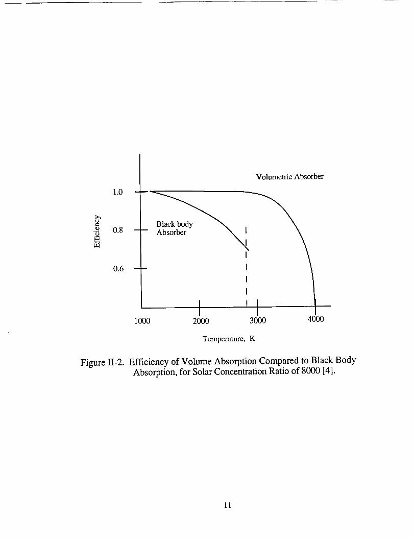
in thevicinity of thewindow to absorbthereradiatedenergyfrom thehotter gasdeeper
inside the chamber. This radiation trapping resultsin a higher receiver efficiency, as
shown in Fig. II-2, since the power loss due to reradiation is characterizedby the
temperatureof the cool gasnearthewindow, while thetemperaturefor propulsiveuseis
thepeak temperatureof the hot gasnearthenozzle. This higher temperatureresultsin
higherexit velocitiesandlarger specificimpulses. Sinceno heattransferthroughsolid
materials is required to heat the propellant, the operatingtemperatureand propulsion
performancecanbeincreased.

Thefollowing sectionsoutlinethedesignof aspacecraftusingtheSRApropulsion
concept.First, the theorybehindtheflowing gasvolumeabsorberis summarized.Next,
theoptical systemthat providesthe powerfor the propulsionsystemis discussed.The
actualdesignof eachof thecomponentsof thespacecraftis thengiven,concentratingon
thethruster,thestructurefor theopticalsystemandthepropellantstoragesystem.Finally,
theorbitalmechanicsfor theMarscargodeliverymissionarediscussed.
9
Focusedfight
H2
__ y
H2
a) Surface Absorber
y
Propellant
Window
Focused light t'....-- r
Propellant (H 2 + C, W .... )
b) Particulate Volume Absorber
Window
Focused light H 2 + K__ v
Propellant Inlet
c) Flowing Gas Volume Absorber
Figure II-1. Variations of Solar Thermal Propulsion Concepts.
10
1.0
0.8°,.._
0.6
i000
Volumetric Absorber
Absorber NN_
I
I
I
I
I '2000 3000 4000
Temperature, K
Figure 11-2. Efficiency of Volume Absorption Compared to Black Body
Absorption, for Solar Concentration Ratio of 8000 [4].
11
PROPULSION THEORY
Ronald Teeter
MATHEMATICAL MODEL
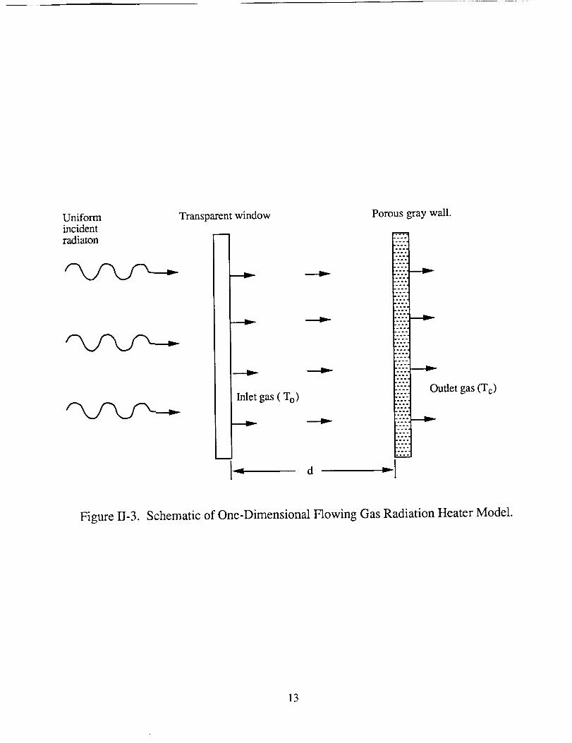
A one-dimensional model, developed by A. T. Mattick, is used to predict the
performance of the flowing gas volume absorber [1]. This model, shown in Fig. II-3 is
one dimensional, and includes only axial radiative heat transfer and convection. It also
assumes that the radiation enters through a perfectly transparent window. A porous, grey
back wall is assumed to be separated from the window by a distance d. The window
transmits concentrated solar radiation with intensity, I s , and the back wall radiates with
emissivity, E, at a temperature,T w. In addition, constant pressure, inviscid, non-heat
conducting, and constant heat capacity ideal gas flow is assumed. The absorption
characteristics of the flowing gas are specified with respect to wavelength. Mattick reduced
the necessary energy and heat transfer equations to,
J Jr'pmuCp[T(x)-To] = Jo Ijo l'tlv+(O'l't_l"e-Xdg+PF(xv'_)]dP"
+ tzv(x ')Ivu[T(x ')] [G(_v._'vb-pH(x_,v_l]dx'
+-_ Ivb(Tw)C('Cv)}2 (II-1)
where,
C('¢v) = 2[E3('l:vo-'l:v)- E3(1:vo)]
/exp[(% - 2_0)/g]- exp(- 2%0)/gF('cv,_) = texp(q:vo)/BC(Xv )
H('gv,'g'v } = JE2('gv° - 'Cv- '_'v) - E2(2%O - X'v)IE2('Cv0 "l:v '_'v) Z2(2'_v0 'l;'v)
(specular reflection)
(diffuse reflection)
( specular reflection)
(diffuse reflection)
12
Uniformincidentradiaton
Transparentwindow
i
Inlet gas ( T o)
Porous gray wall.
Imo
olo
oo.
°ol.o°
°°.
ooo
ooo
o°.
ooo
ooo
ooo
ooo
ooo
o_o
ooo
ioo
ooo
oo°
Outlet gas (T c)
Figure II-3. Schematic of One-Dimensional Flowing Gas Radiation Heater Model.
13
=- -
sgn(x) = sign of x;
E 2 and E 3 are exponential integrals while C, F, G, and H are functions of frequency v and
position x. This equation was numerically integrated to obtain a temperature profile in the
absorption chamber for a particular set of boundary conditions and propellant properties. A
FORTRAN program written by K. McFall [5] was used to perform the calculations.
PROPELLANT SELECTION
The propellant for the SRA thrusters must satisfy two requirements. First, in order
to maintain a high efficiency, the propellant must readily absorb solar radiation. Second, to
provide a high specific impulse, the propellant must have a low molecular weight. A
propellant consisting of two or more gases is necessary to meet both criteria. Alkali metal
vapors can readily absorb the concentrated solar energy, however, their high molecular
weights preclude their use as the primary propellant. Mixing the alkali metal vapor with a
light gas such as hydrogen results in a propellant that has good absorption properties, as
well as a low molecular weight.
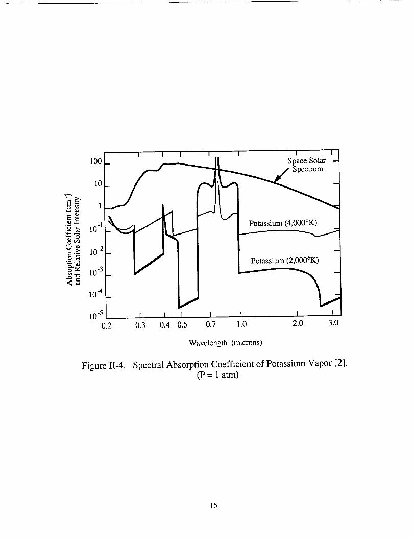
Potassium was chosen for the alkali metal vapor because it absorbs a broad band of
the solar spectrum (See Fig. II-4) and facilitates complete absorption of the incident
radiation within a short distance. Potassium vapor has its strongest absorption mechanism
in the 7,676 A doublet transition of the potassium atom. Although the absorption over a
broad part of the spectrum is weak at low temperatures, absorption improves with
increasing temperature and pressure due to the effects of photoionization, inverse
bremsstahlung, and K-photoionization [3]. Continuum absorption has also been observed
but this was not considered due to a lack of reliable experimental data. At elevated
14
i
° *..,4o
O
=.>°.dJ.._
@ on
<_
I I
10
1
.1 _10 _
10"2
10 .3
10 4
10 5 I I
0.2 0.3 0.4
I I i I
Space SolarSpectrum
Potassium (4,000°K)
Potassium (2,000°K)
I I I I
0.5 0.7 1.0 2.0 3.0
Wavelength (microns)
Figure II-4. Spectral Absorption Coefficient of Potassium Vapor [2].(P= 1 atm)
15
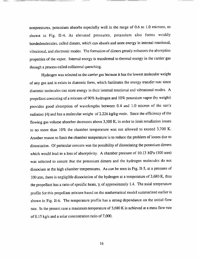
temperatures,potassiumabsorbsespeciallywell in therangeof 0.6 to 1.0 microns,as
shown in Fig. 11-4. At elevated pressures, potassium also forms weakly
bondedmolecules,calleddimers,whichcanabsorbandstoreenergyin internalrotational,
vibrational,andelectronicmodes.Theformationof dimersgreatlyenhancestheabsorption
propertiesof thevapor. Internalenergyis transferredto thermalenergyin thecarriergas
throughaprocesscalledcollisionalquenching.
Hydrogenwasselectedasthecarriergasbecauseit hasthelowestmolecularweight
of anygasandit existsin diatomicform, which facilitatesthe energytransferratesince
diatomicmoleculescanstoreenergyin theirinternalrotationalandvibrationalmodes.A
propellantconsistingof amixtureof 90%hydrogenand10%potassiumvapor(by weight)
provides good absorption of wavelengthsbetween0.4 and 1.0 micron of the sun's
radiation[4] andhasamolecularweight of 2.226kg/kg-mole. Sincetheefficiencyof the
flowing gasvolumeabsorberdecreasesabove3,500K, in orderto limit reradiationlosses
to no more than 10% the chambertemperaturewas not allowed to exceed3,700 K.
Anotherreasonto limit thechambertemperatureis to reducetheproblemof lossesdueto
dissociation.Of particularconcernwasthepossibilityof dissociatingthepotassiumdimers
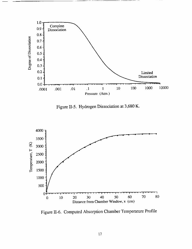
which would leadto alossof absorptivity. A chamberpressureof 10.13MPa(100 atm)
was selectedto ensurethat the potassiumdimers and the hydrogenmoleculesdo not
dissociateat thehigh chambertemperatures.As canbeseenin Fig. 1I-5,at apressureof
100atm,thereis negligibledissociationof thehydrogenat a temperatureof 3,680K, thus
thepropellanthasaratio of specificheats,T,of approximately1.4. The axial temperature
profile for thispropellantmixturebasedon themathematicalmodelsummarizedearlieris
shownin Fig. I1-6. The temperatureprofile hasa strongdependanceon the initial flow
rate. In thepresentcaseamaximumtemperatureof 3,680K isachievedatamassflow rate
of 0.15kg/sanda solarconcentrationratioof 7,000.
16
O
o,,,_
O
co
1.0
0.9
0.8
0.7
0.6
0.5
0.4
0.3
0.2
0.1
0.0
.0001
CompleteDissociation
.001 .01
Limited• o °
SOClauon
.1 1 10 100 1000 10000
Pressure (Atm.)
Figure II-5. Hydrogen Dissociation at 3,680 K.
4000
3500
3000
250O
i 2000
1500
1000
5OO
0
!
i ' ' ' ' I ' " ' ' I " ' ' ' I ' " ' ' I ' ' ' " l " ' | ' I " ' ' ' I ' ' | ' I
0 10 20 30 40 50 60 70 80
Distance from Chamber Window, x (cm)
Figure 11-6. Computed Absorption Chamber Temperature Profile
17
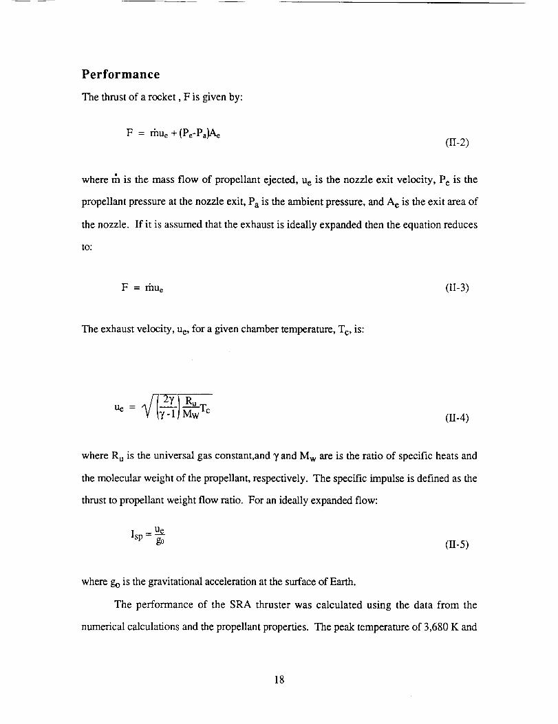
Performance
The thrust of a rocket, F is given by:
F = l'i'lUe+ (Pe-Pa)Ae(II-2)
where rh is the mass flow of propellant ejected, u e is the nozzle exit velocity, Pe is the
propellant pressure at the nozzle exit, Pa is the ambient pressure, and A e is the exit area of
the nozzle. If it is assumed that the exhaust is ideally expanded then the equation reduces
tO"
F = rhue (II-3)
The exhaust velocity, ue, for a given chamber temperature, T c, is:
2T RuUe:(H-4)
where R u is the universal gas constant,and T and M w are is the ratio of specific heats and
the molecular weight of the propellant, respectively. The specific impulse is defined as the
thrust to propellant weight flow ratio. For an ideally expanded flow:
0J-5)
where go is the gravitational acceleration at the surface of Earth.
The performance of the SRA thruster was calculated using the data from the
numerical calculations and the propellant properties. The peak temperature of 3,680 K and
18
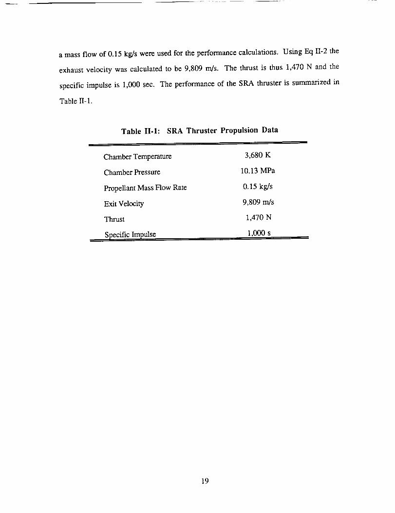
a massflow of 0.15kg/s wereusedfor theperformancecalculations. Using Eq 1I-2the
exhaustvelocity was calculatedto be 9,809 m/s. The thrust is thus 1,470 N and the
specificimpulse is 1,000sec. The performanceof the SRA thruster is summarizedin
TableII- 1.
Table II.1: SRA Thruster Propulsion Data
Chamber Temperature
Chamber Pressure
Propellant Mass Flow Rate
Exit Velocity
Thrust
SPecific Impulse
3,680 K
10.13 MPa
0.15 kg/s
9,809 rn/s
1,470 N
1,000 s
19
SOLAR OPTICS
Thai Tran
An optical system is required to concentrate and deliver solar energy into the rocket
engine chamber to heat the alkali-seeded hydrogen gas. A solar concentration ratio
sufficient to achieve a specific impulse of at least 1,000 s was specified. The system is
designed to track the sun during periods of thrust.
CONCENTRATING SOLAR RAYS
The Concave Light Amplification Mirrors (CLAM) system is used to concentrate
the 1.33 kW/m 2 solar intensity available in the vicinity of the earth to the 24 MW/m 2
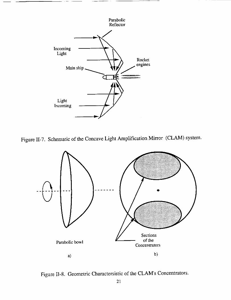
intensity needed by the thermal rockets. Figure II-7 schematically shows two concentrators
of the CLAM system focusing the solar radiation into two rocket engines. The
concentrators are off-axis sections of a paraboloid of rotation created by rotating a parabolic
curve (focal length 35 m) about its axis of symmetry, as shown in Fig. II-8a. As shown in
Fig. II-8b, the frontal view of these sections are elliptical (with a major axis of 122 m and a
minor axis of 86 m). This configuration is similar to the one discussed by Shoji [6].
The total power, PR, delivered to each thruster by a CLAM section is calculated from
PR = rlcIsAc (II-6)
where rlc is the reflective efficiency of the concentrator (taken to be 0.85 for the chosen
reflecting surface. The details of the concentrators will be discussed later), Is is the
incoming solar intensity (1.33 KW/m 2) and A c is the collector's frontal area. The total
power delivered to the image by each concentrator is 10.1 MW.
20
ParabolicReflector
IncomingLight
Main ship
Rocketengines
LightIncoming
Figure I1-7. Schematic of the Concave Light Amplification Mirror (CLAM) system.
Parabolic bowl
a)
Sections
of the
Concentrators
b)
Figure 1I-8. Geometric Charactersistic of the CLAM's Concentrators.
21
Image Analysis
As mentionedearlier,the CLAM systemis similar to the concentratorsystemchosenby
Shoji [6]. However,whereasShojiusedcircularfrontal projections(CFP),theCLAM has
elliptical frontalprojections.Givena specificfrontal area,theCLAM canprovideagreater
concentrationratio than the circular projection. An area concentrationratio, CR, is
definedas,
Collector area
CR = Image Area (II-7)
The CLAM system achieves higher CR than a CFP system by reducing the distance
between the farthest tip of the concentrator to the focal point. Reducing this distance
reduces the size of the image. The ray tracing analysis relating the image size and the
distance between the concentrators' reflecting surfaces is as follows:
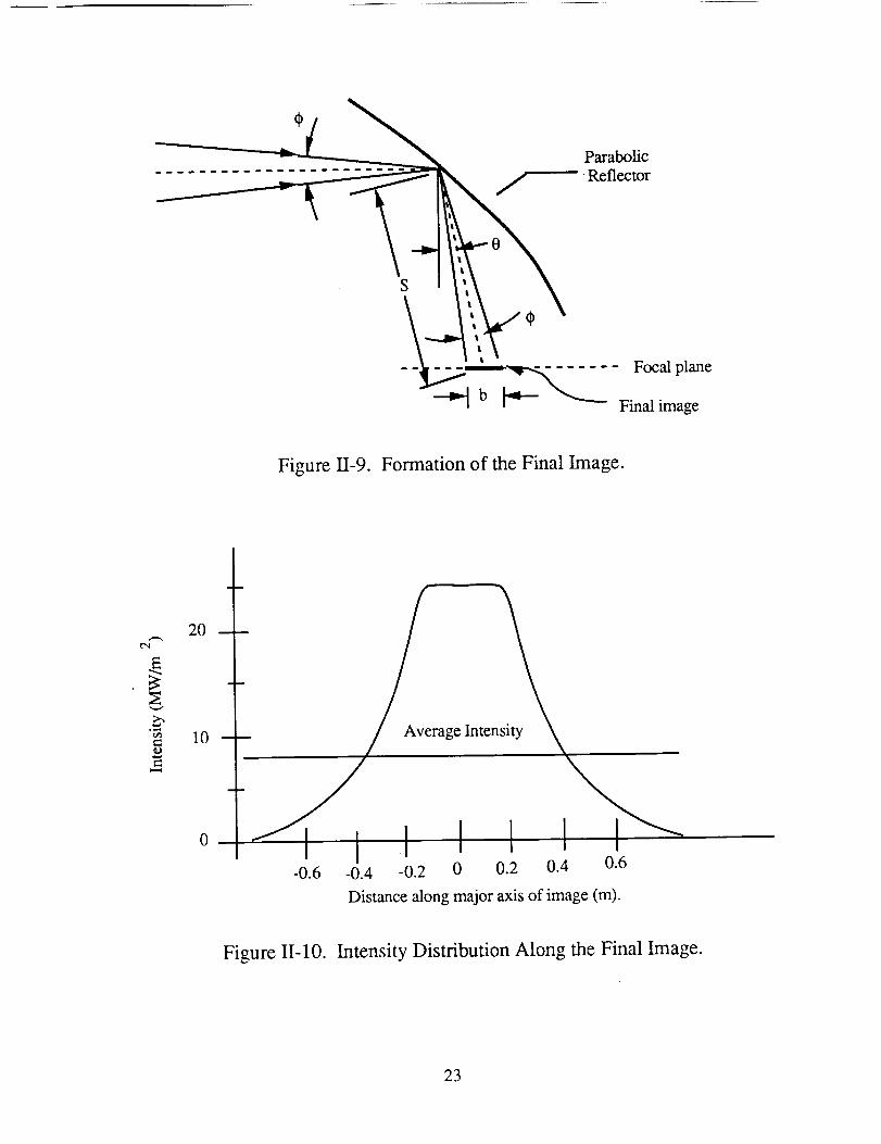
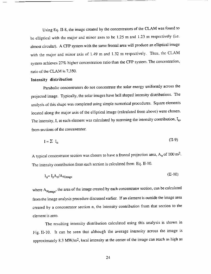
Consider a parabolic reflecting surface as shown in Fig. 1I-9. Sunlight which
strikes the surface with a subtended angle, 9, of 0.5 ° (8.7x10 -3 radians) will be reflected
toward the focal point at a spreading angle of 0.5 °. The image formed on the focal plane
by a reflection from an element of surface will be an ellipse with a major axis length bim
calculated as follows:
bim -
cos(0) (H-8)
where S is the distance from the reflecting surface to the focal point and 0 is the angle
between S and the CLAM's rotating axis. The size of the final image is found by
superimposing the images created by the reflecting surfaces from the rim of the
concentrators.
22
Parabolic_ Reflector
Focalplane
Finalimage
Figure 11-9. Formation of the Final Image.
O,I
20
10
0
rage Inten
I"/I I I I I I I ''_-0.6 -0.4 -0.2 0 0.2 0.4 0.6
Distance along major axis of image (m).
Figure 11-10. Intensity Distribution Along the Final Image.
23
UsingEq. 11-8,the imagecreatedby theconcentratorsof the CLAM was found to
be elliptical with the major and minor axes to be 1.25 m and 1.23 m respectively (i.e.
almost circular). A CFP system with the same frontal area will produce an elliptical image
with the major and minor axis of 1.49 m and 1.32 m respectively. Thus, the CLAM
system achieves 27% higher concentration ratio than the CFP system. The concentration,
ratio of the CLAM is 7,350.
Intensity distribution
Parabolic concentrators do not concentrate the solar energy uniformly across the
projected image. Typically, the solar images have bell shaped intensity distributions. The
analysis of this shape was completed using simple numerical procedures. Square elements
located along the major axis of the elliptical image (calculated from above) were chosen.
The intensity, I, at each element was calculated by summing the intensity contribution, In,
from sections of the concentrator.
I = Y; In (1I-9)
A typical concentrator section was chosen to have a frontal projection area, A n of 100 m 2.
The intensity contribution from each section is calculated from Eq. II-10.
In= IsAn/Anlmag e (II- 10)
where Anlmag e, the area of the image created by each concentrator section, can be calculated
from the image analysis procedure discussed earlier. If an element is outside the image area
created by a concentrator section n, the intensity contribution from that section to the
element is zero.
The resulting intensity distribution calculated using this analysis is shown in
Fig. II-10. It can be seen that although the average intensity across the image is
approximately 8.3 MW/m 2, local intensity at the center of the image can reach as high as
24
24MW/m2. TheSRA thrustercanachievegreaterthermalefficiencyby utilizing only the
high intensityat thecenterof the image. This is discussedfurther in the enginedesign
section.
SOLAR TRACKING
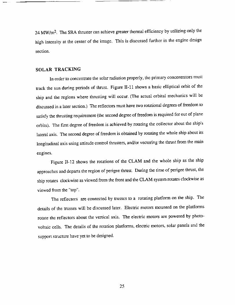
In order to concentrate the solar radiation properly, the primary concentrators must
track the sun during periods of thrust. Figure II-11 shows a basic elliptical orbit of the
ship and the regions where thrusting will occur. (The actual orbital mechanics will be
discussed in a later section.) The reflectors must have two rotational degrees of freedom to
satisfy the thrusting requirement (the second degree of freedom is required for out of plane
orbits). The first degree of freedom is achieved by rotating the collector about the ship's
lateral axis. The second degree of freedom is obtained by rotating the whole ship about its
longitudinal axis using attitude control thrusters, and/or vectoring the thrust from the main
engines.
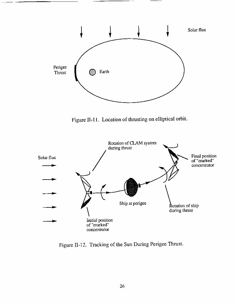
Figure II-12 shows the rotations of the CLAM and the whole ship as the ship
approaches and departs the region of perigee thrust. During the time of perigee thrust, the
ship rotates clockwise as viewed from the front and the CLAM system rotates clockwise as
viewed from the "top".
The reflectors are connected by trusses to a rotating platform on the ship. The
details of the trusses will be discussed later. Electric motors mounted on the platforms
rotate the reflectors about the vertical axis. The electric motors are powered by photo-
voltaic cells. The details of the rotation platforms, electric motors, solar panels and the
support structure have yet to be designed.
25
PerigeeThrust
Solarflux
Figure II- 11. Location of thrusting on elliptical orbit.
Solarflux
Rotationof CLAM system. duringthrust
/ _ItlL_ Final position
/ _r - of"marked"
/ concentrator
f Ship at perigee l_otafion of ship
during thrust
Initial positionof "marked"
concentrator
Figure 11-12. Tracking of the Sun During Perigee Thrust.
26
DESIGN OF SPACECRAFT
Mark BeallRonald Teeter
Thai Tran
GENERAL
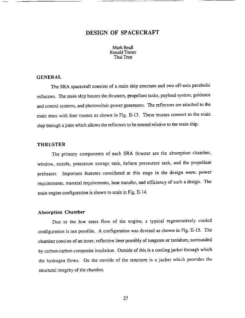
The SPA spacecraft consists of a main ship structure and two off-axis parabolic
reflectors. The main ship houses the thrusters, propellant tanks, payload system, guidance
and control systems, and photovoltaic power generators. The reflectors are attached to the
main truss with four trusses as shown in Fig. 11-13. These trusses connect to the main
ship through a joint which allows the reflectors to be rotated relative to the main ship.
THRUSTER
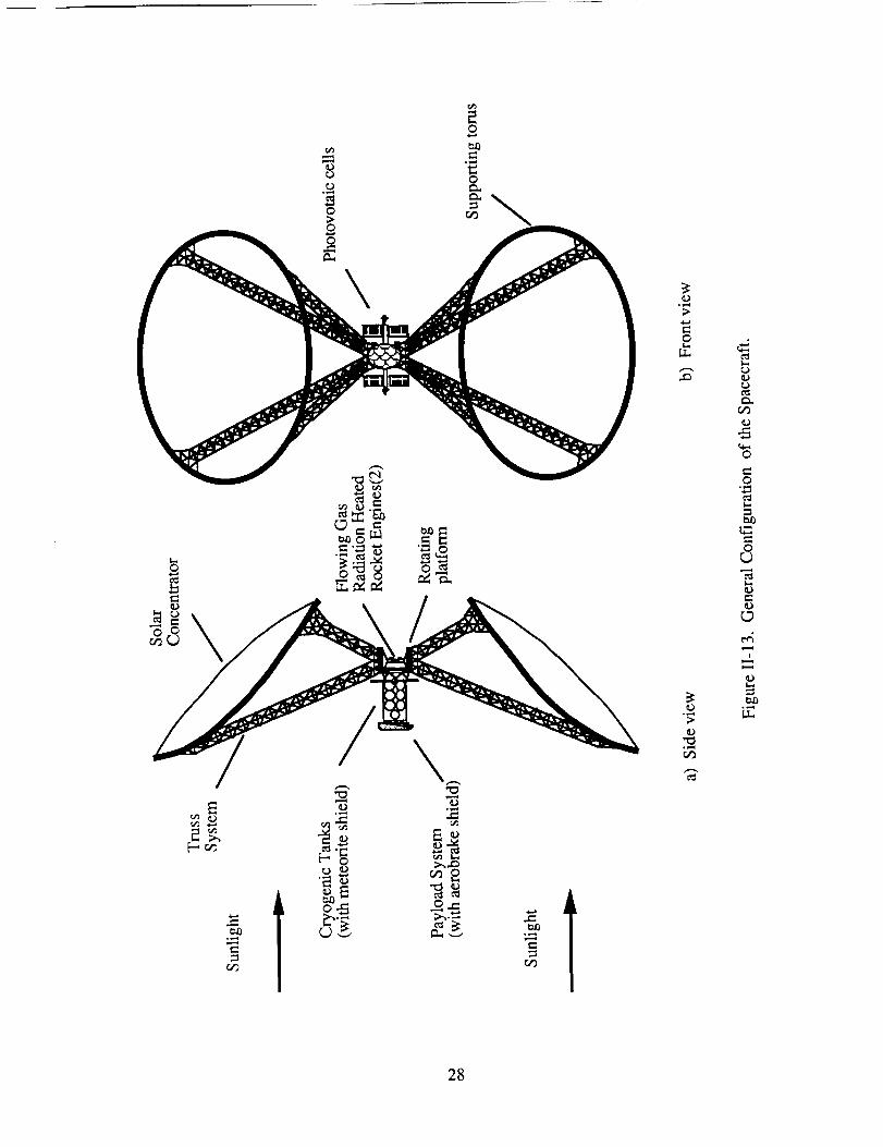
The primary components of each SRA thruster are the absorption chamber,
window, nozzle, potassium storage tank, helium pressurant tank, and the propellant
preheater. Important features considered at this stage in the design were: power
requirements, material requirements, heat transfer, and efficiency of such a design. The
main engine configuration is shown to scale in Fig. II-14.
Absorption Chamber
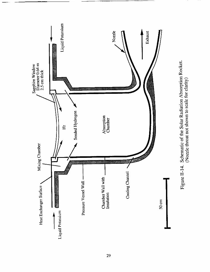
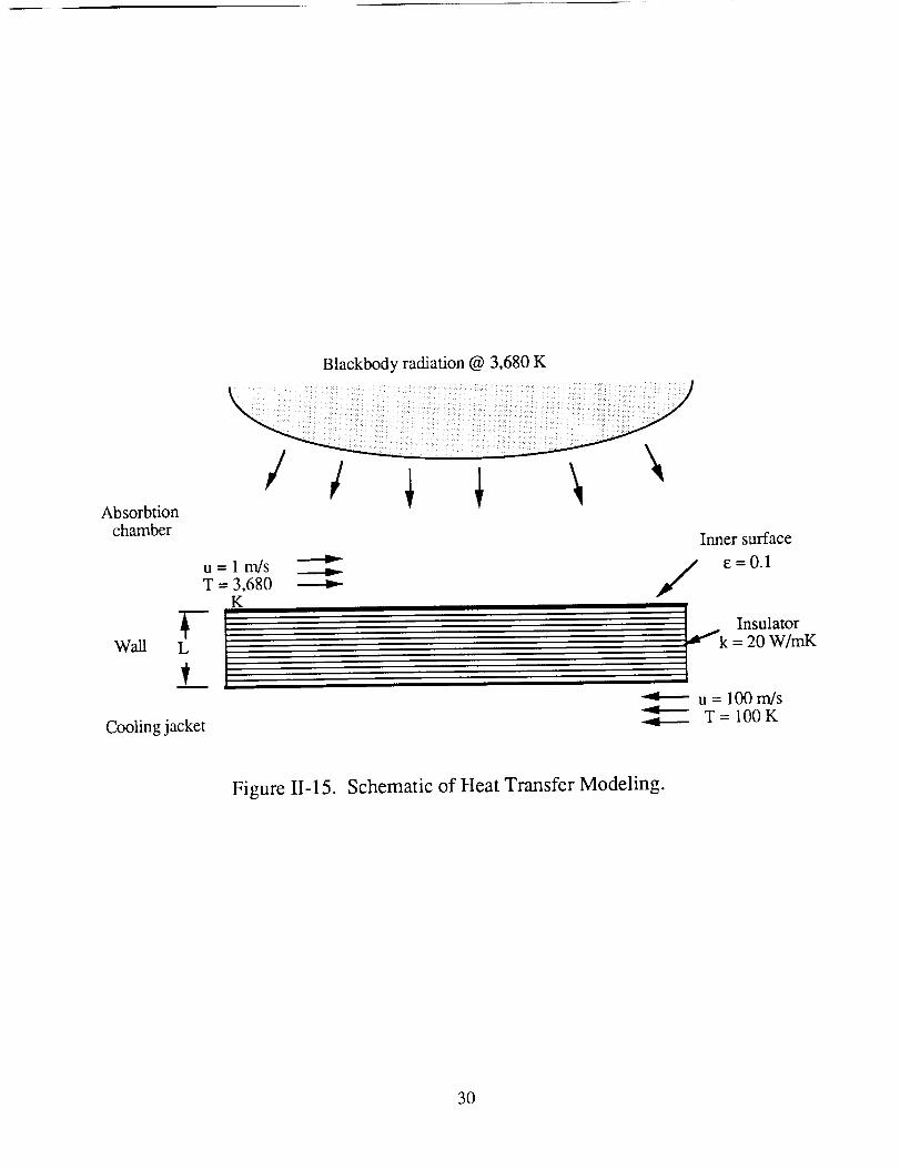
Due to the low mass flow of the engine, a typical regeneratively cooled
configuration is not possible. A configuration was devised as shown in Fig. I1-15. The
chamber consists of an inner, reflective liner possibly of tungsten or tantalum, surrounded
by carbon-carbon composite insulation. Outside of this is a cooling jacket through which
the hydrogen flows. On the outside of the structure is a jacket which provides the
structural integrity of the chamber.
27
l
c_o1,,_
0
tm_
c_
c_
c_
O
0
c_
O
c_
o_ml
28
Q_
,..=q
r_
r_
c_
f..=,l
29
q.....q
N0
Z
cJ
E
• m
0
0,--_
r_ ._
°_._
°_,._
L_
m
Blackbody radiation @ 3,680 K
Absorbtionchamber
Wall
Inner surface
/ e=O.1u = 1 rn/sT = 3,680
K
Cooling j ac ket
u = 100 m/s
T= 100K
Figure II-15. Schematic of Heat Transfer Modeling.
3O
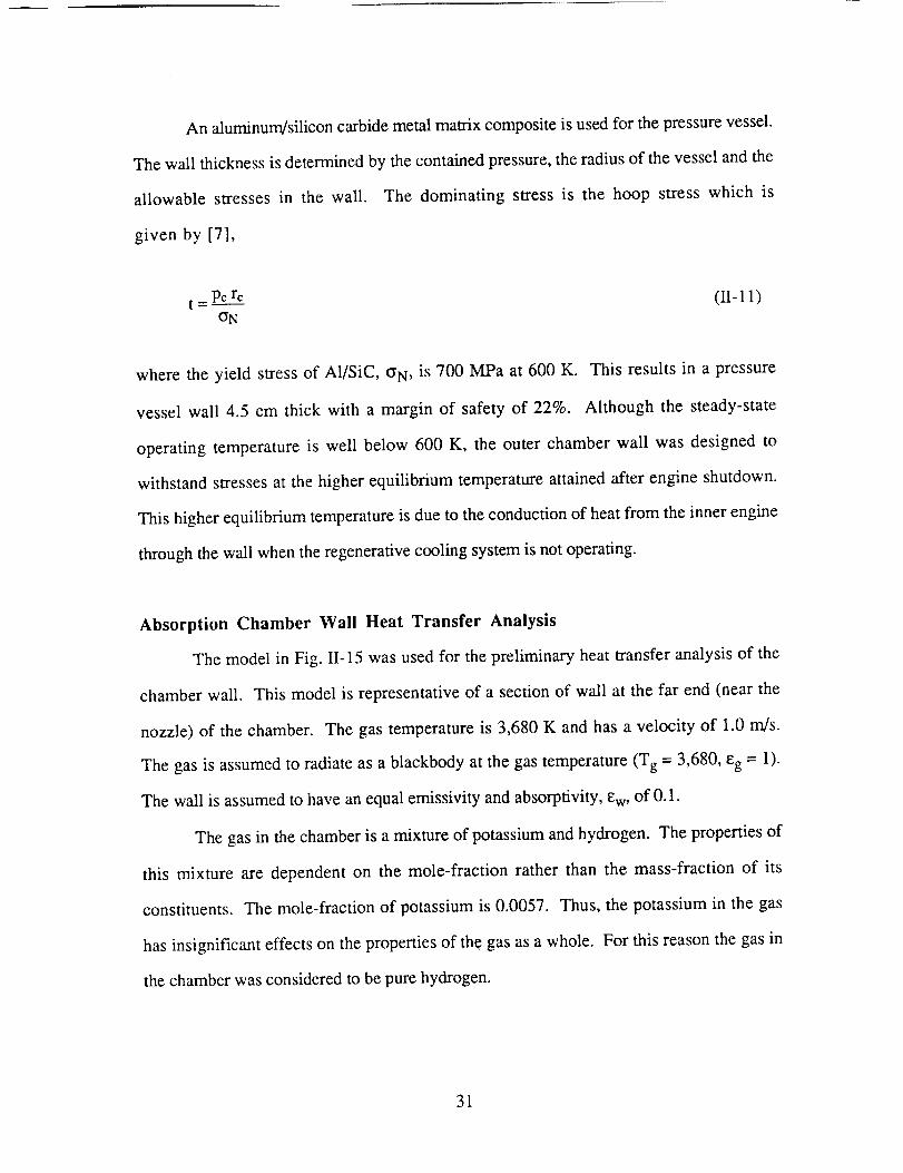
An aluminum/siliconcarbidemetalmatrixcompositeis usedfor thepressurevessel.
Thewall thicknessis determinedby thecontainedpressure,theradiusof thevesselandthe
allowable stressesin the wall. The dominating stressis the hoop stress which is
given by [7],
t = Pcre (II- 11)(IN
where the yield stress of A1/SiC, (IN, is 700 MPa at 600 K. This results in a pressure
vessel wall 4.5 cm thick with a margin of safety of 22%. Although the steady-state
operating temperature is well below 600 K, the outer chamber wall was designed to
withstand stresses at the higher equilibrium temperature attained after engine shutdown.
This higher equilibrium temperature is due to the conduction of heat from the inner engine
through the wall when the regenerative cooling system is not operating.
Absorption Chamber Wall Heat Transfer Analysis
The model in Fig. II-15 was used for the preliminary heat transfer analysis of the
chamber wall. This model is representative of a section of wall at the far end (near the
nozzle) of the chamber. The gas temperature is 3,680 K and has a velocity of 1.0 m/s.
The gas is assumed to radiate as a blackbody at the gas temperature (Tg = 3,680, eg = 1).
The wall is assumed to have an equal emissivity and absorptivity, Ew, of 0.1.
The gas in the chamber is a mixture of potassium and hydrogen. The properties of
this mixture are dependent on the mole-fraction rather than the mass-fraction of its
constituents. The mole-fraction of potassium is 0.0057. Thus, the potassium in the gas
has insignificant effects on the properties of the gas as a whole. For this reason the gas in
the chamber was considered to be pure hydrogen.
31
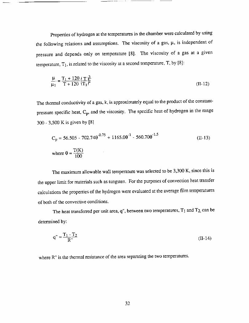
Propertiesof hydrogenatthetemperaturesin thechamberwerecalculatedby using
the following relationsand assumptions.The viscosityof a gas,it, is independentof
pressureand dependsonly on temperature[8]. The viscosity of a gas at a given
temperature,T1,is relatedto theviscosityat asecondtemperature,T, by [8]:
[dl T + 120 (I1-12)
The thermal conductivity of a gas, k, is approximately equal to the product of the constant-
pressure specific heat, Cp, and the viscosity. The specific heat of hydrogen in the range
300- 3,500 K is given by [8]
Cp = 56.505 - 702.740 -0.75 + 1165.00 1 - 560.700 1"5 (I1-13)
where 0 - T(K)100
The maximum allowable wall temperature was selected to be 3,300 K, since this is
the upper limit for materials such as tungsten. For the purposes of convection heat transfer
calculations the properties of the hydrogen were evaluated at the average film temperatures
of both of the convective conditions.
The heat transferred per unit area, q", between two temperatures, T1 and T2, can be
determined by:
q,, _ T1 - T2R" (I1-14)
where R" is the thermal resistance of the area separating the two temperatures.
32
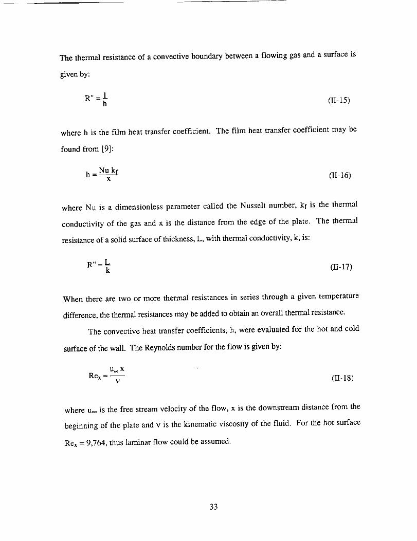
The thermalresistanceof aconvectiveboundarybetweena flowing gasanda surfaceis
givenby:
Rtt _ !
h (11-15)
where h is the film heat transfer coefficient. The film heat transfer coefficient may be
found from [9]:
h = Nu kfx (I1-16)
where Nu is a dimensionless parameter called the Nusselt number, kf is the thermal
conductivity of the gas and x is the distance from the edge of the plate. The thermal
resistance of a solid surface of thickness, L, with thermal conductivity, k, is:
gll _ L
k (1-I-17)
When there are two or more thermal resistances in series through a given temperature
difference, the thermal resistances may be added to obtain an overall thermal resistance.
The convective heat transfer coefficients, h, were evaluated for the hot and cold
surface of the wall. The Reynolds number for the flow is given by:
U._ XRex -
v (II-18)
where uoo is the free stream velocity of the flow, x is the downstream distance from the
beginning of the plate and v is the kinematic viscosity of the fluid. For the hot surface
Rex = 9,764, thus laminar flow could be assumed.
33
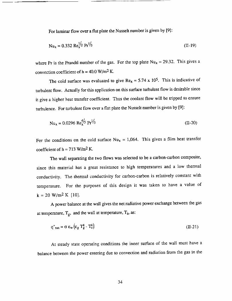
Forlaminarflow over a flat plate the Nusselt number is given by [9]:
Nut = 0.332 Re]/2 prl/3(II-19)
where Pr is the Prandtl number of the gas. For the top plate Nux = 29.32. This gives a
convection coefficient of h = 40.0 W/m 2 K.
The cold surface was evaluated to give Rex = 5.74 x 10⁵. This is indicative of
turbulent flow. Actually for this application on this surface turbulent flow is desirable since
it give a higher heat transfer coefficient. Thus the coolant flow will be tripped to ensure
turbulence. For turbulent flow over a flat plate the Nusselt number is given by [9]:
Nux = 0.0296 Re4x/5 Prl/3 (II-20)
For the conditions on the cold surface Nux = 1,064. This gives a film heat transfer
coefficient of h = 713 W/m 2 K.
The wall separating the two flows was selected to be a carbon-carbon composite,
since this material has a great resistance to high temperatures and a low thermal
conductivity. The thermal conductivity for carbon-carbon is relatively constant with
temperature. For the purposes of this design it was taken to have a value of
k = 20 W/m 2 K [10].
A power balance at the wall gives the net radiative power exchange between the gas
at temperature, Tg, and the wall at temperature, Ts, as:
q"net = o ew (eg "lag_ T_s) (I1-21)
At steady state operating conditions the inner surface of the wall must have a
balance between the power entering due to convection and radiation from the gas in the
34
absorptionchamberandthepowerleavingthroughthewall.
thatmustbesolvedfor thewall temperatureis:
Thustheresultingequation
Tw- T4R1 + _ Ew(egT_" T_s)- R22+R3 (II-22)
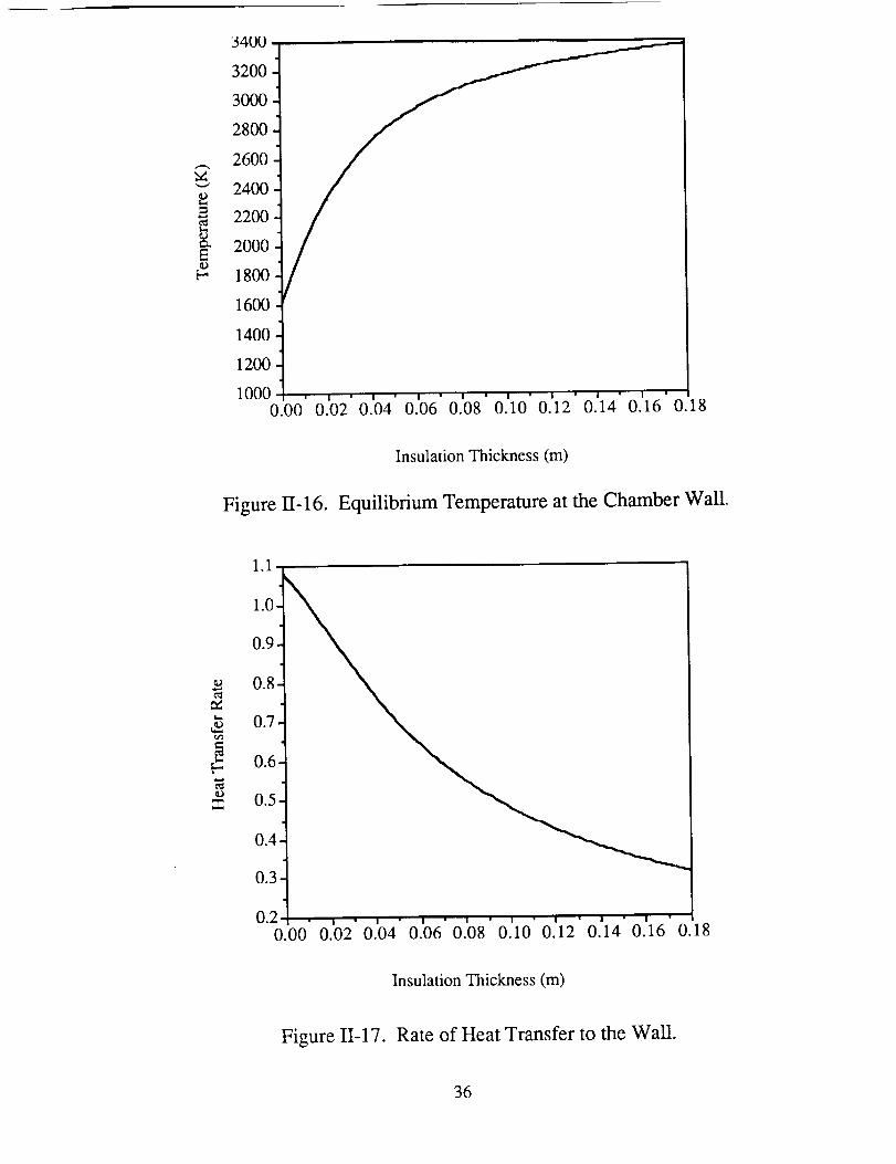
Thesolutionfor this equationwith varyingvaluesof L, thethicknessof the insulation,is
shownin Fig. II-16. The correspondingheattransferratesareshownin Fig. I1-17. A
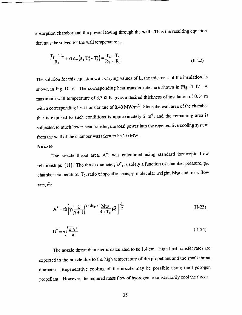
maximumwall temperatureof 3,300K givesadesiredthicknessof insulationof 0.14m
with acorrespondingheattransferrateof 0.40MW/m2. Sincethewall areaof thechamber
that is exposedto suchconditions is approximately2 m2, and the remaining areais
subjectedto muchlowerheattransfer,thetotalpowerinto theregenerativecoolingsystem
from thewall of thechamberwastakento be1.0MW.
Nozzle
The nozzle
relationships [11].
throat area,A*, was calculated using standard isentropic flow
Thethroatdiameter,D*, is solelyafunction of chamberpressure,Pc,
chambertemperature,Tc, ratioof specificheats,7, molecular weight, MW and mass flow
rate, _:
-LA* " [ /--2---_{'t_ _)II__) MW pc2 2 (II-23)
= m [_'17 +1J Ru Te
D* = _ (II-24)
The nozzle throat diameter is calculated to be 1.4 cm. High heat transfer rates are
expected in the nozzle due to the high temperature of the propellant and the small throat
diameter. Regenerative cooling of the nozzle may be possible using the hydrogen
propellant. However, the required mass flow of hydrogen to satisfactorily cool the throat
35
34UU ,
3200 t
2
g
1600
1400
1200
1000 . , . , . , . , . , • , . , . , .0.00 0.02 0.04 0.06 0.08 0.10 0.12 0.14 0.16 0.18
Insulation Thickness (m)
Figure II-16. Equilibrium Temperature at the Chamber Wall.
t_IDZZ
0.7
0.6
0.5
0.4
0.3
0.20.00 0.02 0.04 0.06 0.08 0.10 0.12 0.14 0.16 0.18
Insulation Thickness (m)
Figure 11-17. Rate of Heat Transfer to the Wall.
36
mayexceedtherequiredmassflow for propulsion.In this case,film cooling, transpiration
cooling, or a closed loop heat exchanger with radiators would be necessary.
The nozzle throat, which is constructed of the same material as the chamber, must
be more heavily reinforced to prevent bending and buckling [12]. This may be
accomplished by increasing the thickness of the nozzle material to form a cylindrical shell at
the throat as shown in Fig. 11-14.
Window
As shown in Fig. I1-14 the window diameter is 0.64 m. This is the minimum
aperture diameter necessary to deliver the required power to the absorption chamber. As
shown previously in Fig. I1-10 the intensity is not constant across the window it reaches a
maximum of 24 MW/m 2 at the center of the window and drops off toward the edges. The
window must be able to transmit the solar spectrum with a minimum amount of absorption
In addition, the window must withstand the stresses imposed by the high chamber pressure
and minimize reflection losses due to the curved surface.
Sapphire (A120 3) is a good transmitter of radiation from 0.25 p.m to 6.0 g.m and
has an absorption coefficient of approximately l%/cm. Sapphire also has the necessary
compressive strength, as shown in Table 1I-2, to effectively support the pressure load.
However, sapphire also reflects approximately 13% of the incident solar radiation from its
two surfaces due to its high refractive index. To reduce this reflection loss a thin film
dielectric anti-reflection coating is necessary. Using suitable refractory coatings the
reflection loss per surface can be reduced to < 1% for angles of incidence up to 70 °.
37
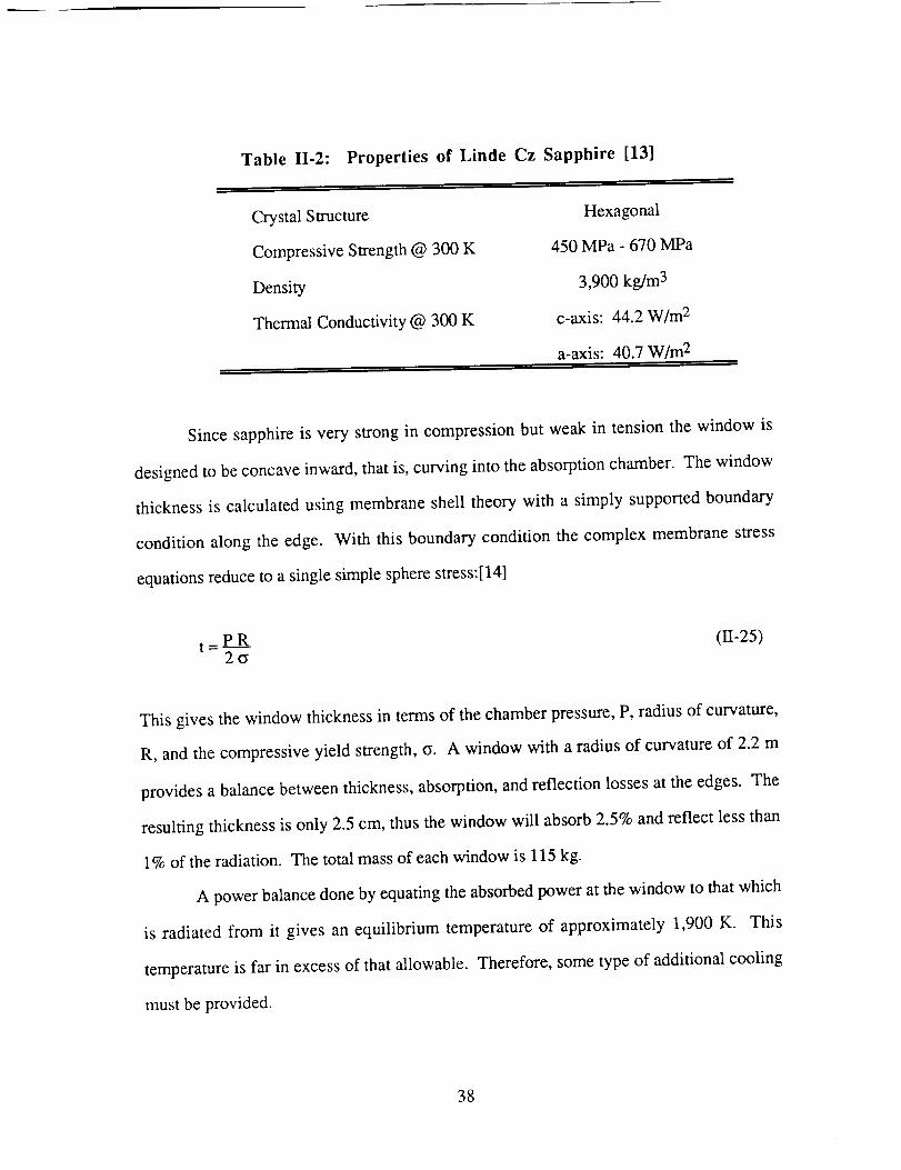
Table II-2: Properties of Linde Cz Sapphire [13]
, ,,
Crystal Structure
Compressive Strength @ 300 K
Density
Thermal Conductivity @ 300 K
Hexagonal
450 MPa - 670 MPa
3,900 kg/m 3
c-axis: 44.2 W/m 2
a-axis: 40.7 W/m 2
Since sapphire is very strong in compression but weak in tension the window is
designed to be concave inward, that is, curving into the absorption chamber. The window
thickness is calculated using membrane shell theory with a simply supported boundary
condition along the edge. With this boundary condition the complex membrane stress
equations reduce to a single simple sphere stress:[14]
t = P R (II-25)2cy
This gives the window thickness in terms of the chamber pressure, P, radius of curvature,
R, and the compressive yield strength, (y. A window with a radius of curvature of 2.2 m
provides a balance between thickness, absorption, and reflection losses at the edges. The
resulting thickness is only 2.5 cm, thus the window will absorb 2.5% and reflect less than
1% of the radiation. The total mass of each window is 115 kg.
A power balance done by equating the absorbed power at the window to that which
is radiated from it gives an equilibrium temperature of approximately 1,900 K. This
temperature is far in excess of that allowable. Therefore, some type of additional cooling
must be provided.
38
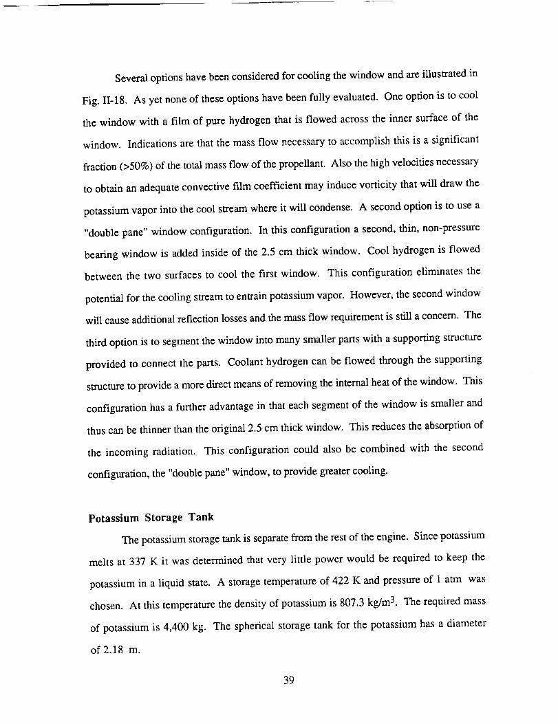
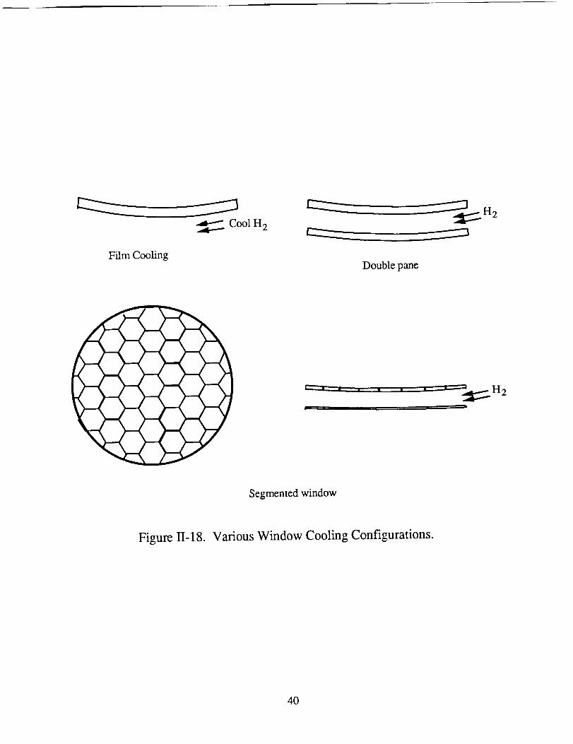
Severaloptionshavebeenconsideredfor coolingthewindow andareillustratedin
Fig. II-18. As yet noneof theseoptionshavebeenfully evaluated.Oneoption is to cool
the window with a film of pure hydrogenthat is flowed acrossthe inner surfaceof the
window. Indicationsarethat themassflow necessaryto accomplishthis is a significant
fraction(>50%)of thetotalmassflow of thepropellant.Also thehighvelocitiesnecessary
to obtainanadequateconvectivefilm coefficientmay inducevorticity thatwill draw the
potassiumvaporinto thecool streamwhereit will condense.A secondoption is to usea
"doublepane"window configuration. In this configurationa second,thin, non-pressure
bearingwindow is addedinsideof the 2.5 cm thick window. Cool hydrogenis flowed
betweenthe two surfacesto cool the first window. This configuration eliminatesthe
potentialfor thecoolingstreamto entrainpotassiumvapor. However,thesecondwindow
will causeadditionalreflectionlossesandthemassflow requirementis still aconcern.The
third option is to segmentthewindowinto manysmallerpartswith a supportingstructure
provided to connectthe parts. Coolanthydrogencanbe flowed throughthe supporting
structureto provideamoredirectmeansof removingtheinternalheatof thewindow. This
configurationhasa furtheradvantagein thateachsegmentof thewindow is smallerand
thuscanbethinnerthantheoriginal2.5cm thick window. Thisreducestheabsorptionof
the incoming radiation. This configuration could also be combined with the second
configuration,the"doublepane"window, to providegreatercooling.
Potassium Storage Tank
Thepotassiumstoragetankis separatefrom therestof theengine.Sincepotassium
meltsat 337 K it wasdeterminedthat very little power would be requiredto keep the
potassiumin a liquid state. A storagetemperatureof 422 K and pressure of 1 atm was
chosen. At this temperature the density of potassium is 807.3 kg/m 3. The required mass
of potassium is 4,400 kg. The spherical storage tank for the potassium has a diameter
of 2.18 m.
39
CoolH2
Film CoolingDoublepane
L_ • d n i I
I ___.H2
Segmented window
Figure II-18. Various Window Cooling Configurations.
40
Propellant Preheater
This subsystem is designed to vaporize the potassium and to mix the vapor with
heated hydrogen prior to injection of the propellant into the absorption chamber. The
potassium must be a dry vapor when it is injected into the absorption chamber. This
requires that it be heated to a temperature of 1,200 K [4]. If the potassium entering the
radiation receiver is not a dry vapor, then light scattering results from liquid droplets and
the overall system efficiency drops. A liquid acquisition system using small capillary tubes
is used to extract liquid potassium from the storage tank. The liquid potassium is then
pumped to a black body heat exchanger to be vaporized. This blackbody heater surrounds
the chamber window and collects the outer portion of the focal spot (Fig. II-14). The
preheater is also responsible for heating the hydrogen to an inlet temperature of 1,200 K.
The actual design of the preheater has not yet been completed. It should be a
relatively straight-forward design exercise. A flat, metal disk with machined coolant
passages for the hydrogen and potassium should suffice for this application. An
equilibrium temperature of approximately 1,400 K is desirable to obtain efficient heat
transfer to the hydrogen and potassium. The front surface of the preheater should be
anodized or otherwise coated to increase its absorptivity in the solar spectrum.
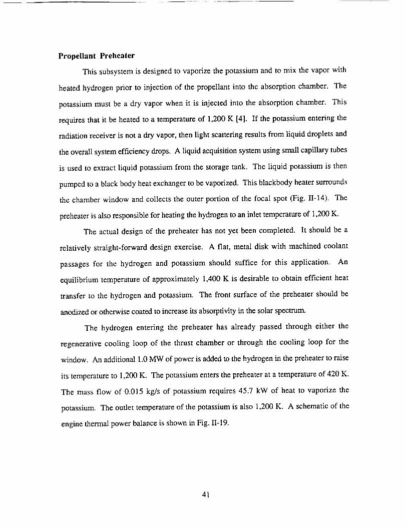
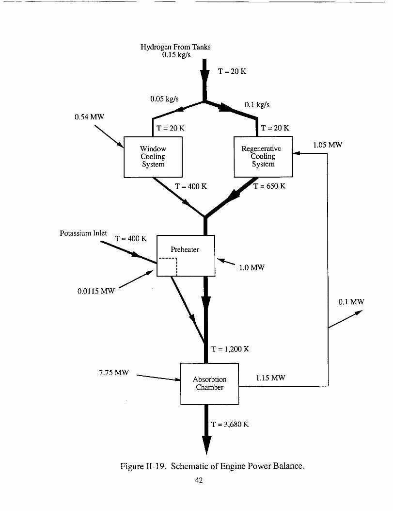
The hydrogen entering the preheater has already passed through either the
regenerative cooling loop of the thrust chamber or through the cooling loop for the
window. An additional 1.0 MW of power is added to the hydrogen in the preheater to raise
its temperature to 1,200 K. The potassium enters the preheater at a temperature of 420 K.
The mass flow of 0.015 kg/s of potassium requires 45.7 kW of heat to vaporize the
potassium. The outlet temperature of the potassium is also 1,200 K. A schematic of the
engine thermal power balance is shown in Fig. II-19.
41
HydrogenFromTanks0.15kg/s
T =20 K
0.05kg/sO.1kg/s
0.54MWT = 20K T = 20K
PotassiumInlet
Window RegenerativeCooling CoolingSystem System
= = 650K
.... _eheater
0.0115MW
1.0MW
7.75MW
T = 1,200 K
Absorbtion
Chamber
1.15 MW
1.05 MW
0.1 MW
T = 3,680 K
Figure II-19. Schematic of Engine Power Balance.
42
TRUSSES
The structure supporting each solar concentrator is made up of four triangular
trusses. The trusses connect points on the concentrator's rim to the rotary joint on the main
ship. The rotary joint allows the collector to rotate about the lateral axis to track the sun, as
discussed earlier.
The design of the truss focused mainly on providing a high stiffness to keep the
concentrator deflection within tolerance. A maximum deflection tolerance of 0.5 m was
assumed for the truss structure. Analysis was carried out using a finite element
program [15]. Pinned elements were assumed and the presence of joints to different
material between the elements was ignored for simplicity. The pinned eIements without a
different material making up the joints gives a conservative estimate of the stiffness of the
structure. Assuming that the truss is made of beam elements without joints in between each
element overestimates the structure's stiffness because the joint material has a lower
stiffness than the composite truss elements [16].
Individual Truss Members
The truss members are AS4-3502 graphite-epoxy [17] composite tubes with two
titanium end fittings bonded to the tube with a cold-hardening adhesive system [ 18]. Each
member is 5.08 cm in diameter, an unwritten NASA standard, making them easily
handleable using gloves worn by astronauts. The graphite epoxy, titanium, and adhesive
material are selected with very low, equal coefficients of thermal expansion (CTE's),
meeting NASA's CTE limits (2..5xl0-5/deg F) [19]. All truss members are clad with
aluminum in order to prevent erosion of the graphite-epoxy by atomic oxygen while in low
earth orbit [20].
Graphite-epoxy tubes clad with aluminum show good mechanical properties,
toughness, thermal/vacuum cycling stability, and tailorability of thermal-expansion
coefficient. The excellent thermal conductivity of aluminum minimizes temperature
43
differentialsaroundthecircumferenceof thetubewhenonesideis in theshadowandthe
otheris sunlit,thusminimizingthermalstresses[20].
The compositelayupsfor the tubularmembersareasfollows (defining 0 deg as
along the lengthof the tubularmember): one layer of fibers orientedat 45°, the next
at -45°, four layersat 0°, andsix additionallayerswith thesameorientations,makingthe
ply symmetric. Using the INCAP LaminateAnalysis Program [21], the modulus of
elasticityin theprincipaldirectionof themember was computed to be 9.28x10⁸ N/m 2.
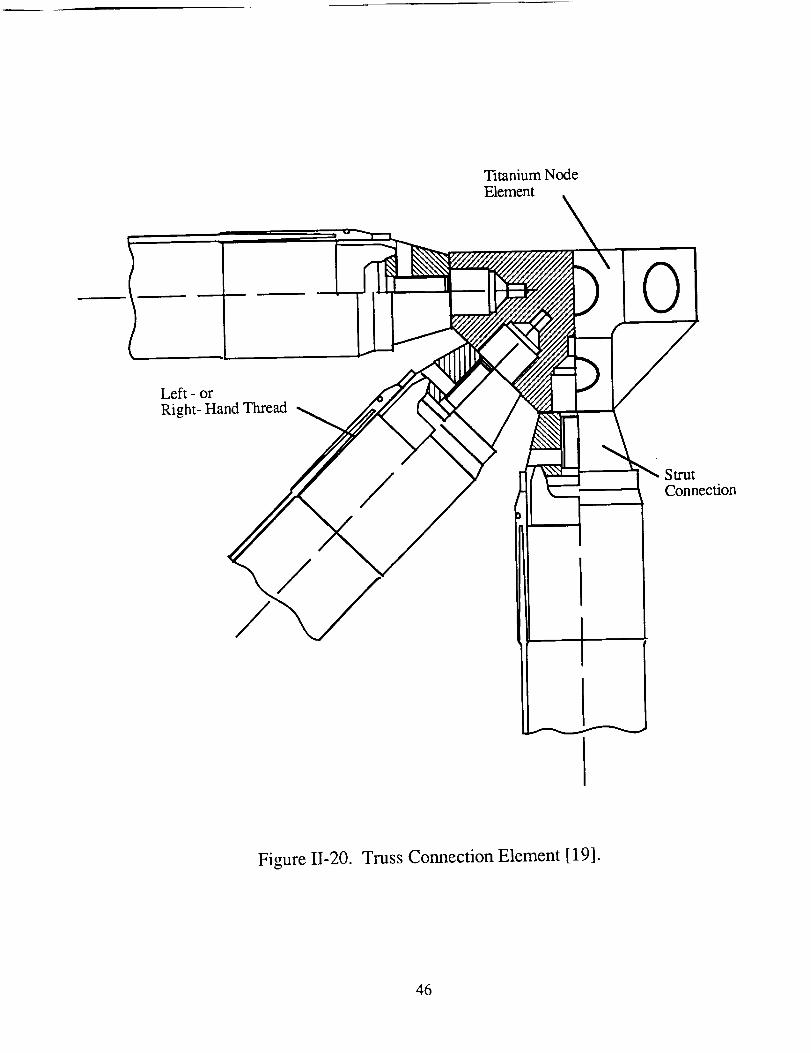
These primary structure members are connected by titanium node elements using a
right-hand thread at one end and a left-hand thread at the other end of the tube (turnbuckle
principle). This leads to very accurate regulation of the overall strut length, which enables
the attainment of the stringent alignment requirements for the complete structure [20].
Figure II-20 shows a truss connection element.
The attachment of the end fittings to the tubular members incorporates bonding of
the components in a way that leads to a continuous load transfer over the total length of the
bonding area and reduces stress peaks at the ends of the overlapping length. In addition,
the stiffness of the bonded components is balanced (the product of Young's modulus times
material thickness is equal for both components at comparable locations), which leads to a
symmetric stress distribution over the overlapping length. Increased adhesive layer
thickness at the ends of the overlapping length leads to a further reduction of the stress
peaks at these locations [ 18].
Truss Analysis
Loads causing failure were looked at with respect to the number of composite plies
in a member. Using INCAP to determine the maximum tensile loads, with Eq. II-26 and
44
Eq.II-27 to determinemaximumcompressive loads, the number of plies to prevent failure
in any member were determined.
P¢_it = 1t2EI/12 (II-26)
I = _(rt)2t (II-27)
where Pcrit is the critical compressive load applied to cause member failure, E is the
modulus of elasticity of the composite in the member's axis (9.28x10⁸ N/m2), I is the
tube's moment of inertia along its axis, r t is the tube's radius, and t is the thickness of the
member (based on one ply having a thickness of 1.524 mm) [16] An additional factor of
safety of 1.5 was utilized. After considering several possible mass configurations, a design
was found to meet the deflection tolerances. The configuration changes were limited to
element wall thickness, mass depth, and number of elements. The diameter of the rotary
joint was held constant. The mass of the final truss configuration is 3,890 kg for both
collectors.
A dynamic analysis of the structure showed that the fundamental mode of the
system is torsional. The natural frequency of the present configuration is 0.65 Hz. A
desired frequency is approximately 1 Hz [22]. Stiffening of the individual elements or
changing the mass cross section to increase the natural frequency will increase the mass of
the trusses greatly, because it was found that the frequency is relatively insensitive to these
changes. Increasing the diameter of the rotary joint and truss base would increase the
polarmoment of inertia and should prove more effective in raising the natural frequency of
the truss structure to the desired value. This will also reduce the deflection of the
concentrators.
45
TitaniumNodeElement
0
Left - or
Right- Hand Thread
Strut
Connection
Figure 11-20. Truss Connection Element [19].
46
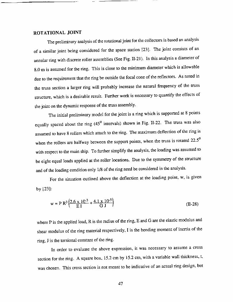
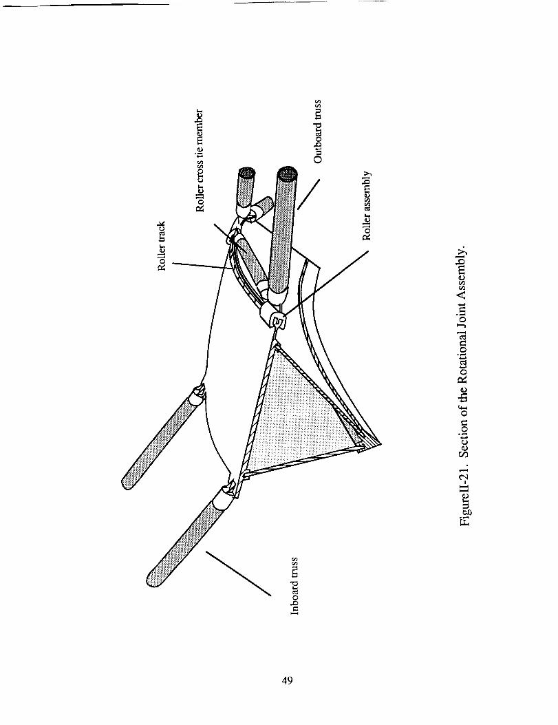
ROTATIONAL JOINT
Thepreliminaryanalysisof therotationaljoint for thecollectorsis basedananalysis
of a similar joint being considered for the space station [23]. The joint consists of an
annular ring with discrete roller assemblies (See Fig. II-21). In this analysis a diameter of
8.0 m is assumed for the ring. This is close to the minimum diameter which is allowable
due to the requirement that the ring be outside the focal cone of the reflectors. As noted in
the truss section a larger ring will probably increase the natural frequency of the truss
structure, which is a desirable result. Further work is necessary to quantify the effects of
the joint on the dynamic response of the truss assembly.
The initial preIiminary model for the joint is a ring which is supported at 8 points
equally spaced about the ring (45 ° intervals) shown in Fig. II-22. The truss was also
assumed to have 8 rollers which attach to the ring. The maximum deflection of the ring is
when the rollers are halfway between the support points, when the truss is rotated 22.5 °
with respect to the main ship. To further simplify the analysis, the loading was assumed to
be eight equal loads applied at the roller locations. Due to the symmetry of the structure
and of the loading condition only 1/8 of the ring need be considered in the analysis.
For the situation outlined above the deflection at the loading point, w, is given
by [231:
(n-28)
where P is the applied load, R is the radius of the ring, E and G are the elastic modulus and
shear modulus of the ring material respectively, I is the bending moment of inertia of the
ring, J is the torsional constant of the ring.
In order to evaluate the above expression, it was necessary to assume a cross
section for the ring. A square box, 15.2 cm by 15.2 cm, with a variable wall thickness, t,
was chosen. This cross section is not meant to be indicative of an actual ring design, but
47
wasusedto obtainreal valuesfor thedeflectionandmassof thering.
sectiontheexpressionbelowapply:
I =(0"152 + 04- (0.152- t) 4
For such a cross
0.134 (11-29)
J = (0.152-03 t (II-30)
The material for the ring was assumed to be aluminum (E = 70,000 MPa,
p = 2,700 kg/m3). The radius of the ring is 4.0 m.
The applied load was calculated by considering the maximum moment applied to the
ring by the truss and reflector assembly. Each truss and reflector has a mass of
approximately 2,500 kg. The maximum acceleration of the ship is 0.2 m/s 2. The center of
mass of the reflector assembly was assumed to be 40 m from the ring. This gives a
maximum applied moment of 20,000 N-m. If this moment is resisted by two equal forces
acting at opposite sides of the ring, each of the forces has a magnitude of 2,500 N. This is
much higher that the real loading condition in which the moment is supported by each of
the supports, but was used to obtain a conservative estimate of the necessary ring
thickness.
A maximum deflection of 1 mm was selected since such a displacement will cause a
negligible displacement of the reflectors (< 1 cm). For the given conditions a ring
thickness of 3 mm gives a maximum displacement of 0.85 mm. Such a ring, with the
given cross section, has a mass of 123 kg.
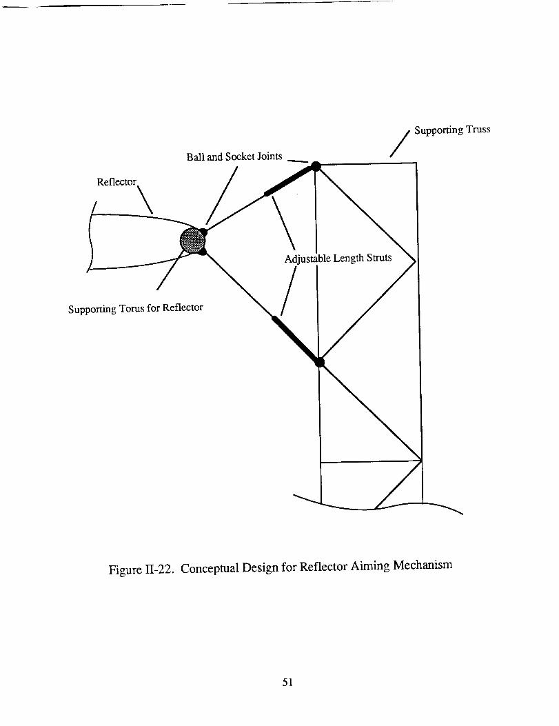
Reflector Aiming Mechanism
Since the reflectors are located on the ends of a flexible support structure, it is
recognized that some type of aiming mechanism will be necessary to correctly focus the
reflectors on the engine chamber. The maximum deflection of the center of the reflector
was specified to be 1 m. To correct for such a deflection it is necessary to rotate the
48
0
c_
0
©
!
0
0
0
0
0o_ml4
olJ_
0
49
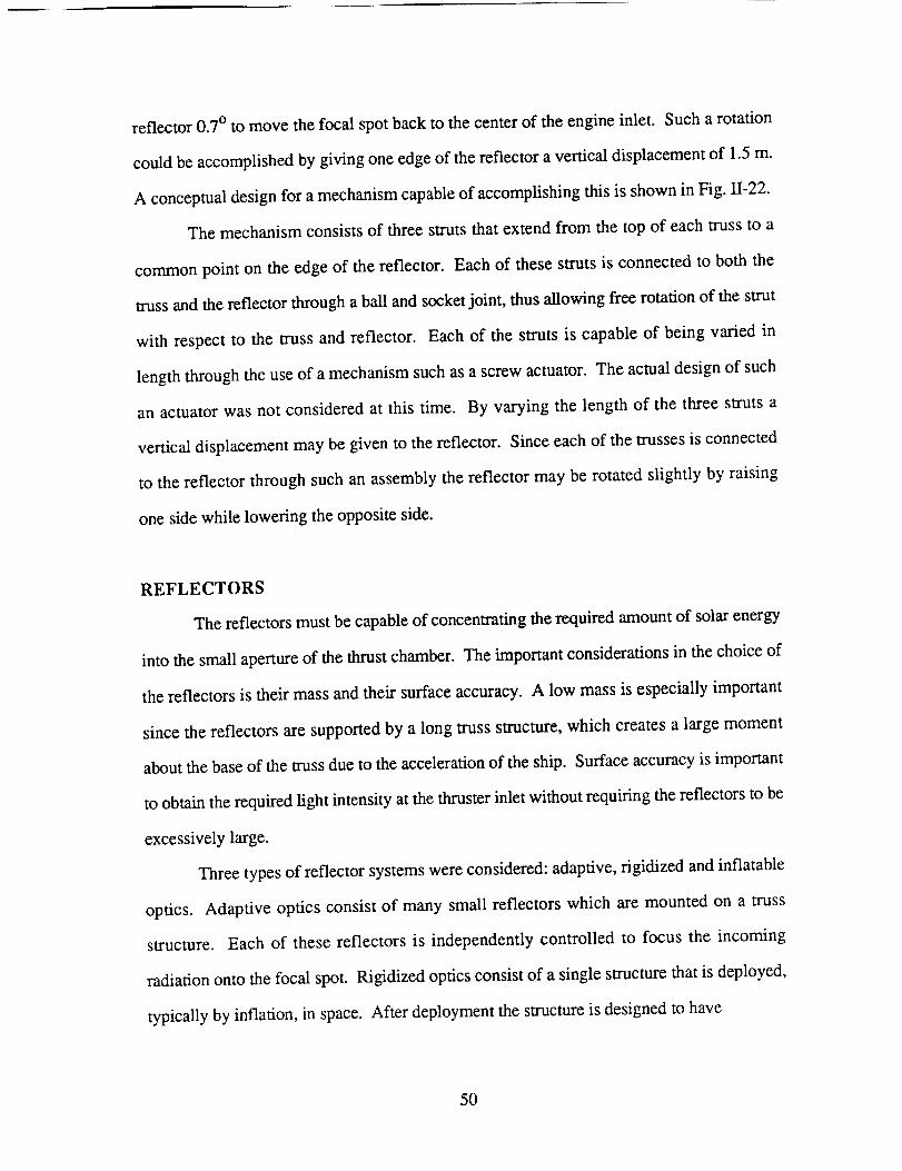
reflector 0.7 ° to move the focal spot back to the center of the engine inlet. Such a rotation
could be accomplished by giving one edge of the reflector a vertical displacement of 1.5 m.
A conceptual design for a mechanism capable of accomplishing this is shown in Fig. II-22.
The mechanism consists of three struts that extend from the top of each truss to a
common point on the edge of the reflector. Each of these struts is connected to both the
truss and the reflector through a ball and socket joint, thus allowing flee rotation of the strut
with respect to the truss and reflector. Each of the struts is capable of being varied in
length through the use of a mechanism such as a screw actuator. The actual design of such
an actuator was not considered at this time. By varying the length of the three struts a
vertical displacement may be given to the reflector. Since each of the trusses is connected
to the reflector through such an assembly the reflector may be rotated slightly by raising
one side while lowering the opposite side.
REFLECTORS
The reflectors must be capable of concentrating the required amount of solar energy
into the small aperture of the thrust chamber. The important considerations in the choice of
the reflectors is their mass and their surface accuracy. A low mass is especially important
since the reflectors are supported by a long truss structure, which creates a large moment
about the base of the truss due to the acceleration of the ship. Surface accuracy is important
to obtain the required fight intensity at the thruster inlet without requiring the reflectors to be
excessively large.
Three types of reflector systems were considered: adaptive, rigidized and inflatable
optics. Adaptive optics consist of many small reflectors which are mounted on a truss
structure. Each of these reflectors is independently controlled to focus the incoming
radiation onto the focal spot. Rigidized optics consist of a single structure that is deployed,
typically by inflation, in space. After deployment the structure is designed to have
50
Ball andSocketJointsSupportingTruss
Reflector
\
Supporting Toms for Reflector
Adjustable Length Struts
/
Figure 11-22. Conceptual Design for Reflector Aiming Mechanism
51
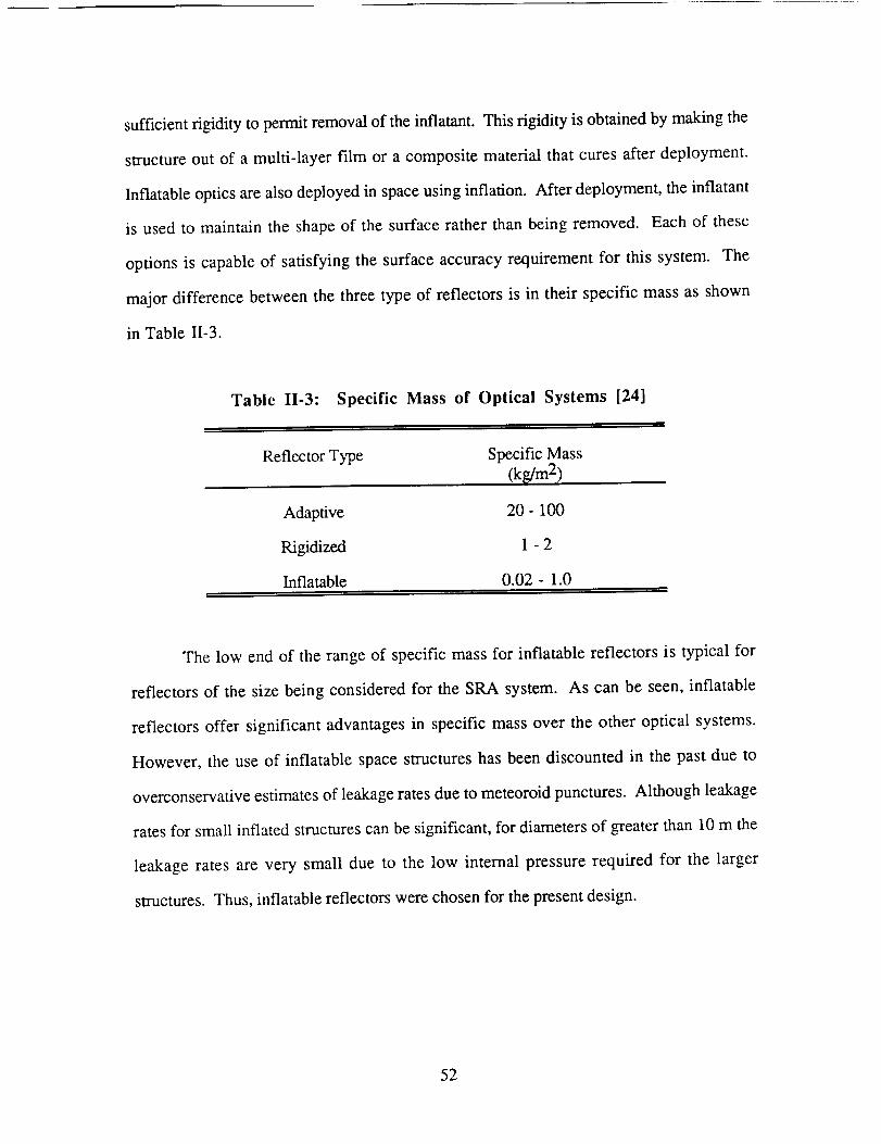
sufficientrigidity to permitremovalof theinflatant. Thisrigidity is obtainedby makingthe
structureout of a multi-layer film or a composite material that cures after deployment.
Inflatable optics are also deployed in space using inflation. After deployment, the inflatant
is used to maintain the shape of the surface rather than being removed. Each of these
options is capable of satisfying the surface accuracy requirement for this system. The
major difference between the three type of reflectors is in their specific mass as shown
in Table II-3.
Table II-3: Specific Mass of Optical Systems [24]
Reflector Type Specific Mass
(kg/m 2)
Adaptive 20- 100
Rigidized 1 - 2
Inflatable 0.02- 1.0
The low end of the range of specific mass for inflatable reflectors is typical for
reflectors of the size being considered for the SRA system. As can be seen, inflatable
reflectors offer significant advantages in specific mass over the other optical systems.
However, the use of inflatable space structures has been discounted in the past due to
overconservative estimates of leakage rates due to meteoroid punctures. Although leakage
rates for small inflated structures can be significant, for diameters of greater than 10 m the
leakage rates are very small due to the low internal pressure required for the larger
structures. Thus, inflatable reflectors were chosen for the present design.
52
Eachreflectorof the CLAM system has a surface area of 11,300 m 2. The inflatant
mass loss from each reflector can be estimated from the following formula [25]:
Am = 0.0264 _ P A t2 (II-31)
where Mw is the molecular weight of the inflatant in grams, P is the optimum pressure
(psi), A is the reflector projected area (cm2), and t is the time (years). Large reflectors are
made by joining together a large number of individual pieces called gores. The optimum
pressure (P) for such a reflector with a large number of gores is given by [25]:
p= 2W 2EG (11-32)
3(1- I.t)R D 2
where W is the maximum gore width, E G is the product of film elastic modulus and
thickness, v is Poisson's ratio of the material, R is the radius of curvature, D is the
diameter of the reflector. Depending on the material used, the optimum pressure for a
reflector of this size is less than 10 -5 psi. Using the above formulas, with hydrogen as the
inflatant at a pressure of 10 -5 psi, the loss of inflatant during one round trip (20 days) is
less than 10 -9 g. It was determined unnecessary to carry make-up inflatant during the trip
since the leakage is negligible.
The material for the reflectors, for the purpose of mass and leakage calculations, is
assumed to be 0.5 mil Tedlar (polyvinyl fluoride) with an aluminized back surface. Other
possibilities for the film surface include polyester films such as Mylar. A further study of
these materials is necessary to determine which material is best suited to the environment in
which this vehicle operates.
The reflector is supported around its circumference by a rigidized or inflated toms.
Typically, a rigidized torus is specified in the design of an inflatable reflector since an
inflatable torus has a make-up inflatant requirement of approximately 300 kg/year for a 100
53
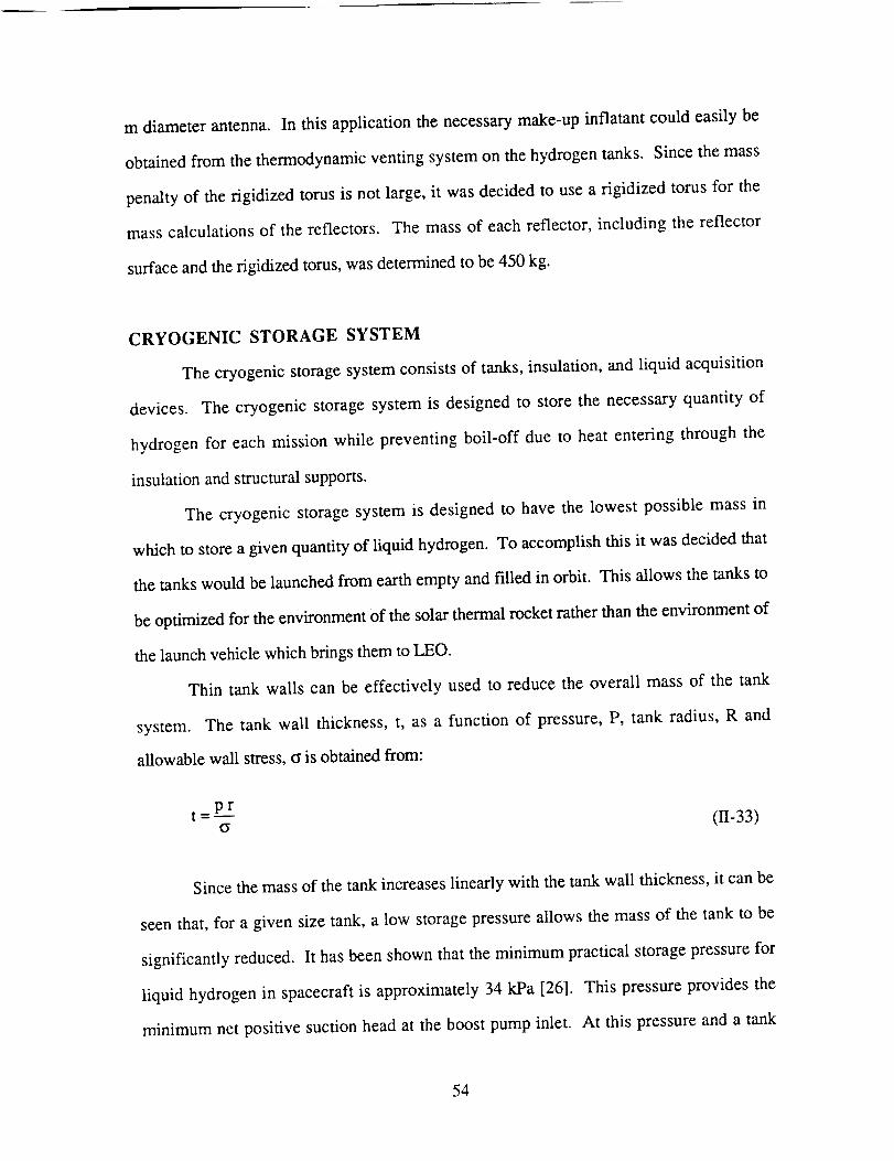
m diameterantenna. In this applicationthe necessarymake-upinflatant couldeasily be
obtainedfrom thethermodynamicventingsystemon thehydrogentanks. Sincethemass
penaltyof the rigidized tomsis not large,it wasdecidedto usea rigidized torusfor the
masscalculationsof the reflectors. The massof eachreflector, including thereflector
surfaceandtherigidizedtoms,wasdeterminedto be450kg.
CRYOGENIC STORAGE SYSTEM
Thecryogenicstoragesystemconsistsof tanks,insulation,and liquid acquisition
devices. The cryogenicstoragesystemis designedto storethe necessaryquantity of
hydrogenfor eachmissionwhile preventing boil-off dueto heatentering through the
insulationandsmacturalsupports.
The cryogenicstoragesystemis designedto havethe lowest possiblemassin
whichto storeagivenquantityof liquid hydrogen.To accomplishthis it wasdecidedthat
thetankswouldbelaunchedfrom earthemptyandIdled in orbit. This allowsthetanksto
beoptimizedfor theenvironmentof thesolarthermalrocketratherthantheenvironmentof
thelaunchvehiclewhichbringsthemto LEO.
Thin tank walls canbe effectively used to reducethe overall massof the tank
system. The tank wall thickness,t, as a function of pressure,P, tank radius, R and
allowablewall stress,_ isobtainedfrom:
t _pr
(r (11-33)
Since the mass of the tank increases linearly with the tank wall thickness, it can be
seen that, for a given size tank, a low storage pressure allows the mass of the tank to be
significantly reduced. It has been shown that the minimum practical storage pressure for
liquid hydrogen in spacecraft is approximately 34 kPa [26]. This pressure provides the
minimum net positive suction head at the boost pump inlet. At this pressure and a tank
54
radiusof 2.2 m, the tank wall thickness approaches the minimum practical thickness that
can be reliably manufactured. Therefore, reducing the pressure further does not
significantly decrease the mass of the tanks. Table 1I-4 shows the properties of hydrogen
at the selected storage conditions.
Table II.4: Hydrogen Storage Conditions
Temperature 20 K
Pressure 34 kPa
Density 70.8 k_/m 3
Due to the low density of liquid hydrogen a large volume is necessary to store a
given mass. The maximum tank diameter was set by launch constraints. Currently the
largest diameter payload bay available is the Shuttle or the planned Shuttle C. Both of these
launch vehicles have a payload bay diameter of 4.57 m. Since various supports will be
necessary around the tanks at launch a tank diameter of 4.40 m was selected.
Tank Walls
The tanks are made of 2090-T8E41 aluminum, which is an AI-Li alloy being
developed by Alcoa [27]. The properties of this material are shown in Table I1-5.
The nominal wall thickness of the tanks was determined to be 0.20 mm. The tanks
are manufactured by a process of spin forming and chem-milling in two one-piece
hemispheres. The chem-milling is done so that the tank is thicker than the nominal
thickness at the joint between the two hemispheres and at the attachment points of the
supporting struts. The joint between the two hemispheres is designed for simple
construction in space so that the tanks can be launched in a compact stowed condition. The
extemal struts that support the tank are connected to the tanks in this area. The mass of the
55
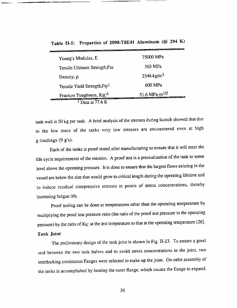
Table II-5: Properties of 2090-T8E41 Aluminum (@ 294 K)
i i ,
Young's Modulus, E 75000 MPa
Tensile Ultimate Streng_h,Ftu 565 MPa
Density, p 2546 kg/m 3
Tensile Yield Strength,Fty 1 600 MPa
Fracture Toughness, KIC ! 51.6 MPa-m 1/2
1 Data at 77.6 K
tank wall is 50 kg per tank. A brief analysis of the stresses during launch showed that due
to the low mass of the tanks very low stresses are encountered even at high
g-loadings (9 g's).
Each of the tanks is proof tested after manufacturing to ensure that it will meet the
life cycle requirements of the mission. A proof test is a pressurization of the tank to some
level above the operating pressure. It is done to ensure that the largest flaws existing in the
vessel are below the size that would grow to critical length during the operating lifetime and
to induce residual compressive stresses at points of stress concentrations, thereby
increasing fatigue life.
Proof testing can be done at temperatures other than the operating temperature by
multiplying the proof test pressure ratio (the ratio of the proof test pressure to the operating
pressure) by the ratio of KIc at the test temperature to that at the operating temperature [26].
Tank Joint
The preliminary design of the tank joint is shown in Fig. 11-23. To ensure a good
seal between the two tank halves and to avoid stress concentrations in the joint, two
interlocking continuous flanges were selected to make up the joint. On-orbit assembly of
the tanks is accomplished by heating the outer flange, which causes the flange to expand.
56
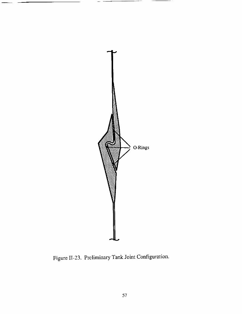
O-Rings
Figure 11-23. Preliminary Tank Joint Configuration.
57
The heatingis accomplishedby using a strip heaterwhich is placedin contactwith the
upper portion of the outer flange. An increasein radius of approximately 2 mm is
necessaryfor theinner flangetopassthroughtheouterflange. Thisrequiresatemperature
differentialof about40° C betweenthetwo flanges.A totalenergyinputof lessthan10kJ
is necessaryto achievethis temperaturedifference,thusheaterpowerof lessthan500W
shouldbesufficient. After the inner flange is in place, the outer flange is allowed to cool
while the position of the inner flange is maintained. Several O-rings are used in the joint to
provide the necessary sealing between the two pans. The location of the O-rings in
Fig. II-23 is representative, their optimum location and material remains to be determined.
Insulation
A fully passive insulation system consisting of multi-layer insulation and a vapor
cooled heat shield was chosen to minimize the mass of the system. Two routes exist for
heat transfer to the tanks: conduction through the supporting struts and radiation transfer
through the insulation. The struts supporting the tanks are of S-glass/epoxy composite
construction which gives the best performance in terms of thermal conductivity and
mass [281.
The multi-layer insulation system consists of a series of double aluminized Mylar
radiation shields separated by Dacron net spacers. This type of insulation system has been
used extensively in one form or another in space applications. A simplified model of the
radiation shields shows the heat transfer to be given by [9]:
(q12)N-N-l+ 1 (q12)0 (II -34)
where (q12)0 is the heat transfer with no shield, N is the number of shields and (ql2)N is
the heat transfer with N shields. As can be seen, increasing the number of shields greatly
decreases the heat transfer. The thickness of the insulation was determined by trading off
the mass of the hydrogen lost with the mass of the insulation.
58
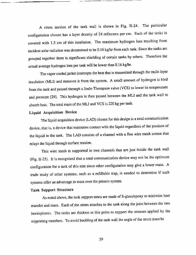
A cross section of the tank wall is shown in Fig. 11-24. The particular
configurationchosenhasa layer densityof 24 reflectorsper cm. Eachof the tanks is
coveredwith 1.5 cm of this insulation. The maximum hydrogenloss resulting from
incidentsolarradiationwasdeterminedto be0.16kg/hr from eachtank.Sincethetanksare
groupedtogetherthereis significantshieldingof certaintanksby others. Thereforethe
actualaveragehydrogenlosspertankwill belower than0.16kg/hr.
Thevaporcooledjacketinterceptstheheatthatis transmittedthroughthemulti-layer
insulation(MLI) andremovesit from the system. A small amountof hydrogenis bled
from thetankandpassedthroughaJoule-Thompsonvaive(VCS)to lower its temperature
andpressure[29]. This hydrogen is then passed between the MLI and the tank wall to
absorb heat. The total mass of the MLI and VCS is 220 kg per tank.
Liquid Acquisition Device
The liquid acquisition device (LAD) chosen for this design is a total communication
device, that is, a device that maintains contact with the liquid regardless of the position of
the liquid in the tank. The LAD consists of a channel with a fine wire mesh screen that
relays the liquid through surface tension.
This wire mesh is supported in two channels that are just inside the tank wall
(Fig. 11-25). It is recognized that a total communication device may not be the optimum
configuration for a tank of this size since other configuration may give a lower mass. A
trade study of other systems, such as a refillable trap, is needed to determine if such
systems offer an advantage in mass over the present system.
Tank Support Structure
As noted above, the tank support struts are made of S-glass/epoxy to minimize heat
transfer and mass. Each of the struts attaches to the tank along the joint between the two
hemispheres. The tanks are thickest at this point to support the stresses applied by the
supporting members. To avoid buckling of the tank wall the angle of the struts must be
59
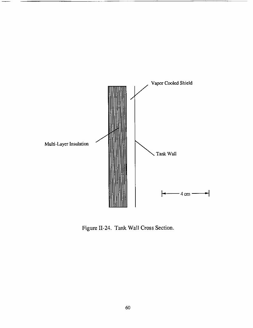
Multi-LayerInsulation
/
Vapor Cooled Shield
/
_Tank Wall
]_ 4 cm ---II
Figure I1-24. Tank Wall Cross Section.
60
LAD Channels
Figure 11-25. Liquid Acquistion Device Configuration.
61
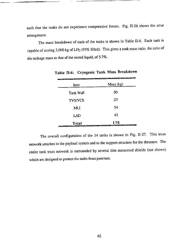
such that the tanks do not experiencecompressiveforces. Fig. II-26 showsthe strut
arrangement.
The massbreakdownof eachof the tanks is shownin Table 11-6.Each tank is
capableof storing3,000kg of LH2 (95%filled). This givesatankmassratio, theratioof
thetankagemassto thatof thestoredliquid,of 5.7%.
Table II.6: Cryogenic Tank Mass Breakdown
Item Mass (k_)
Tank Wall 50
TVS/VCS 23
MLI 54
LAD 43
Total 17 0
The overall configuration of the 14 tanks is shown in Fig. II-27. This truss
network attaches to the payload system and to the support structure for the thrusters. The
entire tank truss network is surrounded by several thin meteoroid shields (not shown)
which are designed to protect the tanks from puncture.
62
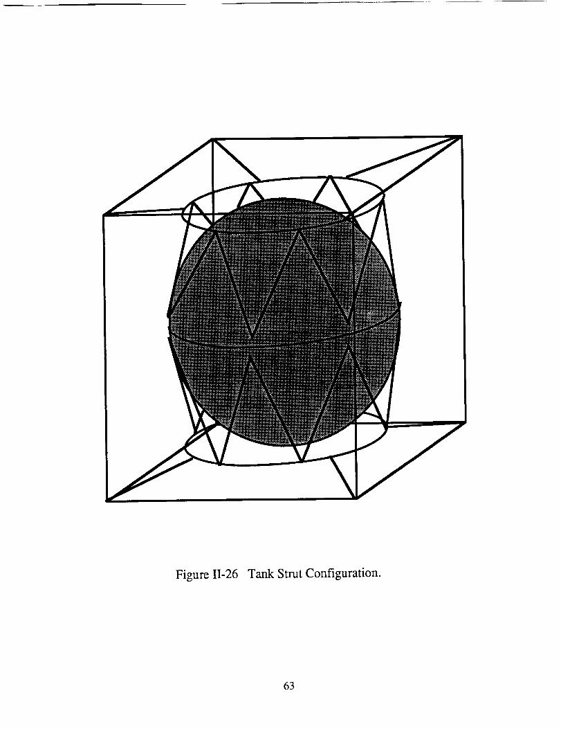
Figure 11-26 Tank Strut Configuration.
63
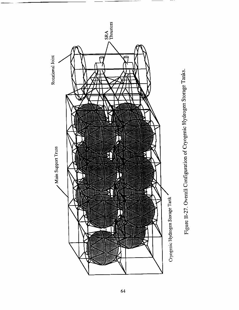
©
.o
0c_
0
0L.
0
0
0
0
c_L_
0_J
©
ol,-_
64
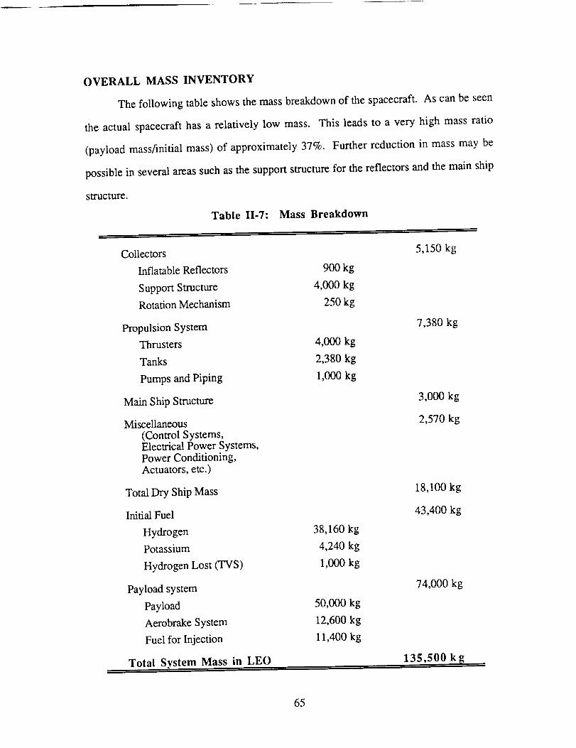
OVERALL MASS INVENTORY
The following table shows the mass breakdown of the spacecraft. As can be seen
the actual spacecraft has a relatively low mass. This leads to a very high mass ratio
(payload mass/initial mass) of approximately 37%. Further reduction in mass may be
possible in several areas such as the support structure for the reflectors and the main ship
structure.
Table II-7: Mass Breakdown
Collectors
Inflatable Reflectors
Support Structure
Rotation Mechanism
Propulsion System
Thrusters
Tanks
Pumps and Piping
Main Ship Structure
Miscellaneous
(Control Systems,Electrical Power Systems,Power Conditioning,Actuators, etc.)
Total Dry Ship Mass
Initial Fuel
Hydrogen
Potassium
Hydrogen Lost (TVS)
Payload system
Payload
Aerobrake System
Fuel for Injection
Total System Mass in LEO
5,150 kg
900 kg
4,000 kg
250 kg
7,380 kg
4,000 kg
2,380 kg
1,000 kg
3,000 kg
2,570 kg
18,100 kg
43,400 kg
38,160 kg
4,240 kg
1,000 kg
74,000 kg
50,000 kg
12,600 kg
11,400 kg
135,500 k [_
65
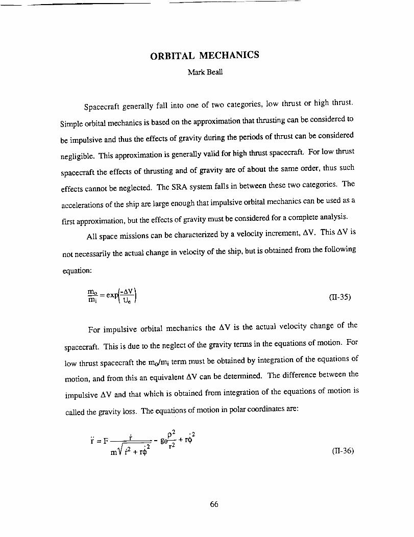
ORBITAL MECHANICS
MarkBeall
Spacecraftgenerally fall into one of two categories,low thrust or high thrust.
Simpleorbitalmechanicsis basedon theapproximationthatthrustingcanbeconsideredto
beimpulsiveandthustheeffectsof gravityduring theperiodsof thrustcanbeconsidered
neghgible.Thisapproximationis generallyvalid for highthrustspacecraft.For low thrust
spacecraftthe effectsof thrustingandof gravity areof aboutthe sameorder, thussuch
effectscannotbeneglected.TheSRA systemfalls in betweenthesetwo categories.The
accelerationsof theshiparelargeenough that impulsive orbital mechanics can be used as a
first approximation, but the effects of gravity must be considered for a complete analysis.
All space missions can be characterized by a velocity increment, AV. This AV is
not necessarily the actual change in velocity of the ship, but is obtained from the following
equation:
mo= ext_-Av /mi "_ Ue ! (II-35)
For impulsive orbital mechanics the AV is the actual velocity change of the
spacecraft. This is due to the neglect of the gravity terms in the equations of motion. For
low thrust spacecraft the mo/mi term must be obtained by integration of the equations of
motion, and from this an equivalent AV can be determined. The difference between the
impulsive AV and that which is obtained from integration of the equations of motion is
called the gravity loss. The equations of motion in polar coordinates are:
-gPr0_+r_2i: = F m3/t 2 + r(_2
(II-36)
66
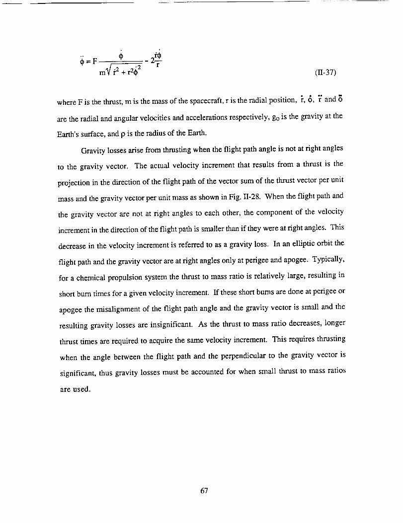
_=F _ 2_---"
m_/f2 + r2_ 2 r(11-37)
where F is the thrust, m is the mass of the spacecraft, r is the radial position, _, _, ]" and
are the radial and angular velocities and accelerations respectively, go is the gravity at the
Earth's surface, and p is the radius of the Earth.
Gravity losses arise from thrusting when the flight path angle is not at fight angles
to the gravity vector. The actual velocity increment that results from a thrust is the
projection in the direction of the flight path of the vector sum of the thrust vector per unit
mass and the gravity vector per unit mass as shown in Fig. II-28. When the flight path and
the gravity vector are not at fight angles to each other, the component of the velocity
increment in the direction of the flight path is smaller than if they were at right angles. This
decrease in the velocity increment is referred to as a gravity loss. In an elliptic orbit the
flight path and the gravity vector are at fight angles only at perigee and apogee. Typically,
for a chemical propulsion system the thrust to mass ratio is relatively large, resulting in
short bum times for a given velocity increment. If these short burns are done at perigee or
apogee the misalignment of the flight path angle and the gravity vector is small and the
resulting gravity losses are insignificant. As the thrust to mass ratio decreases, longer
thrust times are required to acquire the same velocity increment. This requires thrusting
when the angle between the flight path and the perpendicular to the gravity vector is
significant, thus gravity losses must be accounted for when small thrust to mass ratios
are used.
67
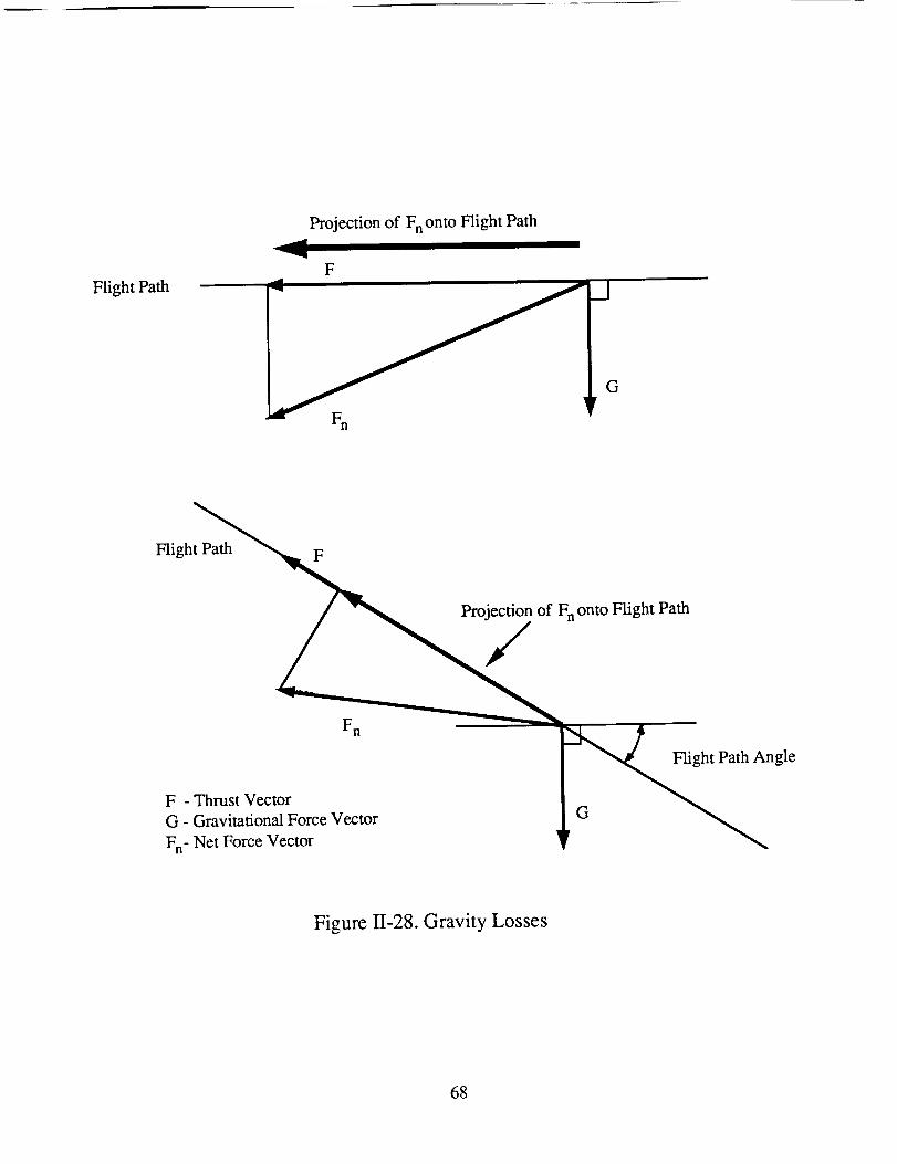
FlightPath
Projectionof FnontoFlightPath
F
FlightPath F
Projectionof FnontoFlightPath
,/
F n
F - Thrust Vector
G - Gravitational Force Vector
Fn- Net Force Vector
An' gle
Figure 1/-28. Gravity Losses
68
For the initial approximationof the SRA orbital mechanics,impulsive orbital
mechanicswere used. The spacecraftwas assumedto start in LEO with a radius
ro= 6,878km. In suchanorbit the spacecrafthasavelocity,Vcs,that is givenby:
Vcs= (II-38)
whereI.tis thegravitationalparameterof thebodyaroundwhich it is orbiting. In thiscase
= 3.986x10⁵ km3/s2. This gives the circular velocity in the initial orbit to be
Vcs= 7.61km/s. In orderto entera transferorbit to anotherplanet the spacecraftmust
acquiresufficientvelocity to escapetheearth'sgravitationalfield with anexcessvelocity,
V,,.,which is determinedby thetransferorbit to theotherplanet. The minimum energy
transferorbit to MarsrequiresVoo= 2.98km/s. From agivenorbit thevelocity necessary
to leaveearthwith aspecifiedexcessvelocityis:
vx= /v5 -2!ro (II-39)
Thus at our specified initial orbit V1 = 11.17 km/s. Thus the necessary AV to enter
into a Mars transfer orbit is 3.56 km/s. This AV can be obtained by using a series of small
thrusts at one point in the orbit rather than one single large thrust. By doing a series of
thrusts at the perigee the orbit is changed from the initial circular orbit to an elliptical one
with its perigee at the altitude of the initial circular orbit (see Fig. 11-29). This procedure is
necessary due to the low accelerations of the SRA spacecraft. There is a limit, however, to
the amount of the AV that can be obtained in this manner. If V.o is set to zero in Eq. 11-40
the escape velocity from that altitude is obtained. Any velocity above this value will result
in the spacecraft escaping earth orbit. For the initial orbit the escape velocity is
Vesc = 10.77 km/s. The importance of this figure is that there is a 0.40 km/s difference
69
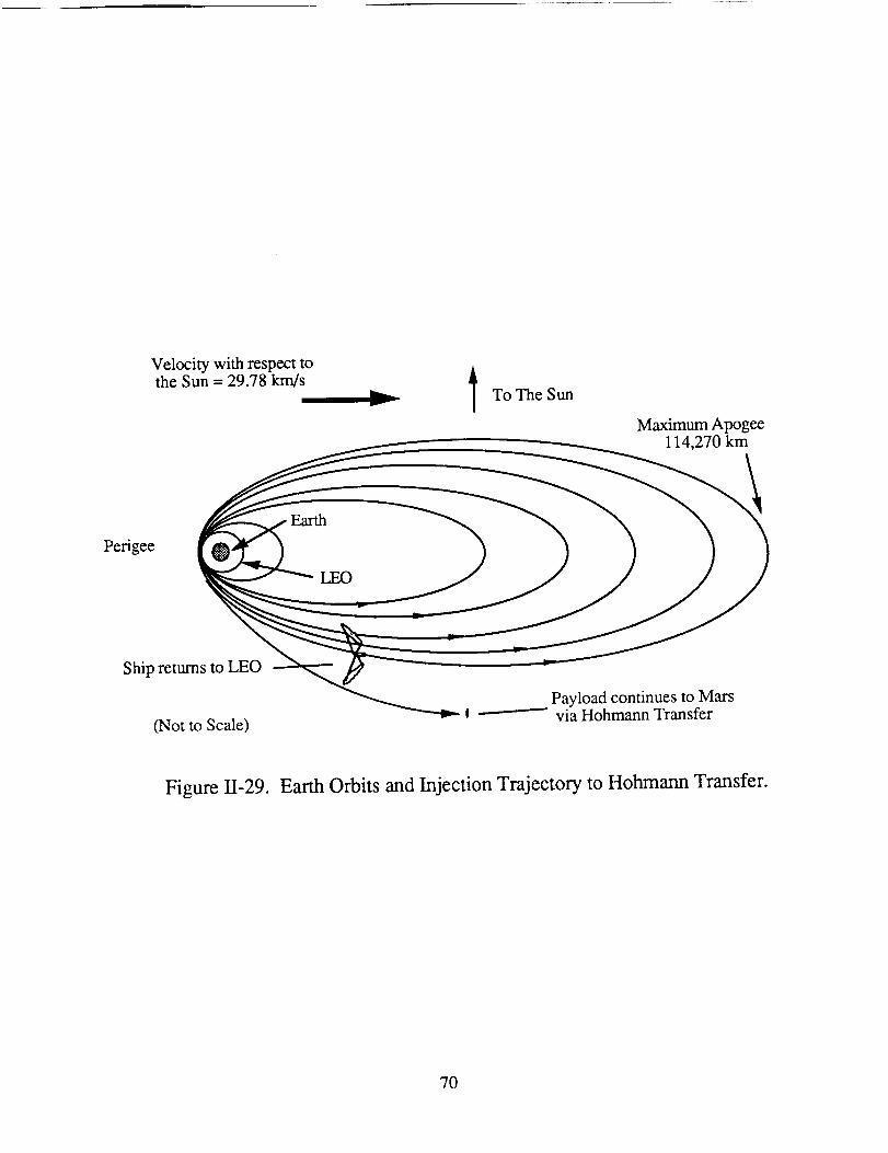
Velocitywith respecttotheSun= 29.78km/s
To TheSun
MaximumApogee114,270km
Perigee
LEO
Ship returnstoLEO
(Not to Scale)
_ Payload continues to Marsvia Hohmann Transfer
Figure II-29. Earth Orbits and Injection Trajectory to Hohmann Transfer.
70
betweenVescandV1. This difference is large enough that the SRA system cannot deliver it
in a manner that approximates an impulsive thrust since the SRA acceleration at this point is
on the order of 0.03 m/s.
At this point there are two options. First, the SRA can provide this final AV by
using a continuous thrust, until the necessary velocity is reached. Second, the payload can
be separated from the SRA propulsion unit and use a chemical rocket to impulsively gain
the required velocity increment. The first option results in a larger effective AV since the
burn time for the velocity increment is long. As the spacecraft thrusts it is getting farther
from earth resulting in a reduction in velocity. Both this reduction and the initial AV must
be gained before the required velocity is reached. The effective AV for this option is
approximately 5.5 krn/s. The second option retains the validity of the impulsive analysis
and requires the chemical system to provide a AV of 0.7 km/s. The savings in mass due to
the lower AV of the second option were determined to be greater than the mass penalty of
the chemical rocket system and thus it was chosen for this particular mission.
Multiple perigee bums over a period of approximately 19 days are used to transfer
from LEO to the separation point where the payload is released as shown in Fig. 11-30.
The separation occurs at perigee when the spacecraft has a velocity slightly less than that
required to escape the Earth's sphere of influence. After separation, the payload system,
which is discussed in detail in Appendix A, performs a short bum using a liquid chemical
propellant rocket 0-t2 - 02) to achieve the additional small velocity increment needed for a
heliocentric Hohmann transfer to Mars (Fig. 11-30). The solar propelled spacecraft does
not escape but returns to LEO for the next mission.
The actual propellant mass required was determined by estimating the initial vehicle
mass using Eq. 11-35 and then numerically integrating the full equations of motion for a
spacecraft orbiting in a gravitational field to determine a revised propellant mass
requirement. This revised propellant mass was then used recalculate the initial vehicle mass
71
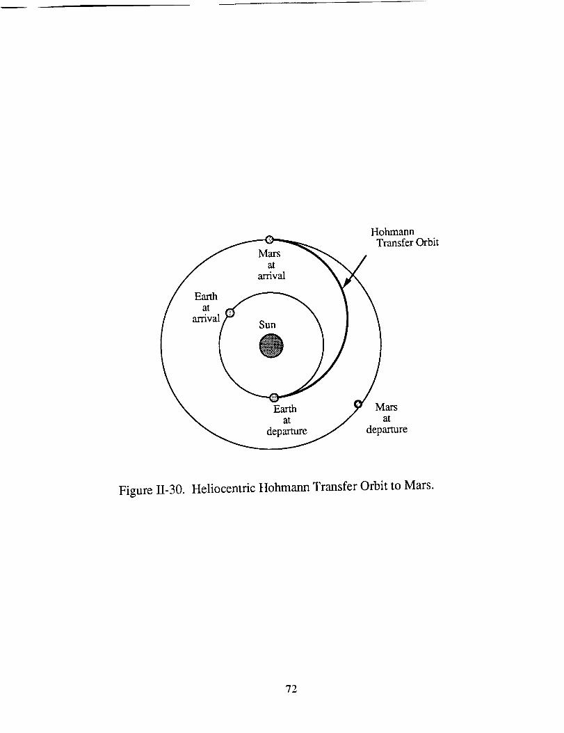
Earthat
arrival
Mars
at
arrival
Sun
@
HohmannTransfer Orbit
Earth Marsat at
departure departure
Figure II-30. Heliocentric Hohmann Transfer Orbit to Mars.
72
andtheintegrationwasrepeateduntil afinal propellantmasswasdetermined.This iterative
processresultedin apropellantmassof 42,400kg.
Thenumericalintegrationof theequationsof motionshowedthattheoptimumburn
patternwasonethatstartedwith relativelysmallburnangles(theanglerelativeto perigee)
which increaseasthe orbit becomesmoreeccentric. The thrust of the ship must be
vectoredslightly inward (towardtheEarth)duringthrustingto avoidraisingtheperigeeof
theorbit. Theactualoptimumangleis afunctionof positionin theorbit. Theprogramthat
wasusedto determinetheorbitsdid notallow thethrustangleto bevariedwith positionin
theorbit. This resultedin theperigeeincreasingslightly with eachrevolution. A small
increasein perigeewasdeterminedto benecessaryto avoidcontinuouspassesthroughthe
congestedareaof LEO, sothis constraintdid not posea major problem. Thenumerical
investigationof theorbitalmechanicsshowedthatthegravity lossesarequitesmall,on the
orderof 0.2km/s. Also, theamountof propellantconsumedandthetimerequiredto enter
the injection orbit are not very sensitiveto the durationof the burns aroundwhat was
determinedto betheoptimumburnprofile. Theresultingorbit is shownin Table11-8.
A chemicalrocket is usedto achievethefinal velocity incrementto escapefrom
Earthasdiscussedearlier. This chemicalrocketgivesthepayloada AV of 0.7 kin/s: 0.3
km/sto achieveescapevelocity and0.4km/sto sendthepayloadon theHohmanntransfer.
Thisapproachoffersthreeadvantages:
(1) Thetimeto escapeEarthis reduced.Therelativelylargethrustto massratioof
chemicalrocketallowsanearlyimpulsivefinal velocity change.Without the
chemicalrocket it would benecessaryto travel throughnumerouselliptical
orbitswith periodsof morethan2 days,therebygreatlyincreasingthetimeto
escapeEarth.
73
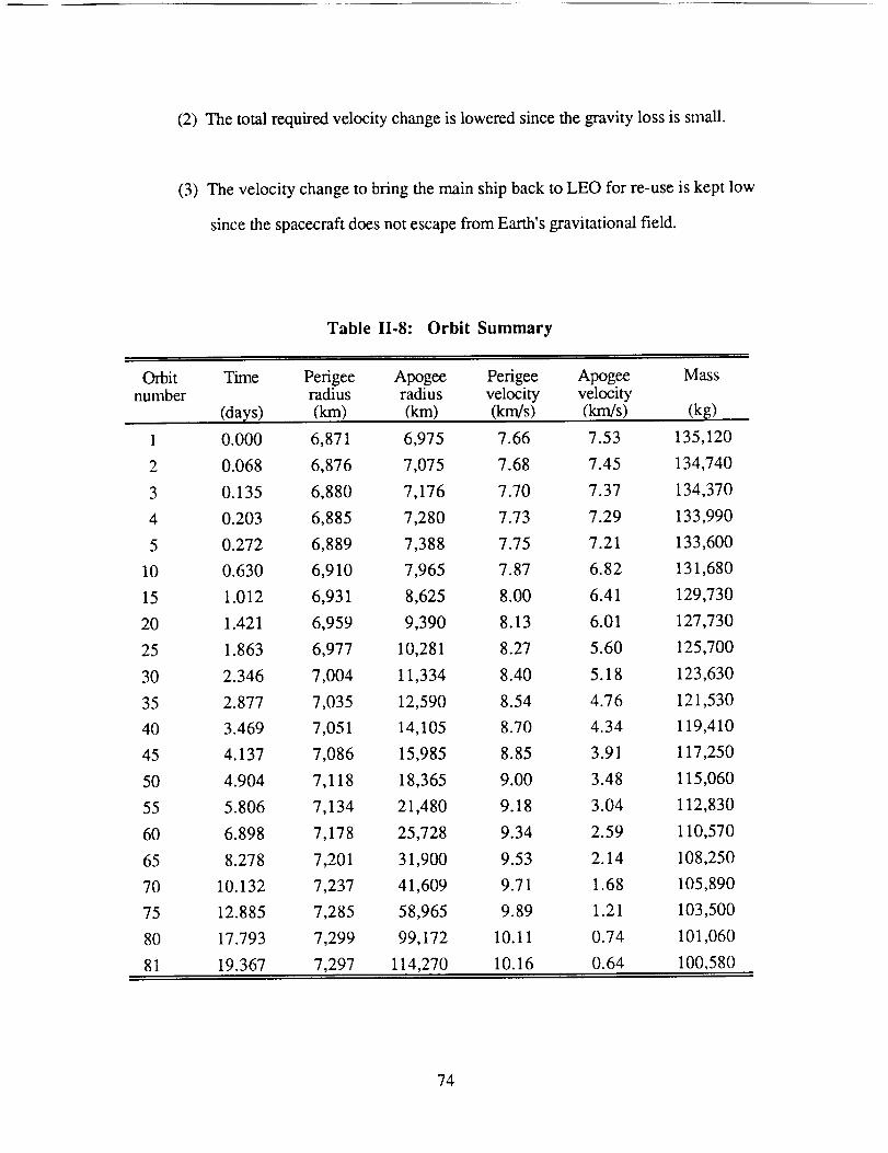
(2) Thetotal requiredvelocitychangeis loweredsincethegravitylossis small.
(3) Thevelocity changeto bring themain shipbackto LEO for re-useis kept low
sincethespacecraftdoesnotescapefrom Earth'sgravitationalfield.
Table 11.8: Orbit Summary
Orbit Time Perigee Apogee Perigee Apogeenumber radius radius velocity velocity
(days) (km) (km) (km/s) (km/s)
1 0.000 6,871
2 0.068 6,876
3 0.135 6,880
4 0.203 6,885
5 0.272 6,889
10 0.630 6,910
15 1.012 6,931
20 1.421 6,959
25 1.863 6,977
30 2.346 7,004
35 2.877 7,035
40 3.469 7,051
45 4.137 7,086
50 4.904 7,118
55 5.806 7,134
60 6.898 7,178
65 8.278 7,201
70 10.132 7,237
75 12.885 7,285
80 17.793 7,299
81 19.367 7,297
6,975 7.66 7.53
7,075 7.68 7.45
7,176 7.70 7.37
7,280 7.73 7.29
7,388 7.75 7.21
7,965 7.87 6.82
8,625 8.00 6.41
9,390 8.13 6.01
10,281 8.27 5.60
11,334 8.40 5.18
12,590 8.54 4.76
14,105 8.70 4.34
15,985 8.85 3.91
18,365 9.00 3.48
21,480 9.18 3.04
25,728 9.34 2.59
31,900 9.53 2.14
41,609 9.71 1.68
58,965 9.89 1.21
99,172 10.11 0.74
114,270 10.16 0.64
Mass
(kg)
135,120
134,740
134,370
133,990
133,600
131,680
129,730
127,730
125,700
123,630
121,530
119,410
117,250
115,060
112,830
110,570
108,250
105,890
103,500
101,060
100,580
74
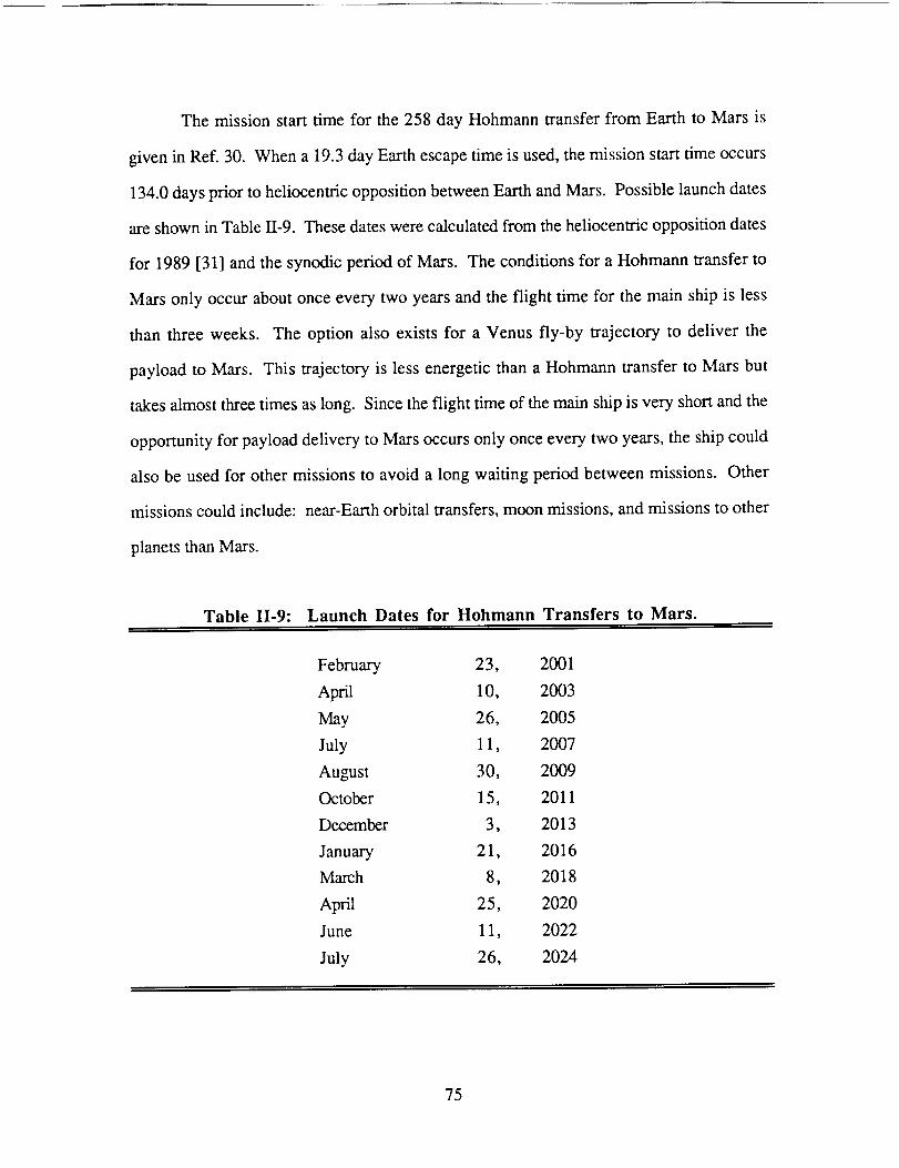
The missionstart time for the258 day Hohmanntransferfrom Earth to Mars is
givenin Ref.30. Whena 19.3dayEarthescapetimeis used,themissionstarttimeoccurs
134.0daysprior to heliocentricoppositionbetweenEarthandMars. Possiblelaunchdates
areshownin Table11-9.Thesedateswerecalculatedfrom theheliocentricoppositiondates
for 1989[31] andthesynodicperiodof Mars. Theconditionsfor aHohmanntransferto
Mars only occuraboutonceeverytwo yearsandtheflight time for the main ship is less
than three weeks. The option also exists for a Venus fly-by trajectory to deliver the
payloadto Mars. This trajectoryis lessenergeticthana Hohmanntransferto Marsbut
takesalmostthreetimesaslong. Sincetheflight timeof themainshipis veryshortandthe
opportunityfor payloaddeliveryto Marsoccursonly onceeverytwo years,theshipcould
alsobe usedfor othermissionsto avoida long waiting periodbetweenmissions. Other
missionscould include: near-Earthorbital transfers,moonmissions,andmissionsto other
planetsthanMars.
Table II-9: Launch Dates for Hohmann Transfers to Mars.
February 23, 2001
April 10, 2003
May 26, 2005
July 11, 2007
August 30, 2009
October 15, 2011
December 3, 2013
January 21, 2016
March 8, 2018
April 25, 2020
June 11, 2022
July 26, 2024
75
CONCLUSION
RonaldTeeter
TheSRApropulsionsystemis designedto delivera 50,000kg payloadfrom LEO
to low Mars orbit in undera year. It concentrates16.3MW of solar energyto heat
hydrogengasseededwith a small amountof potassiumvapor anddevelops2,940N of
thrust at a specific impulseof 1,000s. The spacecraftusesmultiple perigeeburns to
accelerateto nearthevelocity necessaryto escapetheEarth'ssphereof influence. The
payloadsystemisreleasedandusesachemicalrockettoobtainthesmallnecessaryvelocity
incrementfor aHohmanntransferto Mars. At Marsthepayloadsystemusesaerobraking
to assistin enteringlow Marsorbit.
The solar thermal propelled spacecraft is a viable concept, assuming the
infrastructureis in placeto constructlarge spacevehiclesandthat severalchallenging
technicalproblemscanbesolved. Theseincludeconstructionandcooling of thethruster
window,cooling thenozzlethroat,controlling vibration in the large truss structures, and
developing high temperature, high strength materials. Further design should be able to
reduce the mass and increase the efficiency of the system. Future work should concentrate
on improving the optical system, solving the thruster window cooling problem, advancing
the mathematical model to simulate the actual thruster behavior, detailing the heat and mass
transport characteristics of the thruster, and further defining the other subsystems. In
addition, further experimental work should be done to verify the performance of the
flowing gas volume absorber at the pressure and temperature needed in the SRA thruster.
It is assumed that the infrastructure will be in place and that the technical problems will be
solved by the year 2010, thus the SRA propulsion system could be operational by
the period 2010-2020.
76

NOMENCLATURE
A
bim
Cp
CR
D
E
f
F
go
G
h
I
Is
Isp
J
k
KIC
m
m
MW
Nu
P
Pc
Pr
PR
area
image diameter
specific heat
concentration ratio
reflector diameter
modulus of elasticity
focal length
thrust
surface gravity of earth
shear modulus
film heat transfer coefficient
moment of inertia
solar intensity
specific impulse
torsional constant
thermal conductivity
fracture toughness
mass
mass flow
molecular weight
Nusselt number
pressure
chamber pressure
Prandtl number
power
77
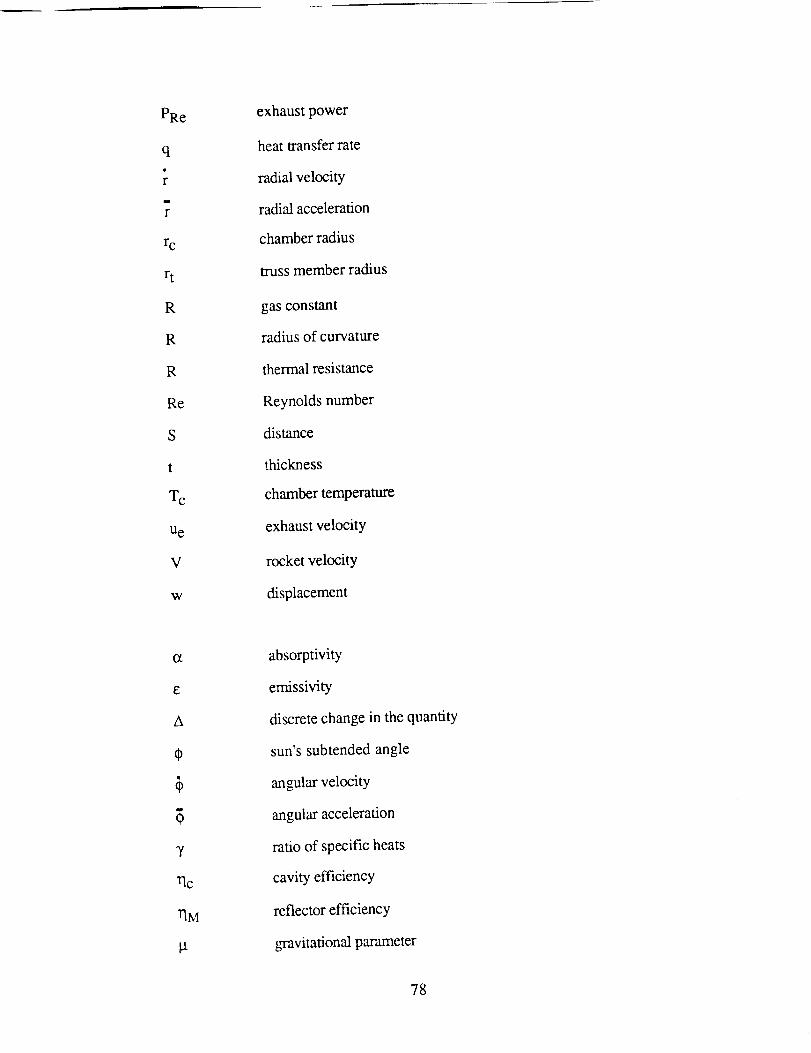
PRe
q
r
r
rc
rt
R
R
R
Re
S
t
Tc
Ue
V
W
exhaust power
heat transfer rate
radial velocity
radial acceleration
chamber radius
truss member radius
gas constant
radius of curvature
thermal resistance
Reynolds number
distance
thickness
chamber temperature
exhaust velocity
rocket velocity
displacement
E
A
7
Vlc
rim
absorptivity
emissivity
discrete change in the quantity
sun's subtended angle
angular velocity
angular acceleration
ratio of specific heats
cavity efficiency
reflector efficiency
gravitational parameter
78

I.t viscosity
v kinematic viscosity
v Poission's ratio
0 reflector focal cone angle
9 reflectivity
c Stephan-Boltzman constant
c N normal stress
Superscripts
* throat conditions
" per unit area
Subscripts
c chamber
e exit
i incoming
M reflector
N normal
o sea level
w wall
g gas
s surface
A dot above a variable ( " ) indicates a time derivative.
successive time derivatives.
All values are in MKS units.
Successive dots indicate
79
REFERENCES
o Mattick, Arthur T., "Coaxial Radiative and Convective Heat Transfer in Gray and
Nongray Gases", J. Ouant. Spectrosc. Radiat. Transfer, Vol. 24, pp. 323-334,
1980.
° Mattick A. T., Hertzberg, A., Decher, R., and Lau, C.V., "High Temperature
Solar Photon Engines", Journal of Energy, Vol. 3, pp. 30 -39, 1979.
3 Rault, D.F.G., "Radiation Energy Receiver for High Performance Energy
Conversion Cycles", Doctoral Thesis, University of Washington, 1983.
. Rault, D.F.G. and Hertzberg, A., "Radiation Energy Receiver for Laser and Solar
Propulsion Systems", AIAA Paper No. 83-1207, June, 1983.
, McFall, K., Predoctoral Research Associate, Department of Aeronautics and
Astronautics, University of Washington, private communication, March, 1989.
, Shoji, J. M., "Performance Potential of Advanced Solar Thermal Propulsion",
AIAA Paper No. 83-1307, June, 1983.
o Popov, Edgar Paul, Mechanics of Materials, Second Edition. Prentice-Hall, Inc.,
Englewood Cliffs, N.J., p. 291, 1978.
o Van Wylen, G.J. and Sonntag, R.E., Fundamentals of Classical Thermodynamics,
3rd Edition, John Wiley and Sons, Inc, 1985.
8O
o Incropera, F.P.and De Witt, D.P., Fundam_nl;_ll_ of Heat and Mass Transfer, 2nd
Edition, John Wiley and Sons, Inc, 1985.
10. Goetzel, C.G., "High-Temperature Properties of Some Carbon-Carbon
Composites", High Temperatures-High Pressures, Vol 12, p. 11-22, 1980.
11. Kuethe, Arnold M. and Chow, C.Y., Foundations of Aerodynamics, John Wiley
and Sons, Inc, New York, 1986.
12. NASA, "Liquid Rocket Engine Fluid Cooled Combustion Chambers", NASA SP-
8087, 1972.
13. "Optical Properties and Applications of Linde Cz Sapphire", Union Carbide
Technical Bulletin, 1972.
14. Young, W.C., Roark's Formulas for Stress and Strain, 6th Edition, McGraw-Hill,
1989.
15. Modifications of Finite Element Analysis Program (FEAP), Holsapple, K. A.,
Department of Aeronautic and Astronautics, University of Washington.
16. Bush, H. G., and Mikulas, M. M., "Advances in Structural Concepts", NASA CP-
2269 Part 1, May, 1983.
17. Swanson G., Gurdal, Z., and Stannes, J.H., Jr., "Structural Efficiency Study of
Graphite-Epoxy Aircraft Rib Structures," AIAA Paper No. 88-2218, April, 1988.
81
18. Franz,J. andLaube, J., "Design and Manufacturing Aspect of Tubular Carbon
Fiber Composite/Titanium Bonded Joints", Composite Structures: Elsevier
Applied Science Publishers Ltd., England, 1986.
19. Space Station Program Office, "Space Station Truss Structures and Construction
Considerations," Structures and Mechanif_ White Paper: NASA Johnson Space
Center, July ,1984.
20. Leger, L.J., Visentire, J.T., and Schliesing, J.A., "A Consideration of Atomic
Oxygen Interactions with Space Station," AIAA Paper No. 85-0476, Jan., 1985.
21. INCAP Laminate Analysis Program,The Boeing Company, Seattle WA,
Feb., 1989.
22. Mikulas M., NASA Langley Research Center, private communication,
March 1989.
23. Lake, M.S.and Bush, H.G., "An Analytical Investigation of a Conceptual Design
for the Space Station Tranverse Boom Rotary Joint Structure", NASA Langley
Research Center TM-87665, Jan., 1986.
24. Frisbee, R.H., Horvath, J.C., and Sercel, J.C., "Space-Based Laser Propulsion
for Orbit Transfer", JPL D-1919, Jet Propulsion Laboratory, Pasadena, CA, 1984.
25. Thomas, M. and Friese, G.J., "Pressurized Antennas for Space Radars", AIAA
Paper No. 80-1928, 1980.
82
26. Terre, C.N., "Low Pressure/Lightweight Cryogenic Propellant Tank for the
Space-BasedOrbital Transfer Vehicle", General Dynamics Space Systems
Division, A86-38826.
27. Glazer,J.,et al., "CryogenicMechanicalPropertiesof A1-Cu-Li-ZrAlloy 2090",
LawrenceLivermoreNational Laboratory,University of California, Livermore,
CA, 1985CryogenicEngineering/InternationalCryogenicMaterialsConference,
Cambridge,MA, Aug., 1985.
28. Eberhardt, R.N. and Fester, D.A., "Shuttle Compatible Cryogenic Liquid Storage
and Supply Systems," AIAA Paper No. 81-1509, July 1981.
29. Aydelott, J.C., Carney, M.J., and Hochstein, J.I., NASA Lewis Research Center
Low-Gravity Fluid Management Technology Program, NASA TM 87145, NASA
Lewis Research Center, Cleveland, OH, Nov., 1985.
30. Bate, R.R., Mueller, D.D., and White, J.E., Fundamentals of Astrodynamics.
Dover Publications, Inc., New York, 1971.
31. Stuhlinger, E., "The Flight Path of an Electrically Propelled Space Ship", Jet
Propulsion, Vol. 27, pp. 410-414, April 1957.
32. Astronomical Almanac fgr lh_ Y_r 19_9, U.S. Government Printing Office,
1988.
83
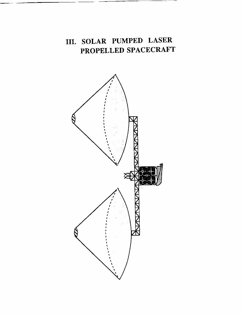
III. SOLAR PUMPED LASER
PROPELLED SPACECRAFT
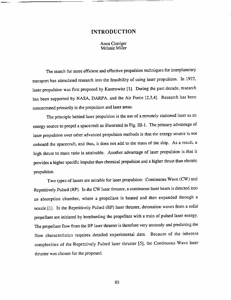
INTRODUCTION
Anna CinnigerMelanie Miller
The search for more efficient and effective propulsion techniques for interplanetary
transport has stimulated research into the feasibility of using laser propulsion. In 1972,
laser propulsion was first proposed by Kantrowitz [1]. During the past decade, research
has been supported by NASA, DARPA, and the Air Force [2,3,4]. Research has been
concentrated primarily in the propulsion and laser areas.
The principle behind laser propulsion is the use of a remotely stationed laser as an
energy source to propel a spacecraft as illustrated in Fig. III-1. The primary advantage of
laser propulsion over other advanced propulsion methods is that the energy source is not
onboard the spacecraft, and thus, it does not add to the mass of the ship. As a result, a
high thrust to mass ratio is attainable. Another advantage of laser propulsion is that it
provides a higher specific impulse than chemical propulsion and a higher thrust than electric
propulsion.
Two types of lasers are suitable for laser propulsion: Continuous Wave (CW) and
Repetitively Pulsed (RP). In the CW laser thruster, a continuous laser beam is directed into
an absorption chamber, where a propellant is heated and then expanded through a
nozzle [1]. In the Repetitively Pulsed (RP) laser thruster, detonation waves from a solid
propellant are initiated by bombarding the propellant with a train of pulsed laser energy.
The propellant flow from the RP laser thruster is therefore very unsteady and predicting the
flow characteristics requires detailed experimental data. Because of the inherent
complexities of the Repetitively Pulsed laser thruster [5], the Continuous Wave laser
thruster was chosen for the proposed.
85

Theproposedpreliminarydesignof a laser propelled spacecraft system includes a
solar pumped CO 2 laser platform, residing in LEO, that beams energy to a receiver on
board a spacecraft. Once the craft receives the laser energy, it is converted into thermal
energy and finally into thrust. The laser propulsion system includes two subsystems, the
spacecraft thrusters and the laser/optical system.
86
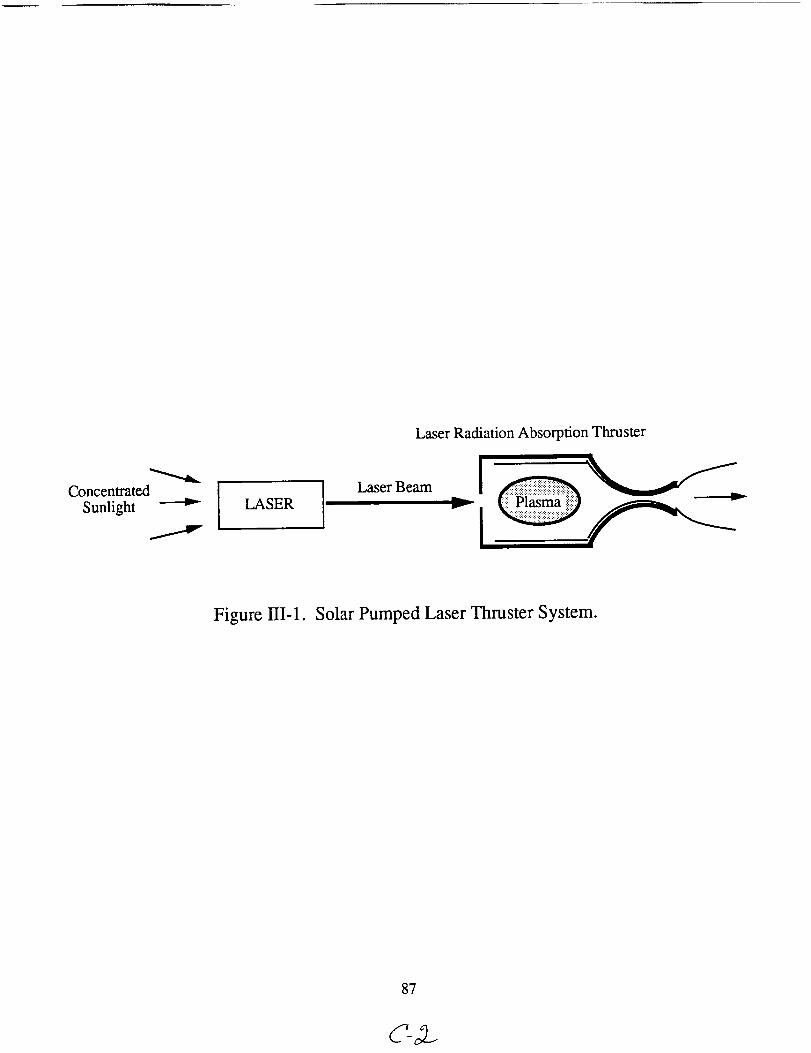
ConcentratedSunlight I LASER I
LaserBeam
LaserRadiationAbsorptionThruster
I -
Figure III-1. Solar Pumped Laser Thruster System.
87
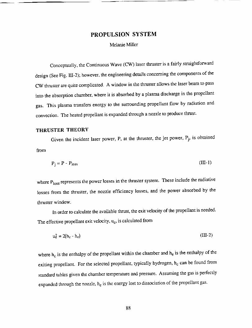
PROPULSION SYSTEM
Melanie Miller
Conceptually, the Continuous Wave (CW) laser thruster is a fairly straightforward
design (See Fig. III-2); however, the engineering details concerning the components of the
CW thruster are quite complicated. A window in the thruster allows the laser beam to pass
into the absorption chamber, where it is absorbed by a plasma discharge in the propellant
gas. This plasma transfers energy to the surrounding propellant flow by radiation and
convection. The heated propellant is expanded through a nozzle to produce thrust.
THRUSTER THEORY
Given the incident laser power, P, at the thruster, the jet power, Pj, is obtained
from
Pj = P - Ploss (III-1)
where Ploss represents the power losses in the thruster system. These include the radiative
losses from the thruster, the nozzle efficiency losses, and the power absorbed by the
thruster window.
In order to calculate the available thrust, the exit velocity of the propellant is needed.
The effective propellant exit velocity, ue, is calculated from
ue2 = 2(he- he) (III-2)
where hc is the enthalpy of the propellant within the chamber and h e is the enthalpy of the
exiting propellant. For the selected propellant, typically hydrogen, h c can be found from
standard tables given the chamber temperature and pressure. Assuming the gas is perfectly
expanded through the nozzle, h e is the energy lost to dissociation of the propellant gas.
88
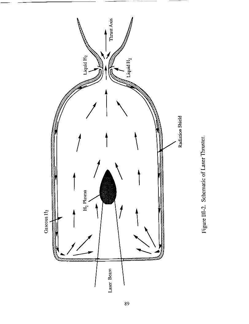
o0
=:
/
//
E
1
1
° _,,,i
o
,..a
0
o
o
!
89
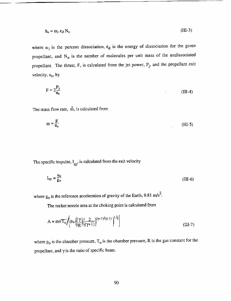
he= al ¢d No (III-3)
where cx1 is the percent dissociation, e d is the energy of dissociation for the given
propellant, and N O is the number of molecules per unit mass of the undissociated
propellant. The thrust, F, is calculated from the jet power, Pj, and the propellant exit
velocity, u e, by
F=2PJue (III-4)
The mass flow rate, _, is calculated from
ria= F---u_ (III-5)
The specific impulse, Isp, is calculated from the exit velocity
Ue
Xsp = go
where go is the reference acceleration of gravity of the Earth, 9.81 m/s 2.
The rocket nozzle area at the choking point is calculated from
A= m'(To-o/_Po ((__)[2,(__]l(v+1)/(v-1) )1/2]
(III-6)
(II/-7)
where Po is the chamber pressure, T O is the chamber pressure, R is the gas constant for the
propellant, and _, is the ratio of specific heats.
9O
CONCEPTUAL DESIGN OF LASER THRUSTER
Due to the high temperature of the propellant within the absorption chamber, the
thruster design centered around the use of regenerative cooling concepts (See Fig. III-2).
The nozzle is regeneratively cooled by the incoming liquid hydrogen. A radiation shield
surrounds the absorption chamber which is also actively cooled by the incoming hydrogen.
During the process of cooling the chamber, the hydrogen is preheated. As a result, the
efficiency of the entire thruster system is maximized.
Optimizing Propellants
Hydrogen is the optimal propellant for the laser propulsion system. Since
hydrogen has the lowest molecular weight, as a propellant, it will give the highest possible
specific impulse. A disadvantage of using hydrogen as a propellant is that, as a result of its
low density, hydrogen requires more storage volume than other propellants. Considering
these performance trade-offs, the advantages of using hydrogen propellant outweigh the
disadvantages. Eskridge, et al., confirm these findings in their
calculations [6].
Thruster Performance
Due to constraints of the feasibility of high powered lasers, the laser system is
assumed to produce 6 MW of laser energy of which 5.4 MW is received by the spacecraft
(See section: Laser and Associated Optical System). The radiative losses from the thruster
are calculated to be 0.1 MW, given that the temperature of the gas adjacent to the chamber
wall is 4,000 K. This temperature was determined from the 2-D model discussed in
Appendix B. The nozzle efficiency was assumed to be 95% which led to a power loss of
0.26 MW. The thruster window absorbed 14.8 kW of the incoming laser energy (See
subsection: Absorption Chamber Window). The resulting jet power is approximately
5 MW. The efficiency is calculated form the ratio of the exhaust power, Pj, to the
incoming laser power, P, and is approximately 93%.
91
Downstream of the plasma, the fluid mixing results in an estimated average
temperature, T o, of 4,300 K at the entrance to the nozzle [5]. The thermodynamic
properties of the hydrogen at this temperature are taken as the chamber conditions used to
calculate the engine performance. The chamber pressure, Po, is optimized to be 10 atm
(See subsection: Optimizing Chamber Pressure).
For hydrogen at the given chamber temperature and pressure, the % dissociation
was found to be 40%, which results in an exit velocity of 12,600 rn/s (Isp = 1285 s). The
corresponding mass flow rate is 0.036 kg/s, resulting in a thrust of 600 N.
DETAILED THRUSTER COMPONENT DESIGN
Absorption Chamber Design
The design of the absorption chamber begins with an estimation of the inside
diameter of the chamber. This diameter needs to be large enough so that the temperatures
of the flow adjacent to the wall will be sufficiently moderate to avoid damage of the
chamber wall. From the available data on material properties [7], the maximum permissible
temperature for an actively cooled radiation shield (See Fig. Ili-3) is assumed to be
4,000 K. The radius at which the 4,000 K isotherm is a tangent to the thruster radiation
shield was determined by calculations made from the 2-D mathematical model (See
Appendix B). The resulting absorption chamber inner diameter is 26 cm. The active
cooling duct requires approximately a 1 cm spacing between the radiation shield and the
outer chamber wall (See Fig. III-4). Therefore the outer chamber wall has an inside
diameter of approximately 28 cm.
The proposed thruster system is composed primarily of Molybdenum [7].
Molybdenum is currently used in the design of rocket chambers and heat exchangers which
require the ability to endure large thermal stresses. The use of a single material was chosen
due to the extensive thermal cycling the thruster may have to endure.
92
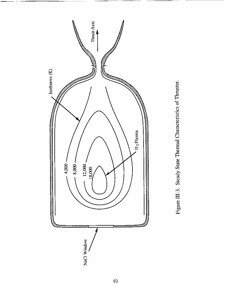
§§ §
0
r_
-_
c_
c_
c_
°1-._
93
9E
tuo 8E
tuo 0£94
For stresscalculations,theouterchamberwall wasmodeledasa cylindrical, thin-
walledpressurevessel.Thehoopstress,_, of thisouterwall iscalculatedfrom
pryG-
tw (Ir -8)
where p is the pressure differential, r v is the radius to the wall, and tw is the wall thickness.
Since the external chamber wall is actively cooled, it is estimated to reach a
maximum temperature of 1,500 K. Given the internal pressure of 10 atm, a maximum
allowable stress of 241 MPa for Molybdenum at 1,500 K, and an internal radius of 14 cm
from the thruster design, the required outer chamber wall thickness is 2.5 mm. Although
the calculated wall thickness will withstand the pressure stresses, additional stresses are
generated by the thermal gradients through the material. With a factor of safety of four, the
thickness of the outer chamber wall is 1 cm.
Optimization of Chamber Pressure
A major engine design consideration is to minimize any damage that might occur to
the thruster during the ignition of a plasma. For approximately 300 nanoseconds before
plasma formation, the nozzle area could be exposed to a large fraction of the laser radiation
directed into the absorption chamber. The solution to this problem is to direct the laser
beam in such a manner that during ignition the beam exits the nozzle throat area without
impinging on the thruster structural material (See Fig. 1II-5). By decreasing the chamber
pressure, and therefore increasing the nozzle throat area for the choked condition, a nozzle
throat area was found which is large enough to allow the beam to exit the nozzle in the
manner described. Because the materials used for the chamber walls have definite stress
limitations, an iterative process of calculating the optimum chamber pressure, wall
thickness, and position of the focal point of the incoming laser beam was also conducted.
In this manner, the chamber pressure is determined to be 10 atm, resulting in a nozzle
throat area of 3.53 cm 2.
95
oo_mq
olw_
Ec_
O
ol-i
96
Temperature Distribution within the Thruster Chamber
The temperature gradients in the absorption chamber during steady state operation
are relatively large. The plasma core has the highest temperature, and the temperature
decreases in the upstream, downstream, and radial directions. The high kinetic energy of
the molecules, ions and free electrons within the plasma raises the thermal energy of the
hydrogen gas that flows around the core (See Fig. III-2). From a 2-D mathematical model
of the thermal characteristics within the chamber [8], the plasma core temperature was
found to be 18,000 K while the hydrogen gas temperature range at the radiation shield
walls is 1,500 to 4,000 K (See Fig. III-3). The isotherms within the engine were
calculated from the thermal flux through the hydrogen [8]. By varying the chamber
pressure, mass flow rate, and laser intensity, it was possible to optimize the temperature
profile within the absorption chamber and the temperature of the plasma. At plasma
temperatures greater than 19,000 K, a significant fraction of the flow within the chamber is
dissociated, thus decreasing the efficiency of the thruster. At lower plasma temperatures,
there is less absorption of the laser energy. To optimize the energy efficiency of the
system, it is desirable to design the thruster such that the temperature of the plasma core is
approximately 18,000 K.
Absorption Chamber Window
A major problem concerning the design of a laser thruster is finding a transparent
medium that allows a 5 MW laser beam to enter the absorption chamber. The chamber
window must absorb as little of the incident laser energy as possible to minimize the
heating of the window surface, while also having the capability to structurally withstanding
the energy that it does absorb. The optimal transparent substance appears to be Polytran
NaC1 window manufactured by the Harshaw Chemical Company [9]. This window was
chosen due to its extremely low absorption coefficient at the wavelength of 10.6 gm,
generated by the CO 2 laser used in the proposed system.
97
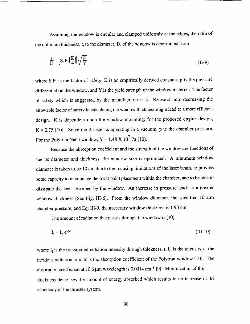
Assumingthewindow is circularandclampeduniformly at theedges,theratio of
theoptimumthickness,t, to thediameter,D, of thewindowis determinedfrom
(III-9)
whereS.F.is the factorof safety,K is anempiricallyderivedconstant,p is thepressure
differentialon thewindow,andY is theyield strengthof thewindow material. Thefactor
of safetywhich is suggestedby the manufactureris 4. Researchinto decreasingthe
allowablefactorof safetyin calculatingthewindowthicknessmight leadto a moreefficient
design. K is dependentupon the window mounting; for the proposedenginedesign,
K = 0.75 [10]. Sincethe thruster is operatingin a vacuum,p is the chamberpressure.
For thePolytranNaC1window,Y = 1.48X 10⁷Pa[10].
Becausetheabsorptioncoefficientandthestrengthof thewindow arefunctionsof
the its diameterand thickness,the window size is optimized. A minimum window
diameteris takento be 10cmdueto thefocusinglimitationsof the laserbeam,to provide
somecapacityto manipulatethefocalpointplacementwithin thechamber,andtobeableto
dissipatethe heatabsorbedby the window. An increasein pressureleadsto a greater
window thickness(SeeFig. III-6). From the window diameter,the specified 10 atm
chamberpressure,andEq. III-9, thenecessarywindow thicknessis 1.93cm.
Theamountof radiationthatpassesthroughthewindowis [10]
It = Iee-at (III-10)
whereI t is thetransmittedradiationintensitythroughthickness,t, Io is theintensityof the
incident radiation,ando_is theabsorptioncoefficientof the Polytranwindow [10]. The
absorptioncoefficientat 10.6p.mwavelengthis 0.0014cm-1[9]. Minimizationof the
thicknessdecreasesthe amountof energyabsorbedwhich resultsin an increasein the
efficiencyof thethrustersystem.
98
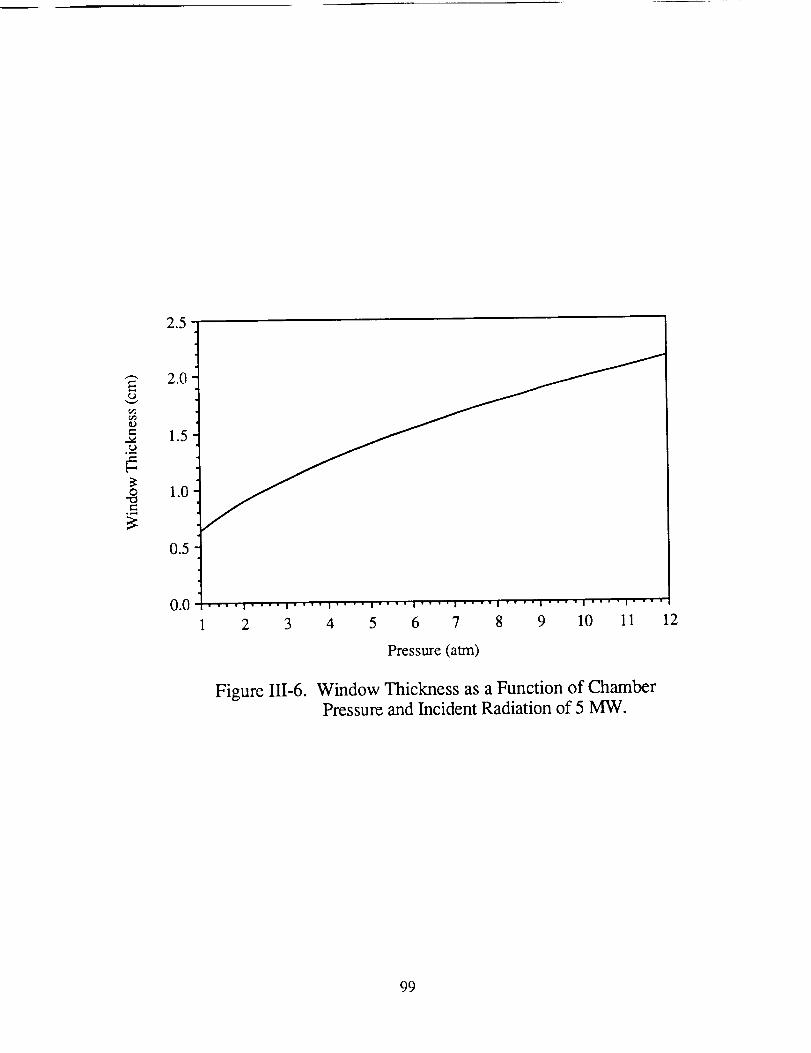
2.5
_" 2.0
tt_
e-1.5
° _,,,q
_ 1.o
0.5
0.0
1 2 3
Figure III-6.
4 5 6 7 8 9 10 11
Pressure (atm)
Window Thickness as a Function of ChamberPressure and Incident Radiation of 5 MW.
12
99
Theamountof energyabsorbedby thewindow, Iab,is thedifferencebetweenthe
intensityof theincidentradiation,Io,andthetransmittedradiation:
Iab= Io{1-e-at) (III-11)
Theamountof energyabsorbedasafunction of chamberpressureis plottedin Fig. 1II-7
for laserpower levelsof 4, 5, and6 MW. Thepower absorbedincreaseswith chamber
pressuredueto theconcomitantincreasein thewindowthickness.For thechosenchamber
pressureof 10atm and Io = 5.4 MW, 14.8kW of power is absorbedby the window.
Theenergythatis not radiatedfrom thewindow needsto bedissipatedby activecooling.
It is suggestedby Eskridge,et al. [6] that film cooling of the window is anappropriate
methodof heatdissipation.
THEORETICAL LASER ENERGY ABSORPTION
Hydrogen Plasma Formation
The initial plasma formation was a major concern of early researchers on the subject
of laser propulsion [5]. This concern is attributed to the low absorptivity of hydrogen at
low temperatures. To ignite the hydrogen plasma in the absorption chamber, a source of
free electrons must be present to absorb the laser light and heat the hydrogen to plasma
temperatures. Once the hydrogen forms a plasma, nearly 100% of the incoming laser
energy is absorbed in the plasma.
There are three methods of obtaining a source of free electrons for laser energy
absorption. These methods include ignition of the hydrogen plasma by laser bombardment
of seedants, by the use of electrical discharges, and by pulsing an additional laser.
Using seedants is the most complex of the ignition systems and contains more
performance penalties than the pulsed laser concept. A seedant is most likely to be added to
the hydrogen flow for only a short period of time. The seedant thus needs its own storage
and mixing systems, which requires further research. Many of the seedants such as H20
100
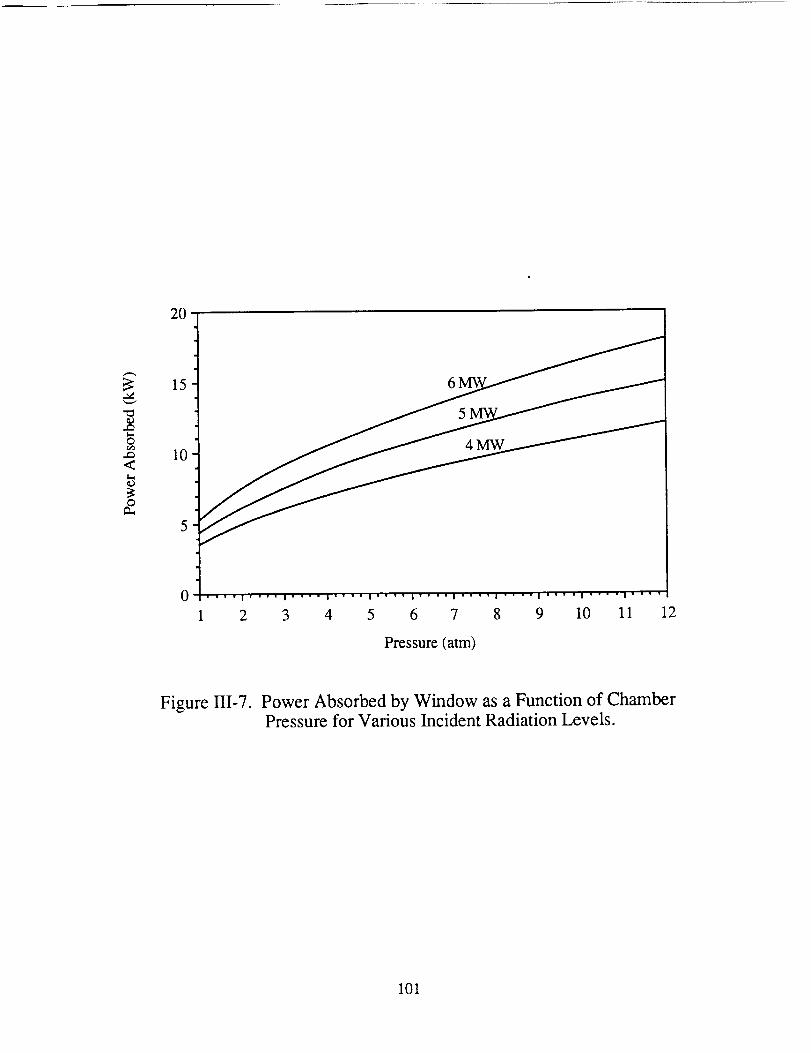
20
3:
t_
O
..Q
<
ID
_2
15
10
5
0
6 5
.... I ' " '' I ' "'" I '" " ' I .... l" " "" I " " " ' I .... I .... I .... I ....
2 3 4 5 6 7 8 9 10 11 12
Pressure (atm)
Figure III-7. Power Absorbed by Window as a Function of ChamberPressure for Various Incident Radiation Levels.
101
or A1203containoxygen[11]. As aresult,usingseedantscausesoxidationwhich erodes
theinnerchamberwalls andnozzle. Besidestheengineeringcomplicationsthat seedants
incur, seedantsin theexhaustinterferewith theincomingtransmittedlaserbeam. For the
aforementionedreasons,it isnoteproposedto employseedantstoignite theplasma.
Electricaldischargemethods,althoughmorefavorablethantheuseof seedants,are
alsoquitecomplex.Thesemethodsrequiretheadditionof acathode/anodeelectrodepairin
theabsorptionchamber.Thesurvivalfor reuseof suchasetupis questionableandrequires
furtherinvestigation.
Thepreferredmethodfor the ignition of the hydrogenplasmais to producegas
breakdownby apulsedlaserin addition to thecontinuouslaser. Sincethelaserpulseis
obtainedby Q-switching the laser, the complexity of the onboard systemis kept to a
minimum. The pulsedlaseris alsothe "cleanest,leastintrusive,andmostreliableof the
availableoptions."[6] Furthermore,therearenoadditionalthrusterperformancepenalties
associatedwith thismethod.
In the pulsed laser ignition system,the pulse of laser energyproducesa gas
breakdownwithin thepropellant.Whenthisoccurs,asmallregionof highelectrondensity
(i.e.aplasmacore)is formed. A detailedexplanationof theexactmethodof pulsedplasma
ignition is discussedby Eskridge, et al., [6] and Moody [12]. The results of their
experimentalworkshowthatthepulsingof a 30kW laserfor 150nanosecondsis enough
to sparkaplasmaat thefocalpoint in hydrogengas.The laserusedfor their experiments
wasaCO2laserof thesamewavelengthasin theproposedlasersystem.
Sincetheproposedsystemis to operatewith hydrogenat 10atm,a pressurehigher
thanwhathasbeentested,it is necessaryto discusstheeffectsof this higherpressureon
thebreakdownintensity, i.e., easeof plasmaignition. In general,absorptivity increases
linearly with increasingpressure. Thus the breakdownintensity, which is inversely
proportionalto absorptivity,decreasesasthe pressureincreases[13]. In supportof this
theoretical relationship, experimentaldata confirms that the breakdownintensity of
102
hydrogengasdecreaseswith increasingpressure(SeeFig. 111-8).The assumptionis
thereforemadethatthebreakdownintensityof hydrogenis lower for apressureof 10atm
thanthatof 5 atmin thestudiesconductedbyEskridge,et.al. [6].
Steady State Hydrogen Plasma
In the steady-statecase,a sustainedhydrogenplasmaresidesin the absorption
chamberandabsorbsnearly 100%of the incoming laserenergy[6]. Experimentaldata
from Eskridge,et al. [6] showsthat, asthe intensity of the laserincreases,theradiation
which is notabsorbedby theplasmadecreasesrapidly (SeeFig. Ili-9).
Experimentalresults for steady-statehydrogenplasmasare limited, but gases
similar to hydrogen,suchasargon,proveto be successfulin forming sustainedplasmas.
Experimentaldata for the plasmastestedconfirms the mathematicalmodeling of the
temperatureandpressuregradients[6].
The absorptionof the energywithin the plasmaregion is attributed mainly to
inverseBremsstrahlungabsorption.This typeof absorptionisexplainedasfollows:
Absorptionoccurswhenaphotonis absorbedby a freeelectronduring a
collision with either a neutral atom or an ion. The excited electron
eventuallytransfersits energyto the surroundinggasthroughcollisions,
raisingthebulk temperatureof thegas[5].
Becauseof the high temperatureswithin theplasma,thehydrogenbecomessufficiently
ionizedto produceanabundanceof freeelectrons.This sourceof electronsis responsible
for thesuccessfulabsorptionof laserenergyby theinverseBremsstrahlungprocess.
103
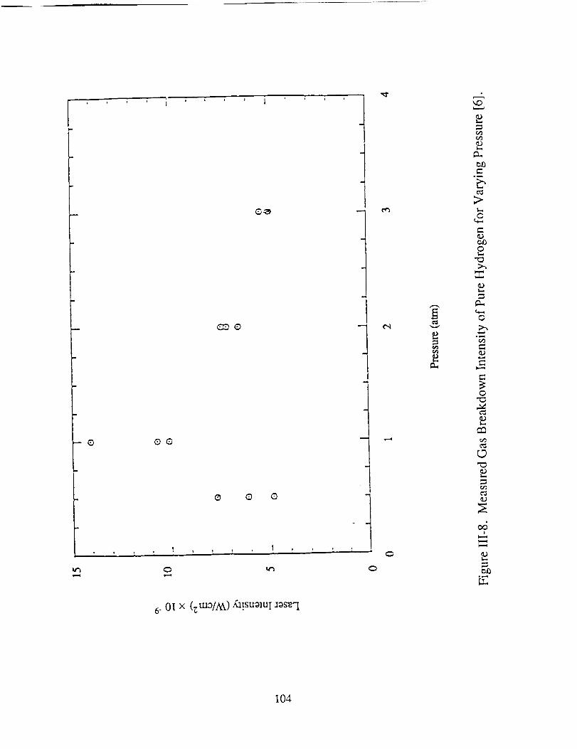
O
q
QO
G G
, , I .... I ,
6- 0T x (_m0/Ak)/a!sugluI _gs_l
J
!
r_
¢q v
b
t..,O
G
_D
O
09
O
_D
D
o_
104
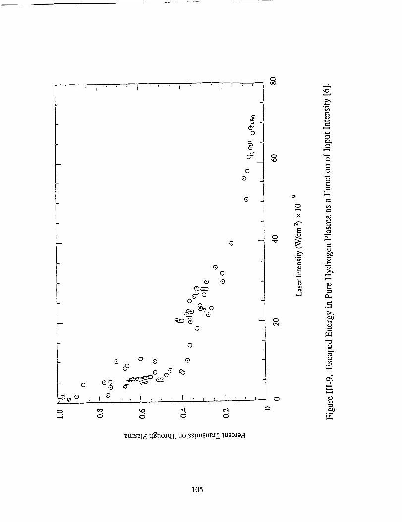
' I I ' _ ' I
#O
P
O
O
G
G
G
O
Q O
(9
G
G Q O O
C
•oeo i o
.4 c_ c_ c5 oC_
_tuse[d q_noaq,L uo!ss_stre.II.lu0_0d
0O0
o
o
X
E
v
L_
o
0
,.A
;>_
o
o
o
r,#'2
E
0t_
°_,,q
_A
r,,¢2
ca0
105
Plasma Stability
The plasma is initially formed at the focal point of the incoming laser beam. In the
steady state, the plasma tends to propagate up the laser beam until the intensity of the beam
becomes too small to sustain the plasma. At this point, the plasma extinguishes; however,
there are methods that force the plasma to translate back to the focal point. One method of
controlling the plasma propagation is manipulation of the propellant characteristics in the
absorption chamber. The velocity of the propellant counterflow in the chamber can be
increased to "hold" the plasma downstream of the incoming beam (See Fig. III-2). The
pressure in the absorption chamber may also be manipulated to "hold" the plasma in a
smaller region around the focal point of the laser beam. Further experimental research of
hydrogen plasmas must be performed to determine whether the proposed flow parameters
result in an inherently stable plasma.
106
LASER AND ASSOCIATED OPTICAL SYSTEM
Anna CinnigerAmy Prochko
Jeff SlostadTerri Schmitt
The spacecraft thrusters receive energy from two solar pumped lasers in sun-
synchronous orbit around the earth (See Fig. III-10). Solar pumping is achieved by
concentrating solar energy into blackbody cavitities which serve to excite the lasing medium
in tubes lining the blackbody cavity [14]. The output beam of each laser is transmitted and
directed by a system of mirrors and laser relay units to one of two inflatable receivers on
the spacecraft. Optical trains direct the beamed energy from each receiver to its respective
thruster window.
SOLAR COLLECTOR
A 15% efficiency is projected for solar to laser power conversion [14]. Given a
solar flux of 1.3 kW/m 2 at Low Earth Orbit, a solar collector area of 5,155 m 2 is required
for each megawatt of laser output. In the proposed design, each laser has six solar
collectors. Figure III-11 illustrates the circular arrangement of the collectors, which are
positioned opposite the sun from the six blackbody cavities of the laser. The collectors
concentrate the solar flux directly into the blackbody cavities. Frontal and side views of the
solar concentration system are also shown in Fig. III-11. The reflective surface of the
collectors is fabricated of aluminized Kapton to provide high reflectivity over a broad band
of wavelengths. The total mass of the collectors for each laser is estimated to be
31,000 kg [15,4].
LASER
To meet the propulsion requirement of 5.4 MW at each thruster window, each laser
must generate approximately 6 MW to compensate for the losses at the reflecting surfaces
and the losses due to diffraction. Losses at each of the reflective surfaces are on the order
107
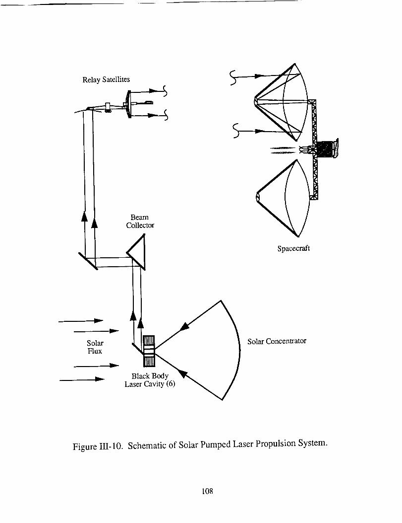
RelaySatellites
k _ BeamCollector
/
SolarFlux
...._ Blac- Laser Cavity (6) _ /¢
-,..,/
Spacecraft
Solar Concentrator
Figure III-10. Schematic of Solar Pumped Laser Propulsion System.
108
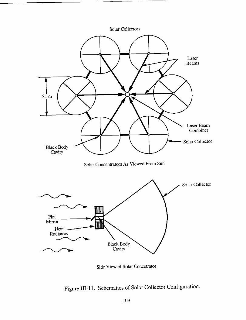
SolarCollectors
LaserBeams
81m
LaserBeamCombiner
BlackBodyCavity
SolarCollector
SolarConcentratorsAs ViewedFromSun
Flat .._
Mirror -__Heat _ Illl_\
Radiators \
'ac /B kBo
Cavity
Solar Collector
Side View of Solar Concetrator
Figure III-11. Schematics of Solar Collector Configuration.
109
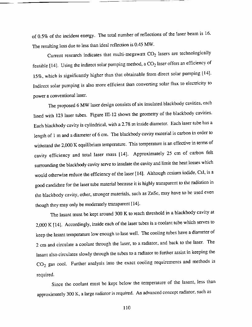
of 0.5% of the incident energy. The total number of reflections of the laser beam is 16.
The resulting loss due to less than ideal reflection is 0.45 MW.
Current research indicates that multi-megawatt CO 2 lasers are technologically
feasible [14]. Using the indirect solar pumping method, a CO 2 laser offers an efficiency of
15%, which is significantly higher than that obtainable from direct solar pumping [14].
Indirect solar pumping is also more efficient than converting solar flux to electricity to
power a conventional laser.
The proposed 6 MW laser design consists of six insulated blackbody cavities, each
lined with 123 laser tubes. Figure III-12 shows the geometry of the blackbody cavities.
Each blackbody cavity is cylindrical, with a 2.78 m inside diameter. Each laser tube has a
length of 1 m and a diameter of 6 cm. The blackbody cavity material is carbon in order to
withstand the 2,000 K equilibrium temperature. This temperature is an effective in terms of
cavity efficiency and total laser mass [14]. Approximately 25 cm of carbon felt
surrounding the blackbody cavity serve to insulate the cavity and limit the heat losses which
would otherwise reduce the efficiency of the laser [14]. Although cesium iodide, CsI, is a
good candidate for the laser tube material because it is highly transparent to the radiation in
the blackbody cavity, other, stronger materials, such as ZnSe, may have to be used even
though they may only be moderately transparent [ 14].
The lasant must be kept around 300 K to reach threshold in a blackbody cavity at
2,000 K [14]. Accordingly, inside each of the laser tubes is a coolant tube which serves to
keep the lasant temperature low enough to lase well. The cooling tubes have a diameter of
2 cm and circulate a coolant through the laser, to a radiator, and back to the laser. The
lasant also circulates slowly through the tubes to a radiator to further assist in keeping the
CO 2 gas cool. Further analysis into the exact cooling requirements and methods is
required.
Since the coolant must be kept below the temperature of the lasant, less than
approximately 300 K, a large radiator is required. An advanced concept radiator, such as
110
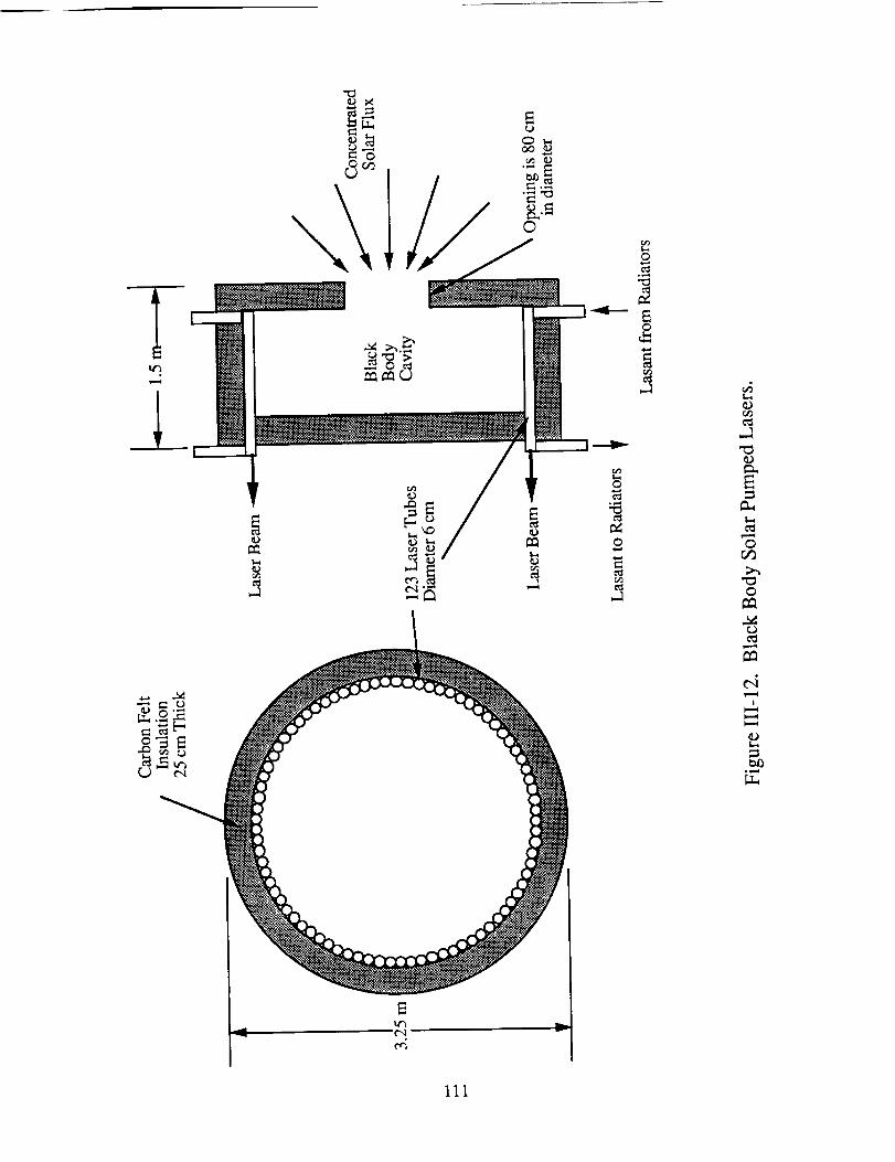
,l
©
o
.1
oor]
o
111
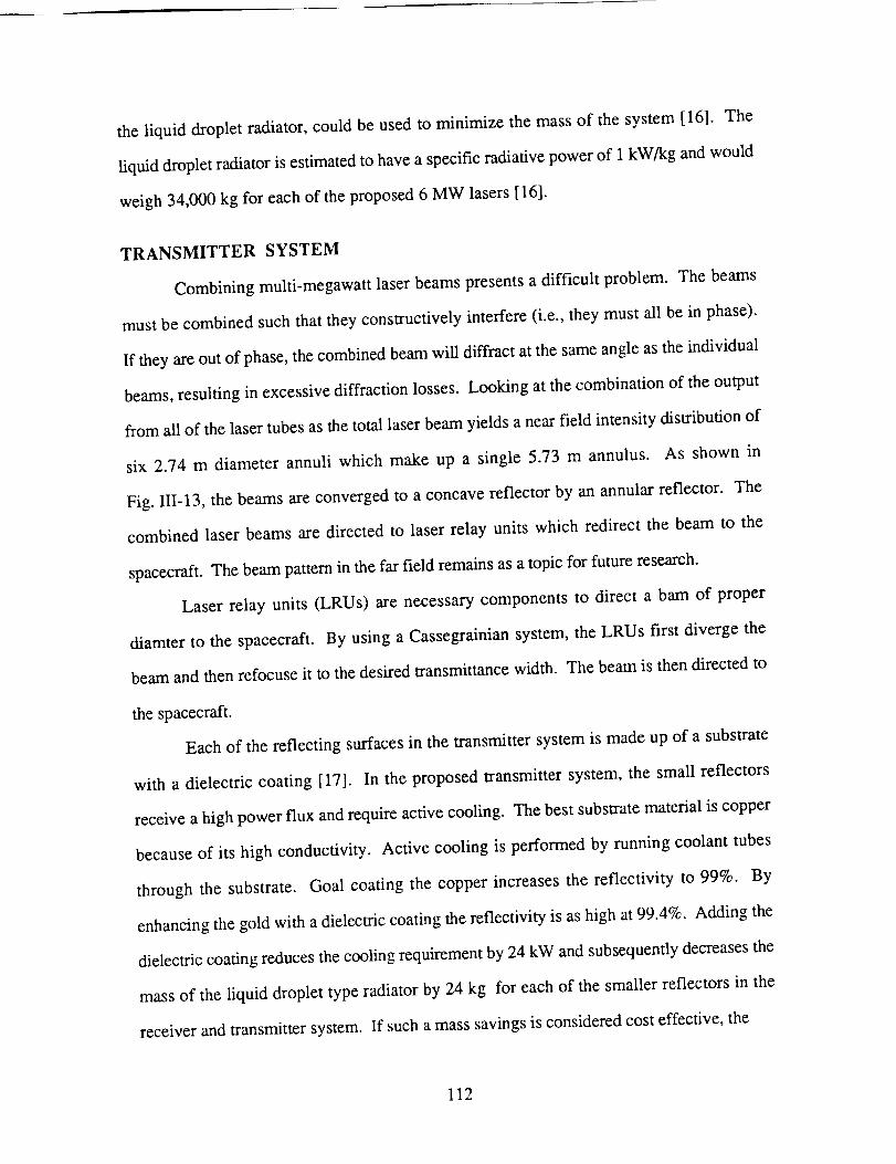
the liquid droplet radiator, could be used to minimize the mass of the system [16]. The
liquid droplet radiator is estimated to have a specific radiative power of 1 kW/kg and would
weigh 34,000 kg for each of the proposed 6 MW lasers [16].
TRANSMITTER SYSTEM
Combining multi-megawatt laser beams presents a difficult problem. The beams
must be combined such that they constructively interfere (i.e., they must all be in phase).
If they are out of phase, the combined beam will diffract at the same angle as the individual
beams, resulting in excessive diffraction losses. Looking at the combination of the output
from all of the laser tubes as the total laser beam yields a near field intensity distribution of
six 2.74 m diameter annuli which make up a single 5.73 m annulus. As shown in
Fig. Ili-13, the beams are converged to a concave reflector by an annular reflector. The
combined laser beams are directed to laser relay units which redirect the beam to the
spacecraft. The beam pattern in the far field remains as a topic for futttre research.
Laser relay units (LRUs) are necessary components to direct a bam of proper
diamter to the spacecraft. By using a Cassegrainian system, the LRUs first diverge the
beam and then refocuse it to the desired transmittance width. The beam is then directed to
the spacecraft.
Each of the reflecting surfaces in the transmitter system is made up of a substrate
with a dielectric coating [17]. In the proposed transmitter system, the small reflectors
receive a high power flux and require active cooling. The best substrate material is copper
because of its high conductivity. Active cooling is performed by running coolant tubes
through the substrate. Goal coating the copper increases the reflectivity to 99%. By
enhancing the gold with a dielectric coating the reflectivity is as high at 99.4%. Adding the
dielectric coating reduces the cooling requirement by 24 kW and subsequently decreases the
mass of the liquid droplet type radiator by 24 kg for each of the smaller reflectors in the
receiver and transmitter system. If such a mass savings is considered cost effective, the
112
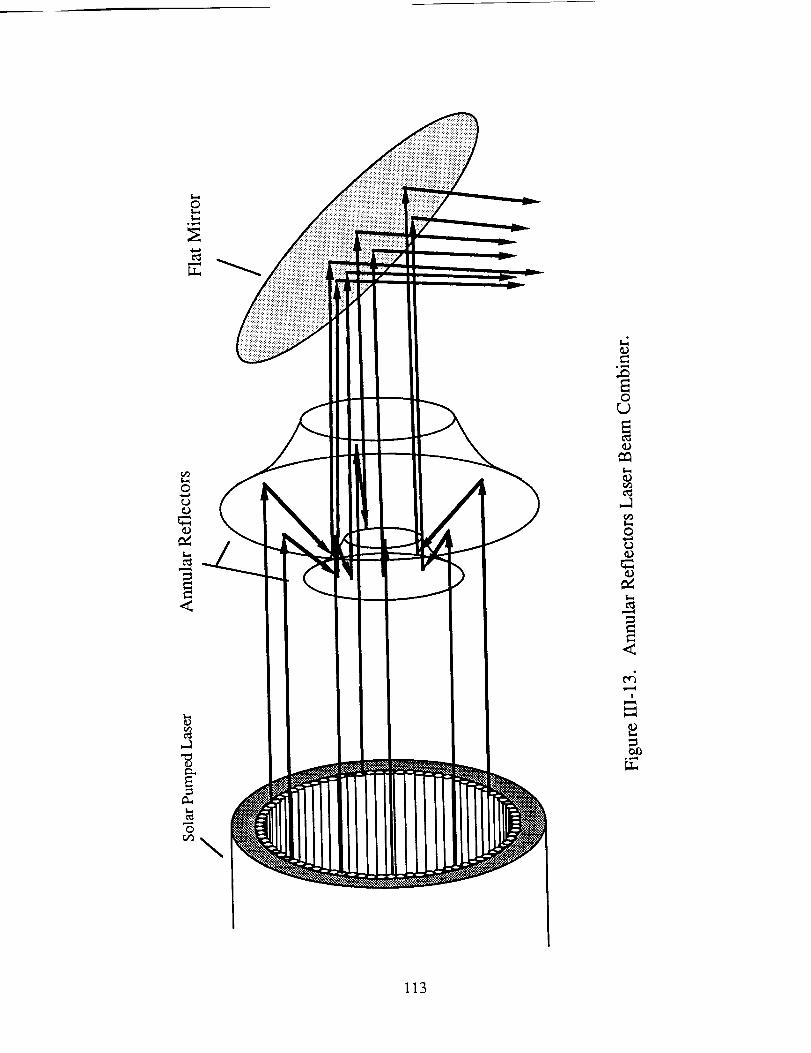
©
0r..)
113
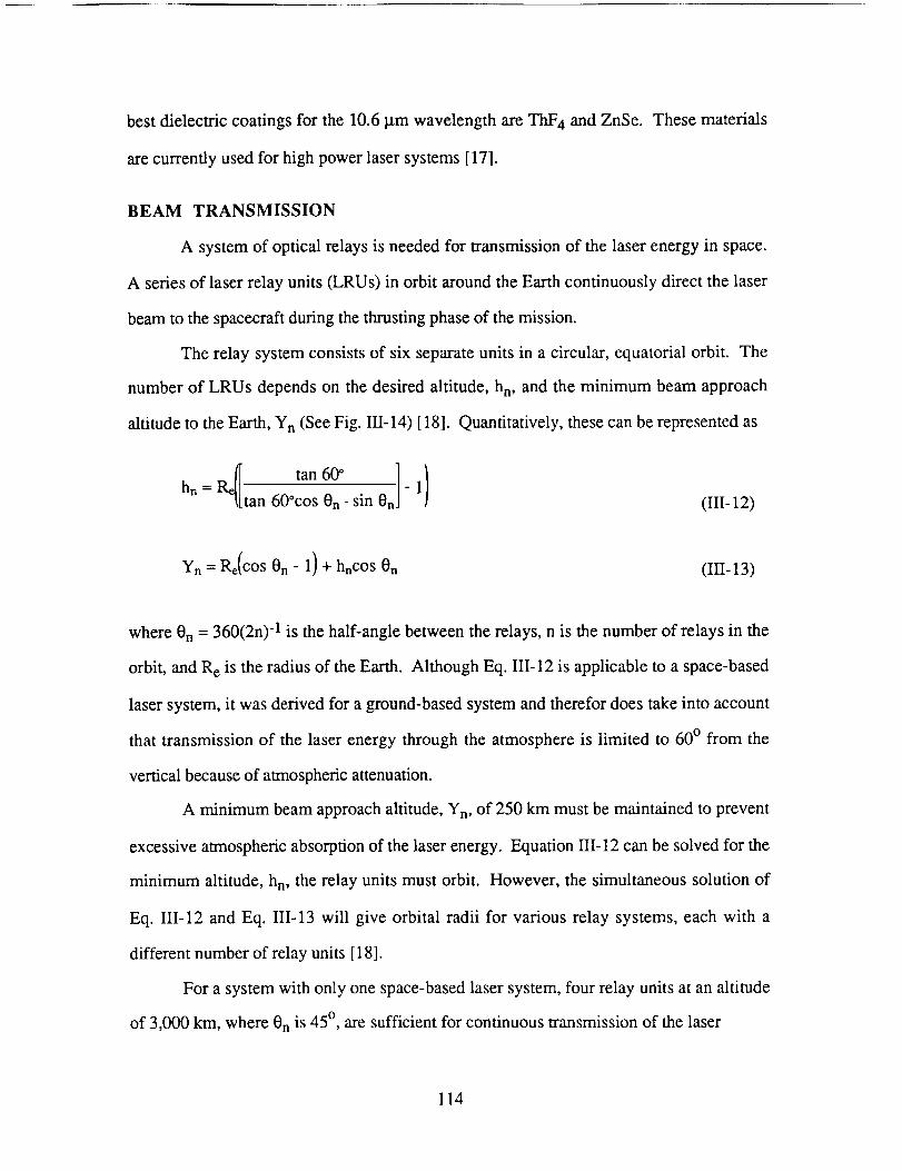
best dielectric coatings for the 10.6 I.tm wavelength are ThF 4 and ZnSe. These materials
are currently used for high power laser systems [17].
BEAM TRANSMISSION
A system of optical relays is needed for transmission of the laser energy in space.
A series of laser relay units (LRUs) in orbit around the Earth continuously direct the laser
beam to the spacecraft during the thrusting phase of the mission.
The relay system consists of six separate units in a circular, equatorial orbit. The
number of LRUs depends on the desired altitude, h n, and the minimum beam approach
altitude to the Earth, Yn (See Fig. III-14) [18]. Quantitatively, these can be represented as
R_ tan60° -] )hn = - 1tan 60°cos On- sin On (111-12)
Yn= 1%(cos0n- 1) + hncos 0n (111-13)
where On = 360(2n) "1 is the half-angle between the relays, n is the number of relays in the
orbit, and R e is the radius of the Earth. Although Eq. III-12 is applicable to a space-based
laser system, it was derived for a ground-based system and therefor does take into account
that transmission of the laser energy through the atmosphere is limited to 600 from the
vertical because of atmospheric attenuation.
A minimum beam approach altitude, Yn, of 250 km must be maintained to prevent
excessive atmospheric absorption of the laser energy. Equation 111-12 can be solved for the
minimum altitude, h n, the relay units must orbit. However, the simultaneous solution of
Eq. 111-12 and Eq. II1-13 will give orbital radii for various relay systems, each with a
different number of relay units [18].
For a system with only one space-based laser system, four relay units at an altitude
of 3,000 km, where On is 45 °, are sufficient for continuous transmission of the laser
114
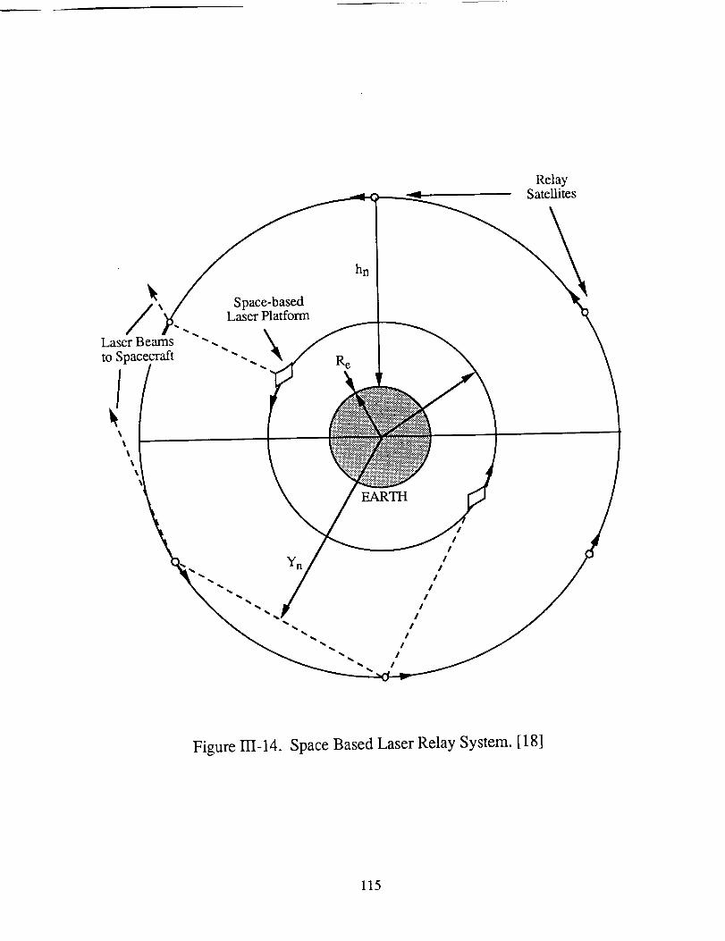
RelaySatellites
/Laser Beams
to Spacecraft
Space-bas_Laser Plat_rm
hn
EARTH
Yn
II
II
I
II
II
II
II
I
Figure 111-14. Space Based Laser Relay System. [18]
115
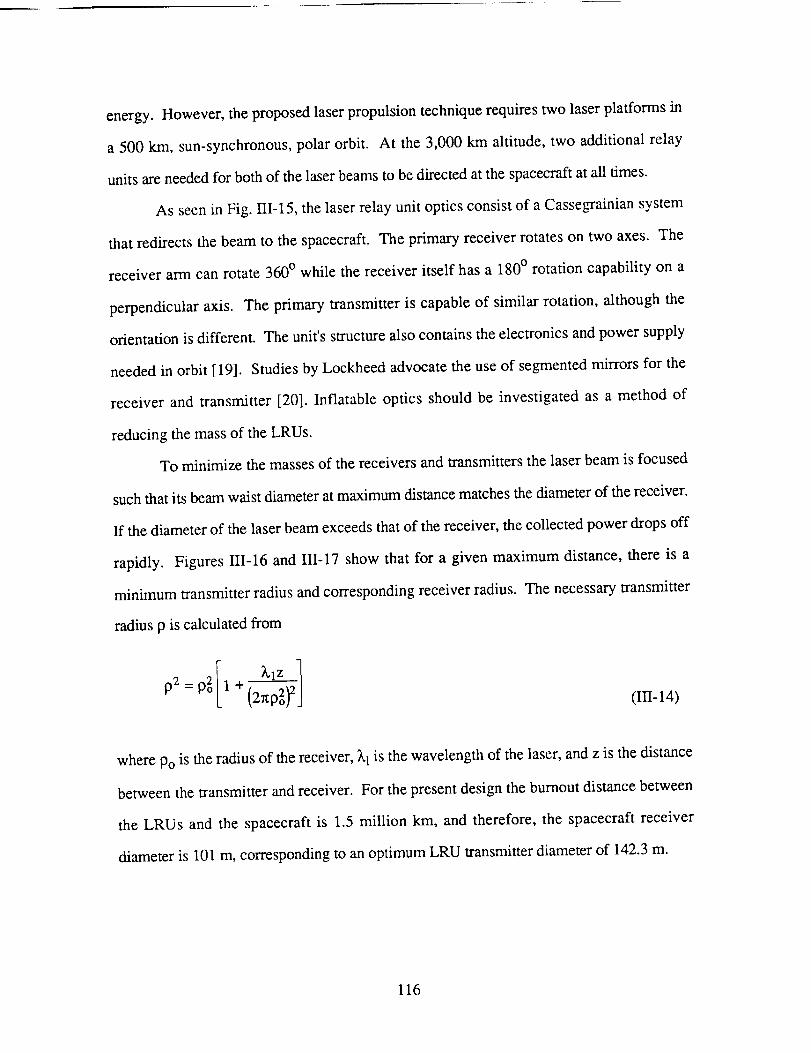
energy. However,theproposedlaserpropulsiontechniquerequirestwo laserplatformsin
a 500 km, sun-synchronous,polar orbit. At the 3,000km altitude, two additionalrelay
unitsareneededfor bothof thelaserbeamsto bedirectedatthespacecraftat all times.
As seen in Fig. 111-15, the laser relay unit optics consist of a Cassegrainian system
that redirects the beam to the spacecraft. The primary receiver rotates on two axes. The
receiver arm can rotate 360 ° while the receiver itself has a 180 ° rotation capability on a
perpendicular axis. The primary transmitter is capable of similar rotation, although the
orientation is different. The unit's structure also contains the electronics and power supply
needed in orbit [19]. Studies by Lockheed advocate the use of segmented mirrors for the
receiver and transmitter [20]. Inflatable optics should be investigated as a method of
reducing the mass of the LRUs.
To minimize the masses of the receivers and transmitters the laser beam is focused
such that its beam waist diameter at maximum distance matches the diameter of the receiver.
ff the diameter of the laser beam exceeds that of the receiver, the collected power drops off
rapidly. Figures 111-16 and III-17 show that for a given maximum distance, there is a
minimum transmitter radius and corresponding receiver radius. The necessary transmitter
radius p is calculated from
(III-14)
where Po is the radius of the receiver, _.1 is the wavelength of the laser, and z is the distance
between the transmitter and receiver. For the present design the bumout distance between
the LRUs and the spacecraft is 1.5 million km, and therefore, the spacecraft receiver
diameter is 101 m, corresponding to an optimum LRU transmitter diameter of 142.3 m.
116
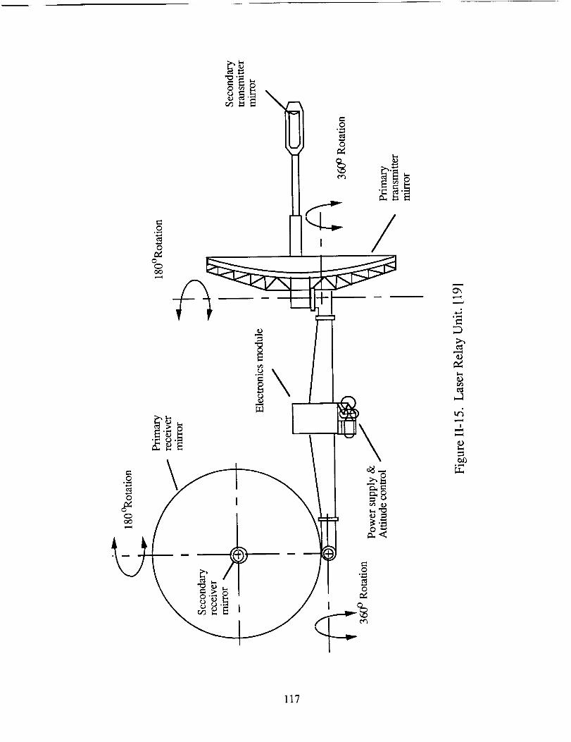
\
/
• i,,,,,i
e_
117
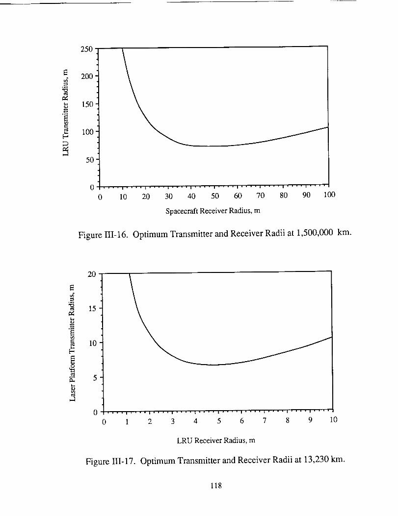
E
°..-t
° i,..-i
E=
#
250
200
150
100
5O
0 .... I .... I " " " " I .... I .... I .... I " " " " I " " " " I .... I v " " "
10 20 30 40 50 60 70 80 90 100
Spacecraft Receiver Radius, m
Figure III-16. Optimum Transmitter and Receiver Radii at 1,500,000 km.
20
_g° w...i
°_..4
t_
15
10
5
0 WW|II|n||I|'|IIIInII|||WlIIIIIIIWlIWWWlIIII|I|JI!
0 1 2 3 4 5 6 7 8 9 10
LRU Receiver Radius, m
Figure ]]I-17. Optimum Transmitter and Receiver Radii at 13,230 km.
118
ThemaximumdistancebetweenthelaserplatformandaLRU is 13,200km. Figure111-16
showsthatthebestcombinationof laserplatformtransmitterandLRU receiverdiametersis
13.3m and9 m, respectively.
TRACKING AND POINTING
The ability of the tracking and aiming system to hit its target is a major concern of
any beamed energy system. Most research in this area is done by the Department of
Defense for application towards the Strategic Defense Initiative. Consequently, most
information regarding even peaceful uses of tracking and aiming systems, such as a laser
powered spacecraft, is classified and unavailable for use in this report.
The tracking problem includes knowledge of the exact location of the spacecraft, the
laser platform, and the laser relay units. The location of the laser platform and laser relay
units can be determined though a variety of methods. The TOPEX program, for example,
utilizes laser ranging using cube comer reflectors and various Doppler ranging techniques.
The most accurate Doppler ranging technique uses the NAVSTAR satellites. For space
systems using the NAVSTAR system, location accuracies up to 2 - 3 cm can be
achieved [21].
Accurate aiming of the laser necessitates knowledge of the real time locations, in
other words, the instantaneous positions, of the laser platform, laser relay units, and the
spacecraft. Unfortunately, the accuracy of the laser and Doppler ranging techniques is
greatly reduced for systems demanding real time information instead of the Doppler
history. Even with onboard data analysis, which avoids the time delay incurred by ground
processing, the best accuracy that can be attained instantaneously is approximately 15 m.
Using Doppler ranging from earth to locate the spacecraft would not be feasible due
to the feedback time of the system. The signal travel time to the ship, and then back to the
laser platform would take several seconds.
119
Thelocationof thespacecraftcouldmosteasilyandaccuratelybedeterminedusing
astarscanner.A starscannersystemusesanonboardcomputerto comparethelocationof
the sunandstarsfrom video inputsto an internal starcataloguestoredin the computer.
Theerrorof theincomingbeamscouldthenbetransmittedto thelaserplatform,andbeam
adjustmentscouldthenbemadefor aimingthelaser.
The aiming or pointing of the laseris a control problem, relying on powerful
computerslocatedon each componentin the laser system. Advancements in system
modeling and computerized artificial intelligence will determine whether a closed or open
loop control system is used. Several inherent difficulties however, are associated with
aiming the laser beam.
One major difficulty of the laser propulsion system is the mechanical aiming of the
beam over the large distances required. An initial aiming error of five microradians results
in a beam displacement of approximately 10 m at a distance of 2 million km. The most
accurate aiming that could be hoped for in the near future is on the order of 500
nanoradians [22]. An analysis of this substantial error when compared to the unavoidable
beam spreading by diffraction shows the beam spreading to be 5 times smaller than the
aiming error.
Errors in an orbiting system are further increased by outside influences on the laser
system, including thermal shocks due to day-night cycling, aerodynamic drag force, which
is greatly influenced by sun-spot activity, and gravity gradients induced by variations of the
Earth's surface height.
These smaller disturbances can be eliminated by placing the system at a libration
point, where the Earth's and the Moon's gravity fields will cancel. Placing the laser system
in operation at a libration point however, is more expensive than placing the system in a
low Earth orbit. Serviceability of the system also becomes increasingly more difficult and
expensive when considering anything but a low Earth orbit.
120
Consideringall of these factors leads to the conclusion that, without substantial
advances in tracking technology, this system will not be possible within the foreseeable
future. At this time, only by greatly decreasing the burnout distance of the ship by adding
more thrusters, or using a more powerful laser beam, could the problems of tracking and
aiming be overcome. However, as stated previously, the DOD is sponsoring a
considerable amount of research in this area, and many answers may already exist.
121
SPACECRAFT RECEIVER
Anna CinnigerAmy Prochko
SYSTEM
One of the primary constraints on the choice of a receiver onboard the spacecraft is
its mass. Three generic types of receivers are considered for this mission. Table III-1
shows the estimated masses for adaptive, rigidized, and inflatable optics; inflatable optics
are the most attractive choice. The adaptive optics have the highest possible concentration
ratio, but the lower concentration ratios attainable with rigidized and inflatable optics are
sufficient to supply the engine with the required laser power [15]. Although the estimated
mass of rigidized optics is not completely unreasonable, inflatable optics are the better
choice because they are less massive and have been shown to retain a more ideal surface
shape [15]. The inflatable optics also allows a micro-meteoroid to pass through the balloon
with little damage to the optical performance.
The inflatable optics consist of a balloon supported by a rigidized torus and
aluminum wires inset in the reflecting material. The inflation gas, reflecting surface, and
the balloon must be lightweight and non-absorbing to infrared radiation. Furthermore, the
balloon material must be flexible and resistant to separation. The back surface of the
balloon is aluminized for reflection. Upon inflation, the wires that support the collector
become stressed beyond their yield point and maintain the desired surface shape even when
the collector is deflated. An internal gas pressure of 10 -5 atm is sufficient to generate the
required parabolic shape [15]. With the addition of piping and refill gas, the total mass of
each receiver is approximately 8,100 kg.
122
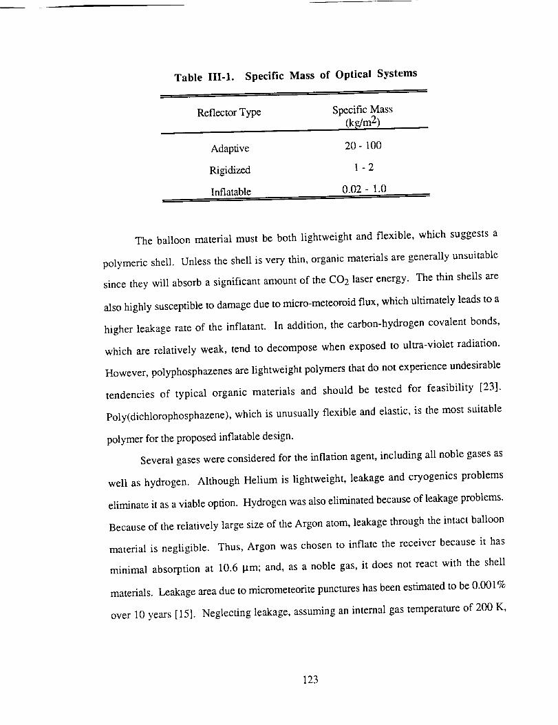
Table III-1. Specific Mass of Optical Systems
Reflector Type Specific Mass
(k_m 2)
Adaptive 20- 100
Rigidized 1 - 2
Inflatable 0.02- 1.0
The balloon material must be both lightweight and flexible, which suggests a
polymeric shell. Unless the shell is very thin, organic materials are generally unsuitable
since they will absorb a significant amount of the CO2 laser energy. The thin shells are
also highly susceptible to damage due to micro-meteoroid flux, which ultimately leads to a
higher leakage rate of the inflatant. In addition, the carbon-hydrogen covalent bonds,
which are relatively weak, tend to decompose when exposed to ultra-violet radiation.
However, polyphosphazenes are lightweight polymers that do not experience undesirable
tendencies of typical organic materials and should be tested for feasibility [23].
Poly(dichlorophosphazene), which is unusually flexible and elastic, is the most suitable
polymer for the proposed inflatable design.
Several gases were considered for the inflation agent, including all noble gases as
well as hydrogen. Although Helium is lightweight, leakage and cryogenics problems
eliminate it as a viable option. Hydrogen was also eliminated because of leakage problems.
Because of the relatively large size of the Argon atom, leakage through the intact balloon
material is negligible. Thus, Argon was chosen to inflate the receiver because it has
minimal absorption at 10.6 _tm; and, as a noble gas, it does not react with the shell
materials. Leakage area due to micrometeorite punctures has been estimated to be 0.001%
over 10 years [15]. Neglecting leakage, assuming an internal gas temperature of 200 K,
123
andassuminga sphericalballoonwith a 50.5m radius,approximately14kg of Argon is
needed to inflate the balloon.
The reflective coating suggested for the reflective side of the balloon is dielectric
coated aluminum [15]. The maximum flux at the receiver is less than 0.5 kW/m 2, which is
small enough that active cooling of the receiver is unnecessary.
OPTICAL TRAIN TO THRUSTER WINDOW
The function of the optical train is to direct the beam from the receiver to the thruster
window. Figure III-18 illustrates how the Cassegrainian receiver passes the laser beam to
the optical train within the receiver support structure. The receiver is able to rotate 360 °
around the support structure. The mirrors of the optical train are driven by motors to adjust
to every movement made by the receiver and continuously deliver the beam to the thruster
window. The directing mirror, at the top of the structure, moves with the receiver in order
to keep the beam directed down through the center of the structure. At the bottom, the
second directing mirror rotates with the engine as it moves around the support structure.
This mirror also focuses the beam into the thruster chamber to the necessary spot size to
sustain a plasma breakdown within the hydrogen propellant.
124
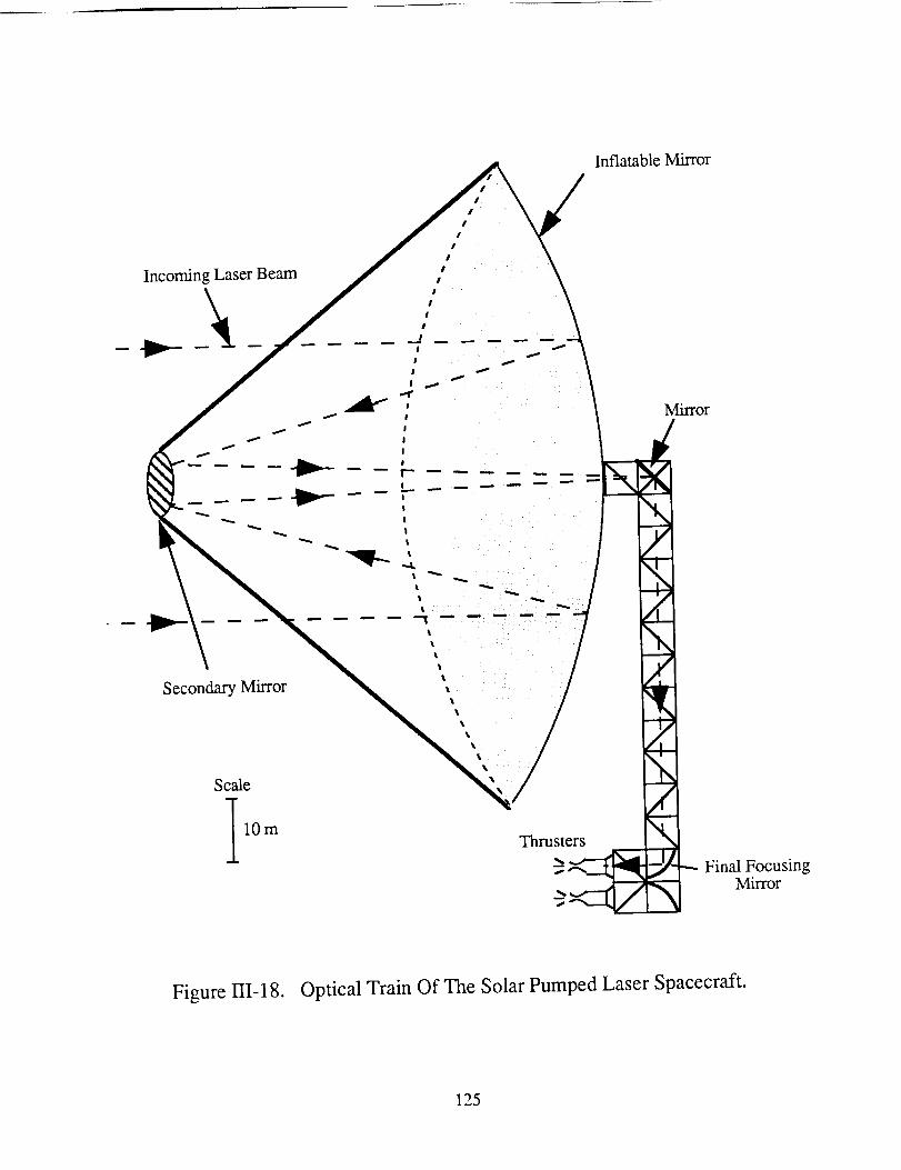
Inflatable Mirror
Final FocusingMirror
Figure 111-18. Optical Train Of The Solar Pumped Laser Spacecraft.
125
SPACECRAFT DESIGN
Joseph Burianek
When considering the design of the structure for the spacecraft there are many
parameters to consider. As with all space structures, it is important to keep both the mass
and the cost as low as possible. This spacecraft also has the added design problem that it
has to be stiff enough that the laser radiation that is received by the collectors proceeds to
the thruster without deviation or loss of optical quality. The structures of the spacecraft
also need to be protected from both the atmosphere and any thermal radiation from the sun.
In order to obtain a workable design for the spacecraft all of these considerations
were taken into account. As seen in Fig. 111-19 the spacecraft consists of four main parts:
the payload and aerobrake, the propellant tanks and its surrounding structures, the thruster,
with the collectors and their surrounding structure.
The payload and aerobrake are placed on the front of the spacecraft for easy
jettisoning. The propellant tanks are clustered in a 20x20x25 m box (made up of individual
5 m boxes) that can accommodate up to 64 tanks (192,000 kg of propellant). Each tank is
4.2 m in diameter and will be carried to LEO on the space shuttle as half shells. The shells
will be assembled in space and placed inside individual 5 m boxes. This spacecraft will use
39 tanks, or 117,000 kg of propellant. The propulsion units are placed in such a way that
thrust is provided through the center of mass of the spacecraft. Finally, each collector is
located at the end of a 100 m truss, which is able to rotate.
TRUSS ELEMENTS
The main truss elements of the proposed design are 5 m hollow rod elements that
have an outer diameter of 4.11 cm, and a wall thickness of 2.2 mm. Each element is
fabricated of graphite/epoxy (Gr/Ep) with a coating of anodized Aluminum on the inner and
126
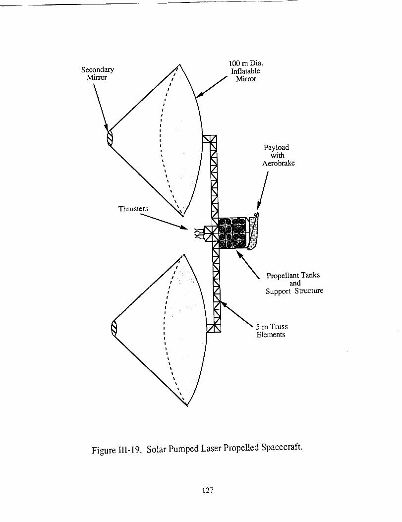
Sec°ndarYMirror
Thrust_
100m Dia.InflatableMirror
Payloadwith
Aerobrake
/
Propellant Tanksand
Support Structure
5 m TrussElements
Figure HI-19. Solar Pumped Laser Propelled Spacecraft.
127
outer surfaces. Thesedimensionsand materials were chosenfor several reasons:
1)Similarity to theelementsthat will beusedin the spacestation,2) compatibility with
spaceshuttlepayloads,3) lower massthanconventionalmetals,4) higherstiffnessthan
conventionalmetals,5) lowercostthroughfewerpartsthana trussstructurewith smaller
elements,and6)compatibilityto growin threedimensionswhenneeded.
Sincethespacestationwill bebuilt primarily of 5 m elements,the trusselements
shouldbe readily available. In fact, a smaller,ten-baytrussstructurehasalreadybeen
constructedin spaceduringMission61Bof theSpaceShuttleAtlantis (Nov./Dec.1985).
Theexperimentsweredesignedto studyspaceconstructionby astronautsin extravehicular
activity (EVA). According to Heard [24], the program's principal director, the experiment
was a success and confirmed the feasibility of EVA space assembly. At that time, there
were plans to test the feasibility of the full 5 m truss structure, but that has not yet
happened.
An additional advantage of using this size element is the advantageous relationship
between the largest space shuttle cargo and the element length. The diameter of the space
shuttle cargo bay is 4.6 m. Therefore, any payloads transported in the Space Shuttle can fit
into the truss bays of this structure (e.g. the propellant tanks).
Furthermore, whenever space flight is considered, the mass of the spacecraft is
critical. Mikulas and Bush [25] show that when constructing a similar size structure with
struts of equal thickness, structures with longer truss elements have a lower overall mass.
They show that for structures of equal length, using elements with the same bar thickness,
3 m elements would have an approximately 20% greater mass than 5 m elements.
However, there is an upper limit of strut length which is determined by ease of construction
in space and ease of transportation to LEO. For the proposed design that upper limit has
been chosen to be 5 m in an effort to make the truss compatible with the space shuttle cargo
bay, and have the same size that NASA has baselined for use on the space station truss
structure.
128
It shouldbenotedthatpre-packageddeployablestructureswereconsideredwhen
decidingwhich typeof structuresto use. Deployablestructureshavea smallerassembly
time in space.However,dueto theextraspacerequiredto storethe subsystemsusedin
deployingthestructures,the individual elementsmustbeshorter. Thereducedassembly
timewasnotdeemedto makeupfor thedisadvantagesof smallerelements.
Theproposedspacecraftdesignhassomeneedssimilar to thatof thespacestation,
which further illustratestheadvantageof usingsimilar trusselements.Dueto theoptical
integrity neededto keepthelaserbeampointedin thecorrectdirection,thestructuremust
providea stable(i.e. stiff) structure.Mikulas andBushfoundthat for a 3 m trussto have
similarstiffnesscharacteristics,it wouldhaveto weightwo to threetimesasmuchasthe5
m truss[25]. Thus,using smallerelementswould causea substantialweight penaltyor
compromiseneededstiffness,whichcannotbetolerated.
Sincesimilar trusselementsto thatof thespacestationareproposed,it is practical
to usesimilarnodeattachments.Thisrequirestheuseof nodesthatincludethepossibility
of 26 strut attachments(a picture of thesestrutsappearsin the referencedpaper by
MickulasandBush). It is possibleto attachstrutsin eachof thethreeprincipaldirections
(6nodes),eachof the45° anglepossibilities(12nodes)and8 othernodallocations. This
allowsfor growthin manypossibledirections.Eachnodehasbeendesignedto beableto
attachto its correspondingstrutquickly andeasily. Themain reasonto usethesequick
attachmentjoints is to minimizeEVA time. In fact,whenpossible,thesecouldbeboltedin
placebeforeleavingearth,to furtherminimize EVA time. It shouldbenotedthat such
nodeshavebeenusedfor manyyearsin theconstructionof groundstructuresandthereis a
largedatabaseof informationrelativeto usein space.
Materials
Materialsusedfor spacestructuresneedto bevery light weight,havelow mass-to-
strengthandmass-to-stiffnessratios,andberesistanttoradiation. Severalmaterialswhich
offer theseadvantageouscharacteristicshavebeenconsidered.Thematerialsincludethe
129
broadcategoriesof graphite/epoxycomposites(Gr/Ep), metalmatrix composites,and
carbon-carboncomposites.
Of thesematerials,metalmatrixandcarbon-carboncompositesdemonstratethebest
combined stiffness and thermal resistance. However, these also have numerous
disadvantages.First of all, themetalmatrix compositeshaveapoor responseto thermal
cyclingandexperiencelargehysteresisandresidualdimensionchangesduring thiscycling.
Thereis workbeingdoneto eliminatethis throughpostfabricationof themetalmatrix,but
this is still underdevelopment[26]. Another drawback to these two types of composites is
cost. Both the metal matrix and carbon-carbon composites are expensive and the large
added cost to use them may not be worth the advantages gained. Finally, the fact that metal
matrix and carbon-carbon composites are relatively new makes them less common, less
available and less reliable. For simplicity it is better to stick with a reliable, well known
material.
Graphite/epoxy (Gr/Ep) also exhibits low mass-to-stiffness characteristics
(although not as good as some metal matrix and carbon-carbon composites). Also, the
Gr/Ep material exhibits better thermal cycling properties [27]. Because the Gr/Ep has
favorable characteristics, is relatively inexpensive, and has a history of frequent
application, it is the material chosen for the majority of the structure. In areas where
extremely high temperatures may be encountered, the metal matrix or carbon-carbon
material should be considered for use, due to their lower thermal conductivity.
Tube Coatings
Due to the fact that the spacecraft may spend much of its time in LEO and that it
requires high stiffness and stability with little or no degradation, many environmental
aspects must be considered. The main problems to be considered are atomic oxygen
exposure, thermal cycling, charged particle radiation, ultraviolet radiation, micrometeorites,
and space debris. Many of these problems may cause a degradation in the unprotected
graphite/epoxy composite. Therefore a protective coating or wrap must be employed to
130
resist this degradation.The requirementsof this coating include resistance to the above
problems, adhesion to graphite/epoxy, abrasion resistance, and coating uniformity.
In a study conducted by Dursch and Hendricks [28], four types of coatings were
considered: anodized A1 foil, sputtered Si02/A1/A1 foil, bare A1 foil and electroplated N i
with and without a SiO x coating. Coatings were applied to 2 in diameter tubes made of
P75S/934 Gr/Ep with a longitudinal tensile modulus of 45 Msi. The targeted optical values
of the coatings were set at a solar absorbance of 0.2 to 0.35 and a thermal emittance of 0.15
to 0.25. This low absorbance reduces the maximum temperature reached by the tube when
exposed to direct radiation and the low emittance reduces the temperature extremes
experienced in deep space. The overall effect is to reduce the thermal cycling temperatures
to which the composite tubes are exposed, thereby increasing stability of the structure. The
A1 foil used during testing was .005 cm thick 114-H19, which is the lightest weight foil
which can be consistently wrapped onto the 2 in dia. tubes without tearing or forming
pinholes from handling.
Dursch and Hendricks looked at four major areas: thermal cycling, atomic oxygen
exposure, adhesion, and abrasion resistance. Originally, 50 thermal cycles of 350 K to
355 K were conducted, but with no changes in any of the coated tubes, 500 cycles of
322 K to 339 K were applied. After examination, no microcracking or other adverse
effects were found on any of the tubes that were coated. After exposure to atomic oxygen,
the electroplated N i exhibited total adhesion loss to the Gr/Ep composite. Also, any non-
protected material experienced deterioration. Because the A1 is inert to the atomic oxygen,
the foils experienced no deterioration and there was no evidence of adverse affects on the
protected composite. Furthermore, when a pinhole was made in the A1 foil, the diameter of
the hole remained constant and therefore significantly reduced the total amount of atomic
flux which the composite received.
When testing adhesion, it was found that unanodized A1 foil could be peeled off
rather easily, yet the peel strength for anodized A1 foil was greater than the foil's tensile
131
strength.Also, therewasnoeffecton thepeelstrengthsdueto thermalcycling. Finally, in
testingabrasionresistance,whichwill beencounteredwhentransportingandhandlingthe
tubes,therewasnochangein theA1 foiled tubes, but the tubes covered with Si02/A1/A1
became darkened along the line of contact. In the end, it was decided that a chromic acid
anodized A1 foil would be the optimum type of protection for the composite.
The proposed spacecraft design will use 0.1 mm anodized A1 foil to protect the
graphite epoxy mass elements. In summary, the reasons this coating was determined to be
the optimum include: its environmental durability in LEO, including retention of foil-to-
graphite/epoxy bond strength, retention of optical properties during LEO exposure,
excelIent adhesion to graphite/epoxy, ease of manufacture, low cost, and its excellent
handling properties.
Thermal Protection
The structure (or other parts of the spacecraft) may be exposed to high thermal
fluxes from the excess thermal energy radiated by the thruster. In order to protect the
structure from these fluxes, a multilayer insulation is applied to all necessary members.
This insulation generally consists of very thin (approximately 3 _'n) polymeric film with a
metallic, low emissivity coating. Insulating separators are used to space each layer. The
mass density for one layer is approximately 13 g/m 2. Therefore, the total mass, M i, of the
multilayer insulation is
Mi = 0.26 1 __eq (III-15)
where q is the heat flux allowed at the composite surface, I is the intensity of the incident
radiation, e the emissivity and the number of layers is assumed large. If gold is used as the
metallic coating, an emissivity of .03 can be achieved.
By knowing the allowable flux at any surface, the number of insulation layers, n i
can be determined:
132
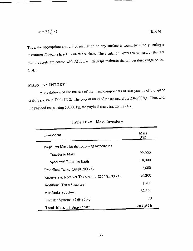
ni = 2 I_- 1 (III-16)
Thus,the appropriateamountof insulationon any surfaceis found by simply settinga
maximumallowableheatflux on thatsurface.Theinsulationlayersarereducedbythefact
that thestrutsarecoatedwith A1foil which helpsmaintainthetemperaturerangeon the
Gr/Ep.
MASS INVENTORY
A breakdown of the masses of the main components or subsystems of the space
craft is shown in Table III-2. The overall mass of the spacecraft is 204,900 kg. Thus with
the payload mass being 50,000 kg, the payload mass fraction is 24%.
Table III.2: Mass Inventory
Component Mass
(k_)
Propellant Mass for the following maneuvers:
Transfer to Mars
Spacecraft Return to Earth
Propellant Tanks (39 @ 200 kg)
Receivers & Receiver Truss Arms (2 @ 8,100 kg)
Additional Truss Structure
Aerobrake Structure
Thruster Systems (2 @ 35 kg)
Total Mass of Spacecraft
99,000
18,000
7,800
16,200
1,200
62,600
70
204,870
133
ORBITAL MECHANICS
Terri Schmitt
In the analysis of the orbital mechanics, all phases of the flight to Mars were
examined. The flight was segmented into (1) the spiral out of Low Earth Orbit; (2) the
transfer to Mars; (3) payload jettison; and (4) the return spiral into Low Earth Orbit.
SIMPLIFYING ASSUMPTIONS
The orbital planes of Mars and Earth lie at approximately 1.8 degrees to each other,
and the eccentricities are 0.017 and 0.093, respectively [29]. This eliminates the need to
consider out of plane orbit changes, and the complexity of elliptical planetary orbits.
Second, the rotational period of the Earth is assumed to be constant, so that the planet
returns to the same location every year. The problem of recapture then becomes much
simpler. Even though these assumptions appear significant, they actually introduce little
error into the calculations.
ESCAPE FROM LOW EARTH ORBIT
Due to the low acceleration inherent in the continuous wave laser propulsion
method, the process of escaping Low Earth Orbit (LEO) requires the use of a constant
thrust spiral. For this mission, LEO is defined to be 500 km above the surface of the
Earth. In this maneuver, enlargement of the spiral radius increases the potential energy of
the spacecraft. Although the spacecraft is thrusting continuously, the velocity decreases as
the orbit radius increases. The rate at which the potential energy increases exceeds the
reduction rate of the kinetic energy, thus resulting in a net increase in the energy of the
system.
To ease the difficulties associated with orbital mechanics, only the two-body
problem is considered. The two-body problem consists of one central mass (i.e. a planet
134
or the Sun)andanorbiting spaceship.Thus,gravitationalattractionexistsonly between
thetwobodiesandall otherexternalforcesareignored.
Only thegravitationalforceandthethrustprovidedto thespacecraftinfluencethe
equationsof motion [30,31]. Theseare
F t g°R2 + rt_2
(Ili-17)
F 0 _ 2i_
(111-18)
where r is the spiral radius, R e is the radius of the Earth, go is the gravitational acceleration
at planet surface _ is the angle from an arbitrary reference line (in radians), M t is the mass
of the spacecraft at time t, and F is the thrust. The equations must satisfy four basic
assumptions [30]:
(1) The mass of the ship is not constant, but decreases
linearly with time due to propellant consumption.
(2) Only one central gravity field is considered at any one
time (the two-body problem).
(3) All orbital maneuvers are coplanar.
(4) No other external forces besides gravity and thrust are
present.
135
Direct integration
increasingradius(SeeFig. III-20).
conditions:
r(O)= ro
t(o)=o
M(O) = Mo
_(0) = 0
of the equations of motion yields a spiral trajectory with
These equations are subjected to the following initial
(III- 19)
where ro is the initial altitude, M o is the initial mass of the ship, and t.te is the gravitational
parameter of the Earth (3.9806 x 10⁵ km3/s 2)
A fourth order Runge-Kutta integration program (See Appendix D) was employed
to integrate these equations to determine the spiral needed to escape the Earth's gravitational
field. By use of this program, the propellant mass is optimized by iteration. The required
spiral time as well as the propellant mass depends upon the transfer orbit needed to
complete the mission.
TRANSFER TO MARS
Once the required velocity is attained, the spacecraft enters a heliocentric transfer
orbit to Mars. The mission can be accomplished with many different transfer orbits. The
limiting factor is the ability to obtain the needed velocity increment (AV) for such missions.
Larger increments require greater propellant consumption, which increases the spacecraft's
mass. Several transfer orbits were considered: Hohmann transfer, a two-year time of
flight fly-by orbit, quasi-impulsive method of jettisoning the payload into the transfer orbit,
and gravitational assist fly-bys of Venus.
136
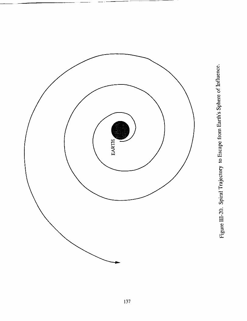
_5
o
m.,
o
r._
o
o¢..)
b-,
°Vml
t"q
137
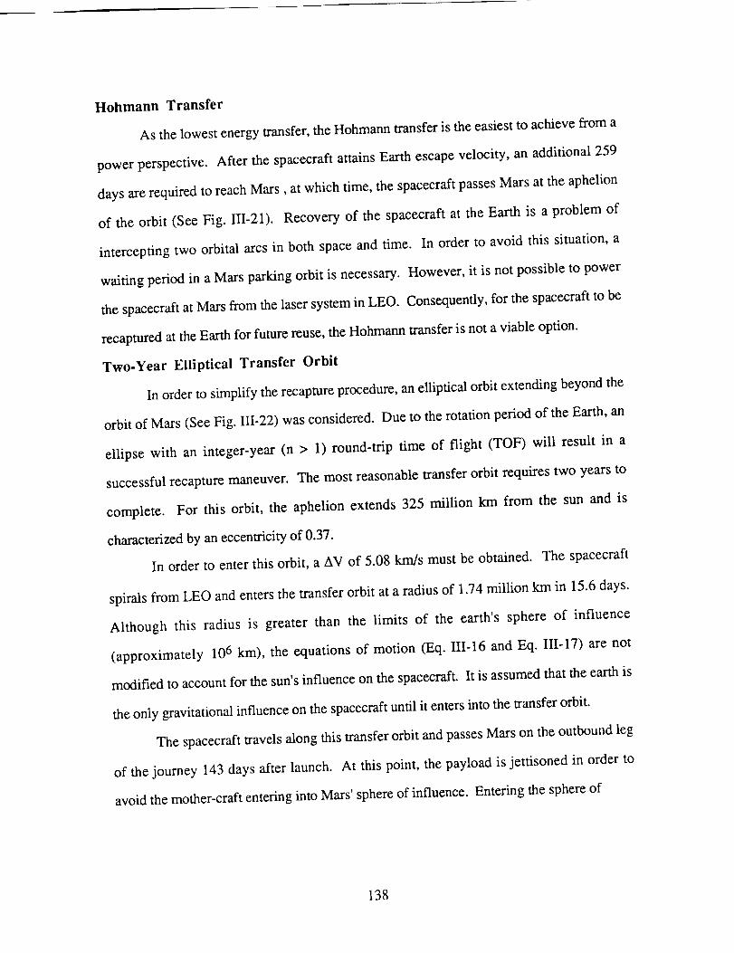
Hohmann Transfer
As the lowest energy transfer, the Hohmann transfer is the easiest to achieve from a
power perspective. After the spacecraft attains Earth escape velocity, an additional 259
days are required to reach Mars, at which time, the spacecraft passes Mars at the aphelion
of the orbit (See Fig. III-21). Recovery of the spacecraft at the Earth is a problem of
intercepting two orbital arcs in both space and time. In order to avoid this situation, a
waiting period in a Mars parking orbit is necessary. However, it is not possible to power
the spacecraft at Mars from the laser system in LEO. Consequently, for the spacecraft to be
recaptured at the Earth for future reuse, the Hohrnann transfer is not a viable option.
Two-Year Elliptical Transfer Orbit
In order to simplify the recapture procedure, an elliptical orbit extending beyond the
orbit of Mars (See Fig. III-22) was considered. Due to the rotation period of the Earth, an
ellipse with an integer-year (n > 1) round-trip time of flight (TOF) will result in a
successful recapture maneuver. The most reasonable transfer orbit requires two years to
complete. For this orbit, the aphelion extends 325 million km from the sun and is
characterized by an eccentricity of 0.37.
In order to enter this orbit, a AV of 5.08 km/s must be obtained. The spacecraft
spirals from LEO and enters the transfer orbit at a radius of 1.74 million km in 15.6 days.
Although this radius is greater than the limits of the earth's sphere of influence
(approximately 106 km), the equations of motion (Eq. Ili-16 and Eq. 111-17) are not
modified to account for the sun's influence on the spacecraft. It is assumed that the earth is
the only gravitational influence on the spacecraft until it enters into the transfer orbit.
The spacecraft travels along this transfer orbit and passes Mars on the outbound leg
of the journey 143 days after launch. At this point, the payload is jettisoned in order to
avoid the mother-craft entering into Mars' sphere of influence. Entering the sphere of
138
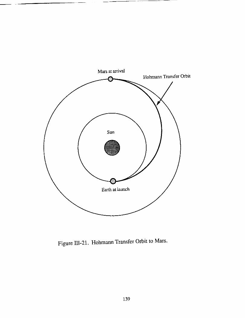
Mars at arrival
Hohmann Transfer Orbit
Sun
Earth at launch
Figure 111-21. Hohmann Transfer Orbit to Mars.
139
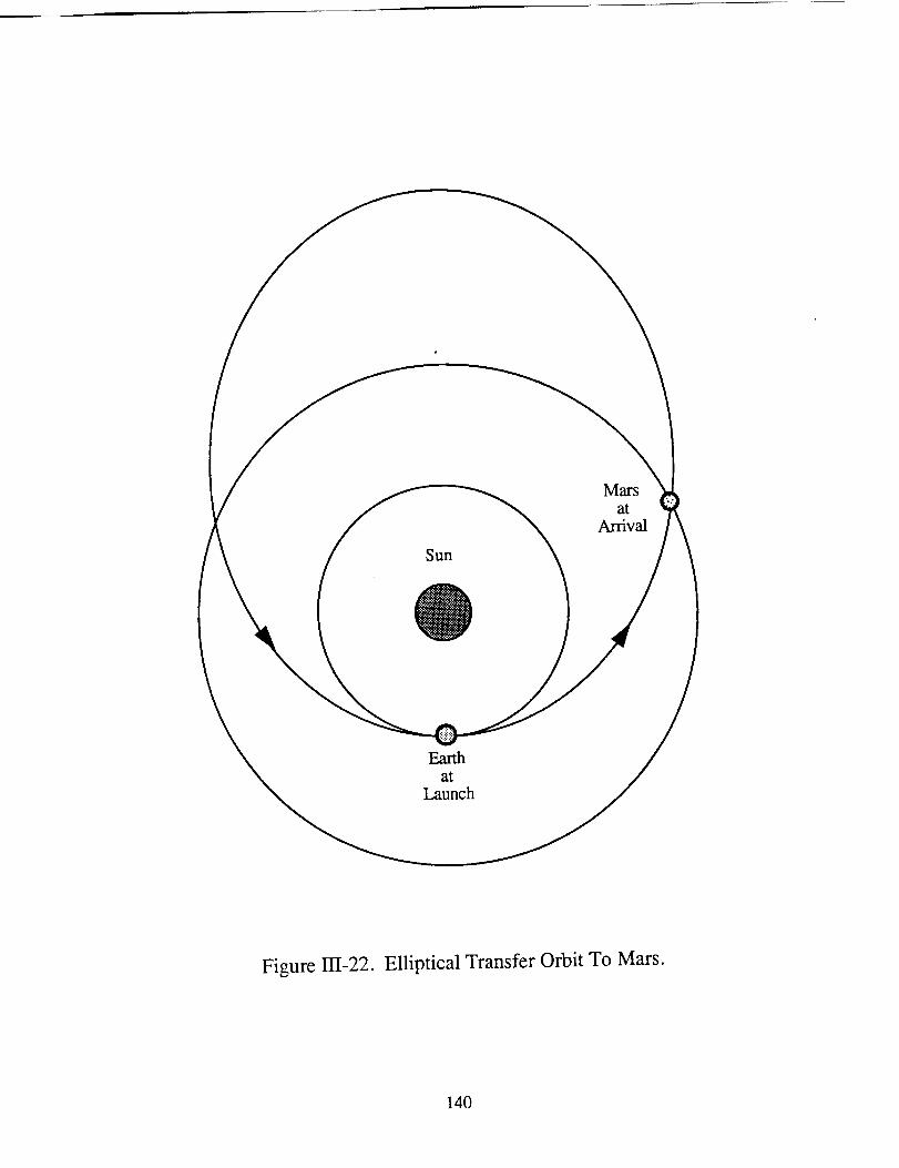
Sun
O
Mars
atArrival
Earthat
Launch
Figure 131-22. Elliptical Transfer Orbit To Mars.
140
influence would require a powered maneuver, which is not possible for the laser system.
The mother-craft returns to the earth on the elliptical trajectory. As the spacecraft nears
Earth, the thrusters onboard the craft are re-enabled for the spiral back into LEO, where the
spacecraft will reside until it is reused.
Quasi-Impulsive Method
A third option was considered in which the payload is jettisoned into the transfer
orbit without the mother-craft leaving the earth's gravitational field. This quasi-impulsive
method requires the spacecraft to thrust for a short duration at the perigee of a series of
elliptical orbits. Detailed analysis of this maneuver is presented in Section II of this report.
The short thrusting cycles require less propellant to complete the mission, which
contributes to the lower initial spacecraft mass of approximately 88,000 kg. An actual
design of the spacecraft could not be completed in time, so the dry mass of the craft was
estimated as 10,000 kg. Since the spacecraft attains a velocity 0.75 km/s below the
required velocity for a Hohmann transfer, chemical propellants are needed to jettison the
payload assembly into the transfer orbit to Mars. After the payload is jettisoned, the
spacecraft returns to LEO to await reuse.
The maximum perigee radius for this orbit, which is attained in approximately 60.5
days, does not exceed 8,500 km. This burn distance determines the size of the laser
system's optical components. The transmitter at the laser platform retains its 13.3 m
diameter. Similarly, the 9 m diameter of the LRU receiver remains constant. The LRU
transmitter and the spacecraft's receiver are 10.7 m and 7.6 m, respectively.
Detailed analysis of this quasi-impulsive method has yet to be completed. Further
investigation is necessary in many areas, such as degradation to the thrusters and changes
in the laser system, before this method is implemented. However, this method offers
versatility by using the spacecraft as an orbital transfer vehicle (OTV).
141
Planetary Fiy-bys
Gravitational assists from neighboring planets are commonly used in unmanned,
interplanetary exploration missions. However, this method requires powered maneuvers
far from the earth. The laser system stationed in LEO does not have the capability of
transmitting the laser energy to the required distances. For this reason, planetary fly-bys
are not possible for the laser propelled spacecraft.
Launch Windows
Interplanetary travel is determined by the launch windows. The alignment of the
Earth and the target planet occurs at regular intervals. In the Earth-Mars system, the
synodic period is 2.13 years [29]. This is the time for any given angle between the two
planets to repeat itself, and thus missions to Mars may only occur at intervals of this
period.
PAYLOAD JETTISON
Only the two-year elliptical transfer is suitable for the laser spacecraft. As the
spacecraft passes Mars on the outbound leg of the transfer orbit, the cargo is jettisoned
while the spacecraft is outside Mars' sphere of influence. The payload performs a chemical
bum to bring it into Mars' atmosphere, where it performs an aerobraking maneuver to enter
into a Mars parking orbit. Details of the aerobraking scheme are presented in Appendix A.
The aerobraking system and the payload have a combined mass of 62,660 kg, which
includes the needed propulsion mechanism to place the payload into a Mars parking orbit.
RECAPTURE AND RETURN SPIRAL INTO LEO
Recapture and reuse of the spacecraft are major mission considerations which
determine the choice of the transfer orbit. As the returning spacecraft approaches the earth,
the continuous wave laser thrusters are re-activated for the inbound spiral maneuver to enter
into LEO. This spiral is very similar to the outbound spiral used to enter the transfer orbit.
142
Theinboundspiral requiresonly 2.61daysto completebecausethemassof thereturning
spacecraftis significantlylessthatwhenoutbound.Oncethespacecraftis backin LEO, it
is refueledandrefittedwith newcargo.Theuseof atwo-yearelliptical transferallowsthe
spacecraftto begin its missionwith a minimal amountof waiting. A total flight time of
748.2days,which includestheoutboundandinboundspiraltime,is necessaryto complete
themission.
143
CONCLUSION
Melanie MillerTerri Schmitt
The Solar Pumped Laser (SPL) propelled spacecraft indirectly uses solar flux as its
primary energy source. The incident flux is converted into two 6 MW CO 2 laser beams by
means of indirect solar pumping. Through a transmission system, including six orbiting
laser relay units and two laser platforms, the laser beams are directed to inflatable receivers
onboard the spacecraft. The beams are then redirected, via an optical train, into two
continuous wave (CW) laser thrusters. Within the absorption chamber of each thruster, the
incident laser energy is absorbed by a hydrogen plasma which then transfers heat to the
surrounding hydrogen propellant flow. Each CW thruster is capable of producing 600 N
of thrust with a specific impulse of 1,260 s.
The initial spacecraft mass of 204,900 kg includes the 117,000 kg of hydrogen
propellant needed to complete the orbital maneuvers necessary for the spacecraft's mission
to Mars. Since the spacecraft is designed to transport 50,000 kg of payload, the payload
mass fraction of the SPL powered spacecraft is 24%.
The SPL system has many difficulties inherent in the design. For example, the
current design assumes that by the time it would be implemented, the combination of six
1 MW beams in phase to produce the desired 6 MW laser would be feasible.
Transmission of the high powered beam over great distances also poses a significant
obstacle. With current technology, it is possible to accurately track the beam for only
one-seventh of the required burnout distance. Without accurate tracking, there will be a
risk that the spacecraft may not receive the laser energy. The CW thruster design is mainly
in the theoretical stages and actual testing of the design using hydrogen propellant has not
yet been performed. Because of the high temperatures associated with laser energy
absorption, current material limitations are also an important issue.
144
Thecurrentresearchindicatesthatthesystemmaynotbepractical. This studyhas
assumedthat the necessarylaserplatformsand relay units will be placedin orbit and
availablefor use. Thecostassociatedwith theengineering,manufacturing,launchingto
orbit,andassemblingof suchalasersystemshasnot beenestimated;however,it is likely
thatthecostwill besohigh astorenderthesystemimpracticalin theforeseeablefuture.
Preliminary researchhas indicated that the SPL propelled spacecraftmay be
redesignedasanorbital transfervehicle(OTV). Oneof thesalientdifficulties,trackingthe
spacecraftover long distancesfor transmissionof the laserbeam,wouldbeminimizedif
thevehiclewereonly requiredto transportpayloadwithin theEarth'ssphereof influence.
An OTV requiresalower propellantmass,andthus,resultsin anincreasedpayloadmass
fraction. Further researchinto the applicationof laserpropulsion for orbital transfer
vehicles may increase the feasibility of the concept of a laser powered spacecraft.
145
NOMENCLATURE
A
cp
CW
D
EVA
F
go
Gr/Ep
h
hn
I
lab
Isp
It
Io
K
LEO
LRU
,h
Mi
Mo
Mt
n
ni
P
nozzle throat area
specific heat at constant pressure
Continuous Wave
diameter
extravehicular activity
thrust
gravitational acceleration
Graphite/Epoxy
enthalpy
altitude of LRUs
intensity of incident radiation
energy absorbed
specific impulse
transmitted radiation intensity
incident laser radiation intensity
empirically derived constant
Low Earth Orbit
Laser Relay Unit
mass flow rate
total mass of insulation
initial mass of the spacecraft
mass at time t
number of LRUs
number of insulation layers
pressure differential
146

Po
P
Pj
Ploss
q
r
ro
tv
R
Re
RP
S.F.
t
To
TOF
tw
U
Y
Yn
Z
chamber pressure
incident laser power
jet power
power losses
heat flux allowed at composite surface
spiral radius
initial altitude
radius of chamber
gas constant
radius of the Earth
Repetitively Pulsed
factor of safety
window thickness
chamber temperature
time of flight
chamber wall thickness
velocity
yield strength
minimum beam approach altitude
distance between transmitter and receiver
o_1
E
¢
Y
absorption coefficient
percent dissociation
emissivity
angle from reference line (rad)
ratio of specific heats
wavelength of the laser
147
p.
11
On
P
Po
0
gravitational parameter of the Earth
efficiency
half-angle between LRUs
transmitter radius
receiver radius
hoop stress
Subscripts
c chamber
e exhaust
A dot above a variable ( ° ) indicates a time derivative.
successive time derivatives.
All values are in MKS units.
Successive dots indicate
148
REFERENCES
. Kantrowitz, A., "Propulsion to Orbit By Ground-Based Lasers", Astronautics and
Aeronautics, Vol. 10, pp. 74-76, May, 1972.
. Jones, L. W. and D. R. Keefer, "NASA's Laser-Propulsion Project", A_tronautics
and Aeronautics, Vol. 20, pp. 66-73, 1982.
° SDIO/DARPA, Volume 1--Executive Summary, Workshop on La_¢r Propulsion.
proceedings, Lawrence Livermore National Laboratory, July, 1986.
° Huberman, M. et al., "Investigation of Beamed Energy Concepts for Propulsion",
Vol. I and II, AFRPL-TR-76-66, Oct., 1976.
. Glumb, R. J. and H. Krier, "Concepts and Status of Laser-Supported Rocket
Propulsion", A_rron_lutics and Aeronautics, Vol. 21, pp. 70-79, Aug., 1983.
. Eskridge, R. H. et al., "An Experimental Study of Laser Supported Plasmas for
Laser Propulsion", NASA TM-86583, Marshall Space Flight Center, Jan., 1987.
7. Deak, A., Rocket Research, Redmond, WA., Private Communication, May, 1989.
. Keefer, D. R. and H. Crowder, "A Two-Dimensional Model of the Hydrogen
Plasma for a Laser Powered Rocket", AIAA Paper No. 82-0404, Jan., 1982.
9. The Harshaw Chemical Company, "High Power Laser Optics", TP-120478, 1989.
149
10. Nestor,O. H. et al., "LargeDiameterPolytranNaC1Windows for CO2
TheHarshawChemicalCompany,Solon,Ohio,TP-0403772M,1989.
Lasers",
II. Conrad,R. W. et al., "Laser-supportedCombustionWaveIgnition in Hydrogen",
Army MissileCommand,TR-RH-80-1,1980.
12. Moody, D. C., "Maintenance of a Gas Breakdown in Argon Using 10.6
Radiation",Journal of Applied Physics. Vol. 46, No. 6, June, 1975.
13. Brooks, R., University of Washington, Aerospace and Energetics Research
Laboratory, Private Communication, March, 1989.
14. Taussig, R., et al, "Solar-Pumped Lasers for Space Power Transmission", AIAA
Paper No. 79-1015, June, 1979.
15. Frisbee, R. H., J. C. Horvath, and J. C. Sercel, "Space-Based Laser Propulsion
for Orbital Transfer", JPL D-1919, Jet Propulsion Laboratory, Pasadena, CA,
1984.
16. Mattick, A. T. and A. Hertzberg, "Liquid Droplet Radiator Technology Issues", In
$pa_e Nuclear Power Systems 1984, Orbit Book Company, Malablar, FL, 1985.
17. Soales, R., CVI, San Diego, CA, Private Communication, March, 1989.
18. Taussig, R., E. Klosterman, and H. Willenberg, "Space Laser Power
Transmission, Task IV Final Report", Contract No. NAS 3-22477, Mathematical
Sciences Northwest, Inc, July, 1981.
150
19. Hertzberg, A., K. Sun, and W. Jones, "Laser Aircraft", Astronautic_ and
Aeronautics, Vol. 17, pp. 41-49, March, 1979.
20. "Laser Rocket System Analysis", Lockheed Missiles and Space Co., NASA
CR-159521, Sept., 1978.
21. Cleven, C., Jet Propulsion Laboratory, Private Communication, May, 1989.
22. Kopf, T., Jet Propulsion Laboratory, Private Communication, May, 1989.
23. Allcock, Harry R., "Polyphosphazenes: New Polymers with Inorganic Backbone
Atoms", Science, Vol. 193, Sept., 1976.
24. Heard, W. L., and J. J. Watson, "Results of the ACCESS Space Construction
Shuttle Flight Experiment", AIAA Paper No. 86-1186-CD, June, 1986.
25. Mikulas, M. M. and H. G. Bush, "Design, Construction, and Utilization of a
Space Station assembled from 5-meter Erectable Struts", NASA TM-89043,
Oct., 1986.
26. Tompkins, S. S., "High Strength A1 Alloys for Graphite Reinforced Metal Matrix
Composites", NASA TM-89037, 1986.
27. Hedgepath, J. M., "Support Structures for Large Infrared Telescopes", NASA-CR-
3800, July, 1984
151
28. Dursch,H. W. and C. L. Hendricks, "ProtectiveCoatingsFor CompositeTubes
In SpaceApplications",NASA-CR-178116,1986.
29. Bate,R. R., D. D. Mueller, and J. E. White, Fgndam_ntal_ of Astrodynamics,
Dover Publications, New York, N.Y., 1971.
30. Stuhlinger, E., "The Flight Path of an Electrically Propelled Space Ship", Jet
Propulsion. Vol. 27, pp. 410-414, 1957.
31. Stuhlinger, E., Ion Propulsion for Space Flight, McGraw-Hill, New York, 1964.
152
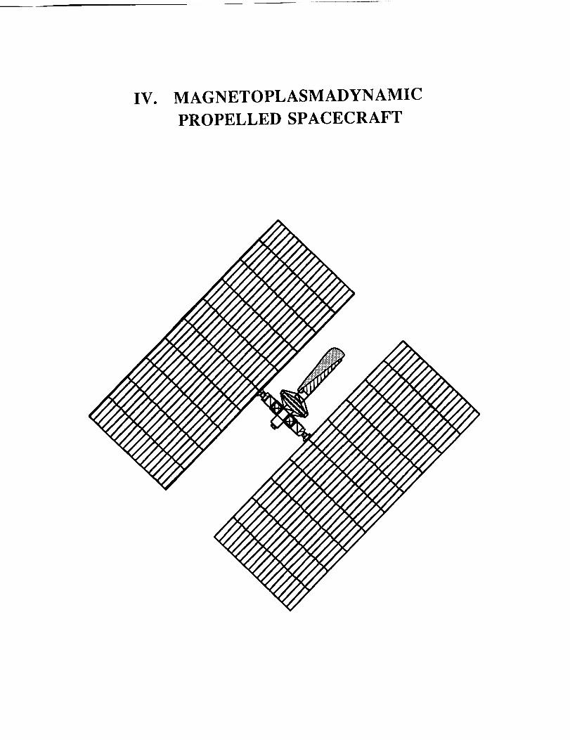
IV. MAGNETO PL AS M ADYN AMI C
PROPELLED SPACECRAFT
INTRODUCTION
Jacqueline Auzias de Turenne
Magnetoplasmadynamic (MPD) propulsion was discovered by Adriano Ducati in
1964 [ 1,2]. Ducati had been experimenting with a conventional electrothermal arcjet when
he lowered the propellant mass flow, along with the chamber pressure, thus developing a
3,000 A current across the anode and the cathode and giving rise to a self-induced magnetic
field. He also observed exhaust velocities in the range of 106 m/s and a greatly reduced
erosion rate at each electrode.
For the first time, researchers had a practical, steady, electromagnetic thruster.
Earlier efforts had resulted in operational thrusters with large, bulky electromagnets, which
made these thrusters hardly suitable for space flight. Without the additional burden of
external magnets, the promising new MPD thrusters were considerably more compact
devices. Due to the inherent limitation of the new propulsion units to produce thrusts only
on the order of tens to hundreds of newtons, however, MPD propulsion is suitable only for
exoatmospheric missions, for which it has become a viable alternative to ion propulsion.
Experimental MPD thrusters have produced thrust levels as high as 2,000 N [2].
Higher thrust levels, though, also correspond to increased power requirements.
Consequently, the thrust performance of MPD propulsion in space is limited by the amount
of power practically available. Exhaust velocities up to 50,000 m/s [2], indicating
correspondingly high specific impulses, however, suggest MPD propulsion as a promising
option for extended, deep space missions.
This section of the report presents the design of an MPD propelled cargo spacecraft
for Mars missions. The spacecraft uses MPD thrusters producing 100 N of thrust at Earth,
diminishing to 40 N of thrust at Mars, with a constant specific impulse of 2,490 s. The
four main design aspects of the MPD propelled spacecraft include the MPD propulsion
system, the solar power supply, the structural analysis, and the orbital mechanics. This
preliminary design analysis illustrates the feasibility of a solar-powered MPD propelled
spacecraft for Mars missions.
154
THE MPD THRUSTER
R. Jay WornathJohn Thorpe
The steady state magnetoplasmadynamic arc thruster, depicted in Fig. IV-l, is a
propulsion device capable of high specific impulses [2]. The MPD device produces thrust
using electrical power in the form of a high current arc to ionize the incoming propellant
and accelerate the resulting plasma to high exhaust velocities. The high exhaust velocities
lead to specific impulses which enable an MPD propelled spacecraft to deliver a high
payload mass with a relatively low propellant mass. This section will examine several
areas: 1) the theory of the MPD thruster, 2) the thruster design and configuration for
specific mission requirements, 3) the propellant type and propellant acquisition device, 4)
the thermal protection of the propellant tank, and finally, 5) the component masses.
THRUSTER THEORY
Understanding the basic principles of the MPD thruster is necessary in order to
design a thruster and a thruster configuration for a specific mission. As mentioned above,
the thrust is a result of a high current arc between the anode and cathode of the MPD
thruster. This azimuthally symmetric diffuse arc current, shown in Fig. IV-1, creates an
azimuthal magnetic field, B 0, which interacts with the current flow to produce a Lorentz
body force on the propellant gas. Two components of this magnetogasdynamic interaction
provide the accelerating force on the plasma. The first, fz, is referred to as electromagnetic
"blowing." This component is the axial accelerating force produced by the interaction of
the radial component of arc current, Jr, with the self-generated azimuthal magnetic field.
The blowing force provides the majority of the thrust for the engine. The second
component of magnetic interaction is known as electromagnetic "pumping," fr- It is
produced by the interaction of the axial arc current, Jz, with the azimuthal magnetic field.
155
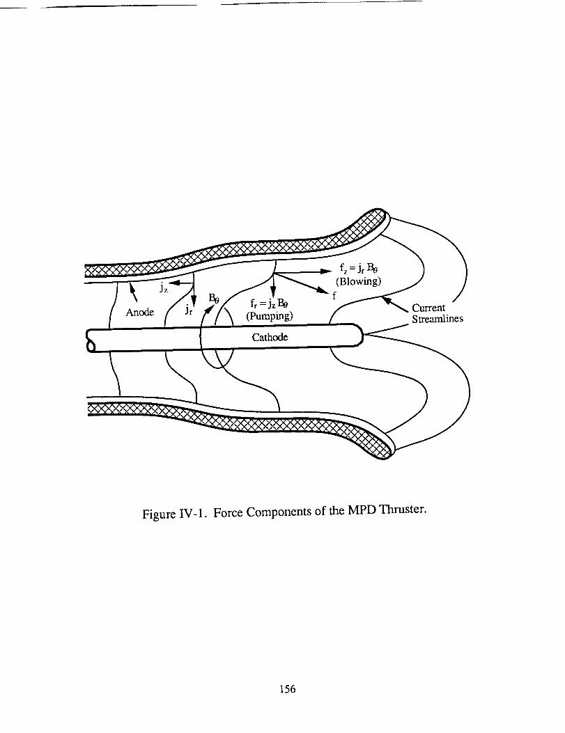
Anodefr =jzB0
(Pumping)
Cathode
fz=Jr Be
(Blowing)
f
CurrentStreamlines
Figure IV-1. Force Components of the MPD Thruster.
156
Thepumpingforceestablishesaradial gradientin thegasdynamicpressurewhich results
in a reactionforce on the cathode.The high dynamicgastemperatures,typically on the
orderof 104K or higher [3], alsocontributeto anaccelerationof theplasmathroughthe
"magneticnozzle"formedby theself-field. Theresultof thesetwo processesaccelerates
theplasmato speedsup to 50,000m/s.
The performanceof the MPD thrustercanbe analyzedusing the relationships
presentedin thefollowing four equations.Theoretically,thethrust,F, is predictedto be
proportionaltothesquareof thearccurrent,J [3]:
F = bJ2 (IV-l)
wheretheconstantof proportionality,b, is afunctionof geometry:
/.oil/a/+ o.751b = _47t _- _rc I (IV-2)
where ra and rc correspond to the radius of the anode and cathode respectively, and/a o is
the permeability of free space (I.to = 4_ x 10 -7 henry/m). The empirical relationship in
Eq. IV-2 indicates that the total electromagnetic thrust is not dependent on the shape of the
arc, but only on the ratio of the anode and cathode radii.
As with any propulsion system an MPD thruster has inherent limitations. The
performance of the MPD has been found to be limited by a critical value of J2/m [5],
known as "onset." Onset is typically associated with voltage oscillations, rapid erosion of
the cathode, and other instabilities. The critical value of J2/m is solely a function of thruster
geometry and propellant properties, and can be approximated by the following equation [5]:
(IV-3)
157
wheree is theelectroncharge,equalto 1.6x 10⁻¹⁹coulomb,NOis Avogadro'snumber,
equalto 6.02x 10²³/gm-mole,andEi andM aretheionizationpotentialandthemolecular
weightof thepropellant,respectively.
Theoverall efficiency,rh definedastheratio of theexhaustjet powerto the input
electricalpower,canbeapproximatedasfollows[4]:
Il = F22ria.JV (IV-4)
wherem is themassflow rate,andV is thevoltagedrop acrossthethruster.
Severalfactorswork to decreasetheefficiencyof theMPD thruster.Thetwo most
significantlossesareheattransferlossesand"frozenflow" losses.Theheattransferlosses
arein theform of radiationfrom thecathodetip, radiationfrom theexhaustjet, andheating
of theanode.The"frozenflow" lossesaredueto unrecoveredinternalenergyof thegasin
theexhaustjet. These"frozenflow" lossesresultfrom the ionized gas re-combining after
exiting the thruster.
THRUSTER DESIGN
The MPD arc thruster for this Mars mission is a relatively compact device, as
shown in Fig. IV-2. The characteristics of this thruster were determined by adapting the
MPD thruster to the specific requirements for a solar powered Mars mission. It has been
determined, as will be explained later in this section, that optimal performance will be
achieved if each thruster produces 20 N of thrust. Knowing the values for thrust,
efficiency, and onset, Eq. IV- 1 through Eq. IV-4 can be manipulated to determine the mass
flow rate of propellant, the power requirement, and the current and voltage requirements.
Power conversion efficiencies as high as 40% have been achieved in experimental tests of
the MPD thruster [6]. It has also been shown that the critical value of onset, J2/m, occurs
at values on the order of 80 kA2/g/s [7]. Assuming a typical value of 10 for the ratio ra/r c
158
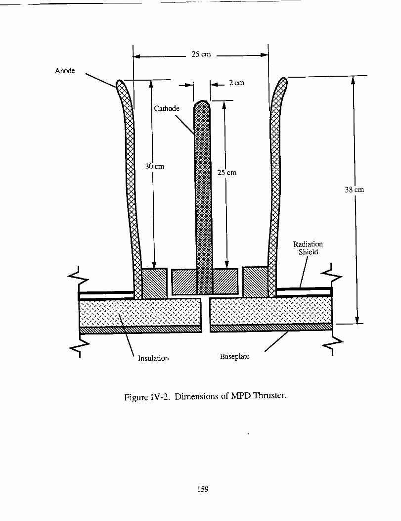
Anode
25cm
30cm
RadiationShield
38cm
ii!!ii!!iiiiii iii!!iiiiiii!i!iiiiiii!!i!iiiilIiiiiiiiii!iiiiiii!iiiii!ili!i!ii!!i!!!i!ili!i!l,
Figure IV-2. Dimensions of MPD Thruster.
159
fixes theconstantof proportionality,b, in Eq. IV- 1. The resultis ananode,which forms
thenozzleof thedevice,with aninnerdiameterof 20cm,anexit diameterof 25cm,anda
lengthof approximately30cm from thebaseplateto thenozzleexit. Thecathodehasa
diameterof 2.0cm andalengthof 25cm,alsomeasuredfrom thebaseplate.Eachthruster
requires0.61MW of powerat acurrentof 8.1kA andapotentialdifferenceof 75V. This
current and geometryrequiresa massflow rate of 0.82 g/s and producesan exhaust
velocity of 24,400m/s, correspondingto a specificimpulseof 2,490s. The anodeand
cathodeof the thruster must withstandhigh temperaturesso both are constructedof
tungsten.Thebaseplateis alsomadeof tungstenandaboronnitride insulatorseparatesthe
anodeandcathode.
THRUSTER THERMAL MANAGEMENT
Any high powered propulsion device has a significant heat rejection problem in
space. For the MPD thruster, 2% of the electrical energy heats the cathode while 15% of
the electrical energy heats the anode [6]. For the 0.61 MW thruster module the heating of
the cathode does not pose a problem; for the anode, however, heating results in 92 kW of
thermal energy that must be radiated. If an emissivity of 0.5 is assumed for the tungsten
anode, which is achievable if the tungsten surface is slightly roughened, and radiation is
considered to occur from the exterior as well as the interior of the thruster module, an
equilibrium anode temperature of approximately 2,000 K will result. This value is well
under the melting temperature of tungsten.
THRUSTER CONFIGURATION
Many of the design problems of the solar powered MPD thruster stem from its low
thrust to power ratio. The thrust to power ratio of the MPD thruster is currently on the
order of 30 N/MW. When the power is supplied by photovoltaic cells this results in a very
large solar array. At the low thrust levels of a single thruster, 20 N, a spacecraft would
160
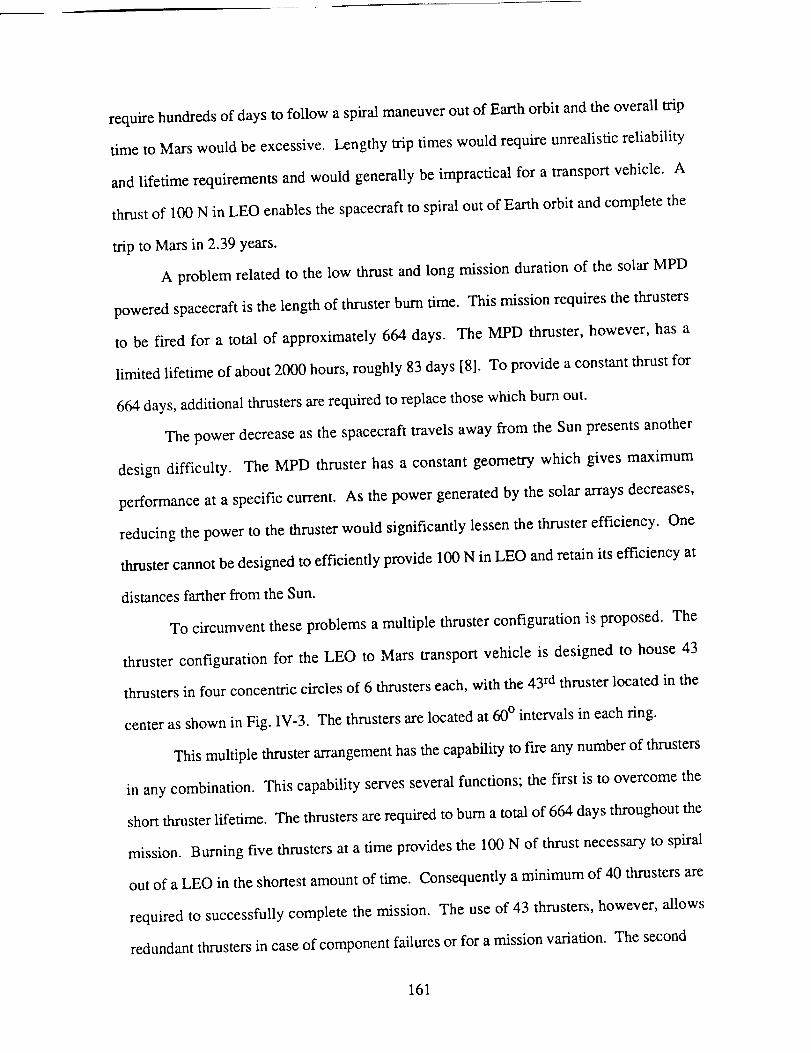
requirehundredsof daysto follow aspiralmaneuveroutof Earthorbit andtheoverall trip
time to Marswouldbeexcessive.Lengthytrip timeswould requireunrealisticreliability
andlifetime requirementsandwould generallybeimpractical for atransportvehicle. A
thrustof 100N in LEO enablesthespacecraftto spiraloutof Earthorbit andcompletethe
trip to Marsin 2.39years.
A problemrelatedto the low thrustandlong missiondurationof the solarMPD
poweredspacecraftis the lengthof thrusterburntime. Thismissionrequiresthethrusters
to be fired for a total of approximately664 days. The MPD thruster, however,hasa
limited lifetime of about2000hours,roughly83days[8]. To provideaconstantthrustfor
664days,additionalthrustersarerequiredto replacethosewhichburnout.
The powerdecreaseasthe spacecrafttravelsawayfrom the Sunpresentsanother
designdifficulty. The MPD thrusterhasa constantgeometrywhich gives maximum
performanceat a specificcurrent. As thepowergeneratedby thesolararraysdecreases,
reducingthepowerto the thrusterwould significantlylessenthethrusterefficiency. One
thrustercannotbedesignedto efficiently provide100N inLEO andretainits efficiencyat
distancesfartherfrom theSun.
To circumventtheseproblemsa multiple thrusterconfigurationis proposed.The
thrusterconfiguration for the LEO to Mars transportvehicle is designedto house43
thrustersin four concentriccirclesof 6 thrusterseach,with the43rdthrusterlocatedin the
centerasshownin Fig. IV-3. Thethrustersarelocatedat 60° intervalsin eachring.
Thismultiple thrusterarrangementhasthecapabilityto fire any number of thrusters
in any combination. This capability serves several functions; the first is to overcome the
short thruster lifetime. The thrusters are required to burn a total of 664 days throughout the
mission. Burning five thrusters at a time provides the 100 N of thrust necessary to spiral
out of a LEO in the shortest amount of time. Consequently a minimum of 40 thrusters are
required to successfully complete the mission. The use of 43 thrusters, however, allows
redundant thrusters in case of component failures or for a mission variation. The second
161
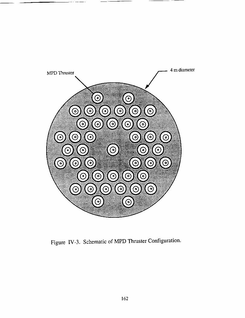
MPDThruster4m diameter
Figure IV-3. Schematic of MPD Thruster Configuration.
162
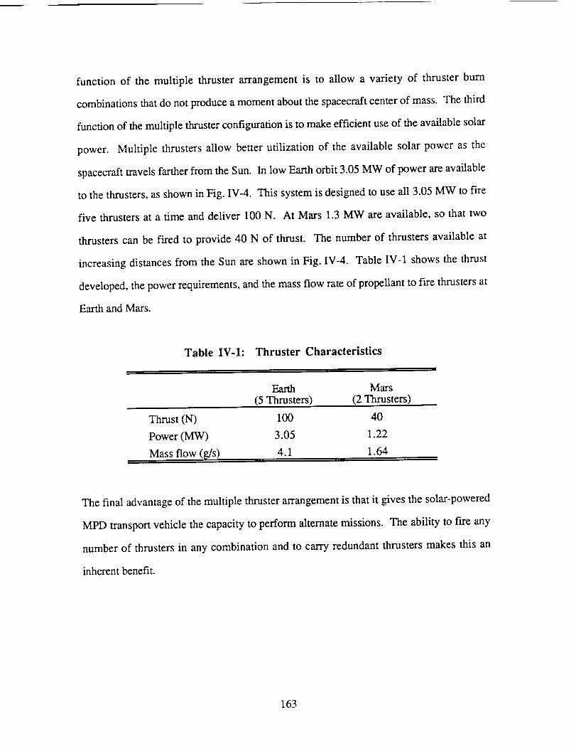
function of the multiple thruster arrangementis to allow a variety of thruster burn
combinationsthatdonotproduceamomentaboutthespacecraftcenterof mass.Thethird
functionof themultiplethrusterconfigurationis to makeefficientuseof theavailablesolar
power. Multiple thrustersallow betterutilization of the available solar power as the
spacecrafttravelsfartherfrom theSun. In low Earthorbit 3.05MW of powerareavailable
to thethrusters,asshownin Fig. IV-4. Thissystemis designedto useall 3.05MW to fire
five thrustersat a time anddeliver 100N. At Mars 1.3MW areavailable,so that two
thrusterscanbe fired to provide40 N of thrust. The numberof thrustersavailableat
increasingdistancesfrom the Sunareshownin Fig. IV-4. TableIV-1 showsthe thrust
developed,thepowerrequirements,andthemassflow rateof propellantto fire thrustersat
EarthandMars.
Table IV-l: Thruster Characteristics
, , I
Earth Mars
(5 Thrusters) (2 Thrusters)
Thrust (N) 100 40
Power (MW) 3.05 1.22
Mass flow (_/s) 4.1 1.64
The final advantage of the multiple thruster arrangement is that it gives the solar-powered
MPD transport vehicle the capacity to perform alternate missions. The ability to fire any
number of thrusters in any combination and to carry redundant thrusters makes this an
inherent benefit.
163
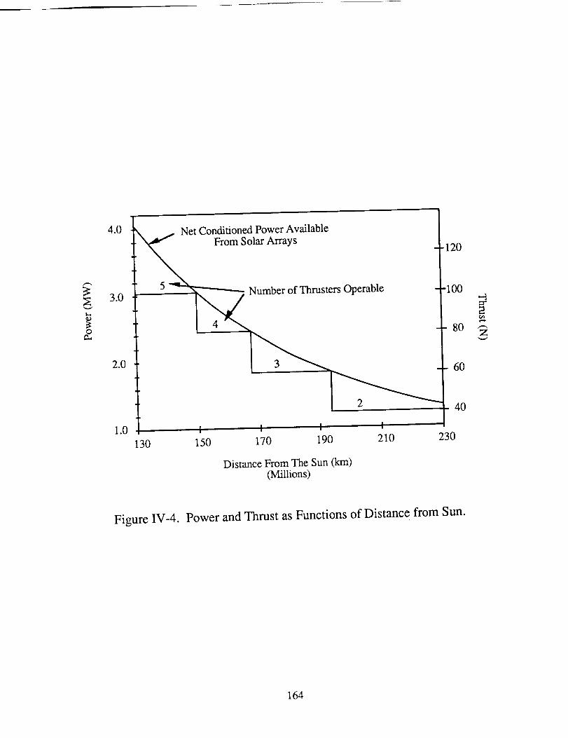
3:
O
4.0
3.0
2.0
1.0
Net Conditioned Power Available
From Solar Arrays-120
5 _Number of Thrusters Operable -100
-- 80
60
40
I I I I
130 150 170 190 210 230
Distance From The Sun (km)(Millions)
7
Figure IV-4. Power and Thrust as Functions of Distance from Sun.
164
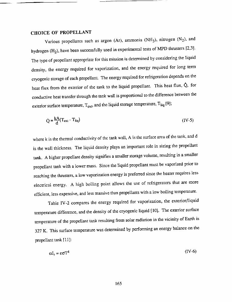
CHOICE OF PROPELLANT
Various propellants such as argon (Ar), ammonia (NH3), nitrogen (N2), and
hydrogen (H2), have been successfully used in experimental tests of MPD thrusters [2,3].
The type of propellant appropriate for this mission is determined by considering the liquid
density, the energy required for vaporization, and the energy required for long term
cryogenic storage of each propellant. The energy required for refrigeration depends on the
heat flux from the exterior of the tank to the liquid propellant. This heat flux, Q, for
conductive heat transfer through the tank wall is proportional to the difference between the
exterior surface temperature, Tex t, and the liquid storage temperature, Tli q [9];
0 = _-{Text - Tliq) (rv-5)
where k is the thermal conductivity of the tank wall, A is the surface area of the tank, and d
is the wall thickness. The liquid density plays an important role in sizing the propellant
tank. A higher propellant density signifies a smaller storage volume, resulting in a smaller
propellant tank with a lower mass. Since the liquid propellant must be vaporized prior to
reaching the thrusters, a low vaporization energy is preferred since the heater requires less
electrical energy. A high boiling point allows the use of refrigerators that are more
efficient, less expensive, and less massive than propellants with a low boiling temperature.
Table IV-2 compares the energy required for vaporization, the exterior/liquid
temperature difference, and the density of the cryogenic liquid [10]. The exterior surface
temperature of the propellant tank resulting from solar radiation in the vicinity of Earth is
327 K. This surface temperature was determined by performing an energy balance on the
propellant tank [11]:
Otis = ec_T 4 (IV-6)
165
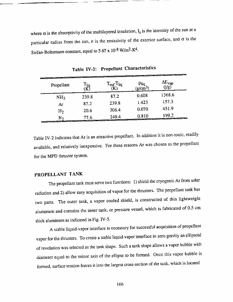
whereotis theabsorptivityof themuhilayeredinsulation,Isis the intensityof thesunat a
particular radius from the sun,Eis theemissivity of the exterior surface,and c is the
Stefan-Boltzmannconstant,equalto 5.67x 10⁻⁸W/m2-K4.
Table IV-2: Propellant Characteristics
Propellant _i_ Text-Tliq [liq AF-va.,(K) (g/cm 3) (j/g)_"
NH3 239.8 87.2 0.608 1368.6
Ar 87.2 239.8 1.423 157.3
H2 20.6 306.4 0.070 451.9
N2 77.6 249.4 0.810 199.2
Table IV-2 indicates that Ar is an attractive propellant. In addition it is non-toxic, readily
available, and relatively inexpensive. For these reasons Ar was chosen as the propellant
for the MPD thruster system.
PROPELLANT TANK
The propellant tank must serve two functions: 1) shield the cryogenic Ar from solar
radiation and 2) allow easy acquisition of vapor for the thrusters. The propellant tank has
two parts. The outer tank, a vapor cooled shield, is constructed of thin lightweight
aluminum and contains the inner tank, or pressure vessel, which is fabricated of 0.5 cm
thick aluminum as indicated in Fig. IV-5.
A stable liquid-vapor interface is necessary for successful acquisition of propellant
vapor for the thrusters. To create a stable liquid-vapor interface in zero gravity an ellipsoid
of revolution was selected as the tank shape. Such a tank shape allows a vapor bubble with
diameter equal to the minor axis of the ellipse to be formed. Once this vapor bubble is
formed, surface tension forces it into the largest cross-section of the tank, which is located
166
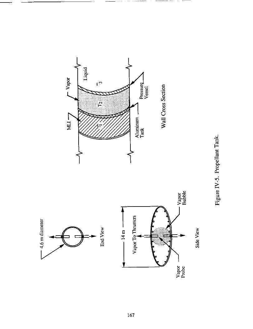
ol_..4
£r..9
°_..i o,m._
>.
A/_iiiiiiE_iiiiiiiii_!_
_iiiiiiiiii_,::::_iiiiiiiiiii_
>-_.,
o,,._
>.
£
,A!
167
at the center,as shownin Fig. IV-5 [12]. The vapor bubble may be formed in the
propellanttankbyrotatingthetankabouttheminoraxis. This is consideredaspartof the
fuelingprocedure.Thedimensionsof thepropellanttankwerechosento hold 170,000kg,
correspondingto 120m3of liquid Ar, to containavaporbubbleof sufficientsize,andto fit
insidethecargobayof thespaceshuttle.Consequentlythetankis 14m longwith a 4.6m
diameter.
PROPELLANT ACQUISITION
In order to fulfill the requirement of the mass flow of propellant to the thruster and
prevent the passage of liquid Ar into the vapor cooled shield surrounding the tank, a vapor
acquisition system is necessary. Since the location of the vapor bubble is known, the
propellant vapor can be extracted directly from the bubble using vapor probes as shown in
Fig. IV-5. These probes, or tubes, are constructed of a ceramic composite material which
demonstrates low thermal conductivity and high strength. The vapor withdrawn from the
pressure vessel passes through a valve where it is either directed through the surrounding
vapor shield or to the thrusters. During thrust conditions, the valve is closed to the vapor
cooled shield and opened to the thrusters providing the proper mass flow of propellant to
the thrusters. When the thrusters are not in operation, the valve is closed to the thrusters
and opened to the vapor cooled shield permitting vapor to cool the pressure vessel, as will
be explained later.
The valve used in the vapor acquisition device may be represented by the Joule-
Thompson throttling effect if the process is assumed to occur adiabatically with negligible
change in kinetic energy. The assumption of an adiabatic process is valid if the flow
through the valve occurs at a high velocity so that there is neither sufficient time nor area
for heat transfer. Therefore, the total enthalpy of the flow remains constant across the
valve, resulting in a drop in the vapor temperature.
168
PROPELLANT HEATER
In order to supply the thrusters with the required mass flow of vapor during their
operational phase, the boil off rate in the pressure vessel must equal the mass flow rate of
propellant to the thrusters. To fulfill the mass flow requirements, a series of small electric
heating coils are placed circumferentially on the inside of the pressure vessel walls. Since
the location of the vapor bubble is known, the point were the tank wall, liquid, and vapor
intersect is also known. The heating coils corresponding to these thin fluid film locations
can be activated sequentially to generate bubbles which will merge with the larger vapor
bubble due to their proximity and the surface tension of the liquid. In LEO, when 5
thrusters are fired, the mass flow rate required is 4.1 g/s. This corresponds to 650 W of
electrical power needed to heat the coils and vaporize the necessary amount of liquid. As
the distance of the spacecraft from the sun increases and fewer thrusters are used, the mass
flow rate of argon and the electrical power necessary to vaporize the argon are reduced. •
PROPELLANT TANK INSULATION
In order to minimize the heat flux into the cryogenic pressure vessel, a combination
of multilayered insulation and a vapor cooled shielding are used. Multilayer insulation,
MLI, consists of layers of highly reflective metallized polymeric film separated by low
conductivity materials such as dacron or nylon. MLI has an effective conductivity of
0.000017 W/K-m. As shown earlier, the surface temperature for the propellant tank near
LEO is 327 K. Since the surface temperature is known, the heat flux, 01, through the MLI
to the outer tank wall can be determined from Eq. IV-7 below:
QI = _-{T1 - T2) (IV-7)
where T 1 and T 2 are the external surface temperature and the vapor temperature in the vapor
cooled shield, respectively, as shown in Fig. IV-5, and k is the effective thermal
169
conductivity of MLI. The effects of the thin aluminum walls of the vapor cooled shield
were neglected in this approximation.
The Ar gas from the vapor acquisition probes circulates through channels outside
the pressure vessel, absorbing heat from the tank exterior that has penetrated the insulation.
Since there is a drop in the vapor temperature across the valve, the vapor in the vapor
cooled heat shield also serves to cool the liquid in the pressure vessel [13]. The Ar gas is
then reliquefied and returned to the pressure vessel. For a given mass flow the amount of
heat, 02, that can be absorbed by the Ar can be found from:
Q2 = riaCp(T2 - T3} (IV-8)
where Cp, is the specific heat of the Ar vapor, and T 2 and T 3 are the temperatures of the
exiting Ar vapor and the Ar liquid, respectively.
In LEO where the intensity of the Sun is greatest, 4.8 W of thermal energy
penetrate the MLI and reach the propellant tank. When the thrusters are not in operation,
the 4.8 W of heat is removed using a Stirling refrigerator in a process of reliquefaction.
The Stirling refrigerators developed for use in space incorporate magnetic bearings to
suspend a reciprocating compressor and expander. For a power input of 220 W, a
maximum cooling rate of 5 W is achieved [10].
COMPONENT MASSES
A major advantage of the MPD thruster system lies in its low component masses.
Low component masses make it possible to include redundant components at very little
penalty. The masses of the components are shown in Table IV-3. Each thruster (anode,
cathode, and base) has a mass of only 35 kg. To operate each thruster, an assortment of
valves and propellant lines are required. Each thruster requires one valve, estimated to
have a mass of 5 kg, and approximately 5 kg of propellant lines. In addition, engine
170
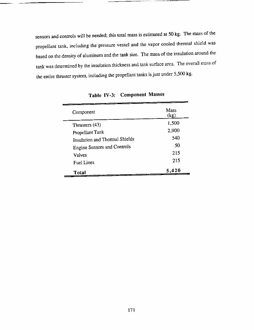
sensorsandcontrolswill beneeded; this total mass is estimated at 50 kg. The mass of the
propellant tank, including the pressure vessel and the vapor cooled thermal shield was
based on the density of aluminum and the tank size. The mass of the insulation around the
tank was determined by the insulation thickness and tank surface area. The overall mass of
the entire thruster system, including the propellant tanks is just under 5,500 kg.
Table IV-3:
Component
Component Masses
Mass
(k_)
Thrusters (43)
Propellant Tank
Insulation and Thermal Shields
Engine Sensors and Controls
Valves
Fuel Lines
Total
1,500
2,900
540
50
215
215
5,420
171
POWER SUPPLY
Eric Haberman
MPD thrusters require a combination of low voltage and high current, thus a high
power level, for efficient operation. The power must be delivered to the thrusters at a
constant 75 V DC. For this specific mission, a thrust level of 100 N requiring 3.05 MW of
power was determined optimum. The necessary power is generated by a photovoltaic array
and conditioned to the levels acceptable for the MPD thrusters and auxiliary power units
such as batteries, stationkeeping, and engine start-up. The design of the photovoltaic array
must take into account the degradation of the photovoltaic cells caused by radiation
encountered in the Van Allen radiation belts [14] and the normal space environment.
PHOTOVOLTAIC SOLAR ARRAYS
Advanced photovoltaic arrays capable of achieving power densities of 300 W/m 2
and 300 W/kg are expected to be available within the next 20 years [15]. The specific
power of 300 W/m 2 applies to a near-earth orbit where the solar flux is approximately
1,380 W/m 2. The solar flux decreases to 565 W/m 2 at Mars, thus reducing the power
density of the cells. Presently, the best array in use produces only 130 W/m 2 at Low Earth
Orbit [ 16].
Currently, there are two main types of photovoltaic cells included in the projections.
These are indium phosphide (InP) and gallium arsenide (GaAs) cells. Gallium arsenide
cells have obtained efficiencies of 21%, while presently the best InP cells are 13.6%
efficient. However, with continuing research and development, InP ceils are expected to
eventually be able to achieve efficiencies in the vicinity of 21% [17,18]. The characteristics
of the two cells are projected to be similar, thus allowing the assumption that a photovoltaic
array constructed from either InP or GaAs cells will be similar in size, mass, and power
output at Beginning Of Life (BOL). Several other types of cells, such as silicon, are under
172
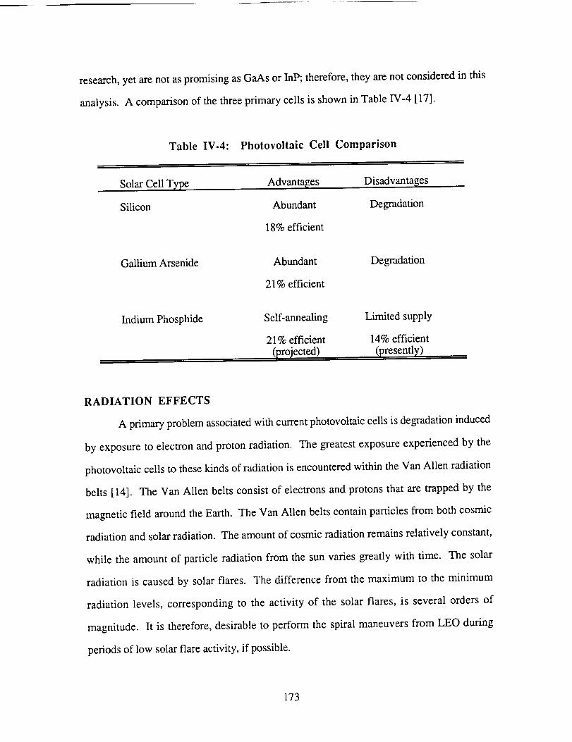
research,yet arenot aspromisingasGaAsor InP; therefore,theyarenotconsideredin this
analysis.A comparisonof thethreeprimary cellsis shownin TableIV-4 [17].
Table IV-4: Photovoltaic Cell Comparison
Solar Cell Type
Silicon
Advantages
Abundant
18% efficient
Disadvantages
Degradation
Gallium Arsenide Abundant
21% efficient
Degradation
Indium Phosphide Self-annealing
21% efficient
(projected)
Limited supply
14% efficient
(presently)
RADIATION EFFECTS
A primary problem associated with current photovoltaic cells is degradation induced
by exposure to electron and proton radiation. The greatest exposure experienced by the
photovoltaic ceils to these kinds of radiation is encountered within the Van Allen radiation
belts [14]. The Van Allen belts consist of electrons and protons that are trapped by the
magnetic field around the Earth. The Van Allen belts contain particles from both cosmic
radiation and solar radiation. The amount of cosmic radiation remains relatively constant,
while the amount of particle radiation from the sun varies greatly with time. The solar
radiation is caused by solar flares. The difference from the maximum to the minimum
radiation levels, corresponding to the activity of the solar flares, is several orders of
magnitude. It is therefore, desirable to perform the spiral maneuvers from LEO during
periods of low solar flare activity, if possible.
173
For the Mars mission, the spacecraftspendsapproximately60 days in the Van
Allen Radiationbelts.Theamountof radiationthattheshipencountersin thebeltsdepends
on severalfactors. Theseincludethe amountof time spentin thevariousregionsof the
radiation belts and the activity of the solar flares. For degradationestimates,it was
assumedthatradiationlevelswere at average intensities throughout the belts.
Indium phosphide and gallium arsenide cells have very different reactions to
radiation exposure, each with definite advantages and disadvantages. With the state of
present technology, GaAs cells would provide the best choice. Of the presently abundant
cells, GaAs has the highest efficiency and is most resistant to radiation. The major
disadvantage of GaAs cells is the amount of degradation that they will experience during
the mission. After traveling through the Van Allen Radiation belts, they will produce
approximately 20% less power than at BOL. Throughout the rest of the mission, these
cells will lose approximately another 3% of their power output due to natural radiation
aging [14,17,19]. In order to contend with the degradation in power output, the size and
mass of the entire photovoltaic array would need to be increased, thus lengthening the
duration of the mission. The mission to Mars would in fact be possible with GaAs cells,
but operation at Mars would be limited by the decreasing efficiency of the cells. A large
cost in refurbishing the spacecraft with new photovoltaic cells, creating a virtually new
spacecraft, would be incurred.
Indium phosphide ceils are a promising alternative to GaAs cells. Although
research on InP cells during the past few years has been limited, a recent interest has
developed. InP cells have one important feature, the ability to regenerate after radiation
damage, through a process known as self-annealing. In an environment where an adequate
amount of thermal energy is available, thermal annealing is accomplished by tailoring the
emissivity of the array in order to maintain the cells at a temperature of 115 ° C. For this
specific Mars mission, the required level of solar intensity is never encountered by the
spacecraft. Therefore, an alternative method of annealing is employed for the mission by
174
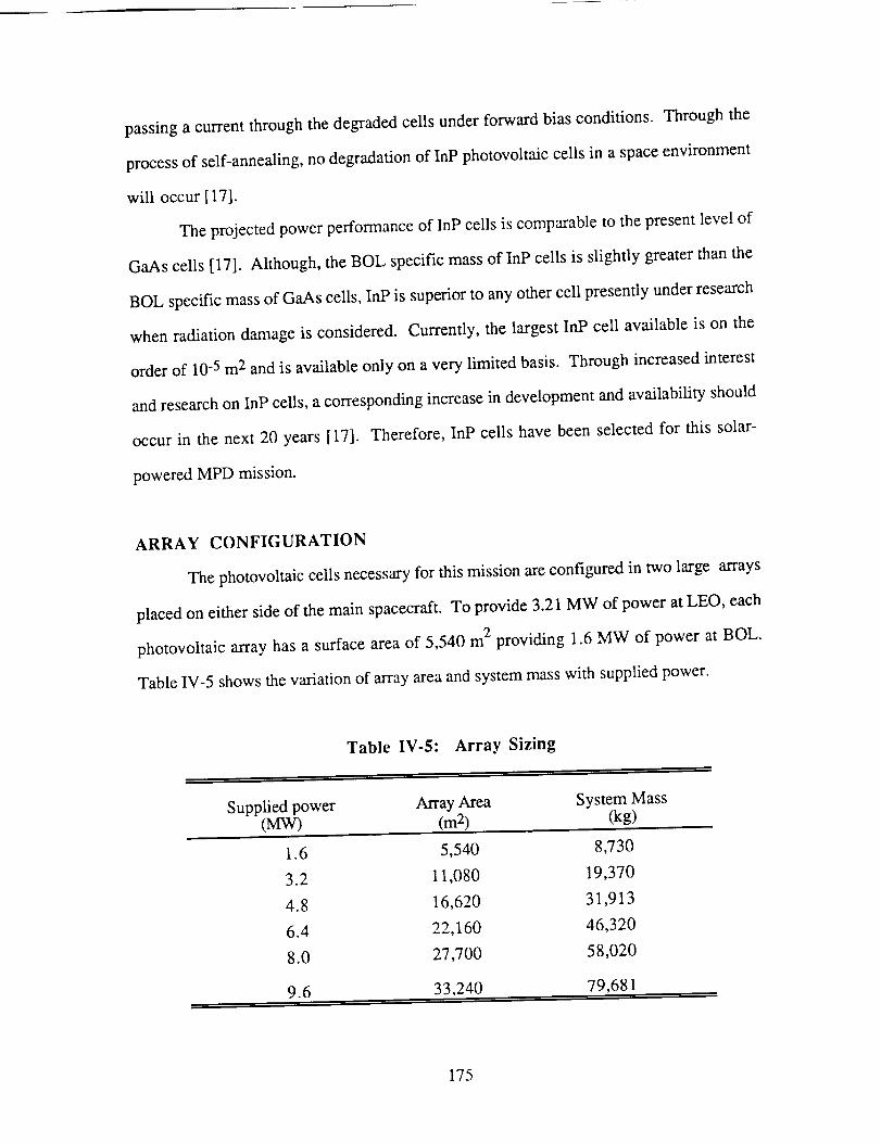
passingacurrentthroughthedegradedcellsunderforwardbiasconditions. Throughthe
processof self-annealing,nodegradationof InP photovoltaiccellsin aspaceenvironment
will occur [17].
Theprojectedpowerperformanceof InP cellsis comparableto thepresentlevelof
GaAscells [17]. Although,theBOL specificmassof InP ceilsis slightly greaterthanthe
BOL specificmassof GaAscells,InPis superiorto anyothercell presentlyunderresearch
whenradiationdamageis considered.Currently,the largestInP cell availableis on the
orderof 10-5m2andis availableonly onavery limited basis.Throughincreasedinterest
andresearchon InP cells,acorrespondingincreasein developmentandavailability should
occur in the next 20 years[17]. Therefore,InP cells havebeenselectedfor this solar-
poweredMPD mission.
ARRAY CONFIGURATION
Thephotovoltaiccellsnecessaryfor thismissionareconfiguredin two large arrays
placedoneithersideof themain spacecraft.To provide3.21MW of poweratLEO, each
photovoltaicarrayhasa surfaceareaof 5,540m2 providing 1.6MW of power at BOL.
TableIV-5 showsthevariationof arrayareaandsystemmasswith suppliedpower.
Table IV-5: Array Sizing
Supplied power Array Area System Mass(MW) (m 2) (kg)
1.6 5,540 8,730
3.2 11,080 19,370
4.8 16,620 31,913
6.4 22,160 46,320
8.0 27,700 58,020
9.6 33,240 79,681
175
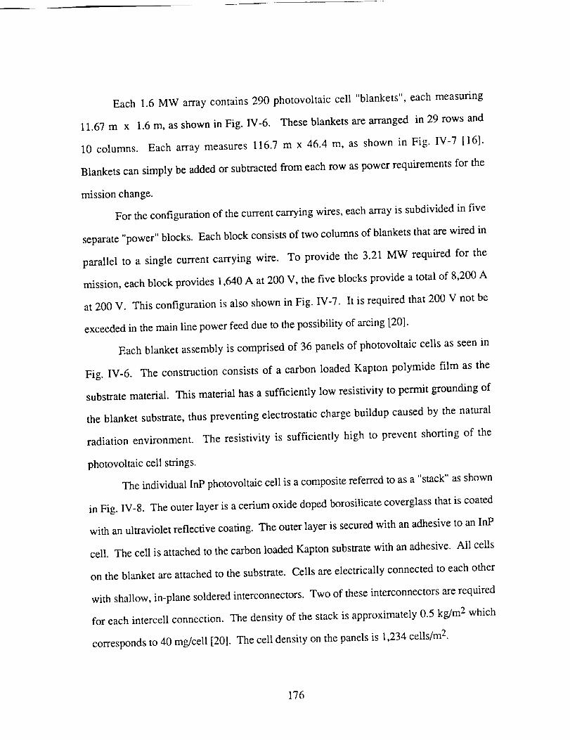
Each 1.6 MW array contains290 photovoltaic cell "blankets",eachmeasuring
11.67m x 1.6m, asshownin Fig. IV-6. Theseblanketsarearrangedin 29 rows and
10 columns. Each array measures116.7m x 46.4 m, as shown in Fig. IV-7 [16].
Blanketscansimply beaddedor subtractedfrom eachrow aspowerrequirementsfor the
missionchange.
For theconfigurationof thecurrentcarryingwires,eacharrayis subdividedin five
separate"power"blocks. Eachblockconsistsof two columnsof blanketsthatarewired in
parallel to a single current carrying wire. To provide the 3.21 MW required for the
mission,eachblock provides1,640A at 200 V, thefive blocksprovideatotal of 8,200A
at 200 V. This configuration is also shown in Fig. IV-7. It is required that 200 V not be
exceeded in the main line power feed due to the possibility of arcing [20].
Each blanket assembly is comprised of 36 panels of photovoltaic cells as seen in
Fig. IV-6. The construction consists of a carbon loaded Kapton polymide film as the
substrate material. This material has a sufficiently low resistivity to permit grounding of
the blanket substrate, thus preventing electrostatic charge buildup caused by the natural
radiation environment. The resistivity is sufficiently high to prevent shorting of the
photovoltaic cell strings.
The individual InP photovoltaic cell is a composite referred to as a "stack" as shown
in Fig. IV-8. The outer layer is a cerium oxide doped borosilicate coverglass that is coated
with an ultraviolet reflective coating. The outer layer is secured with an adhesive to an InP
cell. The cell is attached to the carbon loaded Kapton substrate with an adhesive. All cells
on the blanket are attached to the substrate. Cells are electrically connected to each other
with shallow, in-plane soldered interconnectors. Two of these interconnectors are required
for each intercell connection. The density of the stack is approximately 0.5 kg/m 2 which
corresponds to 40 rag/cell [20]. The cell density on the panels is 1,234 cells/m 2.
I76
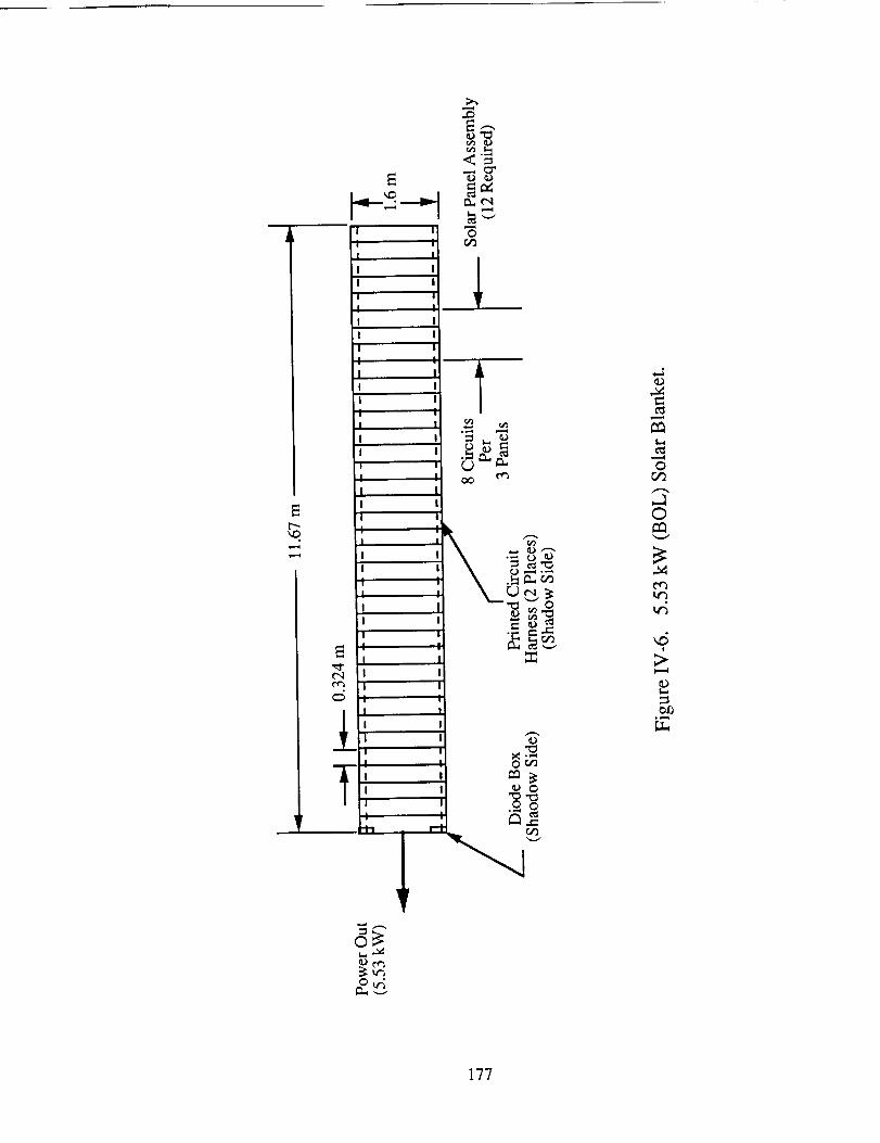
Et'-,-
re%
i I
•t" "t!
I
I I
I I
I II
I
I
I
I
I
4
I
,r=.-4
0
I
' _!
II
!
_rm
L NI
!
1
or_
0
e_
,,5!
>.
177
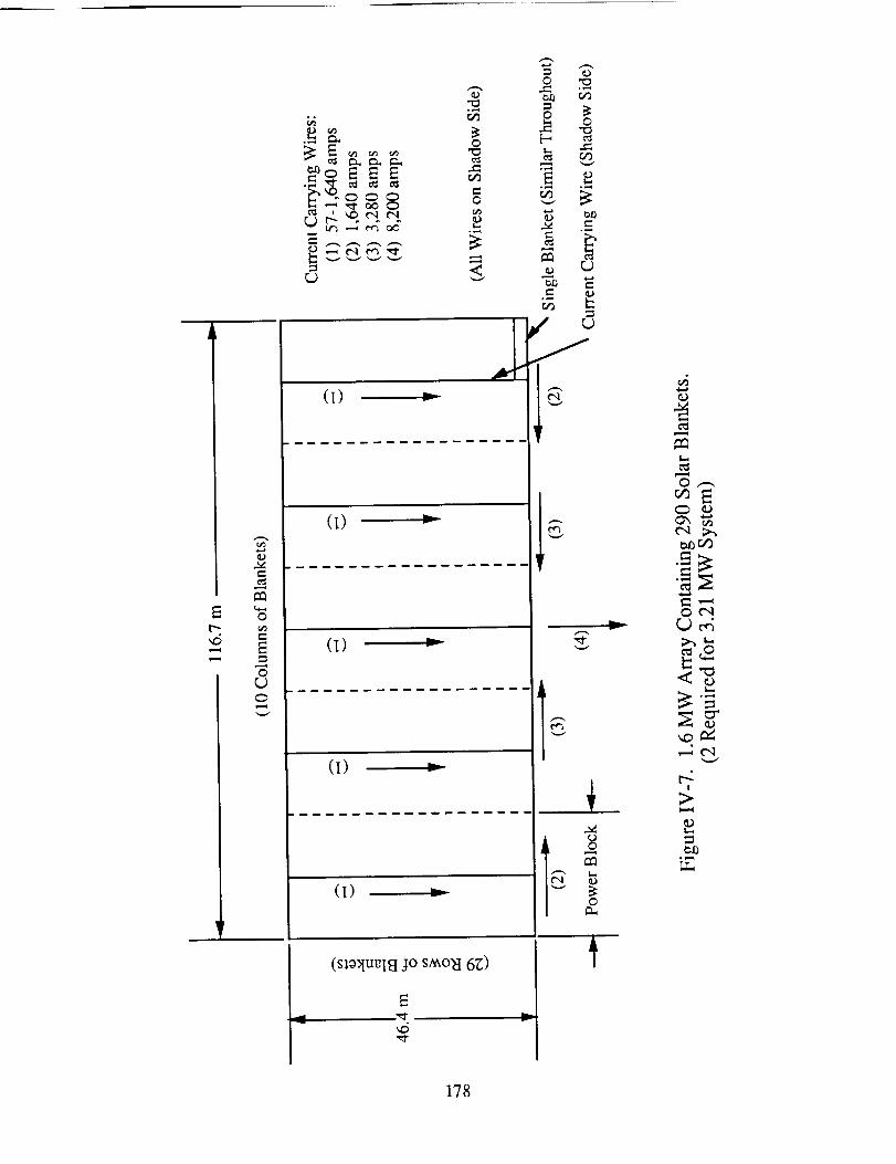
p....
,,6
I=
0
0(J
(t) _
(t) _
y
0
178
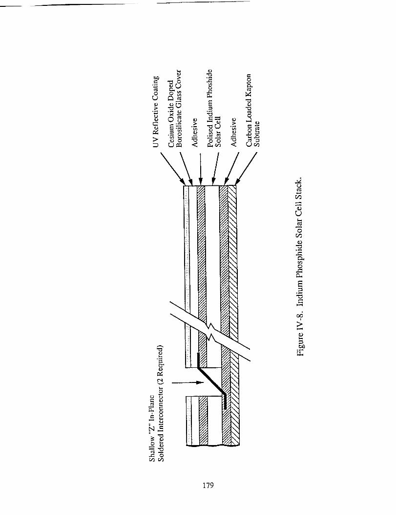
I._.
o o_
.> _
> _o "H
I
!
r'-, Q2_
_ N
2;
" o
oe"
E°_
o o "_
cJ
1
fA
1I
0
r..)_
.//
_/2t
., \1"" \1
!.,
f_
Fs -¢IA _.¢IA¢114_'IA -
¢IA
53.7, \
c_
r_
t_
0r_
0
I
179
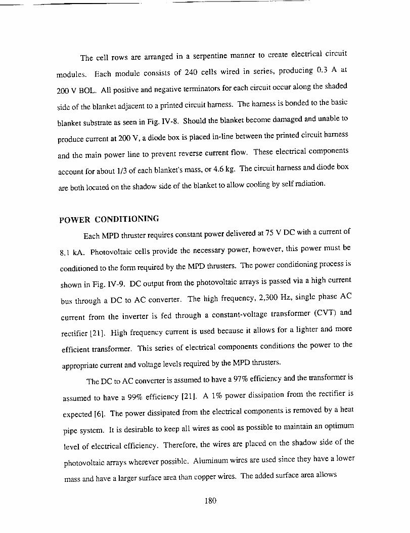
The cell rows are arranged in a serpentine manner to create electrical circuit
modules. Each module consists of 240 cells wired in series, producing 0.3 A at
200 V BOL. All positive and negative terminators for each circuit occur along the shaded
side of the blanket adjacent to a printed circuit harness. The harness is bonded to the basic
blanket substrate as seen in Fig. IV-8. Should the blanket become damaged and unable to
produce current at 200 V, a diode box is placed in-line between the printed circuit harness
and the main power line to prevent reverse current flow. These electrical components
account for about 1/3 of each blanket's mass, or 4.6 kg. The circuit harness and diode box
are both located on the shadow side of the blanket to allow cooling by self radiation.
POWER CONDITIONING
Each MPD thruster requires constant power delivered at 75 V DC with a current of
8.1 kA. Photovoltaic ceils provide the necessary power, however, this power must be
conditioned to the form required by the MPD thrusters. The power conditioning process is
shown in Fig. 1V-9. DC output from the photovoltaic arrays is passed via a high current
bus through a DC to AC converter. The high frequency, 2,300 Hz, single phase AC
current from the inverter is fed through a constant-voltage transformer (CVT) and
rectifier [21]. High frequency current is used because it allows for a lighter and more
efficient transformer. This series of electrical components conditions the power to the
appropriate current and voltage levels required by the MPD thrusters.
The DC to AC converter is assumed to have a 97% efficiency and the transformer is
assumed to have a 99% efficiency [21]. A 1% power dissipation from the rectifier is
expected [6]. The power dissipated from the electrical components is removed by a heat
pipe system. It is desirable to keep all wires as cool as possible to maintain an optimum
level of electrical efficiency. Therefore, the wires are placed on the shadow side of the
photovoltaic arrays wherever possible. Aluminum wires are used since they have a lower
mass and have a larger surface area than copper wires. The added surface area allows
180
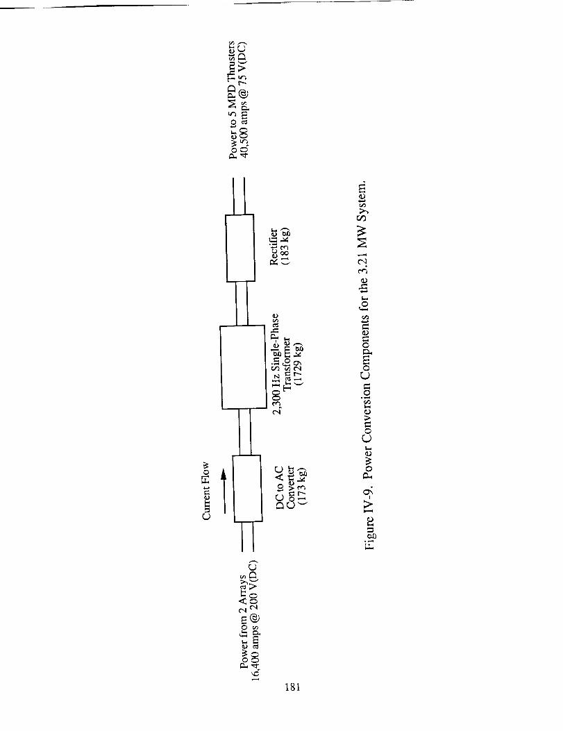
a.®
_E
i _o..r,.) "-"
r..)
¢.1 ¢',1
_E
O_
181
v-,,,,l
t'-,l¢'¢3
o
o
o°_,,I
or..)
o
!
°_,,,
the wires to radiate excess heat at a lower temperature than copper wires, thus, increasing
their efficiency. Power losses through the wires are assumed negligible [6].
AUXILIARY POWER SYSTEMS
The photovoltaic arrays also provide power to the housekeeping equipment,
stationkeeping equipment, and thruster start-up controls. Housekeeping includes
navigation, guidance computers, and thruster management systems. Stationkeeping is
concerned primarily with keeping the arrays properly aligned, through the use of solar
alpha joints and attitude control jets mounted on the array support structure. Thruster start-
up requires a 500 V pulse supplied by a small capacitor bank to be placed across the anode
and cathode. The array is slightly oversized to provide power for housekeeping,
stationkeeping and to compensate for losses in the conversion system.
In the earth's shadow the solar cells are ineffective. Therefore, batteries are
required. As a result of their high mass, however, batteries are only used for housekeeping
purposes and not to power the thrusters. Nickel Hydrogen (NiH2) batteries are used to
provide 100 WH/kg [22]. These batteries are pre-charged when installed at the beginning
of the mission and are recharged as needed by extra power from the arrays. It is expected
that the power necessary for stationkeeping and housekeeping will be small, therefore, the
batteries should add no significant mass to the spacecraft.
182
SPACECRAFT CONFIGURATION AND STRUCTURE
Tad A. Unger
The three main structural components of the MPD propelled vehicle are the solar
array platform, the main body, and the cargo containers. The array platform structure must
rigidly support the array while remaining lightweight. The main body, attached to the array
platforms' main masts, serves to hold the thrusters, propellant tanks, guidance systems,
power conditioning equipment and the payload assembly.
The preliminary analysis uses beam theory to approximate the characteristics of the
trusses as beams so that stress components and, ultimately, truss element dimensions can
be determined. The natural frequency of the structure is estimated by Rayleigh's method.
More accurate and detailed analyses could be carried out using a finite element approach;
however, the objective of this analysis is to give a general idea of the masses involved.
Generation of a structural model for every proposed configuration would have been too
time consuming. Accordingly, there is much optimization left for future studies.
CONFIGURATION OF THE SOLAR ARRAY
The solar cell array structure consists of two platforms, each extending to either
side of the vehicle's main body. A series of tetrahedral trusses are attached to a box-truss
main mast to form a square platform, as shown in Fig. IV-10. The tetrahedral truss
arrangement of the platform is chosen since it uses fewer elements per cell, as compared to
a box truss system, while supporting the same area. The term "cell" refers to the smallest
section of a truss which has a square base on which to rest the solar cells, i.e. two
tetrahedrons or one box.
The box truss is chosen for the main mast since a square has a greater stiffness than
a triangle for the same depth. The box truss also provides a flat side to which the roots of
the tetrahedral trusses can be attached.
183
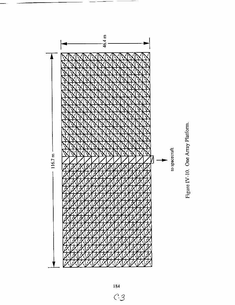
_11_ %1¢
%11 %11
%Pk %Pk
//,w &
lij_ ,iJl'
_' IJl'
t, :
r! r!
#ii 111
??
.I "
%1 •
_V',,%11 _ I
//&&
,i. ,t_
,t, ,_
I._ ' I_ '
/_,I_ #1.1
F ! F !
??
_ _ | ..
- | .
_ _ _ i _
= : _- =
! *
: : : | .
1111/
,_,.,. ,,..,.
,_. ,I. ,_ ,_ ,),_
,t, ,_ ,_ ,. ,).,,
,t_ ,i_ ,i_ ,,_ ,i_,
: : , ._ , : " =
#lJI I_JI Ill #lJI
I._ _ I_1 I._ _1 _,! ,! v! v! .
l'Jl l'J l_J I'_ llJ_
v_. ,! F! .! .
,??;)?Y,
).(
e:)m
<0
©
),===(
ObI==.
c,O
L_
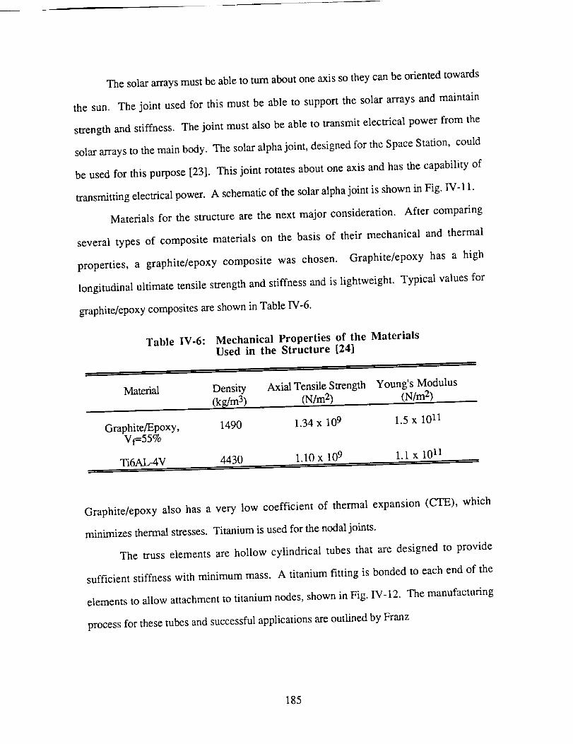
The solar arrays must be able to turn about one axis so they can be oriented towards
the sun. The joint used for this must be able to support the solar arrays and maintain
strength and stiffness. The joint must also be able to transmit electrical power from the
solar arrays to the main body. The solar alpha joint, designed for the Space Station, could
be used for this purpose [23]. This joint rotates about one axis and has the capability of
transmitting electrical power. A schematic of the solar alpha joint is shown in Fig. IV- 11.
Materials for the structure are the next major consideration. After comparing
several types of composite materials on the basis of their mechanical and thermal
properties, a graphite/epoxy composite was chosen. Graphite/epoxy has a high
longitudinal ultimate tensile strength and stiffness and is lightweight. Typical values for
graphite/epoxy composites are shown in Table IV-6.
Table IV-6: Mechanical Properties of the MaterialsUsed in the Structure [24]
Material Density
(k_/m 3)
Axial Tensile Strength Young's Modulus
(N/m 2) (N/m 2)
Graphite/Epoxy, 1490 1.34 x 10⁹ 1.5 x 10¹¹Vf=55%
Ti6AL-4V 4430 1.10 x 10⁹ 1.1 x 10 I1
Graphite/epoxy also has a very low coefficient of thermal expansion (CTE), which
minimizes thermal stresses. Titanium is used for the nodal joints.
The truss elements are hollow cylindrical tubes that are designed to provide
sufficient stiffness with minimum mass. A titanium fitting is bonded to each end of the
elements to allow attachment to titanium nodes, shown in Fig. IV-12. The manufacturing
process for these tubes and successful applications are outlined by Franz
185
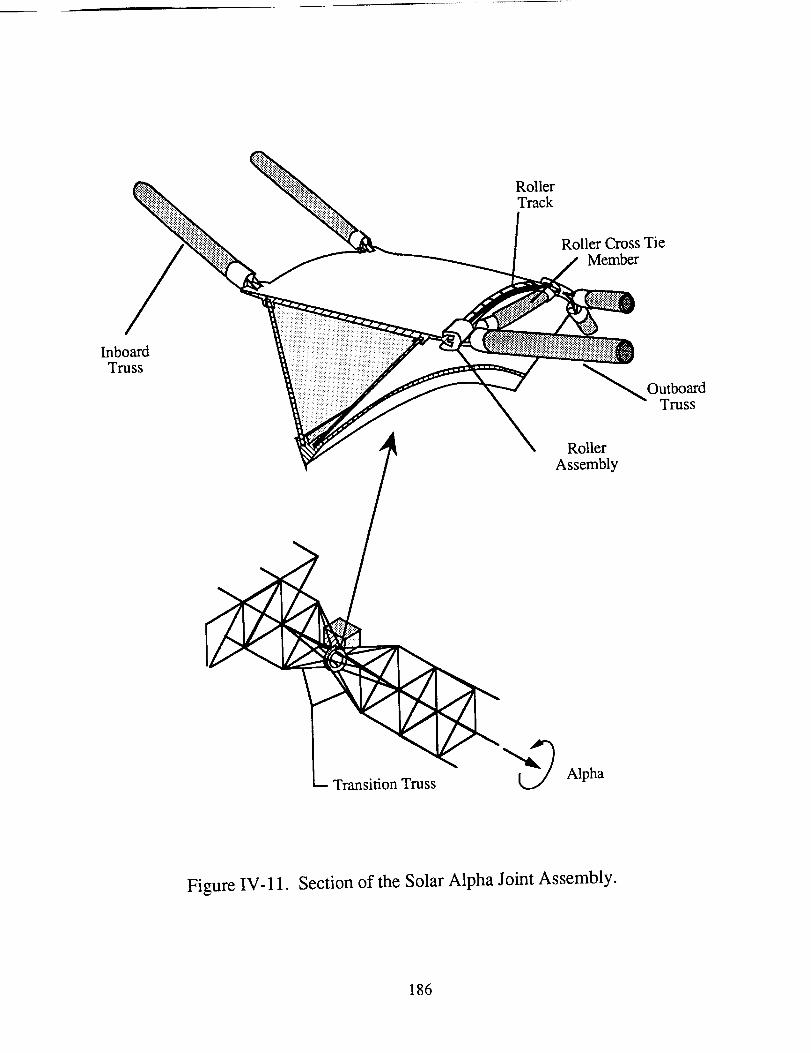
RollerTrack
/Inboard
Truss
Roller Cross TieMember
Roller
Assembly
_ Transition Truss _ Alpha
Figure IV-11. Section of the Solar Alpha Joint Assembly.
186
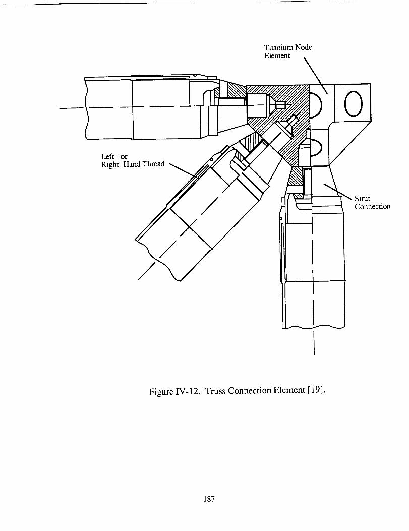
TitaniumNodeElement
Left - orRight-HandThread
0
Strut
Connection
// I
Figure IV-12. Truss Connection Element [19].
187
andLaube[25]. Both the endfitting and thenodearethreadedto allow the elementto
"turnbuckle"intoplace(FigureIV-12), providinga simpleway to achievegoodalignment
andeasyassembly.
STATIC AND DYNAMIC ANALYSIS OF THE ARRAY STRUCTURE
The mast and the platform are made up of truss beams. Beam theory is used to
determine displacements and stresses in the longitudinal elements where the stresses are
greatest. Beam theory provides the simplest way to estimate element dimensions such as
cell size, element diameter, and wall thickness. The maximum stress of the root elements
determines the minimum tube size.
The loads on the solar array structure come primarily from inertia and drag. The
inertial loads are created by accelerating the structure supporting the solar arrays, the wires
for power transfer, and the solar cells themselves.
Drag is a function of density, frontal area, velocity, and a characteristic coefficient
of drag associated with a particular design shape. Since the largest density that the
spacecraft will encounter occurs in Low Earth Orbit, the drag in this orbit needs to be
examined. The atmospheric density in LEO (equivalent altitude of 500 km) is
approximately 10 "13 kg/m 3. The velocity of the ship at this altitude is roughly 7.6 km/s.
The drag coefficient for a flat plate, in the worst case when the arrays are perpendicular to
the direction of travel, is 4 from free molecular flow theory [26]. Table IV-7 shows the
drag on the vehicle for a variety of array areas.
188
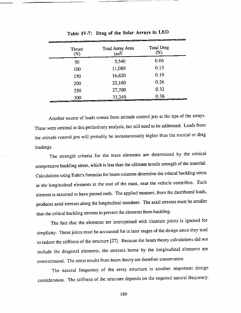
Table IV-7: Drag of the Solar Arrays in LEO
Thrust Total Array Area Total Drag
(N) (m 2) (N)
50 5,540 0.06
100 11,080 0.13
150 16,620 0.19
200 22,160 0.26
250 27,700 0.32
300 33,240 0.38
Another source of loads comes from attitude control jets at the tips of the arrays.
These were omitted in this preliminary analysis, but still need to be addressed. Loads from
the attitude control jets will probably be instantaneously higher than the inertial or drag
loadings.
The strength criteria for the truss elements are determined by the critical
compressive buckling stress, which is less than the ultimate tensile strength of the material.
Calculations using Euler's formulas for beam columns determine the critical buckling stress
in the longitudinal elements at the root of the mast, near the vehicle centerline. Each
element is assumed to have pinned ends. The applied moment, from the distributed loads,
produces axial stresses along the longitudinal members. The axial stresses must be smaller
than the critical buckling stresses to prevent the elements from buckling.
The fact that the elements are interspersed with titanium joints is ignored for
simplicity. These joints must be accounted for in later stages of the design since they tend
to reduce the stiffness of the structure [27]. Because the beam theory calculations did not
include the diagonal elements, the stresses borne by the longitudinal elements are
overestimated. The stress results from beam theory are therefore conservative.
The natural frequency of the array structure is another important design
consideration. The stiffness of the structure depends on the required natural frequency.
189
Theminimum allowablefrequencyis roughly 1Hz, avaluecomparablewith thenatural
frequencyof thespacestationstructure[28]. Belowthis frequency,maintainingcontrolof
thestructurebecomesdifficult.
The structure'snatural frequencymust not coincide with the frequencyof any
varying applied loads such as a pulsed thrusteror the cyclic thermal expansionand
contractionof thestructure.SincetheMPD thrustersfor thismissionaresteady-state,they
donot createanoscillatoryforce. Also, sincethearraydoesnotrotatewith respectto the
sun,cyclesof thermalexpansionandcontractionariseonly from enteringandleavingthe
Earth'sshadow. This frequencyis too low to couplewith the natural frequencyof the
structure.
Themostimportantpartof thearraystructure,dynamicallyspeaking,is thebending
of themast.ThenaturalfrequencydependsinverselyonL3/'2,whereL is thedistancefrom
thespacecraftcenterlineto thetip of oneof thearrays.Themast'slowestnaturalfrequency
isestimatedusingRayleigh'smethodasoutlinedin AppendixC. Thefrequenciesfor each
of thethrustconditionsarepresentedin TableIV-8.
The dimensionsof the tubeelementsfor the structurespecifiedby the natural
frequencyrequirementresult in sucha high critical compressivebuckling load for the
elementsthatit becomesunnecessaryto worry aboutanystrengthcriteria. Essentially,the
tubesize,andthereforethe structuremass,is setby the dynamics. The trusselement
tubesvary in diameterfrom 5 cm for thesmallerarraysto 30cm for thelargestarray. The
tubewall thicknessalsovariesaccordingto whereit is used,thethickertubesin themast
andthinnertubesin theplatform. Forthe100N thrustconditionthemasttubesare5cm in
diameterandhavea wall thicknessof 6 mm. The mastcells arecubes9.3 m on a side.
The tubesusedin the platform arealso5 cm in diameterand havea wall thicknessof
2 mm. Theplatformcellsare8.14m long and9.3m deep.
190
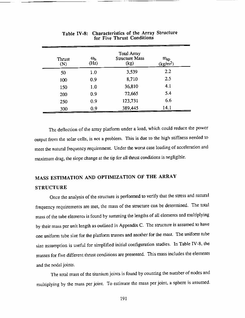
Table IV-8: Characteristics of the Array Structurefor Five Thrust Conditions
Total Array
Thrust COn Smacture Mass msp
(N) (Hz) (kg) (kg/m 2)
50 1.0 3,539 2.2
100 0.9 8,710 2.5
150 1.0 36,810 4.1
200 0.9 72,665 5.4
250 0.9 123,731 6.6
300 0.9 389,445 14.1
The deflection of the array platform under a load, which could reduce the power
output from the solar cells, is not a problem. This is due to the high stiffness needed to
meet the natural frequency requirement. Under the worst case loading of acceleration and
maximum drag, the slope change at the tip for all thrust conditions is negligible.
MASS ESTIMATION AND OPTIMIZATION OF THE ARRAY
STRUCTURE
Once the analysis of the structure is performed to verify that the stress and natural
frequency requirements are met, the mass of the structure can be determined. The total
mass of the tube elements is found by summing the lengths of all elements and multiplying
by their mass per unit length as outlined in Appendix C. The structure is assumed to have
one uniform tube size for the platform trusses and another for the mast. The uniform tube
size assumption is useful for simplified initial configuration studies. In Table IV-8, the
masses for five different thrust conditions are presented. This mass includes the elements
and the nodal joints.
The total mass of the titanium joints is found by counting the number of nodes and
multiplying by the mass per joint. To estimate the mass per joint, a sphere is assumed.
191
For element attachment, 14 holes, equally spaced over the surface, are bored. The mass of
one of these joints is then just the volume times the density.
The specific mass (msp) of the array structure shown in Table IV-8 is the amount of
mass supported by the array structure per unit area, which includes the mass of the
structure, solar cells, and wires. The specific mass for current solar array structures is
about 1.7 to 2 kg/m 2 [28]. The specific masses presented in Table IV-8 are much higher
than this for the larger structures. This is due mostly to the arcing between solar cells on
the array, which makes larger and more wires necessary. For the 100 N thrust condition
the wire mass is 43% of the total array. As the power level increases, this figure rises.
Further optimization can reduce the structure mass by more efficient utilization of trusses,
such as reducing the element mass per unit length as stresses are reduced along the length.
Figure IV-13 indicates that the total mass of the structure, for constant element
diameter and thickness, decreases with an increase in element length, or cell size.
However, the critical buckling stress decreases with the square of the element length. It
was found that stiffening the element by increasing the wall thickness, rather than shrinking
the cell size, is more effective per unit mass of the structure as a whole.
With larger cell sizes, it is possible that the solar ceils may not be able to support
themselves under a load, such as drag. If this is the case, the truss cell size can be reduced.
Since cell size has an extreme effect on the overall mass, it may prove beneficial to attach
the solar cells to a stiffening mesh backing strong enough to support the loading, then
attach the mesh to the truss.
MAIN BODY STRUCTURE
Figure IV-14 shows the main body configuration. The components of the main
body include the primary container, two secondary containers, and the structure to hold the
propellant tank. The main body is made up of box trusses.
192
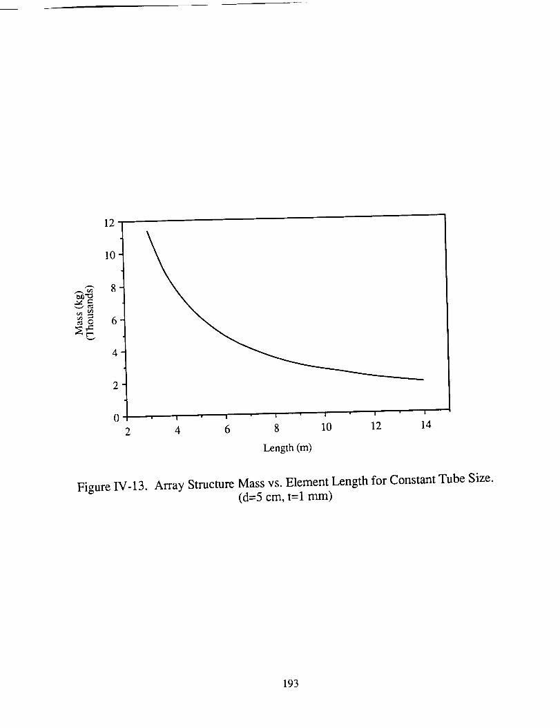
12
10
"-" 8
_o 6
4
2
0
2 4 6 8 10 12 14
Length (m)
Figure IV-13. Array Structure Mass vs. Element Length for Constant Tube Size.(d=5 cm, t= 1 mm)
193

To ArrayPlatform
rrrrrr_
Propellant tank "_"------ Solar Alpha Joint
_ _ _.......- Secondary container
-- !i'i!i'ii_l!i" , _ Thrusters
!_ !_ Primary container
Payload AssemblyAttaches Here
I I10m
o Array Platform
Figure IV-14. Main Body Structure Arrangement.
194
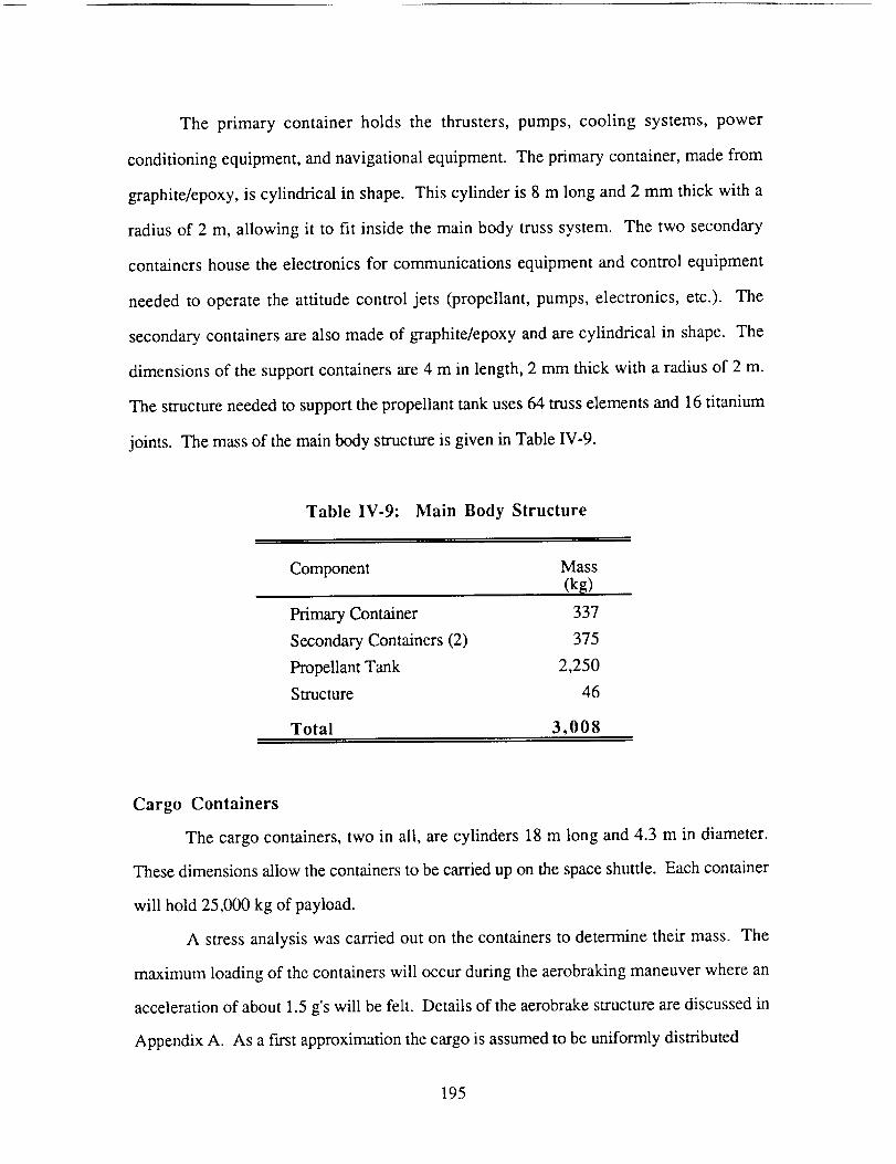
The primary container holds the thrusters, pumps, cooling systems,power
conditioningequipment,andnavigationalequipment.Theprimary container,madefrom
graphite/epoxy,is cylindrical in shape.This cylinder is 8 m longand2 mm thick with a
radiusof 2 m, allowing it to fit inside themain body trusssystem. The two secondary
containershousetheelectronicsfor communications equipment and control equipment
needed to operate the attitude control jets (propellant, pumps, electronics, etc.). The
secondary containers are also made of graphite/epoxy and are cylindrical in shape. The
dimensions of the support containers are 4 m in length, 2 mm thick with a radius of 2 m.
The structure needed to support the propellant tank uses 64 truss elements and 16 titanium
joints. The mass of the main body structure is given in Table IV-9.
Table IV-9: Main Body Structure
Component Mass(k_)
Primary Container 337
Secondary Containers (2) 375
Propellant Tank 2,250
Structure 46
Total 3,008
Cargo Containers
The cargo containers, two in all, are cylinders 18 m long and 4.3 m in diameter.
These dimensions allow the containers to be carried up on the space shuttle. Each container
will hold 25,000 kg of payload.
A stress analysis was carried out on the containers to determine their mass. The
maximum loading of the containers will occur during the aerobraking maneuver where an
acceleration of about 1.5 g's will be felt. Details of the aerobrake structure are discussed in
Appendix A. As a first approximation the cargo is assumed to be uniformly distributed
195
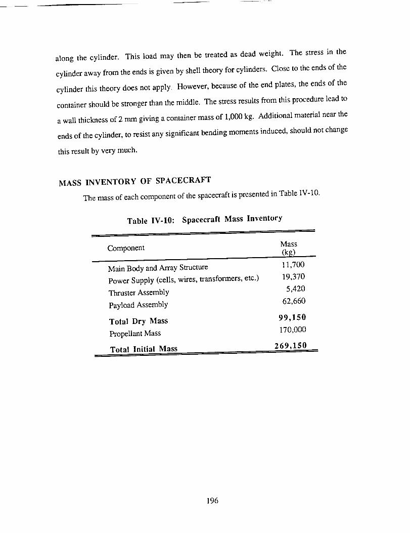
along the cylinder. This load may then be treatedasdeadweight. The stressin the
cylinderawayfrom theendsisgivenby shelltheoryfor cylinders.Closeto theendsof the
cylinder this theorydoesnot apply. However,becauseof the endplates,theendsof the
containershouldbestrongerthanthemiddle. Thestressresultsfrom thisprocedureleadto
awall thicknessof 2 mmgivingacontainermassof 1,000kg. Additional materialnearthe
endsof thecylinder,to resistanysignificantbendingmomentsinduced,shouldnotchange
thisresultby verymuch.
MASS INVENTORY OF SPACECRAFT
Themassof each component of the spacecraft is presented in Table IV-10.
Table IV-IO: Spacecraft Mass Inventory
Component
Main Body and Array Structure
Power Supply (cells, wires, transformers, etc.)
Thruster Assembly
Payload Assembly
Total Dry Mass
Propellant Mass
Total Initial Mass
Mass
(kg)
11,700
19,370
5,420
62,660
99,150
170,000
269,150
196
ORBITAL MECHANICS
Jacqueline Auzias de TurenneBarbrina Dunmire
The solar-powered MPD propelled spacecraft begins its mission from an initial low
Earth orbit (LEO), 500 km above the surface of the Earth and aligned with the ecliptic
plane. As opposed to the SRA powered spacecraft and the SPL powered spacecraft,
however, the MPD powered spacecraft does not return to the Earth. Instead, the spacecraft
remains in a high Mars orbit providing an orbiting control center for the subsequent
manned Mars missions. The one-way transfer of the MPD propelled spacecraft from LEO
to Mars can be separated into three phases:
(1) Earth Escape
(2) Earth-to-Mars Transfer
(3) Mars Encounter
Due to the low thrust nature of the MPD propelled spacecraft, impulsive orbital
maneuvers such as a Hohmann transfer, or similar elliptical transfers which intersect the
orbit of Mars and require a minimum hyperbolic excess speed at Earth orbit of 3 km/sec,
which cannot be performed. The patched conic technique was used to approximate an
orbital trajectory from the Earth to Mars. The patched conic approximation defines distinct
spheres of influence about each gravitational body, allowing the sequential solution of the
two body problem [28]. The interplanetary trajectory of the MPD propelled spacecraft is
depicted in Fig. IV- 15.
It should also be noted that throughout this orbital analysis, the following
assumptions were made:
197
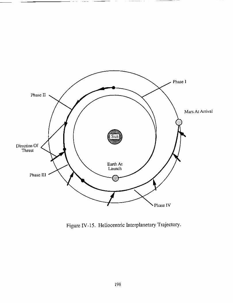
PhaseI
PhaseII
MarsAt Arrival
DirectionOfThrust
PhaseIII
EarthAtLaunch
PhaseIV
Figure IV-15. Heliocentric Interplanetary Trajectory.
198
(1)
(2)
(3)
At anytimeduringthetransfer,thespacecraftisunderthe influenceof only
onegravitationalbody.
The spacecraftoperatesin the absenceof aerodynamicdrag. The drag
effects felt by the spacecraftneartheEarth arenegligible, asdetermined
earlier.
Theorbitsof boththeEarthandMarsarecircularandcoplanar.
Thefollowing analysisis apreliminaryexaminationof theorbitalmechanicsfor this
solar-poweredMPD propelledvehicle. It shouldbenotedthatthepatchedconic analysis
presentedhereindicatesone possible orbital trajectory of an MPD propelled spacecraft
designed for Mars missions. The basic elements of this interplanetary transfer to Mars are
described. Further research will be required to determine a more optimum interplanetary
transfer.
EARTH ESCAPE
The MPD propelled spacecraft uses a spiral transfer orbit to escape the Earth's
gravitational field, as shown in Fig. IV-16. Spiral maneuvers allow for slower energy
gains, which can be supplied by the low thrust MPD thrusters. The equations governing
the motion of the spacecraft [29] are shown below:
"r' Fcoset re)2 + r_2 + Fsine= mtv - g°(T- mt (IV-9)
where
= Fcos0+ 2/'+mtv r (IV-10)
v + (IV-11)
199
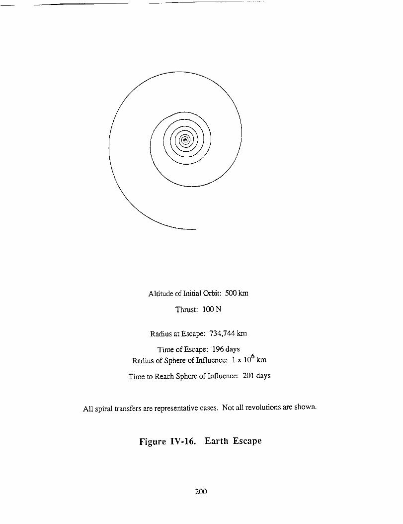
Altitudeof Initial Orbit: 500krn
Thrust: 100N
RadiusatEscape:734,744krn
Timeof Escape:196daysRadiusof Sphereof Influence: 1x 10⁶km
Timeto ReachSphereof Influence:201days
All spiraltransfersarerepresentativecases.Not all revolutionsareshown.
Figure IV-16. Earth Escape
200
Theequationsof motiondefinetheradialposition, r, of the spacecraft measured from the
center of the Earth and the angular position, q0, of the spacecraft measured from its initial
position. The thrust from the MPD thrusters and the instantaneous mass of the vehicle are
represented by F and M t, respectively, while the gravitational acceleration at the surface of
the Earth is indicated by go and the radius of the Earth is indicated by r e.
A fourth-order Runge-Kutta integration of the equations of motion was used to
determine the characteristics of the spiral trajectory [30]. The integration was carried out
over arbitrary intervals of 500 seconds, or 8.33 minutes. Smaller time intervals resulted in
increased computational time without any significant increase in accuracy.
The MPD propelled spacecraft begins the spiral transfer solely under the
gravitational influence of the Earth. The spacecraft uses constant, tangential thrust
throughout the maneuver. Upon achieving the local escape velocity, the spacecraft ceases
its spiral trajectory and enters a parabolic orbit. The local escape speed, Yesc, is determined
from the equation below:
The escape speed is defined in the reference frame of the Earth and depends on the
gravitational parameter of the Earth, ge' and the radial distance from the center of the Earth
to the spacecraft, r.
The computer program used to perform the Runge-Kutta integration, designated
SPIRAL, appears in Appendix D. Using SPIRAL, the time required to reach the point of
departure and the altitude at the point of departure were determined for various thrust levels
of the MPD thrusters and the corresponding spacecraft configurations. Since the MPD
propulsion system operates only when solar energy is available, SPIRAL accounts for a
coast phase during each revolution about the Earth as the spacecraft travels through the
Earth's shadow.
201
The timeresultsfrom SPIRALareshownin Fig. W-17. Since the spiral maneuver
is a constant thrust maneuver, the time duration of the spiral transfer also indicates the
corresponding thruster burn time. Vehicles operating at higher thrust levels are able to
complete spiral maneuvers faster and have lower thruster burn times than vehicles operating
at lower thrust levels. At thrust levels above approximately 100 N, however, the
increasing total mass of the spacecraft becomes the dominant factor and increases in thrust
can no longer accommodate the corresponding increases in total vehicle mass.
Consequently a minimum thruster burn time required to reach escape speed occurs at the
100 N level. The minimum thruster burn time eliminates the need to carry and configure an
excess of thrusters as well as the associated solar array and structural components. The
radius at escape for a spacecraft providing 100 N of thrust is approximately 7.3 x 10⁵ km.
The characteristic velocity change, Av, for the spiral transfer is determined from the
equation below:
Av= ueln(_-f) (W-13)
The Av of a mission is a measure of the energy input to the spacecraft and depends on the
exhaust velocity of the thrusters, u e, and the initial and final masses of the spacecraft, m o
and mf, respectively. Low thrust missions in the near vicinity of a gravitational body
experience large gravity losses. Consequently, more energy is needed to perform orbital
maneuvers, and the characteristic Av for the transfer is increased. The Av value required to
reach escape speed at the 100 N thrust level was 7.3 km/sec.
EARTH-TO-MARS TRANSFER
When the spacecraft attains the escape velocity, it has not yet departed the Earth's
sphere of influence. At the 100 N thrust level, the radius at escape is 7.3 x 10⁵ km, as
stated earlier, while the sphere of influence of the Earth is approximately 106 km.
202

90
85
8O
75
70
65
60
55
5O
50 70 90 110 130 150 170 190 210 230
Thrust - at Earth (N)
250
Figure IV-17. Thruster Bum Time Dependency on Thrust.
203
Therefore, the spacecraft remains under the effect of the Earth's gravitational influence.
Maintaining a constant tangential thrust of 100 N, the spacecraft achieves a velocity of
approximately 30.8 krn/sec, with respect to the sun, at the edge of the sphere of influence,
as determined through SPIRAL.
Upon escape from the Earth's sphere of influence, the MPD propelled spacecraft
begins to experience the gravitational effects of the sun. All geocentric coordinates are
converted to a heliocentric coordinate system [31 ]. The spacecraft coasts, accelerates, and
then decelerates as it travels en route to Mars [33,34]. Throughout the heliocentric transfer,
the MPD propelled spacecraft accounts for the diminishing thrust available as the distance
from the sun increases, as shown in Fig. IV-4. All orbital calculations during the
heliocentric transfer were performed through a computer program, HELIOCENTRIC,
which also uses a Runge-Kutta integration to numerically solve the equations of motion of
the spacecraft about the sun. HELIOCENTRIC appears in Appendix D.
The desired Earth-to-Mars transfer orbit requires a minimum radial velocity
approaching Mars in order to reduce the amount thrust required to enter a Mars parking
orbit. The heliocentric interplanetary transfer is shown in Figure IV-15. The radius and
thrust angle, along with the thrust at each radius, the time spent at each radial stage of the
heliocentric transfer, and a nominal phase reference, are listed in Table IV- 11.
During Phase I of the heliocentric transfer, the spacecraft coasts in order to decrease
the velocity of the spacecraft through a reduction of the radial velocity component. Without
further application of thrust, however, the spacecraft would return to the Earth's Orbit
along an elliptical path after reaching a radius of 1.8 x 10⁸ km. Therefore, during Phase II,
a tangential thrust of 60 N is applied in order to maintain the outbound trajectory toward the
Martian Orbit. Although 80 N of thrust is available during Phase II, only a 60 N tangential
thrust is required to produce a sufficient velocity increase.
In Phase III, 80 N of thrust is applied at a thrust angle of -110 ° to again begin
decreasing the radial component of velocity. Finally, during Phase IV of the heliocentric
204
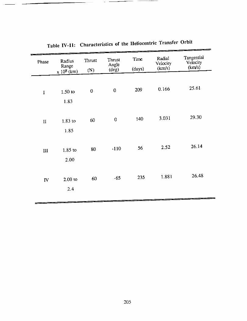
Table IV-11: Characteristics of the Heliocentric Transfer Orbit
Phase Radius Thrust Thrust Time Radial TangentialRange Angle Velocity Velocity
x 108 (km) (N) (deg) (days) (km/s) (km/s)
1.50 to
1.83
0 0 209 0.166 25.61
II 1.83 to
1.85
60 0 140 3.031 29.30
111 1.85 to
2.00
80 -110 56 2.52 26.14
IV 2.00 to
2.4
60 -65 235 1.881 26.48
205
transferorbit, 60 N of thrust is applied at a thrust angle of -65 ° to further decrease the
radial component of velocity, and to reduce the tangential velocity, on the spacecraft's final
approach to the Martian orbit. The final velocity upon approach to the orbit of Mars is
approximately 26.5 km/sec and corresponds to an angle of 3 ° between the orbit of Mars
and the flightpath of the spacecraft. The approach velocity relative to Mars is
approximately 2.41 km/sec. The total time of the Earth-to-Mars transfer, excluding any
time spent performing spiral maneuvers at either the Earth or Mars, is approximately
640 days, or 1.75 years.
MARS ENCOUNTER
The Mars encounter consists of maneuvers by the MPD propelled spacecraft to
deliver its payload into a low Mars parking orbit, while the mother spacecraft enters into a
high Mars parking orbit and becomes an orbiting control station for ensuing manned Mars
missions. The payload's aerobrake maneuver is discussed in detail in Appendix A. The
altitude of the low Mars parking orbit was selected arbitrarily through a density analysis of
the Martian atmosphere to be 300 km above the planet's surface [32]. At an altitude of
300 km, the density of the Martian atmosphere is equal the density of the Earth's
atmosphere at an altitude of 500 km, thereby determining the equivalent to LEO at Mars.
The altitude of the high Mars parking orbit is designated, also arbitrarily, to be 4600 km.
After releasing the payload assembly, the mother spacecraft proceeds to follow a
spiral descent into the high Mars parking orbit, as shown in Fig. IV-18. At Mars, a
maximum thrust of 40 N is applied tangentially throughout the spiral maneuver. The
characteristics of the Martian spiral descent were determined through a modified version of
SPIRAL, MSPIRAL, specific to Mars. MSPIRAL appears in Appendix D. The spacecraft
required 33 days to perform this maneuver. The total flight time from LEO to the high
Mars orbit is 873 days or 2.39 years.
206
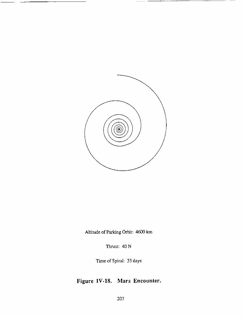
Altitudeof ParkingOrbit: 4600km
Thrust: 40N
Timeof Spiral: 33days
Figure IV-18. Mars Encounter.
207
CONCLUSION
Jacqueline Auzias de Turenne
This section of the report has presented a feasibility study of an MPD propelled
spacecraft for use as a cargo ferry to deliver a 50,000 kg payload to Mars. The MPD
propulsion system ionizes the incoming gaseous argon propellant and uses electromagnetic
forces to accelerate the resulting plasma to a high exhaust velocity. The thrusters are low
thrust devices (20 N each) with a 2000 hour lifetime per cluster. A multiple thruster
configuration, consisting of 43 thrusters, allows a cluster of five units at a time to be fined
for the lifetime of the thruster set before an alternative set of thrusters is fired. Argon
appears to be a promising propellant as a result of its high density, high liquefaction
temperature, and low vaporization energy. The argon is stored in an ellipsoidal fuel tank,
with a volume of 78 m 3.
The power to operate the thrusters comes from two indium phosphide solar arrays.
Indium phosphide solar cells are expected to achieve efficiencies of 21%, along with an
increased production rate, within the next 20 years. The degradation incurred from the Van
Alien radiation belts is eliminated through the process of self-annealing. Self-annealing
passes current from operational solar cells through forward biased diodes within degraded
cells to maintain a maximum efficiency for the duration of the mission. The power from
the solar arrays is conditioned through a constant voltage transformer and an inverter prior
to use in the MPD thrusters.
The support structure for the MPD propelled spacecraft is composed of
graphite/epoxy truss elements interconnected with titanium joints. Graphite/epoxy
minimizes structural mass while providing maximum rigidity for the spacecraft. A key
structural element is the solar alpha joint, which allows the solar arrays to rotate about one
axis while transmitting electrical power from the solar arrays to the power conditioning
components within the main body of the spacecraft.
208
The orbital mechanicsof theMPD propelledspacecraftwasdeterminedthrough
patchedconic approximations.The spacecraftfollows a spiral trajectory to escapethe
gravitational influence of the Earth, and entersa heliocentric transfer to Mars, which
consistsof a coast phase,an accelerationphase,and a decelerationphase. As the
spacecraft approaches Mars, the payload assembly is jettisoned to follow an aerobrake
maneuver into a low Mars parking orbit. The mother spacecraft uses a spiral maneuver to
enter a high Mars parking orbit, where it remains as an orbiting control station. The total
flight time required for the spacecraft to reach Mars is approximately 873 days, or 2.39
years while the total vehicle mass is 269,150 kg, indicating a payload mass ratio of 19%.
Refinements in the orbital transfer of the spacecraft are expected to reduce the
required thruster burn time, and thus propellant consumption, consequently increasing the
payload capacity (mass ratio). Nevertheless, an MPD propelled spacecraft is a viable
option for deep space travel.
209

NOMENCLATURE
A
b
BOL
B@
%CTE
d
e
Evap
F
f_
fz
go
Is
Jr
Jz
J
k
L
LEO
m
15
M
MLI
MPD
surface area
constant of proportionality
beginning of life
azimuthal magnetic field
specific heat
coefficient of thermal expansion
thickness
electron charge
vaporization energy
thrust
electromagnetic pumping force
electromagnetic blowing force
gravitational acceleration at the earth's surface
intensity of the sun
radial arc current
axial arc current
diffuse arc current
conductivity of heat coefficient
distance
low Earth orbit
mass
mass flow rate
molecular mass
multilayer insulation
magnetoplasmadynamic
210

N O
r
T
Tliq
%xt
T1
T2
T3
Ue
v
V
Avogadro's Number
heat flux
heat flux through the MLI to the outer propellant tank wall
heat absorbed by the propellant
radius
temperature
liquid storage temperature
external storage temperature
external surface temperature of the vapor cooled shield
temperature of propellant vapor in the vapor cooled shield
temperature of the exiting propellant liquid
exit velocity
velocity of the ship
potential difference
0_
A
E
rl
B
_to
0
P
O
cp
03 n
absorptivity
change in
emissivity
ionization potential
overall efficiency of the thruster
gravitational parameter
permeability of free space
thrust angle
density
Stephan-Boltzman constant
angular position
natural frequency
211
Subscripts
a anode
c cathode
cr critical value
e Earth
esc escape
f final state
liq liquid
o initial state
sp specific
t instantaneous value
A dot above a variable ( ) indicates a time derivative.
successive time derivatives.
All values are in MKS units.
Successive dots indicate
212
REFERENCES
1, Cassady, R. J., "An MPD Thruster Driven Cargo Ferry for Support of the Manned
Mars Mission", AIAA/ASME/SAE/ASEE 24th Joint Propulsion Conference, AIAA
Paper No. 88-2896, July, 1988.
, Jahn, R. G., physics of Electric Propulsion, McGraw-Hill Book Co., New York,
1968.
3. Rudolph, L. K. and Pawlick, E. V., "The MPD thruster Development Program",
AIAA Paper No. 79-2050, Oct., 1979.
4 Tahara, H., "A Quasi-Steady MPD Arc Jet for Space Propulsion", 17th
International Electric Propulsion Conference, Tokyo, Japan, May 28-31, 1984.
. Malliaris, A. C., et aI., "Performance of Quasi-Steady MPD Thrusters at High
Powers", AIAA Journal, Vol. 10, 1972.
. King, D. Q. and Sercel, J. C., "A Review of the Multimegawatt MPD Thruster and
Current Mission Applications", AIAA Paper No. 86-1437, June, 1986.
, King, D. Q., et al., "Effect of Thrust Chamber Configuration on MPD Arcjet
Performance", AIAA Paper No. 79-2051, Oct., 1979.
8, Coomes, E. P., et al., "The Pegasus Drive - A Multimegawatt Nuclear Electric
Propulsion System", in Space Nuclear Power Systems, Orbit Book Company,
Malabar, FL, pp. 365-373, 1987.
213
9, Kit, B. and Everud, D., Rocket Propellant Handbook, The Macmillan Co., NY,
1960.
10. Brown, N. S., "Advanced Longterm Cryogenic Storage Systems", Lewis Research
Center Microgravity Fluid Management Symposium, Cleveland, OH, April, 1987.
11. Holman, J. P., Heat Transfer, McGraw-Hill Book Co., New York, 1986.
12. Carney, M. J., "Liquid-Vapor Interface Locations in a Spheroid Container Under
Low Gravity", NASA N86-23854, April, 1986.
13. Eberhardt, R. N., Feste, D. A., and Aydelott, J. C., "Shuttle Compatible
Cryogenic Liquid Storage and Supply Systems", AIAA Paper No. 81-1509, July,
1981.
14. Hess, W. N., The R_diatign Belt and Magnetosphere, Blaisdell Publishing Co.,
New York, 1968.
15. Scott-Monck, J. and Stella, P., "Advanced Photovoltaic Solar Array Design
Assessment", N87-26429, Jet Propulsion Laboratory, Pasadena, CA., May, 1987.
16. Kurland, R. and Stella, P., "Status of Advanced Photovoltaic Solar Array
Program", TRW Space and Technology Group, Redondo Beach, CA. / Jet
Propulsion Laboratory, Pasadena, CA., 1988.
214
17. Brinker, D.J. and Weinberg, I., "Indium PhosphideSolar Cells - Status and
Prospectsfor Use in Space",NASA TM-87315, NASA Lewis ResearchCenter,
Cleveland,OH., 1986.
18. Curtis, H.B., andHart, R.E.,Jr., "Performanceof AIGaAs, GaAs,and InGa.As
Cells After 1 MeV of Electron Irradiation", NASA Lewis ResearchCenter,
Cleveland,OH., 1987.
19. Weinberg, I., NASA Lewis Research Center, Cleveland, OH., Private
Communication,Feb., 1989.
20. Stella, P., Jet PropulsionLaboratory,Pasadena,CA., Private Communication,
Feb., 1989.
21. Calloway, T. M., Leeman,J. E., and Key, T. S., "Comparisonof Designs for
PhotovoltaicPowerConditioners",Sand86-0184,SandiaNational Laboratories,
Albuquerque,NM., 1986.
22. Faymon,K. A., "SpacePowerTechnologyto MeetCivil MissionRequirements",
AA420 GuestLecturer,Universityof Washington,Jan.31, 1989.
23. Mikulas, M. and Bush,H., "Design, Construction,and Utilization of a Space
StationAssembledFrom a 5 MeterErectableTruss",NASA TM-89043, NASA
LangleyResearchCenter,Oct., 1986.
24. Chetty,Satellite Technology and its Applications, Tab Book, Inc., 1988.
215
25. Franz, J. and Laube, H., "Design and Manufactureof Tubular CarbonFiber
Composite/TitaniumBondedJoints", CompositeStructures,Vol. 6, No. 1-3,
pp. 183-196, 1986.
26. Eberhardt, S., Department of Aeronautics and Astronautics, University of
Washington, Private Communication, Feb., 1989.
27. Bush, H. G. and Mikulas, M. M., "Advances in Structural Concepts", NASA CP-
2269 Part 1, NASA Langley Research Center, May 1983.
28. Mikulas, M., NASA Langley Research Center, Private Communication,
March 6, 1989.
29. Bate, R. R., Mueller, D. D., and White, J. E., Fundamentals of Astrodynamics,
Dover Publications, Inc., New York, 1971.
30. Stuhlinger, E., "The Flight Path of an Electrically Propelled Space Ship", Jet
Propulsion, Vol. 27, pp. 410-414, 1957.
31. Paris, S. W., Flight Mechanics Specialist, Boeing Aerospace Co., Seattle, WA,
private communication, March, 1989.
32. Stuhlinger, E., Ion Propulsion for Space Flight, McGraw-Hill Book Company,
New York, 1964.
33. Bruckner, A. P., Research Professor, Department of Aeronautics & Astronautics,
University of Washington, Seattle, WA, private communication, March, 1989.
216

V. CONCLUSION
CONCLUSION
Amy Prochko
Each propulsion system collects and exploits solar energy in very different ways.
The spacecraft designs are unique according to the individual requirements of the
propulsion system. The Solar Radiation Absorber (SRA) system directly concentrates the
solar radiation into two chambers where it is absorbed by alkali metal vapor which transfers
the energy to the primary component of the propellant, hydrogen. The Solar-Pumped
Laser (SPL) system uses concentrated solar energy to pump two 6 MW CO 2 lasers located
on two platforms in sun-synchronous orbit around the Earth. The resultant laser beams are
directed and transmitted to receivers on the spacecraft, which relay them to two thruster
chambers, where the laser beams generate a hydrogen plasma. The Magneto-
plasmadynamic (MPD) system converts solar energy to electricity which is used to ionize
argon and accelerate the resultant plasma by electromagnetic body forces. Specific
impulses vary from 1,000 s for the solar radiation rocket to 2,490 s for the magneto-
plasmadynamic thruster.
The SRA system offers the largest payload mass fraction (37%) and the lowest
initial mass (135,500 kg). The latter is an important parameter because all of the
components, materials and propellant necessary for the Mars cargo mission must originally
be brought up from Earth to LEO. Thus, even with anticipated reductions in the cost of
lifting payloads to LEO, there is a great premium on minimizing the initial mass of the
interplanetary spacecraft. The superior performance of the SRA spacecraft is a direct result
of the ability of its thruster to deliver both a high specific impulse (1000 sec) and a
relatively high thrust (30 times higher than the MPD system). This dual capability reflects
back in a considerable savings in the required amount of propellant, resulting in a low
initial mass and a high payload fraction. The total trip time to Mars (281 days) is relatively
short. Furthermore, the SRA spacecraft can be used in a novel "slingshot" orbital
218
maneuverwhich sendsonly thepayloadsystemto Marsandreturnsthe mothercraft to
LEO only 23daysafterlaunch,whereuponit canbereusedfor othermissions. Clearly,
suchfavorableperformanceinvitesmorecomprehensiveinvestigationof this propulsion
concept.
TheSRAsystempresentsanumberof importanttechnologicalproblems,however.
Althoughexperimentalproofof concepthasbeendemonstrated,muchwork remainsto be
doneon thephysicsof theinteractionof solarenergywith thealkali seededhydrogen,on
the handlingof the high temperature,corrosivepotassium,on the designof a suitable
window,andon theproblemsof heattransferanderosionin thethrustchamber.Research
in theseareasis currentlyunderwayattheUniversityof Washington.
The SPL systemhasan initial massof nearly 205,000kg and a payload mass
fractionof 24%,which renderit lessdesirablethantheSRAsystem. However,themost
seriousshortcomingof theSPLsystemis thatit requiresacomplexinfrastructureof space-
basedlasersandrelay satellites,aswell asextremelystringenttrackingcapabilities. The
lattercouldbeamelioratedby usinganorbitalmechanicsscenariosimilarto thatof theSRA
system. Many additionalproblemsalsoneedto be resolvedbeforethe laserpropulsion
conceptcanbe implemented. The requiredCW laserpower levels have not yet been
attainedonEarth. Additionalresearchis neededin theareasof plasmastability,reradiation
losses,and cooling requirements. Even for an optimal orbital transfer scenario,the
complexityandcostof theentiresystemis likely to makeit impractical.
TheMPD propulsionsystemappearsto bethemosttechnologicallyfeasibleat this
time; however,its implementationis predicatedon the availability of indium phosphide
photovoltaiccellsof 21%efficiency. Evenso,its payloadmassfraction (19%)appearsto
be only marginally better than that which might be achievedusing a Shuttle-derived
chemicalpropulsionsystem,andits inital mass,nearly270,000kg, is thehighestof the
threespacecraftpresentedhere. In addition,theMPD spacecraftrequiresthe longesttrip
time,2.39years,andmustremainin Marsorbit,preventingits reusefor subsequentcargo
219
missions. Clearly, considerablework remainsto bedoneto enhancethe payloadmass
fractionandreducetheinitial massof thesolar-MPDsystem,to decreaseits trip time, and
to permitrecoveryof thespacecraftfor reusein futuremissions.
The propulsionconceptspresentedhereusethemost abundantsourceof energy
availablein space:thesun. However,muchfurtherresearchis requiredif this resourceis
to beeffectivelyexploitedto transportlargepayloadsto Marsandotherplanetswithin the
solarsystem.
220

VI. APPENDICES
APPENDIX A
Aerobraking at Mars
Shawn McCrackenMike Rhodes
Since cargo missions to Mars require vehicles of considerable size, containing large
amounts of propellant, missions become very expensive. Therefore, this report has
presented alternative high performance propulsion methods which use solar energy. The
three vehicle concepts in this report release the payload outside the sphere of Mars. Large
amounts of propellant would also be required to impulsively decelerate the payload with
chemical thrusting into low Mars orbit (LMO). Because of this, efforts have been made to
consider an alternative orbital maneuvering approach. Recent advances in technology have
made it possible to design an aeroassisted transfer vehicle (ATV) which uses the
atmosphere of Mars to decelerate the vehicle through its drag and lift, in order to maneuver
into an elliptical orbit with the apogee extending beyond the atmosphere. A small burn is
then required to circularize into the desired parking orbit. The ATV thus reduces the
amount of propellant required for the mission and increases the payload capacity of the
spacecraft by eliminating the propellant necessary for a retro-burn to decelerate the vehicle
from a hyperbolic orbit. Only propellant to circularize from an elliptical orbit is thus
required. Accounting for the thermal shield mass, aerobraking results in a lower overall
system mass, and thus, more efficiently decelerates the vehicle than thrusting for impulsive
maneuvers [1,2]. As a result, aerobraking was chosen for capture into LMO for all three
designs in this report. Discussions on the vehicle design, flight path, stability and control,
flow impingement, heat transfer, shielding materials, and component masses follow.
222
Aerobrake Vehicle Design
Many vehicle designs have been studied for Mars missions. The ATV with a
raked-off sphere cone aeroshell, shown in Fig. A-l, is the best design for aerocapture
missions where landing the vehicle is not required [3]. This aeroshell design consists of a
spherical nose with a radius of 4m and a circular cone after-body raked-off 62 ° from the
cone axis. The aeroshell shields the cargo while it provides lift and drag to decelerate and
maneuver the ATV into the desired orbit. With this design, the overall dimensions of the
vehicle are 25 m for the frustum diameter (major axis) and 16.5 m for the minor axis
diameter.
In the raked-off sphere cone configuration, the cargo is located behind the shield
with its center of mass on the line of force that represents the lift and drag of the vehicle.
Around the cargo, propellant containers for circularizing the orbit and for trajectory
adjustments outside of the atmosphere are located symmetrically around this line of force.
Two tanks for liquid oxygen are located in front and behind the payload, and two liquid
hydrogen tanks are located on each side of the payload. The propellant acquisition uses
surface tension to draw out the liquid. This acquisition system is the same as the ones used
in the solar thermal and laser propulsion designs discussed in the main report. Multilayer
insulation and a vapor shield venting system, both of which will be discussed further in the
component massses section, are used for thermal protection.
Two rockets are positioned forward of the cargo and are used to circularize the orbit
at the apogee. At the apogee, hatch doors in the shield similar to the landing gear doors
used on the Space Shuttle will open in the shield, allowing the telescopic rocket nozzles to
extend out and provide thrust [4]. In the event of a rocket failure, a small amount of
oxygen may be shifted so this rocket configuration does not produce a moment on the
vehicle during the circularizing bum.
223
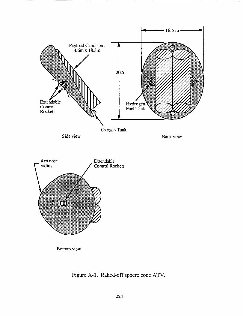
16.5m _"-i
PayloadCannisters !.5
E IIIIII
Oxygen Tank
Side view Back view
4 m nose Extendableradius Control Rockets
Bottom view
Figure A-1. Raked-off sphere cone ATV.
224
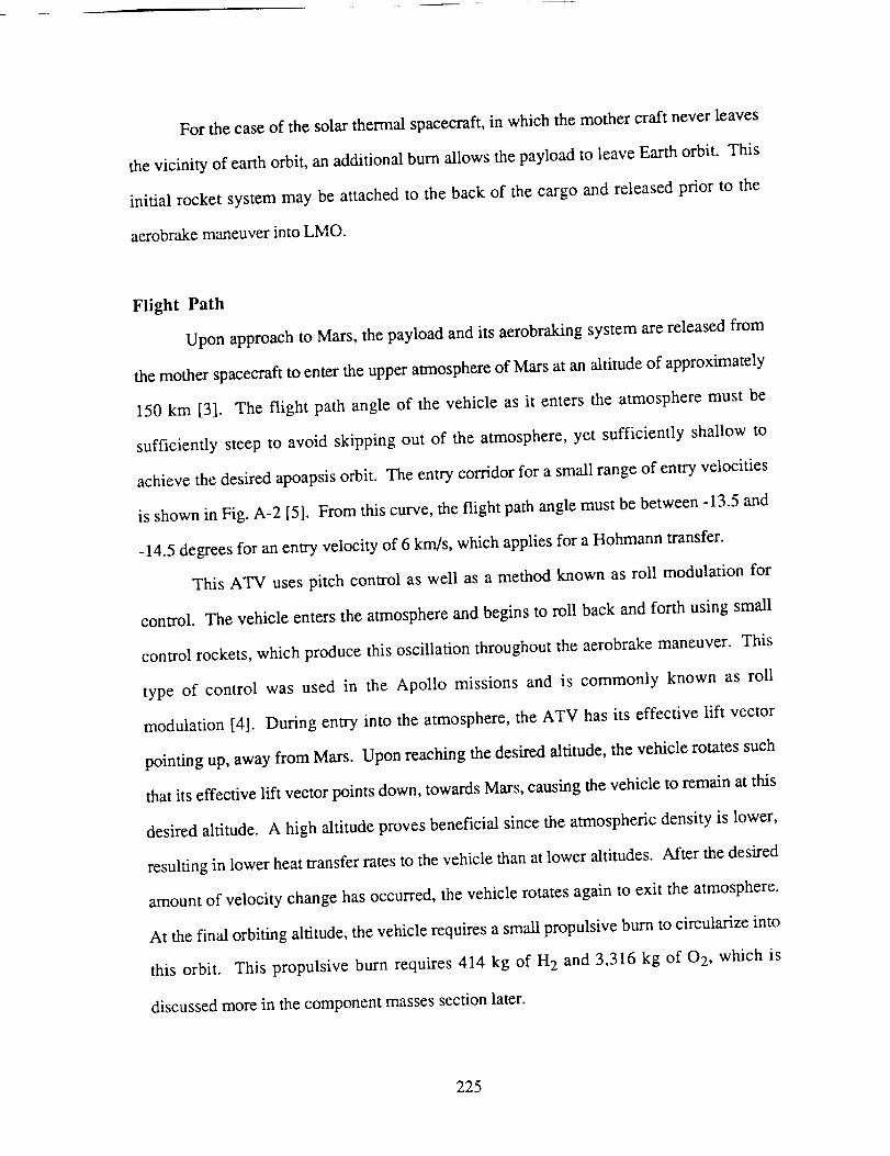
For thecaseof thesolarthermalspacecraft,in whichthemothercraft neverleaves
thevicinity of earthorbit, anadditionalburnallows thepayloadto leaveEarthorbit. This
initial rocket systemmay beattachedto the backof the cargoandreleasedprior to the
aerobrakemaneuverintoLMO.
Flight Path
Uponapproachto Mars,thepayloadandits aerobrakingsystemarereleasedfrom
themotherspacecraftto entertheupperatmosphereof Marsat analtitudeof approximately
150 km [3]. The flight path angleof the vehicle as it enters the atmospheremust be
sufficiently steepto avoid skipping out of the atmosphere,yet sufficiently shallow to
achievethedesiredapoapsisorbit. Theentrycorridor for asmallrangeof entryvelocities
is showninFig. A-2 [5]. Fromthiscurve,theflight pathanglemustbebetween-13.5and
-14.5degreesfor anentryvelocityof 6 km/s,whichappliesfor aHohmanntransfer.
This ATV usespitch control aswell as a methodknown asroll modulationfor
control. Thevehicleentersthe atmosphereandbeginsto roll backandforth usingsmall
control rockets,which producethisoscillationthroughouttheaerobrakemaneuver.This
type of control was used in the Apollo missions and is commonly known as roll
modulation[4]. During entry into the atmosphere,the ATV has its effective lift vector
pointing up,awayfrom Mars. Uponreachingthedesiredaltitude,thevehiclerotatessuch
thatits effectivelift vectorpointsdown,towardsMars,causing the vehicle to remain at this
desired altitude. A high altitude proves beneficial since the atmospheric density is lower,
resulting in lower heat transfer rates to the vehicle than at lower altitudes. After the desired
amount of velocity change has occurred, the vehicle rotates again to exit the atmosphere.
At the final orbiting altitude, the vehicle requires a small propulsive burn to circularize into
this orbit. This propulsive burn requires 414 kg of H 2 and 3,316 kg of 0 2, which is
discussed more in the component masses section later.
225
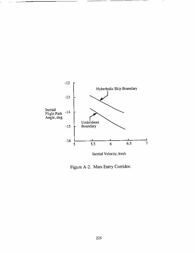
InertialFlightPathAngle, deg.
-12
-13
-14
-15
-16
HyberbolicSkipBoundary
I I I I
5 5.5 6 6.5 7
Inertial Velocity, km/s
Figure A-2. Mars Entry Corridor.
226
For anATV vehiclevaryinglift with roll modulation,thelift to dragratio (L/D) of
thevehiclemustbetwice thatof its flight averageL/D to accountfor unpredictabledensity
variations in the Martian atmosphere[1]. Figure A-3 showsthe L/D requirementfor
different entry velocitiesand a desiredapoapsisof 15,000km, accountingfor a safety
factor for density variations[5]. For themissionspresentedin this report, the desired
apoapsisis 300 km. For a desiredapoapsislower than15,000km, the dragof theATV
must be larger, and therefore,the L/D requirementwill be lower. Therefore,the L/D
requirementof 0.55 for anapoapsisof 15,000km is sufficient for thedesiredapoapsisof
300km for our mission. Theproposedraked-off sphereconehasaL/D of 0.6,makingit
anacceptableconfiguration[1].
Stability and Control
The stability of the vehicle is an important factor in the vehicle design. For the
raked-off sphere cone, force lines originating from the center of pressure may be drawn
rearward at each angle of attack (See Fig. A-4). These lines of force converge at a single
point called the metacenter. The location of this point is about 60% of the diameter of the
vehicle aft of the forward stagnation point [1,3]. The center of gravity, cg, of the ATV
must be forward of the metacenter to provide stability. The design for this mission has a 25
m frustum diameter so the metacenter is 15 m aft of the forward stagnation point as shown
in Fig. A-4. This is well aft of the cg location, thus the vehicle is quite stable. Referring
again to Fig. A-2, the desired flight angle of attack, called the trim angle, is achieved by
locating the cg of the ATV on one of the force lines drawn to the metacenter. The cg of the
ATV for this mission will be positioned to give a trim angle of -5.0 degrees so the L/D is
-0.55 without roll modulation [1].
Control is also required in addition to stability for the effectiveness of the vehicle.
Control of the vehicle involves an efficient system that requires no surface deflection. Two
methods to control lift are integrated to achieve satisfactory control in the unpredictable
227
.75
.70
.65
.60
I./D .55
.50
.45
.40
.35 5 5.5 6 6.5 7
Inertial velocity, km/s
Figure A-3. Mars aerocapture L/D requirement.
228
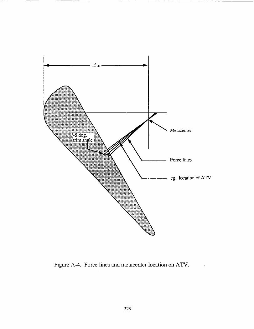
15m v
5 deg.an
Metacenter
Force lines
cg. location of ATV
Figure A-4. Force lines and metacenter location on ATV.
229
Martian atmosphere. Thesemethodsinclude roll modulation, which was discussed
previously,andpitchcontroltokeeptheangleof attackconstant,aswill bedescribedlater.
With roll modulation,thecalculationsfor theheatloading,drag,andlift of thevehicleare
dependentonly onheightandvelocity becauseof thefixed angleof attack.Therefore,the
overalltrajectorycalculationswill bemuchsimplerthanthecalculationsfor avehiclewith
variabletrim angleof attack.Furthermore,roll modulationprovidesa safetymarginin lift
whichallowsfor modificationsshouldadensityvariationoccurin theatmosphere.
In real gasflow, however,theangleof attackdeviatesfrom the desiredangleof
attackdueto thechangesin theflow temperatureandthedensitycausedbythedissociation
of thegas. This effectwasobservedin theSpaceShuttleandApollo missionswherethe
trim angledeviatedup to 40 from the expectedtrim angle,which decreasedthe lift by
10%[3]. Someof thiserrormaybeaccountedfor with the locationof thecg. However,
it cannotbecompletelyaccountedfor sincethereal gasvariationof trim angleof attack
varieswith the specificheatratio in non-equilibriumflow, which varieswith the density
andthevelocity.
Ratherthanallow realgaseffectsto changetheangleof attackandtheaerodynamic
characteristicsaswell, thepitchof theATV is controlledsuchthattheoriginal -5° angleof
attackis achievedandheldconstant.To accomplishaconstantangleof attack, thecg of
thevehicleis changedby shiftingfuel betweenthetanks(SeeFig. A-l). This methodof
control is known aspitch controlwheretheoxygencanbe shiftedbetweentanksduring
flight sotheconstantangleof attackis achievedwith realgaseffects.This is thereasonfor
thepropellanttankconfigurationshownin Fig. A-1. By separatingthepropellant tanks,
propellantmaybetransferredtochangethevehiclecenterof gravityto thedesiredlocation.
The reasonpitch control is not used alone is due to the complications in the
trajectorycalculations,asmentionedearlier. This typeof controlchangestheaerodynamic
characteristicswith angleof attack. If the angleis increasedmorenegatively,the lift will
increaseandthedrag will decrease.Thus,to havetheneededcontrol andto drastically
230
reducethecomplexityof thecontrolcalculations,bothroll modulationandpitchcontrolare
needed.
Flow Impingement
SincetheATV flies in hypersonicflow, theflow actuallyturnsasit flowsover the
edgeof the aeroshell.For zerolift, this baseturning angleis about15°, andasangleof
attackis increasedmorenegatively,thelift increasesandthebaseturninganglecanbecome
asmuchas35° [3]. It is thereforenecessaryfor thecargoon thebacksideof theATV to
haveclearancesuchthat theflow doesnot impingeon anyafter-bodysurface. The two
reasonsfor thisarethermalprotectionandsteadyflow requirements.If theflow impinged
on a surface such as the cargo cannisters, the heat transfer rates on that surface would
increase greatly, and additional thermal protection would be required to cover the surface.
Furthermore, the location of the flow impingement would not be steady. Therefore,
variable moments on the vehicle would result, causing the vehicle to shake violently. To
avoid this, the cargo cannisters are positioned lying down with the forward portion deeper
in the aeroshell as shown in Fig. A-1. This positioning eliminates the flow impingement
problem and provides a very stable ATV, as described earlier.
Heat Transfer
There are three types of heat transfer that affect the design of the thermal protection
system (TPS) of the ATV. The convective heat transfer to the ATV is dependent on the
nose radius, r n, the velocity, v, the density of the atmosphere, p, and the ratio of the wall
enthalpy of the ATV to the total enthalpy, gw. The convective heat transfer rate, qc,
(W/cm 2) is given as [6,7]:
qc = 1.35x10- V3.04{1 - gw)(A-l)
231
This equation assumesa fully catalytic wall. The density at a given altitude, y, is
determined by [4]
p = pie-_Y (A-2)
where, for altitudes above 36 km in the Martian atmosphere, the atmospheric density, Pi, is
0.03933 kg/m 3 and the scaling constant, 13i, is 1.181x10 -4 m -1 [4,10].
For velocities in the Martian atmosphere above 8 km/s, there will be radiative
heating of the aeroshell [6]. For velocities below this value, such as in the present mission,
there will be radiation of heat away from the aeroshell. Not accounting for the dissociation
of the atmospheric gas, the radiative heat transfer rate from the aeroshell, qr, is
determined by
qr = _{T4w - T_o) (A-3)
where c_ is the Stefan-Boltzmann constant (a = 5.67x10 "8 W/m 2 K4), E is the emissivity of
the aeroshell material, T w is the wall temperature, and T O is the free stream temperature.
The temperature variation in the Martian atmosphere is found from experimental data [8].
Assuming one-dimensional heat transfer, the conductive heat transfer rate qd,
through the aeroshell material is given as
qd = h_Tw - Tb) (A-4)
where k is the thermal conductivity of the aeroshell
temperature, and h is the thickness of the aeroshell material.
The integrated heat load is determined from [9]
-2_ ChSQ -- m(V_- Vo2c_
material, T b is the backface
(A-5)
232
wherem is themassof theATV, veis theentryvelocity, vo is theexit velocity outof the
atmosphere(whichwasassumedto be3 krrdsfor themissionsin this report),Chis a non-
dimensionalheattransfercoefficient(theStantonnumber),CDis thedragcoefficient,S is
the surfaceareaof theATV, andA is thecrosssectionalareaof theATV. Before the
integratedheatloadcanbecalculated,Chmustbefoundfrom theheattransferrateto the
aeroshell,_t,by usingtheequation[9]
dl = ChpW3S (A-6)
where q was determined using the previous equations.
Because the aeroshell material has a finite temperature range, the maximum wall
temperature is determined for the worst possible flight condition for the ATV. For this
extreme case, the ATV is assumed to be traveling with a velocity of 6 km/s at an altitude of
50 km. Assuming emissivity e = 0.8, the maximum T w is 1,470 K for the extreme case,
assuming a fully catalytic wall. Because this temperature is too low to cause a significant
amount of dissociation, this approximation is reasonably accurate to within 10%
error [6,7].
Shielding Materials
The aeroshell material is optimized according to several parameters. To minimize
the ATV mass, a low density material is desired. The thickness of the material will be
minimized for low thermal conductivities, high emissivities, and low catalycities of the
material. The material must be able to support light structural loads and possess a low
coefficient of thermal expansion to provide dimensional stability and rigidity. It is also
desired that the aeroshell material be chemically inert with respect to the Martian and Earth
233
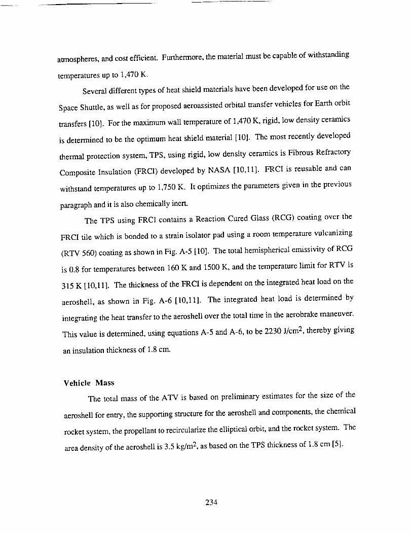
atmospheres,andcostefficient. Furthermore,thematerialmustbecapableof withstanding
temperaturesupto 1,470K.
Severaldifferenttypesof heatshieldmaterialshavebeendevelopedfor useon the
SpaceShuttle,aswell asfor proposedaeroassistedorbital transfervehiclesfor Earthorbit
transfers[10]. For themaximumwall temperatureof 1,470K, rigid, low densityceramics
is determinedto be theoptimumheatshieldmaterial [10]. Themostrecentlydeveloped
thermalprotectionsystem,TPS,usingrigid, low densityceramicsis FibrousRefractory
CompositeInsulation (FRCI) developedby NASA [10,11]. FRCI is reusableandcan
withstandtemperaturesup to 1,750K. It optimizestheparametersgiven in theprevious
paragraphandit isalsochemicallyinert.
The TPS usingFRCI containsa ReactionCuredGlass(RCG) coatingover the
FRCI tile which is bondedto a strainisolatorpadusingaroom temperaturevulcanizing
(RTV 560)coatingasshownin Fig. A-5 [10]. Thetotal hemisphericalemissivityof RCG
is 0.8 for temperaturesbetween160K and 1500K, andthetemperaturelimit for RTV is
315K [10,11]. The thickness of the FRCI is dependent on the integrated heat load on the
aeroshell, as shown in Fig. A-6 [10,11]. The integrated heat load is determined by
integrating the heat transfer to the aeroshell over the total time in the aerobrake maneuver.
This value is determined, using equations A-5 and A-6, to be 2230 J/cm 2, thereby giving
an insulation thickness of 1.8 cm.
Vehicle Mass
The total mass of the ATV is based on preliminary estimates for the size of the
aeroshell for entry, the supporting structure for the aeroshell and components, the chemical
rocket system, the propellant to recircularize the elliptical orbit, and the rocket system. The
area density of the aeroshell is 3.5 kg/m 2, as based on the TPS thickness of 1.8 cm [5].
234
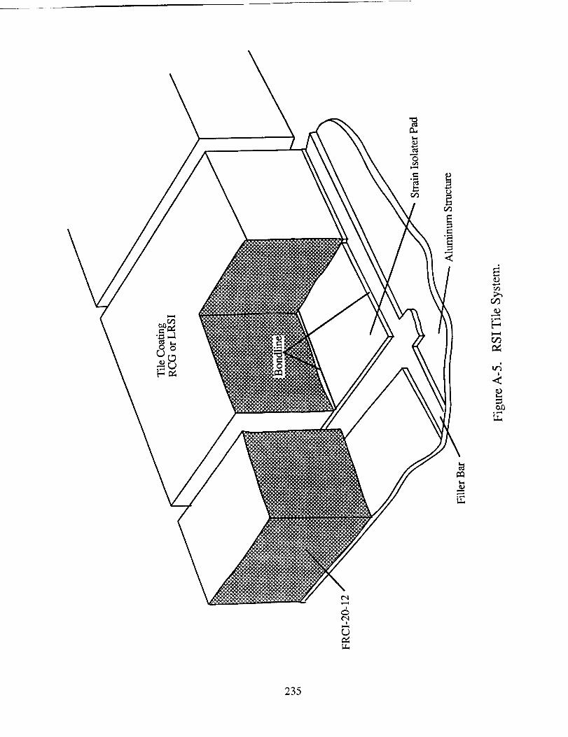
O
<
b-,
IA
¢-q
,5¢',1
235
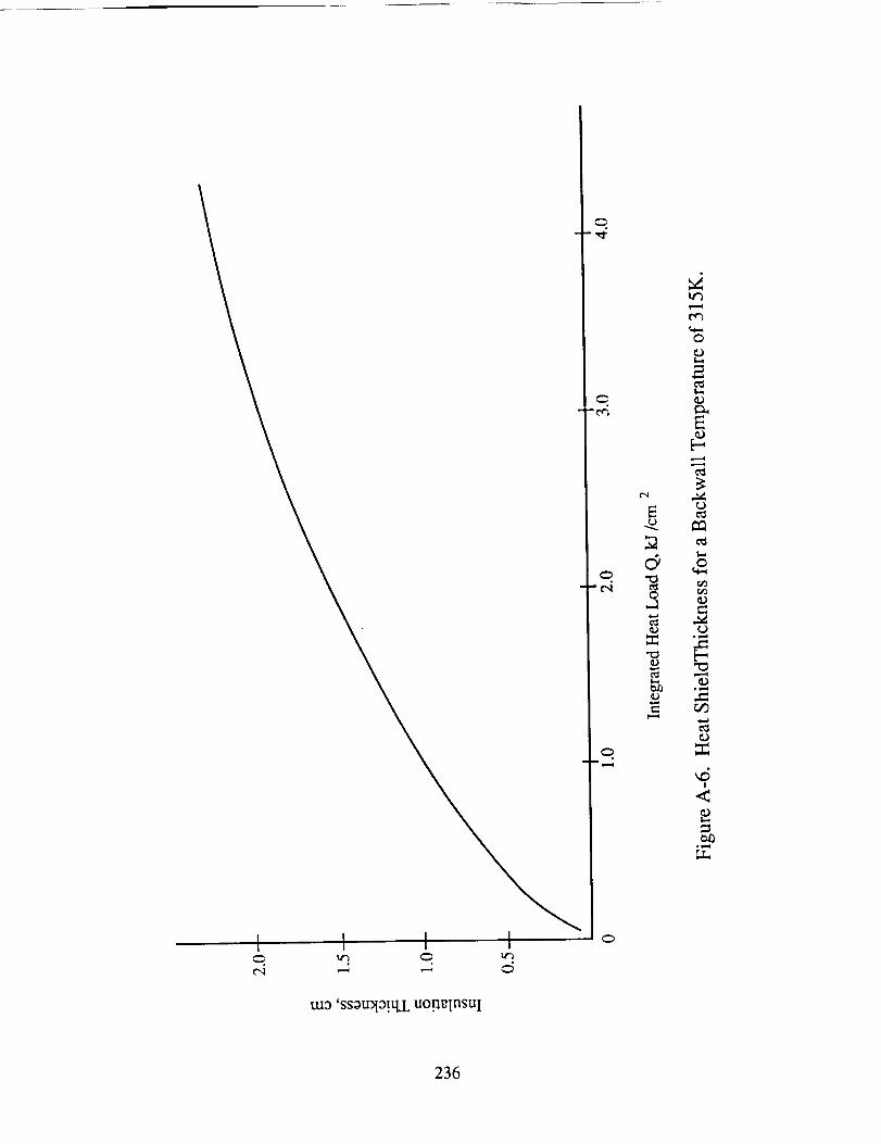
I I I Ie,i ,---, ,--, c5
-e,i
¢,q
c_
t,.¢3
0
e.-,
2
,,6!
<
_0
;.r..,
tuo 'ssotrdo!qz uogrlnsuI
236
Thetotal surfaceareaof theaeroshellis approximatedbythatof acircle havingthemajor
axisfrustumdiameter,d. Themassof theaeroshell,mA,maybedeterminedfrom:
mA= 3.5_d2 (A-7)
Basedon preliminary approximationsfor aerobrakecomponentmasses[12], the
loadbearingsupportstructuremass,ms, is givenby:
ms= 8.75(rnc)°'65 (A-8)
wherethecomponentmass.rnc,is theATV mass,mT, lessthepayloadmass.Themassof
thesecondarystructure,mss,usedto connectcomponentsto eachotheris givenby:
mss= 0.2mds (A-9)
wherethedry stagemass,mds,is theATV massminusthepayloadandfuel masses.The
massof thepropulsionsystem,naps,includingpropellantfeedpipes,is givenby:
mps= 0.0042mT (A- 10)
Thepropellantrequiredto recircularizethe orbit cannotbeaccuratelyestimated,
since for control and navigationreasons,the best trajectory, which will modulate its
effective lift somewhatduring flight, has not beenspecified for this vehicle design.
However, Tauberestimatesthe velocity increment for recircularizing the orbit to be
approximately200-300m/secfrom aHohmanntransfertoanapogeeheightof 300km and
anL/D of -0.2 [13]. Therefore,a velocity incrementof 300 rrgs wasassumedfor the
preliminary analysis. An integration of the equations of motion of the ATV, with a
constant L/D of -0.2, a ballistic coefficient of 75 kg/m 2, and a C D of 1.4 (the design of the
ATV in this report [ 1,4]), indicates a velocity increment of 60 m/s was required at apogee
237
to recircularizetheorbit. Sincetheactualtrajectorywill vary from this approximation,
somepre-aerobrakingattitudeandtrajectoryadjustmentswill beneededbeforeentry,and
in theeventof anunforeseenemergencyabortmissionon thefirst try, additional propellant
must be carried. Thus, the conservative estimate of the 300 m/s velocity increment is
considered for the propellant requirement calculations.
The propellant mass is determined from the mass fraction:
- e (A-11)
where mf is the final mass, m i is the initial mass, Av is the velocity increment, and u e is the
exhaust velocity. The exhaust velocity assumed for the hydrogen oxygen propellant rocket
system is 4,760 m/sec.
The total propellant mass required to circularize the orbit consists of 414 kg of
hydrogen and 3,316 kg of oxygen. In a liquid state, the cryogenic densities at 100 kPa and
The radius of the77.4 K are 1070 kg/m 3 for oxygen and 70.8 kg/m 3 for hydrogen.
storage tanks may be determined from:
v _p (A-12)
where m and p refer to the mass and density of either hydrogen or oxygen. In this
calculation, the mass of each tank is one half of the total value since there are two hydrogen
tanks and two oxygen tanks for the vehicle. The mass of the propellant tanks, rapt, may
then be scaled from a 100 kg tank with a radius of 2.2 m which can withstand g loadings
greater than our 1.5 g requirement [14]:
mpt = 10(_2.-_f (A-13)
238
The multi-layer insulation is composedof both dacronandmylar, andhasadensityof
60kg/m3. Themassof therequiredinsulation,mins,is determinedfrom:
mins= 80p(r3o- _) (A-14)
wherethesubscriptson theradii refer to the innerandexterior radii of the insulation. A
vapor shield venting systemkeepsthe tanks at the cryogenic temperature. A 1 cm
thickness is assumed to account for the tank thickness and the venting shield thickness.
Also, this vapor shield accrues a small loss of hydrogen propellant during the mission.
This loss is proportional to surface area and inversely proportional to insulation thickness.
The mass loss rate, mloss, in kg/hr, is scaled from the mass loss rate of a given
tank [14,15]:
mloss = 0.0012667 r2t (A-15)
where r is the tank radius, and t is the insulation thickness. An insulation thickness of
15 cm was chosen for the tanks by minimizing the total mass accounting for the hydrogen
propellant lost during the transfer time to Mars and the mass of the insulation. This
resulted in 130 kg total vented hydrogen during the trip to Mars. The oxygen mass loss
was assumed to be negligible with this insulation thickness.
The above analysis indicates that the total mass of the ATV is 62,660 kg including
the 50,000 kg payload yielding an aerobrake mass penalty of 20%. Table A- 1 summarizes
the component masses of the ATV.
239
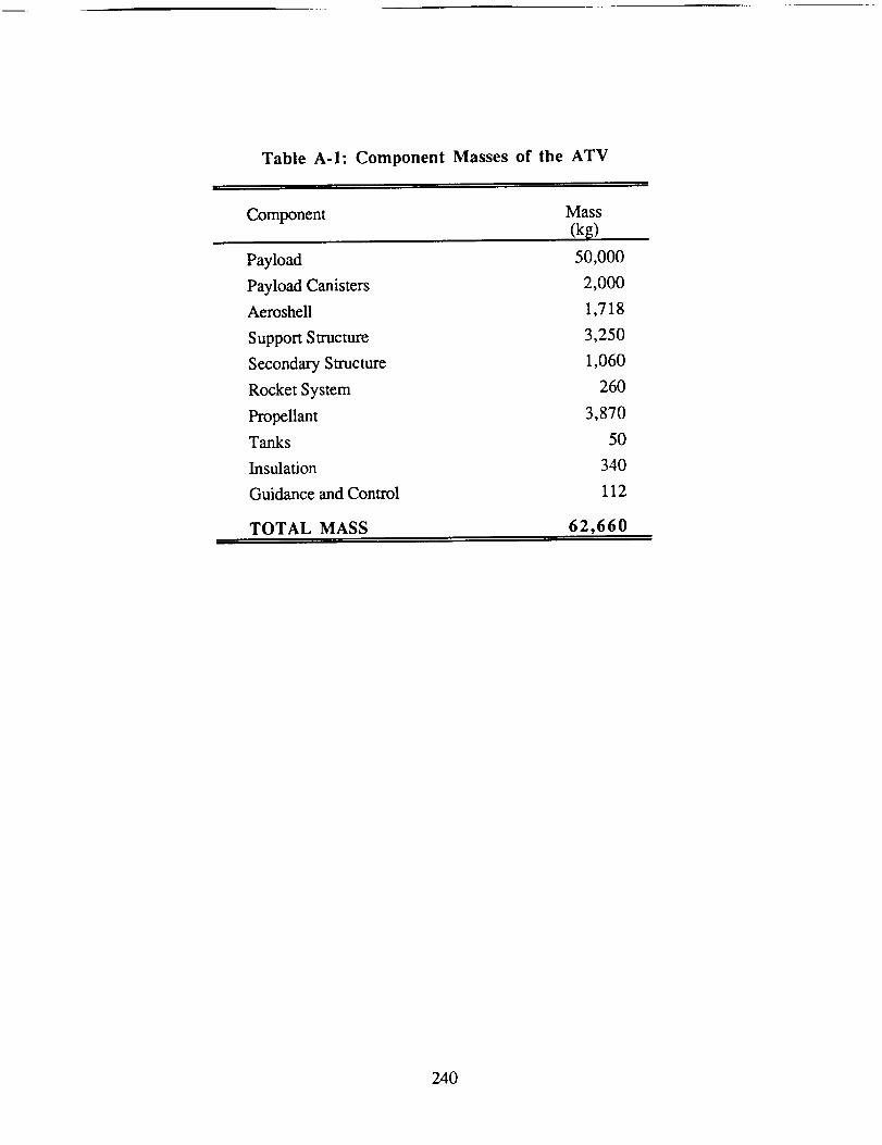
Table A-I: Component Masses of the ATV
Component Mass
(k_)
Payload 50,000
Payload Canisters 2,000
Aeroshell 1,718
Support Structure 3,250
Secondary Structure 1,060
Rocket System 260
Propellant 3,870
Tanks 50
Insulation 340
Guidance and Control 112
TOTAL MASS 62,660
240
NOMENCLATURE
A
ATV
cg
CD
Ch
d
FRCI
gw
h
Isp
1
LID
m
q
Q
r
ri
ro
RCG
RTV
S
t
T
To
TPS
cross-sectional area of aeroshell
Aeroassisted transfer vehicle
center of gravity
drag coefficient
heat transfer coefficient
freestream diameter (major axis)
Fibrous Refractory Composite Insulation
wall to total enthalpy ratio
aeroshell thickness
specific impulse
thermal conductivity
lift-to-drag ratio
mass of ATV
heat transfer rate
integrated heat load
radius
inside radius of insulation
outside radius of insulation
reaction cured glass
room temperature vulcanizing
surface area of aeroshell
insulator thickness
temperature
freestream temperature
thermal protection system
241
Ue
v
Y
exhaust velocity
vehicle velocity
altitude
mv
g
P
(Y
velocity increment
emissivity
density of atmosphere
Stefan-Boltzman constant (5.67 x 10⁻⁸ W/m2 oK4)
242

Subscripts
a
b
C
d
ds
e
f
i
n
o
ps
pt
r
s
ss
t
T
w
aeroshell
backface
convective
conductive
dry stage
entry
fmal
initial
nose
exit
propulsion system
propellant tank
radiative
support structure
secondary structure
tank
total
wall
243
REFERENCES
. Park, C. and Davies, C. B., "Aerothermodynamics of Manned Mars Mission",
AIAA Paper No. 89-0313, 1989.
, Walberg, G. D., "A Survey of Aeroassisted Orbit Transfer", Journal of Spacecraft
and Rockets. Vol. 22, pp. 3-18, Jan.-Feb. 1985.
, Park, C., "A Survey of Aerobraking Orbital Transfer Vehicle Design Concepts",
AIAA Paper No. 87-0514, 1987.
, Davies, C. B. and Park, C., "Aerodynamics and Thermal Characteristics of
Modified Raked-Off Blunted Cone", AIAA Paper 86-1309, June, 1986.
5, Hill, O. and Wallace, R. O., "Manned Mars Mission Vehicle Design Requirements
for Aerocapture", NASA TM-89320, 89321, June, 1985.
, Tauber, M. E. and Bowles, J. V., "Atmospheric Maneuvering During Martian
Entry", AIAA Paper No. 88-4345, 1988.
, Tauber, M. E., Menees, G., and Adelman, H., "Aerothermodynamics of
Transatmospheric Vehicles", AIAA Paper No. 86-1257, 1986; also Journal of
Aircroft, Vol. 24, pp. 594-602, March, 1987.
8. Kaplan, D, "Environment of Mars, 1988", NASA TM-100470, 1988.
244
o Allen, H. J. and Eggers, A. J. Jr., "A Study of the Motion and Aerodynamic
Heating of Missiles Entering the Earth's Atmosphere at High Supersonic Speeds",
NACA Technical Note 4047, 1957.
10. Goldstein, H., "Development of Ceramic Thermal Protection Materials for
Aerobraking Orbital Transfer Vehicles", 37 th Pacific Coast Regional Meeting of the
American Ceramic Society, Oct. 28-31, 1984.
11. Pitts, W. C. and Murbach, M. S., "Heatshield Design for Transatmospheric
Vehicles", AIAA Paper No. 86-I258, 1986.
12. Kroll, K., NASA Johnson Space Center, Private Communication, Feb., 1989.
13. Tauber, M., NASA Ames Research Center, Moffett Field, CA, Private
Communication, Feb., 1989.
14. Terre, C. N., "Low Pressure Light-Weight Cryogenic Propellant Tank Design for
the Space-Based Orbital Transfer Vehicle", AIAA Paper No. 86-6916, 1986.
15. Eberhardt, R. N. and Fester, D. A., "Shuttle Compartment Cryogenic Liquid
Storage and Supply Systems", AIAA Paper No. 89-1509, 1981.
245
APPENDIX B
Mathematical Model of Thermal Characteristicsin Thruster Chamber
Melanie Miller
A computer code was generated in order to determine the shape and heat transfer
characteristics of the plasma inside the laser thruster chamber. The mathematical model
was developed by Keefer et al [1] and is a 2-D, steady state representation of a laser
supported plasma in a circular cross-section channel. Two independent equations are used
to describe the thermal flux upstream and downstream of the plasma center. The thermal
flux, 01, upstream of the plasma is given by:
01 = 8KvSo(RL]Rc)ZAnJo(xo_)_ 0.5a(1 + x'-)x (B-l)
where r is the distance from the center of the cylinder and x is the distance upstream from
the plasma center. SO is the intensity of the incident laser radiation into the working fluid,
Jo is a Bessel function of the first kind, and Xon is the n th zero of Jo. Kv is the absorption
coefficient of hydrogen, which is 2.0398 x 10 -2 cm -I. This value was found from
Fig. B-l, which is the absorption at a pressure of 10 atm. R L is the radius of the laser
beam in the fluid, and R C is the radius of the chamber. The radius of the chamber is 13
cm. and ot denotes the upstream conditions of the fluid:
C uot = 90 p_. (B-2)
In Eq. B-2, Po is the upstream density of the fluid, taken to be 8.24 x 10 -4 g/cm 3 for 10
atm, and u is the upstream velocity, determined to be 0.133 crn/s for our mass flow rate.
246
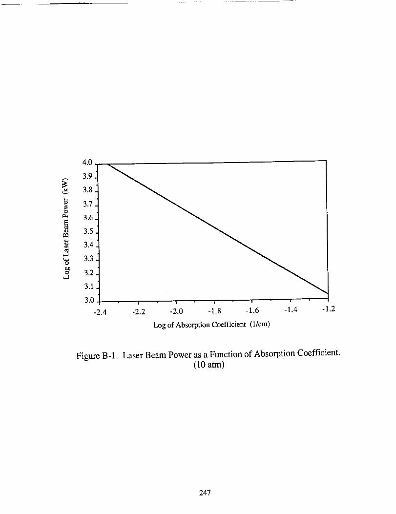
0
Q
-2.0 -1.8 -1.6
Log of Absorption Coefficient (1/cm)
Figure B-1. Laser Beam Power as a Function of Absorption Coefficient.(10 atm)
247
_.is the thermalconductivity, which is 0.0057J/(cm K s) for hydrogenat 10atm [1].
Anis acoefficientdeterminedfrom
(Xon(RLaC))An = Jl((2_,_onj2(Xon)!_(x.n, 1)+ 2Kv]) (B-3)
where J1 is a Bessel function of the first kind. x n' is determined from
4X'n=71 + {_-_)[(Xon/Rc_ +m] (B-4)
where m is the radiation loss coefficient, which is 875 cm -2 at 10 atm [1]. The thermal flux
downstream of the plasma center is given by:
02 8KvSo(RL/Rc_e-K'ZBnJdxon/_r--i-It _"_.CnJ Xo r
B n and Cn are coefficients determined from
-[ _-_ 2Kv)tA°Bn- L(,+'.- 1)-
[(0_(X'n + 1)).+_ 2KvlAnCn =L (_X'n-- 1)- 2Kv) f"
(B-6)
(B-7)
The mathematical model above only calculates thermal flux values, 0, which need
to be converted into temperatures. Keefer et al. [1] assumed that the thermal conductivity
of the hydrogen was constant over the temperature gradients. A better approximation was
determined using a linear approximation derived from thermal conductivity tables [2]. The
increase in thermal conductivity as a function of temperature was approximated to be linear
248
for temperaturevalues between5,000 and 18,000K. This assumption yields the
following:
T- 1233.5+ 1.062x10⁶[1.7161x10"6- 2.124x10"6V0.393- 0] 03-8)
where T is the temperature of the hydrogen gas in the absorption chamber. Temperatures
evaluated using this program will tend to diverge from actual temperature values when the
calculated temperature approaches 17,000 K. This is due to the linear assumption made
about the thermal conductivity.
The functions Jo and J1 and the associated zeros used in equations B-I and B-5
were attained from O'Neil [3].
249

NOMENCLATURE
A n
Bn
Cn
Jo
J1
Kv
r
R
RE
So
T
U
Xon
constant coefficient
constant coefficient
constant coefficient
Bessel function of the zeroth order
Bessel function of the first order
absorption coefficient
radius
radius of absorption chamber
radius of laser beam
radiation intensity
temperature
upstream velocity
n th zero of Jo
Po
t
%n
coefficient of upstream conditions
absorption coefficient
upstream density
constant coefficient
250
REFERENCES
, Keefer, D.R. and Crowder, H., "A Two-Dimensional Model of the Hydrogen
Plasma for Laser Powered Rocket", AIAA Paper No. 82-0404, Jan., 1982.
. Grier, N. T., "Calculation of the Transport Phenomena of Ionizing Atomic
Hydrogen", NASA TN D-3186, April, 1966.
, O'Neil, P. V., Advanced Engineering Mathematics, Wadsworth Publishing
Company, Belmont, CA, pp. 302-305, 1987.
251
APPENDIX C
Analytical Methods Used in the Design of theMPD Propelled Spacecraft Structure
Tad A. Unger
Beam theory is a quick and easy way to analyze the truss beams that make up the
array platform, and the payload and main body structure. Using this for a cantilever beam,
the moment applied at the root of the truss is
M = p°L22 (C-1)
where Po is the distributed load per length, and L is the length.
Reaction stresses in the elements provide the resistance to the applied moment. For
the box beam the element stresses are found from statics to be
M
o = (wAtube) (C-2)
where M is the moment from Eq. C-l, w is the distance between the top and bottom
elements of the mast, and Atube is the cross sectional area of the tube element.
The critical buckling stress for a pinned element is found from Euler's equation
(7t2EItube /
(C-3)
where C is 1 for the pinned boundary conditions, E is the modulus of elasticity, Itube is the
area moment of inertia of the tube element, and 1 is the length of the element.
252
To estimatethe natural frequency,Rayleigh'smethodwasused. The assumed
modeshapewasthatfor adistributedloadon acantileverbeam.Thisgivesanexpression
for thelowestfrequency:
EItruss
o_ = 12.46 t/)tmL3_- (C-4)
where Itrus s is the area moment of inertia of the truss beam about its neutral axis and m is
the mass distributed along the length.
To calculate the mass of the array structure the total length of the elements must be
calculated.
From Fig. C-1, the following relations are apparent:
L= A. (L_f-fl2Aw)
Lw-
C2
where A is the total array area, among the two platforms, 1 is the horizontal length of a C1
cell, and C2 is the number of cells in the vertical direction.
The final equations are written in terms of L, C1, and C2, the input variables.
Length calculation of one side of the platform:
]2 length of longitudinals:
/ c2
253
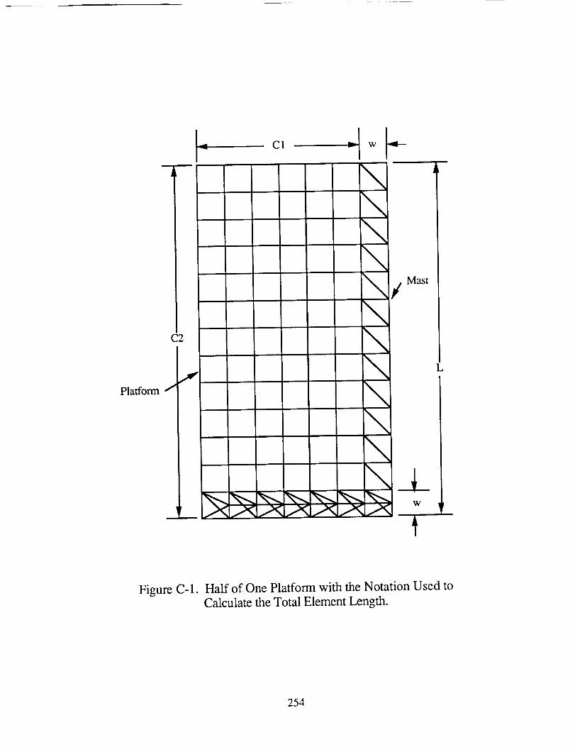
Platform
C2
L c, J LI_ -I w
\
\\\/\\\\\\
Mast
L
\A_
Figure C-1. Half of One Platform with the Notation Used to
Calculate the Total Element Length.
254
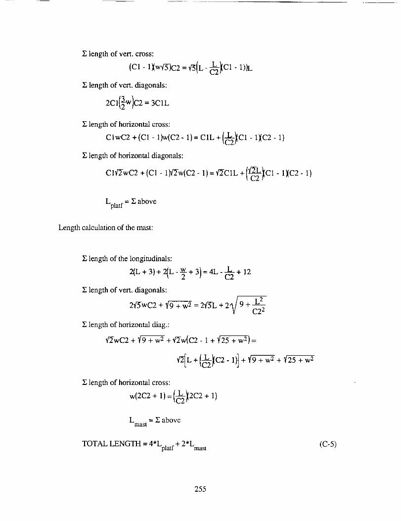
Z lengthof vert. cross:
{C1-1){wq-5-)C2 = qS{L-_22_Cl- 1))L
Z length of vert. diagonals:
2C1(}w)C2 = 3elL
Z length of horizontal cross:
ClwC2 +(C1-1)w(C2-1)=C1L+(_22_Cl-1}(C2-1)
Z length of horizontal diagonals:
C1!/'_7wC2 +(C1-1_2-w(C2- 1)=',r2C1L + 1¢-'2-L_(c1 - 1}(C2-1)_C2/'
Lplat f = Y_above
Length calculation of the mast:
Z length of the longitudinals:
2(L+ 3)+ 2(L-_+ 3}=4L-c--_2 + 12
Z length of vert. diagonals:
2"_-wC2 + _ + w 2 = 2_5-L + 2 9 -_ C2 2
Z length of horizontal diag.:
q-2-wC2 + _ + w 2 + q-2-w(C2 - 1 + t/25 + w 2 } =
g length of horizontal cross:
wl=+ +1/L = Z above
mast
TOTAL LENGTH = 4*Lplat f + 2*Lmast (c-5)
255
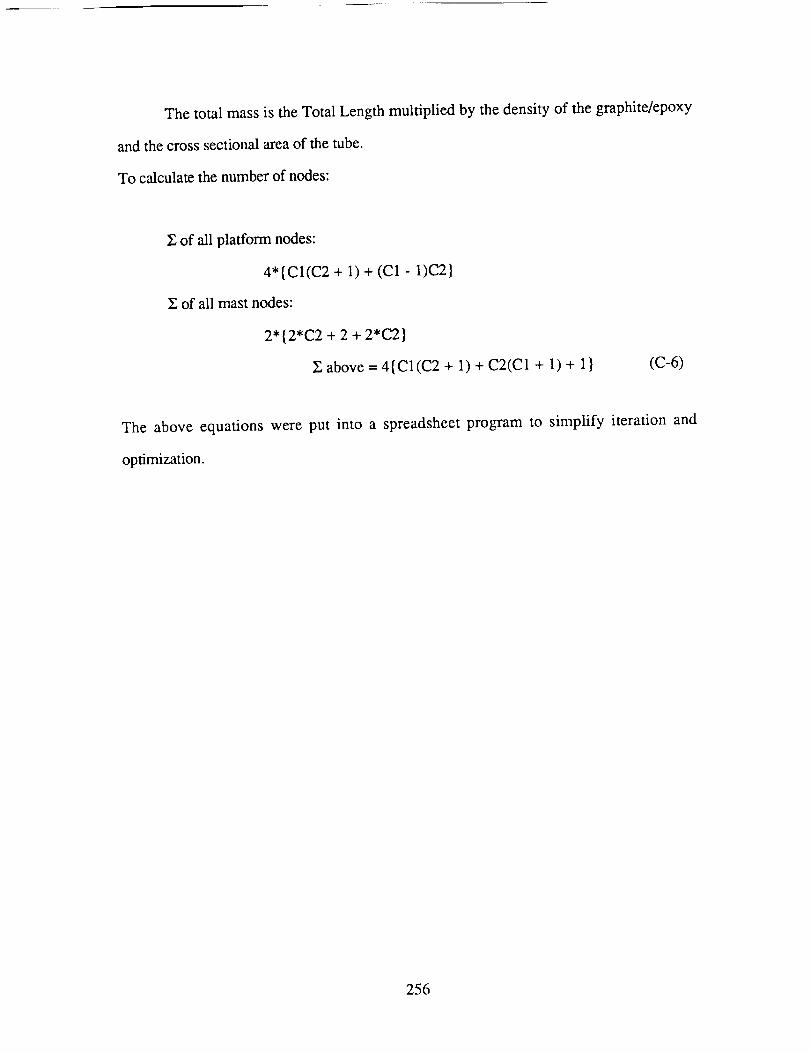
Thetotal massis theTotalLengthmultiplied by thedensityof thegraphite/epoxy
andthecrosssectionalareaof thetube.
To calculatethenumberof nodes:
Z of all platformnodes:
4"{C1(C2 + 1)+ (C1 - 1)C2}
Z of all mastnodes:
2"{2"C2 + 2 + 2"C2}
Zabove = 4{C1(C2+ 1)+ C2(C1+ 1)+ 1} (C-6)
The above equationswere put into a spreadsheetprogram to simplify iteration and
optimization.
256

NOMENCLATURE
A
Atube
C1
C2
E
Itruss
Itube
1
L
m
M
Po
W
Area of the solar array
Cross sectional area of the tube elements
Number of cells from the mast to the edge of the platform in the
horizontal direction
Number of cells in the vertical direction
Young's Modulus in the longitudinal direction
The area moment of inertia of the mass beam
The area moment of inertia of the tube elements
The length of a C1 cell in the horizontal direction
The overall length of one array platform
Mass distributed along the mass beam
Applied moment
Distributed load
Length of cells in the vertical direction
f-0 n Natural frequency
257
APPENDIX D
Numerical Trajectory Calculation Programs
Barbrina Dunmire
Jacqueline Auzias de TurenneNeil Phelps
The following programs are those used to determine the orbital trajectories of the
three solar-powered spacecraft. The computational technique used takes the equations of
motion of the spacecraft and expresses them as first order differential equations using state
variables. These differential equations are integrated using a standard fourth order Runge-
Kutta numerical integration technique. The initial conditions, celestial body constants, and
thrust program can be altered so that trajectories may be computed for a variety of primary
bodies, starting orbits, and spacecraft configurations. Lift and drag terms may also be
included in the governing equations of motion, making it possible to calculate the trajectory
of the aerobraking payload system.
The programs also include an iterative method for determining the minimum amount
of propellant necessary for the mission by calculating the amount of propellant required for
an estimated initial spacecraft mass. If the final mass is less than the dry mass of the
spacecraft, then the initial mass is increased. If the final mass is more than the dry mass of
the spacecraft, then the initial mass is decreased. The final mass of the spacecraft is then
recomputed, and the process is repeated until the final mass is nearly equal to the dry mass
of the spacecraft. The propellant mass is then the initial mass minus the dry mass of the
spacecraft.
The programs used in the analysis of the three solar-powered spacecraft are listed
below and appear on the following pages.
258
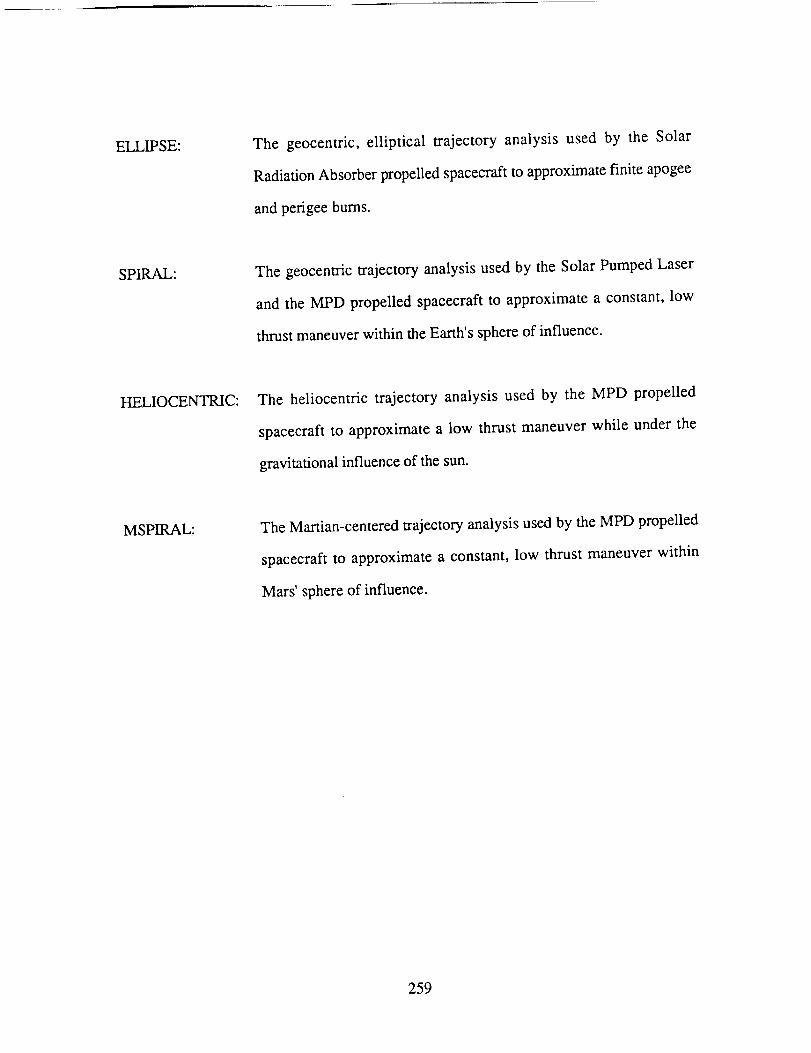
ELLIPSE: The geocentric, elliptical trajectory analysis used by the Solar
RadiationAbsorberpropelledspacecraftto approximatefinite apogee
andperigeebums.
SPIRAL: The geocentrictrajectoryanalysisusedby the SolarPumpedLaser
andthe MPD propelledspacecraftto approximatea constant,low
thrustmaneuverwithin theEarth'ssphereof influence.
HELIOCENTRIC: The heliocentric trajectory analysisused by the MPD propelled
spacecraftto approximatea low thrust maneuverwhile under the
gravitationalinfluenceof thesun.
MSPIRAL: TheMartian-centeredtrajectoryanalysisusedby theMPD propelled
spacecraftto approximatea constant,low thrust maneuverwithin
Mars' sphereof influence.
259

PROGRAM ELLIPSE
program ellipse
C
* _%4:* * 7':* * * 9= * * * * * * _ * * * * _=* 7%* I%7'=* 9¢* * * * * 7%* * _ * * * * _'c_ _':_=* * * * * * * * * * * * 7'=7% * _ * *C
c 7'= Ellipse is the main calling program for the integration of *
c * the equations of motion of the spacecraft while under the *
c * gravitational influence of the Earth. *7%* * * 7%* * * * * * * 9C* * 7'=* _'=* * * 4=* * * * * * * _'__'=9= * * * 7'_* _ * * _ * _'=* * * 9=* _ * 9¢ 9:* * * * _ 9=* * * 7%* *
C
C
implicit double precision(a-h,o-z)
dimension xo(20),xx(20)
C
c * 'md' is the dry mass of the ship which includes everything 7'=
c * except the propellant mass required for an individual *
c _ manuever. *
c * 'mp' is the estimated propellant mass required for a given *
c * manuever.
c * 'amln'
c * 'amax'
c * 'theta'_':_'=* * * _'=_c* 7'=* 9=* * * * * 9= * * _'=* 4=* * * * 9__'=* * * * * 7'=* _'=* * _'=7'=_'=7%* * _'_* * 7'¢7'=* * 9:* _'=* * _'=7'¢_'=* * 7'¢* *
C
C
md=43814
mp=24000
amin=.6
amax=l.2
theta=5/180*3.14159
open (file = 'escape', status = 'new', unit = 7)
write (7,*) 'orbital trajectory data'
write (7,*) 'data is in the following order'
c write (7,*) 'time rdot r phidot phi velocity'
C
9=* * * * _':* 7%* * * * 9= * _'__'=7'=7'=9= * * 9¢ _%9=* 9=* * 9¢* 9=* 9=7% * 7'=* 7'¢* * * 9= _'=7%* 4= * 7%* * * * _'_* * * * 7%* 9_ _'=* * * * * * * 9_* 9=C
c _': 'xo' is the array of the initial conditions where: x_(1) = rdot, 7'=
c * x (2) = r, x (3) = phidot, x (4) = phi, and x (5) = mass. *
C _':* 7'_* _'-_"9=7%* * 9¢ * * 9¢9:* ",_-_"* 7'=7%7?* * * 7%_'=9¢* _'=9: 9=_'=_'-7_ * * 9=9,"* 9:7'=* * 9= _'=* * 7% * * 7'-_"* * _'_* _'=* * * * * * _'_9=_'=* * * * _'=9=* _'=
C
50 xo (1) =0
xo (2) =6878145
xo (3) =0. 00110678256
xo(4)=O
xo (5) =rod+rap
C
='=* 4= ='=* 7'=7% * ='=7'¢=':* _ 7'=7'¢* * ='=7':_ * 7':7'=7%* 9¢_'=* 9=4=* * 7'=4:* * * 4=* _ 9:* ='=* * 4¢* 7':_ * 4=7'¢* * * 4=* _'=_'=I%* 7'¢7'=* * * 7'=_'=W =':C
c * The following are variables passed through to the integration ==
c * subroutine. 'in' is a flag, 'nv' is the number of variables in *
c * the equations of motion, 'to' is the initial time, 'tp' is the *
c * final time (stopping the loop), and 'dtint' is the interval that _'_
c _'= the integration routine breaks each time loop down. *
C
c * 've' is the escape velocity ot a given radius _
c _'= 'vv' is the instantaneous ship velocity _':
c * 'vo' is the velocity required to undertake a hohmann transfer to _:
C _'= mars f:
C
in=O
nv=5
to=O
tp=43200000
dtint=63
do 200 t=5640,tp,lO0
call ellrk4(to,t,dtint,xo,xx,nv,in)
vv= (xx (i)*'2+ (xx (2)*xx (3))*'2)**0.5/1000
vo = (2.94**2+ (2*3. 986* I0"'5/xx (2) * 1000) )**. 5
c write (7,100) t,xx(1),xx(2),xx(3),xx(4),vv
c 100 format (ell.5,1x,dll.5,1x,dll.5,1x,dll.5,1x,dll.5,1x,dll.5)
150 ve = (2000*3.986012eOS/xx (2))**0.5
if (vv.gt.(vo-.75)) go to 250
200 continue
c ***************************************************************
c * This next scheme is a method to check that the final *
c * propellant consumption, as determined from the burn time, *
c * is euqal to the initial estimate. If not, the *
c * process is repeated with a new estimate. *C ****************************************************************************
C
250 mpr=xo (5)-xx (5)
if (abs(mpr-mp).it.lO0) go to 350
if (mpr.gt.mp) go to 300
if (mpr.lt.mp) go to 325
300 mp=mp+(mpr-mp)
go to 50
325 rap=rap- (mp-mpr)
go to 50
350 write (7,*) 'congratulations you have escaped earth orbit'
write (7 *) 'vest, v, and vo',ve,vv,vo
write (7
write (7
write (7
write (7
write (7
write (7
*) 'total time of spiral (days)',t/3600/24
*) 'mass of propellant consumed',xo(5)-xx(5)
*) 'total number of revolutions',xx(4)/2/3.14159
*) 'orbital radius at escape (km)',xx(2)/lO00
*) 'mp',mp
*) 'VO',VO
end

subroutine ellrk4(to, tp, dtint,xo,xx,nv,_n)
c
* This is a fourth order runge-kutta numerical integration *
subroutine courtesy of Stephen Paris, flight mechanics *
specialist, Boeing Aerospace Division of the Boeing Company.
c
C
c
c
c
c
c
C *
Ellrk4 integrates a set of 'nv' Ist order ordinary differential *
equations from xo(to) to xo(tp) with step size 'dtint' The *
differential equations are contained in subroutine fcn, and *
the values computed are returned to ellipse. *
C *******_***************_***********_****_**_*_****_**_*********_**_
implicit double precision(a-h,o-z)
c ommon/nwvc i/ time, xv (I 00) ,d (i 00)
common/rkblck/vs (20) ,ds (20) ,xs (20)
dimension xo (20) ,xx (20)
external ellfcn
if (in.eq.o) time=to
900 continue
h=tp-time
if (abs(h).gt.dtint)h=sign(l.0d0,h)*dtint
h2=h/2
hd=h/6
* This routine initializes the variables. If the variables *
* have already been initialized, this routine is overlooked. ** * * * * _'¢* * * * * * * * _'¢* * * * * * * * * * * _'__'¢* * * * _ * * * * * * * * * * * * _ * * _':* * * * * * _'_* * * * * * * *
if (in.eq.l) go to 1300
in=l
do ii00 i=l,nv
xv(i)=xo (1)ii00 continue
tn=to
c
do 1200 i=l,nv
ds (i)=d(i)
xs (i) =xv(i)
1200 continue
c
1300 continue
,..,., 4'._._ , 4,., ., _*..,°.,.,.4,_,o.,.,.4,._,..,.,. , 4, , .,..u4, _,.4,..,._ .,. ,°4,..,._. _..4,. ,
* Make first estimate of canter state. *
do 1400 i=l,nv
xv(i)=xs(i)+h2*ds(i)
1400 continue
time=tn+h2
call ellfcn
c
c * Revise estimate with derivative at center. *
C
do 1600 i=l,nv
vs (i)=ds (i)+2. O0*d (1)
xv (i) =xs (1) +h2*d (i)
1600 continue
call ellfcn
C
c * Make first estimeate of state at end of step.
C
do 1800 i=l,nv
vs (i) =vs (i) +2.00*d(1)
xv (i) =xs (i) +h*d (1)
1800 continue
tlme=tn+h
call ellfcn
do 1810 i=l,nv
vss=h6 * (vs (i) +d(i))
xs (i) =xs (i)+vss
xv(i) =xs (i)
1810 continue
C
C
do 1820 i=l,nv
ds (i)=d(1)
1820 continue
C
C
C
C
C
c * Final estimate based on derivative at center and both ends, *
c * with double weight on the center estimates. *
C
C
call ellfcn
* Update the time for the next step. _':
tn=time
C
C
c * End: copy state ot 'xx' *
if(time.ne.tp) go to 900
do 2000 i=l,nv
xx (i) =xv (i)
2000 continue
C
return
end
C

subroutine ellfcn
c
c * Ellfcn is the derivative evaluation routine for runge-kutta *
c * numerical integration routine. The values of t,x,and d _'=
c * are passed thru the common block. *
c * The differential equations are of the following form: *
c * d(n) = dx(n)/dt = f(x(1), x(2) .... x(nv) ). *
c
implicit double precision (a-h,o-z)
common/nwvcl/t, x (100) ,d (I00)
c
C
c * The constatns defined below are as follows: *
c * g = acceleration due to gravity at the planet's surface *
c * ro = radius of the Earth *
c * f = thrust of the spacecraft *
c * pmdot = propellant mass flow rate *
c
g=9.80665
ro=6378145
c
c
c * The following determines the angular position of the *
c _': spacecraft between 0 and 360 degrees. *
C _'_""/_"";?";%"_': _;" _" ='[ ':';"";'__'; ';'__ ";'_'_'_'.;%_'¢ ';'c'_'_'";'_ ';'_"";'_"';\" _'¢ ";'_ "_, _"_" ';%"_'_'_'_''_'__'¢ '_'__'¢ '_'c'";': ;'¢"';'_ ";%"_ "_%"";'_"_'_";'c"_'c ";%";%"_'_ _'¢ ";'_";'_";%"";'c"_'¢ ";'_":_'¢"_'_"
c
s=x (4)
rev=O.O
if (s.lt.6.283) go to 200
rev=S/2/3. 14159
s=s-lnt (rev)*2*3. 14159
c
c * The following is a sequence of steps which determines the *
c _= firing angle about the perigee of the ellipse and checks *
c * to see if the spacecraft is within this range. *
C _':_'__':_'¢_'¢_'¢_'¢_':_'¢_'__'__'¢_':_'¢_':_'__'=_'¢_':_'¢=" _'¢_'¢_'__'¢_'__'=_'¢_'¢_'¢_':_'¢_'__'=_'¢_':_'__'__'__'__'__'¢_'__'¢_':_'r_ _'__':_'c_':_'__ _'__'__'¢_'¢_':_'¢_':_'¢_'c_'_
c
200 ang=amin+ (amax-amin)/60_':int (rev)
if (s.lt.(3.14159-.6458)) go to 300
if (s.gt.(3.14159+.6458)) go to 300
f=100
pmdot=-0. 004
go to 400
300 f=O.0
pmdot=0.0
C
c
c * State Dictionary: _
c _': r = radius of the spacecraft's orbit *
c _': phi = true anomaly measured from initiation of manuever *
c _': m = instintaneous mass of the spacecraft *
c =': x(1) = dr/dt ::
c * x(2) = dr :':
c _'_ x(3) = d(phi)/dt :_c * x(4) = phi _=
400 t emp--x (2) _'_× (3) *_'_2-g_':r o*'2/(x (2)) **2+f/x (5) *s in (theta)
d(1)=f_'_cos (theta)*x (1)/x (5) / (x (1)*'2+ (x (2)*x (3)) _'_*2)**0.5+temp
temp=2*x (1) *x (3)/x(2)
d (3) -- f_'_cos (theta)_'_x (3)/x (5) / (× (1) _'_'2+ (x (2) _'_x(3)) _'_'2) **0.5-t emp
d(4) =x (3)
C
d (5) =pmdo t
C
return
end

PROGRAM SPIRAL
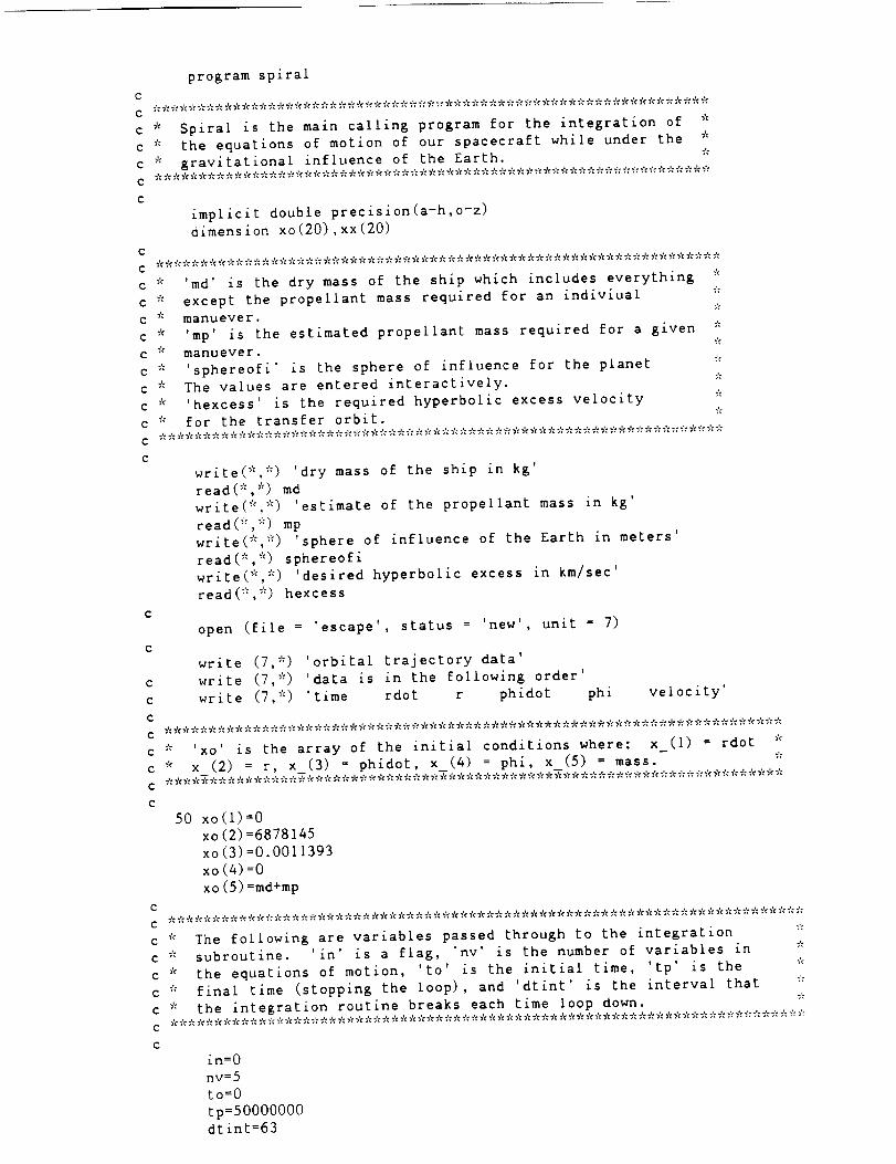
program spiral
C
C * * * * * * * * * * * * * * * * * * * * * * * * * * * * * * * * * * * * * * * * * * * * _ * * _ * * * * * * * * * * * * * * *
c * Spiral is the main calling program for the integration of *
c * the equations of motion of our spacecraft while under the *
• gravitational influence of the Earth. *• * * * * * * * * * * * * * * * * _': _: * * * * * * * * 7': * * * * * * * * * * * * * * * * _ * * _ * * * * * _? * * * * * * * * *
implicit double precision(a-h,o-z)
dimension xo(20),xx(20)
C
C * * * * * * * * * * * * * * * * * * * * * * * * * * * * * * * * * * * * * * * * * * _'¢* * * * * * * * * * * * * * * * * * * * *
c * 'md' is the dry mass of the ship which includes everything *
c * except the propellant mass required for an indiviual *
c * manuever. *
c * 'mp' is the estimated propellant mass required for a given *
c * manuever. *
c * 'sphereofi' is the sphere of influence for the planet *
c * The values are entered interactively. *
c * 'hexcess' is the required hyperbolic excess velocity *
c * for the transfer orbit. *
C
C
C
C
C
C
C
C
C
write(*,*) 'dry mass of the ship in kg'
read(*,*) md
write(*,*) 'estimate of the propellant mass in kg'
read(*,*) mp
write(*,*) 'sphere of influence of the Earth in meters'
read(*,*) sphereofi
write(*,*) 'desired hyperbolic excess in km/sec'
read(*,*) hexcess
open (file = 'escape', status = 'new', unit = 7)
write (7,*) 'orbital trajectory data'
write (7,*) 'data is in the following order'
write (7,*) 'time rdot r phidot phi velocity'
* 'xo' is the array of the initial conditions where: x (I) = rdot *
* x (2) = r, x (3) = phidot, x (4) = phi, x (5) = mass. ** * * * * * * * * * * * * * 7'=* * * * _'_* _'¢* * * * * * * 7'¢* * _'¢* * * * * * * * * * * * * * * * * * * * * * * * * * * * * * * * * * * * *
50 xo(1)=0
xo (2)=6878145xo (3)=0.0011393
xo (4)=0
xo (5)=md+mpC
C **********************************************************************************
c * The following are variables passed through to the integration *
c * subroutine. 'in' is a flag, 'nv' is the number of variables in *
c * the equations of motion, 'to' is the initial time, 'tp' is the *
c * final time (stopping the loop), and 'dtint' is the interval that *
c * the integration routine breaks each time loop down. *
C *********************************************************************************************
C
in=O
nv=5
to=O
tp=50000000
dtint=63
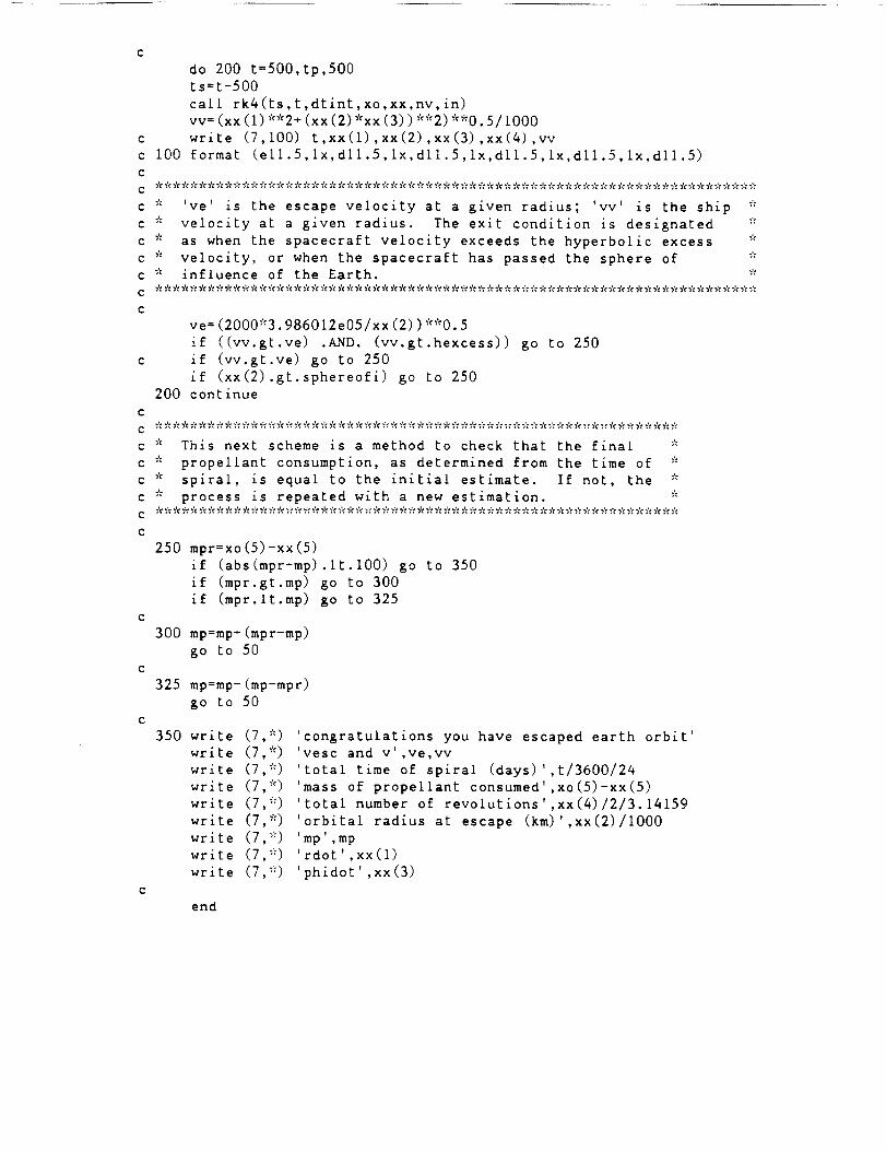
do 200 t=500,tp,500ts=t-500call rk4 (ts, t ,dt int, xo,xx,nv, in)vv: (xx (1) **2+ (xx (2) *xx (3)) **2) **0.5/1000
c write (7,100) t,xx(1),xx(2),xx(3),xx(4),vv
c I00 format (ell.5,1x,dll.5,1x,dll.5,1x,dll.5,1x,dll.5,1x,dll.5)
c
='¢ * ='_ _': * * * _'= * * * * * * ='= * * * * * * * * * * * * * * * * * * * * * * * * _'¢ * * * * ='t _'=* * * * * * _'_ * * * * ='c * * * _'¢ :'c * * * * * *
• 've is the escape velocity at a given radius; 'vv' is the ship *
• velocity at a given radius. The exit condition is designated *
• as when the spacecraft velocity exceeds the hyperbolic excess *
• velocity, or when the spacecraft has passed the sphere of *
• influence of the Earth. *
ve=(2000*3.986012e05/xx(2))**0.5
if ((vv.gt.ve) .AND. (vv.gt.hexcess)) go to 250
if (vv.gt.ve) go to 250
if (xx(2).gt.sphereofi) go to 250
200 continue
* This next scheme is a method to check that the final *
* propellant consumption, as determined from the time of *
* spiral, is equal to the initial estimate. If not, the *
* process is repeated with a new estimation. *
250 mpr=xo(5)-xx(5)
if (abs(mpr-mp).it.100) go to 350
if (mpr.gt.mp) go to 300
if (mpr.lt.mp) go to 325
300 mp=mp÷(mpr-mp)
go to 50
325 mp=mp-(mp-mpr)
go to 50
350 write (7,*) 'congratulations you have escaped earth orbit'
write (7,*)
wr_te (7,*)
wr_te (7, _)
write (7,*)
wrzte (7,*)
wrxte (7,*)
wr_te (7,*)
wr_te (7,*)
vesc and v',ve,vv
total time of spiral (days) ',t/3600/24
mass of propellant consumed',xo(5)-xx(5)
total number of revolutions',xx(4)/2/3.14159
orbital radius at escape (km)',xx(2)/lO00
mp',mp
rdot',xx(1)
phidot',xx(3)
end
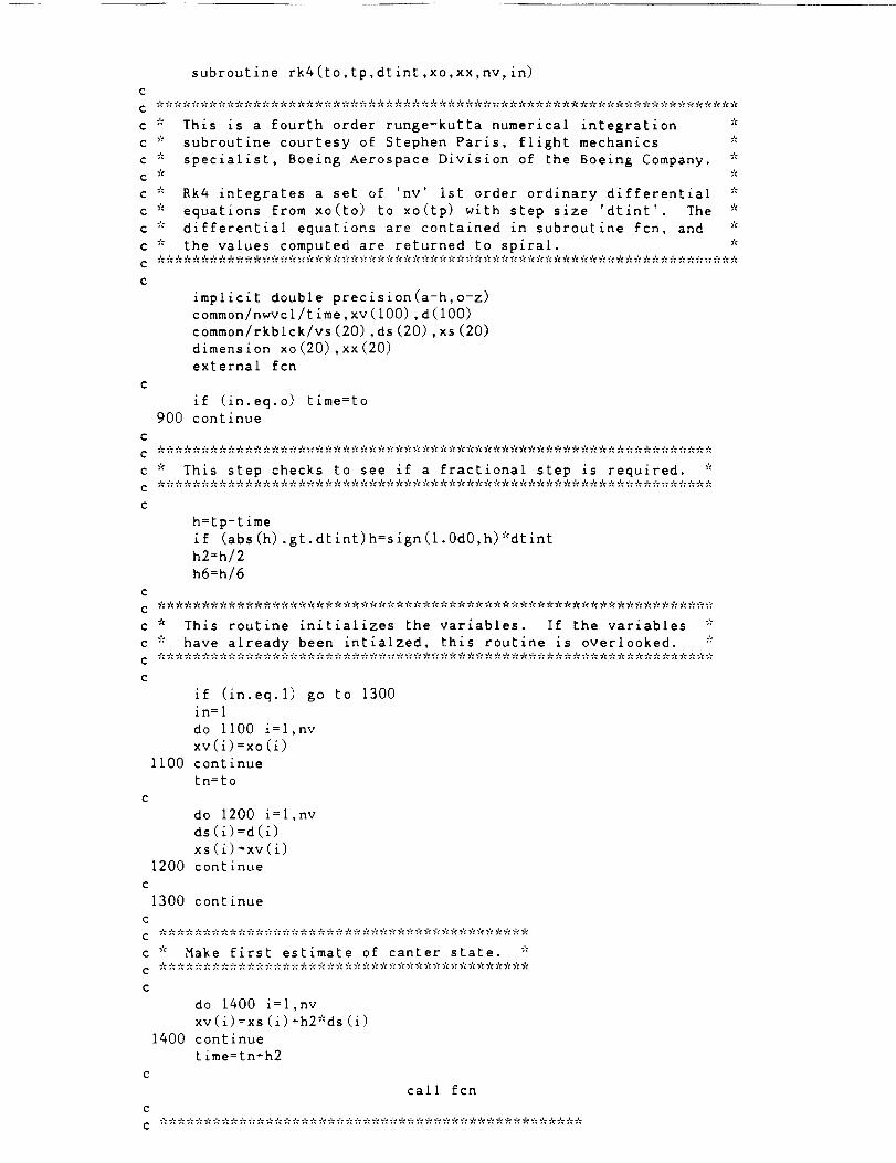
subroutine rk4(to,tp,dtint,xo,xx,nv,in)cc ********************************************************************
This is a fourth order runge-kutta numerical integration *subroutine courtesy of Stephen Paris, flight mechanicsspecialist, Boeing Aerospace Division of the Boeing Company.
C *
C
C
C *
C *
C *
c
C *
Rk4 integrates a set of 'nv' 1st order ordinary differential
equations from xo(to) to xo(tp) with step size 'dtint' The
differential equations are contained in subroutine fcn, and
the values computed are returned to spiral.
C **************************************************************************
c
implicit double precision(a-h,o-z)
common/nwvcl/time,xv(100),d(100)
common/rkblck/vs(20),ds(20),xs(20)
dimension xo(20),xx(20)
external fcn
if (in.eq.o) tlme=to
900 continue
c
c * This step checks to see if a fractional step is required. *
h=tp-time
if (abs(h).gt.dtint)h=sign(l.0d0,h)*dtint
h2=h/2
h6=h/6
* This routine initializes the variables. If the variables *
* have already been intialzed, this routine is overlooked. *
if (in.eq.l) go to 1300
in=l
do ii00 i=l,nv
xv(i)=xo(i)
Ii00 continue
in=to
do 1200 i=l,nv
ds (_):d(_)
xs (i)=xv(i)
1200 continue
do 1400 i:1,nv
xv(i)=xs(i)+h2*ds(i)
1400 continue
time=tn+h2
call fcn
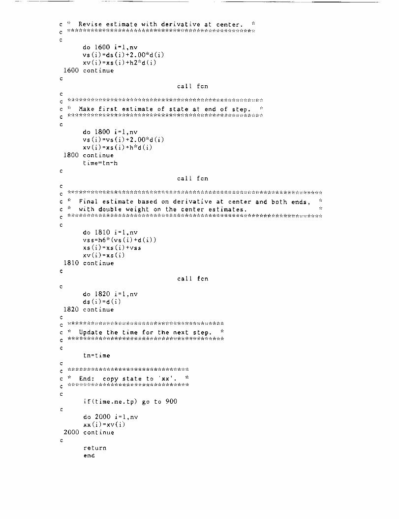
do 1600 {=l,nv
vs(i)=ds(i)+2.00*d(i)
xv(i)=xs(i)+h2*d(i)
1600 continue
call fcn
C
c * Make first estimate of state at end of step. *
do 1800 i=l,nv
vs(1)=vs(i)+2.00*d(i)
xv(i)=xs(i)+h*d(1)
1800 continue
time=tn+h
cal I fcn
C
c * Final estimate based on derivative at center and both ends, *
• with double weight on the center estimates. *
do 1810 i=l,nv
vs s=h6 * (vs (1) +d (i))
xs (i)=xs (i)+vssxv(i)=xs (i)
1810 continue
call fcn
do 1820 i=l,nv
ds (1)=d(1)
1820 continue
C
c * Update the time for the next step. *
¢ ****************************************
c
tn=time
C
C **************************************
c * End: copy state to 'xx'. *
C
if(time.ne.tp) go to 900
C
do 2000 i=l,nv
xx (1)=xv(i)
2000 continue
C
return
end
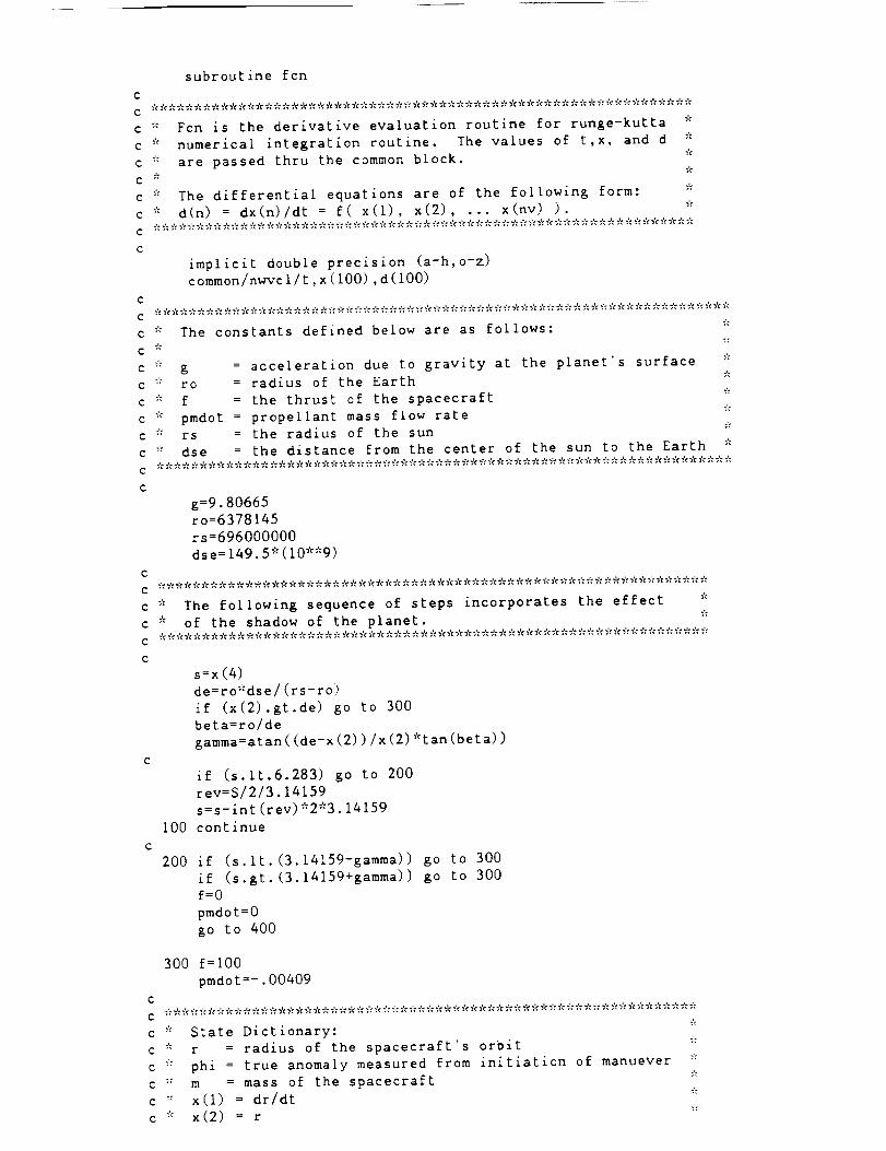
C
C
C Y¢
C _
C _'_
C *
C ¢_
C Y_
subroutine fcn
Fcn is the derivative evaluation routine for runge-kutta
numerical integration routine. The values of t,x, and d
are passed thru the common block.
The differential equations are of the following form:
d(n) = dx(n)/dt = f(x(1), x(2) .... ×(nv) ).
C
implicit double precision (a-h,o-z)
common/nwvcl/t, x (I00) ,d (100)
C
c * The constants defined below are as follows: *
C _'C ";'C
c * g = acceleration due to gravity at the planet's surface *
c _'_ ro = radius of the Earth *
c '_ f = the thrust of the spacecraft "_
c * pmdot = propellant mass flow rate "_
c '" rs = the radius of the sun _"
c `'_ dse = the distance from the center of the sun to the Earth *
C
g=9.80665
ro=6378145
rs=696000000
dse=149.5*(10**9)
* The following sequence of steps incorporates the effect *
* of the shadow of the planet. *
s=x(4)de=ro*dse/(rs-ro)
if (x(2).gt.de) go to 300
beta=ro/de
gamma=alan ((de-x (2))/x (2) *tan (beta))
if (s.lt.6.283) go to 200
rev=S/2/3.14159
s=s-int(rev)*2*3.14159
100 continue
200 if (s.lt.(3.14159-gamma)) go to 300
if (s.gt.(3.14159+gamma)) go to 300
f=0
pmdot=0
go to 400
300 f=lO0
pmdot=-.O0409
C
c ;'= State Dictionary: *
c * r = radius of the spacecraft's orbit _':
c _'= phi = true anomaly measured from initiation of manuever :_
c '_ m = mass of the spacecraft '_
c ": x(1) = dr/dr "_
c '_ x(2) = r "_

c * x(3) = d(phl)/dt *
c * x (4) = phi *
C * X (5) = m *
C
400 d (i) =f::x (i)/x (5) / (x (I)*'2+ (x (2) *x (3))*'2)*_'_0.5+x (2)*x (3) **2-
ig_':ro_:*2/x (2) _'_'2
C
d(2)=x(1)C
d (3) = f:':x(3)/x (5) / (x (I) :':'2+(x (2) *x (3)) *_':2)**0.5-2_':x (I) *x (3)/x (2)
C
d(4) =x (3)
C
d(5)=pmdot
C
return
end

PROGRAM HELIOCENTRIC
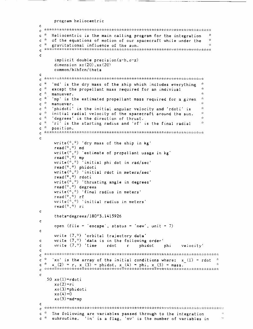
program heliocentric
C
c * Heliocentric is the main calling program for the integration *
c * of the equations of motion of our spacecraft while under the *
c * gravitational influence of the sun. *
C
implicit double precision(a-h,o-e)
dimension xo(20),xx(20)
common/blhfcn/theta
C
c * 'md' is the dry mass of the ship which includes everything *
c * except the propellant mass required for an indiviual *
c * manuever. *
c * 'mp is the estimated propellant mass required for a given *
c * manuever. *
c * 'phidoti' is the initial angular velocity and 'rdoti' is *
c * initial radial velocity of the spacecraft around the sun. *
c * 'degrees' is the direction of thrust. *
c _'_ 'ri' is the starting radius and 'rf' is the final radial *
c * position.
C
write(* *) dry mass of the ship in kg'
read(*,*) md
wr te(* *) estimate of propellant usage in kg'
read(*,*) mp
wr te(* *) initial phi dot in rad/sec'
read(*,*) phidoti
wr te(* *) initial rdot in meters/sec'
read(*,*) rdoti
wr te(* *) thrusting angle in degrees'
read(*,*) degrees
wr te(* *) final radius in meters'
read(*,*) rf
wr te(* *) initial radius in meters'
read(*,*) ri
theta=degrees/180*3.1415926
open (file = 'escape', status = 'new', unit = 7)
write (7,*) 'orbital trajectory data'
write (7,*) 'data is in the following order'
write (7,*) 'time rdot r phidot phi velocity'
* 'xo' is the array of the initial conditions where: x (i) = rdot *
c * x (2) = r, x (3) = phidot, x (4) = phi, x (5) = mass. _':
C
50 xo (1)=rdoti
xo (2)=ri
xo (3) =phidoti
xo(4)=0
xo (5) =rod+rap
C
c * The following are variables passed through to the integration _:
c * subroutine. 'in' is a flag, _nv' is the number of variables in :_
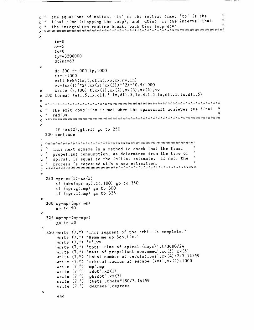
c * the equations of motion, 'to' is the initial time, 'tp' is the *c * final time (stopping the loop), and 'dtint' is the interval that *c * the integration routine breaks each time loop down. *C
C
in=O
nv=5
to=O
tp=43200000
dtint=63
do 200 t=lOOO,tp,lO00
ts=t-lO00
call hrk4 (ts, t,dtint, ×o, xx,nv, in)
vv = (xx (i)*'2+ (xx (2)*xx(3))*'2)**0.5/i000
c write (7,100) t,xx(1),xx(2),xx(3),xx(4),vv
c i00 format (ell.5,1x,dll.5,1x,dll.5,1x,dll.5,1x,dll.5,1x,dll.5)
C
c * The exit condition is met when the spacecraft achieves the final *
c * radius. *
if (xx(2).gt.rf) go to 250
200 continue
c * This next scheme is a method to check that the final *
c * propellant consumption, as determined from the time of *
c * spiral, is equal to the initial estimate. If not, the *
c * process is repeated with a new estimation. *_'¢* * * 5_ * * * _'¢* _ * * _'¢* _ * * _ * * * _ * _¢ 5¢ * _ * _'_* * 5¢ * _¢ * _% * * _'__ * * _'¢* * 5¢_'_* 5¢ 5_* * * 5_ _'¢5¢ * _'¢*
250 mpr=xo(5)-xx(5)
if (abs(mpr-mp).It.lO0) go to 350
if (mpr.gt.mp) go to 300
if (mpr.lt.mp) go to 325
300 mp=mp+(mpr-mp)
go to 50
325 mp=mp-(mp-mpr)
go to 50
350 write (7,*) 'This segment of the orbit is complete.'
write (7 *) 'Beam me up Scottie.'
write (7
write (7
write (7
wr_te (7
write (7
wr_te (7
wr_te (7
wr_te (7
wr
wr
*) 'V' ,VV
*) 'total time of spiral (days)',t/3600/24
*) 'mass of propellant consumed',xo(5)-xx(5)
*) 'total number of revolutions',xx(4)/2/3.14159
*) 'orbital radius at escape (km)',xx(2)/1000
*) 'rap' ,rap
*) 'rdot',xx(1)
*) 'phidot',xx(3)
_te (7,*) 'theta',theta*180/3.14159
te (7,*) 'degrees',degrees
end
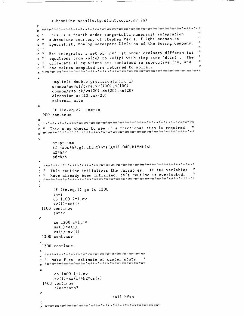
subrou£ine hrk4(to,tp,dtint,xo,xx,nv, in)
c
This is a fourth order runge-kutta numerical integration
subroutine courtesy of Stephen Paris, flight mechanics
specialist, Boeing Aerospace Division of the Boeing Company.
C _'_
c
c
c
c
c
c
c
c
c
* Rk4 integrates a set of 'nv' ist order ordinary differential
_: equations from xo(to) to xo(tp) with step size 'dtint' The
* differential equations are contained in subroutine fcn, and
* the values computed are returned to spiral.
implicit double precision(a-h,o-z)
common/nwvcl/time,xv(lOO),d(lO0)
common/rkblck/vs(20),ds(20),xs(20)
dimension xo(20),xx(20)
external hfcn
if (in.eq.o) time=to
900 continue
* This step checks to see if a fractional step is required. *
h=tp-time
if (abs(h).gt.dtint)h=sign(l.OdO,h)*dtint
h2=h/2
h6=h/6
c
c * This routine initializes the variables. If the variables *
c _': have already been intlalzed, this routine is overlooked. *
if (in.eq.l) go to 1300
in=l
do ii00 i=l,nv
xv(i)=xo(i)
II00 continue
in=to
c
do 1200 i=l,nv
ds (i) =d(i)
xs (i)=xv(i)
1200 continue
c
1300 continue
do 1400 i=l,nv
xv(i)=xs(i)+h2*ds(i)
1400 continue
time=tn+h2
call hfcn
, , , , ,., , , ,o .,..,..,..,..,° , , , ,o.,o , ,°.,o .,o .,o , .,o , .,.., ° .,° 4° .,. , .,o., .,o, ,° ,o .' .'o., .,° ,o _..,° .,.
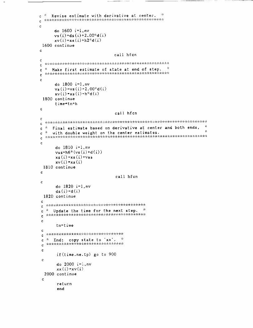
* Revise estimate with derivative at center. *
do 1600 i=l,nv
vs (i)=ds(i)+2.00*d(i)
xv (i) =xs (1) +h2*d(i)
1600 continue
C
call hfcn
do 1800 i=l,nv
vs(i)=vs(1)+2.00_d(i)
xv(1)=xs(i)+h*d(i)
1800 continue
time=tn+h
call hfcn
=: Final estimate based on derivative at center and both ends, *
• with double weight on the center estimates. *
do 1810 i=l,nv
vss=h6 * (vs (i) +d (i))
xs (i)=xs (i)+vssxv(i) =xs (i)
1810 continue
call hfcn
do 1820 i=l,nv
ds (i) =d(i)
1820 continue
=: Update the time for the next step. *
tn=time
C
C _ _ _¢ * _% _'__ 7'¢_ 7'__ _ _¢ 7'__ _ _ _ 7'¢_ _ _'__':_'__'__'¢_ _ _'¢_ 7'_
c 7'= End: copy state to 'xx'. *
if(time.ne.tp) go to 900
do 2000 i=l,nv
xx (i) =xv(1)
2000 continue
c
return
end
C
C
C
C
C
C
c
c * Make first estimate of state at end of step. ==

subroutine hfcnO
O
c * Fcn is the derivative evaluation routine for runge-kutta *
c * numerical integration routine. The values of t,x, and d *
c * are passed thru the common block. *
C
c * The differential equations are of the following form: *
c * d(n) = dx(n)/dt = f(x(1), x(2) .... x(nv) ). *
C
C
implicit double precision (a-h,o-z)
common/nwvcl/t,x(100),d(lO0)
common/blhfcn/theta
C *
C *
C *
C *
C
C
C
C
C
C
C
g = acceleration due to gravity at the planet's surface *
ro = radius of the planet *
f = the thrust of the spacecraft *
• pmdot = propellant mass flow rate *
g=274
rs=696000000
r = radius of the spacecraft's orbit *
phi = true anomaly measured from initiation of manuever *
m = mass of the spacecraft *
x(1) = dr/dt *
x(2) = r *
x(3) = d(phl)/dt *
x (4) = phi *
x(5) = m *
temp l=x (2) *x (3) **2-g_'=r s**2/(x (2)) **2+f/x (5) *s in (thet a)
d(1) =f'cos (theta)*x (i)/x (5) / (x (I) **2+ (x(2)*x (3) ) *'2) **0. 5
I +templ
d (i) =f*x (i)/x (5) / (x (i) **2+ (x (2) "=x(3)) **2) **0.5+x (2) *x (3) **2-
ig*r o**2/x (2) **2
d(2)=x(1)
temp2=2*x (1)*x (3)/x (2)
d (3) =f'cos (theta) *x (3)/x (5) / (x (I)*'2+ (x (2)*x (3) ) *'2) **0. 5
1 -temp2
d (3) = f"_x (3)/x (5) / (x (i) **2+ (x (2) *x (3)) **2) **0.5-2"x (i) "=x(3)/x (2)
d (4) =x (3)
d(5) =pmdot
return
end

PROGRAM MSPIRAL
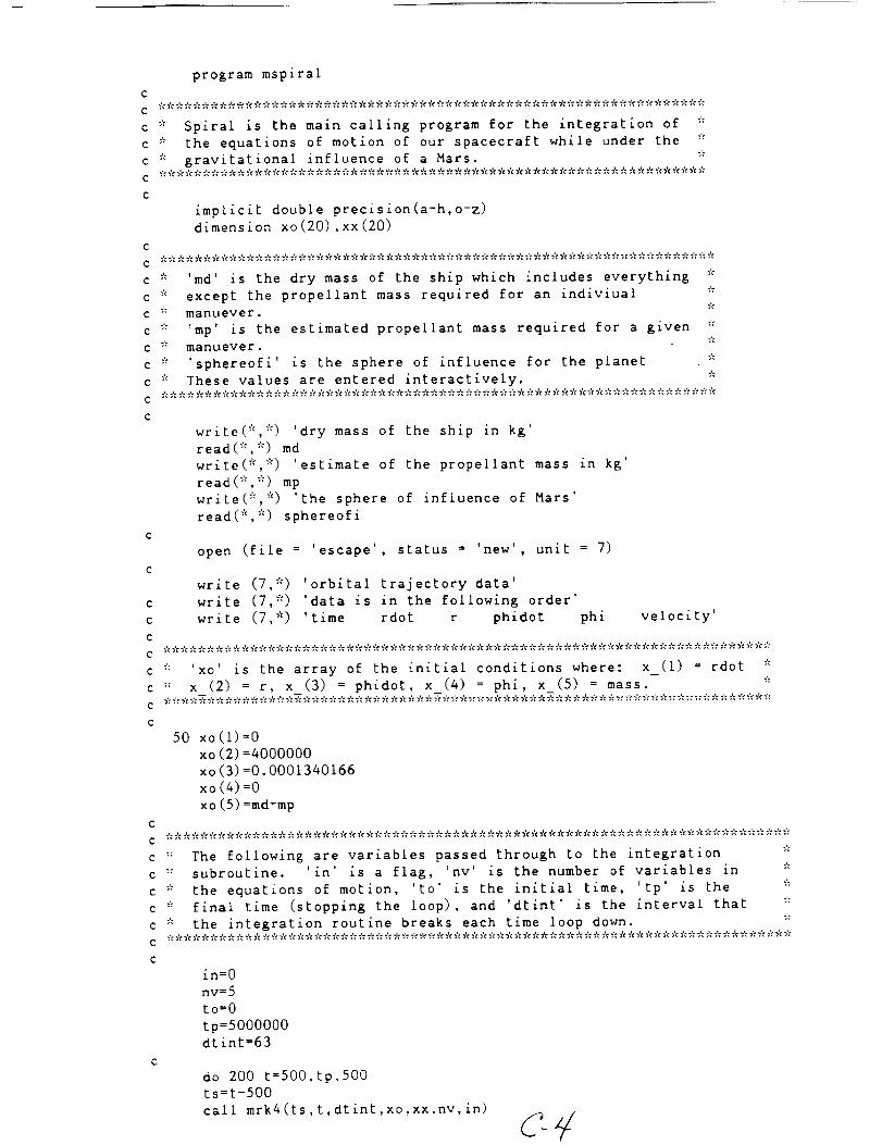
program mspiral
C
C
c * Spiral is the main calling program for the integration of *
c _= the equations of motion of our spacecraft while under the *
c * gravitational influence of a Mars. *
C
implicit double precision(a-h,o-z)
dimension xo(20),xx(20)
C
C
c * 'md' is the dry mass of the ship which includes everything *
c * except the propellant mass required for an indiviual *
c * manuever. *
c * 'mp' is the estimated propellant mass required for a given ::
c _'_ manuever. *
c * 'sphereofi' is the sphere of influence for the planet *
c * These values are entered interactively, e
C
C
write(_':, *) 'dry mass of the ship in kg'
read(*,*) md
write(*,*) 'estimate of the propellant mass in kg'
read(*,*) mp
write(e, * ) 'the sphere of influence of Mars'
read(*,*) sphereofi
open (file = 'escape', status = 'new', unit = 7)
write (7,*) 'orbital trajectory data'
write (7,*) 'data is in the followlng order'
write (7,*) 'time rdot r phidot phi velocity'
c * 'xo' is the array of the initial conditions where: x_(1) = rdot *
c * x (2) = r, x (3) = phidot, x (4) = phi, x (5) = mass. *
C
50 xo (i)=0
xo (2) =4000000
xo (3) =0.0001340166
xo(4)=O
xo (5) =rod+rap
C
C
c _'_ The following are variables passed through to the integration
c * subroutine. 'in' is a flag, 'nv' is the number of variables in *
¢ "_ the equations of motion, 'to' is the initial time, 'tp' is the "_"
c '_ final time (stopping the loop), and 'dtint' is the interval that *
c * the integration routine breaks each time loop down. ""
C
C
in=O
nv=5
to=O
tp=5000000
dtint=63
do 200 t=5OO,tp,500
ts=t-500
call mrk4(ts,t,dtint,xo,xx,nv,in)
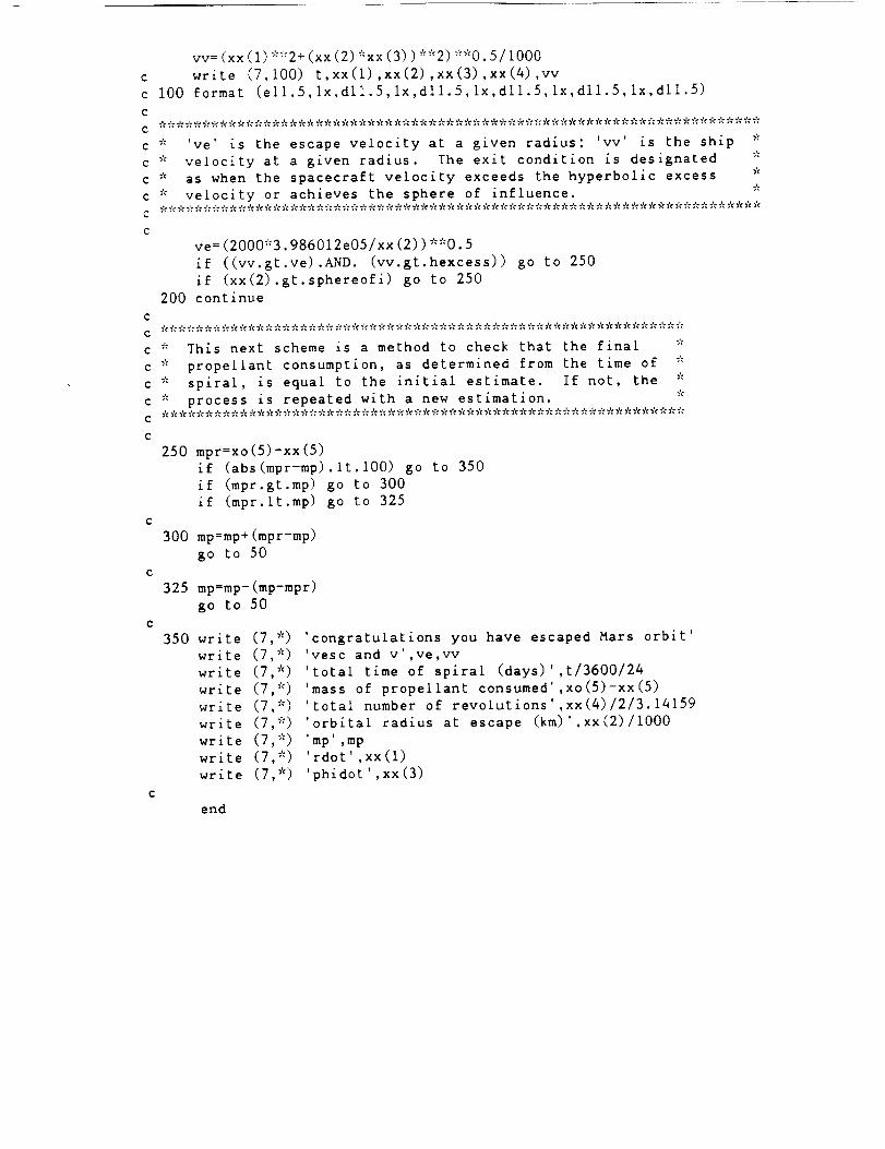
vv = (xx (i) *_'_2+ (xx (2) *xx (3))**2) **0.5/1000
c write (7,100) t,xx(1),xx(2),xx(3),xx(4),vv
c I00 format (ell.5,1x,dll.5,1x,dll.5,1x,dll.5,1x,dll.5,1x,dll.5)
c
c
c * 've' is the escape velocity at a given radius: 'vv' is the ship _'_
c * velocity at a given radius. The exit condition is designated *
c * as when the spacecraft velocity exceeds the hyperbolic excess
c * velocity or achieves the sphere of influence. *
c
ve = (2000*3.986012e05/xx (2))**0.5
if ((vv.gt.ve).AND. (vv.gt.hexcess)) go to 250
if (xx(2).gt.sphereofi) go to 250
200 continue
c
o
c * This next scheme is a method to check that the final _:
c * propellant consumption, as determined from the time of *
c * spiral, is equal to the initial estimate. If not, the *
c * process is repeated with a new estimation. *
250 mpr:xo(5)-xx(5)
if (abs(mpr-mp).It.100) go to 350
if (mpr.gt.mp) go to 300
if (mpr.lt.mp) go to 325
300 mp=mp+(mpr-mp)
go to 50
325 mp:mp-(mp-mpr)
go to 50
350 wr
wr
wr_te (7
wrzte (7
wr_te (7
write (7
write (7
write (7
write (7
te (7,*) 'congratulations you have escaped Mars orbit'
zte (7.*) 'vesc and v',ve,vv
*) 'total time of spiral (days)',t/3600/24
*) 'mass of propellant consumed',xo(5)-xx(5)
*) 'total number of revolutions',xx(4)/2/3.14159
*) 'orbital radius at escape (km)',xx(2)/1000
*) 'mp',mp
*) 'rdot',xx(1)
*) 'phidot',xx(3)
end
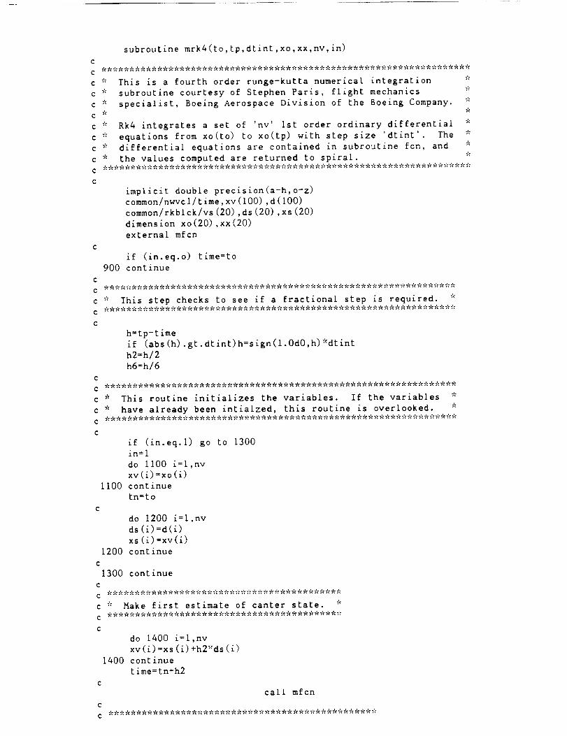
c
c
c "_
c
C "_'c
C _'_
C _'_
c
c
c
c
subroutine mrk4(to,tp,dtint,xo,xx,nv,in)
This is a fourth order runge-kutta numerical integration
subroutine courtesy of Stephen Paris, flight mechanics
specialist, Boeing Aerospace Division of the Boeing Company.
Rk4 integrates a set of 'nv' Ist order ordinary differential
equations from xo(to) to xo(tp) with step size 'dtint' The
* differential equations are contained in subroutine fcn, and
* the values computed are returned to spiral.
implicit double precision(a-h,o-z)
common/nwvcl/time,xv(lOO),d(lO0)
common/rkblck/vs(20),ds(20),xs(20)
dimension xo(20),xx(20)
external mfcn
if (in.eq.o) time=to
900 continue
c
c * This step checks to see if a fractional step is required. *
c
c
c
c
c
c
h=tp-time
if (abs(h).gt.dtint)h=sign(l.0d0,h)_:dtint
h2=h/2
h6=h/6
* This routine initializes the variables. If the variables *
* have already been intialzed, this routine is overlooked. _
if (in.eq.l) go to 1300
in=1
do ii00 i=l,nv
xv(i)=xo (i)ii00 continue
in=to
do 1200 i=l,nv
ds (i)=d(i)
xs (i) =xv (i)
1200 continue
c
1300 continue
c
C *******************************************
c * Make first estimate of canter state. _=
c
c
do 1400 i=l,nv
xv (i) =xs (i) +h2*ds (1)
1400 continue
time=tn+h2
c

c
c
c
_"_ Revise estimate with derivative at center. _:
do 1600 i=l,nv
vs(i)=ds(i)+2.00*d(i)
xv(i)=xs(i)+h2*d(i)
1600 continue
ccall mfcn
='= Make first estimate of state at end of step. *
do 1800 i=l,nv
vs(i)=vs(i)+2.00*d(i)
xv(i)=xs(i)+h*d(i)
1800 continue
time=tn+h
call mfcn
c
do 1820 i=l,nv
ds (i) =d(i)
1820 continue
c
do 1810 i=l,nv
vss=h6 * (vs (i)+d(i))
xs (1)=xs (i)+vss
xv(i) :xs (i)1810 continue
call mfcn
c
c * Update the time for the next step.****************************************
tn=t ime
_ End: copy state to 'xx' *
if(time.ne.tp) go to 900
do 2000 i=l,nv
xx (i) =xv(1)
2000 continue
c
return
end
c
c * Final estimate based on derivative at center and both ends, _':
c * with double weight on the center estimates. *_'_ _'_ _'¢ _'¢ _': _': _ • _'= _'¢ ";':_'¢ _': ";% _'¢ _'¢ _'¢ _'¢ _'t _'t ";'¢_': _'¢ ,_¢ _'¢ _'¢ _'¢ _'¢ _'¢ "]¢ _ _'¢ _'¢ _'t "/¢ _': ";'t_'¢ _'¢ _'¢"/¢ ";'¢_'¢ _'¢ _ ";'¢ _'¢ _'¢ ";'_ _'_ _'¢ _'¢ _'¢ _': "/¢ _'t _'¢ _'¢ _¢"_'t _ _'¢ _'¢ _'¢ _'¢ _'_

subroutine mfcn
C
c * Fcn is the derivative evaluation routine for runge-kutta *
c * numerical integration routine. The values of t,x, and d *
c * are passed thru the common block. _':
C * *
The differential equations are of the following form:
d(n) = dx(n)/dt = f(x(1), x(2) .... x(nv) ).
C
implicit double precision (a-h,o-z)
common/nwvcl/t, x (i00) ,d (I00)
C
The constants defined below are as follows: *
c 7'= g = acceleration due to gravity at the planet's surface *
c * ro = radius of the planet *
c _'_ f = the thrust of the spacecraft *
c * pmdot = propellant mass flow rate *
c * rs = radius of the sun _:
c * dsm = distance from the center of the sun to the center *
c * of Mars *
C
g=3. 768
ro=3380000
rs =696000000
dsm=2.4e I 1
c
C W'_* _¢_;_cW`f¢.f_`f_._._C7_f_.f¢`_=_f¢_c_7_7_¢_%;_¢_*7%_W9:_W_9¢_¢_C 7'c _'¢* 7'¢'f_";'c'7'c'* 7_-'f¢',,'¢ _';''r/¢ 'i_''!_" 7%7'¢9= ='C7':
c * The following sequence of steps incorporates the effect *
c * of the shadow of the planet. This analysis is clarified *
c * within the text of the corresponding appendix. *
C
s=x(4)
dm=ro*dsm/(rs-ro)
if (x(2).gt.dm) go to 300
beta=ro/dm
gamma=atan ((dm-x (2))/x (2) *tan (beta))
if (s.lt.6.283) go to 200
rev=S1213.14159
s=s-int(rev)*2*3.14159
i00 continue
200 if (s.lt.(3.14159-gamma)) go to 300
if (s.gt.(3.14159+gamma)) go to 300
f=0
pmdot=0
go to 400
300 f=40
pmdot=-.001638001638
C
C ************************************************************************
c * State Dictionary: *
c * r = radius of the spacecraft's orbit *
c * phi = true anomaly measured from initiation of manuever *
c * m = mass of the spacecraft *
c * x(1) : dr/dt *= * x(2) : r _:
c * x(3) : d(phi)/dt *
c * x(4) = phi *
c * ×(5) : m _':
c
c
400 d (i) =f*x (i)/x (5) / (x (I)*'2+ (x (2)*x (3) ) *'2) **0. 5+x (2) *x (3) **2-
ig_'=ro_':*2/x (2) **2
d(2)=x(1)
d (3) =f*x (3)/x (5) / (x (I) **2+ (x (2) *x (3)) **2) **0.5-2"x (i) ='=x(3)/x (2)
d(4):x (3)
d (5) =pmdot
return
end