Embed Size (px)
Citation preview
,D-R128 267 GENERAL GUIDELINES FOR THE MITIGATION OF NUCLEAR NEAPON i/I
EFFECTS ON FIBER..CU) HARRY DIAMOND LABS ADEIPHI MD
UNCLRSSFIEDR JREYZER ET AL. APR 33 HDL-SR-83-4 FG1/. I
111 1.0 3 2
lu U. 12.11.8
1 125 1.,4 1 1.6
MICROCOPY RESOLUTION TEST CHARTpNATIONAL BUREAU OF STANDARDS] 963-A
.~~~7 .. .....If.
A~~U.S Armyne forooic tResearctioIVot on Devloprn Optcmomuncaio
throu~t, the DseifnSelected Desig
Adlh-MI 08
~ V
4 .- 05
'*'''I 05
rrr -rw-t-v
.4 - --
Ii
F .'a&-
4~ b ~6
fl
27:.4.--
* V&~.C9~'4 -~
4. 4.
~td <t~~t.ti*it~
~.- £-*... ~- ~"N4'-
At -etZ&
us .. sin.m stanwt'~~a.t
-' 4),*~ ~ i~N uS SINUS a
44%
. >F ~
* --
.~ Jr 4n't
ci
1
*444 4
UNCLASSIFIEDSECURITY CLASSIFICATION OF THIS PAGE (Whien Dete Ent.red)
REPORT DOCUMENTATION PAGE BEFORE COMPLETING FORM
I. REPORT NUMBER 2. GOVT ACCESSION NO. 3. RECIPIENT'S CATALOG NUMBER
HDL-SR-83-4 4 ,1 ... ,. 4. TITLE (od Subtitle) 5. TYPE OF REPORT A PERIOD COVERED
,- General Guidelines for the Mitigation of Nuclear Weapon Effects Special Reporton Fiber Optic Communication Systems through the use ofSelected Design Practices 6. PERFORMING ORG. REPORT NUMBER
7. AUTHOR(e) S. CONTRACT OR GRANT NUMBER(*)
Ronald J. ReyzerStewart ShareJohn F. Sweton
9. PERFORMING ORGANIZATION NAME AND ADDRESS 10. PROGRAM ELEMENT. PROJECT, TASK
Harry Diamond Laboratories AREA & WORK UNIT NUMBERS
2800 Powder Mill Road Program Ele: 62715Adelphi, Maryland 20783
I1. CONTROLLING OFFICE NAME AND ADDRESS 12. REPORT DATE
Defense Communications Agency April 1983Attn: NCS-TS 13. NUMBER OF PAGES
National Communications System 25
Office of Technology and Standards 15. SECUR CLASS. (of this repor)
Washington, DC 20305 UNCLASSIFIED
14. MONITORING AGENCY NAME & AOORESS(II dlllerent from Controlling Orfice) 15s. DECLASSIFICATION/DOWNGRADING
SCHEDULE
*, I. DISTRIBUTION STATEMENT (of this Report)
Approved for public release; distribution unlimited.
17. DISTRIBUTION STATEMENT (of the abstrac titered In Block 20. It different frm Report)
16. SUPPLEMENTARY NOTES
DRCMS Code: 33126KPRON: WS3-8301WSA9DA: E31300HDL Project: E313E3
IS. KEY WORDS (Continue an reverse OdeIt neceesay nd Identify by block number)
Nuclear weapon effectsEMPFiber optic communication systems
26. ABSTUACT (ctrtnoet so reverw f N neceeaery mu Identify by block numbet)%'
This report provides guidelines for the design and installation of a fiber optic communication system toimprove the tolerance of that system to a nuclear environment. These guidelines, if incorporated, canprotect a significant portion of the national fiber optic communication system resources that mightotherwise be destroyed.
DD JA 1473 EDI ON OF I OV 65 IS OSOLETE,, UNCLASSIFIED
1 SECUITY CLASSIFICATION OF THIS PAGE (When Dot& Entered)
. . . . .
CONTENTSPage
1. PURPOSE . . . . .......................... ............ ... ......... 5
2. BACKGROUND ................ * .. ........... 5
2.1 Electromagnetic Pulse Effect .................... ................. 52.2 Blast/Shock, Initial Radiation, Residual Radiation, and
Thermal Effect ............. ...... 6
2.3 Above-Ground Equipment, Above-Ground Fiber Optics--Height ofBurst to Maximize Blast and Shock ............................. 6
2.4 Above-Ground Equipment, Above-Ground Fiber Optic Cable--Height
of Burst to Maximize Fallout (Surface Burst) ................... 72.5 Buried Fiber Optics with Above-Ground Transmitters, Repeaters,p and Office Equipment .......................................... 7
3. EMP GUIDELINE ............................. 8
- 3.1 Reduction of Interaction Area ................................... 9. 3.2 Zonal Philosophy .......................................... ..... 9
3.3 Application of Zonal Philosophy ............................... 113.4 Design Practice for Achieving Zonal Protection ................. 11
3.5 Specific Guidance for EMP Protection of Fiber Optic Systems ..... 18
4. GUIDELINES FOR LOW-ALTITUDE NUCLEAR ENVIRONMENTS ..................... 19
4.1 Initial Nuclear Radiation and Residual Radiation ................ 19
4.2 Electromagnetic Pulse .......... . .. ... . 204.3 System-Generated Electromagnetic Pulse ........................ 204.4 Blast.... .......................... 204o5 Thermal Radiation ........................ 21
4.6 Implementing Guidelines ....... ... ............... *..... ... 21
5* SUMMARY ,0.,. .. ...................... 21
LITERATURE CITED ................................ 22
DISTRIBUTION ... 23
FIGURES
1. Typical defense switched network facility 0.................... - . -. 0 1*0
2. Environmental zones in complex facility ............. 0.00 ..... 11
3. Connections that preserve shielding integrity and compromisethe shield .............................................. 15
4. EMP clamping devices--V-I characteristics ................... 16 0
TABLE
1. Comparison of Protection Devices ..................................... 16
Avr2>>1> I ' Codes
3 Av Il n nd/or
Di Special
- ) ! i . ) .: . .. . - . .
I. PURPOSE
This report provides guidelines to improve the tolerance of a fiber opticcommunications system (FOCS) to a nuclear environment. These guidelines, ifincorporated, can protect a significant part of the national FOCS resources
that otherwise might be destroyed.
2. BACKGROUND
A fiber optic communication system consists of a transmitter, receiver,repeater, network of fiber optic cables, and the power that is ne-ded for thesystem to operate. Some or all of these components may be mounted above orbelow ground. The hostile nuclear weapon environments include blast andshock, thermal radiation, initial radiation, residual radiation, andelectromagnetic pulse (EMP). All these environments can be expected within a
K localized region of space surrounding a surface or an atmospheric nuclearburst. For a nuclear burst above the earth's atmosphere (exoatmospheric orhigh altitude), only the EMP effect will be hostile to ground-based FOCS.Before we discuss the specific measures that can be designed to protect FOCSfrom these nuclear environments, it is wise to first discuss the environmentsthemselves.
2.1 Electromagnetic Pulse Effect
Surface and air nuclear bursts threaten ground-based FOCS through anumber of effects, one of which is EMP; high-altitude nuclear bursts are athreat only because of EMP. Guidelines for protection from E4P are includedin section 3 of this report. There are basic differences between the EMPeffect from a high-altitude nuclear burst and that from a surface or low-altitude nuclear burst. The high-altitude EMP will cover large areas of theU.S. from a single event; low-altitude EIP will affect only equipment in theimmediate vicinity of the burst. Of course, high-level transients generatedclose to a low-altitude burst will propagate down power lines and otherconductors and will need to be dealt with at greater distances than thoseassociated with the source region.
Accompanying the low-altitude and surface burst DIP will be initial
radiation, which can cause its own EMP within metal enclosures, and time-varying air conductivity, which will change the DIP coupling to conductors byproviding an additional current driver that is proportional to the level of
"" conductivity times the level of the incident electric field. There are otherimportant differences between EMP effects at varying altitudes. For example,the EMP field close to a nuclear event will not be planar in nature and willnot behave like a far-field EMP. Also, although EMP from the low-altitude andsurface burst exists over a relatively small area, the energy contained in thepulse is usually much greater. The peak amplitude of the E field (except very
5
!.
close in to the burst) is about the same for both, but the pulse width due tothe low-altitude EMP may be 1000 times longer. Because of these differencesand because of the difficulty in analyzing and simulating the low-altitude EMP
effects there remain many questions regarding the effectiveness of EMP
hardening practices required to protect systems close to a low-altitudeevent. Nonetheless, the practices recommended for high-altitude EMP hardeningwill &lso provide a great deal of protection for low-altitude EMP problems.The brief specific guidance in section 4.2 is included as a reminder of the
E4P problem and is intended to recall the more detailed guidance in section 3.
2.2 Blast/Shock, Initial Radiation, Residual Radiation, andThermal Effect
In low-altitude and surface detonations of nuclear devices, all the
effects previously described are of potential concern. Factors such as thewarhead yield, type, and height of burst will determine the magnitude of eacheffect.
The effect of each of these environments depends on the specific
design, installation, and component selection of the FOCS. Because of this,it is not possible to say, except in very general terms, the relativesignificance of each environment. Such significance is important, however,from a hardening philosophy standpoint, since it would make little sense to
- harden a specific system to withstand blast overpressure consistent with a 1-MT surface burst at a distance of 16 km (10 mi) only to find that higher level
". residual radiation resulted in permanent darkening of all fiber links to adistance of hundreds of miles from the burst. A directed hardening effortwould try to establish hardening consistency (balanced hardening) for all
.- effects so that if a FOCS failed due to a specific nuclear environment, itwould be close to failing from the other environments as well. As an example,consider the effects of a 1-MT fission-type nuclear weapon on a few examples
of FOCS deployments.
Glasstonel identifies the magnitude of the effects of a 1-MT nuclearweapon (exclusive of the E4P effect).
2.3 Above-Ground Equipment, Above-Ground Fiber Optics--Height of Burst toMaximize Blast and Shock
If the FOCS is configured so that the transmitter and receiver aremounted in typical buildings, and if the repeaters and fiber optic links aremounted on telephone poles, then the predicted blast and shock effects wouldproduce significant system destruction out to a radius of about 8000 m (5mi). At 8000 m from the burst, a total initial radiation dose of less than 1rad with a rate of 107 rads/s would be expected. Neither 1 rad of initialradiation nor a dose rate of 107 rads/s would be expected to do significant
ISamuel Glasstone, The Effects of Nuclear Weapons, published jointly by theDepartment of Defense and the Department of Energy, Washington, DC (1977).
6
• n " , ,, .,- . 2 - .'., '. . ". ' .- . - "--."- "- •r"r"-" ' - .
permanent damage to a typical FOCS. However, a low yield weapon (e.g.,150 kT) would result in a dose rate of 2 x 10⁹ rads/s at the same blast over-pressure. This dose rate is enough to permanently damage FOCS electronics.
2.4 Above-Ground Equipment, Above-Ground Fiber Optic Cable--Height ofBurst to Maximize Fallout (Surface Burst)
The fallout from a 1-MT surface burst is a function of time,distance, weather conditions, and wind. At 161,000 m (100 mi) downwind fromthe burst, a total radiation dose of 30,000 rads within the first 6 hr would
Inot be unreasonable. This level of radiation is enough to permanently darkenexposed optic fibers.* Its effect on system performance will depend upon thesafety margin built into the system design. For above-ground systems this ispotentially the most serious threat in terms of both range and extent of
S""damage.
Thermal radiation from a 1-MT atmospheric burst would deliver about30 cal/cm2 at 8000 m (5 mi). At this range, some damage to the fiber opticcable covers would be expected, but it is unlikely that this damage wouldresult in signal degradation.
The source-region (low-altitude, surface burst) EMP should beconsidered significant to a radius of 8000 m. At this range, the E field isprimarily vertically polarized and slowly rising and would probably coupleless to vertical conductors than would the vertically polarized, fast-rising,high-altitude EMP environment.
It can be seen that within 8000 m of a 1-MT fission-type detonation,above-ground FOCS can be damaged by blast/shock, EMP, and to some extentthermal environments.
Potentially more serious is the threat to FOCS from residualradiation which can extend downwind of the burst for a hundred miles or more.
2.5 Buried Fiber Optics with Above-Ground Transmitters, Repeaters, andOffice Equipmentt
The fiber optic links are assumed to be buried to a depth of 1 mbelow the earth's surface.
Damage from the blast and shock (optimized height of burst) wouldmost likely be contained within 5000 m (3 mi) of ground zero.
The attenuation of gamma rays through I m of earth is about 1000. At- 5000 m, the initial radiation dose is about 5 rads. Thus, at 3 mi the initial
*This level is also enough to permanently damage the electronics of FOCS.
tit is more realistic to assume that cransmitters/receivers and officeequipment are above ground than to assume a completely buried system.
7
radiation dose from a 1-MT burst through 1 m of earth would be no more than. 1/200 rad. The dose rate at this range is about 5 x 10⁸ rads/s, and at 1-m
depth the dose rate would be reduced to about 5 x 10⁵ rads/s. Above-groundelectronics (especially in the repeater circuit) can sustain permanent damageand/or "latch-up" at dose rates of 5 x 10⁸ rads/s.
7I
It is unlikely that the buried fibers would be permanently darkeneddue to these levels. However, the exposed fibers exiting the ground would
* probably suffer permanent darkening to some extent. Also, the electronicsexposed to these levels would be susceptible to damage. The overall effect on
.- the FOCS would be system-dependent.
Downwind of the 1-MT surface burst, a total dose of residualradiation of 30,000 rads is possible at a range of 161,000 m (100 mi). For
.- buried fibers, the level of exposure would be 30 rads. This is probablyenough to permanently darken the fiber. As before, the portions of the fiberwhich exit the ground to go to repeaters and office equipment could sufferappreciable darkening and the electronics in above-ground installations couldsuffer permanent damage. Together, these effects could cause transmissionproblems over rather long sections of FOCS.
Also, the shallow burying of conductors will not add significant. protection against EMP. Thus, if the buried fiber optics contain conductors--, such as order wires or power wires--these conductors will be strongly excited. by the horizontal EMP from an exoatmospheric burst. Possible damage will," depend on hardening features incorporated in the design and the sensitivity of*the specific electronics.
* 3. EMP GUIDELINE
Transient upset is not a consideration for the purposes of this report;therefore, the object is to minimize damage to the system.
High-altitude, low-altitude, and surface nuclear bursts will generate anEMP that will be coupled to power lines feeding repeaters, and otherelectronic components of the FOCS, as well as to any metallic strength
'* members, metallic shields, and copper pairs that are incorporated into theoptical fiber cable itself.
Although the D4P fields in the air are greater than the fields in theearth (for the higher frequencies of interest), the fields in the earth within
. a few meters of the air/earth interface are large enough to be of significant- consequence. Therefore, buried cables should not be considered hard to EMP
effects. This is true for both high-altitude and low-altitude nuclear eventsor for surface nuclear events.
8
Sections 3.1 and 3.4 have been extracted from a Naval Ocean System Centerreport.2 Section 3.2 has been extracted from Harry Diamond Laboratories HDL-SR-82-2. 3
Over the years, a number of engineering design practices have beendeveloped to protect ground systems from EMP. 4-6 The basic protectionphilosophy behind the design practices is that they minimize, to as high adegree as possible, the propagation of external incident energy into sensitiveelectronics in enclosure interiors. Four generic categories of designpractices are (1) reduction of interaction area or volume (EMP couplingreduction), (2) shielding and grounding, (3) protection of zone interface, and(4) designing for tolerance to transients. Since we are concerned here with
* reconstituting a system after an event, the fourth category--designing fortolerance to transients--will not be discussed.
3.1 Reduction of Interaction Area
The amount of energy coupled onto conducting system elements exposed
to EMP is approximately proportional to their length and to the area theseelements make in combination with the surrounding ground planes. The groundplane is typically defined by the earth itself for external conductors. Thisdesign practice category seeks to minimize the length or area of theconducting elements. Simple geometrical rearrangement of the facility duringdesign can often result in fewer or shorter cable runs and in less favorablecoupling geometries for wire-to-wire coupling and EMP field coupling. Runningconductors next to ground planes minimizes pickup loops. The use of twistedpair cables, along with balanced sending and receiving circuits, can result ina cancellation of EMP-induced common transients. The EMP energy may beprevented from coupling into facilities by replacement of conductingstructures with nonconductors and by substitution of optic links forcommunication cable elements.
3.2 Zonal Philosophy
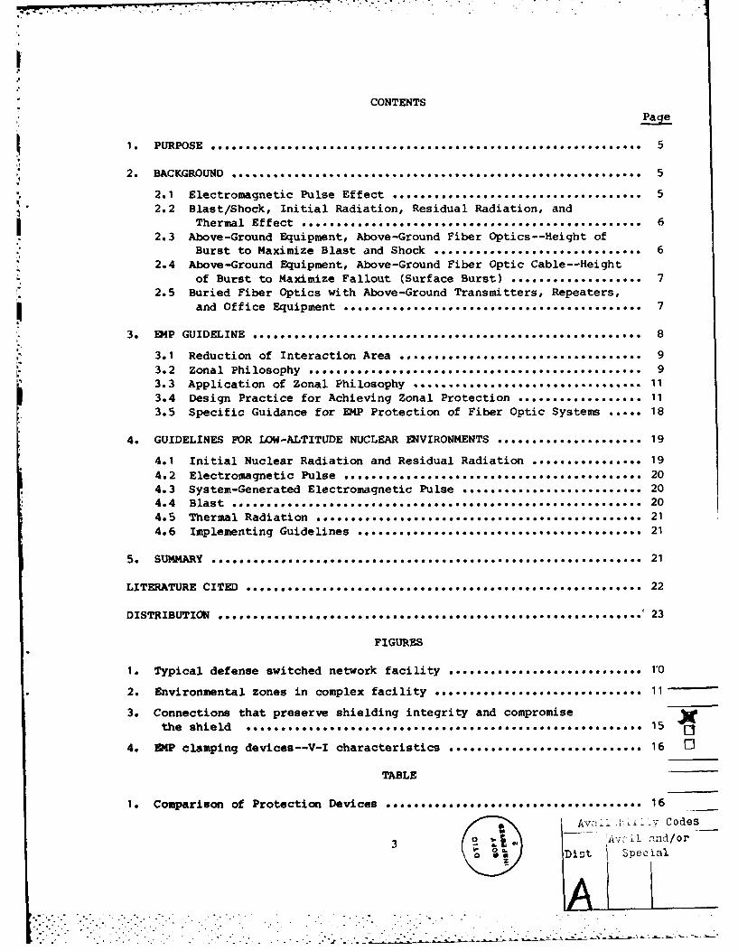
Communication facilities (see fig. 1) contain several regions of
electromagnetic environment separated by barriers such as building walls andcabinet shields. For example, the building walls separate the harsh externalenvironment from the less harsh room environment, and the equipment cabinetseparates the room environment from the small-signal environment inside thecabinet. Within the cabinet, there may be a third level of shielding to
2EMp Engineering and Design Principles, Bell Laboratories (1975).3p. R. Tryhus, Ground Based Systems EMP Design Handbook, MRCH/2-M-211,
Mission Research Corporation (August 1977).4EMP Engineering Practices Handbook, SRI, NATO File No. 1460-2 (October
1977).5R. A. Greenwall, EMP Hardening of Tactical Ground Systems Through Electro-
Optical Techniques: Design Guidelines, Naval Ocean System Center TechnicalRetort 645 (20 December 1980).
J. R. Miletta et al, Defense Switched Network Design Practices for
Protection Against High-Altitude Electromagnetic Pulse, Harry DiamondLaboratories HDL-SR-82-2 (July 1982).
9
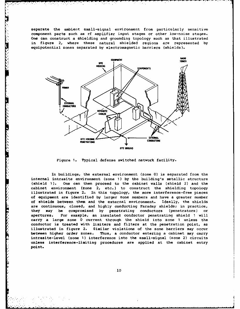
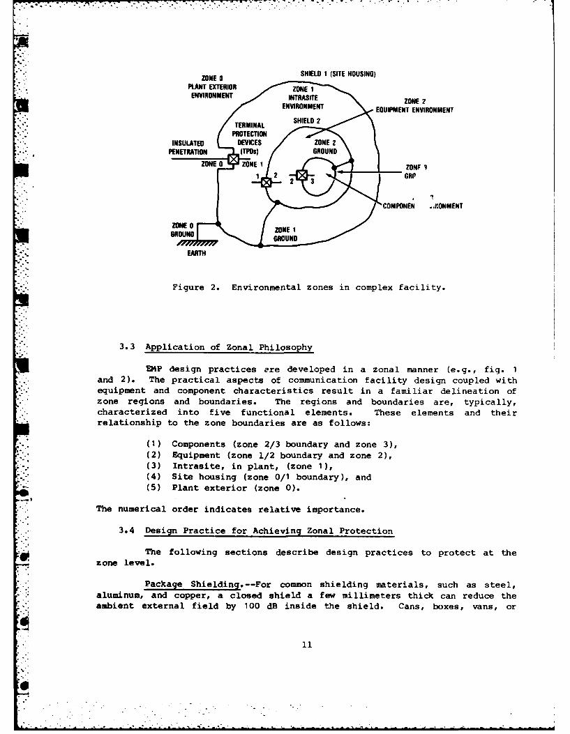
separate the ambient small-signal environment from particularly sensitive*component parts such as rf amplifier input stages or other low-noise stages.. One can construct a shielding and grounding topology such as that illustrated
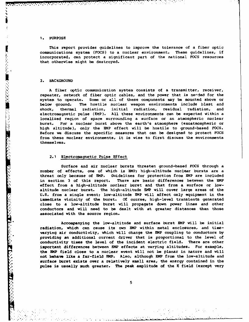
in figure 2, where these natural shielded regions are represented byequipotential zones separated by electromagnetic barriers (shields).
EOUIP IT RADIO,."i ' ECOMPPNENT
TONSITE
HOUSINGCOMPONENTS
"- SITEHOUEXTERNAL
'-PENETRATION$i CONDUCTORS
SITE GROUND
Figure 1. Typical defense switched network facility.
In buildings, the external environment (zone 0) is separated from theinternal intrasite environment (zone 1) by the building's metallic structure(shield 1). One can then proceed to the cabinet walls (shield 2) and the
" cabinet environment (zone 2, etc.) to construct the shielding topologyillustrated in figure 2. In this topology, the more interference-free piecesof equipment are identified by larger zone numbers and have a greater numberof shields between them and the external environment. Ideally, the shieldsare continuous, closed, and highly conducting Faraday shields; in practice,they may be compromised by penetrating conductors (penetrators) or
- apertures. For example, an insulated conductor penetrating shield 1 will* carry a large zone 0 current through the shield into zone 1 unless the
conductor is treated with limiters and filters at the penetration point, asillustrated in figure 2. Similar violations of the zone barriers may occurbetween higher order zones. Thus, a conductor entering a cabinet may carry
* intrasite-level (zone 1) interference into the small-signal (zone 2) circuits- unless interference-limiting procedures are applied at the cabinet entry
point.
10
SHIELD 1 (SITE HOUSING)" - ZONE 0PLANT EXTERIORENVIRONMENT
ZONE 2ENVIRONMENT EQUIPMENT ENVIRONMENT-TERMINAL
PROTECTION
INSULATED DEVICES ZNPENETRATION (TPOS) GON
.ZONE 0 ZONE 1 ZONF I'1 2 2 3GRP
COMPONEN .ONMENTSZONE 0 ZOE
GROUND
EARTH
Figure 2. Environmental zones in complex facility.
3.3 Application of Zonal Philosophy
E14P design practices are developed in a zonal manner (e.g., fig. 1and 2). The practical aspects of communication facility design coupled withequipment and component characteristics result in a familiar delineation ofzone regions and boundaries. The regions and boundaries are, typically,characterized into five functional elements. These elements and theirrelationship to the zone boundaries are as follows:
(1) Components (zone 2/3 boundary and zone 3),(2) Equipment (zone 1/2 boundary and zone 2),(3) Intrasite, in plant, (zone 1),(4) Site housing (zone 0/1 boundary), and(5) Plant exterior (zone 0).
* The numerical order indicates relative importance.
* .**,3.4 Design Practice for Achieving Zonal Protection
The following sections describe design practices to protect at thezone level.
Package Shielding.--For common shielding materials, such as steel,aluminum, and copper, a closed shield a few millimeters thick can reduce theambient external field by 100 dB inside the shield. Cans, boxes, vans, or
- 1 1
other shielding enclosuces take many forms. The ideal, continuously weldedenclosur- is almost never used because the equipment and personnel enclosedbecome inaccessible. In practice, the performance of a real shield is usuallynot governed by the thickness, permeability, or conductivity of materials (asthese are usually sufficient), but rather by the defects that exist in theshield. These defects include the presence of minute apertures arising fromconstruction, or large apertures, such as vents, doors, and seams, as well as
* various types of penetration (e.g., cables and pipes through the shield).Various techniques for maintaining shielding integrity are needed because of
" "these obviously necessary penetrations.
*The mechanical assembly of a shield must specify clean metal-to-metal
mating surfaces. Good contact between the surfaces should be assured by theuse of either a continuous bond or, at least, set screws or rivets at closeintervals. The maximum allowable distance between fasteners is 2 to 4 in.(-50 to ~100 mm). Many metallic oxides, particularly aluminum oxide, arenonconductive. In addition, the finishes commonly applied to metals, such asthe iridite or anodizing applied to aluminum or the cadmium plating applied toiron and steel, are less conductive than the metals themselves. Care shouldbe taken to assure that a clean, highly conductive surface exists and can be
- * maintained at each metal-to-metal contact point.
When openings are necessary for airflow, various forms of screens
should be used to break the large opening into a series of small openingswhich act as waveguides below cutoff. To be m 3t effective, the intersectionsbetween openings must be fused. Three commoniy used devices are honeycomb,perforated sheet metal, and wire mesh screen. Honeycomb iq usually the mosteffective for large openings and offers the additional advantage of lowresistance to airflow. Wire mesh screen is useful when an opening requiresshielding, yet visibility through the aperture must be maintained. The wiremesh is also useful for some shielding of vent holes that are too small to
• *. accommodate a honeycomb shield.
* Openings which require visibility are often part of display devices,
such as meters, display screens, lamps, etc. Large display apertures requiredfor oscilloscope screens or plasma display panels generally need special
shielding. At times it is necessary to use see-through wire mesh screer infront of the display panel in conjunction with a solid metal shield behind thepanel.
To allow for servicing, most shielding equipment has a bolted coverof some kind. Spacing between fasteners must be closer for materials withthinner covers, because the mated surfaces buckle between the fasteners. ForEMP shielding protection, gasketing ensures metallic contact. Any one ofseveral types of conductive gaskets may be used to close the opening, but itmust be thick enough and soft enough to fill in all irregularities. Wherecovers are to be removed and replaced, the gasket must be able to return toits original shape, or a new gasket must be used. The contact pressure shouldbe high enough to make adequate contact, even when there is a nonconductingcorrosion present. In most cases, any of a number of gasketing materials willelectrically satisfy the requirements. However, EMP shielding must be
12
maintained during equipment use. Thus, it is important for the designer toconsider mechanical suitability in specifying the overall ERP hardness.
Some shielded openings, such as doorways and hatches, are frequentlyopened and closed. In these cases, compression-type gasketing often is notsatisfactory. An alternative gasketing arrangement is conductive fingerstock, which affords a self-cleaning metal-to-metal seal between the doorwayand the enclosure. The finger stock must be springy so that good mechanicalcontact is maintained throughout use. A beryllium copper alloy is often usedto combine good spring action with high conductivity.
Conductive paints or epoxies can sometimes be used when shielding isnot very critical. Their use for E4P shielding is very limited because theirvolume resistivities are usually on the order of 1000 times higher thancopper, greatly limiting the amount of shielding available. Another greatdisadvantage is that most of the best conductive paints must be baked at over1000 C to get the best electrical characteristics. Baking the enclosure isobviously not feasible because of the electronic gear inside.
Rectangular structures usually are approximated by cylinders,spheres, or parallel plate enclosures to solve shielding problems, if it isrecognized that the solutions are inaccurate in near corners. The timedependence of the interior field is not changed, but the amplitude of thefield can increase significantly at a corner. In the corners of rectangularboxes there is a concentration of current, which causes a larger magneticfield than predicted by spherical models. The field will double at r =(0.25)XO, where X. is half of the longest box dimension and r is the distancefrom the corner. This buildup continues as the corner is approached and willbe 10 times at r = (0.06)XO . Thus, it is important to avoid placingmagnetically sensitive devices or potential loop antennas near box corners.Rounding the corner is a useful preventive technique. Apertures and otherdiscontinuities in the solid shell are also regions of locally high fields.
Cable Shielding.--Overall shields must be placed on cable which mightbe directly exposed to EMP or internal E4P (IEMP). It is useless to closeapertures in package walls if transients are then allowed to flow freely onpenetrating cables. The best cable shields are solid materials, such as rigidconduit or pipe. Such shields should be used where the weight and/or assemblypenalty is not excessive. Doubled braided shields can be highly acceptableshielding for cables if the layers of braid are of the right weave, are ofgood conductivity, and are separated by a dielectric layer. The jacket isusually insulated and minimally affects the shielding properties of thecable. Unlike a solid shield, a braided shield offers many tiny apertures forelectromagnetic coupling to the interior signal wires.
The signals induced on sensitive signal wires can be further reducedif the wires are shielded individually and placed in the center of the corebundle with low-impedance lines (e.g., power ground, etc.) on the periphery ofthe core bundle. Cable constructions such as this effectively have fourlevels of shielding. As with package shields, the continuity of shields mustbe maintained at the back shells of interface connectors. In particular, the
13
overall shield(s) must have circumferentially complete termination to theconnectors. Pigtail terminations do not provide acceptable continuity.Special radio frequency interference/electromagnetic interference (rfi/emi)protective connector back shells should be used where possible.
Grounding.--Proper ground schemes help reduce system vulnerabilitiesto transient ground currents and maintain overall shielding integrity. It isoften difficult to separate the subjects of shielding and grounding. Inpractice, several levels of shielding and grounding may be used. The systemfor facilities and equipment consists of two distinct elements: exteriorgrounding and zone grounding. The exterior ground attempts, in a field-significant way, to connect to the large, but poot, conductor which covers theearth's surface. This ground is particularly important, since it serves as asink to which shield and penetration currents are diverted. The externalground should have a low impedance and should be distributed for easyconnection and minimal earth gradients across the facility. The ring groundmeets all these requirements and is a counterpart of the zone grounding,discussed next. Zone grounding often consists of a building or overallenclosure shield with its internal electrical grounding system, a cabinetshield with its internal electronics grounding system, and, perhaps, shieldedcomponents within the cabinet.
At each level the shield guards against the external environment, andthe grounding controls potentials from internal sources.
The equipotential region within zones can be disturbed by internalsources or charge displacements. Thus, all older sources and internalconductors and structures, such as equipment enclosures, cable trays, shields,and conduits that are not intentionally at a potential different from theshield potential, should be connected to each other and to the inside surfaceof the shield. This common "grounding" approach, which includes even theoutside of the shield enclosing the next inward zone, is used for eachfacility zone. This grounding scheme is known as regional single-point zonegrounding and results in an overall internal ground tree.
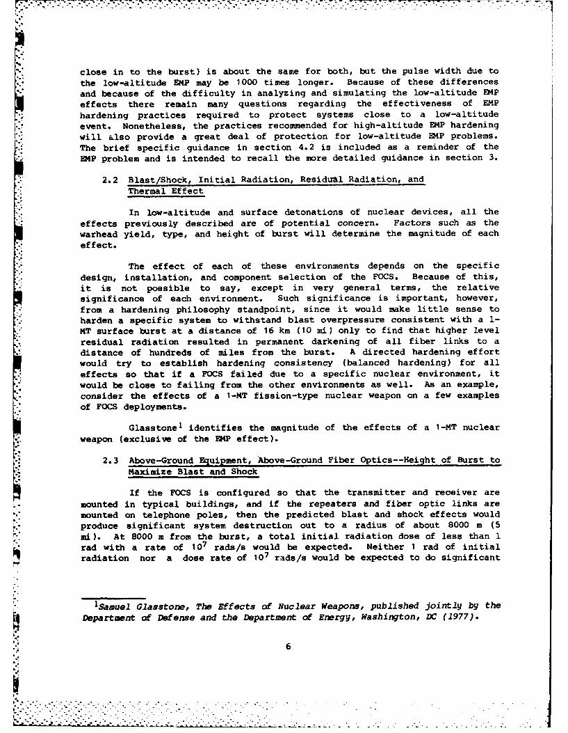
An important rule of effective shielding and grounding practice isthat topologically grounding conductors should never penetrate shieldsurfaces.
Inherent in the theory of electrodynamic shields is the fact that" current in conductors attached to a shield flows predominantly on the surface
to which the conductor is attached. This phenomenon is a manifestation of theskin effect in conductors. The skin effect permits currents on conductors
*: outside the shield to be diverted to the outside surface of the shield.
Figure 3 shows several examples of correctly applied shielding, alongwith some common violations of correct shielding practice. Each of thoseviolations permits the harsh currents on the outside conductors to flow intothe protected zone shield. Filters and surge arrestors behave like any otherconnection of a penetration to the shield; that is, they divert harsh
14r- .
interference currents to the outside surface of the shield, thereby preventingthese currents from entering the protected region. Because power and signalcarrying conductors cannot be continuously connected to the shield, they mustbe connected momentarily (when a certain threshold is exceeded) or connectedonly at frequencies not used for power or signals (i.e., through a filter).In any case, the diverted interference currents must flow to the outsidesurface of the shield, as illustrated in figure 3(c), if shield integrity isto be preserved.
OUTSIDE INSIDE
EXTERNAL?GROUND INTERNAL
GROUND
RIGHT WRONG
(a) GROUNDING CONDUCTORS
OUTSIDE INSIDE
Figure 3. Connections thatPIPEOR preserve shielding integrity
WAVEGUIOE .(right) and compromise theshield (wrong).
" RIGHTWRONG
(b) "GROUNDING" PENETRATION
ISLTDOUTSIDE INSIDE•" INSULATEID
CONDUCTOR
SURGEARRESTOROR FILTER RIGHT WRONG
() INSULATED PENETRATION
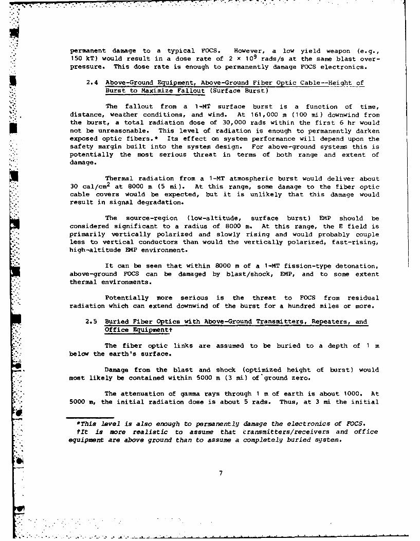
Interface Protection.--Interface protection devices operatepredominantly in one of two ways: by clamping (limiting the magnitude ofcurrents or voltages) or by filtering (removing energy in certain frequencybands).
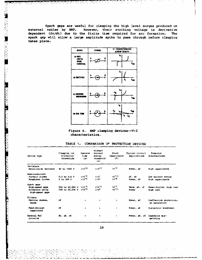
Practical clamping devices for E4P protection, which are generallyplaced in shunt with the input line, include varistors, diodes, and sparkgaps. A clamping device appears to be a high-resistance shunt until thedevice threshold is reached, at which time the device becomes a low-impedancepath and voltage is either clamped near the threshold point (varistor, diode)or drops to a lower value (spark gap). The V-I characteristics of the threetypes of clamping devices are shown in figure 4, and their characteristics arecompared in table 1.
-.' 15o is
. ." . .. . .. . . . .
, - .. - . - . . - , . . .
Spark gaps are useful for clamping the high level surges produced onexternal cables by EMP. However, their striking voltage is derivative
. dependent (dv/dt) due to the finite time required for arc formation. Thespark gap will allow a large amplitude spike to pass through before clampingtakes place.
•VICE "SYML V-1 CHARACTERSTICSDEVICE ~ MSOL LMEAR SCALES(
( " a) NOV IA
(METALOXICEVA ISTOR) Va
A 1
IA
-V 5" - Vii
! to(d! (41 TUK 0 -- 0 ..
Figure 4. EMP clamping devices--V-Icharacteristics.
TABLE 1. COMPARISON OP PROTECTIOS DEVICES
Hi qheetClamping (or Operate burnout Shunt Typical circuit Possible
Device type filterinq) time energy capacitance applications disadvantagesthresholds (s) threshold (F)
: (J)
VaristorsMetal-oxide varistor 40 to 1500 V <10
-9 <10
-3 10-
9 Power, af High capacitance
SemiconductorsForward diodes 0.2 to 0.6 V <10
-9 <101 10-L2 af, rf Low burnout energy
Breakdown diodes 2 to 200 v <10-9
<102
I()- Power, af High capacitance
Spark gapeH Nigh-speed gaps 550 to 20,000 V <10
-9 <10
- 3 10
"3 Termi a, ef Power-follow, high oost
Arrestors using 550 to 20,000 V <10-9
103
10-11 Power High cost
high-speed gaps
FiltersFerrite chokes, rf - - - Power, ef ineffective protection,beads dc saturation
Feed-throuqh rf Power, af Dielectric breakdowncapaci tore
General RIC dc, af, rf - - Power, af, rf Impedance mis-circuits matchinq
16
Diodes work well as protective elements for semiconductors in manyapplications, but must be protected themselves if large surges are present.
Varistors are most often used for protection of ac line interfaces.
It is particularly important that clamping devices be properlyinstalled so they will fullfill their protection capabilities. The protectiveelements should be mounted in a separate shielded enclosure as close to theinput-output port as practical. Lead lengths of a protective device and itsmounting should be minimized, to reduce the effects of clamp voltage increasedue to lead resistance,
AV C= I E R(Q/Zt.C SMP
K'; and clamp voltage overshoot due to lead inductance,
AV = L d I -"
C dt
A filter suppresses certain frequency components from an EMP surgeand can thus reduce energy allowed to pass to sensitive equipment inductors.
* Clamping devices operate only above a certain magnitude of surge voltage, butfilters respond to specific frequency components regardless of magnitude.They can thus suppress spurious frequencies that might cause system upset,
• "even if the interfering transient is not strong enough to activate a clamping* device. For example, filters are very useful in protecting low-voltaqe
digital circuits. Filters can also reduce the E4P wavefront slope, giving a*- slow spark gap time to respond.
Protective filters can be used only if the E4P surge energy does nothave the same frequency components as the desired signal. For example,
equipment terminating a dc power cable can be protected by a low-pass filter,which allows the desired low-frequency dc power through, but suppresses thehigh-frequency components of the E4P surge.
Devices that protect against transients must be rugged enough towithstand the transient and must be compatible with circuit operation.Consequently, each critical circuit must be analyzed separately before thebest means for protection can be designed. Some of the most importantconsiderations are the following: maximum operational voltage excursion,bandwidth or bit rate, circuit function, and the induced E4P waveform.
Each device described so far has a limited protective function and,by itself, may not protect equipment, Adequate protection sometimes requiresa hybrid circuit, which has more than one type of device to compensate fordeficiencies or to minimize possible side effects. A parallel spark gap andzener diode combination uses the zeners' subnanosecond response and lowbreakdown voltage to immediately clamp the transient surge to safe levels forthe equipment to be protected. Then, several nanoseconds later, the spark gapfires and protects the zener from burnout caused by excessive power dissi-pation. A series spark gap and varistor combination uses the essentiallyopen-circuit nature of the spark gap in its quiescent state for a high degree
17
of dc and ac isolation of the protective elements from the main circuit andthen uses the varistor to ensure that the spark gap will turn off in a dcsituation.
U In E4P coupling to cables, the common mode transient often dominatesthe differential mode. Cabling practices such as the use of twisted pairs andbalanced termination reduce the differential mode coupling. Interfacehardening can then be augmented by circuit designs that suppress vulnerabilityand sensitivity to common mode signals.I 3.5 Specific Guidance for EMP Protection of Fiber Optic Systems
There are many ways fiber optic systems can be protected:
(a) Install transmitter and receiver components in a high conduc-tivity metal enclosure whose walls are thick enough to adequately assure E4Pshielding and mechanical rigidity. The access cover should be as thick as theenclosure.
* (b) Eliminate all enclosure apertures except those that are*" absolutely necessary, such as those for the fiber optics, for the seams of the
access cover, and for the input/output (I/O) connectors.
(c) Place the power and data I/O lines in double braided shieldedcable or in metal conduit that terminates at both ends with peripheral shieldsto high conductivity metallic enclosures. Route I/O lines to eliminate EMIcoupling between power and signal lines.
(d) Provide transient suppression or filtering on all lines whereshielding is insufficient to prevent damage. Adequate shielding may be
*i impractical if power or data I/O lines are long and exposed to scattering-enhanced E4P fields.
(e) Use nonconductors, such as Kevlar or Aramid fibers, tostrengthen fiber optic cables. Do not include metal conductor power or signal
". lines in the fiber optic cable.
(f) Use a high conductivity I/O connector with a conductive metal, finish.
(g) Use a metal fiber optic connector or run the fiber through asmall-diameter metallic tube that is peripherally attached to the enclosureand is long enough to attenuate the local exterior E4P field.
3 (h) Provide good electrical contact between the enclosure and accesscover, with at least 0.50-in. (12.7 mm) mating surfaces or lips. The matingsurfaces should be tin plated, for a noncorrosive finish. The access cover
0: should be attached with screws spaced 2 in. (50.8 mm) apart and torqued to50 in.-lb. Nutplates and fast release fasteners must not be used.
1i
(i) Use an emi gasket in mating the access cover to the enclosure.The gasket should be metal mesh, metal spiral, or wire-filled rubber. If theabove guidelines are used to package the link components, the link can beprotected against upset and component damage. Use similar guidelines toharden the system elements that provide the I/O signal and the power to thefiber optic links.
(j) Use local battery uninterruptible power supplies wherepossible. Systems that are directly run from batteries are to some degreeisolated from power line transients, although the batteries are constantlyunder charge.
4. GUIDELINES FOR LOW-ALTITUDE NUCLEAR ENVIRONMENTS
For the low altitude or surface burst, effects other than EMP predominate,and the object is to (1) minimize damage to the system through system design,component selection, system installation and hardening measures and (2)provide for the reconstitution of a reasonable system through standardizationof various systems, subsystems, and interfaces and provision of interfacepoints.
FOCS are designed to account for losses inclrred in fibers, splices,optical coupling, and receiver sensitivity to achieve the maximum allowablerepeater spacing with a sufficient design margin for proper operation over thenormal environmental variations. Nuclear radiation effects are not consideredin deriving the loss budget. Additional losses that occur due to radiationeffects include increased fiber losses due to fiber darkening, reducedreceiver sensitivity and increased receiver noise, and reduced emitter
" output. In addition to reducing the repeater spacing and providing moredesign margin, the following guidelines can be applied to reduce the nuclearsusceptiblity of FOCS.
4.1 Initial Nuclear Radiation and Residual Radiation
The following guidelines should be implemented to protect FOCS duringinitial and residual radiation environments.
(a) Operate at long wavelengths (1.3 to 1.5 pm) and use Ge-dopedsilica core optical waveguides that do not contain phosphorus; operation at
* 1.5 urm is preferable over operation at 1.3 um.
(b) Use photodetectors with no internal gain; that is, avoid the useof avalanche photodiodes (APD's). If APD's are used, keep internal gain to a
• minimum. Provide sufficient current limiting to the photodetector to preventprompt-gamma-induced burnout. Photodetectors fabricated from II-V
*semiconductor material are preferred over those fabricated from Si or Ge.
(c) Insure that lasers do not overheat; for example, if air-conditioning in shelter stations fails, have an alternate cooling source.
19
* . . . .. . . . . . ... " . .
(d) Avoid the use of N-channel metal oxide semiconductor (NMOS)devices in electronic equipment; assess the radiation hardness of other MOSdevices before they are used in electronic equipment. Bipolar devices are
preferable when used with well-established principles of circuit design andconservative design margins.
(e) Provide for automatic power removal to prevent latchup and/orburnout in circuits using MOS, bipolar, and other semiconductor devices(unijunction transistors, silicon-controlled rectifiers, etc.); reset manuallyor automatically. In lieu of the above, hard circuit components with current
limiting designed into the circuits are required, but logic upset will stilloccur and reset is required (either automatic or manual).
(f) Bury fiber optic cable preferably at depths greater than 1 mC( 3 ft); bury repeaters if possible.
(g) Provide for operation at a reduced data rate; also determine how
information can be rerouted.
4.2 Electromagnetic Pulse
The following guidelines should be implemented to protect FOCS duringthe EMP environment.
(a) Avoid the use of metal members (e.g., strength members, core*. wraps, etc.) in fiber optic cable; use nonmetallic materials in fiber optic
cable whenever possible. If metal members are used, establish a groundingscheme for metal members of fiber optic cable, but take care to avoid EMP-
* induced current in ground loops.
(b) Put terminal protection devices (TPD's) on repeater power inputs
-. (from local power).
4.3 System-Generated Electromagnetic Pulse
The following guidelines should be implemented to protect FOCS duringthe system-generated (SGEMP) environment.
Use shielded cables (with rf shielding effectiveness of at least 30
:. dB) for power cables, signal interconnects, etc., to minimize the effects of*i SGE4P, and ground all cable penetrations to cabinets; also, ground all4. cabinets. Use TPD's for long cable runs.
4.4 Blast
The following guidelines should be implemented to protect FOCS during* the blast environment.
Avoid the use of thin-walled mobile buildings for shelters. Solidfixed-site structures (e.g., reinforced concrete, reinforced masonry block,
20
*. . . *-. . .~ . .' .+° .. + .. ... -
etc.) are recommended for exposed repeater stations and terminals. Keep- openings in buildings as small as possible. Locate entry and exit ports for"" cables, etc., on the side of the repeater station that is opposite the
expected or likely ground zero (e.g., industrial target) whenever possible;run cables radially away from probable ground zero. Allow rattle space(sufficient intervening space) between walls of repeater stations and
* equipment in the station. Provide for easy maintenance and rapid replacementfor fiber optic cables installed on utility poles.
4.5 Thermal Radiation
The following guidelines should be implemented to harden FOCS during
the thermal environment.
Avoid the use of plastics, thin metal components, and flammablematerials that may be exposed to intense thermal radiation. Locate cable,components, etc., in positions that are shielded from direct thermal exposurewhenever possible. Covering the cable (not burying) with a few inches ofearth significantly reduces thermal damage. If fiber optic cables are
*. exposed, they should be covered with a thick flame-resistant outer jacket(e.g., 2-mm thick flame-resistant rubber or PVC--polyvinyl chloride for buriedinstallations with above-ground terminations and 1-mm thick for above-groundinstallations carried on utility poles).
4.6 Implementing Guidelines
All the guidelines in section 4, except 4.1a and b, can be achieved by theuse of selected commercially available devices and materials, by followingaccepted nuclear weapon effects hardening procedures, or by institutingoperational modifications to the fiber optic system. Guideline 4.1a specifiesa fiber composition (Ge-doped silica core optical waveguide that does notcontain phosphorus) that research has shown to be a mitigation technique, butcommercial availability is not known. Likewise, the commercial availabilityof III-V photodetectors (refer to guideline 4.1b) that are suitable for someproposed FOCS opera":ions is not known.
5. SUMMARY
The guidelines suggested in this report should be given seriousconsideration when FOCS is being designed and installed. If the guidelinesare incorporated, they can protect a significant part of the national iOCSresources that might otherwise be rendered inoperable directly following andfor some considerable period of time after a nuclear attack.
21
I.
LITERATURE CITED
(1) Samuel Glasstone, The Effects of Nuclear Weapons, published jointly bythe Department of Defense and the Department of Energy, Washington, DC(1977).
(2) EdP Engineering and Design Principles, Bell Laboratories (1975).
(3) P. R. Tryhus, Ground Based Systems EMP Design Handbook, MRCH/2-M-211,
Mission Research Corporation (August 1977).
(4) EMP Engineering Practices Handbook, SRI, NAIO File No. 1460-2, (October1977),
V (5) R. A. Greenwall, EMP Hardening of Tactical Ground Systems ThroughElectro-Optical Techniques: Design Guidelines, Naval Ocean System CenterTechnical Report 645 (20 December 1980).
(6) J. R. Miletta et al, Defense Switched Network Design Practices forProtection Against High-Altitude Electromagnetic Pulse, Harry DiamondLaboratories HDL-SR-82-2 (July 1982).
22
" . . -

r7.%
DISTRIBUTION
ADMINISTRATOR DIRECTOR,DEFENSE TECHNICAL INFORMATION CENTER DEFENSE COMMUNICATIONS AGENCYATTN DTIC-DDA (12 COPIES) ATTN CODE 312CAMERON STATION ATTN CODE C313ALEXANDRIA, VA 22314 ATTN CODE 430 (PARKER)
WASHINGTON, DC 20305COMMANDERUS ARMY RSCH & STD GP (EUR) DEFENSE COMMUNICATIONS ENGINEER CENTERATTN CHIEF, PHYSICS & MATH BRANCH ATTN CODE R400FPO NEW YORK 09510 ATTN CODE R123, TECH LIB
1860 WIEHLE AVECOMMANDER RESTON, VA 22090
: US ARMY MISSILE & MUNITIONS
CETE R & SCHOOL DIRECTORATTN ATSK-CTD-F DEFENSE INTELLIGENCE AGENCYREDSTONE ARSENAL, AL 35809 ATTN DB 4C2, D. SPOHN
ATTN RTS-2A, TECH LIBDIRECTOR WASHINGTON, DC 20301US ARMY MATERIEL SYSTEMS ANALYSIS
ACTIVITY DIRECTORATTN DRXSY-MP DEFENSE NUCLEAR AGENCYABERDEEN PROVING GROUND, MD 21005 ATTN NATA
ATTN TITL (4 COPIES)DIRECTOR ATTN RAEVUS ARMY BALLISTIC RESEARCH LABS ATTN RAEE, G. BAKER (10 COPIES)ATTN DRDAR-TSB-S (STINFO) ATTN STNAATTN DRDAR-BLB, W. VAN ANTWERP WASHINGTON, DC 20305ATTN DRDAR-BLEABERDEEN PROVING GROUND, MD 21005 JOINT CHIEFS OF STAFF
ATTN J-3 RM 2D874US ARMY ELECTRONICS TECHNOLOGY WASHINGTON, DC 20301& DEVICES LABORATORY
ATTN DELET-DD NATIONAL COMMUNICATIONS SYSTEMFT MONMOUTH, NJ 07703 OFFICE OF THE MANAGER
DEPARTMENT OF DEFENSEHQ USAF/SAMI ATTN NCS-TS, DENNIS BODSON (100 COPIES)WASHINGTON, DC 20330 WASHINGTON, DC 20305
TELEDYNE BROWN ENGINEERING COMMANDERCUMMINGS RESEARCH PARK COMBINED ARMS CENTERATTN D. GUICE & FORT LEAVENWORTHATTN DR. MELVIN L. PRICE, MS-44 ATTN ATZL-CAD-LNHUNTSVILLE, AL 35807 FT LEAVENWORTH, KS 66027
ENGINEERING SOCIETIES LIBRARY DIRECTORATTN ACQUISITIONS DEPARTMENT NATIONAL SECURITY AGENCY345 E 47TH ST ATTN TDL
i:NE YORK, NY 10017 ATTN R-52, 0. VAN GUNTEN' ATTN S-232, D. VINCENT
IL BOEING MILITARY AIRPLANE FT GEORGE G. MEADE, MD 20755ATTN CLETUS SUTTER, M/S- K75-503801 SOUTH OLIVER COMMANDERWICHITA, KS 67210 BMD SYSTEMS COMMAND
DEPARTMENT OF THE ARMYASSISTANT TO THE SECRETARY OF DEFENSE ATTN BMDSC-AOLIBATOMIC ENERGY ATTN BMDSC-HLE, R. WEBBATTN MILITARY APPLICATIONS PO BOX 1500ATTN EXECUTIVE ASSISTANT HUNTSVILLE, AL 35807WASHINGTON, DC 20301
23
DISTRIBUTION (Cont'd)
DIVISION ENGINEER GENERAL ELECTRIC CO.US ARMY ENGR. DIV. HUNTSVILLE SPACE DIVISION
ATTN T. BOLT VALLEY FORGE SPACE CENTER
PO BOX 1600, WEST STATION ATTN J. ANDREWSHUNTSVILLE, AL 35807 Po BOX 8555
PHILADELPHIA, PA 19101
COMMANDERUS ARMY COMMUNICATIONS COMMAND GTE/SYLVANIAATTN CC-LOG-LEO ATTN J. KILLIANATTN CC-OPS-WS (CONNELL) 1 RESEARCH DRIVEATTN CC-OPS-PD WESTBORO, MA 01581ATTN CC-OPS-OSATTN ATSI-CD-MD HONEYWELL, INC
FT HUACHUCA, AZ 85613 AEROSPACE & DEFENSE GROUPATTN S. GRAFF
CHIEF ATTN W. STEWARTUS ARMY COMMUNICATIONS SYS AGENCY 13350 US HIGHWAY 19 SOUTH
DEPARTMENT OF THE ARMY CLEARWATER, FL 33516ATTN CCM-AD-SVATTN CCM-RD-T IIT RESEARCH INSTITUTE
FT MONMOUTH, NJ 07703 ELECTROMAG COMPATIBILITY ANALYSIS CENTERANT ACOAT
COMMANDER N SEVERNUS ARMY NUCLEAR & CHEMICAL AGENCY ANNAPOLIS, MD 21402ATTN MONA-WE
ATTN DR. BERBERET IIT RESEARCH INSTITUTE7500 BACKLICK ROAD ATTN I. MINDELBUILDING 2073 10 W 35TH STSPRINGFIELD, VA 22150 CHICAGO, IL 60616
COMMANDER IRT CORPUS ARMY TRAINING & DOCTRINE COMMAND ATTN J. KNIGHTONATTN ATCD-Z P0 BOX 81087FT MONROE, VA 23651 SAN DIEGO, CA 92138
BMD CORP JAYCORATTN CORPORATE LIBRARY SANTA BARBARA FACILITY7915 JONES BRANCH DRIVE ATTH W. RADASKYMCLEAN, VA 22101 P0 BOX 30281
360 SOUTH HOPE AVEBENDIX CORP SANTA BARBARA, CA 93105COMMUNICATION DIVISIONATTN DOCUMENT CONTROL KAMAN SCIENCESE JOPPA ROAD ATTN W. RICHBALTIMORE, MD 21204 ATTN A. BRIDGES
ATTN F. SHELTONDIKEWOOD CORPORATION ATTN N. BEAUCHAMP
ATTN TECHNICAL LIBRARY PO BOX 74631613 UNIVERSITY BLVD, NE COLORADO SPRINGS, CO 80933ALBUQUERQUE, NM 87102
LUTECH, INC.ELECTRO-MAGNETIC APPLICATIONS, INC. ATTN F. TESCHEATTN D. MEREWETHER PO BOX 1263PO BOX 8482 BERKELEY, CA 94701ALBUQUERQUE, NM 87198
MARTIN MARIETTA CORPATTN M GRIFFITH (2 COPIES)ATTN J CASALESEATTN B. BROULIKPO BOX 5837ORLANDO, FL 32855
24
DISTRIBUTION (Cont'd)
MCDONNELL DOUGLAS CORP ROCKWELL INTERNATIONAL
ATTN S. SCHNEIDER ATTN B-i DIV TIC (BAOB)
ATTN TECHNICAL LIBRARY SERVICES PO BOX 92098
5301 BOLSA AVE LOS ANGELES, CA 90009
HUNTINGTON BEACH, CA 92647
SCIENCE APPLICATIONS, INC.
MCDONNELL DOUGLAS CORP ATTN W. CHADSEY
ATTN D-6074, T. ENDER PO BOX 1303
PO BOX 516 MCLEAN, VA 22102
ST LOUIS, MO 63166SEA
MISSION RESEARCH CORPORAION MARINER SQUARE
ATTN J. RAYMOND SUITE 127ATTN J. CHERVENAK ATTN W. HUTCHINSON
5434 RUFFIN ROAD 1900 N. NORTHLAKE WAY
SAN DIEGO, CA 92123 PO BOX 31819
SEATTLE, WA 98103MISSION RESEARCH CORP
ATTN W. CREVIER SRI INTERNATIONAL
ATTN C. LONGMIRE ATTN E. VANCE
ATTN EMP GROUP ATTN A. WHITSON
PO DRAWER 719 333 RAVENSWOOD AVE
SANTA BARBARA, CA 93103 MENLO PARK, CA 94025
MISSION RESEARCH CORPORATION TRW ELECTRONICS & DEFENSE SYSTEMS GROUP
ATTN W. STARK ONE SPACE PARK
ATTN J. LUBELL ATTN W. GARGARO
ATTN W. WARE ATTN L. MAGNOLIA
PO BOX 7816 ATTN R. PLEBUCHCOLORADO SPRINGS, CO 80933 ATTN C. ADAMS
ATTN H. HOLLOWAYRICHARD L. MONROE ASSOCIATES ATTN E. HORGAN
1911 R STREET NW ATTN J. PENARSUITE 203 REDONDO BEACH, CA 90278
WASHINGTON, DC 20009
US ARMY ELECTRONICS RESEARCH
NORTHROP CORP & DEVELOPMENT COMMANDELECTRONIC DIVISION ATTN COMMANDER, DRDEL-CG
ATTN LEW SMITH ATTN TECHNICAL DIRECTOR, DRDEL-CT
ATTN RAD EFFECTS GRP ATTN PUBLIC AFFAIRS OFFICE, DRDEL-IN
ATTN B. AHLPORT
2301 W. 120TH ST HARRY DIAMOND LABORATORIESHAWTHORNE, CA 90250 ATTN CO/TD/TSO/DIVISION DIRECTORS
ATTN RECORD COPY, 81200R&D ASSOCIATES ATTN HDL LIBRARY, 81100 (3 COPIES)
ATTN DOCUMENT CONTROL ATTN HDL LIBRARY, 81100 (WOODBRIDGE)
ATTN W. GRAHAM ATTN TECHNICAL REPORTS BRANCH, 81 300ATTN C MO ATTN LEGAL OFFICE, 97000
ATTN M. GROVER ATTN CHAIRMAN, EDITORIAL COMMITTEE
PO BOx 9695 ATTN CHIEF, 20240MARINA DEL REY, CA 90291 ATTN CHIEF, 21000 (10 COPIES)
ATTN CHIEF, 21100RAYTHEON CO ATTN CHIEF, 21200
ATTN G. JOSHI ATTN CHIEF, 21300
ATTN H. FLESCHER ATTN CHIEF, 21400
HARTWELL ROAD ATTN CHIEF, 21500
BEDFORD, MA 01730 ATTN CHIEF, 22000
ATTN CHIEF, 22100
ATTN CHIEF, 22300 (2 COPIES)
ATTN CHIEF, 22800
ATTN CHIEF, 22900ATTN REYZER, R., 21300
ATTN SHARE, S., 22100
ATTN SWETON, J., 21300
25
-'. A
* t.


![VESA Holes 4 - M8 116 - LG Electronics · 2020. 1. 30. · [75xs2e dimension] - applied model: 75xs2e - unit: mm 116 11.8 11.8 11.8 11.8 1675.2 953.6 600 400 vesa holes 4 - m8 600](https://img.pdfslide.us/doc/110x75/60afd7d1a1ba645bf236e933/vesa-holes-4-m8-116-lg-electronics-2020-1-30-75xs2e-dimension-applied.jpg)