Embed Size (px)
Citation preview
Liberty Bell Components, Inc. 11631 Seaboard Circle, Stanton, CA 90680 (888)820-8885Fax: (888)820-8884 email: [email protected] website: www.libertycomponents.com
INTROLiberty Components is a master distributor of Passive Components located in Southern California serving the continental United States. We pride ourselves with the best of quality and service. Our reseller and distributor network though out the United States sells to end-users in the Medical, Telecommunication, and various Manufacturing industries. All our components are manufactured under strict ISO 9002:94 certified facilities in Japan, Taiwan, and Korea. We invite you to look though this catalog and call us for samples or quotes of your passive component needs.
Liberty Components is a stocking master distributor with over 200 million components ready to ship at a moments notice. Our inventory includes resistors, capacitors and diodes of all values, tolerances and sizes in both traditional through hole and SMD (Surface Mount Device) packaging.
Liberty Components also specializes in custom OEM passive components. We are able to customize passive components to your specification under your private brand label. Please call us for your custom OEM compo-nents.
Please feel free to give us a call. Whether it's 1000pcs, 10 million pcs or customized components, Liberty is your source to all your passive component needs.

II

III Liberty Bell Components, Inc. 11631 Seaboard Circle, Stanton, CA 90680 (888)820-8885
Fax: (888)820-8884 email: [email protected] website: www.libertycomponents.com
HISTORYLiberty Components was established by Gary Lee in 1978. At inception, Liberty was know as “Liberty Interna-tional Components, Inc.” and was a sales office for Firstohm, Ltd., one of the largest resistor manufacturers in Taiwan at its time. Through the years, Liberty expanded its product line with partnership factories located in Taiwan, Korea and Japan to provide more than through-hole resistors to our customers. We offer quality passive electronic components at competitive prices.
In 2002, with the passing of our founder, the corporate name for Liberty changed to Liberty Bell Components, Inc. We are still the same company with many of the same employees. We at Liberty have continued the legacy of our founder to provide the best quality components with the best service in the industry at the most competitive pricing on the market.
QUALITYThe quality of Liberty components is second to none. While many of our competitors in the through-hole resistor business have moved on to “Copper Clad” leads and use thinner leads to reduce cost, Liberty refuses to use sub-standard raw materials and practices to build our components. Our through-hole resistors are still built on industry standard lead thicknesses for its wattage rating and we only use tinned 100% copper leads.
Liberty Bell Components, Inc. 11631 Seaboard Circle, Stanton, CA 90680 (888)820-8885Fax: (888)820-8884 email: [email protected] website: www.libertycomponents.com
Table of Contents
1. Fixed Component a. Capacitors
i. Aluminum Electrolytic Capacitor 1. EGA - Standard Axial 85°C 2 2. EGR - Standard Radial 85°C 4 3. EWA - Standard Axial 105°C 7 4. EWR - Standard Radial 105°C 9 5. ENA - Non-Polar Axial 85°C 12 6. ENR - Non-Polar Radial 85°C 13 7. ESM - 7mm Height Standard Radial 85°C 15 8. ESH - 7mm Height Standard Radial 105°C 17 9. ESS – 5mm Height Standard Radial 85°C 18 10. ELL - Low Leakage Standard Radial 85°C 19 11. ESL - Low Leakage 7mm Height 85°C 21 12. GLZ - Low Impedance Radial 105°C 22
ii. Battery Capacitor 1. DB – Electric Double Layer Capacitor 24
iii. Ceramic Disc Capacitor 1. CDC - Standard Ceramic Disc 25 2. CKD - High Voltage Ceramic Disc 28
iv. Multilayer Ceramic Capacitor 1. CMA - Standard Monolithic Axial 34 2. CMR - Standard Monolithic Radial 38
v. Poly Switch (PPTC Resettable Fuse) Capacitor 1. PS06 - Operation Current: 6v 0.75A-2.5A 42 2. PS16 - Operation Current: 16v 3A-14A 44 3. PS30 - Operation Current: 30v 0.9A-9A 46 4. PS60 - Operation Current: 60v 0.05A-3.75A 48 5. PS90 - Operation Current: 90v 0.2A-0.9A 50 6. PS250/600 - Operation Current: 250v / 600v 51
vi. Polyester Film Capacitor1. PEI - Standard Polyester 54 2. MER - Metalized Polyester 56 3. MPR - Metalized Polypropylene 58
b. Resistors i. RCF - Carbon Film Fixed Resistor 60 ii. RFP - Carbon Film Flame Proof Resistor 63 iii. RMF - Metal Film Resistor 64 iv. RFM - Metal Film Flame Proof Resistor 68 v. RMO - Metal Oxide Resistor 70 vi. RFU - Flame Proof Fusible Resistor 72 vii. RLA - Wirewound Rectangular Resistor 75 viii. RLE - Wirewound Flame Proof Resistor 78

Liberty Bell Components, Inc. 11631 Seaboard Circle, Stanton, CA 90680 (888)820-8885Fax: (888)820-8884 email: [email protected] website: www.libertycomponents.com
Table of Contents
i. REH - Wirewound High Power Resistor 79 ii. RER - Wirewound High Power Ribbon Resistor 80 iii. FSQ – Fusible Wirewound Resistor 81 iv. RNL - Resistor Networks 82
b. Diodes i. Glass/Silicon General Rectifiers
1. PR – Glass/Silicon Passivated Rectifiers 84 a. 1.0 amp / DO-41 / 1N4001G Thru 1N4007G 86 b. 1.5 amp, 2.0 amp / DO-15 / 1N5391 Thru 1N5399G87 88 c. 3.0 amp / DO-27 / 1N5400G Thru 1N5408G 90 d. 6.0 amp / DO-15 / P600AG Thru P600MG 94 e. 2.5 amp / DO-15 / TL251G Thru RL257G 96
2. Surface Mount Device a. Capacitors
i. Multilayer Ceramic Chip Capacitors 1. CMC - Standard Multilayer Ceramic Chip Capacitors 98 2. CFK - Safety Certified Chip Capacitor Class: X1Y2 112 3. CFH - Safety Certified Chip Capacitor Class: X2Y3 116 4. CFV - High Voltage Chip Capacitor (4000 vDC to 6000 vDC) 120 5. CMH - High Q and Low ESR Chip Capacitors 124
ii. Poly Switch (PPTC Resettable Fuse Capacitor) 1. PS-SM - Operation Current: 6v to 60v 0.3A-3A 129 2. PSWSM - Operation Current: 6v to 60v 0.14A-1.9A 131 3. PSxxx - Specialized SMD Fuse Capacitor 133
b. Resistors i. Thick Film Chip Resistors
1. MCR - Thick Film Chip Resistor (General Purpose) 135 2. HPR - High Power Thick Film Chip Resistor 140 3. TCR - Trimmable Chip Resistor 144 4. SCR - Surge Chip Resistor 146 5. HVR - High Voltage Chip Resistor 148 6. HRR - High Resistance Chip Resistor 150 7. MSR - Metal Strip Current Sensing Chip Resistor 152
ii. Thick Film Chip Array 1. RCA - Chip Resistor Network 155
c. Diodes i. General Rectifiers 162
1. 1.0 amp / SMA 164 2. 2.0 amp / SMB 1663. 3.0 amp / SMC 168 4. 3.0 amp / SMD 170

.

Fixe
d C
ompo
nent
Fixe
d C
ompo
nent
Cap
acito
rsC
apac
itors
Fixe
d C
ompo
nent
Fixe
d C
ompo
nent
Res
isto
rsR
esis
tors
Fixe
d C
ompo
nent
Fixe
d C
ompo
nent
Dio
des
Dio
des
Sur
face
Mou
nt
Sur
face
Mou
nt
Cap
acito
rsC
apac
itors
Sur
face
Mou
nt
Sur
face
Mou
nt
Res
isto
rsR
esis
tors
Sur
face
Mou
nt
Sur
face
Mou
nt
Dio
des
Dio
des
2
Fixed Com
ponentFixed C
omponent
Capacitors
Capacitors
Fixe
d C
ompo
nent
Cap
acito
rs
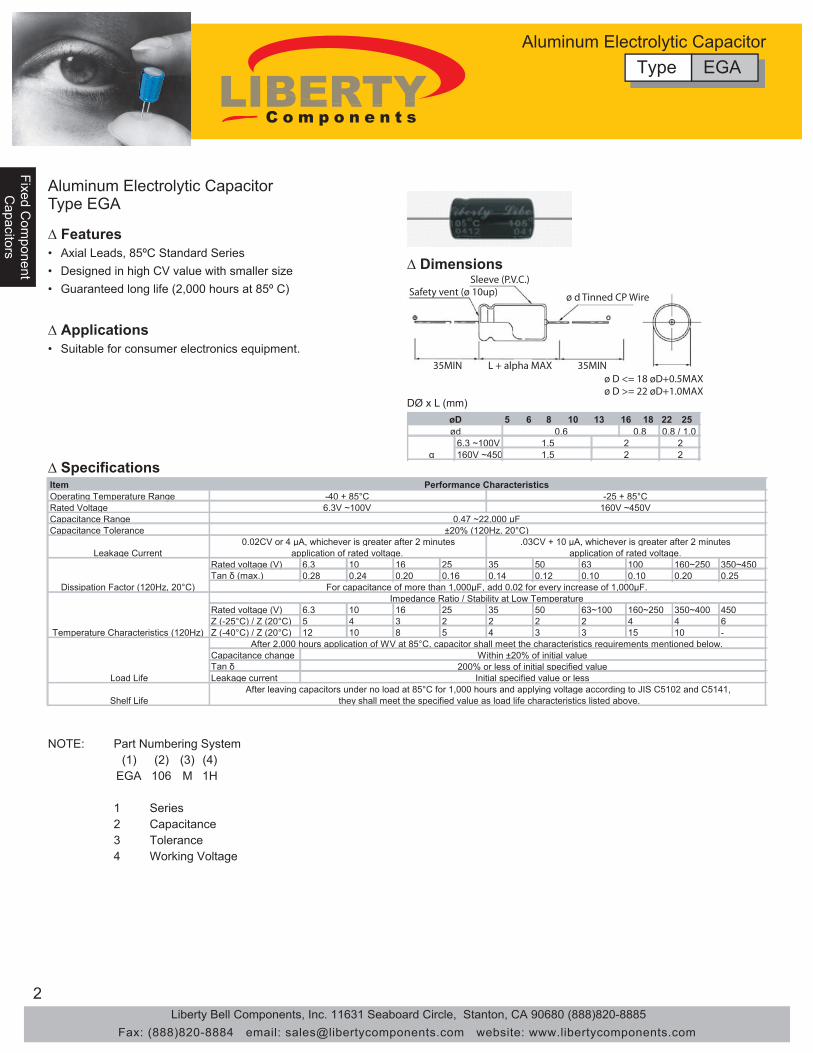
35MIN L + alpha MAX 35MIN
Safety vent (ø 10up)Sleeve (P.V.C.)
ø d Tinned CP Wire
ø D <= 18 øD+0.5MAXø D >= 22 øD+1.0MAX
5 6 8 10 13 16 18 22 25
6.3 ~100V 160V ~450
0.8 0.8 / 1.0 22
22α
øDød 0.6
1.51.5
Item Operating Temperature RangeRated VoltageCapacitance RangeCapacitance Tolerance
Rated voltage (V) 6.3 10 16 25 35 50 63 100 160~250 350~450 Tan δ (max.) 0.28 0.24 0.20 0.16 0.14 0.12 0.10 0.10 0.20 0.25
Rated voltage (V) 6.3 10 16 25 35 50 63~100 160~250 350~400 450Z (-25°C) / Z (20°C) 5 4 3 2 2 2 2 4 4 6Z (-40°C) / Z (20°C) 12 10 8 5 4 3 3 15 10 -
Capacitance change Tan δLeakage current
Impedance Ratio / Stability at Low Temperature
After 2,000 hours application of WV at 85°C, capacitor shall meet the characteristics requirements mentioned below.
200% or less of initial specified value Initial specified value or less
Within ±20% of initial value
-40 + 85°C 6.3V ~100V
Performance Characteristics -25 + 85°C
160V ~450V
0.02CV or 4 μA, whichever is greater after 2 minutes
0.47 ~22,000 μF ±20% (120Hz, 20°C)
.03CV + 10 μA, whichever is greater after 2 minutes
Shelf Life
Load LifeAfter leaving capacitors under no load at 85°C for 1,000 hours and applying voltage according to JIS C5102 and C5141,
they shall meet the specified value as load life characteristics listed above.
Temperature Characteristics (120Hz)
Dissipation Factor (120Hz, 20°C)
Leakage Current application of rated voltage. application of rated voltage.
For capacitance of more than 1,000μF, add 0.02 for every increase of 1,000μF.
NOTE: (1) (2) (3) (4)
EGA 106 M 1H
1234
ToleranceWorking Voltage
Part Numbering System
SeriesCapacitance
Aluminum Electrolytic CapacitorType EGA
∆ Features• Axial Leads, 85ºC Standard Series• Designed in high CV value with smaller size• Guaranteed long life (2,000 hours at 85º C)
∆ Applications
∆ Specifications
∆ Dimensions
• Suitable for consumer electronics equipment.
DØ x L (mm)
Type EGAAluminum Electrolytic Capacitor
Liberty Bell Components, Inc. 11631 Seaboard Circle, Stanton, CA 90680 (888)820-8885Fax: (888)820-8884 email: [email protected] website: www.libertycomponents.com

3
Fixed Com
ponentC
apacitors
Fixe
d C
ompo
nent
Fixe
d C
ompo
nent
Cap
acito
rsC
apac
itors
∆ Dimensions
Type EGAAluminum Electrolytic Capacitor
•
Ripple current (mA) at 85°C 120 Hz
Dφ x L (mm) WV(SV)
Cap (μF) 6.3(8)
10(13)
16(20)
25(32)
35(44)
50(63)
63(75)
100(125)
0.47 5 x 13 5 5 x 13 101 5 x 13 10 5 x 13 18
2.2 5 x 13 23 5 x 13 273.3 5 x 13 30 5 x 13 344.7 5 x 13 36 5 x 13 40
5631 x 3.65531 x 50531 x 51431 x 57331 x 50102161 x 80931 x 3.65831 x 3.60731 x 58531 x 50531 x 52254161 x 852161 x 3.650131 x 3.65931 x 3.60831 x 50631 x 53309102 x 856161 x 804161 x 3.651131 x 3.650131 x 3.60931 x 50731 x 574
100 5 x 13 110 6.3 x 13 130 6.3 x 13 145 6.3 x 16 170 8 x 16 200 8 x 16 220 8 x 20 260 10 x 21 310220 6.3 x 13 180 6.3 x 16 220 8 x 16 260 8 x 16 280 8 x 20 340 8 x 20 370 10 x 21 440 13 x 26 560330 6.3 x 16 250 8 x 16 300 8 x 16 320 8 x 16 350 8 x 20 410 10 x 21 510 13 x 26 650 13 x 31 730470 8 x 16 330 8 x 16 350 8 x 16 390 8 x 20 460 10 x 21 550 13 x 26 740 13 x 26 780 16 x 31 960
1000 8 x 20 530 8 x 20 570 10 x 21 700 10 x 26 830 13 x 26 980 13 x 31 1130 16 x 31 1330 18 x 41 16402200 10 x 21 850 13 x 26 1100 13 x 26 1190 13 x 31 1330 16 x 31 1580 16 x 41 1930 18 x 41 2080 25 x 51 25603300 13 x 26 1210 13 x 26 1290 13 x 31 1460 16 x 31 1700 16 x 41 1810 18 x 41 2260 22 x 51 23704700 13 x 26 1400 13 x 31 1550 16 x 31 1840 16 x 41 2190 18 x 41 2380 22 x 51 2510 25 x 41 39706800 13 x 31 1650 16 x 31 1930 16 x 41 2310 18 x 41 2480 22 x 51 2760
10000 16 x 31 1990 16 x 41 2350 18 x 41 2520 22 x 51 3240 25 x 51 350015000 16 x 41 2480 18 x 41 2630 22 x 51 331022000 18 x 41 2730 22 x 51 3390 25 x 51 3500
WV(SV) Cap (μF)
160(200)
200(250)
250(300)
350(400)
400(450)
450(500)
9161 x 80261 x 3.60261 x 3.66131 x 3.618261 x 83361 x 83361 x 80361 x 3.64231 x 3.62.2
3.3 6.3 x 16 37 6.3 x 16 37 8 x 16 40 8 x 16 40 8 x 20 45 8 x 20 384.7 8 x 16 50 8 x 16 50 8 x 16 50 8 x 20 55 10 x 21 60 10 x 21 5010 8 x 20 80 8 x 20 80 10 x 21 90 10 x 26 100 13 x 26 110 13 x 26 9022 10 x 21 130 10 x 26 145 13 x 26 160 13 x 26 160 13 x 31 170 16 x 31 16033 10 x 26 180 13 x 26 195 13 x 26 195 13 x 31 200 16 x 31 230 16 x 31 19047 13 x 26 230 13 x 31 230 13 x 31 240 16 x 31 270 16 x 41 310 16 x 41 270
100 16 x 31 400 16 x 31 400 16 x 41 450 18 x 41 460 22 x 51 370Case size Ripple
220 16 x 41 670 18 x 41 690 22 x 41 764
WV Cap(μF) \ Frequency 50 Hz 120 Hz 300 Hz 1 KHz 10 KHz~
6.3~100
~ 47 0.75 1 1.35 1.57 2.00100 ~ 470 0.80 1 1.23 1.34 1.50
1,000 ~ 22,000 0.85 1 1.10 1.13 1.15160~450 1 ~ 220 0.80 1 1.25 1.40 1.60
Liberty Bell Components, Inc. 11631 Seaboard Circle, Stanton, CA 90680 (888)820-8885Fax: (888)820-8884 email: [email protected] website: www.libertycomponents.com

4
Fixed Com
ponentFixed C
omponent
Capacitors
Capacitors
Fixe
d C
ompo
nent
Cap
acito
rs
Aluminum Electrolytic CapacitorType EGR
∆ Specifications
5 6.3 8 10 13 16 18 20 22 252 2.5 3.5 5 5 7.5 7.5 10 10 12.5
~100WV 160WV~
0.61.52
0.51.01.5
122
0.81.52
øDP ød
α
Item Operating
Temperature RangeRated Voltage
Capacitance RangeCapacitance Tolerance
Rated voltage (V) 6.3 10 16 25 35 50 63 100 160~250 350~450 Tan δ (max.) 0.24 0.2 0.17 0.15 0.12 0.1 0.1 0.1 0.2 0.25
Rated voltage (V) 6.3 10 16 25 35 50 63 100 160~200 250~350 400 450Z (-25°C) / Z (20°C) 5 4 3 2 2 2 2 2 3 4 6 15Z (-40°C) / Z (20°C) 12 10 8 5 4 3 3 3 4 8 10 -
Capacitance change Tan δLeakage current
Shelf Life
Performance Characteristics
-25 + 85°C -40 + 85°C 160V ~450V 6.3V ~100V
0.1 ~22,000 μF
±20% (120Hz, 20°C) .03CV + 10 μA, whichever is greater after 2 minutes 0.02CV or 4 μA, whichever is greater after 2 minutes
Load Life
After 2,000 hours application of WV at 85°C, capacitor shall meet the characteristics requirements mentioned below. Within ±20% of initial value
200% or less of initial specified value Initial specified value or less
Temperature Characteristics
(120Hz)
Dissipation Factor (120Hz, 20°C)
Leakage Current
After leaving capacitors under no load at 85°C for 1,000 hours and applying voltage according to JIS C5102 and C5141, they shall meet the specified value as load life characteristics listed above.
application of rated voltage. application of rated voltage.
For capacitance of more than 1,000μF, add 0.02 for every increase of 1,000μF. Impedance Ratio / Stability at Low Temperature
NOTE: (1) (2) (3) (4)
EGR 106 M 1H
1234
ToleranceWorking Voltage
Part Numbering System
SeriesCapacitance
∆ Features• Radial Leads, 85ºC Standard Series• Guaranteed long life (2,000 hours at 85º C)
∆ Applications• Suitable for consumer electronics equipment.
∆ Dimensions
Type EGRAluminum Electrolytic Capacitor
DØ x L (mm)
Liberty Bell Components, Inc. 11631 Seaboard Circle, Stanton, CA 90680 (888)820-8885Fax: (888)820-8884 email: [email protected] website: www.libertycomponents.com

5
Fixed Com
ponentC
apacitors
Fixe
d C
ompo
nent
Fixe
d C
ompo
nent
Cap
acito
rsC
apac
itors
∆ Dimensions
Type EGRAluminum Electrolytic Capacitor
Dφ x L (mm)
Ripple current (mA) at 85°C 120 Hz
WV(SV)Cap (μF)
6.3(8)
10(13)
16(20)
25(32)
35(44)
50(63)
63(75)
0.1 5 x 11 1.30.22 5 x 11 2.90.33 5 x 11 4.30.47 5 x 11 6.2
1 5 x 11 172.2 5 x 11 283.3 5 x 11 354.7 5 x 11 40
5611 x 50611 x 50611 x 55511 x 50511 x 50122 5 x 11 65 5 x 11 65 5 x 11 75 5 x 11 80 5 x 11 90 5 x 11 95 5 x 11 10033 5 x 11 80 5 x 11 85 5 x 11 90 5 x 11 95 5 x 11 105 5 x 11 125 6.3 x 11 140
475 x 11 95 5 x 11 100 5 x 11 110 5 x 11 115 6.3 x 11 145 8 x 11 175 8 x 11 185
5 x 11 130 6.3 x 11 155 6.3 x 11 170
1005 x 11 135 5 x 11 145 6.3 x 11 170 6.3 x 11 190 6.3 x 11 210 8 x 11 260 10 x 12 300
08211 x 808111 x 506111 x 5
2205 x 11 200 6.3 x 11 240 6.3 x 11 260 8 x 11 330 10 x 12 385 10 x 12 430 10 x 16 490
5 x 11 220 6.3 x 11 280 8 x 11 350 10 x 16 450
3306.3 x 11 270 6.3 x 11 290 8 x 11 370 10 x 12 440 10 x 12 490 10 x 16 590 10 x 20 7105 x 11 230 6.3 x 11 320 8 x 11 390 10 x 20 620
4706.3 x 11 320 6.3 x 11 350 8 x 11 440 10 x 12 550 10 x 16 650 13 x 20 760 13 x 20 900
8 x 11 400 10 x 16 580 10 x 20 760
10008 x 11 540 10 x 12 650 10 x 16 790 10 x 20 960 13 x 20 1150 13 x 25 1350 16 x 32 1400
8 x 14 660 10 x 12 700 10 x 16 860 10 x 25 1100 16 x 25 1450 16 x 25 1300
220010 x 20 1000 10 x 20 1100 13 x 20 1300 13 x 25 1550 16 x 25 1800 16 x 36 2100 18 x 36 230010 x 16 890 10 x 16 990 10 x 20 1000 16 x 25 1700 16 x 32 1910 16 x 32 1980 22 x 36 2550
330010 x 20 1190 13 x 20 1450 13 x 25 1700 16 x 25 1980 16 x 36 2280 18 x 36 2500 20 x 40 2700
13 x 20 1550 13 x 25 1800 16 x 32 2100 22 x 30 2450 25 x 30 2600
470013 x 20 1550 13 x 25 1800 16 x 25 2100 16 x 32 2450 18 x 36 2700 20 x 40 2900 22 x 50 3400
13 x 25 1850 16 x 25 2200 16 x 36 2500 25 x 30 2900 25 x 40 3200
680013 x 25 1920 16 x 25 2250 16 x 36 2650 18 x 36 2900 20 x 40 3000 22 x 50 3500 25 x 50 3900
16 x 25 2250 16 x 36 2600 18 x 40 2800 25 x 40 3300
1000016 x 25 2350 16 x 36 2700 18 x 36 2950 20 x 40 3000 22 x 50 3700 25 x 50 4000
16 x 32 2550 16 x 36 2710 18 x 40 2800 25 x 40 3600
1500016 x 36 2850 18 x 36 3100 20 x 40 3400 22 x 50 3800 25 x 50 430016 x 32 2550 16 x 36 2880 18 x 40 3100 25 x 40 3600
2200018 x 36 3200 18 x 40 3400 22 x 50 4200 25 x 50 450022 x 30 3200 25 x 30 3300 25 x 40 4000
3300022 x 50 3900 22 x 50 4500 25 x 50 480025 x 40 3800 25 x 40 4800
4700022 x 50 3900 25 x 50 5000
Case Size ripple
Liberty Bell Components, Inc. 11631 Seaboard Circle, Stanton, CA 90680 (888)820-8885Fax: (888)820-8884 email: [email protected] website: www.libertycomponents.com

6
Fixed Com
ponentFixed C
omponent
Capacitors
Capacitors
Fixe
d C
ompo
nent
Cap
acito
rs
∆ Dimensions
Type EGRAluminum Electrolytic Capacitor
Dφ x L (mm)
Ripple current (mA) at 85°C 120 Hz
WV(SV)Cap (μF)
100(125)
160(200)
200(250)
250(300)
350(400)
400(450)
450(500)
0.1 5 x 11 2.1 6.3 x 11 2.10.22 5 x 11 4.7 6.3 x 11 4.7
711 x 3.6711 x 533.02111 x 3.65111 x 3.65111 x 3.65111 x 3.60111 x 574.0
15 x 11 21 6.3 x 11 22 6.3 x 11 22 6.3 x 11 22 6.3 x 11 22 8 x 11 25 8 x 11 23
6.3 x 11 20
2.25 x 11 30 6.3 x 11 33 6.3 x 11 33 6.3 x 11 33 8 x 11 38 10 x 12 45 10 x 12 35
6.3 x 11 30 8 x 11 38 8 x 11 28
3.35 x 11 40 6.3 x 11 40 6.3 x 11 40 8 x 11 46 10 x 12 55 10 x 12 55 10 x 16 45
6.3 x 11 40 8 x 11 43 8 x 11 48 10 x 12 40
4.75 x 11 45 6.3 x 11 50 8 x 11 55 8 x 11 55 10 x 12 65 10 x 16 70 10 x 20 55
6.3 x 11 50 6.3 x 11 50 8 x 11 55 10 x 12 60 10 x 12 46
106.3 x 11 75 8 x 11 80 10 x 12 95 10 x 16 105 10 x 20 115 13 x 20 130 13 x 20 90
0802 x 010961 x 010921 x 0100121 x 010811 x 80711 x 5
226.3 x 11 130 10 x 16 155 10 x 20 170 13 x 20 190 13 x 25 200 16 x 25 240 16 x 25 165
10 x 12 130 10 x 16 150 10 x 20 150 13 x 20 150 13 x 25 200 13 x 25 140
338 x 11 180 10 x 20 205 13 x 20 230 13 x 20 230 16 x 25 275 16 x 32 300 16 x 36 230
10 x 16 180 10 x 20 200 10 x 20 200 13 x25 240 16 x 25 240 16 x 25 180
4710 x 12 230 13 x 20 270 13 x 20 270 13 x 25 300 16 x 36 380 16 x 36 370 18 x 40 3008 x 11 200 10 x 20 210 13 x 20 270 16 x 25 300 16 x 25 280 16 x 32 220
68 10 x 12 270 13 x 20 350 13 x 25 350 16 x 25 380 16 x 25 400 16 x 32 340 18 x 36 260
10010 x 20 370 13 x 25 430 16 x 32 530 16 x 32 520 18 x 40 590 20 x 40 550 22 x 40 35010 x 16 340 16 x 25 450 16 x 25 440 18 x 36 520 18 x 36 440 18 x 40 280
22013 x 25 620 16 x 36 800 18 x 36 810 20 x 40 740 22 x 50 850 25 x 50 75013 x 20 550 16 x 32 580 16 x 36 700 18 x 36 680 22 x 50 760 22 x 50 650 25 x 50 350
33013 x 25 760 18 x 40 940 20 x 40 1130 22 x 50 1170
18 x 36 800 18 x 40 950 20 x 40 1000 25 x 50 1000
47016 x 25 1000 22 x 40 1410 22 x 50 1490 25 x 50 1600
18 x 40 1200 22 x 40 1300 22 x 50 1400
100018 x 40 1380 25 x 50 190018 x 36 1350
220022 x 50 240022 x 50 2400
330025 x 50 2900
Case Size Ripple
• • Allowable ripple vs. Ambient temperature
WV Cap(μF) Frequency 50 Hz 120 Hz 300 Hz 1 KHz 10 KHz~
6.3~100 ~ 68 0.75 1 1.35 1.57 2.00
100 ~ 470 0.80 1 1.23 1.34 1.501,000 ~ 47,000 0.85 1 1.10 1.13 1.15
160~4500.47 ~ 220 0.80 1 1.25 1.40 1.60
330 ~ 1,000 0.95 1 1.10 1.13 1.15
Ambient Temp. (°C) ~ +70 +85
Liberty Bell Components, Inc. 11631 Seaboard Circle, Stanton, CA 90680 (888)820-8885Fax: (888)820-8884 email: [email protected] website: www.libertycomponents.com

7
Fixed Com
ponentC
apacitors
Fixe
d C
ompo
nent
Fixe
d C
ompo
nent
Cap
acito
rsC
apac
itors
35MIN L + alpha MAX 35MIN
Safety vent (ø 10up)Sleeve (P.V.C.)
ø d Tinned CP Wire
ø D <= 18 øD+0.5MAXø D >= 22 øD+1.0MAX
5 6 8 10 13 16 18 22 25
6.3 ~100V 160V ~450
0.8 0.8 / 1.0 22
22α
øDød 0.6
1.51.5
Item Operating Temperature RangeRated VoltageCapacitance RangeCapacitance Tolerance
Rated voltage (V) 6.3 10 16 25 35 50 63 100 160~250 350~450 Tan δ (max.) 0.28 0.24 0.20 0.16 0.14 0.12 0.10 0.10 0.20 0.25
Rated voltage (V) 6.3 10 16 25 35 50 63~100 160~250 350~400 450Z (-25°C) / Z (20°C) 5 4 3 2 2 2 2 4 4 6Z (-40°C) / Z (20°C) 12 10 8 6 5 4 4 15 10 -
Capacitance change Tan δLeakage current
Impedance Ratio / Stability at Low Temperature
After 2,000 hours application of WV at 105°C, capacitor shall meet the characteristics requirements mentioned below.
200% or less of initial specified value Initial specified value or less
Within ±20% of initial value
-40 + 105°C 6.3V ~100V
Performance Characteristics -25 + 105°C
160V ~450V
0.02CV or 4 μA, whichever is greater after 2 minutes
0.47 ~22,000 μF ±20% (120Hz, 20°C)
.03CV + 10 μA, whichever is greater after 2 minutes
Shelf Life
Load LifeAfter leaving capacitors under no load at 105°C for 1,000 hours and applying voltage according to JIS C5102 and C5141,
they shall meet the specified value as load life characteristics listed above.
Temperature Characteristics (120Hz)
Dissipation Factor (120Hz, 20°C)
Leakage Current application of rated voltage. application of rated voltage.
For capacitance of more than 1,000μF, add 0.02 for every increase of 1,000μF.
NOTE: (1) (2) (3) (4)
EWA 106 M 1H
1234
ToleranceWorking Voltage
Part Numbering System
SeriesCapacitance
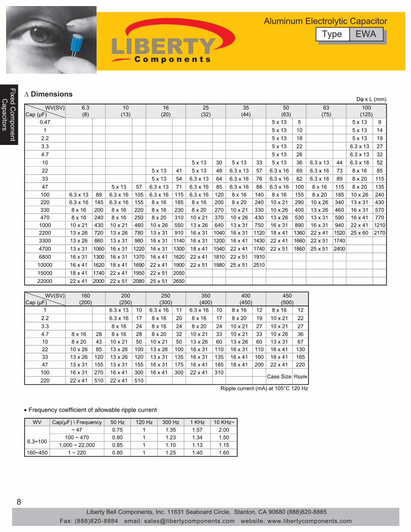
Aluminum Electrolytic CapacitorType EWA
∆ Features• Axial Leads, 105ºC Standard Series• Designed in high CV value with smaller size• Guaranteed long life (2,000 hours at 105º C)
∆ Applications
∆ Specifications
∆ Dimensions
• Suitable for high reliabilty equipment in the medical, telcom and industrial applications.
Type EWAAluminum Electrolytic Capacitor
DØ x L (mm)
Liberty Bell Components, Inc. 11631 Seaboard Circle, Stanton, CA 90680 (888)820-8885Fax: (888)820-8884 email: [email protected] website: www.libertycomponents.com
8
Fixed Com
ponentFixed C
omponent
Capacitors
Capacitors
Fixe
d C
ompo
nent
Cap
acito
rs
∆ Dimensions
Type EWAAluminum Electrolytic Capacitor
•
Ripple current (mA) at 105°C 120 Hz
Dφ x L (mm)
WV(SV) Cap (μF)
160(200)
200(250)
250(300)
350(400)
400(450)
450(500)
2161 x 82161 x 80161 x 3.61161 x 3.60131 x 3.612212 x 019102 x 87161 x 80261 x 87161 x 3.62.27212 x 017212 x 014202 x 84261 x 84261 x 83.3
4.7 8 x 16 28 8 x 16 28 8 x 20 32 10 x 21 33 10 x 21 33 10 x 26 3610 8 x 20 43 10 x 21 50 10 x 21 50 13 x 26 60 13 x 26 60 13 x 31 6722 10 x 26 85 13 x 26 100 13 x 26 100 16 x 31 110 16 x 31 110 16 x 41 13033 13 x 26 120 13 x 26 120 13 x 31 135 16 x 31 135 16 x 41 160 18 x 41 16547 13 x 31 155 13 x 31 155 16 x 31 175 16 x 41 185 18 x 41 200 22 x 41 220
100 16 x 31 270 16 x 41 300 16 x 41 300 22 x 41 310Case Size Ripple
220 22 x 41 510 22 x 41 510
WV Cap(μF) \ Frequency 50 Hz 120 Hz 300 Hz 1 KHz 10 KHz~
6.3~100
~ 47 0.75 1 1.35 1.57 2.00100 ~ 470 0.80 1 1.23 1.34 1.50
1,000 ~ 22,000 0.85 1 1.10 1.13 1.15160~450 1 ~ 220 0.80 1 1.25 1.40 1.60
WV(SV) Cap (μF)
6.3(8)
10(13)
16(20)
25(32)
35(44)
50(63)
63(75)
100(125)
0.47 5 x 13 5 5 x 13 91 5 x 13 10 5 x 13 14
2.2 5 x 13 18 5 x 13 193.3 5 x 13 22 6.3 x 13 274.7 5 x 13 26 6.3 x 13 32
2561 x 3.64431 x 3.66331 x 53331 x 50331 x 5015861 x 83761 x 3.69661 x 3.67531 x 3.68431 x 51431 x 52251102 x 89861 x 3.62861 x 3.66761 x 3.64631 x 3.64531 x 53353102 x 851161 x 800161 x 3.68861 x 3.65861 x 3.61731 x 3.67531 x 574
100 6.3 x 13 89 6.3 x 16 105 6.3 x 16 115 6.3 x 16 120 8 x 16 140 8 x 16 155 8 x 20 185 10 x 26 240220 6.3 x 16 145 6.3 x 16 155 8 x 16 185 8 x 16 200 8 x 20 240 10 x 21 290 10 x 26 340 13 x 31 430330 8 x 16 200 8 x 16 220 8 x 16 230 8 x 20 270 10 x 21 330 10 x 26 400 13 x 26 460 16 x 31 570470 8 x 16 240 8 x 16 250 8 x 20 310 10 x 21 370 10 x 26 430 13 x 26 530 13 x 31 590 16 x 41 770
1000 10 x 21 430 10 x 21 460 10 x 26 550 13 x 26 640 13 x 31 750 16 x 31 890 16 x 31 940 22 x 41 12102200 13 x 26 720 13 x 26 780 13 x 31 910 16 x 31 1040 16 x 31 1120 18 x 41 1360 22 x 41 1520 25 x 60 21703300 13 x 26 860 13 x 31 980 16 x 31 1140 16 x 31 1200 16 x 41 1430 22 x 41 1660 22 x 51 17404700 13 x 31 1060 16 x 31 1220 16 x 31 1300 18 x 41 1540 22 x 41 1740 22 x 51 1860 25 x 51 24006800 16 x 31 1300 16 x 31 1370 16 x 41 1620 22 x 41 1810 22 x 51 1910
10000 16 x 41 1620 18 x 41 1690 22 x 41 1900 22 x 51 1980 25 x 51 251015000 18 x 41 1740 22 x 41 1950 22 x 51 205022000 22 x 41 2000 22 x 51 2080 25 x 51 2650
Liberty Bell Components, Inc. 11631 Seaboard Circle, Stanton, CA 90680 (888)820-8885Fax: (888)820-8884 email: [email protected] website: www.libertycomponents.com

9
Fixed Com
ponentC
apacitors
Fixe
d C
ompo
nent
Fixe
d C
ompo
nent
Cap
acito
rsC
apac
itors
• Designed in high value CV with smaller size.• Excellent reliability• Guaranteed long life (2,000 hours at 105º C)
• Suitable for use with high reliability equipment in the medical, telecom and consumer industry.
5 6.3 8 10 13 16 18 20 22 252 2.5 3.5 5 5 7.5 7.5 10 10 12.5
~100WV 160WV~
1.521.5
1 22
1.52
0.5 0.6 0.8 1
α
DøP ød
NOTE: (1) (2) (3) (4)
EWR 106 M 1H
1234
ToleranceWorking Voltage
Part Numbering System
SeriesCapacitance
Item Operating Temperature Range
Rated VoltageCapacitance Range
Capacitance Tolerance
Rated voltage (V) 6.3 10 16 25 35 50 63 100 160~250 Tan d (max.) 0.28 0.24 0.2 0.16 0.14 0.12 0.1 0.08 0.2
Rated voltage (V) 6.3 10 16 25 35 50 63 100 160~200 250~350 400 450Z (-25°C) / Z (20°C) 5 4 3 2 2 2 2 2 3 4 6 15Z (-40°C) / Z (20°C) 10 8 6 4 3 3 3 3 4 8 10 -
Capacitance change Tan d Leakage current
Shelf Life
0.02CV or 4 μA, whichever is greater after 2 minutes application of rated voltage.
0.03CV + 10 μA, whichever is greater after 2 minutes application of rated voltage.
Temperature Characteristics (120Hz)
Dissipation Factor(120Hz, 20ºC)
Impedance Ratio / Stability at Low Temperature For capacitance of more than 1,000μF, add 0.02 for every increase of 1,000μF.
Load Life
After leaving capacitors under no load at 105°C for 1,000 hours and applying voltage according to JIS C5102 and C5141, they shall meet the specified value as load life characteristics listed above.
350~450 0.25
200% or less of initial specified value Initial specified value or less
After 2,000 hours application of WV at 105°C, capacitor shall meet the characteristics requirements mentioned below. Within ±20% of initial value
Performance Characteristics
Leakage Current
-25 + 105°C 160V ~450V
-40 + 105°C 6.3V ~100V
0.1 ~47,000 μF ±20% (120Hz, 20°C)
Aluminum Electrolytic CapacitorType EWR
∆ Features∆ Applications
∆ Specifications
Type EWRAluminum Electrolytic Capacitor
DØ x L (mm)
Liberty Bell Components, Inc. 11631 Seaboard Circle, Stanton, CA 90680 (888)820-8885Fax: (888)820-8884 email: [email protected] website: www.libertycomponents.com

10
Fixed Com
ponentFixed C
omponent
Capacitors
Capacitors
Fixe
d C
ompo
nent
Cap
acito
rs
∆ Dimensions
Type EWRAluminum Electrolytic Capacitor
Dφ x L (mm)
Ripple current (mA) at 105°C 120Hz
WV(SV)Cap (μF)
6.3(8)
10(13)
16(20)
25(32)
35(44)
50(63)
63(75)
0.1 5 x 11 1.30.22 5 x 11 2.90.33 5 x 11 4.30.47 5 x 11 7
1 5 x 11 132.2 5 x 11 203.3 5 x 11 254.7 5 x 11 30
6411 x 56411 x 51411 x 56311 x 55311 x 501
225 x 11 45 5 x 11 45 5 x 11 54 5 x 11 58 5 x 11 61 5 x 11 68 6.3 x 11 82
5 x 11 71
335 x 11 55 5 x 11 58 5 x 11 65 5 x 11 68 5 x 11 75 6.3 x 11 95 6.3 x 11 100
5 x 11 90
475 x 11 65 5 x 11 68 5 x 11 79 5 x 11 83 6.3 x 11 100 6.3 x 11 115 8 x 11 135
5 x 11 93 8 x 11 130 6.3 x 11 120
685 x 11 75 5 x 11 80 5 x 11 90 5 x 11 95 6.3 x 11 110 8 x 11 145 8 x 11 155
6.3 x 11 130
1005 x 11 95 5 x 11 105 6.3 x 11 125 6.3 x 11 140 8 x 11 170 8 x 11 190 10 x 12 215
00211 x 805111 x 3.652111 x 551111 x 5
2205 x 11 145 6.3 x 11 175 6.3 x 11 190 8 x 11 240 10 x 12 275 10 x 16 440 10 x 20 400
53361 x 0100321 x 0105211 x 855111 x 5
3306.3 x 11 195 6.3 x 11 210 8 x 11 260 10 x 12 315 10 x 16 400 10 x 20 460 13 x 20 540
8 x 11 275 10 x 12 350 10 x 16 410 10 x 20 510
4706.3 x 11 230 8 x 11 290 10 x 12 370 10 x 16 440 10 x 20 520 13 x 20 610 13 x 20 640
6.3 x 11 250 8 x 11 315 10 x 12 380 10 x 16 460 10 x 20 540
10008 x 11 390 10 x 12 460 10 x 20 640 13 x 20 770 13 x 25 920 16 x 25 1080 16 x 32 1210
10 x 16 560 10 x 20 680 13 x 20 810 13 x 25 950 16 x 25 930
220010 x 20 710 10 x 20 760 13 x 25 1000 16 x 25 1170 16 x 32 1340 16 x 36 1470 18 x 36 165010 x 16 635 13 x 20 920 13 x 25 1090 16 x 25 1260 16 x 32 1410
330010 x 20 840 13 x 25 1100 16 x 25 1300 16 x 32 1460 16 x 36 1610 18 x 36 1770 20 x 40 1950
13 x 20 1000 13 x 25 1170 16 x 25 1400 16 x 32 1500
470013 x 20 1090 16 x 25 1400 16 x 32 1600 16 x 32 1710 18 x 36 1910 20 x 40 2100 22 x 50 2450
13 x 25 1260 16 x 25 1480 16 x 25 1570 16 x 36 1780
680016 x 25 1500 16 x 32 1690 16 x 36 1780 18 x 36 2040 20 x 40 2150 22 x 50 2500 25 x 50 280013 x 25 1350 16 x 25 1570 16 x 25 1600 16 x 36 1850 18 x 40 2000
1000016 x 32 1765 16 x 36 1890 18 x 36 2060 20 x 40 2150 22 x 50 2650 25 x 50 285016 x 25 1650 16 x 32 1820 16 x 36 1930 18 x 40 2000
1500016 x 36 2010 18 x 36 2180 20 x 40 2430 22 x 50 2750 25 x 50 310016 x 32 1820 16 x 36 2050 18 x 40 2210
2200018 x 40 2350 20 x 40 2650 22 x 50 3000 25 x 50 325018 x 36 2280 18 x 40 2420 22 x 40 2710
3300022 x 50 2800 22 x 50 3250 25 x 50 345020 x 40 2500 22 x 50 3210
4700022 x 50 2780 25 x 50 3570
Case Size ripple
Liberty Bell Components, Inc. 11631 Seaboard Circle, Stanton, CA 90680 (888)820-8885Fax: (888)820-8884 email: [email protected] website: www.libertycomponents.com

11
Fixed Com
ponentC
apacitors
Fixe
d C
ompo
nent
Fixe
d C
ompo
nent
Cap
acito
rsC
apac
itors
∆ Dimensions
Type EWRAluminum Electrolytic Capacitor
Dφ x L (mm)
Ripple current (mA) at 105°C 120 Hz
• • Allowable ripple vs. Ambient temperature
WV Cap(μF) Frequency 50 Hz 120 Hz 300 Hz 1 KHz 10 KHz~
6.3~100 ~ 68 0.75 1 1.35 1.57 2.00
100 ~ 470 0.80 1 1.23 1.34 1.501,000 ~ 47,000 0.85 1 1.10 1.13 1.15
160~4500.47 ~ 220 0.80 1 1.25 1.40 1.60
330 ~ 1,000 0.95 1 1.10 1.13 1.15
Ambient Temp. (°C) ~ +70 +85 +105
WV(SV)Cap(μF)
100(125)
160(200)
200(250)
250(300)
350(400)
400(450)
450(500)
0.1 5 x 11 1.5 6.3 x 11 1.50.22 5 x 11 3.4 6.3 x 11 3.30.33 5 x 11 5.0 6.3 x 11 5
5.811 x 3.60111 x 3.61111 x 3.61111 x 3.61.711 x 574.0
15 x 11 15 6.3 x 11 16 6.3 x 11 16 6.3 x 11 15 6.3 x 11 15 8 x 11 17 8 x 11 13
6.3 x 11 14
2.25 x 11 21 6.3 x 11 25 6.3 x 11 25 6.3 x 11 23 8 x 11 26 10 x 12 30 10 x 12 23
6.3 x 11 21 8 x 11 27 8 x 11 20
3.35 x 11 29 6.3 x 11 30 6.3 x 11 30 8 x 11 32 10 x 12 38 10 x 12 38 10 x 16 31
6.3 x 11 28 8 x 11 30 8 x 11 34 10 x 12 28
4.75 x 11 32 6.3 x 11 34 8 x 11 39 8 x 11 39 10 x 12 45 10 x 16 50 10 x 20 40
6.3 x 11 35 6.3 x 11 35 8 x 11 39 10 x 12 42 10 x 12 32
106.3 x 11 54 8 x 11 41 10 x 12 65 10 x 16 74 10 x 20 80 13 x 20 90 13 x 20 65
7202 x 014661 x 014621 x 011721 x 017511 x 80511 x 5
226.3 x 11 93 10 x 16 100 10 x 20 120 13 x 20 130 13 x 25 115 16 x 25 165 16 x 25 115
10 x 12 92 10 x 16 105 10 x 20 105 13 x 20 105 13 x 25 140 13 x 25 100
338 x 11 130 10 x 20 145 13 x 20 160 13 x 20 160 16 x 25 195 16 x 32 215 16 x 36 165
10 x 16 125 10 x 20 140 10 x 20 140 13 x 25 170 16 x 25 170 16 x 25 125
4710 x 12 165 13 x 20 195 13 x 20 195 13 x 25 210 16 x 36 270 16 x 36 270 18 x 40 1858 x 11 140 10 x 20 150 13 x 20 190 16 x 25 210 16 x 25 200 16 x 32 155
68 10 x 12 190 13 x 20 250 13 x 25 250 16 x 25 270 16 x 25 285 16 x 32 240 18 x 36 185
10010 x 20 265 13 x 25 315 16 x 32 375 16 x 32 365 18 x 40 420 20 x 40 450 22 x 40 27010 x 16 240 16 x 25 320 16 x 25 310 18 x 36 370 18 x 36 310 18 x 40 200
22013 x 25 440 16 x 36 570 18 x 36 575 20 x 40 600 22 x 50 620 25 x 50 660 25 x 50 25013 x 20 390 16 x 32 410 16 x 36 500 18 x 36 485 22 x 50 460
33013 x 25 540 18 x 40 750 20 x 40 705 22 x 50 730 25 x 50 710
18 x 36 570 18 x 40 675 20 x 40 710
47016 x 25 715 22 x 40 900 22 x 50 840 25 x 50 870
18 x 40 855 22 x 40 925 22 x 50 1000
100018 x 40 985 25 x 50 131018 x 36 960
220022 x 50 1750
330025 x 50 2070
Case Size Ripple
Liberty Bell Components, Inc. 11631 Seaboard Circle, Stanton, CA 90680 (888)820-8885Fax: (888)820-8884 email: [email protected] website: www.libertycomponents.com

12
Fixed Com
ponentFixed C
omponent
Capacitors
Capacitors
Fixe
d C
ompo
nent
Cap
acito
rs
• Exhibits reliable performance• Guaranteed long life (2,000 hours at 85º C)
• In circuits where the polarity is reversed or not constant
35MIN L + alpha MAX 35MIN
Safety vent (ø 10up)Sleeve (P.V.C.)
ø d Tinned CP Wire
ø D <= 18 øD+0.5MAXø D >= 22 øD+1.0MAX
ItemOperating Temperature RangeRated VoltageCapacitance RangeCapacitance ToleranceLeakage Current
Rated voltage (V) 6.3 10 16 25 35 50 63 100Tan δ (max.) 0.26 0.24 0.22 0.20 0.16 0.14 0.12 0.10
Rated voltage (V) 6.3 10 16 25 35 50 63 100Z (-25°C) / Z (20°C) 4 3 2 2 2 2 2 2Z (-40°C) / Z (20°C) 10 8 6 5 4 4 3 3After 2,000 hours application of WV at 85°C, capacitor shall meet the characteristics requirements mentioned below.Capacitance changeTan δLeakage current
After leaving capacitors under no load at 85°C for 1,000 hours and applying voltage according to JIS C5102 and C5141, they meet the specified value for load life characteristics listed above.
±20% (120Hz, 20°C)0.03CV or 3 μA, whichever is greater after 5 minutes application of rated voltage.
Impedance / Stability at Low Temperature
Within ±20% of initial value
For capacitance of more than 1,000 μF, add 0.02 for every increase of 1,000 μF.
200% or less of initial specified valueInitial specified value or less
Performance Characteristics-40 + 85°C
6.3V ~ 100V0.1 ~ 2,200 μF
Shelf Life
Dissipation Factor (120Hz, 20°C)
Temperature Characteristics (120Hz)
Load Life
6 8 10 13 16 180.821.0
øDød 0.6 0.6α 1.5
Aluminum Electrolytic CapacitorType ENA - Axial Non-Polar 85°C Series
∆ Features
∆ Applications
∆ Specifications
∆ Dimensions
NOTE:
(1) (2) (3) (4)ENA 106 M 1H
1234
ToleranceWorking Voltage
Part Numbering System SeriesCapacitance
Type ENAAluminum Electrolytic Capacitor
Ripple current (mA) at 85°C 120Hz
Dφ x L (mm)WV(SV)
Cap (μF)6.3(10)
10(13)
16(20)
25(32)
35(44)
50(63)
63(75)
100(125)
0.1- 0.47 6.3 x 13 15 6.3 x 16 15 6.3 x 16 181 6.3 x 13 22 6.3 x 16 22 6.3 x 16 26
2.2 6.3 x 13 32 6.3 x 16 32 6.3 x 16 383.3 6.3 x 13 38 6.3 x 16 38 6.3 x 16 464.7 6.3 x 13 45 6.3 x 16 40 6.3 x 16 5510 6.3 x 13 55 8 x 16 75 8 x 16 50 10 x 21 100
08162 x 015812 x 0103112 x 0100161 x 80961 x 85731 x 3.62203262 x 3102112 x 0104112 x 0152161 x 851161 x 800161 x 83831 x 3.633
47 6.3 x 13 90 6.3 x 13 110 8 x 16 120 8 x 16 140 8 x 20 160 10 x 21 180 10 x 26 150 13 x 26 290100 8 x 16 140 8 x 20 175 8 x 20 200 10 x 21 230 10 x 26 280 13 x 26 360 13 x 26 210 16 x 38 520220 8 x 20 200 10 x 21 290 10 x 26 360 13 x 26 430 13 x 26 510 13 x 31 590 16 x 38 410330 10 x 21 320 10 x 26 405 13 x 26 480 13 x 26 520 13 x 31 600 16 x 31 720470 10 x 26 385 13 x 26 510 13 x 26 540 13 x 31 660 16 x 31 770
1000 13 x 26 690 13 x 31 760 16 x 31 980Case Size Ripple
2200 16 x 31 1240 16 x 38 1400
Liberty Bell Components, Inc. 11631 Seaboard Circle, Stanton, CA 90680 (888)820-8885Fax: (888)820-8884 email: [email protected] website: www.libertycomponents.com

13
Fixed Com
ponentC
apacitors
Fixe
d C
ompo
nent
Fixe
d C
ompo
nent
Cap
acito
rsC
apac
itors
DØ x L (mm)
• Exhibits reliable performance • Guaranteed long life (2,000 hours at 85º C)
• In circuits where the polarity is reversed or not constant
Dø 5 6.3 8 10 13 16 18P 2 2.5 3.5 5 5 7.5 7.5ødα 1.51
0.80.60.5
Item Operating Temperature Range Rated Voltage Capacitance Range Capacitance Tolerance Leakage Current
Rated voltage (V) 6.3 10 16 25 35 50 63 100 Tan δ (max.) 0.26 0.24 0.22 0.20 0.16 0.14 0.12 0.10
Rated voltage (V) 6.3 10 16 25 35 50 63 100 Z (-25°C) / Z (20°C) 4 3 2 2 2 2 2 2 Z (-40°C) / Z (20°C) 10 8 6 5 4 4 3 3
Capacitance change Tan δ Leakage current
200% or less of initial specified value Initial specified value or less
After leaving capacitors under no load at 85°C for 1,000 hours and applying voltage according to JIS C5102 and C5141, they meet the specified value for load life characteristics listed above.
Load Life
Performance Characteristics
6.3V ~ 100V -40 + 85°C
0.1 ~ 4,700 μF ±20% (120Hz, 20°C)
0.03CV or 3 μA, whichever is greater after 5 minutes application of rated voltage.
For capacitance of more than 1,000μF, add 0.02 for every increase of 1,000μF. Dissipation Factor (120Hz, 20°C)
Temperature Characteristics (120Hz)
Impedance Ratio / Stability at Low Temperature
After 2,000 hours application of WV at 85°C with the polarity inverted every 250 hours, capacitor shall meet the characteristics requirements mentioned below.
Shelf Life
Within ±20% of initial value
Aluminum Electrolytic Capacitor Type ENR - Radial Non Polar 85°C Series
∆ Features
∆ Applications
∆ Specifications
NOTE: (1) (2) (3) (4)
ENR 106 M 1H
1 2 3 4
Tolerance Working Voltage
Part Numbering System
Series Capacitance
Type ENRAluminum Electrolytic Capacitor
Liberty Bell Components, Inc. 11631 Seaboard Circle, Stanton, CA 90680 (888)820-8885Fax: (888)820-8884 email: [email protected] website: www.libertycomponents.com

14
Fixed Com
ponentFixed C
omponent
Capacitors
Capacitors
Fixe
d C
ompo
nent
Cap
acito
rs
∆ Dimensions
Type ENRAluminum Electrolytic Capacitor
Ripple current (mA) at 85°C 120Hz
Dφ x L (mm)WV(SV)
Cap (μF)6.3(10)
10(13)
16(20)
25(32)
35(44)
50(63)
63(75)
100(125)
0.1�0.47 5 x 11 11 5 x 11 141 5 x 11 17 5 x 11 21
2.2 5 x 11 25 6.3 x 11 343.3 5 x 11 27 5 x 11 28 6.3 x 11 394.7 5 x 11 34 5 x 11 34 6.3 x 11 34 6.3 x 11 47
1711 x 87511 x 3.62511 x 3.63411 x 52411 x 52411 x 50153161 x 015911 x 89811 x 83711 x 3.65611 x 3.67511 x 57511 x 522
33 5 x 11 64 5 x 11 64 5 x 11 70 6.3 x 11 80 8 x 11 100 8 x 11 105 10 x 12 135 13 x 20 22047 5 x 11 76 5 x 11 76 6.3 x 11 95 6.3 x 11 95 8 x 11 120 10 x 12 150 10 x 16 180 13 x 20 240
100 6.3 x 11 125 6.3 x 11 125 8 x 11 160 8 x 11 160 10 x 16 230 10 x 20 265 13 x 20 320 16 x 25 425220 8 x 11 215 8 x 11 215 10 x 12 275 10 x 16 305 13 x 20 410 13 x 25 480 16 x 25 575 18 x 36 720330 8 x 11 265 10 x 16 345 10 x 16 375 13 x 20 450 13 x 20 505 16 x 25 650 16 x 32 655470 10 x 12 370 10 x 16 410 10 x 20 485 13 x 20 540 13 x 25 655 16 x 32 835 18 x 36 965
1000 10 x 20 650 13 x 20 720 13 x 25 855 16 x 25 950 16 x 32 11402200 13 x 25 1160 16 x 25 1280 16 x 32 1510 18 x 36 16203300 16 x 25 1570 16 x 32 1690 18 x 36 1980
Case Size Ripple4700 16 x 32 2020 18 x 36 2160
Liberty Bell Components, Inc. 11631 Seaboard Circle, Stanton, CA 90680 (888)820-8885Fax: (888)820-8884 email: [email protected] website: www.libertycomponents.com

15
Fixed Com
ponentC
apacitors
Fixe
d C
ompo
nent
Fixe
d C
ompo
nent
Cap
acito
rsC
apac
itors
Aluminum Electrolytic Capacitor Type ESM - 7mm Height 85°C Standard Series
NOTE: (1) (2) (3) (4)
ESM 106 M 1H
1234
ToleranceWorking Voltage
Part Numbering System
SeriesCapacitance
ItemOperating Temperature
Rated VoltageCapacitance Range
Capacitance ToleranceLeakage Current I ≤ 0.01CV or 3 μA, whichever is greater after 2 minutes application of rated voltage.
Rated voltage (V) 4 6.3 10 16 25 35 50Tan δ (max.) 0.35 0.24 0.20 0.16 0.14 0.12 0.10
Rated voltage (V) 4 6.3 10 16 25 35 50Z (-25°C) / Z (20°C) 7 4 3 2 2 2 2Z (-40°C) / Z (20°C) 15 8 6 4 4 3 3After 1,000 hours application of WV at 85°C, capacitor shall meet the characteristics requirements.Capacitance changeTan δLeakage current
After leaving capacitors under no load at 85°C for 1,000 hours and applying voltage according to JIS C5102 and C5141, they meet the specified value for load life characteristics listed above.
Shelf Life
Performance Characteristics-40 + 85°C4V ~ 50V
0.1 ~ 470 μF±20% (120Hz, 20°C)
Within ±20% of initial value
Initial specified value or less
Dissipation Factor (120Hz, 20°C)
Temperature Characteristics (120Hz)
Load Life
Stability at Low Temperature
200% or less of initial specified value
∆ Features • 7m Height Subminiature Standard Series • Highly reliable electrical performance • Guaranteed long life (1,000 hours at 85º C)
∆ Applications • Excellent spacing favor with 7mm height• Expected life (1,000 hours at 85º C)
∆ Specifications
∆ Dimensions
Type ESMAluminum Electrolytic Capacitor
DØ x L (mm)
ØD 4 5 6 8P 1.5 2.0 2.5 3.5Ød 0.45 0.45 0.45 0.5
Liberty Bell Components, Inc. 11631 Seaboard Circle, Stanton, CA 90680 (888)820-8885Fax: (888)820-8884 email: [email protected] website: www.libertycomponents.com

16
Fixed Com
ponentFixed C
omponent
Capacitors
Capacitors
Fixe
d C
ompo
nent
Cap
acito
rs
Aluminum Electrolytic CapacitorType ESM - 7mm Height 85°C Standard Series
∆ Dimensions
Type ESMAluminum Electrolytic Capacitor
Ripple current (mA) at 85°C 120Hz
Dφ x L (mm)WV(SV)
Cap (μF)4
(5)6.3(10)
10(13)
16(20)
25(32)
35(44)
50(63)
0.1 4 x 7 10.22 4 x 7 2.30.33 4 x 7 3.50.47 4 x 7 5
1 4 x 7 102.2 4 x 7 193.3 4 x 7 244.7 4 x 7 28
837 x 5637 x 5827 x 4827 x 401857 x 3.6257 x 5347 x 4937 x 4537 x 4437 x 422
33 4 x 7 33 4 x 7 40 4 x 7 43 5 x 7 55 5 x 7 58 6.3 x 7 65 8 x 7 7547 4 x 7 39 4 x 7 48 4 x 7 51 5 x 7 65 6.3 x 7 71 6.3 x 7 76 8 x 7 95
100 4 x 7 55 5 x 7 78 5 x 7 82 6.3 x 7 98 6.3 x 7 106 8 x 7 130220 6.3 x 7 110 6.3 x 7 120 6.3 x 7 126 6.3 x 7 132330 6.3 x 7 140 8 x 7 180 8 x 7 188 8 x 7 196
Case Size Ripple470 8 x 7 240
Liberty Bell Components, Inc. 11631 Seaboard Circle, Stanton, CA 90680 (888)820-8885Fax: (888)820-8884 email: [email protected] website: www.libertycomponents.com

17
Fixed Com
ponentC
apacitors
Fixe
d C
ompo
nent
Fixe
d C
ompo
nent
Cap
acito
rsC
apac
itors
Aluminum Electrolytic CapacitorType ESH - 7mm Height 105°C Standard Series
Dø 4 5 6 8P 1.5 2.0 2.5 3.5ød 0.45 0.45 0.45 0.5
ItemOperating Temperature RangeRated VoltageCapacitance RangeCapacitance ToleranceLeakage Current
Rated voltage (V) 4 6.3 10 16 25 35 50Tan δ (max.) 0.35 0.24 0.21 0.18 0.15 0.13 0.12
Rated voltage (V) 4 6.3 10 16 25 35 50Z (-25°C) / Z (20°C) 6 3 2 2 2 2 2Z (-40°C) / Z (20°C) 12 6 5 4 3 3 3
Capacitance changeTan δLeakage current
200% or less of initial specified valueInitial specified value or less
After leaving capacitors under no load at 105°C for 1,000 hours and applying voltage according to JIS C5102 and C5141, they meet the specified value for load life characteristics listed above.
6.3V ~ 50V0.1 ~ 470 μF
±20% (120Hz, 20°C)0.01CV or 3 μA, whichever is greater after 2 minutes application of rated voltage.
Performance Characteristics-40 + 105°C
Shelf Life
Dissipation Factor (120Hz, 20°C)
Temperature Characteristics (120Hz)
Load Life
Impedence Ratio / Stability at Low Temperature
After 1,000 hours application of WV at 105°C, capacitor shall meet the characteristics requirements.Within ±20% of initial value
∆ Features• 7mm Height Standard Series• Highly reliable electrical performance
∆ Applications• For general purpose use with 7mm height• Wide temperature range and miniature size
∆ Specifications
∆ Dimensions
NOTE: (1) (2) (3) (4)
ESH 106 M 1H12
34
ToleranceWorking Voltage
Part Numbering SystemSeriesCapacitance
Type ESHAluminum Electrolytic Capacitor
Dφ x L (mm)
Ripple current (mA) at 105°C 120Hz
WV(SV)Cap (μF)
4(5)
6.3(10)
10(13)
16(20)
25(32)
35(44)
50(63)
0.1 4 x 7 10.22 4 x 7 2.30.33 4 x 7 3.50.47 4 x 7 5
1 4 x 7 102.2 4 x 7 183.3 4 x 7 234.7 4 x 7 24 4 x 7 26
447 x 3.6637 x 5137 x 4927 x 401857 x 3.6557 x 3.6647 x 5837 x 4637 x 4437 x 422077 x 8267 x 3.6067 x 3.6847 x 5047 x 4837 x 433
47 4 x 7 38 4 x 7 44 5 x 7 50 5 x 7 59 6.3 x 7 68 6.3 x 7 72 8 x 7 88100 4 x 7 48 5 x 7 72 5 x 7 80 6.3 x 7 92 8 x 7 112 8 x 7 120220 6.3 x 7 90 6.3 x 7 112 6.3 x 7 120 8 x 7 146330 8 x 7 142 8 x 7 150 8 x 7 162 8 x 7 180
Case Size Ripple470 8 x 7 210 8 x 7 230
• Expected life (1,000 hours at 105º C)
Liberty Bell Components, Inc. 11631 Seaboard Circle, Stanton, CA 90680 (888)820-8885Fax: (888)820-8884 email: [email protected] website: www.libertycomponents.com

18
Fixed Com
ponentFixed C
omponent
Capacitors
Capacitors
Fixe
d C
ompo
nent
Cap
acito
rs
Aluminum Electrolytic CapacitorType ESS - 5mm Height 85° Standard Series
∆ Features• 5mm Height Subminiature Standard Series• Excellent spacing favor with 5mm height• Expected life (1,000 hours at 85º C)
ItemOperating Temperature
Rated VoltageCapacitance Range
Capacitance ToleranceLeakage Current
Rated voltage (V) 4 6.3 10 16 25 35 50Tan δ (max.) 0.35 0.24 0.20 0.16 0.14 0.12 0.10
Rated voltage (V) 4 6.3 10 16 25 35 50Z (-25°C) / Z (20°C) 7 4 3 2 2 2 2Z (-40°C) / Z (20°C) 15 8 6 4 4 3 3After 1,000 hours application of WV at 85°C, capacitor shall meet the characteristics requirements.Capacitance changeTan δLeakage current
Shelf Life
Dissipation Factor (120Hz, 20°C)
Temperature Characteristics (120Hz)
Load Life
Stability at Low Temperature
Performance Characteristics-40 + 85°C
0.1 ~ 220 μF4V ~ 50V
±20% (120Hz, 20°C)I ≤ 0.01CV or 3 μA, whichever is greater after 2 minutes application of rated voltage.
After leaving capacitors under no load at 85°C for 1,000 hours and applying voltage according to JIS C5102 4-3, they meet the specified value for load life characteristics listed above.
Within ±20% of initial value200% or less of initial specified value
Initial specified value or less
NOTE:(1) (2) (3) (4)
ESS 106 M 1H
12
34
ToleranceWorking Voltage
Part Numbering SystemSeriesCapacitance
∆ Applications
∆ Specifications
∆ Dimensions
• 5mm Height Subminiature Standard Series• Excellent spacing with 5mm height
ØD 3 4 5 6 8P 1.0 1.5 2.0 2.5 3.5Ød 0.40 0.45 0.45 0.45 0.45
Type ESSAluminum Electrolytic Capacitor
Dφ x L (mm)
Size 3 x 5 is available for which marked with " " above. Ripple current (mA) at 85°C 120Hz
WV(SV)Cap (μF)
4(5)
6.3(10)
10(13)
16(20)
25(32)
35(44)
50(63)
0.1 4 x 5 10.22 4 x 5 20.33 4 x 5 30.47 4 x 5 4
1 4 x 5 92.2 4 x 5 133.3 4 x 5 174.7 4 x 5 18 5 x 5 2010 4 x 5 23 4 x 5 25 5 x 5 29 6.3 x 5 3322 4 x 5 28 4 x 5 31 4 x 5 33 5 x 5 38 6.3 x 5 46 8 x 5 5233 4 x 5 28 4 x 5 31 4 x 5 33 5 x 5 43 6.3 x 5 52 8 x 5 62 8 x 5 7147 4 x 5 33 4 x 5 35 4 x 5 37 5 x 5 48 6.3 x 5 62 8 x 5 80
100 5 x 5 56 5 x 5 60 6.3 x 5 76 6.3 x 5 86 8 x 5 110220 6.3 x 5 96 6.3 x 5 110 8 x 5 135 8 x 5 145330 8 x 5 145 8 x 5 170
Case Size Ripple470 8 x 5 185
Liberty Bell Components, Inc. 11631 Seaboard Circle, Stanton, CA 90680 (888)820-8885Fax: (888)820-8884 email: [email protected] website: www.libertycomponents.com
19
Fixed Com
ponentC
apacitors
Fixe
d C
ompo
nent
Fixe
d C
ompo
nent
Cap
acito
rsC
apac
itors
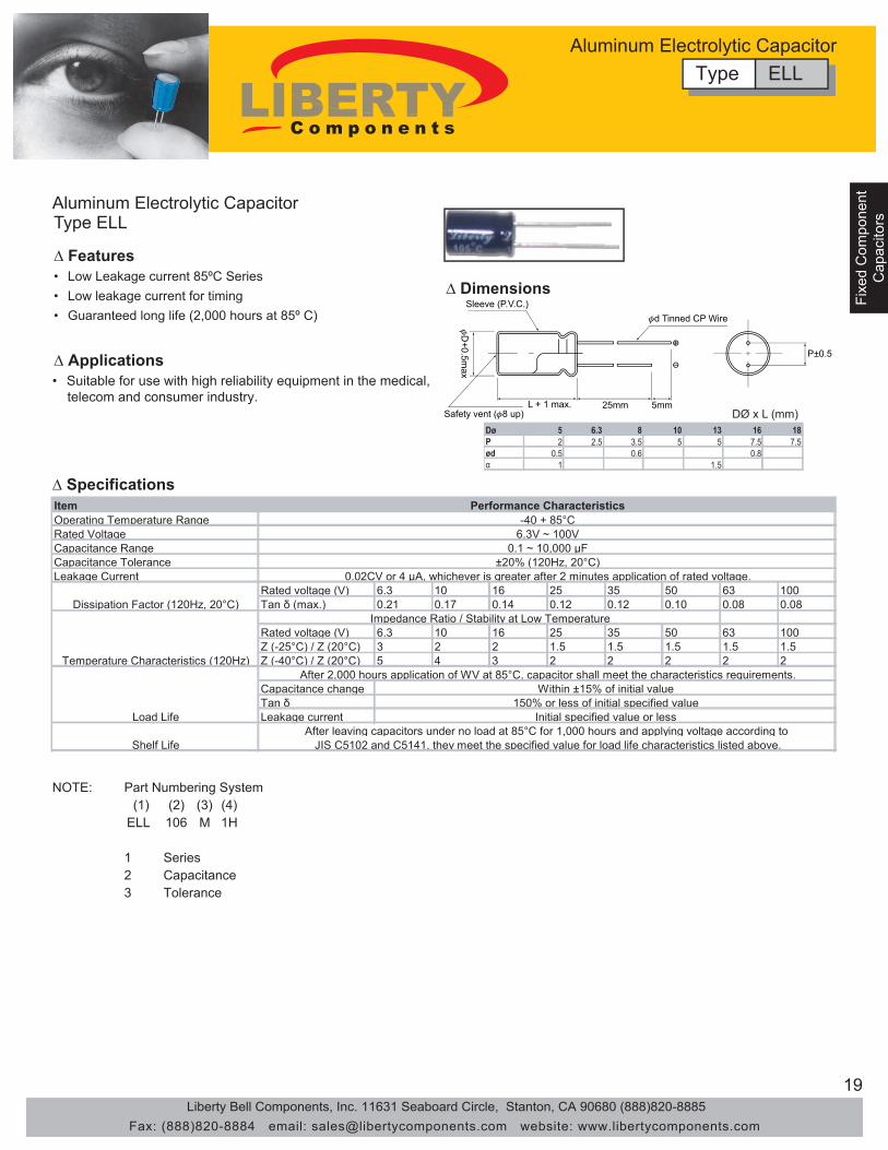
ItemOperating Temperature RangeRated VoltageCapacitance RangeCapacitance ToleranceLeakage Current
Rated voltage (V) 6.3 10 16 25 35 50 63 100Tan δ (max.) 0.21 0.17 0.14 0.12 0.12 0.10 0.08 0.08
Rated voltage (V) 6.3 10 16 25 35 50 63 100Z (-25°C) / Z (20°C) 3 2 2 1.5 1.5 1.5 1.5 1.5Z (-40°C) / Z (20°C) 5 4 3 2 2 2 2 2
Capacitance changeTan δLeakage current
Performance Characteristics
Shelf Life
Dissipation Factor (120Hz, 20°C)
Temperature Characteristics (120Hz)
Load Life
Impedance Ratio / Stability at Low Temperature
After 2,000 hours application of WV at 85°C, capacitor shall meet the characteristics requirements.Within ±15% of initial value
150% or less of initial specified value
±20% (120Hz, 20°C)0.1 ~ 10,000 μF
6.3V ~ 100V-40 + 85°C
Initial specified value or lessAfter leaving capacitors under no load at 85°C for 1,000 hours and applying voltage according to
JIS C5102 and C5141, they meet the specified value for load life characteristics listed above.
0.02CV or 4 μA, whichever is greater after 2 minutes application of rated voltage.
Dø 5 6.3 8 10 13 16 18P 2 2.5 3.5 5 5 7.5 7.5ød 0.5 0.6 0.8α 1 1.5
NOTE: (1) (2) (3) (4)
ELL 106 M 1H
123 Tolerance
Part Numbering System
SeriesCapacitance
Aluminum Electrolytic CapacitorType ELL
∆ Features• Low Leakage current 85ºC Series• Low leakage current for timing • Guaranteed long life (2,000 hours at 85º C)
∆ Applications
∆ Dimensions
∆ Specifications
Type ELLAluminum Electrolytic Capacitor
DØ x L (mm)
• Suitable for use with high reliability equipment in the medical, telecom and consumer industry.
Liberty Bell Components, Inc. 11631 Seaboard Circle, Stanton, CA 90680 (888)820-8885Fax: (888)820-8884 email: [email protected] website: www.libertycomponents.com

20
Fixed Com
ponentFixed C
omponent
Capacitors
Capacitors
Fixe
d C
ompo
nent
Cap
acito
rs
Aluminum Electrolytic CapacitorType ELL
∆ Dimensions
Type ELLAluminum Electrolytic Capacitor
Ripple current (mA) at 85°C 120Hz
Dφ x L (mm)WV(SV)
Cap (μF)6.3(10)
10(13)
16(20)
25(32)
35(44)
50(63)
63(75)
100(125)
0.1- 0.47 11 x 511 x 51 5 x 11 10 5 x 11 19
2.2 5 x 11 23 5 x 11 283.3 5 x 11 40 5 x 11 45
0511 x 55411 x 55411 x 57.40911 x 85711 x 3.60711 x 50711 x 55511 x 50163121 x 0151111 x 801111 x 3.601111 x 3.600111 x 55811 x 52208161 x 0107111 x 856111 x 804111 x 3.604111 x 3.600111 x 53302202 x 0100221 x 0109111 x 809111 x 807111 x 3.604111 x 3.601111 x 57407302 x 3103302 x 0102361 x 0100321 x 0108211 x 803211 x 808111 x 3.600108552 x 6105502 x 3109402 x 3104402 x 0100461 x 0107321 x 0101311 x 802203723 x 6101752 x 3100602 x 3105502 x 3109402 x 01024 61 x 0100421 x 01033
470 10 x 12 390 10 x 16 530 10 x 20 550 13 x 20 660 13 x 25 680 16 x 25 760 16 x 25 850 18 x 36 9101000 10 x 20 650 13 x 20 810 13 x 25 910 16 x 25 1010 16 x 25 1100 16 x 32 1140 18 x 36 13302200 13 x 25 1060 16 x 25 1200 16 x 25 1300 16 x 36 1440 18 x 36 15803300 16 x 25 1270 16 x 32 1420 16 x 36 1550 18 x 40 17204700 16 x 32 1500 16 x 36 1650 18 x 36 18206800 18 x 36 1760 18 x 36 1890 Case
sizeRipple
10000 18 x 40 1900
Liberty Bell Components, Inc. 11631 Seaboard Circle, Stanton, CA 90680 (888)820-8885Fax: (888)820-8884 email: [email protected] website: www.libertycomponents.com

21
Fixed Com
ponentC
apacitors
Fixe
d C
ompo
nent
Fixe
d C
ompo
nent
Cap
acito
rsC
apac
itors
Aluminum Electrolytic CapacitorType ESL - 7mm Height 85°C Low Leakage Series
Dø 4 5 6 8P 1.5 2.0 2.5 3.5ød 0.45 0.45 0.45 0.5
∆ Features• Low Leakage Current Series• Highly reliable electrical performance
∆ Applications• Excellent spacing with 7mm height
∆ Specifications
∆ Dimensions
ItemOperating Temperature RangeRated VoltageCapacitance RangeCapacitance ToleranceLeakage Current
Rated voltage (V) 6.3 10 16 25 35 50Tan δ (max.) 0.24 0.20 0.16 0.14 0.12 0.10
Rated voltage (V) 6.3 10 16 25 35 50Z (-25°C) / Z (20°C) 4 3 2 2 2 2Z (-40°C) / Z (20°C) 8 6 4 4 3 3
Capacitance changeTan δLeakage current
After leaving capacitors under no load at 85°C for 1,000 hours and applying voltage according to JIS C5102 and C5141, they meet the specified value for load life characteristics listed above.Shelf Life
Performance Characteristics-40 + 85°C6.3V ~ 50V
0.1 ~ 220 μF±20% (120Hz, 20°C)
Within ±20% of initial value
Initial specified value or less
I ≤ 0.01CV or 3 μA, whichever is greater after 2 minutes application of rated voltage.
After 1,000 hours application of WV at 85°C, capacitor shall meet the characteristics requirements.
Dissipation Factor (120Hz, 20°C)
Temperature Characteristics (120Hz)
Load Life
Stability at Low Temperature
200% or less of initial specified value
NOTE: (1) (2) (3) (4)
ESL 106 M 1H
1234
ToleranceWorking Voltage
Part Numbering System SeriesCapacitance
Type ESLAluminum Electrolytic Capacitor
Dφ x L (mm)
Ripple current (mA) at 85°C 120Hz
WV(SV)Cap (μF)
6.3(10)
10(13)
16(20)
25(32)
35(44)
50(63)
0.1 4 x 7 10.22 4 x 7 2.30.33 4 x 7 3.50.47 4 x 7 5
1 4 x 7 102.2 4 x 7 193.3 4 x 7 244.7 4 x 7 24 5 x 7 29
447 x 3.6637 x 5337 x 5927 x 40122 4 x 7 34 5 x 7 38 5 x 7 44 6.3 x 7 51 6.3 x 7 57 8 x 7 6533 5 x 7 42 5 x 7 47 6.3 x 7 57 6.3 x 7 63 8 x 7 7247 5 x 7 50 6.3 x 7 59 6.3 x 7 68 8 x 7 78
100 6.3 x 7 77 8 x 7 96 8 x 7 107Case Size Ripple
220 8 x 7 130
• Expected life (1,000 hours at 85º C)
Liberty Bell Components, Inc. 11631 Seaboard Circle, Stanton, CA 90680 (888)820-8885Fax: (888)820-8884 email: [email protected] website: www.libertycomponents.com

22
Fixed Com
ponentFixed C
omponent
Capacitors
Capacitors
Fixe
d C
ompo
nent
Cap
acito
rs
• Designed to withstand high ripples • Has low impedance characteristics • Guaranteed long life (2,000 ~ 3,000 hours at 105º C) • Suitable for use in high reliability switching power supply circuits.
5 6.3 8 10 13 16 18 22 25 2 2.5 3.5 5 5 7.5 7.5 10 12.5
α ~100V 160V~
0.8 1.5 2
1 2 2
1 1.5
0.6 1.5 2
Dø P ød 0.5
WV Cap(μF) \ Frequency 50Hz 120Hz 300Hz 1KHz 10KHz~ ~ 47 - 0.17 0.4 0.65 1 100 ~ 220 0.3 0.5 0.65 0.8 1 330 ~ 680 0.57 0.71 0.82 0.9 1 1000 ~ 15000 0.75 0.87 0.96 0.98 1 0.47 ~ 220 0.8 1 1.25 1.4 1.6 330 ~ 470 0.9 1 1.1 1.13 1.15 160 ~450
6.3 ~100
Aluminum Electrolytic Capacitor Type GLZ
∆ Features
∆ Specifications
∆ Applications
∆ Frequency coefficient of allowable ripple current
Item Operating Temperature Range Rated Voltage Capacitance Range Capacitance Tolerance
Dissipation Factor Rated voltage (V) 6.3 10 16 25 35 50 63 100 160~250 400~450 Tan d (max.) 0.24 0.20 0.16 0.14 0.12 0.10 0.09 0.09 0.15 0.25
Temperature Characteristics Rated voltage (V) 6.3~10 16~25 35~50 63~100 160~200 Z (-55°C) / Z (20°C) 5 4 3 - - Z (-40°C) / Z (20°C) - - - 3 4 Z (-25°C) / Z (20°C) - - - 2 3
Capacitance change Tan d Leakage current
(120Hz, 20ºC)
Shelf Life
5 ~ 6 φ : 2,000 hours 8 ~ 10 φ : 2,000 hours ≥ 13 φ : 3,000 hours Within ±20% of initial value
Load Life
(120Hz) After a certain hour application of rated voltage and ripple current at 105°C, capacitor shall meet the characteristics
requirements mentioned below.
- 15
10
450 -
400 -
0.03CV or 4 μA, whichever is greater after 2 minutes application of rated voltage.
For capacitance of more than 1,000μF, add 0.02 for every increase of 1,000μF. Impedance Ratio / Stability at Low Temperature
350 0.20
Leakage Current
Performance Characteristics -55 + 105ºC (6.3 ~ 100V) -40 + 105°C (160 ~ 400V) -25 + 105ºC (450V)
6.3V ~100V 0.47 ~ 15,000 μF
±20% (120Hz, 20°C)
CV 1000: I = 0.1CV + 40 μA max. (2 minutes) CV 1000: I = 0.4CV + 100 μA max. (2 minutes)
160V ~ 450V 6.3V ~ 100V
6
350 - 8 4
250 - 6 3
200% or less of initial specified value Initial specified value or less
After leaving capacitors under no load at 105°C for 1,000 hours and applying voltage according to JIS C5102 4-3, capacitor shall meet the specified value as load life characteristics listed above.
Type GLZAluminum Electrolytic Capacitor
DØ x L (mm)
Liberty Bell Components, Inc. 11631 Seaboard Circle, Stanton, CA 90680 (888)820-8885Fax: (888)820-8884 email: [email protected] website: www.libertycomponents.com

23
Fixed Com
ponentC
apacitors
Fixe
d C
ompo
nent
Fixe
d C
ompo
nent
Cap
acito
rsC
apac
itors
∆ Dimensions
Type GLZAluminum Electrolytic Capacitor
Dφ x L (mm)
• Impedance: (Ω) Max. 20°C 100KHz • Allowable ripple current: (mA) at 105°C 100KHz
WVCap (μF)
V52V61V01V3.6Size Imp. Ripple Size Imp. Ripple Size Imp. Ripple Size Imp. Ripple
4.7 5 x 11 1.50 16010 5 x 11 1.50 16022 5 x 11 1.50 160 5 x 11 1.50 160 5 x 11 1.50 160 5 x 11 1.50 16033 5 x 11 1.50 160 5 x 11 1.50 160 5 x 11 1.50 160 5 x 11 1.50 16047 5 x 11 1.50 160 5 x 11 1.50 160 5 x 11 1.50 160 5 x 11 1.50 160
100 5 x 11 1.50 160 5 x 11 1.50 160 6 x 11 0.50 250 6 x 11 0.50 250220 6 x 11 0.50 250 6 x 11 0.50 250 8 x 11 0.28 410 8 x 11 0.28 410330 6 x 11 0.50 250 8 x 11 0.28 410 8 x 11 0.28 410 10 x 12 0.19 600470 8 x 11 0.28 410 8 x 11 0.28 410 10 x 12 0.19 600 10 x 16 0.14 800680 10 x 12 0.19 600 10 x 12 0.19 600 10 x 16 0.14 800 10 x 20 0.11 1000
1000 10 x 12 0.19 600 10 x 16 0.14 800 10 x 20 0.11 1000 13 x 20 0.075 12501500 10 x 20 0.11 1000 10 x 20 0.11 1000 13 x 20 0.075 1250 16 x 25 0.038 19002200 13 x 20 0.075 1250 13 x 20 0.075 1250 13 x 25 0.057 1550 16 x 25 0.038 19003300 13 x 20 0.075 1250 13 x 25 0.057 1550 16 x 25 0.038 1900 16 x 31 0.033 23504700 16 x 25 0.038 1900 16 x 25 0.038 1900 16 x 31 0.033 2350 18 x 35 0.030 27006800 16 x 25 0.038 1900 16 x 31 0.033 2350 18 x 35 0.030 2700 18 x 40 0.027 330010000 16 x 31 0.033 2350 18 x 35 0.030 2700 18 x 40 0.027 330015000 18 x 35 0.030 2700 18 x 40 0.027 3300
WVCap (μF)
V001V36V05V53Size Imp. Ripple Size Imp. Ripple Size Imp. Ripple Size Imp. Ripple
020.3411 x 55205.711 x 574.0030.0211 x 50403.511 x 514408.911 x 55505.411 x 52.28506.611 x 55609.311 x 53.3
4.7 5 x 11 1.50 160 5 x 11 3.50 90 5 x 11 4.70 68 5 x 11 4.60 7410 5 x 11 1.50 160 5 x 11 2.10 120 5 x 11 2.10 110 6 x 11 1.80 13022 5 x 11 1.50 160 5 x 11 1.80 150 6 x 11 0.98 180 8 x 11 0.68 23033 5 x 11 1.50 160 6 x 11 0.65 250 6 x 11 0.71 220 10 x 12 0.46 32047 6 x 11 0.50 250 6 x 11 0.65 250 8 x 11 0.65 310 10 x 16 0.37 420
100 8 x 11 0.28 410 8 x 11 0.36 340 10 x 12 0.31 390 13 x 20 0.18 580150 8 x 11 0.28 410 10 x 12 0.26 490 10 x 16 0.25 440 13 x 25 0.13 710220 10 x 12 0.19 600 10 x 16 0.18 650 10 x 20 0.20 700 16 x 25 0.10 890330 10 x 16 0.14 800 10 x 20 0.15 810 13 x 20 0.12 980 16 x 25 0.090 1080470 10 x 20 0.11 1000 13 x 20 0.13 1100 13 x 25 0.081 1200 16 x 31 0.076 1310680 13 x 20 0.075 1250 13 x 25 0.10 1200 16 x 25 0.058 1300 16 x 35 0.064 14101000 13 x 25 0.057 1550 16 x 25 0.058 1600 16 x 31 0.049 1380 18 x 40 0.047 45201500 16 x 25 0.038 1900 16 x 31 0.040 2000 18 x 35 0.038 17502200 16 x 31 0.033 2350 18 x 35 0.035 2300 18 x 40 0.032 21203300 18 x 35 0.030 27004700 18 X 40 0.027 3300
WVCap (μF) 160V 200V 250V 350V 400V 450V
0.47 6 x 11 12 6 x 11 12 6 x 11 12 8 x 11 111 6 x 11 17 6 x 11 17 6 x 11 17 10 x 12 17 10 x 12 16 10 x 12 18
2.2 6 x 11 25 6 x 11 25 8 x 11 29 10 x 16 31 10 x 16 27 10 x 20 293.3 8 x 11 36 8 x 11 36 10 x 12 42 10 x 16 38 10 x 20 36 13 x 20 414.7 8 x 11 43 10 x 12 50 10 x 12 50 10 x 20 49 10 x 20 43 13 x 20 4910 10 x 12 70 10 x 16 80 10 x 20 88 13 x 20 82 13 x 25 72 16 x 25 7522 10 x 20 130 10 x 20 140 13 x 25 155 16 x 25 130 16 x 25 110 16 x 31 11533 13 x 20 180 13 x 25 190 13 x 25 190 16 x 31 160 16 x 31 140 18 x 35 14547 13 x 25 220 13 x 25 220 16 x 25 230 18 x 35 200 18 x 35 170 20 x 40 175
100 16 x 25 330 16 x 31 335 18 x 35 340 20 x 40 290 22 x 50 350 25 x 50 350220 18 x 35 500 18 x 40 515 20 x 40 525 25 x 50 550330 20 x 40 900 22 x 40 1100 22 x 50 1150
Case Size Ripple470 22 x 50 1200 22x 50 1310 25 x 50 1350
• Allowable ripple current (mA) at 105°C 120Hz
Liberty Bell Components, Inc. 11631 Seaboard Circle, Stanton, CA 90680 (888)820-8885Fax: (888)820-8884 email: [email protected] website: www.libertycomponents.com

24
Fixed Com
ponentFixed C
omponent
Capacitors
Capacitors
Fixe
d C
ompo
nent
Cap
acito
rs
Electric Double Layer Capacitor Type DB
∆ Features • Small size, large capacity, excellent voltage holding • Uniform 5mm Pitch of terminal spacing • Wider temperature range (-25 ~ +70º C) than battery makes periodic changes unnecessary
NOTE: (1) (2) (3) (4)
DB 106 M 1H
1 2 3 4
Tolerance Working Voltage
Part Numbering System
Series Capacitance
∆ Applications
∆ Specifications
• Ideal for backing up of CMOS’s, Microcomputers, RAM’s and the like used in VCR’s, tuners, TV sets, Telephone sets and others
Rated Voltage (V) Rated Capacitance (F) ΦDxL(mm) 5.5 0.047 13.5x7.5 5.5 0.1 13.5x7.5 5.5 0.22 13.5x7.5 5.5 0.33 13.5x7.5 5.5 0.47 21.5x8.0 5.5 1.0 21.5x8.0
∆ Standard Ratings
L Max 6.0±1
5.0±
0.3
5.0±
0.1
Sleeve
Φ DMax
1.2±0.1
0.8±0.1
6.0±
1
Unit: mm
Item Category temperature
range (°C) Tolerance at rated capacitance (%)
Rated Capacitance (F) 0.047 0.1 0.22 0.33 0.47 1.0 Internal Resistance (Ω) 120 75 75 75 30 30 Percentage of Capacitance Change Internal Resistance Test time Percentage of capcitance change Internal Resistance
Shelf Life (70°)
Internal resistance at 1kHz
Characteristics at high and low temp
Within ±30% of value at 20°C Less than five times the value at 20°C
Test time: 1000 hours ; same as endurance
Performance
-25 to +70
-20 to +80
1000 hours Within ±30% of the initial measure value
Within four times the initial specified value Endurance
Type DBElectric Double Layer Capacitor
Liberty Bell Components, Inc. 11631 Seaboard Circle, Stanton, CA 90680 (888)820-8885Fax: (888)820-8884 email: [email protected] website: www.libertycomponents.com

25
Fixed Com
ponentC
apacitors
Fixe
d C
ompo
nent
Fixe
d C
ompo
nent
Cap
acito
rsC
apac
itors
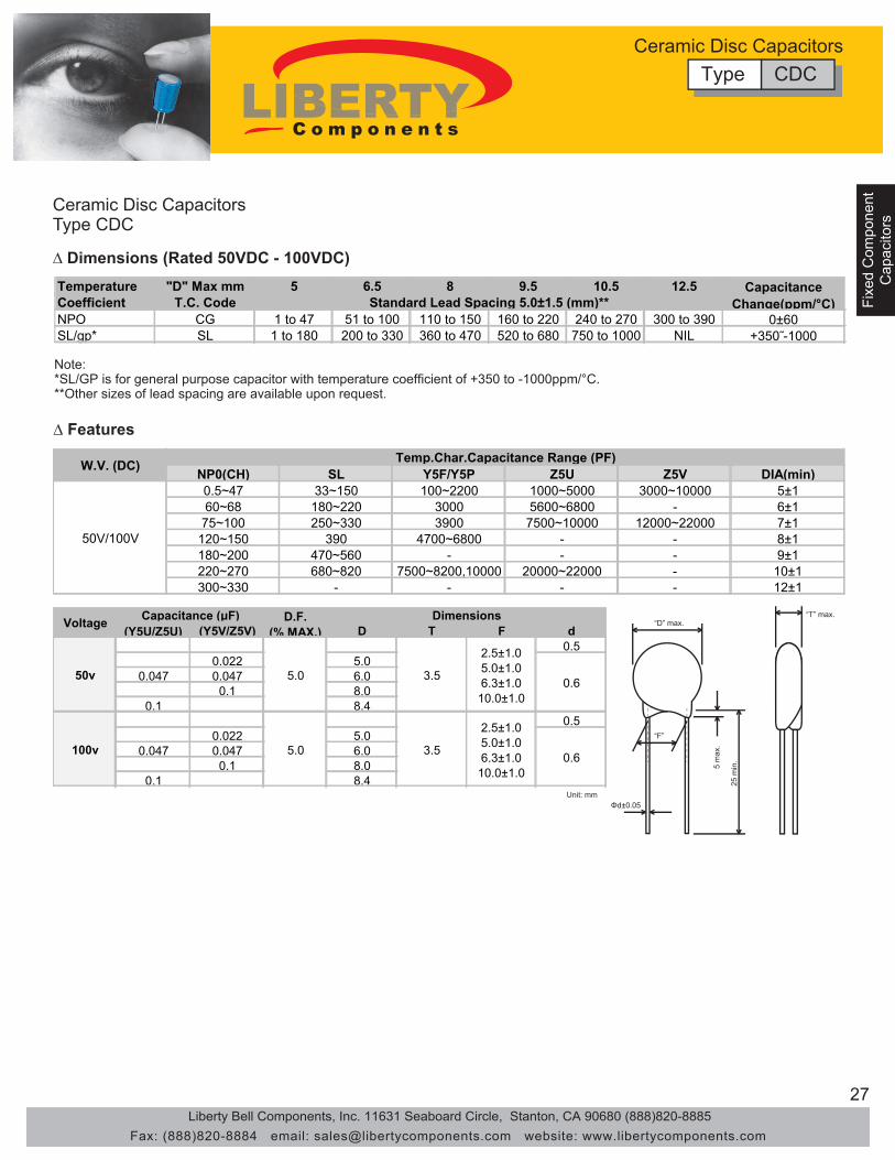
Type CDCCeramic Disc Capacitors
Ceramic Disc Capacitors
∆ Features Linear temperature coefficient of capacitance. High stability of capacitance.
• •
Type CDC
Low loss at wide range of frequency. •
∆ ApplicationsTemperature compensation of resonant circuit and filters•Where low losses and high stability of capacitancetolerance and high insulation resistance are required.
•
(1) Type(2) Nominal Capacitance(3) Temperature Characteristics(4) Rated Voltage(5) Capacitance Tolerance(6) Lead type (Omitted in straight leads)(7) Suffix (Omitted in bulk package)
∆ Part Numbering
CDC 101 CG 1H K □ □(1) (2) (3) (4) (5) (6) (7)
(2) Nominal Capacitance DesignationStated in three digits and in units of pico farads (pF).The capacitance shall be expressed in a 3 digit code.The first and second digits identify the first and secondsignificant figures of the capacitance, the third digitidentifies the multiplier. However, when capacitance isbelow 10pF there are decimal digits included, they arestated as D. Please check examples below:
(3) Temperature Characteristics
SymbolD75 0.755D0 5.0100 10101 100
Capacitance (pF)
(4) Rated Voltage
Symbol Tolerance Capacitance RangeK ±10%M ±20%
(5) Capacitance Tolerance (6) Lead Type
(7) Suffix
Use the letter “C” when crimped leads are needed.
Use the letter “T” when taped/box packages are needed.
Other nonstandard values are available on special request.
CodeTemp. RangeTemp. Coeff.
Code Y5F(YF)/Y5P(YP) Y5V(YV)/Z5V(ZV) Y5U(YU)/Z5U(ZU)Temp. Range -25°C to 85°C -25°C to 85°C -25°C to 85°CTemp. Coeff. ±10% +20% to -30% +20% to -55%
Class I (Temperature Compensating Type)
Class II (High Dielectric Type)
SL/GP-25°C to 105°C
+350ppm to -1000ppm/°C
Symbol VDC1H 50 50V2A 100 100V2H 500 500V3A 1000 1kV
Rated Voltage
Liberty Bell Components, Inc. 11631 Seaboard Circle, Stanton, CA 90680 (888)820-8885Fax: (888)820-8884 email: [email protected] website: www.libertycomponents.com

26
Fixed Com
ponentFixed C
omponent
Capacitors
Capacitors
Fixe
d C
ompo
nent
Cap
acito
rs
Ceramic Disc CapacitorsType CDC
∆ Electrical Specifications (Class I, T.C. Type)
∆ Electrical Specifications (Class II High-K Type)
Type CDCCeramic Disc Capacitors
ItemOperating Temp. RangeRated VoltageDielectric Withstanding Voltage
±0.25pF (1 to 5pF)±0.50pF (1 to 10pF)±1pF (10pF)±5% (Over 10pF E24 series)±10% (Over 10pF E24 series)
Insulation Resistance
NPO SL∆C 1 to 2 ±250 +350
C20 X ∆T 3 ±120 to4 & Up ±60 -1000
Temperature Coefficient of Capacitance
Temperature Range: -25°C to +85°CReference Temperature: 20°C
T.C. =
Measured at the rated voltage and 1 Minute Electrification
I.R. ≥ 10,000MΩ
Temperature coefficient tolerance
Capacitance (pF) Rated temperature coefficient (ppm/°C)
Cap. <30pF: Q≥400+20 X C (C:Rated capacitance in pF)Cap. ≥30pF: Q≥1000
Measured at 1MHz, 5Vrms Max. and 20°C
Q-Factor
Capacitance
Within the specified toleranceStandard capacitance tolerance
Test Method Requirements
250% of the rated voltage for 1 to 5 seconds
-25°C to +85°C
50VDC - 100VDC
No damage occurs when the test voltage is applied between terminals
ItemOperating Temp. RangeRated VoltageDielectric Withstanding Voltage
[Y5F/Y5P]: ±10% (In E-12 Series)[Y5T]: ±20% (In E-6 Series)[Y5U/Z5U]: ±20% (In E-6 Series)[Y5V/Z5V]: +80%, -20% (In E-3 Series)
tan φ ≤2.5%tan φ ≤5.0%
∆CC20 Temp. Char. Max. Cap. Change Temp. Range
Y5F/Y5P ±10% -25°C ~ +85°CY5T +20% ~ -30% -25°C ~ +85°CY5U/Z5U +20% ~ -55% -10°C ~ +85°CY5V +30% ~ -80% -25°C ~ +85°CZ5V +30% ~ -80% +10°C ~ +85°C
Standard capacitance tolerance
Test Method Requirements
250% of the rated voltage for 1 to 5 seconds
-25°C to +85°C
25VDC - 500VDC
No damage occurs when the test voltage is applied between terminals
C20: Capacitance Value in pF at the specified reference temperature of 20°C
Cap. ≤ 0.02μF: I.R.≥ 10000MΩCap.> 0.02μF: CR products ≥200MΩ · μF
Temperature Coefficient of Capacitance
Measured at 1MHz, 5Vrms Max. and 20°C
Dissipation Factor (tan φ)
Capacitance
Within the specified tolerance
[Y5F/Y5P,Y5T,Y5U/Z5U]:[Y5V/Z5V]:
Capacitance Change =
Insulation Resistance
Measured at the rated voltage and 1 Minute Electrification
X 100%
∆C: Capacitance drifts in the pF from the capacitance value ato 20°C over the specified temperature range
Liberty Bell Components, Inc. 11631 Seaboard Circle, Stanton, CA 90680 (888)820-8885Fax: (888)820-8884 email: [email protected] website: www.libertycomponents.com
27
Fixed Com
ponentC
apacitors
Fixe
d C
ompo
nent
Fixe
d C
ompo
nent
Cap
acito
rsC
apac
itors
Ceramic Disc Capacitors
∆ Features
Type CDC
Type CDCCeramic Disc Capacitors
NP0(CH) SL Y5F/Y5P Z5U Z5V DIA(min)0.5~47 33~150 100~2200 1000~5000 3000~10000 5±160~68 180~220 3000 5600~6800 - 6±1
75~100 250~330 3900 7500~10000 12000~22000 7±1120~150 390 4700~6800 - - 8±1180~200 470~560 - - - 9±1220~270 680~820 7500~8200,10000 20000~22000 - 10±1300~330 - - - - 12±1
W.V. (DC) Temp.Char.Capacitance Range (PF)
50V/100V
“D” max.
“F”
“T” max.
5 m
ax.
25 m
in.
Φd±0.05Unit: mm
(Y5U/Z5U) (Y5V/Z5V) D T F d0.5
0.022 5.00.047 0.047 6.0
0.1 8.00.1 8.4
0.50.022 5.0
0.047 0.047 6.00.1 8.0
0.1 8.4
D.F.(% MAX.)
Capacitance (μF) Dimensions
100v
50v
2.5±1.0 5.0±1.0 6.3±1.0 10.0±1.0
0.6
2.5±1.0 5.0±1.0 6.3±1.0 10.0±1.0
0.6
5.0
5.0
3.5
3.5
Voltage
∆ Dimensions (Rated 50VDC - 100VDC)
Note:*SL/GP is for general purpose capacitor with temperature coefficient of +350 to -1000ppm/°C.**Other sizes of lead spacing are available upon request.
Temperature "D" Max mm 5 6.5 8 9.5 10.5 12.5Coefficient T.C. CodeNPO CG 1 to 47 51 to 100 110 to 150 160 to 220 240 to 270 300 to 390 0±60SL/gp* SL 1 to 180 200 to 330 360 to 470 520 to 680 750 to 1000 NIL +350˜-1000
Standard Lead Spacing 5.0±1.5 (mm)**Capacitance
Change(ppm/°C)
Liberty Bell Components, Inc. 11631 Seaboard Circle, Stanton, CA 90680 (888)820-8885Fax: (888)820-8884 email: [email protected] website: www.libertycomponents.com

28
Fixed Com
ponentFixed C
omponent
Capacitors
Capacitors
Fixe
d C
ompo
nent
Cap
acito
rs
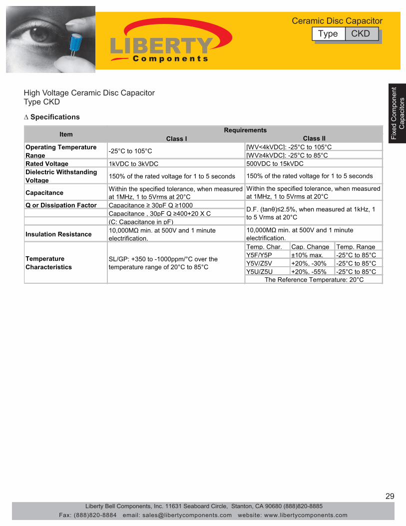
High Voltage Ceramic Disc Capacitor
∆ Features Wide operating temperature range: -25°C to 125°C Two kinds of Capacitors for “DC circuit use” and Pulse Circuit Use” are available
•
Low loss at wide range of frequency and stable against pulse voltage Miniaturized type applying new ceramic dielectrics Flame retardent insulating coating applied
•
•
• •
∆ Applications DC and pulse high voltage circuit • Resonance circuit in F.B.T. with inductor for TV set Snubber circuit of switching power supply
• •
(1) Type (2) Nominal Capacitance (3) Temperature Characteristics (4) Rated Voltage (5) Capacitance Tolerance (6) Lead type (Omitted in straight leads) (7) Suffix (Omitted in bulk package)
∆ Part Numbering
CKD 101 YF 3A K □ □ (1) (2) (3) (4) (5) (6) (7)
(2) Nominal Capacitance Designation Stated in three digits and in units of pico farads (pF). The capacitance shall be expressed in a 3 digit code. The first and second digits identify the first and second significant figures of the capacitance, the third digit identifies the multiplier. However, when capacitance is below 10pF there are decimal digits included, they are stated as D. Please check examples below:
Type CKD
(3) Temperature Characteristics
Symbol D75 0.75 5D0 5.0 100 10 101 100
Capacitance (pF)
(4) Rated Voltage Symbol VDC 2H 500 500V 3A 1000 1kV 3D 2000 2kV 3F 3000 3kV 3G 4000 4kV 3J 6000 6kV 3K 8000 8kV 4A 10000 10kV 4C 15000 15kV
Rated Voltage
Symbol Tolerance Capacitance RangeK ±10%M ±20%
(5) Capacitance Tolerance (6) Lead Type
(7) Suffix
Use the letter “C” when crimped leads are needed.
Use the letter “T” when taped/box packages are needed.
Other nonstandard values are available on special request.
Type CKDCeramic Disc Capacitor
CodeTemp. RangeTemp. Coeff.
Code Y5F(YF)/Y5P(YP) Y5V(YV)/Z5V(ZV) Y5U(YU)/Z5U(ZU)Temp. Range -25°C to 85°C -25°C to 85°C -25°C to 85°CTemp. Coeff. ±10% +20% to -30% +20% to -55%
Class I (Temperature Compensating Type)
Class II (High Dielectric Type)
SL/GP-25°C to 105°C
+350ppm to -1000ppm/°C
Liberty Bell Components, Inc. 11631 Seaboard Circle, Stanton, CA 90680 (888)820-8885Fax: (888)820-8884 email: [email protected] website: www.libertycomponents.com
29
Fixed Com
ponentC
apacitors
Fixe
d C
ompo
nent
Fixe
d C
ompo
nent
Cap
acito
rsC
apac
itors
High Voltage Ceramic Disc Capacitor
∆ Specifications
Type CKD
Type CKDCeramic Disc Capacitor
Class I
Rated Voltage 1kVDC to 3kVDCDielectric Withstanding Voltage 150% of the rated voltage for 1 to 5 seconds
Capacitance Within the specified tolerance, when measured at 1MHz, 1 to 5Vrms at 20°C
Q or Dissipation Factor Capacitance ≥ 30pF Q ≥1000Capacitance , 30pF Q ≥400+20 X C(C: Capacitance in pF)
Insulation Resistance 10,000MΩ min. at 500V and 1 minute electrification.
Temp. Char. Cap. Change Temp. RangeY5F/Y5P ±10% max. -25°C to 85°CY5V/Z5V +20%, -30% -25°C to 85°CY5U/Z5U +20%, -55% -25°C to 85°C
[WV≥4kVDC]: -25°C to 85°C500VDC to 15kVDC
150% of the rated voltage for 1 to 5 seconds
Within the specified tolerance, when measured at 1MHz, 1 to 5Vrms at 20°C
D.F. (tanθ)≤2.5%, when measured at 1kHz, 1 to 5 Vrms at 20°C
Item Requirements
10,000MΩ min. at 500V and 1 minute electrification.
SL/GP: +350 to -1000ppm/°C over the temperature range of 20°C to 85°C
Temperature Characteristics
The Reference Temperature: 20°C
Operating Temperature Range
-25°C to 105°C
Class II[WV<4kVDC]: -25°C to 105°C
Liberty Bell Components, Inc. 11631 Seaboard Circle, Stanton, CA 90680 (888)820-8885Fax: (888)820-8884 email: [email protected] website: www.libertycomponents.com

30
Fixed Com
ponentFixed C
omponent
Capacitors
Capacitors
Fixe
d C
ompo
nent
Cap
acito
rs
∆ Capacitance Chart
High Voltage Ceramic Disc Capacitor Type CKD
Type CKDCeramic Disc Capacitor
“D” max.
“F”
“T” max.
5 m
ax.
25 m
in.
Φd±0.05
Disc Dia.mm (in.)
D ± 2 T max.(± 0.079) 1000V 2000V 3000V 1000V 2000V 3000V 4000V 5000V 1000V 2000V 3000V
4.0(0.157)
3.0(0.118) 100-270 100-150 100-150 330-680 - - - - 820-1200 - -
5.0(0.197)
4.0(0.157) 330-470 180-270 100-150 820-1200 330-470 - - - 1500 - -
6.0(0.236)
4.0(0.157) 560 330 180 1500 560-820 - - - 1800 1000-1200 -
7.0(0.276)
4.0(0.157) 680-1200 390-560 220-330 1800-2700 1000-1500 390-1000 - - 2200-3900 1500-2200 1200-1500
8.0(0.315)
4.0(0.157) 1500 680-820 390-560 3300-3900 1800 1200 100-820 - - 2700 1800
9.0(0.354)
5.0(0.197) 1800 1000-1200 680 4700 2200-2700 1500-1800 - - 4700-5600 3300-3900 2200-2700
10.0(.394)
5.0(0.197) - 1500 820-1000 5600 3300-3900 2200 1000 - 6800-8200 - -
11.0(0.433)
5.0(0.197) 2200-2700 1800 1200 6800 4700 2700-3300 1200-2200 100-1000 - 4700-6800 3300-3900
13.0(0.512)
6.0(0.236) 3300 2200-2700 1500-1800 8200-12000 5600-8200 3900-5600 2700-3300 1200-2200 10000-15000 8200 4700-6800
15.0(0.591)
6.0(0.236) 3900 3300-3900 2200-2700 15000 10000 6800 3900-4700 2700-3300 22000 10000-
15000 8200
19.0(0.748)
7.0(0.276) - - 3300-3900 - - 8200-10000 5600-6800 3900-4700 - - 10000
Y5F (Y5P) (Y5U/Z5U) (Y5V/Z5V)Available Capacitance Range, pF
Liberty Bell Components, Inc. 11631 Seaboard Circle, Stanton, CA 90680 (888)820-8885Fax: (888)820-8884 email: [email protected] website: www.libertycomponents.com

31
Fixed Com
ponentC
apacitors
Fixe
d C
ompo
nent
Fixe
d C
ompo
nent
Cap
acito
rsC
apac
itors
∆ Capacitance Chart
High Voltage Ceramic Disc Capacitor Type CKD
Type CKDCeramic Disc Capacitor
Liberty Bell Components, Inc. 11631 Seaboard Circle, Stanton, CA 90680 (888)820-8885Fax: (888)820-8884 email: [email protected] website: www.libertycomponents.com
W.V. DIA(DC) NPO(CH) SL B(Y5P)(Y5E) E(Z5U) F(Z5V) (mm)
1~18 15~47 100~470 1000~1200 1800~2200 6±120~30 50~68 680~820 1500 2700~3300 7±133~39 82~100 1000 1800~2000 3900 8±147~56 120 1200 2200~2700 4700~5600 9±162~68 150~180 1500 3000~3300 10±172~82 200~220 1800 6800~8200 11±1
90~100 270 2000~2200 3900~4700 10000 12±1110~120 300~330 13±1
150 2700~3300 5000~6800 14±1
W.V. DIA(DC) SL Y5P E(Z5U) (mm)
5~22 100~330 6±127~39 390~500 7±147~56 560~680 1000 8±1
68 9±182 820 1500 10±1
2200 11±1100~120 1000 12±1
1500 13±1150 14±1
3300 15±1
W.V. DIA(DC) B(Y5P) (mm)
100~120 7±1150~180 8±1200~220 10±1270~330 12±1470~560 13±1
680 14±1
10KV
TEMP.CHAR./CAPACITANCE RANGE(PF)
TEMP.CHAR./CAPACITANCE RANGE(PF)
TEMP.CHAR./CAPACITANCE RANGE(PF)
3KV
6KV

32
Fixed Com
ponentFixed C
omponent
Capacitors
Capacitors
Fixe
d C
ompo
nent
Cap
acito
rs
Ceramic Disc CapacitorTemperature Characteristics
Ceramic Disc Capacitor
B (Y5F/Y5P)
Liberty Bell Components, Inc. 11631 Seaboard Circle, Stanton, CA 90680 (888)820-8885Fax: (888)820-8884 email: [email protected] website: www.libertycomponents.com
N80N150
N330N470
N220

33
Fixed Com
ponentC
apacitors
Fixe
d C
ompo
nent
Fixe
d C
ompo
nent
Cap
acito
rsC
apac
itors
Style 1 Style 2 Style 3 Style 4 Style 5 Style 6 Style 7
3 max. (500V) 4 max. (HI-Volt)
2 max. (500V)
1 max.
1 max.
23 m
in.
23 m
in.
23 m
in.
5 max. 5 max.
5 max. 5 max.
5 max.
F F: 5.0 ± 0.8 6.35 ± 0.8 10 ± 0.8
F F: 5.0 ± 0.8
F F: 5.0 ± 0.8 6.35 ± 0.8 10 ± 0.8
F F: 5.0 ± 0.8 10 ± 0.8
5 max.
5 max.
Taping Lead Taping Capacitors For Automatic Insertion
* For Ceramic Disc (Multilayer) Only 16mm
P
P
P P P P
P P P
F
D D
D D d d
P
L
H
H
H1 H
H0 H
L
W
Symbol D d P P0 P1 P2 F H H0 H1 D0 W L t
Value Max 11.0 0.6 12.7 12.7 3.85 6.35 5.0 16.0 20.0 16.0 Max 32.25 4.0 18.0 Max 11.0 0.7
Tolerance - 0.06 - 0.05 ±1 ±0.2 ±0.7 ±1 +0.8 -0.2 +1.5 -1.0 ±0.5 - ±0.2 ±0.5 - ±0.2
CASSETTE
REEL
Φ 370mm MAX.
30mm ± 1.0 MAX.
340mm MAX.
240mm MAX.
52.4 ± 1.0
5.08 ± 0.4
6.0 ± 1.0
25.0 min Lmax Dmax
0.5 ± 0.05 (Unit: mm)
Axial Type
∆ Dimensions
Ceramic Disc Capacitor
Liberty Bell Components, Inc. 11631 Seaboard Circle, Stanton, CA 90680 (888)820-8885Fax: (888)820-8884 email: [email protected] website: www.libertycomponents.com
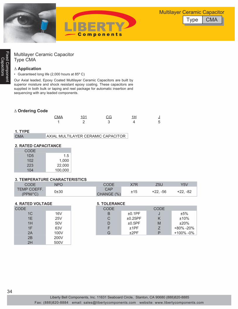
34
Fixed Com
ponentFixed C
omponent
Capacitors
Capacitors
Fixe
d C
ompo
nent
Cap
acito
rs
Multilayer Ceramic Capacitor Type CMA
∆ Application
∆ Ordering Code
• Guaranteed long life (2,000 hours at 85º C)
Our Axial leaded, Epoxy Coated Multilayer Ceramic Capacitors are built by superior moisture and shock resistant epoxy coating. These capacitors are supplied in both bulk or taping and reel package for automatic insertion and sequencing with any leaded components.
CMA 101 CG 1H J 1 2 3 4 5
1. TYPE CMA
CODE 1D5 1.5 102 1,000 223 22,000 104 100,000
CODE NPO CODE X7R Z5U Y5V
CODE CODE CODE 1C 16V B ±0.1PF J ±5% 1E 25V C ±0.25PF K ±10% 1H 50V D ±0.5PF M ±20% 1F 63V F ±1PF Z +80% -20% 2A 100V G ±2PF P +100% -0% 2B 200V 2H 500V
4. RATED VOLTAGE 5. TOLERANCE
+22, -56 +22, -82
3. TEMPERATURE CHARACTERISTICS
AXIAL MULTILAYER CERAMIC CAPACITOR
2. RATED CAPACITANCE
TEMP COEFF. (PPM/°C)
CAP CHANGE (%) 0±30 ±15
Type CMAMultilayer Ceramic Capacitor
Liberty Bell Components, Inc. 11631 Seaboard Circle, Stanton, CA 90680 (888)820-8885Fax: (888)820-8884 email: [email protected] website: www.libertycomponents.com

35
Fixed Com
ponentC
apacitors
Fixe
d C
ompo
nent
Fixe
d C
ompo
nent
Cap
acito
rsC
apac
itors
Multilayer Ceramic Capacitor Type CMA
∆ Application
R15 R18 R15 R18 50 100 50 100 50 100 50 100
1-100pF 1-100pF 120 121 150 151 180 181 220 221 270 271 330 331 390 391 470 471 560 561 680 681 820 821 1000 102 1200 122 1500 152 1800 182 2200 222 2700 272 3300 332 3900 392 4700 472 5600 562 6800 682 8200 822 0.01uF 103 0.012 123 0.015 153 0.018 183 0.022 223 0.027 273 0.033 333 0.039 393 0.047 473 0.056 563 0.068 683 0.082 823 0.10 104 0.12 124 0.15 154 0.18 184 0.22 224 0.33 334 0.47 474 0.56 564 0.68 684 0.82 824 1.0 105 1.5 155 2.2 225
CAP / WVDC
Spec.\\T.C. Size
NPO R15 R18
X7R Z5U Y5V R15 R18
50 50
Not Available Available
Type CMAMultilayer Ceramic Capacitor
Liberty Bell Components, Inc. 11631 Seaboard Circle, Stanton, CA 90680 (888)820-8885Fax: (888)820-8884 email: [email protected] website: www.libertycomponents.com

36
Fixed Com
ponentFixed C
omponent
Capacitors
Capacitors
Fixe
d C
ompo
nent
Cap
acito
rs
Multilayer Ceramic Capacitor Type CMA
∆ Dimensions
∆ Packaging Quantity
Description Symbol Dimensions in [mm]Pitch of Component P 0.200±0.020 [5.08±0.51] Cumulative Tolerance of P over 5 consecutive units ±0.0059 [±0.15] Tape Width Wt 0.236±0.039 [6.0±1.0] Lead Wire Protrusion Le 0.236±0.039 [6.0±1.0] Lead Extensions into Tape Li 0.062 max [0.8] Offset Between Tapes ∆T 0.031 max [0.8] Width Between Tapes Wt 2.06±0.062 [52.37±1.57] Pilot Hole DIA H1 0.315 [8.0] Centered C ±0.030 [±0.76] Core Diameter D1 1.3756-3.260 [34.90-92.10] Reel Diameter D2 14 max [355.60] Core Width W1 2.750±0.060 [69.85±1.52] Recess Width R 0.374 min [9.5] Arbor Hole Ho 0.510-0.608 [15.5-18.0] Deflection From Nominal Position ∆H 0.074 max [1.19] Leader Option L 12 min [304.8]
Bulk Type Quanity/Reel Quantity/Box Quantity/Bag
R15 8,000 5,000 1,000 R20 8,000 5,000 1,000
Taping Type Size Code
Type CMAMultilayer Ceramic Capacitor
Liberty Bell Components, Inc. 11631 Seaboard Circle, Stanton, CA 90680 (888)820-8885Fax: (888)820-8884 email: [email protected] website: www.libertycomponents.com
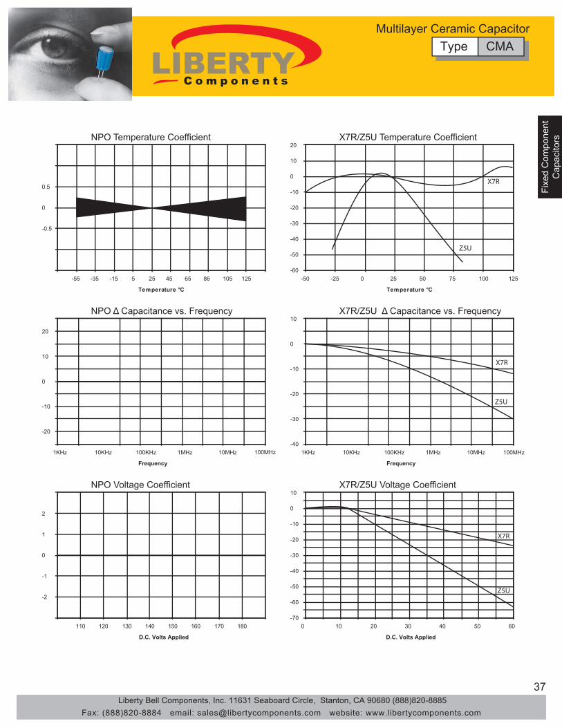
37
Fixed Com
ponentC
apacitors
Fixe
d C
ompo
nent
Fixe
d C
ompo
nent
Cap
acito
rsC
apac
itors
-0.5
0
0.5
-55 -35 -15 5 25 45 65 86 105 125
Temperature °C
-60
-50
-40
-30
-20
-10
0
10
20
-50 -25 0 25 50 75 100 125
Temperature °C
-20
-10
0
10
20
1KHz 10KHz 100KHz 1MHz 10MHz 100MHz
Frequency
-40
-30
-20
-10
0
10
1KHz 10KHz 100KHz 1MHz 10MHz 100MHz
Frequency
-2
-1
0
1
2
110 120 130 140 150 160 170 180
D.C. Volts Applied
-70 -60 -50 -40 -30 -20 -10 0 10
0 10 20 30 40 50 60
D.C. Volts Applied
X7R
Z5U
X7R
Z5U
X7R
Z5U
NPO Temperature Coefficient X7R/Z5U Temperature Coefficient
NPO Δ Capacitance vs. Frequency X7R/Z5U Δ Capacitance vs. Frequency
NPO Voltage Coefficient X7R/Z5U Voltage Coefficient
Type CMAMultilayer Ceramic Capacitor
Liberty Bell Components, Inc. 11631 Seaboard Circle, Stanton, CA 90680 (888)820-8885Fax: (888)820-8884 email: [email protected] website: www.libertycomponents.com
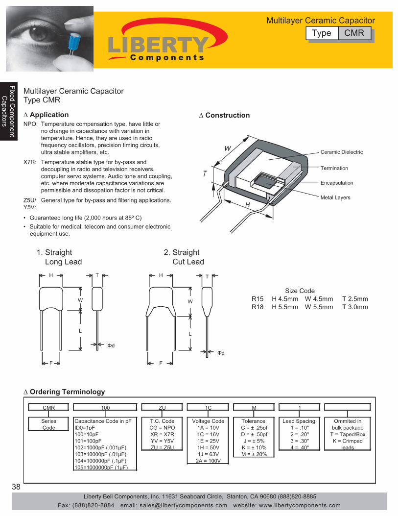
38
Fixed Com
ponentFixed C
omponent
Capacitors
Capacitors
Fixe
d C
ompo
nent
Cap
acito
rs
1. Straight Long Lead
2. Straight Cut Lead
∆ Ordering Terminology
M 1 CMR 100 ZU 1C
103=10000pF (.01μF)
Series Capacitance Code in pF ID0=1pF Code
104=100000pF (.1μF) 105=1000000pF (1μF)
T.C. Code CG = NPO XR = X7R YV = Y5V ZU = Z5U
100=10pF 101=100pF 102=1000pF (.001μF)
Voltage Code 1A = 10V 1C = 16V 1E = 25V
Tolerance: C = ± .25pf D = ± .50pf J = ± 5% 3 = .30"
1H = 50V 1J = 63V
2A = 100V
K = ± 10% M = ± 20%
4 = .40"
Ommited in bulk package
T = Taped/Box K = Crimped
leads
Lead Spacing: 1 = .10" 2 = .20"
Multilayer Ceramic Capacitor Type CMR
∆ Application ∆ Construction NPO:
Ceramic Dielectric
Termination
Encapsulation
Metal Layers
Temperature compensation type, have little or no change in capacitance with variation in temperature. Hence, they are used in radio frequency oscillators, precision timing circuits, ultra stable amplifiers, etc.
• Guaranteed long life (2,000 hours at 85º C) • Suitable for medical, telecom and consumer electronic equipment use.
X7R: Temperature stable type for by-pass and decoupling in radio and television receivers, computer servo systems. Audio tone and coupling, etc. where moderate capacitance variations are permissible and dissopation factor is not critical.
Z5U/ Y5V:
General type for by-pass and filtering applications.
H H T
W
L
W
L
F F
Φd
T
Φd
R15 H 4.5mm W 4.5mm T 2.5mm R18 H 5.5mm W 5.5mm T 3.0mm
Size Code
Type CMRMultilayer Ceramic Capacitor
Liberty Bell Components, Inc. 11631 Seaboard Circle, Stanton, CA 90680 (888)820-8885Fax: (888)820-8884 email: [email protected] website: www.libertycomponents.com

39
Fixed Com
ponentC
apacitors
Fixe
d C
ompo
nent
Fixe
d C
ompo
nent
Cap
acito
rsC
apac
itors
Multilayer Ceramic Capacitor Type CMR
∆ Specifications Temperature coefficient
NPO: ±30ppm/°C, -55°C to +125°C •
Capacitance test 25°C NPO: 1 VRMS max at 1KHz (1MHz for 100pF or less) •
Dissipation Factor 25°C NPO: 0.15% max a 1KHz, 1VRMS max (1MHz for 1000pF or less) Z5U: 5% max (at 1KHz, 1VRMS max) X7R: (at 1KHz, 1VRMS max) Max 2.5% 3.5% 5.0%
Rated Voltage ≥50V 25V & 16V 10V & 6.3V
Max 5% 7% 10%
Rated Voltage ≥50V 25V & 16V 10V & 6.3V
Y5V: (at 1KHz, 1VRMS max)
X7R: 1 VRMS max at 1KHz • Z5U: 1 VRMS max at 1KHz • Y5V: 1 VRMS max at 1KHz •
X7R: ±15%, -55°C to +125°C • Z5U: +22%, -56%, +10°C to +85°C • Y5V: ±22%, -82%, -30°C to +85°C •
Dielectric strength 25°C (Flash Test) NPO and X7R: 300% rated voltage for 5 seconds with 50mA max charging current.
•
Z5U and Y5V: 250% rated voltage for 5 seconds with 50mA max charging current.
•
LifeTest: (1000hrs at max temp. applied with Flash test voltage Recovery: 6-24hrs for NPO and 24±2hrs for X7R & Z5U)
NPO: ≤ ±3% at 200% rated voltage, 125°C • X7R: ≤ ±3% at 200% rated voltage, 125°C • Z5U: ≤ ±3% at 200% rated voltage, 85°C • Y5V: ≤ ±3% at 200% rated voltage, 85°C •
Insulation Resistance after 60 sec., charging at rated voltage, 25°C, 55% R.H. max
NPO: 100GΩ or 1000MΩ-uF whichever is less • X7R: 10GΩ or 100MΩ-uF whichever is less • Z5U: 10GΩ or 100MΩ-uF whichever is less • Y5V: 10GΩ or 1000MΩ-uF whichever is less •
Type CMRMultilayer Ceramic Capacitor
Liberty Bell Components, Inc. 11631 Seaboard Circle, Stanton, CA 90680 (888)820-8885Fax: (888)820-8884 email: [email protected] website: www.libertycomponents.com

40
Fixed Com
ponentFixed C
omponent
Capacitors
Capacitors
Fixe
d C
ompo
nent
Cap
acito
rs
-0.5
0
0.5
-55 -35 -15 5 25 45 65 86 105 125
Temperature °C
-60
-50
-40
-30
-20
-10
0
10
20
-50 -25 0 25 50 75 100 125
Temperature °C
-20
-10
0
10
20
1KHz 10KHz 100KHz 1MHz 10MHz 100MHz
Frequency
-40
-30
-20
-10
0
10
1KHz 10KHz 100KHz 1MHz 10MHz 100MHz
Frequency
-2
-1
0
1
2
110 120 130 140 150 160 170 180
D.C. Volts Applied
-70 -60 -50 -40 -30 -20 -10 0 10
0 10 20 30 40 50 60
D.C. Volts Applied
X7R
Z5U
X7R
Z5U
X7R
Z5U
NPO Temperature Coefficient X7R/Z5U Temperature Coefficient
NPO Δ Capacitance vs. Frequency X7R/Z5U Δ Capacitance vs. Frequency
NPO Voltage Coefficient X7R/Z5U Voltage Coefficient
Type CMRMultilayer Ceramic Capacitor
Liberty Bell Components, Inc. 11631 Seaboard Circle, Stanton, CA 90680 (888)820-8885Fax: (888)820-8884 email: [email protected] website: www.libertycomponents.com

41
Fixed Com
ponentC
apacitors
Fixe
d C
ompo
nent
Fixe
d C
ompo
nent
Cap
acito
rsC
apac
itors
Taping Lead Taping Capacitors For Automatic Insertion
* For Monolithic (Multilayer) Only 16mm
P H
Symbol D d P P0 P1 P2 F H H0 H1 D0 W L t
Value Max 11.0 0.6 12.7 12.7 3.85 6.35 5.0 16.0 20.0 16.0 Max 32.25 4.0 18.0 Max 11.0 0.7
Tolerance - 0.06 -0.05 ±1 ±0.2 ±0.7 ±1 +0.8 -0.2 +1.5 -1.0 ±0.5 - ±0.2 ±0.5 - ±0.2
CASSETTE
REEL
Φ 370mm MAX.
30mm ± 1.0 MAX.
340mm MAX.
240mm MAX.
∆ Dimensions
Type CMRMultilayer Ceramic Capacitor
units: mm
Liberty Bell Components, Inc. 11631 Seaboard Circle, Stanton, CA 90680 (888)820-8885Fax: (888)820-8884 email: [email protected] website: www.libertycomponents.com

42
Fixed Com
ponentFixed C
omponent
Capacitors
Capacitors
Fixe
d C
ompo
nent
Cap
acito
rs
A B
D F G C E H
A=PS06-075 B=PS06-090 C=PS06-110 D=PS06-120
E=PS06-135 F=PS06-160 G=PS06-185 H=PS06-250
Poly Switch PPTC (Polymeric Positive Temperature Coefficient) Resettable Fuse CapacitorType PS06
∆ Electrical Characteristics
∆ Typical T-I Derating Form
Model Vmax (V) Ro (Ω) IT (A) Ttrip (S) IH (A) Imax (A) Pdtyp (W) PS06-075 6 0.140-0.230 1.30 0.40 0.75 40 0.30 PS06-090 6 0.100-0.180 1.80 1.20 0.90 40 0.60 PS06-110 6 0.080-0.140 2.20 2.30 1.10 40 0.70 PS06-120 6 0.080-0.140 2.00 3.50 1.20 40 0.60 PS06-135 6 0.060-0.120 2.70 4.50 1.35 40 0.81 PS06-160 6 0.050-0.110 3.20 9.00 1.60 40 0.90 PS06-185 6 0.050-0.090 3.70 10.00 1.85 40 1.00 PS06-250 6 0.030-0.060 5.00 10.00 2.50 40 1.21
-40 -20 0 25 40 50 60 70 85 PS06-075 1.05 0.95 0.85 0.75 0.65 0.60 0.55 0.50 0.43 PS06-090 1.40 1.25 1.10 0.90 0.75 0.69 0.65 0.60 0.50 PS06-110 1.75 1.52 1.33 1.10 0.99 0.90 0.80 0.73 0.63 PS06-120 1.69 1.52 1.36 1.20 1.04 0.96 0.88 0.80 0.68 PS06-135 2.15 1.94 1.70 1.35 1.20 .1.14 1.00 0.90 0.81 PS06-160 2.49 2.21 1.94 1.60 1.42 1.31 1.19 1.03 0.88 PS06-185 2.87 2.59 2.28 1.85 1.63 1.52 1.33 1.21 1.05 PS06-250 3.82 3.44 3.03 2.50 2.17 2.00 1.81 1.59 1.39
Model Ambient Temperature (°C)
0.01
0.1
1
10
100
1000
1 10 100
Fault Current (A)
Tim
e-to
-trip
(s)
∆ Application:• PCB, USB Port, Printer, Scanners and other PC Peripherals.
∆ Feature:• Direct Fuse Replacement in DC Circuits• Auto Reset (when power is cycled)• Crossover with Raychem and Bourns
Legend
IH(A): Hold current: maximum current at which the device will not trip at 25°C still air
IT(A): Tripping current: minimum current at which the device will trip at 25°C under specified conditions.
TT(S): Maximum time to trip at specified current. (generally at 5IH)
Vmax(V): Maximum device operating voltage.
Imax(A): Maximum fault current device can withstand without damage at rated voltage.
Pdtyp(W): Typical power dissipation: Typical amount of power dissapated by the device when in tripped state air environment.
Ro(Ω): Minimum-maximum device resistance at 25° prior to tripping.
PS06
Type PSPolySwitch PPTC Resettable Fuse Capacitor
Liberty Bell Components, Inc. 11631 Seaboard Circle, Stanton, CA 90680 (888)820-8885Fax: (888)820-8884 email: [email protected] website: www.libertycomponents.com

43
Fixed Com
ponentC
apacitors
Fixe
d C
ompo
nent
Fixe
d C
ompo
nent
Cap
acito
rsC
apac
itors
∆ Dimensions
C A
B
D
Fig. 1
C A
B
D
Fig. 2
Model Amax (mm) Bmax (mm) Cmax (mm) Dtyp (mm) Diameter of Lead (mm) Fig.
PS06-075 6.9 11.4 5.1 3.1 Φ0.6 2 PS06-090 7.4 14.0 5.1 3.1 Φ0.6 1 PS06-110 7.9 14.2 5.1 3.1 Φ0.6 1 PS06-120 7.4 12.6 5.1 3.1 Φ0.6 2 PS06-135 8.9 14.5 5.1 3.1 Φ0.6 1 PS06-160 8.9 17.9 5.1 3.1 Φ0.6 1 PS06-185 10.7 16.7 5.1 3.1 Φ0.6 1 PS06-250 11.5 20.4 5.1 3.1 Φ0.6 1
Poly Switch PPTC (Polymeric Positive Temperature Coefficient) Resettable Fuse CapacitorType PS06
PS06
Type PSPolySwitch PPTC Resettable Fuse Capacitor
Liberty Bell Components, Inc. 11631 Seaboard Circle, Stanton, CA 90680 (888)820-8885Fax: (888)820-8884 email: [email protected] website: www.libertycomponents.com

44
Fixed Com
ponentFixed C
omponent
Capacitors
Capacitors
Fixe
d C
ompo
nent
Cap
acito
rs
∆ Electrical Characteristics
∆ Typical T-I Derating Form
* Devices tested at 60A. The others tested at 5IH.
Model Vmax (V) Ro (Ω) IT (A) TT (S) IH (A) Imax (A) τc (S) PS16-300 16 0.034-0.105 5.1 ≤2.0 3.0 100 ≤60 PS16-400 16 0.020-0.063 6.8 ≤3.5 4.0 100 ≤60 PS16-500 16 0.014-0.044 8.5 ≤0.4 5.0 100 ≤60 PS16-600 16 0.009-0.030 10.2 ≤5.8 6.0 100 ≤60 PS16-700 16 0.006-0.021 11.9 ≤8.0 7.0 100 ≤60 PS16-800 16 0.005-0.018 13.6 ≤9.0 8.0 100 ≤60 PS16-900 16 0.004-0.015 15.3 ≤12.0 9.0 100 ≤60
PS16-1000 16 0.003-0.012 17.0 ≤12.5 10.0 100 ≤60 PS16-1100 16 0.003-0.010 18.7 ≤13.5* 11.0 101 ≤60 PS16-1200 16 0.002-0.009 20.4 ≤16.0 12.0 100 ≤60 PS16-1400 16 0.002-0.008 23.8 ≤20.0 14.0 100 ≤60
-40 -20 0 25 40 50 60 70 85 PS16-300 4.4 4.0 3.6 3.0 2.6 2.4 2.1 1.9 1.4 PS16-400 5.9 5.3 4.8 4.0 3.5 3.2 2.8 2.5 1.9 PS16-500 7.3 6.6 6.0 5.0 4.4 4.0 3.6 3.1 2.4 PS16-600 8.8 8.0 7.2 6.0 5.2 4.8 4.2 3.8 2.8 PS16-700 10.3 9.3 8.4 7.0 6.2 5.6 5.0 4.4 3.3 PS16-800 11.7 10.7 9.6 8.0 6.9 6.4 5.6 5.1 3.7 PS16-900 13.2 11.9 10.7 9.0 7.9 7.2 6.4 5.6 4.2
PS16-1000 14.7 13.3 12.0 10.0 8.7 8.0 7.0 6.3 4.7 PS16-1100 16.1 14.6 13.1 11.0 9.7 8.8 7.8 6.9 5.2 PS16-1200 17.6 16.0 14.4 12.0 10.4 9.6 8.4 7.6 5.6 PS16-1400 20.5 18.7 16.8 14.0 12.1 11.2 9.8 8.9 6.5
Model Ambient Temperature (°C)
∆ Application:• Energy-Saving Lamps, Ballast, Loudspeakers, Power Supply,• Motor, Fans, Compressor and other power related applications.
Poly Switch PPTC (Polymeric Positive Temperature Coefficient) Resettable Fuse CapacitorType PS16 ∆ Feature:• Direct Fuse Replacement in DC Circuits• Auto Reset (when power is cycled)• Crossover with Raychem and Bourns
Legend
IH(A): Hold current: maximum current at which the device will not trip at 25°C still air
IT(A): Tripping current: minimum current at which the device will trip at 25°C under specified conditions.
TT(S): Maximum time to trip at specified current. (generally at 5IH)
Vmax(V): Maximum device operating voltage.
Imax(A): Maximum fault current device can withstand without damage at rated voltage.
Pdtyp(W): Typical power dissipation: Typical amount of power dissapated by the device when in tripped state air environment.
Ro(Ω): Minimum-maximum device resistance at 25° prior to tripping.
PS16
Type PSPolySwitch PPTC Resettable Fuse Capacitor
Liberty Bell Components, Inc. 11631 Seaboard Circle, Stanton, CA 90680 (888)820-8885Fax: (888)820-8884 email: [email protected] website: www.libertycomponents.com

45
Fixed Com
ponentC
apacitors
Fixe
d C
ompo
nent
Fixe
d C
ompo
nent
Cap
acito
rsC
apac
itors
∆ Dimensions
C A
B
D
Model Amax (mm) Bmax (mm) Cmax (mm) Dtyp (mm) Diameter of Lead (mm)
PS16-300 8.0 12.0 3.1 5.1 Φ0.8 PS16-400 10.0 14.0 3.1 5.1 Φ0.8 PS16-500 11.5 14.0 3.1 5.1 Φ0.8 PS16-600 11.5 17.0 3.1 5.1 Φ0.8 PS16-700 12.0 20.0 3.1 5.1 Φ0.8 PS16-800 13.5 21.5 3.1 5.1 Φ0.8 PS16-900 15.0 21.5 3.1 5.1 Φ0.8
PS16-1000 17.5 25.0 3.1 5.1 Φ0.8 PS16-1100 18.5 27.0 3.1 5.1 Φ0.8 PS16-1200 18.5 29.0 3.6 10.2 Φ1.0 PS16-1400 29.0 29.0 3.6 10.2 Φ1.0
0.01
0.1
1
10
100
1000
1 10 100
Fault Current (A)
Tim
e-to
-trip
(s) A=PS16-300
B=PS16-400
C=PS16-500
D=PS16-600
E=PS16-700
F=PS16-800
G=PS16-900
H=PS16-1000
I=PS16-1100
J=PS16-1200
K=PS16-1400
A B C D E F G H I J K
Poly Switch PPTC (Polymeric Positive Temperature Coefficient) Resettable Fuse CapacitorType PS16
PS16
Type PSPolySwitch PPTC Resettable Fuse Capacitor
Liberty Bell Components, Inc. 11631 Seaboard Circle, Stanton, CA 90680 (888)820-8885Fax: (888)820-8884 email: [email protected] website: www.libertycomponents.com

46
Fixed Com
ponentFixed C
omponent
Capacitors
Capacitors
Fixe
d C
ompo
nent
Cap
acito
rs
∆ Electrical Characteristics
∆ Typical T-I Derating Form
Model Vmax (V) Ro (Ω) IT (A) TT (S) IH (A) Imax (A) τc (S) PS30-090 30 0.07-0.12 1.80 ≤7.1 0.90 40 ≤60 PS30-110 30 0.05-0.10 2.20 ≤6.6 1.10 40 ≤60 PS30-135 30 0.04-0.08 2.70 ≤7.3 1.35 40 ≤60 PS30-160 30 0.03-0.07 3.20 ≤8.0 1.60 40 ≤60 PS30-185 30 0.03-0.06 3.70 ≤8.7 1.85 40 ≤60 PS30-250 30 0.02-0.04 5.00 ≤10.3 2.50 40 ≤60 PS30-300 30 0.02-0.05 6.00 ≤10.8 3.00 40 ≤60 PS30-400 30 0.01-0.03 8.00 ≤12.7 4.00 40 ≤60 PS30-500 30 0.01-0.03 10.00 ≤14.5 5.00 40 ≤60 PS30-600 30 0.005-0.02 12.00 ≤16.0 6.00 40 ≤60 PS30-700 30 0.005-0.02 14.00 ≤17.5 7.00 40 ≤60 PS30-800 30 0.005-0.02 16.00 ≤18.8 8.00 40 ≤60 PS30-900 30 0.005-0.01 18.00 ≤20* 9.00 40 ≤60
* Devices tested at 40A. The others tested at 5IH.
∆ Application:• Energy-Saving Lamps, Ballast, Loudspeakers, Power Supply,• Motor, Fans, Compressor and other power related applications.
Poly Switch PPTC (Polymeric Positive Tempereature Coefficient) Resettable Fuse Capacitor Type PS30 ∆ Feature:• Direct Fuse Replacement in DC Circuits• Auto Reset (when power is cycled)• Crossover with Raychem and Bourns
-40 -20 0 25 40 50 60 70 85PS30-090 1.40 1.25 1.10 0.90 0.75 0.69 0.65 0.60 0.50PS30-110 1.75 1.52 1.33 1.10 0.99 0.90 0.80 0.73 0.63PS30-135 2.15 1.94 1.70 1.35 1.20 1.14 1.00 0.90 0.81PS30-160 2.49 2.21 1.94 1.60 1.42 1.31 1.19 1.03 0.88PS30-185 2.87 2.59 2.28 1.85 1.63 1.52 1.33 1.21 1.05PS30-250 3.82 3.44 3.03 2.50 2.17 2.00 1.81 1.60 1.39PS30-300 4.55 4.10 3.60 3.00 2.65 2.51 2.24 2.01 1.74PS30-400 6.00 5.40 4.74 4.00 3.47 3.28 2.82 2.63 2.26PS30-500 7.44 6.68 5.80 5.00 4.30 4.03 3.58 3.22 2.77PS30-600 8.90 7.99 7.08 6.00 5.13 4.82 4.27 3.84 3.30PS30-700 10.35 9.30 8.21 7.00 5.95 5.58 4.96 4.46 3.84PS30-800 11.60 10.60 9.35 8.00 6.79 6.36 5.64 5.07 4.36PS30-900 13.25 11.90 10.49 9.00 7.53 7.12 6.32 5.69 4.88
Model Ambient Temperature (°C)
Legend
IH(A): Hold current: maximum current at which the device will not trip at 25°C still air
IT(A): Tripping current: minimum current at which the device will trip at 25°C under specified conditions.
TT(S): Maximum time to trip at specified current. (generally at 5IH)
Vmax(V): Maximum device operating voltage.
Imax(A): Maximum fault current device can withstand without damage at rated voltage.
Pdtyp(W): Typical power dissipation: Typical amount of power dissapated by the device when in tripped state air environment.
Ro(Ω): Minimum-maximum device resistance at 25° prior to tripping.
PS30
Type PSPolySwitch PPTC Resettable Fuse Capacitor
Liberty Bell Components, Inc. 11631 Seaboard Circle, Stanton, CA 90680 (888)820-8885Fax: (888)820-8884 email: [email protected] website: www.libertycomponents.com

47
Fixed Com
ponentC
apacitors
Fixe
d C
ompo
nent
Fixe
d C
ompo
nent
Cap
acito
rsC
apac
itors
∆ Dimensions
C A
B
D
C A
B
D
Fig. 1 Fig. 2
Model Amax (mm) Bmax (mm) Cmax (mm) Dtyp (mm) Diameter of Lead (mm)
Fig.
PS30-090 6.5 14.0 3.1 5.1 Φ0.6 1 PS30-110 8.0 14.0 3.1 5.1 Φ0.6 1 PS30-135 9.0 14.0 3.1 5.1 Φ0.6 1 PS30-160 10.0 17.0 3.1 5.1 Φ0.6 1 PS30-185 11.0 17.0 3.1 5.1 Φ0.6 1 PS30-250 12.0 19.0 3.1 5.1 Φ0.6 1 PS30-300 12.0 21.0 3.1 5.1 Φ0.8 2 PS30-400 14.5 23.0 3.1 5.1 Φ0.8 2 PS30-500 14.5 28.0 3.1 10.2 Φ0.8 2 PS30-600 17.0 28.0 3.1 10.2 Φ0.8 2 PS30-700 19.5 30.0 3.1 10.2 Φ0.8 2 PS30-800 22.0 32.0 3.1 10.2 Φ0.8 2 PS30-900 24.5 36.5 3.1 10.2 Φ0.8 2
Poly Switch PPTC (Polymeric Positive Tempereature Coefficient) Resettable Fuse Capacitor Type PS30
PS30
Type PSPolySwitch PPTC Resettable Fuse Capacitor
Liberty Bell Components, Inc. 11631 Seaboard Circle, Stanton, CA 90680 (888)820-8885Fax: (888)820-8884 email: [email protected] website: www.libertycomponents.com
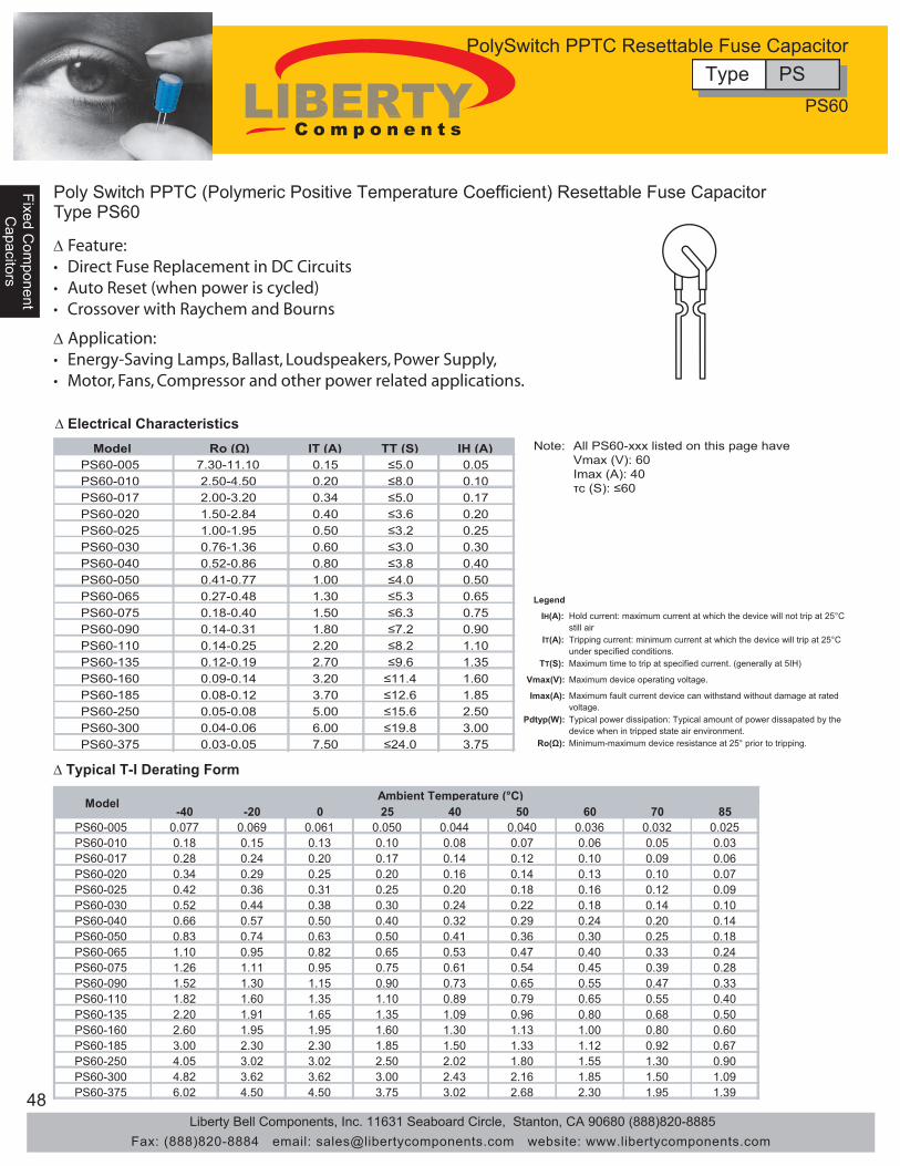
48
Fixed Com
ponentFixed C
omponent
Capacitors
Capacitors
Fixe
d C
ompo
nent
Cap
acito
rs
∆ Electrical Characteristics
-40 -20 0 25 40 50 60 70 85 PS60-005 0.077 0.069 0.061 0.050 0.044 0.040 0.036 0.032 0.025 PS60-010 0.18 0.15 0.13 0.10 0.08 0.07 0.06 0.05 0.03 PS60-017 0.28 0.24 0.20 0.17 0.14 0.12 0.10 0.09 0.06 PS60-020 0.34 0.29 0.25 0.20 0.16 0.14 0.13 0.10 0.07 PS60-025 0.42 0.36 0.31 0.25 0.20 0.18 0.16 0.12 0.09 PS60-030 0.52 0.44 0.38 0.30 0.24 0.22 0.18 0.14 0.10 PS60-040 0.66 0.57 0.50 0.40 0.32 0.29 0.24 0.20 0.14 PS60-050 0.83 0.74 0.63 0.50 0.41 0.36 0.30 0.25 0.18 PS60-065 1.10 0.95 0.82 0.65 0.53 0.47 0.40 0.33 0.24 PS60-075 1.26 1.11 0.95 0.75 0.61 0.54 0.45 0.39 0.28 PS60-090 1.52 1.30 1.15 0.90 0.73 0.65 0.55 0.47 0.33 PS60-110 1.82 1.60 1.35 1.10 0.89 0.79 0.65 0.55 0.40 PS60-135 2.20 1.91 1.65 1.35 1.09 0.96 0.80 0.68 0.50 PS60-160 2.60 1.95 1.95 1.60 1.30 1.13 1.00 0.80 0.60 PS60-185 3.00 2.30 2.30 1.85 1.50 1.33 1.12 0.92 0.67 PS60-250 4.05 3.02 3.02 2.50 2.02 1.80 1.55 1.30 0.90 PS60-300 4.82 3.62 3.62 3.00 2.43 2.16 1.85 1.50 1.09 PS60-375 6.02 4.50 4.50 3.75 3.02 2.68 2.30 1.95 1.39
Model Ambient Temperature (°C)
∆ Typical T-I Derating Form
∆ Application:• Energy-Saving Lamps, Ballast, Loudspeakers, Power Supply,• Motor, Fans, Compressor and other power related applications.
∆ Feature:• Direct Fuse Replacement in DC Circuits• Auto Reset (when power is cycled)• Crossover with Raychem and Bourns
Model Ro (Ω) IT (A) TT (S) IH (A) PS60-005 7.30-11.10 0.15 ≤5.0 0.05 PS60-010 2.50-4.50 0.20 ≤8.0 0.10 PS60-017 2.00-3.20 0.34 ≤5.0 0.17 PS60-020 1.50-2.84 0.40 ≤3.6 0.20 PS60-025 1.00-1.95 0.50 ≤3.2 0.25 PS60-030 0.76-1.36 0.60 ≤3.0 0.30 PS60-040 0.52-0.86 0.80 ≤3.8 0.40 PS60-050 0.41-0.77 1.00 ≤4.0 0.50 PS60-065 0.27-0.48 1.30 ≤5.3 0.65 PS60-075 0.18-0.40 1.50 ≤6.3 0.75 PS60-090 0.14-0.31 1.80 ≤7.2 0.90 PS60-110 0.14-0.25 2.20 ≤8.2 1.10 PS60-135 0.12-0.19 2.70 ≤9.6 1.35 PS60-160 0.09-0.14 3.20 ≤11.4 1.60 PS60-185 0.08-0.12 3.70 ≤12.6 1.85 PS60-250 0.05-0.08 5.00 ≤15.6 2.50 PS60-300 0.04-0.06 6.00 ≤19.8 3.00 PS60-375 0.03-0.05 7.50 ≤24.0 3.75
Legend
IH(A): Hold current: maximum current at which the device will not trip at 25°C still air
IT(A): Tripping current: minimum current at which the device will trip at 25°C under specified conditions.
TT(S): Maximum time to trip at specified current. (generally at 5IH)
Vmax(V): Maximum device operating voltage.
Imax(A): Maximum fault current device can withstand without damage at rated voltage.
Pdtyp(W): Typical power dissipation: Typical amount of power dissapated by the device when in tripped state air environment.
Ro(Ω): Minimum-maximum device resistance at 25° prior to tripping.
Note: All PS60-xxx listed on this page have Vmax (V): 60 Imax (A): 40 τc (S): ≤60
Poly Switch PPTC (Polymeric Positive Temperature Coefficient) Resettable Fuse Capacitor Type PS60
PS60
Type PSPolySwitch PPTC Resettable Fuse Capacitor
Liberty Bell Components, Inc. 11631 Seaboard Circle, Stanton, CA 90680 (888)820-8885Fax: (888)820-8884 email: [email protected] website: www.libertycomponents.com

49
Fixed Com
ponentC
apacitors
Fixe
d C
ompo
nent
Fixe
d C
ompo
nent
Cap
acito
rsC
apac
itors
∆ Dimensions
Model Amax (mm) Bmax (mm) Cmax (mm) Dtyp (mm) Diameter of Lead (mm)
Fig.
PS60-005 6.0 11.0 3.1 5.1 Φ0.6 1 PS60-010 6.0 11.0 3.1 5.1 Φ0.6 1 PS60-017 6.0 11.5 3.1 5.1 Φ0.6 1 PS60-020 6.0 11.5 3.1 5.1 Φ0.6 1 PS60-025 6.5 11.5 3.1 5.1 Φ0.6 1 PS60-030 8.0 13.5 3.1 5.1 Φ0.6 1 PS60-040 8.0 14.0 3.1 5.1 Φ0.6 1 PS60-050 8.0 14.0 3.1 5.1 Φ0.6 1 PS60-065 10.0 14.5 3.1 5.1 Φ0.6 1 PS60-075 11.0 15.5 3.1 5.1 Φ0.6 1 PS60-090 12.0 16.5 3.1 5.1 Φ0.6 1 PS60-110 13.0 17.0 3.1 5.1 Φ0.6 1 PS60-135 16.0 18.0 3.1 5.1 Φ0.6 2 PS60-160 17.0 20.0 3.1 5.1 Φ0.8 2 PS60-185 18.0 23.0 3.1 5.1 Φ0.8 2 PS60-250 21.5 23.5 3.1 10.2 Φ0.8 2 PS60-300 25.0 27.5 3.1 10.2 Φ0.8 2 PS60-375 28.5 32.5 3.1 10.2 Φ0.8 2
C A
B
D
C A
B
D
Fig. 1 Fig. 2
Poly Switch PPTC (Polymeric Positive Temperature Coefficient) Resettable Fuse Capacitor Type PS60
PS60
Type PSPolySwitch PPTC Resettable Fuse Capacitor
Liberty Bell Components, Inc. 11631 Seaboard Circle, Stanton, CA 90680 (888)820-8885Fax: (888)820-8884 email: [email protected] website: www.libertycomponents.com

50
Fixed Com
ponentFixed C
omponent
Capacitors
Capacitors
Fixe
d C
ompo
nent
Cap
acito
rs
F D
∆ Dimensions
Model IH (A) IT (A) Vmax (V) Imax (A) Ttrip (S) Pdtype (W) Ro (Ω) PS90-020 0.20 0.40 90 20 10 1.70 1.00-2.5 PS90-025 0.25 0.50 90 20 10 1.75 0.80-2.0 PS90-035 0.35 0.75 90 20 10 1.80 0.60-1.2 PS90-055 0.55 1.10 90 20 10 2.00 0.35-0.9 PS90-075 0.75 1.50 90 20 10 2.50 0.20-0.6 PS90-090 0.90 1.80 90 20 10 3.00 0.10-0.5
Model Amax Bmin Cmax Dtyp PS90-020 5.5 7.6 3.1 5.1 PS90-025 7.5 7.6 3.1 5.1 PS90-035 7.5 7.6 3.1 5.1 PS90-055 11.0 7.6 3.1 5.1 PS90-075 11.0 7.6 3.1 5.1 PS90-090 13.0 7.6 3.1 5.1
∆ Electrical Characteristics
∆ Typical T-I Derating Form
-40 -20 0 25 40 50 60 70 85 PS90-020 0.30 0.26 0.24 0.20 0.16 0.15 0.13 0.10 0.08 PS90-025 0.38 0.33 0.28 0.25 0.21 0.18 0.16 0.14 0.10 PS90-035 0.54 0.46 0.42 0.35 0.28 0.26 0.23 0.20 0.14 PS90-055 0.86 0.76 0.66 0.55 0.46 0.42 0.36 0.31 0.24 PS90-075 1.16 1.00 0.92 0.75 0.62 0.56 0.50 0.42 0.30 PS90-090 1.42 1.24 1.08 0.90 0.74 0.66 0.58 0.50 0.36
Ambient Temperature (°C) Model
0.01
0.1
1
10
100
1000
0.1 1 10 100
Fault Current (A)
Tim
e-to
-trip
(S)
A E C B
A=PS90-020 B=PS90-025 C=PS90-035 D=PS90-055 E=PS90-075 F=PS90-090
A
B
C
D
∆ Application:• Automotive Wiring Harness, Door Lock, Security Alarm,• Rain Brush, Actualtors and other Automotive applications.
∆ Feature:• Fuse Capacitor (use in place of traditional fuse)• Auto Reset (when power is cycled)
Poly Switch PPTC (Polymeric Positive Tempereature Coefficient) Resettable Fuse Capacitor Type PS90
Legend
IH(A): Hold current: maximum current at which the device will not trip at 25°C still air
IT(A): Tripping current: minimum current at which the device will trip at 25°C under specified conditions.
TT(S): Maximum time to trip at specified current. (generally at 5IH)
Vmax(V): Maximum device operating voltage.
Imax(A): Maximum fault current device can withstand without damage at rated voltage.
Pdtyp(W): Typical power dissipation: Typical amount of power dissapated by the device when in tripped state air environment.
Ro(Ω): Minimum-maximum device resistance at 25° prior to tripping.
PS90
Type PSPolySwitch PPTC Resettable Fuse Capacitor
Liberty Bell Components, Inc. 11631 Seaboard Circle, Stanton, CA 90680 (888)820-8885Fax: (888)820-8884 email: [email protected] website: www.libertycomponents.com

51
Fixed Com
ponentC
apacitors
Fixe
d C
ompo
nent
Fixe
d C
ompo
nent
Cap
acito
rsC
apac
itors
∆ Electrical Characteristics
I (A) (S) PS250-080F 60 14.00-22.00 0.16 1 ≤0.5 0.08 PS250-080N 60 14.00-22.00 0.16 1 ≤0.5 0.08 PS250-100F 60 12.00-18.00 0.2 1 ≤0.5 0.1 PS250-100N 60 12.00-18.00 0.2 1 ≤0.5 0.1 PS250-110F 60 6.00-12.00 0.22 1 ≤1.0 0.11 PS250-110N 60 6.00-12.00 0.22 1 ≤1.0 0.11 PS250-120F 60 4.00-12.00 0.24 1 ≤2.0 0.12 PS250-120N 60 6.00-12.00 0.24 1 ≤2.0 0.12 PS250-130F 60 4.00-10.00 0.26 1 ≤2.0 0.13
PS250-145F/U 60 3.00-8.00 0.29 1 ≤3.0 0.145 PS250-160F 60 2.00-6.00 0.32 3 ≤3.0 0.16 PS250-180U 60 0.80-2.00 0.6 3 ≤3.0 0.18 PS250-180F 60 0.80-2.00 0.6 3 ≤3.0 0.18 PS600-150N 60 6.00-12.00 0.3 3 ≤1.0 0.15 PS600-150F 60 6.00-12.00 0.3 3 ≤1.0 0.15 PS600-160F 60 4.00-10.00 0.32 3 ≤2.0 0.16
TT(S) IH (A) Model Vmax (V) Ro (Ω) IT (A)
∆ Application:• LAN Equipment, MDF Modules, Mobile Phones,• DSL Modems and other Telcom & Network Equipment.
∆ Feature:• Fuse Capacitor (use in place of traditional fuse)• Auto Reset (when power is cycled)
Poly Switch PPTC (Polymeric Positive Tempereature Coefficient) Resettable Fuse Capacitor Type PS250/600
Legend
IH(A): Hold current: maximum current at which the device will not trip at 25°C still air
IT(A): Tripping current: minimum current at which the device will trip at 25°C under specified conditions.
TT(S): Maximum time to trip at specified current. (generally at 5IH)
Vmax(V): Maximum device operating voltage.
Imax(A): Maximum fault current device can withstand without damage at rated voltage.
Pdtyp(W): Typical power dissipation: Typical amount of power dissapated by the device when in tripped state air environment.
Ro(Ω): Minimum-maximum device resistance at 25° prior to tripping.
PS250/600
Type PSPolySwitch PPTC Resettable Fuse Capacitor
Liberty Bell Components, Inc. 11631 Seaboard Circle, Stanton, CA 90680 (888)820-8885Fax: (888)820-8884 email: [email protected] website: www.libertycomponents.com

52
Fixed Com
ponentFixed C
omponent
Capacitors
Capacitors
Fixe
d C
ompo
nent
Cap
acito
rs
∆ Typical T-I Derating Form
A
B
C
D
A C
B
Fig 1. Fig 2.
0.01
0.1
1
10
100
1000
0.00 0.20 0.40 0.60 0.80 1.00 1.20 1.40 1.60 1.80 2.00 2.20 2.40 2.60 2.80 3.00
Fault Current (A)
Tim
e-to
-trip
(S)
PS250-180F/U
PS250-120F/NPS250-145F
PS250-110F/NPS250-080F/N
Model Amax (mm) Bmax (mm) Cmax (mm) Dtyp (mm)Diameter of Lead (mm)
Fig.
PS250-080F 7.0 10.0 4.6 5.1 Φ0.6 1PS250-080N 6.0 6.0 2.5 - - 2PS250-100F 7.0 10.0 4.6 5.1 Φ0.6 1PS250-100N 6.0 6.0 2.5 - - 2PS250-110F 7.0 10.0 4.6 5.1 Φ0.6 1PS250-110N 6.0 6.0 2.5 - - 2PS250-120F 7.0 10.0 4.6 5.1 Φ0.6 1PS250-120N 6.0 6.0 2.5 5.1 Φ0.6 2PS250-130F 7.5 11.0 4.6 5.1 Φ0.6 1
PS250-145F/U 7.5 11.0 4.6 5.1 Φ0.6 1PS250-160F 11.5 12.0 4.6 5.1 Φ0.6 1PS250-180U 11.0 12.0 4.6 5.1 Φ0.6 1PS250-180F 11.5 12.0 4.6 5.1 Φ0.6 1PS600-150N 13.5 12.0 6.5 5.1 Φ0.6 2PS600-150F 13.5 12.0 6.5 5.1 Φ0.6 1PS600-160F 13.5 16.0 6.5 5.1 Φ0.6 1
∆ Dimensions
Poly Switch PPTC (Polymeric Positive Temperature Coefficient) Resettable Fuse CapacitorType PS250/600
-40 -20 0 25 40 50 60 70 85PS250-080F/N 0.124 0.110 0.095 0.800 0.066 0.059 0.051 0.044 0.033PS250-100F/N 0.166 0.146 0.128 0.100 0.086 0.075 0.065 0.056 0.043PS250-110F/N 0.171 0.151 0.131 0.110 0.091 0.081 0.071 0.061 0.046PS250-120F/N 0.191 0.170 0.148 0.120 0.104 0.093 0.082 0.071 0.055PS250-130F 0.204 0.185 0.160 0.130 0.116 0.105 0.091 0.080 0.060
PS250-145F/U 0.225 0.199 0.172 0.145 0.119 0.106 0.093 0.080 0.060PS250-160F/U 0.250 0.220 0.195 0.160 0.137 0.123 0.110 0.095 0.074PS250-180F 0.269 0.240 0.211 0.180 0.153 0.138 0.123 0.109 0.087
PS600-150F/N 0.238 0.211 0.183 0.150 0.128 0.115 0.101 0.088 0.067PS600-160F 0.250 0.220 0.195 0.160 0.137 0.123 0.110 0.095 0.074
Ambient Temperature (°C)Model
PS250/600
Type PSPolySwitch PPTC Resettable Fuse Capacitor
Liberty Bell Components, Inc. 11631 Seaboard Circle, Stanton, CA 90680 (888)820-8885Fax: (888)820-8884 email: [email protected] website: www.libertycomponents.com
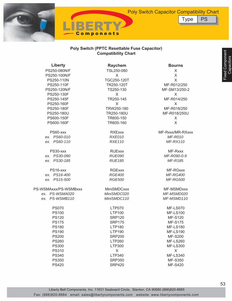
53
Fixed Com
ponentC
apacitors
Fixe
d C
ompo
nent
Fixe
d C
ompo
nent
Cap
acito
rsC
apac
itors
Liberty Raychem Bourns PS250-080N/F TSL250-080 X PS250-100N/F X X PS250-110N TGC250-120T X PS250-110F TR250-120T MF-R012/250
PS250-120N/F TS250-130 MF-SM13/250-2 PS250-130F X X PS250-145F TR250-145 MF-R014/250 PS250-160F X X PS250-180F TRW250-180 MF-R018/250 PS250-180U TR250-180U MF-R018/250U PS600-150F TR600-150 X PS600-160F TR600-160 X
PS60-xxx RXExxx MF-Rxxx/MR-RXxxx ex. PS60-010 RXE010 MF-R010 ex. PS60-110 RXE110 MF-RX110
PS30-xxx RUExxx MF-Rxxx ex. PS30-090 RUE090 MF-R090-0-9 ex. PS30-185 RUE185 MF-R185
PS16-xxx RGExxx MF-RGxxx ex. PS16-400 RGE400 MF-RG400 ex. PS15-500 RGE500 MF-RG500
PS-WSMAxxx/PS-WSMBxxx MiniSMDCxxx MF-MSMDxxx ex. PS-WSMA020 MiniSMDC020 MF-MSMD020 ex. PS-WSMB110 MiniSMDC110 MF-MSMD110
PS070 LTP070 MF-LS070 PS100 LTP100 MF-LS100 PS120 SRP120 MF-S120 PS175 SRP175 MF-S175 PS180 LTP180 MF-LS180 PS190 LTP190 MF-LS190 PS200 SRP200 MF-S200 PS260 LTP260 MF-LS260 PS300 LTP300 MF-LS300 PS310 X X PS340 LTP340 MF-LS340 PS350 SRP350 MF-S350 PS420 SRP420 MF-S420
Poly Switch (PPTC Resettable Fuse Capacitor) Compatibility Chart
Type PSPoly Switch Capacitor Compatibility Chart
Liberty Bell Components, Inc. 11631 Seaboard Circle, Stanton, CA 90680 (888)820-8885Fax: (888)820-8884 email: [email protected] website: www.libertycomponents.com

54
Fixed Com
ponentFixed C
omponent
Capacitors
Capacitors
Fixe
d C
ompo
nent
Cap
acito
rs
Polyester Film Capacitor Type PEI Series
• Inductive construction• High insulation resistance, moisture & wide temperature range
• Suitable for general use in various medical, telecom and industrial equipment
1.5Max
W Max
H Max
20Min
T Max
Φ d ± 0.1
Type A Type B
6.0Max
5.0 ± 0.5
F±1 F±1
6.0Max
5.0 ± 0.5
∆ Dimensions
Item CharacteristicsOperating Temperature Range - 40 ~ +85°CCapacitance Range 0.001μF ~ 0.47μFCapacitance Tolerance ± 2%(G), ± 5%(J), ± 10%(K)Standard Working Voltage DC50V(1H), 100V(2A), 250V(2E), 400V(2G), 630V(2J)Dissipation Factor Max 0.8% at 1kHz, 20°C
Min 30,000MΩ (C ≤ 0.33μF)Min 10,000MΩ (C > 0.33μF)
Withstanding Voltage Rated voltage X 2.5 (5sec)
Insulation Resistance
∆ Features
∆ Applications
∆ Specifications
Type PEIPolyester Film Capacitor
Liberty Bell Components, Inc. 11631 Seaboard Circle, Stanton, CA 90680 (888)820-8885Fax: (888)820-8884 email: [email protected] website: www.libertycomponents.com
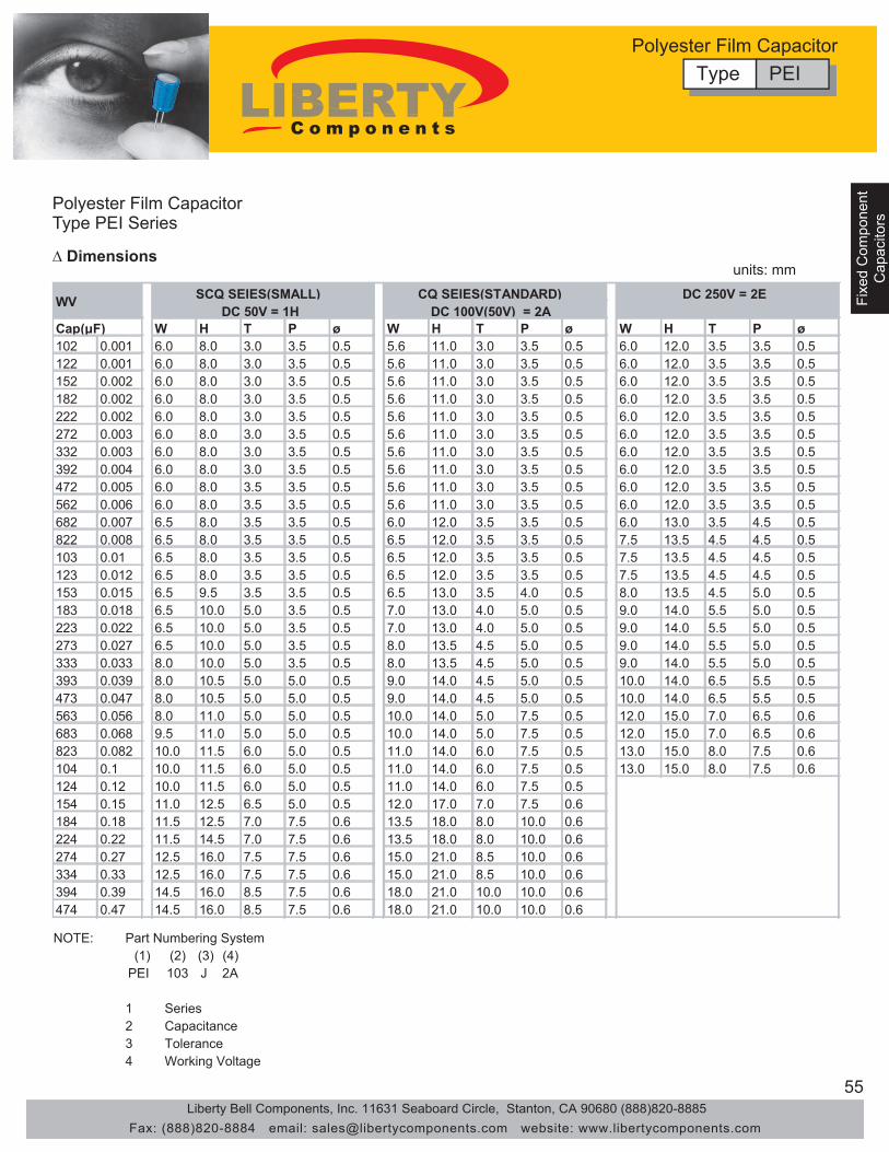
55
Fixed Com
ponentC
apacitors
Fixe
d C
ompo
nent
Fixe
d C
ompo
nent
Cap
acito
rsC
apac
itors
Polyester Film Capacitor Type PEI Series
W H T P ø W H T P ø W H T P ø102 0.001 6.0 8.0 3.0 3.5 0.5 5.6 11.0 3.0 3.5 0.5 6.0 12.0 3.5 3.5 0.5122 0.001 6.0 8.0 3.0 3.5 0.5 5.6 11.0 3.0 3.5 0.5 6.0 12.0 3.5 3.5 0.5152 0.002 6.0 8.0 3.0 3.5 0.5 5.6 11.0 3.0 3.5 0.5 6.0 12.0 3.5 3.5 0.5182 0.002 6.0 8.0 3.0 3.5 0.5 5.6 11.0 3.0 3.5 0.5 6.0 12.0 3.5 3.5 0.5222 0.002 6.0 8.0 3.0 3.5 0.5 5.6 11.0 3.0 3.5 0.5 6.0 12.0 3.5 3.5 0.5272 0.003 6.0 8.0 3.0 3.5 0.5 5.6 11.0 3.0 3.5 0.5 6.0 12.0 3.5 3.5 0.5332 0.003 6.0 8.0 3.0 3.5 0.5 5.6 11.0 3.0 3.5 0.5 6.0 12.0 3.5 3.5 0.5392 0.004 6.0 8.0 3.0 3.5 0.5 5.6 11.0 3.0 3.5 0.5 6.0 12.0 3.5 3.5 0.5472 0.005 6.0 8.0 3.5 3.5 0.5 5.6 11.0 3.0 3.5 0.5 6.0 12.0 3.5 3.5 0.5562 0.006 6.0 8.0 3.5 3.5 0.5 5.6 11.0 3.0 3.5 0.5 6.0 12.0 3.5 3.5 0.5682 0.007 6.5 8.0 3.5 3.5 0.5 6.0 12.0 3.5 3.5 0.5 6.0 13.0 3.5 4.5 0.5822 0.008 6.5 8.0 3.5 3.5 0.5 6.5 12.0 3.5 3.5 0.5 7.5 13.5 4.5 4.5 0.5103 0.01 6.5 8.0 3.5 3.5 0.5 6.5 12.0 3.5 3.5 0.5 7.5 13.5 4.5 4.5 0.5123 0.012 6.5 8.0 3.5 3.5 0.5 6.5 12.0 3.5 3.5 0.5 7.5 13.5 4.5 4.5 0.5153 0.015 6.5 9.5 3.5 3.5 0.5 6.5 13.0 3.5 4.0 0.5 8.0 13.5 4.5 5.0 0.5183 0.018 6.5 10.0 5.0 3.5 0.5 7.0 13.0 4.0 5.0 0.5 9.0 14.0 5.5 5.0 0.5223 0.022 6.5 10.0 5.0 3.5 0.5 7.0 13.0 4.0 5.0 0.5 9.0 14.0 5.5 5.0 0.5273 0.027 6.5 10.0 5.0 3.5 0.5 8.0 13.5 4.5 5.0 0.5 9.0 14.0 5.5 5.0 0.5333 0.033 8.0 10.0 5.0 3.5 0.5 8.0 13.5 4.5 5.0 0.5 9.0 14.0 5.5 5.0 0.5393 0.039 8.0 10.5 5.0 5.0 0.5 9.0 14.0 4.5 5.0 0.5 10.0 14.0 6.5 5.5 0.5473 0.047 8.0 10.5 5.0 5.0 0.5 9.0 14.0 4.5 5.0 0.5 10.0 14.0 6.5 5.5 0.5563 0.056 8.0 11.0 5.0 5.0 0.5 10.0 14.0 5.0 7.5 0.5 12.0 15.0 7.0 6.5 0.6683 0.068 9.5 11.0 5.0 5.0 0.5 10.0 14.0 5.0 7.5 0.5 12.0 15.0 7.0 6.5 0.6823 0.082 10.0 11.5 6.0 5.0 0.5 11.0 14.0 6.0 7.5 0.5 13.0 15.0 8.0 7.5 0.6104 0.1 10.0 11.5 6.0 5.0 0.5 11.0 14.0 6.0 7.5 0.5 13.0 15.0 8.0 7.5 0.6124 0.12 10.0 11.5 6.0 5.0 0.5 11.0 14.0 6.0 7.5 0.5154 0.15 11.0 12.5 6.5 5.0 0.5 12.0 17.0 7.0 7.5 0.6184 0.18 11.5 12.5 7.0 7.5 0.6 13.5 18.0 8.0 10.0 0.6224 0.22 11.5 14.5 7.0 7.5 0.6 13.5 18.0 8.0 10.0 0.6274 0.27 12.5 16.0 7.5 7.5 0.6 15.0 21.0 8.5 10.0 0.6334 0.33 12.5 16.0 7.5 7.5 0.6 15.0 21.0 8.5 10.0 0.6394 0.39 14.5 16.0 8.5 7.5 0.6 18.0 21.0 10.0 10.0 0.6474 0.47 14.5 16.0 8.5 7.5 0.6 18.0 21.0 10.0 10.0 0.6
DC 50V = 1HDC 250V = 2E
Cap(μF)
CQ SEIES(STANDARD)DC 100V(50V) = 2A
WV SCQ SEIES(SMALL)
∆ Dimensions
NOTE:(1) (2) (3) (4)
PEI 103 J 2A
1234
ToleranceWorking Voltage
Part Numbering System
SeriesCapacitance
Type PEIPolyester Film Capacitor
units: mm
Liberty Bell Components, Inc. 11631 Seaboard Circle, Stanton, CA 90680 (888)820-8885Fax: (888)820-8884 email: [email protected] website: www.libertycomponents.com
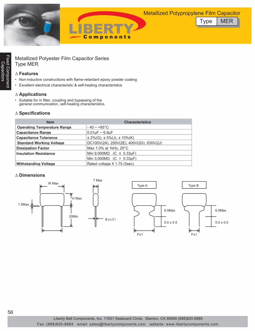
56
Fixed Com
ponentFixed C
omponent
Capacitors
Capacitors
Fixe
d C
ompo
nent
Cap
acito
rs
Metallized Polyester Film Capacitor SeriesType MER
• Non-inductive constructions with flame-retardant epoxy powder coating• Excellent electrical characteristic & self-healing characteristics
• Suitable for in filter, coupling and bypassing of the general communication, self-healing characteristics.
Item CharacteristicsOperating Temperature Range - 40 ~ +85°CCapacitance Range 0.01μF ~ 6.8μFCapacitance Tolerance ± 2%(G), ± 5%(J), ± 10%(K)Standard Working Voltage DC100V(2A), 250V(2E), 400V(2G). 630V(2J)Dissipation Factor Max 1.0% at 1kHz, 20°C
Min 9,000MΩ (C ≤ 0.33μF)Min 3,000MΩ (C > 0.33μF)
Withstanding Voltage Rated voltage X 1.75 (5sec)
Insulation Resistance
1.5Max
W Max
H Max
20Min
T Max
Φ d ± 0.1
Type A Type B
6.0Max
5.0 ± 0.5
F±1 F±1
6.0Max
5.0 ± 0.5
∆ Features
∆ Applications
∆ Specifications
∆ Dimensions
Type MERMetallized Polypropylene Film Capacitor
Liberty Bell Components, Inc. 11631 Seaboard Circle, Stanton, CA 90680 (888)820-8885Fax: (888)820-8884 email: [email protected] website: www.libertycomponents.com

57
Fixed Com
ponentC
apacitors
Fixe
d C
ompo
nent
Fixe
d C
ompo
nent
Cap
acito
rsC
apac
itors
W H T P ø W H T P ø W H T P ø103 0.01 14.0 10.5 6.0 11.5 0.7 14.0 10.5 6.5 11.5 0.7 14.0 10.5 6.5 11.5 0.7123 0.012 14.0 10.5 6.0 11.5 0.7 14.0 10.5 6.5 11.5 0.7 14.0 10.5 6.5 11.5 0.7153 0.015 14.0 10.5 6.0 11.5 0.7 14.0 10.5 6.5 11.5 0.7 14.0 10.5 6.5 11.5 0.7183 0.018 14.0 10.5 6.0 11.5 0.7 14.0 10.5 6.5 11.5 0.7 14.0 10.5 6.5 11.5 0.7223 0.022 14.0 10.5 6.0 11.5 0.7 14.0 10.5 6.5 11.5 0.7 14.0 10.5 6.5 11.5 0.7273 0.027 14.0 10.5 6.0 11.5 0.7 14.0 10.5 6.5 11.5 0.7 14.0 10.5 6.5 11.5 0.7333 0.033 14.0 10.5 6.0 11.5 0.7 14.0 10.5 6.5 11.5 0.7 14.0 10.5 6.5 11.5 0.7393 0.039 14.0 10.5 6.0 11.5 0.7 14.0 10.5 6.5 11.5 0.7 19.5 12.5 6.5 16.5 0.7473 0.047 14.0 10.5 6.0 11.5 0.7 14.0 10.5 6.5 11.5 0.7 19.5 12.5 6.5 16.5 0.7563 0.056 14.0 12.5 6.5 11.5 0.7 14.0 10.5 6.5 11.5 0.7 19.5 12.5 6.5 16.5 0.7683 0.068 14.0 12.5 6.5 11.5 0.7 14.0 10.5 6.5 11.5 0.7 19.5 12.5 6.5 16.5 0.7823 0.082 14.0 12.5 6.5 11.5 0.7 14.0 13.0 8.0 11.5 0.7 19.5 15.0 8.5 16.5 0.7104 0.1 14.0 12.5 6.5 11.5 0.7 16.5 13.0 6.5 15.0 0.7 19.5 15.0 8.5 16.5 0.7124 0.12 14.0 12.5 6.5 11.5 0.7 19.5 13.0 7.5 16.5 0.7 19.5 15.0 8.5 16.5 0.7154 0.15 14.0 12.5 6.5 11.5 0.7 19.5 13.0 7.5 16.5 0.7 25.0 16.0 9.5 21.5 0.7184 0.18 14.0 12.5 6.5 11.5 0.7 19.5 13.0 7.5 16.5 0.7 25.0 16.0 9.5 21.5 0.7224 0.22 19.5 12.5 6.5 16.5 0.7 25.0 14.5 7.5 21.5 0.7 25.0 18.0 9.5 21.5 0.8274 0.27 19.5 12.5 6.5 16.5 0.7 25.0 14.5 7.5 21.5 0.7 25.0 18.0 9.5 21.5 0.8334 0.33 19.5 12.5 6.5 16.5 0.7 25.0 17.0 9.0 21.5 0.7 25.0 19.5 10.5 26.5 0.8394 0.39 19.5 12.5 6.5 16.5 0.7 25.0 17.0 9.0 21.5 0.7 29.5 19.5 10.5 26.5 0.8474 0.47 19.5 13.5 6.5 16.5 0.7 25.0 17.0 11.0 21.5 0.8 29.5 22.0 12.0 26.5 0.8564 0.56 19.5 14.0 7.0 16.5 0.7 29.5 19.0 11.0 26.5 0.8 29.5 22.0 13.0 26.5 0.8684 0.68 25.0 14.0 7.0 21.5 0.7 29.5 19.0 11.0 26.5 0.8 30.0 25.0 15.0 26.5 0.8824 0.82 25.0 17.0 7.0 21.5 0.8 29.5 19.0 11.0 26.5 0.8 37.0 28.0 17.0 31.5 0.8105 1.0 25.0 17.0 9.5 21.5 0.8 30.0 21.5 13.5 26.5 0.8 37.0 28.0 17.0 31.5 0.8125 1.2 25.0 20.0 9.5 21.5 0.8 30.0 23.0 13.5 26.5 0.8 37.0 28.0 17.0 31.5 0.8155 1.5 29.5 20.0 9.5 26.5 0.8 30.0 24.0 15.0 26.5 0.8185 1.8 29.5 20.0 9.5 26.5 0.8205 2.0 29.5 20.0 9.5 26.5 0.8225 2.2 29.5 20.0 9.5 26.5 0.8275 2.7 30 20.0 11.0 26.5 0.8335 3.3 30 20.0 11.0 26.5 0.8475 4.7 30 25.0 14.0 26.5 0.8685 6.8 30 25.0 16.0 26.5 0.8
DC 400V = 2G DC 630V = 2JCap(μF)WV DC 250V (100V) = 2A
Metallized Polyester Film Capacitor SeriesType MER
∆ Dimensions
NOTE:(1) (2) (3) (4)
MER 103 M 2A
1234
ToleranceWorking Voltage
Part Numbering System
SeriesCapacitance
Type MERMetallized Polypropylene Film Capacitor
units: mm
Liberty Bell Components, Inc. 11631 Seaboard Circle, Stanton, CA 90680 (888)820-8885Fax: (888)820-8884 email: [email protected] website: www.libertycomponents.com

58
Fixed Com
ponentFixed C
omponent
Capacitors
Capacitors
Fixe
d C
ompo
nent
Cap
acito
rs
Metallized Polypropylene Film Capacitor Type MPR Series
• Non-inductive constructions• Low-loss & inherent temperature rise and excellent frequency characteristics
• Suitable for high frequency coupling and decoupling, sample and hold, and high fidelity circuitry
1.5Max
W Max
H Max
20Min
T Max
Φ d ± 0.1
Type A Type B
6.0Max
5.0 ± 0.5
F±1 F±1
6.0Max
5.0 ± 0.5
∆ Dimensions
Item CharacteristicsOperating Temperature Range - 40 ~ +85°CCapacitance Range 0.047μF ~ 1.0μFCapacitance Tolerance ± 5%(J), ± 10%(K)Standard Working Voltage DC100V(2A), 250V(2E), 400V(2G), 630V(2J)Dissipation Factor Max 1.0% at 1kHz, 20°C
Min 25,000MΩ (C ≤ 0.33μF)Min 7,000MΩ (C > 0.33μF)
Withstanding Voltage Rated voltage X 1.75 (5sec)
Insulation Resistance
∆ Features
∆ Applications
∆ Specifications
Type MPRMetallized Polypropylene Film Capacitor
Liberty Bell Components, Inc. 11631 Seaboard Circle, Stanton, CA 90680 (888)820-8885Fax: (888)820-8884 email: [email protected] website: www.libertycomponents.com

59
Fixed Com
ponentC
apacitors
Fixe
d C
ompo
nent
Fixe
d C
ompo
nent
Cap
acito
rsC
apac
itors
Metallized Polypropylene Film CapacitorType MPR Series
W H T P ø W H T P ø W H T P ø473 0.047 16.0 11.0 7.0 11.5 0.7 16.0 11.0 7.0 11.5 0.7 20.0 13.0 8.0 16.5 0.7563 0.056 16.0 11.0 7.0 11.5 0.7 16.0 11.0 7.0 11.5 0.7 20.0 13.0 8.0 16.5 0.7683 0.068 16.0 11.0 7.0 11.5 0.7 20.0 15.0 10.0 16.5 0.7 20.0 14.5 9.0 16.5 0.7823 0.082 16.0 11.0 7.0 11.5 0.7 20.0 15.0 10.0 16.5 0.7 20.0 14.5 9.0 16.5 0.7104 0.1 16.0 11.0 8.0 11.5 0.7 20.0 15.0 10.0 16.5 0.7 20.0 14.5 9.0 16.5 0.7124 0.12 16.0 11.0 8.0 11.5 0.7 20.0 16.0 10.0 16.5 0.7 20.0 15.0 10.0 16.5 0.7154 0.15 20.0 14.0 9.0 16.5 0.7 20.0 16.0 10.0 16.5 0.7 25.0 16.0 10.0 21.5 0.8184 0.18 20.0 14.0 9.0 16.5 0.7 20.0 16.0 10.0 16.5 0.7 25.0 16.0 10.0 21.5 0.8224 0.22 20.0 14.0 9.0 16.5 0.7 25.0 16.0 10.0 21.5 0.7 30.0 20.0 12.0 26.5 0.8274 0.27 20.0 14.0 9.0 16.5 0.7 25.0 16.0 10.0 21.5 0.7 30.0 20.0 12.0 26.5 0.8334 0.33 25.0 15.5 9.5 21.5 0.7 25.0 17.0 11.5 21.5 0.7 30.0 20.0 12.0 26.5 0.8394 0.39 25.0 15.5 9.5 21.5 0.7 25.0 17.0 11.5 21.5 0.7 30.0 20.0 12.0 26.5 0.8474 0.47 25.0 15.5 9.5 21.5 0.7 25.0 17.0 11.5 21.5 0.7 36.0 21.0 15.0 31.5 0.8564 0.56 25.0 18.0 12.0 21.5 0.8 25.0 18.5 12.5 21.5 0.7 36.0 21.0 15.0 31.5 0.8684 0.68 25.0 18.0 12.0 21.5 0.8 29.5 18.5 10.5 26.5 0.8 36.0 21.0 15.0 31.5 0.8824 0.82 25.0 18.0 12.0 21.5 0.8 29.5 18.5 10.5 26.5 0.8 36.0 24.0 18.0 31.5 0.8105 1.0 25.0 20.0 14.0 21.5 0.8 29.5 20.0 13.0 26.5 0.8 36.0 26.0 20.0 31.5 0.8125 1.2 25.0 20.0 14.0 21.5 0.8 29.5 20.0 13.0 26.5 0.8 36.0 26.0 20.0 31.5 0.8
DC 400V = 2G DC 630V = 2JCap(μF)WV DC 250V (100V) = 2A
∆ Features
NOTE: (1) (2) (3) (4)
MPR 103 J 2A
1234
ToleranceWorking Voltage
Part Numbering System
SeriesCapacitance
Type MPRMetallized Polypropylene Film Capacitor
units: mm
Liberty Bell Components, Inc. 11631 Seaboard Circle, Stanton, CA 90680 (888)820-8885Fax: (888)820-8884 email: [email protected] website: www.libertycomponents.com

60
Fixed Com
ponentFixed C
omponent
Resistors
Resistors
Fixe
d C
ompo
nent
Res
isto
rs
Zero Ohm and Jumper Wire Type RCF Series
• Used when circuit path on a PC board needs to be crossed over. • Used for circuit tuning by changing point connections.
H L D
d
RCF25 - OR - M / RCF12 - OR - M
L
dRCF25 - OR - W
Construction Part Number L D H (Min) d Jumper Wire RCF24 * - OR - W 61.5 ± 1 0.6 ± 0.5 Ceramic (Metal Body) RCF16 * - OR - C(M) 3.8 ± 0.5 1.5 ± 0.2 27 0.45 ± 0.5 Ceramic (Metal Body) RCF25 * - OR - C(M) 6.5 ± 0.3 2.5 ± 0.2 27 0.6 ± 0.5 Ceramic (Metal Body) RCF - 51 - OR - C(M) 9 ± 0.5 3.2 25 0.6 ± 0.5 Ceramic (Metal Body) RCF - 100 - OR - C(M) 11 4.5 30 0.8 ± 0.03 Ceramic (Metal Body) RCF - 200 - OR - C(M) 16 6 30 0.8 ± 0.03
∆ Specifications
∆ Applications
All Liberty Resistors uses the highest quality tin coatedcopper leads. The leads are rated at the belowMAXIMUM soldering temperature and soldering time.
MAXIMUM soldering temperature/time350°C 3sec235°C 2min
Type RCFZero Ohm and Jumper Wire
Test Test Method LimitsResistance 0.01 ohm max.Operating Temperature -55 ºC to +155 ºCMax Current 25amps @ +25 ºC (ZR25)Max Working Voltage 300VdcMax Overload Voltage 600VdcTemperature Coefficient (PPM/ ºC) 0 to -100 PPMShort Time Overload Apply 2.5 times the rated voltage for 5 sec. No visible damage
Load 1000 hrs. at 70 ºC a direct voltage applied, cycles of 1.5 hrs on and 0.5 hrs off throughout test. Δ R = 0.5%
Temperature Cycling5 cycles of 30 min. duration at the extrements of temp. range, max. and min., measurements of ohmic value 4 hrs. after completion of test.
Δ R = 0.5%
Dielectric Strength Using a 90 ºC "V" shaped conductive block, applying 100V min., increasing 100V/sec. for 5 seconds Δ R = 0.5%
Humidity 350 hrs. at 40 ºC, 90 to 95% Rh R = 0.5%Solderability Dipped in Sn/Pb(60/40) at 235 ºC, 5 sec. 1.5 mm from the body. 95% ø of tested surface coveredVibration By MIL STD.202, 201A
Terminal StrengthTraction, applied 2.5kg for 10 sec. Bends, 2 bends 90 ºC applying load to terminals of 0.5kg. Twist 2 successive turn 180 ºC, 6mm from body.
No visible damage
Resistance to Solvents Trichlorethylene, TMC as the most aggressive for 60 sec. at boiling point. No visible damage
Liberty Bell Components, Inc. 11631 Seaboard Circle, Stanton, CA 90680 (888)820-8885Fax: (888)820-8884 email: [email protected] website: www.libertycomponents.com

61
Fixed Com
ponentR
esistors
Fixe
d C
ompo
nent
Fixe
d C
ompo
nent
Res
isto
rsR
esis
tors
Carbon Film Fixed Resistors Type RCF Series
• Resistance temperature coefficient is relatively high.
• Low price.
• Easily used for various medical, telecom and consumer electronic equipment.
• Quick dissipation of heat and low temperature rise.
• Selected superior quality materials to ensure stability and reliability. • Variety of packaging available: bulk, strip pack, tape and reel, etc.
Dimensions
H L øD
d
JIS C 5202 MIL-STD-202 Type - -
± 150 -150 -700
-150 -1,000
-150 -1,300
0.125W Under 1K Ω
1.1K Ω - 47K Ω
51K Ω - 510K Ω
560 Ω - 1M Ω
0.25W Under 1K Ω
1.1K Ω - 150K Ω
160K Ω - 2.2M Ω
2.4M Ω - 5.1M Ω
0.5W & Over
Under 1K Ω
24K Ω - 470K Ω
510K Ω - 2.2K Ω
2.4M Ω - 10M Ω
Type 0.1 0.3 0.6 1.0
0.125W - Under 10K Ω
11K Ω - 100K Ω
Over 110K Ω
0.25W & Over
Under 100K Ω
110K Ω - 510K Ω
560K Ω - 2.2M Ω
Over 110K Ω
5.7-A Method 301 - Method 215
5.5-A 6.4, 350°C
3 Sec. Method 210
7.4, 55°C / 85°C Method 107
6.3.3-A Method 204 R>100KΩ R≤100KΩ R>100KΩ R≤100KΩ
Temperature Cycling
Vibration
Requirements Operating Temp. Range
Temp Coefficient (ppm/°C)
Noise (μV/V)
7.9,40°C 90-95% RH 1000Hrs
7.10, 70°C 1000Hrs
Method 106
Method 108
5.2 Method 304
5.9-11 Method 308
Moisture Resistance
Load Life
∆Rmax ≤ ± (1% ± 0.05Ω)
∆Rmax ≤ ± (0.5% ± 0.05Ω)
∆Rmax ≤ ± (0.5% ± 0.05Ω) ∆Rmax ≤ ± 5% ∆Rmax ≤ ± (3% ± 0.05Ω) ∆Rmax ≤ ± 3% ∆Rmax ≤ ± (2% ± 0.05Ω)
Resistance to Soldering Heat
Noise
∆Rmax ≤ ± (1% ± 0.05Ω) Permanent marking no physical or electrical damage or No evidence of flashover or breakdownDielectric Withstanding
Resistance to Solvents Short Time Overload
Performance -55°C ~ +155°C
Test Method
T.C.R.
∆ Features
∆ Applications
∆ Specifications
Type RCFCarbon Film Fixed Resistors
All Liberty Resistors uses the highest quality tin coatedcopper leads. The leads are rated at the belowMAXIMUM soldering temperature and soldering time.
MAXIMUM soldering temperature/time350°C 3sec235°C 2min
Liberty Bell Components, Inc. 11631 Seaboard Circle, Stanton, CA 90680 (888)820-8885Fax: (888)820-8884 email: [email protected] website: www.libertycomponents.com

62
Fixed Com
ponentFixed C
omponent
Resistors
Resistors
Fixe
d C
ompo
nent
Res
isto
rs
Carbon Film Fixed Resistors Type RCF Series
Temperature Coefficient
-1000
-800
-600
-400
-200
0
0 100 1K 10K 100K 1M
Ambient Temp °C
TC o
f R(P
PM /
°C)
Surface Temp Rise
20
40
60
80
0 25 50 75
Load (%)
Surf
ace
Tem
p (°
C)
Derating Curve
0
20
40
60
80
100
0 40 80 120 160
Ambient Temp (°C)
Load
(%
)
Current Noise
.003
.010
.032
.10
0
1.0
3.2
1K 10K 100K 1M
Nominal Resistance (Ω)
Noi
se V
olta
ge (μ
V/V)
CR300S
CR200S
CR100S
CR50S
CR33S
CR25S
CR16S
100
∆ Dimensions
∆ Part Numbering
52=1/2WS
105=1000000Ω
J = ± 5%
25=1/4W20=1/4WS
1D0=1.0Ω 100=10Ω
J
Series Power Rating Packaging Resistance Code Tolerance:
RCF 25 TR 100
Code TR=Tape Reel D50=0.50Ω
104=100000Ω
16=1/8W
101=100Ω 102=1000Ω 103=10000Ω
51=1/2W
200=2W100=1W
Type RCFCarbon Film Fixed Resistors
POWER L±0.5 D±0.5 H (Min) D±0.03 Max. Max.RATING (W) Working V. Overload V. ±2 %(G) ±5%(J)
RCF-16 1/8W 3.7 1.6 27 0.46 200V 400V 10Ω - 470K 0.1Ω - 47MRCF-20 1/4WS 3.7 1.6 27 0.46 200V 400V 10Ω - 470K 0.1Ω - 47MRCF-25 1/4W 6.5 2.5 27 0.58 250V 500V 10Ω - 1M 0.1Ω - 47MRCF-33 1/3W 8.5 2.8 25 0.58 300V 600V 10Ω - 1M 0.1Ω - 47MRCF-52 1/2WS 6.5 2.5 27 0.58 250V 500V 10Ω - 1M 0.1Ω - 47MRCF-50 1/2W 9.0 3.2 25 0.58 350V 700V 10Ω - 1M 0.1Ω - 47M
RCF-100 1W 11.0 4.5 30 0.80 500V 1000V 10Ω - 1M 0.1Ω - 47MRCF-200 2W 16.0 5.0 30 0.80 500V 1000V 10Ω - 1M 0.1Ω - 47MRCF-300 3W 17.0 6.0 30 0.80 650V 1200V 10Ω - 470K 0.1Ω - 47M
Resistance RangeType (mm)
Liberty Bell Components, Inc. 11631 Seaboard Circle, Stanton, CA 90680 (888)820-8885Fax: (888)820-8884 email: [email protected] website: www.libertycomponents.com

63
Fixed Com
ponentR
esistors
Fixe
d C
ompo
nent
Fixe
d C
ompo
nent
Res
isto
rsR
esis
tors
Carbon Flameproof Resistors Type RFP Series
• Complete nonflamable insulated coating
• Ensures safety • Does not burn in outside flaming or inside overloading
Dimensions
H L øD
d
Requirements Characteristics Test Method Non-Combustibility Flame Resistance: Will not burn continuously for more than 5 seconds. MIL-STD-202 Method 111
Overload Burning: will not fume under the overload of less than JIS C 5202 7. 12 5 times of rated power. The volume of fumes emitted under the overload EIAJ-RC 2658 5. 1 of more than 5 times of rated power is less than that of stilled fumes emitted by one cigarette. During the test the height of fumes does not go over 3 mm and the burning does not continue for more than 3 seconds.
∆ Features
∆ Specifications
∆ Characteristics
200=2W
105=1000000Ω
J = ± 5%
51=1/2W 25=1/4W
1D0=1.0Ω 100=10Ω
J
Series Power Rating Packaging Resistance Code Tolerance:
RFP 25 TR 100
Code 12=1/8W TR=Tape Reel D50=0.50Ω
104=100000Ω
16=1/6W
101=100Ω 102=1000Ω 103=10000Ω
100=1W
∆ Part Numbering
Type RFPCarbon Flameproof Resistors
All Liberty Resistors uses the highest quality tin coatedcopper leads. The leads are rated at the belowMAXIMUM soldering temperature and soldering time.
MAXIMUM soldering temperature/time350°C 3sec235°C 2min
Power Rating Max. Max.(W) L D d H (Min) Working V. Overload V. ±2 %(G) ±5%(J)
RFP 1/4 W (0.25 W) 6.5 ± 0.5 2.3 ± 0.2 0.58 ± 0.02 27 250 V 500 V 10Ω - 1M 1Ω - 10MRFP 1/2 W (0.5 W) 9 ± 1 3.5 ± 0.5 0.58 ±0.02 27 350 V 700 V 10Ω - 1M 1Ω - 10M
Resistance RangeDimensions (mm)Style
Liberty Bell Components, Inc. 11631 Seaboard Circle, Stanton, CA 90680 (888)820-8885Fax: (888)820-8884 email: [email protected] website: www.libertycomponents.com

64
Fixed Com
ponentFixed C
omponent
Resistors
Resistors
Fixe
d C
ompo
nent
Res
isto
rs
Metal Film Fixed ResistorsType RMF Series
• High aluminum content base material
• Excellent heat and wet proof special resin for protective coating
• Suitable for products for high reliability.
• Vacuum sputtered by Ni-Cr alloy
• Stable and uniform properties, excellent performance in open airDerating Curve
0
20
40
60
80
100
120
0 50 100 150 200 250
Ambient Temperature (C)
Perc
enta
ge o
f the
Rat
ed
Diss
ipat
ion
Dimensions
H L øD
d∆ Features
∆ Applications
∆ Resistance Range
∆ Dimensions (mm)
POWER TC±100PPM/ºCRATING (W) TC±50PPM/ºC
±1% 10Ω ~ 1MΩ 0.1Ω ~ 10MΩ±0.5% 100Ω ~ 1MΩ 1Ω ~ 10MΩ±0.25% 51.1Ω ~ 470KΩ 51.1Ω ~ 470KΩ±0.1% 51.1Ω ~ 470KΩ 51.1Ω ~ 470KΩ±1% 10Ω ~ 10MΩ 0.1Ω ~ 10MΩ±0.5% 0.1Ω ~ 10MΩ 0.1Ω ~ 10MΩ ±0.25% 10Ω ~ 470KΩ 10Ω ~ 470KΩ±0.1% 10Ω ~ 470KΩ 10Ω ~ 470KΩ±1% 0.1Ω ~ 10MΩ 0.1Ω ~ 10MΩ±0.5% 0.1Ω ~ 10MΩ 0.1Ω ~ 10MΩ ±0.25% 10Ω ~ 470KΩ 10Ω ~ 470KΩ±0.1% 10Ω ~ 470KΩ 10Ω ~ 470KΩ±1% 0.1Ω ~ 10MΩ 0.1Ω ~ 10MΩ±0.5% 0.1Ω ~ 10MΩ 0.1Ω ~ 10MΩ ±0.25% 1Ω ~ 1MΩ 10Ω ~ 470KΩ±0.1% 1Ω ~ 1MΩ 10Ω ~ 470KΩ±1% 0.1Ω ~ 10MΩ 0.1Ω ~ 10MΩ±0.5% 0.1Ω ~ 10MΩ 0.1Ω ~ 10MΩ ±0.25% 1Ω ~ 1MΩ 10Ω ~ 470KΩ±0.1% 1Ω ~ 1MΩ 10Ω ~ 470KΩ±1% 0.1Ω ~ 10MΩ 0.1Ω ~ 10MΩ±0.5% 0.1Ω ~ 10MΩ 0.1Ω ~ 10MΩ ±0.25% 1Ω ~ 1MΩ 1Ω ~ 470KΩ±0.1% 1Ω ~ 1MΩ 1Ω ~ 470KΩ
3 W
MF-16
1 W
MF-200 2 W
1/4 W
MF-50 1/2 W
STYLE TOLERANCE TC±25PPM/ºC
1/8 W
MF-25
MF-100
MF-300
Type Power L±0.5 D±0.5 H (Min) D±0.03 Max. Max.Rating (W) Working V. Overload V.
RMF-16 1/8W 3.7 1.8 27 0.46 200V 300VRMF-25 1/4W 6.5 2.5 27 0.58 250V 500VRMF-50 1/2W 9 3.7 25 0.68 400V 700VRMF-100 1W 11 4.5 33 0.8 500V 1000VRMF-200 2W 16 5 33 0.8 750V 1000VRMF-300 3W 17 6 30 0.8 750V 1000V
Type RMFMetal Film Fixed Resistors
• High-precision medical, telecom and consumer electronic equipment
Liberty Bell Components, Inc. 11631 Seaboard Circle, Stanton, CA 90680 (888)820-8885Fax: (888)820-8884 email: [email protected] website: www.libertycomponents.com
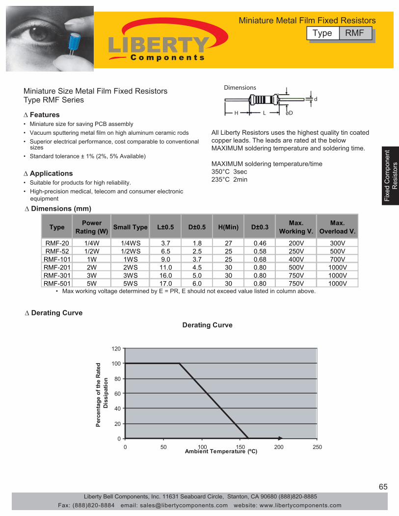
65
Fixed Com
ponentR
esistors
Fixe
d C
ompo
nent
Fixe
d C
ompo
nent
Res
isto
rsR
esis
tors
Miniature Size Metal Film Fixed Resistors Type RMF Series
• Miniature size for saving PCB assembly
• Superior electrical performance, cost comparable to conventional sizes
• Suitable for products for high reliability.
• Vacuum sputtering metal film on high aluminum ceramic rods
• Standard tolerance ± 1% (2%, 5% Available)
• Max working voltage determined by E = PR, E should not exceed value listed in column above.
Derating Curve
0
20
40
60
80
100
120
0 50 100 150 200 250Ambient Temperature (ºC)
Perc
enta
ge o
f the
Rat
ed
Diss
ipat
ion
Dimensions
H L øD
d
∆ Features
∆ Applications
∆ Derating Curve
∆ Dimensions (mm)
Type Power Rating (W) Small Type L±0.5 D±0.5 H(Min) D±0.3 Max.
Working V.Max.
Overload V.
RMF-20 1/4W 1/4WS 3.7 1.8 27 0.46 200V 300VRMF-52 1/2W 1/2WS 6.5 2.5 25 0.58 250V 500V
RMF-101 1W 1WS 9.0 3.7 25 0.68 400V 700VRMF-201 2W 2WS 11.0 4.5 30 0.80 500V 1000VRMF-301 3W 3WS 16.0 5.0 30 0.80 750V 1000VRMF-501 5W 5WS 17.0 6.0 30 0.80 750V 1000V
Type RMFMiniature Metal Film Fixed Resistors
All Liberty Resistors uses the highest quality tin coatedcopper leads. The leads are rated at the belowMAXIMUM soldering temperature and soldering time.
MAXIMUM soldering temperature/time350°C 3sec235°C 2min
• High-precision medical, telecom and consumer electronic equipment
Liberty Bell Components, Inc. 11631 Seaboard Circle, Stanton, CA 90680 (888)820-8885Fax: (888)820-8884 email: [email protected] website: www.libertycomponents.com
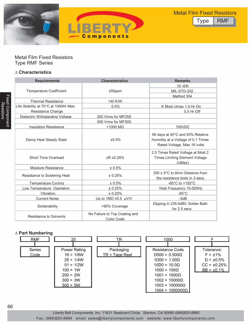
66
Fixed Com
ponentFixed C
omponent
Resistors
Resistors
Fixe
d C
ompo
nent
Res
isto
rs
Metal Film Fixed ResistorsType RMF Series
Requirements Characteristics Remarks 10 -6/K
MIL-STD-202 Method 304
Thermal Resistance 140 K/W 0.5% K Most Umax 1.5 Hr On
0.5 Hr Off Dielectric Withstanding Voltage 300 Vrms for MF25S
500 Vrms for MF50S Insulation Resistance >1000 MΩ 100VDC
Damp Heat Steady State ±0.5% 56 days at 40°C and 93% Relative Humidity at a Voltage of 0.1 Times
Rated Voltage, Max 16 volts
Short Time Overload ∆R ±0.25% 2.5 Times Rated Voltage at Most 2
Times Limiting Element Voltage (UMax)
Moisture Resistance ± 0.5%
Resistance to Soldering Heat ± 0.25% 350 ± 5°C to 6mm Distance from
the resistance body in 3 secs. Temperature Cycling ± 0.5% -65°C to +155°C
Low Temperature Operation ± 0.25% High Frequency 10-500Hz Vibration ± 0.25% -65°C
Current Noise Up to 1MΩ ≤0.5 μV/V -5dB
Solderability >95% Coverage Dipping in 235-5dBC Solder Bath
for 2.5 secs.
Resistance to Solvents No Failure to Top Coating and
Color Code
Life Stability at 70°C at 1000Hr Max Resistance Change
Temperature Coefficient ±50ppm
∆ Characteristics
∆ Part Numbering
16 = 1/8W D500 = 0.500Ω F = ±1%25 = 1/4W 1D00 = 1.00Ω D = ±0.5%51 = 1/2W 10D0 = 10.0Ω CC = ±0.25%
100 = 1W 1000 = 100Ω BB = ±0.1%200 = 2W 1001 = 1000Ω300 = 3W 1002 = 10000Ω500 = 5W 1003 = 100000Ω
1004 = 1000000Ω
TR = Tape ReelCodeSeries Power Rating Packaging Resistance Code Tolerance:
RMF 25 TR 1000 F
Type RMFMetal Film Fixed Resistors
Liberty Bell Components, Inc. 11631 Seaboard Circle, Stanton, CA 90680 (888)820-8885Fax: (888)820-8884 email: [email protected] website: www.libertycomponents.com

67
Fixed Com
ponentR
esistors
Fixe
d C
ompo
nent
Fixe
d C
ompo
nent
Res
isto
rsR
esis
tors
Miniature Metal Film Fixed ResistorsType RMF Series
Requirements Characteristics Remarks 10 -6/K
MIL-STD-202 Method 304
Thermal Resistance 140 K/W 0.5% K Most Umax 1.5 Hr On
0.5 Hr Off Dielectric Withstanding Voltage 300 Vrms for MF25S
500 Vrms for MF50S Insulation Resistance >1000 MΩ 100VDC
Damp Heat Steady State ±0.5% 56 days at 40°C and 93% Relative Humidity at a Voltage of 0.1 Times
Rated Voltage, Max 16 volts
Short Time Overload ∆R ±0.25% 2.5 Times Rated Voltage at Most 2
Times Limiting Element Voltage (UMax)
Moisture Resistance ± 0.5%
Resistance to Soldering Heat ± 0.25% 350 ± 5°C to 6mm Distance from
the resistance body in 3 secs. Temperature Cycling ± 0.5% -65°C to +155°C
Low Temperature Operation ± 0.25% High Frequency 10-500Hz Vibration ± 0.25% -65°C
Current Noise Up to 1MΩ ≤0.5 μV/V -5dB
Solderability >95% Coverage Dipping in 235-5dBC Solder Bath
for 2.5 secs.
Resistance to Solvents No Failure to Top Coating and
Color Code
Life Stability at 70°C at 1000Hr Max Resistance Change
Temperature Coefficient ±50ppm
∆ Characteristics
∆ Part Numbering
20 = 1/4WS D500 = 0.500Ω F = ±1%52 = 1/2WS 1D00 = 1.00Ω D = ±0.5%
101 = 1WS 10D0 = 10.0Ω CC = ±0.25%201 = 2WS 1000 = 100Ω BB = ±0.1%301 = 3WS 1001 = 1000Ω501 = 5WS 1002 = 10000Ω
1003 = 100000Ω1004 = 1000000Ω
TR = Tape ReelCodeSeries Power Rating Packaging Resistance Code Tolerance:
RMF 20 TR 1000 F
Type RMFMetal Film Fixed Resistors
Liberty Bell Components, Inc. 11631 Seaboard Circle, Stanton, CA 90680 (888)820-8885Fax: (888)820-8884 email: [email protected] website: www.libertycomponents.com

68
Fixed Com
ponentFixed C
omponent
Resistors
Resistors
Fixe
d C
ompo
nent
Res
isto
rs
Metal Flameproof Resistors Type RFM Series
• Nonflammable, high performance metal film fixed resistors
• Excellent electronic performance
• Suitable for products for high reliability.
• Flame-overload burning-resisting resin
70ºC 125 ºC L D H (min) d 70 ºC 125 ºC 70 ºC 125 ºCRFM 25 0.25W 0.1W 6.5±0.5 2.3±0.2 27 0.58±0.2 250 200 500 400RFM 50 0.5W 0.125W 9.0±1 3.5±0.5 27 0.65±0.2 350 250 700 500
Dimensions (mm)Style
Max Working Voltage Max Overload VoltagePower Rating (W)
Dimensions
H L øD
d
Requirements Characteristics Test MethodNon-Combustibility Flame Resistance: Will not burn continuously for more than 5 seconds. MIL-STD-202 Method 111
Overload Burning: will not fume under the overload of less than JIS C 5202 7. 125 times of rated power. The volume of fumes emitted under the overload EIAJ-RC 2658 5. 1of more than 5 times of rated power is less than that of stilled fumes emitted by one cigarette.During the test the height of fumes does not go over 3 mm and the burning does not continue for more than 3 seconds.
∆ Features
∆ Applications
∆ Characteristics
∆ Dimensions
500=5W
200=2W300=3W
1004=1000000Ω1003=100000Ω
F = ± 1%
51=1/2W25=1/4W
1D00=1.00Ω10D0=10.0Ω
16=1/6W
1000=100Ω
F
Series Power Rating Packaging Resistance Code Tolerance:
RFM 25 TR 1000
1001=1000Ω1002=10000Ω
100=1W
Code 12=1/8W TR=Tape Reel D500=0.500Ω
∆ Part Numbering
Type RFMMetal Flameproof Resistors
All Liberty Resistors uses the highest quality tin coatedcopper leads. The leads are rated at the belowMAXIMUM soldering temperature and soldering time.
MAXIMUM soldering temperature/time350°C 3sec235°C 2min• High-precision medical, telecom and consumer electronic
equipment
Liberty Bell Components, Inc. 11631 Seaboard Circle, Stanton, CA 90680 (888)820-8885Fax: (888)820-8884 email: [email protected] website: www.libertycomponents.com

69
Fixed Com
ponentR
esistors
Fixe
d C
ompo
nent
Fixe
d C
ompo
nent
Res
isto
rsR
esis
tors
Metal Flameproof Resistors Type RFM Series
0.003
0.010
0.032
0.10
0.32
1.0
100 110 120 130 140 150
Nominal Resistance (Ω)
μV/V
0
-10
-20
-30
-40
-50
dB
∆ Characteristics
∆ Current Noise
Type RFMMetal Flameproof Resistors
Characteristic Specification Test MethodAll resistance measurements should be performed after stabilication or consitioning periods.
DC Resistance Within Specified Tolerance MIL-STD-202 Method 303As Buyer Requested±25ppm/°C ±100ppm/°C±50ppm/°C ±200ppm/°C
MIL-STD-202 Method 3011/8W 300V 1 Minute, 1/4 500V 1 Minute1/8W 300V 1 Minute, 1/4 500V 1 MinuteMIL-STD-202 Method 302100V 1 Minute
Below 10KΩ Below 0.05μV/V10KΩ - Below 0.1μV/VBelow 1M7 Below 0.2μV/V
MIL-STD-202 Method 201 10HzX.Y.Z. 3 Directions 2 Hours each
Torminal Strength Lead does not break or loosen MIL-STD-202 Method 211MIL-STD-202 Method 210350°C, 3 ± 0.05Sec.MIL-STD-202 Method 208230°C, 0.05Sec.MIL-STD-202 Method 107-55°C +155°C5 CyclesMIL-R-10509 PARA, 4,6,6,2.5 Times Rated Working Voltage,5 Secs
∆R Within ± (1% 0.05Ω) MIL-STD-202 Method 103No Mechanical Damage 40°C, RH95% 500
MIL-R-10509 PARA, 4,6,5,Rated Working Voltage, at -65°C45 MinutesMIL-STD-202 Method 108 Rated WorkingVoltage 1 1/2 Hours on 1/2 Hours OffFor Total 1000Hours
Color Bands Legible NoMechanical Damage
Vibration
Resistance to Soldering Heat
Solderability
Thermal Shock
Temperature Coefficient
Dielectric Strength
Insulation Resistance
Current Noise Test
∆R Within ± (0.5% 0.05Ω)
∆R Within ± (0.5% 0.05Ω)
∆R Within ± (1% 0.05Ω)
Short Time Overload
Humidity
Low Temperature Operation
Load Life
MIL-STD-202 Method 304
MIL-STD-202 Method 308
MIL-STD-202 Method 215Resistance To Solvent
No Flashover or Damage
At Least 1,000MΩ
∆R Within ± (0.25% 0.05Ω)
∆R Within ± (0.25% 0.05Ω)
At Least 95% Coverage
∆R Within ± (0.5% 0.05Ω)
Liberty Bell Components, Inc. 11631 Seaboard Circle, Stanton, CA 90680 (888)820-8885Fax: (888)820-8884 email: [email protected] website: www.libertycomponents.com

70
Fixed Com
ponentFixed C
omponent
Resistors
Resistors
Fixe
d C
ompo
nent
Res
isto
rs
Metal Oxide Film Resistors Type RMO Series
• Special metal oxide film thermochemically burned on
• Electrical and mechanical stability and high reliability
• Easily used for various kinds of medical, telecom and electronic devices and instruments.
• High heat conductive base material
• Coating and marking resist trichlorethelyne freon and clearing agents • 1/2-3W apply color code
RSF4
Derating Curve
0
20
40
60
80
100
120
-100 -50 0 50 100 150 200 250 300
Ambient Temperature (ºC)
Load
(%)
Surface Temperature Rise
0
50
100
150
200
250
0 20 40 60 80 100 120
Load (%)
Surfa
ce T
empe
ratu
re (º
C) RSF5
RSF4 RSF3
RSF2
RSF1
RSF 1/2
Dimensions
H L øD
d
∆ Features
∆ Applications
∆ Specifications Max Working Max Overload Resistance
L D d H(MIN) Voltage Voltage Range ±5% (J) RMO-12 1/8W 3.7±0.4 1.8±0.2 0.46±0.02 27 200V 400V 0.1Ω-1M Ω RMO-25 1/4W 6.8±0.5 2.5±0.2 0.58±0.02 27 250V 500V 0.1Ω-1M Ω RMO-51 1/2W 9±1 3.0±0.5 0.68±0.02 25 300V 600V 0.1Ω-1M Ω RMO-100 1W 12±1 4.5±0.5 0.8±0.03 30 350V 700V 0.1Ω-1M Ω RMO-200 2W 16±1 5±0.5 0.8±0.03 30 350V 700V 0.1Ω-1M Ω RMO-300 3W 18±1 6±0.5 0.8±0.03 30 500V 1000V 0.1Ω-1M Ω RMO-500 5W 25±1 8.5±0.5 0.8±0.03 30 750V 1000V 0.1Ω-1M Ω
Max Working Max Overload Resistance L D d H(MIN) Voltage Voltage Range ±5% (J)
RMO-20 1/4WS 3.7±0.4 1.8±0.2 0.46±0.02 27 250V 500V 0.1Ω-1M Ω RMO-52 1/2WS 6.8±0.5 2.5±0.2 0.58±0.02 27 300V 600V 0.1Ω-1M Ω RMO-101 1WS 9±1 3.0±0.5 0.68±0.02 25 350V 700V 0.1Ω-1M Ω RMO-201 2WS 12±1 4.5±0.5 0.8±0.03 30 350V 700V 0.1Ω-1M Ω RMO-301 3WS 16±1 5±0.5 0.8±0.03 30 500V 1000V 0.1Ω-1M Ω RMO-501 5WS 18±1 6±0.5 0.8±0.03 30 750V 1200V 0.1Ω-1M Ω RMO-701 7WS 25±1 8.5±0.5 0.8±0.03 30 800V 1500V 0.1Ω-1M Ω
DIMENSION(mm) Part Type
Part Small Type DIMENSION(mm)
Type RMOMetal Oxide Film Resistors
All Liberty Resistors uses the highest quality tin coatedcopper leads. The leads are rated at the belowMAXIMUM soldering temperature and soldering time.
MAXIMUM soldering temperature/time350°C 3sec235°C 2min
Liberty Bell Components, Inc. 11631 Seaboard Circle, Stanton, CA 90680 (888)820-8885Fax: (888)820-8884 email: [email protected] website: www.libertycomponents.com
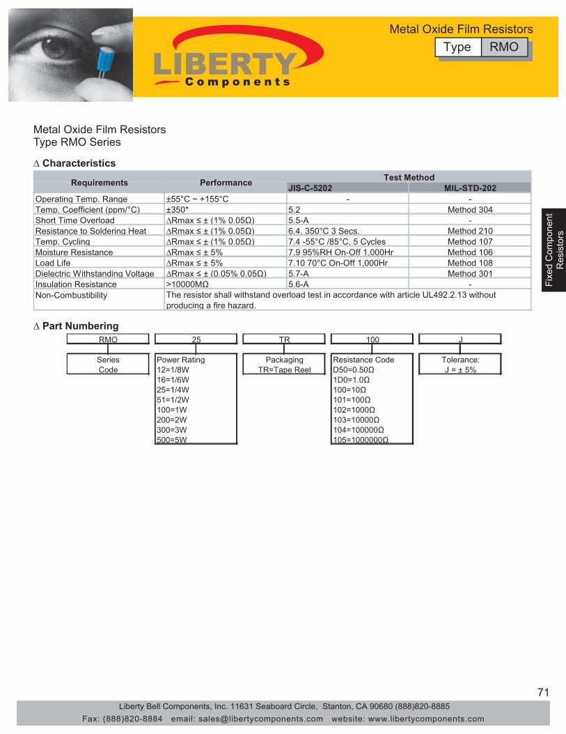
71
Fixed Com
ponentR
esistors
Fixe
d C
ompo
nent
Fixe
d C
ompo
nent
Res
isto
rsR
esis
tors
∆ Characteristics
JIS-C-5202 MIL-STD-202Operating Temp. Range ±55°C ~ +155°C - -Temp. Coefficient (ppm/°C) ±350* 5.2 Method 304Short Time Overload ∆Rmax ≤ ± (1% 0.05Ω) 5.5-A -Resistance to Soldering Heat ∆Rmax ≤ ± (1% 0.05Ω) 6.4. 350°C 3 Secs. Method 210Temp. Cycling ∆Rmax ≤ ± (1% 0.05Ω) 7.4 -55°C /85°C, 5 Cycles Method 107Moisture Resistance ∆Rmax ≤ ± 5% 7.9 95%RH On-Off 1,000Hr Method 106Load Life ∆Rmax ≤ ± 5% 7.10 70°C On-Off 1,000Hr Method 108Dielectric Withstanding Voltage ∆Rmax ≤ ± (0.05% 0.05Ω) 5.7-A Method 301Insulation Resistance >10000MΩ 5.6-A -Non-Combustibility The resistor shall withstand overload test in accordance with article UL492.2.13 without
producing a fire hazard.
Test MethodPerformanceRequirements
500=5W
200=2W300=3W
105=1000000Ω104=100000Ω
J = ± 5%
51=1/2W25=1/4W
1D0=1.0Ω100=10Ω
16=1/6W
101=100Ω
J
Series Power Rating Packaging Resistance Code Tolerance:
RMO 25 TR 100
102=1000Ω103=10000Ω
100=1W
Code 12=1/8W TR=Tape Reel D50=0.50Ω
∆ Part Numbering
Metal Oxide Film ResistorsType RMO Series
Type RMOMetal Oxide Film Resistors
Liberty Bell Components, Inc. 11631 Seaboard Circle, Stanton, CA 90680 (888)820-8885Fax: (888)820-8884 email: [email protected] website: www.libertycomponents.com
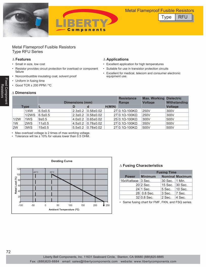
72
Fixed Com
ponentFixed C
omponent
Resistors
Resistors
Fixe
d C
ompo
nent
Res
isto
rs
Metal Flameproof Fusible Resistors Type RFU Series
• Small in size, low cost
• Noncombustible insulating coat, solvent proof
• Excellent application for high temperatures• Resistor provides circuit protection for overload or component failure
• Uniform in fusing time• Good TCR ± 200 PPM / ºC
• Suitable for use in transistor protection circuits
Resistance Max. Working DielectricRange Voltage Withstanding
L D d H(MIN) Voltage 1/4W 6.5±0.5 2.3±0.2 0.58±0.02 27 0.1Ω-100KΩ 250V 300V
1/2WS 6.5±0.5 2.3±0.2 0.58±0.02 27 0.1Ω-100KΩ 250V 300V 1/2W 1WS 9±0.5 4.0±0.2 0.65±0.02 25 0.1Ω-100KΩ 300V 500V 1W 2WS 11±0.5 4.5±0.2 0.78±0.02 27 0.1Ω-100KΩ 350V 500V 2W 3WS 15±0.5 5.5±0.2 0.78±0.02 27 0.1Ω-100KΩ 500V 500V
Dimensions (mm)Type
• Max overload voltage is 2 times of max working voltage.• Tolerance will be ± 10% for values lower than 0.5 OHM.
• Same fusing chart for FMF, FKN, and FSQ series.
Derating Curve
0
20
40
60
80
100
120
-100 -50 0 50 100 150 200 250
Ambient Temperature (ºC)
Rat
ed L
oad
(%) Minimum Nominal Maximum
16xWattage 3 Sec. 30 Sec. 1 Min.20 2 Sec. 15 Sec. 30 Sec.24 1 Sec. 5 Sec. 10 Sec.28 0.8 Sec. 3 Sec. 7 Sec.32 0.8 Sec. 2 Sec. 4 Sec.
Fusing TimePower
∆ Features ∆ Applications
∆ Fusing Characteristics
∆ Dimensions
-40°C 25°C
Type RFUMetal Flameproof Fusible Resistors
• Excellent for medical, telecom and consumer electronic equipment use.
Liberty Bell Components, Inc. 11631 Seaboard Circle, Stanton, CA 90680 (888)820-8885Fax: (888)820-8884 email: [email protected] website: www.libertycomponents.com
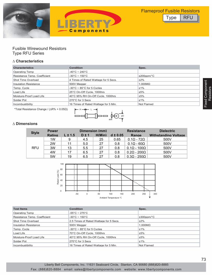
73
Fixed Com
ponentR
esistors
Fixe
d C
ompo
nent
Fixe
d C
ompo
nent
Res
isto
rsR
esis
tors
Fusible Wirewound Resistors Type RFU Series
Characteristics Condition Spec.Operating Temp -40°C ~ 240°CResistance Temp. Coefficient -30°C ~ 150°C ±200ppm/°CShot Time Overload 4 Times of Rated Wattage for 5 Secs. ±2%Insulation Resistance 500V Megger 1,000MΩTemp. Cycle -30°C ~ 85°C for 5 Cycles ±1%Load Life 25°C On-Off Cycle, 1000hrs ±5%Moisture-Proof Load Life 40°C 95% RH On-Off Cycle, 1000hrs ±5%Solder Pot 270°C for 3 Secs ±1%Incombustibility 16 Times of Rated Wattage for 5 Min. Not Flamed
H L
ød
øD
*Total Resistance Change / (∆R% + 0.05Ω)
0
20
40
60
80
100
-50 0 50 100 150 200 250 300
Ambient Temperature °C
Rat
ed L
oad
(%)
Test Items Condition Spec.Operating Temp -55°C ~ 275°CResistance Temp. Coefficient -30°C ~ 150°C ±300ppm/°CShot Time Overload 2.5 Times of Rated Wattage for 5 Secs. ±2%Insulation Resistance 500V Megger 1,000MΩTemp. Cycle -30°C ~ 85°C for 5 Cycles ±1%Load Life 70°C On-Off Cycle, 1000hrs ±5%Moisture-Proof Load Life 40°C 95% RH On-Off Cycle, 1000hrs ±5%Solder Pot 270°C for 3 Secs ±1%Incombustibility 16 Times of Rated Wattage for 5 Min. Not Flamed
∆ Characteristics
∆ Dimensions
Type RFUFlameproof Fusible Resistors
L ± 1.5 D ± 1 H(Min) d ± 0.051W 9 4.5 25 0.65 0.1Ω - 72Ω 500V2W 11 5.0 27 0.8 0.1Ω - 60Ω 500V3W 13 5.5 27 0.8 0.1Ω - 100Ω 500V4W 17 6.5 27 0.8 0.2Ω - 200Ω 500V5W 19 6.5 27 0.8 0.3Ω - 250Ω 500V
Resistance Range
Dielectric Withstanding Voltage
Dimension (mm)
RFU
Style PowerRating
Liberty Bell Components, Inc. 11631 Seaboard Circle, Stanton, CA 90680 (888)820-8885Fax: (888)820-8884 email: [email protected] website: www.libertycomponents.com

74
Fixed Com
ponentFixed C
omponent
Resistors
Resistors
Fixe
d C
ompo
nent
Res
isto
rs
General Specification of Resistors
∆ How to Apply Resistors Correctly
±2% ±5% ±1% ±0.5% ±2% ±5% ±1% ±0.5% E24 E48 E96 E192 E24 E48 E96 E192 100 100 100 100 330
101 332 332 332 102 102 336
104 340 340 105 105 105 344
106 348 348 348 107 107 352
109 357 357 110 110 110 110 360
111 361 113 113 365 365 365
114 370 115 115 115 374 374
117 379 118 118 383 383 383
120 120 388 121 121 121 390
123 392 392 124 124 397
126 402 402 402 127 127 127 407
129 412 412 130 130 130 417
132 422 422 422 133 133 133 427
135 430 137 137 432 432
138 437 140 140 140 442 442 442
142 448 143 143 453 453
145 459 147 147 147 464 464 464
149 470 470 150 150 150 475 475
152 481 154 154 154 487 487 487
156 493 158 158 499 499
160 160 505 162 162 162 510
164 511 511 511 165 165 517
167 523 523 169 169 169 530
172 536 536 536 174 174 542
176 549 549 178 178 178 556
180 180 560 182 182 562 562 562
184 569 187 187 187 576 576
189 583 191 191 590 590 590
193 597 196 196 196 604 604
198 612 200 200 200 619 619 619
203 620 205 205 205 626
208 634 634 210 210 642
213 649 649 649 215 215 215 657
218 665 665 220 673
221 221 680 223 681 681 681
226 226 226 690 229 698 698
232 232 706 234 715 715 715
237 237 237 723 240 732 732
243 243 741 246 750 750 750 750
249 249 249 759 252 768 768
255 255 777 258 787 787 787
261 261 261 796 264 806 806
267 267 816 270 820
271 825 825 825 274 274 274 835
277 845 845 280 280 856
284 866 866 866 287 287 287 876
291 887 887 294 294 898
298 909 909 909 300 910
301 301 301 920 305 931 931
309 309 942 312 953 953 953
316 316 316 965 320 976 976
324 324 988 328
Color 1st Band 2nd Band 3rd Band Multiplier Tolerance Black 0 0 0 100 Brown 1 1 1 101 F(±1%) Red 2 2 2 102 G(±2%) Orange 3 3 3 103 Yellow 4 4 4 104 Green 5 5 5 105 D(±0.5%) Blue 6 6 6 106 C(±0.25%) Violet 7 7 7 107 B(±0.1%) Gray 8 8 8 White 9 9 9 10-3 Gold 10-1 J(±5%) Silver 10-2 K(±10%) Plain M(±20%)
Symbol T E C K J L D
T.C.R. ±10 ±25 ±50 ±100 ±150 ±200 +200 -500
Symbol A B C D F G J K M Resistance Tolerance ±0.05 ±0.1 ±0.25 ±.05 ±1 ±2 ±5 ±10 ±20
·The characteristics of resistor have relations to temperature moisture and voltage. ·The rating of resistor is specified on the basis of temperautre.·The power rating of resistor is all specified with a direct-current. (D.C.) continuous working voltage or sine-wave root-mean-square (RMS) continuous working voltage at commercial-line frequency. · The tests regarding characteristics of resistor is principally specified on the basis of moisture. ·Maximum rated voltage and maximum overload voltage are limited for each style of resistor, (1) Generally, rated voltage E=√PR where E=volt, P=watt, R=ohm. (2) Generally, overload voltage ET=√PR x2.5, application time=5secs. NOTE: Max Rated and Max Overload Voltage are specified in each specification, so if the voltage valued computed, is over than specified voltage value, the specified value should be applied to resistor. ·In the complicated or high density circuit, it is recommended that the wattage or OHMIC values or resistor should have a large redundancy from a view point of reliability. ·It is necessary that the handliing or wiring of resistor to the circuit is careful and please do not apply any stress to the resisotr by over heating. ·To rise the reliability of resistor, it is better to prefer resistor with uniform quality than taking resistor met with severe specification. To rise the stability of resistor, it is very important to take resistor met with circuit conditions and is also economical not to have unreasonable design from apoint of pricing resistor. ·Generally, failure of resisor takes a concentrated trend in the impulse circuit with complicated pulse wave form or LC circuit generated high voltage with transient phenomena, therefore, it is very important for designers to consider these conditions in the circuit design, if the resistor is applied in these circuits.
E6, E12, E24 E24, E96
General Specification of Resistors
Liberty Bell Components, Inc. 11631 Seaboard Circle, Stanton, CA 90680 (888)820-8885Fax: (888)820-8884 email: [email protected] website: www.libertycomponents.com

75
Fixed Com
ponentR
esistors
Fixe
d C
ompo
nent
Fixe
d C
ompo
nent
Res
isto
rsR
esis
tors
• No self-ignition even if current overflows
• Instant overload capability; low noise, no annual shift on resistance • Superior heat dissipation; small linear temperature coefficient
Test Items Condition Spec. Operating Temp -55°C ~ 275°C Resistance Temp. Coefficient -30°C ~ 150°C ±300ppm/°C Shot Time Overload 2.5 Times of Rated Wattage for 5 Secs. ±2% Insulation Resistance 500V Megger 1,000MΩ Temp. Cycle -30°C ~ 85°C for 5 Cycles ±1% Load Life 70°C On-Off Cycle, 1000hrs ±5% Moisture-Proof Load Life 40°C 95% RH On-Off Cycle, 1000hrs ±5% Solder Pot 270°C for 3 Secs ±1% Incombustibility 16 Times of Rated Wattage for 5 Min. Not Flamed
Temperature Rise at 25°C
0
50
100
150
200
250
300
100 110 120 130 140 150 160
% of Rated Load
Tem
pera
ture
Ris
e (°
C)
Temperature Rise at 25°C
0
100
200
300
25 50 75 100 125
% of Rated Load
Tem
pera
ture
Ris
e (°
C)
(without Bracket) Derating Curve
0
20
40
60
80
100
-50 0 50 100 150 200 250 300
Ambient Temperature (°C)
Load
(%)
W-50E W-40
W-30
W-22-25
W-15-16
W-10 W-7
W-5
W-3
W-2
∆ Features
∆ Specifications
∆ Characteristics
∆ Part Numbering
102=1000Ω 103=10000Ω
10=10W
Code 02=2W J = ± 5% D50=0.50Ω Series Power Rating Tolerance: Resistance Code
RLA 05 J 100
07=7W 05=5W
1D0=1.0Ω 100=10Ω
03=3W
101=100Ω
15=15W 20=20W
105=1000000Ω 104=100000Ω
Wirewound Rectangular Resistor
Wirewound Rectangular Resistor
Liberty Bell Components, Inc. 11631 Seaboard Circle, Stanton, CA 90680 (888)820-8885Fax: (888)820-8884 email: [email protected] website: www.libertycomponents.com

76
Fixed Com
ponentFixed C
omponent
Resistors
Resistors
Fixe
d C
ompo
nent
Res
isto
rs
• Note: Non-inductive type up to 15.
W S
H
4 ± 1
5 ± 1 0.8 ± 0.05
H
W
MIN 27 L
t 0.8 ± 0.05
MIN 27 L W
H
MIN 27
d
RLA (SQP)
RLM (SQM)
RQT (SQT)
Max Working L ±.0.5 W ± 0.5 H ± 0.5 d ± 0.03 RLA RS+RLA Voltage
2W 18.0 7.0 7.0 0.65 0.1Ω ~ 120Ω 120~20KΩ 15V 3W 22.0 8.0 8.0 0.8 0.1Ω ~ 150Ω 150~33KΩ 350V 5W 22.0 9.5 9.0 0.8 0.1Ω ~ 200Ω 200~50KΩ 350V 7W 35.0 9.5 9.0 0.8 0.1Ω ~ 500Ω 500~50KΩ 500V 10W 48.0 9.5 9.0 0.8 0.1Ω ~ 1KΩ 1K~50KΩ 750V 15W 48.0 12.5 12.0 0.8 0.5Ω ~ 1KΩ 1K~150KΩ 1000V 20W 60.0 14.0 13.5 0.8 0.5Ω ~ 1KΩ 1K~150KΩ 1000V
Dimensions (mm) Resistance Range (Ω) RLA
TYPE RLM H ± 1.5 W ± 1 S ± 1 RLM RS + RLM 2W 20 11 1.7 0.1 - 20 Ω 20 - 47KΩ 3W 25 12 9 0.1 - 50 Ω 50 - 47KΩ 5W 25 13 9 0.1 - 100 Ω 100 - 47KΩ 7W 39 13 9 0.1 - 500 Ω 500 - 47KΩ 10W 51 13 9 0.1 - 1K Ω 1K - 47KΩ
RESISTANCE RANGE (Ω) DIMENSION (mm) TYPE DIMENSION (mm) RQT W ± 1 H ± 1.5 L ± 1 t ± 1 RQT RS + RQT 5W 10 9 22 1.5 0.1 - 200 Ω 200 - 47KΩ 7W 10 9 35 3.0 0.1 - 500 Ω 500 - 47KΩ 10W 10 9 48 3.0 0.1 - 1K Ω 1K - 47KΩ
RESISTANCE RANGE (Ω)
∆ Dimensions
Wirewound Rectangular Resistor
Wirewound Rectangular Resistor
Liberty Bell Components, Inc. 11631 Seaboard Circle, Stanton, CA 90680 (888)820-8885Fax: (888)820-8884 email: [email protected] website: www.libertycomponents.com

77
Fixed Com
ponentR
esistors
Fixe
d C
ompo
nent
Fixe
d C
ompo
nent
Res
isto
rsR
esis
tors
• Note: Resistance up to 50Ω Maximum for Non-Inductive Type
SQZ
SQHG SQH
SQZ RS + SQZ L H W S H1 H2 P1 P2 P3 P4 SQZ - 5 5 0.1 Ω - 150Ω 151 Ω - 5KΩ 27.0 9.5 9.5 15.0 24.0 9.5 4.0 2.0 5.0 1.4 SQZ - 7 7 0.1 Ω - 450Ω 451 Ω - 50KΩ 35.0 9.5 9.5 22.5 24.0 9.5 4.0 2.0 5.0 1.4 SQZ - 10 10 0.1 Ω - 470Ω 471 Ω - 50KΩ 48.0 9.5 9.5 35.0 24.0 9.5 4.0 2.0 5.0 1.4 SQZ - 15 15 0.1 Ω - 600Ω 601 Ω - 150KΩ 48.0 12.5 12.5 32.5 34.5 15.0 7.0 6.0 10.0 2.7 SQZ - 20 20 0.1 Ω - 1KΩ 1.1 Ω - 150KΩ 63.5 12.5 12.5 50.0 34.5 15.0 7.0 6.0 10.0 2.7 SQZ - 3 3 22.0 8.0 8.0 12.0 23.0 12.0 4.0 2.0 5.0 1.4 SQZ - 5 5 22.0 9.5 9.5 12.0 24.0 12.0 4.0 2.0 5.0 1.4
Dimensions (mm) Resisistance Range (Ω) Power Rating (W) Description
0.5 S
L W
P1
P4
P3
H1
P2
H2
H
W
P3
P2
P1 P4
d
S 0.5
0.7 L
6
H1
Φ 2.5
2.2
S
L
SQH RS + SQH L±2 H±1 W±1 S±1 H1±1 P1±1 P2±1 P3±1 P4±1 d SQH - 10 10 0.1 Ω - 600Ω 601 Ω - 50KΩ 48.0 10.0 10.0 33 21 12 6 8.0 3.0 4 SQH - 15 15 0.1 Ω - 600Ω 601 Ω - 150KΩ 48.0 12.0 12.0 33 21 12 6 8.0 3.0 4 SQH - 20 20 0.1 Ω - 1KΩ 1.1K Ω - 150KΩ 63.7 42 24 12 6 8.0 3.0 4 SQH - 30 30 0.1 Ω - 2KΩ 75.0 19.0 18.0 56 30 17 8 10.0 3.0 4 SQH - 40 40 0.1 Ω - 2KΩ 90.0 19.0 18.0 68 30 17 8 10.0 3.0 4
Description Power Rating (W)
Resisistance Range (Ω) Dimensions (mm)
∆ Specifications
Wirewound Rectangular Resistor
Wirewound Rectangular Resistor
Liberty Bell Components, Inc. 11631 Seaboard Circle, Stanton, CA 90680 (888)820-8885Fax: (888)820-8884 email: [email protected] website: www.libertycomponents.com
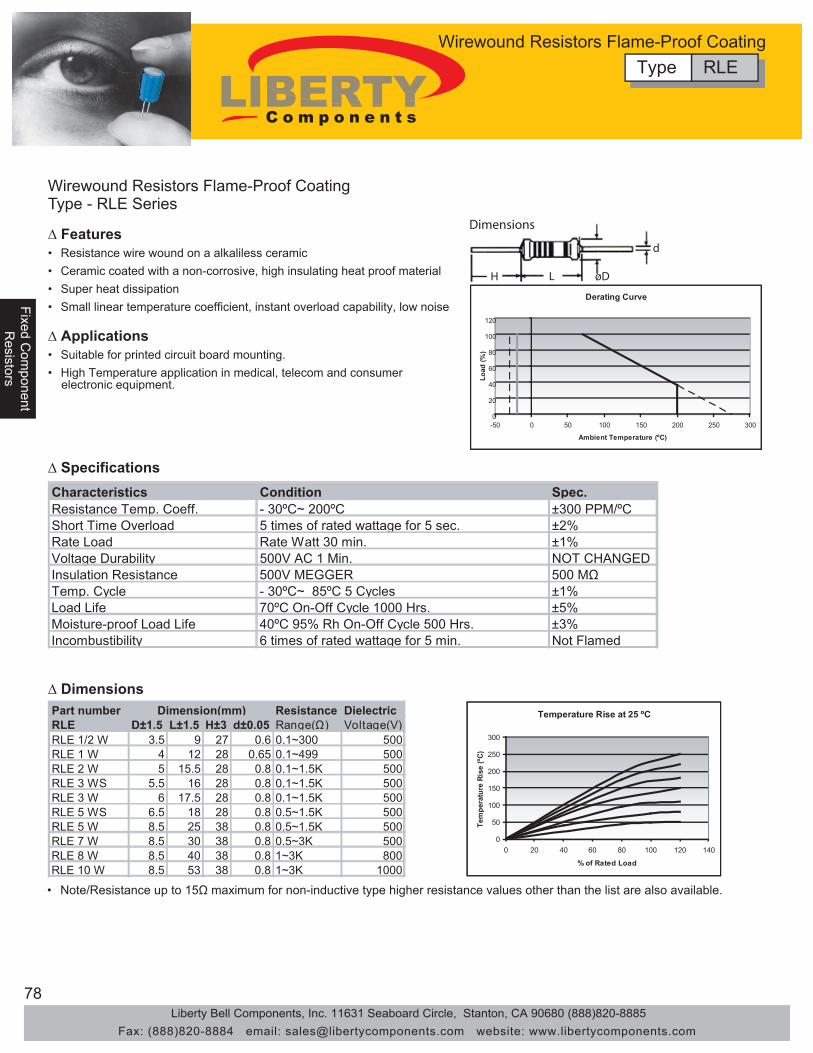
78
Fixed Com
ponentFixed C
omponent
Resistors
Resistors
Fixe
d C
ompo
nent
Res
isto
rs
Wirewound Resistors Flame-Proof CoatingType - RLE Series
• Resistance wire wound on a alkaliless ceramic
• Super heat dissipation
• Suitable for printed circuit board mounting.
• Ceramic coated with a non-corrosive, high insulating heat proof material
• Small linear temperature coefficient, instant overload capability, low noise
Dimensions
H L øD
d
Characteristics Condition Spec. Resistance Temp. Coeff. - 30ºC~ 200ºC ±300 PPM/ºC Short Time Overload 5 times of rated wattage for 5 sec. ±2% Rate Load Rate Watt 30 min. ±1% Voltage Durability 500V AC 1 Min. NOT CHANGED Insulation Resistance 500V MEGGER 500 MΩ Temp. Cycle - 30ºC~ 85ºC 5 Cycles ±1% Load Life 70ºC On-Off Cycle 1000 Hrs. ±5% Moisture-proof Load Life 40ºC 95% Rh On-Off Cycle 500 Hrs. ±3% Incombustibility 6 times of rated wattage for 5 min. Not Flamed
Part number Resistance Dielectric RLE D±1.5 L±1.5 H±3 d±0.05 Range(Ω) Voltage(V) RLE 1/2 W 3.5 9 27 0.6 0.1~300 500 RLE 1 W 4 12 28 0.65 0.1~499 500 RLE 2 W 5 15.5 28 0.8 0.1~1.5K 500 RLE 3 WS 5.5 16 28 0.8 0.1~1.5K 500 RLE 3 W 6 17.5 28 0.8 0.1~1.5K 500 RLE 5 WS 6.5 18 28 0.8 0.5~1.5K 500 RLE 5 W 8.5 25 38 0.8 0.5~1.5K 500 RLE 7 W 8.5 30 38 0.8 0.5~3K 500 RLE 8 W 8.5 40 38 0.8 1~3K 800 RLE 10 W 8.5 53 38 0.8 1~3K 1000
Dimension(mm)
• Note/Resistance up to 15Ω maximum for non-inductive type higher resistance values other than the list are also available.
Derating Curve
0
20
40
60
80
100
120
-50 0 50 100 150 200 250 300
Ambient Temperature (ºC)
Load
(%)
Temperature Rise at 25 ºC
0
50
100
150
200
250
300
0 20 40 60 80 100 120 140
% of Rated Load
Tem
pera
ture
Ris
e (ºC
)
∆ Features
∆ Applications
∆ Specifications
∆ Dimensions
Type RLEWirewound Resistors Flame-Proof Coating
• High Temperature application in medical, telecom and consumer electronic equipment.
Liberty Bell Components, Inc. 11631 Seaboard Circle, Stanton, CA 90680 (888)820-8885Fax: (888)820-8884 email: [email protected] website: www.libertycomponents.com

79
Fixed Com
ponentR
esistors
Fixe
d C
ompo
nent
Fixe
d C
ompo
nent
Res
isto
rsR
esis
tors
Power Type Fixed Wirewound Resistors
• High resistivity to heat, small resistance temp coefficient
• Resistance value unchanged after long use • Change in resistance with temp is linear
• Good resistivity until short time overload
• Load: 1000V 1 Min.
Temperature Characteristics
0
50
100
150
200
250
300
350
0 20 40 60 80 100 120
Percent Rated Power Load
Tem
erat
ure
Rise
(ºC)
L L
L L
W W
g
d D
d1
L1 L2
L1 L2
L1 L2
h h
f
W Ceramic Washer
EH Type EH-A Type EH-B Type EH-C Type
• Insulation: ≥ 500V, 20MΩ
∆ Features
∆ Specifications
40Wd over
15W-30W
10W
5W-7W
Type REHPower Type Fixed Wirewound Resistors
Type - REH Series
• High Power
• Telecom Equipment• Power Supplies
∆ Application
Silicone Coating Type Resist Range: Adjustable Type Special Type WithL D d g W dl f L1 L2 L1 L2 h L1 L2 h Ceramic Coating
EH 5W 0.1Ω ~ 5K(650) 30 12 6 17 5 40 52 45EH 10W 0.1Ω ~ 10K(1.2K) 45 12 6 17 5 55 67 60EH 15W 0.1Ω ~ 15K(1.5K) 45 15 8 19 5 4.1 55 67 60EH 20W 0.1Ω ~ 20K(2.2K) 50 19 10 20 5 4.1 60 77 68 76 38 76 86 38EH 30W 0.1Ω ~ 30K(3.3K) 75 19 10 20 5 4.1 85 105 93 101 38 101 111 38EH 40W 0.1Ω ~ 40K(4.9K) 90 19 10 20 5 4.1 100 115 108 116 38 116 126 38EH 50W 0.1Ω ~ 50K(5.6K) 75 30 16 32 8 5 5.2 89 110 100 117 58 115 131 58 CHT 75WEH 60W 0.1Ω ~ 60K( 7K) 90 30 16 32 8 5 5.2 104 120 115 132 58 130 146 58 CHT 90WEH 80W 0.1Ω ~ 80K( 10K) 115 30 16 32 8 5 5.2 129 150 140 157 58 155 171 58 CHT 120WEH 100W 0.1Ω~100K( 12K) 140 30 16 32 8 5 5.2 154 173 165 182 58 180 196 58 CHT 150WEH 120W 0.1Ω~120K( 15K) 163 30 16 32 8 5 5.2 179 200 188 207 58 203 221 58 CHT 180WEH 150W 0.1Ω~150K( 16K) 195 30 16 32 8 5 5.2 209 230 220 237 58 235 251 58 CHT 225WEH 200W 0.1Ω~200K( 24K) 254 30 16 32 8 5 5.2 268 288 279 296 58 294 310 58 CHT 300WEH 250W 0.1Ω~250K( 30K) 303 30 16 32 8 5 5.2 319 340 328 347 58 343 361 58 CHT 375WEH 300W 0.1Ω~300K( 50K) 254 45 28 47 15 9.15 270 294 314 90 309 330 90 CHT 450WEH 400W 0.1Ω~400K( 60K) 330 45 28 47 15 9.15 345 379 390 90 385 406 90 CHT 600WEH 500W 0.1Ω~500K( 80K) 303 55 35 52 15 9.15 318 343 363 95 358 378 95 CHT 750WEH 600W 0.1Ω~600K( 90K) 330 55 35 52 15 9.15 385 405 95 CHT 850WEH 750W 0.1Ω~750K(100K) 390 55 35 52 15 9.15 445 465 95 CHT1000WEH 1000W 0.1Ω~ 1M(120K) 500 55 35 52 15 9.15 555 575 95 CHT1500WEH 1500W 0.1Ω~ 1.5M(150K) 500 69 40 60 15 9.15 584 608 130 CHT2250WEH 2000W 0.1Ω~ 2M(200K) 650 69 40 60 15 9.15 734 758 130 CHT3000W
Dimension (mm) A Type B Type C Type
Liberty Bell Components, Inc. 11631 Seaboard Circle, Stanton, CA 90680 (888)820-8885Fax: (888)820-8884 email: [email protected] website: www.libertycomponents.com

80
Fixed Com
ponentFixed C
omponent
Resistors
Resistors
Fixe
d C
ompo
nent
Res
isto
rs
High-Power Ribbon Wirewound Resistors
• High resistivity to heat, small resistance temp coefficient
• Resistance value unchanged after long use • Change in resistance with temp is linear
• Good resistivity until short time overload • Insulation: ≥ 500V, 20MΩ • Load: 1000V 1 Min.
Temperature Characteristics
0
50
100
150
200
250
300
350
400
0 20 40 60 80 100 120
Percent Rated Power Load
Tem
pera
ture
Ris
e (ºC
)
Percent Rated Power Load
W
L d
D
g
L L1 L2
L L1 L2
h
W W
L L1 L2
h
f
Ceramic Washer
ER Type ER-A Type ER-B Type ER-C Type
∆ Features
∆ Specifications
Type - RER Series
Type RERHigh-Power Ribbon Wirewound Resistors
• High Power
• Telecom Equipment• Power Supplies
∆ Application
Type Resistant RangeL D d g W dl f L1 L2 L1 L2 h L1 L2 h
ER 120W 0.02Ω ~ 4Ω 115 33 16 32 8 5 5.2 129 150 133 157 58 145 171 58ER 150W 0.03Ω ~ 5Ω 140 33 16 32 8 5 5.2 154 173 158 182 58 170 196 58ER 180W 0.03Ω ~ 6Ω 165 33 16 32 8 5 5.2 179 200 183 207 58 195 221 58ER 225W 0.04Ω ~ 8Ω 195 33 16 32 8 5 5.2 209 230 213 237 58 225 251 58ER 300W 0.05Ω ~ 10Ω 254 33 16 32 8 5 5.2 268 288 272 296 58 285 310 58ER 450W 0.06Ω ~ 12Ω 254 48 28 47 15 9.15 270 274 314 90 290 330 90ER 600W 0.08Ω ~ 15Ω 330 48 28 47 15 9.15 345 349 390 90 365 406 90ER 750W 0.1 Ω ~ 20Ω 303 58 35 52 15 9.15 358 378 95ER 850W 0.2 Ω ~ 25Ω 330 58 35 52 15 9.15 385 405 95ER 1000W 0.3 Ω ~ 30Ω 390 58 35 52 15 9.15 445 465 95ER 1500W 0.4 Ω ~ 35Ω 500 58 35 52 15 9.15 555 575 95ER 2250W 0.5 Ω ~ 40Ω 500 72 40 52 15 9.15 584 608 130ER 3000W 0.7 Ω ~ 50Ω 650 72 40 52 15 9.15 734 758 130
Dimension (mm) A Type B Type C Type
Liberty Bell Components, Inc. 11631 Seaboard Circle, Stanton, CA 90680 (888)820-8885Fax: (888)820-8884 email: [email protected] website: www.libertycomponents.com

81
Fixed Com
ponentR
esistors
Fixe
d C
ompo
nent
Fixe
d C
ompo
nent
Res
isto
rsR
esis
tors
Fusible Wirewound Resistors Type FSQ Series
Characteristics Condition Spec.Operating Temp -40°C ~ 240°CResistance Temp. Coefficient -30°C ~ 150°C ±200ppm/°CShot Time Overload 4 Times of Rated Wattage for 5 Secs. ±2%Insulation Resistance 500V Megger 1,000MΩTemp. Cycle -30°C ~ 85°C for 5 Cycles ±1%Load Life 25°C On-Off Cycle, 1000hrs ±5%Moisture-Proof Load Life 40°C 95% RH On-Off Cycle, 1000hrs ±5%Solder Pot 270°C for 3 Secs ±1%Incombustibility 16 Times of Rated Wattage for 5 Min. Not Flamed
Min 27
Min 27
L W
H
d
*Total Resistance Change / (∆R% + 0.05Ω)
0
20
40
60
80
100
-50 0 50 100 150 200 250 300
Ambient Temperature °C
Rat
ed L
oad
(%)
Test Items Condition Spec.Operating Temp -55°C ~ 275°CResistance Temp. Coefficient -30°C ~ 150°C ±300ppm/°CShot Time Overload 2.5 Times of Rated Wattage for 5 Secs. ±2%Insulation Resistance 500V Megger 1,000MΩTemp. Cycle -30°C ~ 85°C for 5 Cycles ±1%Load Life 70°C On-Off Cycle, 1000hrs ±5%Moisture-Proof Load Life 40°C 95% RH On-Off Cycle, 1000hrs ±5%Solder Pot 270°C for 3 Secs ±1%Incombustibility 16 Times of Rated Wattage for 5 Min. Not Flamed
∆ Characteristics
∆ Dimensions
Type FSQFusible Wirewound Resistors
L ± 1.5 h ± 0.5 W ± 0.5 H(Min) d ± 0.052W 18 7 7 27 0.65 0.1Ω - 22Ω 1000V3W 22 8 8 27 0.8 0.1Ω - 12Ω 1000V5W 22 9 10 27 0.8 0.2Ω - 12Ω 1000V7W 35 9 10 27 0.8 0.3Ω - 250Ω 1000V
10W 48 9 10 27 0.8 0.3Ω - 500Ω 1000V
Resistance Range
Dielectric Withstanding Voltage
Dimension (mm)
FSQ
Style PowerRating
Liberty Bell Components, Inc. 11631 Seaboard Circle, Stanton, CA 90680 (888)820-8885Fax: (888)820-8884 email: [email protected] website: www.libertycomponents.com

82
Fixed Com
ponentFixed C
omponent
Resistors
Resistors
Fixe
d C
ompo
nent
Res
isto
rs
∆ Specifications
• Thick film resistor network with metal glaze on ceramic substrates
• Combinations of Different Ohmic value are available
• Control circuits of V.T.R. Computer, Air Conditioners, TVs, medical and telecom equipment
• Miniature, High Density Packaging
• High reliability with RUO2 Paste
L T
0.25 ± 0.05
d
f
C
H
1
Dimensions (mm)
Operating Temp. Range -55 ºC ~ + 125 ºC RBT.C.R. B Style Others All Styles
0.2W 0.125W 0.25WRating Ambient Temp. Max. Working Voltage 200VResistance Range R style Others Resistance Tolerance(E-12 Series) 100Ω - 10K 10Ω - 4.7MΩ
100V F=±1%, G=±2%, J=±5%
+ 70 ºC
±100PPM 50 ohm ~ 2.2M ohm±250PPM < 50 ohm or 2.2M ohm
Wattage/ElementRA
Type L T C d f(Max) A Circuit B Circuit (Max) + 0.3 ± 0.05 ± 0.2
- 0.24 pin 10.25 pin 12.76 pin 15.37 pin 17.88 pin 20.4 5.08 7.5 2.5 2.8 0.5 2.549 pin 22.910 pin 25.411 pin 28.012 pin 30.513 pin 33.114 pin 35.6
H (Max)
1 2 3 4 5 n1 2
R
3 4
R
n-1 n
R
A Circuit-Parallel Circuit B Circuit-Isolated Circuit
n=4 through 14pins n=4 through 14pinsResistance Code
ToleranceType of Circuit
Pin one Indicator
A 103 G
Number of Elements,R=n-1
Resistance Code
ToleranceType of Circuit
Pin one Indicator
B 103 G
Number of Elements,R=n/2
R R R R R
∆ Features
∆ Applications
∆ Type of Circuits
∆ Dimensions (mm)
SIP Resistor NetworksType RNL Series
Type RNLSIP Resistor Networks
Liberty Bell Components, Inc. 11631 Seaboard Circle, Stanton, CA 90680 (888)820-8885Fax: (888)820-8884 email: [email protected] website: www.libertycomponents.com

83
Fixed Com
ponentR
esistors
Fixe
d C
ompo
nent
Fixe
d C
ompo
nent
Res
isto
rsR
esis
tors
Item Test Methods SpecificationsResistance Temperature -55 ºC ~ + 125 ºC ± 100ppm/ ºC for 50ohm ~ 2.2MCharacteristic ± 250ppm/ ºC for < 50 ohm 2.2MTemperature Cycling -55 ºC ~ + 125 ºC, for 5 cycle Δ R ±(0.5 % + 0.05Ω)Short-Time Overload Rated Voltage x 2.5 for 5 sec. Δ R ±(0.5 % + 0.05Ω)Resistance to Solering Heat 350 ºC for 3 sec. Δ R ±(0.5 % + 0.05Ω)Insulation Resistance 100V for 1 minute Δ 10,000 Megohm Min.Terminal Strength Tensile: 1Kg, 30 sec. Δ R ±(0.25 % + 0.05Ω)
Bending: 400g, 2 TimesLoad V, Room Temp. 30 min.
Thermal Shock Unload, -55 ºC, 15 min. Δ R ±(0.5 % + 0.05Ω)Over 2 hrs in room temp.
Solderbility 230 ºC ±5 ºC, 3 sec. Covering 95%Moisture Load Life 40 ºC, 90-95% RH rated Voltage Δ R ±(2% + 0.05Ω)
for 1000 hoursLoad Life 70 ºC at Rated Voltage for 1000 hours Δ R ±(2% + 0.05Ω)
160/240 330/390180/390 330/470220/270 1.5K/3.3K220/330 3.0K/6.2K
Derating Curve
0
20
40
60
80
100
120
0 20 40 60 80 100 120 140
Ambient Temperature (ºC)
Rat
ed P
ower
(%)
SeriesRA = Low ProfileRB = High Power
Resistance22 Ohm = 200
100 Ohm = 1011000 Ohm = 102
10 KOhm = 1031 MOhm = 105
ToleranceF = ± 1%G = ± 2%
Number of Pin04 = 4 Pin05 = 5 Pin06 = 6 Pin07 = 7 Pin08 = 8 Pin09 = 9 Pin10 = 10 Pin11 = 11 Pin12 = 12 Pin13 = 13 Pin14 = 14 Pin
RNL 08 472 TA
CircuitsA StyleBCDEPRT
∆ Characteristics
∆ Standard Resistance (ohm) E-12 Series
∆ How to Order
∆ Dual Terminitors (R1/R2) (ohm)
SIP Resistor NetworksType RNL Series
Type RNLSIP Resistor Networks
10 12 15 18 22 27 33 39 47 56 68 82100 120 150 180 220 270 330 390 470 560 680 8201K 1.2K 1.5K 1.8K 2.2K 2.7K 3.3K 3.9K 4.7K 5.6K 6.8K 8.2K10K 12K 15K 18K 22K 27K 33K 39K 47K 56K 68K 82K
100K 120K 150K 180K 220K 270K 330K 390K 470K 560K 680K 820K1M 1.2M 1.5M 1.8M 2.2M
Liberty Bell Components, Inc. 11631 Seaboard Circle, Stanton, CA 90680 (888)820-8885Fax: (888)820-8884 email: [email protected] website: www.libertycomponents.com
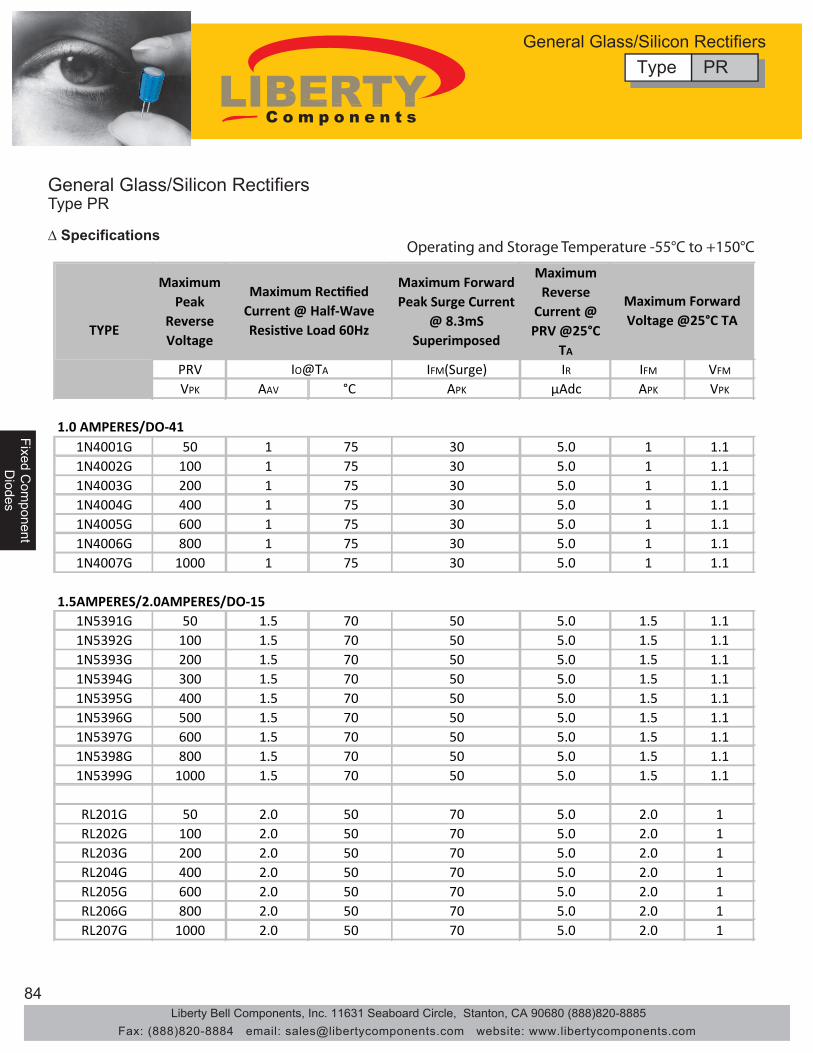
84
Fixed Com
ponentFixed C
omponent
Diodes
Diodes
Fixe
d C
ompo
nent
Dio
des
General Glass/Silicon RectifiersType PR
Operating and Storage Temperature -55°C to +150°C∆ Specifications
MaximumPeak
Reverse Voltage
Maximum Forward Peak Surge Current
@ 8.3mS Superimposed
Maximum Reverse
Current @ PRV @25°C
TA
PRV IFM(Surge) IR IFM VFM
VPK AAV °C APK μAdc APK VPK
1N4001G 50 1 75 30 5.0 1 1.11N4002G 100 1 75 30 5.0 1 1.11N4003G 200 1 75 30 5.0 1 1.11N4004G 400 1 75 30 5.0 1 1.11N4005G 600 1 75 30 5.0 1 1.11N4006G 800 1 75 30 5.0 1 1.11N4007G 1000 1 75 30 5.0 1 1.1
1.5AMPERES/2.0AMPERES/DO-151N5391G 50 1.5 70 50 5.0 1.5 1.11N5392G 100 1.5 70 50 5.0 1.5 1.11N5393G 200 1.5 70 50 5.0 1.5 1.11N5394G 300 1.5 70 50 5.0 1.5 1.11N5395G 400 1.5 70 50 5.0 1.5 1.11N5396G 500 1.5 70 50 5.0 1.5 1.11N5397G 600 1.5 70 50 5.0 1.5 1.11N5398G 800 1.5 70 50 5.0 1.5 1.11N5399G 1000 1.5 70 50 5.0 1.5 1.1
RL201G 50 2.0 50 70 5.0 2.0 1RL202G 100 2.0 50 70 5.0 2.0 1RL203G 200 2.0 50 70 5.0 2.0 1RL204G 400 2.0 50 70 5.0 2.0 1RL205G 600 2.0 50 70 5.0 2.0 1RL206G 800 2.0 50 70 5.0 2.0 1RL207G 1000 2.0 50 70 5.0 2.0 1
Maximum Forward Voltage @25°C TA
Maximum Rectified Current @ Half-Wave Resistive Load 60Hz
IO@TA
TYPE
1.0 AMPERES/DO-41
Type PRGeneral Glass/Silicon Rectifiers
Liberty Bell Components, Inc. 11631 Seaboard Circle, Stanton, CA 90680 (888)820-8885Fax: (888)820-8884 email: [email protected] website: www.libertycomponents.com

85
Fixed Com
ponentD
iodes
Fixe
d C
ompo
nent
Fixe
d C
ompo
nent
Dio
des
Dio
des
General Glass/Silicon RectifiersType PR
Operating and Storage Temperature -55°C to +150°C∆ Specifications
MaximumPeak
Reverse Voltage
Maximum Forward Peak Surge Current
@ 8.3mS Superimposed
Maximum Reverse
Current @ PRV @25°C
TA
PRV IFM(Surge) IR IFM VFM
VPK AAV °C APK μAdc APK VPK
RL251G 50 2.5 70 70 5.0 2.5 1.0RL252G 100 2.5 70 70 5.0 2.5 1.0RL253G 200 2.5 70 70 5.0 2.5 1.0RL254G 400 2.5 70 70 5.0 2.5 1.0RL255G 600 2.5 70 70 5.0 2.5 1.0RL256G 800 2.5 70 70 5.0 2.5 1.0RL257G 1000 2.5 70 70 5.0 2.5 1.0
1N5400G 50 3.0 50 200 5.0 3.0 1.21N5401G 100 3.0 50 200 5.0 3.0 1.21N5402G 200 3.0 50 200 5.0 3.0 1.21N5403G 300 3.0 50 200 5.0 3.0 1.21N5404G 400 3.0 50 200 5.0 3.0 1.21N5405G 500 3.0 50 200 5.0 3.0 1.21N5406G 600 3.0 50 200 5.0 3.0 1.21N5407G 800 3.0 50 200 5.0 3.0 1.21N5408G 1000 3.0 50 200 5.0 3.0 1.2
P600AG 50 6 60 400 10 6 0.95P600BG 100 6 60 400 10 6 0.95P600DG 200 6 60 400 10 6 0.95P600GG 400 6 60 400 10 6 0.95P600JG 600 6 60 400 10 6 0.95P600KG 800 6 60 400 10 6 0.95P600MG 1000 6 60 400 10 6 0.95
6.0AMPERES/R-6
Maximum Forward Voltage @25°C TA
Maximum Rectified Current @ Half-Wave Resistive Load 60Hz
IO@TA
TYPE
2.5 AMPERES/R-3
3.0AMPERES/DO-27
Type PRGeneral Glass/Silicon Rectifiers
Liberty Bell Components, Inc. 11631 Seaboard Circle, Stanton, CA 90680 (888)820-8885Fax: (888)820-8884 email: [email protected] website: www.libertycomponents.com

86
Fixed Com
ponentFixed C
omponent
Diodes
Diodes
Fixe
d C
ompo
nent
Dio
des
Glass/Silicon Passivated RectifiersType PR - 1N5391(G/S) Thru 1N5399(G/S)
∆ Features● Low cost● Diffused junction● Low forward voltage drop● Low reverse leakage current● High current capability● The plastic material carries UL recognition 94V-0
∆ Mechanical Data●Case: JEDEC DO-41 molded plastic●Polarity: Color band denotes cathode●Weight: 0.012 ounces, 0.34 grams●Mounting position: Any
Ratings ar 25°C ambient temperature unless otherwise specified.
Single phase, half wave, 60Hz, resistive or inductive load.
For capacitance load, derate current by 20%
∆ Maximum Ratings and Electrical Characteristics
Reverse Voltage - 50 to 1000 VoltsForward Current - 1.5 Amperes
Dimensions in inches and (millimeters)
DO-15
.140(3.6)
.104(2.6)
DI.034(0.9).028(0.7)
DI
.300(7.6)
.230(5.8)
1.0(25.4MIN
1.0(25.4MIN
1N 1N 1N 1N 1N 1N 1N 1N 1N5391 5392 5393 5394 5395 5396 5397 5398 5399
Maximum Recurrent Peak Reverse Voltage VRRM 50 100 200 300 400 500 600 800 1000 V
Maximum RMS Voltage VRMS 35 70 140 210 280 350 420 560 700 V
Maximum DC Blocking Voltage VDC 50 100 200 300 400 500 600 800 1000 V
Maximum Average ForwardRectified Current @TA =70 °CPeak Forward Surge Current8.3ms Single Half Sine-WaveSuper Imposed on Rated Load(JEDEC Method)
Maximum Forward Voltage at 1.5A DC VF V
Maximum DC Reverse Current @TJ=25°Cat Rated DC Blocking Voltage @TJ=100°C
Typical Junction Capacitance (Note1) CJ pF
Typical Thermal Resistance (Note2) RθJA °C/W
Operating Temperature Range TJ °C
Storage Temperature Range TSTG °C
IR50
uA
IFSM A50
1.1
5.0
20
26
-55 to +150
-55 to +150
NOTES:1.Measured at 1.0 MHz and applied reverse voltage of 4.0V DC
2.Thermal resistance junction of lead.
CHARACTERISTICS
I(AV) 1.5 A
SYMBOL UNIT
Type PRGlass/Silicon Passivated Rectifiers
1N5391(G/S) Thru 1N5399(G/S)
Liberty Bell Components, Inc. 11631 Seaboard Circle, Stanton, CA 90680 (888)820-8885Fax: (888)820-8884 email: [email protected] website: www.libertycomponents.com

87
Fixed Com
ponentD
iodes
Fixe
d C
ompo
nent
Fixe
d C
ompo
nent
Dio
des
Dio
des
Glass/Silicon Passivated RectifiersType PR - 1N5391(G/S) Thru 1N5399(G/S)
∆ Rating and Characteristics CurvesFIG. 1 – FORWARD CURRENT DERATING CURVE
LEAD TEMPERATURE (°C)
AV
ER
AG
EFO
RW
AR
DC
UR
RE
NT
(AM
PE
RE
S)
1.0
0.5
025
1.5
15050 12575 175100
SINGLE PHASE HALF WAVE 60HzRESISTIVE OR INDUCTIVE LOAD
0.375"(9.5mm)LEAD LENGTHS
FIG. 2 – MAXIMUM NON-REPETITIVE SURGE CURRENT
NUMBER OF CYCLES AT 60Hz
PE
AK
FOR
WA
RD
SU
RG
EC
UR
RE
NT
(AM
PE
RE
S)
PULSE WIDTH 8.3msSINGLE HALF-SINE-WAVE
(JEDEC METHOD)
1
50
40
30
20
10
0
60
2 5 10 20 50 100
FIG.3 – TYPICAL JUNCTION CAPACITANCE
CA
PA
CIT
AN
CE
(pF)
REVERSE VOLTAGE ,VOLTS
1
100
10
04 10 100
TJ = 25°Cf = 1 MHz
FIG.4-TYPICAL FORWARD CHARACTERISTICS
INST
ANTA
NE
OU
SFO
RW
ARD
CU
RR
ENT,
(A)
INSTANTANEOUS FORWARD VOLTAGE,VOLTS
0
0.1
1.0
0.01
10
0 .2 0.4 0.6 0.8 1.0 1.2 1.4 1.6 1.8
TJ = 25°C
PULSE WIDTH 300us
Type PRGlass/Silicon Passivated Rectifiers
1N5391(G/S) Thru 1N5399(G/S)
Liberty Bell Components, Inc. 11631 Seaboard Circle, Stanton, CA 90680 (888)820-8885Fax: (888)820-8884 email: [email protected] website: www.libertycomponents.com
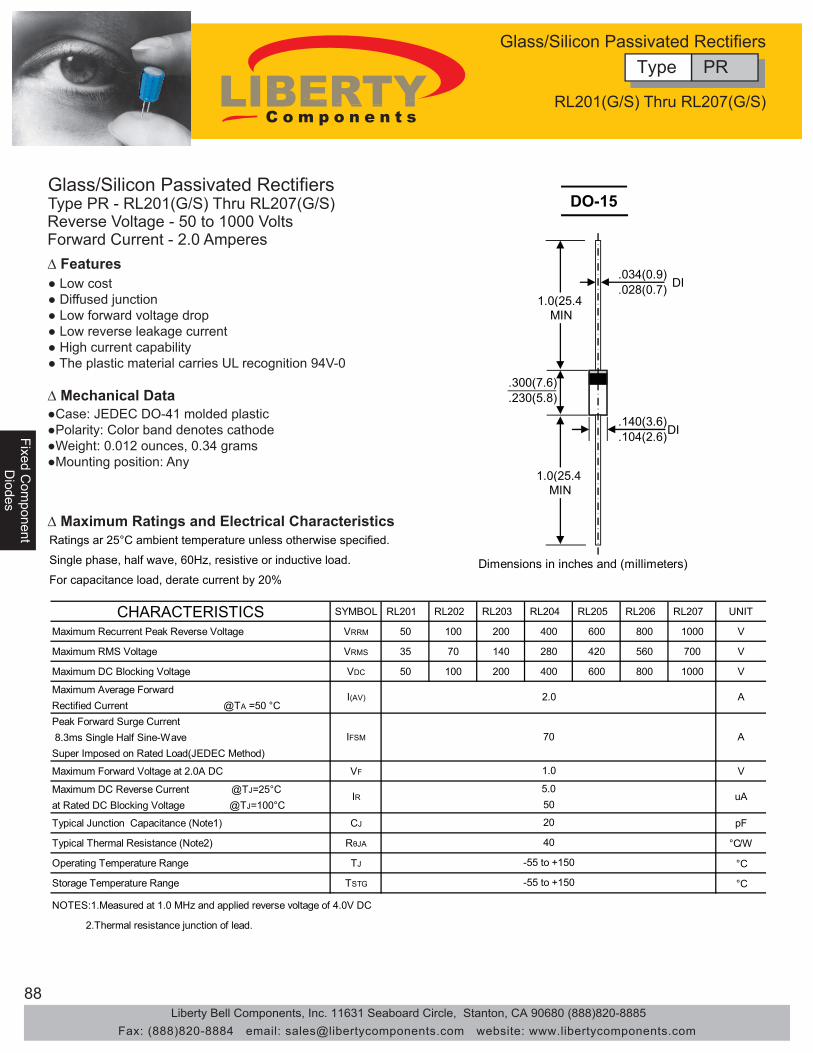
88
Fixed Com
ponentFixed C
omponent
Diodes
Diodes
Fixe
d C
ompo
nent
Dio
des
Glass/Silicon Passivated RectifiersType PR - RL201(G/S) Thru RL207(G/S)
∆ Features● Low cost● Diffused junction● Low forward voltage drop● Low reverse leakage current● High current capability● The plastic material carries UL recognition 94V-0
∆ Mechanical Data●Case: JEDEC DO-41 molded plastic●Polarity: Color band denotes cathode●Weight: 0.012 ounces, 0.34 grams●Mounting position: Any
Ratings ar 25°C ambient temperature unless otherwise specified.
Single phase, half wave, 60Hz, resistive or inductive load.
For capacitance load, derate current by 20%
∆ Maximum Ratings and Electrical Characteristics
Reverse Voltage - 50 to 1000 VoltsForward Current - 2.0 Amperes
Dimensions in inches and (millimeters)
DO-15
.140(3.6)
.104(2.6)
DI.034(0.9).028(0.7)
DI
.300(7.6)
.230(5.8)
1.0(25.4MIN
1.0(25.4MIN
CHARACTERISTICS SYMBOL RL201 RL202 RL203 RL204 RL205 RL206 RL207 UNIT
Maximum Recurrent Peak Reverse Voltage VRRM 50 100 200 400 600 800 1000 V
Maximum RMS Voltage VRMS 35 70 140 280 420 560 700 V
Maximum DC Blocking Voltage VDC 50 100 200 400 600 800 1000 V
Maximum Average ForwardRectified Current @TA =50 °CPeak Forward Surge Current8.3ms Single Half Sine-WaveSuper Imposed on Rated Load(JEDEC Method)
Maximum Forward Voltage at 2.0A DC VF V
Maximum DC Reverse Current @TJ=25°Cat Rated DC Blocking Voltage @TJ=100°C
Typical Junction Capacitance (Note1) CJ pF
Typical Thermal Resistance (Note2) RθJA °C/W
Operating Temperature Range TJ °C
Storage Temperature Range TSTG °C
40
-55 to +150
-55 to +150
NOTES:1.Measured at 1.0 MHz and applied reverse voltage of 4.0V DC
2.Thermal resistance junction of lead.
1.0
5.0
20
70 A
I(AV) 2.0 A
IR uA50
IFSM
Type PRGlass/Silicon Passivated Rectifiers
RL201(G/S) Thru RL207(G/S)
Liberty Bell Components, Inc. 11631 Seaboard Circle, Stanton, CA 90680 (888)820-8885Fax: (888)820-8884 email: [email protected] website: www.libertycomponents.com

89
Fixed Com
ponentD
iodes
Fixe
d C
ompo
nent
Fixe
d C
ompo
nent
Dio
des
Dio
des
Glass/Silicon Passivated RectifiersType PR - RL201(G/S) Thru RL207(G/S)
∆ Rating and Characteristics CurvesFIG. 1 – FORWARD CURRENT DERATING
AMBIENT TEMPERATURE (°C)
AV
ER
AG
EFO
RW
AR
DC
UR
RE
NT
(AM
PE
RE
S)
1.0
0.5
025
3.0
1.5
2.0
2.5
50 12510075 150 175
SINGLE PHASE HALF WAVE 60HzRESISTIVE OR INDUCTIVE LOAD
NUMBER OF CYCLES AT 60Hz
FIG. 2 – MAXIMUM NON-REPETITIVE SURGE CURRENT
PEAK
FOR
WAR
DSU
RG
EC
UR
REN
T(A
MPE
RES
)1
5040
30
20
100
60
2 5 10 20 10050
70
PULSE WIDTH 8.3msSINGLE HALF-SINE-WAVE
(JEDEC METHOD)
CA
PA
CIT
AN
CE
(pF)
FIG.3 – TYPICAL JUNCTION CAPACITANCE
REVERSE VOLTAGE ,VOLTS
1
100
10
14 10 100
TJ = 25°Cf = 1 MHz
FIG.4-TYPICAL FORWARD CHARACTERISTICS
INS
TAN
TAN
EO
US
FOR
WA
RD
CU
RR
EN
T,(A
)
INSTANTANEOUS FORWARD VOLTAGE, VOLTS
0
0.1
1.0
0.01
10
0.2 0.4 0.6 0.8 1.2 1.61.41.0 1.8
TJ= 25°C
PULSE WIDTH 300us
Type PRGlass/Silicon Passivated Rectifiers
RL201(G/S) Thru RL207(G/S)
Liberty Bell Components, Inc. 11631 Seaboard Circle, Stanton, CA 90680 (888)820-8885Fax: (888)820-8884 email: [email protected] website: www.libertycomponents.com

90
Fixed Com
ponentFixed C
omponent
Diodes
Diodes
Fixe
d C
ompo
nent
Dio
des
Glass/Silicon Passivated RectifiersType PR - 1N5400(G/S) Thru 1N5408G(G/S)
∆ Features● Low cost● Diffused junction● Low forward voltage drop● Low reverse leakage current● High current capability● The plastic material carries UL recognition 94V-0
∆ Mechanical Data●Case: JEDEC DO-27 molded plastic●Polarity: Color band denotes cathode●Weight: 0.04 ounces, 1.1 grams●Mounting position: Any
Ratings ar 25°C ambient temperature unless otherwise specified.
Single phase, half wave, 60Hz, resistive or inductive load.
For capacitance load, derate current by 20%
∆ Maximum Ratings and Electrical Characteristics
Reverse Voltage - 50 to 1000 VoltsForward Current - 3.0 Amperes
Dimensions in inches and (millimeters)
DO- 27
DIA.
DIA.
210.375(9.5).335(8.5)
.052(1.3)
.048(1.2)
.220(5.6)
.197(5.0)
1.0(25.4)
1.0(25.4)
MI
MI
1N 1N 1N 1N 1N 1N 1N 1N 1N5400 5401 5402 5403 5404 5405 5406 5407 5408
Maximum Recurrent Peak Reverse Voltage VRRM 50 100 200 300 400 500 600 800 1000 V
Maximum RMS Voltage VRMS 35 70 140 210 280 350 420 560 700 V
Maximum DC Blocking Voltage VDC 50 100 200 300 400 500 600 800 1000 V
Maximum Average ForwardRectified Current @TA =55°CPeak Forward Surge Current8.3ms Single Half Sine-WaveSupe Imposed on Rated Load(JEDEC Method)
Maximum Forward Voltage at 3.0A DC VF V
Maximum DC Reverse Current @TJ=25at Rated DC Blocking Voltage @TJ=100
Typical Junction Capacitance (Note1) CJ pF
Typical Thermal Resistance (Note2) RθJA /W
Operating Temperature Range TJ
Storage Temperature Range TSTG
200IFSM
SYMBOLCHARACTERISTICS
IR5.0
uA
3550
I(AV) A
UNIT
1.2
50
3.0
A
15
-55 to +150
-55 to +150
NOTES:1.Measured at 1.0 MHz and applied reverse voltage of 4.0V DC2.Thermal resistance junction of ambient.
°C°C
°C°C
°C
Type PRGlass/Silicon Passivated Rectifiers
1N5400(G/S) Thru 1N5408G(G/S)
Liberty Bell Components, Inc. 11631 Seaboard Circle, Stanton, CA 90680 (888)820-8885Fax: (888)820-8884 email: [email protected] website: www.libertycomponents.com

91
Fixed Com
ponentD
iodes
Fixe
d C
ompo
nent
Fixe
d C
ompo
nent
Dio
des
Dio
des
Glass/Silicon Passivated RectifiersType PR - 1N5400(G/S) Thru 1N5408(G/S)
∆ Rating and Characteristics Curves
FIG. 1 – FORWARD CURRENT DERATING CURVE
AMBIENT TEMPERATURE ( )
AV
ER
AG
EFO
RW
AR
DC
UR
RE
NT
(AM
PE
RE
S)
1.0
0.5
025
3.0
1.5
2.0
2.5
50 12510075 150 175
SINGLE PHASE HALF WAVE 60HzRESISTIVE OR INDUCTIVE LOAD
1
150
100
50
0
200
2 5 10 20 50 100
NUMBER OF CYCLES AT 60Hz
FIG. 2 – MAXIMUM NON-REPETITIVE SURGE CURRENT
PE
AK
FOR
WA
RD
SU
RG
EC
UR
RE
NT
(AM
PE
RE
S)
PULSE WIDTH 8.3msSINGLE HALF-SINE-WAVE
(JEDEC METHOD)
FIG.3 – TYPICAL JUNCTION CAPACITANCE
CA
PA
CIT
AN
CE
,(pF
)
REVERSE VOLTAGE,VOLTS
1
100
10
14 10 100
1N5400G TO 1N5405G
1N5406G TO 1N5408G
TJ = 25°Cf = 1 MHZ
FIG.4-TYPICAL FORWARD CHARACTERISTICS
INS
TAN
TAN
EO
US
FOR
WA
RD
CU
RR
EN
T,(A
)
INSTANTANEOUS FORWARD VOLTAGE,VOLTS
0
1.0
10
0.1
100
0.2 0.4 0.6 0.8 1.2 1.61.41.0 1.8
TJ = 25°C
PULSE WIDTH 300us
°C
Type PRGlass/Silicon Passivated Rectifiers
1N5400(G/S) Thru 1N5408(G/S)
Liberty Bell Components, Inc. 11631 Seaboard Circle, Stanton, CA 90680 (888)820-8885Fax: (888)820-8884 email: [email protected] website: www.libertycomponents.com

92
Fixed Com
ponentFixed C
omponent
Diodes
Diodes
Fixe
d C
ompo
nent
Dio
des
Glass/Silicon Passivated RectifiersType PR - 1N4001(G/S) Thru 1N4007(G/S)
∆ Features● Low cost● Diffused junction● Low forward voltage drop● Low reverse leakage current● High current capability● The plastic material carries UL recognition 94V-0
∆ Mechanical Data●Case: JEDEC DO-41 molded plastic●Polarity: Color band denotes cathode●Weight: 0.012 ounces, 0.34 grams●Mounting position: Any
Ratings ar 25°C ambient temperature unless otherwise specified.
Single phase, half wave, 60Hz, resistive or inductive load.
For capacitance load, derate current by 20%
∆ Maximum Ratings and Electrical Characteristics
Reverse Voltage - 50 to 1000 VoltsForward Current - 1.0 Amperes
Dimensions in inches and (millimeters)
DO- 41
.107(2.7)
.080(2.0)
.034(0.9)
.028(0.7) DIA
DIA
.205(5.2)MAX
1.0(25.4)MIN.
1.0(25.4)MIN.
CHARACTERISTICS SYMBOL 1N4001 1N4002 1N4003 1N4004 1N4005 1N4006 1N4007 UNIT
Maximum Recurrent Peak Reverse Voltage VRRM 50 100 200 400 600 800 1000 V
Maximum RMS Voltage VRMS 35 70 140 280 420 560 700 V
Maximum DC Blocking Voltage VDC 50 100 200 400 600 800 1000 V
Maximum Average ForwardRectified Current @TA=75 °CPeak Forward Surge Current8.3ms Single Half Sine-WaveSuper Imposed On Rated Load (JEDEC Method)
Maximum Forward Voltage at 1.0A DC VF V
Maximum DC Reverse Current @TJ=25°Cat Rated DC Blocking Voltage @TJ=100°C
Typical Junction Capacitance (Note1) CJ pF
Typical Thermal Resistance (Note2) RθJC °C /W
Operating Temperature Range TJ °C
Storage Temperature Range TSTG °C
A
30
15
50
-55 to +150
-65 to +175
NOTES:1.Measured at 1.0 MHz and applied reverse voltage of 4.0V DC
2.Thermal resistance junction of ambient .375“(9.5mm) lead length
1.1
IR505.0
uA
IFSM A
I(AV) 1.0
Type PRGlass/Silicon Passivated Rectifiers
1N4001(G/S) Thru 1N4007(G/S)
Liberty Bell Components, Inc. 11631 Seaboard Circle, Stanton, CA 90680 (888)820-8885Fax: (888)820-8884 email: [email protected] website: www.libertycomponents.com

93
Fixed Com
ponentD
iodes
Fixe
d C
ompo
nent
Fixe
d C
ompo
nent
Dio
des
Dio
des
Glass/Silicon Passivated RectifiersType PR - 1N4001(G/S) Thru 1N4007(G/S)
∆ Rating and Characteristics Curves
NUMBER OF CYCLES AT 60Hz
FIG. 2 - MAXIMUM NON-REPETITIVE SURGE CURRENT
PE
AK
FOR
WA
RD
SU
RG
EC
UR
RE
NT
AM
PE
RE
S
PULSE WIDTH 8.3msSINGLE HALF-SINE-WAVE
(JEDEC METHOD)
50
40
30
20
10
01 2 5 10 20 50 100
INSTANTANEOUS FORWARD VOLTAGE, VOLTS
INS
TAN
TAN
EO
US
FOR
WA
RD
CU
RR
EN
T(A
)
FIG.4 - TYPICAL FORWARD CHARACTERISTICS
PULSE WIDTH 300us
TJ = 25°
10
0
0.1
1.0
0.01
0.2 0.60.4 0.8 1.2 1.61.4 1.81.0
TJ = 25°Cf = 1 MHz
4
100
10
60
40
20
4
2
14010 1001
REVERSE VOLTAGE, VOLTS
CA
PA
CIT
AN
CE
,(pF)
FIG. 3 - TYPICAL JUNCTION CAPACITANCE
25 50 75 100 125 150 175
1.0
0.8
0.6
0.4
0.2
0
SINGLE PHASE HALF WAVE 60Hz RESISTIVE OR INDUCTIVE LOAD
FIG. 1 - FORWARD CURRENT DERATING CURVE
AV
ER
AG
EFO
RW
AR
DC
UR
RE
NT
AM
PE
RE
S
AMBIENT TEMPERATURE. °C
Type PRGlass/Silicon Passivated Rectifiers
1N4001(G/S) Thru 1N4007(G/S)
Liberty Bell Components, Inc. 11631 Seaboard Circle, Stanton, CA 90680 (888)820-8885Fax: (888)820-8884 email: [email protected] website: www.libertycomponents.com
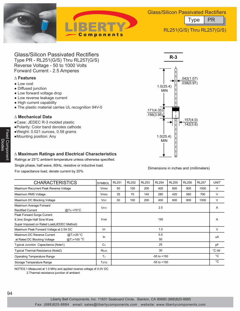
94
Fixed Com
ponentFixed C
omponent
Diodes
Diodes
Fixe
d C
ompo
nent
Dio
des
Glass/Silicon Passivated RectifiersType PR - RL251(G/S) Thru RL257(G/S)
∆ Features● Low cost● Diffused junction● Low forward voltage drop● Low reverse leakage current● High current capability● The plastic material carries UL recognition 94V-0
∆ Mechanical Data●Case: JEDEC R-3 molded plastic●Polarity: Color band denotes cathode●Weight: 0.021 ounces, 0.58 grams●Mounting position: Any
Dimensions in inches and (millimeters)
.157(4.0)
.142(3.6)
.042(1.07)
.038(0.97)
.171(4.35)
.156(3.95)
1.0(25.4)MIN
1.0(25.4)MIN
R-3
Ratings ar 25°C ambient temperature unless otherwise specified.
Single phase, half wave, 60Hz, resistive or inductive load.
For capacitance load, derate current by 20%
CHARACTERISTICS SYMBOL RL251 RL252 RL253 RL254 RL255 RL256 RL257 UNIT
Maximum Recurrent Peak Reverse Voltage VRRM 50 100 200 400 600 800 1000 V
Maximum RMS Voltage VRMS 35 70 140 280 420 560 700 V
Maximum DC Blocking Voltage VDC 50 100 200 400 600 800 1000 V
Maximum Average ForwardRectified Current @TA =70°CPeak Forward Surge Current8.3ms Single Half Sine-WaveSuper Imposed on Rated Load(JEDEC Method)
Maximum Peak Forward Voltage at 2.5A DC VF V
Maximum DC Reverse Current @TJ=25at Rated DC Blocking Voltage @TJ=100
Typical Junction Capacitance (Note1) CJ pF
Typical Thermal Resistance (Note2) RθJA /W
Operating Temperature Range TJ
Storage Temperature Range TSTG
IFSM 150
IR50
30
2.Thermal resistance junction of ambient.
-55 to +150
-55 to +150
NOTES:1.Measured at 1.0 MHz and applied reverse voltage of 4.0V DC
I(AV) 2.5 A
1.0
5.0
25
A
uA
∆ Maximum Ratings and Electrical Characteristics
Reverse Voltage - 50 to 1000 VoltsForward Current - 2.5 Amperes
°C°C
°C
°C
°C
Type PRGlass/Silicon Passivated Rectifiers
RL251(G/S) Thru RL257(G/S)
Liberty Bell Components, Inc. 11631 Seaboard Circle, Stanton, CA 90680 (888)820-8885Fax: (888)820-8884 email: [email protected] website: www.libertycomponents.com

95
Fixed Com
ponentD
iodes
Fixe
d C
ompo
nent
Fixe
d C
ompo
nent
Dio
des
Dio
des
Glass/Silicon Passivated RectifiersType PR - RL251(G/S) Thru RL257(G/S)
∆ Rating and Characteristics Curves
NUMBER OF CYCLES AT 60Hz
FIG. 2 – MAXIMUM NON-REPETITIVE SURGE CURRENT
PE
AK
FOR
WA
RD
SU
RG
EC
UR
RE
NT
(AM
PE
RE
S)
1
150
100
50
0
200
2 4 10 20 40 100
PULSE WIDTH 8.3msSINGLE HALF-SINE-WAVE
(JEDEC METHOD)
FIG.3 – TYPICAL JUNCTION CAPACITANCE
CA
PA
CIT
AN
CE
(pF)
REVERSE VOLTAGE,VOLTS
100
10
1
60
40
20
2
4
4 .2 .4 20 4021.0 100.1
TJ = 25°Cf = 1 MHz
FIG.4-TYPICAL FORWARD CHARACTERISTICS
INS
TAN
TAN
EO
US
FOR
WA
RD
CU
RR
EN
T,(A
)
INSTANTANEOUS FORWARD VOLTAGE,VOLTS
0
0.1
1.0
0.01
10
0.2 0.4 0.6 0.8 1.2 1.61.41.0 1.8
TJ = 25°C
PULSE WIDTH 300us
FIG. 1 – FORWARD CURRENT DERATING
LEAD TEMPERATURE (°C)
AV
ER
AG
EFO
RW
AR
DC
UR
RE
NT
(AM
PE
RE
S)
1.0
0.5
025
3.0
1.5
2.0
2.5
50 12510075 150 175
SINGLE PHASE HALF WAVE 60HzRESISTIVE OR INDUCTIVE LOAD
Type PRGlass/Silicon Passivated Rectifiers
RL251(G/S) Thru RL257(G/S)
Liberty Bell Components, Inc. 11631 Seaboard Circle, Stanton, CA 90680 (888)820-8885Fax: (888)820-8884 email: [email protected] website: www.libertycomponents.com

96
Fixed Com
ponentFixed C
omponent
Diodes
Diodes
Fixe
d C
ompo
nent
Dio
des
Glass/Silicon Passivated RectifiersType PR - P600A(G/S) Thru P600M(G/S)
∆ Features● Low cost● Diffused junction● Low forward voltage drop● Low reverse leakage current● High current capability● The plastic material carries UL recognition 94V-0
∆ Mechanical Data●Case: JEDEC R-6 molded plastic●Polarity: Color band denotes cathode●Weight: 0.07 ounces, 2.1 grams●Mounting position: Any
Ratings ar 25°C ambient temperature unless otherwise specified.
Single phase, half wave, 60Hz, resistive or inductive load.
∆ Maximum Ratings and Electrical Characteristics
Reverse Voltage - 50 to 1000 VoltsForward Current - 6.0 Amperes
Dimensions in inches and (millimeters)
R - 6
2100.360(9.1).340(8.6)
.052(1.3)
.048(1.2) DIA
.360(9.1)
.340(8.6) DIA
1.0(25.4)MIN
1.0(25.4)MIN
CHARACTERISTICS SYMBOL P600A P600B P600D P600G P600J P600K P600M UNIT
Maximum Recurrent Peak Reverse Voltage VRRM 50 100 200 400 600 800 1000 V
Maximum RMS Voltage VRMS 35 70 140 280 420 560 700 V
Maximum DC Blocking Voltage VDC 50 100 200 400 600 800 1000 V
Maximum Average ForwardRectified Current @TA =60°CPeak Forward Surge Current8.3ms Single Half Sine-WaveSuper Imposed on Rated Load(JEDEC Method)
Maximum Forward Voltage at 6.0A DC VF V
Maximum DC Reverse Current @TJ=25°Cat Rated DC Blocking Voltage @TJ=100°CTypical Junction Capacitance (Note1) CJ pF
Typical Thermal Resistance (Note2) RθJA °C /W
Operating Temperature Range TJ °CStorage Temperature Range TSTG °C
IR uA
100
10
100
-55 to +150
-55 to +150
NOTES:1.Measured at 1.0 MHz and applied reverse voltage of 4.0V DC2.Thermal resistance junction of lead.
6.0
400
AI(AV)
IFSM A
0.95
10
Type PRGlass/Silicon Passivated Rectifiers
P600A(G/S) Thru P600M(G/S
Liberty Bell Components, Inc. 11631 Seaboard Circle, Stanton, CA 90680 (888)820-8885Fax: (888)820-8884 email: [email protected] website: www.libertycomponents.com

97
Fixed Com
ponentD
iodes
Fixe
d C
ompo
nent
Fixe
d C
ompo
nent
Dio
des
Dio
des
Glass/Silicon Passivated RectifiersType PR - P600A(G/S) Thru P600M(G/S)
∆ Rating and Characteristics CurvesFIG. 1 – FORWARD CURRENT DERATING CURVE
AMBIENT TEMPERATURE
AV
ER
AG
EFO
RW
AR
DC
UR
RE
NT
AM
PE
RE
S
5.0
3.0
00
4.0
2.0
1.0
25 75 12550 100 150
6.0
SINGLE PHASE HALF WAVE 60HzRESISTIVE OR INDUCTIVE LOAD
FIG.3 – TYPICAL JUNCTION CAPACITANCE
CA
PA
CIT
AN
CE
,(pF
)
REVERSE VOLTAGE,VOLTS
1000
100
10
1 4 10 100
TJ = 25°Cf = 1 MHz
NUMBER OF CYCLES AT 60Hz
FIG. 2 – MAXIMUM NON-REPETITIVE SURGE CURRENT
PE
AK
FOR
WA
RD
SU
RG
EC
UR
RE
NT
AM
PE
RE
S
1
300
200
100
0
400
2 5 10 20 50 100
PULSE WIDTH 8.3msSINGLE HALF-SINE -WAVE
(JEDEC METHOD)
FIG.4-TYPICAL FORWARD CHARACTERISTICS
INST
ANTA
NE
OU
SFO
RW
ARD
CU
RR
ENT,
(A)
INSTANTANEOUS FORWARD VOLTAGE,VOLTS
1.0
10
0.1
100
0 0.2 0.4 0.6 0.8 1.2 1.61.41.0 1.8
TJ = 25°C
PULSE WIDTH 300us
(°C)
Type PRGlass/Silicon Passivated Rectifiers
P600A(G/S) Thru P600M(G/S)
Liberty Bell Components, Inc. 11631 Seaboard Circle, Stanton, CA 90680 (888)820-8885Fax: (888)820-8884 email: [email protected] website: www.libertycomponents.com

98
Surface M
ountS
urface Mount
Capacitors
Capacitors
Sur
face
Mou
ntC
apac
itors
• General electronic equipment.• Class I (T.C. Type) Temperature compensation.• Class I (T.C. Type) Tuned Circuits and Filters.• Class II (Hi-K type) By pass and coupling.
CMC 0805 CG 102 J 1H
(1) Type(2) EIA size code(3) Temperature characteristics(4) Nominal capacitance(5) Capacitance tolerance(6) Rated voltage
(1) (2) (3) (4) (5)(6)
5. External Electrode Solder
1 2 5 4 3
NO. Name Material1. Ceramic Dielectric Ceramics2. Inner Electrode Palladium3. Substrate Electrode Silver4. Intermediate Electrode Nickel
Class I (Temperature compensating type)
Class II (High dielectric constant type)
Code C0G(CG)Temp. range -55 to 125°CTemp. Coeff. 0 ± 30ppm/°C
Code X7R(XR) Z5U(ZU) Y5V(YV)Temp. range -55 to 125°C +10 to 85°C -30 to 85°CCap. change ±15% +22 to -56% +22 to -82%
(4) Nominal Capacitance DesignationStated in three digits and in units of pico farads (pF).The capacitance shall be expressed in a 3 digits code.The first and second digits identify the first and secondsignificant figures of the capacitance, the third digitidentifies the multiplier. However, when capacitance isbelow 10pF there are decimal digits included, they arestated as D. Please check examples below:Symbol Capacitance (pF)D50 0.5D75 0.751D5 1.5100 10101 100
(3) Temperature characteristics
∆ Features• Small in size and wide capacitance range.• Superior humidity characteristic and long life thanks to the monolithic construction.• Three layer terminals are made of metal, excellent solderability and high resistance to migration.• Low inductance and excellent frequency characteristics enable a circuit with parameters nearly to the designed theoretical values.
∆ Part Numbering
∆ Applications
∆ Construction
Nickel Barrier Termination Type
(5) Capacitance Tolerance
(6) Rated VoltageJ = ±5% K = ±10%
1H = 50V
Type CMCMultilayer Ceramic Chip Capacitors
"T"
Size
0402
0603
0805
1206
1210
1812
2220
Dimensions in (mm) [Brackets indicate in inches]L W T max. B min. G min.
1±0.05 0.5±0.05 0.5 0.15 0.3[0.39±.002] [0.20±.002] [0.20] [.006] [0.12]
1.6±0.1 0.8±0.1 0.9 0.2 0.3[.063±.004] [.031±.004] [.035] [.008] [.012]
2.0±0.2 1.25±0.2 1.45 0.2 0.5[.079±.008] [.049±.008] [.057] [.008] [.020]3.2±0.2 1.6±0.2 1.30 0.2 1.0[.126±.008] [.063±.008] [.051] [.008] [.039]
3.2±0.4 2.5±0.3 1.90 0.3 1.0[.126±.016] [.098±.012] [.075] [.012] [.039]
4.5±0.5 3.2±0.4 1.90 0.4 2.0[.177±0.20] [.126±.016] [.075] [.016] [.079]5.6±0.5 5.0±0.5 1.90 0.4 2.0[.220±.020] [.197±.020] [.075] [.016] [.079]
"L"
"G"
"W"
B B
B B
(2) Size and Dimensions
Liberty Bell Components, Inc. 11631 Seaboard Circle, Stanton, CA 90680 (888)820-8885Fax: (888)820-8884 email: [email protected] website: www.libertycomponents.com

99
Surface M
ountC
apacitors
Sur
face
Mou
ntS
urfa
ce M
ount
Cap
acito
rsC
apac
itors
Multilayer Ceramic Chip CapacitorsPerformance Specifications
1. Electrical
Dielectric Code DIA COGIEC 1BCG
Temperature Characteristics *1 0±30ppm/ºC, C>20pF+120 ~ -40ppm/ºC,C 20pF-55ºC to +125ºC
Measuring Conditions for *2 1 MHz, 1 Crms, C 1000pFCapacitance and D.F. 1 MHz, 1 Crms, C > 1000pF
0.1% for C 30 pF100%/(400+20C) for C < 30pF 2.5% 50V
3.5% 25V 16V5.0% 10V 6.3V
100 GΩ or 1000 MΩ x μFwhichever is less2.5 x Rated Voltage0
Operating Temperature Range
Insulation Resistance (I.R.) after
Angle (tan δ)and Tangent of Loss
Dissipation Factor (D.F.)
Voltage Proof, 25ºC, 1-5 secs.Capacitance Aging
voltage, 25ºC, 55% RH max.60 secs. Charging at rated 100 MΩ x μF
whichever is less2.5 x Rated Voltage
approx. = 1.5% per decade hour
-55ºC to +125ºC1KHz, 1 Vrms
rated voltage
10 GΩ or
X7R2R1
ΔC±15% maximumover -55ºC to +125ºC
Dielectric Code DIA Z5UIEC 2E6
Temperature Characteristics *1 ΔC+22%,-56% maximumover +10ºC to +85ºC+10ºC to +85ºC
Measuring Conditions for *2 1KHz, 0.5VrmsCapacitance and D.F.
4.0% 50V 6.0% 25V 5.0% 50V 50V
7.0% 25V 16V 10.0% 10V 6.3V
10 GΩ or 100 MΩ x μFwhichever is less2.5 x Rated Voltageapprox. = 5% per decade hour
Operating Temperature Range
Insulation Resistance (I.R.) after
Angle (tan δ)and Tangent of Loss
Dissipation Factor (D.F.)
Voltage Proof, 25ºC, 1-5 secs.Capacitance Aging
voltage, 25ºC, 55% RH max.60 secs. Charging at rated 100 MΩ x μF
whichever is less2.5 x Rated Voltage
approx. = 3% per decade hour
-30ºC to +85ºC1KHz, 10 Vrms
rated voltage
10 GΩ or
Y5V2F4
ΔC+22%,-82% maximumover -30ºC to +85ºC
Type CMCMultilayer Ceramic Chip Capacitors
Liberty Bell Components, Inc. 11631 Seaboard Circle, Stanton, CA 90680 (888)820-8885Fax: (888)820-8884 email: [email protected] website: www.libertycomponents.com
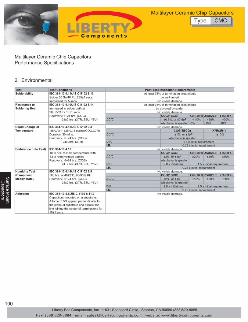
100
Surface M
ountS
urface Mount
Capacitors
Capacitors
Sur
face
Mou
ntC
apac
itors
Multilayer Ceramic Chip CapacitorsPerformance Specifications
2. Environmental
Test Test ConditionsSolderability IEC 384-10 4.11/JIS C 5102 8.13
Solder 60 Sn/40 Pb, 235±1 secs.Immersed for 5 secs.
Resistance to IEC 384-10 4.10/JIS C 5102 8.14Soldering Heat Immersed in solder bath at
260±5ºC for 10±1 secs. Recovery: 6~24 hrs. (COG) COG(1BCG) X7R(2R1) Z5U(2E6) Y5U(2F4) 24±2 hrs. (X7R, Z5U, Y5V) ΔC/C ±0.5%, or ±0.5pF + 10% +20% +20%
whichever is greater -5% -10% -10%Rapid Change of IEC 384-10 4.12/JIS C 5102 9.3Temperature -55ºC to + 125ºC, 5 cycles(COG,X7R)
Duration: 30 mins. ΔC/CRecovery: 6~24 hrs. (COG) 24±2hrs. (X7R) D.F.
I.R.Endurance (Life Test) IEC 384-10 4.15
1000 hrs. at max. temperature with COG(1BCG) X7R(2R1) Z5U(2E6) Y5U(2F4)1.5 x rated voltage applied ΔC/C ±2%, or ±1pF ±20% ±20% ±30%Recovery: 6~24 hrs. (COG) whichever is greater 24±2 hrs. (X7R, Z5U, Y5V) D.F. 2.0 x initial req.
I.R.Humidity Test IEC 384-10 4.14/JIS C 5102 9.5(Damp heat, 500 hrs. at 40±2ºC, 90-95% RH COG(1BCG) X7R(2R1) Z5U(2E6) Y5U(2F4)steady state) Recovery: 6~24 hrs. (COG) ΔC/C ±2%, or ±1pF ±10% ±20% ±30%
24±2 hrs. (X7R, Z5U, Y5V) whichever is greater D.F. 2.0 x initial req.I.R.
Adhesion IEC 384-10 4.8/JIS C 5102 8.11.2Capacitors mounted on a substrate.A force of 5N applied perpendicular tothe plane of substrate and parallel theline joining the center of terminations for 10±1 secs.
No visible damage.
No visible damage.
No visible damage.
No visible damage.
No visible damage.
At least 75% of termination area shouldbe well tinned.
No visible damage.At least 75% of termination area should
be covered by solder.
1.5 x initial requirement 0.25 x initial requirement
Post-Test Inspection Requirements
X7R(2R1) ±10%
COG(1BCG) ±1%, or ±1pF
whichever is greater 1.5 x initial requirement 0.25 x initial requirement
1.5 x initial requirement 0.25 x initial requirement
Type CMCMultilayer Ceramic Chip Capacitors
Liberty Bell Components, Inc. 11631 Seaboard Circle, Stanton, CA 90680 (888)820-8885Fax: (888)820-8884 email: [email protected] website: www.libertycomponents.com

101
Surface M
ountC
apacitors
Sur
face
Mou
ntS
urfa
ce M
ount
Cap
acito
rsC
apac
itors
-0.6
-0.3
0
0.3
0.6
-75 -50 -25 0 25 50 75 100 125
Temperature (°C)
Δ C
(%
)
0
0.05
0.1
0.15
-75 -50 -25 0 25 50 75 100 125
Temperature (°C)
D.F
. (%
)
-3-2-10123
0 50 100 150 200 250
DC Voltage (V)
Δ C
(%
)
-3-2-10123
0 4 8 12 16 20
AC Voltage (Vrms)
Δ C
(%
)
-3-2-10123
0.1 1 10 100 1000 10000
Time (hours)
Δ C
(%
)
-80
-60
-40
-20
0
20
-75 -50 -25 0 25 50 75 100 125
Temperature (°C)
Δ C
(%
)
0
1
2
3
4
5
-75 -50 -25 0 25 50 75 100 125
Temperature (°C)D
.F.
(%)
-80
-60
-40
-20
0
20
0 10 20 30 40 50
DC Voltage (V)
Δ C
(%
)
0
10
20
30
40
0 5 10 15 20 25
AC Voltage (Vrms)
Δ C
(%
)
-30
-20
-10
0
0.1 1 10 100 1000 10000
Time (hours)
Δ C
(%
)
-3-2-10123
0.01 0.1 1 10 100 1000
Frequency (MHz)
Δ C
(%
)
-30
-20
-10
0
0.001 0.01 0.1 1 10 100 1000
Frequency (MHz)
Δ C
(%
)
COG(1B) X7R (2R1), Z5U (2E6), Y5V(2F4)
X7R
Z5U
Y5V
X7RZ5U
Y5V
X7R
Z5UY5V
X7R
Z5U & Y5V
X7R
Z5U & Y5V
X7R
Y5V
Z5U
Type CMCMultilayer Ceramic Chip Capacitors
Liberty Bell Components, Inc. 11631 Seaboard Circle, Stanton, CA 90680 (888)820-8885Fax: (888)820-8884 email: [email protected] website: www.libertycomponents.com
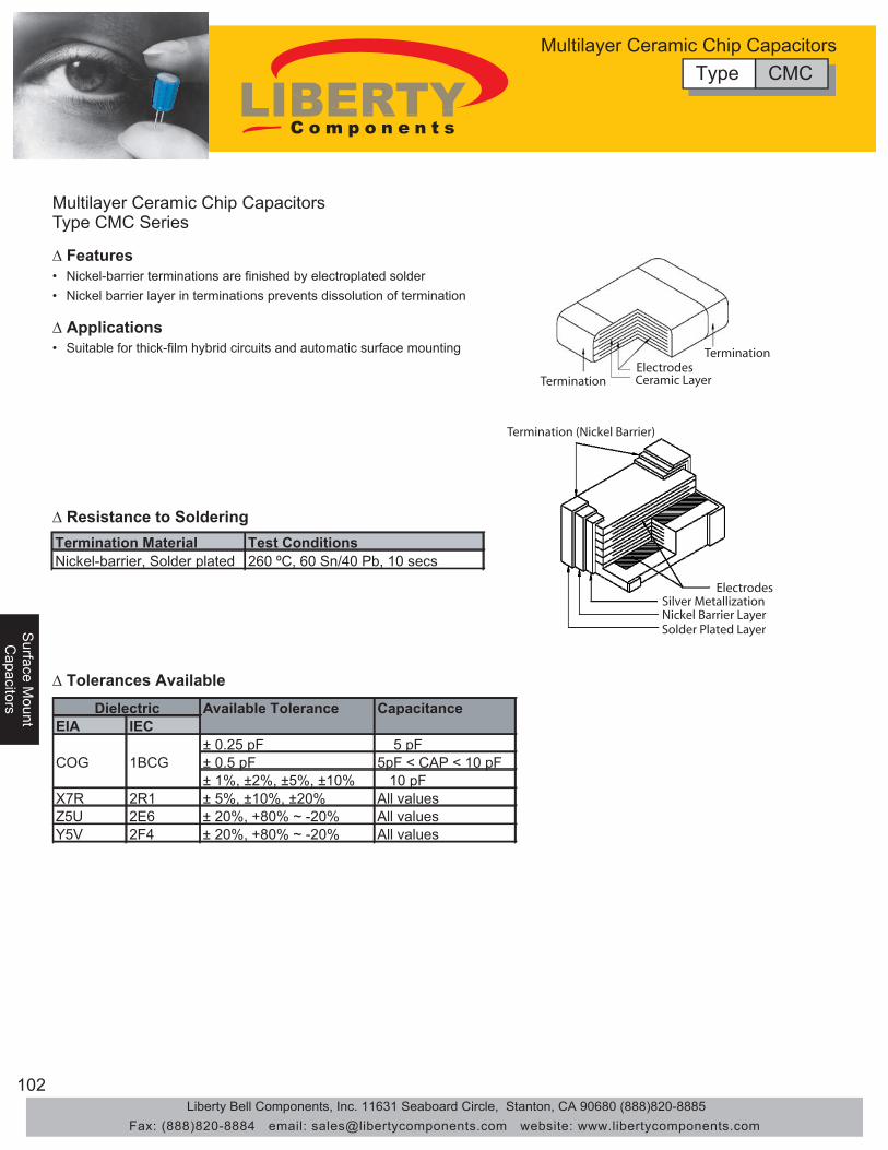
102
Surface M
ountS
urface Mount
Capacitors
Capacitors
Sur
face
Mou
ntC
apac
itors
Multilayer Ceramic Chip CapacitorsType CMC Series
• Nickel-barrier terminations are finished by electroplated solder
• Suitable for thick-film hybrid circuits and automatic surface mounting
• Nickel barrier layer in terminations prevents dissolution of termination
TerminationElectrodesCeramic Layer
Termination
ElectrodesSilver MetallizationNickel Barrier LayerSolder Plated Layer
Termination (Nickel Barrier)
Termination Material Test ConditionsNickel-barrier, Solder plated 260 ºC, 60 Sn/40 Pb, 10 secs
Available Tolerance CapacitanceEIA IEC
± 0.25 pF 5 pFCOG 1BCG ± 0.5 pF 5pF < CAP < 10 pF
± 1%, ±2%, ±5%, ±10% 10 pFX7R 2R1 ± 5%, ±10%, ±20% All valuesZ5U 2E6 ± 20%, +80% ~ -20% All valuesY5V 2F4 ± 20%, +80% ~ -20% All values
Dielectric
∆ Features
∆ Applications
∆ Resistance to Soldering
∆ Tolerances Available
Type CMCMultilayer Ceramic Chip Capacitors
Liberty Bell Components, Inc. 11631 Seaboard Circle, Stanton, CA 90680 (888)820-8885Fax: (888)820-8884 email: [email protected] website: www.libertycomponents.com
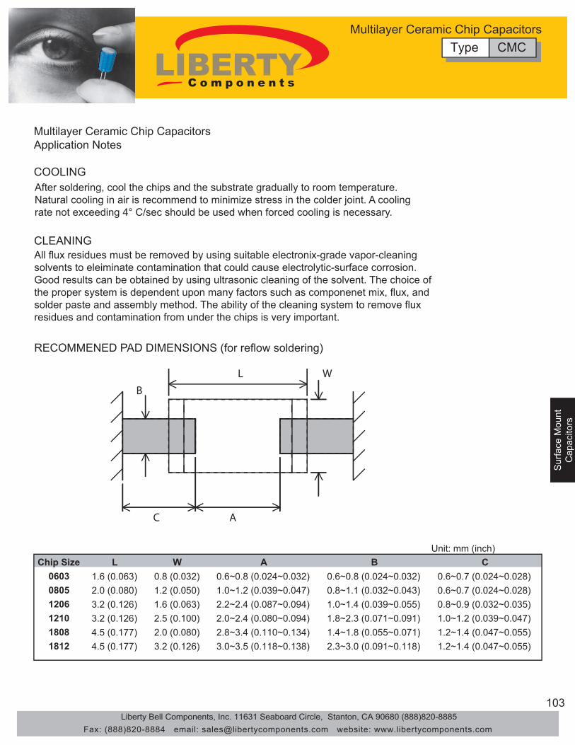
103
Surface M
ountC
apacitors
Sur
face
Mou
ntS
urfa
ce M
ount
Cap
acito
rsC
apac
itors
Multilayer Ceramic Chip CapacitorsApplication Notes
COOLINGAfter soldering, cool the chips and the substrate gradually to room temperature. Natural cooling in air is recommend to minimize stress in the colder joint. A coolingrate not exceeding 4° C/sec should be used when forced cooling is necessary.
CLEANINGAll flux residues must be removed by using suitable electronix-grade vapor-cleaningsolvents to eleiminate contamination that could cause electrolytic-surface corrosion.Good results can be obtained by using ultrasonic cleaning of the solvent. The choice ofthe proper system is dependent upon many factors such as componenet mix, flux, andsolder paste and assembly method. The ability of the cleaning system to remove fluxresidues and contamination from under the chips is very important.
RECOMMENED PAD DIMENSIONS (for reflow soldering)
L W
B
C A
Unit: mm (inch)Chip Size L W A B C
0603 1.6 (0.063) 0.8 (0.032) 0.6~0.8 (0.024~0.032) 0.6~0.8 (0.024~0.032) 0.6~0.7 (0.024~0.028)0805 2.0 (0.080) 1.2 (0.050) 1.0~1.2 (0.039~0.047) 0.8~1.1 (0.032~0.043) 0.6~0.7 (0.024~0.028)1206 3.2 (0.126) 1.6 (0.063) 2.2~2.4 (0.087~0.094) 1.0~1.4 (0.039~0.055) 0.8~0.9 (0.032~0.035)1210 3.2 (0.126) 2.5 (0.100) 2.0~2.4 (0.080~0.094) 1.8~2.3 (0.071~0.091) 1.0~1.2 (0.039~0.047)1808 4.5 (0.177) 2.0 (0.080) 2.8~3.4 (0.110~0.134) 1.4~1.8 (0.055~0.071) 1.2~1.4 (0.047~0.055)1812 4.5 (0.177) 3.2 (0.126) 3.0~3.5 (0.118~0.138) 2.3~3.0 (0.091~0.118) 1.2~1.4 (0.047~0.055)
Type CMCMultilayer Ceramic Chip Capacitors
Liberty Bell Components, Inc. 11631 Seaboard Circle, Stanton, CA 90680 (888)820-8885Fax: (888)820-8884 email: [email protected] website: www.libertycomponents.com
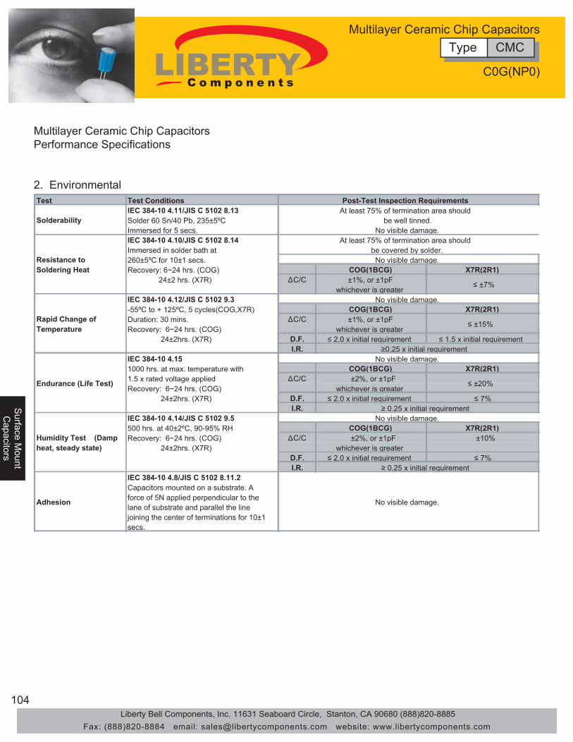
104
Surface M
ountS
urface Mount
Capacitors
Capacitors
Sur
face
Mou
ntC
apac
itors
Multilayer Ceramic Chip CapacitorsPerformance Specifications
2. EnvironmentalTest Test Conditions
IEC 384-10 4.11/JIS C 5102 8.13Solder 60 Sn/40 Pb, 235±5ºCImmersed for 5 secs.IEC 384-10 4.10/JIS C 5102 8.14Immersed in solder bath at260±5ºC for 10±1 secs. Recovery: 6~24 hrs. (COG) COG(1BCG) X7R(2R1) 24±2 hrs. (X7R) ΔC/C ±1%, or ±1pF
whichever is greaterIEC 384-10 4.12/JIS C 5102 9.3-55ºC to + 125ºC, 5 cycles(COG,X7R) COG(1BCG) X7R(2R1)Duration: 30 mins. ΔC/C ±1%, or ±1pFRecovery: 6~24 hrs. (COG) whichever is greater 24±2hrs. (X7R) D.F. ≤ 2.0 x initial requirement ≤ 1.5 x initial requirement
I.R.IEC 384-10 4.151000 hrs. at max. temperature with COG(1BCG) X7R(2R1)1.5 x rated voltage applied ΔC/C ±2%, or ±1pFRecovery: 6~24 hrs. (COG) whichever is greater 24±2hrs. (X7R) D.F. ≤ 2.0 x initial requirement ≤ 7%
I.R.IEC 384-10 4.14/JIS C 5102 9.5500 hrs. at 40±2ºC, 90-95% RH COG(1BCG) X7R(2R1)Recovery: 6~24 hrs. (COG) ΔC/C ±2%, or ±1pF ±10% 24±2hrs. (X7R) whichever is greater
D.F. ≤ 2.0 x initial requirement ≤ 7%I.R.
IEC 384-10 4.8/JIS C 5102 8.11.2
No visible damage.
≤ ±7%
≤ ±15%
≤ ±20%
≥ 0.25 x initial requirement
≥ 0.25 x initial requirement
≥ 0.25 x initial requirement
No visible damage.
be covered by solder.No visible damage.
No visible damage.
No visible damage.
Post-Test Inspection RequirementsAt least 75% of termination area should
be well tinned.No visible damage.
Solderability
Resistance to Soldering Heat
Rapid Change of Temperature
Endurance (Life Test)
At least 75% of termination area should
Humidity Test (Damp heat, steady state)
Adhesion
Capacitors mounted on a substrate. A force of 5N applied perpendicular to the lane of substrate and parallel the line joining the center of terminations for 10±1 secs.
Type CMCMultilayer Ceramic Chip Capacitors
C0G(NP0)
Liberty Bell Components, Inc. 11631 Seaboard Circle, Stanton, CA 90680 (888)820-8885Fax: (888)820-8884 email: [email protected] website: www.libertycomponents.com

105
Surface M
ountC
apacitors
Sur
face
Mou
ntS
urfa
ce M
ount
Cap
acito
rsC
apac
itors
Multilayer Ceramic Chip CapacitorsType CMC SeriesCOG (NPO)EIA/IEC Dielectric Code: COG/1BCG
0805 1206 1210 18122.00±0.20(0.080±0.008) 3.20±0.20(0.126±0.008) 3.20±0.30(0.126±0.012) 4.50±0.30(0.177±0.012)1.20±0.20(0.050±0.008) 1.60±0.20(0.063±0.008) 2.50±0.30(0.100±0.012) 3.20±0.30(0.126±0.012)0.50±0.20(0.020±0.008) 0.50±0.20(0.020±0.008) 0.50±0.20(0.020±0.008) 0.64±0.38(0.025±0.015)
25 50 50 50 50 50Cap 0.47(pf) 1.0
1.21.51.82.22.73.33.94.75.66.88.2101215182227333947566882100120150180220270330390470560680820100012001500180022002700330039004700560068008200
Cap. .010(μF) .012
.015
.018
.022
1.60±0.15(0.063±0.006)0.08±0.15(0.032±0.06)0.40±0.20(0.16±0.008)
COG/1BCGSize
EIA/IEC Dielectric Code0603
W.V.D.C.(E) Termination mm(in)
(W) Width mm(in)(L) Length mm(in)
Type CMCMultilayer Ceramic Chip Capacitors
C0G(NP0)
Liberty Bell Components, Inc. 11631 Seaboard Circle, Stanton, CA 90680 (888)820-8885Fax: (888)820-8884 email: [email protected] website: www.libertycomponents.com

106
Surface M
ountS
urface Mount
Capacitors
Capacitors
Sur
face
Mou
ntC
apac
itors
Multilayer Ceramic Chip CapacitorsType CMC - High Voltage SeriesCOG (NPO)EIA/IEC Dielectric Code: COG/1BCG
0603 0805 1206 1210 1812 0805 1206 1210 1812 0805 1206 1210 1808 1812Cap. 10(pF) 12
15182227333947566882100120150180220270330390470560680820100012001500180022002700330039004700560068008200
Cap. .010(pF) .012
.015
500VCOG / 1BCGEIA/IEC Dielectric Code
SizeW.V.D.C. 100V 250V
Type CMCMultilayer Ceramic Chip Capacitors
C0G(NP0)
Liberty Bell Components, Inc. 11631 Seaboard Circle, Stanton, CA 90680 (888)820-8885Fax: (888)820-8884 email: [email protected] website: www.libertycomponents.com
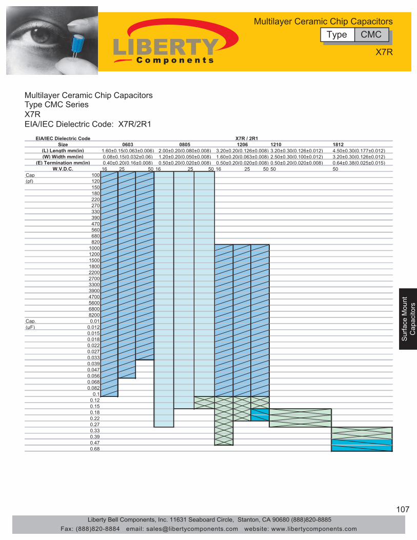
107
Surface M
ountC
apacitors
Sur
face
Mou
ntS
urfa
ce M
ount
Cap
acito
rsC
apac
itors
Multilayer Ceramic Chip CapacitorsType CMC SeriesX7REIA/IEC Dielectric Code: X7R/2R1
1210 18123.20±0.30(0.126±0.012) 4.50±0.30(0.177±0.012)2.50±0.30(0.100±0.012) 3.20±0.30(0.126±0.012)0.50±0.20(0.020±0.008) 0.64±0.38(0.025±0.015)
16 25 50 16 25 50 16 25 50 50 50Cap 100(pf) 120
150180220270330390470560680820
100012001500180022002700330039004700560068008200
Cap. 0.01(μF) 0.012
0.0150.0180.0220.0270.0330.0390.0470.0560.0680.082
0.10.120.150.180.220.270.330.390.470.68
2.00±0.20(0.080±0.008)1.20±0.20(0.050±0.008)0.50±0.20(0.020±0.008)
12063.20±0.20(0.126±0.008)1.60±0.20(0.063±0.008)0.50±0.20(0.020±0.008)(E) Termination mm(in)
W.V.D.C.
06031.60±0.15(0.063±0.006)0.08±0.15(0.032±0.06)0.40±0.20(0.16±0.008)
(L) Length mm(in)(W) Width mm(in)
X7R / 2R1EIA/IEC Dielectric CodeSize 0805
Type CMCMultilayer Ceramic Chip Capacitors
X7R
Liberty Bell Components, Inc. 11631 Seaboard Circle, Stanton, CA 90680 (888)820-8885Fax: (888)820-8884 email: [email protected] website: www.libertycomponents.com

108
Surface M
ountS
urface Mount
Capacitors
Capacitors
Sur
face
Mou
ntC
apac
itors
Multilayer Ceramic Chip CapacitorsType CMC - High Voltage SeriesX7REIA/IEC Dielectric Code: X7R/2R1
0603 0805 1206 1210 1812 0805 1206 1210 1812 0805 1206 1210 1808 1812Cap. 100(pF) 120
150180220270330390470560680820100012001500180022002700330039004700560068008200
Cap. .010(pF) .012
.015
.018
.022
.027
.033
.039
.047
.056
.068
.082
.10
.12
.15
.18
.22
.27
.33
.47
.56
.68
500VX7R / 2R1EIA/IEC Dielectric Code
SizeW.V.D.C. 100V 250V
Type CMCMultilayer Ceramic Chip Capacitors
X7R
Liberty Bell Components, Inc. 11631 Seaboard Circle, Stanton, CA 90680 (888)820-8885Fax: (888)820-8884 email: [email protected] website: www.libertycomponents.com

109
Surface M
ountC
apacitors
Sur
face
Mou
ntS
urfa
ce M
ount
Cap
acito
rsC
apac
itors
Multilayer Ceramic Chip CapacitorsType CMC SeriesY5VEIA/IEC Dielectric Code: Y5V/2F4
W.V.D.C. 10 16 25 50 16 25 50 16 25 50 25 50 25 50Cap. 0.01(μF) 0.012
0.0150.0180.0220.0270.0330.0390.0470.0560.0680.082
0.10.120.150.180.220.270.330.390.470.560.680.82
11.21.51.82.22.73.3
0.08±0.15(0.032±0.06)0.40±0.20(0.16±0.008)
0603X7R / 2R1
0.50±0.20(0.020±0.008) 0.64±0.38(0.025±0.015)
12063.20±0.20(0.126±0.008)1.60±0.20(0.063±0.008)0.50±0.20(0.020±0.008)(E) Termination mm(in) 0.50±0.20(0.020±0.008)
3.20±0.30(0.126±0.012) 4.50±0.30(0.177±0.012)(W) Width mm(in) 2.50±0.30(0.100±0.012) 3.20±0.30(0.126±0.012)1.20±0.20(0.050±0.008)
2.00±0.20(0.080±0.008)(L) Length mm(in) 1.60±0.15(0.063±0.006)
EIA/IEC Dielectric CodeSize 1210 18120805
Type CMCMultilayer Ceramic Chip Capacitors
Y5V
Liberty Bell Components, Inc. 11631 Seaboard Circle, Stanton, CA 90680 (888)820-8885Fax: (888)820-8884 email: [email protected] website: www.libertycomponents.com

110
Surface M
ountS
urface Mount
Capacitors
Capacitors
Sur
face
Mou
ntC
apac
itors
Multilayer Ceramic Chip CapacitorsType CMC SeriesZ5UEIA/IEC Dielectric Code: Z5U/2E6
W.V.D.C. 25 50 25 50 25 50 25 50 25 50Cap. 2700(pF) 3300
39004700560068008200
Cap. 0.01(μF) 0.012
0.0150.0180.0220.0270.0330.0390.0470.0560.0680.082
0.10.120.150.180.220.270.330.390.470.560.680.82
11.21.51.8
4.50±0.30(0.177±0.012)3.20±0.30(0.126±0.012)0.64±0.38(0.025±0.015)
12103.20±0.30(0.126±0.012)2.50±0.30(0.100±0.012)0.50±0.20(0.020±0.008)(E) Termination mm(in) 0.50±0.20(0.020±0.008)0.50±0.20(0.020±0.008)0.40±0.20(0.16±0.008)
(W) Width mm(in) 1.60±0.20(0.063±0.008)1.20±0.20(0.050±0.008)0.08±0.15(0.032±0.06)(L) Length mm(in) 3.20±0.20(0.126±0.008)2.00±0.20(0.080±0.008)1.60±0.15(0.063±0.006)
EIA/IEC Dielectric CodeSize 0603 12060805
X7R / 2R11812
Type CMCMultilayer Ceramic Chip Capacitors
Z5U
Liberty Bell Components, Inc. 11631 Seaboard Circle, Stanton, CA 90680 (888)820-8885Fax: (888)820-8884 email: [email protected] website: www.libertycomponents.com

111
Surface M
ountC
apacitors
Sur
face
Mou
ntS
urfa
ce M
ount
Cap
acito
rsC
apac
itors
Multilayer Ceramic Chip CapacitorsType CMC - High Voltage SeriesZ5UEIA/IEC Dielectric Code: Z5U/2E6
250V0805 1206 1210 1812 1812
Cap. .033(pF) .039
.047
.056
.068
.082
.10
.12
.15
.18
.22
.27
.33
.39
.47
.56
.68
.821.01.2.15
Z5U / 2E6EIA/IEC Dielectric Code
SizeW.V.D.C. 100V
Type CMCMultilayer Ceramic Chip Capacitors
Z5U
Liberty Bell Components, Inc. 11631 Seaboard Circle, Stanton, CA 90680 (888)820-8885Fax: (888)820-8884 email: [email protected] website: www.libertycomponents.com

112
Surface M
ountS
urface Mount
Capacitors
Capacitors
Sur
face
Mou
ntC
apac
itors
High Voltage Ceramic Chip Capacitors Type CFK
∆ Features • Surface Mount • Rated Voltage: 250 VAC, 5000VDC • Chip Size: 1808, 1812, 2211
∆ Applications• Suitable for wave and reflow soldering
∆ DimensionsSize 1808 1812 2211
mm 4.60±0.30 0.30± 4.60 4.60±0.30(in) (0.181±0.12) (0.12±0.181) (0.181±0.12)mm 2.00±0.20 0.20±3.20 3.20±0.30(in) (0.080±0.008) (0.008±0.126) (0.126±0.012)mm 0.64±0.38 0.38±0.64 0.64±0.38(in) (0.025±0.015) (0.015±0.025) (0.025±0.015)mm 2.20 2.70 2.70(in) (0.087) (0.106) (0.106)
(L) Length
(W) Width
(E) Termination
(T) Thickness
∆ SpecificationsSize Length / Width Volt Capacitance
2211 L: 5.70±0.040mm (0.224±0.016)W: 2.80±0.030mm (0.110±0.012) 250 130pF-2200pF
X1Y1 - TUV/UL
1812 L: 4.60±0.030mm (0.181±0.012)W: 3.20±0.030mm (0.126±0.012) 250 150pF-1000pF
X1Y2 - TUV/UL
1808 L: 4.60±0.030mm (0.181±0.012)W: 2.00±0.020mm (0.080±0.008) 250 100pF-1000pF
X1Y2 - TUV/UL
250 5.0pF-100pFX1Y2 - SEMKO
250 3pF-150pFX1Y2 - TUV/UL
NPO 1808 L: 4.60±0.030mm (0.181±0.012)W: 2.00±0.020mm (0.080±0.008)
X7R
Type CFKHigh Voltage Ceramic Chip Capacitors
• Use in mobile, facsimile, telephone and other telecom electronic equipment where lightning surges occur.
Liberty Bell Components, Inc. 11631 Seaboard Circle, Stanton, CA 90680 (888)820-8885Fax: (888)820-8884 email: [email protected] website: www.libertycomponents.com

113
Surface M
ountC
apacitors
Sur
face
Mou
ntS
urfa
ce M
ount
Cap
acito
rsC
apac
itors
High Voltage Ceramic Chip Capacitors Type CFK
Test Test Conditions Post-Test Inspection RequirementsClass I:∆C: 0±30ppm/°CClass II:∆C: ≤ ±15%
Class I:1MHz, 1VrmsClass II:1KHz, 1VrmsClass I: Class I:1MHz, 1Vrms ≤ 0.1%Class II: Class II:1KHz, 1Vrms ≤ 2.5%Class I: Class I:After 60 sec charging at 500V (DC)25°C, 55% RH max.
≥100GΩ or ≥1000MΩ.μFWhichever is smaller
Class II: Class II:After 60 sec charging at 500V (DC)25°C, 55% RH max.
≥10GΩ or ≥100MΩ.μFWhichever is smaller
Impulse Voltage Each Individual Capacitor shall be subjected to a 5.0KV(X1Y2) impulse
No breakdown or failure
Withstanding Voltage Test 1.5KV AC for 60 sec No breakdown or failure
Dissipation Factor (D.F.) and Tangent of
Loss Angle (tanδ)
Insulation Resistance (I.R.)
Operating temp. range: -55 to +125°CTemperature Coefficients
Capacitance Capacitance is within specified tolerance
∆ Electrical
Type CFKHigh Voltage Ceramic Chip Capacitors
Liberty Bell Components, Inc. 11631 Seaboard Circle, Stanton, CA 90680 (888)820-8885Fax: (888)820-8884 email: [email protected] website: www.libertycomponents.com

114
Surface M
ountS
urface Mount
Capacitors
Capacitors
Sur
face
Mou
ntC
apac
itors
High Voltage Ceramic Chip Capacitors Type CFK
∆ Environmental Test Test Conditions
∆C/C: ≤±2.5% or 0.25pF whichever is larger I.R.: More than 10GΩ D.F.: ≤2.5% ∆C/C: ≤10% I.R.: More than 1GΩ D.F.: ≤2.5%
∆C/C: ≤±5% I.R.: More than 1GΩ D.F.: ≤0.25% ∆C/C: ≤10% I.R.: ≥ 1GΩ or 50MΩ·μFwhichever is smaller D.F.: ≤2.5%
∆C/C: ≤±5% or 0.5pF whichever is larger I.R.: More than 10GΩ D.F.: ≤2.5% ∆C/C: ≤10% I.R.: ≥ 1GΩ or 50MΩ·μFwhichever is smaller D.F.: ≤5%
Adhesion Strength of Termination
Capacitors mounted on a substrate. A force of 5N applied perpendicular to the place of substrate and parallel the line joining the center of terminations for 10±1 sec.
Resistance to Flexure Stress
Capacitors mounted on a substrate. The board shall then be bent by 1mm at a rate of 1mm/sec.
Active Flammability The capacitor is applied Ur(250VAC). Then each sample shall be subjected to 20 discharges from a tank capacitor, charge to a voltage that, when discharged, places Ui 2500V for X2Y3, Ui 5000V for X1Y2 across the capacitor under test. The interval between successive discharges shall be 5 sec.
No Visible Damage
No Visible Damage Change in capacitance is less than 10%
The cheese cloth shall not burn with a flame.
No Visible Damage Class I:
Class II:
Humidity Test (Damp heat, steady state)
Preconditioning 500+24-0 hr. at 40 ± 2°C,
90~95% relative humidity. The capacitor with rated voltage (250VAC) applied. Recovery: 12 ± 1hr.
Post-Test Inspection Requirements
At least 75% of termination area should be well tinned
Immersed in Solder bath at 245 ± 5°C for 5 ± 0.5 sec.
No Visible Damage
No Visible Damage Class I:
No Visible Damage Class I:
Class II:
Endurance(Life Test)
Class II:
Resistance to Soldering Heat
Immersed in Solder bath at 245 ± 5°C for 5 ± 0.5 sec. Recovery: 12 ± 1hr.
Preconditioning 1000+48-0 hr. at upper
category temperature applied at: 1.25UR (X1,X2) or 1.7UR (Y2,Y3) Once every hour the voltage shall be increased to 1000Vrms for 0.1 sec. Recovery: 12 ± 1hr.
Solderability
Type CFKHigh Voltage Ceramic Chip Capacitors
Liberty Bell Components, Inc. 11631 Seaboard Circle, Stanton, CA 90680 (888)820-8885Fax: (888)820-8884 email: [email protected] website: www.libertycomponents.com
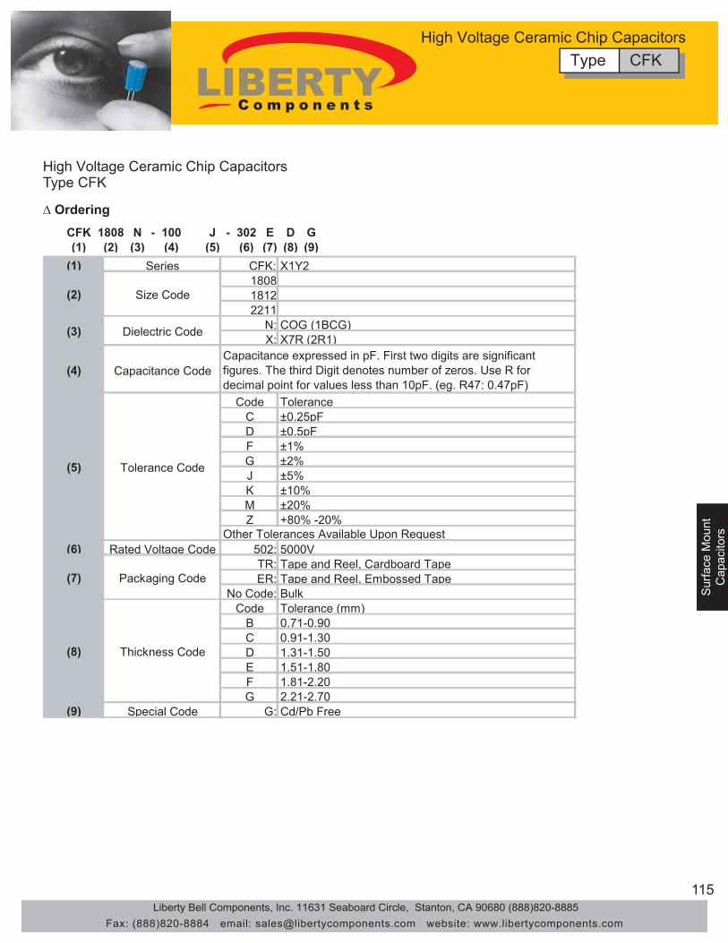
115
Surface M
ountC
apacitors
Sur
face
Mou
ntS
urfa
ce M
ount
Cap
acito
rsC
apac
itors
High Voltage Ceramic Chip Capacitors Type CFK
∆ Ordering CFK 1808 N - 100 J - 302 E D G (1) (2) (3) (4) (5) (6) (7) (8) (9)
(1) Series CFK: X1Y21808 1812 2211
N: COG (1BCG) X: X7R (2R1)
(4) Capacitance Code
Code Tolerance C ±0.25pF D ±0.5pF F ±1% G ±2% J ±5% K ±10% M ±20% Z +80% -20%
(6) Rated Voltage Code 502: 5000V TR: Tape and Reel, Cardboard Tape ER: Tape and Reel, Embossed Tape
No Code: Bulk Code Tolerance (mm)
B 0.71-0.90 C 0.91-1.30 D 1.31-1.50 E 1.51-1.80 F 1.81-2.20 G 2.21-2.70
(9) Special Code G: Cd/Pb Free
(8) Thickness Code
(7) Packaging Code
Capacitance expressed in pF. First two digits are significant figures. The third Digit denotes number of zeros. Use R for decimal point for values less than 10pF. (eg. R47: 0.47pF)
Other Tolerances Available Upon Request
(2) Size Code
(3) Dielectric Code
(5) Tolerance Code
Type CFKHigh Voltage Ceramic Chip Capacitors
Liberty Bell Components, Inc. 11631 Seaboard Circle, Stanton, CA 90680 (888)820-8885Fax: (888)820-8884 email: [email protected] website: www.libertycomponents.com

116
Surface M
ountS
urface Mount
Capacitors
Capacitors
Sur
face
Mou
ntC
apac
itors
High Voltage Ceramic Chip Capacitors Type CFH
∆ Features • Surface Mount • Rated Voltage: 250 VAC, 3000VDC • Chip Size: 1808, 1812
∆ Applications • Suitable for wave and reflow soldering • Use in mobile, facsimile, telephone and other telecom electronic equipment where lightning surges occur.
∆ Dimensions
Size 1808 1812mm 4.60±0.30 0.30± 4.60(in) (0.181±0.12) (0.12±0.181)mm 2.00±0.20 0.20±3.20(in) (0.080±0.008) (0.008±0.126)mm 0.64±0.38 0.64±0.38(in) (0.025±0.015) (0.015±0.025)mm 2.20 2.70(in) (0.087) (0.106)
(L) Length
(W) Width
(E) Termination
(T) Thickness
Size Length / Width Volt Capacitance
1812L: 4.60±0.030mm (0.181±0.012)W: 3.20±0.030mm (0.126±0.012)
250300pF-2700pFX2Y3 - TUV/UL
250150pF-1000pFX2Y3 - SEMKO
250150pF-1800pFX2Y3 - TUV/UL
2505.0pF-220pF
X2Y3 - SEMKO
2503pF-1000pF
X2Y3 - TUV/UL
L: 4.60±0.030mm (0.181±0.012)W: 2.00±0.020mm (0.080±0.008)
1808X7R
NPO 1808L: 4.60±0.030mm (0.181±0.012)W: 2.00±0.020mm (0.080±0.008)
∆ Specifications
Type CFHHigh Voltage Ceramic Chip Capacitors
Liberty Bell Components, Inc. 11631 Seaboard Circle, Stanton, CA 90680 (888)820-8885Fax: (888)820-8884 email: [email protected] website: www.libertycomponents.com

117
Surface M
ountC
apacitors
Sur
face
Mou
ntS
urfa
ce M
ount
Cap
acito
rsC
apac
itors
High Voltage Ceramic Chip Capacitors Type CFH
∆ Electrical
Test Test Conditions Post-Test Inspection RequirementsClass I:∆C: 0±30ppm/°CClass II:∆C: ≤ ±15%
Class I:1MHz, 1VrmsClass II:1KHz, 1VrmsClass I: Class I:1MHz, 1Vrms ≤ 0.1%Class II: Class II:1KHz, 1Vrms ≤ 2.5%Class I: Class I:After 60 sec charging at 500V (DC)25°C, 55% RH max.
≥100GΩ or ≥1000MΩ.μFWhichever is smaller
Class II: Class II:After 60 sec charging at 500V (DC)25°C, 55% RH max.
≥10GΩ or ≥100MΩ.μFWhichever is smaller
Impulse Voltage Each Individual Capacitor shall be subjected to a 2.5KV(X2/Y3) impulse
No breakdown or failure
Withstanding Voltage Test 1.5KV AC for 60 sec No breakdown or failure
Capacitance is within specified tolerance
Dissipation Factor (D.F.) and Tangent of
Loss Angle (tanδ)
Insulation Resistance (I.R.)
Operating temp. range: -55 to +125°CTemperature Coefficients
Capacitance
Type CFHHigh Voltage Ceramic Chip Capacitors
Liberty Bell Components, Inc. 11631 Seaboard Circle, Stanton, CA 90680 (888)820-8885Fax: (888)820-8884 email: [email protected] website: www.libertycomponents.com
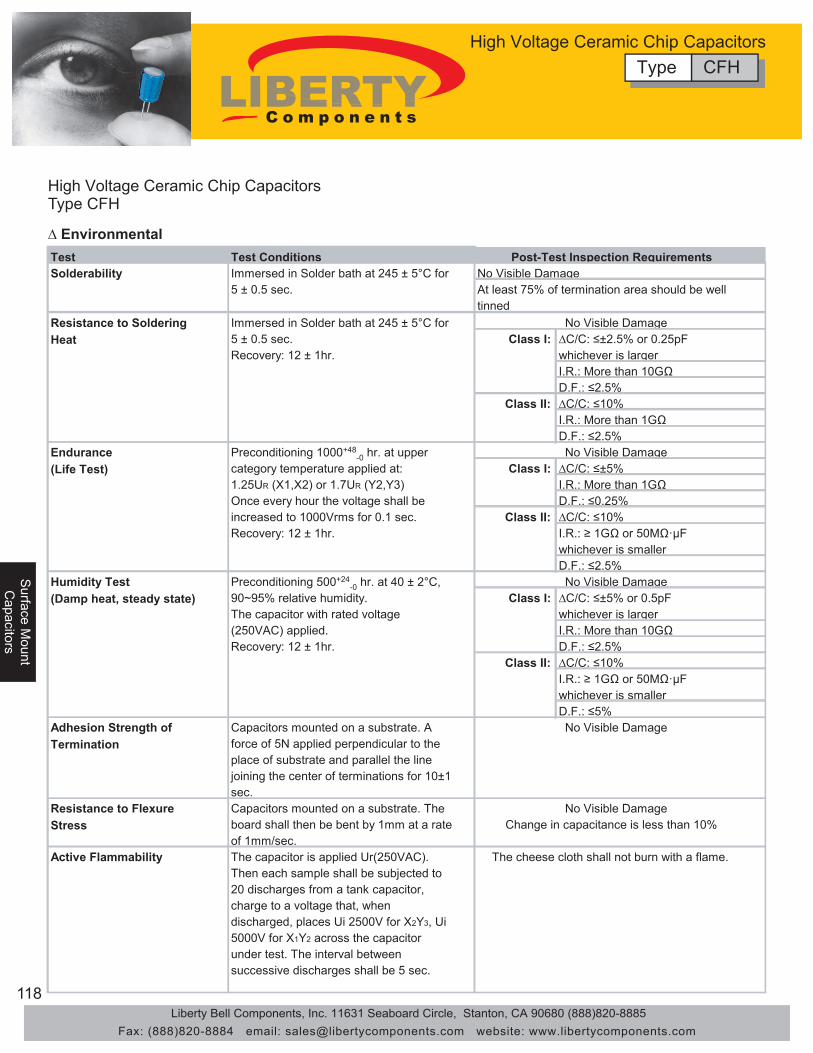
118
Surface M
ountS
urface Mount
Capacitors
Capacitors
Sur
face
Mou
ntC
apac
itors
High Voltage Ceramic Chip Capacitors Type CFH
∆ Environmental Test Test Conditions
∆C/C: ≤±2.5% or 0.25pF whichever is larger I.R.: More than 10GΩ D.F.: ≤2.5% ∆C/C: ≤10% I.R.: More than 1GΩ D.F.: ≤2.5%
∆C/C: ≤±5% I.R.: More than 1GΩ D.F.: ≤0.25% ∆C/C: ≤10% I.R.: ≥ 1GΩ or 50MΩ·μFwhichever is smaller D.F.: ≤2.5%
∆C/C: ≤±5% or 0.5pF whichever is larger I.R.: More than 10GΩ D.F.: ≤2.5% ∆C/C: ≤10% I.R.: ≥ 1GΩ or 50MΩ·μFwhichever is smaller D.F.: ≤5%
Adhesion Strength of Termination
Capacitors mounted on a substrate. A force of 5N applied perpendicular to the place of substrate and parallel the line joining the center of terminations for 10±1 sec.
Resistance to Flexure Stress
Capacitors mounted on a substrate. The board shall then be bent by 1mm at a rate of 1mm/sec.
Active Flammability The capacitor is applied Ur(250VAC). Then each sample shall be subjected to 20 discharges from a tank capacitor, charge to a voltage that, when discharged, places Ui 2500V for X2Y3, Ui 5000V for X1Y2 across the capacitor under test. The interval between successive discharges shall be 5 sec.
No Visible Damage
No Visible Damage Change in capacitance is less than 10%
The cheese cloth shall not burn with a flame.
No Visible Damage Class I:
Class II:
Humidity Test (Damp heat, steady state)
Preconditioning 500+24-0 hr. at 40 ± 2°C,
90~95% relative humidity. The capacitor with rated voltage (250VAC) applied. Recovery: 12 ± 1hr.
Post-Test Inspection Requirements
At least 75% of termination area should be well tinned
Immersed in Solder bath at 245 ± 5°C for 5 ± 0.5 sec.
No Visible Damage
No Visible Damage Class I:
No Visible Damage Class I:
Class II:
Endurance(Life Test)
Class II:
Resistance to Soldering Heat
Immersed in Solder bath at 245 ± 5°C for 5 ± 0.5 sec. Recovery: 12 ± 1hr.
Preconditioning 1000+48-0 hr. at upper
category temperature applied at: 1.25UR (X1,X2) or 1.7UR (Y2,Y3) Once every hour the voltage shall be increased to 1000Vrms for 0.1 sec. Recovery: 12 ± 1hr.
Solderability
Type CFHHigh Voltage Ceramic Chip Capacitors
Liberty Bell Components, Inc. 11631 Seaboard Circle, Stanton, CA 90680 (888)820-8885Fax: (888)820-8884 email: [email protected] website: www.libertycomponents.com

119
Surface M
ountC
apacitors
Sur
face
Mou
ntS
urfa
ce M
ount
Cap
acito
rsC
apac
itors
High Voltage Ceramic Chip Capacitors Type CFH
∆ Ordering CFH 1808 N - 100 J - 302 E D G (1) (2) (3) (4) (5) (6) (7) (8) (9)
(1) Series CFH: X2Y3 1808 1812
N: COG (1BCG) X: X7R (2R1)
(4) Capacitance Code
Code Tolerance C ±0.25pF D ±0.5pF F ±1% G ±2% J ±5% K ±10% M ±20% Z +80% -20%
(6) Rated Voltage Code 302: 3000V TR: Tape and Reel, Cardboard Tape ER: Tape and Reel, Embossed Tape
No Code: Bulk Code Tolerance (mm)
B 0.71-0.90 C 0.91-1.30 D 1.31-1.50 E 1.51-1.80 F 1.81-2.20 G 2.21-2.70
(9) Special Code G: Cd/Pb Free
Capacitance expressed in pF. First two digits are significant figures. The third Digit denotes number of zeros. Use R for decimal point for values less than 10pF. (eg. R47: 0.47pF)
Other Tolerances Available Upon Request
(2) Size Code
(3) Dielectric Code
(5) Tolerance Code
(8) Thickness Code
(7) Packaging Code
Type CFHHigh Voltage Ceramic Chip Capacitors
Liberty Bell Components, Inc. 11631 Seaboard Circle, Stanton, CA 90680 (888)820-8885Fax: (888)820-8884 email: [email protected] website: www.libertycomponents.com

120
Surface M
ountS
urface Mount
Capacitors
Capacitors
Sur
face
Mou
ntC
apac
itors
High Voltage Ceramic Chip Capacitors Type CFV
∆ Features • Rated Voltage: 6000VDC • Chip Size: 2211
∆ Applications
• LAN / WAN Interface
• Telecom Devices
• Industrial Controls• Power Supply• Back-Lighting Inverter
• Modems
∆ Dimensions
Size 1808 1812 2211mm 4.60±0.30 4.60±0.30 5.70±0.40(in) (.181±.012) (0.181±.012) (0.224±0.016)mm 2.00±0.25 3.20±0.30 2.80±0.30(in) (.080±.008) (.126±.012) (0.112±0.012)mm 0.64±0.38 0.64±0.38 0.85±0.55(in) (.025±.015) (.025±.015) (0.033±0.022)mm 2.20 2.70 2.75(in) (0.087) (0.106) (0.108)
(L) Length
(W) Width
(E) Termination
(T) Thickness
Size Length / Width Volt Capacitance
1808 L: 4.60±0.30mm (0.181±0.012)W: 2.00±0.20mm (0.080±0.012) 4000 3pF±100μF
1812 L: 4.60±0.30mm (0.181±0.012)W: 3.20±0.30mm (0.126±0.012) 5000 1.5pF±100μF
2211 L: 5.70±0.040mm (0.224±0.016)W: 2.80±0.030mm (0.112±0.012) 6000 2pF±100μF
1808 L: 4.60±0.30mm (0.181±0.012)W: 2.00±0.20mm (0.080±0.012) 4000 120pF±1000μF
1812 L: 4.60±0.30mm (0.181±0.012)W: 3.20±0.30mm (0.126±0.012) 4000 150pF±1000μF
2211 L: 5.70±0.040mm (0.224±0.016)W: 2.80±0.030mm (0.112±0.012) 4000 120pF±2200μF
NPO
X7R
∆ Specifications
Type CFVHigh Voltage Ceramic Chip Capacitors
Liberty Bell Components, Inc. 11631 Seaboard Circle, Stanton, CA 90680 (888)820-8885Fax: (888)820-8884 email: [email protected] website: www.libertycomponents.com
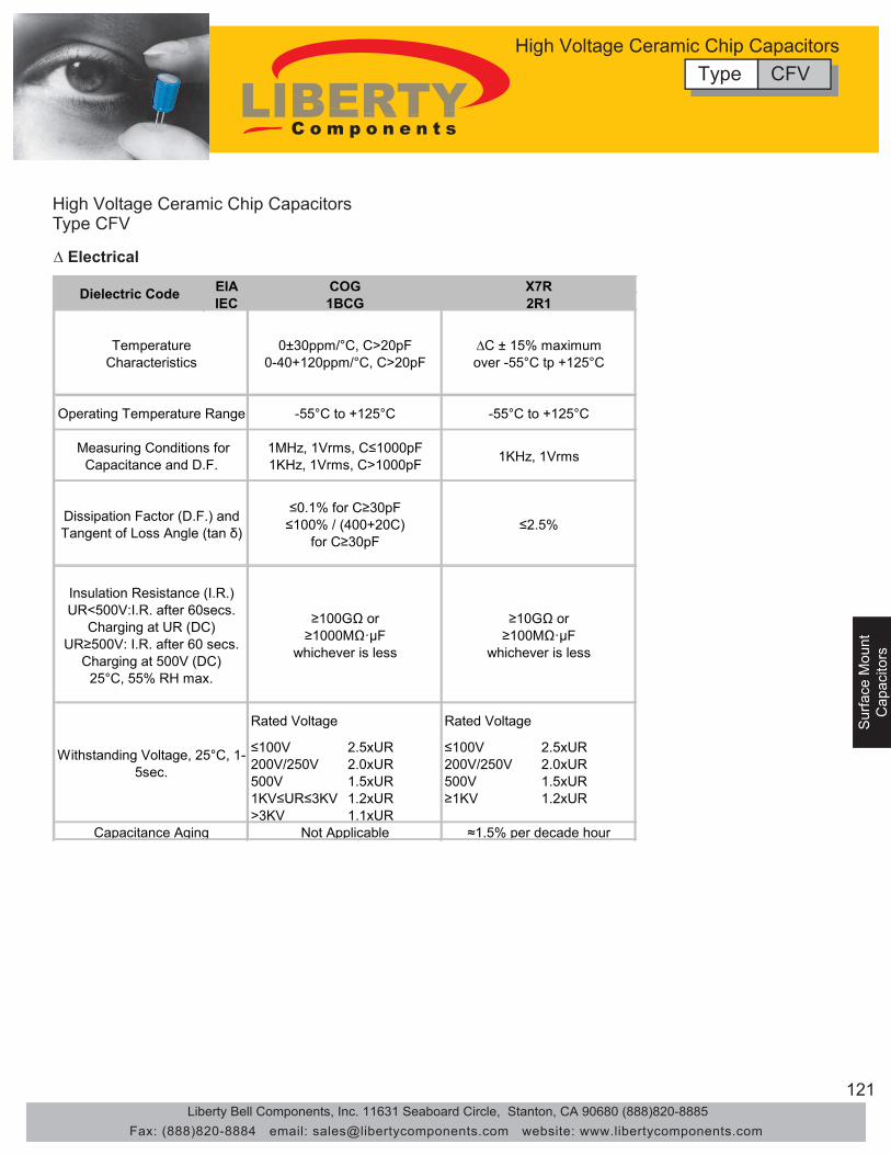
121
Surface M
ountC
apacitors
Sur
face
Mou
ntS
urfa
ce M
ount
Cap
acito
rsC
apac
itors
High Voltage Ceramic Chip Capacitors Type CFV
∆ Electrical
EIAIEC
≤100V 2.5xUR ≤100V 2.5xUR200V/250V 2.0xUR 200V/250V 2.0xUR500V 1.5xUR 500V 1.5xUR1KV≤UR≤3KV 1.2xUR ≥1KV 1.2xUR>3KV 1.1xUR
Dissipation Factor (D.F.) and Tangent of Loss Angle (tan δ)
Insulation Resistance (I.R.) UR<500V:I.R. after 60secs.
Charging at UR (DC) UR≥500V: I.R. after 60 secs.
Charging at 500V (DC)25°C, 55% RH max.
Withstanding Voltage, 25°C, 1-5sec.
Capacitance Aging Not Applicable ≈1.5% per decade hour
Rated Voltage Rated Voltage
1KHz, 1Vrms
≤2.5%
≥10GΩ or≥100MΩ·μF
whichever is less
≤0.1% for C≥30pF≤100% / (400+20C)
for C≥30pF
≥100GΩ or≥1000MΩ·μF
whichever is less
X7R2R1
∆C ± 15% maximumover -55°C tp +125°C
-55°C to +125°C
Dielectric Code1BCGCOG
0±30ppm/°C, C>20pF0-40+120ppm/°C, C>20pF
-55°C to +125°C
1MHz, 1Vrms, C≤1000pF1KHz, 1Vrms, C>1000pF
TemperatureCharacteristics
Operating Temperature Range
Measuring Conditions for Capacitance and D.F.
Type CFVHigh Voltage Ceramic Chip Capacitors
Liberty Bell Components, Inc. 11631 Seaboard Circle, Stanton, CA 90680 (888)820-8885Fax: (888)820-8884 email: [email protected] website: www.libertycomponents.com
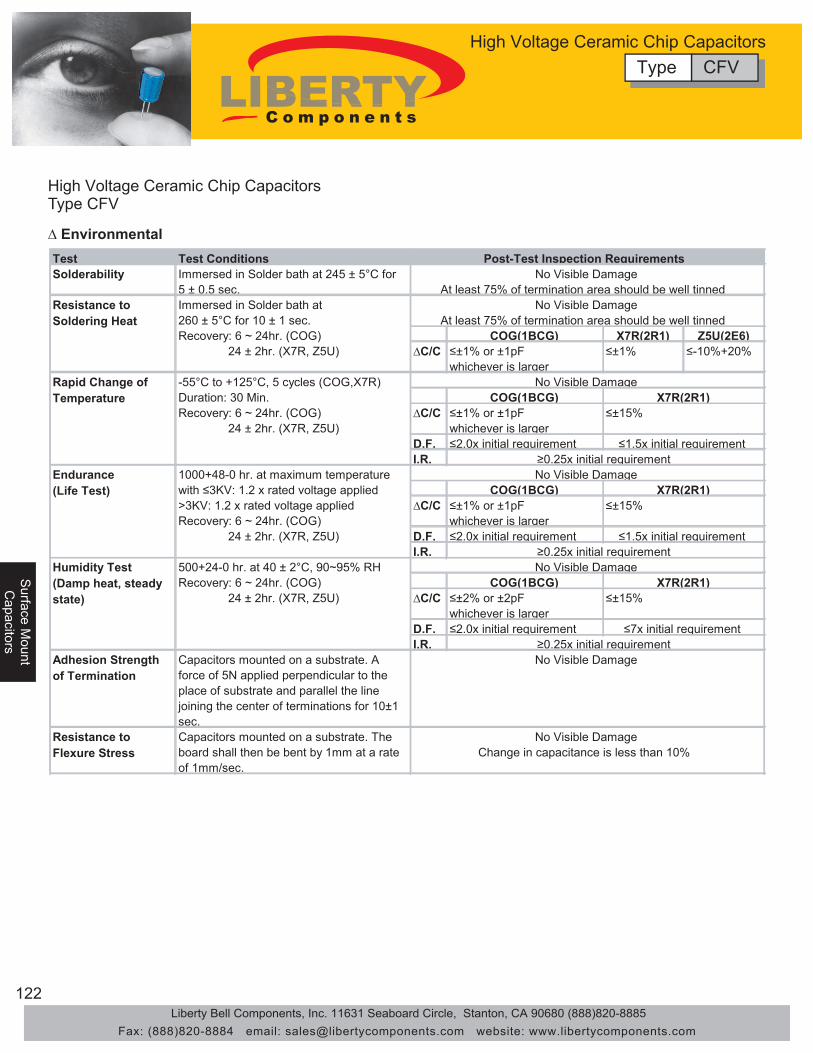
122
Surface M
ountS
urface Mount
Capacitors
Capacitors
Sur
face
Mou
ntC
apac
itors
High Voltage Ceramic Chip Capacitors Type CFV
∆ Environmental Test Test Conditions Solderability Immersed in Solder bath at 245 ± 5°C for
5 ± 0.5 sec.
COG(1BCG) X7R(2R1) Z5U(2E6) ∆C/C ≤±1% or ±1pF
whichever is larger ≤±1% ≤-10%+20%
COG(1BCG) ∆C/C ≤±1% or ±1pF
whichever is larger D.F. ≤2.0x initial requirement I.R.
COG(1BCG) ∆C/C ≤±1% or ±1pF
whichever is larger D.F. ≤2.0x initial requirement I.R.
COG(1BCG) ∆C/C ≤±2% or ±2pF
whichever is larger D.F. ≤2.0x initial requirement I.R.
Adhesion Strength of Termination
Capacitors mounted on a substrate. A force of 5N applied perpendicular to the place of substrate and parallel the line joining the center of terminations for 10±1 sec.
Resistance to Flexure Stress
Capacitors mounted on a substrate. The board shall then be bent by 1mm at a rate of 1mm/sec.
No Visible Damage
No Visible Damage Change in capacitance is less than 10%
Post-Test Inspection Requirements No Visible Damage
At least 75% of termination area should be well tinned No Visible Damage
At least 75% of termination area should be well tinned
No Visible Damage
No Visible Damage X7R(2R1)
≤±15%
≤7x initial requirement ≥0.25x initial requirement
Humidity Test (Damp heat, steady state)
500+24-0 hr. at 40 ± 2°C, 90~95% RH Recovery: 6 ~ 24hr. (COG) 24 ± 2hr. (X7R, Z5U)
Immersed in Solder bath at 260 ± 5°C for 10 ± 1 sec. Recovery: 6 ~ 24hr. (COG) 24 ± 2hr. (X7R, Z5U)
Resistance to Soldering Heat
≥0.25x initial requirement
-55°C to +125°C, 5 cycles (COG,X7R) Duration: 30 Min. Recovery: 6 ~ 24hr. (COG) 24 ± 2hr. (X7R, Z5U)
Rapid Change of Temperature
No Visible Damage Endurance(Life Test)
1000+48-0 hr. at maximum temperature with ≤3KV: 1.2 x rated voltage applied >3KV: 1.2 x rated voltage applied Recovery: 6 ~ 24hr. (COG) 24 ± 2hr. (X7R, Z5U)
≤±15%
≤1.5x initial requirement
X7R(2R1)
X7R(2R1) ≤±15%
≤1.5x initial requirement ≥0.25x initial requirement
Type CFVHigh Voltage Ceramic Chip Capacitors
Liberty Bell Components, Inc. 11631 Seaboard Circle, Stanton, CA 90680 (888)820-8885Fax: (888)820-8884 email: [email protected] website: www.libertycomponents.com

123
Surface M
ountC
apacitors
Sur
face
Mou
ntS
urfa
ce M
ount
Cap
acito
rsC
apac
itors
High Voltage Ceramic Chip Capacitors Type CFV
∆ Ordering CFV 2211 N - 100 J - 602 E F G (1) (2) (3) (4) (5) (6) (7) (8) (9)
(1) Series CFV:(2) 1808
18122211
N: COG (1BCG)X: X7R (2R1)
(4) Capacitance Code
Code ToleranceC ±0.25pFD ±0.5pFF ±1%G ±2%J ±5%K ±10%M ±20%Z +80% -20%
(6) 402 4000V502 5000V602 6000VTR: Tape and Reel, Cardboard TapeER: Tape and Reel, Embossed Tape
No Code: BulkCode Tolerance (mm)
E 1.51-1.80F 1.81-2.20G 2.21-2.70
(9) Special Code G: Cd/Pb Free
(8) Thickness Code
(7) Packaging Code
Size Code
Rated Voltage Code
Capacitance expressed in pF. First two digits are significant figures. The third Digit denotes number of zeros. Use R for decimal point for values less than 10pF. (eg. R47: 0.47pF)
Other Tolerances Available Upon Request
(3) Dielectric Code
(5) Tolerance Code
Type CFVHigh Voltage Ceramic Chip Capacitors
Liberty Bell Components, Inc. 11631 Seaboard Circle, Stanton, CA 90680 (888)820-8885Fax: (888)820-8884 email: [email protected] website: www.libertycomponents.com
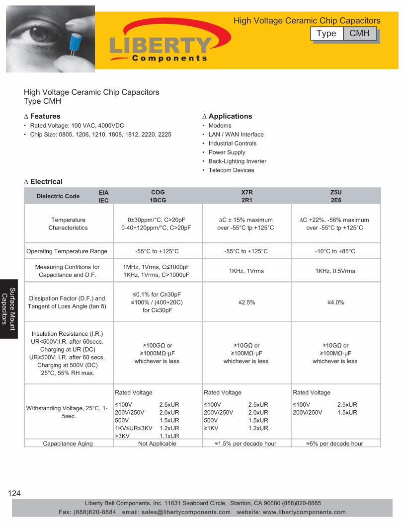
124
Surface M
ountS
urface Mount
Capacitors
Capacitors
Sur
face
Mou
ntC
apac
itors
High Voltage Ceramic Chip Capacitors Type CMH
∆ Features • Rated Voltage: 100 VAC, 4000VDC • Chip Size: 0805, 1206, 1210, 1808, 1812, 2220, 2225
∆ Applications
• LAN / WAN Interface
• Telecom Devices
∆ Electrical
• Industrial Controls• Power Supply• Back-Lighting Inverter
• Modems
EIAIEC
≤100V 2.5xUR ≤100V 2.5xUR ≤100V 2.5xUR200V/250V 2.0xUR 200V/250V 2.0xUR 200V/250V 1.5xUR500V 1.5xUR 500V 1.5xUR1KV≤UR≤3KV 1.2xUR ≥1KV 1.2xUR>3KV 1.1xUR
Not Applicable ≈1.5% per decade hour ≈5% per decade hour
TemperatureCharacteristics
Operating Temperature Range
Measuring Confitions for Capacitance and D.F.
Dissipation Factor (D.F.) and Tangent of Loss Angle (tan δ)
Insulation Resistance (I.R.) UR<500V:I.R. after 60secs.
Charging at UR (DC) UR≥500V: I.R. after 60 secs.
Charging at 500V (DC)25°C, 55% RH max.
Withstanding Voltage, 25°C, 1-5sec.
Capacitance Aging
Rated Voltage Rated Voltage Rated Voltage
1KHz, 1Vrms
≤2.5%
≥10GΩ or≥100MΩ·μF
whichever is less
Z5U2E6
∆C +22%, -56% maximumover -55°C tp +125°C
-10°C to +85°C
1KHz, 0.5Vrms
≤4.0%
≥10GΩ or≥100MΩ·μF
whichever is less
X7R2R1
∆C ± 15% maximumover -55°C tp +125°C
-55°C to +125°C-55°C to +125°C
1MHz, 1Vrms, C≤1000pF1KHz, 1Vrms, C>1000pF
≤0.1% for C≥30pF≤100% / (400+20C)
for C≥30pF
≥100GΩ or≥1000MΩ·μF
whichever is less
Dielectric Code 1BCGCOG
0±30ppm/°C, C>20pF0-40+120ppm/°C, C>20pF
Type CMHHigh Voltage Ceramic Chip Capacitors
Liberty Bell Components, Inc. 11631 Seaboard Circle, Stanton, CA 90680 (888)820-8885Fax: (888)820-8884 email: [email protected] website: www.libertycomponents.com

125
Surface M
ountC
apacitors
Sur
face
Mou
ntS
urfa
ce M
ount
Cap
acito
rsC
apac
itors
High Voltage Ceramic Chip Capacitors Type CMH
∆ Environmental Test Test Conditions Solderability Immersed in Solder bath at 245 ± 5°C for
5 ± 0.5 sec.
COG(1BCG) X7R(2R1) Z5U(2E6) ∆C/C ≤±1% or ±1pF
whichever is larger ≤±1% ≤-10%+20%
COG(1BCG) ∆C/C ≤±1% or ±1pF
whichever is larger D.F. ≤2.0x initial requirement I.R.
COG(1BCG) ∆C/C ≤±1% or ±1pF
whichever is larger D.F. ≤2.0x initial requirement I.R.
COG(1BCG) ∆C/C ≤±2% or ±2pF
whichever is larger D.F. ≤2.0x initial requirement I.R.
Adhesion Strength of Termination
Capacitors mounted on a substrate. A force of 5N applied perpendicular to the place of substrate and parallel the line joining the center of terminations for 10±1 sec.
Resistance to Flexure Stress
Capacitors mounted on a substrate. The board shall then be bent by 1mm at a rate of 1mm/sec.
No Visible Damage
No Visible Damage Change in capacitance is less than 10%
Post-Test Inspection Requirements No Visible Damage
At least 75% of termination area should be well tinned No Visible Damage
At least 75% of termination area should be well tinned
No Visible Damage
No Visible Damage X7R(2R1)
≤±15%
≤7x initial requirement ≥0.25x initial requirement
Humidity Test (Damp heat, steady state)
500+24-0 hr. at 40 ± 2°C, 90~95% RH Recovery: 6 ~ 24hr. (COG) 24 ± 2hr. (X7R, Z5U)
Immersed in Solder bath at 260 ± 5°C for 10 ± 1 sec. Recovery: 6 ~ 24hr. (COG) 24 ± 2hr. (X7R, Z5U)
Resistance to Soldering Heat
≥0.25x initial requirement
-55°C to +125°C, 5 cycles (COG,X7R) Duration: 30 Min. Recovery: 6 ~ 24hr. (COG) 24 ± 2hr. (X7R, Z5U)
Rapid Change of Temperature
No Visible Damage Edurance (Life Test)
1000+48-0 hr. at maximum temperature with ≤3KV: 1.2 x rated voltage applied >3KV: 1.2 x rated voltage applied Recovery: 6 ~ 24hr. (COG) 24 ± 2hr. (X7R, Z5U)
≤±15%
≤1.5x initial requirement
X7R(2R1)
X7R(2R1) ≤±15%
≤1.5x initial requirement ≥0.25x initial requirement
Type CMHHigh Voltage Ceramic Chip Capacitors
Liberty Bell Components, Inc. 11631 Seaboard Circle, Stanton, CA 90680 (888)820-8885Fax: (888)820-8884 email: [email protected] website: www.libertycomponents.com

126
Surface M
ountS
urface Mount
Capacitors
Capacitors
Sur
face
Mou
ntC
apac
itors
High Voltage Ceramic Chip Capacitors Type CMH
∆ Dimensions Size Length / Width Volt Capacitance
100 10pF±0.015μF 250 10pF±0.012μF 500 10pF±6800pF
1000 10pF±4700μF 2000 10pF±1200μF 3000 10pF±470μF 100 10pF±3300pF 250 10pF±3300pF 500 10pF±3300pF
1000 3pF±2200pF 2000 3pF±560pF 3000 3pF±470pF 4000 3pF±100pF 100 10pF±0.010μF 250 10pF±6800pF 500 10pF±4700pF
1000 10pF±2200pF 2000 10pF±560pF 3000 10pF±220pF 100 10pF±4700pF 250 10pF±3900pF 500 10pF±2200pF
1000 10pF±1500pF 2000 10pF±270pF 3000 10pF±68pF 100 10pF±1800pF 250 10pF±1200pF 500 10pF±470pF
0603 L: 1.60±0.015mm (0.063±0.006) W: 0.80±0.015mm (0.032±0.006)
100 10pF±1000pF
1210 L: 3.20±0.030mm (0.126±0.012) W: 2.50±0.030mm (0.100±0.012)
100 0.22pF±0.56μF
1206 L: 3.20±0.020mm (0.126±0.008) W: 1.60±0.020mm (0.063±0.008)
100 0.10pF±0.47μF
0805 L: 1.60±0.015mm (0.063±0.006) W: 0.80±0.015mm (0.032±0.006)
100 0.047pF±0.1μF
NPO
1812
1808
1210
1206
0805
L: 5.70±0.040mm (0.224±0.016) W: 2.80±0.030mm (0.112±0.012)
Z5U
L: 4.50±0.030mm (0.177±0.012) W: 3.20±0.030mm (0.126±0.012)
L: 3.20±0.030mm (0.126±0.012) W: 2.50±0.030mm (0.100±0.012)
L: 3.20±0.020mm (0.126±0.008) W: 1.60±0.020mm (0.063±0.008)
L: 2.00±0.020mm (0.080±0.008) W: 1.20±0.020mm (0.050±0.008)
Type CMHHigh Voltage Ceramic Chip Capacitors
Liberty Bell Components, Inc. 11631 Seaboard Circle, Stanton, CA 90680 (888)820-8885Fax: (888)820-8884 email: [email protected] website: www.libertycomponents.com
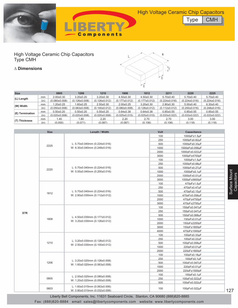
127
Surface M
ountC
apacitors
Sur
face
Mou
ntS
urfa
ce M
ount
Cap
acito
rsC
apac
itors
High Voltage Ceramic Chip Capacitors Type CMH
∆ Dimensions
Size 0805 1206 1210 1808 1812 2211 2220 2225 mm 2.00±0.30 3.20±0.20 3.20±0.30 4.50±0.30 4.50±0.30 5.70±0.40 5.70±0.40 5.70±0.40 (in) (0.080±0.008) (0.126±0.008) (0.126±0.012) (0.177±0.012) (0.177±0.012) (0.224±0.016) (0.224±0.016) (0.224±0.016) mm 1.20±0.25 1.60±0.25 2.50±0.30 2.00±0.25 3.20±0.30 2.80±0.30 5.00±0.40 6.30±0.40 (in) (0.050±0.008) (0.063±0.008) (0.100±0.012) (0.080±0.008) (0.126±0.012) (0.112±0.012) (0.200±0.016) (0.248±0.016) mm 0.50±0.20 0.50±0.20 0.50±0.20 0.64±0.38 0.64±0.38 0.85±0.55 0.85±0.55 0.85±0.55 (in) (0.020±0.008) (0.020±0.008) (0.020±0.008) (0.025±0.015) (0.025±0.015) (0.033±0.022) (0.033±0.022) (0.033±0.022) mm 1.40 1.80 2.20 2.20 2.70 2.70 3.00 3.00 (in) (0.055) (0.071) (0.087) (0.087) (0.106) (0.106) (0.118) (0.118)
(L) Length
(W) Width
(E) Termination
(T) Thickness
Size Length / Width Volt Capacitance 100 1000pF±1.5μF 250 1000pF±0.82μF 500 1000pF±0.33μF
1000 1000pF±0.056μF 2000 1000pF±0.022μF 3000 1000pF±4700pF 100 1000pF±1.5μF 250 1000pF±0.68μF 500 1000pF±0.27μF
1000 1000pF±0.1μF 2000 1000pF±0.01μF 3000 1000pF±5600pF 100 470pF±1.0μF 250 470pF±0.47μF 500 470pF±0.15μF
1000 470pF±0.056μF 2000 470pF±4700pF 3000 470pF±2700μF 100 150pF±0.047μF 250 150pF±0.047μF 500 150pF±0.068μF
1000 150pF±0.01μF 2000 150pF±2200pF 3000 150pF±1800pF 4000 470pF±1000pF 100 100pF±0.33μF 250 100pF±0.22μF 500 100pF±0.056μF
1000 220pF±0.01μF 2000 220pF±1800pF 100 100pF±0.18μF 250 100pF±0.1μF 500 100pF±0.047μF
1000 220pF±0.01μF 2000 220pF±1500pF 100 100pF±0.1μF 250 100pF±0.022μF 500 100pF±0.022μF
0603 L: 1.60±0.015mm (0.063±0.006)
W: 0.80±0.015mm (0.032±0.006) 100 100pF±0.022μF
X7R
2225
2220
1812
1808
1210
1206
0805
L: 5.70±0.040mm (0.224±0.016) W: 6.30±0.040mm (0.248±0.016)
L: 5.70±0.040mm (0.224±0.016) W: 5.00±0.040mm (0.200±0.016)
L: 5.70±0.040mm (0.224±0.016) W: 2.80±0.030mm (0.112±0.012)
L: 4.50±0.030mm (0.177±0.012) W: 3.20±0.030mm (0.126±0.012)
L: 3.20±0.030mm (0.126±0.012) W: 2.50±0.030mm (0.100±0.012)
L: 3.20±0.020mm (0.126±0.008) W: 1.60±0.020mm (0.063±0.008)
L: 2.00±0.020mm (0.080±0.008) W: 1.20±0.020mm (0.050±0.008)
Type CMHHigh Voltage Ceramic Chip Capacitors
Liberty Bell Components, Inc. 11631 Seaboard Circle, Stanton, CA 90680 (888)820-8885Fax: (888)820-8884 email: [email protected] website: www.libertycomponents.com
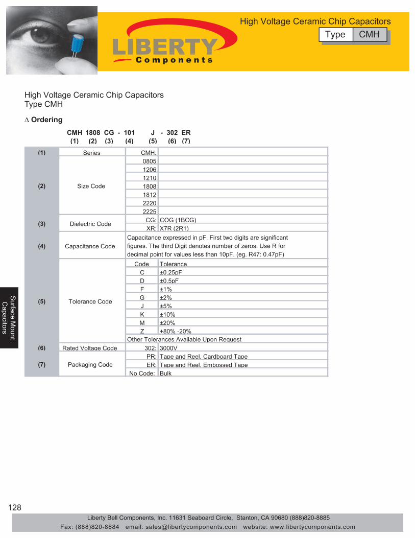
128
Surface M
ountS
urface Mount
Capacitors
Capacitors
Sur
face
Mou
ntC
apac
itors
High Voltage Ceramic Chip Capacitors Type CMH
∆ Ordering
Type CMHHigh Voltage Ceramic Chip Capacitors
CMH 1808 CG - 101 J - 302 ER(1) (2) (3) (4) (5) (6) (7)
(1) Series CMH:0805120612101808181222202225CG: COG (1BCG)XR: X7R (2R1)
(4) Capacitance Code
Code ToleranceC ±0.25pFD ±0.5pFF ±1%G ±2%J ±5%K ±10%M ±20%Z +80% -20%
(6) Rated Voltage Code 302: 3000VPR: Tape and Reel, Cardboard TapeER: Tape and Reel, Embossed Tape
No Code: Bulk(7) Packaging Code
Capacitance expressed in pF. First two digits are significant figures. The third Digit denotes number of zeros. Use R for decimal point for values less than 10pF. (eg. R47: 0.47pF)
Other Tolerances Available Upon Request
(2) Size Code
(3) Dielectric Code
(5) Tolerance Code
Liberty Bell Components, Inc. 11631 Seaboard Circle, Stanton, CA 90680 (888)820-8885Fax: (888)820-8884 email: [email protected] website: www.libertycomponents.com

129
Surface M
ountC
apacitors
Sur
face
Mou
ntS
urfa
ce M
ount
Cap
acito
rsC
apac
itors
PPTCType PSSM
∆ Electrical Characteristics
∆ Typical T-I Derating Form
IH IT Vmax Imax (A) Rmin Rmax R1max(A) (A) (A) (S) (V) (A) (Ω) (Ω) (Ω)
PSSM-030 0.30 0.60 11.5 4.0 60 10 0.700 1.300 4.800PSSM-050 0.50 1.00 2.5 4.0 30 10 0.350 0.600 1.400PSSM-075 0.75 1.50 8.0 3.0 30 40 0.290 0.400 1.000PSSM-110 1.10 2.20 8.0 2.0 15 40 0.100 0.190 0.480PSSM-125 1.25 2.50 8.0 2.0 15 40 0.070 0.120 0.250PSSM-130 1.30 2.60 8.0 4.0 15 40 0.080 0.130 0.280PSSM-150 1.50 3.00 8.0 5.0 15 40 0.060 0.110 0.250PSSM-185 1.85 3.70 8.0 5.0 15 40 0.450 0.080 0.165PSSM-200 2.00 4.00 8.0 12.0 15 40 0.450 0.065 0.125PSSM-250 2.50 5.00 8.0 25.0 15 40 0.250 0.052 0.085PSSM-260 2.60 5.20 8.0 20.0 6 40 0.250 0.052 0.075PSSM-300 3.00 6.00 8.0 35.0 6 40 0.150 0.330 0.048
TtripModel
-40 -20 0 25 40 50 60 70 85 PSSM-030 0.45 0.40 0.35 0.30 0.25 0.23 0.20 0.17 0.14 PSSM-050 0.76 0.67 0.59 0.50 0.42 0.38 0.33 0.29 0.23 PSSM-075 1.13 1.01 0.88 0.75 0.62 0.56 0.50 0.44 0.34 PSSM-110 1.66 1.47 1.29 1.10 0.91 0.83 0.73 0.64 0.50 PSSM-125 1.89 1.68 1.46 1.25 1.04 0.94 0.83 0.73 0.56 PSSM-150 2.27 2.01 1.76 1.50 1.25 1.31 1.00 0.87 0.68 PSSM-185 2.20 2.08 1.96 1.85 1.70 1.66 1.50 1.48 1.40 PSSM-200 3.02 2.68 2.34 2.00 1.66 1.50 1.32 1.16 0.90 PSSM-250 3.78 3.35 2.93 2.50 2.08 1.88 1.65 1.45 1.13 PSSM-260 3.64 3.25 2.91 2.60 2.26 2.08 1.95 1.74 1.48 PSSM-300 4.01 3.67 3.32 3.00 2.60 2.40 2.25 2.10 1.80
Model Ambient Temperature (°C)
E
H
D
B
A
F
C
G
∆ Dimensions
∆ Application• Medical, telecom and consumer electronic equipment.• Miniature PCB.
∆ Feature• Fuse Capacitor (Replaces traditional fuses in DC applications)• Auto Reset (when power is cycled)
Type PSPPTC
PS-SM
Legend
IH(A): Hold current: maximum current at which the device will not trip at 25°C still air
IT(A): Tripping current: minimum current at which the device will trip at 25°C under specified conditions.
TT(S): Maximum time to trip at specified current. (generally at 5IH)
Vmax(V): Maximum device operating voltage.
Imax(A): Maximum fault current device can withstand without damage at rated voltage.
Pdtyp(W): Typical power dissipation: Typical amount of power dissapated by the device when in tripped state air environment.
Ro(Ω): Minimum-maximum device resistance at 25° prior to tripping.
Liberty Bell Components, Inc. 11631 Seaboard Circle, Stanton, CA 90680 (888)820-8885Fax: (888)820-8884 email: [email protected] website: www.libertycomponents.com

130
Surface M
ountS
urface Mount
Capacitors
Capacitors
Sur
face
Mou
ntC
apac
itors
PPTCType PS-SM
∆ Dimensions
Min Max Max Min PSSM-030 6.73 7.98 0.56 0.71 PSSM-050 6.73 7.98 0.56 0.71 PSSM-075 6.73 7.98 0.56 0.71 PSSM-110 6.73 7.98 0.56 0.71 PSSM-125 6.73 7.98 0.56 0.71 PSSM-130 8.00 9.50 0.56 0.71 PSSM-150 8.00 9.50 0.56 0.71 PSSM-185 8.00 9.50 0.56 0.71 PSSM-200 8.00 9.50 0.56 0.71 PSSM-250 8.00 9.50 0.56 0.71 PSSM-260 6.73 7.98 0.56 0.71 PSSM-300 6.73 7.98 0.56 0.71
Min Max Min Max Min Max PSSM-030 0.56 0.71 2.16 2.41 0.66 1.37 PSSM-050 0.56 0.71 2.16 2.41 0.66 1.37 PSSM-075 0.56 0.71 2.16 2.41 0.66 1.37 PSSM-110 0.56 0.71 2.16 2.41 0.66 1.37 PSSM-125 0.56 0.71 2.16 2.41 0.66 1.37 PSSM-130 0.56 0.71 2.16 2.41 0.66 1.37 PSSM-150 0.56 0.71 3.68 3.94 0.66 1.37 PSSM-185 0.56 0.71 3.68 3.94 0.66 1.37 PSSM-200 0.56 0.71 3.68 3.94 0.66 1.37 PSSM-250 0.56 0.71 3.68 3.94 0.66 1.37 PSSM-260 0.56 0.71 2.16 2.41 0.66 1.37 PSSM-300 0.56 0.71 2.16 2.41 0.66 1.37
A B C Nom Nom Nom
PSSM-030 3.1 2.3 9.7 PSSM-050 3.1 2.3 9.7 PSSM-075 3.1 2.3 9.7 PSSM-110 3.1 2.3 9.7 PSSM-125 3.1 2.3 9.7 PSSM-130 3.1 2.3 9.7 PSSM-150 4.6 2.3 10.7 PSSM-185 4.6 2.3 10.7 PSSM-200 4.6 2.3 10.7 PSSM-250 4.6 2.3 10.7 PSSM-260 3.1 2.3 9.7 PSSM-300 3.1 2.3 9.7
0.43 0.43 0.43
0.43 0.43 0.43 0.43
0.43 0.43 0.43 0.43
Model
H Max 0.43
Model E F G
3.00 3.18 3.18
Model A
3.00 3.00 3.00 3.00
5.44 5.00
D B Max 3.18 3.18 3.18 3.00 3.00
6.71 6.71 6.71 6.71
5.44 5.00 6.71 6.71
C Max 5.44 5.44
B
A
C
B
A
Type PSPPTC
PS-SM
units: mm
Liberty Bell Components, Inc. 11631 Seaboard Circle, Stanton, CA 90680 (888)820-8885Fax: (888)820-8884 email: [email protected] website: www.libertycomponents.com

131
Surface M
ountC
apacitors
Sur
face
Mou
ntS
urfa
ce M
ount
Cap
acito
rsC
apac
itors
PPTC Type PS-WSM
∆ Electrical Characteristics
∆ Typical T-I Derating Form
IH IT Vmax Imax (A) Rmin R1max(A) (A) (A) (S) (V) (A) (Ω) (Ω)
PSWSM-010 0.10 0.20 1.5 0.15 60.0 10 0.700 6.000PSWSM-014 0.14 0.28 1.5 0.15 60.0 10 0.700 6.000PSWSM-020 0.20 0.40 6.0 0.06 30.0 10 0.600 5.000PSWSM-035 0.35 0.70 8.0 0.20 6.0 40 - 1.300PSWSM-050 0.50 1.00 8.0 0.15 15.0 40 0.150 1.000PSWSM-075 0.75 1.50 8.0 0.20 13.2 40 0.100 0.480PSWSM-110 1.10 2.20 8.0 0.30 6.0 40 0.040 0.260PSWSM-125 1.25 2.50 8.0 0.40 6.0 40 0.070 0.250PSWSM-150 1.50 3.00 8.0 0.50 6.0 40 0.040 0.110PSWSM-160 1.60 3.20 8.0 1.00 6.0 40 0.030 0.100PSWSM-190 1.90 3.80 10.0 2.00 16.0 100 0.024 0.080PSWSM-200 2.00 4.00 8.0 2.00 6.0 40 0.020 0.060PSWSM-260 2.60 5.20 8.0 2.00 6.0 40 0.015 0.047
TtripModel
-40 -20 0 25 40 50 60 70 85 PSWSM-014 0.23 0.19 0.17 0.14 0.12 0.10 0.09 0.08 0.06 PSWSM-020 0.29 0.26 0.23 0.20 0.17 0.15 0.14 0.12 0.10 PSWSM-035 0.47 0.45 0.40 0.35 0.30 0.28 0.24 0.21 0.18 PSWSM-050 0.77 0.68 0.59 0.50 0.44 0.40 0.37 0.33 0.29 PSWSM-075 1.15 1.01 0.88 0.75 0.65 0.60 0.55 0.49 0.43 PSWSM-110 1.59 1.43 1.26 1.10 0.95 0.87 0.80 0.71 0.60 PSWSM-190 3.04 2.70 2.20 1.90 1.44 1.23 1.00 0.78 0.49
Model Ambient Temperature (°C)
Type PSPPTC
PS-WSM
Legend
IH(A): Hold current: maximum current at which the device will not trip at 25°C still air
IT(A): Tripping current: minimum current at which the device will trip at 25°C under specified conditions.
TT(S): Maximum time to trip at specified current. (generally at 5IH)
Vmax(V): Maximum device operating voltage.
Imax(A): Maximum fault current device can withstand without damage at rated voltage.
Pdtyp(W): Typical power dissipation: Typical amount of power dissapated by the device when in tripped state air environment.
Ro(Ω): Minimum-maximum device resistance at 25° prior to tripping.
∆ Application• Medical, telecom and consumer electronic equipment.• Miniature PCB.
∆ Feature• Fuse Capacitor (Replaces traditional fuses in DC applications)• Auto Reset (when power is cycled)
Liberty Bell Components, Inc. 11631 Seaboard Circle, Stanton, CA 90680 (888)820-8885Fax: (888)820-8884 email: [email protected] website: www.libertycomponents.com

132
Surface M
ountS
urface Mount
Capacitors
Capacitors
Sur
face
Mou
ntC
apac
itors
PPTC Type PSWSM
∆ DimensionsA B C
Amax Bmax Cmax Nom Nom Nom PSWSM-010 4.73 3.41 0.81 3.45 1.78 3.15 PSWSM-014 4.73 3.41 0.81 3.45 1.78 3.15 PSWSM-020 4.73 3.41 0.62 3.45 1.78 3.15 PSWSM-035 3.43 2.80 0.62 2.00 1.00 2.50 PSWSM-050 4.73 3.41 0.62 3.45 1.78 3.15 PSWSM-075 4.73 3.41 0.62 3.45 1.78 3.15 PSWSM-110 4.73 3.41 1.25 3.45 1.78 3.15 PSWSM-125 4.73 3.41 1.25 3.45 1.78 3.15 PSWSM-150 4.73 3.41 1.25 3.45 1.78 3.15 PSWSM-160 4.73 3.41 1.25 3.45 1.78 3.15 PSWSM-190 11.51 5.33 0.55 9.57 1.45 4.75 PSWSM-200 4.73 3.41 1.25 3.45 1.78 3.15 PSWSM-260 4.73 3.41 2.25 3.45 1.78 3.15
Model
B
A C B B A
C
Terminals
Type PSPPTC
PS-WSM
units: mm
Liberty Bell Components, Inc. 11631 Seaboard Circle, Stanton, CA 90680 (888)820-8885Fax: (888)820-8884 email: [email protected] website: www.libertycomponents.com

133
Surface M
ountC
apacitors
Sur
face
Mou
ntS
urfa
ce M
ount
Cap
acito
rsC
apac
itors
PPTCType PSxxx
∆ Electrical Characteristics
∆ Typical T-I Derating Form
-40 -20 0 25 40 50 60 70 85 PS070 1.32 1.21 0.99 0.70 0.63 0.60 0.50 0.39 0.26 PS100 2.00 1.73 1.52 1.00 0.99 0.85 0.75 0.61 0.40 PS120 1.95 1.74 1.54 1.20 1.07 0.98 0.87 0.76 0.58
PS-CW170 3.20 2.70 2.20 1.70 1.30 1.10 0.80 0.60 - PS175 2.57 2.36 2.07 1.75 1.59 1.39 1.27 1.18 0.99
PS-CW175 3.20 2.70 2.20 1.75 1.30 1.00 0.80 0.50 - PS180 3.23 2.88 2.35 1.80 1.48 1.20 1.10 0.75 0.45 PS190 3.50 3.00 2.51 1.90 1.60 1.35 1.20 0.88 0.52 PS200 3.28 2.88 2.59 2.00 1.81 1.70 1.52 1.31 1.02
PS-CW200 3.70 3.20 2.60 2.00 1.50 1.20 0.90 0.50 - PS-CW210 4.10 3.50 2.90 2.10 1.60 1.30 1.00 0.70 - PS-CW240 4.40 3.70 3.10 2.40 1.80 1.50 1.20 0.90 - PS-CW250 4.60 3.90 3.30 2.50 1.90 1.60 1.40 1.20 -
PS260 4.40 3.80 3.19 2.60 2.10 1.80 1.49 1.19 0.70 PS300 5.20 4.49 3.78 3.00 2.39 2.04 1.70 1.35 0.78 PS310 5.46 4.68 3.80 3.10 2.45 2.11 1.80 1.40 0.80 PS340 5.60 4.88 4.10 3.40 2.70 2.33 2.00 1.60 0.89 PS350 5.51 4.89 4.42 3.50 3.00 2.89 2.62 2.28 1.79 PS420 6.53 5.81 5.20 4.20 3.69 3.38 3.10 2.75 2.24
Model Ambient Temperature (°C)
∆ Application• Rechargeable Nicad, Lithium Battery Packs.
Model Vmax (V) Ro (Ω) IT (A) TT (S) IH (A) PS070 15 0.100-0.200 1.45 ≤5.0 0.70 PS100 24 0.070-0.130 2.50 ≤7.0 1.00 PS120 15 0.085-0.160 2.70 ≤5.0 1.20
PS-CW120 15 0.085-0.160 2.70 ≤3.0 1.20 PS-CW170 15 0.030-0.052 3.40 ≤3.0 1.70
PS175 15 0.050-0.090 3.80 ≤5.0 1.75 PS-CW175 15 0.029-0.051 3.80 ≤5.0 1.75
PS180 24 0.040-0.068 3.80 ≤2.9 1.80 PS190 24 0.030-0.057 4.20 ≤3.0 1.90 PS200 24 0.030-0.060 4.40 ≤4.0 2.00
PS-CW200 15 0.022-0.039 4.50 ≤5.0 2.00 PS-CW210 15 0.018-0.030 4.70 ≤5.0 2.10 PS-CW240 15 0.014-0.026 5.40 ≤4.0 2.40 PS-CW250 15 0.017-0.046 5.20 ≤10.0* 2.50
PS260 24 0.025-0.042 5.20 ≤5.0 2.60 PS300 24 0.015-0.031 6.30 ≤4.0 3.00 PS310 24 0.018-0.030 6.00 ≤5.0 3.10 PS340 24 0.016-0.027 6.80 ≤5.0 3.40 PS350 24 0.017-0.031 6.30 ≤3.0** 3.50 PS420 24 0.012-0.024 7.60 ≤6.0 4.20
Note: All PS listed on this page have Imax (A): 100 τc (S): ≤60
Legend
IH(A): Hold current: maximum current at which the device will not trip at 25°C still air
IT(A): Tripping current: minimum current at whic hthe device will trip at 25°C under specified conditions.
TT(S): Maximum time to trip at specified current. (generally at 5IH)
Vmax(V): Maximum device operating voltage.
Imax(A): Maximum fault current device can withstand without damage at rated voltage.
Pdtyp(W): Typical power dissipation: Typical amount of power dissapated by the device when in tripped state air environment.
Ro(Ω): Minimum-maximum device resistance at 25° prior to tripping.
Type PSPPTC
PS-xxx
∆ Feature• Fuse Capacitor (Replaces traditional fuses in DC applications)• Auto Reset (when power is cycled)
Liberty Bell Components, Inc. 11631 Seaboard Circle, Stanton, CA 90680 (888)820-8885Fax: (888)820-8884 email: [email protected] website: www.libertycomponents.com

134
Surface M
ountS
urface Mount
Capacitors
Capacitors
Sur
face
Mou
ntC
apac
itors
PPTC Type PSxxx
∆ DimensionsModel Atyp (mm) Btyp (mm) Ctyp (mm) Dtyp (mm) Etyp (mm)PS070 20.0 5.2 0.9 6.0 4.0PS100 20.0 5.2 0.8 6.0 4.0PS120 20.0 5.2 0.8 6.0 4.0
PS-CW120 22.0 7.3 1.0 5.0 4.0PS-CW170 17.5 5.2 1.0 5.0 4.0
PS175 22.0 3.8 0.8 5.0 3.2PS-CW175 22.0 5.2 1.0 5.0 4.0
PS180 22.0 8.2 0.8 5.0 5.0PS190 22.0 8.2 0.8 6.2 5.0PS200 22.0 3.8 0.8 6.2 3.2
PS-CW200 25.0 5.3 1.0 5.0 4.0PS-CW210 23.1 5.3 1.0 5.0 4.0PS-CW240 33.0 5.3 1.0 5.0 4.0PS-CW250 43.0 5.3 1.0 13.0 5.0
PS260 22.0 8.2 0.8 6.2 5.0PS300 27.0 13.3 0.8 6.0 5.0PS310 27.0 13.3 0.8 6.0 5.0PS340 27.0 13.3 0.8 6.0 5.0PS350 27.0 13.3 0.8 6.0 5.0PS420 31.0 13.3 0.8 6.3 5.0
A
B E
D DC
A
B E
D DC
0.5mm x 4.0 mm
0.01
0.1
1
10
100
1000
1 10 100
Fault Current (A)
Tim
e-to
-trip
(s)
0.01
0.1
1
10
100
1000
1 10 100
Fault Current (A)
Tim
e-to
-trip
(s)
QPONMLKJIHGFEDCBA MLKJIHGFEDCBA
A=PS60-010 E=PS60-030 I=PS60-075 M=PS60-160B=PS60-017 F=PS60-040 J=PS60-090 N=PS60-185C=PS60-020 G=PS60-050 K=PS60-110 O=PS60-250D=PS60-025 H=PS60-065 L=PS60-135 P=PS60-300
Q=PS60-375
A=PS30-090 D=PS30-160 G=PS30-300 J=PS30-600B=PS30-110 E=PS30-185 H=PS30-400 K=PS30-700C=PS30-135 F=PS30-250 I=PS30-500 L=PS30-800
M=PS30-900
Type PSPPTC
PS-xxx
units: mm
Liberty Bell Components, Inc. 11631 Seaboard Circle, Stanton, CA 90680 (888)820-8885Fax: (888)820-8884 email: [email protected] website: www.libertycomponents.com

135
Surface M
ountR
esistors
Sur
face
Mou
ntS
urfa
ce M
ount
Res
isto
rsR
esis
tors
Part Number
E-24 Series E-96 Series
Thick Film Chip ResistorsType MCR Series
∆ How to Order
∆ Resistance Marking
473 1542 0C2
ex. 473: 47x10^3 = 47KΩ105: 10x10^5 = 1MΩ1R5: 15x10^-1 = 1.5Ω
0: 0Ω
3 digit marking for E24
1R00
ex. 1R00: 1ΩR470 470mΩR010 10mΩ
4 digit marking for E241: Ω~10mΩex. 1542: 154x10^2 = 15K4Ω
4 digit marking for E96ex. 0C2 (see table)
102x10^2 = 10K2Ω
3 digit marking for E96 - 0603
• Small size and lightweight with size range per int’l standard.• Highly stable in auto-placement surface mounting application.• Compatible with flow and reflow soldering.
∆ Features
• Suitable for lead free soldering.
∆ Applications• Consumer electronics
• Automotive, industry• Computer
∆ Soldering Temperature Curve
Typical values (solid line).
Process limits (dotted line).WAVE soldering. IR Reflow Soldering
Peak : Less than 245˚C
230˚C
180˚C Pre Heating Zone
150˚C
Soldering Zone
0
t (s)
T(˚C )
90±30s 10 ~ 15s
Heating time50
250
200
150
100
second wave
0
0t (s)
200 K/s
2 K/s
200
250
150
100
50
50 100 150 200
2 K/s
5 K/s
250
T(˚C )
first wave
forcedcooling
10s
235˚C to 260˚C
100˚C to 130˚C
Example MCR 0603Type SizeMCR 0201 T: Tape B: ±0.1% 123 = 12x10^3 LF = Lead Free
0402 C: ±0.25% = 12k Ω0603 D: ±0.5%0805 F: ±1%1206 G: ±2%1210 J: ±5%20102512
LF123Resistance ValuePacking Tolerance
T J
• Medical equipment• Telecom equipment
Type MCRThick Film Chip Resistors
Liberty Bell Components, Inc. 11631 Seaboard Circle, Stanton, CA 90680 (888)820-8885Fax: (888)820-8884 email: [email protected] website: www.libertycomponents.com

136
Surface M
ountS
urface Mount
Resistors
Resistors
Sur
face
Mou
ntR
esis
tors
Thick Film Chip Resistors Type MCR Series
∆ Configuration
Protective Coating
High Purity Alumina Substrate
Resistive Element (RuO2)
Inner Termination Layer: Ag.Pd/Ag
Outer Termination Layer: Solder
Middle Termination Layer: Nickel
∆ Dimensions L
W
T
D
C
Size L W C D T 0201 0.60 ± 0.05 0.30 ± 0.05 0.25 ± 0.05 0.15 ± 0.05 0.25 ± 0.05 0402 1.00 ± 0.05 0.50 ± 0.05 0.20 ± 0.10 0.25 ± 0.10 0.35 ± 0.05 0603 1.60 ± 0.10 0.80 ± 0.10 0.30 ± 0.20 0.30 ± 0.20 0.45 ± 0.10 0805 2.00 ± 0.15 1.20 ± 0.15 0.40 ± 0.20 0.40 ± 0.20 0.50 ± 0.10 1206 3.10 ± 0.15 1.60 ± 0.15 0.50 ± 0.25 0.50 ± 0.25 0.55 ± 0.10 1210 3.10 ± 0.15 2.65 ± 0.15 0.50 ± 0.20 0.50 ± 0.25 0.55 ± 0.10 2010 5.00 ± 0.20 2.50 ± 0.20 0.60 ± 0.25 0.60 ± 0.25 0.60 ± 0.10 2512 6.30 ± 0.20 3.10 ± 0.20 0.60 ± 0.25 0.60 ± 0.25 0.60 ± 0.15 1225 3.10 ± 0.20 6.30 ± 0.20 0.60 ± 0.25 0.90 ± 0.25 0.60 ± 0.15
∆ Power Derating Curve
*Maximum dissipation in percentage of rated power as a function of the ambient temperature.
For All Except 0201
0
50
100
-50 0 50 100 150
Temperature (°C)
Rat
ed L
oad
(%)
For 0201 Only
0
50
100
-50 0 50 100 150
Temperature (°C)
Rat
ed L
oad
(%)
70 155 70 125
Type MCRThick Film Chip Resistors
units: mm
Liberty Bell Components, Inc. 11631 Seaboard Circle, Stanton, CA 90680 (888)820-8885Fax: (888)820-8884 email: [email protected] website: www.libertycomponents.com
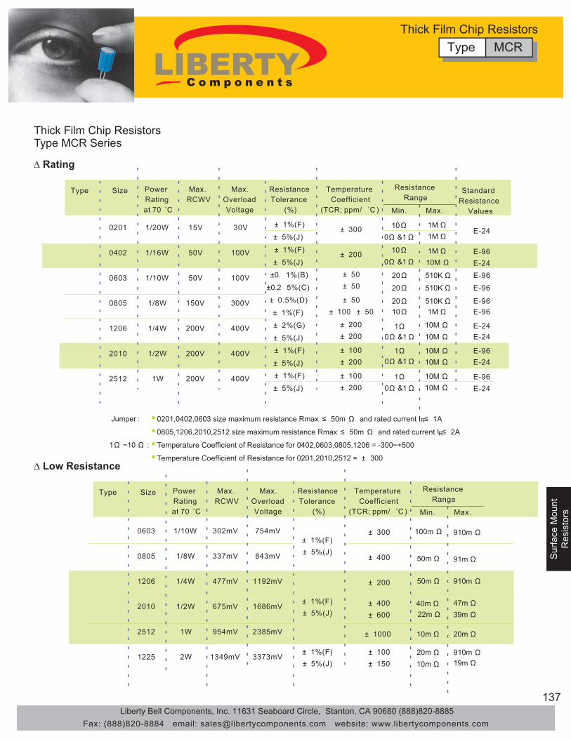
137
Surface M
ountR
esistors
Sur
face
Mou
ntS
urfa
ce M
ount
Res
isto
rsR
esis
tors
Thick Film Chip ResistorsType MCR Series
∆ Rating
∆ Low Resistance
Type Size
0201
0402
0603
0805
1206
2010
2512
Power Ratingat 70 ˚C
1/20W
1/16W
1/10W
1/8W
1/4W
1/2W
1W
Max.RCWV
15V
50V
50V
150V
200V
200V
200V
Max. OverloadVoltage
30V
100V
100V
300V
400V
400V
400V
± 300
± 200
± 50± 50
1M Ω1M Ω
1M Ω10M Ω
510K Ω
510K Ω
510K Ω1M Ω
10M Ω10M Ω
10M Ω10M Ω
10M Ω10M Ω
20Ω
20Ω
20Ω10Ω
1Ω0Ω &1Ω
1Ω0Ω &1Ω
1Ω0Ω &1Ω
10Ω0Ω &1Ω
10Ω0Ω &1Ω
± 200± 200
± 100± 200
± 100± 200
± 50± 100 ± 50
Resistance Tolerance
(%)
± 1%(F)
± 1%(F)
±0. 1%(B)
± 0.5%(D)
± 2%(G)
± 1%(F)
± 1%(F)
± 5%(J)
± 5%(J)
±0.2 5%(C)
± 1%(F)
± 5%(J)
± 5%(J)
± 5%(J)
Temperature Coefficient
(TCR; ppm/ ˚C )
ResistanceRange
Standard Resistance
ValuesMin. Max.
E-24
E-96 E-24 E-96
E-96
E-96 E-96
E-24 E-24
E-96 E-24
E-96 E-24
Type Size
0603
0805
1206
2010
2512
1225
Power Ratingat 70 ˚C
1/10W
1/8W
1/4W
1/2W
1W
2W
Max.RCWV
302mV
337mV
477mV
675mV
954mV
1349mV
Max. OverloadVoltage
754mV
843mV
1192mV
1686mV
2385mV
3373mV
± 300
± 400
± 200
910m Ω
91m Ω
910m Ω
20m Ω
47m Ω39m Ω
910m Ω19m Ω
40m Ω22m Ω
100m Ω
10m Ω
50m Ω
50m Ω
20m Ω10m Ω
± 400± 600
± 1%(F)± 5%(J)
± 1%(F)± 5%(J)
± 1%(F)± 5%(J)
± 100± 150
Resistance Tolerance
(%)
Temperature Coefficient
(TCR; ppm/ ˚C )
ResistanceRange
Min. Max.
± 1000
● 0201,0402,0603 size maximum resistance Rmax ≤ 50m Ω and rated current IR≤ 1A● 0805,1206,2010,2512 size maximum resistance Rmax ≤ 50m Ω and rated current IR≤ 2A●Temperature Coefficient of Resistance for 0402,0603,0805,1206 = -300~+500●Temperature Coefficient of Resistance for 0201,2010,2512 = ± 300
Jumper :
1Ω ~10 Ω :
Type MCRThick Film Chip Resistors
Liberty Bell Components, Inc. 11631 Seaboard Circle, Stanton, CA 90680 (888)820-8885Fax: (888)820-8884 email: [email protected] website: www.libertycomponents.com
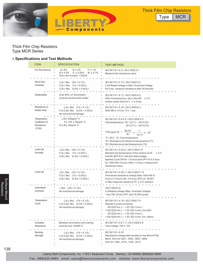
138
Surface M
ountS
urface Mount
Resistors
Resistors
Sur
face
Mou
ntR
esis
tors
Thick Film Chip ResistorsType MCR Series
∆ Specifications and Test MethodsITEM SPECIFICATION
DC Resistance J :± 5% G:± 2% F: ± 1%D:± 0.5% C: ± 0.25% B: ± 0.1%Zero ohm Jumper <50mΩ
TEST METHOD
Between termination and coatingmust be over 1000M Ω
InsulationResistance
IEC 60115-1 4.6.1.1 / JIS C 5202 5.6Test voltage: 100 ± 15V
J,G:∆ R≤± (1% + 0.1Ω ) F,D,C,B:∆ R≤± (0.5% + 0.05Ω ) No mechanical damage
BendingStrength
IEC 60115-1 4.33Resistance change after bended on the 90mm PCB.Bend: 3mm for 0201 , 0402 , 0603 , 08052mm for 1206 , 2010 , 1225 , 2512
IEC 60115-1 4.5 / JIS C 5202 5.1 Measure the resistance value.
J,G:∆ R≤± (2% + 0.1Ω ) F,D:∆ R≤± (1% + 0.05Ω ) C,B:∆ R≤± (0.5% + 0.05Ω )
Short time Overload
IEC 60115-1 4.13 / JIS C 5202 5.52.5X Rated voltage or Max. Overload Voltage for 5 sec. measure resistance after 30 minutes
Over 95% of terminationmust be covered with solder
Solderability IEC 60115-1 4.17 / JIS C 5202 6.5 After immersing flux, dip in the 245 ± 2˚C molten solder bath for 3 ± 0.5 sec.
J,G:∆ R≤± (1% + 0.1Ω ) F,D,C,B:∆ R≤± (0.5% + 0.05Ω )No mechanical damage
Resistance toSolder Heat
IEC 60115-1 4.18 / JIS C 5202 6.4 With 260 ± 5˚C for 10 ± 1 sec.
J,G:∆ R≤± (3% + 0.1Ω ) F,D:∆ R≤± (1% + 0.05Ω ) C,B:∆ R≤± (0.5% + 0.05Ω )
Load LifeHumidity
IEC 60115-1 4.24.2 / JIS C 5202 7.9 Maintain the temperature of the resistor at 40 ± 2˚C and 90~95% R.H. with the rated voltage applied.Cycle ON for 1.5 hours and OFF for 0.5 hour for 1000+48/-0 hours. After 1~4 hour, measure the resistance value.
J,G:∆ R≤± (3% + 0.1Ω ) F,D:∆ R≤± (1% + 0.05Ω ) C,B:∆ R≤± (0.5% + 0.05Ω )
Load Life IEC 60115-1 4.25.1 / JIS C 5202 7.10 Permanent resistance change after 1000+48/-0 hours (1.5 hours ON , 0.5 hour OFF) at RCWV or Max.Keep the resistor at 70 ± 2˚C ambient
∆ R≤± (5% + 0.1Ω ) No mechanical damage
IntermittentOverload
JIS C 5202 5.8 4.0xRated voltage (Max. Overload Voltage) 1 sec ON, 25 sec OFF, test 10,000 cycles
J,G:∆ R≤± (1% + 0.1Ω ) F,D,C,B:∆ R≤± (0.5% + 0.05Ω ) No mechanical damage
TemperatureCycle
IEC 60115-1 4.19 / JIS C 5202 7.4 Repeat 5 cycles as follows -55˚C(30 min.) ~ + 25 ˚C(2~3 min.) +125˚C(30 min.) ~ + 25 ˚C(2~3 min.) for 0201 -55˚C(30 min.) ~ + 25 ˚C(2~3 min.) +155˚C(30 min.) ~ + 25 ˚C(2~3 min.) for others
J,G:± 200ppm/ ˚C F:± 100 ± 50ppm/ ˚CD,C,B:± 50ppm/ ˚C
TemperatureCoefficient of Resistance (TCR)
IEC 60115-1 4.8.4.2 / JIS C 5202 5.2 Test temperature : 25 ˚C (T1)→ -55˚C (T2) 25˚C (T1)→ 125˚C (T2)
TCR (ppm/̊ C) = R2-R1R1
x xT2-T1
1106
T1: 25˚C T2: Test temperatureR1: Resistance at reference temperature (T1)R2: Resistance at test temperature (T2)
Type MCRThick Film Chip Resistors
Liberty Bell Components, Inc. 11631 Seaboard Circle, Stanton, CA 90680 (888)820-8885Fax: (888)820-8884 email: [email protected] website: www.libertycomponents.com

139
Surface M
ountR
esistors
Sur
face
Mou
ntS
urfa
ce M
ount
Res
isto
rsR
esis
tors
Thick Film Chip ResistorsType MCR Series - Low Resistance
∆ Specifications and Test Methods
ITEM SPECIFICATION
DC Resistance J :± 5%, F: ±1%
J:∆ R≤± (2% + 0.5m Ω ) F:∆ R≤± (1% + 0.5m Ω )
J:∆ R≤± (3% + 0.5m Ω ) F:∆ R≤± (1% + 0.5m Ω )
J:∆ R≤± (3% + 0.5m Ω ) F:∆ R≤± (1% + 0.5m Ω )
J:∆ R≤± (1% + 0.5m Ω ) F:∆ R≤± (0.5% + 0.5m Ω )No mechanical damage
J:∆ R≤± (1% + 1m Ω ) F:∆ R≤± (0.5% +1m Ω )No mechanical damage
J:∆ R≤± (1% + 1m Ω ) F:∆ R≤± (0.5% +1m Ω )No mechanical damage
Size : 0603 , 0805 100mΩ ~ 910mΩ :± 300ppm/ ˚CSize : 1206 , 2010 , 2512 50mΩ ~ 910mΩ :± 200ppm/ ˚CSize : 1225 20mΩ ~ 910mΩ :± 100ppm/ ˚C
Over 95% of terminationmust be covered with solder
TEST METHOD
Short time Overload
Solderability
Resistance toSolder Heat
Load LifeHumidity
Load Life
TemperatureCycle
InsulationResistance
BendingStrength
TemperatureCoefficient of Resistance (TCR)
referance for other resistance range in page 4
Between termination and coatingmust be over 1000M Ω
IEC 60115-1 4.6.1.1 / JIS C 5202 5.6Test voltage: 100 ± 15V
IEC 60115-1 4.33Resistance change after bended on the 90mm PCB.Bend: 3mm for 0201 , 0402 , 0603 , 08052mm for 1206 , 2010 , 1225 , 2512
IEC 60115-1 4.5 / JIS C 5202 5.1 Measure the resistance value.
IEC 60115-1 4.13 / JIS C 5202 5.52.5X Rated voltage or Max. Overload Voltage for 5 sec. measure resistance after 30 minutes
IEC 60115-1 4.17 / JIS C 5202 6.5 After immersing flux, dip in the 245 ± 2 ˚C molten solder bath for 3 ± 0.5 sec.
IEC 60115-1 4.18 / JIS C 5202 6.4 With 260 ± 5˚C for 10 ± 1 sec.
IEC 60115-1 4.24.2 / JIS C 5202 7.9 Maintain the temperature of the resistor at 40 ± 2 ˚C and 90~95% R.H. with the rated voltage applied.Cycle ON for 1.5 hours and OFF for 0.5 hour for 1000+48/-0 hours. After 1~4 hour, measure the resistance value.
IEC 60115-1 4.25.1 / JIS C 5202 7.10 Permanent resistance change after 1000+48/-0 hours (1.5 hours ON , 0.5 hour OFF) at RCWV or Max.Keep the resistor at 70 ± 2˚C ambient
IEC 60115-1 4.8.4.2 / JIS C 5202 5.2 Test temperature : 25 ˚C (T1)→ -55˚C (T2) 25˚C (T1)→ -125˚C (T2)
TCR (ppm/̊ C) = R2-R1R1
x xT2-T1
1106
T1: 25˚C T2: Test temperatureR1: Resistance at reference temperature (T1)R2: Resistance at test temperature (T2)
IEC 60115-1 4.19 / JIS C 5202 7.4 Repeat 5 cycles as follows -55˚C(30 min.) ~ + 25 ˚C(2~3 min.) +125˚C(30 min.) ~ + 25 ˚C(2~3 min.) for 0201 -55˚C(30 min.) ~ + 25 ˚C(2~3 min.) +155˚C(30 min.) ~ + 25 ˚C(2~3 min.) for others
Type MCRThick Film Chip Resistors
Liberty Bell Components, Inc. 11631 Seaboard Circle, Stanton, CA 90680 (888)820-8885Fax: (888)820-8884 email: [email protected] website: www.libertycomponents.com
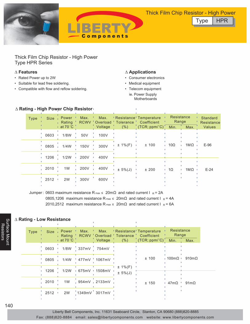
140
Surface M
ountS
urface Mount
Resistors
Resistors
Sur
face
Mou
ntR
esis
tors
Thick Film Chip Resistor - High PowerType HPR Series
• Rated Power up to 2W• Suitable for lead free soldering.• Compatible with flow and reflow soldering.
∆ Features ∆ Applications• Consumer electronics• Medical equipment• Telecom equipment ie. Power Supply Motherboards
∆ Rating - High Power Chip Resistor
∆ Rating - Low Resistance
0603 maximum resistance R max ≤ 20mΩ and rated current I R = 2A 0805,1206 maximum resistance R max ≤ 20mΩ and rated current I R = 4A 2010,2512 maximum resistance R max ≤ 20mΩ and rated current I R = 6A
Jumper :
Type Size
0603
0805
1206
2010
2512
Power Ratingat 70 ˚C
1/8W
1/4W
1/2W
1W
2W
Max.RCWV
50V
150V
200V
200V
300V
Max. OverloadVoltage
100V
300V
400V
400V
600V
10Ω
1Ω
1MΩ
1MΩ
E-96
E-24
± 1%(F)
Resistance Tolerance
(%)
Temperature Coefficient
(TCR; ppm/˚C )
ResistanceRange
Min. Max.
± 100
± 200
Standard Resistance
Values
± 5%(J)
Type Size
0603
0805
1206
2010
2512
Power Ratingat 70 ˚C
1/8W
1/4W
1/2W
1W
2W
Max.RCWV
337mV
477mV
675mV
954mV
1349mV
Max. OverloadVoltage
754mV
1067mV
1508mV
2133mV
3017mV
100mΩ
47mΩ
910mΩ
91mΩ
± 1%(F)
Resistance Tolerance
(%)
Temperature Coefficient
(TCR; ppm/˚C )
ResistanceRange
Min. Max.
± 100
± 150
± 5%(J)
Type HPRThick Film Chip Resistor - High Power
Liberty Bell Components, Inc. 11631 Seaboard Circle, Stanton, CA 90680 (888)820-8885Fax: (888)820-8884 email: [email protected] website: www.libertycomponents.com

141
Surface M
ountR
esistors
Sur
face
Mou
ntS
urfa
ce M
ount
Res
isto
rsR
esis
tors
Thick Film Chip Resistor - High PowerType HPR Series
Part Number
E-24 Series E-96 Series
∆ How to Order
∆ Resistance Marking
473 1542 0C2
ex. 473: 47x10^3 = 47KΩ105: 10x10^5 = 1MΩ1R5: 15x10^-1 = 1.5Ω
0: 0Ω
3 digit marking for E24
1R00
ex. 1R00: 1ΩR470 470mΩR010 10mΩ
4 digit marking for E241: Ω~10mΩex. 1542: 154x10^2 = 15K4Ω
4 digit marking for E96ex. 0C2 (see table)
102x10^2 = 10K2Ω
3 digit marking for E96 - 0603
example HPR 0603Type SizeHPR 0603 T: Tape F: ±1% 123 = 12x10^3 LF = Lead Free
0805 J: ±5% = 12k Ω120620102512
LF123Resistance ValuePacking Tolerance
T J
Type HPRThick Film Chip Resistor - High Power
Liberty Bell Components, Inc. 11631 Seaboard Circle, Stanton, CA 90680 (888)820-8885Fax: (888)820-8884 email: [email protected] website: www.libertycomponents.com

142
Surface M
ountS
urface Mount
Resistors
Resistors
Sur
face
Mou
ntR
esis
tors
Thick Film Chip Resistor - High PowerType HPR Series
∆ Specifications and Test Methods
ITEM SPECIFICATION
DC Resistance J :± 5% , F: ± 1%
J:∆ R≤± (2% + 0.1Ω ) F:∆ R≤± (1% + 0.05Ω )
J: ± 150 ppm/ ˚C F: ± 100 ppm/ ˚C
J:∆ R≤± (3% + 0.1Ω ) F:∆ R≤± (1% + 0.05Ω )
J:∆ R≤± (3% + 0.1Ω ) F:∆ R≤± (1% + 0.05Ω )
J:∆ R≤± (1% + 0.1Ω ) F:∆ R≤± (0.5% + 0.05Ω )No mechanical damage
J:∆ R≤± (1% + 0.1Ω ) F:∆ R≤± (0.5% +0.05Ω )No mechanical damage
J:∆ R≤± (1% + 0.1Ω ) F:∆ R≤± (0.5% +0.05Ω )No mechanical damage
Over 95% of terminationmust be covered with solder
TEST METHOD
Short time Overload
Solderability
Resistance toSolder Heat
Load LifeHumidity
Load Life
TemperatureCycle
InsulationResistance
BendingStrength
TemperatureCoefficient of Resistance (TCR)
Between termination and coatingmust be over 1000M Ω
IEC 60115-1 4.6.1.1 / JIS C 5202 5.6Test voltage: 100 ± 15V
IEC 60115-1 4.33Resistance change after bended on the 90mm PCB.Bend: 3mm for 0603 , 08052mm for 1206 , 2010 , 2512
IEC 60115-1 4.5 / JIS C 5202 5.1 Measure the resistance value.
IEC 60115-1 4.13 / JIS C 5202 5.55 X Rated voltage or Max. Overload Voltage for 5 sec. measure resistance after 30 minutes
IEC 60115-1 4.17 / JIS C 5202 6.5 After immersing flux, dip in the 245 ± 2 ˚Cmolten solder bath for 3 ± 0.5 sec.
IEC 60115-1 4.18 / JIS C 5202 6.4 With 260 ± 5˚C for 10 ± 1 sec.
IEC 60115-1 4.24.2 / JIS C 5202 7.9 Maintain the temperature of the resistor at 40 ± 2 ˚Cand 90~95% R.H. with the rated voltage applied.Cycle ON for 1.5 hours and OFF for 0.5 hour for 1000+48/-0 hours. After 1~4 hour, measure the resistance value.
IEC 60115-1 4.25.1 / JIS C 5202 7.10 Permanent resistance change after 1000+48/-0 hours (1.5 hours ON , 0.5 hour OFF) at RCWV or Max.Keep the resistor at 70 ± 2˚C ambient
IEC 60115-1 4.8.4.2 / JIS C 5202 5.2 Test temperature : 25 ˚C (T1)→ -55˚C (T2) 25˚C (T1)→ 125˚C (T2)
TCR (ppm/̊ C) = R2-R1R1
x xT2-T1
1106
T1: 25˚C T2: Test temperatureR1: Resistance at reference temperature (T1)R2: Resistance at test temperature (T2)
IEC 60115-1 4.19 / JIS C 5202 7.4 Repeat 5 cycles as follows -55˚C(30 min.) ~ + 25 ˚C(2~3 min.) +125˚C(30 min.) ~ + 25 ˚C(2~3 min.)
Type HPRThick Film Chip Resistor - High Power
Liberty Bell Components, Inc. 11631 Seaboard Circle, Stanton, CA 90680 (888)820-8885Fax: (888)820-8884 email: [email protected] website: www.libertycomponents.com
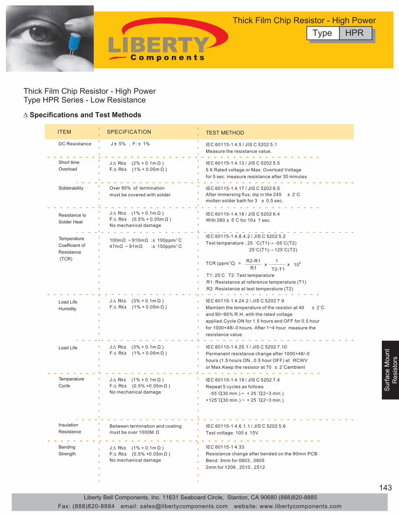
143
Surface M
ountR
esistors
Sur
face
Mou
ntS
urfa
ce M
ount
Res
isto
rsR
esis
tors
Thick Film Chip Resistor - High PowerType HPR Series - Low Resistance
∆ Specifications and Test Methods
ITEM SPECIFICATION
DC Resistance J :± 5% , F: ± 1%
J:∆ R≤± (2% + 0.1m Ω ) F:∆ R≤± (1% + 0.05m Ω )
J:∆ R≤± (3% + 0.1m Ω ) F:∆ R≤± (1% + 0.05m Ω )
J:∆ R≤± (3% + 0.1m Ω ) F:∆ R≤± (1% + 0.05m Ω )
J:∆ R≤± (1% + 0.1m Ω ) F:∆ R≤± (0.5% + 0.05m Ω )No mechanical damage
J:∆ R≤± (1% + 0.1m Ω ) F:∆ R≤± (0.5% +0.05m Ω )No mechanical damage
J:∆ R≤± (1% + 0.1m Ω ) F:∆ R≤± (0.5% +0.05m Ω )No mechanical damage
100mΩ ~ 910mΩ :± 100ppm/˚C47mΩ ~ 91mΩ :± 150ppm/˚C
Over 95% of terminationmust be covered with solder
TEST METHOD
Short time Overload
Solderability
Resistance toSolder Heat
Load LifeHumidity
Load Life
TemperatureCycle
InsulationResistance
BendingStrength
TemperatureCoefficient of Resistance (TCR)
Between termination and coatingmust be over 1000M Ω
IEC 60115-1 4.6.1.1 / JIS C 5202 5.6Test voltage: 100 ± 15V
IEC 60115-1 4.33Resistance change after bended on the 90mm PCB.Bend: 3mm for 0603 , 08052mm for 1206 , 2010 , 2512
IEC 60115-1 4.5 / JIS C 5202 5.1 Measure the resistance value.
IEC 60115-1 4.13 / JIS C 5202 5.55 X Rated voltage or Max. Overload Voltage for 5 sec. measure resistance after 30 minutes
IEC 60115-1 4.17 / JIS C 5202 6.5 After immersing flux, dip in the 245 ± 2˚C molten solder bath for 3 ± 0.5 sec.
IEC 60115-1 4.18 / JIS C 5202 6.4 With 260 ± 5˚C for 10± 1 sec.
IEC 60115-1 4.24.2 / JIS C 5202 7.9 Maintain the temperature of the resistor at 40 ± 2˚C and 90~95% R.H. with the rated voltage applied.Cycle ON for 1.5 hours and OFF for 0.5 hour for 1000+48/-0 hours. After 1~4 hour, measure the resistance value.
IEC 60115-1 4.25.1 / JIS C 5202 7.10 Permanent resistance change after 1000+48/-0 hours (1.5 hours ON , 0.5 hour OFF) at RCWV or Max.Keep the resistor at 70 ± 2˚C ambient
IEC 60115-1 4.8.4.2 / JIS C 5202 5.2 Test temperature : 25 ˚C (T1)→ -55˚C (T2) 25˚C (T1)→ 125˚C (T2)
TCR (ppm/̊ C) = R2-R1R1
x xT2-T1
1106
T1: 25˚C T2: Test temperatureR1: Resistance at reference temperature (T1)R2: Resistance at test temperature (T2)
IEC 60115-1 4.19 / JIS C 5202 7.4 Repeat 5 cycles as follows -55˚C(30 min.) ~ + 25 ˚C(2~3 min.) +125˚C(30 min.) ~ + 25 ˚C(2~3 min.)
Type HPRThick Film Chip Resistor - High Power
Liberty Bell Components, Inc. 11631 Seaboard Circle, Stanton, CA 90680 (888)820-8885Fax: (888)820-8884 email: [email protected] website: www.libertycomponents.com

144
Surface M
ountS
urface Mount
Resistors
Resistors
Sur
face
Mou
ntR
esis
tors
Thick Film Chip Resistor - TrimmableType TCR Series
• Resistance and protection film designed for YAG Laser Trimming• Available for fine tuning of the resistance value to obtain optimal circuit signals.• Suitable for lead free soldering.
∆ Features ∆ Applications• Tuner• Mobile Phone• Smoke Detector• Portable Measuring Equipment• Photo Sensor
∆ Resistance Rising Rate
• Compatible with flow and reflow soldering.
Single cutL cut
Double cut
Initial resistance increase of magnification
1.5
2
0.5 11
0
�R
/R M
agni
ficat
ion
Doublereverse cut
W'/W (W'= Tota l trimmed length) W' W
Trimming shall be performed by laser.The maxium rising resistance equals to two times of the initial and the differences will depend on trimming type as shown at the left.
Type Size
0603
0805
1206
2010
2512
Power Ratingat 70 ˚C
1/10W
1/8W
1/4W
1/2W
1W
Max.RCWV
50V
150V
200V
200V
200V
Max. OverloadVoltage
100V
300V
400V
400V
400V
100Ω 1M Ω E-240~ -30%(X)
0~ -20%(Y)
Resistance Tolerance
(%)
Temperature Coefficient
(TCR; ppm/ ˚C )
ResistanceRange
Min. Max.
± 100
Standard Resistance
Values
∆ Rating
example TCR 0603Type SizeTCR 0603 T: Tape X: 0%~-30% 123 = 12x10^3 LF = Lead Free
0805 Y: 0%~-20% = 12k Ω120620102512
LF123Resistance ValuePacking Tolerance
T XPart Number∆ How to Order
Type TCRThick Film Chip Resistor - Trimmable
Liberty Bell Components, Inc. 11631 Seaboard Circle, Stanton, CA 90680 (888)820-8885Fax: (888)820-8884 email: [email protected] website: www.libertycomponents.com

145
Surface M
ountR
esistors
Sur
face
Mou
ntS
urfa
ce M
ount
Res
isto
rsR
esis
tors
Thick Film Chip Resistor - TrimmableType TCR Series
∆ Specifications and Test Methods
ITEM SPECIFICATION
DC Resistance X :0~ -30% , Y :0~ -20%
∆ R≤± (2% + 0.1Ω )
∆ R≤± (3% + 0.1Ω )
∆ R≤± (3% + 0.1Ω )
∆ R≤± (5% + 0.1Ω )No mechanical damage
∆ R≤± (1% + 0.1Ω )No mechanical damage
∆ R≤± (1% + 0.1Ω )No mechanical damage
∆ R≤± (1% + 0.1Ω ) No mechanical damage
± 100ppm/ ˚C
Over 95% of terminationmust be covered with solder
TEST METHOD
Short time Overload
Solderability
Resistance toSolder Heat
Load LifeHumidity
Load Life
TemperatureCycle
InsulationResistance
Intermittent Overload
BendingStrength
TemperatureCoefficient of Resistance (TCR)
Between termination and coatingmust be over 1000M Ω
IEC 60115-1 4.6.1.1 / JIS C 5202 5.6Test voltage: 100 ± 15V
IEC 60115-1 4.33Resistance change after bended on the 90mm PCB.Bend: 3mm for 0603 , 08052mm for 1206 , 2010 , 2512
IEC 60115-1 4.5 / JIS C 5202 5.1 Measure the resistance value.
IEC 60115-1 4.13 / JIS C 5202 5.52.5X Rated voltage or Max. Overload Voltage for 5 sec. measure resistance after 30 minutes
IEC 60115-1 4.17 / JIS C 5202 6.5 After immersing flux, dip in the 245 ± 2 ˚C molten solder bath for 3 ± 0.5 sec.
IEC 60115-1 4.18 / JIS C 5202 6.4 With 260 ± 5˚C for 10 ± 1 sec.
IEC 60115-1 4.24.2 / JIS C 5202 7.9 Maintain the temperature of the resistor at 40 ± 2 ˚C and 90~95% R.H. with the rated voltage applied.Cycle ON for 1.5 hours and OFF for 0.5 hour for 1000+48/-0 hours. After 1~4 hour, measure the resistance value.
IEC 60115-1 4.25.1 / JIS C 5202 7.10 Permanent resistance change after 1000+48/-0 hours (1.5 hours ON , 0.5 hour OFF) at RCWV or Max.Keep the resistor at 70 ± 2˚C ambient
IEC 60115-1 4.8.4.2 / JIS C 5202 5.2 Test temperature : 25 ˚C (T1)→ -55˚C (T2) 25˚C (T1)→ 125˚C (T2)
TCR (ppm/̊ C) = R2-R1R1
x xT2-T1
1106
T1: 25˚C T2: Test temperatureR1: Resistance at reference temperature (T1)R2: Resistance at test temperature (T2)
JIS C 5202 5.8 4.0 x Rated voltage (Max. Overload Voltage) 1 sec ON, 25 sec OFF, test 10,000 cycles
IEC 60115-1 4.19 / JIS C 5202 7.4 Repeat 5 cycles as follows -55˚C(30 min.) ~ + 25 ˚C(2~3 min.) +125˚C(30 min.) ~ + 25 ˚C(2~3 min.)
Type TCRThick Film Chip Resistor - Trimmable
Liberty Bell Components, Inc. 11631 Seaboard Circle, Stanton, CA 90680 (888)820-8885Fax: (888)820-8884 email: [email protected] website: www.libertycomponents.com

146
Surface M
ountS
urface Mount
Resistors
Resistors
Sur
face
Mou
ntR
esis
tors
Thick Film Chip Resistor - SurgeType SCR Series
• Suitable for withstanding circuit for surge voltage• Suitable for lead free soldering.
∆ Features ∆ Applications• Measurement Instrument• Power Supply
• Compatible with flow and reflow soldering.
∆ Rating
Part Number∆ How to Order
Type Size
0603
0805
1206
2010
2512
Power Ratingat 70 ˚C
1/10W
1/8W
1/4W
1/2W
1W
Max.RCWV
50V
150V
200V
200V
200V
Max. OverloadVoltage
100V
300V
400V
400V
400V
10Ω 1M Ω E-24
Resistance Tolerance
(%)
Temperature Coefficient
(TCR; ppm/ ˚C )
ResistanceRange
Min. Max.
± 100
± 5%(J)± 10%(K)±1 5%(L)± 20%(M)
Standard Resistance
Values
103
example SCR 0603Type SizeSCR 0603 T: Tape J: ±5% 123 = 12x10^3 LF = Lead Free
0805 K: ±10% = 12k Ω1206 L: ±15%2010 M: ±20%2512
LF123Resistance ValuePacking Tolerance
T J
E-24 Series
∆ Resistance Marking
473
ex. 473: 47x10^3 = 47KΩ105: 10x10^5 = 1MΩ1R5: 15x10^-1 = 1.5Ω
0: 0Ω
3 digit marking for E24
1R00
ex. 1R00: 1ΩR470 470mΩR010 10mΩ
4 digit marking for E241: Ω~10mΩ
Type SCRThick Film Chip Resistor - Surge
• Medical Equipment• Telecom Equipment• Consumer Electronics
• Automotive Industry
Liberty Bell Components, Inc. 11631 Seaboard Circle, Stanton, CA 90680 (888)820-8885Fax: (888)820-8884 email: [email protected] website: www.libertycomponents.com

147
Surface M
ountR
esistors
Sur
face
Mou
ntS
urfa
ce M
ount
Res
isto
rsR
esis
tors
Thick Film Chip Resistor - SurgeType SCR Series
∆ Specifications and Test Methods
ITEM SPECIFICATION
DC Resistance J :± 5% K : ± 10%L :±1 5% M : ± 20%
∆ R≤± (2% + 0.1Ω )
∆ R≤± (1% + 0.1Ω )
∆ R≤± (3% + 0.1Ω )
∆ R≤± (3% + 0.1Ω )
∆ R≤± (5% + 0.1Ω ) No mechanical damage
± 100 ppm/ ˚C
∆ R≤± (1% + 0.1Ω ) No mechanical damage
∆ R≤± (1% + 0.1Ω ) No mechanical damage
∆ R≤± (1% + 0.1Ω ) No mechanical damage
Over 95% of terminationmust be covered with solder
TEST METHOD
Short time Overload
High VoltagePulses
Solderability
Resistance toSolder Heat
Load LifeHumidity
Load Life
IntermittentOverload
TemperatureCycle
InsulationResistance
BendingStrength
TemperatureCoefficient of Resistance (TCR)
Between termination and coatingmust be over 1000M Ω
IEC 60115-1 4.6.1.1 / JIS C 5202 5.6Test voltage: 100 ± 15V
IEC 60115-1 4.33Resistance change after bended on the 90mm PCB.Bend: 3mm for 0603 , 08052mm for 1206 , 2010 , 2512
IEC 60115-1 4.5 / JIS C 5202 5.1 Measure the resistance value.
IEC 60115-1 4.13 / JIS C 5202 5.52.5X Rated voltage or Max. Overload Voltage for 5 sec. measure resistance after 30 minutes
IEC 60115-1 4.17 / JIS C 5202 6.5 After immersing flux, dip in the 245 ± 2 ˚C molten solder bath for 3 ± 0.5 sec.
IEC 801-5 1.2/50μ s 2kV 100 Pulses (Sequence 25 P /min)
IEC 60115-1 4.18 / JIS C 5202 6.4 With 260 ± 5˚C for 10 ± 1 sec.
IEC 60115-1 4.24.2 / JIS C 5202 7.9 Maintain the temperature of the resistor at 40 ± 2 ˚C and 90~95% R.H. with the rated voltage applied.Cycle ON for 1.5 hours and OFF for 0.5 hour for 1000+48/-0 hours. After 1~4 hour, measure the resistance value.
IEC 60115-1 4.25.1 / JIS C 5202 7.10 Permanent resistance change after 1000+48/-0 hours (1.5 hours ON , 0.5 hour OFF) at RCWV or Max.Keep the resistor at 70 ± 2˚C ambient
JIS C 5202 5.8 4.0 x Rated voltage (Max. Overload Voltage) 1 sec ON, 25 sec OFF, test 10,000 cycles
IEC 60115-1 4.8.4.2 / JIS C 5202 5.2 Test temperature : 25 ˚C (T1)→ -55˚C (T2) 25˚C (T1)→ 125˚C (T2)
TCR (ppm/̊ C) = R2-R1R1
x xT2-T1
1106
T1: 25˚C T2: Test temperatureR1: Resistance at reference temperature (T1)R2: Resistance at test temperature (T2)
IEC 60115-1 4.19 / JIS C 5202 7.4 Repeat 5 cycles as follows -55˚C(30 min.) ~ + 25 ˚C(2~3 min.) +125˚C(30 min.) ~ + 25 ˚C(2~3 min.)
Type SCRThick Film Chip Resistor - Surge
Liberty Bell Components, Inc. 11631 Seaboard Circle, Stanton, CA 90680 (888)820-8885Fax: (888)820-8884 email: [email protected] website: www.libertycomponents.com

148
Surface M
ountS
urface Mount
Resistors
Resistors
Sur
face
Mou
ntR
esis
tors
Thick Film Chip Resistor - High VoltageType HVR Series
• Special material and design for high working voltage requirement
• Suitable for lead free soldering.
∆ Features ∆ Applications
• Power Supply• Automotive Industry
• Compatible with flow and reflow soldering.
∆ Rating
Part Number∆ How to Order
E-24 Series
∆ Resistance Marking
473
ex. 473: 47x10^3 = 47KΩ105: 10x10^5 = 1MΩ1R5: 15x10^-1 = 1.5Ω
0: 0Ω
3 digit marking for E24
1R00
ex. 1R00: 1ΩR470 470mΩR010 10mΩ
4 digit marking for E241: Ω~10mΩ
Type Size
1206
2010
2512
Power Ratingat 70 ˚C
1/4W
1/2W
1W
Max.RCWV
800V
1500V
2000V
Max. OverloadVoltage
1600V
3000V
4000V
100KΩ 1MΩ E-24
Resistance Tolerance
(%)
Temperature Coefficient
(TCR; ppm/˚C )
ResistanceRange
Min. Max.
± 200± 5%(J)
Standard Resistance
Values
example HVR 1206Type SizeHVR 1206 T: Tape J: ±5% 123 = 12x10^3 LF = Lead Free
2010 = 12k Ω2512
LF123Resistance ValuePacking Tolerance
T J
Type HVRThick Film Chip Resistor - High Voltage
• Medical Equipment• Telecom Equipment• Consumer Electronics
Liberty Bell Components, Inc. 11631 Seaboard Circle, Stanton, CA 90680 (888)820-8885Fax: (888)820-8884 email: [email protected] website: www.libertycomponents.com
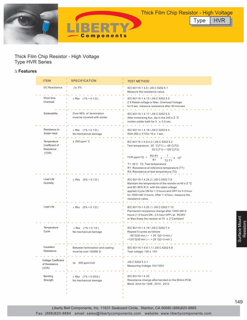
149
Surface M
ountR
esistors
Sur
face
Mou
ntS
urfa
ce M
ount
Res
isto
rsR
esis
tors
Thick Film Chip Resistor - High VoltageType HVR Series
∆ Features
ITEM SPECIFICATION
DC Resistance J :± 5%
∆ R≤± (1% + 0.1Ω )
∆ R≤± (5% + 0.1Ω )
∆ R≤± (5% + 0.1Ω )
≤± 300 ppm/Volt
± 200 ppm/ ˚C
∆ R≤± (1% + 0.1Ω ) No mechanical damage
∆ R≤± (1% + 0.1Ω ) No mechanical damage
∆ R≤± (1% + 0.05Ω ) No mechanical damage
Over 95% of terminationmust be covered with solder
TEST METHOD
Short time Overload
Solderability
Resistance toSolder Heat
Load LifeHumidity
Load Life
TemperatureCycle
InsulationResistance
BendingStrength
TemperatureCoefficient of Resistance (TCR)
Between termination and coatingmust be over 1000M Ω
IEC 60115-1 4.6.1.1 / JIS C 5202 5.6Test voltage: 100 ± 15V
JIS C 5202 5.3.1 Measuring Voltage 10V/100V
IEC 60115-1 4.33Resistance change after bended on the 90mm PCB.Bend: 2mm for 1206 , 2010 , 2512
IEC 60115-1 4.5 / JIS C 5202 5.1 Measure the resistance value.
IEC 60115-1 4.13 / JIS C 5202 5.52 X Rated voltage or Max. Overload Voltage for 5 sec. measure resistance after 30 minutes
IEC 60115-1 4.17 / JIS C 5202 6.5 After immersing flux, dip in the 245 ± 2 ˚C molten solder bath for 3 ± 0.5 sec.
IEC 60115-1 4.18 / JIS C 5202 6.4 With 260 ± 5˚C for 10 ± 1 sec.
IEC 60115-1 4.24.2 / JIS C 5202 7.9 Maintain the temperature of the resistor at 40 ± 2 ˚C and 90~95% R.H. with the rated voltage applied.Cycle ON for 1.5 hours and OFF for 0.5 hour for 1000+48/-0 hours. After 1~4 hour, measure the resistance value.
IEC 60115-1 4.25.1 / JIS C 5202 7.10 Permanent resistance change after 1000+48/-0 hours (1.5 hours ON , 0.5 hour OFF) at RCWV or Max.Keep the resistor at 70 ± 2˚C ambient
IEC 60115-1 4.8.4.2 / JIS C 5202 5.2 Test temperature : 25 ˚C (T1)→ -55˚C (T2) 25˚C (T1)→ 125˚C (T2)
TCR (ppm/̊ C) = R2-R1R1
x xT2-T1
1106
T1: 25˚C T2: Test temperatureR1: Resistance at reference temperature (T1)R2: Resistance at test temperature (T2)
Voltage Coefficient of Resistance (VCR)
IEC 60115-1 4.19 / JIS C 5202 7.4 Repeat 5 cycles as follows -55˚C(30 min.) ~ + 25 ˚C(2~3 min.) +125˚C(30 min.) ~ + 25 ˚C(2~3 min.)
Type HVRThick Film Chip Resistor - High Voltage
Liberty Bell Components, Inc. 11631 Seaboard Circle, Stanton, CA 90680 (888)820-8885Fax: (888)820-8884 email: [email protected] website: www.libertycomponents.com

150
Surface M
ountS
urface Mount
Resistors
Resistors
Sur
face
Mou
ntR
esis
tors
Thick Film Chip Resistor - High ResistanceType HRR Series
• Small size and lightweight with size range per International standard.• Highly stable in auto-replacement surface mounting application.
∆ Features ∆ Applications• Power Supply in small size
• Automotive Industry
• Compatible with flow and reflow soldering.
∆ Rating
Part Number∆ How to Order
Type Size
0603
0805
1206
Power Ratingat 70 ˚C
1/10W
1/8W
1/4W
Max.RCWV
50V
150V
200V
Max. OverloadVoltage
100V
300V
400V
11MΩ 100MΩ E-12
Resistance Tolerance
(%)
Temperature Coefficient
(TCR; ppm/˚C )
ResistanceRange
Min. Max.
± 200± 5%(J)
Standard Resistance
Values
• Battery Charger
example HRR 0603Type SizeHrr 0603 T: Tape J: ±5% 506 = 50x10^6 LF = Lead Free
0805 = 50M Ω1206
LF506Resistance ValuePacking Tolerance
T J
Type HRRThick Film Chip Resistor - High Resistance
• Medical Equipment• Telecom Equipment• Consumer Electronics
Liberty Bell Components, Inc. 11631 Seaboard Circle, Stanton, CA 90680 (888)820-8885Fax: (888)820-8884 email: [email protected] website: www.libertycomponents.com

151
Surface M
ountR
esistors
Sur
face
Mou
ntS
urfa
ce M
ount
Res
isto
rsR
esis
tors
Thick Film Chip Resistor - High ResistanceType HRR Series
∆ Features
ITEM SPECIFICATION
DC Resistance J :± 5%
J :∆ R≤± 2%
J :∆ R≤± 5%
J :∆ R≤± 5%
J : ± 200 ppm/ ˚C
J :∆ R≤± 2%
Over 95% of terminationmust be covered with solder
TEST METHOD
Short time Overload
Solderability
Resistance toSolder Heat
Load LifeHumidity
Load Life
TemperatureCoefficient of Resistance (TCR)
InsulationResistance
Between termination and coatingmust be over 1000M Ω
IEC 60115-1 4.6.1.1 / JIS C 5202 5.6Test voltage: 100 ± 15V
J :∆ R≤± 2%BendingStrength
IEC 60115-1 4.33Resistance change after bended on the 90mm PCB.Bend: 3mm for 0603 ,0805 ,2mm for 1206
IEC 60115-1 4.5 / JIS C 5202 5.1 Measure the resistance value.
IEC 60115-1 4.13 / JIS C 5202 5.52.5 X Rated voltage or Max. Overload Voltage for 5 sec. measure resistance after 30 minutes
IEC 60115-1 4.17 / JIS C 5202 6.5 After immersing flux, dip in the 245 ± 2 ˚Cmolten solder bath for 3 ± 0.5 sec.
IEC 60115-1 4.18 / JIS C 5202 6.4 With 260 ± 5˚C for 10 ± 1 sec.
IEC 60115-1 4.24.2 / JIS C 5202 7.9 Maintain the temperature of the resistor at 40 ± 2 ˚C and 90~95% R.H. with the rated voltage applied.Cycle ON for 1.5 hours and OFF for 0.5 hour for 1000+48/-0 hours. After 1~4 hour, measure the resistance value.
IEC 60115-1 4.25.1 / JIS C 5202 7.10 Permanent resistance change after 1000+48/-0 hours (1.5 hours ON , 0.5 hour OFF) at RCWV or Max.Keep the resistor at 70 ± 2˚C ambient
J :∆ R≤± 5%TemperatureCycle
IEC 60115-1 4.8.4.2 / JIS C 5202 5.2 Test temperature : 25 ˚C (T1)→ -55˚C (T2) 25˚C (T1)→ 125˚C (T2)
TCR (ppm/̊ C) = R2-R1R1
x xT2-T1
1106
T1: 25˚C T2: Test temperatureR1: Resistance at reference temperature (T1)R2: Resistance at test temperature (T2)
≤± 300 ppm/Volt JIS C 5202 5.3.1 Measuring Voltage 10V/100V
Voltage Coefficient of Resistance (VCR)
IEC 60115-1 4.19 / JIS C 5202 7.4 Repeat 5 cycles as follows -55˚C(30 min.) ~ + 25 ˚C(2~3 min.) +125˚C(30 min.) ~ + 25 ˚C(2~3 min.)
Type HRRThick Film Chip Resistor - High Resistance
Liberty Bell Components, Inc. 11631 Seaboard Circle, Stanton, CA 90680 (888)820-8885Fax: (888)820-8884 email: [email protected] website: www.libertycomponents.com

152
Surface M
ountS
urface Mount
Resistors
Resistors
Sur
face
Mou
ntR
esis
tors
Thick Film Chip Resistor - Metal StripType MSR Series
• High power rating and low TCR.
• Low resistance and high precision (1%).
∆ Features ∆ Applications• Switching Power Supply• Power Amplifier
• Excellent reliability and reasonable cost.
∆ Dimension and Construction
• Inductance less than 1.0nH.
• Suitable for lead free soldering.
1 2 3 4
L
W
T
a
R0101
2 3
4
Type 1.Protective Coating
Resin
2.Resistive Element
Alloy Metal
3.Terminal
Copper
4.Outer Terminal
Tin Plating
Type
1m,2m
3m~25m
L
6.20+/-0.25
6.20+/-0.20
W
3.20+/-0.25
3.20+/-0.20
T
0.70+/-0.20
0.60+/-0.20
a
2.0+/-0.30
0.80+/-0.20
Operating Temperature Range: -55 to +170 deg.C
Ambient Temperature (deg.C)
120
100
80
60
40
20
0
-55 -40 0 40 80 120
70
160 170 200
∆ Power Derating Curve
Type MSRThick Film Chip Resistor - Metal Strip
• Medical Equipment• Telecom Equipment• Consumer Electronics
Liberty Bell Components, Inc. 11631 Seaboard Circle, Stanton, CA 90680 (888)820-8885Fax: (888)820-8884 email: [email protected] website: www.libertycomponents.com

153
Surface M
ountR
esistors
Sur
face
Mou
ntS
urfa
ce M
ount
Res
isto
rsR
esis
tors
Thick Film Chip Resistor - Metal StripType MSR Series
∆ Rating
Type
FMF25
Power Ratingat 70 ˚C
1W
2W
158mV
224mV
316mV
418mV
Max.RCWV
Max. OverloadVoltage
Resistance Tolerance
(%)
Temperature Coefficient
(TCR; ppm/˚C )
ResistanceRange
± 1%(F)
± 5%(J)
± 1%(F)
± 5%(J)
± 100
± 70
± 100
± 70
1,2,3,4,5
7,10,12,15,18,20,25
1,2,3,4,5
7,10,12,15,18,20,25
(mΩ)
Part Number∆ How to Order
example MSR 2512Type SizeMSR 2512 T: Tape F: ±1% 506 = 50x10^6 H: 1W LF = Lead Free
J: ±5% = 50M Ω J: 2W
LFD001Resistance ValuePacking Tolerance
T J HWattage
R001 = 1mΩ
∆ Resistance Marking
R001
For 1~2mΩ
R020
For 3~25mΩ
R020 = 20mΩ
Type MSRThick Film Chip Resistor - Metal Strip
Liberty Bell Components, Inc. 11631 Seaboard Circle, Stanton, CA 90680 (888)820-8885Fax: (888)820-8884 email: [email protected] website: www.libertycomponents.com

154
Surface M
ountS
urface Mount
Resistors
Resistors
Sur
face
Mou
ntR
esis
tors
Thick Film Chip Resistor - Metal StripType MSR Series
∆ Rating
ITEM SPECIFICATION
DC Resistance F:± 1% , J :± 5%
� R�±( 1%+0.5m Ω )
� R�±(1 %+0.5m Ω )
� R�±(1 %+0.5m Ω )
Over 95% of terminationmust be covered with solder
TEST METHOD
Short time Overload
Solderability
Resistance toSolder Heat
Load LifeHumidity
Load Life
TemperatureCoefficient of Resistance (TCR)
InsulationResistance
Between termination and coatingmust be over 1000M Ω
IEC 60115-1 4.6.1.1 / JIS C 5202 5.6Test voltage: 100 ± 15V
BendingStrength
IEC 60115-1 4.33Resistance change after bended on the 90mm PCB.Bend: 2mm
IEC 60115-1 4.5 / JIS C 5202 5.1 Measure the resistance value.
IEC 60115-1 4.13 / JIS C 5202 5.55 X Rated voltage for 5 sec. measure resistance after 30 minutes
IEC 60115-1 4.17 / JIS C 5202 6.5 After immersing flux, dip in the 245 ± 2 ˚C molten solder bath for 3 ± 0.5 sec.
IEC 60115-1 4.18 / JIS C 5202 6.4 With 260 ± 5˚C for 10 ± 1 sec.
IEC 60115-1 4.24.2 / JIS C 5202 7.9 Maintain the temperature of the resistor at 40 ± 2 ˚C and 90~95% R.H. with the rated voltage applied.Cycle ON for 1.5 hours and OFF for 0.5 hour for 1000+48/-0 hours. After 1~4 hour, measure the resistance value.
IEC 60115-1 4.25.1 / JIS C 5202 7.10 Permanent resistance change after 1000+48/-0 hours (1.5 hours ON , 0.5 hour OFF) at RCWV or Max.Keep the resistor at 70 ± 2˚C ambient
TemperatureCycle
IEC 60115-1 4.8.4.2 / JIS C 5202 5.2 Test temperature : 25 ˚C (T1)→ -55˚C (T2) 25˚C (T1)→ 125˚C (T2)
TCR (ppm/̊ C) = R2-R1R1
x xT2-T1
1106
T1: 25˚C T2: Test temperatureR1: Resistance at reference temperature (T1)R2: Resistance at test temperature (T2)
� R�± (1% + 0.5m Ω ) No mechanical damage
� R�± (1% + 0.5m Ω ) No mechanical damage
� R�± (1% + 0.5m Ω ) No mechanical damage
1mΩ~ 5mΩ : ±100 ppm/ ˚C7mΩ~2 5mΩ : ±70 ppm/ ˚C
IEC 60115-1 4.19 / JIS C 5202 7.4 Repeat 5 cycles as follows -55˚C(30 min.) ~ + 25 ˚C(2~3 min.) +125˚C(30 min.) ~ + 25 ˚C(2~3 min.)
Type MSRThick Film Chip Resistor - Metal Strip
Liberty Bell Components, Inc. 11631 Seaboard Circle, Stanton, CA 90680 (888)820-8885Fax: (888)820-8884 email: [email protected] website: www.libertycomponents.com

155
Surface M
ountR
esistors
Sur
face
Mou
ntS
urfa
ce M
ount
Res
isto
rsR
esis
tors
Chip Resistor Array Type RCA
∆ Features • Suitable for lead free soldering • compatible with flow and reflow soldering
∆ Applications • Automotive, Medical, and Telecom Industries
∆ Part NumberType Size Isolated Circuit Configuration Packaging Tolerance Resistor ValueRCA 1206 B 8 T J 103
Chip Size Isolated Circuit 8P/4R Taping Example ExampleJ=5% 102=1KΩF=1% 103=10KΩ
∆ Soldering Temperature Curve
Min. Max.
RCA 1206 8P4R 1/16W (Element) 50V 100V ±5%(J)±1%(F) ±200 0Ω,10Ω 1MΩ E-24
Standard Resistance
Values
·Lead Free Chip Resistor Array
Jumper: 8P4R size maximum resistance Rmax = 50mΩ and rated current IR = 1A
Resistance Range (Ω)Type SizePowerRatingat 70°C
Max. RCWV
Max. OverloadVoltage
ResistanceTolerance (%)
Temperature Coefficient
(TCR: ppm/°C)
∆ Rating
Type RCAChip Resistor Array
Liberty Bell Components, Inc. 11631 Seaboard Circle, Stanton, CA 90680 (888)820-8885Fax: (888)820-8884 email: [email protected] website: www.libertycomponents.com

156
Surface M
ountS
urface Mount
Resistors
Resistors
Sur
face
Mou
ntR
esis
tors
∆ Configuration
Inner Termination Layer: Ag, Pd/Ag MIddle Termination Layer: Nickel Outer Termination Layer: Solder
∆ Dimensions
∆ Circuit
Size L W T C D P b1 b2 8P4R 3.20±0.20 1.60±0.10 0.50±0.10 0.30±0.20 0.30±0.20 0.80±0.05 0.45±0.10 0.70±0.20
(unit: mm)
RCA1206
0
20
40
60
80
100
-55 -45 -35 -25 -15 -5 5 15 25 35 45 55 65 75 85 95 105 115 125
Temperature °C
Rat
ed L
oad
(%)
∆ Power Derating Curve
For resistors operated in ambient temperature over 70°C, Power rating shall be derated in accordance with the curve above.
∆ Product Category • Lead Free Chip Resistor Array (RCA1206) Convex
Type RCAChip Resistor Array
Liberty Bell Components, Inc. 11631 Seaboard Circle, Stanton, CA 90680 (888)820-8885Fax: (888)820-8884 email: [email protected] website: www.libertycomponents.com

157
Surface M
ountR
esistors
Sur
face
Mou
ntS
urfa
ce M
ount
Res
isto
rsR
esis
tors
∆ Product Category • Specification and Test Method
ITEM SPECIFICATION TEST METHOD
DC Resistance J : ± 5 % , F : ± 1 % Zero Ohm Jumper < 50 mΩ
IEC 115-1 4.5 / JIS C 5202 5.1 Measure the resistance value.
Short Time Overload
J : ∆R ≤ ± ( 2 % + 0 . 1 Ω ) F : ∆R ≤ ± ( 1 % + 0 . 05 Ω )
IEC 115-1 4.13 / JIS C 5202 5.5 2.5xRated voltage or Max. Overload Voltage for 5 sec. measure resistance after 30 minutes.
Solderability Over 95% of termination must be covered with solder
IEC 115-1 4.17 / JIS C 5202 6.5 After immersing flux , dip in the 245 ± 2 °C molten solder bath for 3 ± 0 . 5 sec .
Resistance to Solder Heat
J : ∆R ≤ ± ( 1 % + 0 . 1 Ω ) F : ∆R ≤ ± ( 0 . 5 % + 0 . 05 Ω ) No mechanical damage
IEC 115-1 4.18 / JIS C 5202 6.4 with 260 ± 5 °C for 10 ± 1 sec .
Temperature Coefficient of Resistance
(TCR)
± 200 ppm / °C
IEC 115-1 4.8.4.2 / JIS C 5202 5.2 Test Temperature : 25 °C ( T 1 ) → - 55 °C ( T 2 ) 25 °C ( T 1 ) → 125 °C ( T 2 ) TCR ( ppm / °C ) = ( R 2 - R 1 )/ R 1 ( T 2 - T 1 ) x 106
R1: Resistance at reference temperature (T1) R2: Resistance at test temperature (T2)
Load Life Humidity
J : ∆R ≤ ± ( 3 % + 0 . 1 Ω ) F : ∆R ≤ ± ( 1 % + 0 . 05 Ω )
IEC 115-1 4.24.2 / JIS C 5202 7.9 Maintain the temperature of the resistor at 40 ± 2 °C and 90~95% R.H. with the rated voltage applied. Cycle ON for 1.5 hours. After 1~4 hour, measure the resistance value.
Load Life J : ∆R ≤ ± ( 3 % + 0 . 1 Ω ) F : ∆R ≤ ± ( 1 % + 0 . 05 Ω )
IEC 115-1 4.25.1 / JIS C 5202 7.10 Permanent resistance change after 1000+48/-0 hours (1.5 hours ON, 0.5 hour OFF) at RCWV or MAX. Keep the resistor at 70 ± 2 °C ambient
Intermittent Overload
∆R ≤ ± ( 3 % + 0 . 1 Ω ) No mechanical damage
JIS C 5202 5.8 4.0xRated voltage (Max. Overload Voltage) 1 sec ON, 25 sec OFF, test 10,000 cycles
Temperature Cycle
J : ∆R ≤ ± ( 1 % + 0 . 1 Ω ) F : ∆R ≤ ± ( 0 . 5 % + 0 . 05 Ω ) No mechanical damage
IEC 115-1 4.19 / JIS C 5202 7.4 Repeat 5 cycles as follows - 55 °C ( 30 min ) + 25 °C ( 2 ~ 3 min ) + 125 °C ( 30 min ) + 25 °C ( 2 ~ 3 min )
Insulation Resistance Between termination and coating must be over 1000 MΩ
IEC 115-1 4.6.1.1 / JIS C 5202 5.6 Test voltage : 100 ± 15 V
Bending Strength J : ∆R ≤ ± ( 1 % + 0 . 1 Ω )
F : ∆R ≤ ± ( 0 . 5 % + 0 . 05 Ω ) No mechanical damage
IEC 115-1 4.33 Resistance change after bended on the 90mm PCB. Bend: 3min
Type RCAChip Resistor Array
Liberty Bell Components, Inc. 11631 Seaboard Circle, Stanton, CA 90680 (888)820-8885Fax: (888)820-8884 email: [email protected] website: www.libertycomponents.com

158
Surface M
ountS
urface Mount
Resistors
Resistors
Sur
face
Mou
ntR
esis
tors
Thick Film Chip Resistor
• MCR - Chip Resistor: General Purpose, Low Resistance• HPR - High Power Chip Resistor• TCR - Trimmable Chip Resistor
∆ Product Category
∆ Configuration
• SCR - Surge Chip Resistor• HVR - High Voltage Chip Resistor• HRR - High Resistance Chip Resistor
±±±
±±
±±±
±
±±±
±±
±±±
±
±±±
±±
±±±
±
±±±
±±
±±±
±
±±±
±±
±±±
±
Maximum dissipation in percentageof rated power as a function of theambient temperature for all sizesexcept 0201.
Maximum dissipation in percentageof rated power as a function of theambient temperature for 0201.
0
20
40
60
80
100
-55 0 70 125 155
Ambient Temperature(˚C)
Rot
ed P
ower
(%)
0
20
40
60
80
100
-55 0 70 125
Ambient Temperature(˚C)
Rot
ed P
ower
(%)
103L
W
D
T
CProtective coating Outer Termination
Layer: Solder
Middle TerminationLayer: Nickel
Inner TerminationLayer: Ag. Pd/Ag
Resistive Element(RuO2)High PurityAlumina Substrate
∆ Dimensions
∆ Power Derating Curve
HPR
Thick Film Chip Resistor
Liberty Bell Components, Inc. 11631 Seaboard Circle, Stanton, CA 90680 (888)820-8885Fax: (888)820-8884 email: [email protected] website: www.libertycomponents.com
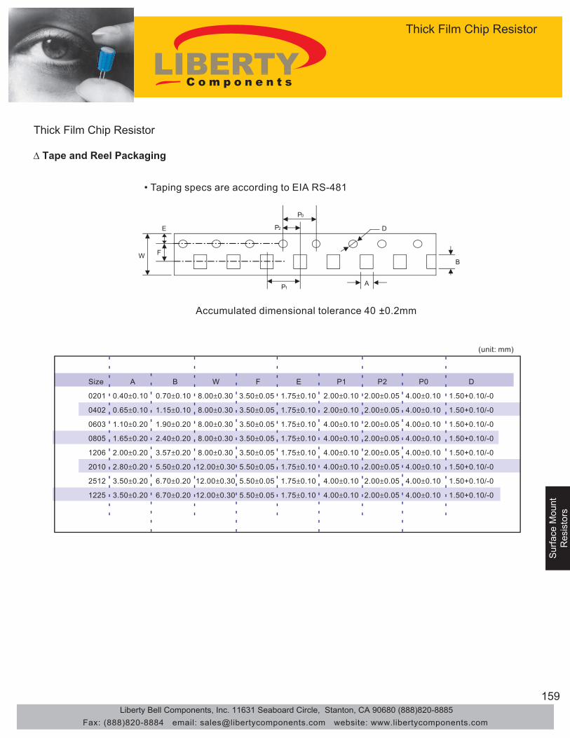
159
Surface M
ountR
esistors
Sur
face
Mou
ntS
urfa
ce M
ount
Res
isto
rsR
esis
tors
Thick Film Chip Resistor
∆ Tape and Reel Packaging
W
E P2 D
B
AP1
P0
F
Accumulated dimensional tolerance 40 ±0.2mm
• Taping specs are according to EIA RS-481
(unit: mm)
Size
0201
0402
0603
0805
1206
2010
2512
1225
A
0.40±0.10
0.65±0.10
1.10±0.20
1.65±0.20
2.00±0.20
2.80±0.20
3.50±0.20
3.50±0.20
B
0.70±0.10
1.15±0.10
1.90±0.20
2.40±0.20
3.57±0.20
5.50±0.20
6.70±0.20
6.70±0.20
W
8.00±0.30
8.00±0.30
8.00±0.30
8.00±0.30
8.00±0.30
12.00±0.30
12.00±0.30
12.00±0.30
F
3.50±0.05
3.50±0.05
3.50±0.05
3.50±0.05
3.50±0.05
5.50±0.05
5.50±0.05
5.50±0.05
E
1.75±0.10
1.75±0.10
1.75±0.10
1.75±0.10
1.75±0.10
1.75±0.10
1.75±0.10
1.75±0.10
P1
2.00±0.10
2.00±0.10
4.00±0.10
4.00±0.10
4.00±0.10
4.00±0.10
4.00±0.10
4.00±0.10
P2
2.00±0.05
2.00±0.05
2.00±0.05
2.00±0.05
2.00±0.05
2.00±0.05
2.00±0.05
2.00±0.05
P0
4.00±0.10
4.00±0.10
4.00±0.10
4.00±0.10
4.00±0.10
4.00±0.10
4.00±0.10
4.00±0.10
D
1.50+0.10/-0
1.50+0.10/-0
1.50+0.10/-0
1.50+0.10/-0
1.50+0.10/-0
1.50+0.10/-0
1.50+0.10/-0
1.50+0.10/-0
Thick Film Chip Resistor
Liberty Bell Components, Inc. 11631 Seaboard Circle, Stanton, CA 90680 (888)820-8885Fax: (888)820-8884 email: [email protected] website: www.libertycomponents.com
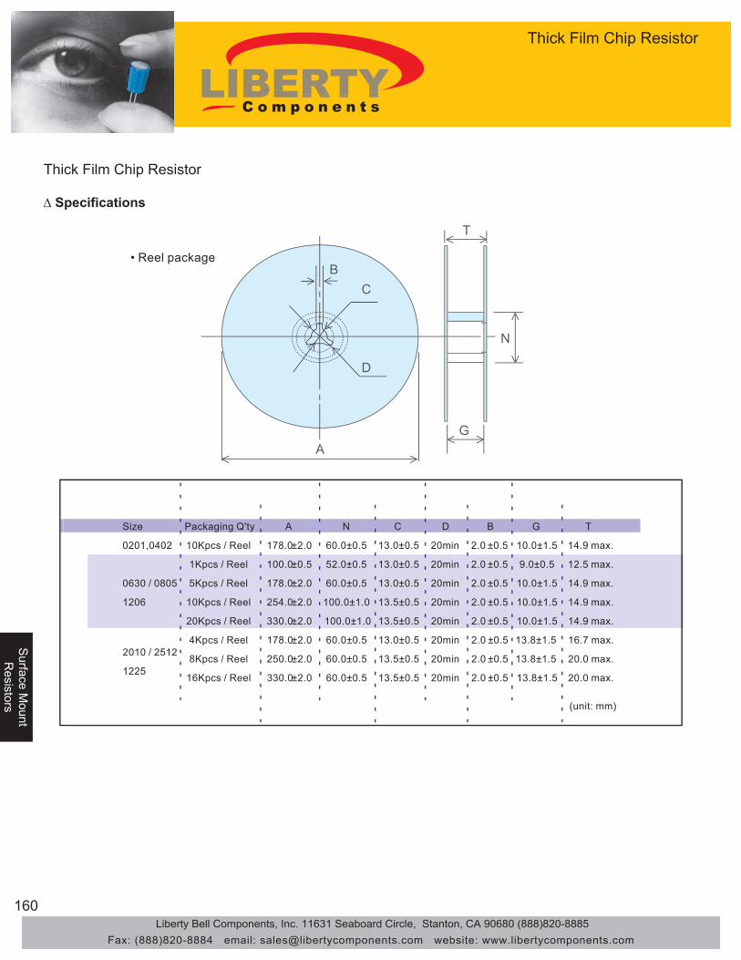
160
Surface M
ountS
urface Mount
Resistors
Resistors
Sur
face
Mou
ntR
esis
tors
Thick Film Chip Resistor
∆ Specifications
C
T
N
G
B
D
A
(unit: mm)
Size Packaging Q'ty A N C D B G T
0201,0402 10Kpcs / Reel 178.0±2.0 60.0±0.5 13.0±0.5 20min 2.0 ±0.5 10.0±1.5 14.9 max.
1Kpcs / Reel 100.0±0.5 52.0±0.5 13.0±0.5 20min 2.0 ±0.5 9.0±0.5 12.5 max.
0630 / 0805 5Kpcs / Reel 178.0±2.0 60.0±0.5 13.0±0.5 20min 2.0 ±0.5 10.0±1.5 14.9 max.
1206 10Kpcs / Reel 254.0±2.0 100.0±1.0 13.5±0.5 20min 2.0 ±0.5 10.0±1.5 14.9 max.
20Kpcs / Reel 330.0±2.0 100.0±1.0 13.5±0.5 20min 2.0 ±0.5 10.0±1.5 14.9 max.
4Kpcs / Reel 178.0±2.0 60.0±0.5 13.0±0.5 20min 2.0 ±0.5 13.8±1.5 16.7 max.2010 / 2512
8Kpcs / Reel 250.0±2.0 60.0±0.5 13.5±0.5 20min 2.0 ±0.5 13.8±1.5 20.0 max.1225
16Kpcs / Reel 330.0±2.0 60.0±0.5 13.5±0.5 20min 2.0 ±0.5 13.8±1.5 20.0 max.
• Reel package
Thick Film Chip Resistor
Liberty Bell Components, Inc. 11631 Seaboard Circle, Stanton, CA 90680 (888)820-8885Fax: (888)820-8884 email: [email protected] website: www.libertycomponents.com
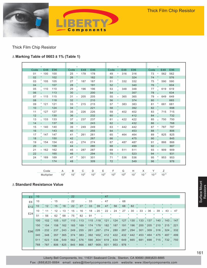
161
Surface M
ountR
esistors
Sur
face
Mou
ntS
urfa
ce M
ount
Res
isto
rsR
esis
tors
Thick Film Chip Resistor
∆ Marking Table of 0603 ± 1% (Table 1)
Code 01 02 03 04 05 06 07 08 09 10 11 12 13 14 15 16 17 18 19 20 21 22 24
E3
E6
E12 12
11
56
102
154
232
348
523
787
15
12
62
105
158
237
357
536
806
18
13
68
107
162
243
365
549
825
E48 100
105
110
115
121
127
133
140
147
154
162
169
E96 100 102 105 107 110 113 115 118 121 124 127 130 133 137 140 143 147 150 154 158 162 165 169 174
Code 25 26 27 28 29 30 31 32 33 34 35 36 37 38 39 40 41 42 43 44 45 46 47 48
E48 178
187
196
205
215
226
237
249
261
274
287
301
E96 178 182 187 191 196 200 205 210 215 221 226 232 237 243 249 255 261 267 274 280 287 294 301 309
Code 49 50 51 52 53 54 55 56 57 58 59 60 61 62 63 64 65 66 67 68 69 70 71 72
Code 73 74 75 76 77 78 79 80 81 82 83 84 85 86 87 88 89 90 91 92 93 94 95 96
E48 316
332
348
365
383
402
422
442
464
487
511
536
E96 316 324 332 340 348 357 365 374 383 392 402 412 422 432 442 453 464 475 487 499 511 523 536 549
E48 562
590
619
649
681
715
750
787
825
866
909
953
E96 562 576 590 604 619 634 649 665 681 698 715 732 750 768 787 806 825 845 866 887 909 931 953 976
Code Multiplier
A 100
B 101
C 102
D 103
E 104
F 105
G 106
H 107
X 10-1
Y 10-2
Z 10-3
22
15
75
110
165
249
374
562
845
27
16
82
113
169
255
383
576
866
33
18
91
115
174
261
392
590
887
39
20
118
178
267
402
604
909
47
22
121
182
274
412
619
931
56
24
124
187
280
422
634
953
68
27
127
191
287
432
649
976
82
30
130
196
294
442
665
33
133
200
301
453
681
36
137
205
309
464
698
39
140
210
316
475
715
43
143
215
324
487
732
47
147
221
332
499
750
E24
E96
10
10
51
100
150
226
340
511
768
10
10 15
22
22 33
47
47 68
∆ Standard Resistance Value
Thick Film Chip Resistor
Liberty Bell Components, Inc. 11631 Seaboard Circle, Stanton, CA 90680 (888)820-8885Fax: (888)820-8884 email: [email protected] website: www.libertycomponents.com

162
Surface M
ountS
urface Mount
Diodes
Diodes
Sur
face
Mou
ntD
iode
s
General Glass/Silicon RectifiersType PR - Surface Mount
Operating and Storage Temperature -55°C to +150°C∆ Specifications
MaximumPeak
Reverse Voltage
Maximum Forward Peak Surge Current
@ 8.3mS Superimposed
Maximum Reverse
Current @ PRV @25°C
TA
PRV IFM(Surge) IR IFM VFM
VPK AAV °C APK μAdc APK VPK
S1A 50 1.0 75 30 5.0 1.0 1.1S1B 100 1.0 75 30 5.0 1.0 1.1S1D 200 1.0 75 30 5.0 1.0 1.1S1G 400 1.0 75 30 5.0 1.0 1.1S1J 600 1.0 75 30 5.0 1.0 1.1S1K 800 1.0 75 30 5.0 1.0 1.1S1M 1000 1.0 75 30 5.0 1.0 1.1
2.0AMPERES/SMBS2A 50 2.0 70 70 5.0 2.0 1.0S2B 100 2.0 70 70 5.0 2.0 1.0S2D 200 2.0 70 70 5.0 2.0 1.0S2G 400 2.0 70 70 5.0 2.0 1.0S2J 600 2.0 70 70 5.0 2.0 1.0S2K 800 2.0 70 70 5.0 2.0 1.0S2M 1000 2.0 70 70 5.0 2.0 1.0
Maximum Forward Voltage @25°C TA
Maximum Rectified Current @ Half-Wave Resistive Load 60Hz
IO@TA
TYPE
1.0 AMPERES/SMA
Type PRGeneral Glass/Silicon Rectifiers
Liberty Bell Components, Inc. 11631 Seaboard Circle, Stanton, CA 90680 (888)820-8885Fax: (888)820-8884 email: [email protected] website: www.libertycomponents.com

163
Surface M
ountD
iodes
Sur
face
Mou
ntS
urfa
ce M
ount
Dio
des
Dio
des
General Glass/Silicon RectifiersType PR - Surface Mount
Operating and Storage Temperature -55°C to +150°C∆ Specifications
MaximumPeak
Reverse Voltage
Maximum Forward Peak Surge Current
@ 8.3mS Superimposed
Maximum Reverse
Current @ PRV @25°C
TA
PRV IFM(Surge) IR IFM VFM
VPK AAV °C APK μAdc APK VPK
S3AB 50 3.0 50 200 5.0 3.0 1.2S3BB 100 3.0 50 200 5.0 3.0 1.2S3DB 200 3.0 50 200 5.0 3.0 1.2S3GB 400 3.0 50 200 5.0 3.0 1.2S3JB 600 3.0 50 200 5.0 3.0 1.2S3KB 800 3.0 50 200 5.0 3.0 1.2S3MB 1000 3.0 50 200 5.0 3.0 1.2
S3A 50 3.0 50 200 5.0 3.0 1.2S3B 100 3.0 50 200 5.0 3.0 1.2S3D 200 3.0 50 200 5.0 3.0 1.2S3G 400 3.0 50 200 5.0 3.0 1.2S3J 600 3.0 50 200 5.0 3.0 1.2S3K 800 3.0 50 200 5.0 3.0 1.2S3M 1000 3.0 50 200 5.0 3.0 1.2
3.0AMPERES/SMD
Maximum Forward Voltage @25°C TA
Maximum Rectified Current @ Half-Wave Resistive Load 60Hz
IO@TA
TYPE
3.0 AMPERES/SMC
Type PRGeneral Glass/Silicon Rectifiers
Liberty Bell Components, Inc. 11631 Seaboard Circle, Stanton, CA 90680 (888)820-8885Fax: (888)820-8884 email: [email protected] website: www.libertycomponents.com

164
Surface M
ountS
urface Mount
Diodes
Diodes
Sur
face
Mou
ntD
iode
s
Glass/Silicon Passivated RectifiersType PR - Series S1
∆ Features● Glass/Silicon Passivated Chip● For surface mounted applications● Low forward voltage drop● Low reverse leakage current● High current capability● The plastic material carries UL flammability classification 94V-0
∆ Mechanical Data●Case: Molded plastic●Polarity: Indicated by cathode band●Weight: 0.002 ounces , 0.064 grams●Mounting position: Any
Ratings ar 25°C ambient temperature unless otherwise specified.
Single phase, half wave, 60Hz, resistive or inductive load.
For capacitance load, derate current by 20%
∆ Maximum Ratings and Electrical Characteristics
Reverse Voltage - 50 to 1000 VoltsForward Current - 1.0 Amperes
Dimensions in inches and (millimeters)
SMA
.055(1.40)
.062(1.60) .114(2.90).098(2.50)
.181(4.60).157(4.00)
.012(.305)
.006(.152)
.002(.051)
.008(.203).208(5.28).188(4.80)
.079(2.00).103(2.62)
.060(1.52).030(0.76)
Maximum Recurrent Peak Reverse Voltage VRRM 50 100 200 400 600 800 1000 V
Maximum RMS Voltage VRMS 35 70 140 280 420 560 700 V
Maximum DC Blocking Voltage VDC 50 100 200 400 600 800 1000 V
Maximum Average ForwardRectified Current @TL=100 °CPeak Forward Surge Current8.3ms Single Half Sine-WaveSuper Imposed On Rated Load (JEDEC Method)
Maximum Forward Voltage at 1.0A DC VF V
Maximum DC Reverse Current @TJ=25°Cat Rated DC Blocking Voltage @TJ=100°C
Typical Junction Capacitance (Note1) CJ pF
Typical Thermal Resistance (Note2) RθJC °C/W
Operating Temperature Range TJ °C
Storage Temperature Range TSTG °C
S1K S1MS1B S1D S1G S1J
IFSM A
I(AV) 1.0 A
30
S1A
NOTES:1.Measured at 1.0 MHz and applied reverse voltage of 4.0V DC.
2.Thermal resistance junction to lead.
uA
30
-55 to +150
SYMBOL UNITCHARACTERISTICS
IR1005.0
10
1.1
-55 to +150
Type PRGlass/Silicon Passivated Rectifiers
Series S1
Liberty Bell Components, Inc. 11631 Seaboard Circle, Stanton, CA 90680 (888)820-8885Fax: (888)820-8884 email: [email protected] website: www.libertycomponents.com

165
Surface M
ountD
iodes
Sur
face
Mou
ntS
urfa
ce M
ount
Dio
des
Dio
des
Glass/Silicon Passivated RectifiersType PR - Series S1
∆ Rating and Characteristics Curves
25 50 75 100 125 150 175
1.0
0.8
0.6
0.4
0.2
0
SINGLE PHASE HALF WAVE 60HZ RESISTIVE OR INDUCTIVE LOAD
FIG. 1 - FORWARD CURRENT DERATING CURVE
AV
ER
AG
EFO
RW
AR
DC
UR
RE
NT
AM
PE
RE
S
LEAD TEMPERATURE °C
TJ=25°CPULSE WIDTH 300US
10
1.0
0.1
0.01
0 0.2 0.4 0.6 0.8 1.0 1.2 1.4 1.6 1.8
FIG.3-TYPICAL FORWARD CHARACTERISTICS
INST
ANTA
NE
OU
SFO
RW
ARD
CU
RE
NT,
(A)
INSTANTANEOUS FORWARD VOLTAGE,VOLTS
FIG.4-TYPICAL REVERSE CHARACTERISTICS
PERCENT RATED PEAK REVERSE VOLTAGE,(%)
INS
TAN
TAN
EO
US
RE
VE
RS
EC
UR
RE
NT,
(uA
)
1000
100
10
1.0
0.1
0.010 20 40 60 80 100 120 140
TJ=125°C
TJ=25°C
FIG.2 - MAXIMUM NON-REPETITIVESURGE CURRENT
PE
AK
FOR
WA
RD
SU
RG
EC
UR
RE
NT,
AM
PE
RE
S
NUMBER OF CYCLES AT
1 2 5 10 20 50 100
30
10
0
20
PULSE WIDTH 8.3mSSINGLE HALF-SINE-WAVE
(JEDEC METHOD)
Type PRGlass/Silicon Passivated Rectifiers
Series S1
Liberty Bell Components, Inc. 11631 Seaboard Circle, Stanton, CA 90680 (888)820-8885Fax: (888)820-8884 email: [email protected] website: www.libertycomponents.com

166
Surface M
ountS
urface Mount
Diodes
Diodes
Sur
face
Mou
ntD
iode
s
Glass/Silicon Passivated RectifiersType PR - S2A Thru S2M
∆ Features● Glass/Silicon Passivated Chip● For surface mounted applications● Low forward voltage drop● Low reverse leakage current● High current capability● The plastic material carries UL flammability classification 94V-0
∆ Mechanical Data●Case: Molded plastic●Polarity: Indicated by cathode band●Weight: 0.002 ounces , 0.064 grams●Mounting position: Any
Ratings ar 25°C ambient temperature unless otherwise specified.
Single phase, half wave, 60Hz, resistive or inductive load.
For capacitance load, derate current by 20%
∆ Maximum Ratings and Electrical Characteristics
Reverse Voltage - 50 to 1000 VoltsForward Current - 2.0 Amperes
Dimensions in inches and (millimeters)
SMB
.030(0.76)
.060(1.52)
.096(2.44).084(2.13)
.200(5.08)
.220(5.59).008(.203).002(.051)
.006(.152).012(.305)
.160(4.06).185(4.70)
.130(3.30).155(3.94).083(2.11)
.075(1.91)
CHARACTERISTICS SYMBOL S2A S2B S2D S2G S2J S2K S2M UNIT
Maximum Recurrent Peak Reverse Voltage VRRM 50 100 200 400 600 800 1000 V
Maximum RMS Voltage VRMS 35 70 140 280 420 560 700 V
Maximum DC Blocking Voltage VDC 50 100 200 400 600 800 1000 V
Maximum Average ForwardRectified Current @TL=100°CPeak Forward Surge Current8.3ms Single Half Sine-WaveSuper Imposed On Rated Load (JEDEC Method)
Maximum Forward Voltage at 2.0A DC VF V
Maximum DC Reverse Current @TJ=25°Cat Rated DC Blocking Voltage @TJ=100°C
Typical Junction Capacitance (Note1) CJ pF
Typical Thermal Resistance (Note2) RθJL °C /W
Operating Temperature Range TJ °C
Storage Temperature Range TSTG °C
2.Thermal resistance junction to lead.
IR1255.0
20
20
-55 to +150
-55 to +150
NOTES:1.Measured at 1.0 MHz and applied reverse voltage of 4.0V DC.
IFSM A
I(AV) 2.0 A
70
uA
1.0
Type PRGlass/Silicon Passivated Rectifiers
S2A Thru S2M
Liberty Bell Components, Inc. 11631 Seaboard Circle, Stanton, CA 90680 (888)820-8885Fax: (888)820-8884 email: [email protected] website: www.libertycomponents.com

167
Surface M
ountD
iodes
Sur
face
Mou
ntS
urfa
ce M
ount
Dio
des
Dio
des
Glass/Silicon Passivated RectifiersType PR - S2A Thru S2M
∆ Rating and Characteristics Curves
FIG.4-TYPICAL REVERSE CHARACTERISTICS
PERCENT RATED PEAK REVERSE VOLTAGE,(%)
INS
TAN
TAN
EO
US
RE
VE
RS
EC
UR
RE
NT,
(uA
)
1000
10
10
1.0
0.1
0.010 20 40 60 80 100 120 140
TJ=125°C
TJ=25°C
FIG.3-TYPICAL FORWARD CHARACTERISTICS
INS
TAN
TAN
EO
US
FOR
WA
RD
CU
RE
NT,
(A)
INSTANTANEOUS FORWARD VOLTAGE,VOLTS
TJ=25°CPULSE WIDTH 300US
10
1.0
0.1
0.01
0 0.2 0.4 0.6 0.8 1.0 1.2 1.4 1.6 1.8
FIG. 1 – FORWARD CURRENT DERATING
LEAD TEMPERATURE °C
AV
ER
AG
EFO
RW
AR
DC
UR
RE
NT
(AM
PE
RE
S)
1.0
0.5
025
3.0
1.5
2.0
2.5
50 12510075 150 175
SINGLE PHASE HALF WAVE 60HzRESISTIVE OR INDUCTIVE LOAD
NUMBER OF CYCLES AT 60Hz
FIG. 2 – MAXIMUM NON-REPETITIVE SURGE CURRENT
PE
AK
FOR
WA
RD
SU
RG
EC
UR
RE
NT
(AM
PE
RE
S)
1
5040
30
20
100
60
2 5 10 20 10050
70
PULSE WIDTH 8.3msSINGLE HALF-SINE-WAVE
(JEDEC METHOD)
Type PRGlass/Silicon Passivated Rectifiers
S2A Thru S2M
Liberty Bell Components, Inc. 11631 Seaboard Circle, Stanton, CA 90680 (888)820-8885Fax: (888)820-8884 email: [email protected] website: www.libertycomponents.com

168
Surface M
ountS
urface Mount
Diodes
Diodes
Sur
face
Mou
ntD
iode
s
Glass/Silicon Passivated RectifiersType PR - SM3AB Thru SM3MB
∆ Features● Glass/Silicon Passivated Chip● For surface mounted applications● Low forward voltage drop● Low reverse leakage current● High current capability● The plastic material carries UL flammability classification 94V-0
∆ Mechanical Data●Case: Molded plastic●Polarity: Indicated by cathode band●Weight: 0.002 ounces , 0.064 grams●Mounting position: Any
Ratings ar 25°C ambient temperature unless otherwise specified.
Single phase, half wave, 60Hz, resistive or inductive load.
For capacitance load, derate current by 20%
∆ Maximum Ratings and Electrical Characteristics
Reverse Voltage - 50 to 1000 VoltsForward Current - 3.0 Amperes
Dimensions in inches and (millimeters)
SMB
.030(0.76).060(1.52)
.096(2.44).084(2.13)
.200(5.08).220(5.59)
.008(.203).002(.051)
.006(.152).012(.305)
.160(4.06)
.185(4.70)
.130(3.30).155(3.94).083(2.11)
.075(1.91)
CHARACTERISTICS SYMBOL S3AB S3BB S3DB S3GB S3JB S3KB S3MB UNIT
Maximum Recurrent Peak Reverse Voltage VRRM 50 100 200 400 600 800 1000 V
Maximum RMS Voltage VRMS 35 70 140 280 420 560 700 V
Maximum DC Blocking Voltage VDC 50 100 200 400 600 800 1000 V
Maximum Average ForwardRectified Current @TL=75°CPeak Forward Surge Current8.3ms Single Half Sine-WaveSuper Imposed On Rated Load (JEDEC Method)
Maximum Forward Voltage at 3.0A DC VF V
Maximum DC Reverse Current @TJ=25°Cat Rated DC Blocking Voltage @TJ=100°C
Typical Junction Capacitance (Note1) CJ pF
Typical Thermal Resistance (Note2) RθJL °C /W
Typical Thermal Resistance (Note3) RθJA °C /W
Operating Temperature Range TJ °C
Storage Temperature Range TSTG °C
IR2505.0
40
10
-55 to +150
3.Thermal resistance junction to ambient.
-55 to +150
NOTES:1.Measured at 1.0 MHz and applied reverse voltage of 4.0V DC.
2.Thermal resistance junction to lead.
uA
1.2
50
IFSM A
I(AV) 3.0 A
200
Type PRGlass/Silicon Passivated Rectifiers
SM3AB Thru SM3MB
Liberty Bell Components, Inc. 11631 Seaboard Circle, Stanton, CA 90680 (888)820-8885Fax: (888)820-8884 email: [email protected] website: www.libertycomponents.com

169
Surface M
ountD
iodes
Sur
face
Mou
ntS
urfa
ce M
ount
Dio
des
Dio
des
Glass/Silicon Passivated RectifiersType PR - SM3AB Thru SM3MB
∆ Rating and Characteristics Curves
FIG. 1 - FORWARD CURRENT DERATING CURVE
AV
ER
AG
EFO
RW
AR
DC
UR
RE
NT
AM
PE
RE
S
LEAD TEMPERATURE °C
25 50 75 100 125 150 175
5.0
4.0
3.0
2.0
1.0
0
SINGLE PHASE HALF WAVE 60Hz RESISTIVE OR INDUCTIVE LOAD
FIG.2 - MAXIMUM NON-REPETITIVESURGE CURRENT
PE
AK
FOR
WA
RD
SU
RG
EC
UR
RE
NT,
AM
PE
RE
S
NUMBER OF CYCLES AT 60Hz
PULSE WIDTH 8.3msSINGLE HALF-SINE-WAVE(JEDEC METHOD)
1 2 5 10 20 50 100
120
40
0
80
160
200
FIG.4-TYPICAL REVERSE CHARACTERISTICS
PERCENT RATED PEAK REVERSE VOLTAGE,(%)
INS
TAN
TAN
EO
US
RE
VE
RS
EC
UR
RE
NT,
(uA
)
1000
100
10
1.0
0.1
0.010 20 40 60 80 100 120 140
TJ=125°C
TJ=25°C
FIG.3-TYPICAL FORWARD CHARACTERISTICS
INST
ANTA
NE
OU
SFO
RW
ARD
CU
RE
NT,
(A)
INSTANTANEOUS FORWARD VOLTAGE,VOLTS
TJ=25°CPULSE WIDTH 300US
10
1.0
0.1
0.01
0 0.2 0.4 0.6 0.8 1.0 1.2 1.4 1.6 1.8
Type PRGlass/Silicon Passivated Rectifiers
SM3AB Thru SM3MB
Liberty Bell Components, Inc. 11631 Seaboard Circle, Stanton, CA 90680 (888)820-8885Fax: (888)820-8884 email: [email protected] website: www.libertycomponents.com
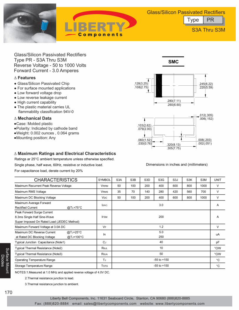
170
Surface M
ountS
urface Mount
Diodes
Diodes
Sur
face
Mou
ntD
iode
s
Glass/Silicon Passivated RectifiersType PR - S3A Thru S3M
∆ Features● Glass/Silicon Passivated Chip● For surface mounted applications● Low forward voltage drop● Low reverse leakage current● High current capability● The plastic material carries UL flammability classification 94V-0
∆ Mechanical Data●Case: Molded plastic●Polarity: Indicated by cathode band●Weight: 0.002 ounces , 0.064 grams●Mounting position: Any
Ratings ar 25°C ambient temperature unless otherwise specified.
Single phase, half wave, 60Hz, resistive or inductive load.
For capacitance load, derate current by 20%
∆ Maximum Ratings and Electrical Characteristics
Reverse Voltage - 50 to 1000 VoltsForward Current - 3.0 Amperes
Dimensions in inches and (millimeters)
.108(2.75)
.128(3.25) .245(6.22).220(5.59)
.280(7.11).260(6.60)
.012(.305).006(.152)
.002(.051)
.008(.203).320(8.13).305(7.75)
.079(2.00).103(2.62)
.060(1.52).030(0.76)
SMC
CHARACTERISTICS SYMBOL S3A S3B S3D S3G S3J S3K S3M UNIT
Maximum Recurrent Peak Reverse Voltage VRRM 50 100 200 400 600 800 1000 V
Maximum RMS Voltage VRMS 35 70 140 280 420 560 700 V
Maximum DC Blocking Voltage VDC 50 100 200 400 600 800 1000 V
Maximum Average ForwardRectified Current @TL=75°CPeak Forward Surge Current8.3ms Single Half Sine-WaveSuper Imposed On Rated Load (JEDEC Method)
Maximum Forward Voltage at 3.0A DC VF V
Maximum DC Reverse Current @TJ=25°Cat Rated DC Blocking Voltage @TJ=100°C
Typical Junction Capacitance (Note1) CJ pF
Typical Thermal Resistance (Note2) RθJL °C/W
Typical Thermal Resistance (Note3) RθJA °C/W
Operating Temperature Range TJ °C
Storage Temperature Range TSTG °C
IFSM A
I(AV) 3.0 A
200
2.Thermal resistance junction to lead.
uA
1.2
50
IR2505.0
40
10
-55 to +150
3.Thermal resistance junction to ambient.
-55 to +150
NOTES:1.Measured at 1.0 MHz and applied reverse voltage of 4.0V DC.
Type PRGlass/Silicon Passivated Rectifiers
S3A Thru S3M
Liberty Bell Components, Inc. 11631 Seaboard Circle, Stanton, CA 90680 (888)820-8885Fax: (888)820-8884 email: [email protected] website: www.libertycomponents.com

171
Surface M
ountD
iodes
Sur
face
Mou
ntS
urfa
ce M
ount
Dio
des
Dio
des
Glass/Silicon Passivated RectifiersType PR - S3A Thru S3M
∆ Rating and Characteristics Curves
FIG. 1 - FORWARD CURRENT DERATING CURVE
AV
ER
AG
EFO
RW
AR
DC
UR
RE
NT
AM
PE
RE
S
LEAD TEMPERATURE °C
25 50 75 100 125 150 175
5.0
4.0
3.0
2.0
1.0
0
SINGLE PHASE HALF WAVE 60Hz RESISTIVE OR INDUCTIVE LOAD
FIG.4-TYPICAL REVERSE CHARACTERISTICS
PERCENT RATED PEAK REVERSE VOLTAGE,(%)
INS
TAN
TAN
EO
US
RE
VE
RS
EC
UR
RE
NT,
(uA
)
1000
100
10
1.0
0.1
0.010 20 40 60 80 100 120 140
TJ=125°C
TJ=25°C
FIG.3-TYPICAL FORWARD CHARACTERISTICS
INS
TAN
TAN
EO
US
FOR
WA
RD
CU
RE
NT,
(A)
INSTANTANEOUS FORWARD VOLTAGE,VOLTS
TJ=25°CPULSE WIDTH 300US
10
1.0
0.1
0.01
0 0.2 0.4 0.6 0.8 1.0 1.2 1.4 1.6 1.8
FIG.2 - MAXIMUM NON-REPETITIVESURGE CURRENT
PE
AK
FOR
WA
RD
SU
RG
EC
UR
RE
NT,
AM
PE
RE
S
NUMBER OF CYCLES AT 60Hz
PULSE WIDTH 8.3msSINGLE HALF-SINE-WAVE(JEDEC METHOD)
1 2 5 10 20 50 100
120
40
0
80
160
200
Type PRGlass/Silicon Passivated Rectifiers
S3A Thru S3M
Liberty Bell Components, Inc. 11631 Seaboard Circle, Stanton, CA 90680 (888)820-8885Fax: (888)820-8884 email: [email protected] website: www.libertycomponents.com

172
Surface M
ountS
urface Mount
Diodes
Diodes
Sur
face
Mou
ntD
iode
s