Embed Size (px)
Citation preview

International:
Connect One Ltd. 20 Atir Yeda Street Kfar Saba 44643, Israel Phone: +972-9-766-0456 Fax: +972-9-766-0461 Email: [email protected] http://www.connectone.com
Pub. No. 23-3830-01
Instant Internet Evaluation Board
II-EVB-365SMT
User Manual Version 1.00
Copyright © 2011 Connect One Ltd.

International:
Connect One Ltd. 20 Atir Yeda Street Kfar Saba 44643, Israel Phone: +972-9-766-0456 Fax: +972-9-766-0461 Email: [email protected] http://www.connectone.com
Pub. No. 23-3830-01
Information provided by Connect One Ltd. is believed to be accurate and reliable.
However, Connect One assumes no responsibility for its use, nor any infringement of
patents or other rights of third parties, which may result from its use. No license is
granted by implication or otherwise under any patent rights of Connect One other than
for circuitry embodied in Connect One’s products. Connect One reserves the right to
change circuitry at any time without notice. This document is subject to change
without notice.
The software described in this document is furnished under a license agreement and
may be used or copied only in accordance with the terms of such a license agreement.
It is forbidden by law to copy the software on any medium except as specifically
allowed in the license agreement. No part of this document may be reproduced or
transmitted in any form or by any means, electronic or mechanical, including but not
limited to photocopying, recording, transmitting via fax and/or modem devices,
scanning, and/or information storage and retrieval systems for any purpose without
the express written consent of Connect One.
iChip, Nano WiReach, Nano WiReach SMT, Nano LANReach, Nano Socket iWiFi,
Nano Socket LAN, IP Communication Controller, SerialNET, AT+i, and
Connect One are trademarks of Connect One Ltd.
Copyright 2011 Connect One Ltd. All rights reserved.
Connect One
II-EVB-365 SMT User’s Manual 3
TABLE OF CONTENTS
1. Introduction ............................................................................................................ 4
2. Unpacking .............................................................................................................. 4
3. Connections ............................................................................................................ 4
4. Installing the iChipConfig Utility & Evaluation Software .................................... 5
5. Testing the WiFi module Wireless Connection ..................................................... 5
6. Testing the Nano WiReach SMT Ethernet Connection ......................................... 6
7. Additional Connections ......................................................................................... 7
SPI Slave .................................................................................................................... 7
8. II-EVB-365 SMT Bill of Materials ........................................................................ 9
Appendix 1: Nano WiReach SMT Mechanical Views ................................................ 10
Appendix 2: Installing USB Drivers on a PC .............................................................. 11
Installing the USB driver: ........................................................................................ 11
Viewing the properties of the new driver: ............................................................... 14
FAQs ........................................................................................................................ 16
Appendix 3: WiFi Configuration Notes ....................................................................... 17
Introduction .............................................................................................................. 17
iChip Wireless LAN Environment Configuration Parameters ................................ 18
Wireless LAN Configuration Web Site Page .......................................................... 19
Wireless LAN Status Report .................................................................................... 19
iChip Wireless LAN Test Mode .............................................................................. 20
Placement and Range Guidelines ............................................................................. 21
Wireless LAN Data Privacy/Security Considerations ............................................. 21
Appendix 4: SPI Host Interface ................................................................................... 22
Introduction .............................................................................................................. 22
SPI Protocol ............................................................................................................. 22
Data from module to Host (Slave to Master) ........................................................... 22
Flow Control - Data from Host to iChip Flow Control ........................................... 23
iSPIP — SPI GPIO Pin ............................................................................................ 23
iHIF — Host Interface ............................................................................................. 23
Connect One
II-EVB-365 SMT User’s Manual 4
1. Introduction
This manual is intended to familiarize customers with Connect One’s Instant Internet
Evaluation Board II-EVB-365SMT. The II-EVB-365SMT is an evaluation platform
for the Nano WiReach™ SMT Module, which is a secure serial-to-WiFi / serial-to-
LAN module that provides a wide range of commands to initiate Internet connectivity
and can also act as a bridge to connect serial devices to wired Ethernet or 802.11b/g
wireless LANs. Furthermore, the module can also be configured as a full-blown router
between LAN and WiFi subnets. With an external USB modem communications and
routing are extended to the cellular network, providing for a unique mobile router
capability. The module has an economic SMT form factor and is based on
Connect One’s iChip CO2144 IP Communication Controller™ and the AT+i™
command set, a powerful set of Internet protocol commands developed by
Connect One to manage Internet connectivity through an Ethernet, Wireless LAN or
cellular connection.
The module enables sending and receiving textual and binary data, MIME-encoded
email messages; downloading HTML pages or files from a Web server, or items from
within a page; Web serving, as well as managing TCP or UDP socket
communications (with or without SSL3) over the Internet. It also include an FTP
client and a TELNET client.
Nano WiReach SMT can easily connect existing LAN based solutions to a WiFi
network when used in bridging mode.
Nano WiReach SMT supports numerous WiFi security protocols such as 64/128-bit
WEP encryption, AES-CCM and TKIP encryption, WPA (including AES) and WPA2
in both PSK and Enterprise modes. The module also supports the SSL3/TLS1 security
protocols.
When used as a router, the Nano WiReach SMT provides IP allocation via a DHCP
server and NAT translation when routing packets between a local subnet and a WAN.
Three-way routing between wired-LAN, WiFi and a cellular network is fully
supported. In routing mode, port-forward rules may be configured between the WAN
connection and any specific local subnet node.
2. Unpacking
Take the II-EVB-365 SMT out of its box. Included in the box are:
The II-EVB-365 SMT motherboard incorporating the iW- SM2144SMT-OB
(Nano WiReach SMT module with On-board antenna).
A serial cable with two DB-9 connectors
A USB cable
+9VDC Power supply adaptor (110/220 VAC)
3. Connections
1. Communications Cable:
Serial RS232: Connect one end of the RS232 cable to the D-shell, 9-
pin female, Host RS232 port on the II-EVB-365 SMT (J5) and connect
Connect One
II-EVB-365 SMT User’s Manual 5
the other DB-9 connector to the COM1 or COM2 serial port on your
PC, or to the serial port of your embedded device.
USB: Connect one the device end of the USB cable to the EVB-365
SMT USB connector (J10) and connect the other end to a Host USB
port on your PC or embedded device.
2. Connect the II-EVB-365 SMT to the power supply.
4. Installing the iChipConfig Utility & Evaluation Software
II-EVB-365 SMT enables you to evaluate the Nano WiReach SMT module without
changing anything in your current development environment. Using a simple terminal
program on a PC, you can issue AT+i commands to the module and get responses.
AT+i commands are used to configure parameter values into iChip’s flash memory
and activate Internet tasks such as Email send/receive, socket manipulation, FTP
sessions, Web, and more.
A full description of the AT+i protocol can be found in the AT+i Programmer’s
Manual on the Connect One website at:
http://www.connectone.com/support.asp?did=42
To assist in configuring and evaluating the iChip, Connect One supplies the
iChipConfig Utility. This is a Windows-based GUI program that contains intuitive
dialog boxes to fully configure iChip. It doesn’t require any knowledge of AT+i
commands. In addition, it contains a local firmware upgrade function.
The iChipConfig Utility also allows you to perform specific Internet communication
tasks such as sending and receiving Emails, activating iChip’s websites, entering
SerialNET mode, and more.
For more information on the iChipConfig Utility and its usage, see the iChip Config
Utility User’s Manual.
. The latest iChipConfig Utility version and user manual can be found on the
Connect One website in the Support section at:
http://www.connectone.com/support.asp?did=30
Most frequently iChipConfig connects to the II-EVB-365 SMT though the PC’s
standard RS232 Serial port. A USB Device port is also available, which allows using
a USB connection as an alternative. To enable use of the PC USB port, a virtual COM
USB driver needs to be loaded on the PC. The iChipConfig can then be configured to
use the virtual port. Instructions for configuring the USB drivers on the PC are given
below in Appendix 2.
5. Testing the WiFi module Wireless Connection
To test the wireless LAN connection, you need to configure the Nano WiReach SMT
to connect to an Access Point:
1. Make sure an Access Point is connected and configured properly.
2. Start the iChipConfig Utility on your PC.

Connect One
II-EVB-365 SMT User’s Manual 6
3. In the main window of the utility, click the Dumb Terminal icon.
4. In the Dumb Terminal window, enter the AT+i command to verify that the
iChip is communicating with your PC. You should receive an I/OK in
response. If this has failed, click the ―Setup Port‖ button and select the correct
COM port. When using a USB connection, select the USB virtual COM being
used.
5. Enter the AT+iRP11 command to obtain a report of all the Access Points
available in your area.
6. Enter AT+iWLSI=<ssid>. ssid is the ID of the Access Point you connect to.
Note that ssid is a case-sensitive string.
7. If you want to enable WEP encryption, configure the following parameters:
AT+iWLWM=<n> where n=0 means no security, n=1 means 64-bit
key, and n=2 means 128-bit key
AT+iWLKI=<n> where n is the WEP key index (n=1..4)
AT+iWLK<n>=<keyString> where n is an index between 1 and 4, and
keyString is the WEP key string in the nth
position.
8. If you want to enable WPA encryption, configure the following parameter:
AT+iWLPP=<passphrase> where passphrase is the pass-phrase to
be used in generating the WPA1-PSK encryption key. It is normal for the
iChip to take a few moments before returning I/OK in this case.
9. Enter AT+iDOWN in order to reset the module and connect to the WiFi
network.
At this stage a connection to the Access Point should be established. Verify that
the module has received an IP address from the DHCP server by issuing the
AT+iIPA? command. The module should reply with I/<IP address>.
To test the connection, use the iChipConfig utility to perform any activity that
requires network connection such as retrieving a web page, sending an email, or
opening a socket. You may also try to PING the iChip from another station on the
network.
6. Testing the Nano WiReach SMT Ethernet Connection
The II-EVB-365 SMT contains a standard 10/100BaseT RJ45 connector that allows a
direct connection to a wired LAN. To test the Ethernet LAN connection, you need to
configure the Nano WiReach SMT for your LAN:
1. Connect the module to the LAN network.
2. Start the iChipConfig Utility on your PC.
3. In the main window of the utility, click the Dumb Terminal icon.
4. In the Dumb Terminal window, enter the AT+i command to verify that the
iChip is communicating with your PC. You should receive an I/OK in
response. If this has failed, click the ―Setup Port‖ button and select the correct
COM port. When using a USB connection, select the USB virtual COM being
used.
5. Configure the module IP address in the +iDIP parameter. Set
AT+iDIP=0.0.0.0 if you want the module to receive IP settings for the
network’s DHCP server.
6. Set +iDIP to an IP address to skip the DHCP process and use a fixed IP. In this
case you should also define the +iSNET (subnet) parameter. For example,
AT+iSNET=255.255.255.0

Connect One
II-EVB-365 SMT User’s Manual 7
7. Change the LAN type parameter to 2 (LAN) using the following command:
AT+iLTYP=2
8. Enter AT+iDOWN in order to reset the module and connect to the LAN
network.
To test the connection, use the iChipConfig utility to perform any activity that
requires network connection such as retrieving a web page, sending an email,
or opening a socket. You may also try to PING the iChip from another station
on the network.
9. Restore the LTYP parameter to zero to return to the default Wireless-LAN
operation.
7. Additional Connections
The modules support two additional connections:
SPI Slave The modules support an alternative Host interface to the RS232 Serial port and the
USB connection. A host equipped with an SPI Master connection may connect to the
module’s SPI Slave port and interact with the module with AT+i commands.
An SPI cable (not supplied) connects to the II-EVB-365 SMT J2 SIP connector:
A full description of interfacing the modules with SPI is included below in Appendix 4.
nSPI_INT nSPI_MISO
nSPI_MOSI
nSPI_CLK nSPI_CS
GND
J2
1

Connect One
II-EVB-365 SMT User’s Manual 8
Connectors and Switch Positions
RS232 Serial
Connection
+9VDC
USB Power
Jack
Power
Switch
Module
Reset
Mode
Select
USB
Connection
RJ45 LAN
Nano WiReach SMT
Module POT for A/D
Input
SPI
Connection
Cellular
Modem
GPIO
Switches

Connect One
II-EVB-365 SMT User’s Manual 9
8. II-EVB-365 SMT Bill of Materials
Item Quant. Reference Part Manufacturer
1 3 C1,C39,C40 47PF Any 2 9 C2,C4,C5,C6,C8,C10,C13,C16,C36 470NF Any
3 5 C3,C9,C30,C31,C38 10UF/6.3V Any
4 18 C7,C11,C12,C14,C15,C17,C18,C19,C20,C23, C24,C25,C26,C27,C28,C29,C35,C37 100NF Any
5 2 C21,C22 100UF/6.3V Any 6 1 C34 220UF/10V Any 7 2 C41,C42 15PF Any 8 10 D1,D3,D4,D5,D6,D7,D8,D9,D10,D14 GREEN LED Any 9 1 D2 LLN4148 Any
10 1 D13 RED LED Any 11 1 JP3 JUMPER Any 12 1 J2 CON6 Any 13 1 J5 DB9 FEM Any 14 1 J7 203199 ERNI 15 1 J8 USB MINI B Any 16 1 J9 USB-A Any 17 1 J10 USB-B Any 18 1 L1 BK2125HM601 Taiyo Yuden 19 1 P1 POT 10K Any
20 13 R1,R2,R4,R5,R6,R7,R13,R14,R19,R20,R23, R25,R44 100k Any
21 15 R8,R9,R11,R12,R15,R16,R17,R18,R21,R22, R24,R39,R40,R42,R46 470 Any
22 4 R10,R29,R30,R31 10K Any 23 6 R26,R27,R33,R34,R35,R36 49.9 1% Any 24 2 R28,R32 3K Any 25 1 R37 0 Any 26 1 R38 6.8K1% Any 27 1 R43 100k Any 28 1 R45 1K Any 29 4 R47,R49,R51,R52 27 Any 30 2 R48,R50 15K Any 31 2 R53,R54 75K Any 32 2 R55,R56 49.9K Any 33 5 SW1,SW2,SW3,SW4,SW5 TACK_SW Any 34 1 SW6 SWITCH Any 35 1 U1 SP3243ECA Sipex 36 1 U2 iW-SM2144SMT Connectone 37 2 U3,U6 74VHC123AMTCX Fairchild 38 3 U4,U5,U7 NC7WZ04P6X Fairchild 39 1 U8 F4100-50MHZ Fox Online 40 1 U9 DM9161A davicom
Connect One
II-EVB-365 SMT User’s Manual 10
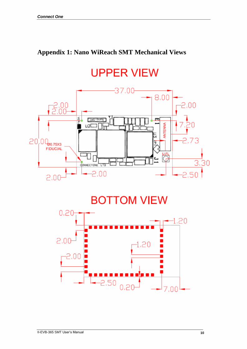
Appendix 1: Nano WiReach SMT Mechanical Views

Connect One
II-EVB-365 SMT User’s Manual 11
Appendix 2: Installing USB Drivers on a PC
Installing the USB driver:
The USB driver is supplied in three separate files: sabalo.inf, iChip.inf and usbser.sys.
These files may be obtained on the Connect One Web site under:
Support >> Drivers & Utilities at: http://www.connectone.com/support.asp?did=30.
1. Copy “sabalo.inf” and “iChip.inf” to the directory C:\WINDOWS\inf. To view the \inf directory, you must allow viewing of hidden folders in Folder Options. 2. Copy usbser4.sys to C:\WINDOWS\system32\drivers. 3. Connect one end of a USB cable to your PC. Connect the other end to the USB
“device” connector of the II-EVB-365 SMT board on which the module is mounted.
4. Turn on the power to the EVB board. 5. The “Found New Hardware Wizard” of Windows XP pops up and prompts you to install a new device driver. When prompted with the message “Can Windows connect to Windows Update to search for software?” Select No, not this time. See Figure 1.
Figure 1
Connect One
II-EVB-365 SMT User’s Manual 12
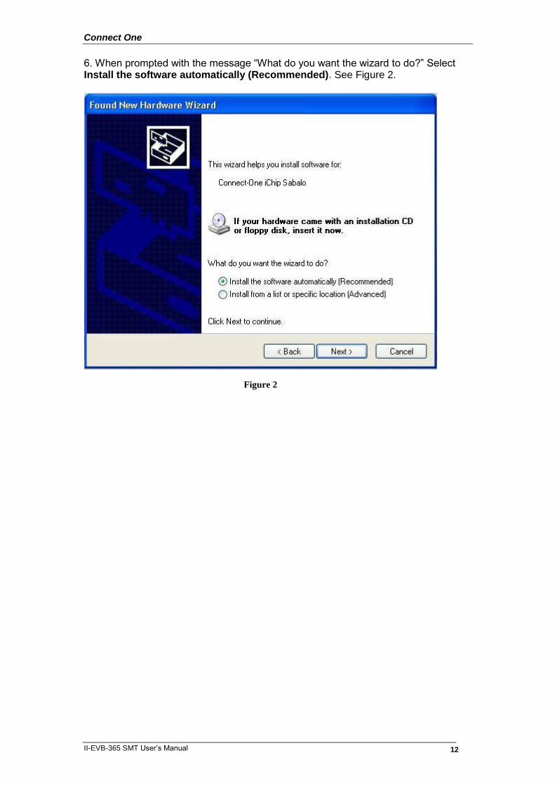
6. When prompted with the message “What do you want the wizard to do?” Select Install the software automatically (Recommended). See Figure 2.
Figure 2
Connect One
II-EVB-365 SMT User’s Manual 13
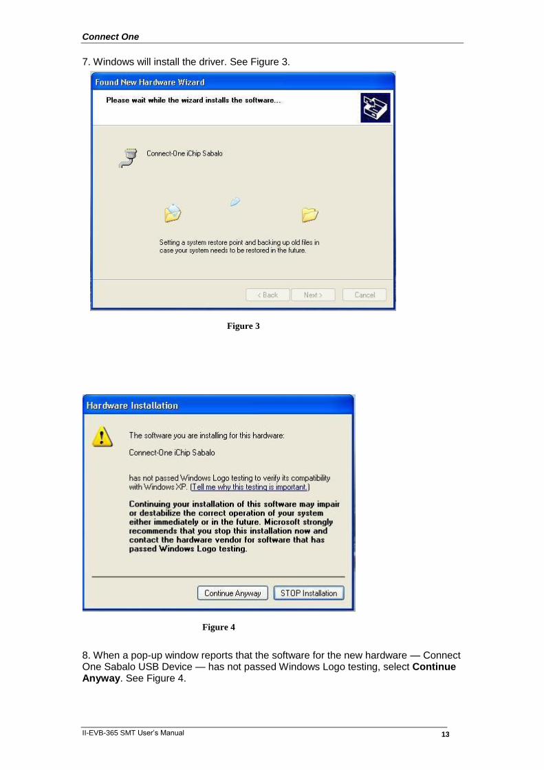
7. Windows will install the driver. See Figure 3.
8. When a pop-up window reports that the software for the new hardware — Connect One Sabalo USB Device — has not passed Windows Logo testing, select Continue Anyway. See Figure 4.
Figure 3
Figure 4
Connect One
II-EVB-365 SMT User’s Manual 14
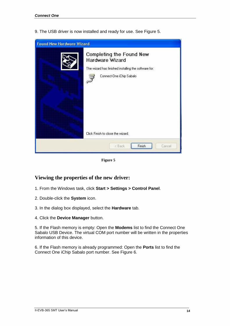
9. The USB driver is now installed and ready for use. See Figure 5.
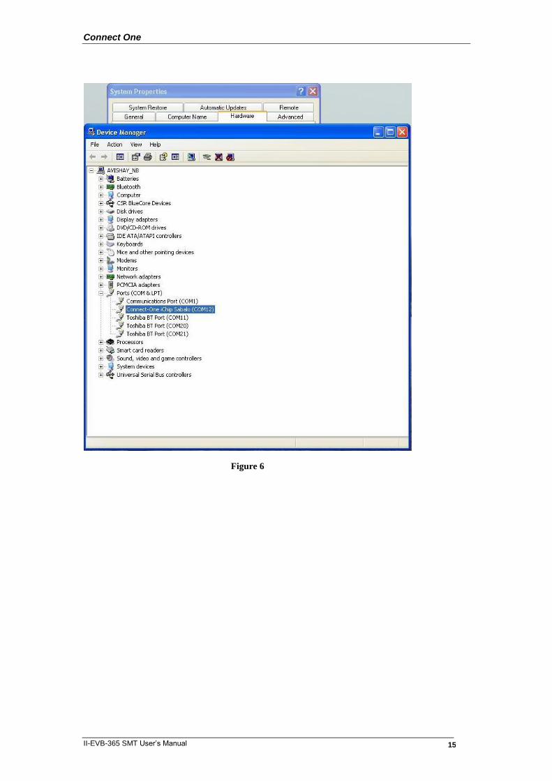
Viewing the properties of the new driver: 1. From the Windows task, click Start > Settings > Control Panel. 2. Double-click the System icon. 3. In the dialog box displayed, select the Hardware tab. 4. Click the Device Manager button. 5. If the Flash memory is empty: Open the Modems list to find the Connect One Sabalo USB Device. The virtual COM port number will be written in the properties information of this device. 6. If the Flash memory is already programmed: Open the Ports list to find the Connect One iChip Sabalo port number. See Figure 6.
Figure 5
Connect One
II-EVB-365 SMT User’s Manual 15
Figure 6

Connect One
II-EVB-365 SMT User’s Manual 16
FAQs
Q: What should I do if Windows does not automatically locate the driver for the new
hardware?
A: Please use the ―Back‖ button to browse to the previous step and manually browse
to the directory of the iChip Configuration Utility, usually located in ―C:\Program
Files\iChipConfig‖.
Q: What should I do if Windows identifies new hardware but the wizard does not pop
up automatically?
A: You can invoke the wizard manually from the Control Panel.
Q: What should I do if Windows notifies me that ―USB Device Not Recognized‖?
A: Please make sure that the cable is connected properly to the board side. Then
disconnect the USB cable from the computer side and try to connect it to another USB
port. Prefer a port which is located on the computer rather than use a USB hub.
Q: Should I repeat this installation procedure every time I connect the board over
USB connection to the same computer?
A: No. The installation is required only on the first time the board is connected to
each computer. Afterwards the board will be automatically recognized and ready to
communicate over USB.
Connect One
II-EVB-365 SMT User’s Manual 17
Appendix 3: WiFi Configuration Notes
Introduction
The AT+I programmer’s manual includes full details for WiFi configuration. Please
visit the support section on Connect One’s website to obtain the last version. The
following is a partial overview of WiFi related commands.
Wireless LAN stations operate in one of two modes: Infrastructure or Ad-Hoc.
In Infrastructure mode, wireless LAN stations connect to a wireless LAN Access
Point (AP), which acts as a hub. Wireless LAN stations may connect to each other
through the AP. If the AP is connected to LAN, it allows wireless LAN stations to
connect to other stations on the LAN. When a gateway is in place, it enables wireless
LAN stations to connect to systems across the gateway, as well.
In Ad-Hoc mode, two or more wireless LAN stations communicate directly with each
other.
The Nano WiReach/Socket iWiFi supports the 802.11b/g wireless LAN
communication platform. It uses the iChip™ CO2144 communication controller chip
and Marvell 88W8686 WiFi chipset. It incorporates several dedicated AT+i
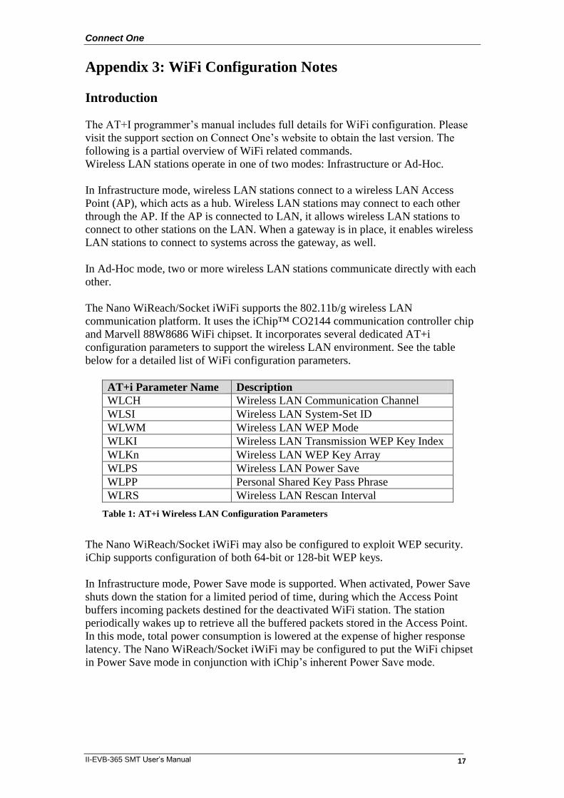
configuration parameters to support the wireless LAN environment. See the table
below for a detailed list of WiFi configuration parameters.
AT+i Parameter Name Description
WLCH Wireless LAN Communication Channel
WLSI Wireless LAN System-Set ID
WLWM Wireless LAN WEP Mode
WLKI Wireless LAN Transmission WEP Key Index
WLKn Wireless LAN WEP Key Array
WLPS Wireless LAN Power Save
WLPP Personal Shared Key Pass Phrase
WLRS Wireless LAN Rescan Interval
Table 1: AT+i Wireless LAN Configuration Parameters
The Nano WiReach/Socket iWiFi may also be configured to exploit WEP security.
iChip supports configuration of both 64-bit or 128-bit WEP keys.
In Infrastructure mode, Power Save mode is supported. When activated, Power Save
shuts down the station for a limited period of time, during which the Access Point
buffers incoming packets destined for the deactivated WiFi station. The station
periodically wakes up to retrieve all the buffered packets stored in the Access Point.
In this mode, total power consumption is lowered at the expense of higher response
latency. The Nano WiReach/Socket iWiFi may be configured to put the WiFi chipset
in Power Save mode in conjunction with iChip’s inherent Power Save mode.
Connect One
II-EVB-365 SMT User’s Manual 18
iChip Wireless LAN Environment Configuration Parameters
WLCH (Factory Default: 0)
In Infrastructure mode, the WLCH parameter must be set to 0. Other available values
(1..13) designate the preferred communication channel while in Ad-Hoc mode.
WLSI (Factory Default: Empty)
This parameter must be assigned with the System-Set-ID string (SSID), which is
identical to that configured in the Access Point(s) through which the WiFi station
needs to connect. An exception to this is the ―Any SSID‖ configuration, which is
configured by simply leaving this parameter empty (or setting to NULL string with
AT+iWLSI=‖‖). In the ―Any SSID‖ configuration, the WiFi station will connect to
any available Access Point. If more than one Access Point is active, it will choose the
one with the stronger radio signal.
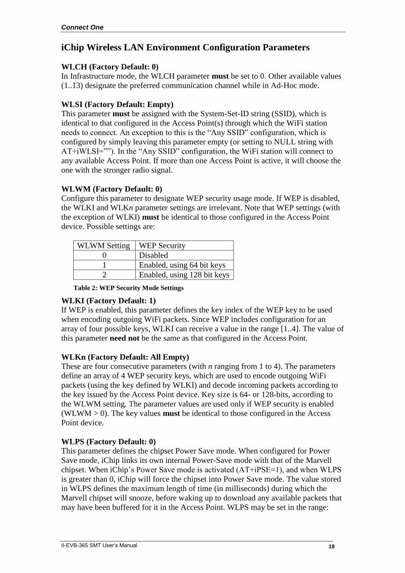
WLWM (Factory Default: 0)
Configure this parameter to designate WEP security usage mode. If WEP is disabled,
the WLKI and WLKn parameter settings are irrelevant. Note that WEP settings (with
the exception of WLKI) must be identical to those configured in the Access Point
device. Possible settings are:
WLWM Setting WEP Security
0 Disabled
1 Enabled, using 64 bit keys
2 Enabled, using 128 bit keys
Table 2: WEP Security Mode Settings
WLKI (Factory Default: 1)
If WEP is enabled, this parameter defines the key index of the WEP key to be used
when encoding outgoing WiFi packets. Since WEP includes configuration for an
array of four possible keys, WLKI can receive a value in the range [1..4]. The value of
this parameter need not be the same as that configured in the Access Point.
WLKn (Factory Default: All Empty)
These are four consecutive parameters (with n ranging from 1 to 4). The parameters
define an array of 4 WEP security keys, which are used to encode outgoing WiFi
packets (using the key defined by WLKI) and decode incoming packets according to
the key issued by the Access Point device. Key size is 64- or 128-bits, according to
the WLWM setting. The parameter values are used only if WEP security is enabled
(WLWM > 0). The key values must be identical to those configured in the Access
Point device.
WLPS (Factory Default: 0)
This parameter defines the chipset Power Save mode. When configured for Power
Save mode, iChip links its own internal Power-Save mode with that of the Marvell
chipset. When iChip’s Power Save mode is activated (AT+iPSE=1), and when WLPS
is greater than 0, iChip will force the chipset into Power Save mode. The value stored
in WLPS defines the maximum length of time (in milliseconds) during which the
Marvell chipset will snooze, before waking up to download any available packets that
may have been buffered for it in the Access Point. WLPS may be set in the range:
Connect One
II-EVB-365 SMT User’s Manual 19
[0..3600]. When WLPS is set to 0, the Marvell chipset Power Save is disabled, even if
iChip enters Power Save mode.
WLPP (Factory Default: Empty)
This parameter sets the wireless LAN WPA1-PSK pass-phrase to be used in
generating the WPA1-PSK encryption key. When empty, WPA security is disabled. If
WLSI (SSID) is not empty, WPA1-PSK security is enabled for WiFi connections and
WLPP is used in generating the WPA1-PSK encryption key. The allowed value for
WLPP is an ASCII string containing 8-63 characters.
WLRS (Factory Default: 0)
This parameter sets the interval between consecutive scans that iChip performs in
search for nearby ad-hoc networks. Scan duration is two beacon periods (200 ms).
WLRS may be set in the range: 0-65535 milliseconds.
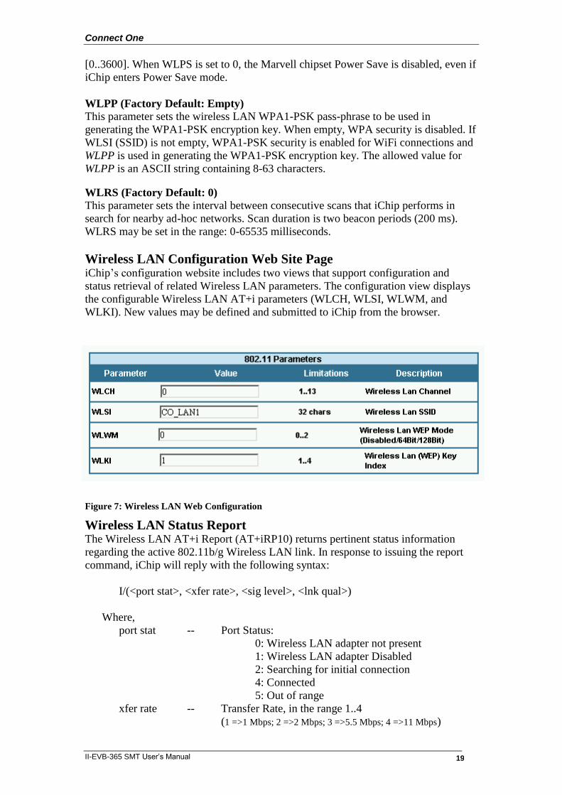
Wireless LAN Configuration Web Site Page iChip’s configuration website includes two views that support configuration and
status retrieval of related Wireless LAN parameters. The configuration view displays
the configurable Wireless LAN AT+i parameters (WLCH, WLSI, WLWM, and
WLKI). New values may be defined and submitted to iChip from the browser.
Figure 7: Wireless LAN Web Configuration
Wireless LAN Status Report The Wireless LAN AT+i Report (AT+iRP10) returns pertinent status information
regarding the active 802.11b/g Wireless LAN link. In response to issuing the report
command, iChip will reply with the following syntax:
I/(<port stat>, <xfer rate>, <sig level>, <lnk qual>)
Where,
port stat -- Port Status:
0: Wireless LAN adapter not present
1: Wireless LAN adapter Disabled
2: Searching for initial connection
4: Connected
5: Out of range
xfer rate -- Transfer Rate, in the range 1..4
(1 =>1 Mbps; 2 =>2 Mbps; 3 =>5.5 Mbps; 4 =>11 Mbps)

Connect One
II-EVB-365 SMT User’s Manual 20
sig lvl -- Signal Level [%], in the range 0..100
lnk qual -- Link Quality [%], in the range 0..100
The Configuration website contains a live status page with this and some additional
status information:
Figure 8: Wireless LAN Web Status Display
iChip Wireless LAN Test Mode
WLTR
This command limits the wireless LAN transmission rate according to the specified
command parameter. The table below details the possible parameter values:
Maximum
Transmission Rate
Detail
0 Maximum possible transmission rate for the current chipset.
1 1 Mbps
2 2 Mbps
3 5.5 Mbps
4 11 Mbps
5 Reserved
6 6 Mbps
7 9 Mbps
8 12 Mbps
9 18 Mbps
10 24 Mbps
11 36 Mbps
12 48 Mbps
13 54 Mbps
Table 3: Maximum Transmission Rate Command Parameter
Connect One
II-EVB-365 SMT User’s Manual 21
When AT+i WLTR is issued, transmission rate is limited for the duration of the
session until another AT+iWLTR command is issued, or iChip is power-cycled.
Placement and Range Guidelines 802.11b/g wireless LAN devices connect to wireless LAN Access Points over a
maximum range of 300 feet. Actual transmission rate and service quality may vary
significantly as a result of environmental obstacles and physical placement of the
Access Point and station devices.
For best results, refer to the following guidelines:
1. Locate the wireless LAN equipment away from sources of interference, such
as PCs, large metal surfaces, microwaves, and cordless phones.
2. Position the wireless LAN access point at an elevated position and as close as
possible to the center of the area in which the wireless LAN devices will
operate.
Wireless LAN Data Privacy/Security Considerations The fact that wireless LAN devices transmit data over a radio link makes them
vulnerable to electronic eavesdropping, tampering, and information theft. There are
several means by which you may strengthen your wireless LAN access security:
Change the factory default SSID setting of the wireless LAN Access Point and
station devices. Enable WEP or WPA encryption of the wireless LAN data
communications. If you use WEP, it is recommended that you use 128-bit
WEP keys.
Restrict 802.11b/g wireless LAN access based on MAC address. This is
configurable in most Access Point devices.
Place the 802.11b/g Wireless Access Point in a location where it cannot be
physically tampered with.
Store printed SSID and WEP or WPA key settings in a safe place.
For a complete Wireless LAN Configuration Guide for iChip products download the
―WiFi Configuration Guide‖ form the Connect One Web site at:
http://www.connectone.com/support.asp?did=42.
Connect One
II-EVB-365 SMT User’s Manual 22
Appendix 4: SPI Host Interface
Introduction The Nano WiReach/Socket iWiFi contains an SPI slave port, which allows a Host
processor to interface the iChip using an SPI Master port.
The SPI data transfer shall be based on the 'Command-Response' principle. (Half
Duplex). Meaning, until the HOST gets an answer to a command, it won't send a
new one.
Several assumptions have been made:
Number of bits per transfer is: 8.
No echo from the module to HOST (i.e. when module’s host interface is
set to SPI, the command AT+iEn is meaningless.
When module’s host interface is set to SPI, the module won't support
SerialNet mode since it is not Half Duplex compatible.
When module’s host interface is set to SPI, the module won't support the
―+++‖ Escape sequence.
The SPI interface will have the following behavior:
Fixed peripheral select
The CS is directly connected to the SPI Master device
Mode fault detection is enabled
The inactive state value of the serial clock is logic level zero
Data is changed on the leading edge of the serial clock and captured on the
following edge of the serial clock
The peripheral chip select line rises as soon as the last transfer is achieved
SPI Protocol A module GPIO Output signal is dedicated as the SPI Control signal (nSPI_INT).
After receiving a command from the Host, the module will assert this signal for the
duration of its response. The Host should not attempt to send the next command until
this signal is de-asserted. The SPI control signal pin is defined with the new +iSPIP
parameter described below.
The SPI control signal is also utilized as a flow-control signal when the Host transmits
data to the module.
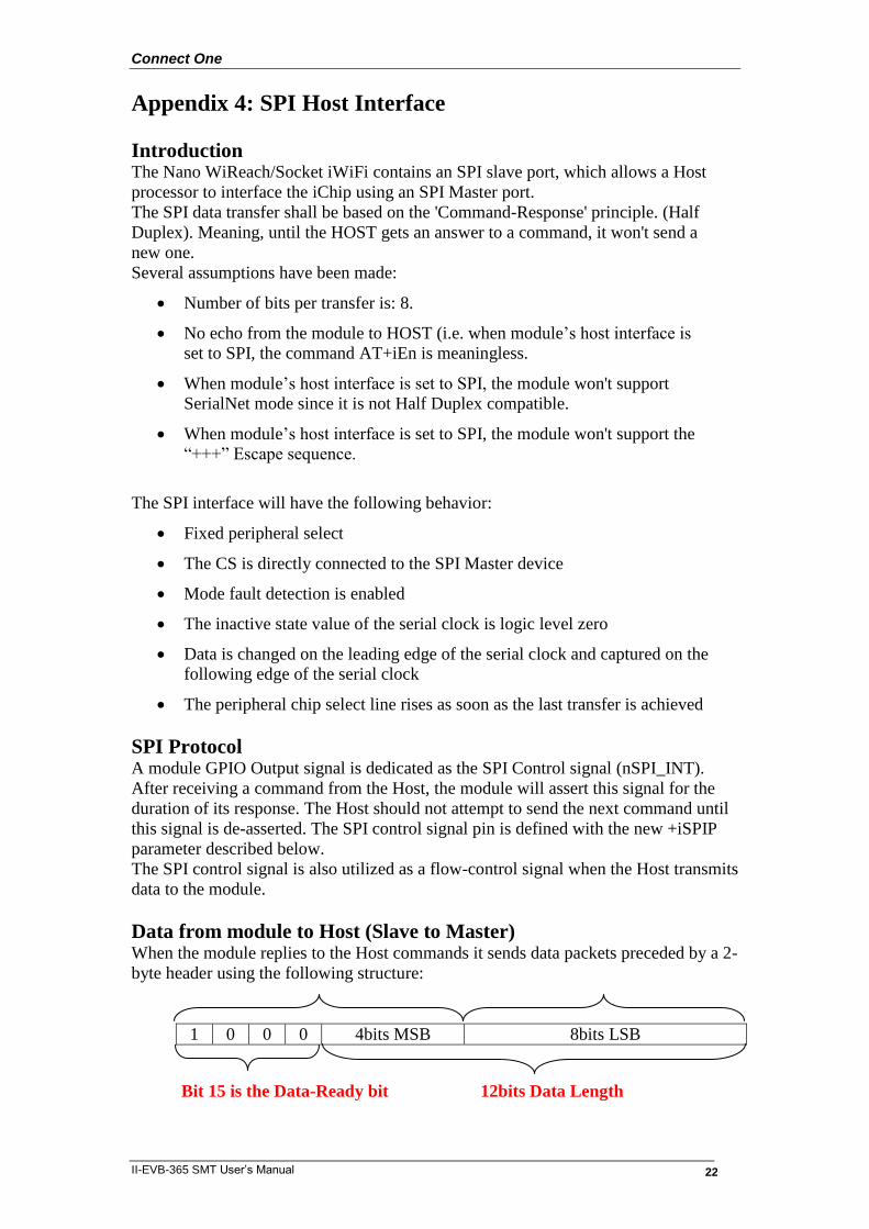
Data from module to Host (Slave to Master) When the module replies to the Host commands it sends data packets preceded by a 2-
byte header using the following structure:
1 0 0 0 4bits MSB 8bits LSB
Bit 15 is the Data-Ready bit 12bits Data Length

Connect One
II-EVB-365 SMT User’s Manual 23
The module’s SPI driver asserts the SPI Control GPIO to indicate to the host to
start reading the entire packet, starting with the header word and followed by the
packet payload, whose length matches the 12 LSBits of the Header word.
All the received bytes from the host are ignored.
Flow Control - Data from Host to iChip Flow Control Flow control from the module to the host is managed using the SPI control signal.
The module will assert the SPI Control signal to signal flow stop.
As soon as the host identifies that the SPI control signal was asserted it should
stop transmitting. When the module can resume reception, it will de-assert the SPI
Control signal.
iSPIP — SPI GPIO Pin Syntax: AT+iSPIP=<n>
Define a GPIO as the SPI Control signal
Parameters:
n=0 SPI Control Signal is disabled
n=1..6 Use PIOC [<n>-1] as the SPI Control signal
Default: 0 – SPI Control signal disabled
Result code:
I/OK If n is a legal value.
I/ERROR Otherwise
AT+iSPIP? Returns the current SPIP value followed by I/OK.
AT+iSPIP=? Returns the message “0-6” followed by I/OK.
Note: The setting will take effect only after SW or HW reset.
iHIF — Host Interface The +iHIF (Host Interface) parameter is used to define if the SPI Host interface is to
be used. A new value of 6 defines usage of SPI.
For example, AT+iHIF=6 -- Selects SPI as the Host module interface.