Embed Size (px)
DESCRIPTION
Ihe Iti Tf Vol2xIHEITI
Citation preview
Copyright © 2014: IHE International, Inc.
Integrating the Healthcare Enterprise
IHE IT Infrastructure 5
Technical Framework
Volume 2x IHE ITI TF-2x
Volume 2 Appendices 10
15
Revision 11.0 – Final Text 20
September 23, 2014
Please verify you have the most recent version of this document, which is published here. 25
IHE IT Infrastructure Technical Framework, Volume 2x (ITI TF-2x): Appendices ______________________________________________________________________________
_____________________________________________________________________________ Rev. 11.0 Final Text – 2014-09-23 2 Copyright © 2014: IHE International, Inc.
CONTENTS
Appendix A: Web Service Definition for Retrieve Specific Information for Display and 30
Retrieve Document for Display Transaction.............................................................................. 5 Appendix B: Definition of Document Unique Ids ................................................................... 13
B.1: Requirements for Document UIDs ................................................................................... 13 B.2: Structure of a Document UID ........................................................................................... 13 B.3: Document UID encoding rules ......................................................................................... 13 35 B.4: How to obtain a UID registration root? ............................................................................ 14 B.5: Example of a Document UID ........................................................................................... 14 B.6: Representing UUIDs as OIDs ........................................................................................... 15
Appendix C: HL7 Profiling Conventions ................................................................................ 16 C.1: HL7 Message Profiling Convention ................................................................................. 17 40
C.1.1: Static definition - Message level ........................................................................ 17 C.1.2: Static definition – Segment level and Data Type level ...................................... 18
C.2: HL7 Implementation Notes............................................................................................... 19 C.2.1: Network Guidelines ............................................................................................ 19 C.2.2: Message Control ................................................................................................. 19 45 C.2.3: Acknowledgment Modes .................................................................................... 21 C.2.4: Common Segment Definitions ........................................................................... 24 C.2.5: Message granularity ............................................................................................ 25 C.2.6: HL7 empty field convention ............................................................................... 25
Appendix D: Cross-Profile Interactions of PIX and PSA ........................................................ 26 50 D.1: Namespace Translation from PIX Query to CCOW......................................................... 27 D.2: Processing Multiple Identifiers ......................................................................................... 28
Appendix E: Usage of the CX Data Type in PID-3-Patient Identifier List ............................. 30 E.1: Patient Identifier Cross-reference Manager Actor Requirements ..................................... 31
E.1.2: Other actor requirements ........................................................................................... 32 55 E.1.3: Examples of use ......................................................................................................... 33 E.1.4: Data sent by source systems ...................................................................................... 33 E.1.5: Data sent by the Patient Identifier Cross-reference Manager .................................... 34
E.2: HL7 V3 II Data Type ........................................................................................................ 35 E.2.1: Patient Identifier Cross-reference Manager requirements ......................................... 36 60 E.2.2: Other actor requirements ........................................................................................... 37 E.2.3: Examples of use ......................................................................................................... 37
Appendix F: Character String Comparisons ............................................................................ 40 Appendix G: Transition from Radiology Basic Security to ATNA ......................................... 41 Appendix H: Intentionally Left Blank ..................................................................................... 42 65 Appendix I: Intentionally Left Blank ..................................................................................... 43 Appendix J: Intentionally Left Blank ..................................................................................... 44 Appendix K: XDS Security Environment ................................................................................ 45
K.1: Security Environment ....................................................................................................... 45 K.1.1: Threats ................................................................................................................ 45 70
IHE IT Infrastructure Technical Framework, Volume 2x (ITI TF-2x): Appendices ______________________________________________________________________________
_____________________________________________________________________________ Rev. 11.0 Final Text – 2014-09-23 3 Copyright © 2014: IHE International, Inc.
K.1.2: Security and Privacy Policy ................................................................................ 46 K.1.3: Security Usage Assumptions .............................................................................. 48
K.2: Security Objectives ........................................................................................................... 48 K.2.1: XDS Component Security Objectives ................................................................ 48 K.2.2: Environment Security Objectives ....................................................................... 50 75
K.3: Functional Environment.................................................................................................... 50 Appendix L: Relationship of Document Entry Attributes and Document Headers ................ 53 Appendix M: Using Patient Demographics Query in a Multi-Domain Environment .............. 54
M.1: HL7 QBP^Q22 Conformance Model ........................................................................ 54 M.2: IHE PDQ Architecture ............................................................................................... 54 80 M.3: Implementing PDQ in a multi-domain architecture .................................................. 55
Appendix N: Common Data Types .......................................................................................... 57 N.1: CX Data Type ................................................................................................................... 57 N.2: EI Data Type ..................................................................................................................... 57 N.3: HD Data Type ................................................................................................................... 58 85 N.4: PL data Type ..................................................................................................................... 58 N.5: TS Data Type .................................................................................................................... 60 N.6: XPN Data Type ................................................................................................................. 60
Appendix O: HL7 v3 Transmission and Trigger Event Control Act Wrappers ....................... 62 O.1: HL7 V3 Transmission Wrappers ...................................................................................... 62 90
O.1.1: Send Message Payload Information Model (MCCI_RM000100IHE) ............... 62 O.1.2: Send Accept Acknowledgement Information Model (MCCI_RM000200IHE) 65 O.1.3: Send Application Acknowledgement Information Model
(MCCI_RM000300IHE)............................................................................................ 69 O.2: HL7 V3 Transmission Content ......................................................................................... 72 95
O.2.1: Master File/Registry Event Notification Control Act (Role Subject) Information Model (MFMI_MT700701IHE) ................................................................................ 73
O.2.2: Master File/Registry Query Response Control Act (Role Subject) Information Model (MFMI_MT700711IHE) ................................................................................ 76
O.2.3: Query Control Act Request: Query By Parameter Information Model 100 (QUQI_MT021001IHE) ............................................................................................ 80
O.2.4: Query Control Act Request Continue/Cancel Information Model (QUQI_MT000001IHE) ............................................................................................ 82
O.3: IHE Transactions and Corresponding Transmission and Control Act Wrappers ............. 83 Appendix P: Examples of messages ........................................................................................ 85 105
P.1: Example of transaction ITI-31: Admit for Surgical Procedure ........................................ 85 P.1.1: Storyboard .................................................................................................................. 85 P.1.2: Interaction Diagram ................................................................................................... 86 P.1.3: Messages .................................................................................................................... 88
P.2: Example of transaction ITI-31: Admit and cancel admit.................................................. 90 110 P.2.1: Storyboard .................................................................................................................. 90 P.2.2: Interaction Diagram ................................................................................................... 91 P.2.3: Messages .................................................................................................................... 91
P.3: HL7 V3 Sample Messages ................................................................................................ 92 P.3.1: ITI-44 Patient Identity Feed HL7 V3 – Sample Messages ........................................ 92 115
IHE IT Infrastructure Technical Framework, Volume 2x (ITI TF-2x): Appendices ______________________________________________________________________________
_____________________________________________________________________________ Rev. 11.0 Final Text – 2014-09-23 4 Copyright © 2014: IHE International, Inc.
P.3.2: ITI 45 PIXV3 Query – Sample Messages ................................................................. 92 P.3.3: ITI 46 PIXV3 Update Notification – Sample Messages ........................................... 93 P.3.4: ITI 47 Patient Demographics Query HL7 V3 – Sample Messages ........................... 93
Appendix Q: HL7 V3 Sample Payload XML Schemas ........................................................... 94 Q.1: ITI-44 Patient Identity Feed HL7 V3 – Sample Schemas ................................................ 94 120 Q.2: ITI-45 PIXV3 Query – Sample Schemas.......................................................................... 94 Q.3: ITI-46 PIXV3 Update Notification – Sample Schemas .................................................... 94 Q.4: ITI-47 Patient Demographics Query HL7 V3 – Sample Schemas ................................... 94
Appendix R: Mapping of HL7v2.5 to HL7v3 for PIX and PDQ ............................................. 96 R.1: Data Types ........................................................................................................................ 96 125 R.2: Add New Person Message ................................................................................................ 98
Appendix S: Intentionally Left Blank ................................................................................... 120 Appendix T: Use of eMail (Informative) ............................................................................... 121 Appendix U: Intentionally Left Blank ................................................................................... 124 Appendix V: Web Services for IHE Transactions ................................................................. 125 130
V.1: Introduction ..................................................................................................................... 125 V.2: Relevant Standards.......................................................................................................... 125
V.2.1: WS-I Profiles .................................................................................................... 125 V.2.2: WS-* Specifications ......................................................................................... 125 V.2.3: HL7 Web Services Profile ................................................................................ 126 135 V.2.4: XML Namespaces ............................................................................................ 126
V.3: Web Services Requirements ........................................................................................... 126 V.3.1: Requirements for Transactions using HL7 V3 Messages ................................ 127 V.3.2: Requirements for Transactions which don’t use HL7 V3 Messages ............... 128
V.4: Web Services for specific IHE Transactions .................................................................. 137 140 V.5: Synchronous and Asynchronous Web Services Exchange ............................................. 137
V.5.1: Overview .......................................................................................................... 137 V.5.2: Considerations for using Asynchronous Web Services Exchange ................... 137 V.5.3: Specification of the use of Asynchronous Web Services Exchange ................ 138
V.6: Web Services Standards Evolution ................................................................................. 138 145 V.7: Web Services References ................................................................................................ 139
Appendix W: Implementation Material .................................................................................. 140 GLOSSARY ............................................................................................................................... 141
150
IHE IT Infrastructure Technical Framework, Volume 2x (ITI TF-2x): Appendices ______________________________________________________________________________
_____________________________________________________________________________ Rev. 11.0 Final Text – 2014-09-23 5 Copyright © 2014: IHE International, Inc.
Appendix A: Web Service Definition for Retrieve Specific Information for Display and Retrieve Document for Display Transaction The following is an example WSDL definition of web services used in Transactions ITI-11 and 155 ITI-12. This code is provided as an example and is not intended to replace the formal specification of Transactions ITI-11 and ITI-12 in Volume 2a. Also, the definitions of summaryRequestType, listRequestType and contentType shall correspond to the capabilities of the Information Source Actor. 160 <?xml version="1.0" encoding="utf8"?> <definitions xmlns:http="http://schemas.xmlsoap.org/wsdl/http/" xmlns:s="http://www.w3.org/2001/XMLSchema" xmlns:s0="http://rsna.org/ihe/IHERetrieveForDisplay" 165 xmlns:tm="http://microsoft.com/wsdl/mime/textMatching/" xmlns:mime="http://schemas.xmlsoap.org/wsdl/mime/" targetNamespace="http://rsna.org/ihe/IHERetrieveForDisplay" xmlns="http://schemas.xmlsoap.org/wsdl/"> 170 <!-- Defines the types available for the parameters --> <!-- May also include the return type definitions --> <types> <s:schema elementFormDefault="qualified" targetNamespace="http://rsna.org/ihe/IHERetrieveForDisplay"> 175 <!-- Add any items that control the returned values list or type here --> <!-- Add or remove items in the actual supplied WSDL to show the available types. --> <s:simpleType name="summaryRequestType"> 180 <s:restriction base="s:string"> <s:enumeration value="SUMMARY" /> <s:enumeration value="SUMMARY-RADIOLOGY" /> <s:enumeration value="SUMMARY-CARDIOLOGY" /> <s:enumeration value="SUMMARY-LABORATORY" /> 185 <s:enumeration value="SUMMARY-SURGERY" /> <s:enumeration value="SUMMARY-EMERGENCY" /> <s:enumeration value="SUMMARY-DISCHARGE" /> <s:enumeration value="SUMMARY-ICU" /> </s:restriction> 190 </s:simpleType> <s:simpleType name="listRequestType"> <s:restriction base="s:string"> <s:enumeration value="LIST-ALLERGIES" /> 195 <s:enumeration value="LIST-MEDS" /> </s:restriction> </s:simpleType> <!-- Please list all content types available, and remove those not 200 available. --> <s:simpleType name="contentType">
IHE IT Infrastructure Technical Framework, Volume 2x (ITI TF-2x): Appendices ______________________________________________________________________________
_____________________________________________________________________________ Rev. 11.0 Final Text – 2014-09-23 6 Copyright © 2014: IHE International, Inc.
<s:restriction base="s:string"> <s:enumeration value="text/html" /> </s:restriction> 205 </s:simpleType> <!-- Indicates that this item is a returned rows restriction --> <s:simpleType name="ReturnedResultCount" type="s:positiveInteger" /> 210 <!-- Please use the string "Search" as a prefix for all search criteria, and list below --> <!-- Indicates that this item is a search string --> <s:simpleType name="SearchString" type="s:string" /> 215 </s:schema> </types> 220 <message name="RetrieveSummaryInfoHttpGetIn"> <!-- Add other parameters here if they are available, using types defined above. --> <part name="requestType" type="summaryRequestType" /> <part name="patientID" type="SearchString" /> 225 <part name="lowerDateTime" type="s:dateTime" /> <part name="upperDateTime" type="s:dateTime" /> <part name="mostRecentResults" type="ReturnedResultCount" /> </message> 230 <message name="RetrieveSummaryInfoHttpGetOut"> <!-- If a complex type is defined for the return value, then it is suggested that --> <!-- it be used here instead of s0:string. If a complex type is allowed as one --> 235 <!-- of the options, but an arbitrarily formatted string is also allowed, then create --> <!-- a union type here that allows either option. --> <part name="Body" element="s0:string" /> </message> 240 <message name="RetrieveListInfoHttpGetIn"> <!-- Add other parameters here if they are available, using types defined above. --> <part name="requestType" type="listRequestType" /> 245 <part name="patientID" type="SearchString" /> </message> <message name="RetrieveListInfoHttpGetOut"> <!-- If a complex type is defined for the return value, then it is 250 suggested that --> <!-- it be used here instead of s0:string. If a complex type is allowed as one --> <!-- of the options, but an arbitrarily formatted string is also allowed, then create --> 255 <!-- a union type here that allows either option. --> <part name="Body" element="s0:string" />
IHE IT Infrastructure Technical Framework, Volume 2x (ITI TF-2x): Appendices ______________________________________________________________________________
_____________________________________________________________________________ Rev. 11.0 Final Text – 2014-09-23 7 Copyright © 2014: IHE International, Inc.
</message> <message name="RetrieveDocumentHttpGetIn"> <!-- Add other parameters here if they are available, using types defined 260 above. --> <!-- It is recommended that one of the sub-types of SearchUID is chosen here --> <!-- Especially if SearchStudyUID is allowed, then the display client can 265 know that --> <!-- it is permissible to use a dicom uid here --> <part name="documentUID" type="SearchString" /> <part name="contentType" type="contentType" /> </message> 270 <message name="RetrieveDocumentHttpGetOut"> <!-- If a complex type is defined for the return value, then it is suggested that --> <!-- it be used here instead of s:string. If a complex type is allowed as 275 one --> <!-- of the options, but an arbitrarily formatted string is also allowed, then create --> <!-- a union type here that allows either option. --> <part name="Body" element="s:string" /> 280 </message> <portType name="IHERetrieveForDisplayHttpGet"> <operation name="RetrieveSummaryInfo"> <input message="s0:RetrieveSummaryInfoHttpGetIn" /> 285 <output message="s0:RetrieveSummaryInfoHttpGetOut" /> </operation> <operation name="RetrieveListInfo"> <input message="s0:RetrieveListInfoHttpGetIn" /> <output message="s0:RetrieveListInfoHttpGetOut" /> 290 </operation> <operation name="RetrieveDocument"> <input message="s0:RetrieveDocumentHttpGetIn" /> <output message="s0:RetrieveDocumentHttpGetOut" /> </operation> 295 </portType> <binding name="IHERetrieveForDisplayHttpGet" type="s0:IHERetrieveForDisplayHttpGet"> <http:binding verb="GET" /> 300 <operation name="RetrieveSummaryInfo"> <http:operation location="/IHERetrieveSummaryInfo" /> <input> <http:urlEncoded /> </input> 305 <output> <mime:content type="text/html" /> </output> </operation> 310 <operation name="RetrieveListInfo">
IHE IT Infrastructure Technical Framework, Volume 2x (ITI TF-2x): Appendices ______________________________________________________________________________
_____________________________________________________________________________ Rev. 11.0 Final Text – 2014-09-23 8 Copyright © 2014: IHE International, Inc.
<http:operation location="/IHERetrieveListInfo" /> <input> <http:urlEncoded /> 315 </input> <output> <mime:content type="text/html" /> </output> 320 </operation> <operation name="RetrieveDocument"> <http:operation location="/IHERetrieveDocument" /> <input> 325 <http:urlEncoded /> </input> <!-- The type of the output should be restricted on a per-server basis to the types --> 330 <!-- actually provided. --> <output> <mime:content type="text/html" /> <mime:content type="application/x-hl7-cda-level-one+xml" /> <mime:content type="application/pdf" /> 335 <mime:content type="image/jpeg" /> </output> </operation> </binding> 340 <!-- Bind the actual service here --> <service name="IHERetrieveForDisplay"> <port name="IHERetrieveForDisplayHttpGet" binding="s0:IHERetrieveForDisplayHttpGet"> <http:address location="http://localhost/" /> 345 </port> </service> <?xml version="1.0" encoding="utf8"?> <definitions xmlns:http="http://schemas.xmlsoap.org/wsdl/http/" 350 xmlns:s="http://www.w3.org/2001/XMLSchema" xmlns:s0="http://rsna.org/ihe/IHERetrieveForDisplay" xmlns:tm="http://microsoft.com/wsdl/mime/textMatching/" xmlns:mime="http://schemas.xmlsoap.org/wsdl/mime/" targetNamespace="http://rsna.org/ihe/IHERetrieveForDisplay" 355 xmlns="http://schemas.xmlsoap.org/wsdl/"> <!-- Defines the types available for the parameters --> <!-- May also include the return type definitions --> <types> 360 <s:schema elementFormDefault="qualified" targetNamespace="http://rsna.org/ihe/IHERetrieveForDisplay"> <!-- Add any items that control the returned values list or type here --> <!-- Add or remove items in the actual supplied WSDL to show the 365 available types. --> <s:simpleType name="summaryRequestType">
IHE IT Infrastructure Technical Framework, Volume 2x (ITI TF-2x): Appendices ______________________________________________________________________________
_____________________________________________________________________________ Rev. 11.0 Final Text – 2014-09-23 9 Copyright © 2014: IHE International, Inc.
<s:restriction base="s:string"> <s:enumeration value="SUMMARY" /> <s:enumeration value="SUMMARY-RADIOLOGY" /> 370 <s:enumeration value="SUMMARY-CARDIOLOGY" /> <s:enumeration value="SUMMARY-LABORATORY" /> <s:enumeration value="SUMMARY-SURGERY" /> <s:enumeration value="SUMMARY-EMERGENCY" /> <s:enumeration value="SUMMARY-DISCHARGE" /> 375 <s:enumeration value="SUMMARY-ICU" /> <s:enumeration value="SUMMARY-RX" /> </s:restriction> </s:simpleType> 380 <s:simpleType name="listRequestType"> <s:restriction base="s:string"> <s:enumeration value="LIST-ALLERGIES" /> <s:enumeration value="LIST-MEDS" /> </s:restriction> 385 </s:simpleType> <!-- Please list all content types available, and remove those not available. --> <s:simpleType name="contentType"> 390 <s:restriction base="s:string"> <s:enumeration value="text/html" /> </s:restriction> </s:simpleType> 395 <!-- Indicates that this item is a returned rows restriction --> <s:simpleType name="ReturnedResultCount" type="s:positiveInteger" /> <!-- Please use the string "Search" as a prefix for all search criteria, and list below --> 400 <!-- Indicates that this item is a search string --> <s:simpleType name="SearchString" type="s:string" /> 405 </s:schema> </types> <message name="RetrieveSummaryInfoHttpGetIn"> <!-- Add other parameters here if they are available, using types defined 410 above. --> <part name="requestType" type="summaryRequestType" /> <part name="patientID" type="SearchString" /> <part name="lowerDateTime" type="s:dateTime" /> <part name="upperDateTime" type="s:dateTime" /> 415 <part name="mostRecentResults" type="ReturnedResultCount" /> </message> <message name="RetrieveSummaryInfoHttpGetOut"> <!-- If a complex type is defined for the return value, then it is 420 suggested that -->
IHE IT Infrastructure Technical Framework, Volume 2x (ITI TF-2x): Appendices ______________________________________________________________________________
_____________________________________________________________________________ Rev. 11.0 Final Text – 2014-09-23 10 Copyright © 2014: IHE International, Inc.
<!-- it be used here instead of s0:string. If a complex type is allowed as one --> <!-- of the options, but an arbitrarily formatted string is also allowed, then create --> 425 <!-- a union type here that allows either option. --> <part name="Body" element="s0:string" /> </message> <message name="RetrieveListInfoHttpGetIn"> 430 <!-- Add other parameters here if they are available, using types defined above. --> <part name="requestType" type="listRequestType" /> <part name="patientID" type="SearchString" /> </message> 435 <message name="RetrieveListInfoHttpGetOut"> <!-- If a complex type is defined for the return value, then it is suggested that --> <!-- it be used here instead of s0:string. If a complex type is allowed 440 as one --> <!-- of the options, but an arbitrarily formatted string is also allowed, then create --> <!-- a union type here that allows either option. --> <part name="Body" element="s0:string" /> 445 </message> <message name="RetrieveDocumentHttpGetIn"> <!-- Add other parameters here if they are available, using types defined above. --> 450 <!-- It is recommended that one of the sub-types of SearchUID is chosen here --> <!-- Especially if SearchStudyUID is allowed, then the display client can know that --> <!-- it is permissible to use a dicom uid here --> 455 <part name="documentUID" type="SearchString" /> <part name="contentType" type="contentType" /> </message> <message name="RetrieveDocumentHttpGetOut"> 460 <!-- If a complex type is defined for the return value, then it is suggested that --> <!-- it be used here instead of s:string. If a complex type is allowed as one --> <!-- of the options, but an arbitrarily formatted string is also allowed, 465 then create --> <!-- a union type here that allows either option. --> <part name="Body" element="s:string" /> </message> 470 <portType name="IHERetrieveForDisplayHttpGet"> <operation name="RetrieveSummaryInfo"> <input message="s0:RetrieveSummaryInfoHttpGetIn" /> <output message="s0:RetrieveSummaryInfoHttpGetOut" /> </operation> 475 <operation name="RetrieveListInfo">
IHE IT Infrastructure Technical Framework, Volume 2x (ITI TF-2x): Appendices ______________________________________________________________________________
_____________________________________________________________________________ Rev. 11.0 Final Text – 2014-09-23 11 Copyright © 2014: IHE International, Inc.
<input message="s0:RetrieveListInfoHttpGetIn" /> <output message="s0:RetrieveListInfoHttpGetOut" /> </operation> <operation name="RetrieveDocument"> 480 <input message="s0:RetrieveDocumentHttpGetIn" /> <output message="s0:RetrieveDocumentHttpGetOut" /> </operation> </portType> 485 <binding name="IHERetrieveForDisplayHttpGet" type="s0:IHERetrieveForDisplayHttpGet"> <http:binding verb="GET" /> <operation name="RetrieveSummaryInfo"> <http:operation location="/IHERetrieveSummaryInfo" /> 490 <input> <http:urlEncoded /> </input> <output> 495 <mime:content type="text/html" /> </output> </operation> <operation name="RetrieveListInfo"> 500 <http:operation location="/IHERetrieveListInfo" /> <input> <http:urlEncoded /> </input> 505 <output> <mime:content type="text/html" /> </output> </operation> 510 <operation name="RetrieveDocument"> <http:operation location="/IHERetrieveDocument" /> <input> <http:urlEncoded /> </input> 515 <!-- The type of the output should be restricted on a per-server basis to the types --> <!-- actually provided. --> <output> 520 <mime:content type="text/html" /> <mime:content type="application/x-hl7-cda-level-one+xml" /> <mime:content type="application/pdf" /> <mime:content type="image/jpeg" /> </output> 525 </operation> </binding> <!-- Bind the actual service here --> <service name="IHERetrieveForDisplay"> 530
IHE IT Infrastructure Technical Framework, Volume 2x (ITI TF-2x): Appendices ______________________________________________________________________________
_____________________________________________________________________________ Rev. 11.0 Final Text – 2014-09-23 12 Copyright © 2014: IHE International, Inc.
<port name="IHERetrieveForDisplayHttpGet" binding="s0:IHERetrieveForDisplayHttpGet"> <http:address location="http://localhost/" /> </port> </service> 535
IHE IT Infrastructure Technical Framework, Volume 2x (ITI TF-2x): Appendices ______________________________________________________________________________
_____________________________________________________________________________ Rev. 11.0 Final Text – 2014-09-23 13 Copyright © 2014: IHE International, Inc.
Appendix B: Definition of Document Unique Ids The Retrieve Information for Display Integration Profile in its Retrieve Persistent Document transaction relies on a globally unique identification of persistent objects. It is the Information 540 Source Actor’s responsibility, when a specific document instance is available for retrieval, to assign to this document instance a globally unique identifier, thus allowing Display Actors to retrieve the same document instance at different points in time and to obtain the same semantics for its presented content. This appendix describes how unique identifiers for documents shall be created. A unique 545 identifier may be created by the Information Source Actor or by any other system to which the information source is connected. The requirements specified in this appendix are derived from the common practices and definitions of OIDs in ISO 8824, HL7 V3 and CDA and UIDs in DICOM. They guarantee uniqueness across multiple countries, sites, vendors and equipment.
B.1: Requirements for Document UIDs 550
The UID identification scheme is based on the OSI Object Identification (numeric form) as defined by the ISO 8824 standard. All Unique Identifiers, used within the context of this transaction shall be registered values as defined by ISO 9834-3 to ensure global uniqueness. These requirements result in the following structure for unique Ids. 555
B.2: Structure of a Document UID Each Document UID is composed of two parts, an <org root> and a <suffix> separated by a “period”. Therefore: UID = <org root>.<suffix> The <org root> portion of the UID uniquely identifies an organization, (e.g., manufacturer, research organization, hospital, etc.), and is composed of a number of numeric components as 560 defined by ISO 8824. The <suffix> portion of the UID is also composed of a number of numeric components, and shall be unique within the scope of the <org root>. This implies that the organization identified in the <org root> is responsible for guaranteeing <suffix> uniqueness by providing registration policies. These policies shall guarantee <suffix> uniqueness for all UID's created by that organization. Unlike the <org root>, which may be common for UID's in an 565 organization, the <suffix> shall take different unique values between different UID's that identify different objects. The <org root> is used only for uniqueness and not for any other purpose. Although a specific implementation may choose some particular structure for its generated UIDs, it should never assume that a UID carries any semantics. A UID shall not be "parsed" to find a particular value or component. Component definition (for the suffix) is implementation-specific 570 and may change as long as uniqueness is maintained. Parsing UID's (including extracting the root) may jeopardize the ability to inter-operate as implementations evolve.
B.3: Document UID encoding rules The UID encoding rules are defined as follows:
IHE IT Infrastructure Technical Framework, Volume 2x (ITI TF-2x): Appendices ______________________________________________________________________________
_____________________________________________________________________________ Rev. 11.0 Final Text – 2014-09-23 14 Copyright © 2014: IHE International, Inc.
• Each component of a UID is a number and shall consist of one or more digits. The first 575 digit of each component shall not be zero unless the component is a single digit.
Note: Registration authorities may distribute components with non-significant leading zeroes. The leading zeroes should be ignored when being encoded (i.e., “00029” would be encoded “29”).
• Each component numeric value shall be encoded using the characters 0-9 of the Basic G0 Set of the International Reference Version of ISO 646:1990. This particular encoding is 580 the same as the UTF-8 encoding for these characters in UNICODE.
• Components shall be separated by the character "." (2EH).
• UIDs shall not exceed 64 total characters, including the digits of each component, and separators between components.
B.4: How to obtain a UID registration root? 585
Organizations that define UIDs are responsible for properly registering their UIDs (at least obtain a registered <Org Root>) as defined for OSI Object Identifiers (ISO 9834-3). The organization defining the UID shall accept the responsibility of ensuring its uniqueness. IHE will not register UIDs or issue registered organization roots. There are a large number of means to obtain free or for a reasonable fee an organization root. 590 A useful resource that is often used by the DICOM community lists the many ways to obtain a registered UID Root for a small fee or even for free, anywhere in the world. http://www.dclunie.com/medical-image-faq/html/part8.html#UIDRegistration The manner in which the suffix of a Document UID is defined is not constrained by any IHE Integration Profile. Only the guarantee of its uniqueness by the defining organization is required 595 by IHE.
B.5: Example of a Document UID This example presents a particular choice made by a specific organization in defining its suffix to guarantee uniqueness. A variant is discussed. "1.2.840.xxxxx.4076078054086.11059664469.235212" 600 (root) (suffix) In this example, the root is: 1 Identifies ISO 2 Identifies ANSI Member Body 840 Country code of a specific Member Body (U.S. for ANSI) 605 xxxxx Identifies a specific Organization (provided by ANSI) In this example the remaining components of the suffix relate to the identification of a specific document instance: 4076078054086 802.3 MAC Address (004 076 078 054 086)
IHE IT Infrastructure Technical Framework, Volume 2x (ITI TF-2x): Appendices ______________________________________________________________________________
_____________________________________________________________________________ Rev. 11.0 Final Text – 2014-09-23 15 Copyright © 2014: IHE International, Inc.
11059664469 Time system was booted (July 31, 2033 10:14:29) 610 235212 Monotonically increasing sequence number In this example, the organization has chosen these components to guarantee uniqueness. Other organizations may choose an entirely different series of components to uniquely identify its documents. Because of the flexibility allowed in creating Document UIDs, implementations should not 615 depend on any assumed structure of UIDs and should not attempt to parse UIDs to extract the semantics of some of its components.
B.6: Representing UUIDs as OIDs The standards ITU X.667 and ISO 9834-8 defined a particular OID root for the UUIDs, and define the translation between these two formats. The top node 2.25 is assigned for all UUIDs. 620 This means that the UUID that can be written as urn:uuid:f81d4fae-7dec-11d0-a765-00a0c91e6bf6 (using hexadecimal notation) is also 2.25.329800735698586629295641978511506172918 (using dotted decimal notation). It can also be encoded using the ASN.1 rules in a binary form internally within X.509 Certificates and some LDAP messages. All of these are the same OID. The reverse is not true. Not all OIDs can be 625 represented as UUIDs. UUIDs are a subset of the OIDs. This relationship is one way to obtain OIDs in situations where an OID is needed. It is not necessary to use the 2.25 root. An OID assigning authority might take advantage of the UUID generation mechanisms to assign new OIDs within its own root domain. These OIDs would not be UUIDs, but they would be valid OIDs. 630
IHE IT Infrastructure Technical Framework, Volume 2x (ITI TF-2x): Appendices ______________________________________________________________________________
_____________________________________________________________________________ Rev. 11.0 Final Text – 2014-09-23 16 Copyright © 2014: IHE International, Inc.
Appendix C: HL7 Profiling Conventions The HL7 tables included in this document have been modified from the HL7 2.5 standard document. Such a modification is called a profile. Refer to the HL7 2.5 standard for the 635 meanings of specific columns in the table. The profiling tables in this document leverage the ongoing HL7 profile definition. To maintain this specification at a generic level, the following differences have been introduced:
• Message specifications do not indicate the cardinality of segments within a message.
• For fields composed of multiple components, there is no indication of the size of each 640 component.
• Where a table containing enumerated values is referenced from within a segment profile table, the enumerated values table is not always present.
• The number of times a repeating field can repeat is not indicated.
• The conditions that would require inclusion of conditional fields are not defined when 645 they depend on functional characteristics of the system implementing the transaction and they do not affect data consistency.
The following terms refer to the OPT column, which has been profiled: R Required R2 This is an IHE extension. If the sending application has data for the field, it is 650
required to populate the field. If the value is not known, the field may not be sent. R+ This is an IHE extension. This is a field that IHE requires that was listed as optional
within the HL7 standard. O Optional C Conditional 655
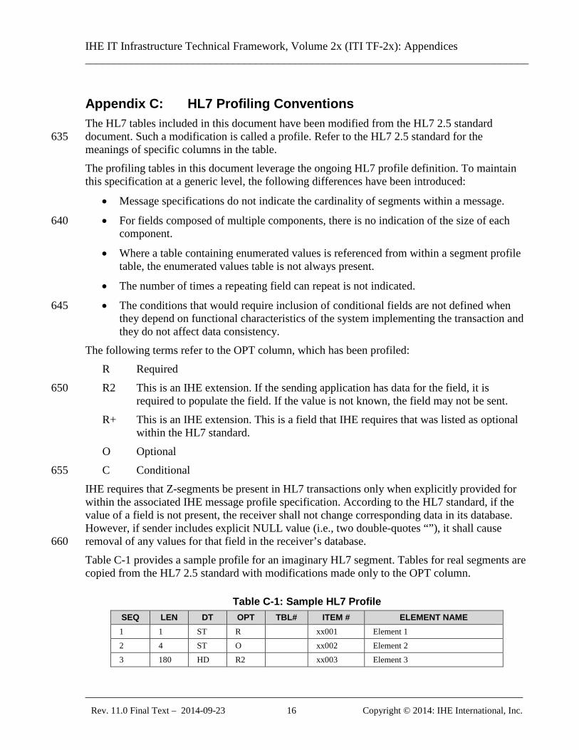
IHE requires that Z-segments be present in HL7 transactions only when explicitly provided for within the associated IHE message profile specification. According to the HL7 standard, if the value of a field is not present, the receiver shall not change corresponding data in its database. However, if sender includes explicit NULL value (i.e., two double-quotes “”), it shall cause removal of any values for that field in the receiver’s database. 660 Table C-1 provides a sample profile for an imaginary HL7 segment. Tables for real segments are copied from the HL7 2.5 standard with modifications made only to the OPT column.
Table C-1: Sample HL7 Profile SEQ LEN DT OPT TBL# ITEM # ELEMENT NAME 1 1 ST R xx001 Element 1 2 4 ST O xx002 Element 2 3 180 HD R2 xx003 Element 3
IHE IT Infrastructure Technical Framework, Volume 2x (ITI TF-2x): Appendices ______________________________________________________________________________
_____________________________________________________________________________ Rev. 11.0 Final Text – 2014-09-23 17 Copyright © 2014: IHE International, Inc.
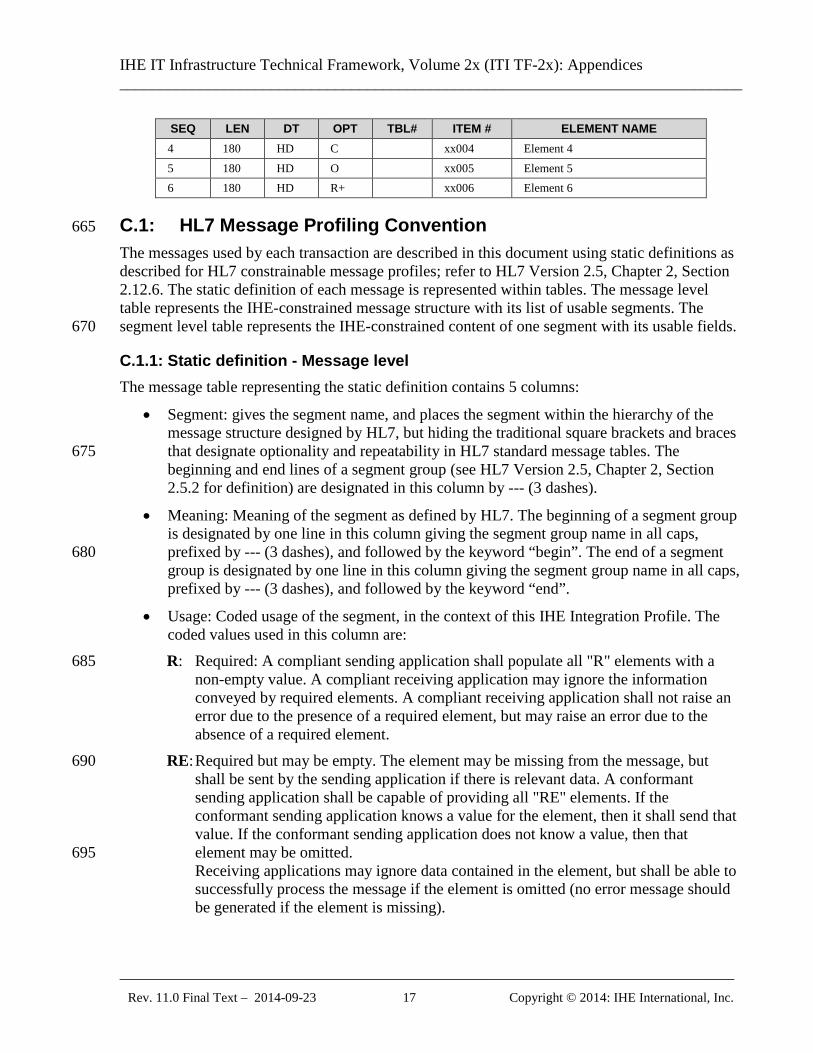
SEQ LEN DT OPT TBL# ITEM # ELEMENT NAME 4 180 HD C xx004 Element 4 5 180 HD O xx005 Element 5 6 180 HD R+ xx006 Element 6
C.1: HL7 Message Profiling Convention 665
The messages used by each transaction are described in this document using static definitions as described for HL7 constrainable message profiles; refer to HL7 Version 2.5, Chapter 2, Section 2.12.6. The static definition of each message is represented within tables. The message level table represents the IHE-constrained message structure with its list of usable segments. The segment level table represents the IHE-constrained content of one segment with its usable fields. 670
C.1.1: Static definition - Message level The message table representing the static definition contains 5 columns:
• Segment: gives the segment name, and places the segment within the hierarchy of the message structure designed by HL7, but hiding the traditional square brackets and braces that designate optionality and repeatability in HL7 standard message tables. The 675 beginning and end lines of a segment group (see HL7 Version 2.5, Chapter 2, Section 2.5.2 for definition) are designated in this column by --- (3 dashes).
• Meaning: Meaning of the segment as defined by HL7. The beginning of a segment group is designated by one line in this column giving the segment group name in all caps, prefixed by --- (3 dashes), and followed by the keyword “begin”. The end of a segment 680 group is designated by one line in this column giving the segment group name in all caps, prefixed by --- (3 dashes), and followed by the keyword “end”.
• Usage: Coded usage of the segment, in the context of this IHE Integration Profile. The coded values used in this column are: R: Required: A compliant sending application shall populate all "R" elements with a 685
non-empty value. A compliant receiving application may ignore the information conveyed by required elements. A compliant receiving application shall not raise an error due to the presence of a required element, but may raise an error due to the absence of a required element.
RE: Required but may be empty. The element may be missing from the message, but 690 shall be sent by the sending application if there is relevant data. A conformant sending application shall be capable of providing all "RE" elements. If the conformant sending application knows a value for the element, then it shall send that value. If the conformant sending application does not know a value, then that element may be omitted. 695 Receiving applications may ignore data contained in the element, but shall be able to successfully process the message if the element is omitted (no error message should be generated if the element is missing).
IHE IT Infrastructure Technical Framework, Volume 2x (ITI TF-2x): Appendices ______________________________________________________________________________
_____________________________________________________________________________ Rev. 11.0 Final Text – 2014-09-23 18 Copyright © 2014: IHE International, Inc.
O: Optional. The usage for this field within the message is not defined . The sending application may choose to populate the field; the receiving application may choose to 700 ignore the field.
C: Conditional. This usage has an associated condition predicate. (See HL7 Version 2.5, Chapter 2, Section 2.12.6.6, "Condition Predicate".) If the predicate is satisfied: A compliant sending application shall populate the element. A compliant receiving application may ignore data in the element. It may 705 raise an error if the element is not present. If the predicate is NOT satisfied: A compliant sending application shall NOT populate the element. A compliant receiving application shall NOT raise an error if the condition predicate is false and the element is not present, though it may raise an error if the element IS present. 710
CE: Conditional but may be empty. This usage has an associated condition predicate. (See HL7 Version 2.5, Chapter 2, Section 2.12.6.6, "Condition Predicate".) If the predicate is satisfied: If the conforming sending application knows the required values for the element, then the application must populate the element. If the conforming sending application does not know the values required for this element, 715 then the element shall be omitted. The conforming sending application must be capable of populating the element (when the predicate is true) for all ‘CE’ elements. If the element is present, the conformant receiving application may ignore the values of that element. If the element is not present, the conformant receiving application shall not raise an error due to the presence or absence of the element. 720 If the predicate is NOT satisfied: The conformant sending application shall not populate the element. The conformant receiving application may raise an application error if the element is present.
X: Not supported. For conformant sending applications, the element will not be sent. Conformant receiving applications may ignore the element if it is sent, or may raise 725 an application error.
• Cardinality: Within square brackets, minimum and maximum number of occurrences authorized for this segment in the context of this Integration Profile.
• HL7 chapter: Reference of the HL7 v2.5 chapter that describes this segment.
C.1.2: Static definition – Segment level and Data Type level 730 The Segment Table and the Data Type Table each contain 8 columns:
• SEQ: Position (sequence) of the field within the segment.
• LEN: Maximum length of the field
• DT: Field Data Type
• Usage: Usage of the field within this IHE Integration Profile. Same coded values as in the 735 message level: R, RE, C, CE, O, X.
IHE IT Infrastructure Technical Framework, Volume 2x (ITI TF-2x): Appendices ______________________________________________________________________________
_____________________________________________________________________________ Rev. 11.0 Final Text – 2014-09-23 19 Copyright © 2014: IHE International, Inc.
• Cardinality: Minimum and maximum number of occurrences for the field in the context of this Integration Profile.
• TBL#: Table reference (for fields using a set of defined values)
• ITEM#: HL7 unique reference for this field 740
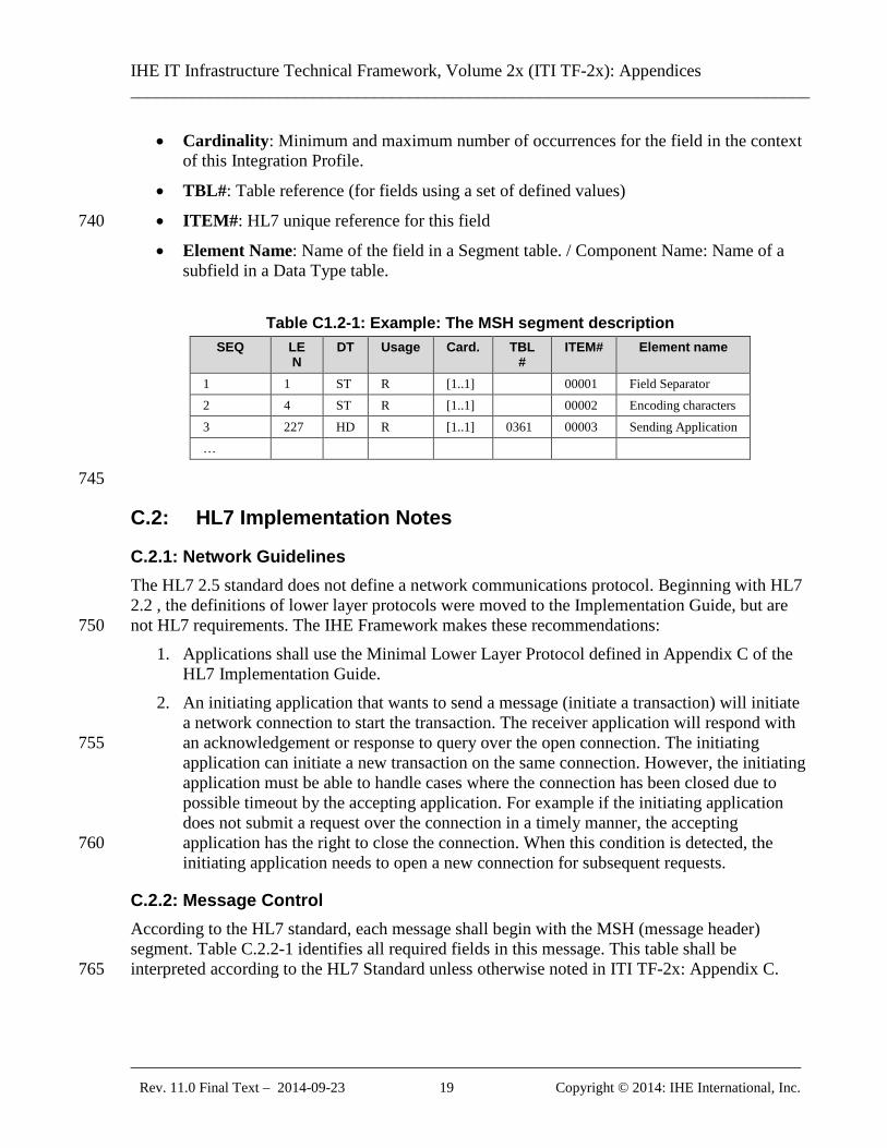
• Element Name: Name of the field in a Segment table. / Component Name: Name of a subfield in a Data Type table.
Table C1.2-1: Example: The MSH segment description
SEQ LEN
DT Usage Card. TBL#
ITEM# Element name
1 1 ST R [1..1] 00001 Field Separator 2 4 ST R [1..1] 00002 Encoding characters 3 227 HD R [1..1] 0361 00003 Sending Application …
745
C.2: HL7 Implementation Notes
C.2.1: Network Guidelines The HL7 2.5 standard does not define a network communications protocol. Beginning with HL7 2.2 , the definitions of lower layer protocols were moved to the Implementation Guide, but are not HL7 requirements. The IHE Framework makes these recommendations: 750
1. Applications shall use the Minimal Lower Layer Protocol defined in Appendix C of the HL7 Implementation Guide.
2. An initiating application that wants to send a message (initiate a transaction) will initiate a network connection to start the transaction. The receiver application will respond with an acknowledgement or response to query over the open connection. The initiating 755 application can initiate a new transaction on the same connection. However, the initiating application must be able to handle cases where the connection has been closed due to possible timeout by the accepting application. For example if the initiating application does not submit a request over the connection in a timely manner, the accepting application has the right to close the connection. When this condition is detected, the 760 initiating application needs to open a new connection for subsequent requests.
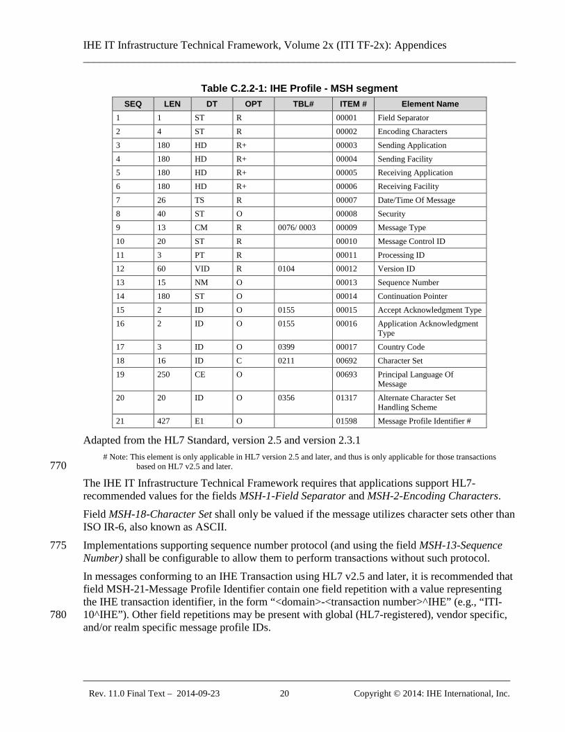
C.2.2: Message Control According to the HL7 standard, each message shall begin with the MSH (message header) segment. Table C.2.2-1 identifies all required fields in this message. This table shall be interpreted according to the HL7 Standard unless otherwise noted in ITI TF-2x: Appendix C. 765
IHE IT Infrastructure Technical Framework, Volume 2x (ITI TF-2x): Appendices ______________________________________________________________________________
_____________________________________________________________________________ Rev. 11.0 Final Text – 2014-09-23 20 Copyright © 2014: IHE International, Inc.
Table C.2.2-1: IHE Profile - MSH segment SEQ LEN DT OPT TBL# ITEM # Element Name
1 1 ST R 00001 Field Separator 2 4 ST R 00002 Encoding Characters 3 180 HD R+ 00003 Sending Application 4 180 HD R+ 00004 Sending Facility 5 180 HD R+ 00005 Receiving Application 6 180 HD R+ 00006 Receiving Facility 7 26 TS R 00007 Date/Time Of Message 8 40 ST O 00008 Security 9 13 CM R 0076/ 0003 00009 Message Type 10 20 ST R 00010 Message Control ID 11 3 PT R 00011 Processing ID 12 60 VID R 0104 00012 Version ID 13 15 NM O 00013 Sequence Number 14 180 ST O 00014 Continuation Pointer 15 2 ID O 0155 00015 Accept Acknowledgment Type 16 2 ID O 0155 00016 Application Acknowledgment
Type 17 3 ID O 0399 00017 Country Code 18 16 ID C 0211 00692 Character Set 19 250 CE O 00693 Principal Language Of
Message 20 20 ID O 0356 01317 Alternate Character Set
Handling Scheme 21 427 E1 O 01598 Message Profile Identifier #
Adapted from the HL7 Standard, version 2.5 and version 2.3.1 # Note: This element is only applicable in HL7 version 2.5 and later, and thus is only applicable for those transactions
based on HL7 v2.5 and later. 770 The IHE IT Infrastructure Technical Framework requires that applications support HL7-recommended values for the fields MSH-1-Field Separator and MSH-2-Encoding Characters. Field MSH-18-Character Set shall only be valued if the message utilizes character sets other than ISO IR-6, also known as ASCII. Implementations supporting sequence number protocol (and using the field MSH-13-Sequence 775 Number) shall be configurable to allow them to perform transactions without such protocol. In messages conforming to an IHE Transaction using HL7 v2.5 and later, it is recommended that field MSH-21-Message Profile Identifier contain one field repetition with a value representing the IHE transaction identifier, in the form “<domain>-<transaction number>^IHE” (e.g., “ITI-10^IHE”). Other field repetitions may be present with global (HL7-registered), vendor specific, 780 and/or realm specific message profile IDs.
IHE IT Infrastructure Technical Framework, Volume 2x (ITI TF-2x): Appendices ______________________________________________________________________________
_____________________________________________________________________________ Rev. 11.0 Final Text – 2014-09-23 21 Copyright © 2014: IHE International, Inc.
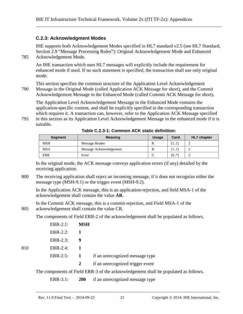
C.2.3: Acknowledgment Modes IHE supports both Acknowledgement Modes specified in HL7 standard v2.5 (see HL7 Standard, Section 2.9 “Message Processing Rules”): Original Acknowledgement Mode and Enhanced Acknowledgement Mode. 785 An IHE transaction which uses HL7 messages will explicitly include the requirement for enhanced mode if used. If no such statement is specified, the transaction shall use only original mode. This section specifies the common structure of the Application Level Acknowledgement Message in the Original Mode (called Application ACK Message for short), and the Commit 790 Acknowledgement Message in the Enhanced Mode (called Commit ACK Message for short). The Application Level Acknowledgement Message in the Enhanced Mode contains the application-specific content, and shall be explicitly specified in the corresponding transaction which requires it. A transaction can, however, refer to the Application ACK Message specified in this section as its Application Level Acknowledgement Message in the enhanced mode if it is 795 suitable.
Table C.2.3-1: Common ACK static definition: Segment Meaning Usage Card. HL7 chapter
MSH Message Header R [1..1] 2 MSA Message Acknowledgement R [1..1] 2 ERR Error C [0..*] 2
In the original mode, the ACK message conveys application errors (if any) detailed by the receiving application. The receiving application shall reject an incoming message, if it does not recognize either the 800 message type (MSH-9.1) or the trigger event (MSH-9.2). In the Application ACK message, this is an application-rejection, and field MSA-1 of the acknowledgement shall contain the value AR. In the Commit ACK message, this is a commit-rejection, and Field MSA-1 of the acknowledgement shall contain the value CR. 805 The components of Field ERR-2 of the acknowledgement shall be populated as follows. ERR-2.1: MSH ERR-2.2: 1 ERR-2.3: 9 ERR-2.4: 1 810 ERR-2.5: 1 if an unrecognized message type 2 if an unrecognized trigger event The components of Field ERR-3 of the acknowledgement shall be populated as follows.
ERR-3.1: 200 if an unrecognized message type
IHE IT Infrastructure Technical Framework, Volume 2x (ITI TF-2x): Appendices ______________________________________________________________________________
_____________________________________________________________________________ Rev. 11.0 Final Text – 2014-09-23 22 Copyright © 2014: IHE International, Inc.
201 if an unrecognized trigger event 815 ERR-3.2: Unsupported message type or Unsupported trigger event as appropriate ERR-3.3: HL70357
Details of field encoding of these segments are discussed in the following sections.
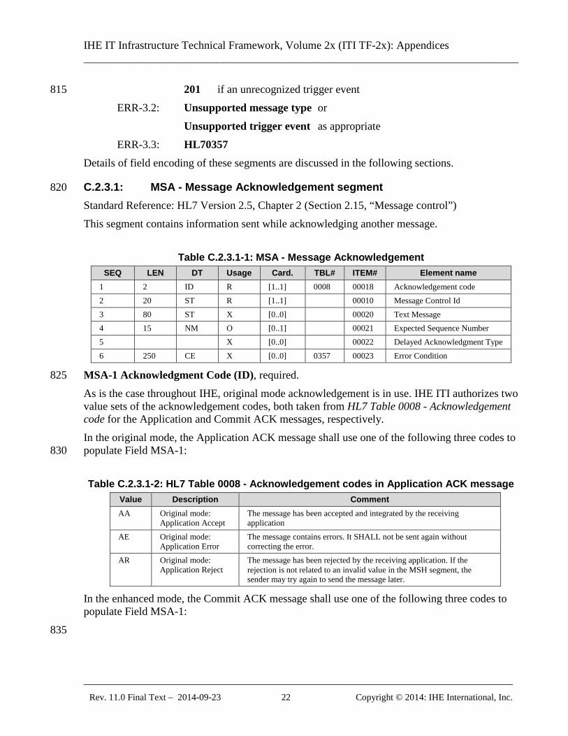
C.2.3.1: MSA - Message Acknowledgement segment 820 Standard Reference: HL7 Version 2.5, Chapter 2 (Section 2.15, “Message control”) This segment contains information sent while acknowledging another message.
Table C.2.3.1-1: MSA - Message Acknowledgement SEQ LEN DT Usage Card. TBL# ITEM# Element name
1 2 ID R [1..1] 0008 00018 Acknowledgement code 2 20 ST R [1..1] 00010 Message Control Id 3 80 ST X [0..0] 00020 Text Message 4 15 NM O [0..1] 00021 Expected Sequence Number 5 X [0..0] 00022 Delayed Acknowledgment Type 6 250 CE X [0..0] 0357 00023 Error Condition
MSA-1 Acknowledgment Code (ID), required. 825 As is the case throughout IHE, original mode acknowledgement is in use. IHE ITI authorizes two value sets of the acknowledgement codes, both taken from HL7 Table 0008 - Acknowledgement code for the Application and Commit ACK messages, respectively. In the original mode, the Application ACK message shall use one of the following three codes to populate Field MSA-1: 830 Table C.2.3.1-2: HL7 Table 0008 - Acknowledgement codes in Application ACK message
Value Description Comment AA Original mode:
Application Accept The message has been accepted and integrated by the receiving application
AE Original mode: Application Error
The message contains errors. It SHALL not be sent again without correcting the error.
AR Original mode: Application Reject
The message has been rejected by the receiving application. If the rejection is not related to an invalid value in the MSH segment, the sender may try again to send the message later.
In the enhanced mode, the Commit ACK message shall use one of the following three codes to populate Field MSA-1: 835
IHE IT Infrastructure Technical Framework, Volume 2x (ITI TF-2x): Appendices ______________________________________________________________________________
_____________________________________________________________________________ Rev. 11.0 Final Text – 2014-09-23 23 Copyright © 2014: IHE International, Inc.
Table C.2.3.1-3: HL7 Table 0008 - Acknowledgement codes in Commit ACK message Value Description Comment CA Enhanced mode:
Commit Accept The message has been received and safe-kept in the receiving application for processing. No resend is required.
CE Enhanced mode: Commit Error
The message contains errors. It SHALL not be sent again without correcting the error.
CR Enhanced mode: Commit Reject
The message has been rejected by the receiving application. If the rejection is not related to an invalid value in the MSH segment, the sender may try again to send the message later.
MSA-2 Message Control ID (ST), required. Definition: This field contains the message control ID from Field MSH-10-Message Control ID 840 of the incoming message for which the acknowledgement is sent. MSA-3 Text Message (ST), not supported. See the ERR segment. MSA-6 Error Condition (CE), not supported. See the ERR segment.
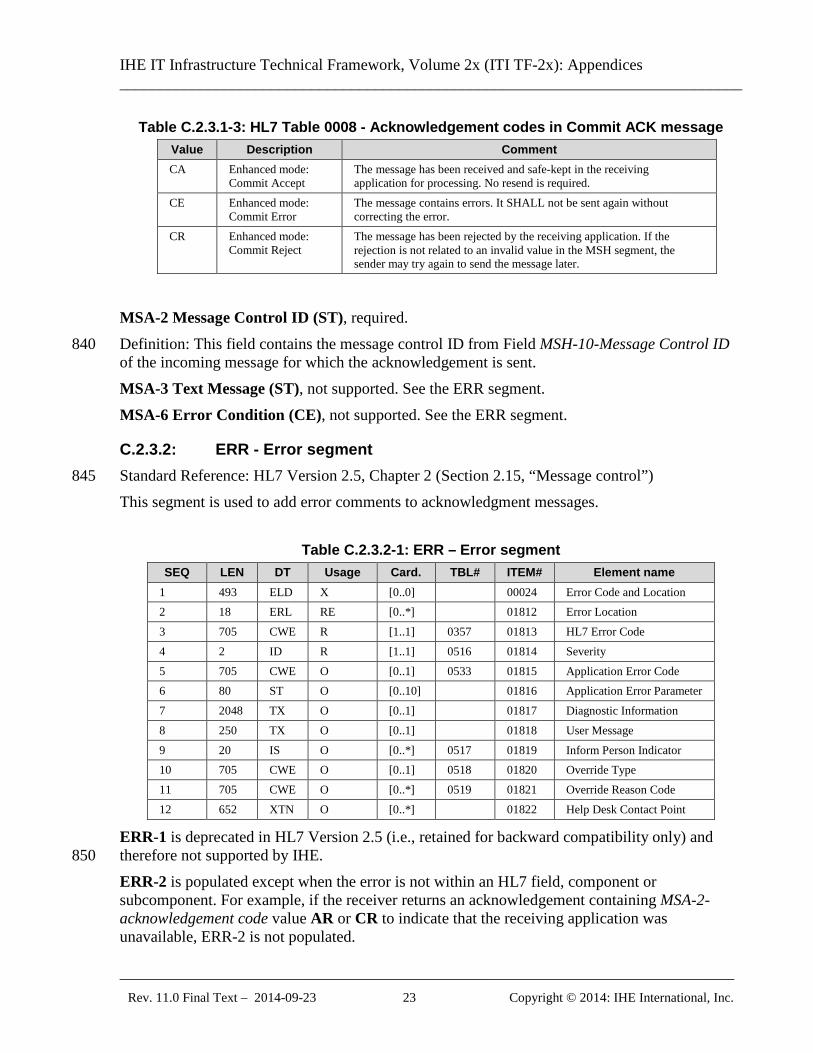
C.2.3.2: ERR - Error segment Standard Reference: HL7 Version 2.5, Chapter 2 (Section 2.15, “Message control”) 845 This segment is used to add error comments to acknowledgment messages.
Table C.2.3.2-1: ERR – Error segment SEQ LEN DT Usage Card. TBL# ITEM# Element name
1 493 ELD X [0..0] 00024 Error Code and Location 2 18 ERL RE [0..*] 01812 Error Location 3 705 CWE R [1..1] 0357 01813 HL7 Error Code 4 2 ID R [1..1] 0516 01814 Severity 5 705 CWE O [0..1] 0533 01815 Application Error Code 6 80 ST O [0..10] 01816 Application Error Parameter 7 2048 TX O [0..1] 01817 Diagnostic Information 8 250 TX O [0..1] 01818 User Message 9 20 IS O [0..*] 0517 01819 Inform Person Indicator 10 705 CWE O [0..1] 0518 01820 Override Type 11 705 CWE O [0..*] 0519 01821 Override Reason Code 12 652 XTN O [0..*] 01822 Help Desk Contact Point
ERR-1 is deprecated in HL7 Version 2.5 (i.e., retained for backward compatibility only) and therefore not supported by IHE. 850 ERR-2 is populated except when the error is not within an HL7 field, component or subcomponent. For example, if the receiver returns an acknowledgement containing MSA-2-acknowledgement code value AR or CR to indicate that the receiving application was unavailable, ERR-2 is not populated.
IHE IT Infrastructure Technical Framework, Volume 2x (ITI TF-2x): Appendices ______________________________________________________________________________
_____________________________________________________________________________ Rev. 11.0 Final Text – 2014-09-23 24 Copyright © 2014: IHE International, Inc.
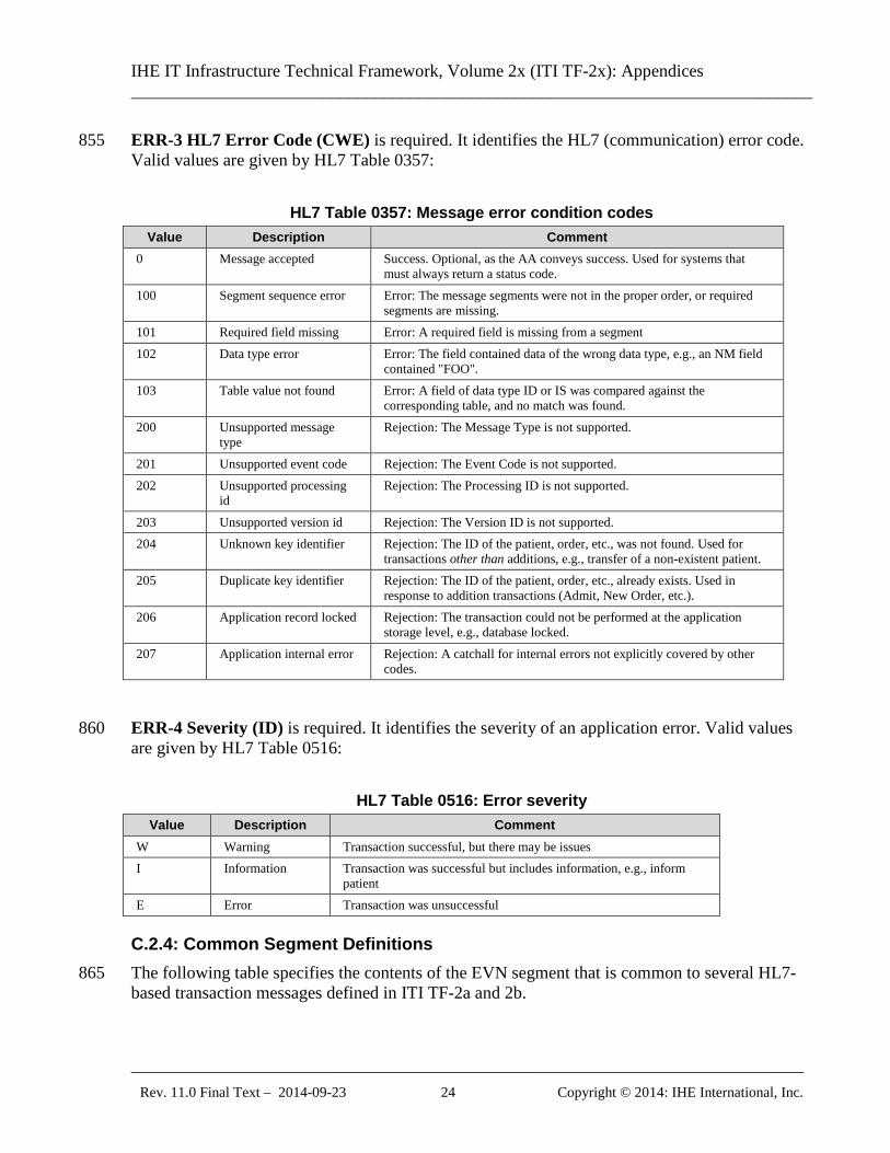
ERR-3 HL7 Error Code (CWE) is required. It identifies the HL7 (communication) error code. 855 Valid values are given by HL7 Table 0357:
HL7 Table 0357: Message error condition codes Value Description Comment
0 Message accepted Success. Optional, as the AA conveys success. Used for systems that must always return a status code.
100 Segment sequence error Error: The message segments were not in the proper order, or required segments are missing.
101 Required field missing Error: A required field is missing from a segment 102 Data type error Error: The field contained data of the wrong data type, e.g., an NM field
contained "FOO". 103 Table value not found Error: A field of data type ID or IS was compared against the
corresponding table, and no match was found. 200 Unsupported message
type Rejection: The Message Type is not supported.
201 Unsupported event code Rejection: The Event Code is not supported. 202 Unsupported processing
id Rejection: The Processing ID is not supported.
203 Unsupported version id Rejection: The Version ID is not supported. 204 Unknown key identifier Rejection: The ID of the patient, order, etc., was not found. Used for
transactions other than additions, e.g., transfer of a non-existent patient. 205 Duplicate key identifier Rejection: The ID of the patient, order, etc., already exists. Used in
response to addition transactions (Admit, New Order, etc.). 206 Application record locked Rejection: The transaction could not be performed at the application
storage level, e.g., database locked. 207 Application internal error Rejection: A catchall for internal errors not explicitly covered by other
codes.
ERR-4 Severity (ID) is required. It identifies the severity of an application error. Valid values 860 are given by HL7 Table 0516:
HL7 Table 0516: Error severity Value Description Comment
W Warning Transaction successful, but there may be issues I Information Transaction was successful but includes information, e.g., inform
patient E Error Transaction was unsuccessful
C.2.4: Common Segment Definitions The following table specifies the contents of the EVN segment that is common to several HL7-865 based transaction messages defined in ITI TF-2a and 2b.
IHE IT Infrastructure Technical Framework, Volume 2x (ITI TF-2x): Appendices ______________________________________________________________________________
_____________________________________________________________________________ Rev. 11.0 Final Text – 2014-09-23 25 Copyright © 2014: IHE International, Inc.
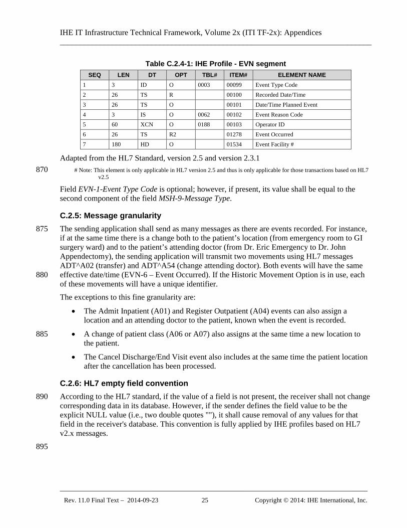
Table C.2.4-1: IHE Profile - EVN segment SEQ LEN DT OPT TBL# ITEM# ELEMENT NAME
1 3 ID O 0003 00099 Event Type Code 2 26 TS R 00100 Recorded Date/Time 3 26 TS O 00101 Date/Time Planned Event 4 3 IS O 0062 00102 Event Reason Code 5 60 XCN O 0188 00103 Operator ID 6 26 TS R2 01278 Event Occurred 7 180 HD O 01534 Event Facility #
Adapted from the HL7 Standard, version 2.5 and version 2.3.1 # Note: This element is only applicable in HL7 version 2.5 and thus is only applicable for those transactions based on HL7 870
v2.5
Field EVN-1-Event Type Code is optional; however, if present, its value shall be equal to the second component of the field MSH-9-Message Type.
C.2.5: Message granularity The sending application shall send as many messages as there are events recorded. For instance, 875 if at the same time there is a change both to the patient’s location (from emergency room to GI surgery ward) and to the patient’s attending doctor (from Dr. Eric Emergency to Dr. John Appendectomy), the sending application will transmit two movements using HL7 messages ADT^A02 (transfer) and ADT^A54 (change attending doctor). Both events will have the same effective date/time (EVN-6 – Event Occurred). If the Historic Movement Option is in use, each 880 of these movements will have a unique identifier. The exceptions to this fine granularity are:
• The Admit Inpatient (A01) and Register Outpatient (A04) events can also assign a location and an attending doctor to the patient, known when the event is recorded.
• A change of patient class (A06 or A07) also assigns at the same time a new location to 885 the patient.
• The Cancel Discharge/End Visit event also includes at the same time the patient location after the cancellation has been processed.
C.2.6: HL7 empty field convention According to the HL7 standard, if the value of a field is not present, the receiver shall not change 890 corresponding data in its database. However, if the sender defines the field value to be the explicit NULL value (i.e., two double quotes ""), it shall cause removal of any values for that field in the receiver's database. This convention is fully applied by IHE profiles based on HL7 v2.x messages. 895
IHE IT Infrastructure Technical Framework, Volume 2x (ITI TF-2x): Appendices ______________________________________________________________________________
_____________________________________________________________________________ Rev. 11.0 Final Text – 2014-09-23 26 Copyright © 2014: IHE International, Inc.
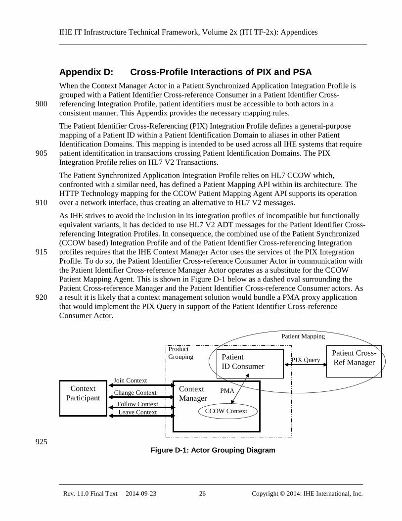
Appendix D: Cross-Profile Interactions of PIX and PSA When the Context Manager Actor in a Patient Synchronized Application Integration Profile is grouped with a Patient Identifier Cross-reference Consumer in a Patient Identifier Cross-referencing Integration Profile, patient identifiers must be accessible to both actors in a 900 consistent manner. This Appendix provides the necessary mapping rules. The Patient Identifier Cross-Referencing (PIX) Integration Profile defines a general-purpose mapping of a Patient ID within a Patient Identification Domain to aliases in other Patient Identification Domains. This mapping is intended to be used across all IHE systems that require patient identification in transactions crossing Patient Identification Domains. The PIX 905 Integration Profile relies on HL7 V2 Transactions. The Patient Synchronized Application Integration Profile relies on HL7 CCOW which, confronted with a similar need, has defined a Patient Mapping API within its architecture. The HTTP Technology mapping for the CCOW Patient Mapping Agent API supports its operation over a network interface, thus creating an alternative to HL7 V2 messages. 910 As IHE strives to avoid the inclusion in its integration profiles of incompatible but functionally equivalent variants, it has decided to use HL7 V2 ADT messages for the Patient Identifier Cross-referencing Integration Profiles. In consequence, the combined use of the Patient Synchronized (CCOW based) Integration Profile and of the Patient Identifier Cross-referencing Integration profiles requires that the IHE Context Manager Actor uses the services of the PIX Integration 915 Profile. To do so, the Patient Identifier Cross-reference Consumer Actor in communication with the Patient Identifier Cross-reference Manager Actor operates as a substitute for the CCOW Patient Mapping Agent. This is shown in Figure D-1 below as a dashed oval surrounding the Patient Cross-reference Manager and the Patient Identifier Cross-reference Consumer actors. As a result it is likely that a context management solution would bundle a PMA proxy application 920 that would implement the PIX Query in support of the Patient Identifier Cross-reference Consumer Actor.
Patient ID Consumer
Context Participant
Context Manager
Join Context
Change Context
Leave Context
Patient Cross-Ref Manager
Patient Mapping
CCOW Context
PMA
PIX Query
Product Grouping
Follow Context
925 Figure D-1: Actor Grouping Diagram
IHE IT Infrastructure Technical Framework, Volume 2x (ITI TF-2x): Appendices ______________________________________________________________________________
_____________________________________________________________________________ Rev. 11.0 Final Text – 2014-09-23 27 Copyright © 2014: IHE International, Inc.
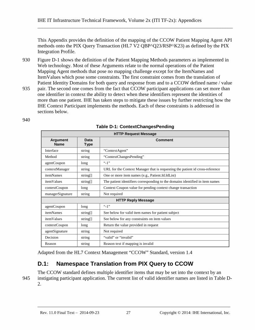
This Appendix provides the definition of the mapping of the CCOW Patient Mapping Agent API methods onto the PIX Query Transaction (HL7 V2 QBP^Q23/RSP^K23) as defined by the PIX Integration Profile. Figure D-1 shows the definition of the Patient Mapping Methods parameters as implemented in 930 Web technology. Most of these Arguments relate to the normal operations of the Patient Mapping Agent methods that pose no mapping challenge except for the ItemNames and ItemValues which pose some constraints. The first constraint comes from the translation of Patient Identity Domains for both query and response from and to a CCOW defined name / value pair. The second one comes from the fact that CCOW participant applications can set more than 935 one identifier in context the ability to detect when these identifiers represent the identities of more than one patient. IHE has taken steps to mitigate these issues by further restricting how the IHE Context Participant implements the methods. Each of these constraints is addressed in sections below. 940
Table D-1: ContextChangesPending HTTP Request Message
Argument Name
Data Type
Comment
Interface string “ContextAgent” Method string “ContextChangesPending” agentCoupon long “-1” contextManager string URL for the Context Manager that is requesting the patient id cross-reference itemNames string[] One or more item names (e.g., Patient.Id.IdList) itemValues string[] The patient identifiers corresponding to the domains identified in item names contextCoupon long Context Coupon value for pending context change transaction managerSignature string Not required
HTTP Reply Message agentCoupon long “-1” itemNames string[] See below for valid item names for patient subject itemValues string[] See below for any constraints on item values contextCoupon long Return the value provided in request agentSignature string Not required Decision string “valid” or “invalid” Reason string Reason text if mapping is invalid
Adapted from the HL7 Context Management “CCOW” Standard, version 1.4
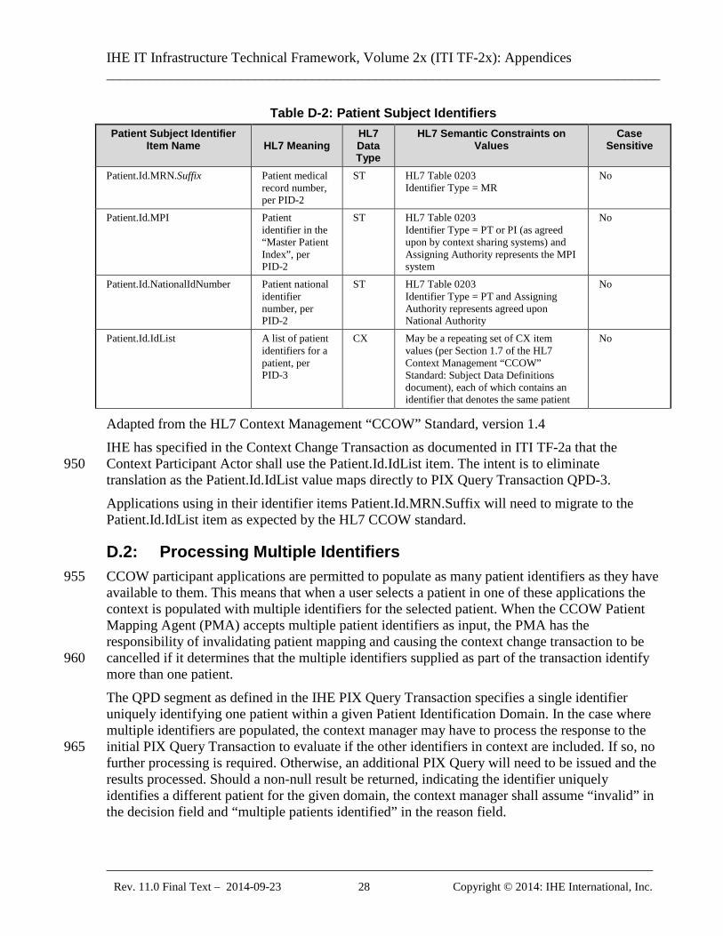
D.1: Namespace Translation from PIX Query to CCOW The CCOW standard defines multiple identifier items that may be set into the context by an instigating participant application. The current list of valid identifier names are listed in Table D-945 2.
IHE IT Infrastructure Technical Framework, Volume 2x (ITI TF-2x): Appendices ______________________________________________________________________________
_____________________________________________________________________________ Rev. 11.0 Final Text – 2014-09-23 28 Copyright © 2014: IHE International, Inc.
Table D-2: Patient Subject Identifiers Patient Subject Identifier
Item Name
HL7 Meaning HL7 Data Type
HL7 Semantic Constraints on Values
Case Sensitive
Patient.Id.MRN.Suffix Patient medical record number, per PID-2
ST HL7 Table 0203 Identifier Type = MR
No
Patient.Id.MPI Patient identifier in the “Master Patient Index”, per PID-2
ST HL7 Table 0203 Identifier Type = PT or PI (as agreed upon by context sharing systems) and Assigning Authority represents the MPI system
No
Patient.Id.NationalIdNumber Patient national identifier number, per PID-2
ST HL7 Table 0203 Identifier Type = PT and Assigning Authority represents agreed upon National Authority
No
Patient.Id.IdList A list of patient identifiers for a patient, per PID-3
CX May be a repeating set of CX item values (per Section 1.7 of the HL7 Context Management “CCOW” Standard: Subject Data Definitions document), each of which contains an identifier that denotes the same patient
No
Adapted from the HL7 Context Management “CCOW” Standard, version 1.4 IHE has specified in the Context Change Transaction as documented in ITI TF-2a that the Context Participant Actor shall use the Patient.Id.IdList item. The intent is to eliminate 950 translation as the Patient.Id.IdList value maps directly to PIX Query Transaction QPD-3. Applications using in their identifier items Patient.Id.MRN.Suffix will need to migrate to the Patient.Id.IdList item as expected by the HL7 CCOW standard.
D.2: Processing Multiple Identifiers CCOW participant applications are permitted to populate as many patient identifiers as they have 955 available to them. This means that when a user selects a patient in one of these applications the context is populated with multiple identifiers for the selected patient. When the CCOW Patient Mapping Agent (PMA) accepts multiple patient identifiers as input, the PMA has the responsibility of invalidating patient mapping and causing the context change transaction to be cancelled if it determines that the multiple identifiers supplied as part of the transaction identify 960 more than one patient. The QPD segment as defined in the IHE PIX Query Transaction specifies a single identifier uniquely identifying one patient within a given Patient Identification Domain. In the case where multiple identifiers are populated, the context manager may have to process the response to the initial PIX Query Transaction to evaluate if the other identifiers in context are included. If so, no 965 further processing is required. Otherwise, an additional PIX Query will need to be issued and the results processed. Should a non-null result be returned, indicating the identifier uniquely identifies a different patient for the given domain, the context manager shall assume “invalid” in the decision field and “multiple patients identified” in the reason field.
IHE IT Infrastructure Technical Framework, Volume 2x (ITI TF-2x): Appendices ______________________________________________________________________________
_____________________________________________________________________________ Rev. 11.0 Final Text – 2014-09-23 29 Copyright © 2014: IHE International, Inc.
In order to mitigate this condition, IHE specifies that all context participants supporting the 970 Patient Synchronized Applications Profile shall only set one identifier for the patient when a Patient Identifier Cross-referencing Integration Profile is used by the context manager. This means that the context participant for those applications that manage multiple patient identifiers will need to be configurable as to which identifier item is passed in the Change Context Transaction. 975
IHE IT Infrastructure Technical Framework, Volume 2x (ITI TF-2x): Appendices ______________________________________________________________________________
_____________________________________________________________________________ Rev. 11.0 Final Text – 2014-09-23 30 Copyright © 2014: IHE International, Inc.
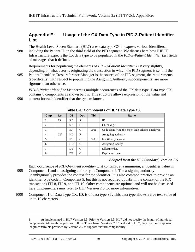
Appendix E: Usage of the CX Data Type in PID-3-Patient Identifier List The Health Level Seven Standard (HL7) uses data type CX to express various identifiers, including the Patient ID in the third field of the PID segment. We discuss here how IHE IT 980 Infrastructure expects the CX data type to be populated in the PID-3-Patient Identifier List fields of messages that it defines. Requirements for populating the elements of PID-3-Patient Identifier List vary slightly, depending on what actor is originating the transaction in which the PID segment is sent. If the Patient Identifier Cross-reference Manager is the source of the PID segment, the requirements 985 (specifically, with respect to populating the Assigning Authority subcomponents) are more rigorous than otherwise. PID-3-Patient Identifier List permits multiple occurrences of the CX data type. Data type CX contains 8 components as shown below. This structure allows expression of the value and context for each identifier that the system knows. 990
Table E-1: Components of HL7 Data Type CX Cmp Len DT Opt Tbl Name 1 15 ST R ID 2 ST O Check digit 3 ID O 0061 Code identifying the check digit scheme employed 4 227 HD R Assigning authority 5 ID O 0203 Identifier type code 6 HD O Assigning facility 7 DT O Effective date 8 DT O Expiration date
Adapted from the HL7 Standard, Version 2.5 Each occurrence of PID-3-Patient Identifier List contains, at a minimum, an identifier value in Component 1 and an assigning authority in Component 4. The assigning authority 995 unambiguously provides the context for the identifier. It is also common practice to provide an identifier type code in Component 5, but this is not required by IHE in the context of the PIX transactions ITI-8, ITI-9, and ITI-10. Other components are optional and will not be discussed here; implementers may refer to HL7 Version 2.5 for more information. Component 1 of Data Type CX, ID, is of data type ST. This data type allows a free text value of 1000 up to 15 characters.1
1 As implemented in HL7 Version 2.5. Prior to Version 2.5, HL7 did not specify the length of individual components. Although the profiles in IHE-ITI are based Versions 2.3.1 and 2.4 of HL7, they use the component length constraints provided by Version 2.5 to support forward compatibility.
IHE IT Infrastructure Technical Framework, Volume 2x (ITI TF-2x): Appendices ______________________________________________________________________________
_____________________________________________________________________________ Rev. 11.0 Final Text – 2014-09-23 31 Copyright © 2014: IHE International, Inc.
Component 4 of Data Type CX, Assigning Authority, is of data type HD. This data type contains 3 components that, when implemented at the component level, become subcomponents of Component 4. The requirements for the subcomponents of Component 4 vary by actor.
E.1: Patient Identifier Cross-reference Manager Actor Requirements 1005
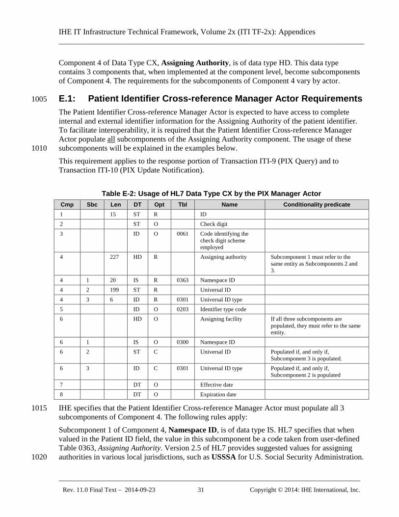
The Patient Identifier Cross-reference Manager Actor is expected to have access to complete internal and external identifier information for the Assigning Authority of the patient identifier. To facilitate interoperability, it is required that the Patient Identifier Cross-reference Manager Actor populate all subcomponents of the Assigning Authority component. The usage of these subcomponents will be explained in the examples below. 1010 This requirement applies to the response portion of Transaction ITI-9 (PIX Query) and to Transaction ITI-10 (PIX Update Notification).
Table E-2: Usage of HL7 Data Type CX by the PIX Manager Actor Cmp Sbc Len DT Opt Tbl Name Conditionality predicate 1 15 ST R ID 2 ST O Check digit 3 ID O 0061 Code identifying the
check digit scheme employed
4 227 HD R Assigning authority Subcomponent 1 must refer to the same entity as Subcomponents 2 and 3.
4 1 20 IS R 0363 Namespace ID 4 2 199 ST R Universal ID 4 3 6 ID R 0301 Universal ID type 5 ID O 0203 Identifier type code 6 HD O Assigning facility If all three subcomponents are
populated, they must refer to the same entity.
6 1 IS O 0300 Namespace ID 6 2 ST C Universal ID Populated if, and only if,
Subcomponent 3 is populated. 6 3 ID C 0301 Universal ID type Populated if, and only if,
Subcomponent 2 is populated 7 DT O Effective date 8 DT O Expiration date
IHE specifies that the Patient Identifier Cross-reference Manager Actor must populate all 3 1015 subcomponents of Component 4. The following rules apply: Subcomponent 1 of Component 4, Namespace ID, is of data type IS. HL7 specifies that when valued in the Patient ID field, the value in this subcomponent be a code taken from user-defined Table 0363, Assigning Authority. Version 2.5 of HL7 provides suggested values for assigning authorities in various local jurisdictions, such as USSSA for U.S. Social Security Administration. 1020
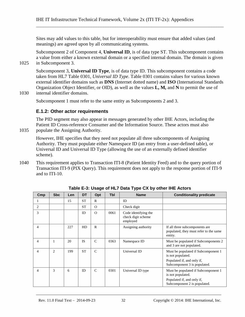
IHE IT Infrastructure Technical Framework, Volume 2x (ITI TF-2x): Appendices ______________________________________________________________________________
_____________________________________________________________________________ Rev. 11.0 Final Text – 2014-09-23 32 Copyright © 2014: IHE International, Inc.
Sites may add values to this table, but for interoperability must ensure that added values (and meanings) are agreed upon by all communicating systems. Subcomponent 2 of Component 4, Universal ID, is of data type ST. This subcomponent contains a value from either a known external domain or a specified internal domain. The domain is given in Subcomponent 3. 1025 Subcomponent 3, Universal ID Type, is of data type ID. This subcomponent contains a code taken from HL7 Table 0301, Universal ID Type. Table 0301 contains values for various known external identifier domains such as DNS (Internet dotted name) and ISO (International Standards Organization Object Identifier, or OID), as well as the values L, M, and N to permit the use of internal identifier domains. 1030 Subcomponent 1 must refer to the same entity as Subcomponents 2 and 3.
E.1.2: Other actor requirements The PID segment may also appear in messages generated by other IHE Actors, including the Patient ID Cross-reference Consumer and the Information Source. These actors must also populate the Assigning Authority. 1035 However, IHE specifies that they need not populate all three subcomponents of Assigning Authority. They must populate either Namespace ID (an entry from a user-defined table), or Universal ID and Universal ID Type (allowing the use of an externally defined identifier scheme). This requirement applies to Transaction ITI-8 (Patient Identity Feed) and to the query portion of 1040 Transaction ITI-9 (PIX Query). This requirement does not apply to the response portion of ITI-9 and to ITI-10.
Table E-3: Usage of HL7 Data Type CX by other IHE Actors Cmp Sbc Len DT Opt Tbl Name Conditionality predicate 1 15 ST R ID 2 ST O Check digit 3 ID O 0061 Code identifying the
check digit scheme employed
4 227 HD R Assigning authority If all three subcomponents are populated, they must refer to the same entity.
4 1 20 IS C 0363 Namespace ID Must be populated if Subcomponents 2 and 3 are not populated.
4 2 199 ST C Universal ID Must be populated if Subcomponent 1 is not populated. Populated if, and only if, Subcomponent 3 is populated.
4 3 6 ID C 0301 Universal ID type Must be populated if Subcomponent 1 is not populated. Populated if, and only if, Subcomponent 2 is populated.
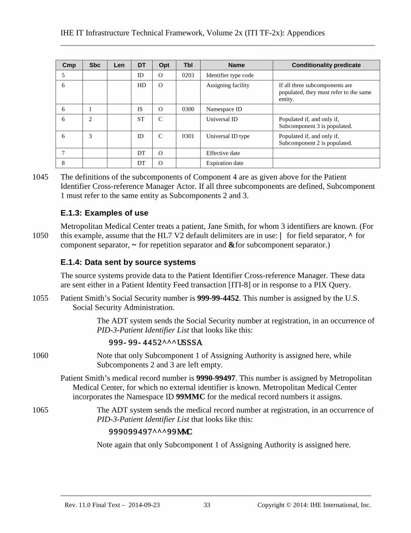
IHE IT Infrastructure Technical Framework, Volume 2x (ITI TF-2x): Appendices ______________________________________________________________________________
_____________________________________________________________________________ Rev. 11.0 Final Text – 2014-09-23 33 Copyright © 2014: IHE International, Inc.
Cmp Sbc Len DT Opt Tbl Name Conditionality predicate 5 ID O 0203 Identifier type code 6 HD O Assigning facility If all three subcomponents are
populated, they must refer to the same entity.
6 1 IS O 0300 Namespace ID 6 2 ST C Universal ID Populated if, and only if,
Subcomponent 3 is populated. 6 3 ID C 0301 Universal ID type Populated if, and only if,
Subcomponent 2 is populated.
7 DT O Effective date 8 DT O Expiration date
The definitions of the subcomponents of Component 4 are as given above for the Patient 1045 Identifier Cross-reference Manager Actor. If all three subcomponents are defined, Subcomponent 1 must refer to the same entity as Subcomponents 2 and 3.
E.1.3: Examples of use Metropolitan Medical Center treats a patient, Jane Smith, for whom 3 identifiers are known. (For this example, assume that the HL7 V2 default delimiters are in use: | for field separator, ^ for 1050 component separator, ~ for repetition separator and & for subcomponent separator.)
E.1.4: Data sent by source systems The source systems provide data to the Patient Identifier Cross-reference Manager. These data are sent either in a Patient Identity Feed transaction [ITI-8] or in response to a PIX Query. Patient Smith’s Social Security number is 999-99-4452. This number is assigned by the U.S. 1055
Social Security Administration. The ADT system sends the Social Security number at registration, in an occurrence of PID-3-Patient Identifier List that looks like this:
999-99-4452^^^USSSA
Note that only Subcomponent 1 of Assigning Authority is assigned here, while 1060 Subcomponents 2 and 3 are left empty.
Patient Smith’s medical record number is 9990-99497. This number is assigned by Metropolitan Medical Center, for which no external identifier is known. Metropolitan Medical Center incorporates the Namespace ID 99MMC for the medical record numbers it assigns.
The ADT system sends the medical record number at registration, in an occurrence of 1065 PID-3-Patient Identifier List that looks like this:
999099497^^^99MMC
Note again that only Subcomponent 1 of Assigning Authority is assigned here.
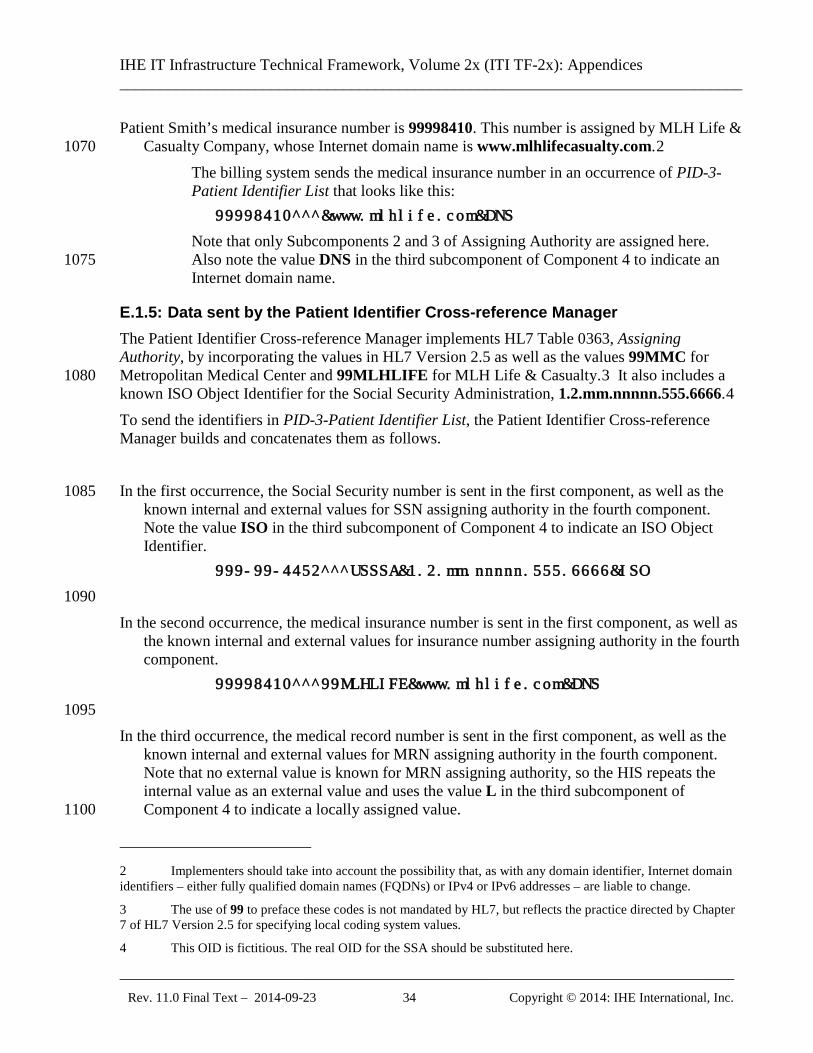
IHE IT Infrastructure Technical Framework, Volume 2x (ITI TF-2x): Appendices ______________________________________________________________________________
_____________________________________________________________________________ Rev. 11.0 Final Text – 2014-09-23 34 Copyright © 2014: IHE International, Inc.
Patient Smith’s medical insurance number is 99998410. This number is assigned by MLH Life & Casualty Company, whose Internet domain name is www.mlhlifecasualty.com.2 1070
The billing system sends the medical insurance number in an occurrence of PID-3-Patient Identifier List that looks like this:
99998410^^^&www.mlhlife.com&DNS
Note that only Subcomponents 2 and 3 of Assigning Authority are assigned here. Also note the value DNS in the third subcomponent of Component 4 to indicate an 1075 Internet domain name.
E.1.5: Data sent by the Patient Identifier Cross-reference Manager The Patient Identifier Cross-reference Manager implements HL7 Table 0363, Assigning Authority, by incorporating the values in HL7 Version 2.5 as well as the values 99MMC for Metropolitan Medical Center and 99MLHLIFE for MLH Life & Casualty.3 It also includes a 1080 known ISO Object Identifier for the Social Security Administration, 1.2.mm.nnnnn.555.6666.4 To send the identifiers in PID-3-Patient Identifier List, the Patient Identifier Cross-reference Manager builds and concatenates them as follows. In the first occurrence, the Social Security number is sent in the first component, as well as the 1085
known internal and external values for SSN assigning authority in the fourth component. Note the value ISO in the third subcomponent of Component 4 to indicate an ISO Object Identifier.
999-99-4452^^^USSSA&1.2.mm.nnnnn.555.6666&ISO
1090 In the second occurrence, the medical insurance number is sent in the first component, as well as
the known internal and external values for insurance number assigning authority in the fourth component.
99998410^^^99MLHLIFE&www.mlhlife.com&DNS
1095 In the third occurrence, the medical record number is sent in the first component, as well as the
known internal and external values for MRN assigning authority in the fourth component. Note that no external value is known for MRN assigning authority, so the HIS repeats the internal value as an external value and uses the value L in the third subcomponent of Component 4 to indicate a locally assigned value. 1100
2 Implementers should take into account the possibility that, as with any domain identifier, Internet domain identifiers – either fully qualified domain names (FQDNs) or IPv4 or IPv6 addresses – are liable to change.
3 The use of 99 to preface these codes is not mandated by HL7, but reflects the practice directed by Chapter 7 of HL7 Version 2.5 for specifying local coding system values.
4 This OID is fictitious. The real OID for the SSA should be substituted here.
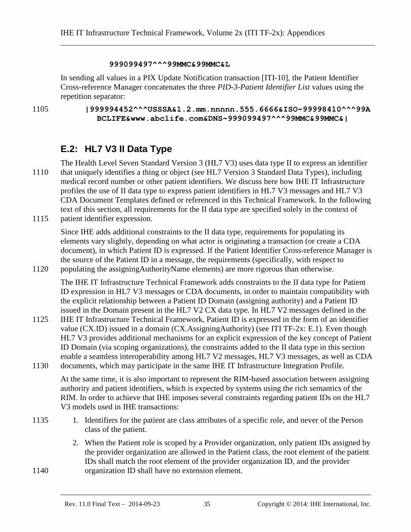
IHE IT Infrastructure Technical Framework, Volume 2x (ITI TF-2x): Appendices ______________________________________________________________________________
_____________________________________________________________________________ Rev. 11.0 Final Text – 2014-09-23 35 Copyright © 2014: IHE International, Inc.
999099497^^^99MMC&99MMC&L
In sending all values in a PIX Update Notification transaction [ITI-10], the Patient Identifier Cross-reference Manager concatenates the three PID-3-Patient Identifier List values using the repetition separator:
|999994452^^^USSSA&1.2.mm.nnnnn.555.6666&ISO~99998410^^^99A1105 BCLIFE&www.abclife.com&DNS~999099497^^^99MMC&99MMC&|
E.2: HL7 V3 II Data Type The Health Level Seven Standard Version 3 (HL7 V3) uses data type II to express an identifier that uniquely identifies a thing or object (see HL7 Version 3 Standard Data Types), including 1110 medical record number or other patient identifiers. We discuss here how IHE IT Infrastructure profiles the use of II data type to express patient identifiers in HL7 V3 messages and HL7 V3 CDA Document Templates defined or referenced in this Technical Framework. In the following text of this section, all requirements for the II data type are specified solely in the context of patient identifier expression. 1115 Since IHE adds additional constraints to the II data type, requirements for populating its elements vary slightly, depending on what actor is originating a transaction (or create a CDA document), in which Patient ID is expressed. If the Patient Identifier Cross-reference Manager is the source of the Patient ID in a message, the requirements (specifically, with respect to populating the assigningAuthorityName elements) are more rigorous than otherwise. 1120 The IHE IT Infrastructure Technical Framework adds constraints to the II data type for Patient ID expression in HL7 V3 messages or CDA documents, in order to maintain compatibility with the explicit relationship between a Patient ID Domain (assigning authority) and a Patient ID issued in the Domain present in the HL7 V2 CX data type. In HL7 V2 messages defined in the IHE IT Infrastructure Technical Framework, Patient ID is expressed in the form of an identifier 1125 value (CX.ID) issued in a domain (CX.AssigningAuthority) (see ITI TF-2x: E.1). Even though HL7 V3 provides additional mechanisms for an explicit expression of the key concept of Patient ID Domain (via scoping organizations), the constraints added to the II data type in this section enable a seamless interoperability among HL7 V2 messages, HL7 V3 messages, as well as CDA documents, which may participate in the same IHE IT Infrastructure Integration Profile. 1130 At the same time, it is also important to represent the RIM-based association between assigning authority and patient identifiers, which is expected by systems using the rich semantics of the RIM. In order to achieve that IHE imposes several constraints regarding patient IDs on the HL7 V3 models used in IHE transactions:
1. Identifiers for the patient are class attributes of a specific role, and never of the Person 1135 class of the patient.
2. When the Patient role is scoped by a Provider organization, only patient IDs assigned by the provider organization are allowed in the Patient class, the root element of the patient IDs shall match the root element of the provider organization ID, and the provider organization ID shall have no extension element. 1140
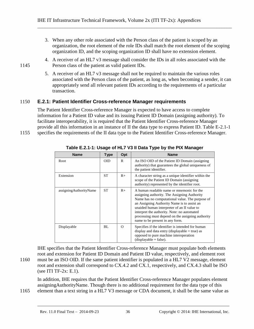
IHE IT Infrastructure Technical Framework, Volume 2x (ITI TF-2x): Appendices ______________________________________________________________________________
_____________________________________________________________________________ Rev. 11.0 Final Text – 2014-09-23 36 Copyright © 2014: IHE International, Inc.
3. When any other role associated with the Person class of the patient is scoped by an organization, the root element of the role IDs shall match the root element of the scoping organization ID, and the scoping organization ID shall have no extension element.
4. A receiver of an HL7 v3 message shall consider the IDs in all roles associated with the Person class of the patient as valid patient IDs. 1145
5. A receiver of an HL7 v3 message shall not be required to maintain the various roles associated with the Person class of the patient, as long as, when becoming a sender, it can appropriately send all relevant patient IDs according to the requirements of a particular transaction.
E.2.1: Patient Identifier Cross-reference Manager requirements 1150 The Patient Identifier Cross-reference Manager is expected to have access to complete information for a Patient ID value and its issuing Patient ID Domain (assigning authority). To facilitate interoperability, it is required that the Patient Identifier Cross-reference Manager provide all this information in an instance of II the data type to express Patient ID. Table E-2.1-1 specifies the requirements of the II data type to the Patient Identifier Cross-reference Manager. 1155
Table E.2.1-1: Usage of HL7 V3 II Data Type by the PIX Manager Name Type Opt Name
Root OID R An ISO OID of the Patient ID Domain (assigning authority) that guarantees the global uniqueness of the patient identifier.
Extension ST R+ A character string as a unique identifier within the scope of the Patient ID Domain (assigning authority) represented by the identifier root.
assigningAuthorityName ST R+ A human readable name or mnemonic for the assigning authority. The Assigning Authority Name has no computational value. The purpose of an Assigning Authority Name is to assist an unaided human interpreter of an II value to interpret the authority. Note: no automated processing must depend on the assigning authority name to be present in any form.
Displayable BL O Specifies if the identifier is intended for human display and data entry (displayable = true) as opposed to pure machine interoperation (displayable = false).
IHE specifies that the Patient Identifier Cross-reference Manager must populate both elements root and extension for Patient ID Domain and Patient ID value, respectively, and element root must be an ISO OID. If the same patient identifier is populated in a HL7 V2 message, element 1160 root and extension shall correspond to CX.4.2 and CX.1, respectively, and CX.4.3 shall be ISO (see ITI TF-2x: E.1). In addition, IHE requires that the Patient Identifier Cross-reference Manager populates element assigningAuthorityName. Though there is no additional requirement for the data type of this element than a text string in a HL7 V3 message or CDA document, it shall be the same value as 1165
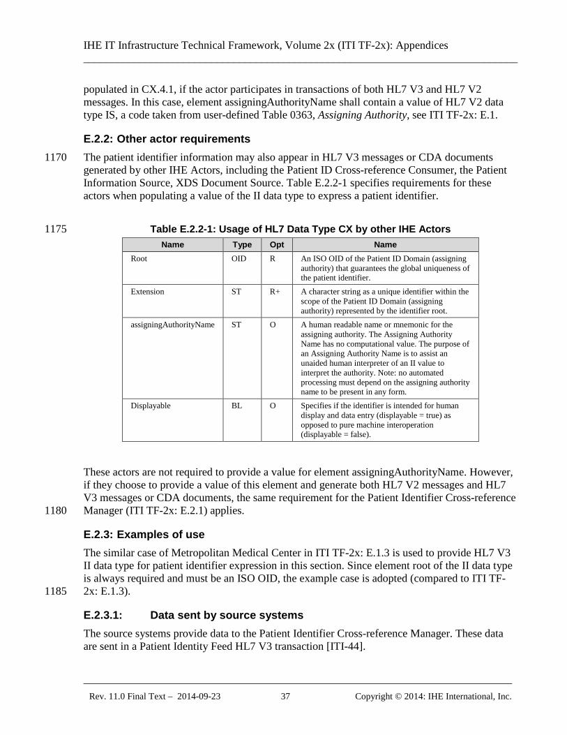
IHE IT Infrastructure Technical Framework, Volume 2x (ITI TF-2x): Appendices ______________________________________________________________________________
_____________________________________________________________________________ Rev. 11.0 Final Text – 2014-09-23 37 Copyright © 2014: IHE International, Inc.
populated in CX.4.1, if the actor participates in transactions of both HL7 V3 and HL7 V2 messages. In this case, element assigningAuthorityName shall contain a value of HL7 V2 data type IS, a code taken from user-defined Table 0363, Assigning Authority, see ITI TF-2x: E.1.
E.2.2: Other actor requirements The patient identifier information may also appear in HL7 V3 messages or CDA documents 1170 generated by other IHE Actors, including the Patient ID Cross-reference Consumer, the Patient Information Source, XDS Document Source. Table E.2.2-1 specifies requirements for these actors when populating a value of the II data type to express a patient identifier.
Table E.2.2-1: Usage of HL7 Data Type CX by other IHE Actors 1175 Name Type Opt Name
Root OID R An ISO OID of the Patient ID Domain (assigning authority) that guarantees the global uniqueness of the patient identifier.
Extension ST R+ A character string as a unique identifier within the scope of the Patient ID Domain (assigning authority) represented by the identifier root.
assigningAuthorityName ST O A human readable name or mnemonic for the assigning authority. The Assigning Authority Name has no computational value. The purpose of an Assigning Authority Name is to assist an unaided human interpreter of an II value to interpret the authority. Note: no automated processing must depend on the assigning authority name to be present in any form.
Displayable BL O Specifies if the identifier is intended for human display and data entry (displayable = true) as opposed to pure machine interoperation (displayable = false).
These actors are not required to provide a value for element assigningAuthorityName. However, if they choose to provide a value of this element and generate both HL7 V2 messages and HL7 V3 messages or CDA documents, the same requirement for the Patient Identifier Cross-reference Manager (ITI TF-2x: E.2.1) applies. 1180
E.2.3: Examples of use The similar case of Metropolitan Medical Center in ITI TF-2x: E.1.3 is used to provide HL7 V3 II data type for patient identifier expression in this section. Since element root of the II data type is always required and must be an ISO OID, the example case is adopted (compared to ITI TF-2x: E.1.3). 1185
E.2.3.1: Data sent by source systems The source systems provide data to the Patient Identifier Cross-reference Manager. These data are sent in a Patient Identity Feed HL7 V3 transaction [ITI-44].
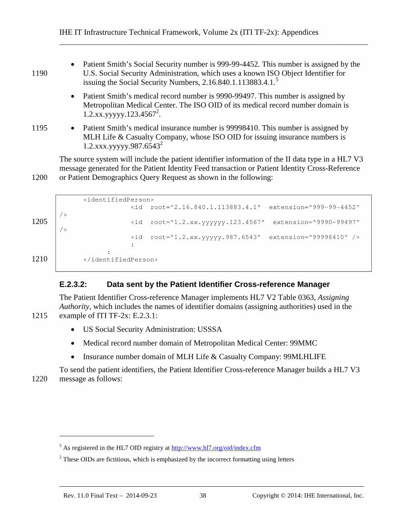
IHE IT Infrastructure Technical Framework, Volume 2x (ITI TF-2x): Appendices ______________________________________________________________________________
_____________________________________________________________________________ Rev. 11.0 Final Text – 2014-09-23 38 Copyright © 2014: IHE International, Inc.
• Patient Smith’s Social Security number is 999-99-4452. This number is assigned by the U.S. Social Security Administration, which uses a known ISO Object Identifier for 1190 issuing the Social Security Numbers, 2.16.840.1.113883.4.1.5
• Patient Smith’s medical record number is 9990-99497. This number is assigned by Metropolitan Medical Center. The ISO OID of its medical record number domain is 1.2.xx.yyyyy.123.45672.
• Patient Smith’s medical insurance number is 99998410. This number is assigned by 1195 MLH Life & Casualty Company, whose ISO OID for issuing insurance numbers is 1.2.xxx.yyyyy.987.65432
The source system will include the patient identifier information of the II data type in a HL7 V3 message generated for the Patient Identity Feed transaction or Patient Identity Cross-Reference or Patient Demographics Query Request as shown in the following: 1200 <identifiedPerson> <id root="2.16.840.1.113883.4.1" extension="999-99-4452" /> <id root="1.2.xx.yyyyyy.123.4567" extension="9990-99497" 1205 /> <id root="1.2.xx.yyyyy.987.6543" extension="99998410" /> : : </identifiedPerson> 1210
E.2.3.2: Data sent by the Patient Identifier Cross-reference Manager The Patient Identifier Cross-reference Manager implements HL7 V2 Table 0363, Assigning Authority, which includes the names of identifier domains (assigning authorities) used in the example of ITI TF-2x: E.2.3.1: 1215
• US Social Security Administration: USSSA
• Medical record number domain of Metropolitan Medical Center: 99MMC
• Insurance number domain of MLH Life & Casualty Company: 99MLHLIFE To send the patient identifiers, the Patient Identifier Cross-reference Manager builds a HL7 V3 message as follows: 1220
5 As registered in the HL7 OID registry at http://www.hl7.org/oid/index.cfm 2 These OIDs are fictitious, which is emphasized by the incorrect formatting using letters
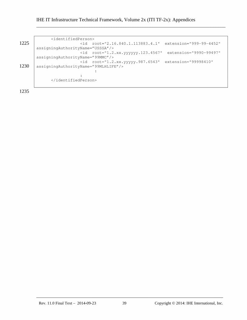
IHE IT Infrastructure Technical Framework, Volume 2x (ITI TF-2x): Appendices ______________________________________________________________________________
_____________________________________________________________________________ Rev. 11.0 Final Text – 2014-09-23 39 Copyright © 2014: IHE International, Inc.
<identifiedPerson> <id root="2.16.840.1.113883.4.1" extension="999-99-4452" 1225 assigningAuthorityName=”USSSA”/> <id root="1.2.xx.yyyyyy.123.4567" extension="9990-99497" assigningAuthorityName=”99MMC”/> <id root="1.2.xx.yyyyy.987.6543" extension="99998410" assigningAuthorityName=”99MLHLIFE”/> 1230 : : </identifiedPerson>
1235
IHE IT Infrastructure Technical Framework, Volume 2x (ITI TF-2x): Appendices ______________________________________________________________________________
_____________________________________________________________________________ Rev. 11.0 Final Text – 2014-09-23 40 Copyright © 2014: IHE International, Inc.
Appendix F: Character String Comparisons All metadata character string comparisons shall be done in conformance with the rules of the Unicode standard (http://www.unicode.org/versions/latest/) using the normalized form C defined in Unicode Technical Report 15 (http://unicode.org/reports/tr15). All XML ID comparisons and OID comparisons shall be compared in a case sensitive way. 1240
Note: Latin alphabet case-sensitive NFC matching corresponds to byte string matching. The primary impact of this is for non-Latin alphabets. They need to be converted into normalized form before comparison. The TR 15 approach is consistent with the working documents of W3C, although W3C has not yet issued a balloted recommendation that Unicode normalized form C be used. See http://www.w3.org/TR/WD-charreq, http://www.w3.org/International/charlint/, and the current W3C draft (http://www.w3.org/TR/charmod-norm). 1245
IHE IT Infrastructure Technical Framework, Volume 2x (ITI TF-2x): Appendices ______________________________________________________________________________
_____________________________________________________________________________ Rev. 11.0 Final Text – 2014-09-23 41 Copyright © 2014: IHE International, Inc.
Appendix G: Transition from Radiology Basic Security to ATNA Retired. The previous appendix G was an XSLT that demonstrated the format translation from the Basic Radiology Schema to the RFC-3881 Schema. It did not generate the correct controlled 1250 vocabulary terms. This caused confusion. A variety of techniques can be used to perform this conversion. The IHE ITI Technical Framework does not specify any particular technique that should be used or will be maintained.
IHE IT Infrastructure Technical Framework, Volume 2x (ITI TF-2x): Appendices ______________________________________________________________________________
_____________________________________________________________________________ Rev. 11.0 Final Text – 2014-09-23 42 Copyright © 2014: IHE International, Inc.
Appendix H: Intentionally Left Blank 1255

IHE IT Infrastructure Technical Framework, Volume 2x (ITI TF-2x): Appendices ______________________________________________________________________________
_____________________________________________________________________________ Rev. 11.0 Final Text – 2014-09-23 43 Copyright © 2014: IHE International, Inc.
Appendix I: Intentionally Left Blank

IHE IT Infrastructure Technical Framework, Volume 2x (ITI TF-2x): Appendices ______________________________________________________________________________
_____________________________________________________________________________ Rev. 11.0 Final Text – 2014-09-23 44 Copyright © 2014: IHE International, Inc.
Appendix J: Intentionally Left Blank 1260
IHE IT Infrastructure Technical Framework, Volume 2x (ITI TF-2x): Appendices ______________________________________________________________________________
_____________________________________________________________________________ Rev. 11.0 Final Text – 2014-09-23 45 Copyright © 2014: IHE International, Inc.
Appendix K: XDS Security Environment This Appendix expands on the summary provided in the XDS specification (ITI TF-1: 10.8). The XDS operations assume that a suitable security and privacy environment has been 1265 established. Almost all of the relevant threats will be managed by agreements, policies, and technologies that are external to the XDS transactions. The few that affect the XDS transactions will be managed by generic security mechanisms that are not unique to XDS. The threats and security objectives that must be addressed are described in Sections K1 and K2 below. Only a few of these have issues that are unique to the XDS application. 1270 Section K3 discusses these few threats and objectives in terms of the agreements and policies that need to be established to create a suitable environment for XDS. Establishing these agreements often involves business agreement discussions that are part of establishing the XDS Affinity Domain. These agreements are necessary because the exchange of documents implies agreeing to the delegation of responsibility for maintaining the security of these documents and 1275 for providing the necessary audit and record keeping facilities.
K.1: Security Environment
K.1.1: Threats Specific threats to the overall XDS system are listed below. These threats are identified using the Common Criteria nomenclature defined by ISO 17799. Most of these are mitigated by policies, 1280 procedures, and technologies that are not unique to XDS and do not require any special XDS considerations. Many of these mitigations do require that the parties within the XDS Affinity Domain have agreement on details of how they will work together. T.ADMIN_ERROR Improper administration may result in defeat of specific security features. T.ADMIN_ROGUE Authorized administrator’s intentions may become malicious resulting in 1285 TSF data to be compromised. T.AUDIT_CORRUPT A malicious process or user may cause audit records to be lost or modified, or prevent future records from being recorded by taking actions to exhaust audit storage capacity, thus masking an attacker’s actions. T.CONFIG_CORRUPT A malicious process or user may cause configuration data or other 1290 trusted data to be lost or modified. T.DISASTER System or network may failure due to disaster (e.g., fire, earthquake). T.DOS A malicious process or user may block others from system resources via a resource exhaustion denial of service attack. T.EAVESDROP A malicious process or user may intercept transmitted data inside or 1295 outside of the enclave. Some of the XDS environments are not concerned with eavesdrop exposure. They may employ external protective mechanisms such as physical network security or VPNs to protect against eavesdropping. T.HARDWARE Hardware may malfunction.
IHE IT Infrastructure Technical Framework, Volume 2x (ITI TF-2x): Appendices ______________________________________________________________________________
_____________________________________________________________________________ Rev. 11.0 Final Text – 2014-09-23 46 Copyright © 2014: IHE International, Inc.
T.IMPROPER_INSTALLATION XDS components may be delivered, installed, or 1300 configured in a manner that undermines security. T.INSECURE_START Reboot may result in insecure state of the operating system. T.INTRUSION Malicious software (e.g., virus) may be introduced into the system. T.MASQUERADE A malicious process or user on one machine on the network may masquerade as an entity on another machine on the same network. 1305 T.OBJECTS_NOT_CLEAN Systems may not adequately remove the data from objects between usage by different users, thereby releasing information to a user unauthorized for the data. This also includes swapping hard disk with PHI during service and repair. T.POOR_DESIGN Unintentional or intentional errors in requirement specification, design or development of the TOE components may occur. 1310 T.POOR_IMPLEMENTATION Unintentional or intentional errors in implementing the design of the XDS environment may occur. T.POOR_TEST Incorrect system behavior may result from inability to demonstrate that all functions and interactions within the XDS operation are correct. T.REPLAY A malicious process or user may gain access by replaying authentication (or 1315 other) information. T.SPOOFING A hostile entity may masquerade itself as part of the XDS Affinity Domain and communicate with authorized users who incorrectly believe they are communicating with authorized members. T.SYSACC A malicious process or user may gain unauthorized access to the administrator 1320 account, or that of other trusted personnel. T.UNATTENDED_SESSION A malicious process or user may gain unauthorized access to an unattended session. T.UNAUTH_ACCESS Unauthorized access to data by a user may occur. This includes access via direct user interaction with the device, access via network transactions, and access via 1325 removable electronic and printed media. T.UNAUTH_MODIFICATION Unauthorized modification or use of XDS attributes and resources may occur. T.UNDETECTED_ACTIONS Failure of the XDS components to detect and record unauthorized actions may occur. 1330 T.UNIDENTIFIED_ACTIONS Failure of the administrator to identify and act upon unauthorized actions may occur. T.UNKNOWN_STATE Upon failure of XDS components, the security of the XDS environment may be unknown. T.USER_CORRUPT User data may be lost or tampered with by other users. 1335
K.1.2: Security and Privacy Policy
IHE IT Infrastructure Technical Framework, Volume 2x (ITI TF-2x): Appendices ______________________________________________________________________________
_____________________________________________________________________________ Rev. 11.0 Final Text – 2014-09-23 47 Copyright © 2014: IHE International, Inc.
There are a wide variety of security and privacy regulations established by law and regulation. These are interpreted and extended to create individual enterprise policies. This equipment will be installed into a variety of enterprises that are subject to a variety of laws and regulations. The XDS environment will provide support for the common aspects of these enterprise policies. The 1340 policy statements whose enforcement must be provided by the XDS security mechanisms are: P.ACCOUNT The users of the system shall be held accountable for their actions within the system. P.AUTHORIZATION The system must limit the extent of each user’s abilities in accordance with the TSPP. (See P.PATIENT_CARE) 1345 P.AUTHORIZED_USERS Only those users who have been authorized to access the information within the system may access the system. (See P.PATIENT_CARE) P.CRYPTOGRAPHY The system shall use standard approved cryptography (methods and implementations) for key management (i.e., generation, access, distribution, destruction, handling, and storage of keys) and cryptographic services (i.e., encryption, decryption, signature, 1350 hashing, key exchange, and random number generation services). P.DECLARATIVE_SECURITY The system shall allow the administrator to define security related rules. Examples include defining access control policies and password expiration restriction. P.I_AND_A All users must be identified and authenticated prior to accessing any controlled 1355 resources with the exception of public objects. P.OBJECTAUTHORIZATION The XDS components must enforce the policy regarding how authorization is established for protected objects. The policy determines how access control and other policies are enforced. (This is often considered part of P.Authorization, but in the XDS context it may make sense to consider this as a separate policy.) 1360 P.PATIENT_CARE The security and privacy measures should not prevent patient care. In particular, there should be emergency bypass mechanisms to override security when necessary to provide patient care. P.SYSTEM_INTEGRITY The system must have the ability to periodically validate its correct operation and, with the help of Administrators, Backup and Restore Operators, and Service 1365 Personnel, it must be able to recover from any errors that are detected. P.TRACE The primary method for enforcing the security and privacy policy is the use of auditing. The XDS components must have the ability to review the actions of individuals. The XDS environment must provide sufficient audit information to external audit and monitoring systems to permit the review of actions of individuals by that other system. 1370 P.TRUSTED_RECOVERY Procedures and/or mechanisms shall be provided to assure that, after a system failure or other discontinuity, recovery without a protection compromise is obtained P.VULNERABILITY_SEARCH The XDS environment must undergo an analysis for vulnerabilities beyond those that are obvious. 1375
IHE IT Infrastructure Technical Framework, Volume 2x (ITI TF-2x): Appendices ______________________________________________________________________________
_____________________________________________________________________________ Rev. 11.0 Final Text – 2014-09-23 48 Copyright © 2014: IHE International, Inc.
K.1.3: Security Usage Assumptions Assumptions of the use of the XDS environment: A.PHYSICAL It is assumed that appropriate physical security is provided within the domain for the value of the IT assets and the value of the stored, processed, and transmitted information. 1380 A. AUDIT_REVIEW It is assumed that there will be audit repository and review services provided that can accept audit information from the XDS components in real time. A.OPERATION It is assumed that networks, firewalls, etc. are deployed and maintained to meet appropriate network security levels. A.PERSONNEL It is assumed that the organization can assure IT user & other 1385 workforce personal integrity/trustworthiness. A.PKI It is assumed that there will be a facility to provide signed certificates as needed for node and user authentication. The key management maybe done manually or automatically depending on the availability of appropriate technology.
K.2: Security Objectives 1390
This section defines the security objectives for the XDS environment. These objectives are suitable to counter all identified threats and cover all identified organizational security policies and assumptions. Common Criteria nomenclature is used. The XDS component security objectives are identified with “O.” appended to at the beginning of the name and the environment objectives are identified with “OE.” appended to the beginning of the name. 1395
K.2.1: XDS Component Security Objectives O.ACCESS The XDS components will ensure that users gain only authorized access to it and to the resources that it controls. (See O.EMERGENCY_BYPASS) O.ACCESS_HISTORY The XDS components will display information (to authorized users) related to previous attempts to establish a session. 1400 O.ADMIN_ROLE The XDS components will provide separate administrator roles to isolate administrative actions. These include a General Administrator role, a Backup and Restore Operator role, a Cryptographic Administrator role, and a Service Personnel role. Additional roles can be defined. These roles are collectively called Administrators. O.ADMIN_TRAINED The XDS components will provide authorized Administrators with 1405 the necessary information for secure management and operation. O.AUDIT_GENERATION The XDS components will provide the capability to detect and create records of security and privacy relevant events associated with users. The XDS components will reliably transmit this information to the central audit repository, and provide reliable local storage of events until the central audit repository has confirmed receipt. (See 1410 OE.AUDIT_REVIEW) O.AUDIT_PROTECTION Each XDS component will provide the capability to protect audit information within its scope of control.
IHE IT Infrastructure Technical Framework, Volume 2x (ITI TF-2x): Appendices ______________________________________________________________________________
_____________________________________________________________________________ Rev. 11.0 Final Text – 2014-09-23 49 Copyright © 2014: IHE International, Inc.
O.AUDIT_REVIEW If an external central audit repository is not part of the environment, the components will be configured to provide limited capability to analyze and 1415 selectively view audit information. (See OE.AUDIT_REVIEW) O.CONFIG_MGMT All changes to the components and its development evidence will be tracked and controlled. O.DECLARATIVE_SECURITY The components will allow security functions and access control to be defined by the authorized administrator. 1420 O.DISASTER_RECOVERY The components should allow the authorized Administrators to perform backup and restore of electronic data, and rapid configuration and reconfiguration of device operation. In addition, the TOE should support administrative procedures to restore operation after disasters that may have substantially destroyed portions of the hospital operation and where substitute temporary systems are in place. 1425 O.DISCRETIONARY_ACCESS The components will control accesses to resources based upon the identity of users and the role of users. (See O.EMERGENCY_BYPASS) O.DISCRETIONARY_USER_CONTROL The components will allow authorized users to specify which resources may be accessed by which users and groups of users. (See O.EMERGENCY_BYPASS) 1430 O.EMERGENCY_BYPASS The XDS components should allow access to any secured data during a declared medical emergency. O.ENCRYPTED_CHANNEL Based on the environmental policies, encryption may be used to provide confidentiality of protected data in transit over public network. O.INSTALL The XDS components will be delivered with the appropriate installation guidance 1435 in the form of installation manuals and training to establish and maintain component security. O.INTRUSION_DETECTION The XDS components will ensure intrusion of malicious software (e.g., virus) is detected. O.MANAGE The XDS components will provide all the functions and facilities necessary to support the authorized Administrators in their management of the security of the TOE. 1440 O.PROTECT The XDS components will provide means to protect user data and resources. O.RECOVERY Procedures and/or mechanisms will be provided to assure that recovery is obtained without a protection compromise, such as from system failure or discontinuity. O.REMOTE_SERVICE The XDS components will provide the means for remote service 1445 without sacrificing security or privacy policy. O.RESIDUAL_INFORMATION The XDS components will ensure that any information contained in a protected resource is not released when the resource is reallocated. Information on permanent media such as hard disk shall be secured during service and repair. O.RESOURCE_SHARING No user will block others from accessing resources. 1450
IHE IT Infrastructure Technical Framework, Volume 2x (ITI TF-2x): Appendices ______________________________________________________________________________
_____________________________________________________________________________ Rev. 11.0 Final Text – 2014-09-23 50 Copyright © 2014: IHE International, Inc.
O.SELF_PROTECTION Each XDS component will maintain a domain for its own execution that protects itself and its resources from external interference, tampering, or unauthorized disclosure. O.TRAINED_USERS The XDS environment will provide authorized users with the necessary guidance for secure operation. 1455 O.TRUSTED_PATH The TOE will provide a means to ensure users are not communicating with some other entity pretending to be the TOE. This covers entity authentication. (See O.USER_AUTHENTICATION.) O.TRUSTED_SYSTEM_OPERATION The XDS components will function in a manner that maintains security. 1460 O.USER_AUTHENTICATION The XDS components will verify the claimed identity of the interactive user. (See O.ENTITY_AUTHENTICATION.) O.USER_IDENTIFICATION The XDS components will uniquely identify the interactive users.
K.2.2: Environment Security Objectives 1465 OE.PHYSICAL Physical security will be provided within the domain for the value of the IT assets protected by the XDS environment and the value of the stored, processed, and transmitted information. OE.AUDIT_REVIEW There may be an audit repository and review service provided that can accept audit information from the XDS environment in real time. This facility will provide 1470 review and analysis functions. (See O.AUDIT_GENERATION, O.AUDIT_REVIEW) OE.OPERATION Networks, firewalls, etc. are deployed and maintained to meet appropriate network security levels. OE.PERSONNEL Assure IT user & other workforce personal integrity/trustworthiness. 1475 OE.PKI There will be a facility to provide signed certificates as needed for node and user authentication.
K.3: Functional Environment The XDS can be modeled as having four different organizations that have a delegated responsibility relationship where each organization has a different functional responsibility. In 1480 some configurations a single organization is responsible for two or more of these functions, which makes delegation much easier. This section discusses the major areas that must be solved. The four functions are: Creator – This functional organization has created the PHI and is legally responsible to the patient and others for providing healthcare and for protecting this data. 1485
IHE IT Infrastructure Technical Framework, Volume 2x (ITI TF-2x): Appendices ______________________________________________________________________________
_____________________________________________________________________________ Rev. 11.0 Final Text – 2014-09-23 51 Copyright © 2014: IHE International, Inc.
Repository – This functional organization is responsible for providing access to persistent documents to readers. The creator has delegated responsibility to the repository to provide adequate protection for a subset of the PHI. This subset is called the document. Registry - This functional organization is responsible for providing query services to readers. The creator has delegated responsibility to the registry to provide adequate protection for a 1490 subset of the PHI. This subset is called the metadata. Reader – This functional organization is providing healthcare services that make use of data that is contained in the metadata and the documents. There are three levels of difficulty in delegation. “Trivial” delegation is that where it is not necessary to delegate the responsibility for 1495 implementing the threat mitigation. In those cases it does not matter whether the organizations have the same policy or mitigations. For example, if the registry provides adequate mitigation against the threat of disaster, it need not be concerned with the disaster related policies of the reader. “Easy” delegation is that where the two organizations have the equivalent policies. In those 1500 cases there is an initial difficult phase of discovering that the policies are the same and evaluating that the mitigation strategies are acceptable. This results in a simple binary decision to approve or disapprove a business relationship permitting the exchange of data. With the exception of the three policy classes described as “hard” below, the details of policies are likely to differ, but the goals are sufficiently uniform that a simple business decision can be made. 1505 For the “easy” delegation, the IHE transactions must provide adequate mitigations for the threats so that the business decision to exchange data can be made based simply on review of the partners policies and mitigations. This means that some IHE transactions will have additional security requirements attached. For example, encryption to avoid the threat of eavesdropping may be required. These requirements are not unique to XDS and will be able to use standardized 1510 security features like TLS and VPN tools. These requirements may be significantly different from the usual practice within an enterprise, because of the differences in the environment. “Hard” delegation is that where the two organizations have different policies or inconsistent/incompatible mitigation strategies. These are likely to occur for the following policies, where organizations often disagree on the details of the policy goals, and where policies 1515 often change: P.Authorization – The authorized access policies and authorized modification policies often differ, and are often subject to change. The changes that occur are often at a detailed level, e.g., access rights to a particular patient information may change. This means that either there is an agreed mechanism to propagate changes, or an acceptance that policy changes may not be 1520 enforced, or there will be restrictions on the data exchange to avoid delegating responsibility for data that is subject to change. P.Account and P.trace – The policies for accountability and traceability often differ. These are much less subject to change, but it is often difficult to reconcile delegation when these policies differ. This will be an especially difficult issue for repository and registry functions that support 1525 multiple different creator organizations.
IHE IT Infrastructure Technical Framework, Volume 2x (ITI TF-2x): Appendices ______________________________________________________________________________
_____________________________________________________________________________ Rev. 11.0 Final Text – 2014-09-23 52 Copyright © 2014: IHE International, Inc.
P.ObjectAuthorization – The policies regarding creation and modification of access rights often differ. In addition, any of the policy and threat mitigations may be determined to be unacceptable by creator, registry, or repository. In the simple situation where there are only four real world participants this simply means that there is no business relationship. In the more complex world 1530 where the registry or repository are in many relationships with many creators and readers it introduces a serious problem. Either the registry and repository must limit its relationship to that small set of creators and readers that mutually accept all the policies and mitigations of all the other organizations, or there must be a mitigation strategy so that creators can restrict delegations by the registry and repository to only those readers that have policies and mitigations that are 1535 acceptable to the creator. Mitigations for differences include the following: Limit the data exchange to that data where the differences are not significant. For example, highly sensitive data like psychiatric notes might not be shared, while relatively insignificant data like allergy information is shared. 1540 Provide a revocation mechanism to deal with policy changes, so that future delegations can be prohibited. It is often impractical to revoke past delegations because the PHI has already been disclosed. But the revocation mechanism can stop further delegation from taking place. This revocation mechanism must be part of the P.Authorization and P.ObjectAuthorization policies and must be mutually acceptable for this mitigation to be effective. 1545 Trusted third party inspections and audits can sometimes deal with reconciliation of differences in P.Account and P.Trace. An “approved delegation” list identifying acceptable and unacceptable creator/reader pairs can mitigate the repository and registry issues when the reader has incompatible policies with the creator. This does require the creator to accept the approved delegation policy and 1550 implementation of the repository and registry, but it reduces the combinatorial explosion of policy combinations between creators, repositories, registries, and readers into a linear growth in complexity. The “approved delegation” may go further into identification of persons, but this is only a viable path when all parties have policies the easily support delegation of personal responsibility. 1555 Persons are usually required to comply with organizational policies, and organizations generally use roles rather than persons to establish policies. The often viable exception is the special case of the “deny access to person X”. This can be a viable means of dealing with situations involving a conflict of interest. This kind of access denial may be applicable to just a particular subset of the PHI exchanged, (e.g., denying access to an ex-spouse). 1560 These mitigations do not directly change the technical requirements for the XDS transactions. They are policy decisions that may affect how particular actors are configured. The implementation of XDS actors will need to be aware that this kind of site-specific configuration management and policy control will be routinely required. 1565
IHE IT Infrastructure Technical Framework, Volume 2x (ITI TF-2x): Appendices ______________________________________________________________________________
_____________________________________________________________________________ Rev. 11.0 Final Text – 2014-09-23 53 Copyright © 2014: IHE International, Inc.
Appendix L: Relationship of Document Entry Attributes and Document Headers For DocumentEntry relationship to Document Content, please see the IHE PCC Technical 1570 Framework: Volume 2: Section 4; or a specific Document Content Profile.
IHE IT Infrastructure Technical Framework, Volume 2x (ITI TF-2x): Appendices ______________________________________________________________________________
_____________________________________________________________________________ Rev. 11.0 Final Text – 2014-09-23 54 Copyright © 2014: IHE International, Inc.
Appendix M: Using Patient Demographics Query in a Multi-Domain Environment
M.1: HL7 QBP^Q22 Conformance Model The HL7 Find Candidates Query (QBP^Q22) defines a patient demographics query between a 1575 client application and an MPI system (HL7 V2.5, Page 3-64). This implies that the server maintains a master record of the patient demographics, but may know a number of patient identifiers from other domains. In the QBP^Q22 Conformance Statement, QPD-8 (What Domains Returned) is defined as “the set of domains for which identifiers are returned in PID-3” (HL7 V2.5, Page 3-66, second table). 1580 Note that this field does not cite “demographics information in some domains”, but about “identifiers issued in some domains”, and explicitly specifies that these identifiers are returned in PID-3 (Patient ID List). In the example following the Conformance Statement in HL7 2.5, three patient records are included in the query response; each returned patient record includes two identifiers in PID-3 1585 (domains METRO HOSPITAL and SOUTH LAB) as requested in the query. However, one set of demographic information is returned in the remainder of the PID segment. The example does not illustrate or assume a mechanism for returning multiple sets of demographic information. Thus it appears that QBP^Q22 is not intended to provide a way to issue a single query for patient demographics maintained in multiple different patient registration systems (domains). 1590
M.2: IHE PDQ Architecture In the PDQ Integration Profile, the supplier is characterized as a Patient Demographics Supplier. The supplier is not assumed nor required to be an MPI system. It may be holding information from only a single patient identification domain, or may instead hold information from multiple identification domains. 1595 The latter case would apply if, for example, the Patient Demographics Supplier is grouped with an actor accepting ADT feeds from multiple patient registration systems in different domains. Equivalently, the Patient Demographics Supplier Actor (or some other Actor with which it is grouped) may manage a set of patient demographics sources, but is not expected to cross-reference them (as a PIX Actor or an MPI system). A conceptual model embracing both multi-1600 domain concepts is shown in the following picture.
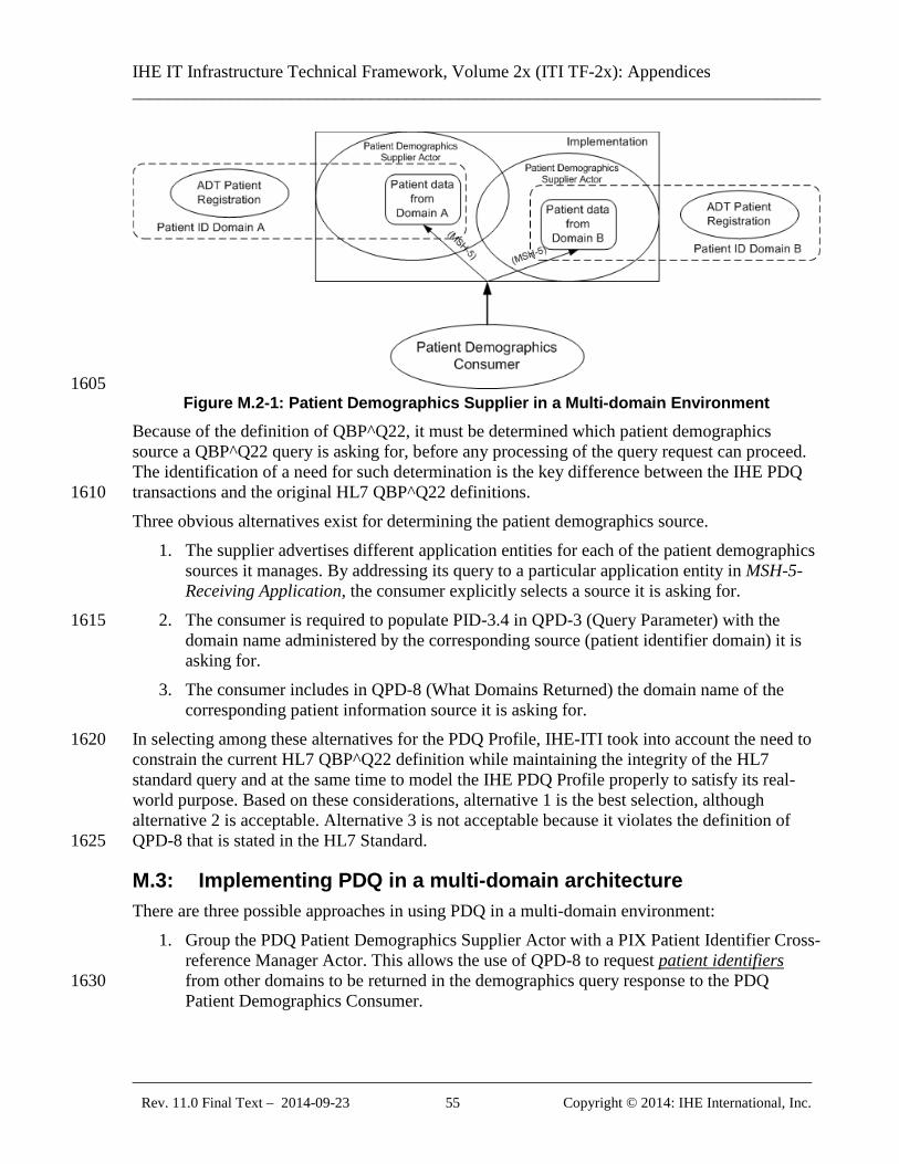
IHE IT Infrastructure Technical Framework, Volume 2x (ITI TF-2x): Appendices ______________________________________________________________________________
_____________________________________________________________________________ Rev. 11.0 Final Text – 2014-09-23 55 Copyright © 2014: IHE International, Inc.
1605 Figure M.2-1: Patient Demographics Supplier in a Multi-domain Environment
Because of the definition of QBP^Q22, it must be determined which patient demographics source a QBP^Q22 query is asking for, before any processing of the query request can proceed. The identification of a need for such determination is the key difference between the IHE PDQ transactions and the original HL7 QBP^Q22 definitions. 1610 Three obvious alternatives exist for determining the patient demographics source.
1. The supplier advertises different application entities for each of the patient demographics sources it manages. By addressing its query to a particular application entity in MSH-5-Receiving Application, the consumer explicitly selects a source it is asking for.
2. The consumer is required to populate PID-3.4 in QPD-3 (Query Parameter) with the 1615 domain name administered by the corresponding source (patient identifier domain) it is asking for.
3. The consumer includes in QPD-8 (What Domains Returned) the domain name of the corresponding patient information source it is asking for.
In selecting among these alternatives for the PDQ Profile, IHE-ITI took into account the need to 1620 constrain the current HL7 QBP^Q22 definition while maintaining the integrity of the HL7 standard query and at the same time to model the IHE PDQ Profile properly to satisfy its real-world purpose. Based on these considerations, alternative 1 is the best selection, although alternative 2 is acceptable. Alternative 3 is not acceptable because it violates the definition of QPD-8 that is stated in the HL7 Standard. 1625
M.3: Implementing PDQ in a multi-domain architecture There are three possible approaches in using PDQ in a multi-domain environment:
1. Group the PDQ Patient Demographics Supplier Actor with a PIX Patient Identifier Cross-reference Manager Actor. This allows the use of QPD-8 to request patient identifiers from other domains to be returned in the demographics query response to the PDQ 1630 Patient Demographics Consumer.
IHE IT Infrastructure Technical Framework, Volume 2x (ITI TF-2x): Appendices ______________________________________________________________________________
_____________________________________________________________________________ Rev. 11.0 Final Text – 2014-09-23 56 Copyright © 2014: IHE International, Inc.
2. Group the PDQ Patient Demographics Supplier Actor with a PIX Patient Identifier Cross-reference Consumer Actor. This allows the use of QPD-8 to request patient identifiers from other domains to be returned in the demographics query response to the PDQ Patient Demographics Consumer. 1635
3. Group the PDQ Patient Demographics Consumer Actor with a PIX Patient Identifier Cross-reference Consumer Actor. This obliges the Patient Demographics Consumer to use separate query requests to obtain patient demographics information (PDQ query) and patient identifiers from the domains in which it is interested (PIX query).
Approach 3 is not recommended if Approach 1 or 2 is feasible. To require the Patient 1640 Demographics Consumer to issue a separate PIX query increases complexity and might not be permissible in the actual implementation architecture. When Approach 1 or 2 is implemented, QPD-8 may be used by the Patient Demographics Consumer to ask for patient identifiers from the single domain used to identify patients in the Affinity Domain.. The patient demographics information returned comes from the patient 1645 demographics source that is associated with MSH-5-Receiving Application; the patient demographics source may or may not be associated with the patient identifier domain. In Approach 2, note that the PDQ Patient Demographics Supplier is grouped with the PIX Patient Identifier Cross-reference Consumer. This combined actor will use a PIX Query to satisfy the request of the client from additional patient identifiers and return them in PID-3. 1650
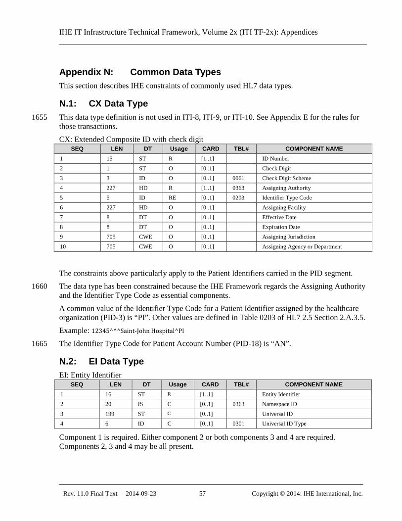
IHE IT Infrastructure Technical Framework, Volume 2x (ITI TF-2x): Appendices ______________________________________________________________________________
_____________________________________________________________________________ Rev. 11.0 Final Text – 2014-09-23 57 Copyright © 2014: IHE International, Inc.
Appendix N: Common Data Types This section describes IHE constraints of commonly used HL7 data types.
N.1: CX Data Type This data type definition is not used in ITI-8, ITI-9, or ITI-10. See Appendix E for the rules for 1655 those transactions. CX: Extended Composite ID with check digit
SEQ LEN DT Usage CARD TBL# COMPONENT NAME 1 15 ST R [1..1] ID Number 2 1 ST O [0..1] Check Digit 3 3 ID O [0..1] 0061 Check Digit Scheme 4 227 HD R [1..1] 0363 Assigning Authority 5 5 ID RE [0..1] 0203 Identifier Type Code 6 227 HD O [0..1] Assigning Facility 7 8 DT O [0..1] Effective Date 8 8 DT O [0..1] Expiration Date 9 705 CWE O [0..1] Assigning Jurisdiction 10 705 CWE O [0..1] Assigning Agency or Department
The constraints above particularly apply to the Patient Identifiers carried in the PID segment. The data type has been constrained because the IHE Framework regards the Assigning Authority 1660 and the Identifier Type Code as essential components. A common value of the Identifier Type Code for a Patient Identifier assigned by the healthcare organization (PID-3) is “PI”. Other values are defined in Table 0203 of HL7 2.5 Section 2.A.3.5. Example: 12345^^^Saint-John Hospital^PI The Identifier Type Code for Patient Account Number (PID-18) is “AN”. 1665
N.2: EI Data Type EI: Entity Identifier
SEQ LEN DT Usage CARD TBL# COMPONENT NAME 1 16 ST R [1..1] Entity Identifier 2 20 IS C [0..1] 0363 Namespace ID 3 199 ST C [0..1] Universal ID 4 6 ID C [0..1] 0301 Universal ID Type
Component 1 is required. Either component 2 or both components 3 and 4 are required. Components 2, 3 and 4 may be all present.
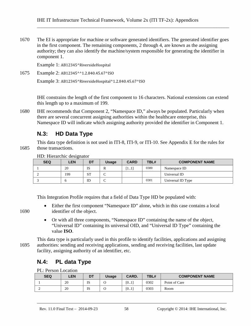
IHE IT Infrastructure Technical Framework, Volume 2x (ITI TF-2x): Appendices ______________________________________________________________________________
_____________________________________________________________________________ Rev. 11.0 Final Text – 2014-09-23 58 Copyright © 2014: IHE International, Inc.
The EI is appropriate for machine or software generated identifiers. The generated identifier goes 1670 in the first component. The remaining components, 2 through 4, are known as the assigning authority; they can also identify the machine/system responsible for generating the identifier in component 1. Example 1: AB12345^RiversideHospital Example 2: AB12345^^1.2.840.45.67^ISO 1675 Example 3: AB12345^RiversideHospital^1.2.840.45.67^ISO IHE constrains the length of the first component to 16 characters. National extensions can extend this length up to a maximum of 199. IHE recommends that Component 2, “Namespace ID,” always be populated. Particularly when 1680 there are several concurrent assigning authorities within the healthcare enterprise, this Namespace ID will indicate which assigning authority provided the identifier in Component 1.
N.3: HD Data Type This data type definition is not used in ITI-8, ITI-9, or ITI-10. See Appendix E for the rules for those transactions. 1685 HD: Hierarchic designator
SEQ LEN DT Usage CARD TBL# COMPONENT NAME 1 20 IS R [1..1] 0300 Namespace ID 2 199 ST C Universal ID 3 6 ID C 0301 Universal ID Type
This Integration Profile requires that a field of Data Type HD be populated with:
• Either the first component “Namespace ID” alone, which in this case contains a local identifier of the object. 1690
• Or with all three components, “Namespace ID” containing the name of the object, “Universal ID” containing its universal OID, and “Universal ID Type” containing the value ISO.
This data type is particularly used in this profile to identify facilities, applications and assigning authorities: sending and receiving applications, sending and receiving facilities, last update 1695 facility, assigning authority of an identifier, etc.
N.4: PL data Type PL: Person Location
SEQ LEN DT Usage CARD. TBL# COMPONENT NAME 1 20 IS O [0..1] 0302 Point of Care 2 20 IS O [0..1] 0303 Room
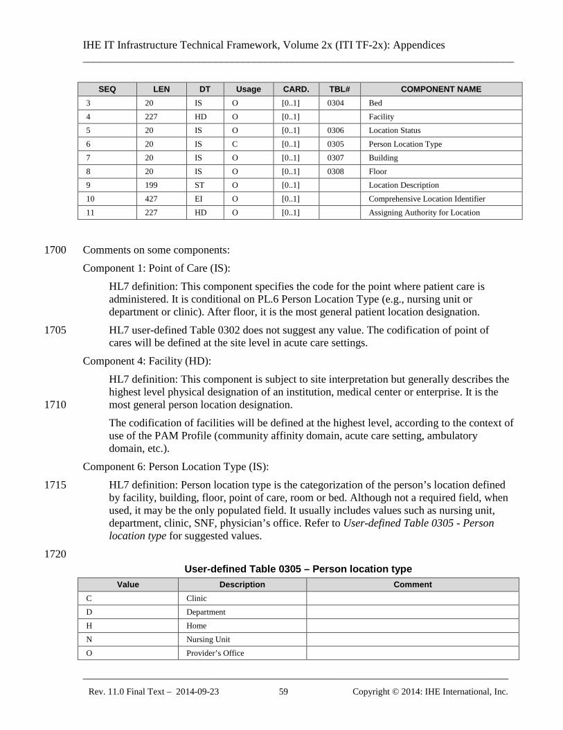
IHE IT Infrastructure Technical Framework, Volume 2x (ITI TF-2x): Appendices ______________________________________________________________________________
_____________________________________________________________________________ Rev. 11.0 Final Text – 2014-09-23 59 Copyright © 2014: IHE International, Inc.
SEQ LEN DT Usage CARD. TBL# COMPONENT NAME 3 20 IS O [0..1] 0304 Bed 4 227 HD O [0..1] Facility 5 20 IS O [0..1] 0306 Location Status 6 20 IS C [0..1] 0305 Person Location Type 7 20 IS O [0..1] 0307 Building 8 20 IS O [0..1] 0308 Floor 9 199 ST O [0..1] Location Description 10 427 EI O [0..1] Comprehensive Location Identifier 11 227 HD O [0..1] Assigning Authority for Location
Comments on some components: 1700 Component 1: Point of Care (IS):
HL7 definition: This component specifies the code for the point where patient care is administered. It is conditional on PL.6 Person Location Type (e.g., nursing unit or department or clinic). After floor, it is the most general patient location designation. HL7 user-defined Table 0302 does not suggest any value. The codification of point of 1705 cares will be defined at the site level in acute care settings.
Component 4: Facility (HD): HL7 definition: This component is subject to site interpretation but generally describes the highest level physical designation of an institution, medical center or enterprise. It is the most general person location designation. 1710 The codification of facilities will be defined at the highest level, according to the context of use of the PAM Profile (community affinity domain, acute care setting, ambulatory domain, etc.).
Component 6: Person Location Type (IS): HL7 definition: Person location type is the categorization of the person’s location defined 1715 by facility, building, floor, point of care, room or bed. Although not a required field, when used, it may be the only populated field. It usually includes values such as nursing unit, department, clinic, SNF, physician’s office. Refer to User-defined Table 0305 - Person location type for suggested values. 1720
User-defined Table 0305 – Person location type Value Description Comment
C Clinic D Department H Home N Nursing Unit O Provider’s Office
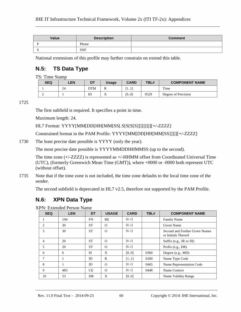
IHE IT Infrastructure Technical Framework, Volume 2x (ITI TF-2x): Appendices ______________________________________________________________________________
_____________________________________________________________________________ Rev. 11.0 Final Text – 2014-09-23 60 Copyright © 2014: IHE International, Inc.
Value Description Comment P Phone S SNF
National extensions of this profile may further constrain on extend this table.
N.5: TS Data Type TS: Time Stamp
SEQ LEN DT Usage CARD TBL# COMPONENT NAME 1 24 DTM R [1..1] Time 2 1 ID X [0..0] 0529 Degree of Precision
1725 The first subfield is required. It specifies a point in time. Maximum length: 24. HL7 Format: YYYY[MM[DD[HH[MM[SS[.S[S[S[S]]]]]]]]][+/-ZZZZ] Constrained format in the PAM Profile: YYYY[MM[DD[HH[MM[SS]]]]][+/-ZZZZ] The least precise date possible is YYYY (only the year). 1730 The most precise date possible is YYYYMMDDHHMMSS (up to the second). The time zone (+/-ZZZZ) is represented as +/-HHMM offset from Coordinated Universal Time (UTC), (formerly Greenwich Mean Time (GMT)), where +0000 or -0000 both represent UTC (without offset). Note that if the time zone is not included, the time zone defaults to the local time zone of the 1735 sender. The second subfield is deprecated in HL7 v2.5, therefore not supported by the PAM Profile.
N.6: XPN Data Type XPN: Extended Person Name
SEQ LEN DT USAGE CARD TBL# COMPONENT NAME 1 194 FN RE [0..1] Family Name 2 30 ST O [0..1] Given Name 3 30 ST O [0..1] Second and Further Given Names
or Initials Thereof 4 20 ST O [0..1] Suffix (e.g., JR or III) 5 20 ST O [0..1] Prefix (e.g., DR) 6 6 IS X [0..0] 0360 Degree (e.g., MD) 7 1 ID R [1..1] 0200 Name Type Code 8 1 ID O [0..1] 0465 Name Representation Code 9 483 CE O [0..1] 0448 Name Context 10 53 DR X [0..0] Name Validity Range
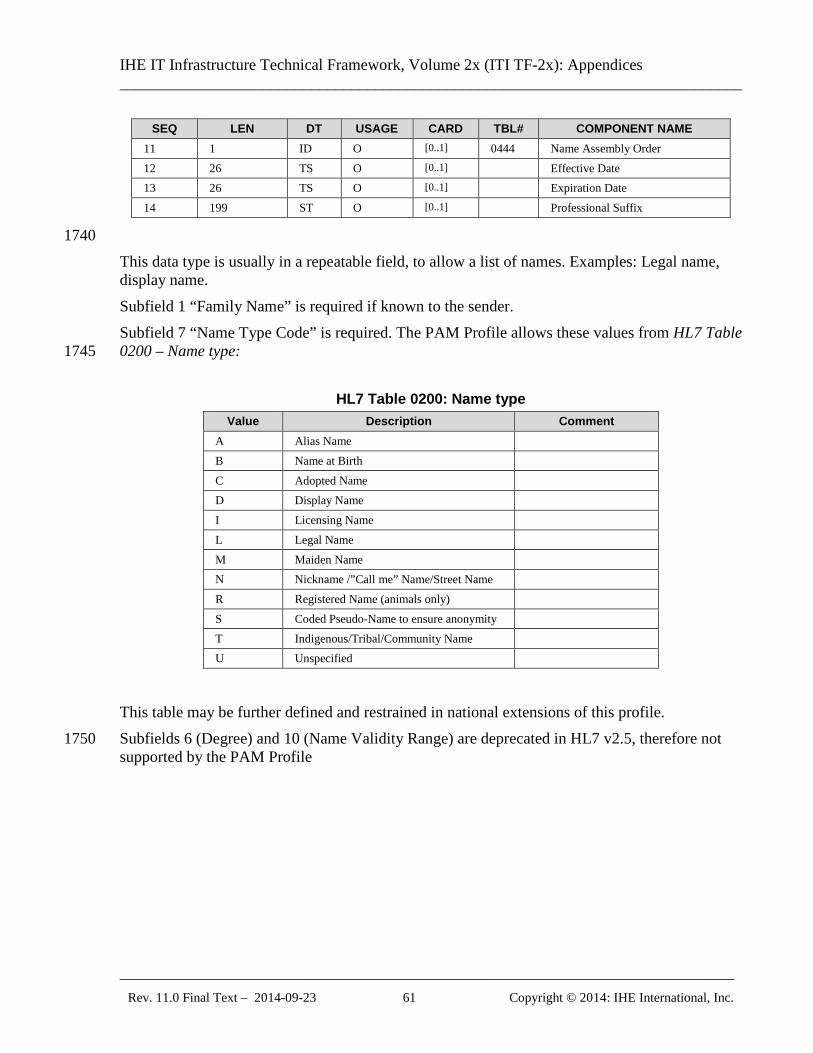
IHE IT Infrastructure Technical Framework, Volume 2x (ITI TF-2x): Appendices ______________________________________________________________________________
_____________________________________________________________________________ Rev. 11.0 Final Text – 2014-09-23 61 Copyright © 2014: IHE International, Inc.
SEQ LEN DT USAGE CARD TBL# COMPONENT NAME 11 1 ID O [0..1] 0444 Name Assembly Order 12 26 TS O [0..1] Effective Date 13 26 TS O [0..1] Expiration Date 14 199 ST O [0..1] Professional Suffix
1740 This data type is usually in a repeatable field, to allow a list of names. Examples: Legal name, display name. Subfield 1 “Family Name” is required if known to the sender. Subfield 7 “Name Type Code” is required. The PAM Profile allows these values from HL7 Table 0200 – Name type: 1745
HL7 Table 0200: Name type Value Description Comment
A Alias Name B Name at Birth C Adopted Name D Display Name I Licensing Name L Legal Name M Maiden Name N Nickname /”Call me” Name/Street Name R Registered Name (animals only) S Coded Pseudo-Name to ensure anonymity T Indigenous/Tribal/Community Name U Unspecified
This table may be further defined and restrained in national extensions of this profile. Subfields 6 (Degree) and 10 (Name Validity Range) are deprecated in HL7 v2.5, therefore not 1750 supported by the PAM Profile
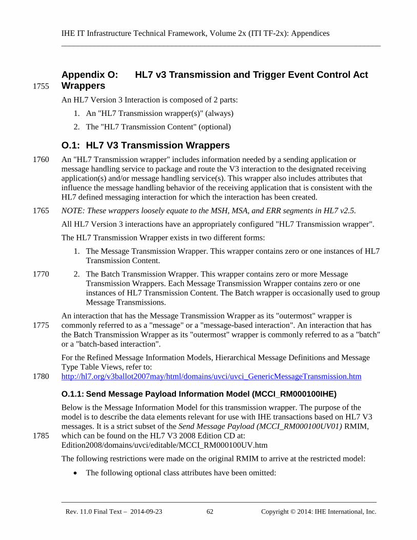
IHE IT Infrastructure Technical Framework, Volume 2x (ITI TF-2x): Appendices ______________________________________________________________________________
_____________________________________________________________________________ Rev. 11.0 Final Text – 2014-09-23 62 Copyright © 2014: IHE International, Inc.
Appendix O: HL7 v3 Transmission and Trigger Event Control Act Wrappers 1755
An HL7 Version 3 Interaction is composed of 2 parts: 1. An "HL7 Transmission wrapper(s)" (always) 2. The "HL7 Transmission Content" (optional)
O.1: HL7 V3 Transmission Wrappers An "HL7 Transmission wrapper" includes information needed by a sending application or 1760 message handling service to package and route the V3 interaction to the designated receiving application(s) and/or message handling service(s). This wrapper also includes attributes that influence the message handling behavior of the receiving application that is consistent with the HL7 defined messaging interaction for which the interaction has been created. NOTE: These wrappers loosely equate to the MSH, MSA, and ERR segments in HL7 v2.5. 1765 All HL7 Version 3 interactions have an appropriately configured "HL7 Transmission wrapper". The HL7 Transmission Wrapper exists in two different forms:
1. The Message Transmission Wrapper. This wrapper contains zero or one instances of HL7 Transmission Content.
2. The Batch Transmission Wrapper. This wrapper contains zero or more Message 1770 Transmission Wrappers. Each Message Transmission Wrapper contains zero or one instances of HL7 Transmission Content. The Batch wrapper is occasionally used to group Message Transmissions.
An interaction that has the Message Transmission Wrapper as its "outermost" wrapper is commonly referred to as a "message" or a "message-based interaction". An interaction that has 1775 the Batch Transmission Wrapper as its "outermost" wrapper is commonly referred to as a "batch" or a "batch-based interaction". For the Refined Message Information Models, Hierarchical Message Definitions and Message Type Table Views, refer to: http://hl7.org/v3ballot2007may/html/domains/uvci/uvci_GenericMessageTransmission.htm 1780
O.1.1: Send Message Payload Information Model (MCCI_RM000100IHE) Below is the Message Information Model for this transmission wrapper. The purpose of the model is to describe the data elements relevant for use with IHE transactions based on HL7 V3 messages. It is a strict subset of the Send Message Payload (MCCI_RM000100UV01) RMIM, which can be found on the HL7 V3 2008 Edition CD at: 1785 Edition2008/domains/uvci/editable/MCCI_RM000100UV.htm The following restrictions were made on the original RMIM to arrive at the restricted model:
• The following optional class attributes have been omitted:
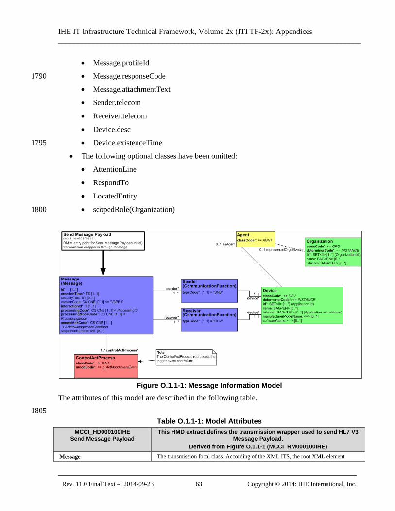
IHE IT Infrastructure Technical Framework, Volume 2x (ITI TF-2x): Appendices ______________________________________________________________________________
_____________________________________________________________________________ Rev. 11.0 Final Text – 2014-09-23 63 Copyright © 2014: IHE International, Inc.
• Message.profileId
• Message.responseCode 1790
• Message.attachmentText
• Sender.telecom
• Receiver.telecom
• Device.desc
• Device.existenceTime 1795
• The following optional classes have been omitted:
• AttentionLine
• RespondTo
• LocatedEntity
• scopedRole(Organization) 1800
Figure O.1.1-1: Message Information Model
The attributes of this model are described in the following table. 1805
Table O.1.1-1: Model Attributes MCCI_HD000100IHE
Send Message Payload This HMD extract defines the transmission wrapper used to send HL7 V3
Message Payload. Derived from Figure O.1.1-1 (MCCI_RM000100IHE)
Message The transmission focal class. According of the XML ITS, the root XML element
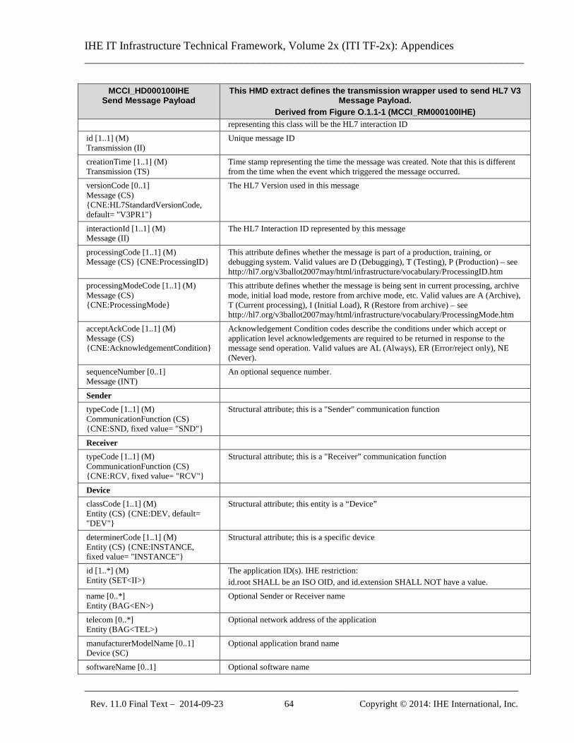
IHE IT Infrastructure Technical Framework, Volume 2x (ITI TF-2x): Appendices ______________________________________________________________________________
_____________________________________________________________________________ Rev. 11.0 Final Text – 2014-09-23 64 Copyright © 2014: IHE International, Inc.
MCCI_HD000100IHE Send Message Payload
This HMD extract defines the transmission wrapper used to send HL7 V3 Message Payload.
Derived from Figure O.1.1-1 (MCCI_RM000100IHE) representing this class will be the HL7 interaction ID
id [1..1] (M) Transmission (II)
Unique message ID
creationTime [1..1] (M) Transmission (TS)
Time stamp representing the time the message was created. Note that this is different from the time when the event which triggered the message occurred.
versionCode [0..1] Message (CS) {CNE:HL7StandardVersionCode, default= "V3PR1"}
The HL7 Version used in this message
interactionId [1..1] (M) Message (II)
The HL7 Interaction ID represented by this message
processingCode [1..1] (M) Message (CS) {CNE:ProcessingID}
This attribute defines whether the message is part of a production, training, or debugging system. Valid values are D (Debugging), T (Testing), P (Production) – see http://hl7.org/v3ballot2007may/html/infrastructure/vocabulary/ProcessingID.htm
processingModeCode [1..1] (M) Message (CS) {CNE:ProcessingMode}
This attribute defines whether the message is being sent in current processing, archive mode, initial load mode, restore from archive mode, etc. Valid values are A (Archive), T (Current processing), I (Initial Load), R (Restore from archive) – see http://hl7.org/v3ballot2007may/html/infrastructure/vocabulary/ProcessingMode.htm
acceptAckCode [1..1] (M) Message (CS) {CNE:AcknowledgementCondition}
Acknowledgement Condition codes describe the conditions under which accept or application level acknowledgements are required to be returned in response to the message send operation. Valid values are AL (Always), ER (Error/reject only), NE (Never).
sequenceNumber [0..1] Message (INT)
An optional sequence number.
Sender typeCode [1..1] (M) CommunicationFunction (CS) {CNE:SND, fixed value= "SND"}
Structural attribute; this is a "Sender" communication function
Receiver typeCode [1..1] (M) CommunicationFunction (CS) {CNE:RCV, fixed value= "RCV"}
Structural attribute; this is a "Receiver” communication function
Device classCode [1..1] (M) Entity (CS) {CNE:DEV, default= "DEV"}
Structural attribute; this entity is a “Device”
determinerCode [1..1] (M) Entity (CS) {CNE:INSTANCE, fixed value= "INSTANCE"}
Structural attribute; this is a specific device
id [1..*] (M) Entity (SET<II>)
The application ID(s). IHE restriction: id.root SHALL be an ISO OID, and id.extension SHALL NOT have a value.
name [0..*] Entity (BAG<EN>)
Optional Sender or Receiver name
telecom [0..*] Entity (BAG<TEL>)
Optional network address of the application
manufacturerModelName [0..1] Device (SC)
Optional application brand name
softwareName [0..1] Optional software name
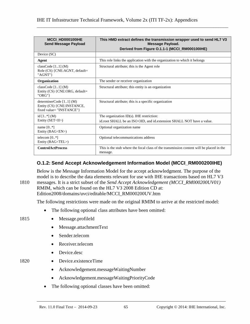
IHE IT Infrastructure Technical Framework, Volume 2x (ITI TF-2x): Appendices ______________________________________________________________________________
_____________________________________________________________________________ Rev. 11.0 Final Text – 2014-09-23 65 Copyright © 2014: IHE International, Inc.
MCCI_HD000100IHE Send Message Payload
This HMD extract defines the transmission wrapper used to send HL7 V3 Message Payload.
Derived from Figure O.1.1-1 (MCCI_RM000100IHE) Device (SC)
Agent This role links the application with the organization to which it belongs classCode [1..1] (M) Role (CS) {CNE:AGNT, default= "AGNT"}
Structural attribute; this is the Agent role
Organization The sender or receiver organization classCode [1..1] (M) Entity (CS) {CNE:ORG, default= "ORG"}
Structural attribute; this entity is an organization
determinerCode [1..1] (M) Entity (CS) {CNE:INSTANCE, fixed value= "INSTANCE"}
Structural attribute; this is a specific organization
id [1..*] (M) Entity (SET<II>)
The organization ID(s). IHE restriction: id.root SHALL be an ISO OID, and id.extension SHALL NOT have a value.
name [0..*] Entity (BAG<EN>)
Optional organization name
telecom [0..*] Entity (BAG<TEL>)
Optional telecommunications address
ControlActProcess This is the stub where the focal class of the transmission content will be placed in the message.
O.1.2: Send Accept Acknowledgement Information Model (MCCI_RM000200IHE) Below is the Message Information Model for the accept acknowledgment. The purpose of the model is to describe the data elements relevant for use with IHE transactions based on HL7 V3 messages. It is a strict subset of the Send Accept Acknowledgement (MCCI_RM000200UV01) 1810 RMIM, which can be found on the HL7 V3 2008 Edition CD at: Edition2008/domains/uvci/editable/MCCI_RM000200UV.htm The following restrictions were made on the original RMIM to arrive at the restricted model:
• The following optional class attributes have been omitted:
• Message.profileId 1815
• Message.attachmentText
• Sender.telecom
• Receiver.telecom
• Device.desc
• Device.existenceTime 1820
• Acknowledgement.messageWaitingNumber
• Acknowledgement.messageWaitingPriorityCode
• The following optional classes have been omitted:
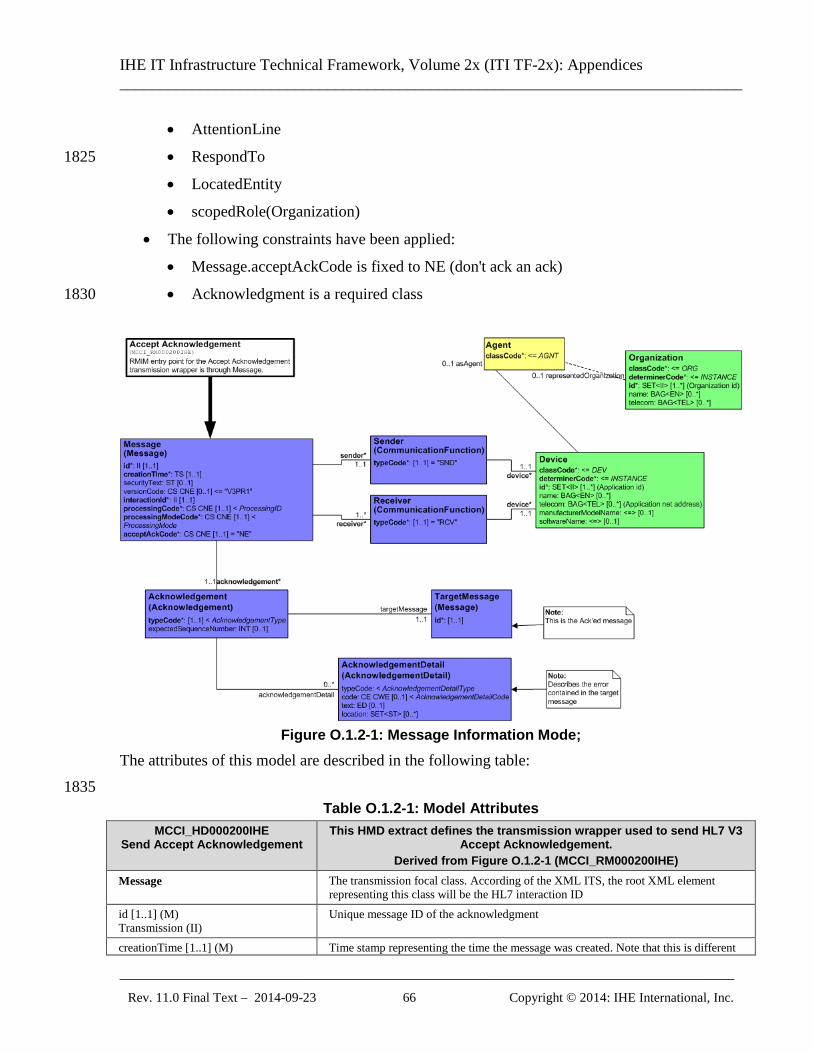
IHE IT Infrastructure Technical Framework, Volume 2x (ITI TF-2x): Appendices ______________________________________________________________________________
_____________________________________________________________________________ Rev. 11.0 Final Text – 2014-09-23 66 Copyright © 2014: IHE International, Inc.
• AttentionLine
• RespondTo 1825
• LocatedEntity
• scopedRole(Organization)
• The following constraints have been applied:
• Message.acceptAckCode is fixed to NE (don't ack an ack)
• Acknowledgment is a required class 1830
Figure O.1.2-1: Message Information Mode;
The attributes of this model are described in the following table: 1835
Table O.1.2-1: Model Attributes MCCI_HD000200IHE
Send Accept Acknowledgement This HMD extract defines the transmission wrapper used to send HL7 V3
Accept Acknowledgement. Derived from Figure O.1.2-1 (MCCI_RM000200IHE)
Message The transmission focal class. According of the XML ITS, the root XML element representing this class will be the HL7 interaction ID
id [1..1] (M) Transmission (II)
Unique message ID of the acknowledgment
creationTime [1..1] (M) Time stamp representing the time the message was created. Note that this is different
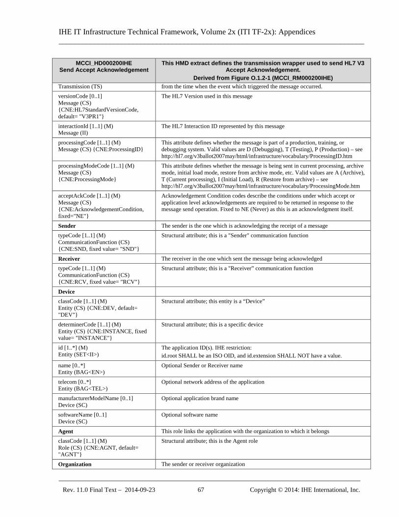
IHE IT Infrastructure Technical Framework, Volume 2x (ITI TF-2x): Appendices ______________________________________________________________________________
_____________________________________________________________________________ Rev. 11.0 Final Text – 2014-09-23 67 Copyright © 2014: IHE International, Inc.
MCCI_HD000200IHE Send Accept Acknowledgement
This HMD extract defines the transmission wrapper used to send HL7 V3 Accept Acknowledgement.
Derived from Figure O.1.2-1 (MCCI_RM000200IHE) Transmission (TS) from the time when the event which triggered the message occurred. versionCode [0..1] Message (CS) {CNE:HL7StandardVersionCode, default= "V3PR1"}
The HL7 Version used in this message
interactionId [1..1] (M) Message (II)
The HL7 Interaction ID represented by this message
processingCode [1..1] (M) Message (CS) {CNE:ProcessingID}
This attribute defines whether the message is part of a production, training, or debugging system. Valid values are D (Debugging), T (Testing), P (Production) – see http://hl7.org/v3ballot2007may/html/infrastructure/vocabulary/ProcessingID.htm
processingModeCode [1..1] (M) Message (CS) {CNE:ProcessingMode}
This attribute defines whether the message is being sent in current processing, archive mode, initial load mode, restore from archive mode, etc. Valid values are A (Archive), T (Current processing), I (Initial Load), R (Restore from archive) – see http://hl7.org/v3ballot2007may/html/infrastructure/vocabulary/ProcessingMode.htm
acceptAckCode [1..1] (M) Message (CS) {CNE:AcknowledgementCondition, fixed="NE"}
Acknowledgement Condition codes describe the conditions under which accept or application level acknowledgements are required to be returned in response to the message send operation. Fixed to NE (Never) as this is an acknowledgment itself.
Sender The sender is the one which is acknowledging the receipt of a message typeCode [1..1] (M) CommunicationFunction (CS) {CNE:SND, fixed value= "SND"}
Structural attribute; this is a "Sender" communication function
Receiver The receiver in the one which sent the message being acknowledged typeCode [1..1] (M) CommunicationFunction (CS) {CNE:RCV, fixed value= "RCV"}
Structural attribute; this is a "Receiver” communication function
Device classCode [1..1] (M) Entity (CS) {CNE:DEV, default= "DEV"}
Structural attribute; this entity is a “Device”
determinerCode [1..1] (M) Entity (CS) {CNE:INSTANCE, fixed value= "INSTANCE"}
Structural attribute; this is a specific device
id [1..*] (M) Entity (SET<II>)
The application ID(s). IHE restriction: id.root SHALL be an ISO OID, and id.extension SHALL NOT have a value.
name [0..*] Entity (BAG<EN>)
Optional Sender or Receiver name
telecom [0..*] Entity (BAG<TEL>)
Optional network address of the application
manufacturerModelName [0..1] Device (SC)
Optional application brand name
softwareName [0..1] Device (SC)
Optional software name
Agent This role links the application with the organization to which it belongs classCode [1..1] (M) Role (CS) {CNE:AGNT, default= "AGNT"}
Structural attribute; this is the Agent role
Organization The sender or receiver organization
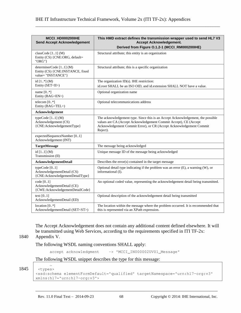
IHE IT Infrastructure Technical Framework, Volume 2x (ITI TF-2x): Appendices ______________________________________________________________________________
_____________________________________________________________________________ Rev. 11.0 Final Text – 2014-09-23 68 Copyright © 2014: IHE International, Inc.
MCCI_HD000200IHE Send Accept Acknowledgement
This HMD extract defines the transmission wrapper used to send HL7 V3 Accept Acknowledgement.
Derived from Figure O.1.2-1 (MCCI_RM000200IHE) classCode [1..1] (M) Entity (CS) {CNE:ORG, default= "ORG"}
Structural attribute; this entity is an organization
determinerCode [1..1] (M) Entity (CS) {CNE:INSTANCE, fixed value= "INSTANCE"}
Structural attribute; this is a specific organization
id [1..*] (M) Entity (SET<II>)
The organization ID(s). IHE restriction: id.root SHALL be an ISO OID, and id.extension SHALL NOT have a value.
name [0..*] Entity (BAG<EN>)
Optional organization name
telecom [0..*] Entity (BAG<TEL>)
Optional telecommunications address
Acknowledgement typeCode [1..1] (M) Acknowledgement (CS) {CNE:AcknowledgementType}
The acknowledgement type. Since this is an Accept Acknowledgement, the possible values are CA (Accept Acknowledgement Commit Accept), CE (Accept Acknowledgement Commit Error), or CR (Accept Acknowledgement Commit Reject).
expectedSequenceNumber [0..1] Acknowledgement (INT)
TargetMessage The message being acknowledged id [1..1] (M) Transmission (II)
Unique message ID of the message being acknowledged
AcknowledgementDetail Describes the error(s) contained in the target message typeCode [0..1] AcknowledgementDetail (CS) {CNE:AcknowledgementDetailType}
Optional detail type indicating if the problem was an error (E), a warning (W), or informational (I).
code [0..1] AcknowledgementDetail (CE) {CWE:AcknowledgementDetailCode}
An optional coded value, representing the acknowledgement detail being transmitted.
text [0..1] AcknowledgementDetail (ED)
Optional description of the acknowledgement detail being transmitted
location [0..*] AcknowledgementDetail (SET<ST>)
The location within the message where the problem occurred. It is recommended that this is represented via an XPath expression.
The Accept Acknowledgement does not contain any additional content defined elsewhere. It will be transmitted using Web Services, according to the requirements specified in ITI TF-2x: Appendix V. 1840 The following WSDL naming conventions SHALL apply: accept acknowledgment -> "MCCI_IN000002UV01_Message"
The following WSDL snippet describes the type for this message: … <types> 1845 <xsd:schema elementFormDefault="qualified" targetNamespace="urn:hl7-org:v3" xmlns:hl7="urn:hl7-org:v3">
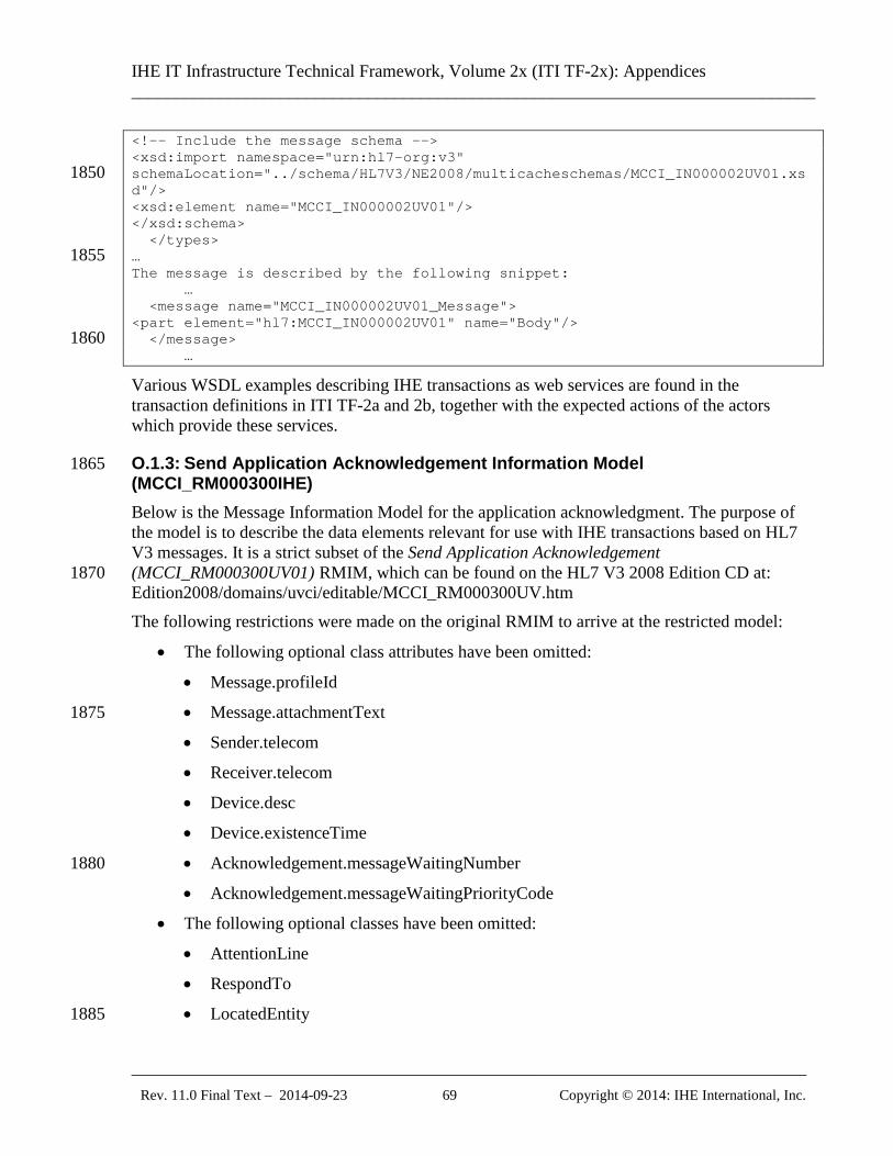
IHE IT Infrastructure Technical Framework, Volume 2x (ITI TF-2x): Appendices ______________________________________________________________________________
_____________________________________________________________________________ Rev. 11.0 Final Text – 2014-09-23 69 Copyright © 2014: IHE International, Inc.
<!-- Include the message schema --> <xsd:import namespace="urn:hl7-org:v3" schemaLocation="../schema/HL7V3/NE2008/multicacheschemas/MCCI_IN000002UV01.xs1850 d"/> <xsd:element name="MCCI_IN000002UV01"/> </xsd:schema> </types> … 1855 The message is described by the following snippet: … <message name="MCCI_IN000002UV01_Message"> <part element="hl7:MCCI_IN000002UV01" name="Body"/> </message> 1860 …
Various WSDL examples describing IHE transactions as web services are found in the transaction definitions in ITI TF-2a and 2b, together with the expected actions of the actors which provide these services.
O.1.3: Send Application Acknowledgement Information Model 1865 (MCCI_RM000300IHE) Below is the Message Information Model for the application acknowledgment. The purpose of the model is to describe the data elements relevant for use with IHE transactions based on HL7 V3 messages. It is a strict subset of the Send Application Acknowledgement (MCCI_RM000300UV01) RMIM, which can be found on the HL7 V3 2008 Edition CD at: 1870 Edition2008/domains/uvci/editable/MCCI_RM000300UV.htm The following restrictions were made on the original RMIM to arrive at the restricted model:
• The following optional class attributes have been omitted:
• Message.profileId
• Message.attachmentText 1875
• Sender.telecom
• Receiver.telecom
• Device.desc
• Device.existenceTime
• Acknowledgement.messageWaitingNumber 1880
• Acknowledgement.messageWaitingPriorityCode
• The following optional classes have been omitted:
• AttentionLine
• RespondTo
• LocatedEntity 1885
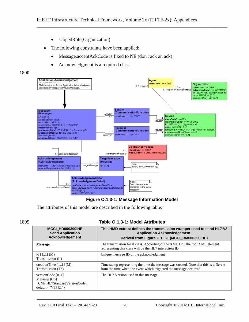
IHE IT Infrastructure Technical Framework, Volume 2x (ITI TF-2x): Appendices ______________________________________________________________________________
_____________________________________________________________________________ Rev. 11.0 Final Text – 2014-09-23 70 Copyright © 2014: IHE International, Inc.
• scopedRole(Organization)
• The following constraints have been applied:
• Message.acceptAckCode is fixed to NE (don't ack an ack)
• Acknowledgment is a required class 1890
Figure O.1.3-1: Message Information Model
The attributes of this model are described in the following table:
Table O.1.3-1: Model Attributes 1895 MCCI_HD000300IHE
Send Application Acknowledgement
This HMD extract defines the transmission wrapper used to send HL7 V3 Application Acknowledgement.
Derived from Figure O.1.3-1 (MCCI_RM000300IHE) Message The transmission focal class. According of the XML ITS, the root XML element
representing this class will be the HL7 interaction ID id [1..1] (M) Transmission (II)
Unique message ID of the acknowledgment
creationTime [1..1] (M) Transmission (TS)
Time stamp representing the time the message was created. Note that this is different from the time when the event which triggered the message occurred.
versionCode [0..1] Message (CS) {CNE:HL7StandardVersionCode, default= "V3PR1"}
The HL7 Version used in this message
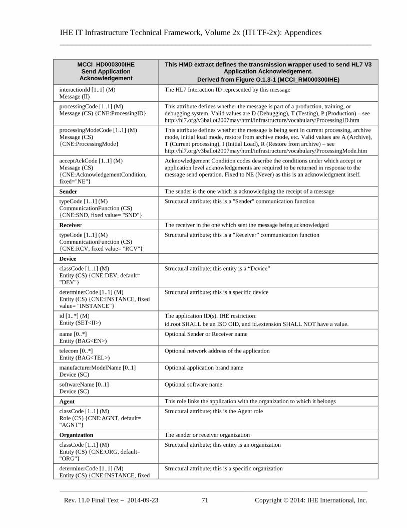
IHE IT Infrastructure Technical Framework, Volume 2x (ITI TF-2x): Appendices ______________________________________________________________________________
_____________________________________________________________________________ Rev. 11.0 Final Text – 2014-09-23 71 Copyright © 2014: IHE International, Inc.
MCCI_HD000300IHE Send Application
Acknowledgement
This HMD extract defines the transmission wrapper used to send HL7 V3 Application Acknowledgement.
Derived from Figure O.1.3-1 (MCCI_RM000300IHE) interactionId [1..1] (M) Message (II)
The HL7 Interaction ID represented by this message
processingCode [1..1] (M) Message (CS) {CNE:ProcessingID}
This attribute defines whether the message is part of a production, training, or debugging system. Valid values are D (Debugging), T (Testing), P (Production) – see http://hl7.org/v3ballot2007may/html/infrastructure/vocabulary/ProcessingID.htm
processingModeCode [1..1] (M) Message (CS) {CNE:ProcessingMode}
This attribute defines whether the message is being sent in current processing, archive mode, initial load mode, restore from archive mode, etc. Valid values are A (Archive), T (Current processing), I (Initial Load), R (Restore from archive) – see http://hl7.org/v3ballot2007may/html/infrastructure/vocabulary/ProcessingMode.htm
acceptAckCode [1..1] (M) Message (CS) {CNE:AcknowledgementCondition, fixed="NE"}
Acknowledgement Condition codes describe the conditions under which accept or application level acknowledgements are required to be returned in response to the message send operation. Fixed to NE (Never) as this is an acknowledgment itself.
Sender The sender is the one which is acknowledging the receipt of a message typeCode [1..1] (M) CommunicationFunction (CS) {CNE:SND, fixed value= "SND"}
Structural attribute; this is a "Sender" communication function
Receiver The receiver in the one which sent the message being acknowledged typeCode [1..1] (M) CommunicationFunction (CS) {CNE:RCV, fixed value= "RCV"}
Structural attribute; this is a "Receiver” communication function
Device classCode [1..1] (M) Entity (CS) {CNE:DEV, default= "DEV"}
Structural attribute; this entity is a “Device”
determinerCode [1..1] (M) Entity (CS) {CNE:INSTANCE, fixed value= "INSTANCE"}
Structural attribute; this is a specific device
id [1..*] (M) Entity (SET<II>)
The application ID(s). IHE restriction: id.root SHALL be an ISO OID, and id.extension SHALL NOT have a value.
name [0..*] Entity (BAG<EN>)
Optional Sender or Receiver name
telecom [0..*] Entity (BAG<TEL>)
Optional network address of the application
manufacturerModelName [0..1] Device (SC)
Optional application brand name
softwareName [0..1] Device (SC)
Optional software name
Agent This role links the application with the organization to which it belongs classCode [1..1] (M) Role (CS) {CNE:AGNT, default= "AGNT"}
Structural attribute; this is the Agent role
Organization The sender or receiver organization classCode [1..1] (M) Entity (CS) {CNE:ORG, default= "ORG"}
Structural attribute; this entity is an organization
determinerCode [1..1] (M) Entity (CS) {CNE:INSTANCE, fixed
Structural attribute; this is a specific organization
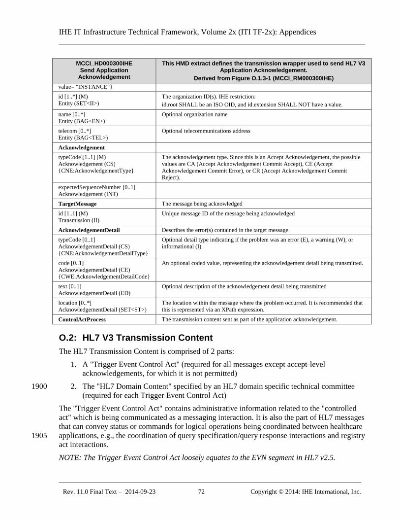
IHE IT Infrastructure Technical Framework, Volume 2x (ITI TF-2x): Appendices ______________________________________________________________________________
_____________________________________________________________________________ Rev. 11.0 Final Text – 2014-09-23 72 Copyright © 2014: IHE International, Inc.
MCCI_HD000300IHE Send Application
Acknowledgement
This HMD extract defines the transmission wrapper used to send HL7 V3 Application Acknowledgement.
Derived from Figure O.1.3-1 (MCCI_RM000300IHE) value= "INSTANCE"} id [1..*] (M) Entity (SET<II>)
The organization ID(s). IHE restriction: id.root SHALL be an ISO OID, and id.extension SHALL NOT have a value.
name [0..*] Entity (BAG<EN>)
Optional organization name
telecom [0..*] Entity (BAG<TEL>)
Optional telecommunications address
Acknowledgement typeCode [1..1] (M) Acknowledgement (CS) {CNE:AcknowledgementType}
The acknowledgement type. Since this is an Accept Acknowledgement, the possible values are CA (Accept Acknowledgement Commit Accept), CE (Accept Acknowledgement Commit Error), or CR (Accept Acknowledgement Commit Reject).
expectedSequenceNumber [0..1] Acknowledgement (INT)
TargetMessage The message being acknowledged id [1..1] (M) Transmission (II)
Unique message ID of the message being acknowledged
AcknowledgementDetail Describes the error(s) contained in the target message typeCode [0..1] AcknowledgementDetail (CS) {CNE:AcknowledgementDetailType}
Optional detail type indicating if the problem was an error (E), a warning (W), or informational (I).
code [0..1] AcknowledgementDetail (CE) {CWE:AcknowledgementDetailCode}
An optional coded value, representing the acknowledgement detail being transmitted.
text [0..1] AcknowledgementDetail (ED)
Optional description of the acknowledgement detail being transmitted
location [0..*] AcknowledgementDetail (SET<ST>)
The location within the message where the problem occurred. It is recommended that this is represented via an XPath expression.
ControlActProcess The transmission content sent as part of the application acknowledgement.
O.2: HL7 V3 Transmission Content The HL7 Transmission Content is comprised of 2 parts:
1. A "Trigger Event Control Act" (required for all messages except accept-level acknowledgements, for which it is not permitted)
2. The "HL7 Domain Content" specified by an HL7 domain specific technical committee 1900 (required for each Trigger Event Control Act)
The "Trigger Event Control Act" contains administrative information related to the "controlled act" which is being communicated as a messaging interaction. It is also the part of HL7 messages that can convey status or commands for logical operations being coordinated between healthcare applications, e.g., the coordination of query specification/query response interactions and registry 1905 act interactions. NOTE: The Trigger Event Control Act loosely equates to the EVN segment in HL7 v2.5.
IHE IT Infrastructure Technical Framework, Volume 2x (ITI TF-2x): Appendices ______________________________________________________________________________
_____________________________________________________________________________ Rev. 11.0 Final Text – 2014-09-23 73 Copyright © 2014: IHE International, Inc.
The "HL7 Domain Content" is the primary domain content of the messaging interaction (when it is present). It contains domain specific content that is specified by an HL7 technical committee to satisfy a use case driven requirement for an HL7 messaging interaction. If an interaction 1910 contains HL7 Domain Content, then it also contains a Trigger Event Control Act. For the Refined Message Information Models, Hierarchical Message Definitions and Message Type Table Views, refer to the HL7 V3 2008 Edition CD at: Edition2008/domains/uvai/uvai_TriggerEventControlAct.htm and Edition2008/domains/uvmi/uvmi_MasterFile-Registry.htm 1915
O.2.1: Master File/Registry Event Notification Control Act (Role Subject) Information Model (MFMI_MT700701IHE) Below is the Message Information Model for this control act wrapper. The purpose of the model is to describe the data elements relevant for use with IHE transactions based on HL7 V3 messages. It is a strict subset of the Master File / Registry Event Notification 1920 (MFMI_RM700700UV01) RMIM, which can be found on the HL7 V3 2008 Edition CD at: Edition2008/domains/uvmi/editable/MFMI_RM700700UV.htm The following restrictions were made on the original RMIM to arrive at the restricted model:
• The following optional class attributes have been omitted:
• ControlActProcess.text 1925
• ControlActProcess.priorityCode
• ControlActProcess.reasonCode
• All participations related to the ControlActProcess have been omitted
• The following act relationships to the RegistrationEvent have been omitted:
• inFulfillmentOf 1930
• definition
• subject2
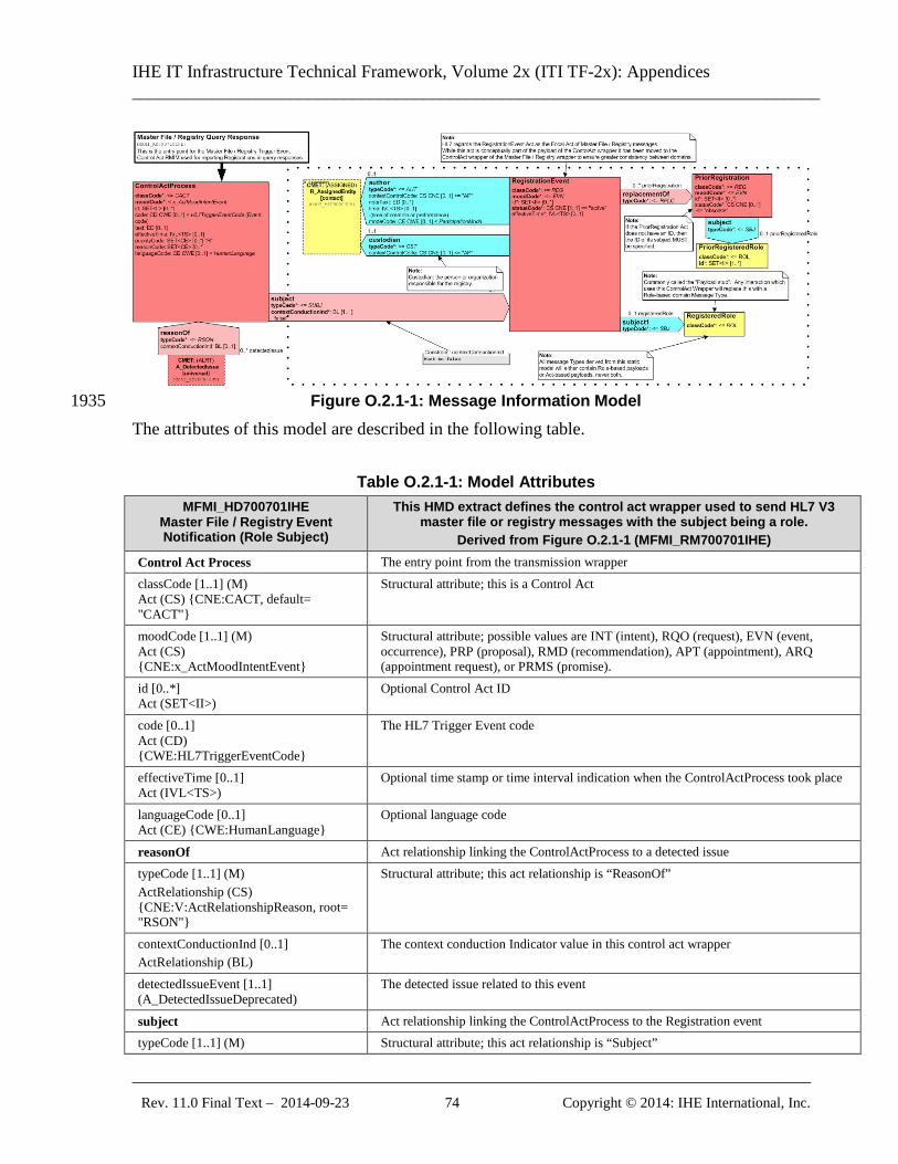
IHE IT Infrastructure Technical Framework, Volume 2x (ITI TF-2x): Appendices ______________________________________________________________________________
_____________________________________________________________________________ Rev. 11.0 Final Text – 2014-09-23 74 Copyright © 2014: IHE International, Inc.
Figure O.2.1-1: Message Information Model 1935
The attributes of this model are described in the following table.
Table O.2.1-1: Model Attributes MFMI_HD700701IHE
Master File / Registry Event Notification (Role Subject)
This HMD extract defines the control act wrapper used to send HL7 V3 master file or registry messages with the subject being a role.
Derived from Figure O.2.1-1 (MFMI_RM700701IHE) Control Act Process The entry point from the transmission wrapper classCode [1..1] (M) Act (CS) {CNE:CACT, default= "CACT"}
Structural attribute; this is a Control Act
moodCode [1..1] (M) Act (CS) {CNE:x_ActMoodIntentEvent}
Structural attribute; possible values are INT (intent), RQO (request), EVN (event, occurrence), PRP (proposal), RMD (recommendation), APT (appointment), ARQ (appointment request), or PRMS (promise).
id [0..*] Act (SET<II>)
Optional Control Act ID
code [0..1] Act (CD) {CWE:HL7TriggerEventCode}
The HL7 Trigger Event code
effectiveTime [0..1] Act (IVL<TS>)
Optional time stamp or time interval indication when the ControlActProcess took place
languageCode [0..1] Act (CE) {CWE:HumanLanguage}
Optional language code
reasonOf Act relationship linking the ControlActProcess to a detected issue typeCode [1..1] (M) ActRelationship (CS) {CNE:V:ActRelationshipReason, root= "RSON"}
Structural attribute; this act relationship is “ReasonOf”
contextConductionInd [0..1] ActRelationship (BL)
The context conduction Indicator value in this control act wrapper
detectedIssueEvent [1..1] (A_DetectedIssueDeprecated)
The detected issue related to this event
subject Act relationship linking the ControlActProcess to the Registration event typeCode [1..1] (M) Structural attribute; this act relationship is “Subject”
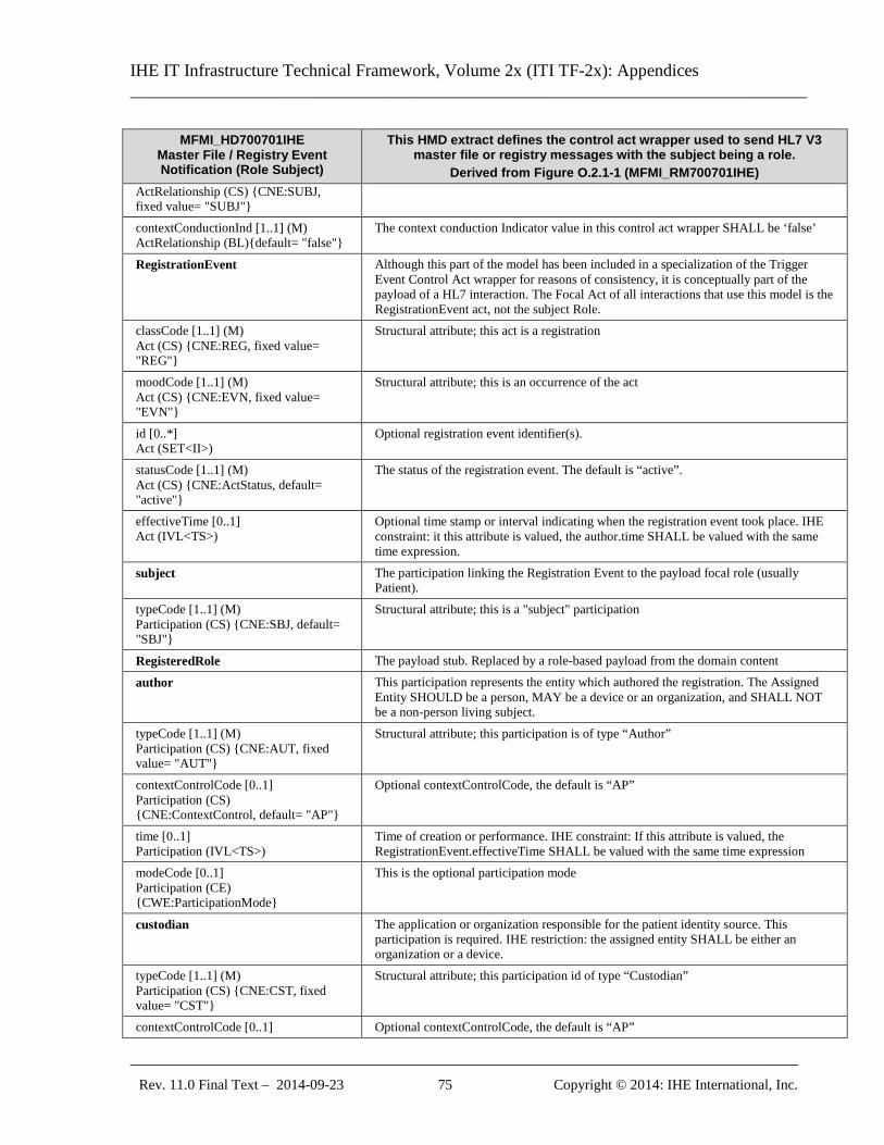
IHE IT Infrastructure Technical Framework, Volume 2x (ITI TF-2x): Appendices ______________________________________________________________________________
_____________________________________________________________________________ Rev. 11.0 Final Text – 2014-09-23 75 Copyright © 2014: IHE International, Inc.
MFMI_HD700701IHE Master File / Registry Event Notification (Role Subject)
This HMD extract defines the control act wrapper used to send HL7 V3 master file or registry messages with the subject being a role.
Derived from Figure O.2.1-1 (MFMI_RM700701IHE) ActRelationship (CS) {CNE:SUBJ, fixed value= "SUBJ"} contextConductionInd [1..1] (M) ActRelationship (BL){default= "false"}
The context conduction Indicator value in this control act wrapper SHALL be ‘false’
RegistrationEvent Although this part of the model has been included in a specialization of the Trigger Event Control Act wrapper for reasons of consistency, it is conceptually part of the payload of a HL7 interaction. The Focal Act of all interactions that use this model is the RegistrationEvent act, not the subject Role.
classCode [1..1] (M) Act (CS) {CNE:REG, fixed value= "REG"}
Structural attribute; this act is a registration
moodCode [1..1] (M) Act (CS) {CNE:EVN, fixed value= "EVN"}
Structural attribute; this is an occurrence of the act
id [0..*] Act (SET<II>)
Optional registration event identifier(s).
statusCode [1..1] (M) Act (CS) {CNE:ActStatus, default= "active"}
The status of the registration event. The default is “active”.
effectiveTime [0..1] Act (IVL<TS>)
Optional time stamp or interval indicating when the registration event took place. IHE constraint: it this attribute is valued, the author.time SHALL be valued with the same time expression.
subject The participation linking the Registration Event to the payload focal role (usually Patient).
typeCode [1..1] (M) Participation (CS) {CNE:SBJ, default= "SBJ"}
Structural attribute; this is a "subject" participation
RegisteredRole The payload stub. Replaced by a role-based payload from the domain content
author This participation represents the entity which authored the registration. The Assigned Entity SHOULD be a person, MAY be a device or an organization, and SHALL NOT be a non-person living subject.
typeCode [1..1] (M) Participation (CS) {CNE:AUT, fixed value= "AUT"}
Structural attribute; this participation is of type “Author”
contextControlCode [0..1] Participation (CS) {CNE:ContextControl, default= "AP"}
Optional contextControlCode, the default is “AP”
time [0..1] Participation (IVL<TS>)
Time of creation or performance. IHE constraint: If this attribute is valued, the RegistrationEvent.effectiveTime SHALL be valued with the same time expression
modeCode [0..1] Participation (CE) {CWE:ParticipationMode}
This is the optional participation mode
custodian The application or organization responsible for the patient identity source. This participation is required. IHE restriction: the assigned entity SHALL be either an organization or a device.
typeCode [1..1] (M) Participation (CS) {CNE:CST, fixed value= "CST"}
Structural attribute; this participation id of type “Custodian”
contextControlCode [0..1] Optional contextControlCode, the default is “AP”
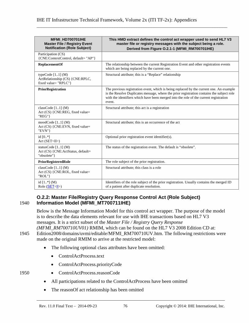
IHE IT Infrastructure Technical Framework, Volume 2x (ITI TF-2x): Appendices ______________________________________________________________________________
_____________________________________________________________________________ Rev. 11.0 Final Text – 2014-09-23 76 Copyright © 2014: IHE International, Inc.
MFMI_HD700701IHE Master File / Registry Event Notification (Role Subject)
This HMD extract defines the control act wrapper used to send HL7 V3 master file or registry messages with the subject being a role.
Derived from Figure O.2.1-1 (MFMI_RM700701IHE) Participation (CS) {CNE:ContextControl, default= "AP"}
ReplacementOf The relationship between the current Registration Event and other registration events which are being replaced by the current one.
typeCode [1..1] (M) ActRelationship (CS) {CNE:RPLC, fixed value= "RPLC"}
Structural attribute; this is a “Replace” relationship
PriorRegistration The previous registration event, which is being replaced by the current one. An example is the Resolve Duplicates message, where the prior registration contains the subject role with the identifiers which have been merged into the role of the current registration event.
classCode [1..1] (M) Act (CS) {CNE:REG, fixed value= "REG"}
Structural attribute; this act is a registration
moodCode [1..1] (M) Act (CS) {CNE:EVN, fixed value= "EVN"}
Structural attribute; this is an occurrence of the act
id [0..*] Act (SET<II>)
Optional prior registration event identifier(s).
statusCode [1..1] (M) Act (CS) {CNE:ActStatus, default= "obsolete"}
The status of the registration event. The default is “obsolete”.
PriorRegisteredRole The role subject of the prior registration. classCode [1..1] (M) Act (CS) {CNE:ROL, fixed value= "ROL"}
Structural attribute; this class is a role
id [1..*] (M) Role (SET<II>)
Identifiers of the role subject of the prior registration. Usually contains the merged ID of a patient after duplicate resolution.
O.2.2: Master File/Registry Query Response Control Act (Role Subject) Information Model (MFMI_MT700711IHE) 1940 Below is the Message Information Model for this control act wrapper. The purpose of the model is to describe the data elements relevant for use with IHE transactions based on HL7 V3 messages. It is a strict subset of the Master File / Registry Query Response (MFMI_RM700710UV01) RMIM, which can be found on the HL7 V3 2008 Edition CD at: Edition2008/domains/uvmi/editable/MFMI_RM700710UV.htm. The following restrictions were 1945 made on the original RMIM to arrive at the restricted model:
• The following optional class attributes have been omitted:
• ControlActProcess.text
• ControlActProcess.priorityCode
• ControlActProcess.reasonCode 1950
• All participations related to the ControlActProcess have been omitted
• The reasonOf act relationship has been omitted
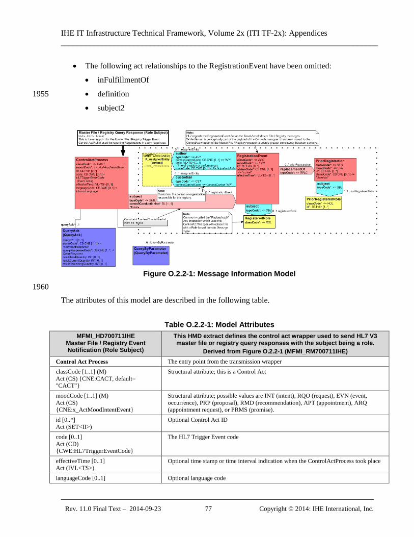
IHE IT Infrastructure Technical Framework, Volume 2x (ITI TF-2x): Appendices ______________________________________________________________________________
_____________________________________________________________________________ Rev. 11.0 Final Text – 2014-09-23 77 Copyright © 2014: IHE International, Inc.
• The following act relationships to the RegistrationEvent have been omitted:
• inFulfillmentOf
• definition 1955
• subject2
Figure O.2.2-1: Message Information Model
1960 The attributes of this model are described in the following table.
Table O.2.2-1: Model Attributes MFMI_HD700711IHE
Master File / Registry Event Notification (Role Subject)
This HMD extract defines the control act wrapper used to send HL7 V3 master file or registry query responses with the subject being a role.
Derived from Figure O.2.2-1 (MFMI_RM700711IHE) Control Act Process The entry point from the transmission wrapper classCode [1..1] (M) Act (CS) {CNE:CACT, default= "CACT"}
Structural attribute; this is a Control Act
moodCode [1..1] (M) Act (CS) {CNE:x_ActMoodIntentEvent}
Structural attribute; possible values are INT (intent), RQO (request), EVN (event, occurrence), PRP (proposal), RMD (recommendation), APT (appointment), ARQ (appointment request), or PRMS (promise).
id [0..*] Act (SET<II>)
Optional Control Act ID
code [0..1] Act (CD) {CWE:HL7TriggerEventCode}
The HL7 Trigger Event code
effectiveTime [0..1] Act (IVL<TS>)
Optional time stamp or time interval indication when the ControlActProcess took place
languageCode [0..1] Optional language code
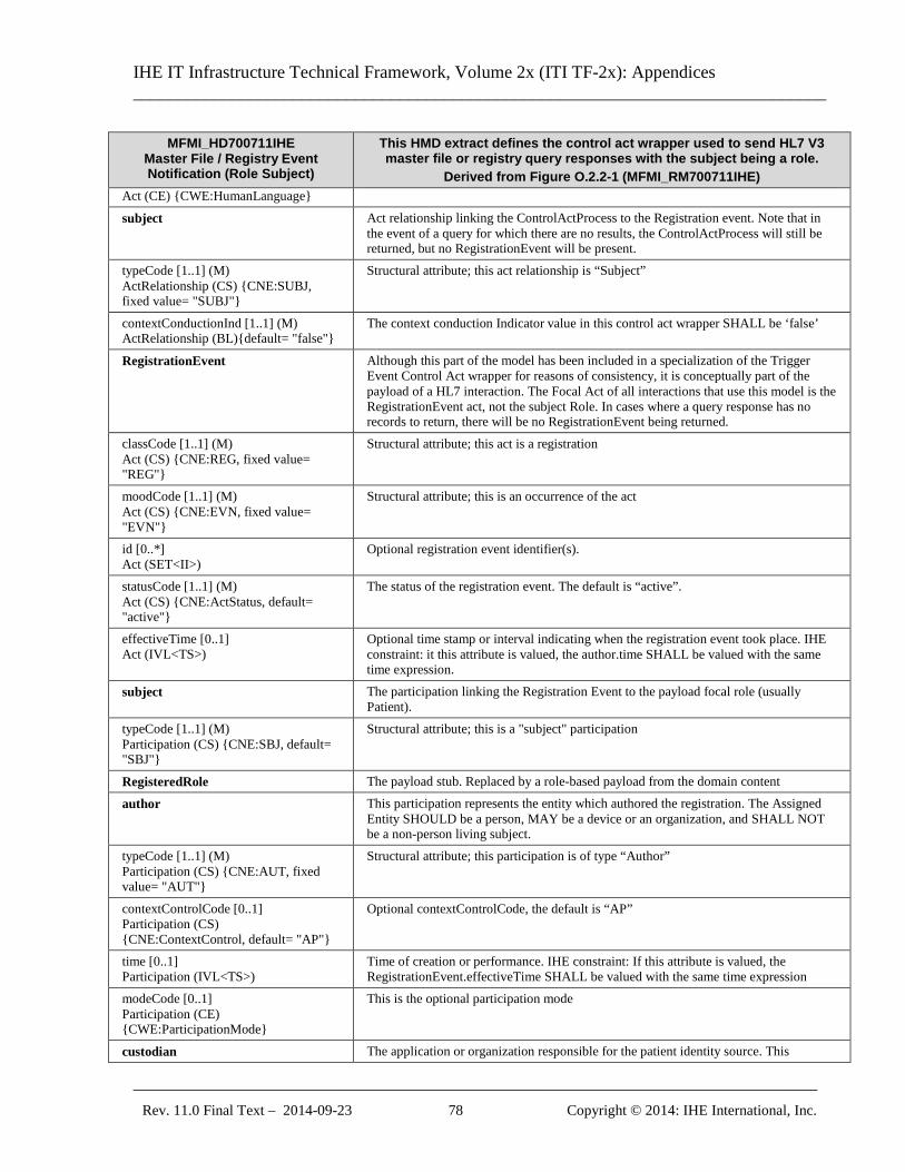
IHE IT Infrastructure Technical Framework, Volume 2x (ITI TF-2x): Appendices ______________________________________________________________________________
_____________________________________________________________________________ Rev. 11.0 Final Text – 2014-09-23 78 Copyright © 2014: IHE International, Inc.
MFMI_HD700711IHE Master File / Registry Event Notification (Role Subject)
This HMD extract defines the control act wrapper used to send HL7 V3 master file or registry query responses with the subject being a role.
Derived from Figure O.2.2-1 (MFMI_RM700711IHE) Act (CE) {CWE:HumanLanguage}
subject Act relationship linking the ControlActProcess to the Registration event. Note that in the event of a query for which there are no results, the ControlActProcess will still be returned, but no RegistrationEvent will be present.
typeCode [1..1] (M) ActRelationship (CS) {CNE:SUBJ, fixed value= "SUBJ"}
Structural attribute; this act relationship is “Subject”
contextConductionInd [1..1] (M) ActRelationship (BL){default= "false"}
The context conduction Indicator value in this control act wrapper SHALL be ‘false’
RegistrationEvent Although this part of the model has been included in a specialization of the Trigger Event Control Act wrapper for reasons of consistency, it is conceptually part of the payload of a HL7 interaction. The Focal Act of all interactions that use this model is the RegistrationEvent act, not the subject Role. In cases where a query response has no records to return, there will be no RegistrationEvent being returned.
classCode [1..1] (M) Act (CS) {CNE:REG, fixed value= "REG"}
Structural attribute; this act is a registration
moodCode [1..1] (M) Act (CS) {CNE:EVN, fixed value= "EVN"}
Structural attribute; this is an occurrence of the act
id [0..*] Act (SET<II>)
Optional registration event identifier(s).
statusCode [1..1] (M) Act (CS) {CNE:ActStatus, default= "active"}
The status of the registration event. The default is “active”.
effectiveTime [0..1] Act (IVL<TS>)
Optional time stamp or interval indicating when the registration event took place. IHE constraint: it this attribute is valued, the author.time SHALL be valued with the same time expression.
subject The participation linking the Registration Event to the payload focal role (usually Patient).
typeCode [1..1] (M) Participation (CS) {CNE:SBJ, default= "SBJ"}
Structural attribute; this is a "subject" participation
RegisteredRole The payload stub. Replaced by a role-based payload from the domain content
author This participation represents the entity which authored the registration. The Assigned Entity SHOULD be a person, MAY be a device or an organization, and SHALL NOT be a non-person living subject.
typeCode [1..1] (M) Participation (CS) {CNE:AUT, fixed value= "AUT"}
Structural attribute; this participation is of type “Author”
contextControlCode [0..1] Participation (CS) {CNE:ContextControl, default= "AP"}
Optional contextControlCode, the default is “AP”
time [0..1] Participation (IVL<TS>)
Time of creation or performance. IHE constraint: If this attribute is valued, the RegistrationEvent.effectiveTime SHALL be valued with the same time expression
modeCode [0..1] Participation (CE) {CWE:ParticipationMode}
This is the optional participation mode
custodian The application or organization responsible for the patient identity source. This
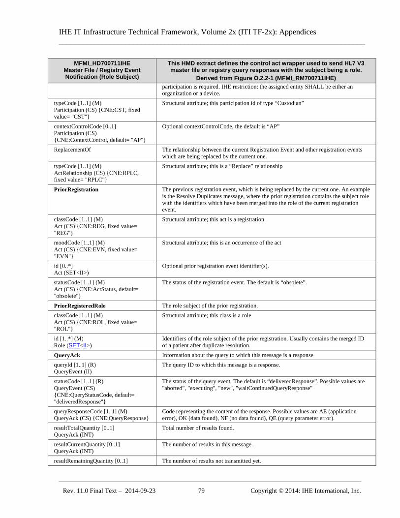
IHE IT Infrastructure Technical Framework, Volume 2x (ITI TF-2x): Appendices ______________________________________________________________________________
_____________________________________________________________________________ Rev. 11.0 Final Text – 2014-09-23 79 Copyright © 2014: IHE International, Inc.
MFMI_HD700711IHE Master File / Registry Event Notification (Role Subject)
This HMD extract defines the control act wrapper used to send HL7 V3 master file or registry query responses with the subject being a role.
Derived from Figure O.2.2-1 (MFMI_RM700711IHE) participation is required. IHE restriction: the assigned entity SHALL be either an organization or a device.
typeCode [1..1] (M) Participation (CS) {CNE:CST, fixed value= "CST"}
Structural attribute; this participation id of type “Custodian”
contextControlCode [0..1] Participation (CS) {CNE:ContextControl, default= "AP"}
Optional contextControlCode, the default is “AP”
ReplacementOf The relationship between the current Registration Event and other registration events which are being replaced by the current one.
typeCode [1..1] (M) ActRelationship (CS) {CNE:RPLC, fixed value= "RPLC"}
Structural attribute; this is a “Replace” relationship
PriorRegistration The previous registration event, which is being replaced by the current one. An example is the Resolve Duplicates message, where the prior registration contains the subject role with the identifiers which have been merged into the role of the current registration event.
classCode [1..1] (M) Act (CS) {CNE:REG, fixed value= "REG"}
Structural attribute; this act is a registration
moodCode [1..1] (M) Act (CS) {CNE:EVN, fixed value= "EVN"}
Structural attribute; this is an occurrence of the act
id [0..*] Act (SET<II>)
Optional prior registration event identifier(s).
statusCode [1..1] (M) Act (CS) {CNE:ActStatus, default= "obsolete"}
The status of the registration event. The default is “obsolete”.
PriorRegisteredRole The role subject of the prior registration. classCode [1..1] (M) Act (CS) {CNE:ROL, fixed value= "ROL"}
Structural attribute; this class is a role
id [1..*] (M) Role (SET<II>)
Identifiers of the role subject of the prior registration. Usually contains the merged ID of a patient after duplicate resolution.
QueryAck Information about the query to which this message is a response queryId [1..1] (R) QueryEvent (II)
The query ID to which this message is a response.
statusCode [1..1] (R) QueryEvent (CS) {CNE:QueryStatusCode, default= "deliveredResponse"}
The status of the query event. The default is “deliveredResponse”. Possible values are "aborted", "executing", "new", "waitContinuedQueryResponse"
queryResponseCode [1..1] (M) QueryAck (CS) {CNE:QueryResponse}
Code representing the content of the response. Possible values are AE (application error), OK (data found), NF (no data found), QE (query parameter error).
resultTotalQuantity [0..1] QueryAck (INT)
Total number of results found.
resultCurrentQuantity [0..1] QueryAck (INT)
The number of results in this message.
resultRemainingQuantity [0..1] The number of results not transmitted yet.
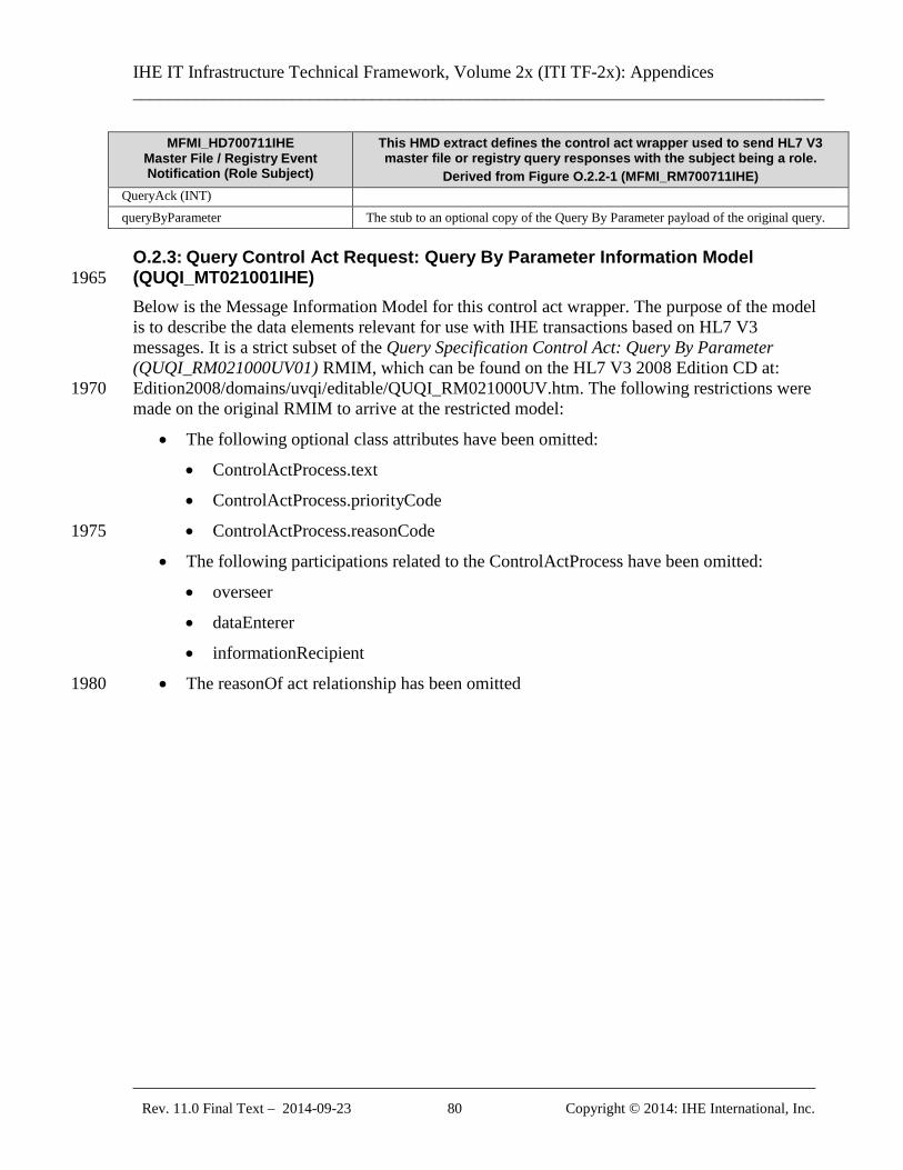
IHE IT Infrastructure Technical Framework, Volume 2x (ITI TF-2x): Appendices ______________________________________________________________________________
_____________________________________________________________________________ Rev. 11.0 Final Text – 2014-09-23 80 Copyright © 2014: IHE International, Inc.
MFMI_HD700711IHE Master File / Registry Event Notification (Role Subject)
This HMD extract defines the control act wrapper used to send HL7 V3 master file or registry query responses with the subject being a role.
Derived from Figure O.2.2-1 (MFMI_RM700711IHE) QueryAck (INT) queryByParameter The stub to an optional copy of the Query By Parameter payload of the original query.
O.2.3: Query Control Act Request: Query By Parameter Information Model (QUQI_MT021001IHE) 1965 Below is the Message Information Model for this control act wrapper. The purpose of the model is to describe the data elements relevant for use with IHE transactions based on HL7 V3 messages. It is a strict subset of the Query Specification Control Act: Query By Parameter (QUQI_RM021000UV01) RMIM, which can be found on the HL7 V3 2008 Edition CD at: Edition2008/domains/uvqi/editable/QUQI_RM021000UV.htm. The following restrictions were 1970 made on the original RMIM to arrive at the restricted model:
• The following optional class attributes have been omitted:
• ControlActProcess.text
• ControlActProcess.priorityCode
• ControlActProcess.reasonCode 1975
• The following participations related to the ControlActProcess have been omitted:
• overseer
• dataEnterer
• informationRecipient
• The reasonOf act relationship has been omitted 1980
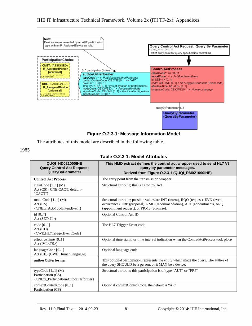
IHE IT Infrastructure Technical Framework, Volume 2x (ITI TF-2x): Appendices ______________________________________________________________________________
_____________________________________________________________________________ Rev. 11.0 Final Text – 2014-09-23 81 Copyright © 2014: IHE International, Inc.
Figure O.2.3-1: Message Information Model
The attributes of this model are described in the following table. 1985
Table O.2.3-1: Model Attributes QUQI_HD021000IHE
Query Control Act Request: QueryByParameter
This HMD extract defines the control act wrapper used to send HL7 V3 query by parameter messages.
Derived from Figure O.2.3-1 (QUQI_RM021000IHE) Control Act Process The entry point from the transmission wrapper classCode [1..1] (M) Act (CS) {CNE:CACT, default= "CACT"}
Structural attribute; this is a Control Act
moodCode [1..1] (M) Act (CS) {CNE:x_ActMoodIntentEvent}
Structural attribute; possible values are INT (intent), RQO (request), EVN (event, occurrence), PRP (proposal), RMD (recommendation), APT (appointment), ARQ (appointment request), or PRMS (promise).
id [0..*] Act (SET<II>)
Optional Control Act ID
code [0..1] Act (CD) {CWE:HL7TriggerEventCode}
The HL7 Trigger Event code
effectiveTime [0..1] Act (IVL<TS>)
Optional time stamp or time interval indication when the ControlActProcess took place
languageCode [0..1] Act (CE) {CWE:HumanLanguage}
Optional language code
authorOrPerformer This optional participation represents the entity which made the query. The author of the query SHOULD be a person, or it MAY be a device.
typeCode [1..1] (M) Participation (CS) {CNE:x_ParticipationAuthorPerformer}
Structural attribute; this participation is of type "AUT" or “PRF”
contextControlCode [0..1] Participation (CS)
Optional contextControlCode, the default is “AP”
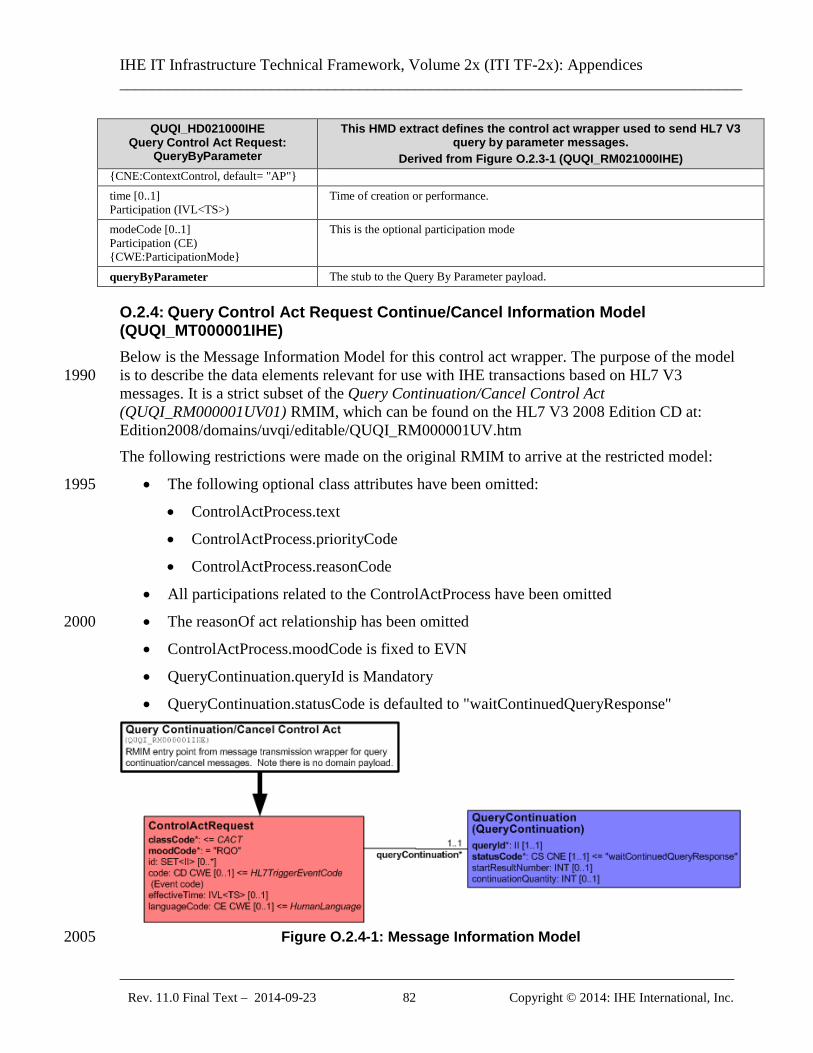
IHE IT Infrastructure Technical Framework, Volume 2x (ITI TF-2x): Appendices ______________________________________________________________________________
_____________________________________________________________________________ Rev. 11.0 Final Text – 2014-09-23 82 Copyright © 2014: IHE International, Inc.
QUQI_HD021000IHE Query Control Act Request:
QueryByParameter
This HMD extract defines the control act wrapper used to send HL7 V3 query by parameter messages.
Derived from Figure O.2.3-1 (QUQI_RM021000IHE) {CNE:ContextControl, default= "AP"} time [0..1] Participation (IVL<TS>)
Time of creation or performance.
modeCode [0..1] Participation (CE) {CWE:ParticipationMode}
This is the optional participation mode
queryByParameter The stub to the Query By Parameter payload.
O.2.4: Query Control Act Request Continue/Cancel Information Model (QUQI_MT000001IHE) Below is the Message Information Model for this control act wrapper. The purpose of the model is to describe the data elements relevant for use with IHE transactions based on HL7 V3 1990 messages. It is a strict subset of the Query Continuation/Cancel Control Act (QUQI_RM000001UV01) RMIM, which can be found on the HL7 V3 2008 Edition CD at: Edition2008/domains/uvqi/editable/QUQI_RM000001UV.htm The following restrictions were made on the original RMIM to arrive at the restricted model:
• The following optional class attributes have been omitted: 1995
• ControlActProcess.text
• ControlActProcess.priorityCode
• ControlActProcess.reasonCode
• All participations related to the ControlActProcess have been omitted
• The reasonOf act relationship has been omitted 2000
• ControlActProcess.moodCode is fixed to EVN
• QueryContinuation.queryId is Mandatory
• QueryContinuation.statusCode is defaulted to "waitContinuedQueryResponse"
Figure O.2.4-1: Message Information Model 2005
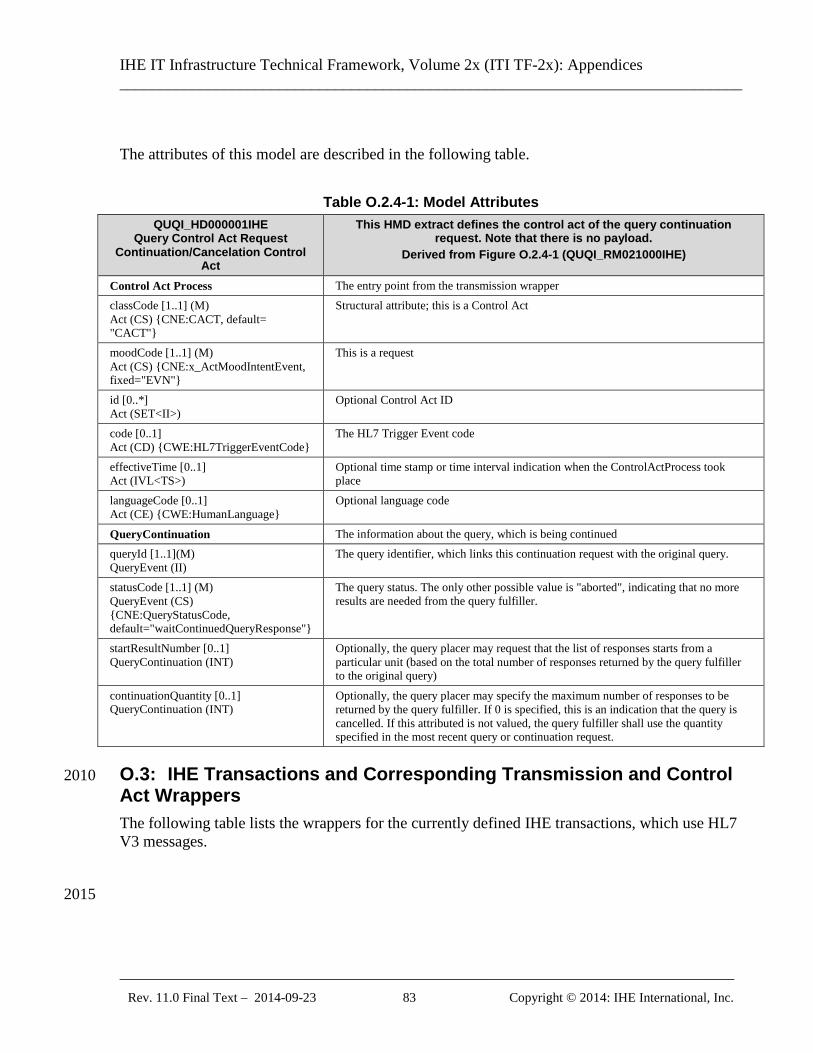
IHE IT Infrastructure Technical Framework, Volume 2x (ITI TF-2x): Appendices ______________________________________________________________________________
_____________________________________________________________________________ Rev. 11.0 Final Text – 2014-09-23 83 Copyright © 2014: IHE International, Inc.
The attributes of this model are described in the following table.
Table O.2.4-1: Model Attributes QUQI_HD000001IHE
Query Control Act Request Continuation/Cancelation Control
Act
This HMD extract defines the control act of the query continuation request. Note that there is no payload.
Derived from Figure O.2.4-1 (QUQI_RM021000IHE)
Control Act Process The entry point from the transmission wrapper classCode [1..1] (M) Act (CS) {CNE:CACT, default= "CACT"}
Structural attribute; this is a Control Act
moodCode [1..1] (M) Act (CS) {CNE:x_ActMoodIntentEvent, fixed="EVN"}
This is a request
id [0..*] Act (SET<II>)
Optional Control Act ID
code [0..1] Act (CD) {CWE:HL7TriggerEventCode}
The HL7 Trigger Event code
effectiveTime [0..1] Act (IVL<TS>)
Optional time stamp or time interval indication when the ControlActProcess took place
languageCode [0..1] Act (CE) {CWE:HumanLanguage}
Optional language code
QueryContinuation The information about the query, which is being continued queryId [1..1](M) QueryEvent (II)
The query identifier, which links this continuation request with the original query.
statusCode [1..1] (M) QueryEvent (CS) {CNE:QueryStatusCode, default="waitContinuedQueryResponse"}
The query status. The only other possible value is "aborted", indicating that no more results are needed from the query fulfiller.
startResultNumber [0..1] QueryContinuation (INT)
Optionally, the query placer may request that the list of responses starts from a particular unit (based on the total number of responses returned by the query fulfiller to the original query)
continuationQuantity [0..1] QueryContinuation (INT)
Optionally, the query placer may specify the maximum number of responses to be returned by the query fulfiller. If 0 is specified, this is an indication that the query is cancelled. If this attributed is not valued, the query fulfiller shall use the quantity specified in the most recent query or continuation request.
O.3: IHE Transactions and Corresponding Transmission and Control 2010 Act Wrappers The following table lists the wrappers for the currently defined IHE transactions, which use HL7 V3 messages. 2015
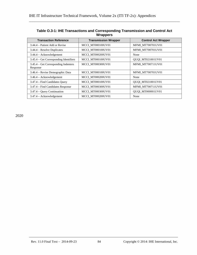
IHE IT Infrastructure Technical Framework, Volume 2x (ITI TF-2x): Appendices ______________________________________________________________________________
_____________________________________________________________________________ Rev. 11.0 Final Text – 2014-09-23 84 Copyright © 2014: IHE International, Inc.
Table O.3-1: IHE Transactions and Corresponding Transmission and Control Act Wrappers
Transaction Reference Transmission Wrapper Control Act Wrapper 3.44.4 – Patient Add or Revise MCCI_MT000100UV01 MFMI_MT700701UV01 3.44.4 – Resolve Duplicates MCCI_MT000100UV01 MFMI_MT700701UV01 3.44.4 – Acknowledgement MCCI_MT000200UV01 None 3.45.4 – Get Corresponding Identifiers MCCI_MT000100UV01 QUQI_MT021001UV01 3.45.4 – Get Corresponding Indenters Response
MCCI_MT000300UV01 MFMI_MT700711UV01
3.46.4 – Revise Demographic Data MCCI_MT000100UV01 MFMI_MT700701UV01 3.46.4 – Acknowledgement MCCI_MT000200UV01 None 3.47.4 – Find Candidates Query MCCI_MT000100UV01 QUQI_MT021001UV01 3.47.4 – Find Candidates Response MCCI_MT000300UV01 MFMI_MT700711UV01 3.47.4 – Query Continuation MCCI_MT000300UV01 QUQI_MT000001UV01 3.47.4 – Acknowledgement MCCI_MT000200UV01 None
2020
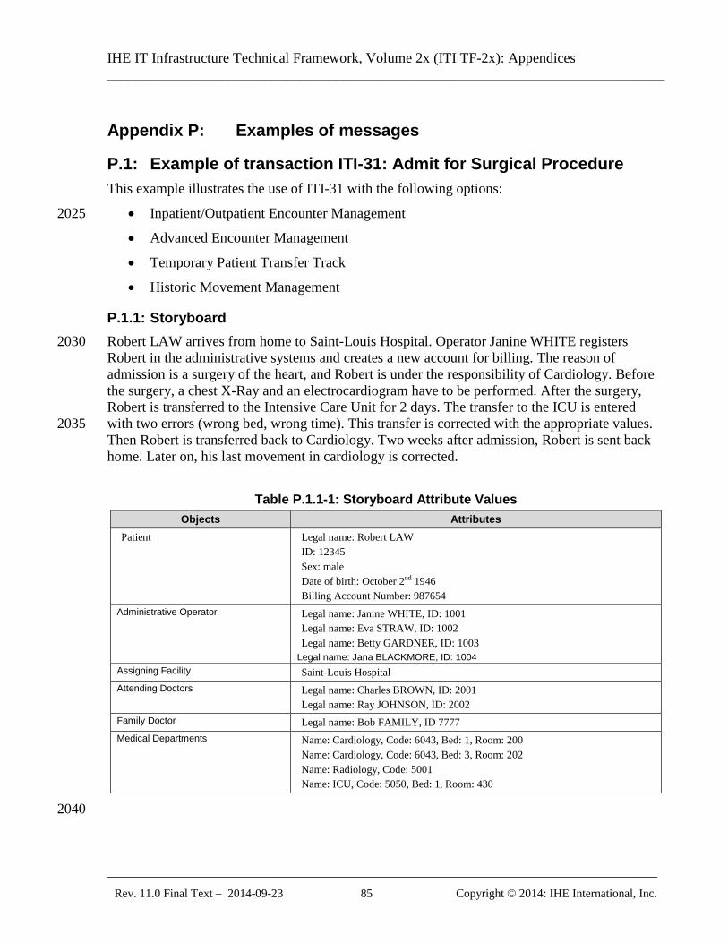
IHE IT Infrastructure Technical Framework, Volume 2x (ITI TF-2x): Appendices ______________________________________________________________________________
_____________________________________________________________________________ Rev. 11.0 Final Text – 2014-09-23 85 Copyright © 2014: IHE International, Inc.
Appendix P: Examples of messages
P.1: Example of transaction ITI-31: Admit for Surgical Procedure This example illustrates the use of ITI-31 with the following options:
• Inpatient/Outpatient Encounter Management 2025
• Advanced Encounter Management
• Temporary Patient Transfer Track
• Historic Movement Management
P.1.1: Storyboard Robert LAW arrives from home to Saint-Louis Hospital. Operator Janine WHITE registers 2030 Robert in the administrative systems and creates a new account for billing. The reason of admission is a surgery of the heart, and Robert is under the responsibility of Cardiology. Before the surgery, a chest X-Ray and an electrocardiogram have to be performed. After the surgery, Robert is transferred to the Intensive Care Unit for 2 days. The transfer to the ICU is entered with two errors (wrong bed, wrong time). This transfer is corrected with the appropriate values. 2035 Then Robert is transferred back to Cardiology. Two weeks after admission, Robert is sent back home. Later on, his last movement in cardiology is corrected.
Table P.1.1-1: Storyboard Attribute Values Objects Attributes
Patient Legal name: Robert LAW ID: 12345 Sex: male Date of birth: October 2nd 1946 Billing Account Number: 987654
Administrative Operator Legal name: Janine WHITE, ID: 1001 Legal name: Eva STRAW, ID: 1002 Legal name: Betty GARDNER, ID: 1003
Legal name: Jana BLACKMORE, ID: 1004 Assigning Facility Saint-Louis Hospital Attending Doctors Legal name: Charles BROWN, ID: 2001
Legal name: Ray JOHNSON, ID: 2002 Family Doctor Legal name: Bob FAMILY, ID 7777 Medical Departments Name: Cardiology, Code: 6043, Bed: 1, Room: 200
Name: Cardiology, Code: 6043, Bed: 3, Room: 202 Name: Radiology, Code: 5001 Name: ICU, Code: 5050, Bed: 1, Room: 430
2040
IHE IT Infrastructure Technical Framework, Volume 2x (ITI TF-2x): Appendices ______________________________________________________________________________
_____________________________________________________________________________ Rev. 11.0 Final Text – 2014-09-23 86 Copyright © 2014: IHE International, Inc.
P.1.2: Interaction Diagram The following diagram illustrates the interactions used in this Example. The acknowledgement messages are not shown.
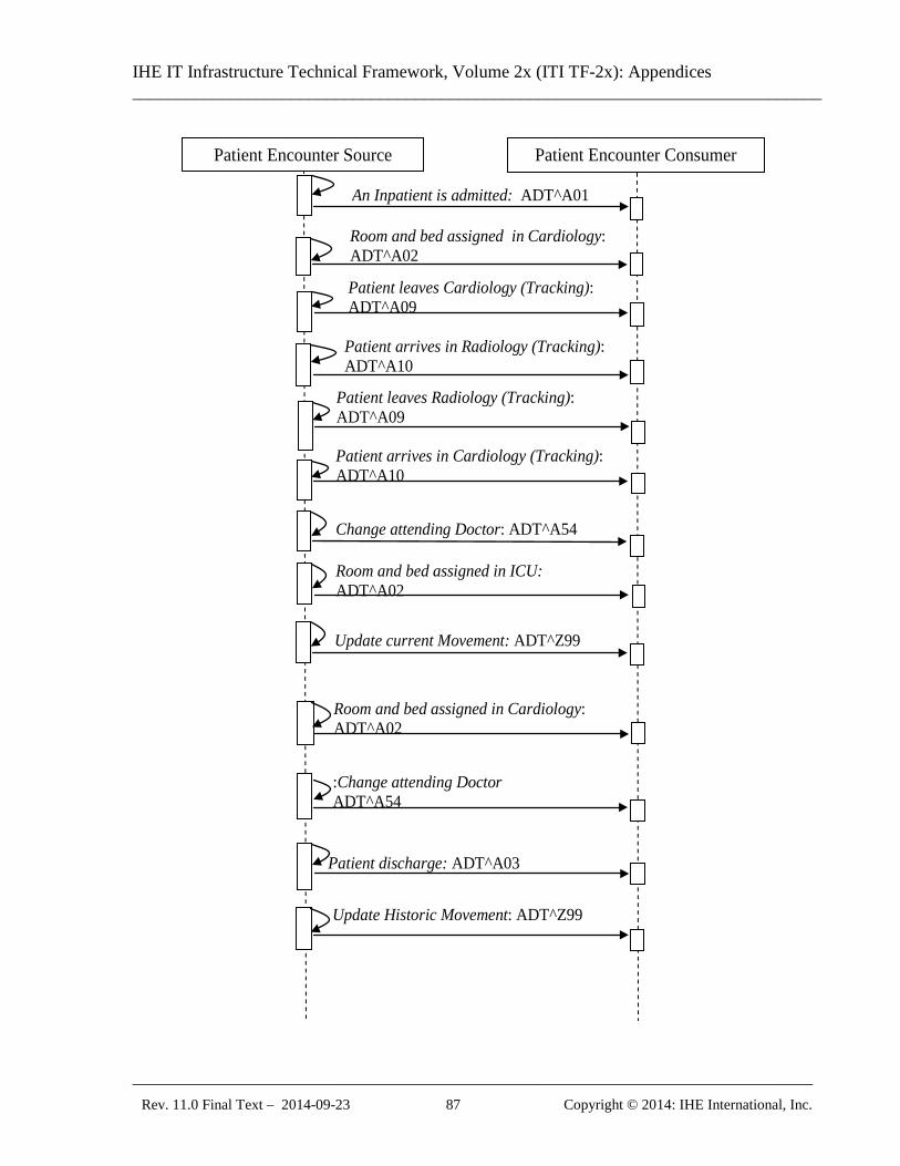
IHE IT Infrastructure Technical Framework, Volume 2x (ITI TF-2x): Appendices ______________________________________________________________________________
_____________________________________________________________________________ Rev. 11.0 Final Text – 2014-09-23 87 Copyright © 2014: IHE International, Inc.
An Inpatient is admitted: ADT^A01 Room and bed assigned in Cardiology: ADT^A02
Patient arrives in Radiology (Tracking): ADT^A10
Patient arrives in Cardiology (Tracking): ADT^A10
Change attending Doctor: ADT^A54 Room and bed assigned in ICU: ADT^A02
Room and bed assigned in Cardiology: ADT^A02
:Change attending Doctor ADT^A54
Patient discharge: ADT^A03
Patient leaves Cardiology (Tracking): ADT^A09
Patient leaves Radiology (Tracking): ADT^A09
Patient Encounter Consumer Patient Encounter Source
Update Historic Movement: ADT^Z99
Update current Movement: ADT^Z99
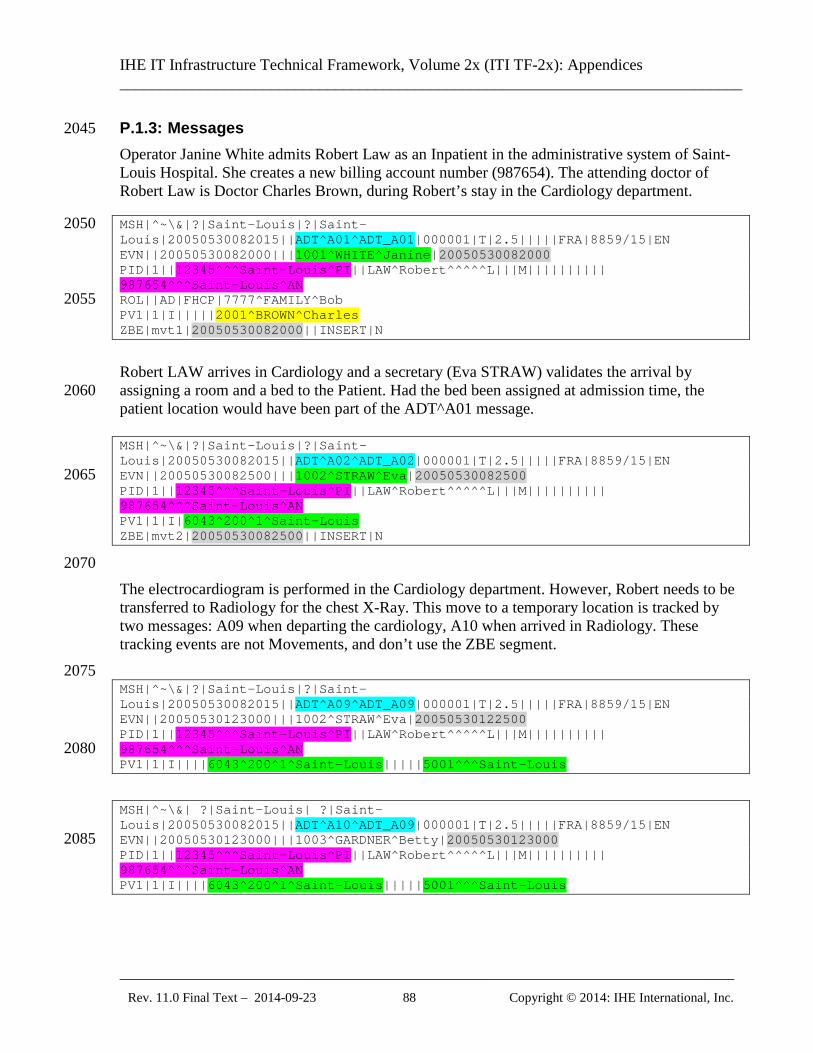
IHE IT Infrastructure Technical Framework, Volume 2x (ITI TF-2x): Appendices ______________________________________________________________________________
_____________________________________________________________________________ Rev. 11.0 Final Text – 2014-09-23 88 Copyright © 2014: IHE International, Inc.
P.1.3: Messages 2045 Operator Janine White admits Robert Law as an Inpatient in the administrative system of Saint-Louis Hospital. She creates a new billing account number (987654). The attending doctor of Robert Law is Doctor Charles Brown, during Robert’s stay in the Cardiology department. MSH|^~\&|?|Saint-Louis|?|Saint-2050 Louis|20050530082015||ADT^A01^ADT_A01|000001|T|2.5|||||FRA|8859/15|EN EVN||20050530082000|||1001^WHITE^Janine|20050530082000 PID|1||12345^^^Saint-Louis^PI||LAW^Robert^^^^^L|||M|||||||||| 987654^^^Saint-Louis^AN ROL||AD|FHCP|7777^FAMILY^Bob 2055 PV1|1|I|||||2001^BROWN^Charles ZBE|mvt1|20050530082000||INSERT|N
Robert LAW arrives in Cardiology and a secretary (Eva STRAW) validates the arrival by assigning a room and a bed to the Patient. Had the bed been assigned at admission time, the 2060 patient location would have been part of the ADT^A01 message. MSH|^~\&|?|Saint-Louis|?|Saint-Louis|20050530082015||ADT^A02^ADT_A02|000001|T|2.5|||||FRA|8859/15|EN EVN||20050530082500|||1002^STRAW^Eva|20050530082500 2065 PID|1||12345^^^Saint-Louis^PI||LAW^Robert^^^^^L|||M|||||||||| 987654^^^Saint-Louis^AN PV1|1|I|6043^200^1^Saint-Louis ZBE|mvt2|20050530082500||INSERT|N
2070 The electrocardiogram is performed in the Cardiology department. However, Robert needs to be transferred to Radiology for the chest X-Ray. This move to a temporary location is tracked by two messages: A09 when departing the cardiology, A10 when arrived in Radiology. These tracking events are not Movements, and don’t use the ZBE segment. 2075 MSH|^~\&|?|Saint-Louis|?|Saint-Louis|20050530082015||ADT^A09^ADT_A09|000001|T|2.5|||||FRA|8859/15|EN EVN||20050530123000|||1002^STRAW^Eva|20050530122500 PID|1||12345^^^Saint-Louis^PI||LAW^Robert^^^^^L|||M|||||||||| 987654^^^Saint-Louis^AN 2080 PV1|1|I||||6043^200^1^Saint-Louis|||||5001^^^Saint-Louis
MSH|^~\&| ?|Saint-Louis| ?|Saint-Louis|20050530082015||ADT^A10^ADT_A09|000001|T|2.5|||||FRA|8859/15|EN EVN||20050530123000|||1003^GARDNER^Betty|20050530123000 2085 PID|1||12345^^^Saint-Louis^PI||LAW^Robert^^^^^L|||M|||||||||| 987654^^^Saint-Louis^AN PV1|1|I||||6043^200^1^Saint-Louis|||||5001^^^Saint-Louis
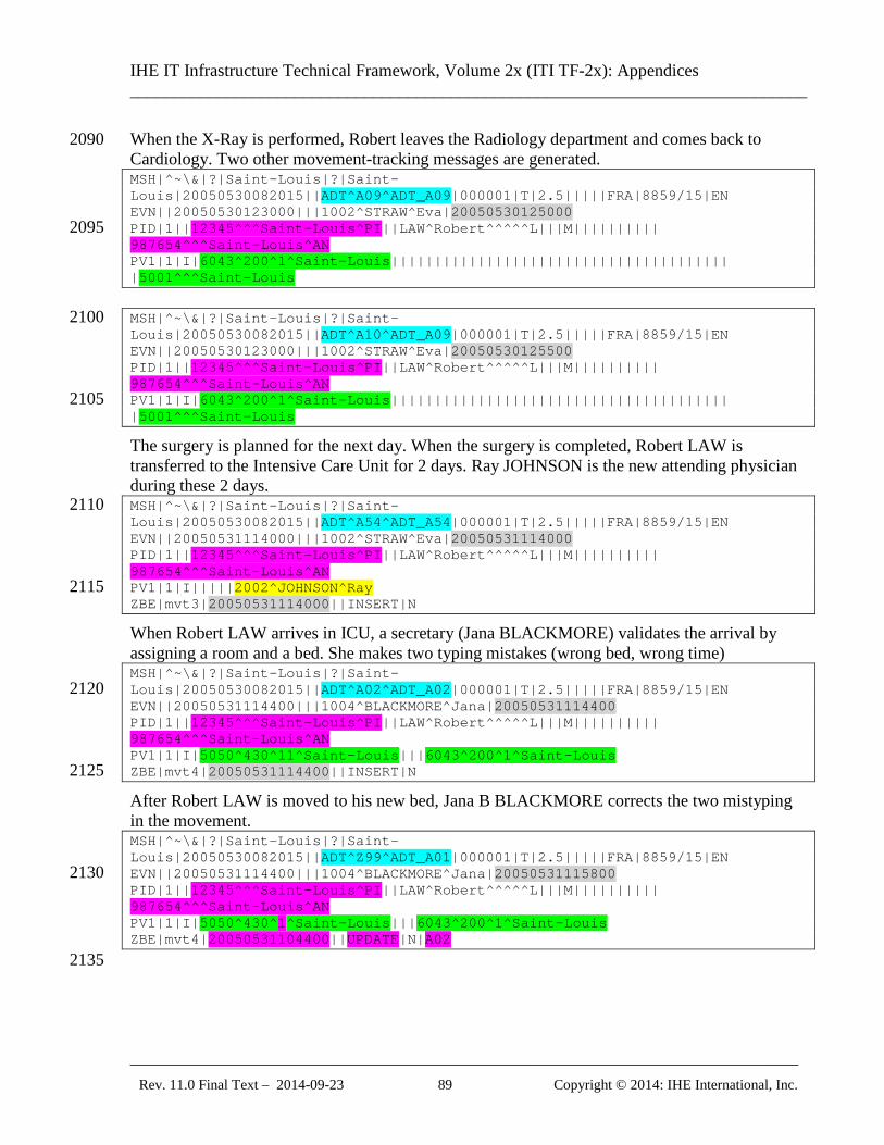
IHE IT Infrastructure Technical Framework, Volume 2x (ITI TF-2x): Appendices ______________________________________________________________________________
_____________________________________________________________________________ Rev. 11.0 Final Text – 2014-09-23 89 Copyright © 2014: IHE International, Inc.
When the X-Ray is performed, Robert leaves the Radiology department and comes back to 2090 Cardiology. Two other movement-tracking messages are generated. MSH|^~\&|?|Saint-Louis|?|Saint-Louis|20050530082015||ADT^A09^ADT_A09|000001|T|2.5|||||FRA|8859/15|EN EVN||20050530123000|||1002^STRAW^Eva|20050530125000 PID|1||12345^^^Saint-Louis^PI||LAW^Robert^^^^^L|||M|||||||||| 2095 987654^^^Saint-Louis^AN PV1|1|I|6043^200^1^Saint-Louis||||||||||||||||||||||||||||||||||||||| |5001^^^Saint-Louis
MSH|^~\&|?|Saint-Louis|?|Saint-2100 Louis|20050530082015||ADT^A10^ADT_A09|000001|T|2.5|||||FRA|8859/15|EN EVN||20050530123000|||1002^STRAW^Eva|20050530125500 PID|1||12345^^^Saint-Louis^PI||LAW^Robert^^^^^L|||M|||||||||| 987654^^^Saint-Louis^AN PV1|1|I|6043^200^1^Saint-Louis||||||||||||||||||||||||||||||||||||||| 2105 |5001^^^Saint-Louis
The surgery is planned for the next day. When the surgery is completed, Robert LAW is transferred to the Intensive Care Unit for 2 days. Ray JOHNSON is the new attending physician during these 2 days. MSH|^~\&|?|Saint-Louis|?|Saint-2110 Louis|20050530082015||ADT^A54^ADT_A54|000001|T|2.5|||||FRA|8859/15|EN EVN||20050531114000|||1002^STRAW^Eva|20050531114000 PID|1||12345^^^Saint-Louis^PI||LAW^Robert^^^^^L|||M|||||||||| 987654^^^Saint-Louis^AN PV1|1|I|||||2002^JOHNSON^Ray 2115 ZBE|mvt3|20050531114000||INSERT|N
When Robert LAW arrives in ICU, a secretary (Jana BLACKMORE) validates the arrival by assigning a room and a bed. She makes two typing mistakes (wrong bed, wrong time) MSH|^~\&|?|Saint-Louis|?|Saint-Louis|20050530082015||ADT^A02^ADT_A02|000001|T|2.5|||||FRA|8859/15|EN 2120 EVN||20050531114400|||1004^BLACKMORE^Jana|20050531114400 PID|1||12345^^^Saint-Louis^PI||LAW^Robert^^^^^L|||M|||||||||| 987654^^^Saint-Louis^AN PV1|1|I|5050^430^11^Saint-Louis|||6043^200^1^Saint-Louis ZBE|mvt4|20050531114400||INSERT|N 2125
After Robert LAW is moved to his new bed, Jana B BLACKMORE corrects the two mistyping in the movement. MSH|^~\&|?|Saint-Louis|?|Saint-Louis|20050530082015||ADT^Z99^ADT_A01|000001|T|2.5|||||FRA|8859/15|EN EVN||20050531114400|||1004^BLACKMORE^Jana|20050531115800 2130 PID|1||12345^^^Saint-Louis^PI||LAW^Robert^^^^^L|||M|||||||||| 987654^^^Saint-Louis^AN PV1|1|I|5050^430^1^Saint-Louis|||6043^200^1^Saint-Louis ZBE|mvt4|20050531104400||UPDATE|N|A02
2135
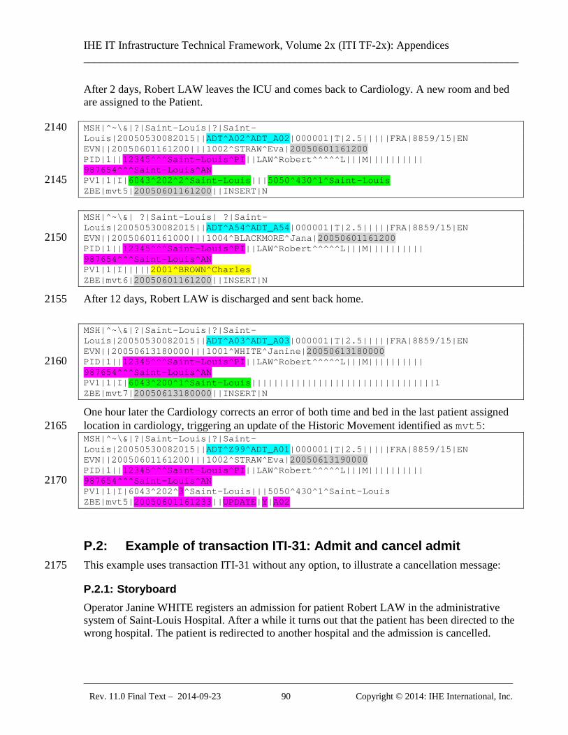
IHE IT Infrastructure Technical Framework, Volume 2x (ITI TF-2x): Appendices ______________________________________________________________________________
_____________________________________________________________________________ Rev. 11.0 Final Text – 2014-09-23 90 Copyright © 2014: IHE International, Inc.
After 2 days, Robert LAW leaves the ICU and comes back to Cardiology. A new room and bed are assigned to the Patient. MSH|^~\&|?|Saint-Louis|?|Saint-2140 Louis|20050530082015||ADT^A02^ADT_A02|000001|T|2.5|||||FRA|8859/15|EN EVN||20050601161200|||1002^STRAW^Eva|20050601161200 PID|1||12345^^^Saint-Louis^PI||LAW^Robert^^^^^L|||M|||||||||| 987654^^^Saint-Louis^AN PV1|1|I|6043^202^2^Saint-Louis|||5050^430^1^Saint-Louis 2145 ZBE|mvt5|20050601161200||INSERT|N
MSH|^~\&| ?|Saint-Louis| ?|Saint-Louis|20050530082015||ADT^A54^ADT_A54|000001|T|2.5|||||FRA|8859/15|EN EVN||20050601161000|||1004^BLACKMORE^Jana|20050601161200 2150 PID|1||12345^^^Saint-Louis^PI||LAW^Robert^^^^^L|||M|||||||||| 987654^^^Saint-Louis^AN PV1|1|I|||||2001^BROWN^Charles ZBE|mvt6|20050601161200||INSERT|N
After 12 days, Robert LAW is discharged and sent back home. 2155 MSH|^~\&|?|Saint-Louis|?|Saint-Louis|20050530082015||ADT^A03^ADT_A03|000001|T|2.5|||||FRA|8859/15|EN EVN||20050613180000|||1001^WHITE^Janine|20050613180000 PID|1||12345^^^Saint-Louis^PI||LAW^Robert^^^^^L|||M|||||||||| 2160 987654^^^Saint-Louis^AN PV1|1|I|6043^200^1^Saint-Louis|||||||||||||||||||||||||||||||||1 ZBE|mvt7|20050613180000||INSERT|N
One hour later the Cardiology corrects an error of both time and bed in the last patient assigned location in cardiology, triggering an update of the Historic Movement identified as mvt5: 2165 MSH|^~\&|?|Saint-Louis|?|Saint-Louis|20050530082015||ADT^Z99^ADT_A01|000001|T|2.5|||||FRA|8859/15|EN EVN||20050601161200|||1002^STRAW^Eva|20050613190000 PID|1||12345^^^Saint-Louis^PI||LAW^Robert^^^^^L|||M|||||||||| 987654^^^Saint-Louis^AN 2170 PV1|1|I|6043^202^3^Saint-Louis|||5050^430^1^Saint-Louis ZBE|mvt5|20050601161233||UPDATE|Y|A02
P.2: Example of transaction ITI-31: Admit and cancel admit This example uses transaction ITI-31 without any option, to illustrate a cancellation message: 2175
P.2.1: Storyboard Operator Janine WHITE registers an admission for patient Robert LAW in the administrative system of Saint-Louis Hospital. After a while it turns out that the patient has been directed to the wrong hospital. The patient is redirected to another hospital and the admission is cancelled.
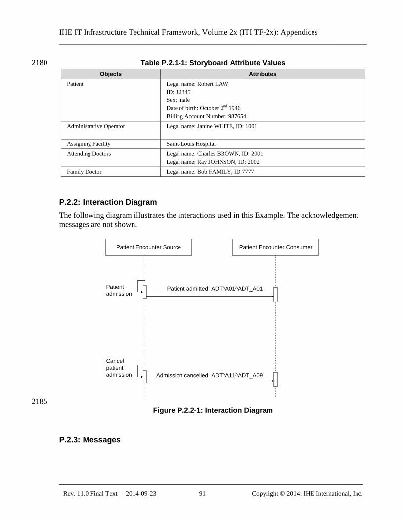
IHE IT Infrastructure Technical Framework, Volume 2x (ITI TF-2x): Appendices ______________________________________________________________________________
_____________________________________________________________________________ Rev. 11.0 Final Text – 2014-09-23 91 Copyright © 2014: IHE International, Inc.
Table P.2.1-1: Storyboard Attribute Values 2180 Objects Attributes
Patient Legal name: Robert LAW ID: 12345 Sex: male Date of birth: October 2nd 1946 Billing Account Number: 987654
Administrative Operator Legal name: Janine WHITE, ID: 1001
Assigning Facility Saint-Louis Hospital Attending Doctors Legal name: Charles BROWN, ID: 2001
Legal name: Ray JOHNSON, ID: 2002 Family Doctor Legal name: Bob FAMILY, ID 7777
P.2.2: Interaction Diagram The following diagram illustrates the interactions used in this Example. The acknowledgement messages are not shown.
Patient Encounter Source Patient Encounter Consumer
Patient admission
Cancel patient admission
Patient admitted: ADT^A01^ADT_A01
Admission cancelled: ADT^A11^ADT_A09
2185 Figure P.2.2-1: Interaction Diagram
P.2.3: Messages
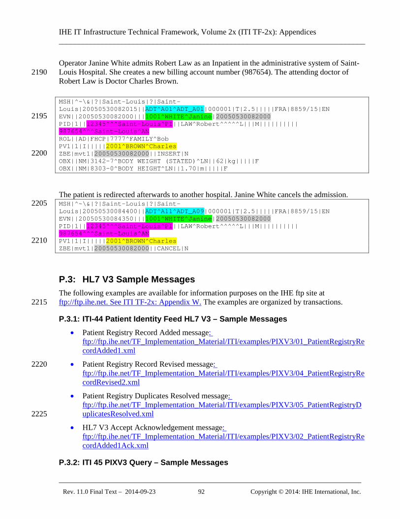
IHE IT Infrastructure Technical Framework, Volume 2x (ITI TF-2x): Appendices ______________________________________________________________________________
_____________________________________________________________________________ Rev. 11.0 Final Text – 2014-09-23 92 Copyright © 2014: IHE International, Inc.
Operator Janine White admits Robert Law as an Inpatient in the administrative system of Saint-Louis Hospital. She creates a new billing account number (987654). The attending doctor of 2190 Robert Law is Doctor Charles Brown. MSH|^~\&|?|Saint-Louis|?|Saint-Louis|20050530082015||ADT^A01^ADT_A01|000001|T|2.5|||||FRA|8859/15|EN EVN||20050530082000|||1001^WHITE^Janine|20050530082000 2195 PID|1||12345^^^Saint-Louis^PI||LAW^Robert^^^^^L|||M|||||||||| 987654^^^Saint-Louis^AN ROL||AD|FHCP|7777^FAMILY^Bob PV1|1|I|||||2001^BROWN^Charles ZBE|mvt1|20050530082000||INSERT|N 2200 OBX||NM|3142-7^BODY WEIGHT (STATED)^LN||62|kg|||||F OBX||NM|8303-0^BODY HEIGHT^LN||1.70|m|||||F
The patient is redirected afterwards to another hospital. Janine White cancels the admission. MSH|^~\&|?|Saint-Louis|?|Saint-2205 Louis|20050530084400||ADT^A11^ADT_A09|000001|T|2.5|||||FRA|8859/15|EN EVN||20050530084350|||1001^WHITE^Janine|20050530082000 PID|1||12345^^^Saint-Louis^PI||LAW^Robert^^^^^L|||M|||||||||| 987654^^^Saint-Louis^AN PV1|1|I|||||2001^BROWN^Charles 2210 ZBE|mvt1|20050530082000||CANCEL|N
P.3: HL7 V3 Sample Messages The following examples are available for information purposes on the IHE ftp site at ftp://ftp.ihe.net. See ITI TF-2x: Appendix W. The examples are organized by transactions. 2215
P.3.1: ITI-44 Patient Identity Feed HL7 V3 – Sample Messages • Patient Registry Record Added message:
ftp://ftp.ihe.net/TF_Implementation_Material/ITI/examples/PIXV3/01_PatientRegistryRecordAdded1.xml
• Patient Registry Record Revised message: 2220 ftp://ftp.ihe.net/TF_Implementation_Material/ITI/examples/PIXV3/04_PatientRegistryRecordRevised2.xml
• Patient Registry Duplicates Resolved message: ftp://ftp.ihe.net/TF_Implementation_Material/ITI/examples/PIXV3/05_PatientRegistryDuplicatesResolved.xml 2225
• HL7 V3 Accept Acknowledgement message: ftp://ftp.ihe.net/TF_Implementation_Material/ITI/examples/PIXV3/02_PatientRegistryRecordAdded1Ack.xml
P.3.2: ITI 45 PIXV3 Query – Sample Messages
IHE IT Infrastructure Technical Framework, Volume 2x (ITI TF-2x): Appendices ______________________________________________________________________________
_____________________________________________________________________________ Rev. 11.0 Final Text – 2014-09-23 93 Copyright © 2014: IHE International, Inc.
• Patient Registry Get Identifiers Query message: 2230 ftp://ftp.ihe.net/TF_Implementation_Material/ITI/examples/PIXV3/06_PIXQuery1.xml
• Patient Registry Get Identifiers Query Response message: ftp://ftp.ihe.net/TF_Implementation_Material/ITI/examples/PIXV3/07_PIXQuery1Response.xml
P.3.3: ITI 46 PIXV3 Update Notification – Sample Messages 2235
• Patient Registry Record Revised message: ftp://ftp.ihe.net/TF_Implementation_Material/ITI/examples/PIXV3/04_PatientRegistryRecordRevised2.xml
• HL7 V3 Accept Acknowledgement message: ftp://ftp.ihe.net/TF_Implementation_Material/ITI/examples/PIXV3/02_PatientRegistryRe2240 cordAdded1Ack.xml
P.3.4: ITI 47 Patient Demographics Query HL7 V3 – Sample Messages • Patient Registry Find Candidates Query message:
ftp://ftp.ihe.net/TF_Implementation_Material/ITI/examples/PDQV3/01_PDQQuery1.xml
• Patient Registry Find Candidates Query Response message: 2245 ftp://ftp.ihe.net/TF_Implementation_Material/ITI/examples/PDQV3/02_PDQQuery1Response.xml
• General Query Activate Query Continue message: ftp://ftp.ihe.net/TF_Implementation_Material/ITI/examples/PDQV3/03_PDQQuery1Continuation.xml 2250
• General Query Activate Query Continue Response message: ftp://ftp.ihe.net/TF_Implementation_Material/ITI/examples/PDQV3/04_PDQQuery1ContinuationResponse.xml
• General Query Activate Query Cancel message: ftp://ftp.ihe.net/TF_Implementation_Material/ITI/examples/PDQV3/05_PDQQuery1Can2255 cel.xml
• General Query Activate Query Cancel Acknowledgment message: ftp://ftp.ihe.net/TF_Implementation_Material/ITI/examples/PDQV3/06_PDQQuery1CancelAck.xml
2260
IHE IT Infrastructure Technical Framework, Volume 2x (ITI TF-2x): Appendices ______________________________________________________________________________
_____________________________________________________________________________ Rev. 11.0 Final Text – 2014-09-23 94 Copyright © 2014: IHE International, Inc.
Appendix Q: HL7 V3 Sample Payload XML Schemas The following examples are available for information purposes on the IHE ftp site at ftp://ftp.ihe.net. See ITI TF-2x: Appendix W. The examples are organized by transactions.
Q.1: ITI-44 Patient Identity Feed HL7 V3 – Sample Schemas • Patient Registry Record Added schema: 2265
ftp://ftp.ihe.net/TF_Implementation_Material/ITI/schema/HL7V3/NE2008/multicacheschemas/PRPA_IN201301UV02.xsd
• Patient Registry Record Revised schema: ftp://ftp.ihe.net/TF_Implementation_Material/ITI/schema/HL7V3/NE2008/multicacheschemas/PRPA_IN201302UV02.xsd 2270
• Patient Registry Duplicates Resolved schema: ftp://ftp.ihe.net/TF_Implementation_Material/ITI/schema/HL7V3/NE2008/multicacheschemas/PRPA_IN201304UV02.xsd
• HL7 V3 Accept Acknowledgment schema: ftp://ftp.ihe.net/TF_Implementation_Material/ITI/schema/HL7V3/NE2008/multicachesch2275 emas/MCCI_IN000002UV01.xsd
Q.2: ITI-45 PIXV3 Query – Sample Schemas • Patient Registry Get Identifiers Query schema:
ftp://ftp.ihe.net/TF_Implementation_Material/ITI/schema/HL7V3/NE2008/multicacheschemas/PRPA_IN201309UV02.xsd 2280
• Patient Registry Get Identifiers Query Response schema: ftp://ftp.ihe.net/TF_Implementation_Material/ITI/schema/HL7V3/NE2008/multicacheschemas/PRPA_IN201310UV02.xsd
Q.3: ITI-46 PIXV3 Update Notification – Sample Schemas • Patient Registry Record Revised schema: 2285
ftp://ftp.ihe.net/TF_Implementation_Material/ITI/schema/HL7V3/NE2008/multicacheschemas/PRPA_IN201302UV02.xsd
• HL7 V3 Accept Acknowledgment schema: ftp://ftp.ihe.net/TF_Implementation_Material/ITI/schema/HL7V3/NE2008/multicacheschemas/MCCI_IN000002UV01.xsd 2290
Q.4: ITI-47 Patient Demographics Query HL7 V3 – Sample Schemas • Patient Registry Find Candidates Query schema:
ftp://ftp.ihe.net/TF_Implementation_Material/ITI/schema/HL7V3/NE2008/multicacheschemas/PRPA_IN201305UV02.xsd
IHE IT Infrastructure Technical Framework, Volume 2x (ITI TF-2x): Appendices ______________________________________________________________________________
_____________________________________________________________________________ Rev. 11.0 Final Text – 2014-09-23 95 Copyright © 2014: IHE International, Inc.
• Patient Registry Find Candidates Query Response schema: 2295 ftp://ftp.ihe.net/TF_Implementation_Material/ITI/schema/HL7V3/NE2008/multicacheschemas/PRPA_IN201306UV02.xsd
• General Query Activate Query Continue schema: ftp://ftp.ihe.net/TF_Implementation_Material/ITI/schema/HL7V3/NE2008/multicacheschemas/QUQI_IN000003UV01.xsd 2300
• HL7 V3 Accept Acknowledgment schema:
• ftp://ftp.ihe.net/TF_Implementation_Material/ITI/schema/HL7V3/NE2008/multicacheschemas/MCCI_IN000002UV01.xsd
2305
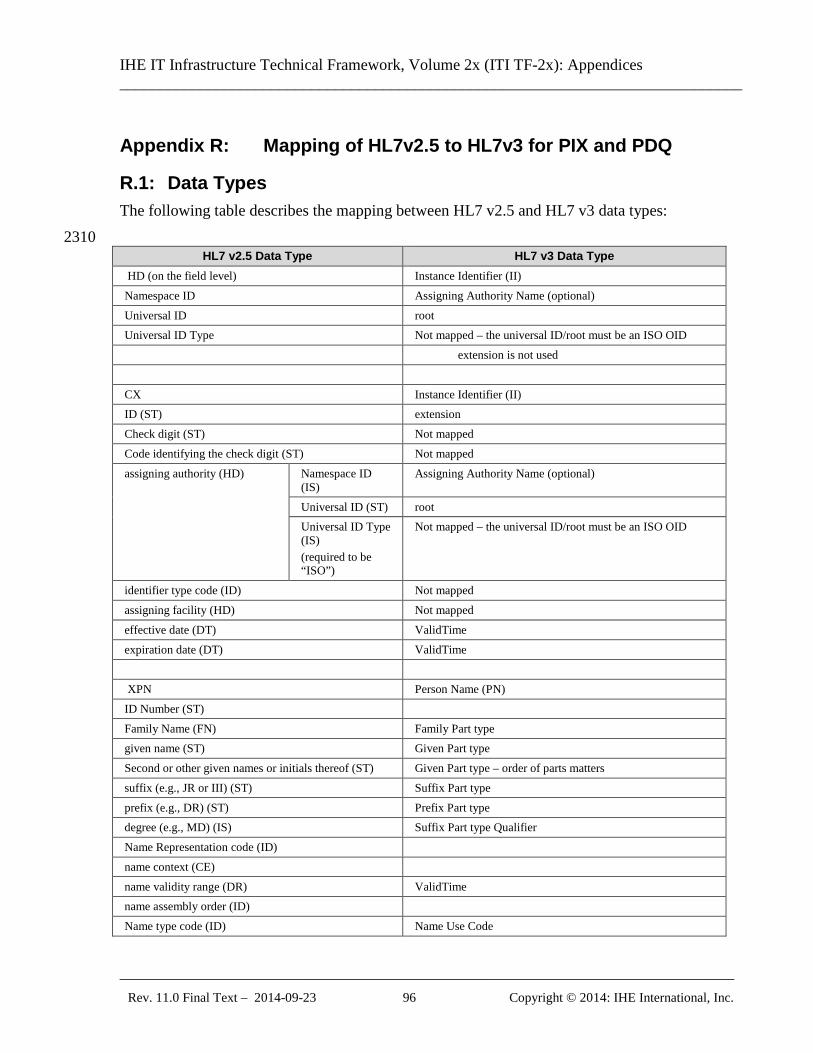
IHE IT Infrastructure Technical Framework, Volume 2x (ITI TF-2x): Appendices ______________________________________________________________________________
_____________________________________________________________________________ Rev. 11.0 Final Text – 2014-09-23 96 Copyright © 2014: IHE International, Inc.
Appendix R: Mapping of HL7v2.5 to HL7v3 for PIX and PDQ
R.1: Data Types The following table describes the mapping between HL7 v2.5 and HL7 v3 data types: 2310
HL7 v2.5 Data Type HL7 v3 Data Type HD (on the field level) Instance Identifier (II) Namespace ID Assigning Authority Name (optional) Universal ID root Universal ID Type Not mapped – the universal ID/root must be an ISO OID extension is not used CX Instance Identifier (II) ID (ST) extension Check digit (ST) Not mapped Code identifying the check digit (ST) Not mapped assigning authority (HD) Namespace ID
(IS) Assigning Authority Name (optional)
Universal ID (ST) root Universal ID Type (IS) (required to be “ISO”)
Not mapped – the universal ID/root must be an ISO OID
identifier type code (ID) Not mapped assigning facility (HD) Not mapped effective date (DT) ValidTime expiration date (DT) ValidTime XPN Person Name (PN) ID Number (ST) Family Name (FN) Family Part type given name (ST) Given Part type Second or other given names or initials thereof (ST) Given Part type – order of parts matters suffix (e.g., JR or III) (ST) Suffix Part type prefix (e.g., DR) (ST) Prefix Part type degree (e.g., MD) (IS) Suffix Part type Qualifier Name Representation code (ID) name context (CE) name validity range (DR) ValidTime name assembly order (ID) Name type code (ID) Name Use Code
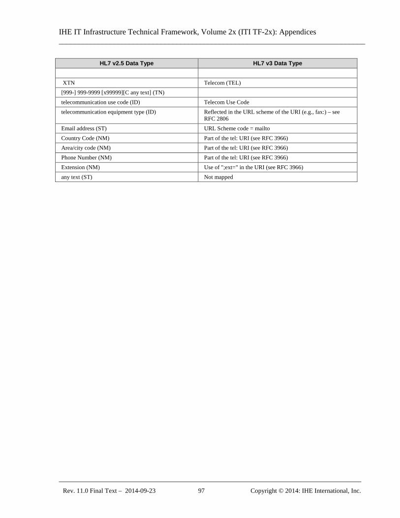
IHE IT Infrastructure Technical Framework, Volume 2x (ITI TF-2x): Appendices ______________________________________________________________________________
_____________________________________________________________________________ Rev. 11.0 Final Text – 2014-09-23 97 Copyright © 2014: IHE International, Inc.
HL7 v2.5 Data Type HL7 v3 Data Type XTN Telecom (TEL) [999-] 999-9999 [x99999][C any text] (TN) telecommunication use code (ID) Telecom Use Code telecommunication equipment type (ID) Reflected in the URL scheme of the URI (e.g., fax:) – see
RFC 2806 Email address (ST) URL Scheme code = mailto Country Code (NM) Part of the tel: URI (see RFC 3966) Area/city code (NM) Part of the tel: URI (see RFC 3966) Phone Number (NM) Part of the tel: URI (see RFC 3966) Extension (NM) Use of ";ext=" in the URI (see RFC 3966) any text (ST) Not mapped
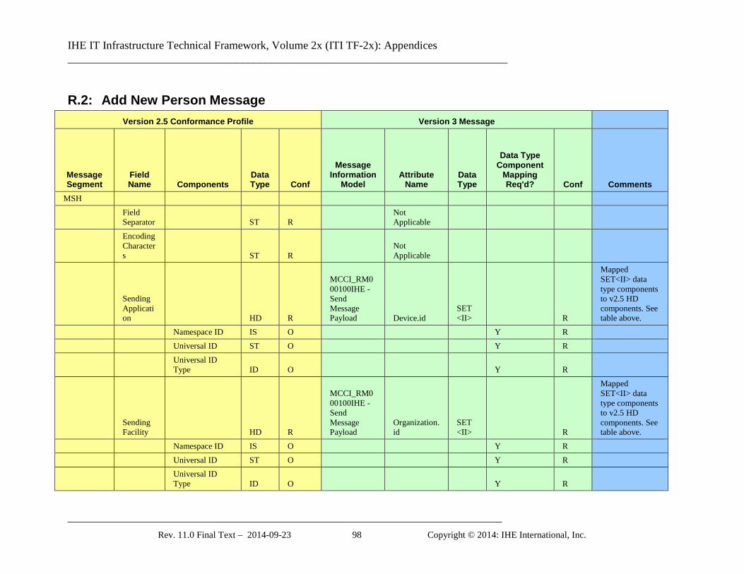
IHE IT Infrastructure Technical Framework, Volume 2x (ITI TF-2x): Appendices ______________________________________________________________________________
_____________________________________________________________________________ Rev. 11.0 Final Text – 2014-09-23 98 Copyright © 2014: IHE International, Inc.
R.2: Add New Person Message Version 2.5 Conformance Profile Version 3 Message
Message Segment
Field Name Components
Data Type Conf
Message Information
Model Attribute
Name Data Type
Data Type Component
Mapping Req'd? Conf Comments
MSH
Field Separator ST R
Not Applicable
Encoding Characters ST R
Not Applicable
Sending Application HD R
MCCI_RM000100IHE - Send Message Payload Device.id
SET <II> R
Mapped SET<II> data type components to v2.5 HD components. See table above.
Namespace ID IS O Y R Universal ID ST O Y R
Universal ID Type ID O Y R
Sending Facility HD R
MCCI_RM000100IHE - Send Message Payload
Organization.id
SET <II> R
Mapped SET<II> data type components to v2.5 HD components. See table above.
Namespace ID IS O Y R Universal ID ST O Y R
Universal ID Type ID O Y R
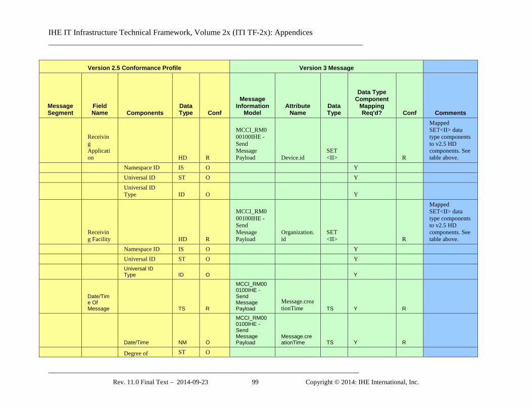
IHE IT Infrastructure Technical Framework, Volume 2x (ITI TF-2x): Appendices ______________________________________________________________________________
_____________________________________________________________________________ Rev. 11.0 Final Text – 2014-09-23 99 Copyright © 2014: IHE International, Inc.
Version 2.5 Conformance Profile Version 3 Message
Message Segment
Field Name Components
Data Type Conf
Message Information
Model Attribute
Name Data Type
Data Type Component
Mapping Req'd? Conf Comments
Receiving Application HD R
MCCI_RM000100IHE - Send Message Payload Device.id
SET <II> R
Mapped SET<II> data type components to v2.5 HD components. See table above.
Namespace ID IS O Y Universal ID ST O Y
Universal ID Type ID O Y
Receiving Facility HD R
MCCI_RM000100IHE - Send Message Payload
Organization.id
SET <II> R
Mapped SET<II> data type components to v2.5 HD components. See table above.
Namespace ID IS O Y Universal ID ST O Y
Universal ID Type ID O Y
Date/Time Of Message TS R
MCCI_RM000100IHE - Send Message Payload
Message.creationTime TS Y R
Date/Time NM O
MCCI_RM000100IHE - Send Message Payload
Message.creationTime TS Y R
Degree of ST O
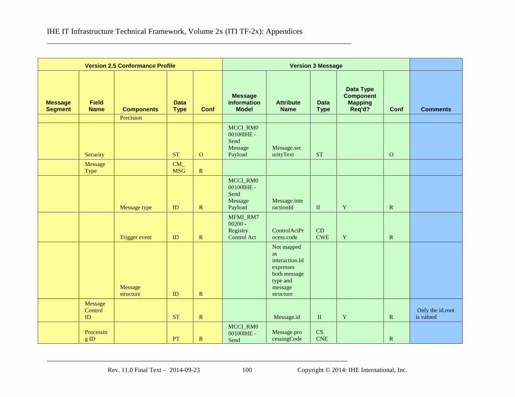
IHE IT Infrastructure Technical Framework, Volume 2x (ITI TF-2x): Appendices ______________________________________________________________________________
_____________________________________________________________________________ Rev. 11.0 Final Text – 2014-09-23 100 Copyright © 2014: IHE International, Inc.
Version 2.5 Conformance Profile Version 3 Message
Message Segment
Field Name Components
Data Type Conf
Message Information
Model Attribute
Name Data Type
Data Type Component
Mapping Req'd? Conf Comments
Precision
Security ST O
MCCI_RM000100IHE - Send Message Payload
Message.securityText ST O
Message Type
CM_MSG R
Message type ID R
MCCI_RM000100IHE - Send Message Payload
Message.interactionId II Y R
Trigger event ID R
MFMI_RM700200 - Registry Control Act
ControlActProcess.code
CD CWE Y R
Message structure ID R
Not mapped as interaction.Id expresses both message type and message structure
Message Control ID ST R Message.id II Y R
Only the id.root is valued
Processing ID PT R
MCCI_RM000100IHE - Send
Message.processingCode
CS CNE R
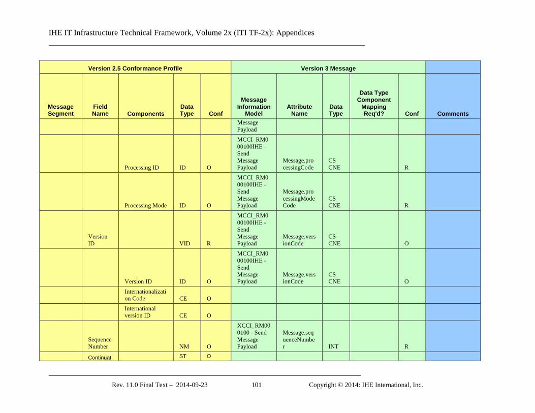
IHE IT Infrastructure Technical Framework, Volume 2x (ITI TF-2x): Appendices ______________________________________________________________________________
_____________________________________________________________________________ Rev. 11.0 Final Text – 2014-09-23 101 Copyright © 2014: IHE International, Inc.
Version 2.5 Conformance Profile Version 3 Message
Message Segment
Field Name Components
Data Type Conf
Message Information
Model Attribute
Name Data Type
Data Type Component
Mapping Req'd? Conf Comments
Message Payload
Processing ID ID O
MCCI_RM000100IHE - Send Message Payload
Message.processingCode
CS CNE R
Processing Mode ID O
MCCI_RM000100IHE - Send Message Payload
Message.processingModeCode
CS CNE R
Version ID VID R
MCCI_RM000100IHE - Send Message Payload
Message.versionCode
CS CNE O
Version ID ID O
MCCI_RM000100IHE - Send Message Payload
Message.versionCode
CS CNE O
Internationalization Code CE O
International version ID CE O
Sequence Number NM O
XCCI_RM000100 - Send Message Payload
Message.sequenceNumber INT R
Continuat ST O
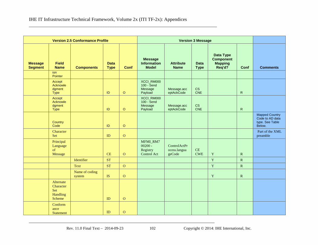
IHE IT Infrastructure Technical Framework, Volume 2x (ITI TF-2x): Appendices ______________________________________________________________________________
_____________________________________________________________________________ Rev. 11.0 Final Text – 2014-09-23 102 Copyright © 2014: IHE International, Inc.
Version 2.5 Conformance Profile Version 3 Message
Message Segment
Field Name Components
Data Type Conf
Message Information
Model Attribute
Name Data Type
Data Type Component
Mapping Req'd? Conf Comments
ion Pointer
Accept Acknowledgment Type ID O
XCCI_RM000100 - Send Message Payload
Message.acceptAckCode
CS CNE R
Accept Acknowledgment Type ID O
XCCI_RM000100 - Send Message Payload
Message.acceptAckCode
CS CNE R
Country Code ID O
Mapped Country Code to AD data type. See Table Below.
Character Set ID O
Part of the XML preamble
Principal Language of Message CE O
MFMI_RM700200 - Registry Control Act
ControlActProcess.languageCode
CE CWE Y R
Identifier ST Y R Text ST O Y R
Name of coding system IS O Y R
Alternate Character Set Handling Scheme ID O
Conformance Statement ID O
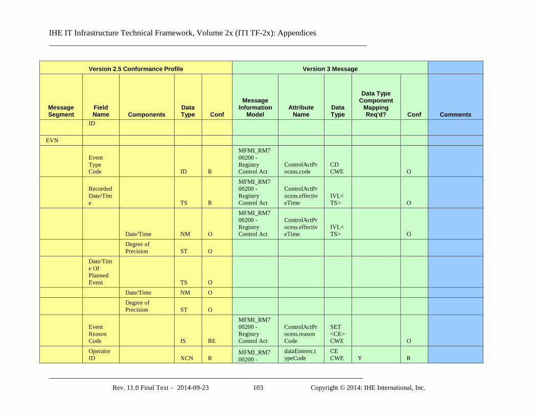
IHE IT Infrastructure Technical Framework, Volume 2x (ITI TF-2x): Appendices ______________________________________________________________________________
_____________________________________________________________________________ Rev. 11.0 Final Text – 2014-09-23 103 Copyright © 2014: IHE International, Inc.
Version 2.5 Conformance Profile Version 3 Message
Message Segment
Field Name Components
Data Type Conf
Message Information
Model Attribute
Name Data Type
Data Type Component
Mapping Req'd? Conf Comments
ID
EVN
Event Type Code ID R
MFMI_RM700200 - Registry Control Act
ControlActProcess.code
CD CWE O
Recorded Date/Time TS R
MFMI_RM700200 - Registry Control Act
ControlActProcess.effectiveTime
IVL<TS> O
Date/Time NM O
MFMI_RM700200 - Registry Control Act
ControlActProcess.effectiveTime
IVL<TS> O
Degree of Precision ST O
Date/Time Of Planned Event TS O
Date/Time NM O
Degree of Precision ST O
Event Reason Code IS RE
MFMI_RM700200 - Registry Control Act
ControlActProcess.reasonCode
SET <CE> CWE O
Operator ID XCN R
MFMI_RM700200 -
dataEnterer.typeCode
CE CWE Y R
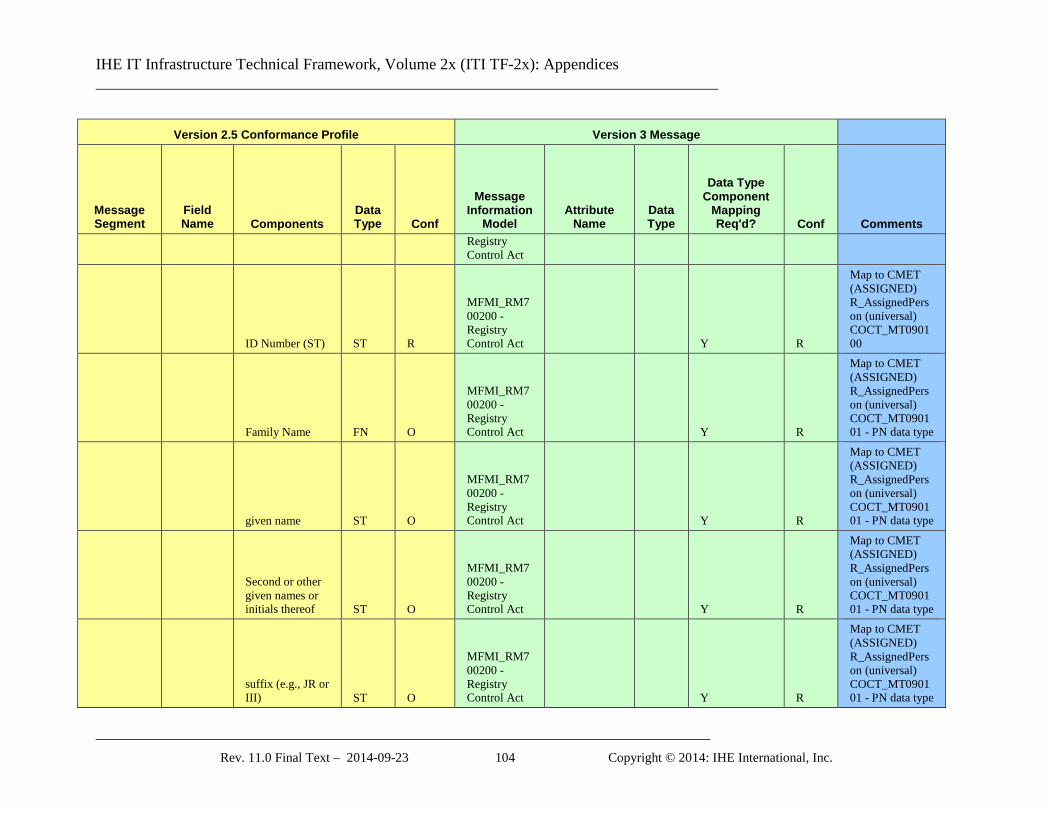
IHE IT Infrastructure Technical Framework, Volume 2x (ITI TF-2x): Appendices ______________________________________________________________________________
_____________________________________________________________________________ Rev. 11.0 Final Text – 2014-09-23 104 Copyright © 2014: IHE International, Inc.
Version 2.5 Conformance Profile Version 3 Message
Message Segment
Field Name Components
Data Type Conf
Message Information
Model Attribute
Name Data Type
Data Type Component
Mapping Req'd? Conf Comments
Registry Control Act
ID Number (ST) ST R
MFMI_RM700200 - Registry Control Act Y R
Map to CMET (ASSIGNED) R_AssignedPerson (universal) COCT_MT090100
Family Name FN O
MFMI_RM700200 - Registry Control Act Y R
Map to CMET (ASSIGNED) R_AssignedPerson (universal) COCT_MT090101 - PN data type
given name ST O
MFMI_RM700200 - Registry Control Act Y R
Map to CMET (ASSIGNED) R_AssignedPerson (universal) COCT_MT090101 - PN data type
Second or other given names or initials thereof ST O
MFMI_RM700200 - Registry Control Act Y R
Map to CMET (ASSIGNED) R_AssignedPerson (universal) COCT_MT090101 - PN data type
suffix (e.g., JR or III) ST O
MFMI_RM700200 - Registry Control Act Y R
Map to CMET (ASSIGNED) R_AssignedPerson (universal) COCT_MT090101 - PN data type
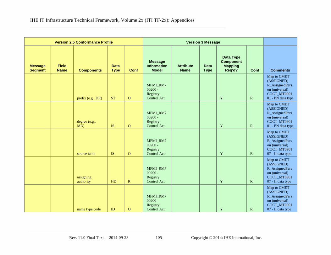
IHE IT Infrastructure Technical Framework, Volume 2x (ITI TF-2x): Appendices ______________________________________________________________________________
_____________________________________________________________________________ Rev. 11.0 Final Text – 2014-09-23 105 Copyright © 2014: IHE International, Inc.
Version 2.5 Conformance Profile Version 3 Message
Message Segment
Field Name Components
Data Type Conf
Message Information
Model Attribute
Name Data Type
Data Type Component
Mapping Req'd? Conf Comments
prefix (e.g., DR) ST O
MFMI_RM700200 - Registry Control Act Y R
Map to CMET (ASSIGNED) R_AssignedPerson (universal) COCT_MT090101 - PN data type
degree (e.g., MD) IS O
MFMI_RM700200 - Registry Control Act Y R
Map to CMET (ASSIGNED) R_AssignedPerson (universal) COCT_MT090101 - PN data type
source table IS O
MFMI_RM700200 - Registry Control Act Y R
Map to CMET (ASSIGNED) R_AssignedPerson (universal) COCT_MT090107 - II data type
assigning authority HD R
MFMI_RM700200 - Registry Control Act Y R
Map to CMET (ASSIGNED) R_AssignedPerson (universal) COCT_MT090107 - II data type
name type code ID O
MFMI_RM700200 - Registry Control Act Y R
Map to CMET (ASSIGNED) R_AssignedPerson (universal) COCT_MT090107 - II data type
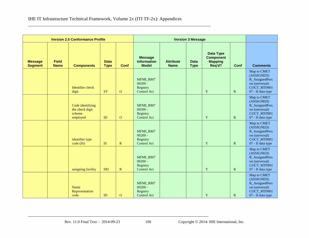
IHE IT Infrastructure Technical Framework, Volume 2x (ITI TF-2x): Appendices ______________________________________________________________________________
_____________________________________________________________________________ Rev. 11.0 Final Text – 2014-09-23 106 Copyright © 2014: IHE International, Inc.
Version 2.5 Conformance Profile Version 3 Message
Message Segment
Field Name Components
Data Type Conf
Message Information
Model Attribute
Name Data Type
Data Type Component
Mapping Req'd? Conf Comments
Identifier check digit ST O
MFMI_RM700200 - Registry Control Act Y R
Map to CMET (ASSIGNED) R_AssignedPerson (universal) COCT_MT090107 - II data type
Code identifying the check digit scheme employed ID O
MFMI_RM700200 - Registry Control Act Y R
Map to CMET (ASSIGNED) R_AssignedPerson (universal) COCT_MT090107 - II data type
identifier type code (IS) IS R
MFMI_RM700200 - Registry Control Act Y R
Map to CMET (ASSIGNED) R_AssignedPerson (universal) COCT_MT090107 - II data type
assigning facility HD R
MFMI_RM700200 - Registry Control Act Y R
Map to CMET (ASSIGNED) R_AssignedPerson (universal) COCT_MT090107 - II data type
Name Representation code ID O
MFMI_RM700200 - Registry Control Act Y R
Map to CMET (ASSIGNED) R_AssignedPerson (universal) COCT_MT090107 - II data type
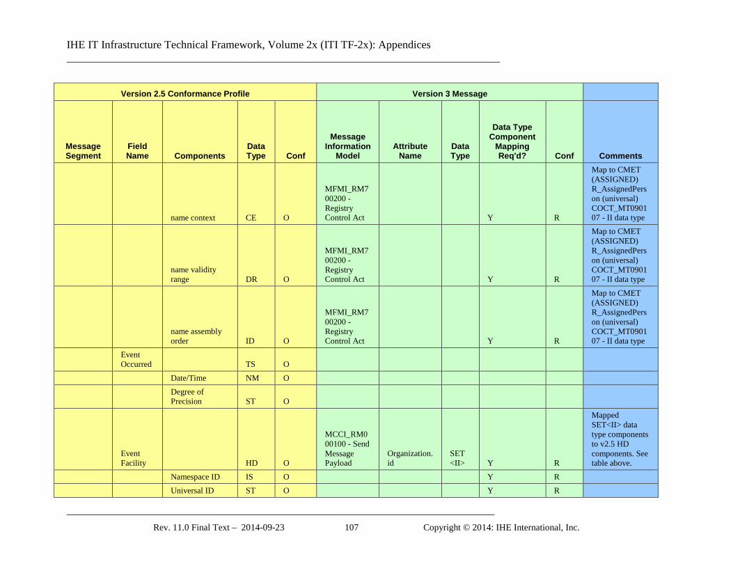
IHE IT Infrastructure Technical Framework, Volume 2x (ITI TF-2x): Appendices ______________________________________________________________________________
_____________________________________________________________________________ Rev. 11.0 Final Text – 2014-09-23 107 Copyright © 2014: IHE International, Inc.
Version 2.5 Conformance Profile Version 3 Message
Message Segment
Field Name Components
Data Type Conf
Message Information
Model Attribute
Name Data Type
Data Type Component
Mapping Req'd? Conf Comments
name context CE O
MFMI_RM700200 - Registry Control Act Y R
Map to CMET (ASSIGNED) R_AssignedPerson (universal) COCT_MT090107 - II data type
name validity range DR O
MFMI_RM700200 - Registry Control Act Y R
Map to CMET (ASSIGNED) R_AssignedPerson (universal) COCT_MT090107 - II data type
name assembly order ID O
MFMI_RM700200 - Registry Control Act Y R
Map to CMET (ASSIGNED) R_AssignedPerson (universal) COCT_MT090107 - II data type
Event Occurred TS O
Date/Time NM O
Degree of Precision ST O
Event Facility HD O
MCCI_RM000100 - Send Message Payload
Organization.id
SET <II> Y R
Mapped SET<II> data type components to v2.5 HD components. See table above.
Namespace ID IS O Y R Universal ID ST O Y R
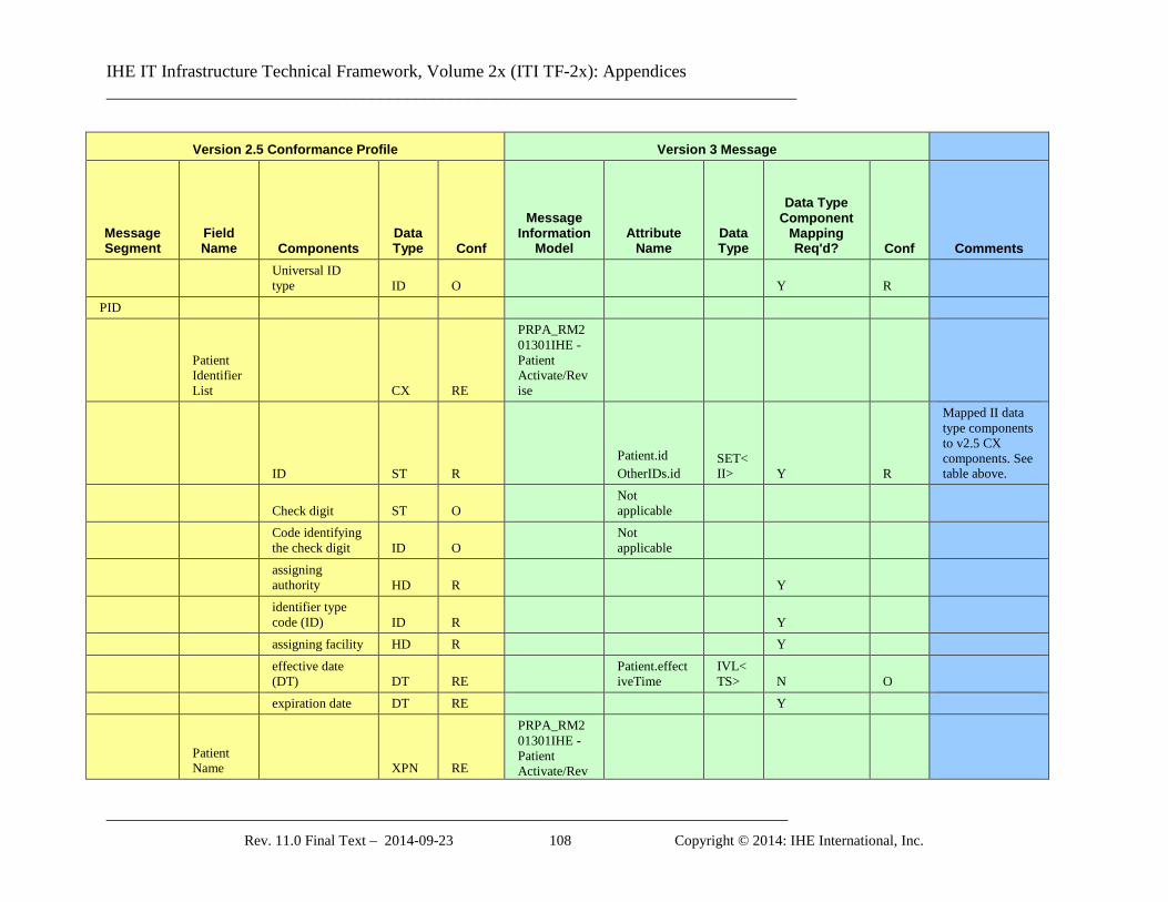
IHE IT Infrastructure Technical Framework, Volume 2x (ITI TF-2x): Appendices ______________________________________________________________________________
_____________________________________________________________________________ Rev. 11.0 Final Text – 2014-09-23 108 Copyright © 2014: IHE International, Inc.
Version 2.5 Conformance Profile Version 3 Message
Message Segment
Field Name Components
Data Type Conf
Message Information
Model Attribute
Name Data Type
Data Type Component
Mapping Req'd? Conf Comments
Universal ID type ID O Y R
PID
Patient Identifier List CX RE
PRPA_RM201301IHE - Patient Activate/Revise
ID ST R Patient.id OtherIDs.id
SET<II> Y R
Mapped II data type components to v2.5 CX components. See table above.
Check digit ST O Not applicable
Code identifying the check digit ID O
Not applicable
assigning authority HD R Y
identifier type code (ID) ID R Y
assigning facility HD R Y
effective date (DT) DT RE
Patient.effectiveTime
IVL<TS> N O
expiration date DT RE Y
Patient Name XPN RE
PRPA_RM201301IHE - Patient Activate/Rev
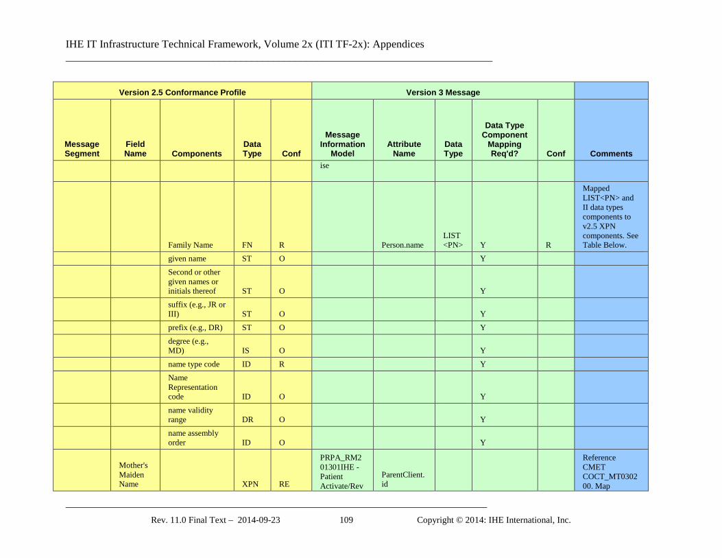
IHE IT Infrastructure Technical Framework, Volume 2x (ITI TF-2x): Appendices ______________________________________________________________________________
_____________________________________________________________________________ Rev. 11.0 Final Text – 2014-09-23 109 Copyright © 2014: IHE International, Inc.
Version 2.5 Conformance Profile Version 3 Message
Message Segment
Field Name Components
Data Type Conf
Message Information
Model Attribute
Name Data Type
Data Type Component
Mapping Req'd? Conf Comments
ise
Family Name FN R Person.name LIST<PN> Y R
Mapped LIST<PN> and II data types components to v2.5 XPN components. See Table Below.
given name ST O Y
Second or other given names or initials thereof ST O Y
suffix (e.g., JR or III) ST O Y
prefix (e.g., DR) ST O Y
degree (e.g., MD) IS O Y
name type code ID R Y
Name Representation code ID O Y
name validity range DR O Y
name assembly order ID O Y
Mother's Maiden Name XPN RE
PRPA_RM201301IHE - Patient Activate/Rev
ParentClient.id
Reference CMET COCT_MT030200. Map
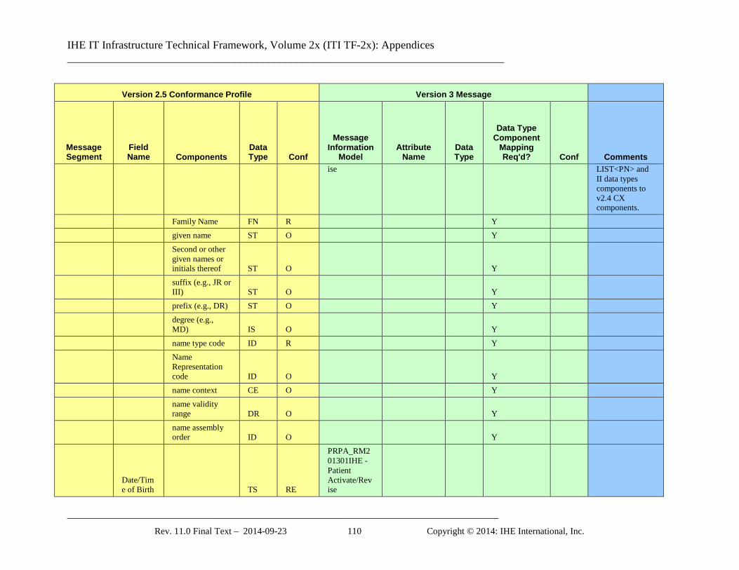
IHE IT Infrastructure Technical Framework, Volume 2x (ITI TF-2x): Appendices ______________________________________________________________________________
_____________________________________________________________________________ Rev. 11.0 Final Text – 2014-09-23 110 Copyright © 2014: IHE International, Inc.
Version 2.5 Conformance Profile Version 3 Message
Message Segment
Field Name Components
Data Type Conf
Message Information
Model Attribute
Name Data Type
Data Type Component
Mapping Req'd? Conf Comments
ise LIST<PN> and II data types components to v2.4 CX components.
Family Name FN R Y given name ST O Y
Second or other given names or initials thereof ST O Y
suffix (e.g., JR or III) ST O Y
prefix (e.g., DR) ST O Y
degree (e.g., MD) IS O Y
name type code ID R Y
Name Representation code ID O Y
name context CE O Y
name validity range DR O Y
name assembly order ID O Y
Date/Time of Birth TS RE
PRPA_RM201301IHE - Patient Activate/Revise
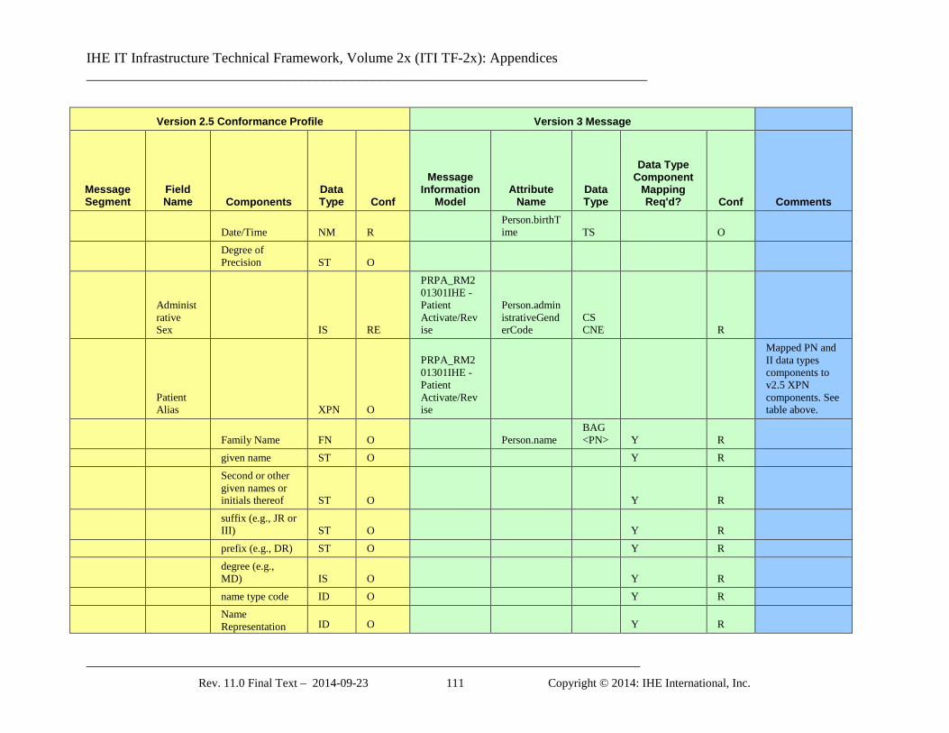
IHE IT Infrastructure Technical Framework, Volume 2x (ITI TF-2x): Appendices ______________________________________________________________________________
_____________________________________________________________________________ Rev. 11.0 Final Text – 2014-09-23 111 Copyright © 2014: IHE International, Inc.
Version 2.5 Conformance Profile Version 3 Message
Message Segment
Field Name Components
Data Type Conf
Message Information
Model Attribute
Name Data Type
Data Type Component
Mapping Req'd? Conf Comments
Date/Time NM R Person.birthTime TS O
Degree of Precision ST O
Administrative Sex IS RE
PRPA_RM201301IHE - Patient Activate/Revise
Person.administrativeGenderCode
CS CNE R
Patient Alias XPN O
PRPA_RM201301IHE - Patient Activate/Revise
Mapped PN and II data types components to v2.5 XPN components. See table above.
Family Name FN O Person.name BAG<PN> Y R
given name ST O Y R
Second or other given names or initials thereof ST O Y R
suffix (e.g., JR or III) ST O Y R
prefix (e.g., DR) ST O Y R
degree (e.g., MD) IS O Y R
name type code ID O Y R
Name Representation ID O Y R
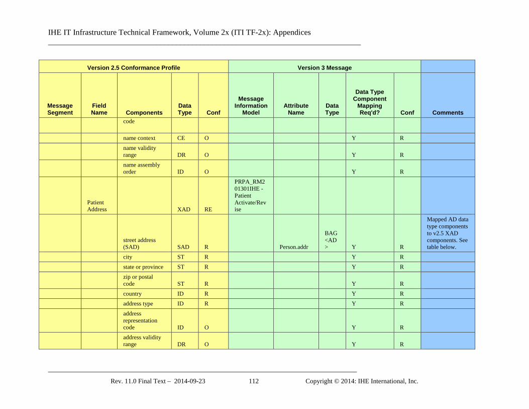
IHE IT Infrastructure Technical Framework, Volume 2x (ITI TF-2x): Appendices ______________________________________________________________________________
_____________________________________________________________________________ Rev. 11.0 Final Text – 2014-09-23 112 Copyright © 2014: IHE International, Inc.
Version 2.5 Conformance Profile Version 3 Message
Message Segment
Field Name Components
Data Type Conf
Message Information
Model Attribute
Name Data Type
Data Type Component
Mapping Req'd? Conf Comments
code
name context CE O Y R
name validity range DR O Y R
name assembly order ID O Y R
Patient Address XAD RE
PRPA_RM201301IHE - Patient Activate/Revise
street address (SAD) SAD R Person.addr
BAG <AD> Y R
Mapped AD data type components to v2.5 XAD components. See table below.
city ST R Y R state or province ST R Y R
zip or postal code ST R Y R
country ID R Y R address type ID R Y R
address representation code ID O Y R
address validity range DR O Y R
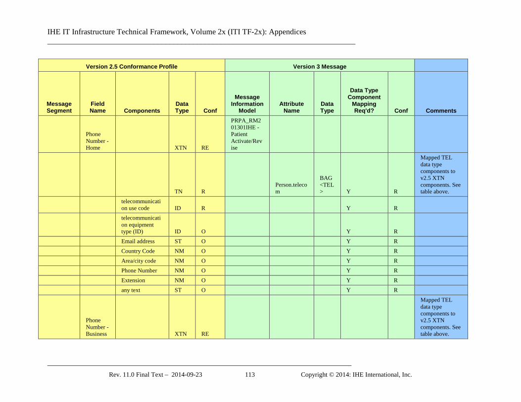
IHE IT Infrastructure Technical Framework, Volume 2x (ITI TF-2x): Appendices ______________________________________________________________________________
_____________________________________________________________________________ Rev. 11.0 Final Text – 2014-09-23 113 Copyright © 2014: IHE International, Inc.
Version 2.5 Conformance Profile Version 3 Message
Message Segment
Field Name Components
Data Type Conf
Message Information
Model Attribute
Name Data Type
Data Type Component
Mapping Req'd? Conf Comments
Phone Number - Home XTN RE
PRPA_RM201301IHE - Patient Activate/Revise
TN R Person.telecom
BAG <TEL> Y R
Mapped TEL data type components to v2.5 XTN components. See table above.
telecommunication use code ID R Y R
telecommunication equipment type (ID) ID O Y R
Email address ST O Y R Country Code NM O Y R Area/city code NM O Y R Phone Number NM O Y R Extension NM O Y R any text ST O Y R
Phone Number - Business XTN RE
Mapped TEL data type components to v2.5 XTN components. See table above.
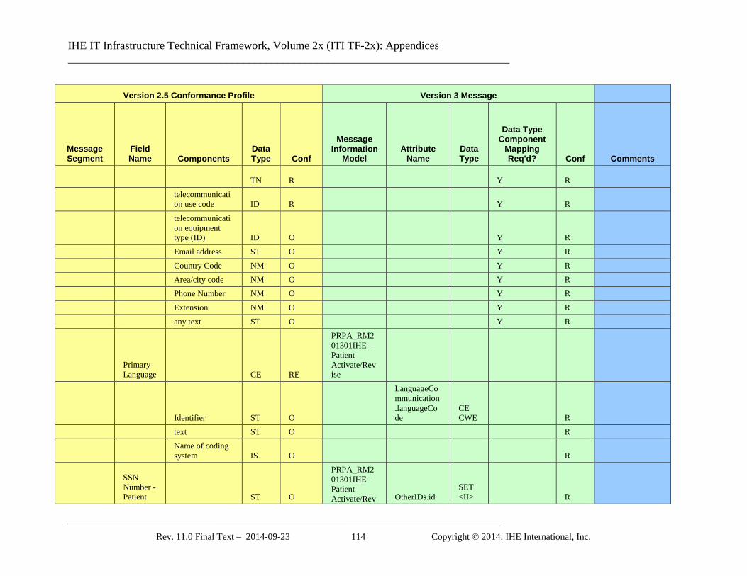
IHE IT Infrastructure Technical Framework, Volume 2x (ITI TF-2x): Appendices ______________________________________________________________________________
_____________________________________________________________________________ Rev. 11.0 Final Text – 2014-09-23 114 Copyright © 2014: IHE International, Inc.
Version 2.5 Conformance Profile Version 3 Message
Message Segment
Field Name Components
Data Type Conf
Message Information
Model Attribute
Name Data Type
Data Type Component
Mapping Req'd? Conf Comments
TN R Y R
telecommunication use code ID R Y R
telecommunication equipment type (ID) ID O Y R
Email address ST O Y R Country Code NM O Y R Area/city code NM O Y R Phone Number NM O Y R Extension NM O Y R any text ST O Y R
Primary Language CE RE
PRPA_RM201301IHE - Patient Activate/Revise
Identifier ST O
LanguageCommunication.languageCode
CE CWE R
text ST O R
Name of coding system IS O R
SSN Number - Patient ST O
PRPA_RM201301IHE - Patient Activate/Rev OtherIDs.id
SET <II> R
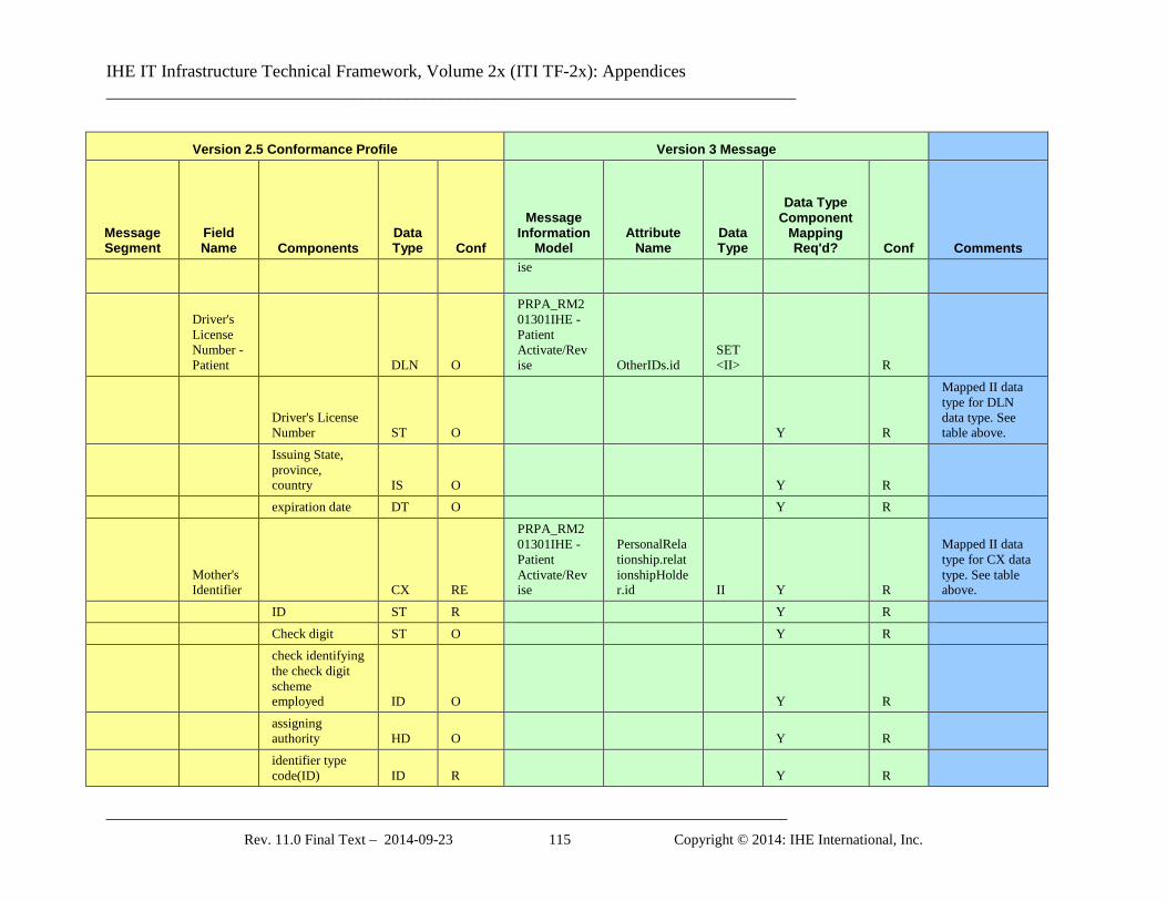
IHE IT Infrastructure Technical Framework, Volume 2x (ITI TF-2x): Appendices ______________________________________________________________________________
_____________________________________________________________________________ Rev. 11.0 Final Text – 2014-09-23 115 Copyright © 2014: IHE International, Inc.
Version 2.5 Conformance Profile Version 3 Message
Message Segment
Field Name Components
Data Type Conf
Message Information
Model Attribute
Name Data Type
Data Type Component
Mapping Req'd? Conf Comments
ise
Driver's License Number - Patient DLN O
PRPA_RM201301IHE - Patient Activate/Revise OtherIDs.id
SET <II> R
Driver's License Number ST O Y R
Mapped II data type for DLN data type. See table above.
Issuing State, province, country IS O Y R
expiration date DT O Y R
Mother's Identifier CX RE
PRPA_RM201301IHE - Patient Activate/Revise
PersonalRelationship.relationshipHolder.id II Y R
Mapped II data type for CX data type. See table above.
ID ST R Y R Check digit ST O Y R
check identifying the check digit scheme employed ID O Y R
assigning authority HD O Y R
identifier type code(ID) ID R Y R

IHE IT Infrastructure Technical Framework, Volume 2x (ITI TF-2x): Appendices ______________________________________________________________________________
_____________________________________________________________________________ Rev. 11.0 Final Text – 2014-09-23 116 Copyright © 2014: IHE International, Inc.
Version 2.5 Conformance Profile Version 3 Message
Message Segment
Field Name Components
Data Type Conf
Message Information
Model Attribute
Name Data Type
Data Type Component
Mapping Req'd? Conf Comments
assigning facility HD O Y R
effective date (DT) DT O Y R
expiration date DT O Y R
Ethnic Group CE O
Birth Order NM RE
PRPA_RM201301IHE - Patient Activate/Revise
Person.multipleBirthOrderNumber R
Patient Death Date and Time TS RE
PRPA_RM201301IHE - Patient Activate/Revise Y R
Date/Time NM O
PRPA_RM201301IHE - Patient Activate/Revise
Person.deceasedTime TS O
Degree of Precision ST O
Patient Death Indicator ID RE
PRPA_RM201301IHE - Patient Activate/Revise
Person.deceasedInd BL O
Last Update TS O Metadata
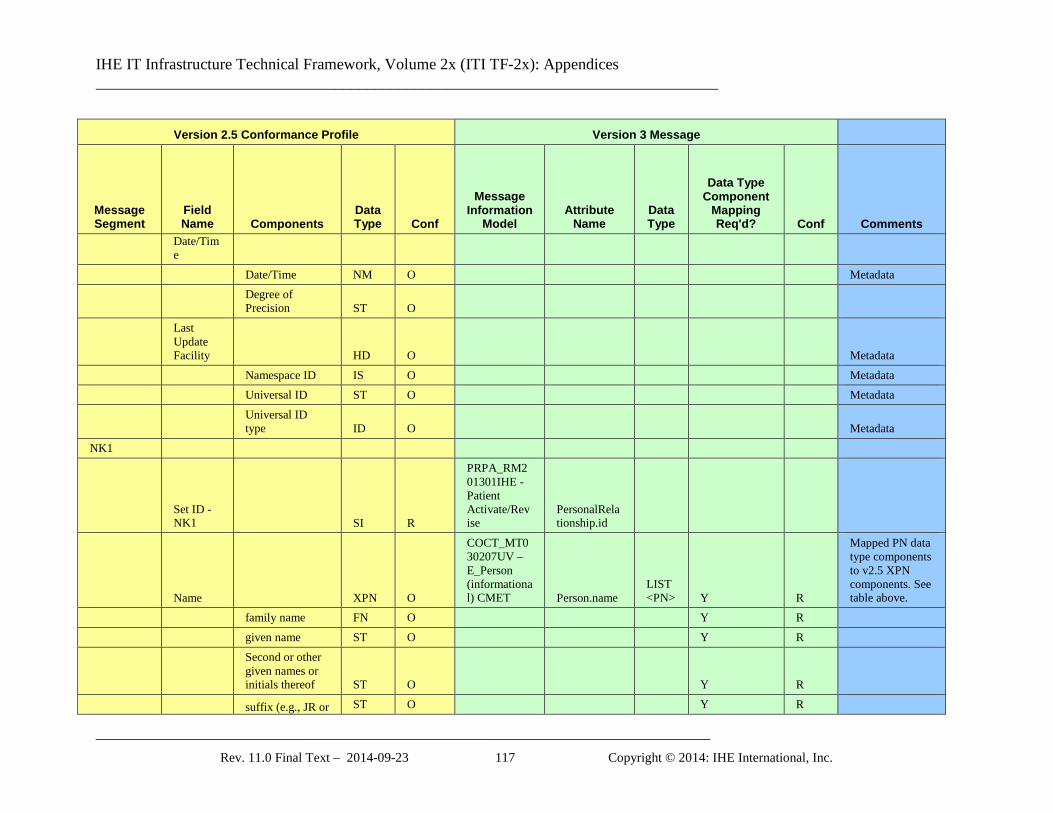
IHE IT Infrastructure Technical Framework, Volume 2x (ITI TF-2x): Appendices ______________________________________________________________________________
_____________________________________________________________________________ Rev. 11.0 Final Text – 2014-09-23 117 Copyright © 2014: IHE International, Inc.
Version 2.5 Conformance Profile Version 3 Message
Message Segment
Field Name Components
Data Type Conf
Message Information
Model Attribute
Name Data Type
Data Type Component
Mapping Req'd? Conf Comments
Date/Time
Date/Time NM O Metadata
Degree of Precision ST O
Last Update Facility HD O Metadata
Namespace ID IS O Metadata Universal ID ST O Metadata
Universal ID type ID O Metadata
NK1
Set ID - NK1 SI R
PRPA_RM201301IHE - Patient Activate/Revise
PersonalRelationship.id
Name XPN O
COCT_MT030207UV – E_Person (informational) CMET Person.name
LIST <PN> Y R
Mapped PN data type components to v2.5 XPN components. See table above.
family name FN O Y R given name ST O Y R
Second or other given names or initials thereof ST O Y R
suffix (e.g., JR or ST O Y R
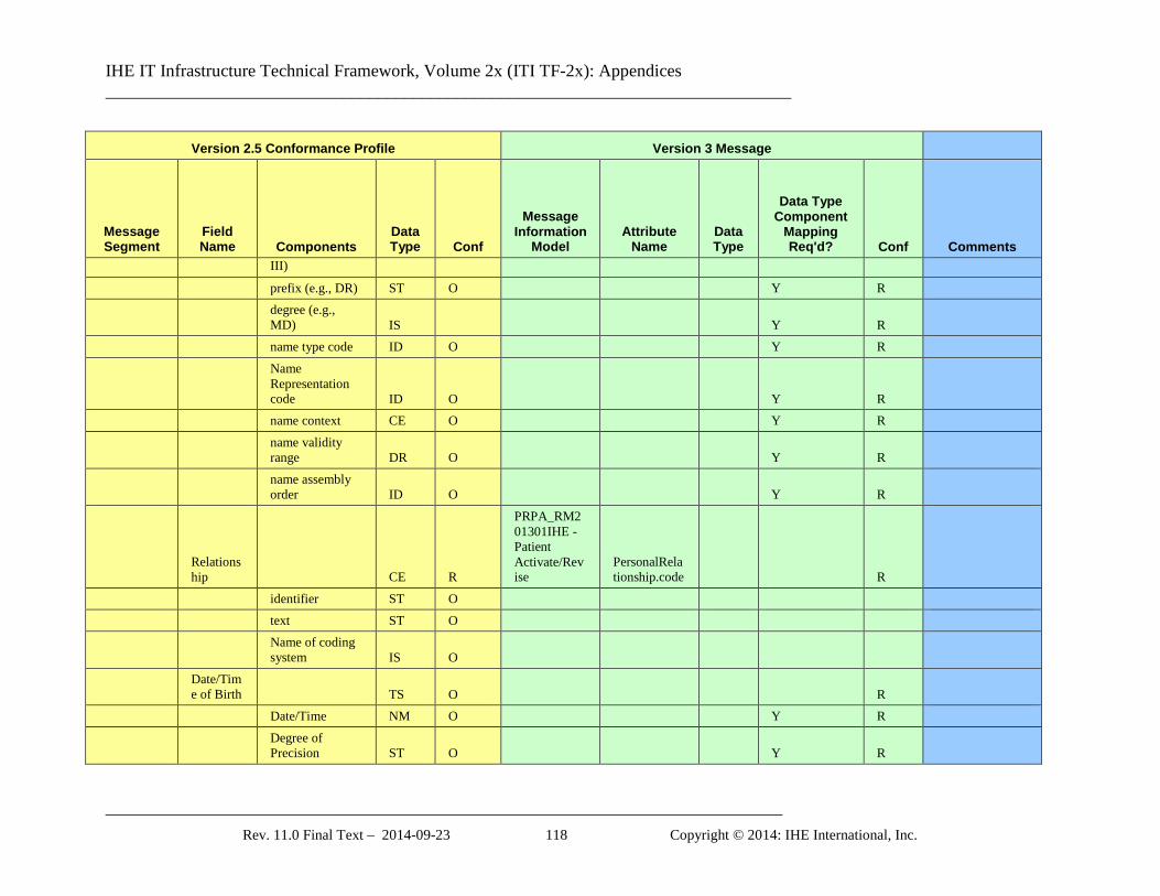
IHE IT Infrastructure Technical Framework, Volume 2x (ITI TF-2x): Appendices ______________________________________________________________________________
_____________________________________________________________________________ Rev. 11.0 Final Text – 2014-09-23 118 Copyright © 2014: IHE International, Inc.
Version 2.5 Conformance Profile Version 3 Message
Message Segment
Field Name Components
Data Type Conf
Message Information
Model Attribute
Name Data Type
Data Type Component
Mapping Req'd? Conf Comments
III)
prefix (e.g., DR) ST O Y R
degree (e.g., MD) IS Y R
name type code ID O Y R
Name Representation code ID O Y R
name context CE O Y R
name validity range DR O Y R
name assembly order ID O Y R
Relationship CE R
PRPA_RM201301IHE - Patient Activate/Revise
PersonalRelationship.code R
identifier ST O text ST O
Name of coding system IS O
Date/Time of Birth TS O R
Date/Time NM O Y R
Degree of Precision ST O Y R
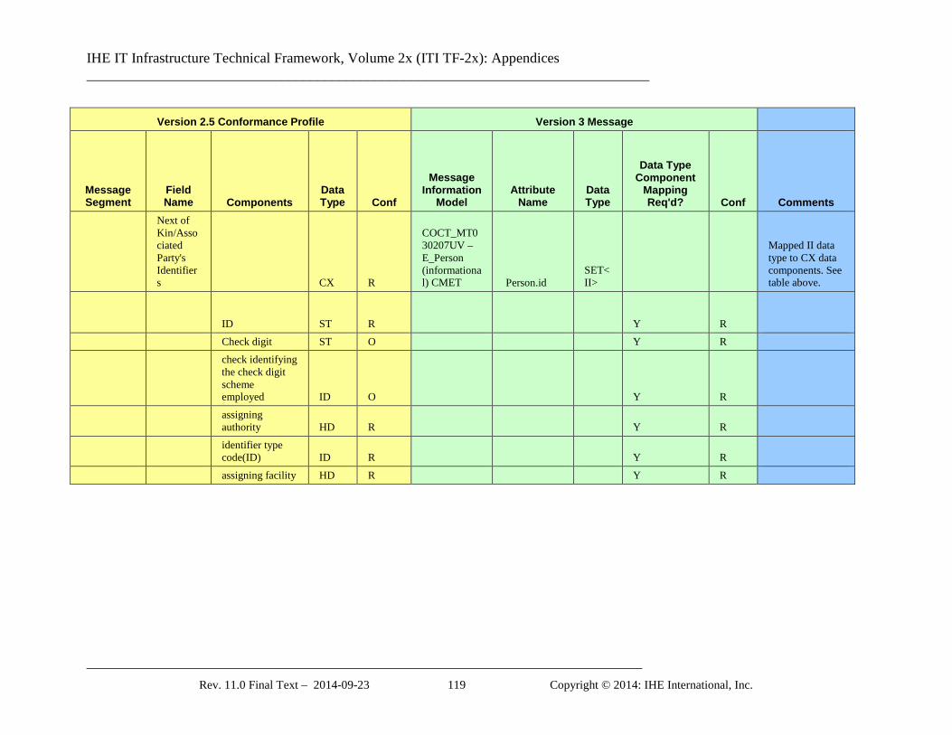
IHE IT Infrastructure Technical Framework, Volume 2x (ITI TF-2x): Appendices ______________________________________________________________________________
_____________________________________________________________________________ Rev. 11.0 Final Text – 2014-09-23 119 Copyright © 2014: IHE International, Inc.
Version 2.5 Conformance Profile Version 3 Message
Message Segment
Field Name Components
Data Type Conf
Message Information
Model Attribute
Name Data Type
Data Type Component
Mapping Req'd? Conf Comments
Next of Kin/Associated Party's Identifiers CX R
COCT_MT030207UV – E_Person (informational) CMET Person.id
SET<II>
Mapped II data type to CX data components. See table above.
ID ST R Y R Check digit ST O Y R
check identifying the check digit scheme employed ID O Y R
assigning authority HD R Y R
identifier type code(ID) ID R Y R
assigning facility HD R Y R
IHE IT Infrastructure Technical Framework, Volume 2x (ITI TF-2x): Appendices ______________________________________________________________________________
_____________________________________________________________________________ Rev. 11.0 Final Text – 2014-09-23 120 Copyright © 2014: IHE International, Inc.
Appendix S: Intentionally Left Blank
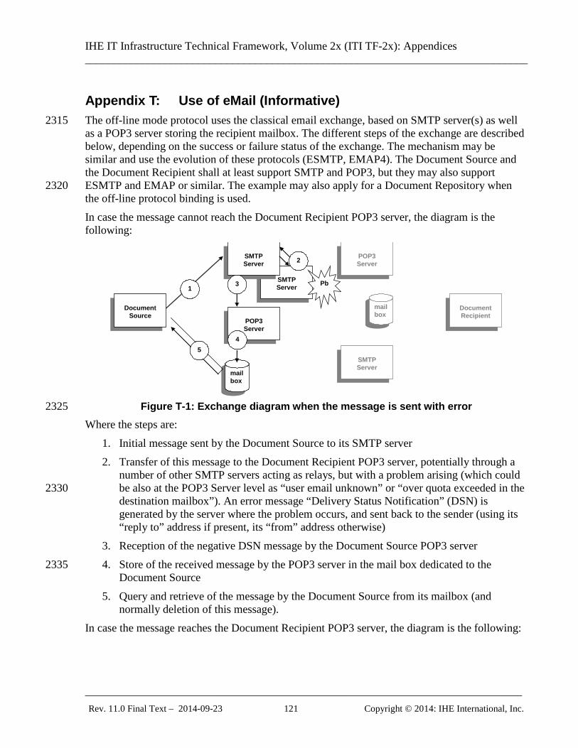
IHE IT Infrastructure Technical Framework, Volume 2x (ITI TF-2x): Appendices ______________________________________________________________________________
_____________________________________________________________________________ Rev. 11.0 Final Text – 2014-09-23 121 Copyright © 2014: IHE International, Inc.
Appendix T: Use of eMail (Informative) The off-line mode protocol uses the classical email exchange, based on SMTP server(s) as well 2315 as a POP3 server storing the recipient mailbox. The different steps of the exchange are described below, depending on the success or failure status of the exchange. The mechanism may be similar and use the evolution of these protocols (ESMTP, EMAP4). The Document Source and the Document Recipient shall at least support SMTP and POP3, but they may also support ESMTP and EMAP or similar. The example may also apply for a Document Repository when 2320 the off-line protocol binding is used. In case the message cannot reach the Document Recipient POP3 server, the diagram is the following:
SMTP Server
Document
Source
Document Recipient
SMTP Server
POP3 Server
mailbox
1 Pb
2
3
POP3 Server
mailbox
5 SMTP Server
4
Figure T-1: Exchange diagram when the message is sent with error 2325
Where the steps are: 1. Initial message sent by the Document Source to its SMTP server 2. Transfer of this message to the Document Recipient POP3 server, potentially through a
number of other SMTP servers acting as relays, but with a problem arising (which could be also at the POP3 Server level as “user email unknown” or “over quota exceeded in the 2330 destination mailbox”). An error message “Delivery Status Notification” (DSN) is generated by the server where the problem occurs, and sent back to the sender (using its “reply to” address if present, its “from” address otherwise)
3. Reception of the negative DSN message by the Document Source POP3 server 4. Store of the received message by the POP3 server in the mail box dedicated to the 2335
Document Source 5. Query and retrieve of the message by the Document Source from its mailbox (and
normally deletion of this message). In case the message reaches the Document Recipient POP3 server, the diagram is the following:
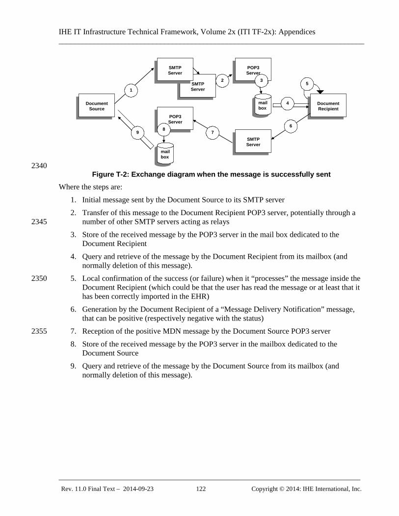
IHE IT Infrastructure Technical Framework, Volume 2x (ITI TF-2x): Appendices ______________________________________________________________________________
_____________________________________________________________________________ Rev. 11.0 Final Text – 2014-09-23 122 Copyright © 2014: IHE International, Inc.
SMTP Server
Document
Source
Document Recipient
SMTP Server
POP3 Server
mailbox
1
2 3
4
POP3 Server
mailbox
5
6 7 8
SMTP Server
9
2340 Figure T-2: Exchange diagram when the message is successfully sent
Where the steps are: 1. Initial message sent by the Document Source to its SMTP server 2. Transfer of this message to the Document Recipient POP3 server, potentially through a
number of other SMTP servers acting as relays 2345 3. Store of the received message by the POP3 server in the mail box dedicated to the
Document Recipient 4. Query and retrieve of the message by the Document Recipient from its mailbox (and
normally deletion of this message). 5. Local confirmation of the success (or failure) when it “processes” the message inside the 2350
Document Recipient (which could be that the user has read the message or at least that it has been correctly imported in the EHR)
6. Generation by the Document Recipient of a “Message Delivery Notification” message, that can be positive (respectively negative with the status)
7. Reception of the positive MDN message by the Document Source POP3 server 2355 8. Store of the received message by the POP3 server in the mailbox dedicated to the
Document Source 9. Query and retrieve of the message by the Document Source from its mailbox (and
normally deletion of this message).
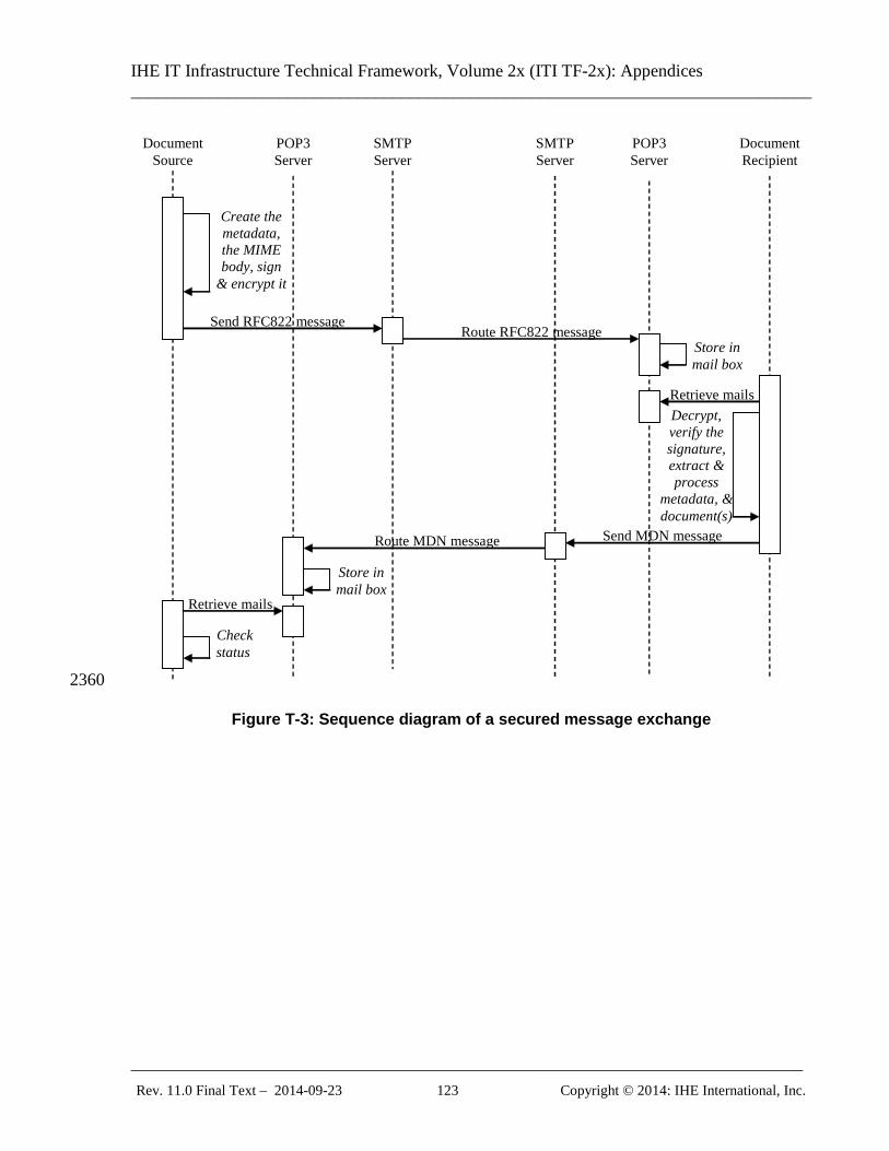
IHE IT Infrastructure Technical Framework, Volume 2x (ITI TF-2x): Appendices ______________________________________________________________________________
_____________________________________________________________________________ Rev. 11.0 Final Text – 2014-09-23 123 Copyright © 2014: IHE International, Inc.
SMTP Server
SMTP Server
Send MDN message
Document Source
Document Recipient
POP3 Server
POP3 Server
Create the metadata, the MIME body, sign
& encrypt it
Send RFC822 message Route RFC822 message
Store in mail box
Retrieve mails Decrypt, verify the signature, extract & process
metadata, & document(s)
Retrieve mails
Route MDN message
Store in mail box
Check status
2360
Figure T-3: Sequence diagram of a secured message exchange

IHE IT Infrastructure Technical Framework, Volume 2x (ITI TF-2x): Appendices ______________________________________________________________________________
_____________________________________________________________________________ Rev. 11.0 Final Text – 2014-09-23 124 Copyright © 2014: IHE International, Inc.
Appendix U: Intentionally Left Blank 2365
IHE IT Infrastructure Technical Framework, Volume 2x (ITI TF-2x): Appendices ______________________________________________________________________________
_____________________________________________________________________________ Rev. 11.0 Final Text – 2014-09-23 125 Copyright © 2014: IHE International, Inc.
Appendix V: Web Services for IHE Transactions
V.1: Introduction “Web Services” has become a catch-all phrase describing a wide range of HTTP transactions 2370 over a TCP/IP network. A more precise definition of Web Services implies richer infrastructure capabilities with all transactions built using SOAP messages. This appendix provides the guidelines for specifying the use of SOAP-based Web Services as the messaging infrastructure and transport mechanism for IHE transactions.
V.2: Relevant Standards 2375
Virtually all web services specifications are developed under the auspices of the World Wide Web Consortium (W3C) or the Organization for the Advancement of Structured Information Standards (OASIS). The Web Services-Interoperability organization (WS-I) publishes profiles, which incorporate several existing standards, and constrain them for interoperability. For each profile, WS-I also publishes a test assertion document and corresponding interoperability testing 2380 tools for Java and C#.
V.2.1: WS-I Profiles The Web Services for IHE transactions will be based on SOAP 1.2, and as such they take advantage of the guidelines expressed in the WS-I Basic Profile 2.0 (BP 2.0). Some IHE transactions may also take advantage of the WS-I Basic Security Profile 1.1 (BSP 1.1) and WS-I 2385 Reliable Secure Profile 1.0 (RSP 1.0) where applicable. For the rare cases, where IHE transactions may need to support SOAP 1.1 in addition to the required SOAP 1.2 version, the appendix provides the corresponding requirements following the guidelines from WS-I Basic Profile 1.2 (BP 1.2).
V.2.2: WS-* Specifications 2390 Based on the requirements of the current WS-I profiles, the Web Services for IHE transactions support the following Web Services standards:
• WS-Addressing
• MTOM
• XOP 2395
• WS-Security The WS-I Reliable Secure Profile combines several of the above WS-* standards, as well as including:
• WS-SecureConversation
• WS-Trust 2400
• WS-Policy
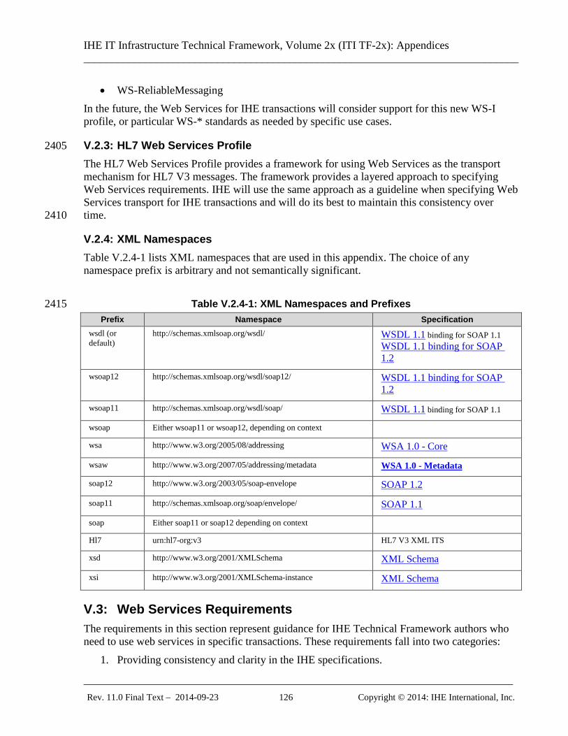
IHE IT Infrastructure Technical Framework, Volume 2x (ITI TF-2x): Appendices ______________________________________________________________________________
_____________________________________________________________________________ Rev. 11.0 Final Text – 2014-09-23 126 Copyright © 2014: IHE International, Inc.
• WS-ReliableMessaging In the future, the Web Services for IHE transactions will consider support for this new WS-I profile, or particular WS-* standards as needed by specific use cases.
V.2.3: HL7 Web Services Profile 2405 The HL7 Web Services Profile provides a framework for using Web Services as the transport mechanism for HL7 V3 messages. The framework provides a layered approach to specifying Web Services requirements. IHE will use the same approach as a guideline when specifying Web Services transport for IHE transactions and will do its best to maintain this consistency over time. 2410
V.2.4: XML Namespaces Table V.2.4-1 lists XML namespaces that are used in this appendix. The choice of any namespace prefix is arbitrary and not semantically significant.
Table V.2.4-1: XML Namespaces and Prefixes 2415 Prefix Namespace Specification
wsdl (or default)
http://schemas.xmlsoap.org/wsdl/ WSDL 1.1 binding for SOAP 1.1 WSDL 1.1 binding for SOAP 1.2
wsoap12 http://schemas.xmlsoap.org/wsdl/soap12/ WSDL 1.1 binding for SOAP 1.2
wsoap11 http://schemas.xmlsoap.org/wsdl/soap/ WSDL 1.1 binding for SOAP 1.1
wsoap Either wsoap11 or wsoap12, depending on context
wsa http://www.w3.org/2005/08/addressing WSA 1.0 - Core
wsaw http://www.w3.org/2007/05/addressing/metadata WSA 1.0 - Metadata
soap12 http://www.w3.org/2003/05/soap-envelope SOAP 1.2
soap11 http://schemas.xmlsoap.org/soap/envelope/ SOAP 1.1
soap Either soap11 or soap12 depending on context
Hl7 urn:hl7-org:v3 HL7 V3 XML ITS
xsd http://www.w3.org/2001/XMLSchema XML Schema
xsi http://www.w3.org/2001/XMLSchema-instance XML Schema
V.3: Web Services Requirements The requirements in this section represent guidance for IHE Technical Framework authors who need to use web services in specific transactions. These requirements fall into two categories:
1. Providing consistency and clarity in the IHE specifications.
IHE IT Infrastructure Technical Framework, Volume 2x (ITI TF-2x): Appendices ______________________________________________________________________________
_____________________________________________________________________________ Rev. 11.0 Final Text – 2014-09-23 127 Copyright © 2014: IHE International, Inc.
2. Affecting the wire format of the transactions. 2420 Note: When the requirements for particular text are specified, the following notation is used:
• curly braces (i.e., {}) are used to denote a part of a string which shall always be replaced with a string corresponding to the specific transaction, actor, or profile;
• square brackets (i.e., []) are used to denote a part of a string which shall be either replaced with a string corresponding to the specific transaction, or shall be completely omitted. 2425
V.3.1: Requirements for Transactions using HL7 V3 Messages When IHE transactions use HL7 V3 Messages, the Web Services protocol will conform to the HL7 Web Services Basic, Addressing, Security, and Reliable Messaging Profiles, with additional constraints as specified in the following sub-sections.
V.3.1.1: HL7 WS Basic Profile Constraints 2430 The Sender and Receiver shall conform to the HL7 WS Basic Profile with five modifications. The first modification is the requirement of supporting SOAP 1.2, while the HL7 WS Basic Profile provides the choice of supporting either SOAP 1.1 or SOAP 1.2, or both. The second modification is to HL7-WSP200, which recommends that a WSDL document describes a specific HL7 application role. For consistency with non-HL7 V3 transactions, IHE 2435 specifications shall provide an example WSDL document for all transactions of an actor per profile (see IHE-WSP200). The third modification is to HL7-WSP201, which recommends that the HL7 Application Role ID is to be used as the name of the WSDL definition. For consistency with non-HL7 V3 transactions the name of the example WSDL definition provided in the IHE specification shall be the actor 2440 name of the transaction's receiver (see the IHE-WSP201). The fourth modification is to HL7-WSP202, which specifies the use of the HL7 namespace as the target namespace of the WSDL document. This would prevent creating a single WSDL for actors which use both HL7 V3 and non-HL7 V3 IHE transactions (e.g., an XDS registry implementing the XDS.b Profile with the Patient Identity Feed HL7 V3 transaction). For 2445 consistency among all IHE transactions, when creating an IHE transaction specification, the WSDL target namespace shall be specified as “urn:ihe:<committee name>:<profile>:<year> (see IHE-WSP202). The fifth modification is to HL7-WSP208, which specifies that “WSDL messages for Interactions SHOULD use wsdl:operation/wsdl:input/@wsa:Action = "urn:hl7-2450 org:v3:{Interaction_Artifact_Id}”. IHE extends the “should” to support situations where one HL7 message is being used within two transactions for significantly different purposes. For this case the second use of the message shall extend the HL7 specified Action string with “:[transaction-name]” where [transaction-name] is the name of the second transaction.
V.3.1.2: HL7 WS Addressing Profile Constraints 2455 The Sender and Receiver should conform to the HL7 WS Addressing Profile. No additional constraints are made in this sub-section.
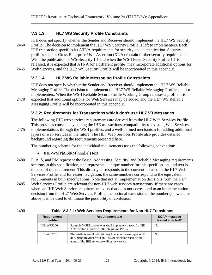
IHE IT Infrastructure Technical Framework, Volume 2x (ITI TF-2x): Appendices ______________________________________________________________________________
_____________________________________________________________________________ Rev. 11.0 Final Text – 2014-09-23 128 Copyright © 2014: IHE International, Inc.
V.3.1.3: HL7 WS Security Profile Constraints IHE does not specify whether the Sender and Receiver should implement the HL7 WS Security Profile. The decision to implement the HL7 WS Security Profile is left to implementers. Each 2460 IHE transaction specifies its ATNA requirements for security and authentication. Security profiles such as Cross-Enterprise User Assertion (XUA) contain further security requirements. With the publication of WS-Security 1.1 and when the WS-I Basic Security Profile 1.1 is released, it is expected that ATNA (or a different profile) may incorporate additional options for Web Services, and the HL7 WS Security Profile will be incorporated in this appendix. 2465
V.3.1.4: HL7 WS Reliable Messaging Profile Constraints IHE does not specify whether the Sender and Receiver should implement the HL7 WS Reliable Messaging Profile. The decision to implement the HL7 WS Reliable Messaging Profile is left to implementers. When the WS-I Reliable Secure Profile Working Group releases a profile it is expected that additional options for Web Services may be added, and the HL7 WS Reliable 2470 Messaging Profile will be incorporated in this appendix.
V.3.2: Requirements for Transactions which don’t use HL7 V3 Messages The following IHE web services requirements are derived from the HL7 Web Services Profile. This provides consistency among the IHE transactions, compatibility to existing Web Services implementations through the WS-I profiles, and a well-defined mechanism for adding additional 2475 layers of web services in the future. The HL7 Web Services Profile also provides detailed background regarding the requirements presented here. The numbering scheme for the individual requirements uses the following convention:
• IHE-WS[P|A|S|RM]nnn[.e]) text P, A, S, and RM represent the Basic, Addressing, Security, and Reliable Messaging requirements 2480 sections in this specification, nnn represents a unique number for this specification, and text is the text of the requirement. This directly corresponds to the convention used in the HL7 Web Services Profile, and for easier navigation, the same numbers correspond to the equivalent requirements in both specifications. Note that not all implementation decisions from the HL7 Web Services Profile are relevant for non-HL7 web services transactions. If there are cases 2485 where an IHE Web Services requirement exists that does not correspond to an implementation decision from the HL7 Web Services Profile, the optional extension to the number (shown as .e above) can be used to eliminate the possibility of confusion.
Table V.3.2-1: Web Services Requirements for Non-HL7 Transitions 2490 Requirement
Identifier Requirement text SOAP message
format affected? IHE-WSP200 Example WSDL documents shall implement a specific IHE
Actor within a specific IHE Integration Profile. No
IHE-WSP201 The attribute /wsdl:definitions/@name in the example WSDL document provided with an IHE specification shall be the name of the IHE Actor providing the service.
No
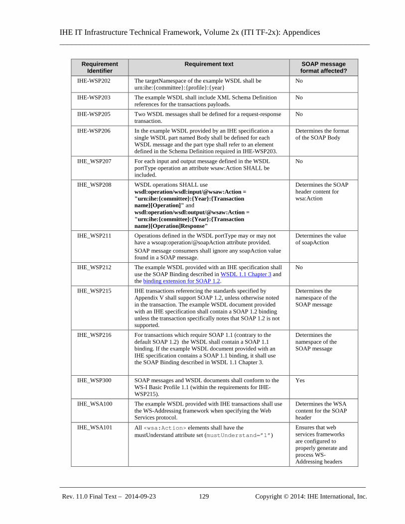
IHE IT Infrastructure Technical Framework, Volume 2x (ITI TF-2x): Appendices ______________________________________________________________________________
_____________________________________________________________________________ Rev. 11.0 Final Text – 2014-09-23 129 Copyright © 2014: IHE International, Inc.
Requirement Identifier
Requirement text SOAP message format affected?
IHE-WSP202 The targetNamespace of the example WSDL shall be urn:ihe:{committee}:{profile}:{year}
No
IHE-WSP203 The example WSDL shall include XML Schema Definition references for the transactions payloads.
No
IHE-WSP205 Two WSDL messages shall be defined for a request-response transaction.
No
IHE-WSP206 In the example WSDL provided by an IHE specification a single WSDL part named Body shall be defined for each WSDL message and the part type shall refer to an element defined in the Schema Definition required in IHE-WSP203.
Determines the format of the SOAP Body
IHE_WSP207 For each input and output message defined in the WSDL portType operation an attribute wsaw:Action SHALL be included.
No
IHE_WSP208 WSDL operations SHALL use wsdl:operation/wsdl:input/@wsaw:Action = "urn:ihe:{committee}:{Year}:{Transaction name}[Operation]" and wsdl:operation/wsdl:output/@wsaw:Action = "urn:ihe:{committee}:{Year}:{Transaction name}[Operation]Response"
Determines the SOAP header content for wsa:Action
IHE_WSP211 Operations defined in the WSDL portType may or may not have a wsoap:operation/@soapAction attribute provided. SOAP message consumers shall ignore any soapAction value found in a SOAP message.
Determines the value of soapAction
IHE_WSP212 The example WSDL provided with an IHE specification shall use the SOAP Binding described in WSDL 1.1 Chapter 3 and the binding extension for SOAP 1.2.
No
IHE_WSP215 IHE transactions referencing the standards specified by Appendix V shall support SOAP 1.2, unless otherwise noted in the transaction. The example WSDL document provided with an IHE specification shall contain a SOAP 1.2 binding unless the transaction specifically notes that SOAP 1.2 is not supported.
Determines the namespace of the SOAP message
IHE_WSP216 For transactions which require SOAP 1.1 (contrary to the default SOAP 1.2) the WSDL shall contain a SOAP 1.1 binding. If the example WSDL document provided with an IHE specification contains a SOAP 1.1 binding, it shall use the SOAP Binding described in WSDL 1.1 Chapter 3.
Determines the namespace of the SOAP message
IHE_WSP300 SOAP messages and WSDL documents shall conform to the WS-I Basic Profile 1.1 (within the requirements for IHE-WSP215).
Yes
IHE_WSA100 The example WSDL provided with IHE transactions shall use the WS-Addressing framework when specifying the Web Services protocol.
Determines the WSA content for the SOAP header
IHE_WSA101 All <wsa:Action> elements shall have the mustUnderstand attribute set (mustUnderstand=”1”)
Ensures that web services frameworks are configured to properly generate and process WS-Addressing headers
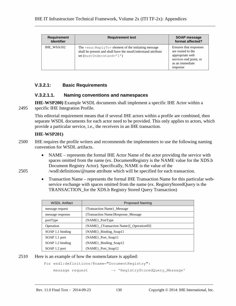
IHE IT Infrastructure Technical Framework, Volume 2x (ITI TF-2x): Appendices ______________________________________________________________________________
_____________________________________________________________________________ Rev. 11.0 Final Text – 2014-09-23 130 Copyright © 2014: IHE International, Inc.
Requirement Identifier
Requirement text SOAP message format affected?
IHE_WSA102 The <wsa:ReplyTo> element of the initiating message shall be present and shall have the mustUnderstand attribute set (mustUnderstand=”1”)
Ensures that responses are routed to the appropriate web services end point, or as an immediate response
V.3.2.1: Basic Requirements
V.3.2.1.1. Naming conventions and namespaces IHE-WSP200) Example WSDL documents shall implement a specific IHE Actor within a specific IHE Integration Profile. 2495 This editorial requirement means that if several IHE actors within a profile are combined, then separate WSDL documents for each actor need to be provided. This only applies to actors, which provide a particular service, i.e., the receivers in an IHE transaction.
IHE-WSP201) IHE requires the profile writers and recommends the implementers to use the following naming 2500 convention for WSDL artifacts.
• NAME – represents the formal IHE Actor Name of the actor providing the service with spaces omitted from the name (ex. DocumentRegistry is the NAME value for the XDS.b Document Registry Actor). Specifically, NAME is the value of the /wsdl:definitions/@name attribute which will be specified for each transaction. 2505
• Transaction Name – represents the formal IHE Transaction Name for this particular web-service exchange with spaces omitted from the name (ex. RegistryStoredQuery is the TRANSACTION_for the XDS.b Registry Stored Query Transaction)
WSDL Artifact Proposed Naming
message request {Transaction Name}_Message message response {Transaction Name}Response_Message portType {NAME}_PortType Operation {NAME}_{Transaction Name}[_OperationID] SOAP 1.1 binding {NAME}_Binding_Soap11 SOAP 1.1 port {NAME}_Port_Soap11 SOAP 1.2 binding {NAME}_Binding_Soap12 SOAP 1.2 port {NAME}_Port_Soap12
Here is an example of how the nomenclature is applied: 2510 For wsdl:definitions/@name="DocumentRegistry":
message request -> "RegistryStoredQuery_Message"

IHE IT Infrastructure Technical Framework, Volume 2x (ITI TF-2x): Appendices ______________________________________________________________________________
_____________________________________________________________________________ Rev. 11.0 Final Text – 2014-09-23 131 Copyright © 2014: IHE International, Inc.
message response -> RegistryStoredQueryResponse_Message
portType -> "DocumentRegistry_PortType"
operation -> "DocumentRegistry_RegistryStoredQuery_Request" 2515 SOAP 1.2 binding -> "DocumentRegistry_Binding_Soap12"
SOAP 1.2 port -> "DocumentRegistry_Port_Soap12"
SOAP 1.1 binding -> "DocumentRegistry_Binding_Soap11"
SOAP 1.1 port -> "DocumentRegistry_Port_Soap11"
IHE-WSP202) 2520 IHE requires the use of the following naming convention for targetNamespace of example WSDL.
• DOMAIN – represents the acronym of the IHE domain who authored this web-service transaction (ex. iti)
• PROFILE – represents the acronym of the IHE profile which references this web-service 2525 transaction (ex. xds-b)
• YEAR – represents the four digit year that this transaction was first published within a Trial Implementation profile
• TYPE – optional extension of which other IHE specifications already using XML namespaces may make use 2530
The targetNamespace of the example WSDL shall be urn:ihe:{DOMAIN}:{PROFILE}:{YEAR} and may be extended to urn:ihe:{DOMAIN}:{PROFILE}:{YEAR}:{TYPE}
As an example the namespace for the 2008 XDS.b Integration Profile is urn:ihe:iti:xds-b:2007. 2535
IHE-WSP203) The example WSDL shall include XML Schema Definition references for the transactions payloads. The purpose of this requirement is to specify how authors of IHE profiles specify the transactions which use web services. This requires both the existence of an XML schema definition for the transaction payloads, and the manner in which it is specified in the WSDL file 2540 – by reference.
V.3.2.1.2: Message and portType Definitions IHE-WSP205) Two WSDL messages shall be defined for a request-response transaction. IHE-WSP206) In the example WSDL provided by an IHE specification a single WSDL part named Body shall be defined for each WSDL message and the part type shall refer to an element 2545 defined in the Schema Definition required in IHE-WSP203. IHE-WSP207) For each input and output message defined in the WSDL portType operation an attribute wsaw:Action SHALL be included.
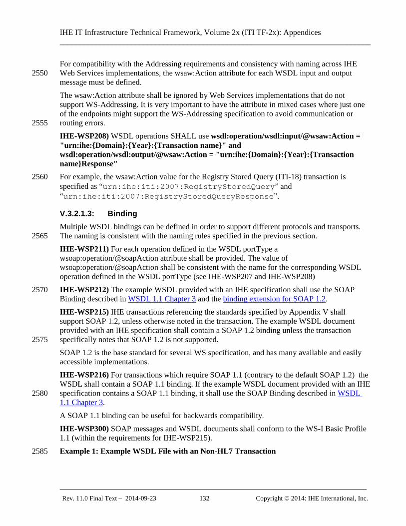
IHE IT Infrastructure Technical Framework, Volume 2x (ITI TF-2x): Appendices ______________________________________________________________________________
_____________________________________________________________________________ Rev. 11.0 Final Text – 2014-09-23 132 Copyright © 2014: IHE International, Inc.
For compatibility with the Addressing requirements and consistency with naming across IHE Web Services implementations, the wsaw:Action attribute for each WSDL input and output 2550 message must be defined. The wsaw:Action attribute shall be ignored by Web Services implementations that do not support WS-Addressing. It is very important to have the attribute in mixed cases where just one of the endpoints might support the WS-Addressing specification to avoid communication or routing errors. 2555 IHE-WSP208) WSDL operations SHALL use wsdl:operation/wsdl:input/@wsaw:Action = "urn:ihe:{Domain}:{Year}:{Transaction name}" and wsdl:operation/wsdl:output/@wsaw:Action = "urn:ihe:{Domain}:{Year}:{Transaction name}Response" For example, the wsaw:Action value for the Registry Stored Query (ITI-18) transaction is 2560 specified as “urn:ihe:iti:2007:RegistryStoredQuery” and “urn:ihe:iti:2007:RegistryStoredQueryResponse”.
V.3.2.1.3: Binding Multiple WSDL bindings can be defined in order to support different protocols and transports. The naming is consistent with the naming rules specified in the previous section. 2565 IHE-WSP211) For each operation defined in the WSDL portType a wsoap:operation/@soapAction attribute shall be provided. The value of wsoap:operation/@soapAction shall be consistent with the name for the corresponding WSDL operation defined in the WSDL portType (see IHE-WSP207 and IHE-WSP208) IHE-WSP212) The example WSDL provided with an IHE specification shall use the SOAP 2570 Binding described in WSDL 1.1 Chapter 3 and the binding extension for SOAP 1.2. IHE-WSP215) IHE transactions referencing the standards specified by Appendix V shall support SOAP 1.2, unless otherwise noted in the transaction. The example WSDL document provided with an IHE specification shall contain a SOAP 1.2 binding unless the transaction specifically notes that SOAP 1.2 is not supported. 2575 SOAP 1.2 is the base standard for several WS specification, and has many available and easily accessible implementations. IHE-WSP216) For transactions which require SOAP 1.1 (contrary to the default SOAP 1.2) the WSDL shall contain a SOAP 1.1 binding. If the example WSDL document provided with an IHE specification contains a SOAP 1.1 binding, it shall use the SOAP Binding described in WSDL 2580 1.1 Chapter 3. A SOAP 1.1 binding can be useful for backwards compatibility. IHE-WSP300) SOAP messages and WSDL documents shall conform to the WS-I Basic Profile 1.1 (within the requirements for IHE-WSP215).
Example 1: Example WSDL File with an Non-HL7 Transaction 2585
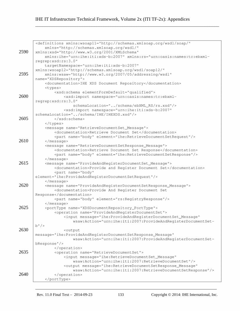
IHE IT Infrastructure Technical Framework, Volume 2x (ITI TF-2x): Appendices ______________________________________________________________________________
_____________________________________________________________________________ Rev. 11.0 Final Text – 2014-09-23 133 Copyright © 2014: IHE International, Inc.
<definitions xmlns:wsoap11="http://schemas.xmlsoap.org/wsdl/soap/" xmlns="http://schemas.xmlsoap.org/wsdl/" xmlns:xsd="http://www.w3.org/2001/XMLSchema" 2590 xmlns:ihe="urn:ihe:iti:xds-b:2007" xmlns:rs="urn:oasis:names:tc:ebxml-regrep:xsd:rs:3.0" targetNamespace="urn:ihe:iti:xds-b:2007" xmlns:wsoap12="http://schemas.xmlsoap.org/wsdl/soap12/" xmlns:wsaw="http://www.w3.org/2007/05/addressing/wsdl" 2595 name="XDSRepository"> <documentation>IHE XDS Document Repository</documentation> <types> <xsd:schema elementFormDefault="qualified"> <xsd:import namespace="urn:oasis:names:tc:ebxml-2600 regrep:xsd:rs:3.0" schemaLocation="../schema/ebXML_RS/rs.xsd"/> <xsd:import namespace="urn:ihe:iti:xds-b:2007" schemaLocation="../schema/IHE/IHEXDS.xsd"/> </xsd:schema> 2605 </types> <message name="RetrieveDocumentSet_Message"> <documentation>Retrieve Document Set</documentation> <part name="body" element="ihe:RetrieveDocumentSetRequest"/> </message> 2610 <message name="RetrieveDocumentSetResponse_Message"> <documentation>Retrieve Document Set Response</documentation> <part name="body" element="ihe:RetrieveDocumentSetResponse"/> </message> <message name="ProvideAndRegisterDocumentSet_Message"> 2615 <documentation>Provide and Register Document Set</documentation> <part name="body" element="ihe:ProvideAndRegisterDocumentSetRequest"/> </message> <message name="ProvideAndRegisterDocumentSetResponse_Message"> 2620 <documentation>Provide And Register Document Set Response</documentation> <part name="body" element="rs:RegistryResponse"/> </message> <portType name="XDSDocumentRepository_PortType"> 2625 <operation name="ProvideAndRegisterDocumentSet"> <input message="ihe:ProvideAndRegisterDocumentSet_Message" wsaw:Action="urn:ihe:iti:2007:ProvideAndRegisterDocumentSet-b"/> <output 2630 message="ihe:ProvideAndRegisterDocumentSetResponse_Message" wsaw:Action="urn:ihe:iti:2007:ProvideAndRegisterDocumentSet-bResponse"/> </operation> <operation name="RetrieveDocumentSet"> 2635 <input message="ihe:RetrieveDocumentSet_Message" wsaw:Action="urn:ihe:iti:2007:RetrieveDocumentSet"/> <output message="ihe:RetrieveDocumentSetResponse_Message" wsaw:Action="urn:ihe:iti:2007:RetrieveDocumentSetResponse"/> </operation> 2640 </portType>
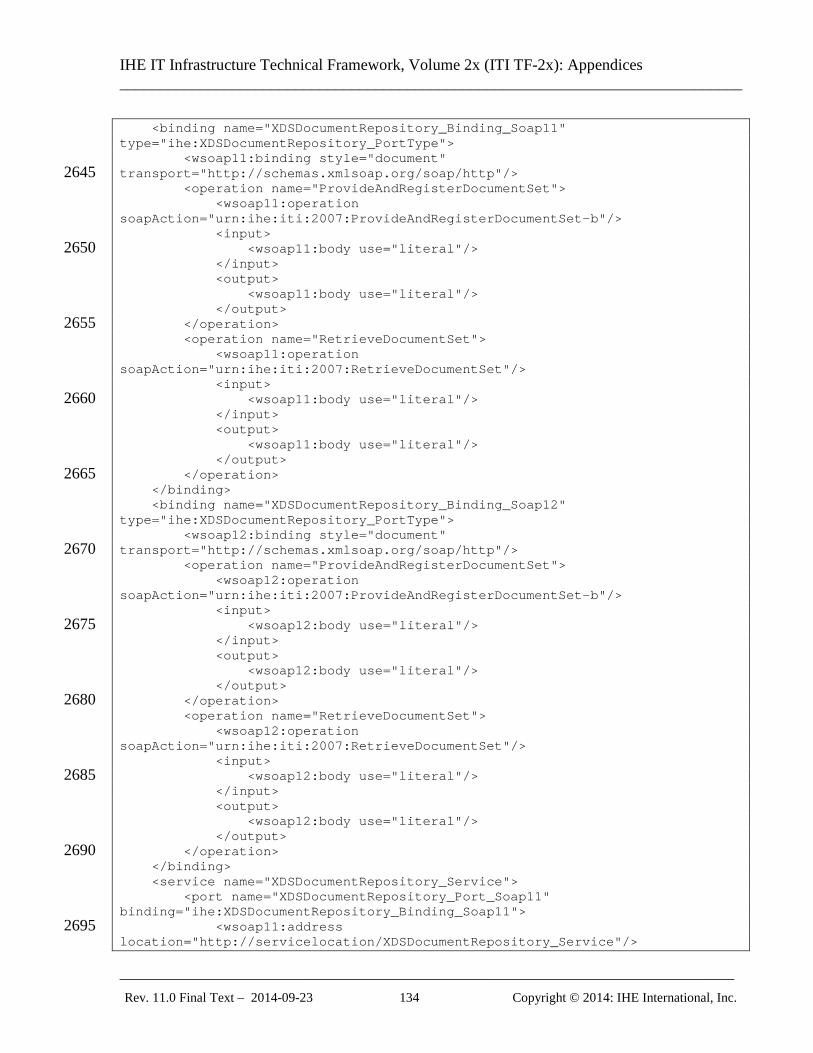
IHE IT Infrastructure Technical Framework, Volume 2x (ITI TF-2x): Appendices ______________________________________________________________________________
_____________________________________________________________________________ Rev. 11.0 Final Text – 2014-09-23 134 Copyright © 2014: IHE International, Inc.
<binding name="XDSDocumentRepository_Binding_Soap11" type="ihe:XDSDocumentRepository_PortType"> <wsoap11:binding style="document" transport="http://schemas.xmlsoap.org/soap/http"/> 2645 <operation name="ProvideAndRegisterDocumentSet"> <wsoap11:operation soapAction="urn:ihe:iti:2007:ProvideAndRegisterDocumentSet-b"/> <input> <wsoap11:body use="literal"/> 2650 </input> <output> <wsoap11:body use="literal"/> </output> </operation> 2655 <operation name="RetrieveDocumentSet"> <wsoap11:operation soapAction="urn:ihe:iti:2007:RetrieveDocumentSet"/> <input> <wsoap11:body use="literal"/> 2660 </input> <output> <wsoap11:body use="literal"/> </output> </operation> 2665 </binding> <binding name="XDSDocumentRepository_Binding_Soap12" type="ihe:XDSDocumentRepository_PortType"> <wsoap12:binding style="document" transport="http://schemas.xmlsoap.org/soap/http"/> 2670 <operation name="ProvideAndRegisterDocumentSet"> <wsoap12:operation soapAction="urn:ihe:iti:2007:ProvideAndRegisterDocumentSet-b"/> <input> <wsoap12:body use="literal"/> 2675 </input> <output> <wsoap12:body use="literal"/> </output> </operation> 2680 <operation name="RetrieveDocumentSet"> <wsoap12:operation soapAction="urn:ihe:iti:2007:RetrieveDocumentSet"/> <input> <wsoap12:body use="literal"/> 2685 </input> <output> <wsoap12:body use="literal"/> </output> </operation> 2690 </binding> <service name="XDSDocumentRepository_Service"> <port name="XDSDocumentRepository_Port_Soap11" binding="ihe:XDSDocumentRepository_Binding_Soap11"> <wsoap11:address 2695 location="http://servicelocation/XDSDocumentRepository_Service"/>
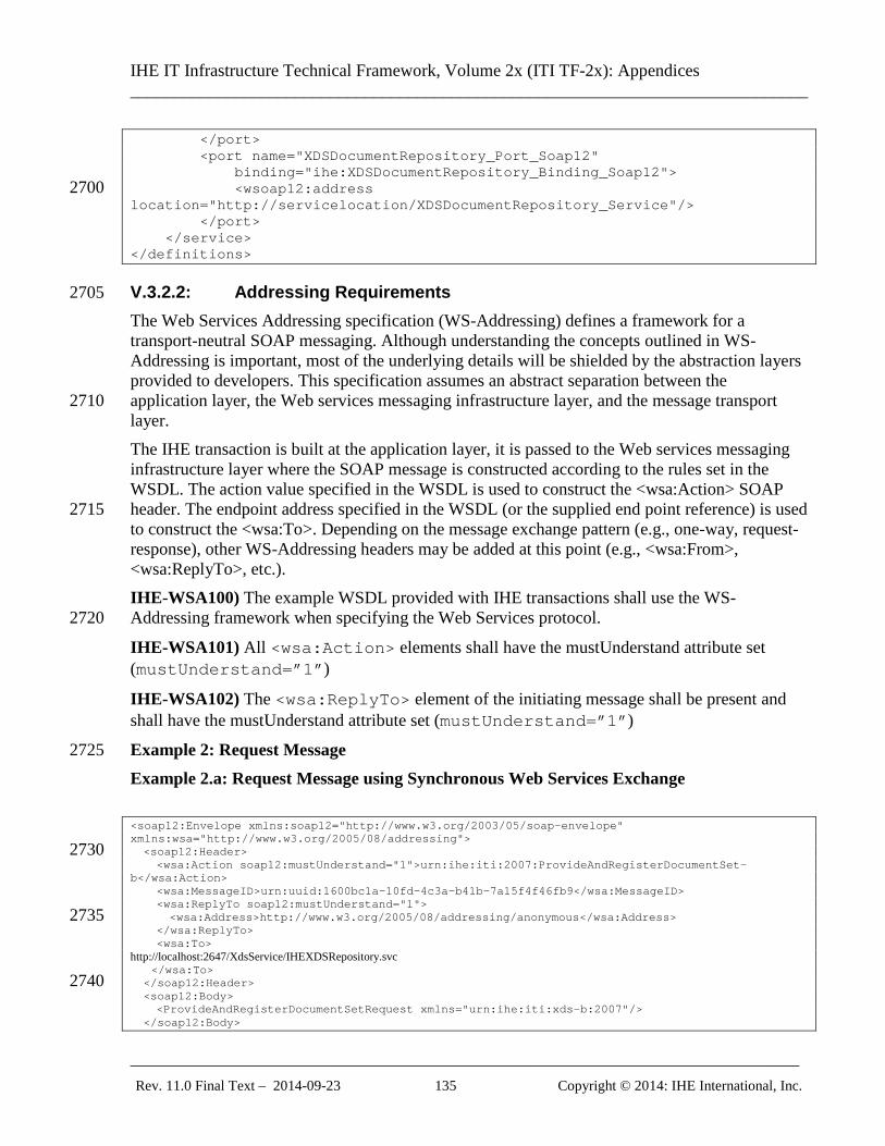
IHE IT Infrastructure Technical Framework, Volume 2x (ITI TF-2x): Appendices ______________________________________________________________________________
_____________________________________________________________________________ Rev. 11.0 Final Text – 2014-09-23 135 Copyright © 2014: IHE International, Inc.
</port> <port name="XDSDocumentRepository_Port_Soap12" binding="ihe:XDSDocumentRepository_Binding_Soap12"> <wsoap12:address 2700 location="http://servicelocation/XDSDocumentRepository_Service"/> </port> </service> </definitions>
V.3.2.2: Addressing Requirements 2705 The Web Services Addressing specification (WS-Addressing) defines a framework for a transport-neutral SOAP messaging. Although understanding the concepts outlined in WS-Addressing is important, most of the underlying details will be shielded by the abstraction layers provided to developers. This specification assumes an abstract separation between the application layer, the Web services messaging infrastructure layer, and the message transport 2710 layer. The IHE transaction is built at the application layer, it is passed to the Web services messaging infrastructure layer where the SOAP message is constructed according to the rules set in the WSDL. The action value specified in the WSDL is used to construct the <wsa:Action> SOAP header. The endpoint address specified in the WSDL (or the supplied end point reference) is used 2715 to construct the <wsa:To>. Depending on the message exchange pattern (e.g., one-way, request-response), other WS-Addressing headers may be added at this point (e.g., <wsa:From>, <wsa:ReplyTo>, etc.). IHE-WSA100) The example WSDL provided with IHE transactions shall use the WS-Addressing framework when specifying the Web Services protocol. 2720
IHE-WSA101) All <wsa:Action> elements shall have the mustUnderstand attribute set (mustUnderstand=”1”)
IHE-WSA102) The <wsa:ReplyTo> element of the initiating message shall be present and shall have the mustUnderstand attribute set (mustUnderstand=”1”)
Example 2: Request Message 2725 Example 2.a: Request Message using Synchronous Web Services Exchange <soap12:Envelope xmlns:soap12="http://www.w3.org/2003/05/soap-envelope" xmlns:wsa="http://www.w3.org/2005/08/addressing"> <soap12:Header> 2730 <wsa:Action soap12:mustUnderstand="1">urn:ihe:iti:2007:ProvideAndRegisterDocumentSet-b</wsa:Action> <wsa:MessageID>urn:uuid:1600bc1a-10fd-4c3a-b41b-7a15f4f46fb9</wsa:MessageID> <wsa:ReplyTo soap12:mustUnderstand="1"> <wsa:Address>http://www.w3.org/2005/08/addressing/anonymous</wsa:Address> 2735 </wsa:ReplyTo> <wsa:To> http://localhost:2647/XdsService/IHEXDSRepository.svc </wsa:To> </soap12:Header> 2740 <soap12:Body> <ProvideAndRegisterDocumentSetRequest xmlns="urn:ihe:iti:xds-b:2007"/> </soap12:Body>
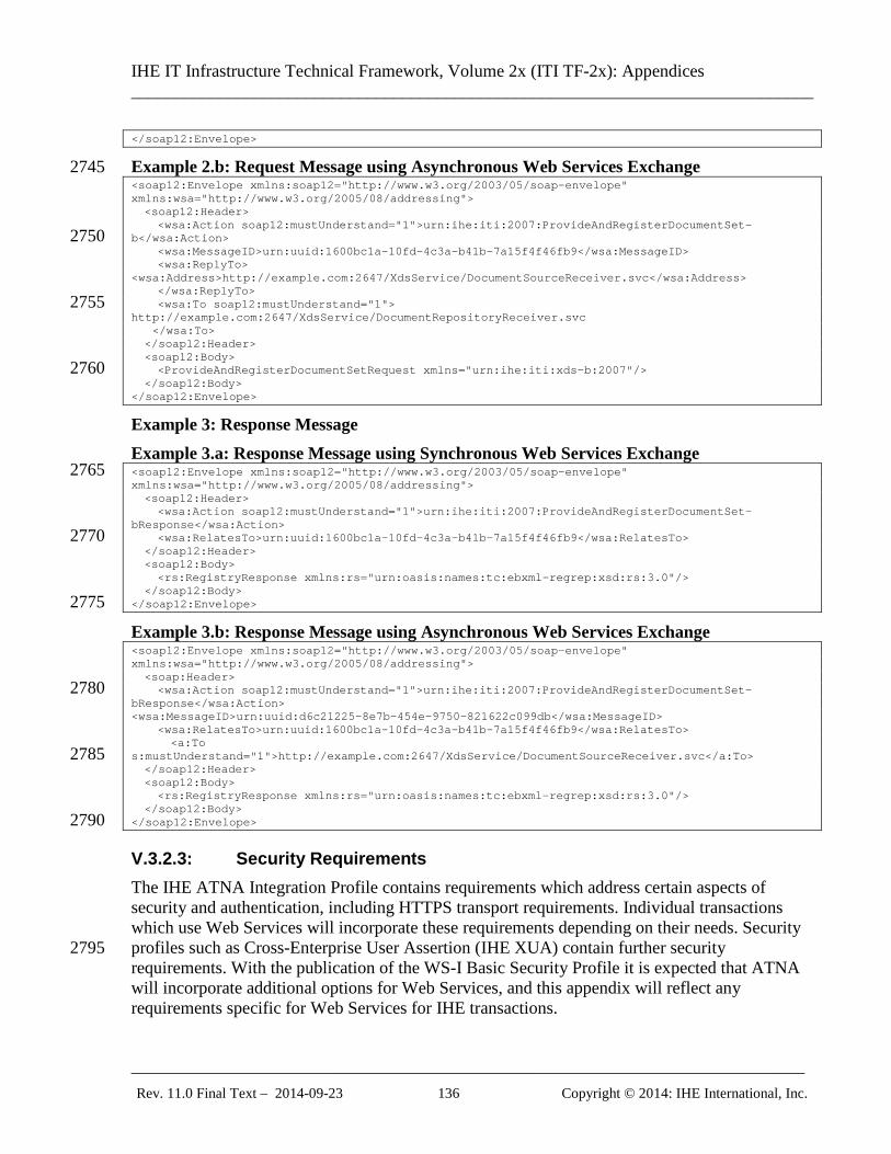
IHE IT Infrastructure Technical Framework, Volume 2x (ITI TF-2x): Appendices ______________________________________________________________________________
_____________________________________________________________________________ Rev. 11.0 Final Text – 2014-09-23 136 Copyright © 2014: IHE International, Inc.
</soap12:Envelope>
Example 2.b: Request Message using Asynchronous Web Services Exchange 2745 <soap12:Envelope xmlns:soap12="http://www.w3.org/2003/05/soap-envelope" xmlns:wsa="http://www.w3.org/2005/08/addressing"> <soap12:Header> <wsa:Action soap12:mustUnderstand="1">urn:ihe:iti:2007:ProvideAndRegisterDocumentSet-b</wsa:Action> 2750 <wsa:MessageID>urn:uuid:1600bc1a-10fd-4c3a-b41b-7a15f4f46fb9</wsa:MessageID> <wsa:ReplyTo> <wsa:Address>http://example.com:2647/XdsService/DocumentSourceReceiver.svc</wsa:Address> </wsa:ReplyTo> <wsa:To soap12:mustUnderstand="1"> 2755 http://example.com:2647/XdsService/DocumentRepositoryReceiver.svc </wsa:To> </soap12:Header> <soap12:Body> <ProvideAndRegisterDocumentSetRequest xmlns="urn:ihe:iti:xds-b:2007"/> 2760 </soap12:Body> </soap12:Envelope>
Example 3: Response Message Example 3.a: Response Message using Synchronous Web Services Exchange <soap12:Envelope xmlns:soap12="http://www.w3.org/2003/05/soap-envelope" 2765 xmlns:wsa="http://www.w3.org/2005/08/addressing"> <soap12:Header> <wsa:Action soap12:mustUnderstand="1">urn:ihe:iti:2007:ProvideAndRegisterDocumentSet-bResponse</wsa:Action> <wsa:RelatesTo>urn:uuid:1600bc1a-10fd-4c3a-b41b-7a15f4f46fb9</wsa:RelatesTo> 2770 </soap12:Header> <soap12:Body> <rs:RegistryResponse xmlns:rs="urn:oasis:names:tc:ebxml-regrep:xsd:rs:3.0"/> </soap12:Body> </soap12:Envelope> 2775
Example 3.b: Response Message using Asynchronous Web Services Exchange <soap12:Envelope xmlns:soap12="http://www.w3.org/2003/05/soap-envelope" xmlns:wsa="http://www.w3.org/2005/08/addressing"> <soap:Header> <wsa:Action soap12:mustUnderstand="1">urn:ihe:iti:2007:ProvideAndRegisterDocumentSet-2780 bResponse</wsa:Action> <wsa:MessageID>urn:uuid:d6c21225-8e7b-454e-9750-821622c099db</wsa:MessageID> <wsa:RelatesTo>urn:uuid:1600bc1a-10fd-4c3a-b41b-7a15f4f46fb9</wsa:RelatesTo> <a:To s:mustUnderstand="1">http://example.com:2647/XdsService/DocumentSourceReceiver.svc</a:To> 2785 </soap12:Header> <soap12:Body> <rs:RegistryResponse xmlns:rs="urn:oasis:names:tc:ebxml-regrep:xsd:rs:3.0"/> </soap12:Body> </soap12:Envelope> 2790
V.3.2.3: Security Requirements The IHE ATNA Integration Profile contains requirements which address certain aspects of security and authentication, including HTTPS transport requirements. Individual transactions which use Web Services will incorporate these requirements depending on their needs. Security profiles such as Cross-Enterprise User Assertion (IHE XUA) contain further security 2795 requirements. With the publication of the WS-I Basic Security Profile it is expected that ATNA will incorporate additional options for Web Services, and this appendix will reflect any requirements specific for Web Services for IHE transactions.
IHE IT Infrastructure Technical Framework, Volume 2x (ITI TF-2x): Appendices ______________________________________________________________________________
_____________________________________________________________________________ Rev. 11.0 Final Text – 2014-09-23 137 Copyright © 2014: IHE International, Inc.
V.4: Web Services for specific IHE Transactions The Web Services specification is provided in three parts. The first part will be in Volumes 2a, 2800 2b and 2c, where a separate subsection shall be added for each affected IHE transaction at the end of the “Message Semantics” section. This subsection shall detail the types and message parts of the WSDL. The actor-specific constraints against the IHE Web Services Requirements specified above shall be added at the end of each “Expected Actions” section. The second, informative part of the specification shall be on the IHE ftp site (See ITI TF-2x: 2805 Appendix W), which shall contain a complete WSDL (Web Services Description Language) description of the web service, which aggregates the snippets from Volumes 2a, 2b and 2c described above. There will be one WSDL contract per actor per profile. Each transaction is represented by a port type, where the operations names and message names follow the requirements specified in ITI TF-2x: V.3.2.1.1. The complete WSDL is for reference purposes 2810 for implementers.
V.5: Synchronous and Asynchronous Web Services Exchange
V.5.1: Overview When two actors, later referred to as Requestor and Provider, need to exchange web services messages using a request-response message exchange pattern, they can do so synchronously or 2815 asynchronously. With synchronous message exchange, the Requestor sends a request and blocks waiting for a response from the Provider. The Requestor receives the response on the same connection that the Requestor initially established to send the request. Synchronous exchange is usually easier to implement and requires that the Provider be available when the Requestor needs to send a 2820 request. With asynchronous message exchange, the Requestor is only concerned with sending the request, knowing that it will ‘eventually’ receive a response. The Provider may not be available at the time the request is sent. When the Provider receives and processes the message it sends a response back to the Requestor over a new connection. Asynchronous Web Services Exchange 2825 enables support for network infrastructures where:
• Transports are unreliable
• Systems are not always available
• Variable or high communication latency is present Asynchronous Web Services Exchange opens the option for using intermediaries for store and 2830 forward or offline communication modes, and leveraging reliable messaging mechanisms to address the reliability and availability challenges that these types of network infrastructures present. Asynchronous Web Services Exchange enables support for clinical use cases that can benefit from asynchronous infrastructure capabilities such as offline mode.
V.5.2: Considerations for using Asynchronous Web Services Exchange 2835
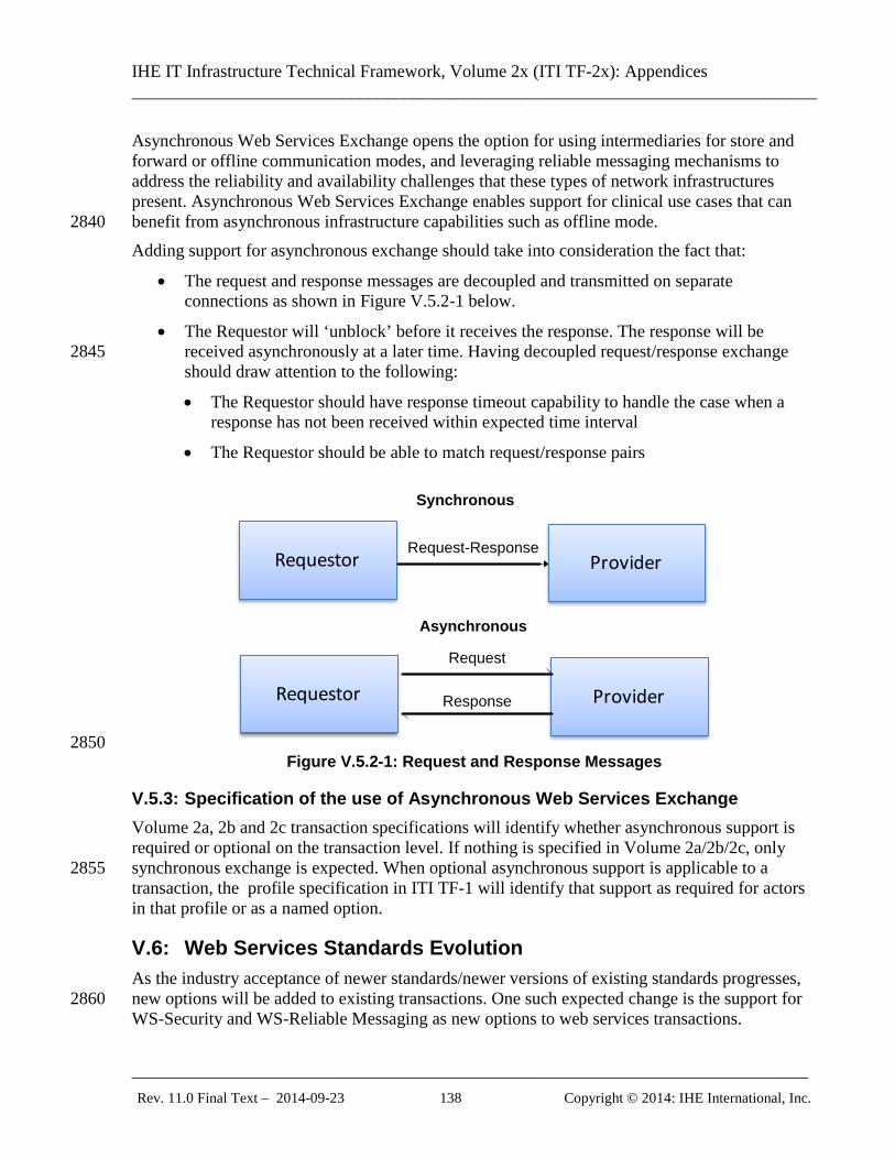
IHE IT Infrastructure Technical Framework, Volume 2x (ITI TF-2x): Appendices ______________________________________________________________________________
_____________________________________________________________________________ Rev. 11.0 Final Text – 2014-09-23 138 Copyright © 2014: IHE International, Inc.
Asynchronous Web Services Exchange opens the option for using intermediaries for store and forward or offline communication modes, and leveraging reliable messaging mechanisms to address the reliability and availability challenges that these types of network infrastructures present. Asynchronous Web Services Exchange enables support for clinical use cases that can benefit from asynchronous infrastructure capabilities such as offline mode. 2840 Adding support for asynchronous exchange should take into consideration the fact that:
• The request and response messages are decoupled and transmitted on separate connections as shown in Figure V.5.2-1 below.
• The Requestor will ‘unblock’ before it receives the response. The response will be received asynchronously at a later time. Having decoupled request/response exchange 2845 should draw attention to the following:
• The Requestor should have response timeout capability to handle the case when a response has not been received within expected time interval
• The Requestor should be able to match request/response pairs
2850 Figure V.5.2-1: Request and Response Messages
V.5.3: Specification of the use of Asynchronous Web Services Exchange Volume 2a, 2b and 2c transaction specifications will identify whether asynchronous support is required or optional on the transaction level. If nothing is specified in Volume 2a/2b/2c, only synchronous exchange is expected. When optional asynchronous support is applicable to a 2855 transaction, the profile specification in ITI TF-1 will identify that support as required for actors in that profile or as a named option.
V.6: Web Services Standards Evolution As the industry acceptance of newer standards/newer versions of existing standards progresses, new options will be added to existing transactions. One such expected change is the support for 2860 WS-Security and WS-Reliable Messaging as new options to web services transactions.
Requestor ProviderRequest-Response
Requestor Provider
Synchronous
Asynchronous
Request
Response
IHE IT Infrastructure Technical Framework, Volume 2x (ITI TF-2x): Appendices ______________________________________________________________________________
_____________________________________________________________________________ Rev. 11.0 Final Text – 2014-09-23 139 Copyright © 2014: IHE International, Inc.
V.7: Web Services References WS-I: http://ws-i.org/ WS-I Basic Profile 1.2: http://ws-i.org/Profiles/BasicProfile-1.2-2010-11-09.html WS-I Basic Profile 2.0: http://ws-i.org/Profiles/BasicProfile-2.0-2010-11-09.html 2865 SOAP 1.1: http://www.w3.org/TR/2000/NOTE-SOAP-20000508/ SOAP 1.2: http://www.w3.org/TR/soap12-part0/ WSDL 1.1 SOAP 1.1 binding (Chapter 3): http://www.w3.org/TR/wsdl.html#_soap-b WSDL 1.1 SOAP 1.2 binding: http://www.w3.org/Submission/wsdl11soap12/ HL7 V3 Web Services Profile: 2870 http://www.hl7.org/v3ballot/html/infrastructure/transport/transport-wsprofiles.htm WS-Addressing: http://www.w3.org/TR/ws-addr-core WS-I Basic Security Profile 1.1: http://www.ws-i.org/Profiles/BasicSecurityProfile-1.1.html WS-I Reliable Secure Profile: http://www.ws-i.org/Profiles/ReliableSecureProfile-1.0-2010-11-09.html 2875 MTOM: http://www.w3.org/TR/soap12-mtom/ XOP: http://www.w3.org/TR/xop10/ WS-Security 1.0: http://www.oasis-open.org/committees/tc_home.php?wg_abbrev=wss#technical WS-Security 1.1: http://www.oasis-2880 open.org/committees/tc_home.php?wg_abbrev=wss#technical WS-Secure Conversation: http://docs.oasis-open.org/ws-sx/ws-secureconversation/v1.4/ws-secureconversation.html WS-Trust: http://docs.oasis-open.org/ws-sx/ws-trust/v1.4/errata01/os/ws-trust-1.4-errata01-os-complete.html 2885 WS-Policy: http://www.w3.org/TR/ws-policy/ WS-Reliable Messaging: http://docs.oasis-open.org/ws-rx/wsrm/200702
IHE IT Infrastructure Technical Framework, Volume 2x (ITI TF-2x): Appendices ______________________________________________________________________________
_____________________________________________________________________________ Rev. 11.0 Final Text – 2014-09-23 140 Copyright © 2014: IHE International, Inc.
Appendix W: Implementation Material Implementation material for ITI profiles such as XDS, XCA, RFD, and others can be found on the IHE FTP site under ftp://ftp.ihe.net/TF_Implementation_Material/ITI/. 2890 Some of the types of implementation material available are schema, examples and informative WSDL.
IHE IT Infrastructure Technical Framework, Volume 2x (ITI TF-2x): Appendices ______________________________________________________________________________
_____________________________________________________________________________ Rev. 11.0 Final Text – 2014-09-23 141 Copyright © 2014: IHE International, Inc.
GLOSSARY See IHE ITI TF-1: Glossary. 2895


![IHE IT Infrastructure Technical Framework Volume 2a (ITI TF ......2019/07/12 · 215 • Volume 2b: Sections 3.29 - 3.64 corresponding to transactions [ITI-29] through [ITI-64]. Volume](https://img.pdfslide.us/doc/110x75/5ff2d3208e04d64ca9163d5f/ihe-it-infrastructure-technical-framework-volume-2a-iti-tf-20190712-.jpg)