Embed Size (px)
Citation preview

</IGS3 Testing Notes.doc/bö - page 1
IGS MINI-LECTURE
Testing of GEOSYNTHETICS
Prof. Dr.-Ing. Müller-Rochholz, Fachhochschule Münster andtBU - Institut für textile Bau- und Umwelttechnik GmbH, Greven
Content
1. General product identification1.1 Polymer identification1.2 Geometrical information 1.2.1 Thickness 1.2.2 Grid opening/pitch1.3 Mass per unit area
2. Mechanical properties2.1 Short-term tensile strength and dependent deformation2.2 Long-term tensile behaviour (creep/creep rupture)2.3 Long-term compressive creep behaviour (with/without shear stress)2.4 Resistance against impact or punching 2.4.1 Static puncture test 2.4.2 Rapid puncture2.5 Resistance against abrasion2.6 Friction properties 2.6.1 Direct shear 2.6.2 Inclined plane test 2.6.3 Pullout resistance2.7 Protection efficiency2.8 Damage during installation2.9 Geosynthetics or composites internal strength
3. Hydraulic properties3.1 Water permeability characteristics normal to plane, without load 3.1.1 Constant head 3.1.2 Falling head3.2 Water flow capacity in their plane3.3 Characteristic opening size
4. Durability properties4.1 Resistance to weathering4.2 Resistance to microbiological degradation (soil burial)4.3 Resistance to liquids 4.3.1 Resistance to hydrolysis 4.3.2 Resistance to thermal oxidation
</IGS3 Testing Notes.doc/bö - page 2
1 General product identification
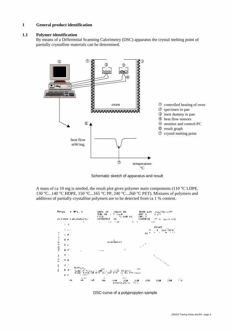
1.1 Polymer identificationBy means of a Differential Scanning Calorimetry (DSC) apparatus the crystal melting point ofpartially crystalline materials can be determined.
A mass of ca 10 mg is needed, the result plot gives polymer main components (110 °C LDPE,130 °C...140 °C HDPE, 150 °C...165 °C PP, 240 °C...260 °C PET). Mixtures of polymers andadditives of partially crystalline polymers are to be detected from ca 1 % content.
Schematic sketch of apparatus and result
DSC-curve of a polypropylen sample
ú
oven
� �ì ó
ö
÷
heat flowmW/mg
temperature°C
� controlled heating of ovenó specimen in panì inert dummy in panö heat flow sensorsú monitor and control-PC÷ result graphø crystal melting point
ø
</IGS3 Testing Notes.doc/bö - page 3
1.2 Geometrical Information
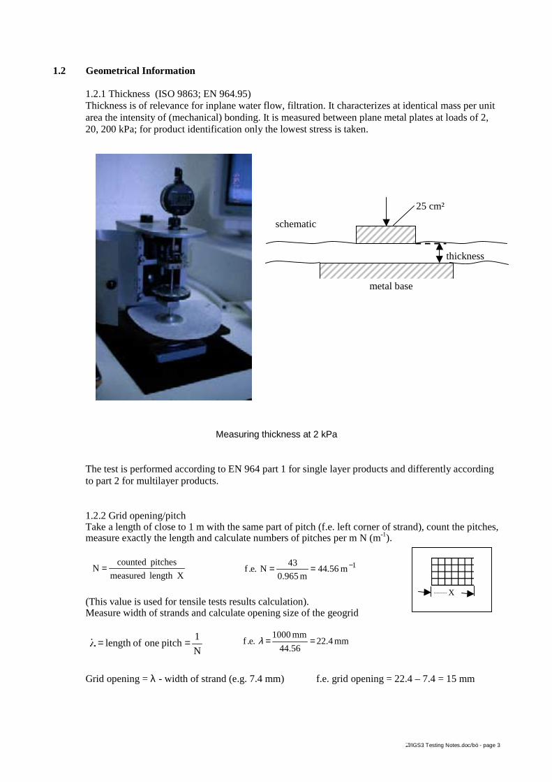
1.2.1 Thickness (ISO 9863; EN 964.95)Thickness is of relevance for inplane water flow, filtration. It characterizes at identical mass per unitarea the intensity of (mechanical) bonding. It is measured between plane metal plates at loads of 2,20, 200 kPa; for product identification only the lowest stress is taken.
Measuring thickness at 2 kPa
The test is performed according to EN 964 part 1 for single layer products and differently accordingto part 2 for multilayer products.
1.2.2 Grid opening/pitchTake a length of close to 1 m with the same part of pitch (f.e. left corner of strand), count the pitches,measure exactly the length and calculate numbers of pitches per m N (m-1).
(This value is used for tensile tests results calculation).Measure width of strands and calculate opening size of the geogrid
Grid opening = λ - width of strand (e.g. 7.4 mm) f.e. grid opening = 22.4 – 7.4 = 15 mm
Xlength measured
pitches countedN = 1m 56.44
m 965.0
43N.e.f −==
N
1pitch one oflength ==
X
mm4.2256.44
mm1000.e.f ==λ
schematic
25 cm²
thickness
metal base
</IGS3 Testing Notes.doc/bö - page 4
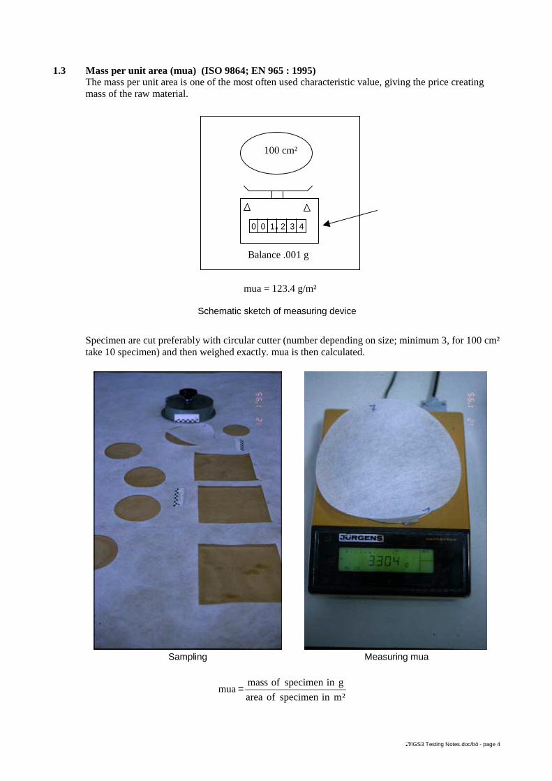
1.3 Mass per unit area (mua) (ISO 9864; EN 965 : 1995)The mass per unit area is one of the most often used characteristic value, giving the price creatingmass of the raw material.
Specimen are cut preferably with circular cutter (number depending on size; minimum 3, for 100 cm²take 10 specimen) and then weighed exactly. mua is then calculated.
Sampling Measuring mua
100 cm²
0 0 1. 2 3 4
Balance .001 g
mua = 123.4 g/m²
²minspecimenofarea
ginspecimenofmassmua =
Schematic sketch of measuring device
</IGS3 Testing Notes.doc/bö - page 5
2 Mechanical properties
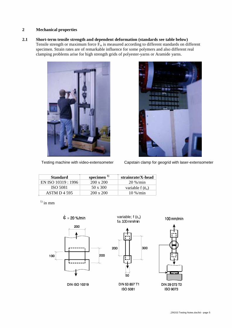
2.1 Short-term tensile strength and dependent deformation (standards see table below)Tensile strength or maximum force Fm is measured according to different standards on differentspecimen. Strain rates are of remarkable influence for some polymers and also different realclamping problems arise for high strength grids of polyester-yarns or Aramide yarns.
Testing machine with video-extensometer Capstain clamp for geogrid with laser-extensometer
Standard specimen 1) strainrate/X-headEN ISO 10319 : 1996 200 x 200 20 %/min
ISO 5081 50 x 300 variable f (εu)ASTM D 4 595 200 x 200 10 %/min
1) in mm
ε�variable; f (εu)f.e. 100 mm/min
</IGS3 Testing Notes.doc/bö - page 6
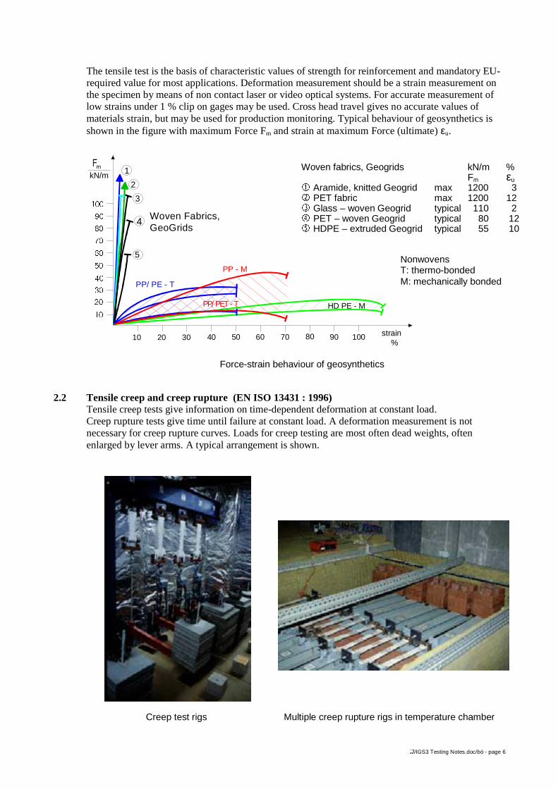
The tensile test is the basis of characteristic values of strength for reinforcement and mandatory EU-required value for most applications. Deformation measurement should be a strain measurement onthe specimen by means of non contact laser or video optical systems. For accurate measurement oflow strains under 1 % clip on gages may be used. Cross head travel gives no accurate values ofmaterials strain, but may be used for production monitoring. Typical behaviour of geosynthetics isshown in the figure with maximum Force Fm and strain at maximum Force (ultimate) εu.
Force-strain behaviour of geosynthetics
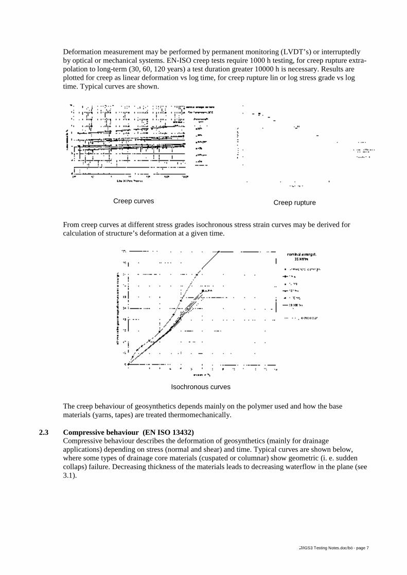
2.2 Tensile creep and creep rupture (EN ISO 13431 : 1996)Tensile creep tests give information on time-dependent deformation at constant load.Creep rupture tests give time until failure at constant load. A deformation measurement is notnecessary for creep rupture curves. Loads for creep testing are most often dead weights, oftenenlarged by lever arms. A typical arrangement is shown.
Creep test rigs Multiple creep rupture rigs in temperature chamber
HD PE - M
PP/ PE - T
PP - M
PP/ PET - T
Woven Fabrics, GeoGrids
10 20 30 40 50 60 70 80 90 100 strain%
��
��
��
��
��
��
��
��
��
���
m
kN/m 1
2
3
4
5
Woven fabrics, Geogrids kN/m %Fm εu
� Aramide, knitted Geogrid max 1200 3ó PET fabric max 1200 12ì Glass – woven Geogrid typical 110 2ö PET – woven Geogrid typical 80 12ú HDPE – extruded Geogrid typical 55 10
NonwovensT: thermo-bondedM: mechanically bonded
</IGS3 Testing Notes.doc/bö - page 7
Deformation measurement may be performed by permanent monitoring (LVDT’s) or interruptedlyby optical or mechanical systems. EN-ISO creep tests require 1000 h testing, for creep rupture extra-polation to long-term (30, 60, 120 years) a test duration greater 10000 h is necessary. Results areplotted for creep as linear deformation vs log time, for creep rupture lin or log stress grade vs logtime. Typical curves are shown.
From creep curves at different stress grades isochronous stress strain curves may be derived forcalculation of structure’s deformation at a given time.
The creep behaviour of geosynthetics depends mainly on the polymer used and how the basematerials (yarns, tapes) are treated thermomechanically.
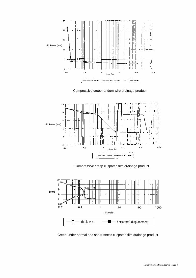
2.3 Compressive behaviour (EN ISO 13432)Compressive behaviour describes the deformation of geosynthetics (mainly for drainageapplications) depending on stress (normal and shear) and time. Typical curves are shown below,where some types of drainage core materials (cuspated or columnar) show geometric (i. e. suddencollaps) failure. Decreasing thickness of the materials leads to decreasing waterflow in the plane (see3.1).
Creep ruptureCreep curves
Isochronous curves
</IGS3 Testing Notes.doc/bö - page 8
thickness (mm)
time (h)
Compressive creep cuspated film drainage product
time (h)
thickness horizontal displacement
Creep under normal and shear stress cuspated film drainage product
thickness (mm)
time /h)
Compressive creep random wire drainage product
</IGS3 Testing Notes.doc/bö - page 9
2.4 Resistance against punctureMineral cover material is dropped during installation of geosynthetics on the fabric, than spread andcompacted by vibration and heavy static loads. During these construction elements mineral materialshall not puncture the geosynthetic applied as separator or filter. Different tests reflect the differentelements.
2.4.1 Static puncture test
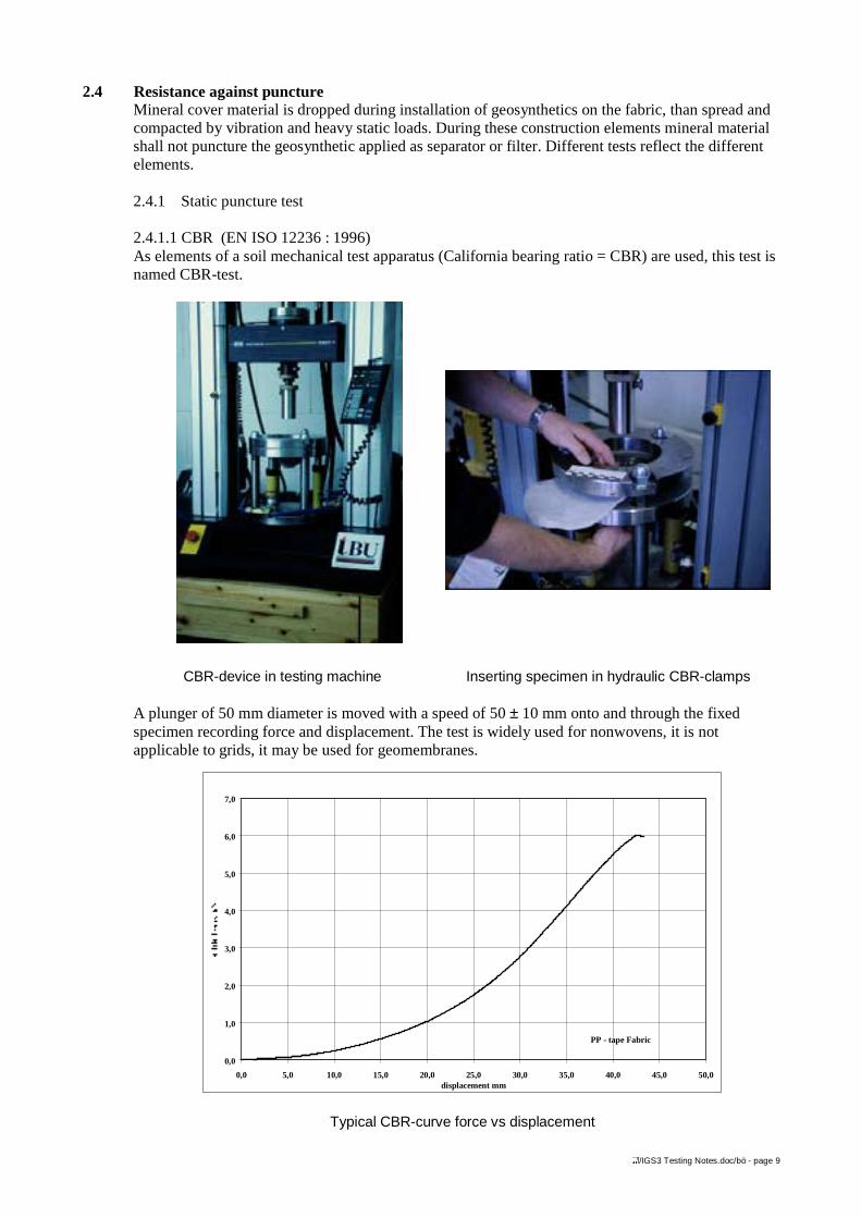
2.4.1.1 CBR (EN ISO 12236 : 1996)As elements of a soil mechanical test apparatus (California bearing ratio = CBR) are used, this test isnamed CBR-test.
CBR-device in testing machine Inserting specimen in hydraulic CBR-clamps
A plunger of 50 mm diameter is moved with a speed of 50 ± 10 mm onto and through the fixedspecimen recording force and displacement. The test is widely used for nonwovens, it is notapplicable to grids, it may be used for geomembranes.
0,0
1,0
2,0
3,0
4,0
5,0
6,0
7,0
0,0 5,0 10,0 15,0 20,0 25,0 30,0 35,0 40,0 45,0 50,0displacement mm
PP - tape Fabric
Typical CBR-curve force vs displacement
</IGS3 Testing Notes.doc/bö - page 10
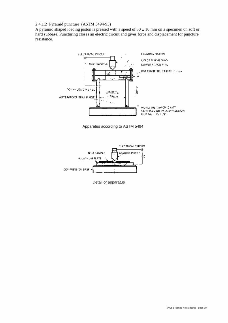
2.4.1.2 Pyramid puncture (ASTM 5494-93)A pyramid shaped loading piston is pressed with a speed of 50 ± 10 mm on a specimen on soft orhard subbase. Puncturing closes an electric circuit and gives force and displacement for punctureresistance.
Apparatus according to ASTM 5494
Detail of apparatus
</IGS3 Testing Notes.doc/bö - page 11
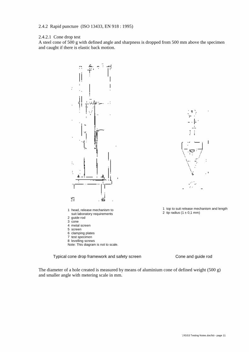
2.4.2 Rapid puncture (ISO 13433, EN 918 : 1995)
2.4.2.1 Cone drop testA steel cone of 500 g with defined angle and sharpness is dropped from 500 mm above the specimenand caught if there is elastic back motion.
The diameter of a hole created is measured by means of aluminium cone of defined weight (500 g)and smaller angle with metering scale in mm.
1 head, release mechanism to suit laboratory requirements2 guide rod3 cone4 metal screen5 screen6 clamping plates7 test specimen8 levelling screwsNote: This diagram is not to scale.
1 top to suit release mechanism and length2 tip radius (1 ± 0,1 mm)
Typical cone drop framework and safety screen Cone and guide rod
</IGS3 Testing Notes.doc/bö - page 12
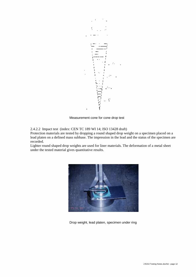
2.4.2.2 Impact test (index: CEN TC 189 WI 14; ISO 13428 draft)Protection materials are tested by dropping a round shaped drop weight on a specimen placed on alead platen on a defined mass subbase. The impression in the lead and the status of the specimen arerecorded.Lighter round shaped drop weights are used for liner materials. The deformation of a metal sheetunder the tested material gives quantitative results.
Measurement cone for cone drop test
Drop weight, lead platen, specimen under ring
</IGS3 Testing Notes.doc/bö - page 13
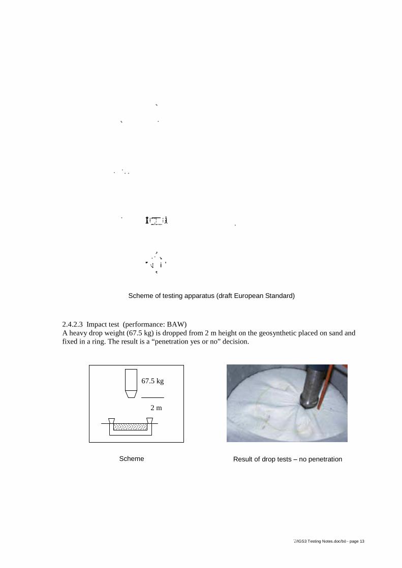
2.4.2.3 Impact test (performance: BAW)A heavy drop weight (67.5 kg) is dropped from 2 m height on the geosynthetic placed on sand andfixed in a ring. The result is a “penetration yes or no” decision.
Scheme of testing apparatus (draft European Standard)
2 m
67.5 kg
Scheme Result of drop tests – no penetration
</IGS3 Testing Notes.doc/bö - page 14
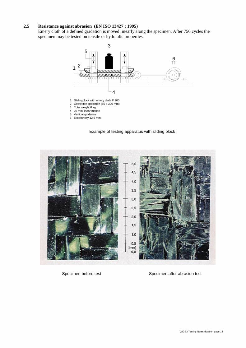
2.5 Resistance against abrasion (EN ISO 13427 : 1995)Emery cloth of a defined gradation is moved linearly along the specimen. After 750 cycles thespecimen may be tested on tensile or hydraulic properties.
Example of testing apparatus with sliding block
1 Slidingblock with emery cloth P 1002 Geotextile specimen (50 x 300 mm)3 Total weight 6 kg4 25 mm linear motion5 Vertical guidance6 Excentricity 12.5 mm
4
35
21
6
Specimen before test Specimen after abrasion test
</IGS3 Testing Notes.doc/bö - page 15
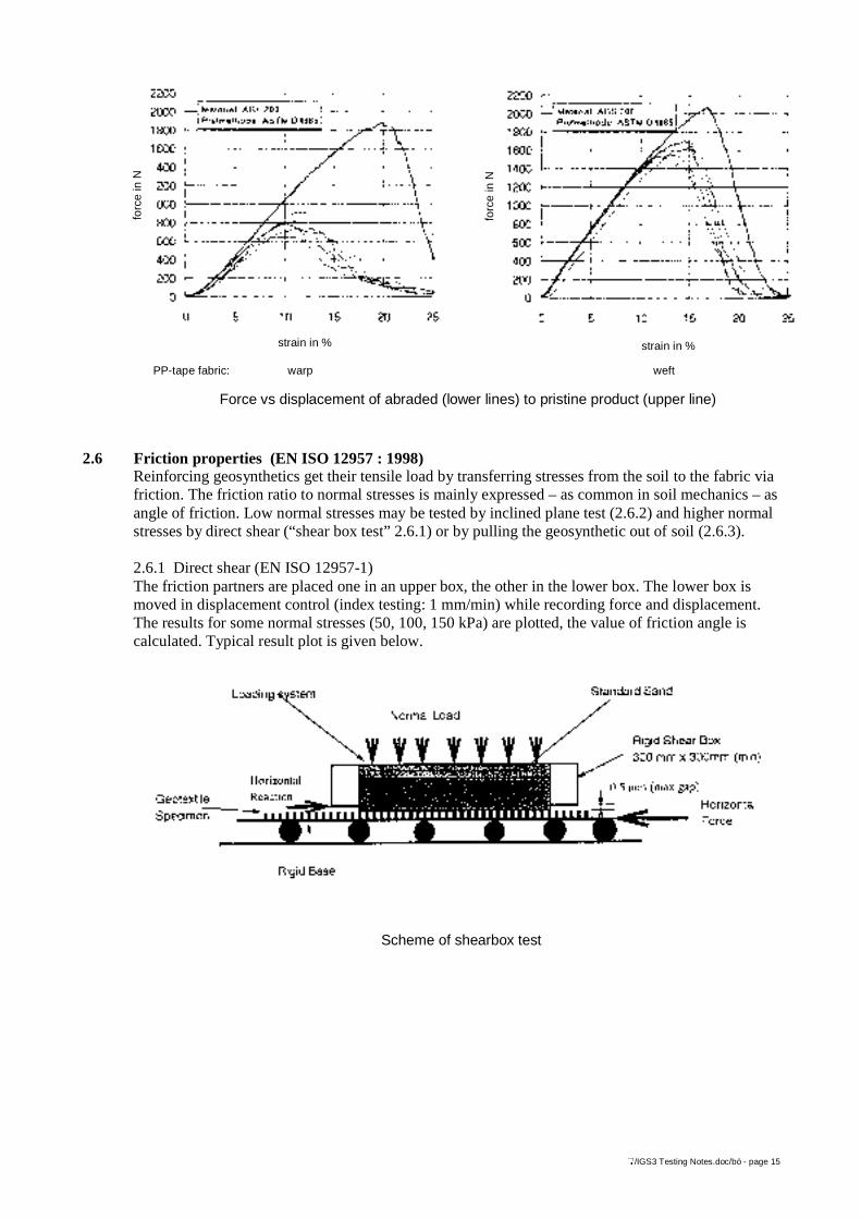
2.6 Friction properties (EN ISO 12957 : 1998)Reinforcing geosynthetics get their tensile load by transferring stresses from the soil to the fabric viafriction. The friction ratio to normal stresses is mainly expressed – as common in soil mechanics – asangle of friction. Low normal stresses may be tested by inclined plane test (2.6.2) and higher normalstresses by direct shear (“shear box test” 2.6.1) or by pulling the geosynthetic out of soil (2.6.3).
2.6.1 Direct shear (EN ISO 12957-1)The friction partners are placed one in an upper box, the other in the lower box. The lower box ismoved in displacement control (index testing: 1 mm/min) while recording force and displacement.The results for some normal stresses (50, 100, 150 kPa) are plotted, the value of friction angle iscalculated. Typical result plot is given below.
forc
e in
N
strain in %
forc
e in
N
strain in %
PP-tape fabric: warp weft
Force vs displacement of abraded (lower lines) to pristine product (upper line)
Scheme of shearbox test
</IGS3 Testing Notes.doc/bö - page 16
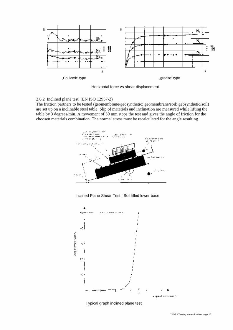
2.6.2 Inclined plane test (EN ISO 12957-2)The friction partners to be tested (geomembrane/geosynthetic; geomembrane/soil; geosynthetic/soil)are set up on a inclinable steel table. Slip of materials and inclination are measured while lifting thetable by 3 degrees/min. A movement of 50 mm stops the test and gives the angle of friction for thechoosen materials combination. The normal stress must be recalculated for the angle resulting.
Inclined Plane Shear Test : Soil filled lower base
Typical graph inclined plane test
„Coulomb“ type „grease“ type
Horizontal force vs shear displacement
s s
H H
N3
N2
N1
N3
N2
N1
</IGS3 Testing Notes.doc/bö - page 17
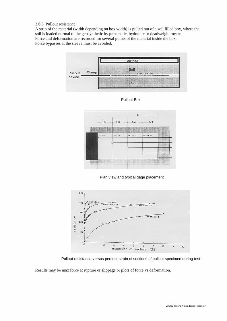
2.6.3 Pullout resistanceA strip of the material (width depending on box width) is pulled out of a soil filled box, where thesoil is loaded normal to the geosynthetic by pneumatic, hydraulic or deadweight means.Force and deformation are recorded for several points of the material inside the box.Force bypasses at the sleeve must be avoided.
Results may be max force at rupture or slippage or plots of force vs deformation.
Pullout Box
Pullout resistance versus percent strain of sections of pullout specimen during test
Plan view and typical gage placement
</IGS3 Testing Notes.doc/bö - page 18
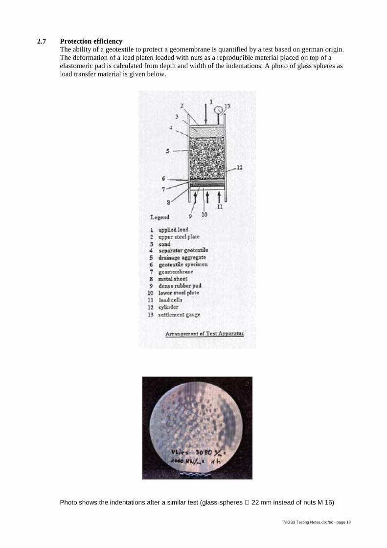
2.7 Protection efficiencyThe ability of a geotextile to protect a geomembrane is quantified by a test based on german origin.The deformation of a lead platen loaded with nuts as a reproducible material placed on top of aelastomeric pad is calculated from depth and width of the indentations. A photo of glass spheres asload transfer material is given below.
Photo shows the indentations after a similar test (glass-spheres ∅ 22 mm instead of nuts M 16)
</IGS3 Testing Notes.doc/bö - page 19
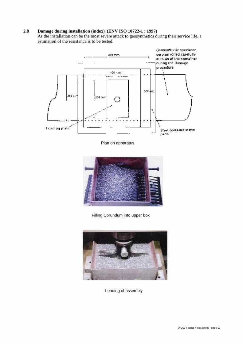
2.8 Damage during installation (index) (ENV ISO 10722-1 : 1997)As the installation can be the most severe attack to geosynthetics during their service life, aestimation of the resistance is to be tested.
Plan on apparatus
Filling Corundum into upper box
Loading of assembly

</IGS3 Testing Notes.doc/bö - page 20
The CEN-ISO standard applies a cyclic load on a platen (100 x 200) pressing via a layer ofcorundum aggregat the geosynthetic to be tested.After 200 cycles between 5 kPa and 900 kPa maximum stress the specimen is exhumed and may betested for reinforcement on residual strength, for filtration on hydraulic properties. A performancetest requires the soil and fill of the site and the equipment to spread and compact the material.Results of the index-test are given below.
2.9 Geosynthetics or composites internal strength (EN ISO 13426-1)If a failure of internal junctions may cause failure of a structure, the strength of these junctions shallbe tested. CEN WG 3 has 3 parts in progress.
2.9.1 GeocellsThe loading of a internal geocell-connection may be of a tensile shear type
a peeling typea splitting type
or of combinations.A typical test scheme for split test is given:
The parts geocomposites and geogrids are in working group discussion.
Material before (left) and after (right) damage test
</IGS3 Testing Notes.doc/bö - page 21
3 Hydraulic properties
3.1 Water permeability characteristics normal to the plane, without load (EN ISO 11058 : 1999)When geosynthetics are working as filters, water shall pass the filter and soil shall only pass in grainsizes to create a stable secondary filter in the contact soil zone.The water flow may be determined at stationary (time independent) conditions i.e. constant flow atconstant water head or at instationary conditions, i.e. “falling head”.
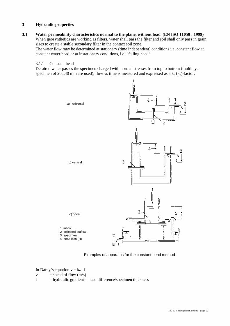
3.1.1 Constant headDe-aired water passes the specimen charged with normal stresses from top to bottom (multilayerspecimen of 20...40 mm are used), flow vs time is measured and expressed as a kv (kn)-factor.
In Darcy’s equation v = kv ⋅ iv = speed of flow (m/s)i = hydraulic gradient = head difference/specimen thickness
Beispiele von Prüfgeräten für das Verfahren mit konstanter Druckhöhe
a) horizontal
b) vertical
c) open
1 inflow2 collected outflow3 specimen4 head loss (H)
Examples of apparatus for the constant head method
</IGS3 Testing Notes.doc/bö - page 22
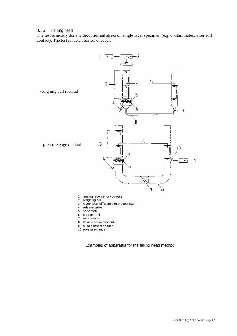
3.1.2 Falling headThe test is mostly done without normal stress on single layer specimen (e.g. contaminated, after soilcontact). The test is faster, easier, cheeper.
Examples of apparatus for the falling head method
weighing cell method
pressure gage method
1 analog recorder or computer2 weighing cell3 water level difference at the test start4 release valve5 specimen6 support grid7 main valve8 flexible connection tube9 fixed connection tube10 pressure gauge
</IGS3 Testing Notes.doc/bö - page 23
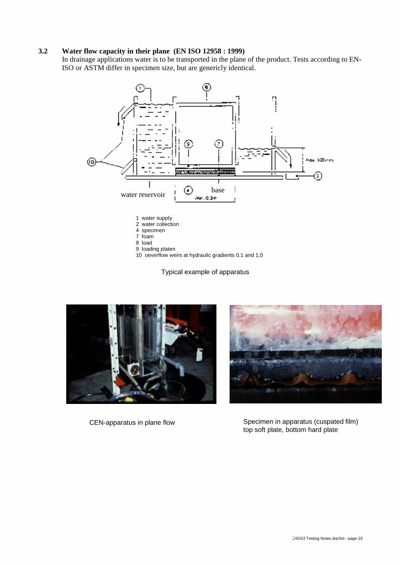
3.2 Water flow capacity in their plane (EN ISO 12958 : 1999)In drainage applications water is to be transported in the plane of the product. Tests according to EN-ISO or ASTM differ in specimen size, but are genericly identical.
1 water supply2 water collection4 specimen7 foam8 load9 loading platen10 oeverflow weirs at hydraulic gradients 0,1 and 1,0
water reservoirbase
Typical example of apparatus
CEN-apparatus in plane flow Specimen in apparatus (cuspated film)top soft plate, bottom hard plate
</IGS3 Testing Notes.doc/bö - page 24
Flow is measured at constant water head and expressed either as kH (kp), unit m/s, or as flowcapacity, unit l/s per m width of the product at given gradient. The value is dependent of thicknessand thus of time as the materials creep. For a long-term design thickness dependent values have to bemeasured and matched with compressive creep tests.
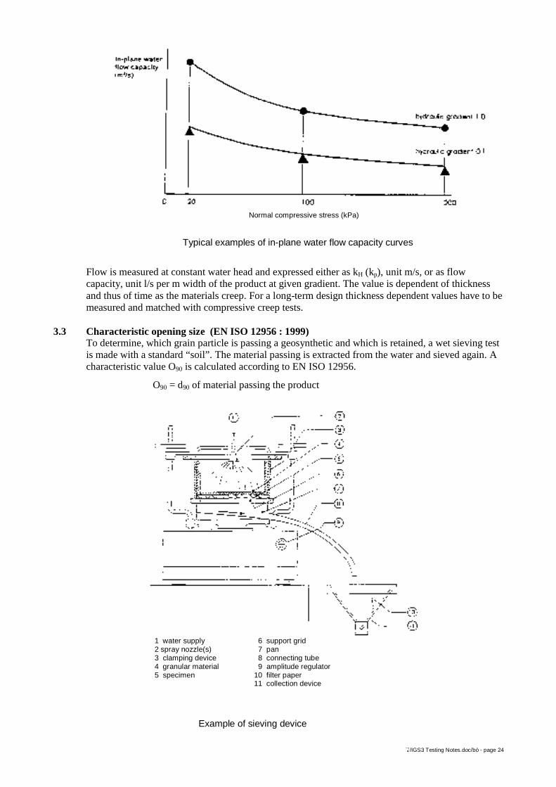
3.3 Characteristic opening size (EN ISO 12956 : 1999)To determine, which grain particle is passing a geosynthetic and which is retained, a wet sieving testis made with a standard “soil”. The material passing is extracted from the water and sieved again. Acharacteristic value O90 is calculated according to EN ISO 12956.
O90 = d90 of material passing the product
Example of sieving device
Typical examples of in-plane water flow capacity curves
Normal compressive stress (kPa)
1 water supply 6 support grid2 spray nozzle(s) 7 pan3 clamping device 8 connecting tube4 granular material 9 amplitude regulator5 specimen 10 filter paper
11 collection device
</IGS3 Testing Notes.doc/bö - page 25
Tests according to other standards take single grade sand or glass-spheres to measure similarproperties.
4 Durability propertiesGeosynthetics may serve for temporary structures as access roads for construction sites or may beneeded temporarily until consolidation of soils. Long-term application is the majority of applications(30 or 60 years are values numbered in UK; more than 120 years are required for landfills inGermany). Therefore durability is an important requirement.
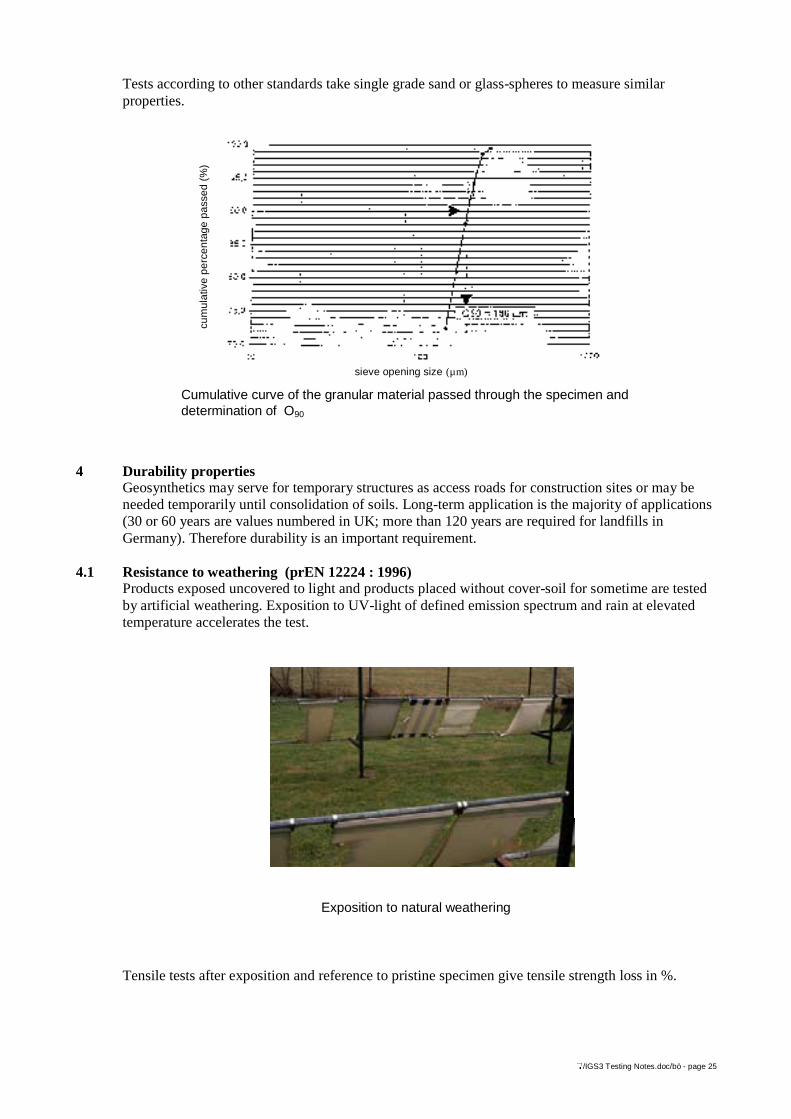
4.1 Resistance to weathering (prEN 12224 : 1996)Products exposed uncovered to light and products placed without cover-soil for sometime are testedby artificial weathering. Exposition to UV-light of defined emission spectrum and rain at elevatedtemperature accelerates the test.
Tensile tests after exposition and reference to pristine specimen give tensile strength loss in %.
Cumulative curve of the granular material passed through the specimen anddetermination of O90
cum
ulat
ive
perc
enta
ge p
asse
d (%
)
sieve opening size (µm)
Exposition to natural weathering
</IGS3 Testing Notes.doc/bö - page 26
4.2 Resistance to microbiological degradation (ENV 12225 : 1996)Fungi and bacteria living in soils may attack the polymeric materials used as geosynthetics. (There isno failure reported till now by this). To check the resistance the product to be tested is buried inbiologically active soil and after the “soil burial” test residual strength is measured. ENV 12224gives types of bacteria and environments.
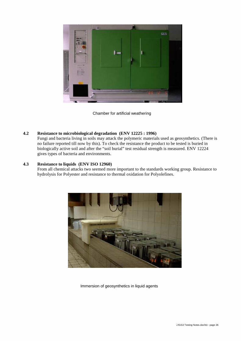
4.3 Resistance to liquids (ENV ISO 12960)From all chemical attacks two seemed more important to the standards working group. Resistance tohydrolysis for Polyester and resistance to thermal oxidation for Polyolefines.
Chamber for artificial weathering
Immersion of geosynthetics in liquid agents
</IGS3 Testing Notes.doc/bö - page 27
4.3.1 Resistance to hydrolysis (prEN 12447)Hydrolysis of Polyester is the reverse action of the evolution by polycondensation and meansconnecting water molecules or parts to the PET molecules, thus increasing the Carboxyl end group(CEG)-content and decreasing the average molecular weight often expressed as solution viscosity.External hydrolysis by alcaline attak occurs also at low temperatures, internal hydrolysis in neutralenvironments is relevant at elevated temperatures.Products are immersed in liquids for times up to 90 days and residual strength and deformation aretested.
4.3.2 Resistance to thermal oxidation (prEN ISO 13430)To the polyolefine molecules of PE, PP oxygen may be connected creating increased brittleness ofthe polymers. Stabilizing additives delay this oxidation. For the test the products are exposed to hightemperature in an oven.