Embed Size (px)
Citation preview
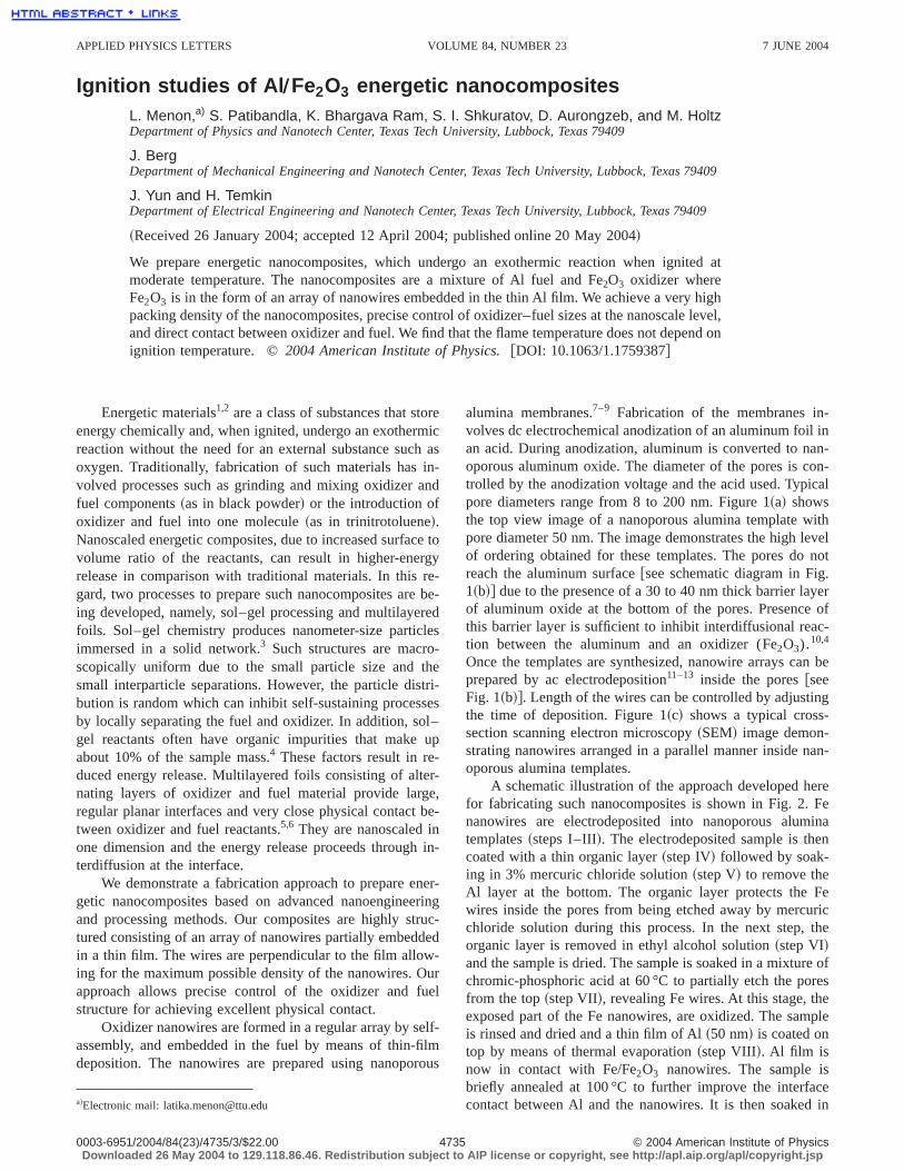
Ignition studies of Al ÕFe2O3 energetic nanocompositesL. Menon,a) S. Patibandla, K. Bhargava Ram, S. I. Shkuratov, D. Aurongzeb, and M. HoltzDepartment of Physics and Nanotech Center, Texas Tech University, Lubbock, Texas 79409
J. BergDepartment of Mechanical Engineering and Nanotech Center, Texas Tech University, Lubbock, Texas 79409
J. Yun and H. TemkinDepartment of Electrical Engineering and Nanotech Center, Texas Tech University, Lubbock, Texas 79409
~Received 26 January 2004; accepted 12 April 2004; published online 20 May 2004!
We prepare energetic nanocomposites, which undergo an exothermic reaction when ignited atmoderate temperature. The nanocomposites are a mixture of Al fuel and Fe2O3 oxidizer whereFe2O3 is in the form of an array of nanowires embedded in the thin Al film. We achieve a very highpacking density of the nanocomposites, precise control of oxidizer–fuel sizes at the nanoscale level,and direct contact between oxidizer and fuel. We find that the flame temperature does not depend onignition temperature. ©2004 American Institute of Physics.@DOI: 10.1063/1.1759387#
Energetic materials1,2 are a class of substances that storeenergy chemically and, when ignited, undergo an exothermicreaction without the need for an external substance such asoxygen. Traditionally, fabrication of such materials has in-volved processes such as grinding and mixing oxidizer andfuel components~as in black powder! or the introduction ofoxidizer and fuel into one molecule~as in trinitrotoluene!.Nanoscaled energetic composites, due to increased surface tovolume ratio of the reactants, can result in higher-energyrelease in comparison with traditional materials. In this re-gard, two processes to prepare such nanocomposites are be-ing developed, namely, sol–gel processing and multilayeredfoils. Sol–gel chemistry produces nanometer-size particlesimmersed in a solid network.3 Such structures are macro-scopically uniform due to the small particle size and thesmall interparticle separations. However, the particle distri-bution is random which can inhibit self-sustaining processesby locally separating the fuel and oxidizer. In addition, sol–gel reactants often have organic impurities that make upabout 10% of the sample mass.4 These factors result in re-duced energy release. Multilayered foils consisting of alter-nating layers of oxidizer and fuel material provide large,regular planar interfaces and very close physical contact be-tween oxidizer and fuel reactants.5,6 They are nanoscaled inone dimension and the energy release proceeds through in-terdiffusion at the interface.
We demonstrate a fabrication approach to prepare ener-getic nanocomposites based on advanced nanoengineeringand processing methods. Our composites are highly struc-tured consisting of an array of nanowires partially embeddedin a thin film. The wires are perpendicular to the film allow-ing for the maximum possible density of the nanowires. Ourapproach allows precise control of the oxidizer and fuelstructure for achieving excellent physical contact.
Oxidizer nanowires are formed in a regular array by self-assembly, and embedded in the fuel by means of thin-filmdeposition. The nanowires are prepared using nanoporous
alumina membranes.7–9 Fabrication of the membranes in-volves dc electrochemical anodization of an aluminum foil inan acid. During anodization, aluminum is converted to nan-oporous aluminum oxide. The diameter of the pores is con-trolled by the anodization voltage and the acid used. Typicalpore diameters range from 8 to 200 nm. Figure 1~a! showsthe top view image of a nanoporous alumina template withpore diameter 50 nm. The image demonstrates the high levelof ordering obtained for these templates. The pores do notreach the aluminum surface@see schematic diagram in Fig.1~b!# due to the presence of a 30 to 40 nm thick barrier layerof aluminum oxide at the bottom of the pores. Presence ofthis barrier layer is sufficient to inhibit interdiffusional reac-tion between the aluminum and an oxidizer (Fe2O3).10,4
Once the templates are synthesized, nanowire arrays can beprepared by ac electrodeposition11–13 inside the pores@seeFig. 1~b!#. Length of the wires can be controlled by adjustingthe time of deposition. Figure 1~c! shows a typical cross-section scanning electron microscopy~SEM! image demon-strating nanowires arranged in a parallel manner inside nan-oporous alumina templates.
A schematic illustration of the approach developed herefor fabricating such nanocomposites is shown in Fig. 2. Fenanowires are electrodeposited into nanoporous aluminatemplates~steps I–III!. The electrodeposited sample is thencoated with a thin organic layer~step IV! followed by soak-ing in 3% mercuric chloride solution~step V! to remove theAl layer at the bottom. The organic layer protects the Fewires inside the pores from being etched away by mercuricchloride solution during this process. In the next step, theorganic layer is removed in ethyl alcohol solution~step VI!and the sample is dried. The sample is soaked in a mixture ofchromic-phosphoric acid at 60 °C to partially etch the poresfrom the top~step VII!, revealing Fe wires. At this stage, theexposed part of the Fe nanowires, are oxidized. The sampleis rinsed and dried and a thin film of Al~50 nm! is coated ontop by means of thermal evaporation~step VIII!. Al film isnow in contact with Fe/Fe2O3 nanowires. The sample isbriefly annealed at 100 °C to further improve the interfacecontact between Al and the nanowires. It is then soaked ina!Electronic mail: [email protected]
APPLIED PHYSICS LETTERS VOLUME 84, NUMBER 23 7 JUNE 2004
47350003-6951/2004/84(23)/4735/3/$22.00 © 2004 American Institute of PhysicsDownloaded 26 May 2004 to 129.118.86.46. Redistribution subject to AIP license or copyright, see http://apl.aip.org/apl/copyright.jsp
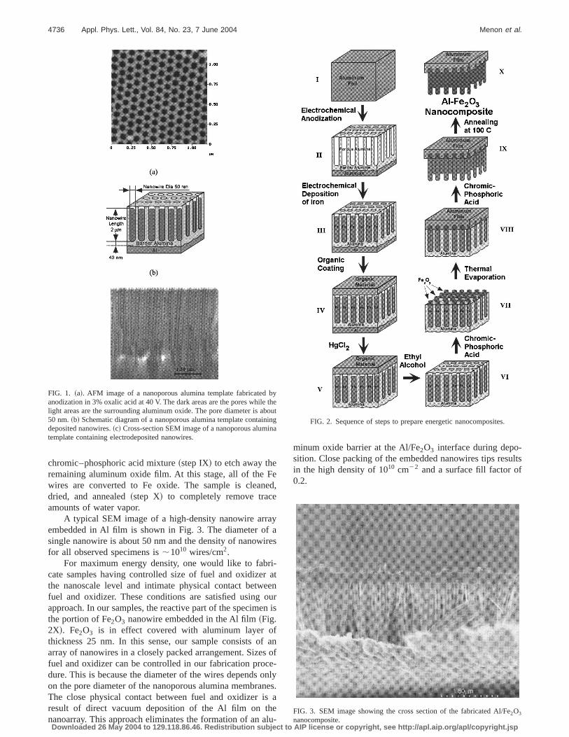
chromic–phosphoric acid mixture~step IX! to etch away theremaining aluminum oxide film. At this stage, all of the Fewires are converted to Fe oxide. The sample is cleaned,dried, and annealed~step X! to completely remove traceamounts of water vapor.
A typical SEM image of a high-density nanowire arrayembedded in Al film is shown in Fig. 3. The diameter of asingle nanowire is about 50 nm and the density of nanowiresfor all observed specimens is;1010 wires/cm2.
For maximum energy density, one would like to fabri-cate samples having controlled size of fuel and oxidizer atthe nanoscale level and intimate physical contact betweenfuel and oxidizer. These conditions are satisfied using ourapproach. In our samples, the reactive part of the specimen isthe portion of Fe2O3 nanowire embedded in the Al film~Fig.2X!. Fe2O3 is in effect covered with aluminum layer ofthickness 25 nm. In this sense, our sample consists of anarray of nanowires in a closely packed arrangement. Sizes offuel and oxidizer can be controlled in our fabrication proce-dure. This is because the diameter of the wires depends onlyon the pore diameter of the nanoporous alumina membranes.The close physical contact between fuel and oxidizer is aresult of direct vacuum deposition of the Al film on thenanoarray. This approach eliminates the formation of an alu-
minum oxide barrier at the Al/Fe2O3 interface during depo-sition. Close packing of the embedded nanowires tips resultsin the high density of 1010 cm22 and a surface fill factor of0.2.
FIG. 1. ~a!. AFM image of a nanoporous alumina template fabricated byanodization in 3% oxalic acid at 40 V. The dark areas are the pores while thelight areas are the surrounding aluminum oxide. The pore diameter is about50 nm.~b! Schematic diagram of a nanoporous alumina template containingdeposited nanowires.~c! Cross-section SEM image of a nanoporous aluminatemplate containing electrodeposited nanowires.
FIG. 2. Sequence of steps to prepare energetic nanocomposites.
FIG. 3. SEM image showing the cross section of the fabricated Al/Fe2O3
nanocomposite.
4736 Appl. Phys. Lett., Vol. 84, No. 23, 7 June 2004 Menon et al.
Downloaded 26 May 2004 to 129.118.86.46. Redistribution subject to AIP license or copyright, see http://apl.aip.org/apl/copyright.jsp

Ignition has been achieved using a butane flame, resis-tive heating element, and laser illumination. Figure 4~b!shows an image of an igniting sample using an electricallyheated filament. Before and after ignition images are alsoshown for comparison in Figs. 4~a! and 4~c!. The tempera-ture of the heating wire is calibrated using an optical pyrom-eter. Ignition temperatures are well below the Al meltingpoint of 660 °C. Ignition is accompanied by a bright flash oflight. The reaction temperature is obtained by measuring theblackbody emission spectrum of the igniting sample. Figure5 shows the plot of flame temperature as a function of igni-tion temperature. Ignition starts at a temperature of;410 °C.As expected, the flame temperature is independent of theignition temperature and is of the order of 4000 °C. The highflame temperature is consistent with the large energy releaseexpected. The flame temperature in our samples may becompared with the reported ‘‘adiabatic flame temperature’’ ofabout 3250 °C for the Al–Fe2O3 reaction.14
The thermite reaction between aluminum and iron oxidecan be written as
Fe2O31Al→Fe1Al2O31DH, ~1!
where DH is the energy released during the reaction. Weestimate the amount of energy released per square centimeterof our samples using the following known values from lit-erature~heat of formation for Al2O3 is 2335 kJ/mole atomand heat of formation for Fe2O3 is 2168 kJ/mole atom!.15
Assuming a volume reaction between Fe2O3 and Al, we es-timate that the energy released is about 0.4 J/cm2. This is athousand times higher than the energy released due to apurely surface reaction~as in planar films!.
In conclusion, we describe a highly reproducible ap-proach to create high-energy density composites. The advan-tage of this technique is precise control of oxidizer and fueldimensions at the nanometer scale. The method precludesboth the incorporation of impurities and the oxidation of thealuminum at the fuel–oxidizer interface prior to ignition. Ig-nition temperatures are well below the melting point of alu-minum, while reaction temperatures are high~;4000 °C!and independent of ignition temperature.
This work was funded in part by the National ScienceFoundation~CTS-0210141 and ECS-0304224! and the J. F.Maddox Foundation.
1W. C. Danen and J. A. Martin, U.S. Patent No. 5,266,132~1993!.2G. P. Dixon, J. A. Martin, and D. Thompson, U.S. Patent No. 5,717,159~1998!.
3A. E. Gash, R. L. Simpson, T. M. Tillotson, J. H. Satcher, and L. W.Hrubesh,Proceedings of the 27th International Pyrotechnics Seminar; pp.41–53, T. M. Tillotson, L. W. Hrubesh, R. S. Lee, R. W. Swansinger, andR. L. Simpson, J. Non-Cryst. Solids225, 358 ~1998!.
4T. M. Tillotson, A. E. Gash, R. L. Simpson, L. W. Hrubesh, J. H. Satcher,and J. F. Poco, J. Non-Cryst. Solids285, 338 ~2001!.
5U. Anselmi-Tamburini and Z. A. Munir, J. Appl. Phys.66, 5039~1989!.6D. Aurongzeb, M. Holtz, M. Daugherty, J. M. Berg, A. Chandolu, J. Yun,and H. Temkin, Appl. Phys. Lett.83, 5437~2003!.
7L. Menon, in Quantum Dots and Nanowires Advances in Nanophase Ma-terials and Nanotechnology, edited by H. S. Nalwa and S. Bandyopadhyay~Amer. Sc. Publ., 2003!.
8H. Masuda and K. Fukuda, Science268, 1466~1995!.9H. Masuda, H. Yamada, M. Satoh, H. Asoh, M. Nakao, and T. Tamamura,Appl. Phys. Lett.71, 2770~1997!.
10This is also known to be problematic in granular mixtures where alumi-num powders rapidly oxidize. The subsequent aluminum oxide coatinginhibits reaction involving the underlying aluminum.
11L. Menon, M. Zheng, H. Zeng, S. Bandyopadhyay, and D. J. Sellmyer, J.Electron. Mater.29, 510 ~2000!.
12S. Bandyopadhyay, L. Menon, N. Kouklin, H. Zeng, and D. J. Sellmyer, J.Electron. Mater.28, 515 ~1999!.
13A. J. Yin, J. Li, A. J. Bennett, and J. M. Xu, Appl. Phys. Lett.79, 1039~2001!.
14Z. A. Munir, Am. Ceram. Soc. Bull.67, 342 ~1988!.15O. B. Kubaschewski, C. B. Alcock, and P. J. Spencer,Materials Thermo-
chemistry, 6th ed.~Pergammon, Oxford, 1993!.
FIG. 4. ~a! Image of energetic sample before ignition~size is of the order ofmillimeters!, ~b! bright flash of light as demonstrate by an igniting sample,and ~c! image of sample after ignition.
FIG. 5. Flame temperature as a function of ignition temperature forAl–Fe2O3 nanocomposites.
4737Appl. Phys. Lett., Vol. 84, No. 23, 7 June 2004 Menon et al.
Downloaded 26 May 2004 to 129.118.86.46. Redistribution subject to AIP license or copyright, see http://apl.aip.org/apl/copyright.jsp