Embed Size (px)
Citation preview
u c! r
Ignition Rate Measurement of Laser-Ignited Coals
Technical Progress Report for period:
July 1, 1995 to September 30, 1995
US Department of Energy
Grant Number: DE-FG22-94MT94012
Submitted by:
and
John C. Chen Assistant Professor
Department of Mechanical Engineering '$ c1
.n; o L _ _ 0 c2-3-*-
e -; 4 ur;l * - 'J r.3 - c 3
-4 fr7p-j
Vinayak Kabadi g 22 -g-= 4 I rnm p- - -1 CY
T r -
p. \--
CS Associate Professor Department of Chemical Engineeringz w. - cj
G) 3 5
October 20,1995
"An Equal Opportunity Employer" A Constituent Institution of Ihc Universi$,of North Carolina
012
Introduction
Over the last several decades many experiments have been conceived to study the
ignition of pulverized coal and other solid fuels. We are constructing a laser-based apparatus
which offers several advantages over those currently in favor. Sieve-sized particles are dropped
batch-wise into a laminar, upward-flow wind tunnel which is constructed with a quartz test
section. The gas stream is not preheated. A single pulse from a Nd:YAG laser is focused
through the tunnel and ignites several particles. The transparent test section and cool walls
allow for application of two-color pyrometry to measure the particles’ temperature history
during ignition and combustion. Coals ranging in rank from lignites to low-volatile
bituminous, and chars derived from these coals, will be studied in this project. For each fuel
type, measurements of the ignition temperature under various experimental conditions
(particle size and free-stream oxygen concentration), combined with a detailed analysis of the
ignition process, will permit the determination of kinetic rate constants of ignition.
This technique offers many advantages over conventional drop-tube furnace
experiments. One is the ability to directly measure ignition temperature rather than inferring
it from measurements of the minimum gas temperature needed to induce ignition. Another
advantage is the high heating rates achievable - on the order of IO6 Ws. This is a significant
improvement over experiments which rely on convective heating from a hot gas, which
typically achieves heating rates of lo4 Us. The higher heating rate more closely simulates
conditions in conventional coal combustors used for power generation.
It should be noted that single-particle behavior governs the conditions of this
experiment; i.e., the particle suspension is dilute enough that particle-to-particle effects (other
than radiative heat transfer) are not important. In actual combustors, particle loading,
especially near the injector, is high enough that such “cooperative effects” dominate. Our
approach is to gain a clear understanding of single-particle behavior with this experiment,
before facing the more difficult problem encountered with cloud suspensions. DISCLAIMER-
This report was prepared as an account of work sponsored by an agency of the United States Government. Neither the United States Government nor any agency thereof, nor any of their employees, makes any warranty, express or implied, or assumes any legal liability or responsi- bility for the accuracy, completeness, or usefulness of any information, apparatus, product, or process disclosed, or represents that its use would not infringe privately owned rights. Refer- ence herein to any specific commercial product, process, or service by trade name, trademark, manufacturer, or otherwise does not necessarily constitute or imply its endorsement, recom- mendation, or favoring by the United States Government or any agency thereof. The views and opinions of authors expressed herein do not necessarily state or reflect those of the United States Government or any agency thereof.
- ~ ~ ~~ . ~~ ~~ ~~ -. ~ ~ ~~~~
- - ~ ~- . --------
Objectives
Our objectives for this project are:
1. Construction of the laserjgnition experiment, including:
1.1.
1.2. wind tunnel;
gas delivery and regulation system;
1.3. exhaust system;
1.4.
1.5. optical detection system; and
1.6. data acquisition and processing;
laser system and beam-guiding optics;
2.
3.
4.
Shakedown testing of the various components;
Ignition of coals of various rank, from lignites to low-volatile bituminous;
Measurement of the ignition temperatures of these fuels under various experimental
conditions (particle size and free-stream oxygen concentration);
Extraction of ignition rate constants from temperature measurements by application of an
appropriate heterogeneous-ignition analysis.
5.
Accomplishments in This Quarter
Personnel Two undergraduate students, Cynthia Marshall and Monique Jenkins, have been
recruited to work on this project for the current academic year. Both are seniors with an
interest in the thermal sciences area of mechanical engineering. Ms. Marshall is assisting the
graduate student in the laboratory with experiment set-up and conduct of the experiments,
while Ms. Jenkins is conducting a literature search on high-speed photography using a
conventional 35-mm camera. The latter task is in preparation for the near future, when we
will attempt to acquire photographs of igniting particles from this experiment.
Experimenf During this reporting period, the coal samples have all been prepared by dry sieving into
the following size fractions: 53-63 pm, 64-75 pm, 76-90 pm, 91-106 pm, 107-125 pm, 126-150
pm, 151-180 pm. The coals to be used, and their ASTM rank, are:
2
Penn State designation, DECS-13 DECS-19 DECS-23 DECS-24 DECS-25 DECS-26
Seam name Sewell
Pocahontas #3 Pittsburgh Illinois #6
rust Wyodak
ASTM rank medium-volatile bituminous
low-volatile bituminous high-volatile A bituminous high-volatile C bituminous
lignite A subbituminous B
The experiment set-up is nearly complete, with the construction of the laser gate (used
to deliver a single laser pulse to the experiment) and its controller remaining. We constructed
and tested the pulsed coal feeder, set up the laser beam-steering optics, and designed and built a
low-cost, rugged, photodiode detector for ignition determination. We are reserving the
photomultiplier tube detector system for future use, when we begin to make temperature
measurements.
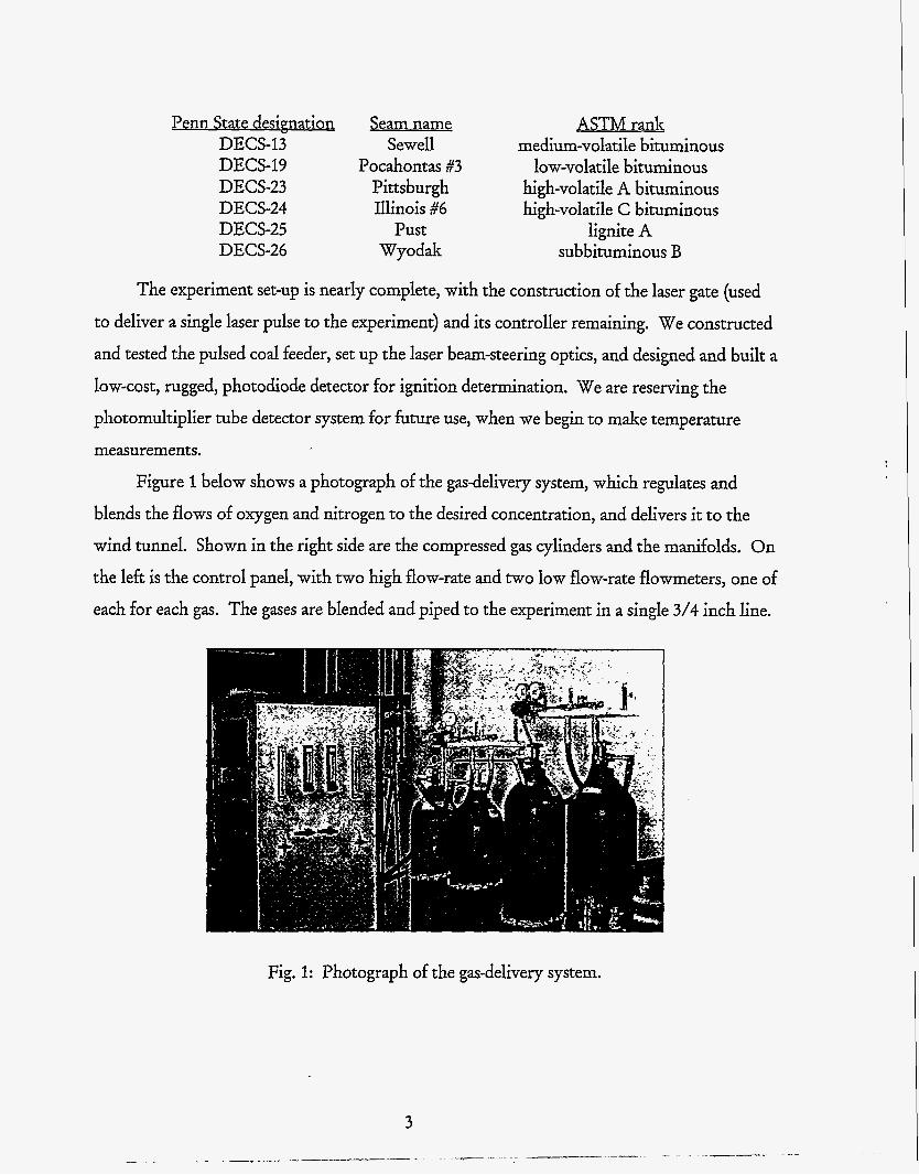
Figure 1 below shows a photograph of the gas-delivery system, which regulates and
blends the flows of oxygen and nitrogen to the desired concentration, and delivers it to the
wind tunnel. Shown in the right side are the compressed gas cylinders and the manifolds. On
the left is the control panel, with two high flow-rate and two low flow-rate flowmeters, one of
each for each gas. The gases are blended and piped to the experiment in a single 3/4 inch line.
Fig. 1: Photograph of the gas-delivery system.
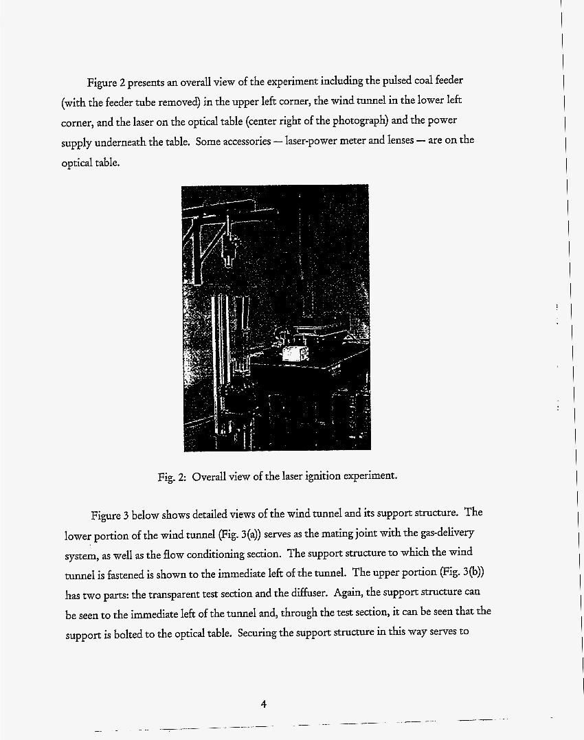
Figure 2 presents an overall view of the experiment including the pulsed coal feeder
(with the feeder tube removed) in the upper left corner, the wind tunnel in the lower left corner, and the laser on the optical table (center right of the photograph) and the power
supply underneath the table. Some accessories - laser-power meter and lenses - are on the optical table.
Figure 3 below shows detailed views of the wind tunnel and its support structure. The
lower portion of the wind tunnel (Fig. 3(a)) serves as the mating joint with the gas-delivery
system, as well as the flow conditioning section. The support structure to which the wind
tunnel is fastened is shown to the immediate left of the tunnel. The upper portion (Fig. 3(b))
has two parts: the transparent test section and the diffuser. Again, the support structure can
be seen to the immediate left of the tunnel and, through the test section, it can be seen that the
support is bolted to the optical table. Securing the support structure in this way serves to
4
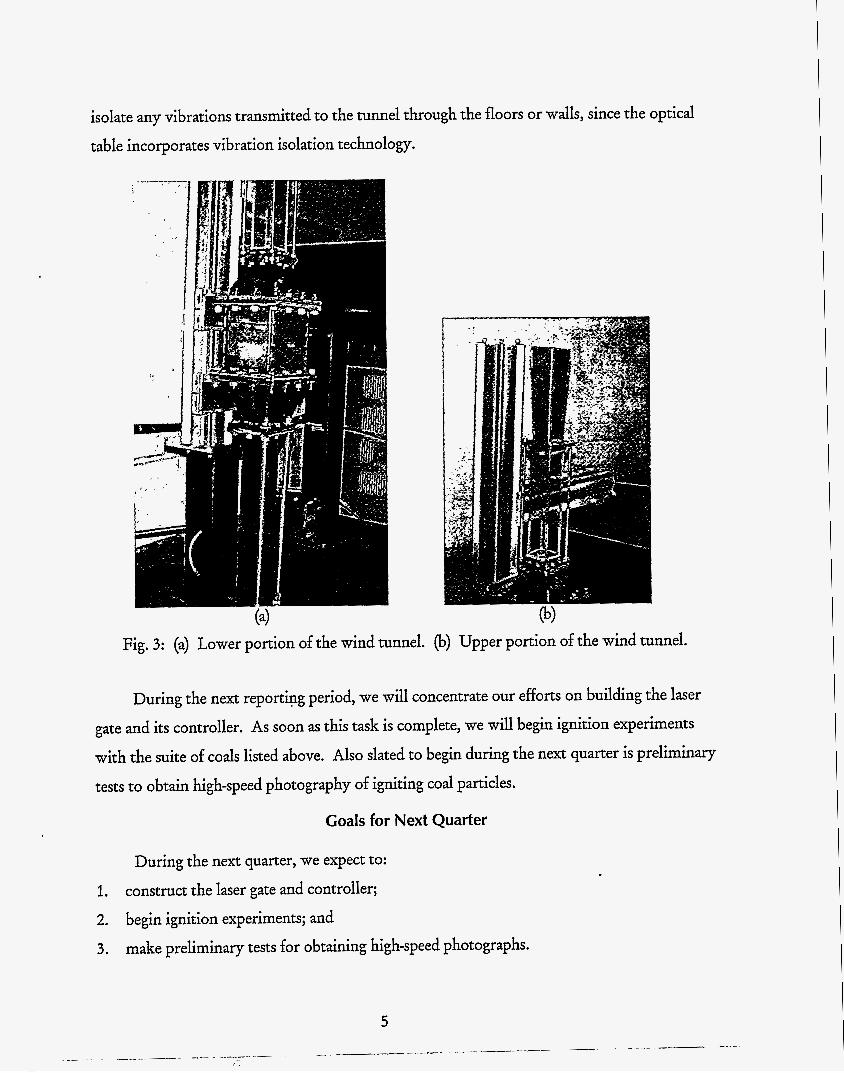
isolate any vibrations transmitted to the tunnel through the floors or walls, since the optical
table incorporates vibration isolation technology.
(4 . .
Fig. 3: (a) Lower portion of the wind tunnel. (b) Upper portion of the wind tunnel.
During the next reportipg period, we will concentrate our efforts on building the laser
gate and its controller. As soon as this task is complete, we will begin ignition experiments
with the suite of coals listed above. Also slated to begin during the next quarter is preliminary
tests to obtain high-speed photography of igniting coal particles.
Goals for Next Quarter
During the next quarter, we expect to:
1.
2. begin ignition experiments; and
3.
construct the laser gate and controller;
make preliminary tests for obtaining high-speed photographs.
5