Embed Size (px)
Citation preview
IG00U-07
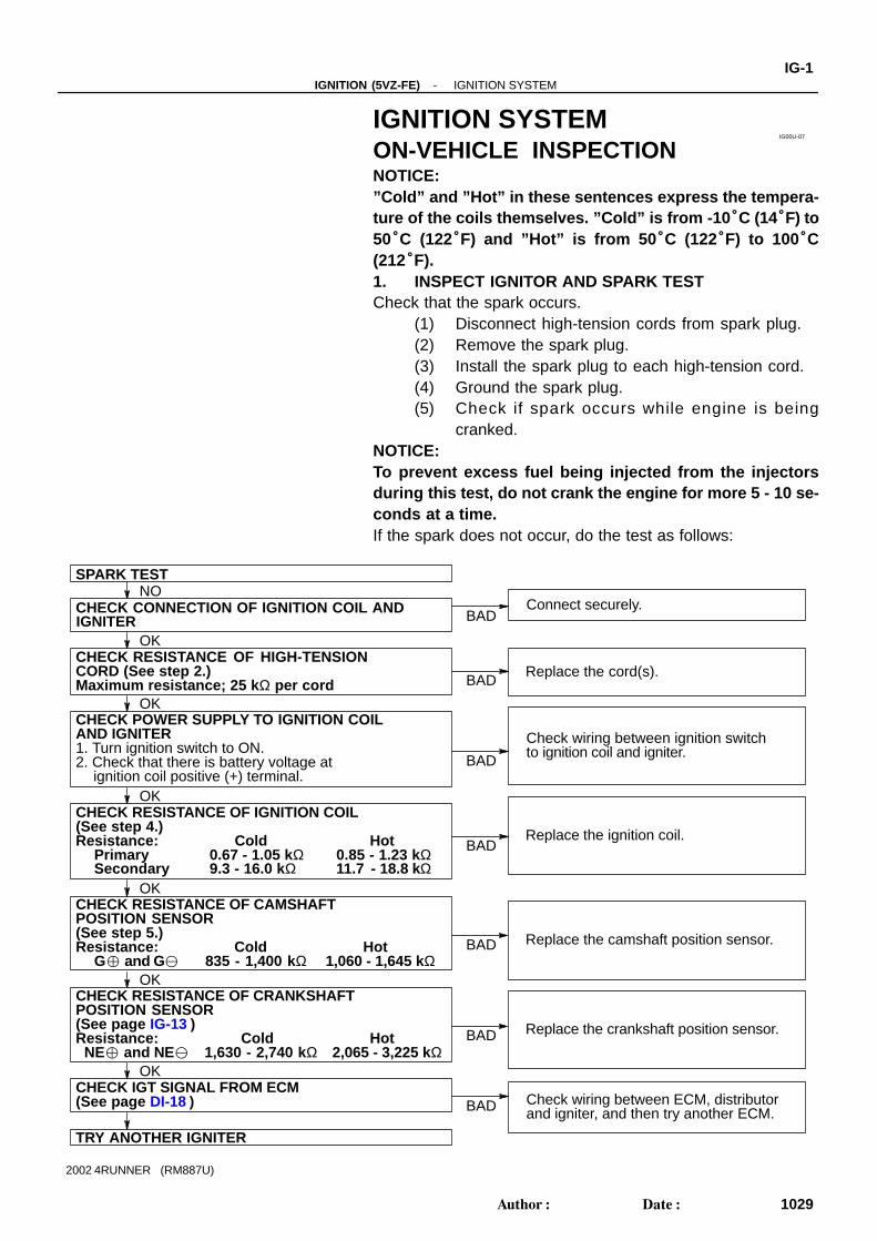
SPARK TEST
CHECK CONNECTION OF IGNITION COIL AND
CHECK RESISTANCE OF HIGH-TENSION
TRY ANOTHER IGNITER
Maximum resistance; 25 k Ω per cordCORD (See step 2.)
CHECK POWER SUPPLY TO IGNITION COILAND IGNITER1. Turn ignition switch to ON.2. Check that there is battery voltage at
ignition coil positive (+) terminal.
Check wiring between ECM, distributor
CHECK RESISTANCE OF IGNITION COIL(See step 4.)Resistance: Cold
PrimaryHot
0.67 - 1.05 kΩ 0.85 - 1.23 kΩ
POSITION SENSOR(See step 5.)Resistance: Cold
G and GHot
835 - 1,400 kΩ 1,060 - 1,645 kΩ
CHECK RESISTANCE OF CAMSHAFT
POSITION SENSOR
Resistance: ColdNE and NE
Hot1,630 - 2,740 kΩ 2,065 - 3,225 kΩ
CHECK RESISTANCE OF CRANKSHAFT
CHECK IGT SIGNAL FROM ECMOK
NO
BAD
OK
OK
OK
OK
OK
Connect securely.
Replace the cord(s).
Check wiring between ignition switchto ignition coil and igniter.
Replace the ignition coil.
Replace the camshaft position sensor.
Replace the crankshaft position sensor.
and igniter, and then try another ECM.
BAD
BAD
BAD
BAD
BAD
BAD
IGNITER
Secondary 9.3 - 16.0 k Ω 11.7 - 18.8 kΩ
(See page IG-13 )
(See page DI-18 )
-IGNITION (5VZ-FE) IGNITION SYSTEMIG-1
1029Author: Date:
2002 4RUNNER (RM887U)
IGNITION SYSTEMON-VEHICLE INSPECTIONNOTICE:”Cold” and ”Hot” in these sentences express the tempera-ture of the coils themselves. ”Cold” is from -10 °C (14°F) to50°C (122°F) and ”Hot” is from 50 °C (122°F) to 100°C(212°F).1. INSPECT IGNITOR AND SPARK TESTCheck that the spark occurs.
(1) Disconnect high-tension cords from spark plug.(2) Remove the spark plug.(3) Install the spark plug to each high-tension cord.(4) Ground the spark plug.(5) Check if spark occurs while engine is being
cranked.NOTICE:To prevent excess fuel being injected from the injectorsduring this test, do not crank the engine for more 5 - 10 se-conds at a time.If the spark does not occur, do the test as follows:
S02423
WRONG
CORRECT
P20435
P20439
Ohmmeter
IG-2-IGNITION (5VZ-FE) IGNITION SYSTEM
1030Author: Date:
2002 4RUNNER (RM887U)
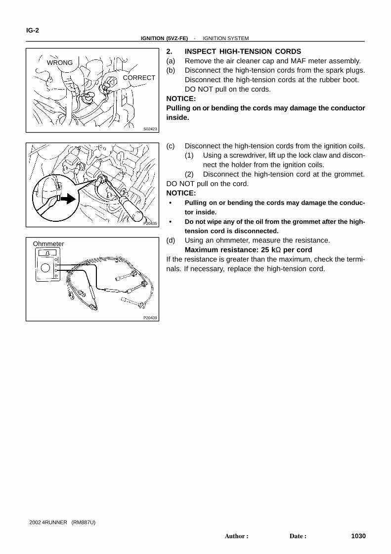
2. INSPECT HIGH-TENSION CORDS(a) Remove the air cleaner cap and MAF meter assembly.(b) Disconnect the high-tension cords from the spark plugs.
Disconnect the high-tension cords at the rubber boot.DO NOT pull on the cords.
NOTICE:Pulling on or bending the cords may damage the conductorinside.
(c) Disconnect the high-tension cords from the ignition coils.(1) Using a screwdriver, lift up the lock claw and discon-
nect the holder from the ignition coils.(2) Disconnect the high-tension cord at the grommet.
DO NOT pull on the cord.NOTICE: Pulling on or bending the cords may damage the conduc-
tor inside. Do not wipe any of the oil from the grommet after the high-
tension cord is disconnected.(d) Using an ohmmeter, measure the resistance.
Maximum resistance: 25 k Ω per cordIf the resistance is greater than the maximum, check the termi-nals. If necessary, replace the high-tension cord.
S02125
P20580
Push
P04690
CORRECT
WRONG
-IGNITION (5VZ-FE) IGNITION SYSTEMIG-3
1031Author: Date:
2002 4RUNNER (RM887U)
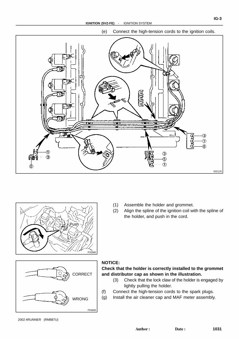
(e) Connect the high-tension cords to the ignition coils.
(1) Assemble the holder and grommet.(2) Align the spline of the ignition coil with the spline of
the holder, and push in the cord.
NOTICE:Check that the holder is correctly installed to the grommetand distributor cap as shown in the illustration.
(3) Check that the lock claw of the holder is engaged bylightly pulling the holder.
(f) Connect the high-tension cords to the spark plugs.(g) Install the air cleaner cap and MAF meter assembly.
P20430
16 mm Plug Wrench
IG0152
P20433
P20584
IG-4-IGNITION (5VZ-FE) IGNITION SYSTEM
1032Author: Date:
2002 4RUNNER (RM887U)
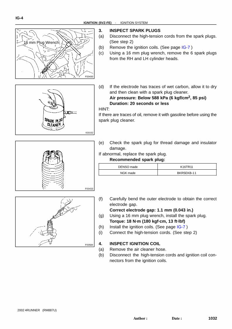
3. INSPECT SPARK PLUGS(a) Disconnect the high-tension cords from the spark plugs.
(See step 2)(b) Remove the ignition coils. (See page IG-7 )(c) Using a 16 mm plug wrench, remove the 6 spark plugs
from the RH and LH cylinder heads.
(d) If the electrode has traces of wet carbon, allow it to dryand then clean with a spark plug cleaner.Air pressure: Below 588 kPa (6 kgf/cm 2, 85 psi)Duration: 20 seconds or less
HINT:If there are traces of oil, remove it with gasoline before using thespark plug cleaner.
(e) Check the spark plug for thread damage and insulatordamage.
If abnormal, replace the spark plug.Recommended spark plug:
DENSO made K16TR11
NGK made BKR5EKB-11
(f) Carefully bend the outer electrode to obtain the correctelectrode gap.Correct electrode gap: 1.1 mm (0.043 in.)
(g) Using a 16 mm plug wrench, install the spark plug.Torque: 18 N·m (180 kgf·cm, 13 ft·lbf)
(h) Install the ignition coils. (See page IG-7 )(i) Connect the high-tension cords. (See step 2)
4. INSPECT IGNITION COIL(a) Remove the air cleaner hose.(b) Disconnect the high-tension cords and ignition coil con-
nectors from the ignition coils.
P20579
Ohmmeter
P21135
Ohmmeter
P20436
Ohmmeter
-IGNITION (5VZ-FE) IGNITION SYSTEMIG-5
1033Author: Date:
2002 4RUNNER (RM887U)
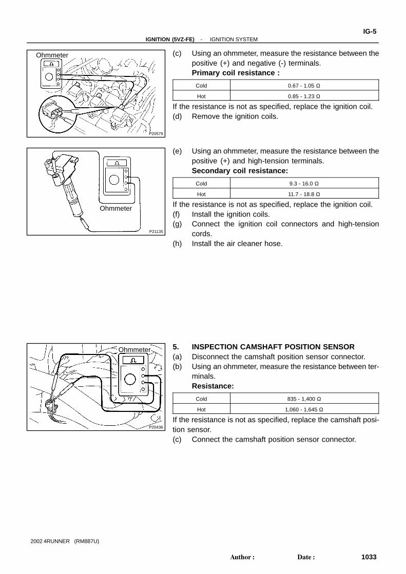
(c) Using an ohmmeter, measure the resistance between thepositive (+) and negative (-) terminals.Primary coil resistance :
Cold 0.67 - 1.05 Ω
Hot 0.85 - 1.23 Ω
If the resistance is not as specified, replace the ignition coil.(d) Remove the ignition coils.
(e) Using an ohmmeter, measure the resistance between thepositive (+) and high-tension terminals.Secondary coil resistance:
Cold 9.3 - 16.0 Ω
Hot 11.7 - 18.8 Ω
If the resistance is not as specified, replace the ignition coil.(f) Install the ignition coils.(g) Connect the ignition coil connectors and high-tension
cords.(h) Install the air cleaner hose.
5. INSPECTION CAMSHAFT POSITION SENSOR(a) Disconnect the camshaft position sensor connector.(b) Using an ohmmeter, measure the resistance between ter-
minals.Resistance:
Cold 835 - 1,400 Ω
Hot 1,060 - 1,645 Ω
If the resistance is not as specified, replace the camshaft posi-tion sensor.(c) Connect the camshaft position sensor connector.
IG00V-02
S02126
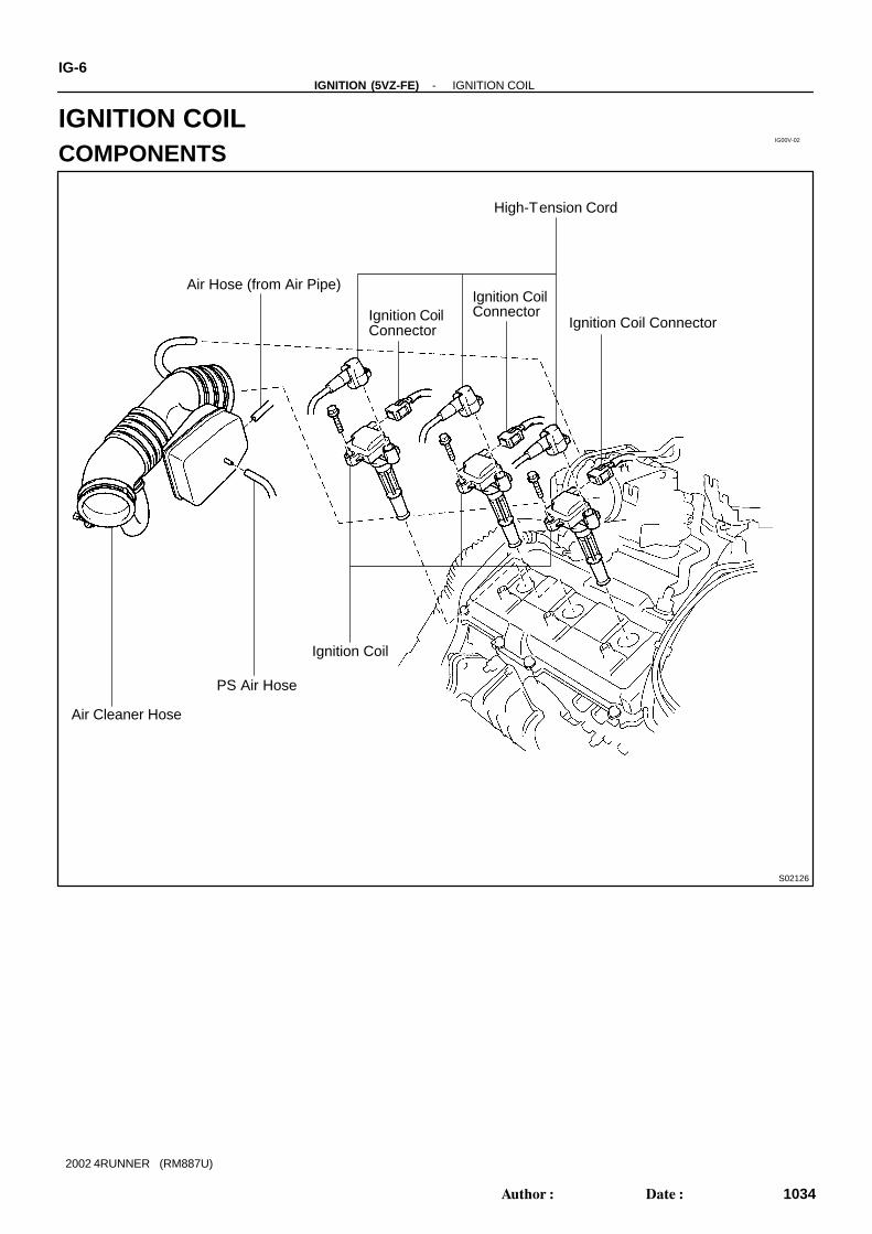
Air Cleaner Hose
PS Air Hose
Ignition Coil
Air Hose (from Air Pipe)
High-Tension Cord
Ignition Coil ConnectorIgnition CoilConnector
Ignition CoilConnector
IG-6-IGNITION (5VZ-FE) IGNITION COIL
1034Author: Date:
2002 4RUNNER (RM887U)
IGNITION COILCOMPONENTS
IG00W-03
S02127
-IGNITION (5VZ-FE) IGNITION COILIG-7
1035Author: Date:
2002 4RUNNER (RM887U)
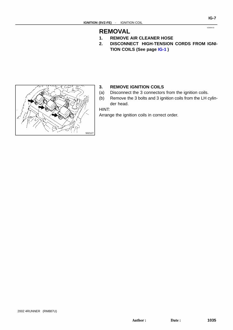
REMOVAL1. REMOVE AIR CLEANER HOSE2. DISCONNECT HIGH-TENSION CORDS FROM IGNI-
TION COILS (See page IG-1 )
3. REMOVE IGNITION COILS(a) Disconnect the 3 connectors from the ignition coils.(b) Remove the 3 bolts and 3 ignition coils from the LH cylin-
der head.HINT:Arrange the ignition coils in correct order.
IG0DI-01
S02127
IG-8-IGNITION (5VZ-FE) IGNITION COIL
1036Author: Date:
2002 4RUNNER (RM887U)
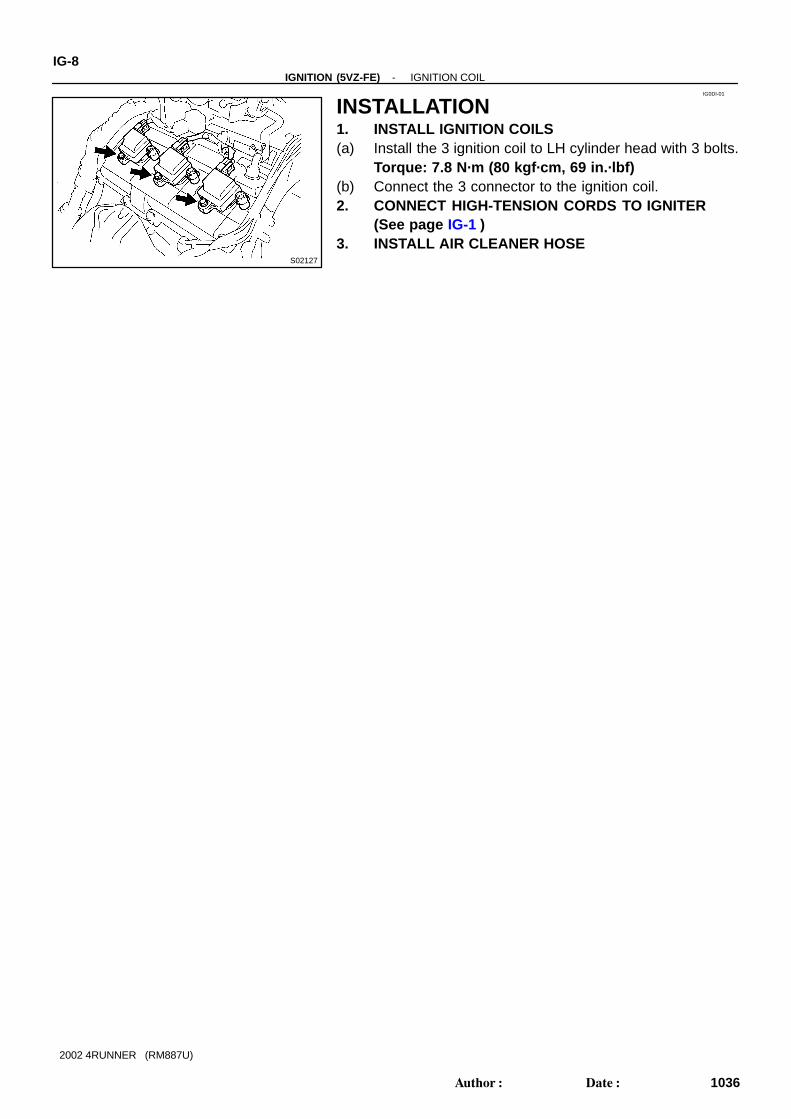
INSTALLATION1. INSTALL IGNITION COILS(a) Install the 3 ignition coil to LH cylinder head with 3 bolts.
Torque: 7.8 N·m (80 kgf·cm, 69 in.·lbf)(b) Connect the 3 connector to the ignition coil.2. CONNECT HIGH-TENSION CORDS TO IGNITER
(See page IG-1 )3. INSTALL AIR CLEANER HOSE
IG00Y-03
S02422
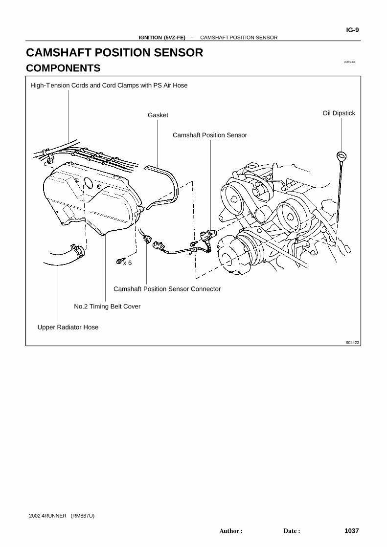
Oil Dipstick
High-Tension Cords and Cord Clamps with PS Air Hose
Gasket
Camshaft Position Sensor
Upper Radiator Hose
No.2 Timing Belt Cover
Camshaft Position Sensor Connector
x 6
-IGNITION (5VZ-FE) CAMSHAFT POSITION SENSORIG-9
1037Author: Date:
2002 4RUNNER (RM887U)
CAMSHAFT POSITION SENSORCOMPONENTS
IG00Z-03
P20432
IG-10-IGNITION (5VZ-FE) CAMSHAFT POSITION SENSOR
1038Author: Date:
2002 4RUNNER (RM887U)
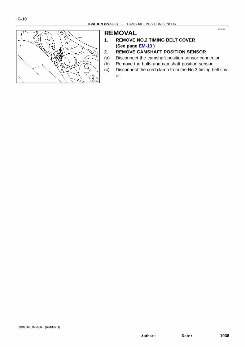
REMOVAL1. REMOVE NO.2 TIMING BELT COVER
(See page EM-13 )2. REMOVE CAMSHAFT POSITION SENSOR(a) Disconnect the camshaft position sensor connector.(b) Remove the bolts and camshaft position sensor.(c) Disconnect the cord clamp from the No.3 timing belt cov-
er.
IG0DJ-01
P20432
-IGNITION (5VZ-FE) CAMSHAFT POSITION SENSORIG-1 1
1039Author: Date:
2002 4RUNNER (RM887U)
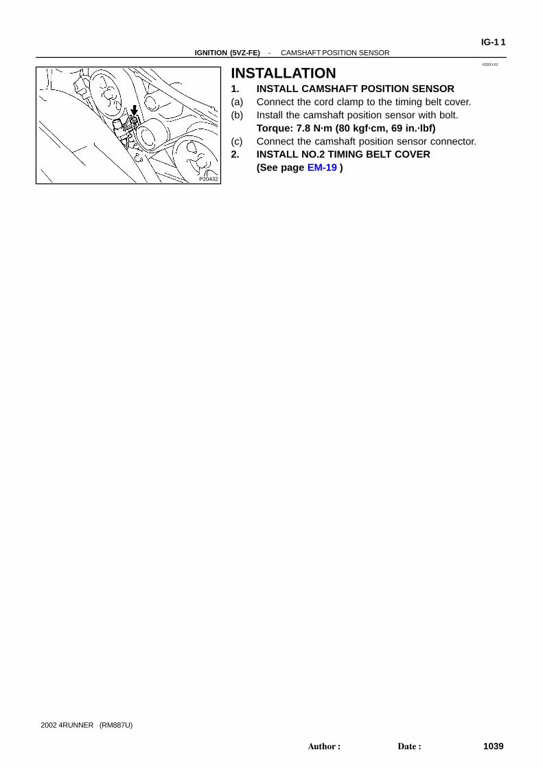
INSTALLATION1. INSTALL CAMSHAFT POSITION SENSOR(a) Connect the cord clamp to the timing belt cover.(b) Install the camshaft position sensor with bolt.
Torque: 7.8 N·m (80 kgf·cm, 69 in.·lbf)(c) Connect the camshaft position sensor connector.2. INSTALL NO.2 TIMING BELT COVER
(See page EM-19 )
P20434
IG011-03
IG-12-IGNITION (5VZ-FE) CRANKSHAFT POSITION SENSOR
1040Author: Date:
2002 4RUNNER (RM887U)
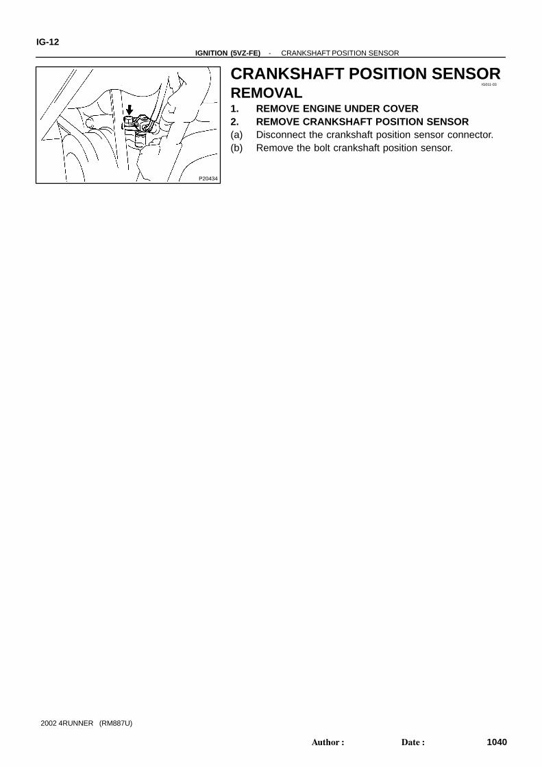
CRANKSHAFT POSITION SENSORREMOVAL1. REMOVE ENGINE UNDER COVER2. REMOVE CRANKSHAFT POSITION SENSOR(a) Disconnect the crankshaft position sensor connector.(b) Remove the bolt crankshaft position sensor.
IG012-03
P20431
Ohmmeter
-IGNITION (5VZ-FE) CRANKSHAFT POSITION SENSORIG-13
1041Author: Date:
2002 4RUNNER (RM887U)
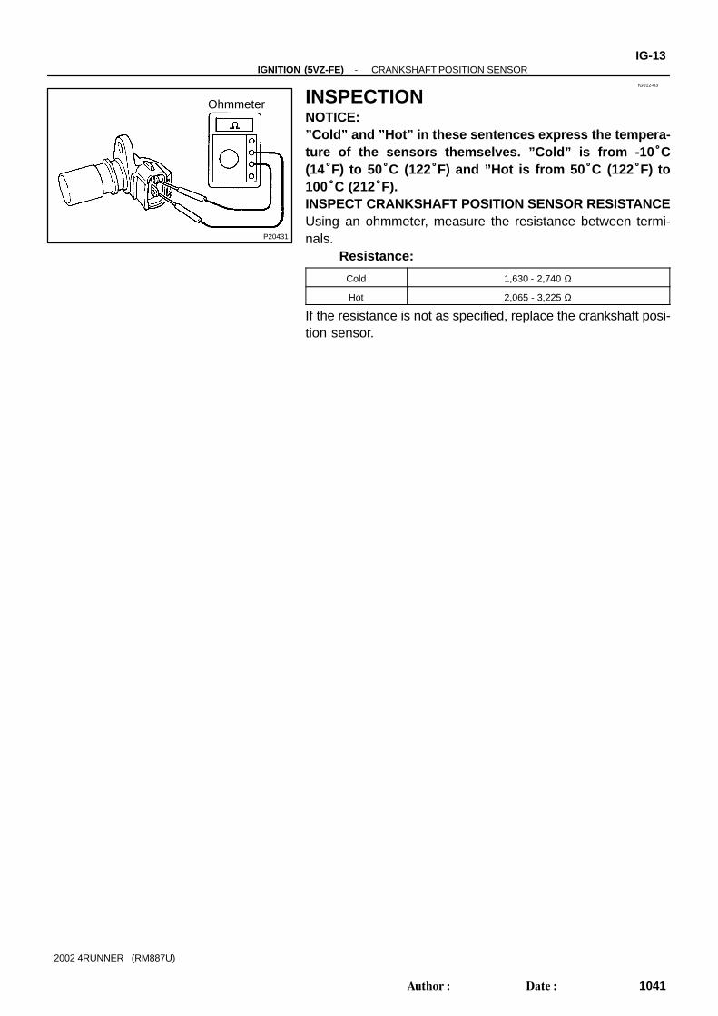
INSPECTIONNOTICE:”Cold” and ”Hot” in these sentences express the tempera-ture of the sensors themselves. ”Cold” is from -10 °C(14°F) to 50°C (122°F) and ”Hot is from 50 °C (122°F) to100°C (212°F).INSPECT CRANKSHAFT POSITION SENSOR RESISTANCEUsing an ohmmeter, measure the resistance between termi-nals.
Resistance:
Cold 1,630 - 2,740 Ω
Hot 2,065 - 3,225 Ω
If the resistance is not as specified, replace the crankshaft posi-tion sensor.
IG0DK-01
P20434
IG-14-IGNITION (5VZ-FE) CRANKSHAFT POSITION SENSOR
1042Author: Date:
2002 4RUNNER (RM887U)
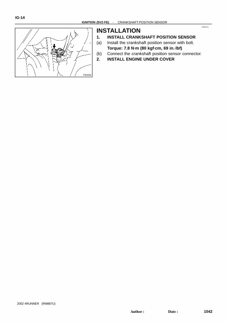
INSTALLATION1. INSTALL CRANKSHAFT POSITION SENSOR(a) Install the crankshaft position sensor with bolt.
Torque: 7.8 N·m (80 kgf·cm, 69 in.·lbf)(b) Connect the crankshaft position sensor connector.2. INSTALL ENGINE UNDER COVER