Embed Size (px)
Citation preview
IGMP Snooping and MVR Configuration Guide, Cisco IOS Release15.2(3)E (Catalyst 2960-X Switch)First Published: December 10, 2014
Americas HeadquartersCisco Systems, Inc.170 West Tasman DriveSan Jose, CA 95134-1706USAhttp://www.cisco.comTel: 408 526-4000 800 553-NETS (6387)Fax: 408 527-0883
THE SPECIFICATIONS AND INFORMATION REGARDING THE PRODUCTS IN THIS MANUAL ARE SUBJECT TO CHANGE WITHOUT NOTICE. ALL STATEMENTS,INFORMATION, AND RECOMMENDATIONS IN THIS MANUAL ARE BELIEVED TO BE ACCURATE BUT ARE PRESENTED WITHOUT WARRANTY OF ANY KIND,EXPRESS OR IMPLIED. USERS MUST TAKE FULL RESPONSIBILITY FOR THEIR APPLICATION OF ANY PRODUCTS.
THE SOFTWARE LICENSE AND LIMITEDWARRANTY FOR THE ACCOMPANYING PRODUCT ARE SET FORTH IN THE INFORMATION PACKET THAT SHIPPED WITHTHE PRODUCT AND ARE INCORPORATED HEREIN BY THIS REFERENCE. IF YOU ARE UNABLE TO LOCATE THE SOFTWARE LICENSE OR LIMITED WARRANTY,CONTACT YOUR CISCO REPRESENTATIVE FOR A COPY.
The Cisco implementation of TCP header compression is an adaptation of a program developed by the University of California, Berkeley (UCB) as part of UCB's public domain versionof the UNIX operating system. All rights reserved. Copyright © 1981, Regents of the University of California.
NOTWITHSTANDINGANYOTHERWARRANTYHEREIN, ALL DOCUMENT FILES AND SOFTWARE OF THESE SUPPLIERS ARE PROVIDED “AS IS"WITH ALL FAULTS.CISCO AND THE ABOVE-NAMED SUPPLIERS DISCLAIM ALL WARRANTIES, EXPRESSED OR IMPLIED, INCLUDING, WITHOUT LIMITATION, THOSE OFMERCHANTABILITY, FITNESS FORA PARTICULAR PURPOSEANDNONINFRINGEMENTORARISING FROMACOURSEOFDEALING, USAGE, OR TRADE PRACTICE.
IN NO EVENT SHALL CISCO OR ITS SUPPLIERS BE LIABLE FOR ANY INDIRECT, SPECIAL, CONSEQUENTIAL, OR INCIDENTAL DAMAGES, INCLUDING, WITHOUTLIMITATION, LOST PROFITS OR LOSS OR DAMAGE TO DATA ARISING OUT OF THE USE OR INABILITY TO USE THIS MANUAL, EVEN IF CISCO OR ITS SUPPLIERSHAVE BEEN ADVISED OF THE POSSIBILITY OF SUCH DAMAGES.
Any Internet Protocol (IP) addresses and phone numbers used in this document are not intended to be actual addresses and phone numbers. Any examples, command display output, networktopology diagrams, and other figures included in the document are shown for illustrative purposes only. Any use of actual IP addresses or phone numbers in illustrative content is unintentionaland coincidental.
Cisco and the Cisco logo are trademarks or registered trademarks of Cisco and/or its affiliates in the U.S. and other countries. To view a list of Cisco trademarks, go to this URL: http://www.cisco.com/go/trademarks. Third-party trademarks mentioned are the property of their respective owners. The use of the word partner does not imply a partnershiprelationship between Cisco and any other company. (1110R)
© 2014 Cisco Systems, Inc. All rights reserved.
C O N T E N T S
P r e f a c e Preface vii
Document Conventions vii
Related Documentation ix
Obtaining Documentation and Submitting a Service Request ix
C H A P T E R 1 Using the Command-Line Interface 1
Information About Using the Command-Line Interface 1
Command Modes 1
Understanding Abbreviated Commands 3
No and Default Forms of Commands 3
CLI Error Messages 4
Configuration Logging 4
Using the Help System 4
How to Use the CLI to Configure Features 6
Configuring the Command History 6
Changing the Command History Buffer Size 6
Recalling Commands 6
Disabling the Command History Feature 7
Enabling and Disabling Editing Features 7
Editing Commands Through Keystrokes 8
Editing Command Lines That Wrap 9
Searching and Filtering Output of show and more Commands 10
Accessing the CLI on a Switch Stack 11
Accessing the CLI Through a Console Connection or Through Telnet 11
C H A P T E R 2 Configuring IGMP Snooping and Multicast VLAN Registration 13
Finding Feature Information 13
IGMP Snooping and MVR Configuration Guide, Cisco IOS Release 15.2(3)E (Catalyst 2960-X Switch) iii
Prerequisites for Configuring IGMP Snooping and MVR 13
Prerequisites for IGMP Snooping 13
Prerequisites for MVR 14
Restrictions for Configuring IGMP Snooping and MVR 14
Restrictions for IGMP Snooping 14
Restrictions for MVR 15
Information About IGMP Snooping and MVR 16
IGMP Snooping 16
IGMP Versions 17
Joining a Multicast Group 17
Leaving a Multicast Group 19
Immediate Leave 20
IGMP Configurable-Leave Timer 20
IGMP Report Suppression 20
IGMP Snooping and Switch Stacks 21
Default IGMP Snooping Configuration 21
Multicast VLAN Registration 22
MVR and IGMP 22
Modes of Operation 22
MVR and Switch Stacks 22
MVR in a Multicast Television Application 23
Default MVR Configuration 24
IGMP Filtering and Throttling 25
Default IGMP Filtering and Throttling Configuration 25
How to Configure IGMP Snooping and MVR 26
Enabling or Disabling IGMP Snooping on a Switch 26
Enabling or Disabling IGMP Snooping on a VLAN Interface 27
Setting the Snooping Method 28
Configuring a Multicast Router Port 30
Configuring a Host Statically to Join a Group 32
Enabling IGMP Immediate Leave 33
Configuring the IGMP Leave Timer 35
Configuring TCN-Related Commands 36
Controlling the Multicast Flooding Time After a TCN Event 36
Recovering from Flood Mode 38
IGMP Snooping and MVR Configuration Guide, Cisco IOS Release 15.2(3)E (Catalyst 2960-X Switch)iv
Contents
Disabling Multicast Flooding During a TCN Event 39
Configuring the IGMP Snooping Querier 41
Disabling IGMP Report Suppression 43
Configuring MVR Global Parameters 44
Configuring MVR Interfaces 47
Configuring IGMP Profiles 49
Applying IGMP Profiles 52
Setting the Maximum Number of IGMP Groups 53
Configuring the IGMP Throttling Action 55
Monitoring IGMP Snooping and MVR 57
Monitoring IGMP Snooping Information 57
Monitoring MVR 58
Monitoring IGMP Filtering and Throttling Configuration 59
Configuration Examples for IGMP Snooping and MVR 59
Example: Configuring IGMP Snooping Using CGMP Packets 59
Example: Enabling a Static Connection to a Multicast Router 59
Example: Configuring a Host Statically to Join a Group 60
Example: Enabling IGMP Immediate Leave 60
Example: Setting the IGMP Snooping Querier Source Address 60
Example: Setting the IGMP Snooping Querier Maximum Response Time 60
Example: Setting the IGMP Snooping Querier Timeout 61
Example: Setting the IGMP Snooping Querier Feature 61
Example: Configuring IGMP Profiles 61
Example: Applying IGMP Profile 61
Example: Setting the Maximum Number of IGMP Groups 61
Example: Configuring MVR Global Parameters 62
Example: Configuring MVR Interfaces 62
Additional References 62
Feature History and Information for IGMP Snooping 63
IGMP Snooping and MVR Configuration Guide, Cisco IOS Release 15.2(3)E (Catalyst 2960-X Switch) v
Contents

IGMP Snooping and MVR Configuration Guide, Cisco IOS Release 15.2(3)E (Catalyst 2960-X Switch)vi
Contents
Preface
This book describes configuration information and examples for IP multicast routing on the switch.
• Document Conventions, page vii
• Related Documentation, page ix
• Obtaining Documentation and Submitting a Service Request, page ix
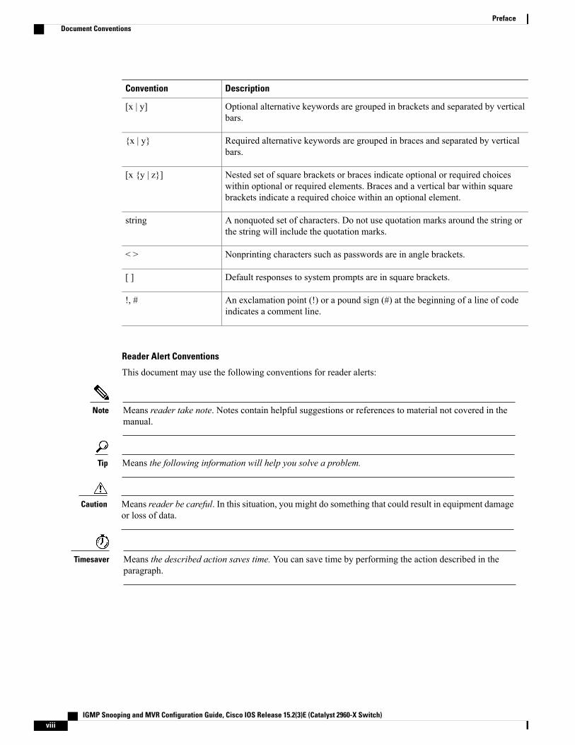
Document ConventionsThis document uses the following conventions:
DescriptionConvention
Both the ^ symbol and Ctrl represent the Control (Ctrl) key on a keyboard. Forexample, the key combination^D orCtrl-Dmeans that you hold down the Controlkey while you press the D key. (Keys are indicated in capital letters but are notcase sensitive.)
^ or Ctrl
Commands and keywords and user-entered text appear in bold font.bold font
Document titles, new or emphasized terms, and arguments for which you supplyvalues are in italic font.
Italic font
Terminal sessions and information the system displays appear in courier font.Courier font
Bold Courier font indicates text that the user must enter.Bold Courier font
Elements in square brackets are optional.[x]
An ellipsis (three consecutive nonbolded periods without spaces) after a syntaxelement indicates that the element can be repeated.
...
A vertical line, called a pipe, indicates a choice within a set of keywords orarguments.
|
IGMP Snooping and MVR Configuration Guide, Cisco IOS Release 15.2(3)E (Catalyst 2960-X Switch) vii
DescriptionConvention
Optional alternative keywords are grouped in brackets and separated by verticalbars.
[x | y]
Required alternative keywords are grouped in braces and separated by verticalbars.
{x | y}
Nested set of square brackets or braces indicate optional or required choiceswithin optional or required elements. Braces and a vertical bar within squarebrackets indicate a required choice within an optional element.
[x {y | z}]
A nonquoted set of characters. Do not use quotation marks around the string orthe string will include the quotation marks.
string
Nonprinting characters such as passwords are in angle brackets.< >
Default responses to system prompts are in square brackets.[ ]
An exclamation point (!) or a pound sign (#) at the beginning of a line of codeindicates a comment line.
!, #
Reader Alert Conventions
This document may use the following conventions for reader alerts:
Means reader take note. Notes contain helpful suggestions or references to material not covered in themanual.
Note
Means the following information will help you solve a problem.Tip
Means reader be careful. In this situation, you might do something that could result in equipment damageor loss of data.
Caution
Means the described action saves time. You can save time by performing the action described in theparagraph.
Timesaver
IGMP Snooping and MVR Configuration Guide, Cisco IOS Release 15.2(3)E (Catalyst 2960-X Switch)viii
PrefaceDocument Conventions
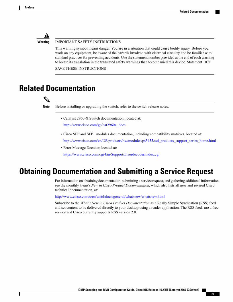
IMPORTANT SAFETY INSTRUCTIONS
This warning symbol means danger. You are in a situation that could cause bodily injury. Before youwork on any equipment, be aware of the hazards involved with electrical circuitry and be familiar withstandard practices for preventing accidents. Use the statement number provided at the end of each warningto locate its translation in the translated safety warnings that accompanied this device. Statement 1071
SAVE THESE INSTRUCTIONS
Warning
Related Documentation
Before installing or upgrading the switch, refer to the switch release notes.Note
• Catalyst 2960-X Switch documentation, located at:
http://www.cisco.com/go/cat2960x_docs
• Cisco SFP and SFP+ modules documentation, including compatibility matrixes, located at:http://www.cisco.com/en/US/products/hw/modules/ps5455/tsd_products_support_series_home.html
• Error Message Decoder, located at:
https://www.cisco.com/cgi-bin/Support/Errordecoder/index.cgi
Obtaining Documentation and Submitting a Service RequestFor information on obtaining documentation, submitting a service request, and gathering additional information,see the monthlyWhat's New in Cisco Product Documentation, which also lists all new and revised Ciscotechnical documentation, at:
http://www.cisco.com/c/en/us/td/docs/general/whatsnew/whatsnew.html
Subscribe to theWhat's New in Cisco Product Documentation as a Really Simple Syndication (RSS) feedand set content to be delivered directly to your desktop using a reader application. The RSS feeds are a freeservice and Cisco currently supports RSS version 2.0.
IGMP Snooping and MVR Configuration Guide, Cisco IOS Release 15.2(3)E (Catalyst 2960-X Switch) ix
PrefaceRelated Documentation

IGMP Snooping and MVR Configuration Guide, Cisco IOS Release 15.2(3)E (Catalyst 2960-X Switch)x
PrefaceObtaining Documentation and Submitting a Service Request
C H A P T E R 1Using the Command-Line Interface
• Information About Using the Command-Line Interface, page 1
• How to Use the CLI to Configure Features, page 6
Information About Using the Command-Line Interface
Command ModesThe Cisco IOS user interface is divided into many different modes. The commands available to you dependon whichmode you are currently in. Enter a questionmark (?) at the system prompt to obtain a list of commandsavailable for each command mode.
You can start a CLI session through a console connection, through Telnet, an SSH, or by using the browser.
When you start a session, you begin in user mode, often called user EXEC mode. Only a limited subset ofthe commands are available in user EXECmode. For example, most of the user EXEC commands are one-timecommands, such as show commands, which show the current configuration status, and clear commands,which clear counters or interfaces. The user EXEC commands are not saved when the switch reboots.
To have access to all commands, youmust enter privileged EXECmode. Normally, youmust enter a passwordto enter privileged EXEC mode. From this mode, you can enter any privileged EXEC command or enterglobal configuration mode.
Using the configurationmodes (global, interface, and line), you canmake changes to the running configuration.If you save the configuration, these commands are stored and used when the switch reboots. To access thevarious configuration modes, you must start at global configuration mode. From global configuration mode,you can enter interface configuration mode and line configuration mode .
This table describes the main command modes, how to access each one, the prompt you see in that mode, andhow to exit the mode.
IGMP Snooping and MVR Configuration Guide, Cisco IOS Release 15.2(3)E (Catalyst 2960-X Switch) 1
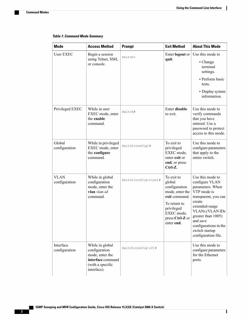
Table 1: Command Mode Summary
About This ModeExit MethodPromptAccess MethodMode
Use this mode to
• Changeterminalsettings.
• Perform basictests.
• Display systeminformation.
Enter logout orquit.Switch>
Begin a sessionusing Telnet, SSH,or console.
User EXEC
Use this mode toverify commandsthat you haveentered. Use apassword to protectaccess to this mode.
Enter disableto exit.Switch#
While in userEXEC mode, enterthe enablecommand.
Privileged EXEC
Use this mode toconfigure parametersthat apply to theentire switch.
To exit toprivilegedEXEC mode,enter exit orend, or pressCtrl-Z.
Switch(config)#While in privilegedEXEC mode, enterthe configurecommand.
Globalconfiguration
Use this mode toconfigure VLANparameters. WhenVTP mode istransparent, you cancreateextended-rangeVLANs (VLAN IDsgreater than 1005)and saveconfigurations in theswitch startupconfiguration file.
To exit toglobalconfigurationmode, enter theexit command.
To return toprivilegedEXEC mode,pressCtrl-Z orenter end.
Switch(config-vlan)#While in globalconfigurationmode, enter thevlan vlan-idcommand.
VLANconfiguration
Use this mode toconfigure parametersfor the Ethernetports.
Switch(config-if)#While in globalconfigurationmode, enter theinterface command(with a specificinterface).
Interfaceconfiguration
IGMP Snooping and MVR Configuration Guide, Cisco IOS Release 15.2(3)E (Catalyst 2960-X Switch)2
Using the Command-Line InterfaceCommand Modes
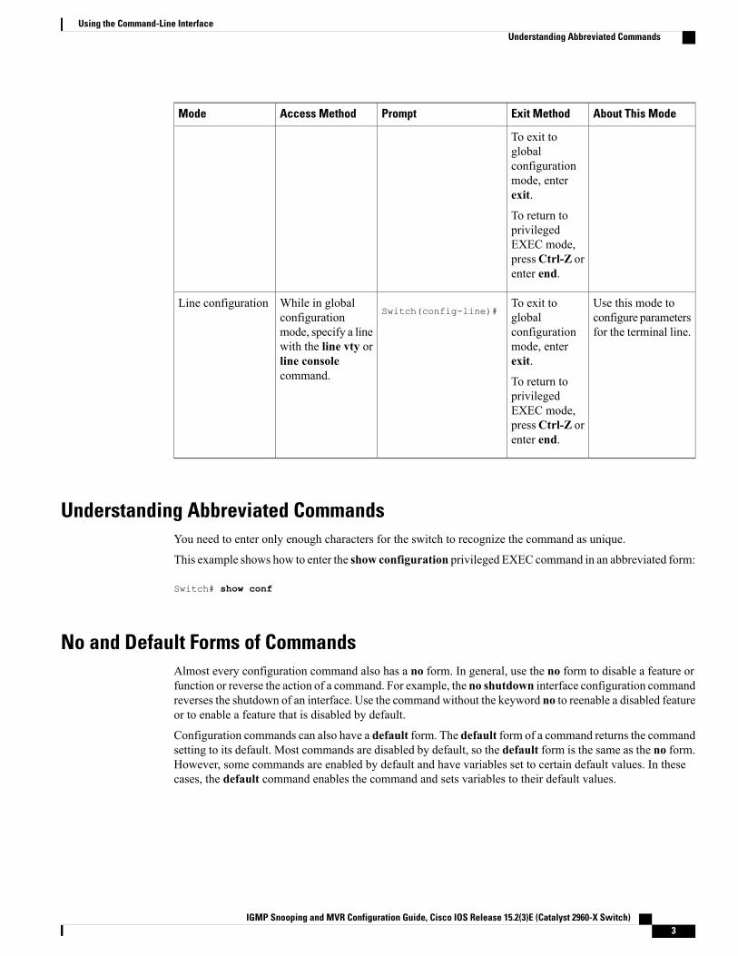
About This ModeExit MethodPromptAccess MethodMode
To exit toglobalconfigurationmode, enterexit.
To return toprivilegedEXEC mode,pressCtrl-Z orenter end.
Use this mode toconfigure parametersfor the terminal line.
To exit toglobalconfigurationmode, enterexit.
To return toprivilegedEXEC mode,pressCtrl-Z orenter end.
Switch(config-line)#While in globalconfigurationmode, specify a linewith the line vty orline consolecommand.
Line configuration
Understanding Abbreviated CommandsYou need to enter only enough characters for the switch to recognize the command as unique.
This example shows how to enter the show configuration privileged EXEC command in an abbreviated form:
Switch# show conf
No and Default Forms of CommandsAlmost every configuration command also has a no form. In general, use the no form to disable a feature orfunction or reverse the action of a command. For example, the no shutdown interface configuration commandreverses the shutdown of an interface. Use the command without the keyword no to reenable a disabled featureor to enable a feature that is disabled by default.
Configuration commands can also have a default form. The default form of a command returns the commandsetting to its default. Most commands are disabled by default, so the default form is the same as the no form.However, some commands are enabled by default and have variables set to certain default values. In thesecases, the default command enables the command and sets variables to their default values.
IGMP Snooping and MVR Configuration Guide, Cisco IOS Release 15.2(3)E (Catalyst 2960-X Switch) 3
Using the Command-Line InterfaceUnderstanding Abbreviated Commands
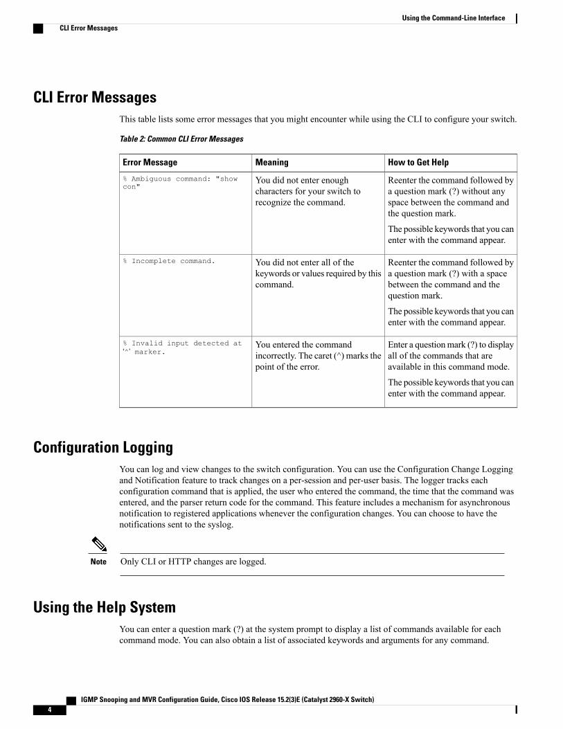
CLI Error MessagesThis table lists some error messages that you might encounter while using the CLI to configure your switch.
Table 2: Common CLI Error Messages
How to Get HelpMeaningError Message
Reenter the command followed bya question mark (?) without anyspace between the command andthe question mark.
The possible keywords that you canenter with the command appear.
You did not enter enoughcharacters for your switch torecognize the command.
% Ambiguous command: "showcon"
Reenter the command followed bya question mark (?) with a spacebetween the command and thequestion mark.
The possible keywords that you canenter with the command appear.
You did not enter all of thekeywords or values required by thiscommand.
% Incomplete command.
Enter a questionmark (?) to displayall of the commands that areavailable in this command mode.
The possible keywords that you canenter with the command appear.
You entered the commandincorrectly. The caret (^) marks thepoint of the error.
% Invalid input detected at‘^’ marker.
Configuration LoggingYou can log and view changes to the switch configuration. You can use the Configuration Change Loggingand Notification feature to track changes on a per-session and per-user basis. The logger tracks eachconfiguration command that is applied, the user who entered the command, the time that the command wasentered, and the parser return code for the command. This feature includes a mechanism for asynchronousnotification to registered applications whenever the configuration changes. You can choose to have thenotifications sent to the syslog.
Only CLI or HTTP changes are logged.Note
Using the Help SystemYou can enter a question mark (?) at the system prompt to display a list of commands available for eachcommand mode. You can also obtain a list of associated keywords and arguments for any command.
IGMP Snooping and MVR Configuration Guide, Cisco IOS Release 15.2(3)E (Catalyst 2960-X Switch)4
Using the Command-Line InterfaceCLI Error Messages
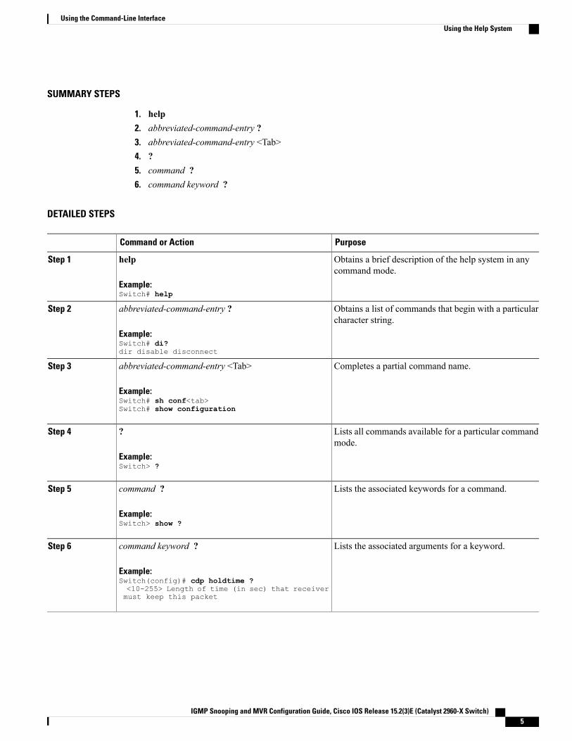
SUMMARY STEPS
1. help2. abbreviated-command-entry ?3. abbreviated-command-entry <Tab>4. ?5. command ?6. command keyword ?
DETAILED STEPS
PurposeCommand or Action
Obtains a brief description of the help system in anycommand mode.
help
Example:Switch# help
Step 1
Obtains a list of commands that begin with a particularcharacter string.
abbreviated-command-entry ?
Example:Switch# di?dir disable disconnect
Step 2
Completes a partial command name.abbreviated-command-entry <Tab>
Example:Switch# sh conf<tab>Switch# show configuration
Step 3
Lists all commands available for a particular commandmode.
?
Example:Switch> ?
Step 4
Lists the associated keywords for a command.command ?
Example:Switch> show ?
Step 5
Lists the associated arguments for a keyword.command keyword ?
Example:Switch(config)# cdp holdtime ?<10-255> Length of time (in sec) that receiver
Step 6
must keep this packet
IGMP Snooping and MVR Configuration Guide, Cisco IOS Release 15.2(3)E (Catalyst 2960-X Switch) 5
Using the Command-Line InterfaceUsing the Help System
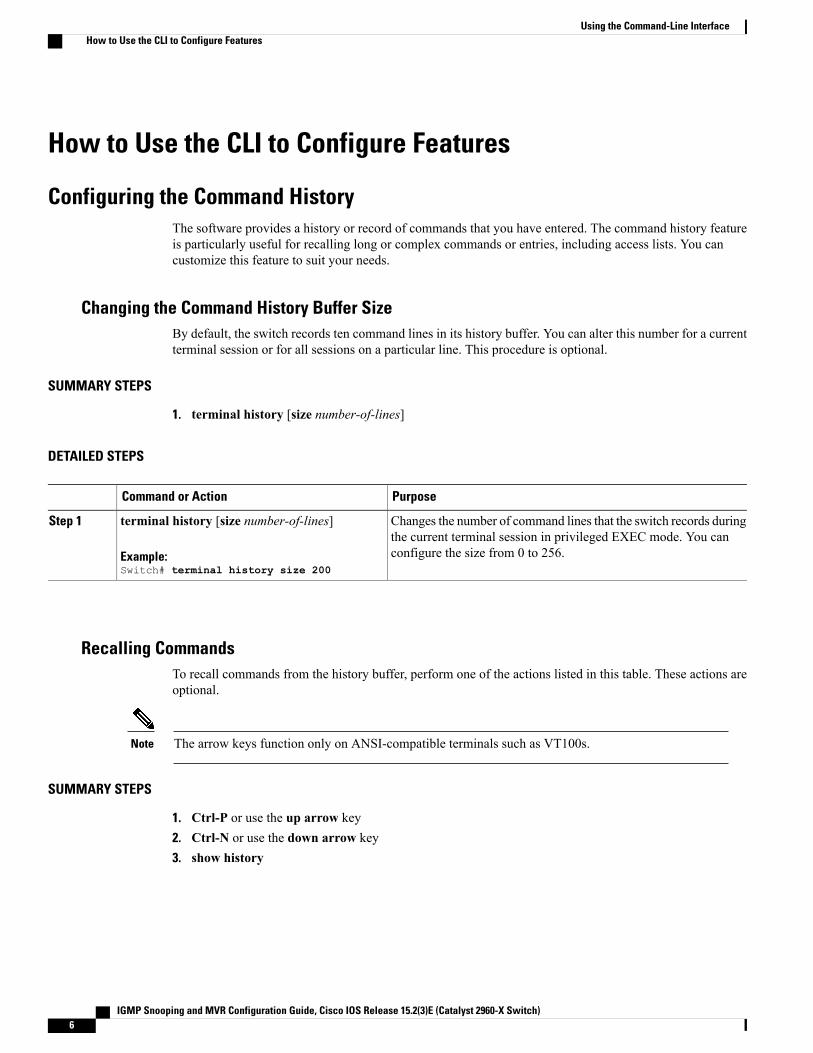
How to Use the CLI to Configure Features
Configuring the Command HistoryThe software provides a history or record of commands that you have entered. The command history featureis particularly useful for recalling long or complex commands or entries, including access lists. You cancustomize this feature to suit your needs.
Changing the Command History Buffer SizeBy default, the switch records ten command lines in its history buffer. You can alter this number for a currentterminal session or for all sessions on a particular line. This procedure is optional.
SUMMARY STEPS
1. terminal history [size number-of-lines]
DETAILED STEPS
PurposeCommand or Action
Changes the number of command lines that the switch records duringthe current terminal session in privileged EXEC mode. You canconfigure the size from 0 to 256.
terminal history [size number-of-lines]
Example:Switch# terminal history size 200
Step 1
Recalling CommandsTo recall commands from the history buffer, perform one of the actions listed in this table. These actions areoptional.
The arrow keys function only on ANSI-compatible terminals such as VT100s.Note
SUMMARY STEPS
1. Ctrl-P or use the up arrow key2. Ctrl-N or use the down arrow key3. show history
IGMP Snooping and MVR Configuration Guide, Cisco IOS Release 15.2(3)E (Catalyst 2960-X Switch)6
Using the Command-Line InterfaceHow to Use the CLI to Configure Features
DETAILED STEPS
PurposeCommand or Action
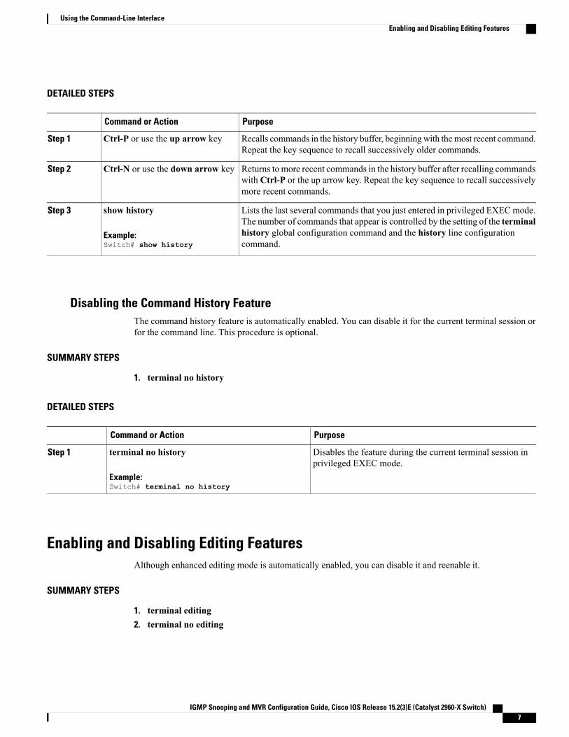
Recalls commands in the history buffer, beginningwith themost recent command.Repeat the key sequence to recall successively older commands.
Ctrl-P or use the up arrow keyStep 1
Returns to more recent commands in the history buffer after recalling commandswith Ctrl-P or the up arrow key. Repeat the key sequence to recall successivelymore recent commands.
Ctrl-N or use the down arrow keyStep 2
Lists the last several commands that you just entered in privileged EXEC mode.The number of commands that appear is controlled by the setting of the terminal
show history
Example:Switch# show history
Step 3
history global configuration command and the history line configurationcommand.
Disabling the Command History FeatureThe command history feature is automatically enabled. You can disable it for the current terminal session orfor the command line. This procedure is optional.
SUMMARY STEPS
1. terminal no history
DETAILED STEPS
PurposeCommand or Action
Disables the feature during the current terminal session inprivileged EXEC mode.
terminal no history
Example:Switch# terminal no history
Step 1
Enabling and Disabling Editing FeaturesAlthough enhanced editing mode is automatically enabled, you can disable it and reenable it.
SUMMARY STEPS
1. terminal editing2. terminal no editing
IGMP Snooping and MVR Configuration Guide, Cisco IOS Release 15.2(3)E (Catalyst 2960-X Switch) 7
Using the Command-Line InterfaceEnabling and Disabling Editing Features
DETAILED STEPS
PurposeCommand or Action
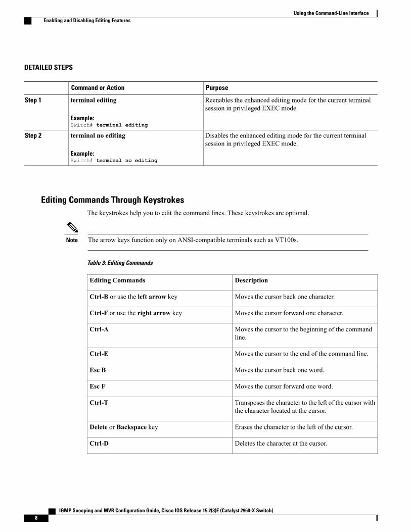
Reenables the enhanced editing mode for the current terminalsession in privileged EXEC mode.
terminal editing
Example:Switch# terminal editing
Step 1
Disables the enhanced editing mode for the current terminalsession in privileged EXEC mode.
terminal no editing
Example:Switch# terminal no editing
Step 2
Editing Commands Through KeystrokesThe keystrokes help you to edit the command lines. These keystrokes are optional.
The arrow keys function only on ANSI-compatible terminals such as VT100s.Note
Table 3: Editing Commands
DescriptionEditing Commands
Moves the cursor back one character.Ctrl-B or use the left arrow key
Moves the cursor forward one character.Ctrl-F or use the right arrow key
Moves the cursor to the beginning of the commandline.
Ctrl-A
Moves the cursor to the end of the command line.Ctrl-E
Moves the cursor back one word.Esc B
Moves the cursor forward one word.Esc F
Transposes the character to the left of the cursor withthe character located at the cursor.
Ctrl-T
Erases the character to the left of the cursor.Delete or Backspace key
Deletes the character at the cursor.Ctrl-D
IGMP Snooping and MVR Configuration Guide, Cisco IOS Release 15.2(3)E (Catalyst 2960-X Switch)8
Using the Command-Line InterfaceEnabling and Disabling Editing Features
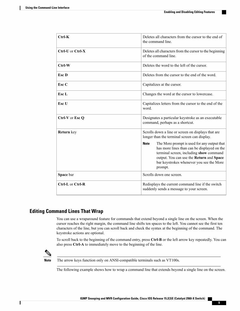
Deletes all characters from the cursor to the end ofthe command line.
Ctrl-K
Deletes all characters from the cursor to the beginningof the command line.
Ctrl-U or Ctrl-X
Deletes the word to the left of the cursor.Ctrl-W
Deletes from the cursor to the end of the word.Esc D
Capitalizes at the cursor.Esc C
Changes the word at the cursor to lowercase.Esc L
Capitalizes letters from the cursor to the end of theword.
Esc U
Designates a particular keystroke as an executablecommand, perhaps as a shortcut.
Ctrl-V or Esc Q
Scrolls down a line or screen on displays that arelonger than the terminal screen can display.
TheMore prompt is used for any output thathas more lines than can be displayed on theterminal screen, including show commandoutput. You can use the Return and Spacebar keystrokes whenever you see the Moreprompt.
Note
Return key
Scrolls down one screen.Space bar
Redisplays the current command line if the switchsuddenly sends a message to your screen.
Ctrl-L or Ctrl-R
Editing Command Lines That WrapYou can use a wraparound feature for commands that extend beyond a single line on the screen. When thecursor reaches the right margin, the command line shifts ten spaces to the left. You cannot see the first tencharacters of the line, but you can scroll back and check the syntax at the beginning of the command. Thekeystroke actions are optional.
To scroll back to the beginning of the command entry, press Ctrl-B or the left arrow key repeatedly. You canalso press Ctrl-A to immediately move to the beginning of the line.
The arrow keys function only on ANSI-compatible terminals such as VT100s.Note
The following example shows how to wrap a command line that extends beyond a single line on the screen.
IGMP Snooping and MVR Configuration Guide, Cisco IOS Release 15.2(3)E (Catalyst 2960-X Switch) 9
Using the Command-Line InterfaceEnabling and Disabling Editing Features
SUMMARY STEPS
1. access-list2. Ctrl-A3. Return key
DETAILED STEPS
PurposeCommand or Action
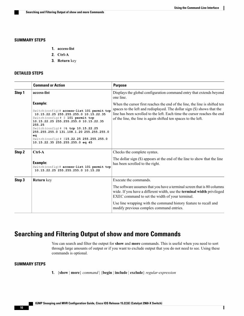
Displays the global configuration command entry that extends beyondone line.
access-list
Example:
Switch(config)# access-list 101 permit tcp
Step 1
When the cursor first reaches the end of the line, the line is shifted tenspaces to the left and redisplayed. The dollar sign ($) shows that theline has been scrolled to the left. Each time the cursor reaches the endof the line, the line is again shifted ten spaces to the left.
10.15.22.25 255.255.255.0 10.15.22.35Switch(config)# $ 101 permit tcp10.15.22.25 255.255.255.0 10.15.22.35255.25Switch(config)# $t tcp 10.15.22.25255.255.255.0 131.108.1.20 255.255.255.0eqSwitch(config)# $15.22.25 255.255.255.010.15.22.35 255.255.255.0 eq 45
Checks the complete syntax.Ctrl-AStep 2
Example:Switch(config)# access-list 101 permit tcp10.15.22.25 255.255.255.0 10.15.2$
The dollar sign ($) appears at the end of the line to show that the linehas been scrolled to the right.
Execute the commands.Return keyStep 3
The software assumes that you have a terminal screen that is 80 columnswide. If you have a different width, use the terminal width privilegedEXEC command to set the width of your terminal.
Use line wrapping with the command history feature to recall andmodify previous complex command entries.
Searching and Filtering Output of show and more CommandsYou can search and filter the output for show andmore commands. This is useful when you need to sortthrough large amounts of output or if you want to exclude output that you do not need to see. Using thesecommands is optional.
SUMMARY STEPS
1. {show |more} command | {begin | include | exclude} regular-expression
IGMP Snooping and MVR Configuration Guide, Cisco IOS Release 15.2(3)E (Catalyst 2960-X Switch)10
Using the Command-Line InterfaceSearching and Filtering Output of show and more Commands
DETAILED STEPS
PurposeCommand or Action
Searches and filters the output.{show |more} command | {begin | include | exclude}regular-expression
Step 1
Expressions are case sensitive. For example, if you enter| exclude output, the lines that contain output are notdisplayed, but the lines that contain output appear.Example:
Switch# show interfaces | include protocolVlan1 is up, line protocol is upVlan10 is up, line protocol is downGigabitEthernet1/0/1 is up, line protocol is downGigabitEthernet1/0/2 is up, line protocol is up
Accessing the CLI on a Switch StackYou can access the CLI through a console connection, through Telnet, a SSH, or by using the browser.
You manage the switch stack and the stack member interfaces through the active switchstack master. Youcannot manage stack members on an individual switch basis. You can connect to the active switchstack masterthrough the console port or the Ethernet management port of one or more stack members. Be careful withusing multiple CLI sessions on the active switchstack master. Commands that you enter in one session arenot displayed in the other sessions. Therefore, it is possible to lose track of the session fromwhich you enteredcommands.
We recommend using one CLI session when managing the switch stack.Note
If you want to configure a specific stack member port, you must include the stack member number in the CLIcommand interface notation.
To debug a specific stack member, you can start a CLI session from the stack master by using the sessionstack-member-number privileged EXEC command. The stack member number is appended to the systemprompt. For example, Switch-2# is the prompt for stack member 2 where the system prompt for the stackmaster is Switch. Only the show and debug commands are available in a CLI session to a specific stackmember. You can also use the remote command stack-member-number LINE privileged EXEC commandon the stack master to enable debugging on a member switch without first starting a session.
Accessing the CLI Through a Console Connection or Through TelnetBefore you can access the CLI, you must connect a terminal or a PC to the switch console or connect a PC tothe Ethernet management port and then power on the switch, as described in the hardware installation guidethat shipped with your switch.
If your switch is already configured, you can access the CLI through a local console connection or through aremote Telnet session, but your switch must first be configured for this type of access.
You can use one of these methods to establish a connection with the switch:
IGMP Snooping and MVR Configuration Guide, Cisco IOS Release 15.2(3)E (Catalyst 2960-X Switch) 11
Using the Command-Line InterfaceAccessing the CLI on a Switch Stack
• Connect the switch console port to a management station or dial-up modem, or connect the Ethernetmanagement port to a PC. For information about connecting to the console or Ethernet managementport, see the switch hardware installation guide.
• Use any Telnet TCP/IP or encrypted Secure Shell (SSH) package from a remote management station.The switch must have network connectivity with the Telnet or SSH client, and the switch must have anenable secret password configured.
• The switch supports up to 16 simultaneous Telnet sessions. Changes made by one Telnet user arereflected in all other Telnet sessions.
• The switch supports up to five simultaneous secure SSH sessions.
After you connect through the console port, through the Ethernet management port, through a Telnetsession or through an SSH session, the user EXEC prompt appears on the management station.
IGMP Snooping and MVR Configuration Guide, Cisco IOS Release 15.2(3)E (Catalyst 2960-X Switch)12
Using the Command-Line InterfaceAccessing the CLI Through a Console Connection or Through Telnet
C H A P T E R 2Configuring IGMP Snooping and Multicast VLANRegistration
• Finding Feature Information, page 13
• Prerequisites for Configuring IGMP Snooping and MVR, page 13
• Restrictions for Configuring IGMP Snooping and MVR, page 14
• Information About IGMP Snooping and MVR, page 16
• How to Configure IGMP Snooping and MVR, page 26
• Monitoring IGMP Snooping and MVR, page 57
• Configuration Examples for IGMP Snooping and MVR, page 59
• Additional References, page 62
• Feature History and Information for IGMP Snooping, page 63
Finding Feature InformationYour software release may not support all the features documented in this module. For the latest caveats andfeature information, see Bug Search Tool and the release notes for your platform and software release. Tofind information about the features documented in this module, and to see a list of the releases in which eachfeature is supported, see the feature information table.
Use Cisco Feature Navigator to find information about platform support and Cisco software image support.To access Cisco Feature Navigator, go to www.cisco.com/go/cfn. An account on Cisco.com is not required.
Prerequisites for Configuring IGMP Snooping and MVR
Prerequisites for IGMP SnoopingObserve these guidelines when configuring the IGMP snooping querier:
IGMP Snooping and MVR Configuration Guide, Cisco IOS Release 15.2(3)E (Catalyst 2960-X Switch) 13
• Configure the VLAN in global configuration mode.
• Configure an IP address on the VLAN interface. When enabled, the IGMP snooping querier uses the IPaddress as the query source address.
• If there is no IP address configured on the VLAN interface, the IGMP snooping querier tries to use theconfigured global IP address for the IGMP querier. If there is no global IP address specified, the IGMPquerier tries to use the VLAN switch virtual interface (SVI) IP address (if one exists). If there is no SVIIP address, the switch uses the first available IP address configured on the switch. The first IP addressavailable appears in the output of the show ip interface privileged EXEC command. The IGMP snoopingquerier does not generate an IGMP general query if it cannot find an available IP address on the switch.
• The IGMP snooping querier supports IGMP Versions 1 and 2.
•When administratively enabled, the IGMP snooping querier moves to the nonquerier state if it detectsthe presence of a multicast router in the network.
•When it is administratively enabled, the IGMP snooping querier moves to the operationally disabledstate under these conditions:
◦IGMP snooping is disabled in the VLAN.
◦PIM is enabled on the SVI of the corresponding VLAN.
Related Topics
Configuring the IGMP Snooping Querier , on page 41
IGMP Snooping, on page 16
Prerequisites for MVRThe following are the prerequisites for Multicast VLAN Registration (MVR):
• To use MVR, the switch must be running the LAN Base image.
Restrictions for Configuring IGMP Snooping and MVR
Restrictions for IGMP SnoopingThe following are the restrictions for IGMP snooping:
• The switch supports homogeneous stacking and mixed stacking. Mixed stacking is supported only withthe Catalyst 2960-S switches. A homogenous stack can have up to eight stack members, while a mixedstack can have up to four stack members. All switches in a switch stack must be running the LAN Baseimage.
• IGMPv3 join and leave messages are not supported on switches running IGMP filtering or MulticastVLAN registration (MVR).
• IGMP report suppression is supported only when the multicast query has IGMPv1 and IGMPv2 reports.This feature is not supported when the query includes IGMPv3 reports.
IGMP Snooping and MVR Configuration Guide, Cisco IOS Release 15.2(3)E (Catalyst 2960-X Switch)14
Configuring IGMP Snooping and Multicast VLAN RegistrationPrerequisites for MVR
• The IGMP configurable leave time is only supported on hosts running IGMP Version 2. IGMP version2 is the default version for the switch.
The actual leave latency in the network is usually the configured leave time. However, the leave timemight vary around the configured time, depending on real-time CPU load conditions, network delaysand the amount of traffic sent through the interface.
• The IGMP throttling action restriction can be applied only to Layer 2 ports. You can use ip igmpmax-groups action replace interface configuration command on a logical EtherChannel interface butcannot use it on ports that belong to an EtherChannel port group.
When themaximumgroup limitation is set to the default (nomaximum), entering the ip igmpmax-groupsaction {deny | replace} command has no effect.
If you configure the throttling action and set the maximum group limitation after an interface has addedmulticast entries to the forwarding table, the forwarding-table entries are either aged out or removed,depending on the throttling action.
Related Topics
IGMP Versions, on page 17
Configuring IGMP Profiles , on page 49
Applying IGMP Profiles , on page 52
Setting the Maximum Number of IGMP Groups , on page 53
Configuring the IGMP Throttling Action , on page 55
IGMP Filtering and Throttling, on page 25
Restrictions for MVRThe following are restrictions for MVR:
• Only Layer 2 ports participate in MVR. You must configure ports as MVR receiver ports.
• Only one MVR multicast VLAN per switch or switch stack is supported.
• Receiver ports can only be access ports; they cannot be trunk ports. Receiver ports on a switch can bein different VLANs, but should not belong to the multicast VLAN.
• The maximum number of multicast entries (MVR group addresses) that can be configured on a switch(that is, the maximum number of television channels that can be received) is 256.
• MVR multicast data received in the source VLAN and leaving from receiver ports has its time-to-live(TTL) decremented by 1 in the switch.
• Because MVR on the switch uses IP multicast addresses instead of MAC multicast addresses, alias IPmulticast addresses are allowed on the switch. However, if the switch is interoperating with Catalyst3550 or Catalyst 3500 XL switches, you should not configure IP addresses that alias between themselvesor with the reserved IP multicast addresses (in the range 224.0.0.xxx).
• Do not configure MVR on private VLAN ports.
• MVR is not supported when multicast routing is enabled on a switch. If you enable multicast routingand a multicast routing protocol while MVR is enabled, MVR is disabled, and you receive a warning
IGMP Snooping and MVR Configuration Guide, Cisco IOS Release 15.2(3)E (Catalyst 2960-X Switch) 15
Configuring IGMP Snooping and Multicast VLAN RegistrationRestrictions for MVR
message. If you try to enable MVRwhile multicast routing and a multicast routing protocol are enabled,the operation to enable MVR is cancelled, and you receive an error message
• MVR data received on an MVR receiver port is not forwarded to MVR source ports.
• MVR does not support IGMPv3 messages.
• The switch supports homogeneous stacking and mixed stacking. Mixed stacking is supported only withthe Catalyst 2960-S switches. A homogenous stack can have up to eight stack members, while a mixedstack can have up to four stack members. All switches in a switch stack must be running the LAN Baseimage.
Information About IGMP Snooping and MVR
IGMP SnoopingLayer 2 switches can use IGMP snooping to constrain the flooding of multicast traffic by dynamicallyconfiguring Layer 2 interfaces so that multicast traffic is forwarded to only those interfaces associated withIP multicast devices. As the name implies, IGMP snooping requires the LAN switch to snoop on the IGMPtransmissions between the host and the router and to keep track of multicast groups and member ports. Whenthe switch receives an IGMP report from a host for a particular multicast group, the switch adds the host portnumber to the forwarding table entry; when it receives an IGMP Leave Groupmessage from a host, it removesthe host port from the table entry. It also periodically deletes entries if it does not receive IGMP membershipreports from the multicast clients.
For more information on IP multicast and IGMP, see RFC 1112 and RFC 2236.Note
The multicast router ) sends out periodic general queries to all VLANs. All hosts interested in this multicasttraffic send join requests and are added to the forwarding table entry. The switch creates one entry per VLANin the IGMP snooping IP multicast forwarding table for each group from which it receives an IGMP joinrequest.
The switch supports IP multicast group-based bridging, instead of MAC-addressed based groups. Withmulticast MAC address-based groups, if an IP address being configured translates (aliases) to a previouslyconfiguredMAC address or to any reservedmulticastMAC addresses (in the range 224.0.0.xxx), the commandfails. Because the switch uses IP multicast groups, there are no address aliasing issues.
The IP multicast groups learned through IGMP snooping are dynamic. However, you can statically configuremulticast groups by using the ip igmp snooping vlan vlan-id static ip_address interface interface-id globalconfiguration command. If you specify group membership for a multicast group address statically, your settingsupersedes any automatic manipulation by IGMP snooping. Multicast group membership lists can consist ofboth user-defined and IGMP snooping-learned settings.
You can configure an IGMP snooping querier to support IGMP snooping in subnets without multicast interfacesbecause the multicast traffic does not need to be routed.
If a port spanning-tree, a port group, or a VLAN ID change occurs, the IGMP snooping-learned multicastgroups from this port on the VLAN are deleted.
These sections describe IGMP snooping characteristics:
IGMP Snooping and MVR Configuration Guide, Cisco IOS Release 15.2(3)E (Catalyst 2960-X Switch)16
Configuring IGMP Snooping and Multicast VLAN RegistrationInformation About IGMP Snooping and MVR
Related Topics
Configuring the IGMP Snooping Querier , on page 41
Prerequisites for IGMP Snooping, on page 13
Example: Setting the IGMP Snooping Querier Source Address, on page 60Example: Setting the IGMP Snooping Querier Maximum Response Time, on page 60Example: Setting the IGMP Snooping Querier Timeout, on page 61Example: Setting the IGMP Snooping Querier Feature, on page 61
IGMP VersionsThe switch supports IGMP version 1, IGMP version 2, and IGMP version 3. These versions are interoperableon the switch. For example, if IGMP snooping is enabled and the querier's version is IGMPv2, and the switchreceives an IGMPv3 report from a host, then the switch can forward the IGMPv3 report to the multicast router.
An IGMPv3 switch can receive messages from and forward messages to a device running the Source SpecificMulticast (SSM) feature.
Related Topics
Restrictions for IGMP Snooping, on page 14
Joining a Multicast Group
When a host connected to the switch wants to join an IP multicast group and it is an IGMP version 2 client,it sends an unsolicited IGMP join message, specifying the IP multicast group to join. Alternatively, when theswitch receives a general query from the router, it forwards the query to all ports in the VLAN. IGMP version1 or version 2 hosts wanting to join the multicast group respond by sending a join message to the switch. Theswitch CPU creates a multicast forwarding-table entry for the group if it is not already present. The CPU alsoadds the interface where the join message was received to the forwarding-table entry. The host associatedwith that interface receives multicast traffic for that multicast group.
IGMP Snooping and MVR Configuration Guide, Cisco IOS Release 15.2(3)E (Catalyst 2960-X Switch) 17
Configuring IGMP Snooping and Multicast VLAN RegistrationIGMP Snooping
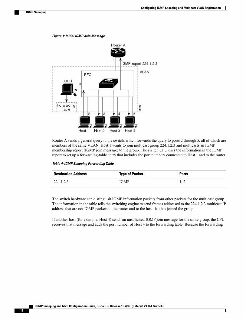
Figure 1: Initial IGMP Join Message
Router A sends a general query to the switch, which forwards the query to ports 2 through 5, all of which aremembers of the same VLAN. Host 1 wants to join multicast group 224.1.2.3 and multicasts an IGMPmembership report (IGMP join message) to the group. The switch CPU uses the information in the IGMPreport to set up a forwarding-table entry that includes the port numbers connected to Host 1 and to the router.
Table 4: IGMP Snooping Forwarding Table
PortsType of PacketDestination Address
1, 2IGMP224.1.2.3
The switch hardware can distinguish IGMP information packets from other packets for the multicast group.The information in the table tells the switching engine to send frames addressed to the 224.1.2.3 multicast IPaddress that are not IGMP packets to the router and to the host that has joined the group.
If another host (for example, Host 4) sends an unsolicited IGMP join message for the same group, the CPUreceives that message and adds the port number of Host 4 to the forwarding table. Because the forwarding
IGMP Snooping and MVR Configuration Guide, Cisco IOS Release 15.2(3)E (Catalyst 2960-X Switch)18
Configuring IGMP Snooping and Multicast VLAN RegistrationIGMP Snooping
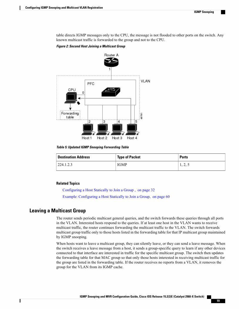
table directs IGMP messages only to the CPU, the message is not flooded to other ports on the switch. Anyknown multicast traffic is forwarded to the group and not to the CPU.Figure 2: Second Host Joining a Multicast Group
Table 5: Updated IGMP Snooping Forwarding Table
PortsType of PacketDestination Address
1, 2, 5IGMP224.1.2.3
Related Topics
Configuring a Host Statically to Join a Group , on page 32
Example: Configuring a Host Statically to Join a Group, on page 60
Leaving a Multicast GroupThe router sends periodic multicast general queries, and the switch forwards these queries through all portsin the VLAN. Interested hosts respond to the queries. If at least one host in the VLAN wants to receivemulticast traffic, the router continues forwarding the multicast traffic to the VLAN. The switch forwardsmulticast group traffic only to those hosts listed in the forwarding table for that IP multicast group maintainedby IGMP snooping.
When hosts want to leave a multicast group, they can silently leave, or they can send a leave message. Whenthe switch receives a leave message from a host, it sends a group-specific query to learn if any other devicesconnected to that interface are interested in traffic for the specific multicast group. The switch then updatesthe forwarding table for that MAC group so that only those hosts interested in receiving multicast traffic forthe group are listed in the forwarding table. If the router receives no reports from a VLAN, it removes thegroup for the VLAN from its IGMP cache.
IGMP Snooping and MVR Configuration Guide, Cisco IOS Release 15.2(3)E (Catalyst 2960-X Switch) 19
Configuring IGMP Snooping and Multicast VLAN RegistrationIGMP Snooping
Immediate LeaveThe switch uses IGMP snooping Immediate Leave to remove from the forwarding table an interface that sendsa leave message without the switch sending group-specific queries to the interface. The VLAN interface ispruned from the multicast tree for the multicast group specified in the original leave message. ImmediateLeave ensures optimal bandwidth management for all hosts on a switched network, even when multiplemulticast groups are simultaneously in use.
Immediate Leave is only supported on IGMP version 2 hosts. IGMP version 2 is the default version for theswitch.
You should use the Immediate Leave feature only on VLANs where a single host is connected to eachport. If Immediate Leave is enabled on VLANs where more than one host is connected to a port, somehosts may be dropped inadvertently.
Note
Related Topics
Enabling IGMP Immediate Leave , on page 33
Example: Enabling IGMP Immediate Leave, on page 60
IGMP Configurable-Leave TimerYou can configure the time that the switch waits after sending a group-specific query to determine if hostsare still interested in a specific multicast group. The IGMP leave response time can be configured from 100to 32767 milliseconds.
Related Topics
Configuring the IGMP Leave Timer , on page 35
IGMP Report Suppression
IGMP report suppression is supported only when the multicast query has IGMPv1 and IGMPv2 reports.This feature is not supported when the query includes IGMPv3 reports.
Note
The switch uses IGMP report suppression to forward only one IGMP report per multicast router query tomulticast devices. When IGMP report suppression is enabled (the default), the switch sends the first IGMPreport from all hosts for a group to all the multicast routers. The switch does not send the remaining IGMPreports for the group to the multicast routers. This feature prevents duplicate reports from being sent to themulticast devices.
If the multicast router query includes requests only for IGMPv1 and IGMPv2 reports, the switch forwardsonly the first IGMPv1 or IGMPv2 report from all hosts for a group to all the multicast routers.
If the multicast router query also includes requests for IGMPv3 reports, the switch forwards all IGMPv1,IGMPv2, and IGMPv3 reports for a group to the multicast devices.
If you disable IGMP report suppression, all IGMP reports are forwarded to the multicast routers.
IGMP Snooping and MVR Configuration Guide, Cisco IOS Release 15.2(3)E (Catalyst 2960-X Switch)20
Configuring IGMP Snooping and Multicast VLAN RegistrationIGMP Snooping
Related Topics
Disabling IGMP Report Suppression , on page 43
IGMP Snooping and Switch StacksIGMP snooping functions across the switch stack; that is, IGMP control information from one switch isdistributed to all switches in the stack. Regardless of the stack member through which IGMP multicast dataenters the stack, the data reaches the hosts that have registered for that group.
If a switch in the stack fails or is removed from the stack, only the members of the multicast group that areon that switch will not receive the multicast data. All other members of a multicast group on other switchesin the stack continue to receive multicast data streams. However, multicast groups that are common for bothLayer 2 and Layer 3 (IP multicast routing) might take longer to converge if the active switch is removed.
Default IGMP Snooping ConfigurationThis table displays the default IGMP snooping configuration for the switch.
Table 6: Default IGMP Snooping Configuration
Default SettingFeature
Enabled globally and per VLANIGMP snooping
None configuredMulticast routers
DisabledIGMP snooping Immediate Leave
None configuredStatic groups
2TCN1 flood query count
DisabledTCN query solicitation
DisabledIGMP snooping querier
EnabledIGMP report suppression
1 (1) TCN = Topology Change Notification
Related Topics
Enabling or Disabling IGMP Snooping on a Switch , on page 26
Enabling or Disabling IGMP Snooping on a VLAN Interface, on page 27
IGMP Snooping and MVR Configuration Guide, Cisco IOS Release 15.2(3)E (Catalyst 2960-X Switch) 21
Configuring IGMP Snooping and Multicast VLAN RegistrationIGMP Snooping
Multicast VLAN RegistrationMulticast VLAN Registration (MVR) is designed for applications using wide-scale deployment of multicasttraffic across an Ethernet ring-based service-provider network (for example, the broadcast of multiple televisionchannels over a service-provider network). MVR allows a subscriber on a port to subscribe and unsubscribeto a multicast stream on the network-wide multicast VLAN. It allows the single multicast VLAN to be sharedin the network while subscribers remain in separate VLANs. MVR provides the ability to continuously sendmulticast streams in the multicast VLAN, but to isolate the streams from the subscriber VLANs for bandwidthand security reasons.
These sections describe MVR:
MVR and IGMP
MVR can coexist with IGMP snooping on a switch.Note
MVR assumes that subscriber ports subscribe and unsubscribe (join and leave) these multicast streams bysending out IGMP join and leavemessages. These messages can originate from an IGMP version-2-compatiblehost with an Ethernet connection. Although MVR operates on the underlying method of IGMP snooping, thetwo features operate independently of each other. One can be enabled or disabled without affecting the behaviorof the other feature. However, if IGMP snooping and MVR are both enabled, MVR reacts only to join andleavemessages frommulticast groups configured underMVR. Join and leavemessages from all other multicastgroups are managed by IGMP snooping.
The switch CPU identifies the MVR IP multicast streams and their associated IP multicast group in the switchforwarding table, intercepts the IGMP messages, and modifies the forwarding table to include or remove thesubscriber as a receiver of the multicast stream, even though the receivers might be in a different VLAN fromthe source. This forwarding behavior selectively allows traffic to cross between different VLANs.
Modes of OperationYou can set the switch for compatible or dynamic mode of MVR operation:
• In compatible mode, multicast data received byMVR hosts is forwarded to all MVR data ports, regardlessof MVR host membership on those ports. The multicast data is forwarded only to those receiver portsthat MVR hosts have joined, either by IGMP reports or by MVR static configuration. IGMP reportsreceived fromMVR hosts are never forwarded fromMVR data ports that were configured in the switch.
• In dynamic mode, multicast data received by MVR hosts on the switch is forwarded from only thoseMVR data and client ports that the MVR hosts have joined, either by IGMP reports or by MVR staticconfiguration. Any IGMP reports received from MVR hosts are also forwarded from all the MVR dataports in the host. This eliminates using unnecessary bandwidth on MVR data port links, which occurswhen the switch runs in compatible mode.
MVR and Switch StacksOnly one MVR multicast VLAN per switch or switch stack is supported.
IGMP Snooping and MVR Configuration Guide, Cisco IOS Release 15.2(3)E (Catalyst 2960-X Switch)22
Configuring IGMP Snooping and Multicast VLAN RegistrationMulticast VLAN Registration
Receiver ports and source ports can be on different switches in a switch stack. Multicast data sent on themulticast VLAN is forwarded to all MVR receiver ports across the stack. When a new switch is added to astack, by default it has no receiver ports.
If a switch fails or is removed from the stack, only those receiver ports belonging to that switch will not receivethe multicast data. All other receiver ports on other switches continue to receive the multicast data.
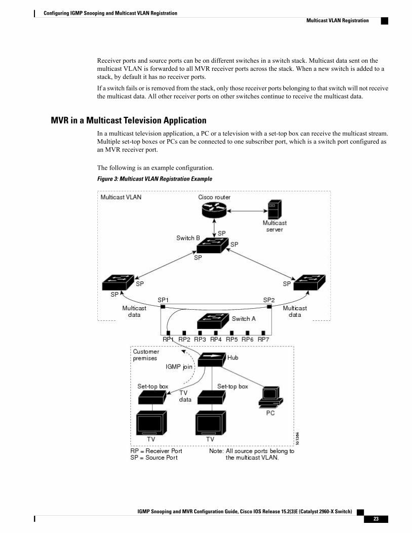
MVR in a Multicast Television ApplicationIn a multicast television application, a PC or a television with a set-top box can receive the multicast stream.Multiple set-top boxes or PCs can be connected to one subscriber port, which is a switch port configured asan MVR receiver port.
The following is an example configuration.Figure 3: Multicast VLAN Registration Example
IGMP Snooping and MVR Configuration Guide, Cisco IOS Release 15.2(3)E (Catalyst 2960-X Switch) 23
Configuring IGMP Snooping and Multicast VLAN RegistrationMulticast VLAN Registration
In this example configuration, DHCP assigns an IP address to the set-top box or the PC. When a subscriberselects a channel, the set-top box or PC sends an IGMP report to Switch A to join the appropriate multicast.If the IGMP report matches one of the configured IP multicast group addresses, the switch CPU modifies thehardware address table to include this receiver port and VLAN as a forwarding destination of the specifiedmulticast stream when it is received from the multicast VLAN. Uplink ports that send and receive multicastdata to and from the multicast VLAN are called MVR source ports.
When a subscriber changes channels or turns off the television, the set-top box sends an IGMP leave messagefor the multicast stream. The switch CPU sends aMAC-based general query through the receiver port VLAN.If there is another set-top box in the VLAN still subscribing to this group, that set-top boxmust respond withinthe maximum response time specified in the query. If the CPU does not receive a response, it eliminates thereceiver port as a forwarding destination for this group.
Without Immediate Leave, when the switch receives an IGMP leave message from a subscriber on a receiverport, it sends out an IGMP query on that port and waits for IGMP group membership reports. If no reportsare received in a configured time period, the receiver port is removed frommulticast group membership. WithImmediate Leave, an IGMP query is not sent from the receiver port on which the IGMP leave was received.As soon as the leave message is received, the receiver port is removed from multicast group membership,which speeds up leave latency. Enable the Immediate-Leave feature only on receiver ports to which a singlereceiver device is connected.
MVR eliminates the need to duplicate television-channel multicast traffic for subscribers in each VLAN.Multicast traffic for all channels is only sent around the VLAN trunk once—only on the multicast VLAN.The IGMP leave and join messages are in the VLAN to which the subscriber port is assigned. These messagesdynamically register for streams of multicast traffic in the multicast VLAN on the Layer 3 device. The accesslayer switch, Switch A, modifies the forwarding behavior to allow the traffic to be forwarded from the multicastVLAN to the subscriber port in a different VLAN, selectively allowing traffic to cross between two VLANs.
IGMP reports are sent to the same IP multicast group address as the multicast data. The Switch A CPU mustcapture all IGMP join and leave messages from receiver ports and forward them to the multicast VLAN ofthe source (uplink) port, based on the MVR mode.
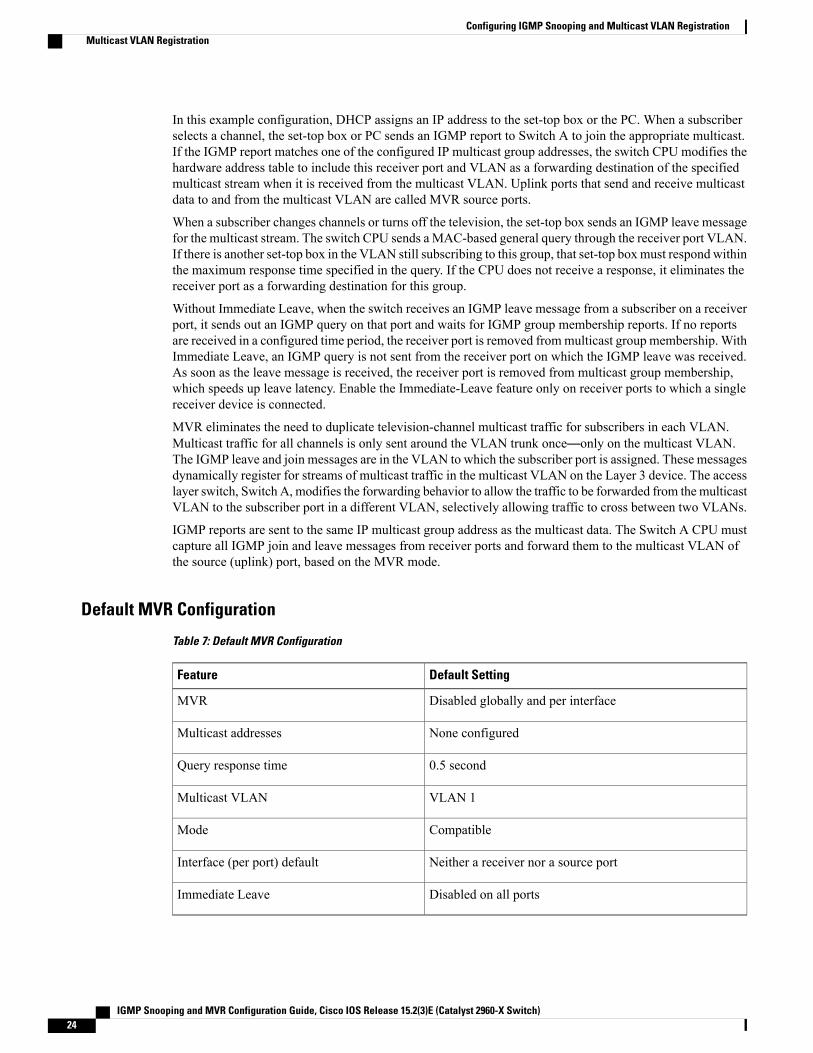
Default MVR Configuration
Table 7: Default MVR Configuration
Default SettingFeature
Disabled globally and per interfaceMVR
None configuredMulticast addresses
0.5 secondQuery response time
VLAN 1Multicast VLAN
CompatibleMode
Neither a receiver nor a source portInterface (per port) default
Disabled on all portsImmediate Leave
IGMP Snooping and MVR Configuration Guide, Cisco IOS Release 15.2(3)E (Catalyst 2960-X Switch)24
Configuring IGMP Snooping and Multicast VLAN RegistrationMulticast VLAN Registration
IGMP Filtering and ThrottlingIn some environments, for example, metropolitan or multiple-dwelling unit (MDU) installations, you mightwant to control the set of multicast groups to which a user on a switch port can belong. You can control thedistribution of multicast services, such as IP/TV, based on some type of subscription or service plan. Youmight also want to limit the number of multicast groups to which a user on a switch port can belong.
With the IGMP filtering feature, you can filter multicast joins on a per-port basis by configuring IP multicastprofiles and associating themwith individual switch ports. An IGMP profile can contain one or more multicastgroups and specifies whether access to the group is permitted or denied. If an IGMP profile denying accessto a multicast group is applied to a switch port, the IGMP join report requesting the stream of IP multicasttraffic is dropped, and the port is not allowed to receive IP multicast traffic from that group. If the filteringaction permits access to the multicast group, the IGMP report from the port is forwarded for normal processing.You can also set the maximum number of IGMP groups that a Layer 2 interface can join.
IGMP filtering controls only group-specific query and membership reports, including join and leave reports.It does not control general IGMP queries. IGMP filtering has no relationship with the function that directsthe forwarding of IP multicast traffic. The filtering feature operates in the same manner whether CGMP orMVR is used to forward the multicast traffic.
IGMP filtering applies only to the dynamic learning of IP multicast group addresses, not static configuration.
With the IGMP throttling feature, you can set the maximum number of IGMP groups that a Layer 2 interfacecan join. If the maximum number of IGMP groups is set, the IGMP snooping forwarding table contains themaximum number of entries, and the interface receives an IGMP join report, you can configure an interfaceto drop the IGMP report or to replace the randomly selected multicast entry with the received IGMP report.
IGMPv3 join and leave messages are not supported on switches running IGMP filtering.Note
Related Topics
Configuring IGMP Profiles , on page 49
Applying IGMP Profiles , on page 52
Setting the Maximum Number of IGMP Groups , on page 53
Configuring the IGMP Throttling Action , on page 55
Restrictions for IGMP Snooping, on page 14
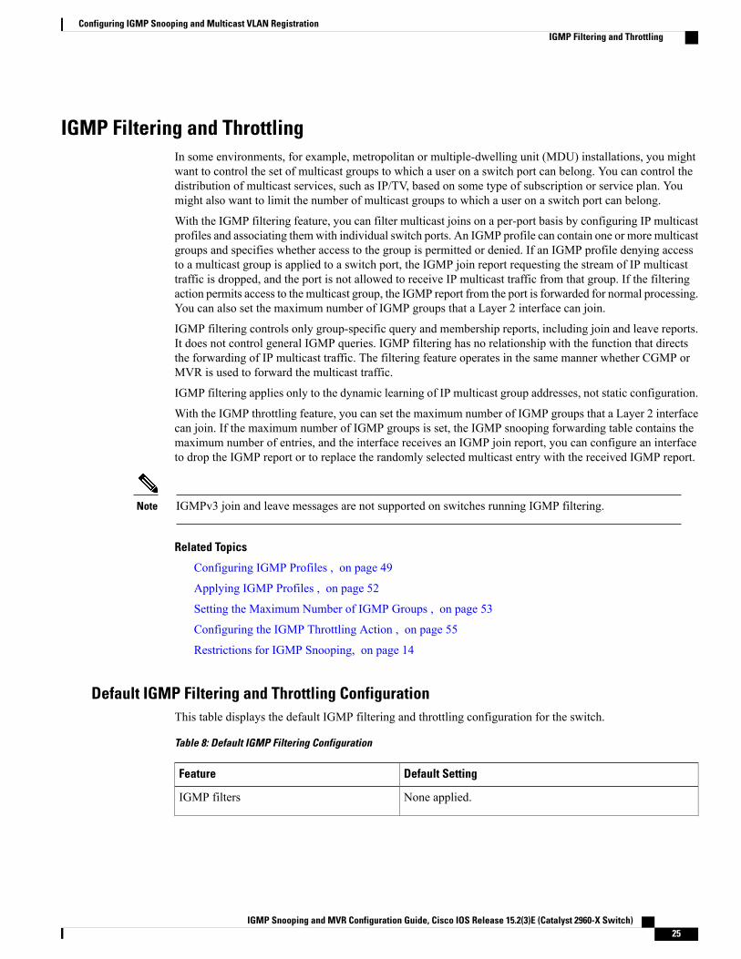
Default IGMP Filtering and Throttling ConfigurationThis table displays the default IGMP filtering and throttling configuration for the switch.
Table 8: Default IGMP Filtering Configuration
Default SettingFeature
None applied.IGMP filters
IGMP Snooping and MVR Configuration Guide, Cisco IOS Release 15.2(3)E (Catalyst 2960-X Switch) 25
Configuring IGMP Snooping and Multicast VLAN RegistrationIGMP Filtering and Throttling
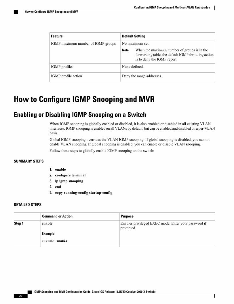
Default SettingFeature
No maximum set.
When the maximum number of groups is in theforwarding table, the default IGMP throttling actionis to deny the IGMP report.
Note
IGMP maximum number of IGMP groups
None defined.IGMP profiles
Deny the range addresses.IGMP profile action
How to Configure IGMP Snooping and MVR
Enabling or Disabling IGMP Snooping on a SwitchWhen IGMP snooping is globally enabled or disabled, it is also enabled or disabled in all existing VLANinterfaces. IGMP snooping is enabled on all VLANs by default, but can be enabled and disabled on a per-VLANbasis.
Global IGMP snooping overrides the VLAN IGMP snooping. If global snooping is disabled, you cannotenable VLAN snooping. If global snooping is enabled, you can enable or disable VLAN snooping.
Follow these steps to globally enable IGMP snooping on the switch:
SUMMARY STEPS
1. enable2. configure terminal3. ip igmp snooping4. end5. copy running-config startup-config
DETAILED STEPS
PurposeCommand or Action
Enables privileged EXEC mode. Enter your password ifprompted.
enable
Example:
Switch> enable
Step 1
IGMP Snooping and MVR Configuration Guide, Cisco IOS Release 15.2(3)E (Catalyst 2960-X Switch)26
Configuring IGMP Snooping and Multicast VLAN RegistrationHow to Configure IGMP Snooping and MVR
PurposeCommand or Action
Enters the global configuration mode.configure terminal
Example:
Switch# configure terminal
Step 2
Globally enables IGMP snooping in all existing VLANinterfaces.
ip igmp snooping
Example:
Switch(config)# ip igmp snooping
Step 3
To globally disable IGMP snooping on all VLANinterfaces, use the no ip igmp snooping globalconfiguration command.
Note
Returns to privileged EXEC mode.end
Example:
Switch(config)# end
Step 4
(Optional) Saves your entries in the configuration file.copy running-config startup-config
Example:
Switch# copy running-config startup-config
Step 5
Related Topics
Default IGMP Snooping Configuration, on page 21
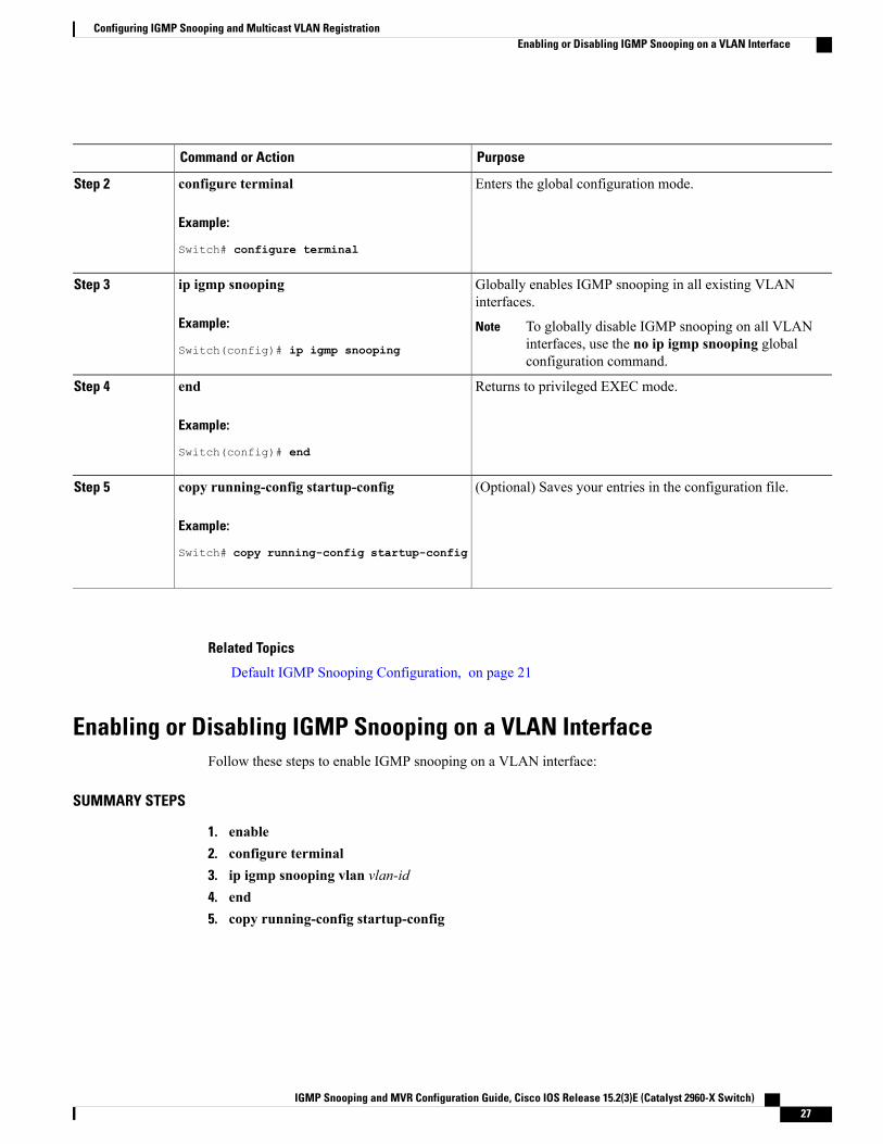
Enabling or Disabling IGMP Snooping on a VLAN InterfaceFollow these steps to enable IGMP snooping on a VLAN interface:
SUMMARY STEPS
1. enable2. configure terminal3. ip igmp snooping vlan vlan-id4. end5. copy running-config startup-config
IGMP Snooping and MVR Configuration Guide, Cisco IOS Release 15.2(3)E (Catalyst 2960-X Switch) 27
Configuring IGMP Snooping and Multicast VLAN RegistrationEnabling or Disabling IGMP Snooping on a VLAN Interface
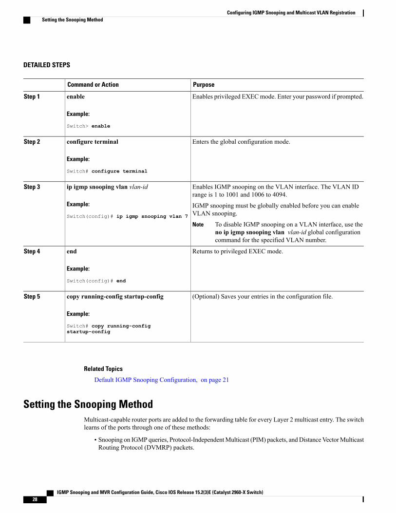
DETAILED STEPS
PurposeCommand or Action
Enables privileged EXECmode. Enter your password if prompted.enableStep 1
Example:
Switch> enable
Enters the global configuration mode.configure terminal
Example:
Switch# configure terminal
Step 2
Enables IGMP snooping on the VLAN interface. The VLAN IDrange is 1 to 1001 and 1006 to 4094.
ip igmp snooping vlan vlan-id
Example:
Switch(config)# ip igmp snooping vlan 7
Step 3
IGMP snooping must be globally enabled before you can enableVLAN snooping.
To disable IGMP snooping on a VLAN interface, use theno ip igmp snooping vlan vlan-id global configurationcommand for the specified VLAN number.
Note
Returns to privileged EXEC mode.end
Example:
Switch(config)# end
Step 4
(Optional) Saves your entries in the configuration file.copy running-config startup-config
Example:
Switch# copy running-config
Step 5
startup-config
Related Topics
Default IGMP Snooping Configuration, on page 21
Setting the Snooping MethodMulticast-capable router ports are added to the forwarding table for every Layer 2 multicast entry. The switchlearns of the ports through one of these methods:
• Snooping on IGMP queries, Protocol-IndependentMulticast (PIM) packets, andDistanceVectorMulticastRouting Protocol (DVMRP) packets.
IGMP Snooping and MVR Configuration Guide, Cisco IOS Release 15.2(3)E (Catalyst 2960-X Switch)28
Configuring IGMP Snooping and Multicast VLAN RegistrationSetting the Snooping Method
• Listening to Cisco Group Management Protocol (CGMP) packets from other routers.
• Statically connecting to a multicast router port using the ip igmp snoopingmrouter global configurationcommand.
You can configure the switch either to snoop on IGMP queries and PIM/DVMRP packets or to listen to CGMPself-join or proxy-join packets. By default, the switch snoops on PIM/DVMRP packets on all VLANs. Tolearn of multicast router ports through only CGMP packets, use the ip igmp snooping vlan vlan-id mrouterlearn cgmp global configuration command. When this command is entered, the router listens to only CGMPself-join and CGMP proxy-join packets and to no other CGMP packets. To learn of multicast router portsthrough only PIM-DVMRP packets, use the ip igmp snooping vlan vlan-id mrouter learn pim-dvmrpglobal configuration command.
If you want to use CGMP as the learning method and no multicast routers in the VLAN are CGMPproxy-enabled, you must enter the ip cgmp router-only command to dynamically access the router.
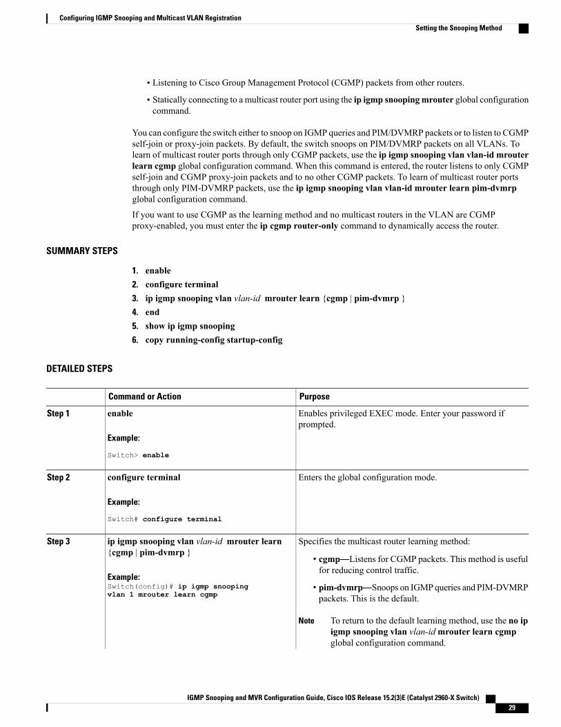
SUMMARY STEPS
1. enable2. configure terminal3. ip igmp snooping vlan vlan-id mrouter learn {cgmp | pim-dvmrp }4. end5. show ip igmp snooping6. copy running-config startup-config
DETAILED STEPS
PurposeCommand or Action
Enables privileged EXEC mode. Enter your password ifprompted.
enable
Example:
Switch> enable
Step 1
Enters the global configuration mode.configure terminal
Example:
Switch# configure terminal
Step 2
Specifies the multicast router learning method:ip igmp snooping vlan vlan-id mrouter learn{cgmp | pim-dvmrp }
Step 3
• cgmp—Listens for CGMP packets. This method is usefulfor reducing control traffic.
Example:Switch(config)# ip igmp snoopingvlan 1 mrouter learn cgmp
• pim-dvmrp—Snoops on IGMPqueries and PIM-DVMRPpackets. This is the default.
To return to the default learning method, use the no ipigmp snooping vlan vlan-idmrouter learn cgmpglobal configuration command.
Note
IGMP Snooping and MVR Configuration Guide, Cisco IOS Release 15.2(3)E (Catalyst 2960-X Switch) 29
Configuring IGMP Snooping and Multicast VLAN RegistrationSetting the Snooping Method
PurposeCommand or Action
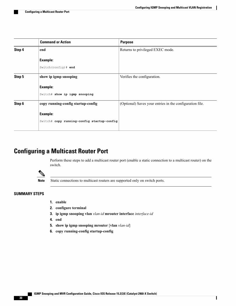
Returns to privileged EXEC mode.end
Example:
Switch(config)# end
Step 4
Verifies the configuration.show ip igmp snooping
Example:
Switch# show ip igmp snooping
Step 5
(Optional) Saves your entries in the configuration file.copy running-config startup-config
Example:
Switch# copy running-config startup-config
Step 6
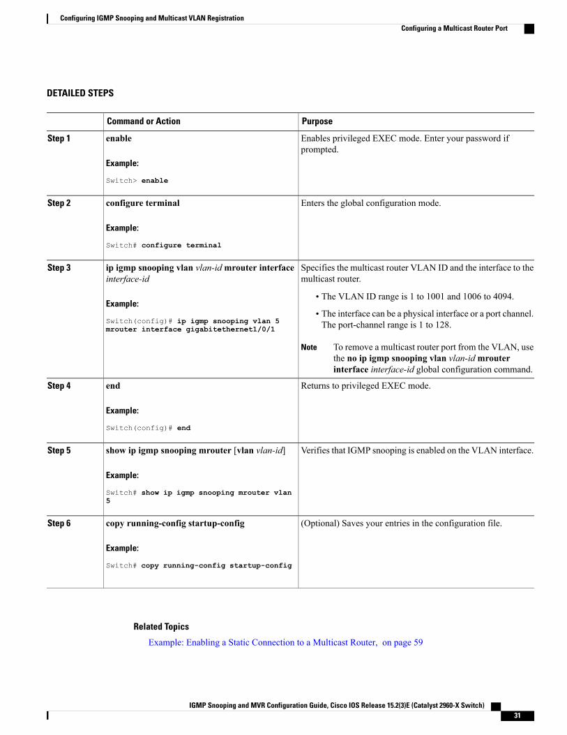
Configuring a Multicast Router PortPerform these steps to add a multicast router port (enable a static connection to a multicast router) on theswitch.
Static connections to multicast routers are supported only on switch ports.Note
SUMMARY STEPS
1. enable2. configure terminal3. ip igmp snooping vlan vlan-idmrouter interface interface-id4. end5. show ip igmp snooping mrouter [vlan vlan-id]6. copy running-config startup-config
IGMP Snooping and MVR Configuration Guide, Cisco IOS Release 15.2(3)E (Catalyst 2960-X Switch)30
Configuring IGMP Snooping and Multicast VLAN RegistrationConfiguring a Multicast Router Port
DETAILED STEPS
PurposeCommand or Action
Enables privileged EXEC mode. Enter your password ifprompted.
enable
Example:
Switch> enable
Step 1
Enters the global configuration mode.configure terminal
Example:
Switch# configure terminal
Step 2
Specifies the multicast router VLAN ID and the interface to themulticast router.
ip igmp snooping vlan vlan-idmrouter interfaceinterface-id
Step 3
Example:
Switch(config)# ip igmp snooping vlan 5
• The VLAN ID range is 1 to 1001 and 1006 to 4094.
• The interface can be a physical interface or a port channel.The port-channel range is 1 to 128.mrouter interface gigabitethernet1/0/1
To remove a multicast router port from the VLAN, usethe no ip igmp snooping vlan vlan-idmrouterinterface interface-id global configuration command.
Note
Returns to privileged EXEC mode.end
Example:
Switch(config)# end
Step 4
Verifies that IGMP snooping is enabled on the VLAN interface.show ip igmp snooping mrouter [vlan vlan-id]
Example:
Switch# show ip igmp snooping mrouter vlan
Step 5
5
(Optional) Saves your entries in the configuration file.copy running-config startup-config
Example:
Switch# copy running-config startup-config
Step 6
Related Topics
Example: Enabling a Static Connection to a Multicast Router, on page 59
IGMP Snooping and MVR Configuration Guide, Cisco IOS Release 15.2(3)E (Catalyst 2960-X Switch) 31
Configuring IGMP Snooping and Multicast VLAN RegistrationConfiguring a Multicast Router Port
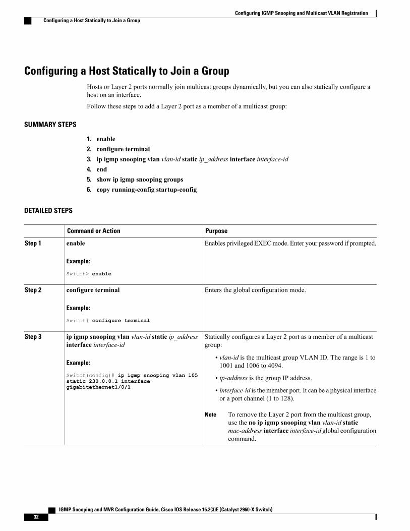
Configuring a Host Statically to Join a GroupHosts or Layer 2 ports normally join multicast groups dynamically, but you can also statically configure ahost on an interface.
Follow these steps to add a Layer 2 port as a member of a multicast group:
SUMMARY STEPS
1. enable2. configure terminal3. ip igmp snooping vlan vlan-id static ip_address interface interface-id4. end5. show ip igmp snooping groups6. copy running-config startup-config
DETAILED STEPS
PurposeCommand or Action
Enables privileged EXECmode. Enter your password if prompted.enableStep 1
Example:
Switch> enable
Enters the global configuration mode.configure terminal
Example:
Switch# configure terminal
Step 2
Statically configures a Layer 2 port as a member of a multicastgroup:
ip igmp snooping vlan vlan-id static ip_addressinterface interface-id
Step 3
Example:
Switch(config)# ip igmp snooping vlan 105
• vlan-id is the multicast group VLAN ID. The range is 1 to1001 and 1006 to 4094.
• ip-address is the group IP address.static 230.0.0.1 interfacegigabitethernet1/0/1 • interface-id is the member port. It can be a physical interface
or a port channel (1 to 128).
To remove the Layer 2 port from the multicast group,use the no ip igmp snooping vlan vlan-id staticmac-address interface interface-id global configurationcommand.
Note
IGMP Snooping and MVR Configuration Guide, Cisco IOS Release 15.2(3)E (Catalyst 2960-X Switch)32
Configuring IGMP Snooping and Multicast VLAN RegistrationConfiguring a Host Statically to Join a Group
PurposeCommand or Action
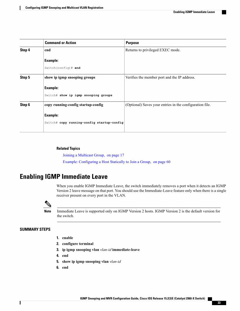
Returns to privileged EXEC mode.end
Example:
Switch(config)# end
Step 4
Verifies the member port and the IP address.show ip igmp snooping groups
Example:
Switch# show ip igmp snooping groups
Step 5
(Optional) Saves your entries in the configuration file.copy running-config startup-config
Example:
Switch# copy running-config startup-config
Step 6
Related Topics
Joining a Multicast Group, on page 17
Example: Configuring a Host Statically to Join a Group, on page 60
Enabling IGMP Immediate LeaveWhen you enable IGMP Immediate Leave, the switch immediately removes a port when it detects an IGMPVersion 2 leave message on that port. You should use the Immediate-Leave feature only when there is a singlereceiver present on every port in the VLAN.
Immediate Leave is supported only on IGMP Version 2 hosts. IGMP Version 2 is the default version forthe switch.
Note
SUMMARY STEPS
1. enable2. configure terminal3. ip igmp snooping vlan vlan-id immediate-leave4. end5. show ip igmp snooping vlan vlan-id6. end
IGMP Snooping and MVR Configuration Guide, Cisco IOS Release 15.2(3)E (Catalyst 2960-X Switch) 33
Configuring IGMP Snooping and Multicast VLAN RegistrationEnabling IGMP Immediate Leave
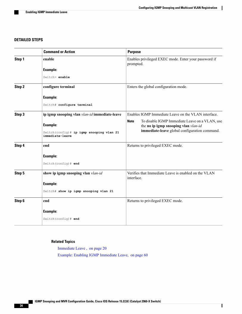
DETAILED STEPS
PurposeCommand or Action
Enables privileged EXEC mode. Enter your password ifprompted.
enable
Example:
Switch> enable
Step 1
Enters the global configuration mode.configure terminal
Example:
Switch# configure terminal
Step 2
Enables IGMP Immediate Leave on the VLAN interface.ip igmp snooping vlan vlan-id immediate-leaveStep 3
Example:
Switch(config)# ip igmp snooping vlan 21
To disable IGMP Immediate Leave on a VLAN, usethe no ip igmp snooping vlan vlan-idimmediate-leave global configuration command.
Note
immediate-leave
Returns to privileged EXEC mode.end
Example:
Switch(config)# end
Step 4
Verifies that Immediate Leave is enabled on the VLANinterface.
show ip igmp snooping vlan vlan-id
Example:
Switch# show ip igmp snooping vlan 21
Step 5
Returns to privileged EXEC mode.end
Example:
Switch(config)# end
Step 6
Related Topics
Immediate Leave , on page 20
Example: Enabling IGMP Immediate Leave, on page 60
IGMP Snooping and MVR Configuration Guide, Cisco IOS Release 15.2(3)E (Catalyst 2960-X Switch)34
Configuring IGMP Snooping and Multicast VLAN RegistrationEnabling IGMP Immediate Leave
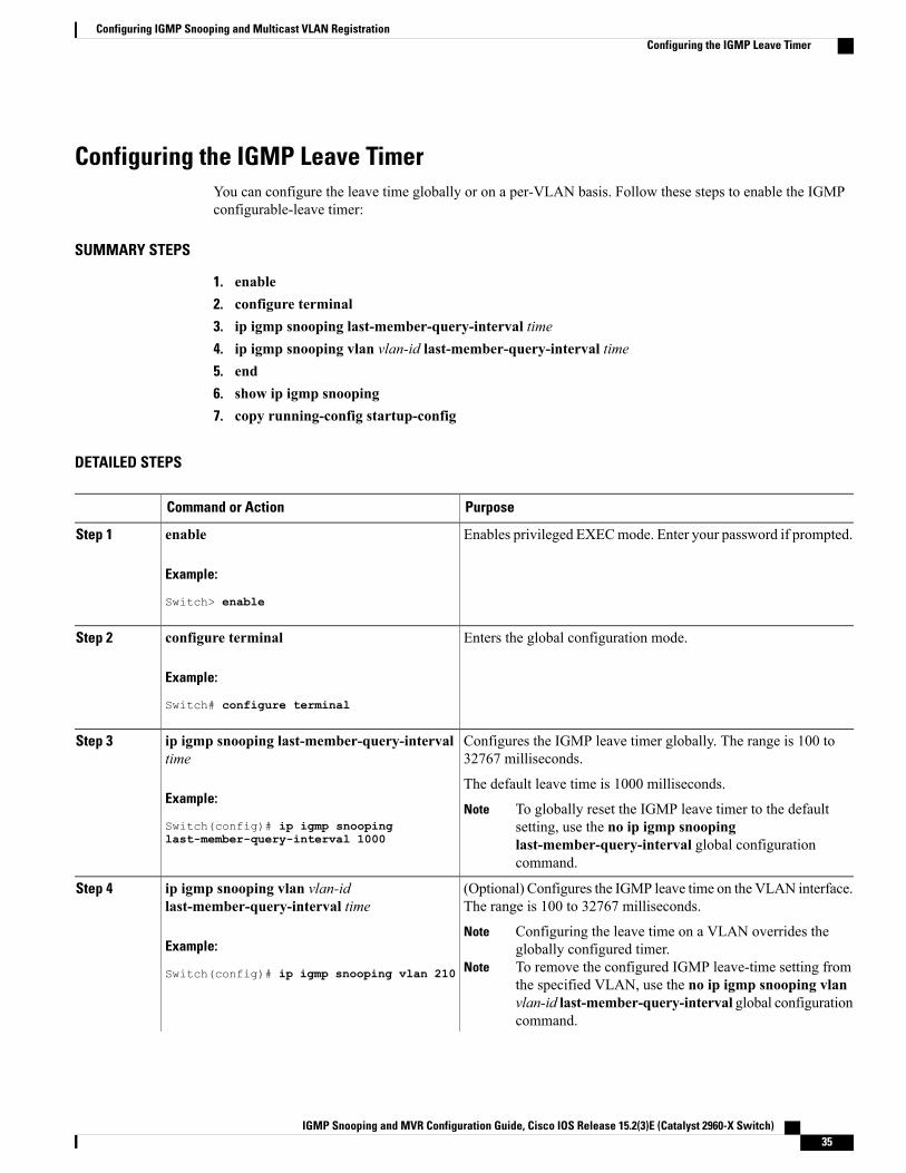
Configuring the IGMP Leave TimerYou can configure the leave time globally or on a per-VLAN basis. Follow these steps to enable the IGMPconfigurable-leave timer:
SUMMARY STEPS
1. enable2. configure terminal3. ip igmp snooping last-member-query-interval time4. ip igmp snooping vlan vlan-id last-member-query-interval time5. end6. show ip igmp snooping7. copy running-config startup-config
DETAILED STEPS
PurposeCommand or Action
Enables privileged EXECmode. Enter your password if prompted.enableStep 1
Example:
Switch> enable
Enters the global configuration mode.configure terminal
Example:
Switch# configure terminal
Step 2
Configures the IGMP leave timer globally. The range is 100 to32767 milliseconds.
ip igmp snooping last-member-query-intervaltime
Step 3
Example:
Switch(config)# ip igmp snooping
The default leave time is 1000 milliseconds.
To globally reset the IGMP leave timer to the defaultsetting, use the no ip igmp snoopinglast-member-query-interval global configurationcommand.
Note
last-member-query-interval 1000
(Optional) Configures the IGMP leave time on the VLAN interface.The range is 100 to 32767 milliseconds.
ip igmp snooping vlan vlan-idlast-member-query-interval time
Step 4
Example:
Switch(config)# ip igmp snooping vlan 210
Configuring the leave time on a VLAN overrides theglobally configured timer.
Note
To remove the configured IGMP leave-time setting fromthe specified VLAN, use the no ip igmp snooping vlanvlan-id last-member-query-interval global configurationcommand.
Note
IGMP Snooping and MVR Configuration Guide, Cisco IOS Release 15.2(3)E (Catalyst 2960-X Switch) 35
Configuring IGMP Snooping and Multicast VLAN RegistrationConfiguring the IGMP Leave Timer
PurposeCommand or Action
last-member-query-interval 1000
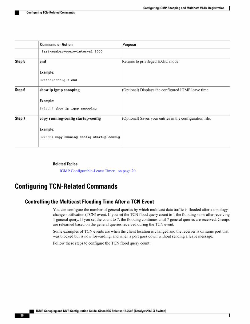
Returns to privileged EXEC mode.end
Example:
Switch(config)# end
Step 5
(Optional) Displays the configured IGMP leave time.show ip igmp snooping
Example:
Switch# show ip igmp snooping
Step 6
(Optional) Saves your entries in the configuration file.copy running-config startup-config
Example:
Switch# copy running-config startup-config
Step 7
Related Topics
IGMP Configurable-Leave Timer, on page 20
Configuring TCN-Related Commands
Controlling the Multicast Flooding Time After a TCN EventYou can configure the number of general queries by which multicast data traffic is flooded after a topologychange notification (TCN) event. If you set the TCN flood query count to 1 the flooding stops after receiving1 general query. If you set the count to 7, the flooding continues until 7 general queries are received. Groupsare relearned based on the general queries received during the TCN event.
Some examples of TCN events are when the client location is changed and the receiver is on same port thatwas blocked but is now forwarding, and when a port goes down without sending a leave message.
Follow these steps to configure the TCN flood query count:
IGMP Snooping and MVR Configuration Guide, Cisco IOS Release 15.2(3)E (Catalyst 2960-X Switch)36
Configuring IGMP Snooping and Multicast VLAN RegistrationConfiguring TCN-Related Commands
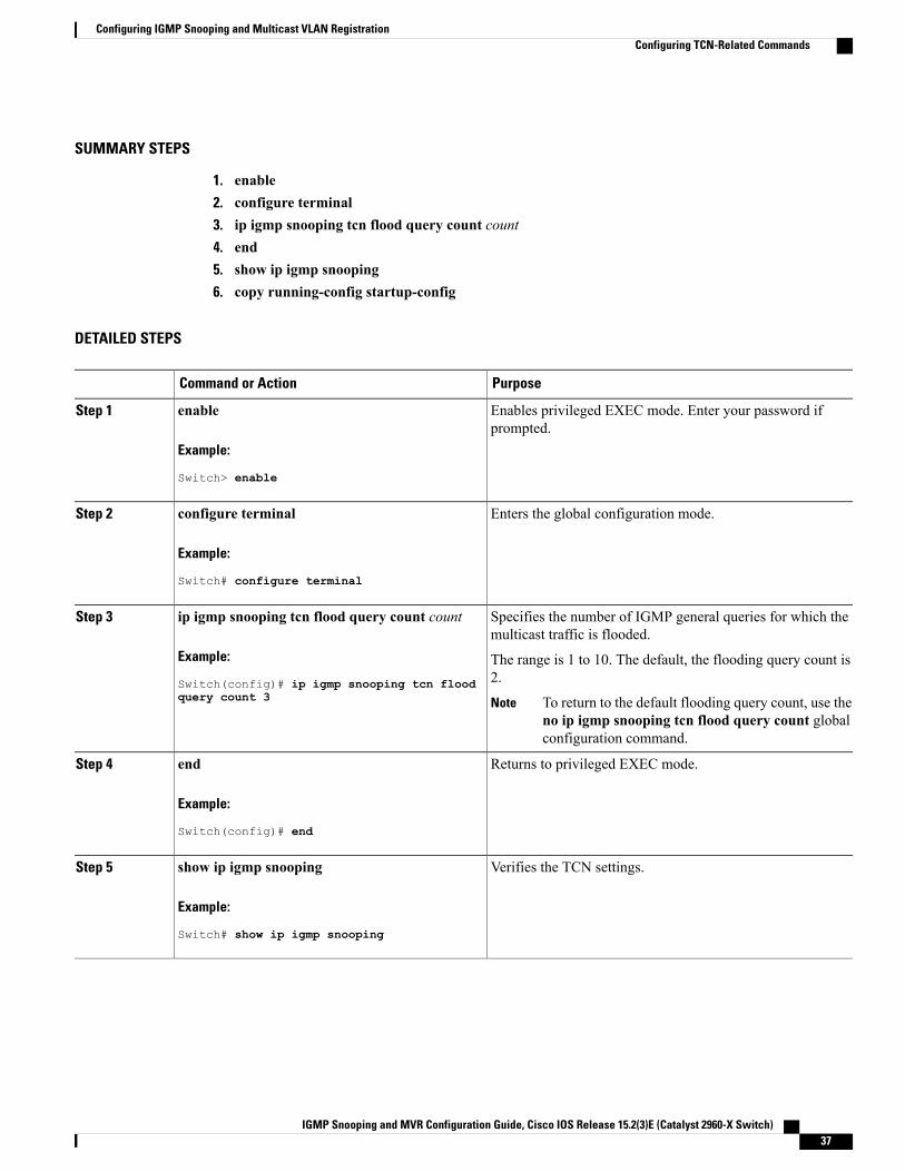
SUMMARY STEPS
1. enable2. configure terminal3. ip igmp snooping tcn flood query count count4. end5. show ip igmp snooping6. copy running-config startup-config
DETAILED STEPS
PurposeCommand or Action
Enables privileged EXEC mode. Enter your password ifprompted.
enable
Example:
Switch> enable
Step 1
Enters the global configuration mode.configure terminal
Example:
Switch# configure terminal
Step 2
Specifies the number of IGMP general queries for which themulticast traffic is flooded.
ip igmp snooping tcn flood query count count
Example:
Switch(config)# ip igmp snooping tcn flood
Step 3
The range is 1 to 10. The default, the flooding query count is2.
query count 3 To return to the default flooding query count, use theno ip igmp snooping tcn flood query count globalconfiguration command.
Note
Returns to privileged EXEC mode.end
Example:
Switch(config)# end
Step 4
Verifies the TCN settings.show ip igmp snooping
Example:
Switch# show ip igmp snooping
Step 5
IGMP Snooping and MVR Configuration Guide, Cisco IOS Release 15.2(3)E (Catalyst 2960-X Switch) 37
Configuring IGMP Snooping and Multicast VLAN RegistrationConfiguring TCN-Related Commands
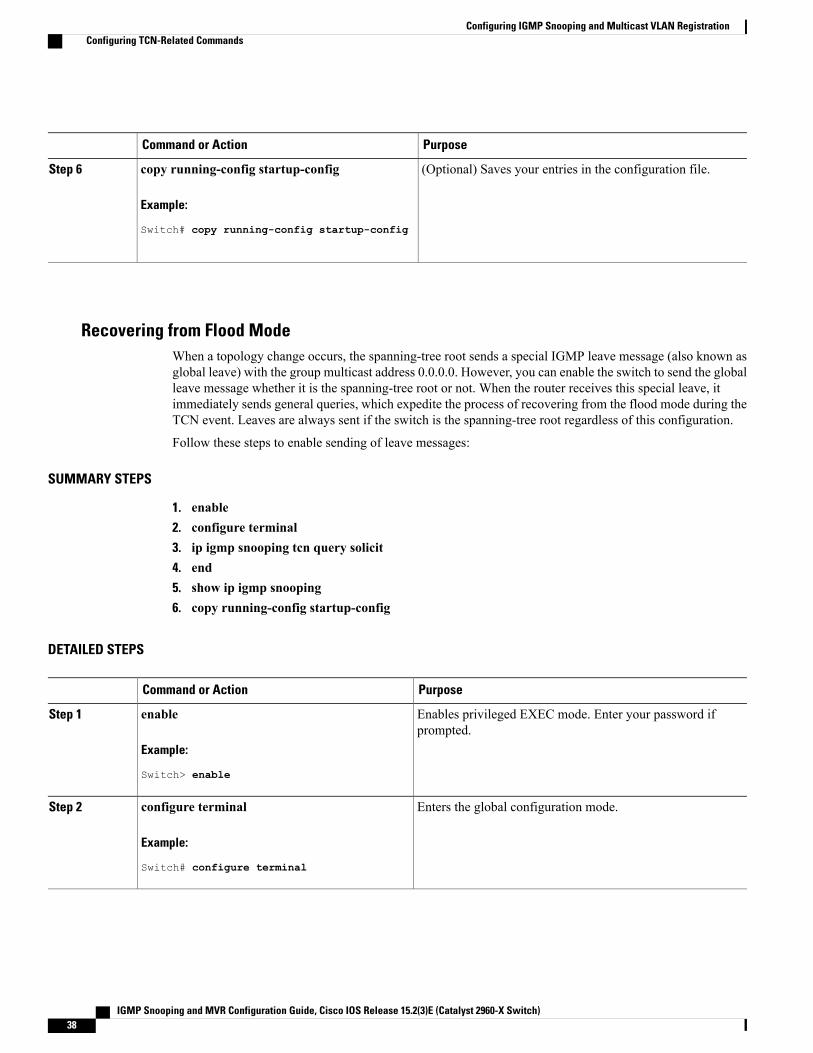
PurposeCommand or Action
(Optional) Saves your entries in the configuration file.copy running-config startup-config
Example:
Switch# copy running-config startup-config
Step 6
Recovering from Flood ModeWhen a topology change occurs, the spanning-tree root sends a special IGMP leave message (also known asglobal leave) with the group multicast address 0.0.0.0. However, you can enable the switch to send the globalleave message whether it is the spanning-tree root or not. When the router receives this special leave, itimmediately sends general queries, which expedite the process of recovering from the flood mode during theTCN event. Leaves are always sent if the switch is the spanning-tree root regardless of this configuration.
Follow these steps to enable sending of leave messages:
SUMMARY STEPS
1. enable2. configure terminal3. ip igmp snooping tcn query solicit4. end5. show ip igmp snooping6. copy running-config startup-config
DETAILED STEPS
PurposeCommand or Action
Enables privileged EXEC mode. Enter your password ifprompted.
enable
Example:
Switch> enable
Step 1
Enters the global configuration mode.configure terminal
Example:
Switch# configure terminal
Step 2
IGMP Snooping and MVR Configuration Guide, Cisco IOS Release 15.2(3)E (Catalyst 2960-X Switch)38
Configuring IGMP Snooping and Multicast VLAN RegistrationConfiguring TCN-Related Commands
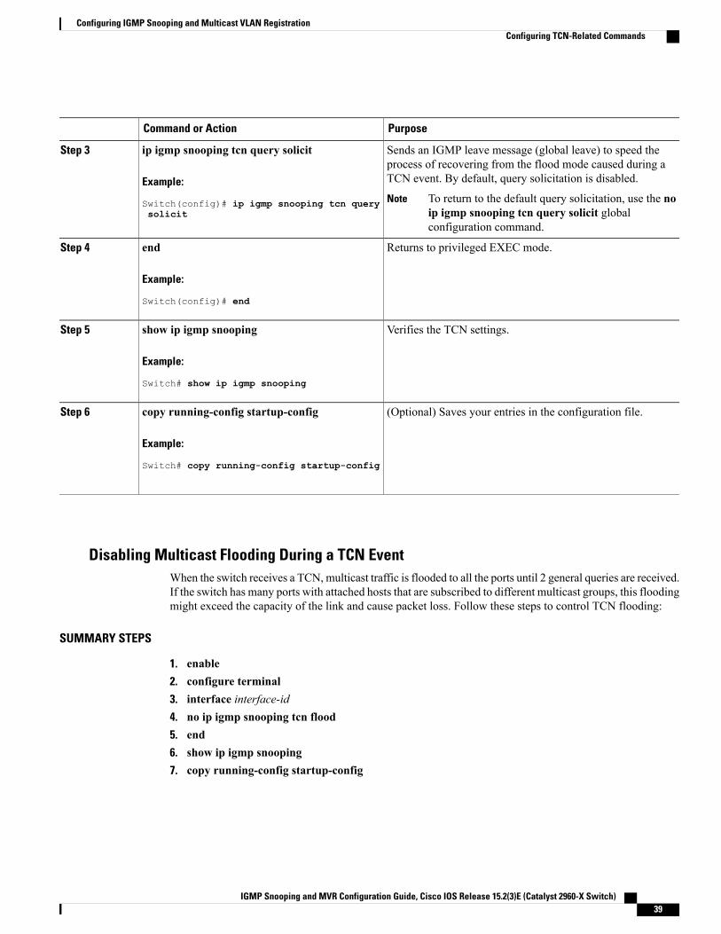
PurposeCommand or Action
Sends an IGMP leave message (global leave) to speed theprocess of recovering from the flood mode caused during aTCN event. By default, query solicitation is disabled.
ip igmp snooping tcn query solicit
Example:
Switch(config)# ip igmp snooping tcn query
Step 3
To return to the default query solicitation, use the noip igmp snooping tcn query solicit globalconfiguration command.
Notesolicit
Returns to privileged EXEC mode.end
Example:
Switch(config)# end
Step 4
Verifies the TCN settings.show ip igmp snooping
Example:
Switch# show ip igmp snooping
Step 5
(Optional) Saves your entries in the configuration file.copy running-config startup-config
Example:
Switch# copy running-config startup-config
Step 6
Disabling Multicast Flooding During a TCN EventWhen the switch receives a TCN, multicast traffic is flooded to all the ports until 2 general queries are received.If the switch has many ports with attached hosts that are subscribed to different multicast groups, this floodingmight exceed the capacity of the link and cause packet loss. Follow these steps to control TCN flooding:
SUMMARY STEPS
1. enable2. configure terminal3. interface interface-id4. no ip igmp snooping tcn flood5. end6. show ip igmp snooping7. copy running-config startup-config
IGMP Snooping and MVR Configuration Guide, Cisco IOS Release 15.2(3)E (Catalyst 2960-X Switch) 39
Configuring IGMP Snooping and Multicast VLAN RegistrationConfiguring TCN-Related Commands
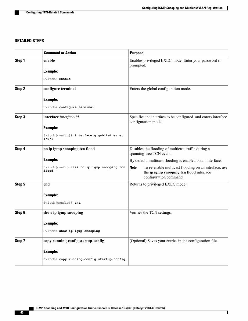
DETAILED STEPS
PurposeCommand or Action
Enables privileged EXEC mode. Enter your password ifprompted.
enable
Example:
Switch> enable
Step 1
Enters the global configuration mode.configure terminal
Example:
Switch# configure terminal
Step 2
Specifies the interface to be configured, and enters interfaceconfiguration mode.
interface interface-id
Example:
Switch(config)# interface gigabitethernet
Step 3
1/0/1
Disables the flooding of multicast traffic during aspanning-tree TCN event.
no ip igmp snooping tcn flood
Example:
Switch(config-if)# no ip igmp snooping tcn
Step 4
By default, multicast flooding is enabled on an interface.
To re-enable multicast flooding on an interface, usethe ip igmp snooping tcn flood interfaceconfiguration command.
Noteflood
Returns to privileged EXEC mode.end
Example:
Switch(config)# end
Step 5
Verifies the TCN settings.show ip igmp snooping
Example:
Switch# show ip igmp snooping
Step 6
(Optional) Saves your entries in the configuration file.copy running-config startup-config
Example:
Switch# copy running-config startup-config
Step 7
IGMP Snooping and MVR Configuration Guide, Cisco IOS Release 15.2(3)E (Catalyst 2960-X Switch)40
Configuring IGMP Snooping and Multicast VLAN RegistrationConfiguring TCN-Related Commands
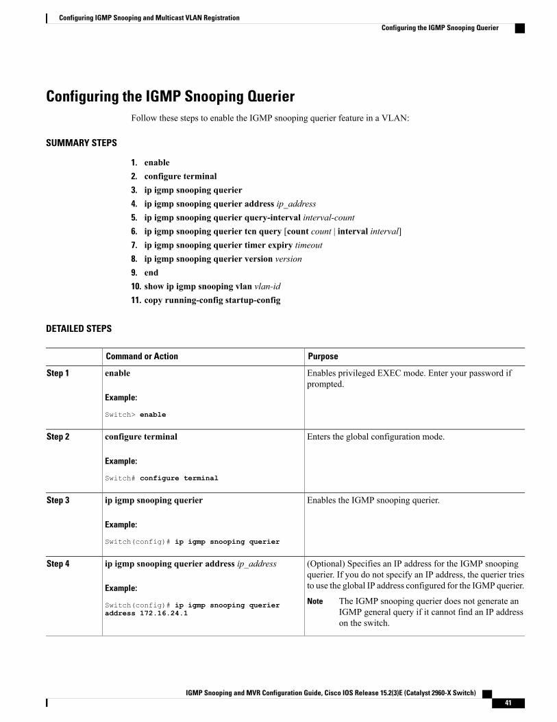
Configuring the IGMP Snooping QuerierFollow these steps to enable the IGMP snooping querier feature in a VLAN:
SUMMARY STEPS
1. enable2. configure terminal3. ip igmp snooping querier4. ip igmp snooping querier address ip_address5. ip igmp snooping querier query-interval interval-count6. ip igmp snooping querier tcn query [count count | interval interval]7. ip igmp snooping querier timer expiry timeout8. ip igmp snooping querier version version9. end10. show ip igmp snooping vlan vlan-id11. copy running-config startup-config
DETAILED STEPS
PurposeCommand or Action
Enables privileged EXEC mode. Enter your password ifprompted.
enable
Example:
Switch> enable
Step 1
Enters the global configuration mode.configure terminal
Example:
Switch# configure terminal
Step 2
Enables the IGMP snooping querier.ip igmp snooping querier
Example:
Switch(config)# ip igmp snooping querier
Step 3
(Optional) Specifies an IP address for the IGMP snoopingquerier. If you do not specify an IP address, the querier triesto use the global IP address configured for the IGMP querier.
ip igmp snooping querier address ip_address
Example:
Switch(config)# ip igmp snooping querier
Step 4
The IGMP snooping querier does not generate anIGMP general query if it cannot find an IP addresson the switch.
Noteaddress 172.16.24.1
IGMP Snooping and MVR Configuration Guide, Cisco IOS Release 15.2(3)E (Catalyst 2960-X Switch) 41
Configuring IGMP Snooping and Multicast VLAN RegistrationConfiguring the IGMP Snooping Querier
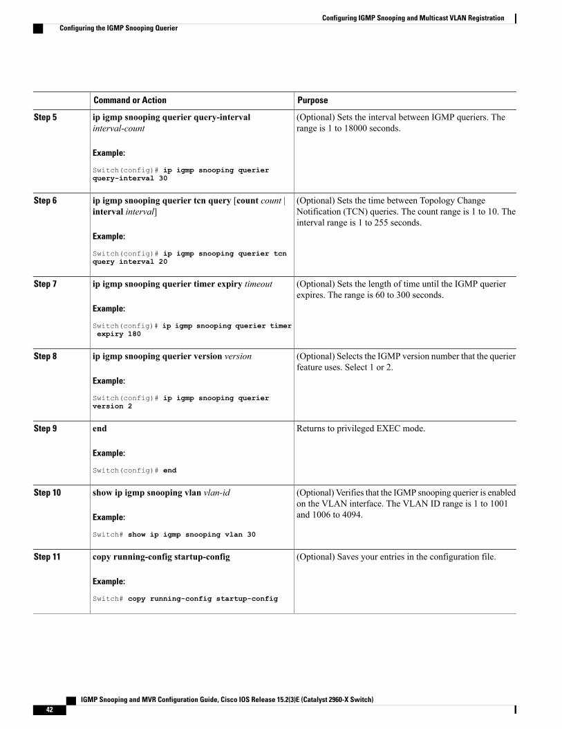
PurposeCommand or Action
(Optional) Sets the interval between IGMP queriers. Therange is 1 to 18000 seconds.
ip igmp snooping querier query-intervalinterval-count
Example:
Switch(config)# ip igmp snooping querier
Step 5
query-interval 30
(Optional) Sets the time between Topology ChangeNotification (TCN) queries. The count range is 1 to 10. Theinterval range is 1 to 255 seconds.
ip igmp snooping querier tcn query [count count |interval interval]
Example:
Switch(config)# ip igmp snooping querier tcn
Step 6
query interval 20
(Optional) Sets the length of time until the IGMP querierexpires. The range is 60 to 300 seconds.
ip igmp snooping querier timer expiry timeout
Example:
Switch(config)# ip igmp snooping querier timer
Step 7
expiry 180
(Optional) Selects the IGMP version number that the querierfeature uses. Select 1 or 2.
ip igmp snooping querier version version
Example:
Switch(config)# ip igmp snooping querier
Step 8
version 2
Returns to privileged EXEC mode.end
Example:
Switch(config)# end
Step 9
(Optional) Verifies that the IGMP snooping querier is enabledon the VLAN interface. The VLAN ID range is 1 to 1001and 1006 to 4094.
show ip igmp snooping vlan vlan-id
Example:
Switch# show ip igmp snooping vlan 30
Step 10
(Optional) Saves your entries in the configuration file.copy running-config startup-config
Example:
Switch# copy running-config startup-config
Step 11
IGMP Snooping and MVR Configuration Guide, Cisco IOS Release 15.2(3)E (Catalyst 2960-X Switch)42
Configuring IGMP Snooping and Multicast VLAN RegistrationConfiguring the IGMP Snooping Querier
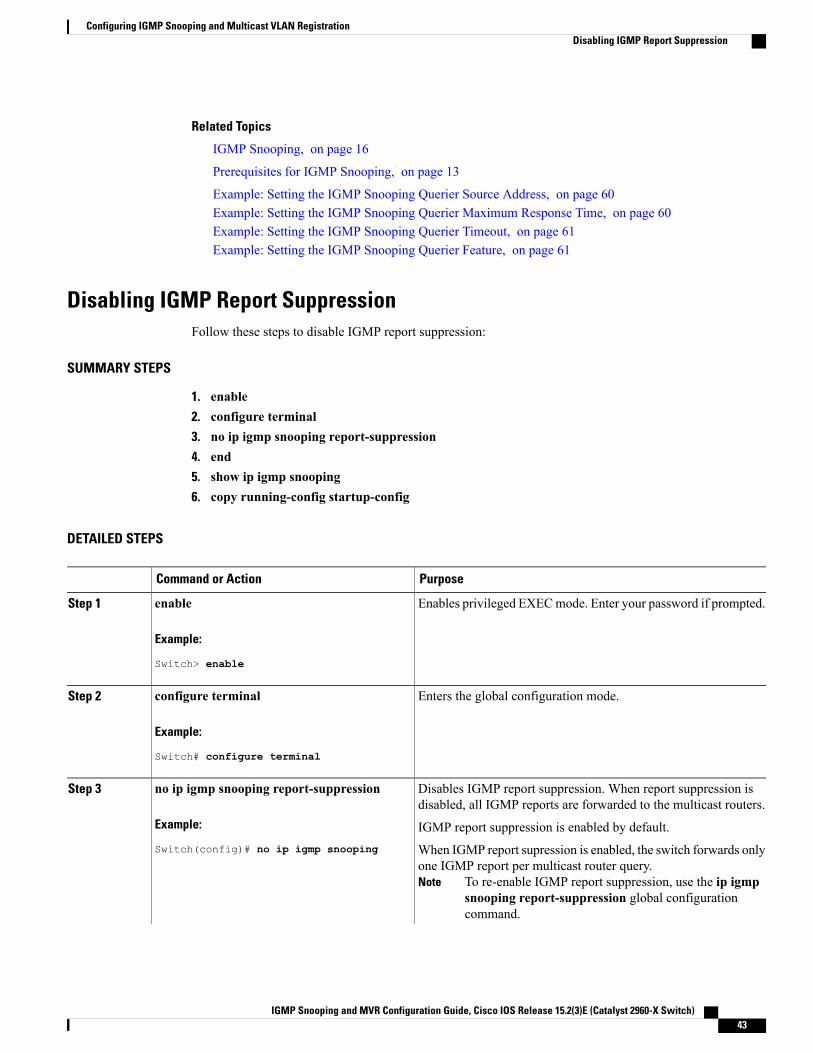
Related Topics
IGMP Snooping, on page 16
Prerequisites for IGMP Snooping, on page 13
Example: Setting the IGMP Snooping Querier Source Address, on page 60Example: Setting the IGMP Snooping Querier Maximum Response Time, on page 60Example: Setting the IGMP Snooping Querier Timeout, on page 61Example: Setting the IGMP Snooping Querier Feature, on page 61
Disabling IGMP Report SuppressionFollow these steps to disable IGMP report suppression:
SUMMARY STEPS
1. enable2. configure terminal3. no ip igmp snooping report-suppression4. end5. show ip igmp snooping6. copy running-config startup-config
DETAILED STEPS
PurposeCommand or Action
Enables privileged EXECmode. Enter your password if prompted.enableStep 1
Example:
Switch> enable
Enters the global configuration mode.configure terminal
Example:
Switch# configure terminal
Step 2
Disables IGMP report suppression. When report suppression isdisabled, all IGMP reports are forwarded to the multicast routers.
no ip igmp snooping report-suppression
Example:
Switch(config)# no ip igmp snooping
Step 3
IGMP report suppression is enabled by default.
When IGMP report supression is enabled, the switch forwards onlyone IGMP report per multicast router query.
To re-enable IGMP report suppression, use the ip igmpsnooping report-suppression global configurationcommand.
Note
IGMP Snooping and MVR Configuration Guide, Cisco IOS Release 15.2(3)E (Catalyst 2960-X Switch) 43
Configuring IGMP Snooping and Multicast VLAN RegistrationDisabling IGMP Report Suppression
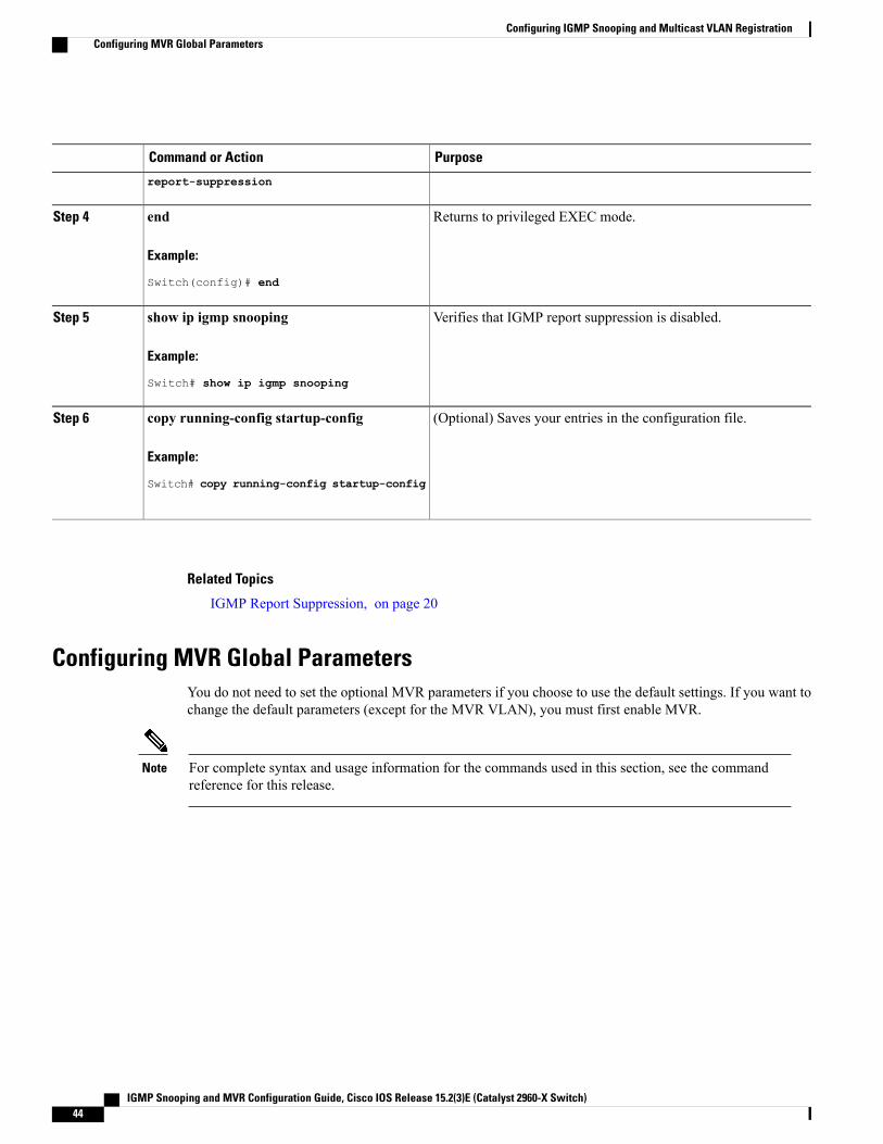
PurposeCommand or Action
report-suppression
Returns to privileged EXEC mode.end
Example:
Switch(config)# end
Step 4
Verifies that IGMP report suppression is disabled.show ip igmp snooping
Example:
Switch# show ip igmp snooping
Step 5
(Optional) Saves your entries in the configuration file.copy running-config startup-config
Example:
Switch# copy running-config startup-config
Step 6
Related Topics
IGMP Report Suppression, on page 20
Configuring MVR Global ParametersYou do not need to set the optional MVR parameters if you choose to use the default settings. If you want tochange the default parameters (except for the MVR VLAN), you must first enable MVR.
For complete syntax and usage information for the commands used in this section, see the commandreference for this release.
Note
IGMP Snooping and MVR Configuration Guide, Cisco IOS Release 15.2(3)E (Catalyst 2960-X Switch)44
Configuring IGMP Snooping and Multicast VLAN RegistrationConfiguring MVR Global Parameters
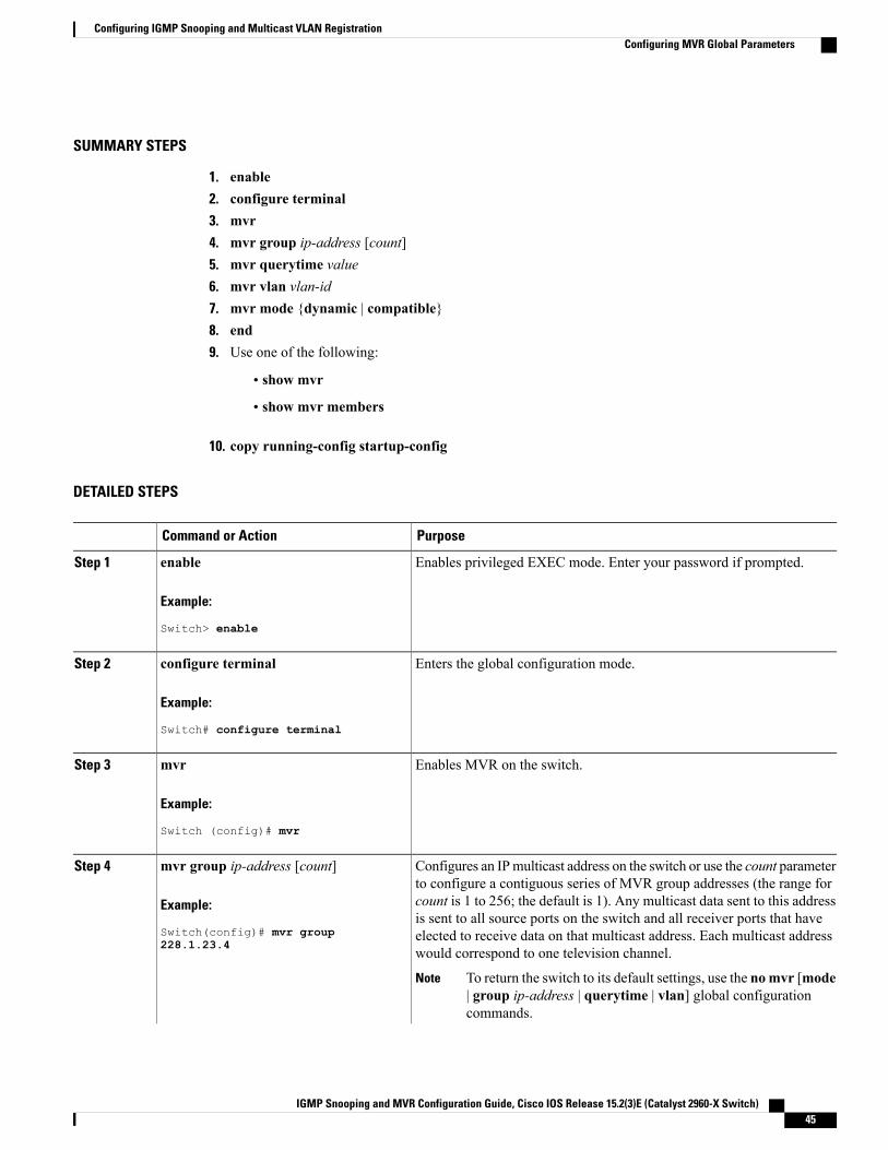
SUMMARY STEPS
1. enable2. configure terminal3. mvr4. mvr group ip-address [count]5. mvr querytime value6. mvr vlan vlan-id7. mvr mode {dynamic | compatible}8. end9. Use one of the following:
• show mvr
• show mvr members
10. copy running-config startup-config
DETAILED STEPS
PurposeCommand or Action
Enables privileged EXEC mode. Enter your password if prompted.enableStep 1
Example:
Switch> enable
Enters the global configuration mode.configure terminal
Example:
Switch# configure terminal
Step 2
Enables MVR on the switch.mvr
Example:
Switch (config)# mvr
Step 3
Configures an IPmulticast address on the switch or use the count parameterto configure a contiguous series of MVR group addresses (the range for
mvr group ip-address [count]
Example:
Switch(config)# mvr group
Step 4
count is 1 to 256; the default is 1). Any multicast data sent to this addressis sent to all source ports on the switch and all receiver ports that haveelected to receive data on that multicast address. Each multicast addresswould correspond to one television channel.228.1.23.4
To return the switch to its default settings, use the nomvr [mode| group ip-address | querytime | vlan] global configurationcommands.
Note
IGMP Snooping and MVR Configuration Guide, Cisco IOS Release 15.2(3)E (Catalyst 2960-X Switch) 45
Configuring IGMP Snooping and Multicast VLAN RegistrationConfiguring MVR Global Parameters
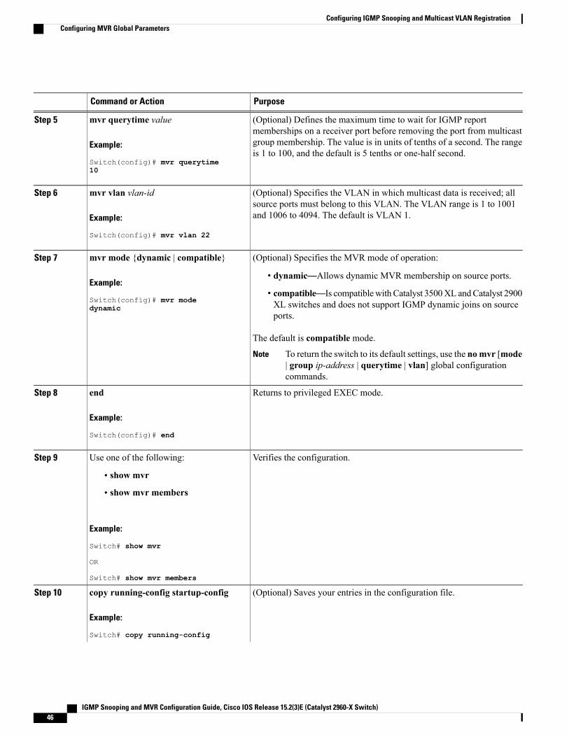
PurposeCommand or Action
(Optional) Defines the maximum time to wait for IGMP reportmemberships on a receiver port before removing the port from multicast
mvr querytime value
Example:
Switch(config)# mvr querytime
Step 5
group membership. The value is in units of tenths of a second. The rangeis 1 to 100, and the default is 5 tenths or one-half second.
10
(Optional) Specifies the VLAN in which multicast data is received; allsource ports must belong to this VLAN. The VLAN range is 1 to 1001and 1006 to 4094. The default is VLAN 1.
mvr vlan vlan-id
Example:
Switch(config)# mvr vlan 22
Step 6
(Optional) Specifies the MVR mode of operation:mvr mode {dynamic | compatible}Step 7
Example:
Switch(config)# mvr mode
• dynamic—Allows dynamic MVR membership on source ports.
• compatible—Is compatiblewith Catalyst 3500XL andCatalyst 2900XL switches and does not support IGMP dynamic joins on sourceports.
dynamic
The default is compatible mode.
To return the switch to its default settings, use the nomvr [mode| group ip-address | querytime | vlan] global configurationcommands.
Note
Returns to privileged EXEC mode.end
Example:
Switch(config)# end
Step 8
Verifies the configuration.Use one of the following:Step 9
• show mvr
• show mvr members
Example:
Switch# show mvr
OR
Switch# show mvr members
(Optional) Saves your entries in the configuration file.copy running-config startup-config
Example:
Switch# copy running-config
Step 10
IGMP Snooping and MVR Configuration Guide, Cisco IOS Release 15.2(3)E (Catalyst 2960-X Switch)46
Configuring IGMP Snooping and Multicast VLAN RegistrationConfiguring MVR Global Parameters
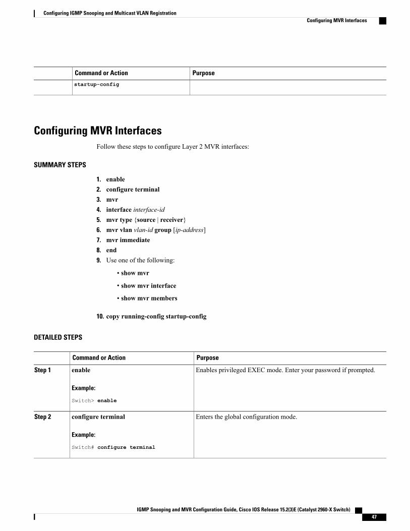
PurposeCommand or Action
startup-config
Configuring MVR InterfacesFollow these steps to configure Layer 2 MVR interfaces:
SUMMARY STEPS
1. enable2. configure terminal3. mvr4. interface interface-id5. mvr type {source | receiver}6. mvr vlan vlan-id group [ip-address]7. mvr immediate8. end9. Use one of the following:
• show mvr
• show mvr interface
• show mvr members
10. copy running-config startup-config
DETAILED STEPS
PurposeCommand or Action
Enables privileged EXEC mode. Enter your password if prompted.enableStep 1
Example:
Switch> enable
Enters the global configuration mode.configure terminal
Example:
Switch# configure terminal
Step 2
IGMP Snooping and MVR Configuration Guide, Cisco IOS Release 15.2(3)E (Catalyst 2960-X Switch) 47
Configuring IGMP Snooping and Multicast VLAN RegistrationConfiguring MVR Interfaces
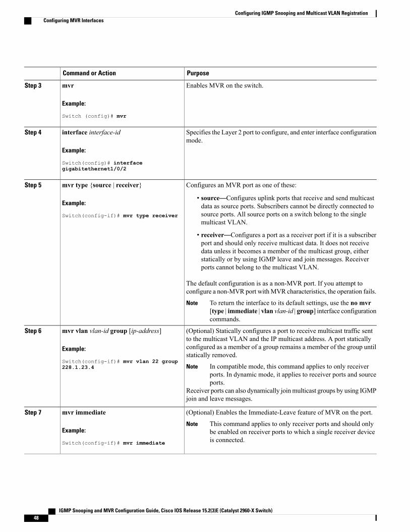
PurposeCommand or Action
Enables MVR on the switch.mvr
Example:
Switch (config)# mvr
Step 3
Specifies the Layer 2 port to configure, and enter interface configurationmode.
interface interface-id
Example:
Switch(config)# interface
Step 4
gigabitethernet1/0/2
Configures an MVR port as one of these:mvr type {source | receiver}Step 5
Example:
Switch(config-if)# mvr type receiver
• source—Configures uplink ports that receive and send multicastdata as source ports. Subscribers cannot be directly connected tosource ports. All source ports on a switch belong to the singlemulticast VLAN.
• receiver—Configures a port as a receiver port if it is a subscriberport and should only receive multicast data. It does not receivedata unless it becomes a member of the multicast group, eitherstatically or by using IGMP leave and join messages. Receiverports cannot belong to the multicast VLAN.
The default configuration is as a non-MVR port. If you attempt toconfigure a non-MVR port withMVR characteristics, the operation fails.
To return the interface to its default settings, use the no mvr[type | immediate | vlan vlan-id | group] interface configurationcommands.
Note
(Optional) Statically configures a port to receive multicast traffic sentto the multicast VLAN and the IP multicast address. A port statically
mvr vlan vlan-id group [ip-address]
Example:
Switch(config-if)# mvr vlan 22 group
Step 6
configured as a member of a group remains a member of the group untilstatically removed.
In compatible mode, this command applies to only receiverports. In dynamic mode, it applies to receiver ports and sourceports.
Note
Receiver ports can also dynamically joinmulticast groups by using IGMPjoin and leave messages.
228.1.23.4
(Optional) Enables the Immediate-Leave feature of MVR on the port.mvr immediateStep 7
Example:
Switch(config-if)# mvr immediate
This command applies to only receiver ports and should onlybe enabled on receiver ports to which a single receiver deviceis connected.
Note
IGMP Snooping and MVR Configuration Guide, Cisco IOS Release 15.2(3)E (Catalyst 2960-X Switch)48
Configuring IGMP Snooping and Multicast VLAN RegistrationConfiguring MVR Interfaces
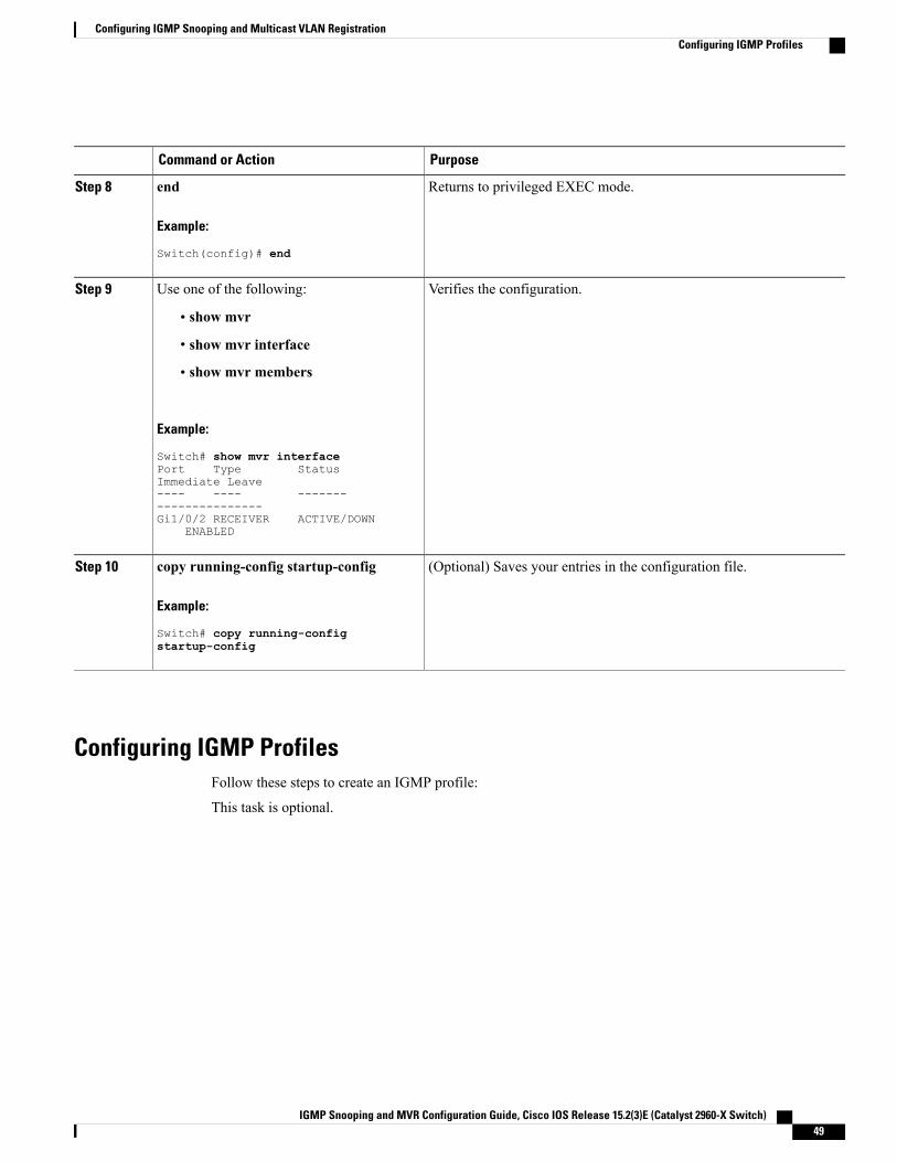
PurposeCommand or Action
Returns to privileged EXEC mode.end
Example:
Switch(config)# end
Step 8
Verifies the configuration.Use one of the following:Step 9
• show mvr
• show mvr interface
• show mvr members
Example:
Switch# show mvr interfacePort Type StatusImmediate Leave---- ---- ----------------------Gi1/0/2 RECEIVER ACTIVE/DOWN
ENABLED
(Optional) Saves your entries in the configuration file.copy running-config startup-config
Example:
Switch# copy running-config
Step 10
startup-config
Configuring IGMP ProfilesFollow these steps to create an IGMP profile:
This task is optional.
IGMP Snooping and MVR Configuration Guide, Cisco IOS Release 15.2(3)E (Catalyst 2960-X Switch) 49
Configuring IGMP Snooping and Multicast VLAN RegistrationConfiguring IGMP Profiles
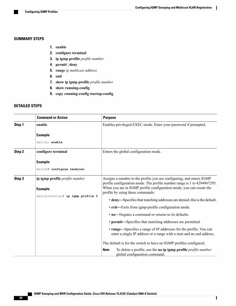
SUMMARY STEPS
1. enable2. configure terminal3. ip igmp profile profile number4. permit | deny5. range ip multicast address6. end7. show ip igmp profile profile number8. show running-config9. copy running-config startup-config
DETAILED STEPS
PurposeCommand or Action
Enables privileged EXEC mode. Enter your password if prompted.enableStep 1
Example:
Switch> enable
Enters the global configuration mode.configure terminal
Example:
Switch# configure terminal
Step 2
Assigns a number to the profile you are configuring, and enters IGMPprofile configuration mode. The profile number range is 1 to 4294967295.
ip igmp profile profile number
Example:
Switch(config)# ip igmp profile 3
Step 3
When you are in IGMP profile configuration mode, you can create theprofile by using these commands:
• deny—Specifies that matching addresses are denied; this is the default.
• exit—Exits from igmp-profile configuration mode.
• no—Negates a command or returns to its defaults.
• permit—Specifies that matching addresses are permitted.
• range—Specifies a range of IP addresses for the profile. You canenter a single IP address or a range with a start and an end address.
The default is for the switch to have no IGMP profiles configured.
To delete a profile, use the no ip igmp profile profile numberglobal configuration command.
Note
IGMP Snooping and MVR Configuration Guide, Cisco IOS Release 15.2(3)E (Catalyst 2960-X Switch)50
Configuring IGMP Snooping and Multicast VLAN RegistrationConfiguring IGMP Profiles
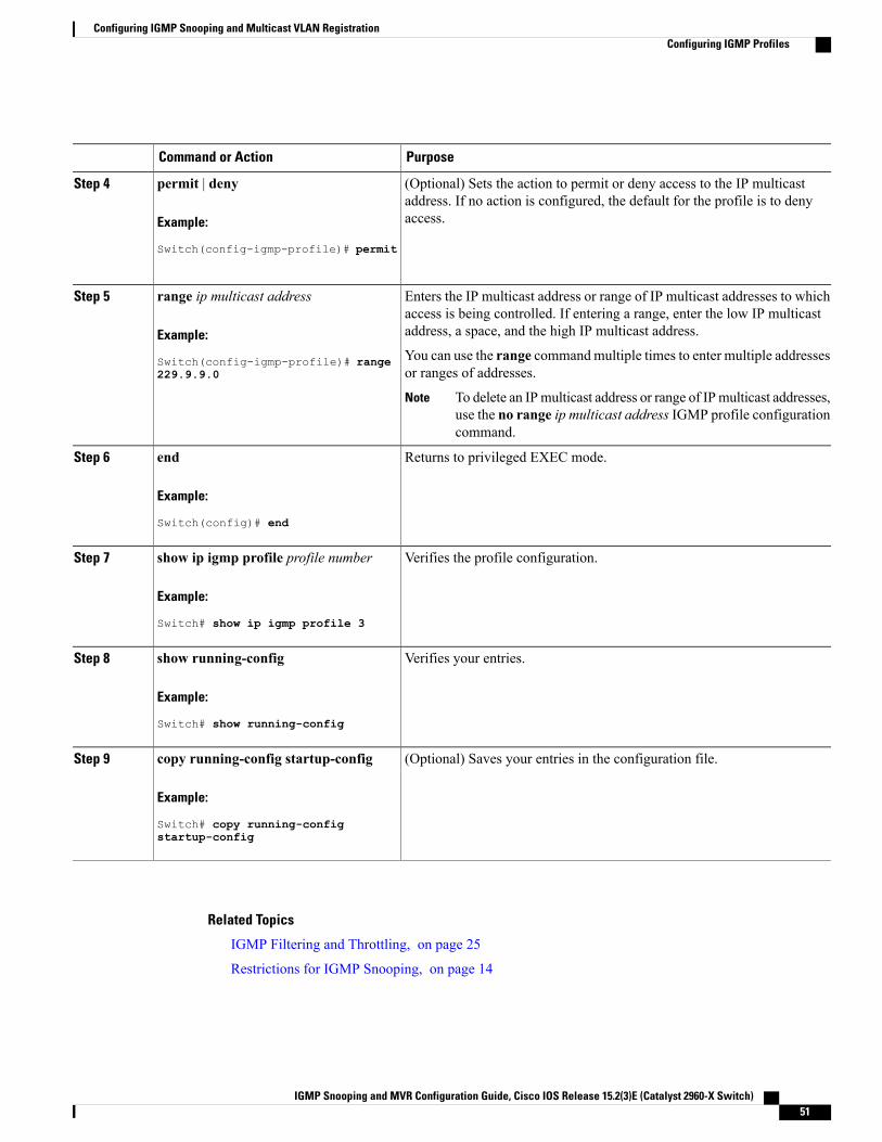
PurposeCommand or Action
(Optional) Sets the action to permit or deny access to the IP multicastaddress. If no action is configured, the default for the profile is to denyaccess.
permit | deny
Example:
Switch(config-igmp-profile)# permit
Step 4
Enters the IP multicast address or range of IP multicast addresses to whichaccess is being controlled. If entering a range, enter the low IP multicastaddress, a space, and the high IP multicast address.
range ip multicast address
Example:
Switch(config-igmp-profile)# range
Step 5
You can use the range commandmultiple times to enter multiple addressesor ranges of addresses.229.9.9.0
To delete an IPmulticast address or range of IPmulticast addresses,use the no range ip multicast address IGMP profile configurationcommand.
Note
Returns to privileged EXEC mode.end
Example:
Switch(config)# end
Step 6
Verifies the profile configuration.show ip igmp profile profile number
Example:
Switch# show ip igmp profile 3
Step 7
Verifies your entries.show running-config
Example:
Switch# show running-config
Step 8
(Optional) Saves your entries in the configuration file.copy running-config startup-config
Example:
Switch# copy running-config
Step 9
startup-config
Related Topics
IGMP Filtering and Throttling, on page 25
Restrictions for IGMP Snooping, on page 14
IGMP Snooping and MVR Configuration Guide, Cisco IOS Release 15.2(3)E (Catalyst 2960-X Switch) 51
Configuring IGMP Snooping and Multicast VLAN RegistrationConfiguring IGMP Profiles
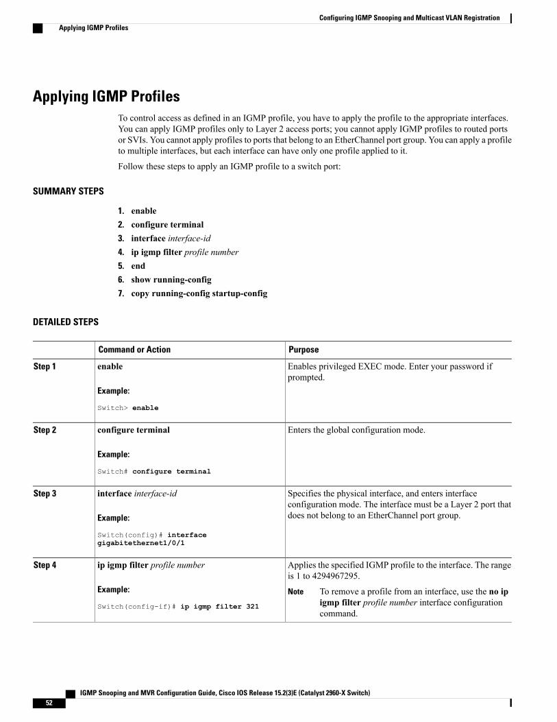
Applying IGMP ProfilesTo control access as defined in an IGMP profile, you have to apply the profile to the appropriate interfaces.You can apply IGMP profiles only to Layer 2 access ports; you cannot apply IGMP profiles to routed portsor SVIs. You cannot apply profiles to ports that belong to an EtherChannel port group. You can apply a profileto multiple interfaces, but each interface can have only one profile applied to it.
Follow these steps to apply an IGMP profile to a switch port:
SUMMARY STEPS
1. enable2. configure terminal3. interface interface-id4. ip igmp filter profile number5. end6. show running-config7. copy running-config startup-config
DETAILED STEPS
PurposeCommand or Action
Enables privileged EXEC mode. Enter your password ifprompted.
enable
Example:
Switch> enable
Step 1
Enters the global configuration mode.configure terminal
Example:
Switch# configure terminal
Step 2
Specifies the physical interface, and enters interfaceconfiguration mode. The interface must be a Layer 2 port thatdoes not belong to an EtherChannel port group.
interface interface-id
Example:
Switch(config)# interface
Step 3
gigabitethernet1/0/1
Applies the specified IGMP profile to the interface. The rangeis 1 to 4294967295.
ip igmp filter profile number
Example:
Switch(config-if)# ip igmp filter 321
Step 4
To remove a profile from an interface, use the no ipigmp filter profile number interface configurationcommand.
Note
IGMP Snooping and MVR Configuration Guide, Cisco IOS Release 15.2(3)E (Catalyst 2960-X Switch)52
Configuring IGMP Snooping and Multicast VLAN RegistrationApplying IGMP Profiles
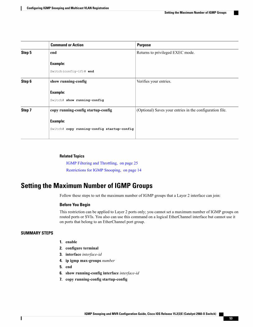
PurposeCommand or Action
Returns to privileged EXEC mode.end
Example:
Switch(config-if)# end
Step 5
Verifies your entries.show running-config
Example:
Switch# show running-config
Step 6
(Optional) Saves your entries in the configuration file.copy running-config startup-config
Example:
Switch# copy running-config startup-config
Step 7
Related Topics
IGMP Filtering and Throttling, on page 25
Restrictions for IGMP Snooping, on page 14
Setting the Maximum Number of IGMP GroupsFollow these steps to set the maximum number of IGMP groups that a Layer 2 interface can join:
Before You Begin
This restriction can be applied to Layer 2 ports only; you cannot set a maximum number of IGMP groups onrouted ports or SVIs. You also can use this command on a logical EtherChannel interface but cannot use iton ports that belong to an EtherChannel port group.
SUMMARY STEPS
1. enable2. configure terminal3. interface interface-id4. ip igmp max-groups number5. end6. show running-config interface interface-id7. copy running-config startup-config
IGMP Snooping and MVR Configuration Guide, Cisco IOS Release 15.2(3)E (Catalyst 2960-X Switch) 53
Configuring IGMP Snooping and Multicast VLAN RegistrationSetting the Maximum Number of IGMP Groups
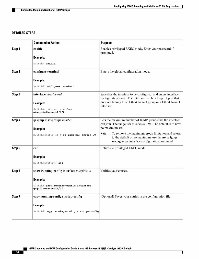
DETAILED STEPS
PurposeCommand or Action
Enables privileged EXEC mode. Enter your password ifprompted.
enable
Example:
Switch> enable
Step 1
Enters the global configuration mode.configure terminal
Example:
Switch# configure terminal
Step 2
Specifies the interface to be configured, and enters interfaceconfiguration mode. The interface can be a Layer 2 port that
interface interface-id
Example:
Switch(config)# interface
Step 3
does not belong to an EtherChannel group or a EtherChannelinterface.
gigabitethernet1/0/2
Sets the maximum number of IGMP groups that the interfacecan join. The range is 0 to 4294967294. The default is to haveno maximum set.
ip igmp max-groups number
Example:
Switch(config-if)# ip igmp max-groups 20
Step 4
To remove the maximum group limitation and returnto the default of no maximum, use the no ip igmpmax-groups interface configuration command.
Note
Returns to privileged EXEC mode.end
Example:
Switch(config)# end
Step 5
Verifies your entries.show running-config interface interface-id
Example:
Switch# show running-config interface
Step 6
gigabitethernet1/0/1
(Optional) Saves your entries in the configuration file.copy running-config startup-config
Example:
Switch# copy running-config startup-config
Step 7
IGMP Snooping and MVR Configuration Guide, Cisco IOS Release 15.2(3)E (Catalyst 2960-X Switch)54
Configuring IGMP Snooping and Multicast VLAN RegistrationSetting the Maximum Number of IGMP Groups
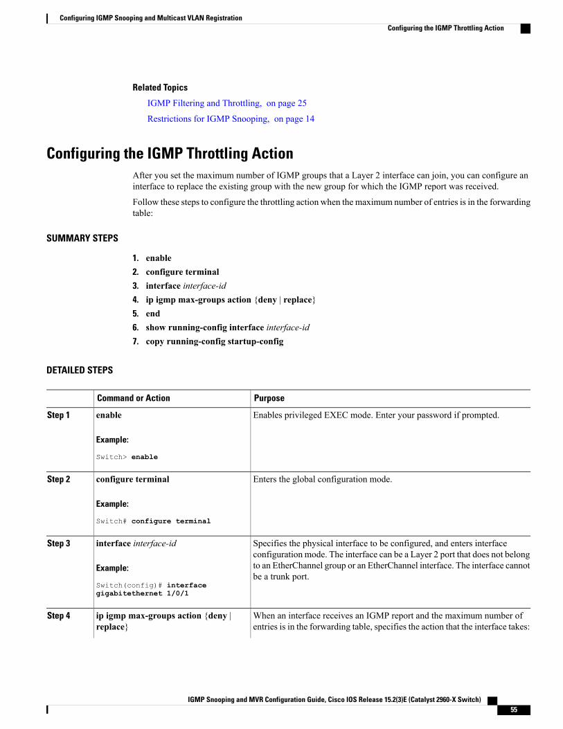
Related Topics
IGMP Filtering and Throttling, on page 25
Restrictions for IGMP Snooping, on page 14
Configuring the IGMP Throttling ActionAfter you set the maximum number of IGMP groups that a Layer 2 interface can join, you can configure aninterface to replace the existing group with the new group for which the IGMP report was received.
Follow these steps to configure the throttling action when the maximum number of entries is in the forwardingtable:
SUMMARY STEPS
1. enable2. configure terminal3. interface interface-id4. ip igmp max-groups action {deny | replace}5. end6. show running-config interface interface-id7. copy running-config startup-config
DETAILED STEPS
PurposeCommand or Action
Enables privileged EXEC mode. Enter your password if prompted.enableStep 1
Example:
Switch> enable
Enters the global configuration mode.configure terminal
Example:
Switch# configure terminal
Step 2
Specifies the physical interface to be configured, and enters interfaceconfiguration mode. The interface can be a Layer 2 port that does not belong
interface interface-id
Example:
Switch(config)# interface
Step 3
to an EtherChannel group or an EtherChannel interface. The interface cannotbe a trunk port.
gigabitethernet 1/0/1
When an interface receives an IGMP report and the maximum number ofentries is in the forwarding table, specifies the action that the interface takes:
ip igmp max-groups action {deny |replace}
Step 4
IGMP Snooping and MVR Configuration Guide, Cisco IOS Release 15.2(3)E (Catalyst 2960-X Switch) 55
Configuring IGMP Snooping and Multicast VLAN RegistrationConfiguring the IGMP Throttling Action
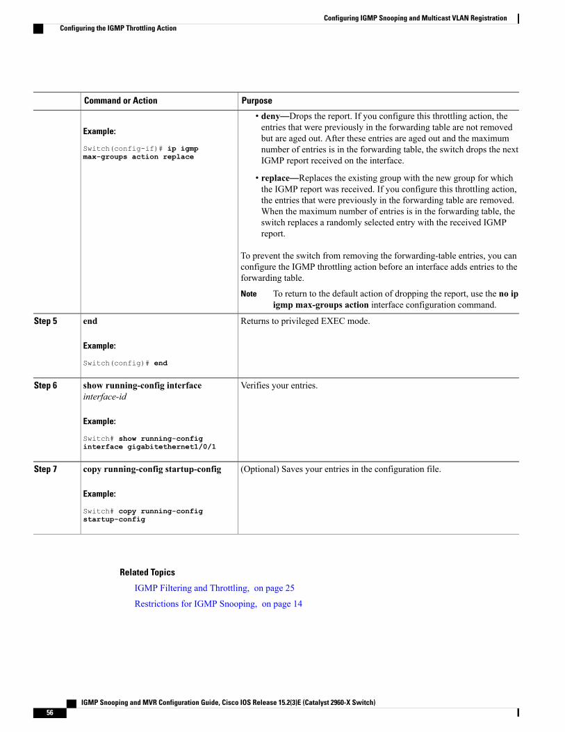
PurposeCommand or Action
Example:
Switch(config-if)# ip igmp
• deny—Drops the report. If you configure this throttling action, theentries that were previously in the forwarding table are not removedbut are aged out. After these entries are aged out and the maximumnumber of entries is in the forwarding table, the switch drops the nextIGMP report received on the interface.max-groups action replace
• replace—Replaces the existing group with the new group for whichthe IGMP report was received. If you configure this throttling action,the entries that were previously in the forwarding table are removed.When the maximum number of entries is in the forwarding table, theswitch replaces a randomly selected entry with the received IGMPreport.
To prevent the switch from removing the forwarding-table entries, you canconfigure the IGMP throttling action before an interface adds entries to theforwarding table.
To return to the default action of dropping the report, use the no ipigmp max-groups action interface configuration command.
Note
Returns to privileged EXEC mode.end
Example:
Switch(config)# end
Step 5
Verifies your entries.show running-config interfaceinterface-id
Step 6
Example:
Switch# show running-configinterface gigabitethernet1/0/1
(Optional) Saves your entries in the configuration file.copy running-config startup-config
Example:
Switch# copy running-config
Step 7
startup-config
Related Topics
IGMP Filtering and Throttling, on page 25
Restrictions for IGMP Snooping, on page 14
IGMP Snooping and MVR Configuration Guide, Cisco IOS Release 15.2(3)E (Catalyst 2960-X Switch)56
Configuring IGMP Snooping and Multicast VLAN RegistrationConfiguring the IGMP Throttling Action
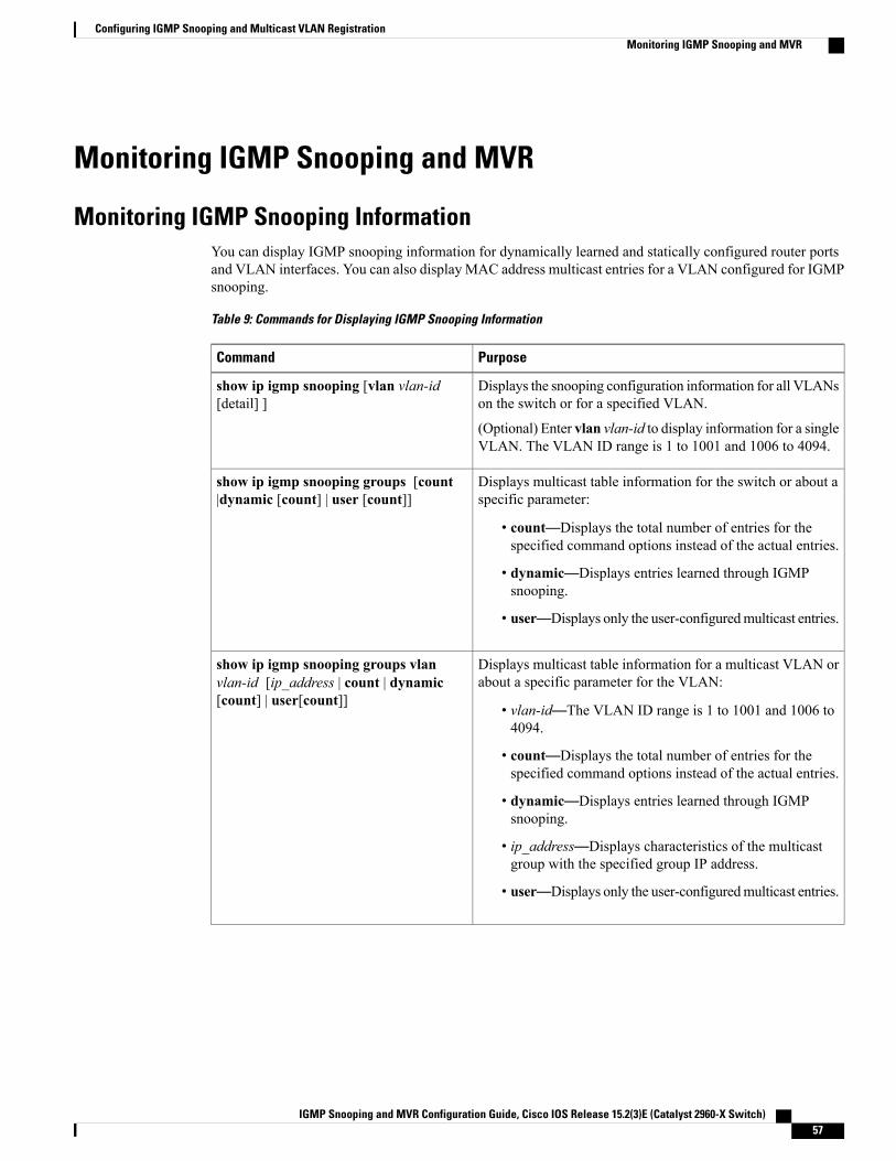
Monitoring IGMP Snooping and MVR
Monitoring IGMP Snooping InformationYou can display IGMP snooping information for dynamically learned and statically configured router portsand VLAN interfaces. You can also display MAC address multicast entries for a VLAN configured for IGMPsnooping.
Table 9: Commands for Displaying IGMP Snooping Information
PurposeCommand
Displays the snooping configuration information for all VLANson the switch or for a specified VLAN.
(Optional) Enter vlan vlan-id to display information for a singleVLAN. The VLAN ID range is 1 to 1001 and 1006 to 4094.
show ip igmp snooping [vlan vlan-id[detail] ]
Displays multicast table information for the switch or about aspecific parameter:
• count—Displays the total number of entries for thespecified command options instead of the actual entries.
• dynamic—Displays entries learned through IGMPsnooping.
• user—Displays only the user-configuredmulticast entries.
show ip igmp snooping groups [count|dynamic [count] | user [count]]
Displays multicast table information for a multicast VLAN orabout a specific parameter for the VLAN:
• vlan-id—The VLAN ID range is 1 to 1001 and 1006 to4094.
• count—Displays the total number of entries for thespecified command options instead of the actual entries.
• dynamic—Displays entries learned through IGMPsnooping.
• ip_address—Displays characteristics of the multicastgroup with the specified group IP address.
• user—Displays only the user-configuredmulticast entries.
show ip igmp snooping groups vlanvlan-id [ip_address | count | dynamic[count] | user[count]]
IGMP Snooping and MVR Configuration Guide, Cisco IOS Release 15.2(3)E (Catalyst 2960-X Switch) 57
Configuring IGMP Snooping and Multicast VLAN RegistrationMonitoring IGMP Snooping and MVR
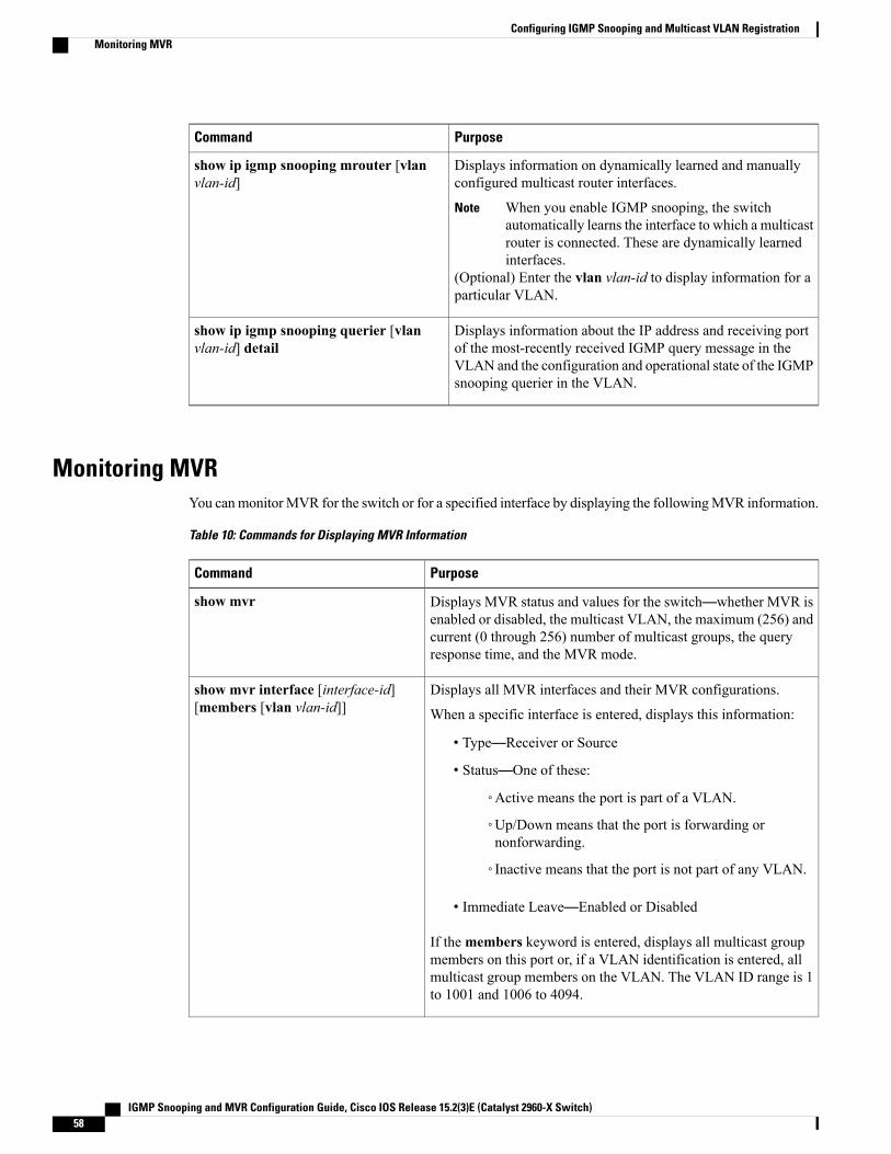
PurposeCommand
Displays information on dynamically learned and manuallyconfigured multicast router interfaces.
When you enable IGMP snooping, the switchautomatically learns the interface to which a multicastrouter is connected. These are dynamically learnedinterfaces.
Note
(Optional) Enter the vlan vlan-id to display information for aparticular VLAN.
show ip igmp snooping mrouter [vlanvlan-id]
Displays information about the IP address and receiving portof the most-recently received IGMP query message in theVLAN and the configuration and operational state of the IGMPsnooping querier in the VLAN.
show ip igmp snooping querier [vlanvlan-id] detail
Monitoring MVRYou canmonitorMVR for the switch or for a specified interface by displaying the followingMVR information.
Table 10: Commands for Displaying MVR Information
PurposeCommand
Displays MVR status and values for the switch—whether MVR isenabled or disabled, the multicast VLAN, the maximum (256) andcurrent (0 through 256) number of multicast groups, the queryresponse time, and the MVR mode.
show mvr
Displays all MVR interfaces and their MVR configurations.
When a specific interface is entered, displays this information:
• Type—Receiver or Source
• Status—One of these:
◦Active means the port is part of a VLAN.
◦Up/Down means that the port is forwarding ornonforwarding.
◦Inactive means that the port is not part of any VLAN.
• Immediate Leave—Enabled or Disabled
If themembers keyword is entered, displays all multicast groupmembers on this port or, if a VLAN identification is entered, allmulticast group members on the VLAN. The VLAN ID range is 1to 1001 and 1006 to 4094.
show mvr interface [interface-id][members [vlan vlan-id]]
IGMP Snooping and MVR Configuration Guide, Cisco IOS Release 15.2(3)E (Catalyst 2960-X Switch)58
Configuring IGMP Snooping and Multicast VLAN RegistrationMonitoring MVR
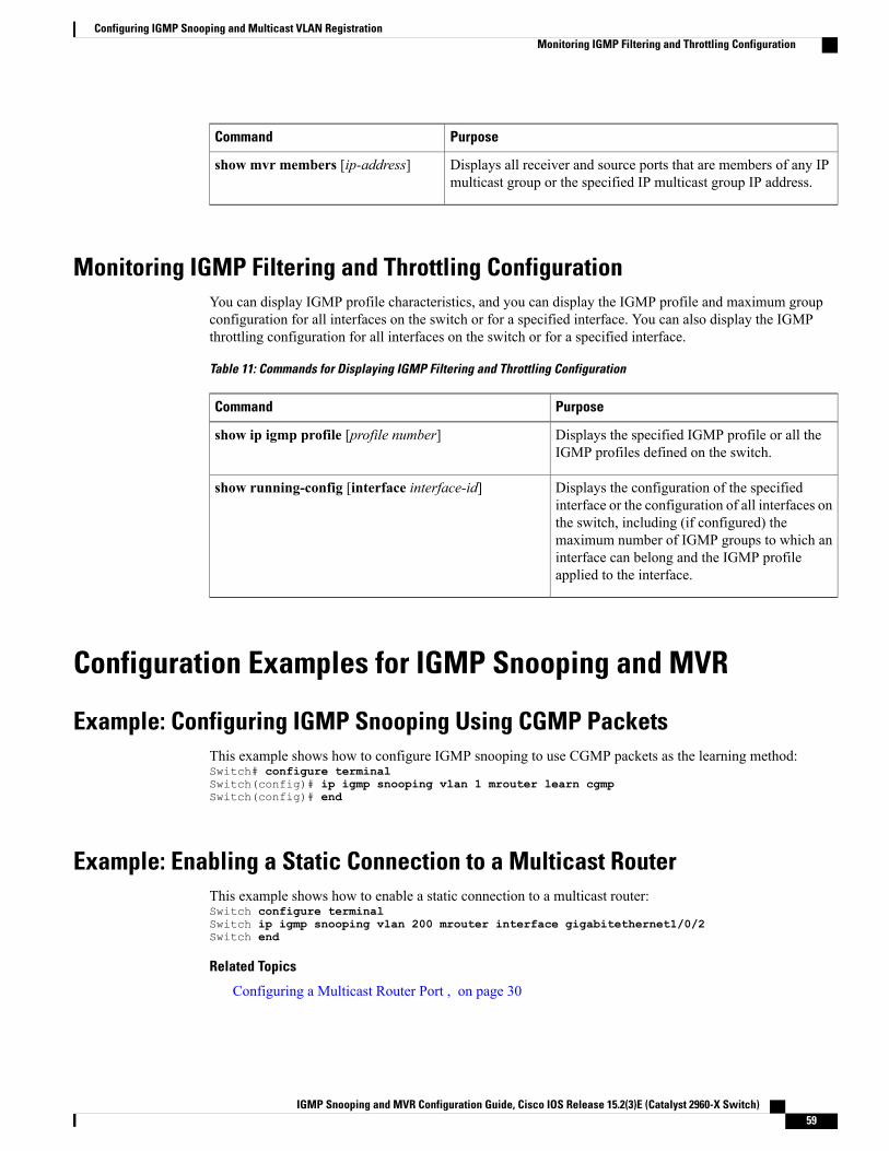
PurposeCommand
Displays all receiver and source ports that are members of any IPmulticast group or the specified IP multicast group IP address.
show mvr members [ip-address]
Monitoring IGMP Filtering and Throttling ConfigurationYou can display IGMP profile characteristics, and you can display the IGMP profile and maximum groupconfiguration for all interfaces on the switch or for a specified interface. You can also display the IGMPthrottling configuration for all interfaces on the switch or for a specified interface.
Table 11: Commands for Displaying IGMP Filtering and Throttling Configuration
PurposeCommand
Displays the specified IGMP profile or all theIGMP profiles defined on the switch.
show ip igmp profile [profile number]
Displays the configuration of the specifiedinterface or the configuration of all interfaces onthe switch, including (if configured) themaximum number of IGMP groups to which aninterface can belong and the IGMP profileapplied to the interface.
show running-config [interface interface-id]
Configuration Examples for IGMP Snooping and MVR
Example: Configuring IGMP Snooping Using CGMP PacketsThis example shows how to configure IGMP snooping to use CGMP packets as the learning method:Switch# configure terminalSwitch(config)# ip igmp snooping vlan 1 mrouter learn cgmpSwitch(config)# end
Example: Enabling a Static Connection to a Multicast RouterThis example shows how to enable a static connection to a multicast router:Switch configure terminalSwitch ip igmp snooping vlan 200 mrouter interface gigabitethernet1/0/2Switch end
Related Topics
Configuring a Multicast Router Port , on page 30
IGMP Snooping and MVR Configuration Guide, Cisco IOS Release 15.2(3)E (Catalyst 2960-X Switch) 59
Configuring IGMP Snooping and Multicast VLAN RegistrationMonitoring IGMP Filtering and Throttling Configuration
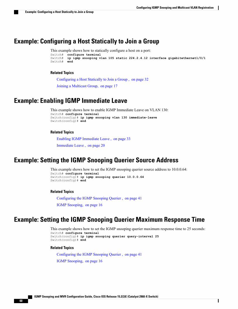
Example: Configuring a Host Statically to Join a GroupThis example shows how to statically configure a host on a port:Switch# configure terminalSwitch# ip igmp snooping vlan 105 static 224.2.4.12 interface gigabitethernet1/0/1Switch# end
Related Topics
Configuring a Host Statically to Join a Group , on page 32
Joining a Multicast Group, on page 17
Example: Enabling IGMP Immediate LeaveThis example shows how to enable IGMP Immediate Leave on VLAN 130:Switch# configure terminalSwitch(config)# ip igmp snooping vlan 130 immediate-leaveSwitch(config)# end
Related Topics
Enabling IGMP Immediate Leave , on page 33
Immediate Leave , on page 20
Example: Setting the IGMP Snooping Querier Source AddressThis example shows how to set the IGMP snooping querier source address to 10.0.0.64:Switch# configure terminalSwitch(config)# ip igmp snooping querier 10.0.0.64Switch(config)# end
Related Topics
Configuring the IGMP Snooping Querier , on page 41
IGMP Snooping, on page 16
Example: Setting the IGMP Snooping Querier Maximum Response TimeThis example shows how to set the IGMP snooping querier maximum response time to 25 seconds:Switch# configure terminalSwitch(config)# ip igmp snooping querier query-interval 25Switch(config)# end
Related Topics
Configuring the IGMP Snooping Querier , on page 41
IGMP Snooping, on page 16
IGMP Snooping and MVR Configuration Guide, Cisco IOS Release 15.2(3)E (Catalyst 2960-X Switch)60
Configuring IGMP Snooping and Multicast VLAN RegistrationExample: Configuring a Host Statically to Join a Group
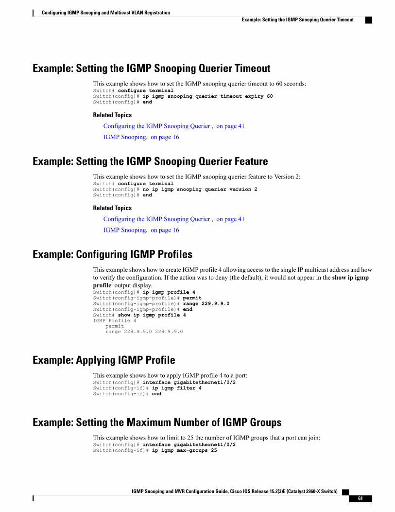
Example: Setting the IGMP Snooping Querier TimeoutThis example shows how to set the IGMP snooping querier timeout to 60 seconds:Switch# configure terminalSwitch(config)# ip igmp snooping querier timeout expiry 60Switch(config)# end
Related Topics
Configuring the IGMP Snooping Querier , on page 41
IGMP Snooping, on page 16
Example: Setting the IGMP Snooping Querier FeatureThis example shows how to set the IGMP snooping querier feature to Version 2:Switch# configure terminalSwitch(config)# no ip igmp snooping querier version 2Switch(config)# end
Related Topics
Configuring the IGMP Snooping Querier , on page 41
IGMP Snooping, on page 16
Example: Configuring IGMP ProfilesThis example shows how to create IGMP profile 4 allowing access to the single IP multicast address and howto verify the configuration. If the action was to deny (the default), it would not appear in the show ip igmpprofile output display.Switch(config)# ip igmp profile 4Switch(config-igmp-profile)# permitSwitch(config-igmp-profile)# range 229.9.9.0Switch(config-igmp-profile)# endSwitch# show ip igmp profile 4IGMP Profile 4
permitrange 229.9.9.0 229.9.9.0
Example: Applying IGMP ProfileThis example shows how to apply IGMP profile 4 to a port:Switch(config)# interface gigabitethernet1/0/2Switch(config-if)# ip igmp filter 4Switch(config-if)# end
Example: Setting the Maximum Number of IGMP GroupsThis example shows how to limit to 25 the number of IGMP groups that a port can join:Switch(config)# interface gigabitethernet1/0/2Switch(config-if)# ip igmp max-groups 25
IGMP Snooping and MVR Configuration Guide, Cisco IOS Release 15.2(3)E (Catalyst 2960-X Switch) 61
Configuring IGMP Snooping and Multicast VLAN RegistrationExample: Setting the IGMP Snooping Querier Timeout
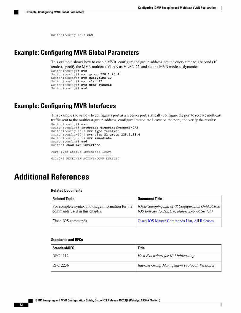
Switch(config-if)# end
Example: Configuring MVR Global ParametersThis example shows how to enable MVR, configure the group address, set the query time to 1 second (10tenths), specify the MVR multicast VLAN as VLAN 22, and set the MVR mode as dynamic:Switch(config)# mvrSwitch(config)# mvr group 228.1.23.4Switch(config)# mvr querytime 10Switch(config)# mvr vlan 22Switch(config)# mvr mode dynamicSwitch(config)# end
Example: Configuring MVR InterfacesThis example shows how to configure a port as a receiver port, statically configure the port to receive multicasttraffic sent to the multicast group address, configure Immediate Leave on the port, and verify the results:Switch(config)# mvrSwitch(config)# interface gigabitethernet1/0/2Switch(config-if)# mvr type receiverSwitch(config-if)# mvr vlan 22 group 228.1.23.4Switch(config-if)# mvr immediateSwitch(config)# endSwitch# show mvr interface
Port Type Status Immediate Leave---- ---- ------- ---------------Gi1/0/2 RECEIVER ACTIVE/DOWN ENABLED
Additional ReferencesRelated Documents
Document TitleRelated Topic
IGMPSnooping andMVRConfigurationGuide,CiscoIOS Release 15.2(2)E (Catalyst 2960-X Switch)
For complete syntax and usage information for thecommands used in this chapter.
Cisco IOS Master Commands List, All ReleasesCisco IOS commands
Standards and RFCs
TitleStandard/RFC
Host Extensions for IP MulticastingRFC 1112
Internet Group Management Protocol, Version 2RFC 2236
IGMP Snooping and MVR Configuration Guide, Cisco IOS Release 15.2(3)E (Catalyst 2960-X Switch)62
Configuring IGMP Snooping and Multicast VLAN RegistrationExample: Configuring MVR Global Parameters
MIBs
MIBs LinkMIB
To locate and downloadMIBs for selected platforms,Cisco IOS releases, and feature sets, use Cisco MIBLocator found at the following URL:
http://www.cisco.com/go/mibs
All supported MIBs for this release.
Technical Assistance
LinkDescription
http://www.cisco.com/supportThe Cisco Support website provides extensive onlineresources, including documentation and tools fortroubleshooting and resolving technical issues withCisco products and technologies.
To receive security and technical information aboutyour products, you can subscribe to various services,such as the Product Alert Tool (accessed from FieldNotices), the Cisco Technical Services Newsletter,and Really Simple Syndication (RSS) Feeds.
Access to most tools on the Cisco Support websiterequires a Cisco.com user ID and password.
Feature History and Information for IGMP SnoopingModificationRelease
This feature was introduced.Cisco IOS 15.0(2)EX
IGMP Snooping and MVR Configuration Guide, Cisco IOS Release 15.2(3)E (Catalyst 2960-X Switch) 63
Configuring IGMP Snooping and Multicast VLAN RegistrationFeature History and Information for IGMP Snooping

IGMP Snooping and MVR Configuration Guide, Cisco IOS Release 15.2(3)E (Catalyst 2960-X Switch)64
Configuring IGMP Snooping and Multicast VLAN RegistrationFeature History and Information for IGMP Snooping
I N D E X
A
address aliasing 16
C
compatible mode 22configurable leave timer, IGMP 20
D
default configuration 21, 24, 25, 26IGMP filtering 25IGMP snooping 21IGMP throttling 26MVR 24
dynamic mode 22
F
feature information 63IGMP snooping 63
G
global leave, IGMP 38
I
IGMP 17, 18, 19, 20, 22, 35, 36, 38, 39, 43configurable leave timer 20, 35
described 20configurable leave timer 20, 35
enabling 35flooded multicast traffic 36, 38, 39
controlling the length of time 36
IGMP (continued)flooded multicast traffic (continued)
disabling on an interface 39global leave 38recovering from flood mode 38
join messages 17leaving multicast group 19queries 18report suppression 20, 43
described 20disabling 43
supported versions 17IGMP filtering 25
default configuration 25described 25
IGMP groups 53, 55configuring filtering 55setting the maximum number 53
IGMP Immediate Leave 15, 33enabling 33
IGMP profile 49, 52applying 52configuration mode 49
IGMP report suppression 14IGMP snooping 13, 16, 17, 20, 21, 26, 27, 41
and address aliasing 16and stack changes 21default configuration 21definition 16enabling and disabling 26global configuration 26Immediate Leave 20in the switch stack 21querier 13, 41
configuration guidelines 13configuring 41
supported versions 17VLAN configuration 27
IGMP throttling 25, 26, 55, 59configuring 55default configuration 26described 25
IGMP Snooping and MVR Configuration Guide, Cisco IOS Release 15.2(3)E (Catalyst 2960-X Switch) IN-1
IGMP throttling (continued)displaying action 59
IGMP Throttling Action 15configuration guidelines 15
Immediate Leave, IGMP 20described 20
J
join messages, IGMP 17
M
monitoring 58multicast router interfaces 58
multicast groups 17, 19, 32joining 17leaving 19static joins 32
multicast router interfaces, monitoring 58multicast router ports, adding 30multicast television application 23MVR 22, 24
default configuration 24described 22
MVR interfaces 47MVR parameters 44
P
prerequisites 13IGMP snooping 13
Q
queries, IGMP 18
R
report suppression, IGMP 20, 43described 20disabling 43
restrictions 14, 15IGMP snooping 14
RFC 161112, IP multicast and IGMP 16
S
stack changes, effects on 21IGMP snooping 21
stacks 22
IGMP Snooping and MVR Configuration Guide, Cisco IOS Release 15.2(3)E (Catalyst 2960-X Switch)IN-2
Index