Embed Size (px)
Citation preview
IgH Master 1.5.0
Documentation
Dipl.-Ing. (FH) Florian Pose, [email protected]
Ingenieurgemeinschaft
Essen, April 30, 2010
Revision 6129a5f715fb

ii 6129a5f715fb, 2010/04/30
Contents
Conventions . . . . . . . . . . . . . . . . . . . . . . . . . . . . . . . . . . . . x
1 The IgH EtherCAT Master 11.1 Feature Summary . . . . . . . . . . . . . . . . . . . . . . . . . . . . . . 11.2 License . . . . . . . . . . . . . . . . . . . . . . . . . . . . . . . . . . . . 3
2 Architecture 52.1 Master Module . . . . . . . . . . . . . . . . . . . . . . . . . . . . . . . 72.2 Master Phases . . . . . . . . . . . . . . . . . . . . . . . . . . . . . . . . 82.3 Process Data . . . . . . . . . . . . . . . . . . . . . . . . . . . . . . . . 8
3 Application Interface 113.1 Master Configuration . . . . . . . . . . . . . . . . . . . . . . . . . . . . 11
3.1.1 Slave Configuration . . . . . . . . . . . . . . . . . . . . . . . . . 113.2 Cyclic Operation . . . . . . . . . . . . . . . . . . . . . . . . . . . . . . 133.3 VoE Handlers . . . . . . . . . . . . . . . . . . . . . . . . . . . . . . . . 133.4 Concurrent Master Access . . . . . . . . . . . . . . . . . . . . . . . . . 143.5 Distributed Clocks . . . . . . . . . . . . . . . . . . . . . . . . . . . . . 15
4 Ethernet Devices 194.1 Network Driver Basics . . . . . . . . . . . . . . . . . . . . . . . . . . . 194.2 Native EtherCAT Device Drivers . . . . . . . . . . . . . . . . . . . . . 214.3 Generic EtherCAT Device Driver . . . . . . . . . . . . . . . . . . . . . 234.4 Providing Ethernet Devices . . . . . . . . . . . . . . . . . . . . . . . . 244.5 EtherCAT Device Interface . . . . . . . . . . . . . . . . . . . . . . . . . 244.6 Patching Native Network Drivers . . . . . . . . . . . . . . . . . . . . . 24
5 State Machines 275.1 State Machine Theory . . . . . . . . . . . . . . . . . . . . . . . . . . . 285.2 The Master’s State Model . . . . . . . . . . . . . . . . . . . . . . . . . 305.3 The Master State Machine . . . . . . . . . . . . . . . . . . . . . . . . . 335.4 The Slave Scan State Machine . . . . . . . . . . . . . . . . . . . . . . . 335.5 The Slave Configuration State Machine . . . . . . . . . . . . . . . . . . 365.6 The State Change State Machine . . . . . . . . . . . . . . . . . . . . . 365.7 The SII State Machine . . . . . . . . . . . . . . . . . . . . . . . . . . . 395.8 The PDO State Machines . . . . . . . . . . . . . . . . . . . . . . . . . 40
6129a5f715fb, 2010/04/30 iii
6 Mailbox Protocol Implementations 456.1 Ethernet over EtherCAT (EoE) . . . . . . . . . . . . . . . . . . . . . . 456.2 CANopen over EtherCAT (CoE) . . . . . . . . . . . . . . . . . . . . . 476.3 Vendor specific over EtherCAT (VoE) . . . . . . . . . . . . . . . . . . . 496.4 Servo Profile over EtherCAT (SoE) . . . . . . . . . . . . . . . . . . . . 49
7 Userspace Interfaces 517.1 Command-line Tool . . . . . . . . . . . . . . . . . . . . . . . . . . . . . 51
7.1.1 Character Devices . . . . . . . . . . . . . . . . . . . . . . . . . . 517.1.2 Setting Alias Addresses . . . . . . . . . . . . . . . . . . . . . . . 527.1.3 Displaying the Bus Configuration . . . . . . . . . . . . . . . . . 527.1.4 Output PDO information in C Language . . . . . . . . . . . . . 537.1.5 Displaying Process Data . . . . . . . . . . . . . . . . . . . . . . 537.1.6 Setting a Master’s Debug Level . . . . . . . . . . . . . . . . . . 547.1.7 Configured Domains . . . . . . . . . . . . . . . . . . . . . . . . 547.1.8 SDO Access . . . . . . . . . . . . . . . . . . . . . . . . . . . . . 557.1.9 EoE Statistics . . . . . . . . . . . . . . . . . . . . . . . . . . . . 567.1.10 File-Access over EtherCAT . . . . . . . . . . . . . . . . . . . . . 567.1.11 Creating Topology Graphs . . . . . . . . . . . . . . . . . . . . . 577.1.12 Master and Ethernet Devices . . . . . . . . . . . . . . . . . . . 587.1.13 Sync Managers, PDOs and PDO Entries . . . . . . . . . . . . . 587.1.14 Register Access . . . . . . . . . . . . . . . . . . . . . . . . . . . 597.1.15 SDO Dictionary . . . . . . . . . . . . . . . . . . . . . . . . . . . 607.1.16 SII Access . . . . . . . . . . . . . . . . . . . . . . . . . . . . . . 617.1.17 Slaves on the Bus . . . . . . . . . . . . . . . . . . . . . . . . . . 627.1.18 SoE IDN Access . . . . . . . . . . . . . . . . . . . . . . . . . . . 647.1.19 Requesting Application-Layer States . . . . . . . . . . . . . . . 657.1.20 Displaying the Master Version . . . . . . . . . . . . . . . . . . . 657.1.21 Generating Slave Description XML . . . . . . . . . . . . . . . . 66
7.2 Userspace Library . . . . . . . . . . . . . . . . . . . . . . . . . . . . . . 667.2.1 Using the Library . . . . . . . . . . . . . . . . . . . . . . . . . . 667.2.2 Implementation . . . . . . . . . . . . . . . . . . . . . . . . . . . 677.2.3 Timing . . . . . . . . . . . . . . . . . . . . . . . . . . . . . . . . 67
7.3 System Integration . . . . . . . . . . . . . . . . . . . . . . . . . . . . . 687.3.1 Init Script . . . . . . . . . . . . . . . . . . . . . . . . . . . . . . 687.3.2 Sysconfig File . . . . . . . . . . . . . . . . . . . . . . . . . . . . 697.3.3 Starting the Master as a Service . . . . . . . . . . . . . . . . . . 69
7.4 Debug Interfaces . . . . . . . . . . . . . . . . . . . . . . . . . . . . . . 70
8 Timing Aspects 738.0.1 Application Interface Profiling . . . . . . . . . . . . . . . . . . . 738.0.2 Bus Cycle Measuring . . . . . . . . . . . . . . . . . . . . . . . . 74
9 Installation 77
iv 6129a5f715fb, 2010/04/30
9.1 Getting the Software . . . . . . . . . . . . . . . . . . . . . . . . . . . . 779.2 Building the Software . . . . . . . . . . . . . . . . . . . . . . . . . . . . 779.3 Building the Interface Documentation . . . . . . . . . . . . . . . . . . . 789.4 Installing the Software . . . . . . . . . . . . . . . . . . . . . . . . . . . 789.5 Automatic Device Node Creation . . . . . . . . . . . . . . . . . . . . . 81
Bibliography 83
Glossary 83
6129a5f715fb, 2010/04/30 v

vi 6129a5f715fb, 2010/04/30
List of Tables
3.1 Specifying a Slave Position . . . . . . . . . . . . . . . . . . . . . . . . . 12
5.1 A typical state transition table . . . . . . . . . . . . . . . . . . . . . . . 29
7.1 Application Interface Timing Comparison . . . . . . . . . . . . . . . . 68
8.1 Profiling of an Application Cycle on a 2.0 GHz Processor . . . . . . . . 73
9.1 Configuration options . . . . . . . . . . . . . . . . . . . . . . . . . . . . 79
6129a5f715fb, 2010/04/30 vii

viii 6129a5f715fb, 2010/04/30
List of Figures
2.1 Master Architecture . . . . . . . . . . . . . . . . . . . . . . . . . . . . . 62.2 Multiple masters in one module . . . . . . . . . . . . . . . . . . . . . . 72.3 Master phases and transitions . . . . . . . . . . . . . . . . . . . . . . . 82.4 FMMU Configuration . . . . . . . . . . . . . . . . . . . . . . . . . . . . 10
3.1 Master Configuration . . . . . . . . . . . . . . . . . . . . . . . . . . . . 123.2 Slave Configuration Attachment . . . . . . . . . . . . . . . . . . . . . . 133.3 Concurrent Master Access . . . . . . . . . . . . . . . . . . . . . . . . . 143.4 Distributed Clocks . . . . . . . . . . . . . . . . . . . . . . . . . . . . . 15
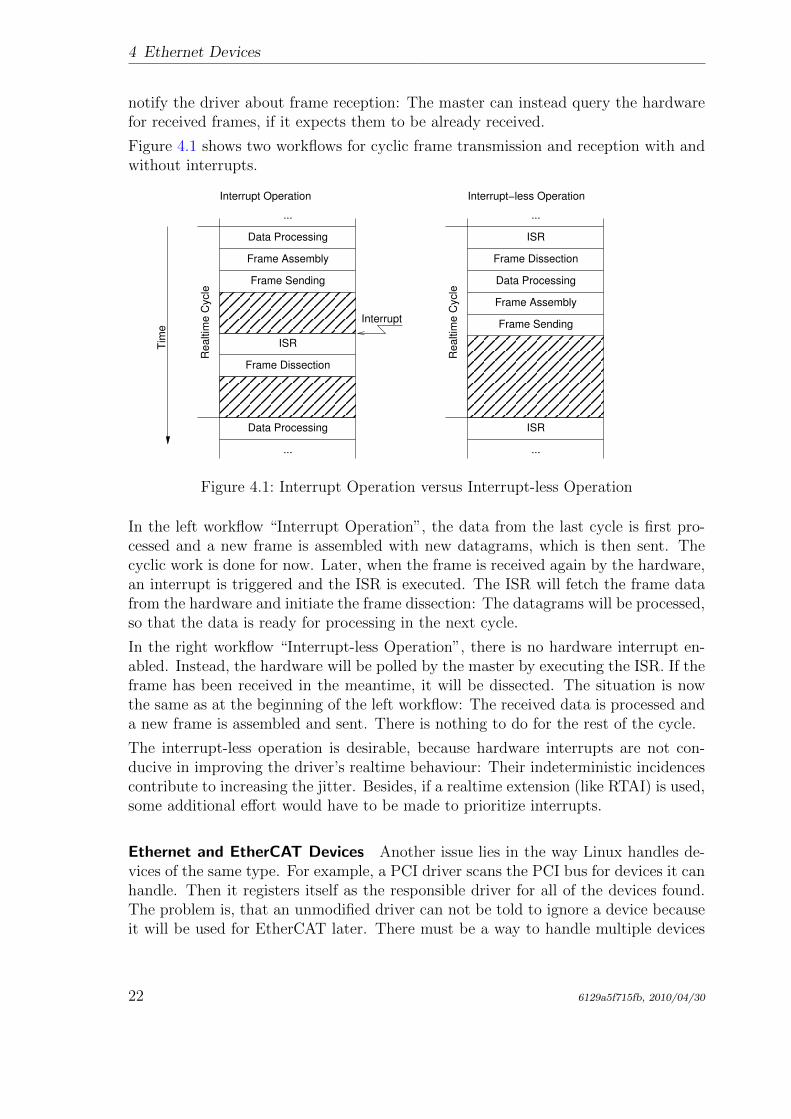
4.1 Interrupt Operation versus Interrupt-less Operation . . . . . . . . . . . 22
5.1 A typical state transition diagram . . . . . . . . . . . . . . . . . . . . . 295.2 Transition diagram of the master state machine . . . . . . . . . . . . . 345.3 Transition diagram of the slave scan state machine . . . . . . . . . . . 355.4 Transition diagram of the slave configuration state machine . . . . . . . 375.5 Transition Diagram of the State Change State Machine . . . . . . . . . 385.6 Transition Diagram of the SII State Machine . . . . . . . . . . . . . . . 395.7 Transition Diagram of the PDO Reading State Machine . . . . . . . . . 415.8 Transition Diagram of the PDO Entry Reading State Machine . . . . . 415.9 Transition Diagram of the PDO Configuration State Machine . . . . . . 425.10 Transition Diagram of the PDO Entry Configuration State Machine . . 43
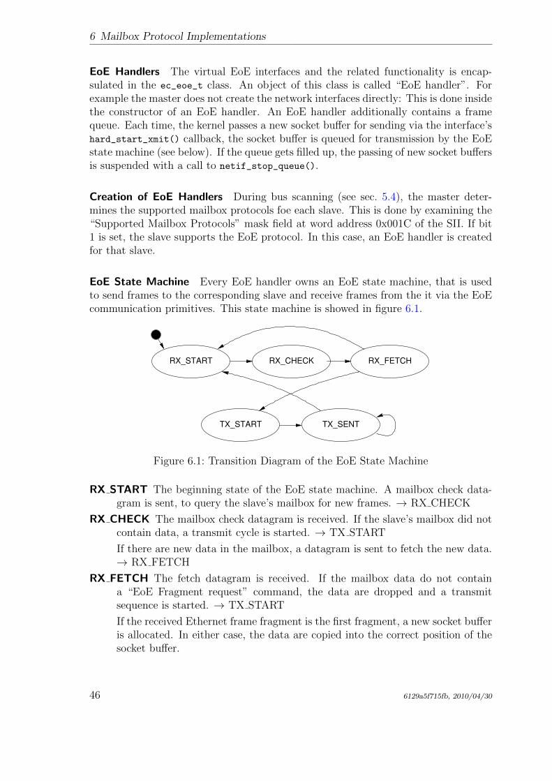
6.1 Transition Diagram of the EoE State Machine . . . . . . . . . . . . . . 466.2 Transition diagram of the CoE download state machine . . . . . . . . . 48
6129a5f715fb, 2010/04/30 ix
Conventions
Conventions
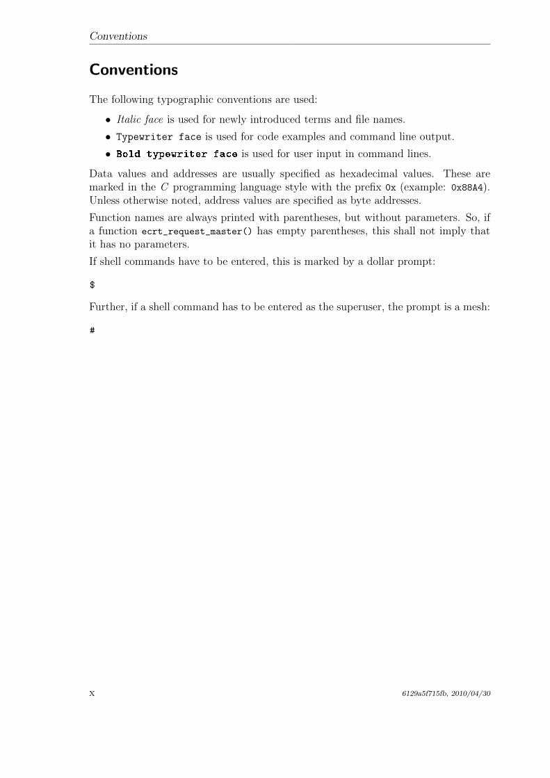
The following typographic conventions are used:
• Italic face is used for newly introduced terms and file names.
• Typewriter face is used for code examples and command line output.
• Bold typewriter face is used for user input in command lines.
Data values and addresses are usually specified as hexadecimal values. These aremarked in the C programming language style with the prefix 0x (example: 0x88A4).Unless otherwise noted, address values are specified as byte addresses.
Function names are always printed with parentheses, but without parameters. So, ifa function ecrt_request_master() has empty parentheses, this shall not imply thatit has no parameters.
If shell commands have to be entered, this is marked by a dollar prompt:
$
Further, if a shell command has to be entered as the superuser, the prompt is a mesh:
#
x 6129a5f715fb, 2010/04/30
1 The IgH EtherCAT Master
This chapter covers some general information about the EtherCAT master.
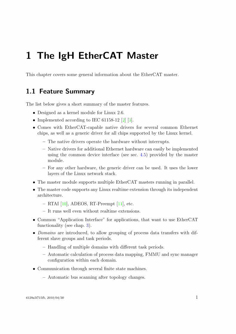
1.1 Feature Summary
The list below gives a short summary of the master features.
• Designed as a kernel module for Linux 2.6.
• Implemented according to IEC 61158-12 [2] [3].
• Comes with EtherCAT-capable native drivers for several common Ethernetchips, as well as a generic driver for all chips supported by the Linux kernel.
– The native drivers operate the hardware without interrupts.
– Native drivers for additional Ethernet hardware can easily be implementedusing the common device interface (see sec. 4.5) provided by the mastermodule.
– For any other hardware, the generic driver can be used. It uses the lowerlayers of the Linux network stack.
• The master module supports multiple EtherCAT masters running in parallel.
• The master code supports any Linux realtime extension through its independentarchitecture.
– RTAI [10], ADEOS, RT-Preempt [11], etc.
– It runs well even without realtime extensions.
• Common “Application Interface” for applications, that want to use EtherCATfunctionality (see chap. 3).
• Domains are introduced, to allow grouping of process data transfers with dif-ferent slave groups and task periods.
– Handling of multiple domains with different task periods.
– Automatic calculation of process data mapping, FMMU and sync managerconfiguration within each domain.
• Communication through several finite state machines.
– Automatic bus scanning after topology changes.
6129a5f715fb, 2010/04/30 1
1 The IgH EtherCAT Master
– Bus monitoring during operation.
– Automatic reconfiguration of slaves (for example after power failure) duringoperation.
• Distributed Clocks support (see sec. 3.5).
– Configuration of the slave’s DC parameters through the application inter-face.
– Synchronization (offset and drift compensation) of the distributed slaveclocks to the reference clock.
– Optional synchronization of the reference clock to the master clock.
• CANopen over EtherCAT (CoE)
– SDO upload, download and information service.
– Slave configuration via SDOs.
– SDO access from userspace and from the application.
• Ethernet over EtherCAT (EoE)
– Transparent use of EoE slaves via virtual network interfaces.
– Natively supports either a switched or a routed EoE network architecture.
• Vendor-specific over EtherCAT (VoE)
– Communication with vendor-specific mailbox protocols via the API.
• File Access over EtherCAT (FoE)
– Loading and storing files via the command-line tool.
– Updating a slave’s firmware can be done easily.
• Servo Profile over EtherCAT (SoE)
– Implemented according to IEC 61800-7 [15].
– Storing IDN configurations, that are written to the slave during startup.
– Accessing IDNs via the command-line tool.
– Accessing IDNs at runtime via the the user-space library.
• Userspace command-line-tool “ethercat” (see sec. 7.1)
– Detailed information about master, slaves, domains and bus configuration.
– Setting the master’s debug level.
– Reading/Writing alias addresses.
– Listing slave configurations.
– Viewing process data.
– SDO download/upload; listing SDO dictionaries.
2 6129a5f715fb, 2010/04/30
1.2 License
– Loading and storing files via FoE.
– SoE IDN access.
– Access to slave registers.
– Slave SII (EEPROM) access.
– Controlling application-layer states.
– Generation of slave description XML and C-code from existing slaves.
• Seamless system integration though LSB compliance.
– Master and network device configuration via sysconfig files.
– Init script for master control.
• Virtual read-only network interface for monitoring and debugging purposes.
1.2 License
The master code is released under the terms and conditions of the GNU General PublicLicense (GPL [4]), version 2. Other developers, that want to use EtherCAT with Linuxsystems, are invited to use the master code or even participate on development.
To allow static linking of userspace application against the master’s application inter-face (see chap. 3), the userspace library (see sec. 7.2) is licensed under the terms andconditions of the GNU Lesser General Public License (LGPL [5]), version 2.1.
6129a5f715fb, 2010/04/30 3

1 The IgH EtherCAT Master
4 6129a5f715fb, 2010/04/30
2 Architecture
The EtherCAT master is integrated into the Linux 2.6 kernel. This was an earlydesign decision, which has been made for several reasons:
• Kernel code has significantly better realtime characteristics, i. e. less latencythan userspace code. It was foreseeable, that a fieldbus master has a lot ofcyclic work to do. Cyclic work is usually triggered by timer interrupts insidethe kernel. The execution delay of a function that processes timer interrupts isless, when it resides in kernelspace, because there is no need of time-consumingcontext switches to a userspace process.
• It was also foreseeable, that the master code has to directly communicate withthe Ethernet hardware. This has to be done in the kernel anyway (throughnetwork device drivers), which is one more reason for the master code being inkernelspace.
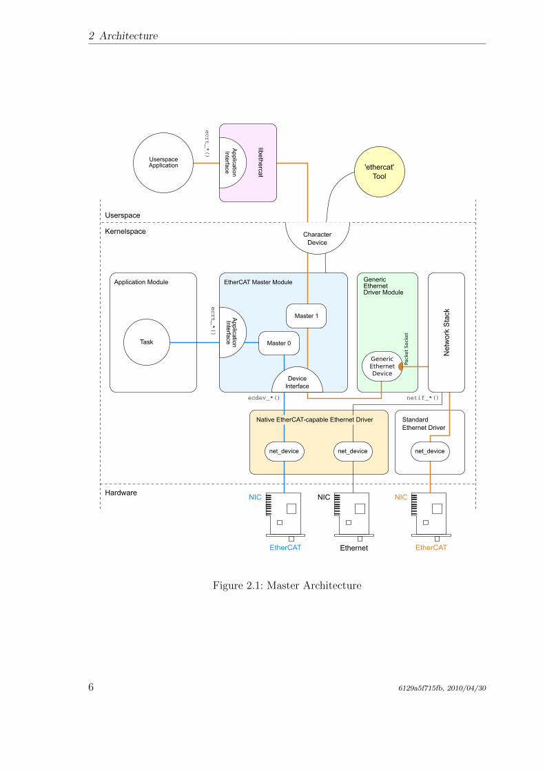
Figure 2.1 gives a general overview of the master architecture.
The components of the master environment are described below:
Master Module Kernel module containing one or more EtherCAT master instances(see sec. 2.1), the “Device Interface” (see sec. 4.5) and the “Application Inter-face” (see chap. 3).
Device Modules EtherCAT-capable Ethernet device driver modules, that offer theirdevices to the EtherCAT master via the device interface (see sec. 4.5). Thesemodified network drivers can handle network devices used for EtherCAT oper-ation and “normal” Ethernet devices in parallel. A master can accept a certaindevice and then is able to send and receive EtherCAT frames. Ethernet devicesdeclined by the master module are connected to the kernel’s network stack asusual.
Application A program that uses the EtherCAT master (usually for cyclic exchangeof process data with EtherCAT slaves). These programs are not part of theEtherCAT master code1, but have to be generated or written by the user.An application can “request” a master through the application interface (seechap. 3). If this succeeds, it has the control over the master: It can provide abus configuration and exchange process data. Applications can be kernel mod-ules (that use the kernel application interface directly) or userspace programs,that use the application interface via the EtherCAT library (see sec. 7.2).
1Although there are some examples provided in the examples/ directory.
6129a5f715fb, 2010/04/30 5
2 Architecture
ecdev_*()
EtherCAT Master Module
EtherCAT Ethernet
NIC NICHardware
ecrt_*()
Application Module
Task
Kernelspace
Userspace
ecrt_*()
netif_*()
ApplicationInterface
GenericEthernetDriver Module
StandardEthernet Driver
NIC
UserspaceApplication
libethercat
ApplicationInterface 'ethercat'
Tool
CharacterDevice
DeviceInterface
Net
wor
k S
tack
net_devicenet_device
Native EtherCAT-capable Ethernet Driver
net_device
EtherCAT
GenericEthernetDevice
Pack
et
Sock
et
Master 0
Master 1
Figure 2.1: Master Architecture
6 6129a5f715fb, 2010/04/30
2.1 Master Module
2.1 Master Module
The EtherCAT master kernel module ec master can contain multiple master instances.Each master waits for a certain Ethernet device identified by its MAC address. Theseaddresses have to be specified on module loading via the main devices module param-eter. The number of master instances to initialize is taken from the number of MACaddresses given.
The below command loads the master module with a single master instance that waitsfor the Ethernet device with the MAC address 00:0E:0C:DA:A2:20. The master willbe accessible via index 0.
# modprobe ec master main devices=00:0E:0C:DA:A2:20
MAC addresses for multiple masters have to be separated by commas:
# modprobe ec master main devices=00:0E:0C:DA:A2:20,00:e0:81:71:d5:1c
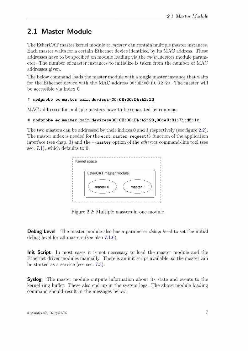
The two masters can be addressed by their indices 0 and 1 respectively (see figure 2.2).The master index is needed for the ecrt_master_request() function of the applicationinterface (see chap. 3) and the --master option of the ethercat command-line tool (seesec. 7.1), which defaults to 0.
master 0 master 1
EtherCAT master module
Kernel space
Figure 2.2: Multiple masters in one module
Debug Level The master module also has a parameter debug level to set the initialdebug level for all masters (see also 7.1.6).
Init Script In most cases it is not necessary to load the master module and theEthernet driver modules manually. There is an init script available, so the master canbe started as a service (see sec. 7.3).
Syslog The master module outputs information about its state and events to thekernel ring buffer. These also end up in the system logs. The above module loadingcommand should result in the messages below:
6129a5f715fb, 2010/04/30 7
2 Architecture
# dmesg | tail -2
EtherCAT: Master driver 1.5.0
EtherCAT: 2 masters waiting for devices.
# tail -2 /var/log/messages
Jul 4 10:22:45 ethercat kernel: EtherCAT: Master driver 1.5.0
Jul 4 10:22:45 ethercat kernel: EtherCAT: 2 masters waiting
for devices.
All EtherCAT master output is prefixed with EtherCAT which makes searching thelogs easier.
2.2 Master Phases
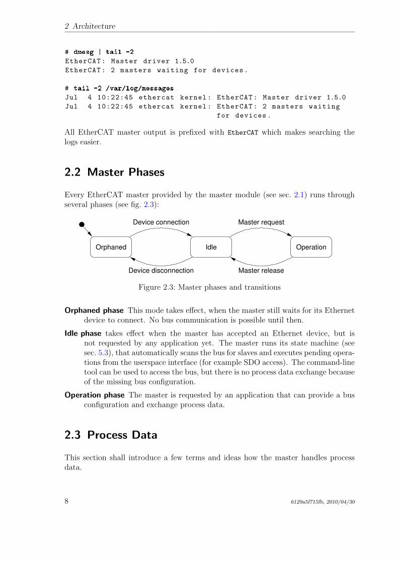
Every EtherCAT master provided by the master module (see sec. 2.1) runs throughseveral phases (see fig. 2.3):
Orphaned Idle Operation
Device connection Master request
Device disconnection Master release
Figure 2.3: Master phases and transitions
Orphaned phase This mode takes effect, when the master still waits for its Ethernetdevice to connect. No bus communication is possible until then.
Idle phase takes effect when the master has accepted an Ethernet device, but isnot requested by any application yet. The master runs its state machine (seesec. 5.3), that automatically scans the bus for slaves and executes pending opera-tions from the userspace interface (for example SDO access). The command-linetool can be used to access the bus, but there is no process data exchange becauseof the missing bus configuration.
Operation phase The master is requested by an application that can provide a busconfiguration and exchange process data.
2.3 Process Data
This section shall introduce a few terms and ideas how the master handles processdata.
8 6129a5f715fb, 2010/04/30
2.3 Process Data
Process Data Image Slaves offer their inputs and outputs by presenting the mas-ter so-called “Process Data Objects” (PDOs). The available PDOs can be eitherdetermined by reading out the slave’s TXPDO and RXPDO SII categories from theE2PROM (in case of fixed PDOs) or by reading out the appropriate CoE objects (seesec. 6.2), if available. The application can register the PDOs’ entries for exchangeduring cyclic operation. The sum of all registered PDO entries defines the “processdata image”, which is exchanged via datagrams with “logical” memory access (likeLWR, LRD or LRW) introduced in [2, sec. 5.4].
Process Data Domains The process data image can be easily managed by creat-ing so-called “domains”, which allow grouped PDO exchange. They also take careof managing the datagram structures needed to exchange the PDOs. Domains aremandatory for process data exchange, so there has to be at least one. They wereintroduced for the following reasons:
• The maximum size of a datagram is limited due to the limited size of an Eth-ernet frame: The maximum data size is the Ethernet data field size minus theEtherCAT frame header, EtherCAT datagram header and EtherCAT datagramfooter: 1500 − 2 − 12 − 2 = 1484 octets. If the size of the process data imageexceeds this limit, multiple frames have to be sent, and the image has to bepartitioned for the use of multiple datagrams. A domain manages this auto-matically.
• Not every PDO has to be exchanged with the same frequency: The values ofPDOs can vary slowly over time (for example temperature values), so exchangingthem with a high frequency would just waste bus bandwidth. For this reason,multiple domains can be created, to group different PDOs and so allow separateexchange.
There is no upper limit for the number of domains, but each domain occupies oneFMMU in each slave involved, so the maximum number of domains is de facto limitedby the slaves.
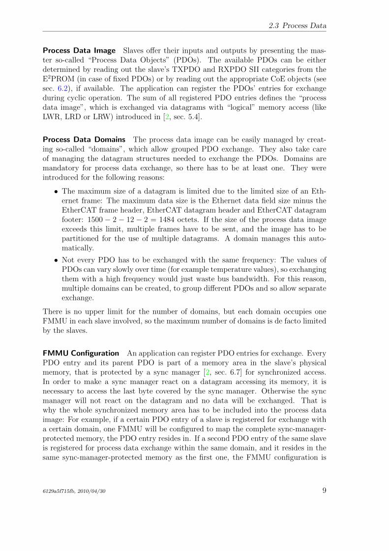
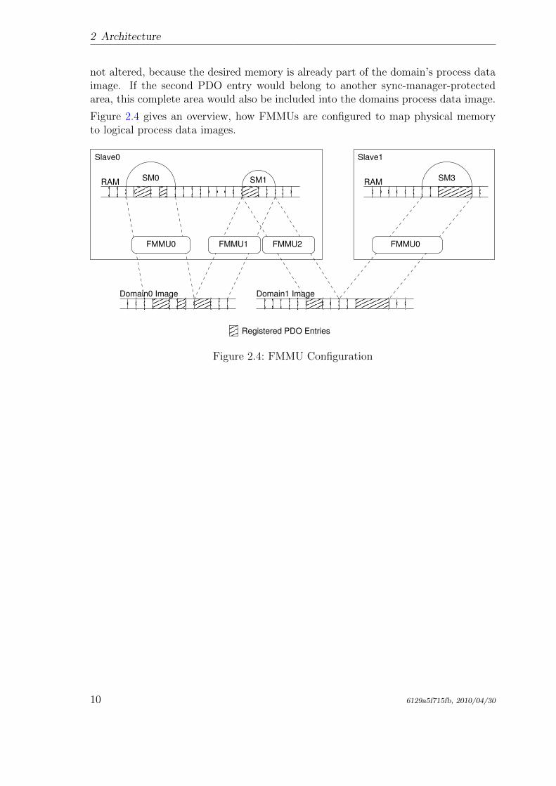
FMMU Configuration An application can register PDO entries for exchange. EveryPDO entry and its parent PDO is part of a memory area in the slave’s physicalmemory, that is protected by a sync manager [2, sec. 6.7] for synchronized access.In order to make a sync manager react on a datagram accessing its memory, it isnecessary to access the last byte covered by the sync manager. Otherwise the syncmanager will not react on the datagram and no data will be exchanged. That iswhy the whole synchronized memory area has to be included into the process dataimage: For example, if a certain PDO entry of a slave is registered for exchange witha certain domain, one FMMU will be configured to map the complete sync-manager-protected memory, the PDO entry resides in. If a second PDO entry of the same slaveis registered for process data exchange within the same domain, and it resides in thesame sync-manager-protected memory as the first one, the FMMU configuration is
6129a5f715fb, 2010/04/30 9
2 Architecture
not altered, because the desired memory is already part of the domain’s process dataimage. If the second PDO entry would belong to another sync-manager-protectedarea, this complete area would also be included into the domains process data image.
Figure 2.4 gives an overview, how FMMUs are configured to map physical memoryto logical process data images.
Registered PDO Entries
RAM SM1 RAM
Slave0 Slave1
FMMU0FMMU0 FMMU1 FMMU2
SM0 SM3
Domain0 Image Domain1 Image
Figure 2.4: FMMU Configuration
10 6129a5f715fb, 2010/04/30
3 Application Interface
The application interface provides functions and data structures for applications toaccess an EtherCAT master. The complete documentation of the interface is includedas Doxygen [12] comments in the header file include/ecrt.h. It can either be readdirectly from the file comments, or as a more comfortable HTML documentation.The HTML generation is described in sec. 9.3.
The following sections cover a general description of the application interface.
Every application should use the master in two steps:
Configuration The master is requested and the configuration is applied. For example,domains are created, slaves are configured and PDO entries are registered (seesec. 3.1).
Operation Cyclic code is run and process data are exchanged (see sec. 3.2).
Example Applications There are a few example applications in the examples/ sub-directory of the master code. They are documented in the source code.
3.1 Master Configuration
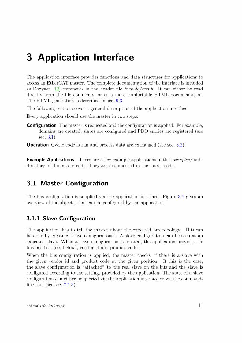
The bus configuration is supplied via the application interface. Figure 3.1 gives anoverview of the objects, that can be configured by the application.
3.1.1 Slave Configuration
The application has to tell the master about the expected bus topology. This canbe done by creating “slave configurations”. A slave configuration can be seen as anexpected slave. When a slave configuration is created, the application provides thebus position (see below), vendor id and product code.
When the bus configuration is applied, the master checks, if there is a slave withthe given vendor id and product code at the given position. If this is the case,the slave configuration is “attached” to the real slave on the bus and the slave isconfigured according to the settings provided by the application. The state of a slaveconfiguration can either be queried via the application interface or via the command-line tool (see sec. 7.1.3).
6129a5f715fb, 2010/04/30 11
3 Application Interface
n
n
n
n
Master
Index
n
Domain
n nSlave Configuration
Alias
Position
Vendor ID
Product Code
Sync Manager
Index
Direction
SDO Configuration
Index
Subindex
Data
SDO Request
Index
Subindex
PDO
Index
PDO Entry
Index
Subindex
Bitlength
n
Figure 3.1: Master Configuration
Slave Position The slave position has to be specified as a tuple of “alias” and“position”. This allows addressing slaves either via an absolute bus position, or astored identifier called “alias”, or a mixture of both. The alias is a 16-bit value storedin the slave’s E2PROM. It can be modified via the command-line tool (see sec. 7.1.2).Table 3.1 shows, how the values are interpreted.
Table 3.1: Specifying a Slave Position
Alias Position Interpretation0 0 – 65535 Position addressing. The position pa-
rameter is interpreted as the absolutering position in the bus.
1 – 65535 0 – 65535 Alias addressing. The position param-eter is interpreted as relative positionafter the first slave with the given aliasaddress.
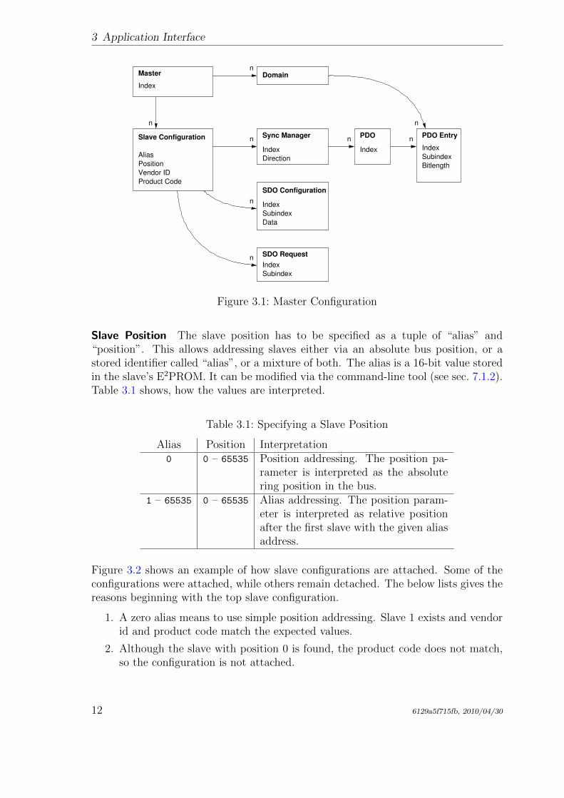
Figure 3.2 shows an example of how slave configurations are attached. Some of theconfigurations were attached, while others remain detached. The below lists gives thereasons beginning with the top slave configuration.
1. A zero alias means to use simple position addressing. Slave 1 exists and vendorid and product code match the expected values.
2. Although the slave with position 0 is found, the product code does not match,so the configuration is not attached.
12 6129a5f715fb, 2010/04/30
3.2 Cyclic Operation
Vendor:
Product:
Alias:
0x00000001
0x00000001
0x0000
Vendor:
Product:
Alias:
0x00000002
0x00000004
0x1000
Vendor:
Product:
Alias:
0x00000001
0x00000002
0x2000
Vendor:
Product:
Alias:
0x00000001
0x00000002
0x0000
Alias:
Position:
Vendor:
Product:
0x0000
0x00000002
0x00000004
1
Alias:
Position:
Vendor:
Product:
0x0000
0x00000002
0
0x00000001
Alias:
Position:
Vendor:
Product:
0x2000
0x00000001
0x00000002
0
Alias:
Position:
Vendor:
Product:
0x3000
0x00000001
0x00000002
0
Alias:
Position:
Vendor:
Product:
0x2000
0x00000001
0x00000002
1
3
0
1
2
Slaves Slave Configurations
Figure 3.2: Slave Configuration Attachment
3. The alias is non-zero, so alias addressing is used. Slave 2 is the first slave withalias 0x2000. Because the position value is zero, the same slave is used.
4. There is no slave with the given alias, so the configuration can not be attached.
5. Slave 2 is again the first slave with the alias 0x2000, but position is now 1, soslave 3 is attached.
3.2 Cyclic Operation
To enter cyclic operation mode, the master has to be “activated” to calculate theprocess data image and apply the bus configuration for the first time. After activation,the application is in charge to send and receive frames.
3.3 VoE Handlers
During the configuration phase, the application can create handlers for the VoE mail-box protocol described in sec. 6.3. One VoE handler always belongs to a certain slaveconfiguration, so the creation function is a method of the slave configuration.
A VoE handler manages the VoE data and the datagram used to transmit and receiveVoE messages. Is contains the state machine necessary to transfer VoE messages.
6129a5f715fb, 2010/04/30 13
3 Application Interface
The VoE state machine can only process one operation at a time. As a result, eithera read or write operation may be issued at a time1. After the operation is initiated,the handler must be executed cyclically until it is finished. After that, the results ofthe operation can be retrieved.
A VoE handler has an own datagram structure, that is marked for exchange after eachexecution step. So the application can decide, how many handlers to execute beforesending the corresponding EtherCAT frame(s).
For more information about the use of VoE handlers see the documentation of theapplication interface functions and the example applications provided in the examples/directory.
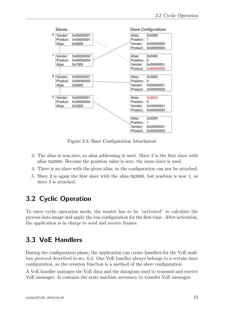
3.4 Concurrent Master Access
In some cases, one master is used by several instances, for example when an applicationdoes cyclic process data exchange, and there are EoE-capable slaves that require toexchange Ethernet data with the kernel (see sec. 6.1). For this reason, the master isa shared resource, and access to it has to be sequentialized. This is usually done bylocking with semaphores, or other methods to protect critical sections.
The master itself can not provide locking mechanisms, because it has no chance toknow the appropriate kind of lock. For example if the application is in kernelspaceand uses RTAI functionality, ordinary kernel semaphores would not be sufficient. Forthat, an important design decision was made: The application that reserved a mastermust have the total control, therefore it has to take responsibility for providing theappropriate locking mechanisms. If another instance wants to access the master, it hasto request the bus access via callbacks, that have to be provided by the application.Moreover the application can deny access to the master if it considers it to be awkwardat the moment.
Task
EoE
Master Module
Master0
Application Module
Applic
atio
n
Inte
rface
Figure 3.3: Concurrent Master Access
1If simultaneous sending and receiving is desired, two VoE handlers can be created for the slaveconfiguration.
14 6129a5f715fb, 2010/04/30
3.5 Distributed Clocks
Figure 3.3 exemplary shows, how two processes share one master: The application’scyclic task uses the master for process data exchange, while the master-internal EoEprocess uses it to communicate with EoE-capable slaves. Both have to access the busfrom time to time, but the EoE process does this by “asking” the application to dothe bus access for it. In this way, the application can use the appropriate lockingmechanism to avoid accessing the bus at the same time. See the application interfacedocumentation (chap. 3) for how to use these callbacks.
3.5 Distributed Clocks
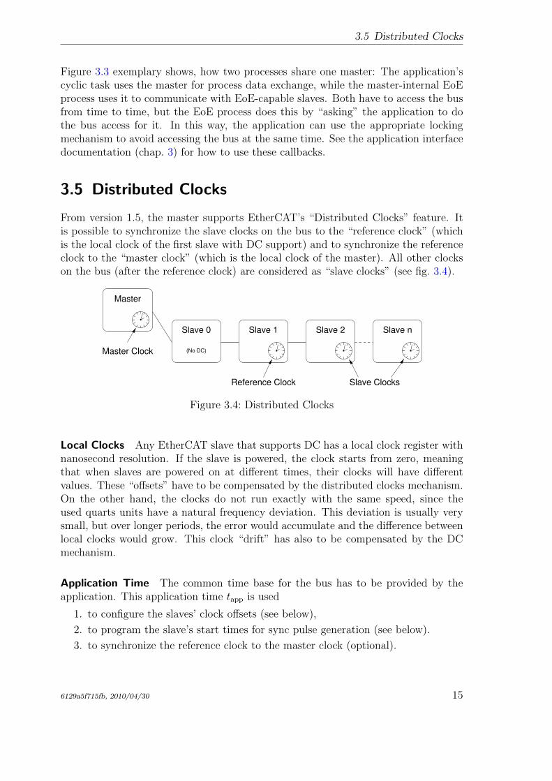
From version 1.5, the master supports EtherCAT’s “Distributed Clocks” feature. Itis possible to synchronize the slave clocks on the bus to the “reference clock” (whichis the local clock of the first slave with DC support) and to synchronize the referenceclock to the “master clock” (which is the local clock of the master). All other clockson the bus (after the reference clock) are considered as “slave clocks” (see fig. 3.4).
Reference Clock
Master Clock
Slave Clocks
Slave 2 Slave n
Master
Slave 1Slave 0
(No DC)
Figure 3.4: Distributed Clocks
Local Clocks Any EtherCAT slave that supports DC has a local clock register withnanosecond resolution. If the slave is powered, the clock starts from zero, meaningthat when slaves are powered on at different times, their clocks will have differentvalues. These “offsets” have to be compensated by the distributed clocks mechanism.On the other hand, the clocks do not run exactly with the same speed, since theused quarts units have a natural frequency deviation. This deviation is usually verysmall, but over longer periods, the error would accumulate and the difference betweenlocal clocks would grow. This clock “drift” has also to be compensated by the DCmechanism.
Application Time The common time base for the bus has to be provided by theapplication. This application time tapp is used
1. to configure the slaves’ clock offsets (see below),
2. to program the slave’s start times for sync pulse generation (see below).
3. to synchronize the reference clock to the master clock (optional).
6129a5f715fb, 2010/04/30 15
3 Application Interface
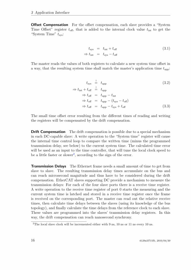
Offset Compensation For the offset compensation, each slave provides a “SystemTime Offset” register toff, that is added to the internal clock value tint to get the“System Time” tsys:
tsys = tint + toff (3.1)
⇒ tint = tsys − toff
The master reads the values of both registers to calculate a new system time offset ina way, that the resulting system time shall match the master’s application time tapp:
tsys!
= tapp (3.2)
⇒ tint + toff!
= tapp
⇒ toff = tapp − tint
⇒ toff = tapp − (tsys − toff)
⇒ toff = tapp − tsys + toff (3.3)
The small time offset error resulting from the different times of reading and writingthe registers will be compensated by the drift compensation.
Drift Compensation The drift compensation is possible due to a special mechanismin each DC-capable slave: A write operation to the “System time” register will causethe internal time control loop to compare the written time (minus the programmedtransmission delay, see below) to the current system time. The calculated time errorwill be used as an input to the time controller, that will tune the local clock speed tobe a little faster or slower2, according to the sign of the error.
Transmission Delays The Ethernet frame needs a small amount of time to get fromslave to slave. The resulting transmission delay times accumulate on the bus andcan reach microsecond magnitude and thus have to be considered during the driftcompensation. EtherCAT slaves supporting DC provide a mechanism to measure thetransmission delays: For each of the four slave ports there is a receive time register.A write operation to the receive time register of port 0 starts the measuring and thecurrent system time is latched and stored in a receive time register once the frameis received on the corresponding port. The master can read out the relative receivetimes, then calculate time delays between the slaves (using its knowledge of the bustopology), and finally calculate the time delays from the reference clock to each slave.These values are programmed into the slaves’ transmission delay registers. In thisway, the drift compensation can reach nanosecond synchrony.
2The local slave clock will be incremented either with 9 ns, 10 ns or 11 ns every 10 ns.
16 6129a5f715fb, 2010/04/30
3.5 Distributed Clocks
Checking Synchrony DC-capable slaves provide the 32-bit “System time difference”register at address 0x092c, where the system time difference of the last drift compensa-tion is stored in nanosecond resolution and in sign-and-magnitude coding3. To checkfor bus synchrony, the system time difference registers can also be cyclically read viathe command-line-tool (see sec. 7.1.14):
$ watch -n0 "ethercat reg read -p4 -tsm32 0x92c"
Sync Signals Synchronous clocks are only the prerequisite for synchronous eventson the bus. Each slave with DC support provides two “sync signals”, that can beprogrammed to create events, that will for example cause the slave application tolatch its inputs on a certain time. A sync event can either be generated once orcyclically, depending on what makes sense for the slave application. Programmingthe sync signals is a matter of setting the so-called “AssignActivate” word and thesync signals’ cycle- and shift times. The AssignActivate word is slave-specific and hasto be taken from the XML slave description (Device → Dc), where also typical syncsignal configurations “OpModes” can be found.
3This allows broadcast-reading all system time difference registers on the bus to get an upperapproximation
6129a5f715fb, 2010/04/30 17

3 Application Interface
18 6129a5f715fb, 2010/04/30
4 Ethernet Devices
The EtherCAT protocol is based on the Ethernet standard, so a master relies onstandard Ethernet hardware to communicate with the bus.
The term device is used as a synonym for Ethernet network interface hardware.
Native Ethernet Device Drivers There are native device driver modules (see sec. 4.2)that handle Ethernet hardware, which a master can use to connect to an EtherCATbus. They offer their Ethernet hardware to the master module via the device interface(see sec. 4.5) and must be capable to prepare Ethernet devices either for EtherCAT(realtime) operation or for “normal” operation using the kernel’s network stack. Theadvantage of this approach is that the master can operate nearly directly on the hard-ware, which allows a high performance. The disadvantage is, that there has to be anEtherCAT-capable version of the original Ethernet driver.
Generic Ethernet Device Driver From master version 1.5, there is a generic Ether-net device driver module (see sec. 4.3), that uses the lower layers of the network stackto connect to the hardware. The advantage is, that arbitrary Ethernet hardware canbe used for EtherCAT operation, independently of the actual hardware driver (so allLinux Ethernet drivers are supported without modifications). The disadvantage is,that this approach does not support realtime extensions like RTAI, because the Linuxnetwork stack is addressed. Moreover the performance is a little worse than the nativeapproach, because the Ethernet frame data have to traverse the network stack.
4.1 Network Driver Basics
EtherCAT relies on Ethernet hardware and the master needs a physical Ethernetdevice to communicate with the bus. Therefore it is necessary to understand howLinux handles network devices and their drivers, respectively.
Tasks of a Network Driver Network device drivers usually handle the lower twolayers of the OSI model, that is the physical layer and the data-link layer. A networkdevice itself natively handles the physical layer issues: It represents the hardware toconnect to the medium and to send and receive data in the way, the physical layerprotocol describes. The network device driver is responsible for getting data from the
6129a5f715fb, 2010/04/30 19
4 Ethernet Devices
kernel’s networking stack and forwarding it to the hardware, that does the physicaltransmission. If data is received by the hardware respectively, the driver is notified(usually by means of an interrupt) and has to read the data from the hardware memoryand forward it to the network stack. There are a few more tasks, a network devicedriver has to handle, including queue control, statistics and device dependent features.
Driver Startup Usually, a driver searches for compatible devices on module loading.For PCI drivers, this is done by scanning the PCI bus and checking for known deviceIDs. If a device is found, data structures are allocated and the device is taken intooperation.
Interrupt Operation A network device usually provides a hardware interrupt thatis used to notify the driver of received frames and success of transmission, or errors,respectively. The driver has to register an interrupt service routine (ISR), that isexecuted each time, the hardware signals such an event. If the interrupt was thrownby the own device (multiple devices can share one hardware interrupt), the reasonfor the interrupt has to be determined by reading the device’s interrupt register. Forexample, if the flag for received frames is set, frame data has to be copied fromhardware to kernel memory and passed to the network stack.
The net_device Structure The driver registers a net_device structure for eachdevice to communicate with the network stack and to create a “network interface”.In case of an Ethernet driver, this interface appears as ethX, where X is a numberassigned by the kernel on registration. The net_device structure receives events(either from userspace or from the network stack) via several callbacks, which haveto be set before registration. Not every callback is mandatory, but for reasonableoperation the ones below are needed in any case:
open() This function is called when network communication has to be started, for ex-ample after a command ip link set ethX up from userspace. Frame receptionhas to be enabled by the driver.
stop() The purpose of this callback is to “close” the device, i. e. make the hardwarestop receiving frames.
hard_start_xmit() This function is called for each frame that has to be transmitted.The network stack passes the frame as a pointer to an sk_buff structure (“socketbuffer”, see below), which has to be freed after sending.
get_stats() This call has to return a pointer to the device’s net_device_stats struc-ture, which permanently has to be filled with frame statistics. This means,that every time a frame is received, sent, or an error happened, the appropriatecounter in this structure has to be increased.
The actual registration is done with the register_netdev() call, unregistering is donewith unregister_netdev().
20 6129a5f715fb, 2010/04/30
4.2 Native EtherCAT Device Drivers
The netif Interface All other communication in the direction interface→ networkstack is done via the netif_*() calls. For example, on successful device opening,the network stack has to be notified, that it can now pass frames to the interface.This is done by calling netif_start_queue(). After this call, the hard_start_xmit()
callback can be called by the network stack. Furthermore a network driver usuallymanages a frame transmission queue. If this gets filled up, the network stack hasto be told to stop passing further frames for a while. This happens with a callto netif_stop_queue(). If some frames have been sent, and there is enough spaceagain to queue new frames, this can be notified with netif_wake_queue(). Anotherimportant call is netif_receive_skb()1: It passes a frame to the network stack, thatwas just received by the device. Frame data has to be included in a so-called “socketbuffer” for that (see below).
Socket Buffers Socket buffers are the basic data type for the whole network stack.They serve as containers for network data and are able to quickly add data headersand footers, or strip them off again. Therefore a socket buffer consists of an allocatedbuffer and several pointers that mark beginning of the buffer (head), beginning of data(data), end of data (tail) and end of buffer (end). In addition, a socket buffer holdsnetwork header information and (in case of received data) a pointer to the net_device,it was received on. There exist functions that create a socket buffer (dev_alloc_skb()),add data either from front (skb_push()) or back (skb_put()), remove data from front(skb_pull()) or back (skb_trim()), or delete the buffer (kfree_skb()). A socket bufferis passed from layer to layer, and is freed by the layer that uses it the last time. Incase of sending, freeing has to be done by the network driver.
4.2 Native EtherCAT Device Drivers
There are a few requirements, that applies to Ethernet hardware when used with anative Ethernet driver with EtherCAT functionality.
Dedicated Hardware For performance and realtime purposes, the EtherCAT masterneeds direct and exclusive access to the Ethernet hardware. This implies that thenetwork device must not be connected to the kernel’s network stack as usual, becausethe kernel would try to use it as an ordinary Ethernet device.
Interrupt-less Operation EtherCAT frames travel through the logical EtherCATring and are then sent back to the master. Communication is highly deterministic: Aframe is sent and will be received again after a constant time, so there is no need to
1This function is part of the NAPI (“New API”), that replaces the kernel 2.4 technique for in-terfacing to the network stack (with netif_rx()). NAPI is a technique to improve networkperformance on Linux. Read more in http://www.cyberus.ca/~hadi/usenix-paper.tgz.
6129a5f715fb, 2010/04/30 21
4 Ethernet Devices
notify the driver about frame reception: The master can instead query the hardwarefor received frames, if it expects them to be already received.
Figure 4.1 shows two workflows for cyclic frame transmission and reception with andwithout interrupts.
Interrupt
Tim
e
Frame Assembly
Frame Sending
ISR
Frame Dissection
Data Processing
Data Processing
...
...
Interrupt Operation
ISR
...
...
Data Processing
ISR
Frame Dissection
Frame Assembly
Frame Sending
Realtim
e C
ycle
Interrupt−less OperationR
ealtim
e C
ycle
Figure 4.1: Interrupt Operation versus Interrupt-less Operation
In the left workflow “Interrupt Operation”, the data from the last cycle is first pro-cessed and a new frame is assembled with new datagrams, which is then sent. Thecyclic work is done for now. Later, when the frame is received again by the hardware,an interrupt is triggered and the ISR is executed. The ISR will fetch the frame datafrom the hardware and initiate the frame dissection: The datagrams will be processed,so that the data is ready for processing in the next cycle.
In the right workflow “Interrupt-less Operation”, there is no hardware interrupt en-abled. Instead, the hardware will be polled by the master by executing the ISR. If theframe has been received in the meantime, it will be dissected. The situation is nowthe same as at the beginning of the left workflow: The received data is processed anda new frame is assembled and sent. There is nothing to do for the rest of the cycle.
The interrupt-less operation is desirable, because hardware interrupts are not con-ducive in improving the driver’s realtime behaviour: Their indeterministic incidencescontribute to increasing the jitter. Besides, if a realtime extension (like RTAI) is used,some additional effort would have to be made to prioritize interrupts.
Ethernet and EtherCAT Devices Another issue lies in the way Linux handles de-vices of the same type. For example, a PCI driver scans the PCI bus for devices it canhandle. Then it registers itself as the responsible driver for all of the devices found.The problem is, that an unmodified driver can not be told to ignore a device becauseit will be used for EtherCAT later. There must be a way to handle multiple devices
22 6129a5f715fb, 2010/04/30
4.3 Generic EtherCAT Device Driver
of the same type, where one is reserved for EtherCAT, while the other is treated asan ordinary Ethernet device.
For all this reasons, the author decided that the only acceptable solution is to modifystandard Ethernet drivers in a way that they keep their normal functionality, but gainthe ability to treat one or more of the devices as EtherCAT-capable.
Below are the advantages of this solution:
• No need to tell the standard drivers to ignore certain devices.
• One networking driver for EtherCAT and non-EtherCAT devices.
• No need to implement a network driver from scratch and running into issues,the former developers already solved.
The chosen approach has the following disadvantages:
• The modified driver gets more complicated, as it must handle EtherCAT andnon-EtherCAT devices.
• Many additional case differentiations in the driver code.
• Changes and bug fixes on the standard drivers have to be ported to the Ether-CAT-capable versions from time to time.
4.3 Generic EtherCAT Device Driver
Since there are approaches to enable the complete Linux kernel for realtime operation[11], it is possible to operate without native implementations of EtherCAT-capableEthernet device drivers and use the Linux network stack instead. Fig. 2.1 shows the“Generic Ethernet Driver Module”, that connects to local Ethernet devices via thenetwork stack. The kernel module is named ec_generic and can be loaded after themaster module like a native EtherCAT-capable Ethernet driver.
The generic device driver scans the network stack for interfaces, that have been reg-istered by Ethernet device drivers. It offers all possible devices to the EtherCATmaster. If the master accepts a device, the generic driver creates a packet socket (seeman 7 packet) with socket_type set to SOCK_RAW, bound to that device. All functionsof the device interface (see sec. 4.5) will then operate on that socket.
Below are the advantages of this solution:
• Any Ethernet hardware, that is covered by a Linux Ethernet driver can be usedfor EtherCAT.
• No modifications have to be made to the actual Ethernet drivers.
The generic approach has the following disadvantages:
• The performance is a little worse than the native approach, because the framedata have to traverse the lower layers of the network stack.
• It is not possible to use in-kernel realtime extensions like RTAI with the genericdriver, because the network stack code uses dynamic memory allocations andother things, that could cause the system to freeze in realtime context.
6129a5f715fb, 2010/04/30 23
4 Ethernet Devices
4.4 Providing Ethernet Devices
After loading the master module, additional module(s) have to be loaded to offerdevices to the master(s) (see sec. 4.5). The master module knows the devices tochoose from the module parameters (see sec. 2.1). If the init script is used to startthe master, the drivers and devices to use can be specified in the sysconfig file (seesec. 7.3.2).
Modules offering Ethernet devices can be
• native EtherCAT-capable network driver modules (see sec. 4.2) or
• the generic EtherCAT device driver module (see sec. 4.3).
4.5 EtherCAT Device Interface
An anticipation to the section about the master module (sec. 2.1) has to be made inorder to understand the way, a network device driver module can connect a device toa specific EtherCAT master.
The master module provides a “device interface” for network device drivers. To usethis interface, a network device driver module must include the header devices/ecdev.h,coming with the EtherCAT master code. This header offers a function interface forEtherCAT devices. All functions of the device interface are named with the prefixecdev.
The documentation of the device interface can be found in the header file or in theappropriate module of the interface documentation (see sec. 9.3 for generation in-structions).
4.6 Patching Native Network Drivers
This section will describe, how to make a standard Ethernet driver EtherCAT-capable,using the native approach (see sec. 4.2). Unfortunately, there is no standard procedureto enable an Ethernet driver for use with the EtherCAT master, but there are a fewcommon techniques.
1. A first simple rule is, that netif_*() calls must be avoided for all EtherCATdevices. As mentioned before, EtherCAT devices have no connection to thenetwork stack, and therefore must not call its interface functions.
2. Another important thing is, that EtherCAT devices should be operated withoutinterrupts. So any calls of registering interrupt handlers and enabling interruptsat hardware level must be avoided, too.
24 6129a5f715fb, 2010/04/30
4.6 Patching Native Network Drivers
3. The master does not use a new socket buffer for each send operation: In-stead there is a fix one allocated on master initialization. This socket bufferis filled with an EtherCAT frame with every send operation and passed to thehard_start_xmit() callback. For that it is necessary, that the socket buffer isnot be freed by the network driver as usual.
An Ethernet driver usually handles several Ethernet devices, each described by anet_device structure with a priv_data field to attach driver-dependent data to thestructure. To distinguish between normal Ethernet devices and the ones used byEtherCAT masters, the private data structure used by the driver could be extendedby a pointer, that points to an ec_device_t object returned by ecdev_offer() (seesec. 4.5) if the device is used by a master and otherwise is zero.
The RealTek RTL-8139 Fast Ethernet driver is a “simple” Ethernet driver and canbe taken as an example to patch new drivers. The interesting sections can be foundby searching the string “ecdev” in the file devices/8139too-2.6.24-ethercat.c.
6129a5f715fb, 2010/04/30 25

4 Ethernet Devices
26 6129a5f715fb, 2010/04/30
5 State Machines
Many parts of the EtherCAT master are implemented as finite state machines (FSMs).Though this leads to a higher grade of complexity in some aspects, is opens manynew possibilities.
The below short code example exemplary shows how to read all slave states andmoreover illustrates the restrictions of “sequential” coding:
1 ec_datagram_brd(datagram , 0x0130 , 2); // prepare datagram
2 if (ec_master_simple_io(master , datagram )) return -1;
3 slave_states = EC_READ_U8(datagram ->data); // process datagram
The ec master simple io() function provides a simple interface for synchronously send-ing a single datagram and receiving the result1. Internally, it queues the specifieddatagram, invokes the ec master send datagrams() function to send a frame with thequeued datagram and then waits actively for its reception.
This sequential approach is very simple, reflecting in only three lines of code. Thedisadvantage is, that the master is blocked for the time it waits for datagram reception.There is no difficulty when only one instance is using the master, but if more instanceswant to (synchronously2) use the master, it is inevitable to think about an alternativeto the sequential model.
Master access has to be sequentialized for more than one instance wanting to sendand receive datagrams synchronously. With the present approach, this would result inhaving one phase of active waiting for each instance, which would be non-acceptableespecially in realtime circumstances, because of the huge time overhead.
A possible solution is, that all instances would be executed sequentially to queuetheir datagrams, then give the control to the next instance instead of waiting for thedatagram reception. Finally, bus IO is done by a higher instance, which means thatall queued datagrams are sent and received. The next step is to execute all instancesagain, which then process their received datagrams and issue new ones.
This approach results in all instances having to retain their state, when giving thecontrol back to the higher instance. It is quite obvious to use a finite state machinemodel in this case. Section 5.1 will introduce some of the theory used, while the
1For all communication issues have been meanwhile sourced out into state machines, the functionis deprecated and stopped existing. Nevertheless it is adequate for showing it’s own restrictions.
2At this time, synchronous master access will be adequate to show the advantages of an FSM. Theasynchronous approach will be discussed in sec. 6.1
6129a5f715fb, 2010/04/30 27
5 State Machines
listings below show the basic approach by coding the example from above as a statemachine:
1 // state 1
2 ec_datagram_brd(datagram , 0x0130 , 2); // prepare datagram
3 ec_master_queue(master , datagram ); // queue datagram
4 next_state = state_2;
5 // state processing finished
After all instances executed their current state and queued their datagrams, these aresent and received. Then the respective next states are executed:
1 // state 2
2 if (datagram ->state != EC_DGRAM_STATE_RECEIVED) {
3 next_state = state_error;
4 return; // state processing finished
5 }
6 slave_states = EC_READ_U8(datagram ->data); // process datagram
7 // state processing finished.
See sec. 5.2 for an introduction to the state machine programming concept used inthe master code.
5.1 State Machine Theory
A finite state machine [8] is a model of behavior with inputs and outputs, where theoutputs not only depend on the inputs, but the history of inputs. The mathematicaldefinition of a finite state machine (or finite automaton) is a six-tuple (Σ,Γ, S, s0, δ, ω),with
• the input alphabet Σ, with Σ 6= ∅, containing all input symbols,
• the output alphabet Γ, with Γ 6= ∅, containing all output symbols,
• the set of states S, with S 6= ∅,• the set of initial states s0 with s0 ⊆ S, s0 6= ∅• the transition function δ : S × Σ→ S × Γ
• the output function ω.
The state transition function δ is often specified by a state transition table, or by astate transition diagram. The transition table offers a matrix view of the state machinebehavior (see table 5.1). The matrix rows correspond to the states (S = {s0, s1, s2})and the columns correspond to the input symbols (Γ = {a, b, ε}). The table contentsin a certain row i and column j then represent the next state (and possibly the output)for the case, that a certain input symbol σj is read in the state si.
28 6129a5f715fb, 2010/04/30
5.1 State Machine Theory
Table 5.1: A typical state transition table
a b εs0 s1 s1 s2
s1 s2 s1 s0
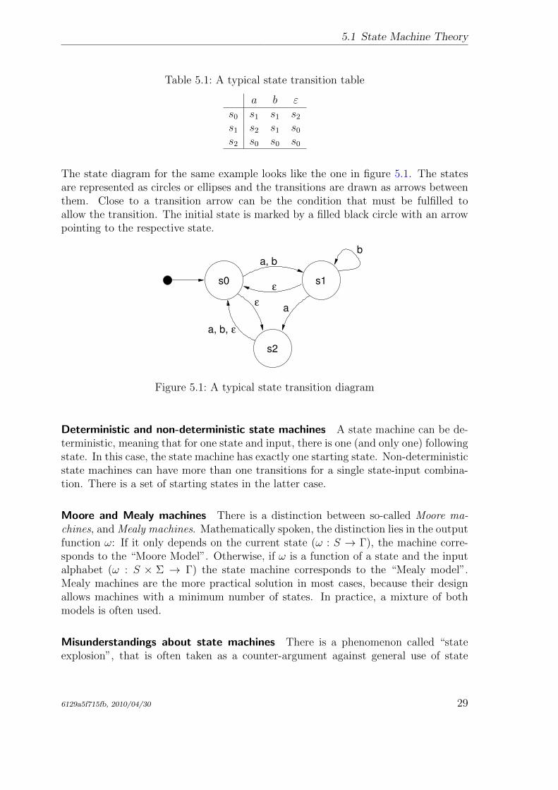
s2 s0 s0 s0
The state diagram for the same example looks like the one in figure 5.1. The statesare represented as circles or ellipses and the transitions are drawn as arrows betweenthem. Close to a transition arrow can be the condition that must be fulfilled toallow the transition. The initial state is marked by a filled black circle with an arrowpointing to the respective state.
s0 s1
s2
ε
ε
ε
a, b,
a
b
a, b
Figure 5.1: A typical state transition diagram
Deterministic and non-deterministic state machines A state machine can be de-terministic, meaning that for one state and input, there is one (and only one) followingstate. In this case, the state machine has exactly one starting state. Non-deterministicstate machines can have more than one transitions for a single state-input combina-tion. There is a set of starting states in the latter case.
Moore and Mealy machines There is a distinction between so-called Moore ma-chines, and Mealy machines. Mathematically spoken, the distinction lies in the outputfunction ω: If it only depends on the current state (ω : S → Γ), the machine corre-sponds to the “Moore Model”. Otherwise, if ω is a function of a state and the inputalphabet (ω : S × Σ → Γ) the state machine corresponds to the “Mealy model”.Mealy machines are the more practical solution in most cases, because their designallows machines with a minimum number of states. In practice, a mixture of bothmodels is often used.
Misunderstandings about state machines There is a phenomenon called “stateexplosion”, that is often taken as a counter-argument against general use of state
6129a5f715fb, 2010/04/30 29
5 State Machines
machines in complex environments. It has to be mentioned, that this point is mis-leading [9]. State explosions happen usually as a result of a bad state machine design:Common mistakes are storing the present values of all inputs in a state, or not divid-ing a complex state machine into simpler sub state machines. The EtherCAT masteruses several state machines, that are executed hierarchically and so serve as sub statemachines. These are also described below.
5.2 The Master’s State Model
This section will introduce the techniques used in the master to implement statemachines.
State Machine Programming There are certain ways to implement a state machinein C code. An obvious way is to implement the different states and actions by onebig case differentiation:
1 enum {STATE_1 , STATE_2 , STATE_3 };
2 int state = STATE_1;
3
4 void state_machine_run(void *priv_data) {
5 switch (state) {
6 case STATE_1:
7 action_1 ();
8 state = STATE_2;
9 break;
10 case STATE_2:
11 action_2 ()
12 if (some_condition) state = STATE_1;
13 else state = STATE_3;
14 break;
15 case STATE_3:
16 action_3 ();
17 state = STATE_1;
18 break;
19 }
20 }
For small state machines, this is an option. The disadvantage is, that with an increas-ing number of states the code soon gets complex and an additional case differentiationis executed each run. Besides, lots of indentation is wasted.
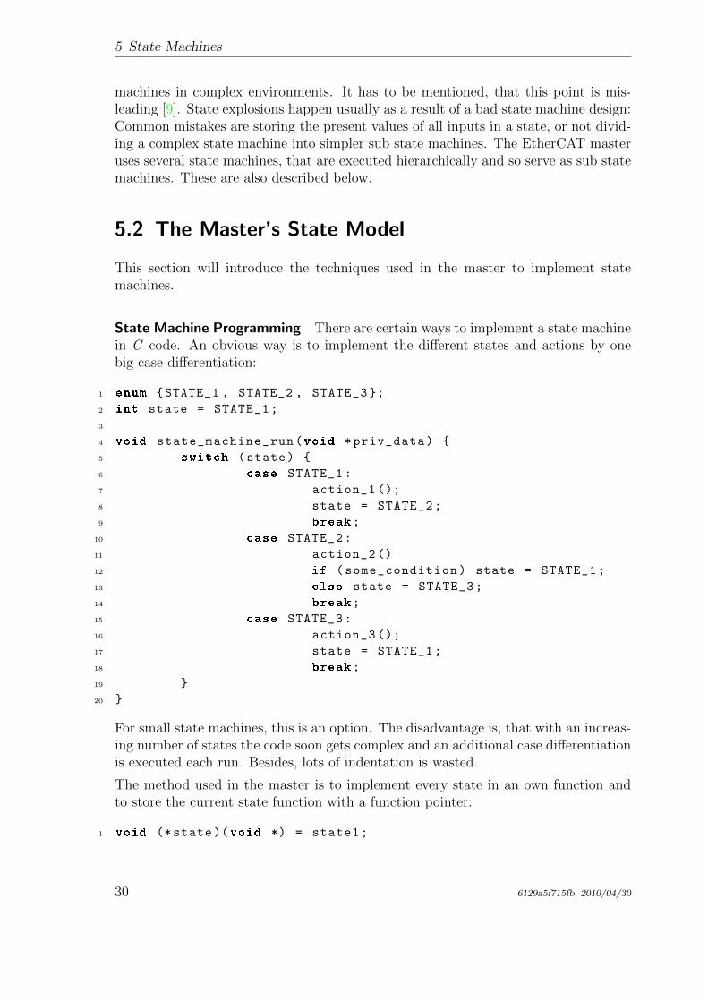
The method used in the master is to implement every state in an own function andto store the current state function with a function pointer:
1 void (* state)(void *) = state1;
30 6129a5f715fb, 2010/04/30
5.2 The Master’s State Model
2
3 void state_machine_run(void *priv_data) {
4 state(priv_data );
5 }
6
7 void state1(void *priv_data) {
8 action_1 ();
9 state = state2;
10 }
11
12 void state2(void *priv_data) {
13 action_2 ();
14 if (some_condition) state = state1;
15 else state = state2;
16 }
17
18 void state3(void *priv_data) {
19 action_3 ();
20 state = state1;
21 }
In the master code, state pointers of all state machines3 are gathered in a singleobject of the ec_fsm_master_t class. This is advantageous, because there is alwaysone instance of every state machine available and can be started on demand.
Mealy and Moore If a closer look is taken to the above listing, it can be seen thatthe actions executed (the “outputs” of the state machine) only depend on the currentstate. This accords to the “Moore” model introduced in sec. 5.1. As mentioned, the“Mealy” model offers a higher flexibility, which can be seen in the listing below:
1 void state7(void *priv_data) {
2 if (some_condition) {
3 action_7a ();
4 state = state1;
5 }
6 else {
7 action_7b ();
8 state = state8;
9 }
10 }
3© + 7© The state function executes the actions depending on the state transition,that is about to be done.
3All except for the EoE state machine, because multiple EoE slaves have to be handled in parallel.For this reason each EoE handler object has its own state pointer.
6129a5f715fb, 2010/04/30 31
5 State Machines
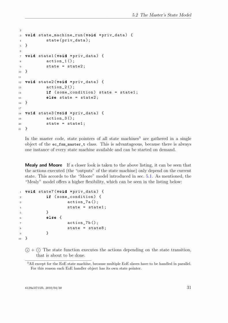
The most flexible alternative is to execute certain actions depending on the state,followed by some actions dependent on the state transition:
1 void state9(void *priv_data) {
2 action_9 ();
3 if (some_condition) {
4 action_9a ();
5 state = state7;
6 }
7 else {
8 action_9b ();
9 state = state10;
10 }
11 }
This model is often used in the master. It combines the best aspects of both ap-proaches.
Using Sub State Machines To avoid having too much states, certain functions ofthe EtherCAT master state machine have been sourced out into sub state machines.This helps to encapsulate the related workflows and moreover avoids the “state ex-plosion” phenomenon described in sec. 5.1. If the master would instead use one bigstate machine, the number of states would be a multiple of the actual number. Thiswould increase the level of complexity to a non-manageable grade.
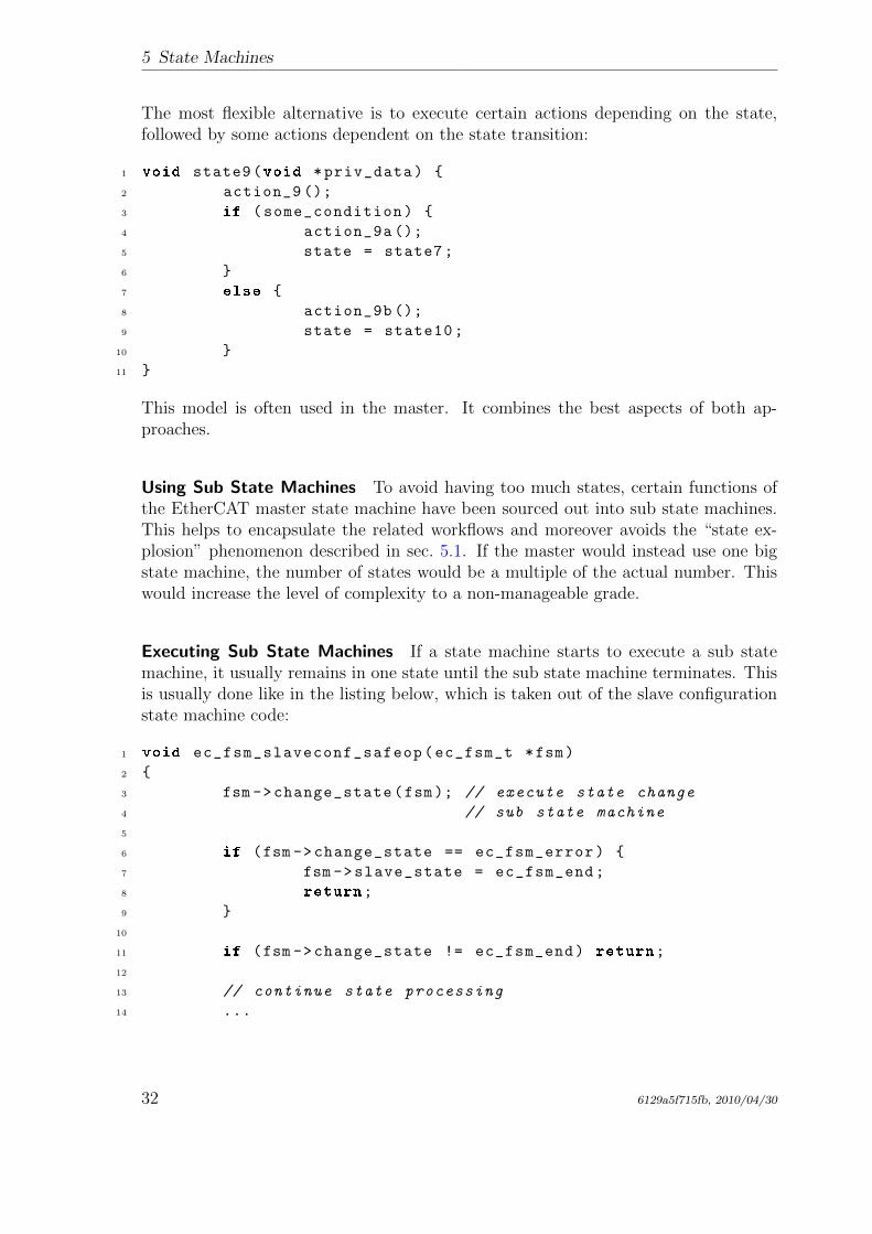
Executing Sub State Machines If a state machine starts to execute a sub statemachine, it usually remains in one state until the sub state machine terminates. Thisis usually done like in the listing below, which is taken out of the slave configurationstate machine code:
1 void ec_fsm_slaveconf_safeop(ec_fsm_t *fsm)
2 {
3 fsm ->change_state(fsm); // execute state change
4 // sub state machine
5
6 if (fsm ->change_state == ec_fsm_error) {
7 fsm ->slave_state = ec_fsm_end;
8 return;
9 }
10
11 if (fsm ->change_state != ec_fsm_end) return;
12
13 // continue state processing
14 ...
32 6129a5f715fb, 2010/04/30
5.3 The Master State Machine
3© change_state is the state pointer of the state change state machine. The statefunction, the pointer points on, is executed. . .
6© . . . either until the state machine terminates with the error state . . .
11© . . . or until the state machine terminates in the end state. Until then, the “higher”state machine remains in the current state and executes the sub state machineagain in the next cycle.
State Machine Descriptions The below sections describe every state machine usedin the EtherCAT master. The textual descriptions of the state machines containreferences to the transitions in the corresponding state transition diagrams, that aremarked with an arrow followed by the name of the successive state. Transitions causedby trivial error cases (i. e. no response from slave) are not described explicitly. Thesetransitions are drawn as dashed arrows in the diagrams.
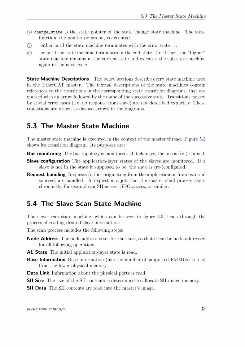
5.3 The Master State Machine
The master state machine is executed in the context of the master thread. Figure 5.2shows its transition diagram. Its purposes are:
Bus monitoring The bus topology is monitored. If it changes, the bus is (re-)scanned.
Slave configuration The application-layer states of the slaves are monitored. If aslave is not in the state it supposed to be, the slave is (re-)configured.
Request handling Requests (either originating from the application or from externalsources) are handled. A request is a job that the master shall process asyn-chronously, for example an SII access, SDO access, or similar.
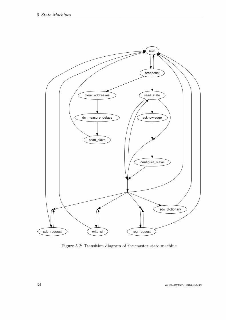
5.4 The Slave Scan State Machine
The slave scan state machine, which can be seen in figure 5.3, leads through theprocess of reading desired slave information.
The scan process includes the following steps:
Node Address The node address is set for the slave, so that it can be node-addressedfor all following operations.
AL State The initial application-layer state is read.
Base Information Base information (like the number of supported FMMUs) is readfrom the lower physical memory.
Data Link Information about the physical ports is read.
SII Size The size of the SII contents is determined to allocate SII image memory.
SII Data The SII contents are read into the master’s image.
6129a5f715fb, 2010/04/30 33
5 State Machines
start
broadcast
clear_addresses read_state
dc_measure_delays acknowledge
write_siisdo_request reg_request
sdo_dictionary
configure_slave
scan_slave
Figure 5.2: Transition diagram of the master state machine
34 6129a5f715fb, 2010/04/30
5.4 The Slave Scan State Machine
start
address
state
base
dc_capDC not
supported
datalink
sii_size
sii_data
end
No categorydata
preop
Not inPREOP
sync
pdos
Figure 5.3: Transition diagram of the slave scan state machine
6129a5f715fb, 2010/04/30 35
5 State Machines
PREOP If the slave supports CoE, it is set to PREOP state using the State changeFSM (see sec. 5.6) to enable mailbox communication and read the PDO config-uration via CoE.
PDOs The PDOs are read via CoE (if supported) using the PDO Reading FSM (seesec. 5.8). If this is successful, the PDO information from the SII (if any) isoverwritten.
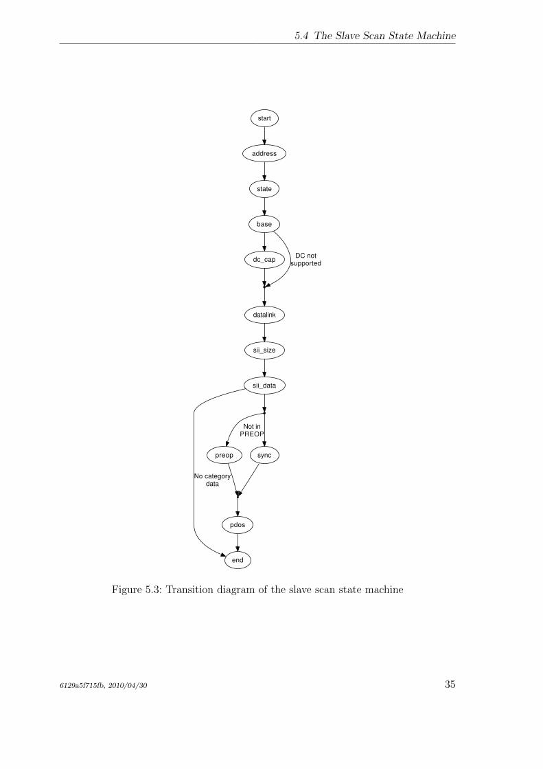
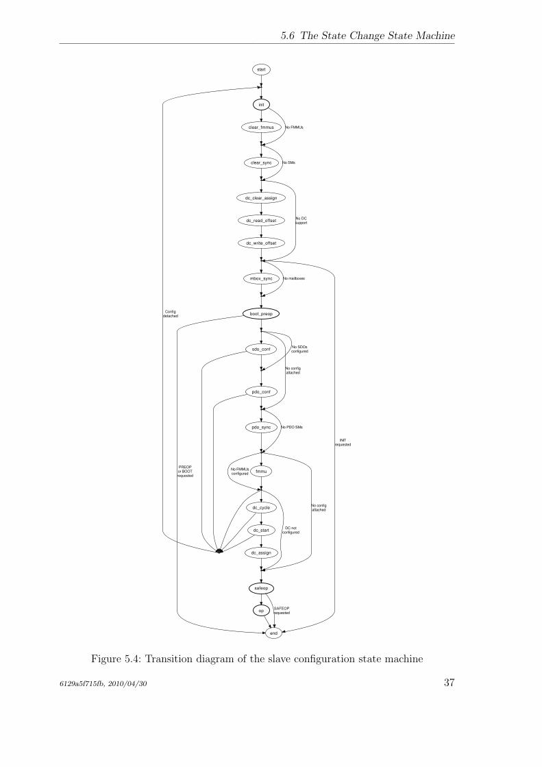
5.5 The Slave Configuration State Machine
The slave configuration state machine, which can be seen in figure 5.4, leads throughthe process of configuring a slave and bringing it to a certain application-layer state.
INIT The state change FSM is used to bring the slave to the INIT state.
FMMU Clearing To avoid that the slave reacts on any process data, the FMMUconfiguration are cleared. If the slave does not support FMMUs, this state isskipped. If INIT is the requested state, the state machine is finished.
Mailbox Sync Manager Configuration If the slaves support mailbox communica-tion, the mailbox sync managers are configured. Otherwise this state is skipped.
PREOP The state change FSM is used to bring the slave to PREOP state. If this isthe requested state, the state machine is finished.
SDO Configuration If there is a slave configuration attached (see sec. 3.1), and thereare any SDO configurations are provided by the application, these are sent tothe slave.
PDO Configuration The PDO configuration state machine is executed to apply allnecessary PDO configurations.
PDO Sync Manager Configuration If any PDO sync managers exist, they are con-figured.
FMMU Configuration If there are FMMUs configurations supplied by the applica-tion (i. e. if the application registered PDO entries), they are applied.
SAFEOP The state change FSM is used to bring the slave to SAFEOP state. If thisis the requested state, the state machine is finished.
OP The state change FSM is used to bring the slave to OP state. If this is therequested state, the state machine is finished.
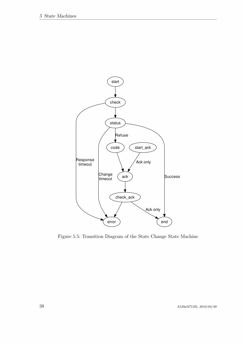
5.6 The State Change State Machine
The state change state machine, which can be seen in figure 5.5, leads through theprocess of changing a slave’s application-layer state. This implements the states andtransitions described in [3, sec. 6.4.1].
36 6129a5f715fb, 2010/04/30
5.6 The State Change State Machine
start
init
No FMMUsclear_fmmus
Configdetached
No SMsclear_sync
No DCsupport
dc_clear_assign
end
INITrequested
No mailboxesmbox_sync
dc_read_offset
dc_write_offset
boot_preop
PREOPor BOOTrequested
No configattached
No SDOsconfigured
sdo_conf
No PDO SMspdo_sync
pdo_conf
No configattached
No FMMUsconfigured
fmmu
safeop
DC notconfigured
dc_cycle
dc_start
dc_assign
SAFEOPrequested
op
Figure 5.4: Transition diagram of the slave configuration state machine
6129a5f715fb, 2010/04/30 37
5 State Machines
start
check
status
error
Responsetimeout
Changetimeout
end
Success
code
Refuse
ack
check_ack
start_ack
Ack only
Ack only
Figure 5.5: Transition Diagram of the State Change State Machine
38 6129a5f715fb, 2010/04/30
5.7 The SII State Machine
Start The new application-layer state is requested via the “AL Control Request”register (see [3, sec. 5.3.1]).
Check for Response Some slave need some time to respond to an AL state changecommand, and do not respond for some time. For this case, the command isissued again, until it is acknowledged.
Check AL Status If the AL State change datagram was acknowledged, the “AL Con-trol Response” register (see [3, sec. 5.3.2]) must be read out until the slavechanges the AL state.
AL Status Code If the slave refused the state change command, the reason can beread from the “AL Status Code” field in the “AL State Changed” registers(see [3, sec. 5.3.3]).
Acknowledge State If the state change was not successful, the master has to ac-knowledge the old state by writing to the “AL Control request” register again.
Check Acknowledge After sending the acknowledge command, it has to read out the“AL Control Response” register again.
The “start ack” state is a shortcut in the state machine for the case, that the masterwants to acknowledge a spontaneous AL state change, that was not requested.
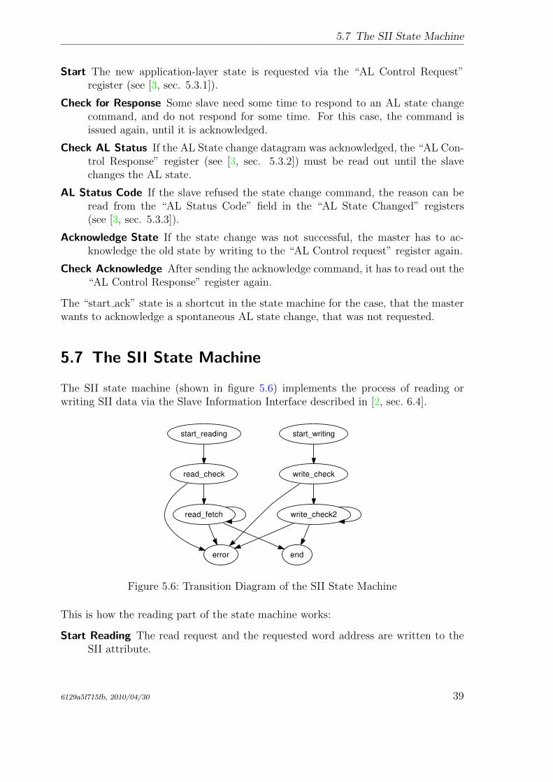
5.7 The SII State Machine
The SII state machine (shown in figure 5.6) implements the process of reading orwriting SII data via the Slave Information Interface described in [2, sec. 6.4].
start_reading
read_check
error
read_fetch
end
start_writing
write_check
write_check2
Figure 5.6: Transition Diagram of the SII State Machine
This is how the reading part of the state machine works:
Start Reading The read request and the requested word address are written to theSII attribute.
6129a5f715fb, 2010/04/30 39
5 State Machines
Check Read Command If the SII read request command has been acknowledged, atimer is started. A datagram is issued, that reads out the SII attribute for stateand data.
Fetch Data If the read operation is still busy (the SII is usually implemented as anE2PROM), the state is read again. Otherwise the data are copied from thedatagram.
The writing part works nearly similar:
Start Writing A write request, the target address and the data word are written tothe SII attribute.
Check Write Command If the SII write request command has been acknowledged,a timer is started. A datagram is issued, that reads out the SII attribute for thestate of the write operation.
Wait while Busy If the write operation is still busy (determined by a minimum waittime and the state of the busy flag), the state machine remains in this state toavoid that another write operation is issued too early.
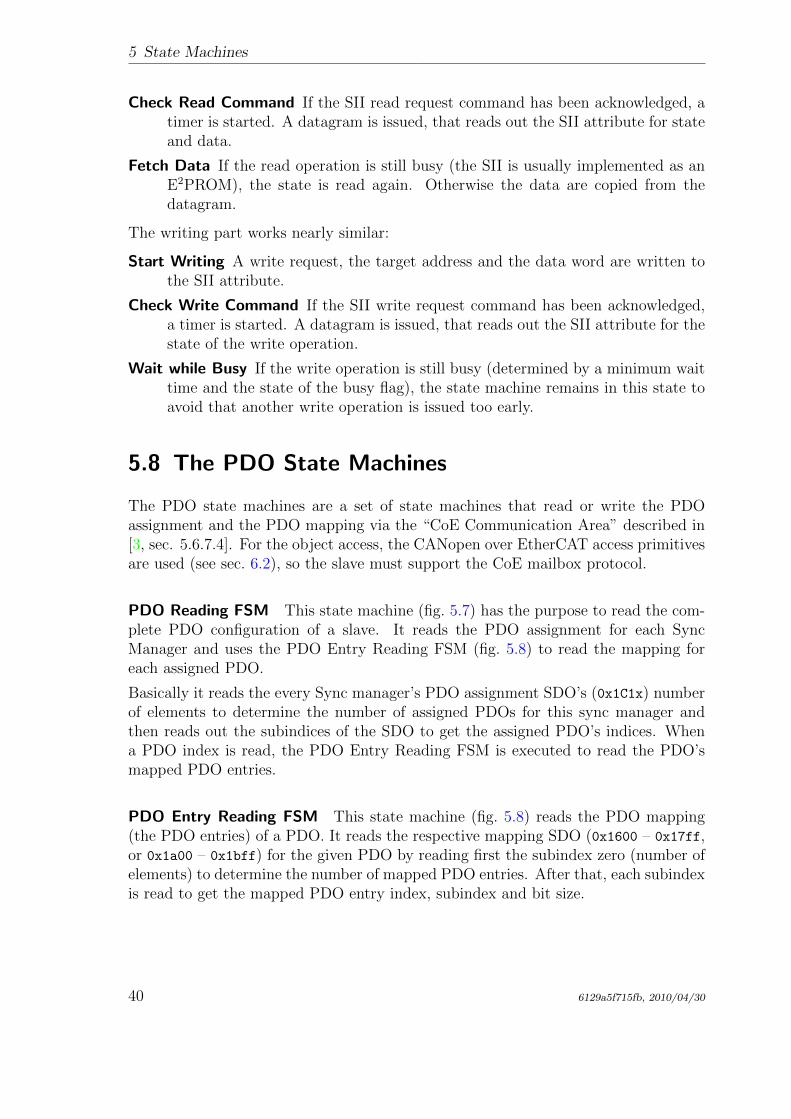
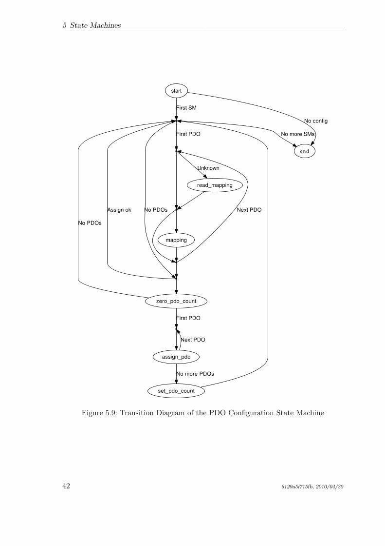
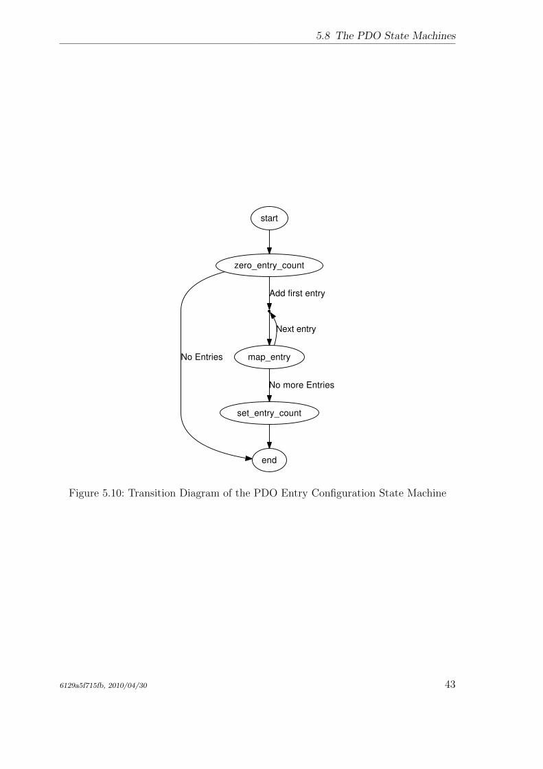
5.8 The PDO State Machines
The PDO state machines are a set of state machines that read or write the PDOassignment and the PDO mapping via the “CoE Communication Area” described in[3, sec. 5.6.7.4]. For the object access, the CANopen over EtherCAT access primitivesare used (see sec. 6.2), so the slave must support the CoE mailbox protocol.
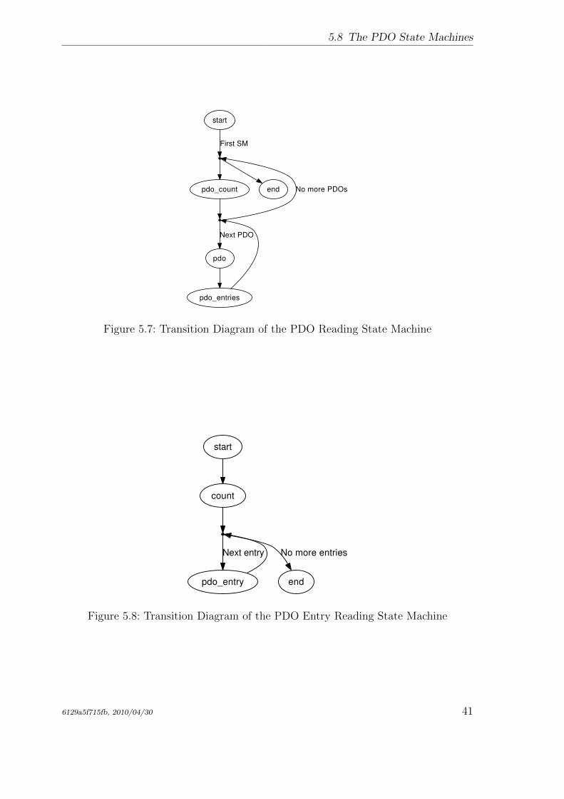
PDO Reading FSM This state machine (fig. 5.7) has the purpose to read the com-plete PDO configuration of a slave. It reads the PDO assignment for each SyncManager and uses the PDO Entry Reading FSM (fig. 5.8) to read the mapping foreach assigned PDO.
Basically it reads the every Sync manager’s PDO assignment SDO’s (0x1C1x) numberof elements to determine the number of assigned PDOs for this sync manager andthen reads out the subindices of the SDO to get the assigned PDO’s indices. Whena PDO index is read, the PDO Entry Reading FSM is executed to read the PDO’smapped PDO entries.
PDO Entry Reading FSM This state machine (fig. 5.8) reads the PDO mapping(the PDO entries) of a PDO. It reads the respective mapping SDO (0x1600 – 0x17ff,or 0x1a00 – 0x1bff) for the given PDO by reading first the subindex zero (number ofelements) to determine the number of mapped PDO entries. After that, each subindexis read to get the mapped PDO entry index, subindex and bit size.
40 6129a5f715fb, 2010/04/30
5.8 The PDO State Machines
start
First SM
pdo_count end No more PDOs
pdo
Next PDO
pdo_entries
Figure 5.7: Transition Diagram of the PDO Reading State Machine
start
count
pdo_entry
Next entry
end
No more entries
Figure 5.8: Transition Diagram of the PDO Entry Reading State Machine
6129a5f715fb, 2010/04/30 41
5 State Machines
start
First SM
end
No config
No more SMs
No PDOs
First PDO
Assign ok
zero_pdo_count
read_mapping
Unknown
mapping
Next PDO
No PDOs
First PDO
assign_pdo
Next PDO
set_pdo_count
No more PDOs
Figure 5.9: Transition Diagram of the PDO Configuration State Machine
42 6129a5f715fb, 2010/04/30
5.8 The PDO State Machines
start
zero_entry_count
end
No Entries
Add first entry
map_entry
Next entry
set_entry_count
No more Entries
Figure 5.10: Transition Diagram of the PDO Entry Configuration State Machine
6129a5f715fb, 2010/04/30 43

5 State Machines
44 6129a5f715fb, 2010/04/30
6 Mailbox Protocol Implementations
The EtherCAT master implements the CANopen over EtherCAT (CoE), Ethernetover EtherCAT (EoE), File-access over EtherCAT (FoE), Vendor-specific over Ether-CAT (VoE) and Servo Profile over EtherCAT (SoE) mailbox protocols. See the belowsections for details.
6.1 Ethernet over EtherCAT (EoE)
The EtherCAT master implements the Ethernet over EtherCAT mailbox protocol [3,sec. 5.7] to enable the tunneling of Ethernet frames to special slaves, that can eitherhave physical Ethernet ports to forward the frames to, or have an own IP stack toreceive the frames.
Virtual Network Interfaces The master creates a virtual EoE network interface forevery EoE-capable slave. These interfaces are called either
eoeXsY for a slave without an alias address (see sec. 7.1.2), where X is the masterindex and Y is the slave’s ring position, or
eoeXaY for a slave with a non-zero alias address, where X is the master index andY is the decimal alias address.
Frames sent to these interfaces are forwarded to the associated slaves by the master.Frames, that are received by the slaves, are fetched by the master and forwarded tothe virtual interfaces.
This bears the following advantages:
• Flexibility: The user can decide, how the EoE-capable slaves are interconnectedwith the rest of the world.
• Standard tools can be used to monitor the EoE activity and to configure theEoE interfaces.
• The Linux kernel’s layer-2-bridging implementation (according to the IEEE802.1D MAC Bridging standard) can be used natively to bridge Ethernet trafficbetween EoE-capable slaves.
• The Linux kernel’s network stack can be used to route packets between EoE-capable slaves and to track security issues, just like having physical networkinterfaces.
6129a5f715fb, 2010/04/30 45
6 Mailbox Protocol Implementations
EoE Handlers The virtual EoE interfaces and the related functionality is encap-sulated in the ec_eoe_t class. An object of this class is called “EoE handler”. Forexample the master does not create the network interfaces directly: This is done insidethe constructor of an EoE handler. An EoE handler additionally contains a framequeue. Each time, the kernel passes a new socket buffer for sending via the interface’shard_start_xmit() callback, the socket buffer is queued for transmission by the EoEstate machine (see below). If the queue gets filled up, the passing of new socket buffersis suspended with a call to netif_stop_queue().
Creation of EoE Handlers During bus scanning (see sec. 5.4), the master deter-mines the supported mailbox protocols foe each slave. This is done by examining the“Supported Mailbox Protocols” mask field at word address 0x001C of the SII. If bit1 is set, the slave supports the EoE protocol. In this case, an EoE handler is createdfor that slave.
EoE State Machine Every EoE handler owns an EoE state machine, that is usedto send frames to the corresponding slave and receive frames from the it via the EoEcommunication primitives. This state machine is showed in figure 6.1.
RX_START RX_CHECK RX_FETCH
TX_START TX_SENT
Figure 6.1: Transition Diagram of the EoE State Machine
RX START The beginning state of the EoE state machine. A mailbox check data-gram is sent, to query the slave’s mailbox for new frames. → RX CHECK
RX CHECK The mailbox check datagram is received. If the slave’s mailbox did notcontain data, a transmit cycle is started. → TX START
If there are new data in the mailbox, a datagram is sent to fetch the new data.→ RX FETCH
RX FETCH The fetch datagram is received. If the mailbox data do not containa “EoE Fragment request” command, the data are dropped and a transmitsequence is started. → TX START
If the received Ethernet frame fragment is the first fragment, a new socket bufferis allocated. In either case, the data are copied into the correct position of thesocket buffer.
46 6129a5f715fb, 2010/04/30
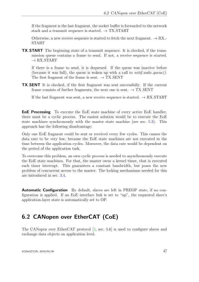
6.2 CANopen over EtherCAT (CoE)
If the fragment is the last fragment, the socket buffer is forwarded to the networkstack and a transmit sequence is started. → TX START
Otherwise, a new receive sequence is started to fetch the next fragment. → RX -START
TX START The beginning state of a transmit sequence. It is checked, if the trans-mission queue contains a frame to send. If not, a receive sequence is started.→ RX START
If there is a frame to send, it is dequeued. If the queue was inactive before(because it was full), the queue is woken up with a call to netif wake queue().The first fragment of the frame is sent. → TX SENT
TX SENT It is checked, if the first fragment was sent successfully. If the currentframe consists of further fragments, the next one is sent. → TX SENT
If the last fragment was sent, a new receive sequence is started. → RX START
EoE Processing To execute the EoE state machine of every active EoE handler,there must be a cyclic process. The easiest solution would be to execute the EoEstate machines synchronously with the master state machine (see sec. 5.3). Thisapproach has the following disadvantage:
Only one EoE fragment could be sent or received every few cycles. This causes thedata rate to be very low, because the EoE state machines are not executed in thetime between the application cycles. Moreover, the data rate would be dependent onthe period of the application task.
To overcome this problem, an own cyclic process is needed to asynchronously executethe EoE state machines. For that, the master owns a kernel timer, that is executedeach timer interrupt. This guarantees a constant bandwidth, but poses the newproblem of concurrent access to the master. The locking mechanisms needed for thisare introduced in sec. 3.4.
Automatic Configuration By default, slaves are left in PREOP state, if no con-figuration is applied. If an EoE interface link is set to “up”, the requested slave’sapplication-layer state is automatically set to OP.
6.2 CANopen over EtherCAT (CoE)
The CANopen over EtherCAT protocol [3, sec. 5.6] is used to configure slaves andexchange data objects on application level.
6129a5f715fb, 2010/04/30 47
6 Mailbox Protocol Implementations
SDO Download State Machine The best time to apply SDO configurations isduring the slave’s PREOP state, because mailbox communication is already possibleand slave’s application will start with updating input data in the succeeding SAFEOPstate. Therefore the SDO configuration has to be part of the slave configuration statemachine (see sec. 5.5): It is implemented via an SDO download state machine, that isexecuted just before entering the slave’s SAFEOP state. In this way, it is guaranteedthat the SDO configurations are applied each time, the slave is reconfigured.
The transition diagram of the SDO Download state machine can be seen in figure 6.2.
START REQUEST CHECK RESPONSE
ENDERROR
Figure 6.2: Transition diagram of the CoE download state machine
START The beginning state of the CoE download state machine. The “SDO Down-load Normal Request” mailbox command is sent. → REQUEST
REQUEST It is checked, if the CoE download request has been received by theslave. After that, a mailbox check command is issued and a timer is started.→ CHECK
CHECK If no mailbox data is available, the timer is checked.
• If it timed out, the SDO download is aborted. → ERROR
• Otherwise, the mailbox is queried again. → CHECK
If the mailbox contains new data, the response is fetched. → RESPONSE
RESPONSE If the mailbox response could not be fetched, the data is invalid, thewrong protocol was received, or a “Abort SDO Transfer Request” was received,the SDO download is aborted. → ERROR
If a “SDO Download Normal Response” acknowledgement was received, theSDO download was successful. → END
END The SDO download was successful.
ERROR The SDO download was aborted due to an error.
48 6129a5f715fb, 2010/04/30
6.3 Vendor specific over EtherCAT (VoE)
6.3 Vendor specific over EtherCAT (VoE)
The VoE protocol opens the possibility to implement a vendor-specific mailbox com-munication protocol. VoE mailbox messages are prepended by a VoE header con-taining a 32-bit vendor ID and a 16-bit vendor-type. There are no more constraintsregarding this protocol.
The EtherCAT master allows to create multiple VoE handlers per slave configurationvia the application interface (see chap. 3). These handlers contain the state machinenecessary for the communication via VoE.
For more information about using VoE handlers, see sec. 3.3 or the example applica-tions provided in the examples/ subdirectory.
6.4 Servo Profile over EtherCAT (SoE)
The SoE protocol implements the Service Channel layer, specified in IEC 61800-7 [15]via EtherCAT mailboxes.
The SoE protocol is quite similar to the CoE protocol (see sec. 6.2). Instead of SDOindices and subindices, so-called identification numbers (IDNs) identify parameters.
The implementation covers the “SCC Read” and “SCC Write” primitives, each withthe ability to fragment data.
There are several ways to use the SoE implementation:
• Reading and writing IDNs via the command-line tool (see sec. 7.1.18).
• Storing configurations for arbitrary IDNs via the application interface (see chap. 3,i. e. ecrt_slave_config_idn()). These configurations are written to the slaveduring configuration in PREOP state, before going to SAFEOP.
• The user-space library (see sec. 7.2), offers functions to read/write IDNs inblocking mode (ecrt_master_read_idn(), ecrt_master_write_idn()).
6129a5f715fb, 2010/04/30 49

6 Mailbox Protocol Implementations
50 6129a5f715fb, 2010/04/30
7 Userspace Interfaces
For the master runs as a kernel module, accessing it is natively limited to analyzingSyslog messages and controlling using modutils.
It was necessary to implement further interfaces, that make it easier to access themaster from userspace and allow a finer influence. It should be possible to view andto change special parameters at runtime.
Bus visualization is another point: For development and debugging purposes it isnecessary to show the connected slaves with a single command, for instance (seesec. 7.1).
The application interface has to be available in userspace, to allow userspace programsto use EtherCAT master functionality. This was implemented via a character deviceand a userspace library (see sec. 7.2).
Another aspect is automatic startup and configuration. The master must be able toautomatically start up with a persistent configuration (see sec. 7.3).
A last thing is monitoring EtherCAT communication. For debugging purposes, therehad to be a way to analyze EtherCAT datagrams. The best way would be witha popular network analyzer, like Wireshark [7] (the former Ethereal) or others (seesec. 7.4).
This chapter covers all these points and introduces the interfaces and tools to makeall that possible.
7.1 Command-line Tool
7.1.1 Character Devices
Each master instance will get a character device as a userspace interface. The devicesare named /dev/EtherCATx, where x ∈ {0 . . . n} is the index of the master.
Device Node Creation The character device nodes are automatically created, if theudev Package is installed. See sec. 9.5 for how to install and configure it.
6129a5f715fb, 2010/04/30 51
7 Userspace Interfaces
7.1.2 Setting Alias Addresses
ethercat alias [OPTIONS] <ALIAS >
Write alias addresses.
Arguments:
ALIAS must be an unsigned 16 bit number. Zero means
removing an alias address.
If multiple slaves are selected , the --force option
is required.
Command -specific options:
--alias -a <alias >
--position -p <pos > Slave selection. See the help of
the ’slaves ’ command.
--force -f Acknowledge writing aliases of
multiple slaves.
Numerical values can be specified either with decimal (no
prefix), octal (prefix ’0’) or hexadecimal (prefix ’0x’) base.
7.1.3 Displaying the Bus Configuration
ethercat config [OPTIONS]
Show slave configurations.
Without the --verbose option , slave configurations are
output one -per -line. Example:
1001:0 0x0000003b /0 x02010000 3 OP
| | | |
| | | \- Application -layer
| | | state of the attached
| | | slave , or ’-’, if no
| | | slave is attached.
| | \- Absolute decimal ring
| | position of the attached
| | slave , or ’-’ if none
| | attached.
| \- Expected vendor ID and product code (both
| hexadecimal ).
\- Alias address and relative position (both decimal ).
With the --verbose option given , the configured PDOs and
SDOs are output in addition.
Configuration selection:
Slave configurations can be selected with
52 6129a5f715fb, 2010/04/30
7.1 Command-line Tool
the --alias and --position parameters as follows:
1) If neither the --alias nor the --position option
is given , all slave configurations are displayed.
2) If only the --position option is given , an alias
of zero is assumed (see 4)).
3) If only the --alias option is given , all slave
configurations with the given alias address
are displayed.
4) If both the --alias and the --position option are
given , the selection can match a single
configuration , that is displayed , if it exists.
Command -specific options:
--alias -a <alias > Configuration alias (see above).
--position -p <pos > Relative position (see above).
--verbose -v Show detailed configurations.
Numerical values can be specified either with decimal (no
prefix), octal (prefix ’0’) or hexadecimal (prefix ’0x’) base.
7.1.4 Output PDO information in C Language
ethercat cstruct [OPTIONS]
Generate slave PDO information in C language.
The output C code can be used directly with the
ecrt_slave_config_pdos () function of the application
interface.
Command -specific options:
--alias -a <alias >
--position -p <pos > Slave selection. See the help of
the ’slaves ’ command.
Numerical values can be specified either with decimal (no
prefix), octal (prefix ’0’) or hexadecimal (prefix ’0x’) base.
7.1.5 Displaying Process Data
ethercat data [OPTIONS]
Output binary domain process data.
Data of multiple domains are concatenated.
Command -specific options:
--domain -d <index > Positive numerical domain index.
If omitted , data of all domains
are output.
6129a5f715fb, 2010/04/30 53
7 Userspace Interfaces
Numerical values can be specified either with decimal (no
prefix), octal (prefix ’0’) or hexadecimal (prefix ’0x’) base.
7.1.6 Setting a Master’s Debug Level
ethercat debug <LEVEL >
Set the master ’s debug level.
Debug messages are printed to syslog.
Arguments:
LEVEL can have one of the following values:
0 for no debugging output ,
1 for some debug messages , or
2 for printing all frame contents (use with caution !).
Numerical values can be specified either with decimal (no
prefix), octal (prefix ’0’) or hexadecimal (prefix ’0x’) base.
7.1.7 Configured Domains
ethercat domains [OPTIONS]
Show configured domains.
Without the --verbose option , the domains are displayed
one -per -line. Example:
Domain0: LogBaseAddr 0x00000000 , Size 6, WorkingCounter 0/1
The domain ’s base address for the logical datagram
(LRD/LWR/LRW) is displayed followed by the domain ’s
process data size in byte. The last values are the current
datagram working counter sum and the expected working
counter sum. If the values are equal , all PDOs were
exchanged during the last cycle.
If the --verbose option is given , the participating slave
configurations/FMMUs and the current process data are
additionally displayed:
Domain1: LogBaseAddr 0x00000006 , Size 6, WorkingCounter 0/1
SlaveConfig 1001:0 , SM3 ( Input), LogAddr 0x00000006 , Size 6
0x00 0x00 0x00 0x00 0x00 0x00
The process data are displayed as hexadecimal bytes.
Command -specific options:
--domain -d <index > Positive numerical domain index.
54 6129a5f715fb, 2010/04/30
7.1 Command-line Tool
If ommitted , all domains are
displayed.
--verbose -v Show FMMUs and process data
in addition.
Numerical values can be specified either with decimal (no
prefix), octal (prefix ’0’) or hexadecimal (prefix ’0x’) base.
7.1.8 SDO Access
ethercat download [OPTIONS] <INDEX > <SUBINDEX > <VALUE >
Write an SDO entry to a slave.
This command requires a single slave to be selected.
The data type of the SDO entry is taken from the SDO
dictionary by default. It can be overridden with the
--type option. If the slave does not support the SDO
information service or the SDO is not in the dictionary ,
the --type option is mandatory.
These are valid data types to use with
the --type option:
bool ,
int8 , int16 , int32 , int64 ,
uint8 , uint16 , uint32 , uint64 ,
float , double
string , octet_string , unicode_string.
For sign -and -magnitude coding , use the following types:
sm8 , sm16 , sm32 , sm64
Arguments:
INDEX is the SDO index and must be an unsigned
16 bit number.
SUBINDEX is the SDO entry subindex and must be an
unsigned 8 bit number.
VALUE is the value to download and must correspond
to the SDO entry datatype (see above).
Command -specific options:
--alias -a <alias >
--position -p <pos > Slave selection. See the help of
the ’slaves ’ command.
--type -t <type > SDO entry data type (see above).
Numerical values can be specified either with decimal (no
prefix), octal (prefix ’0’) or hexadecimal (prefix ’0x’) base.
ethercat upload [OPTIONS] <INDEX > <SUBINDEX >
6129a5f715fb, 2010/04/30 55
7 Userspace Interfaces
Read an SDO entry from a slave.
This command requires a single slave to be selected.
The data type of the SDO entry is taken from the SDO
dictionary by default. It can be overridden with the
--type option. If the slave does not support the SDO
information service or the SDO is not in the dictionary ,
the --type option is mandatory.
These are valid data types to use with
the --type option:
bool ,
int8 , int16 , int32 , int64 ,
uint8 , uint16 , uint32 , uint64 ,
float , double
string , octet_string , unicode_string.
For sign -and -magnitude coding , use the following types:
sm8 , sm16 , sm32 , sm64
Arguments:
INDEX is the SDO index and must be an unsigned
16 bit number.
SUBINDEX is the SDO entry subindex and must be an
unsigned 8 bit number.
Command -specific options:
--alias -a <alias >
--position -p <pos > Slave selection. See the help of
the ’slaves ’ command.
--type -t <type > SDO entry data type (see above).
Numerical values can be specified either with decimal (no
prefix), octal (prefix ’0’) or hexadecimal (prefix ’0x’) base.
7.1.9 EoE Statistics
ethercat eoe
Display Ethernet over EtherCAT statictics.
The TxRate and RxRate are displayed in Byte/s.
7.1.10 File-Access over EtherCAT
ethercat foe_read [OPTIONS] <SOURCEFILE >
Read a file from a slave via FoE.
This command requires a single slave to be selected.
56 6129a5f715fb, 2010/04/30
7.1 Command-line Tool
Arguments:
SOURCEFILE is the name of the source file on the slave.
Command -specific options:
--output -file -o <file > Local target filename. If
’-’ (default), data are
printed to stdout.
--alias -a <alias >
--position -p <pos > Slave selection. See the help
of the ’slaves ’ command.
Numerical values can be specified either with decimal (no
prefix), octal (prefix ’0’) or hexadecimal (prefix ’0x’) base.
ethercat foe_write [OPTIONS] <FILENAME >
Store a file on a slave via FoE.
This command requires a single slave to be selected.
Arguments:
FILENAME can either be a path to a file , or ’-’. In
the latter case , data are read from stdin and
the --output -file option has to be specified.
Command -specific options:
--output -file -o <file > Target filename on the slave.
If the FILENAME argument is
’-’, this is mandatory.
Otherwise , the basename () of
FILENAME is used by default.
--alias -a <alias >
--position -p <pos > Slave selection. See the help
of the ’slaves ’ command.
Numerical values can be specified either with decimal (no
prefix), octal (prefix ’0’) or hexadecimal (prefix ’0x’) base.
7.1.11 Creating Topology Graphs
ethercat graph [OPTIONS]
Output the bus topology as a graph.
The bus is output in DOT language (see
http :// www.graphviz.org/doc/info/lang.html), which can
be processed with the tools from the Graphviz
package. Example:
ethercat graph | dot -Tsvg > bus.svg
6129a5f715fb, 2010/04/30 57
7 Userspace Interfaces
See ’man dot ’ for more information.
7.1.12 Master and Ethernet Devices
ethercat master [OPTIONS]
Show master and Ethernet device information.
Command -specific options:
--master -m <indices > Master indices. A comma -separated
list with ranges is supported.
Example: 1,4,5,7-9. Default: - (all).
Numerical values can be specified either with decimal (no
prefix), octal (prefix ’0’) or hexadecimal (prefix ’0x’) base.
7.1.13 Sync Managers, PDOs and PDO Entries
ethercat pdos [OPTIONS]
List Sync managers , PDO assignment and mapping.
The information is displayed in three layers , which are
indented accordingly:
1) Sync managers - Contains the sync manager information
from the SII: Index , physical start address , default
size , control register and enable word. Example:
SM3: PhysAddr 0x1100 , DefaultSize 0, ControlRegister 0x20 , Enable 1
2) Assigned PDOs - PDO direction , hexadecimal index and
the PDO name , if avaliable. Note that a ’Tx ’ and ’Rx ’
are seen from the slave ’s point of view. Example:
TxPDO 0x1a00 "Channel1"
3) Mapped PDO entries - PDO entry index and subindex (both
hexadecimal), the length in bit and the description , if
available. Example:
PDO entry 0x3101:01, 8 bit , "Status"
Note , that the displayed PDO assignment and PDO mapping
information can either originate from the SII or from the
CoE communication area.
Command -specific options:
--alias -a <alias >
--position -p <pos > Slave selection. See the help of
58 6129a5f715fb, 2010/04/30
7.1 Command-line Tool
the ’slaves ’ command.
Numerical values can be specified either with decimal (no
prefix), octal (prefix ’0’) or hexadecimal (prefix ’0x’) base.
7.1.14 Register Access
ethercat reg_read [OPTIONS] <OFFSET > [LENGTH]
Output a slave ’s register contents.
This command requires a single slave to be selected.
Arguments:
OFFSET is the register address. Must
be an unsigned 16 bit number.
LENGTH is the number of bytes to read and must also be
an unsigned 16 bit number. OFFSET plus LENGTH
may not exceed 64k. The length is ignored (and
can be omitted), if a selected data type
implies a length.
These are valid data types to use with
the --type option:
bool ,
int8 , int16 , int32 , int64 ,
uint8 , uint16 , uint32 , uint64 ,
float , double
string , octet_string , unicode_string.
For sign -and -magnitude coding , use the following types:
sm8 , sm16 , sm32 , sm64
Command -specific options:
--alias -a <alias >
--position -p <pos > Slave selection. See the help of
the ’slaves ’ command.
--type -t <type > Data type (see above).
Numerical values can be specified either with decimal (no
prefix), octal (prefix ’0’) or hexadecimal (prefix ’0x’) base.
ethercat reg_write [OPTIONS] <OFFSET > <DATA >
Write data to a slave ’s registers.
This command requires a single slave to be selected.
Arguments:
OFFSET is the register address to write to.
DATA depends on whether a datatype was specified
with the --type option: If not , DATA must be
6129a5f715fb, 2010/04/30 59
7 Userspace Interfaces
either a path to a file with data to write ,
or ’-’, which means , that data are read from
stdin. If a datatype was specified , VALUE is
interpreted respective to the given type.
These are valid data types to use with
the --type option:
bool ,
int8 , int16 , int32 , int64 ,
uint8 , uint16 , uint32 , uint64 ,
float , double
string , octet_string , unicode_string.
For sign -and -magnitude coding , use the following types:
sm8 , sm16 , sm32 , sm64
Command -specific options:
--alias -a <alias >
--position -p <pos > Slave selection. See the help of
the ’slaves ’ command.
--type -t <type > Data type (see above).
Numerical values can be specified either with decimal (no
prefix), octal (prefix ’0’) or hexadecimal (prefix ’0x’) base.
7.1.15 SDO Dictionary
ethercat sdos [OPTIONS]
List SDO dictionaries.
SDO dictionary information is displayed in two layers ,
which are indented accordingly:
1) SDOs - Hexadecimal SDO index and the name. Example:
SDO 0x1018 , "Identity object"
2) SDO entries - SDO index and SDO entry subindex (both
hexadecimal) followed by the access rights (see
below), the data type , the length in bit , and the
description. Example:
0x1018 :01, rwrwrw , uint32 , 32 bit , "Vendor id"
The access rights are specified for the AL states PREOP ,
SAFEOP and OP. An ’r’ means , that the entry is readable
in the corresponding state , an ’w’ means writable ,
respectively. If a right is not granted , a dash ’-’ is
shown.
If the --quiet option is given , only the SDOs are output.
60 6129a5f715fb, 2010/04/30
7.1 Command-line Tool
Command -specific options:
--alias -a <alias >
--position -p <pos > Slave selection. See the help of
the ’slaves ’ command.
--quiet -q Only output SDOs (without the
SDO entries ).
Numerical values can be specified either with decimal (no
prefix), octal (prefix ’0’) or hexadecimal (prefix ’0x’) base.
7.1.16 SII Access
It is possible to directly read or write the complete SII contents of the slaves. Thiswas introduced for the reasons below:
• The format of the SII data is still in development and categories can be addedin the future. With read and write access, the complete memory contents canbe easily backed up and restored.
• Some SII data fields have to be altered (like the alias address). A quick writingmust be possible for that.
• Through reading access, analyzing category data is possible from userspace.
ethercat sii_read [OPTIONS]
Output a slave ’s SII contents.
This command requires a single slave to be selected.
Without the --verbose option , binary SII contents are
output.
With the --verbose option given , a textual representation
of the data is output , that is separated by SII category
names.
Command -specific options:
--alias -a <alias >
--position -p <pos > Slave selection. See the help of
the ’slaves ’ command.
--verbose -v Output textual data with
category names.
Numerical values can be specified either with decimal (no
prefix), octal (prefix ’0’) or hexadecimal (prefix ’0x’) base.
Reading out SII data is as easy as other commands. Though the data are in binaryformat, analysis is easier with a tool like hexdump:
$ ethercat sii read --position 3 | hexdump
0000000 0103 0000 0000 0000 0000 0000 0000 008c
6129a5f715fb, 2010/04/30 61
7 Userspace Interfaces
0000010 0002 0000 3052 07f0 0000 0000 0000 0000
0000020 0000 0000 0000 0000 0000 0000 0000 0000
...
Backing up SII contents can easily done with a redirection:
$ ethercat sii read --position 3 > sii-of-slave3.bin
To download SII contents to a slave, writing access to the master’s character deviceis necessary (see sec. 7.1.1).
ethercat sii_write [OPTIONS] <FILENAME >
Write SII contents to a slave.
This command requires a single slave to be selected.
The file contents are checked for validity and integrity.
These checks can be overridden with the --force option.
Arguments:
FILENAME must be a path to a file that contains a
positive number of words. If it is ’-’,
data are read from stdin.
Command -specific options:
--alias -a <alias >
--position -p <pos > Slave selection. See the help of
the ’slaves ’ command.
--force -f Override validity checks.
Numerical values can be specified either with decimal (no
prefix), octal (prefix ’0’) or hexadecimal (prefix ’0x’) base.
# ethercat sii write --position 3 sii-of-slave3.bin
The SII contents will be checked for validity and then sent to the slave. The writeoperation may take a few seconds.
7.1.17 Slaves on the Bus
Slave information can be gathered with the subcommand slaves:
ethercat slaves [OPTIONS]
Display slaves on the bus.
If the --verbose option is not given , the slaves are
displayed one -per -line. Example:
62 6129a5f715fb, 2010/04/30
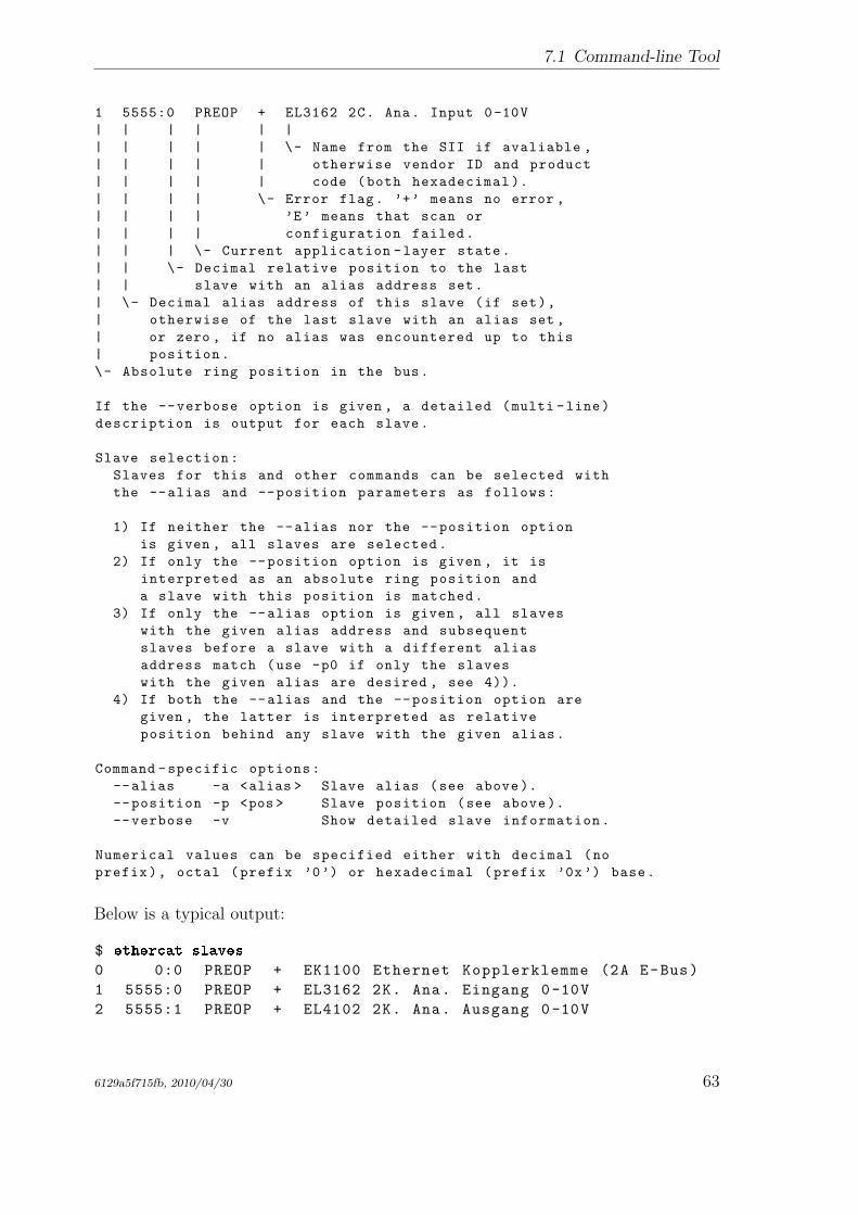
7.1 Command-line Tool
1 5555:0 PREOP + EL3162 2C. Ana. Input 0-10V
| | | | | |
| | | | | \- Name from the SII if avaliable ,
| | | | | otherwise vendor ID and product
| | | | | code (both hexadecimal ).
| | | | \- Error flag. ’+’ means no error ,
| | | | ’E’ means that scan or
| | | | configuration failed.
| | | \- Current application -layer state.
| | \- Decimal relative position to the last
| | slave with an alias address set.
| \- Decimal alias address of this slave (if set),
| otherwise of the last slave with an alias set ,
| or zero , if no alias was encountered up to this
| position.
\- Absolute ring position in the bus.
If the --verbose option is given , a detailed (multi -line)
description is output for each slave.
Slave selection:
Slaves for this and other commands can be selected with
the --alias and --position parameters as follows:
1) If neither the --alias nor the --position option
is given , all slaves are selected.
2) If only the --position option is given , it is
interpreted as an absolute ring position and
a slave with this position is matched.
3) If only the --alias option is given , all slaves
with the given alias address and subsequent
slaves before a slave with a different alias
address match (use -p0 if only the slaves
with the given alias are desired , see 4)).
4) If both the --alias and the --position option are
given , the latter is interpreted as relative
position behind any slave with the given alias.
Command -specific options:
--alias -a <alias > Slave alias (see above).
--position -p <pos > Slave position (see above).
--verbose -v Show detailed slave information.
Numerical values can be specified either with decimal (no
prefix), octal (prefix ’0’) or hexadecimal (prefix ’0x’) base.
Below is a typical output:
$ ethercat slaves
0 0:0 PREOP + EK1100 Ethernet Kopplerklemme (2A E-Bus)
1 5555:0 PREOP + EL3162 2K. Ana. Eingang 0-10V
2 5555:1 PREOP + EL4102 2K. Ana. Ausgang 0-10V
6129a5f715fb, 2010/04/30 63
7 Userspace Interfaces
3 5555:2 PREOP + EL2004 4K. Dig. Ausgang 24V, 0,5A
7.1.18 SoE IDN Access
ethercat soe_read [OPTIONS] <IDN >
Read an SoE IDN from a slave.
This command requires a single slave to be selected.
Arguments:
IDN is the IDN and must be either an unsigned
16 bit number acc. to IEC 61800 -7 -204:
Bit 15: (0) Standard data , (1) Product data
Bit 14 - 12: Parameter set (0 - 7)
Bit 11 - 0: Data block number
or a string like ’P-0-150’.
Data of the given IDN are read and displayed according to
the given datatype , or as raw hex bytes.
These are valid data types to use with
the --type option:
bool ,
int8 , int16 , int32 , int64 ,
uint8 , uint16 , uint32 , uint64 ,
float , double
string , octet_string , unicode_string.
For sign -and -magnitude coding , use the following types:
sm8 , sm16 , sm32 , sm64
Command -specific options:
--alias -a <alias >
--position -p <pos > Slave selection. See the help of
the ’slaves ’ command.
--type -t <type > Data type (see above).
Numerical values can be specified either with decimal (no
prefix), octal (prefix ’0’) or hexadecimal (prefix ’0x’) base.
ethercat soe_write [OPTIONS] <IDN > <VALUE >
Write an SoE IDN to a slave.
This command requires a single slave to be selected.
Arguments:
IDN is the IDN and must be either an unsigned
16 bit number acc. to IEC 61800 -7 -204:
Bit 15: (0) Standard data , (1) Product data
64 6129a5f715fb, 2010/04/30
7.1 Command-line Tool
Bit 14 - 12: Parameter set (0 - 7)
Bit 11 - 0: Data block number
or a string like ’P-0-150’.
VALUE is the value to write (see below ).
The VALUE argument is interpreted as the given data type
(--type is mandatory) and written to the selected slave.
These are valid data types to use with
the --type option:
bool ,
int8 , int16 , int32 , int64 ,
uint8 , uint16 , uint32 , uint64 ,
float , double
string , octet_string , unicode_string.
For sign -and -magnitude coding , use the following types:
sm8 , sm16 , sm32 , sm64
Command -specific options:
--alias -a <alias >
--position -p <pos > Slave selection. See the help of
the ’slaves ’ command.
--type -t <type > Data type (see above).
Numerical values can be specified either with decimal (no
prefix), octal (prefix ’0’) or hexadecimal (prefix ’0x’) base.
7.1.19 Requesting Application-Layer States
ethercat states [OPTIONS] <STATE >
Request application -layer states.
Arguments:
STATE can be ’INIT ’, ’PREOP ’, ’BOOT ’, ’SAFEOP ’, or ’OP ’.
Command -specific options:
--alias -a <alias >
--position -p <pos > Slave selection. See the help of
the ’slaves ’ command.
Numerical values can be specified either with decimal (no
prefix), octal (prefix ’0’) or hexadecimal (prefix ’0x’) base.
7.1.20 Displaying the Master Version
ethercat version [OPTIONS]
Show version information.
6129a5f715fb, 2010/04/30 65
7 Userspace Interfaces
7.1.21 Generating Slave Description XML
ethercat xml [OPTIONS]
Generate slave information XML.
Note that the PDO information can either originate
from the SII or from the CoE communication area. For
slaves , that support configuring PDO assignment and
mapping , the output depends on the last configuration.
Command -specific options:
--alias -a <alias >
--position -p <pos > Slave selection. See the help of
the ’slaves ’ command.
Numerical values can be specified either with decimal (no
prefix), octal (prefix ’0’) or hexadecimal (prefix ’0x’) base.
7.2 Userspace Library
The native application interface (see chap. 3) resides in kernelspace and hence isonly accessible from inside the kernel. To make the application interface availablefrom userspace programs, a userspace library has been created, that can be linked toprograms under the terms and conditions of the LGPL, version 2 [5].
The library is named libethercat. Its sources reside in the lib/ subdirectory and arebuild by default when using make. It is installed in the lib/ path below the installationprefix as libethercat.a (for static linking), libethercat.la (for the use with libtool) andlibethercat.so (for dynamic linking).
7.2.1 Using the Library
The application interface header ecrt.h can be used both in kernel and in user context.
The following minimal example shows how to build a program with EtherCAT func-tionality. An entire example can be found in the examples/user/ path of the mastersources.
#include <ecrt.h>
int main(void)
{
ec_master_t *master = ecrt_request_master (0);
if (! master)
return 1; // error
66 6129a5f715fb, 2010/04/30
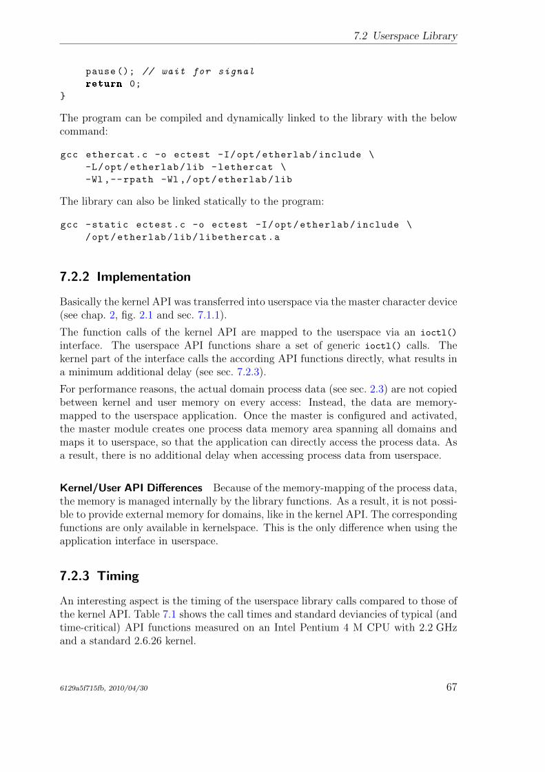
7.2 Userspace Library
pause (); // wait for signal
return 0;
}
The program can be compiled and dynamically linked to the library with the belowcommand:
gcc ethercat.c -o ectest -I/opt/etherlab/include \
-L/opt/etherlab/lib -lethercat \
-Wl ,--rpath -Wl ,/opt/etherlab/lib
The library can also be linked statically to the program:
gcc -static ectest.c -o ectest -I/opt/etherlab/include \
/opt/etherlab/lib/libethercat.a
7.2.2 Implementation
Basically the kernel API was transferred into userspace via the master character device(see chap. 2, fig. 2.1 and sec. 7.1.1).
The function calls of the kernel API are mapped to the userspace via an ioctl()
interface. The userspace API functions share a set of generic ioctl() calls. Thekernel part of the interface calls the according API functions directly, what results ina minimum additional delay (see sec. 7.2.3).
For performance reasons, the actual domain process data (see sec. 2.3) are not copiedbetween kernel and user memory on every access: Instead, the data are memory-mapped to the userspace application. Once the master is configured and activated,the master module creates one process data memory area spanning all domains andmaps it to userspace, so that the application can directly access the process data. Asa result, there is no additional delay when accessing process data from userspace.
Kernel/User API Differences Because of the memory-mapping of the process data,the memory is managed internally by the library functions. As a result, it is not possi-ble to provide external memory for domains, like in the kernel API. The correspondingfunctions are only available in kernelspace. This is the only difference when using theapplication interface in userspace.
7.2.3 Timing
An interesting aspect is the timing of the userspace library calls compared to those ofthe kernel API. Table 7.1 shows the call times and standard deviancies of typical (andtime-critical) API functions measured on an Intel Pentium 4 M CPU with 2.2 GHzand a standard 2.6.26 kernel.
6129a5f715fb, 2010/04/30 67
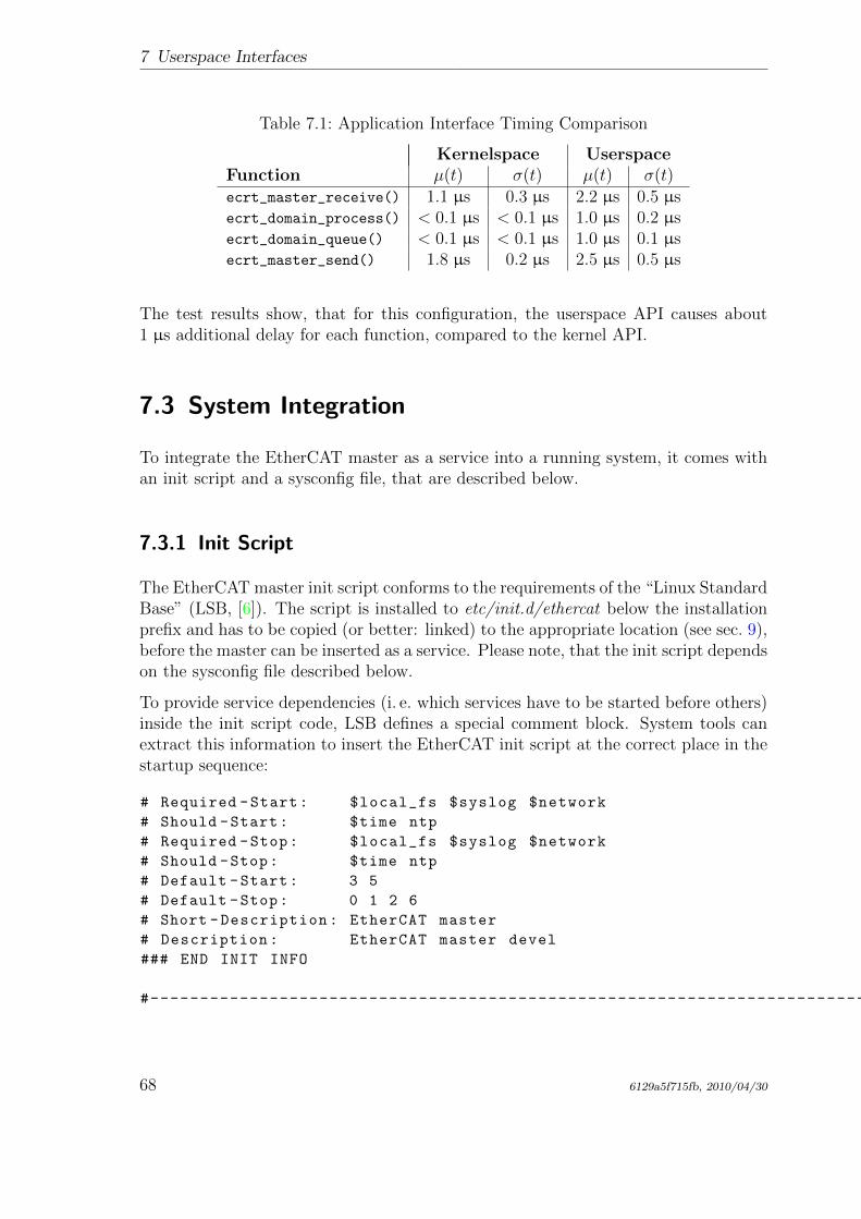
7 Userspace Interfaces
Table 7.1: Application Interface Timing Comparison
Kernelspace UserspaceFunction µ(t) σ(t) µ(t) σ(t)ecrt_master_receive() 1.1 µs 0.3 µs 2.2 µs 0.5 µsecrt_domain_process() < 0.1 µs < 0.1 µs 1.0 µs 0.2 µsecrt_domain_queue() < 0.1 µs < 0.1 µs 1.0 µs 0.1 µsecrt_master_send() 1.8 µs 0.2 µs 2.5 µs 0.5 µs
The test results show, that for this configuration, the userspace API causes about1 µs additional delay for each function, compared to the kernel API.
7.3 System Integration
To integrate the EtherCAT master as a service into a running system, it comes withan init script and a sysconfig file, that are described below.
7.3.1 Init Script
The EtherCAT master init script conforms to the requirements of the “Linux StandardBase” (LSB, [6]). The script is installed to etc/init.d/ethercat below the installationprefix and has to be copied (or better: linked) to the appropriate location (see sec. 9),before the master can be inserted as a service. Please note, that the init script dependson the sysconfig file described below.
To provide service dependencies (i. e. which services have to be started before others)inside the init script code, LSB defines a special comment block. System tools canextract this information to insert the EtherCAT init script at the correct place in thestartup sequence:
# Required -Start: $local_fs $syslog $network
# Should -Start: $time ntp
# Required -Stop: $local_fs $syslog $network
# Should -Stop: $time ntp
# Default -Start: 3 5
# Default -Stop: 0 1 2 6
# Short -Description: EtherCAT master
# Description: EtherCAT master devel
### END INIT INFO
#------------------------------------------------------------------------------
68 6129a5f715fb, 2010/04/30
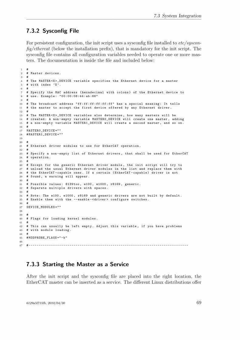
7.3 System Integration
7.3.2 Sysconfig File
For persistent configuration, the init script uses a sysconfig file installed to etc/syscon-fig/ethercat (below the installation prefix), that is mandatory for the init script. Thesysconfig file contains all configuration variables needed to operate one or more mas-ters. The documentation is inside the file and included below:
1 #
2 # Master devices.
3 #
4 # The MASTER <X>_DEVICE variable specifies the Ethernet device for a master
5 # with index ’X’.
6 #
7 # Specify the MAC address (hexadecimal with colons) of the Ethernet device to
8 # use. Example: "00:00:08:44: ab:66"
9 #
10 # The broadcast address "ff:ff:ff:ff:ff:ff" has a special meaning: It tells
11 # the master to accept the first device offered by any Ethernet driver.
12 #
13 # The MASTER <X>_DEVICE variables also determine , how many masters will be
14 # created: A non -empty variable MASTER0_DEVICE will create one master , adding
15 # a non -empty variable MASTER1_DEVICE will create a second master , and so on.
16 #
17 MASTER0_DEVICE =""
18 #MASTER1_DEVICE =""
19
20 #
21 # Ethernet driver modules to use for EtherCAT operation.
22 #
23 # Specify a non -empty list of Ethernet drivers , that shall be used for EtherCAT
24 # operation.
25 #
26 # Except for the generic Ethernet driver module , the init script will try to
27 # unload the usual Ethernet driver modules in the list and replace them with
28 # the EtherCAT -capable ones. If a certain (EtherCAT -capable) driver is not
29 # found , a warning will appear.
30 #
31 # Possible values: 8139too , e100 , e1000 , r8169 , generic.
32 # Separate multiple drivers with spaces.
33 #
34 # Note: The e100 , e1000 , r8169 and generic drivers are not built by default.
35 # Enable them with the --enable -<driver > configure switches.
36 #
37 DEVICE_MODULES =""
38
39 #
40 # Flags for loading kernel modules.
41 #
42 # This can usually be left empty. Adjust this variable , if you have problems
43 # with module loading.
44 #
45 #MODPROBE_FLAGS ="-b"
46
47 #------------------------------------------------------------------------------
7.3.3 Starting the Master as a Service
After the init script and the sysconfig file are placed into the right location, theEtherCAT master can be inserted as a service. The different Linux distributions offer
6129a5f715fb, 2010/04/30 69
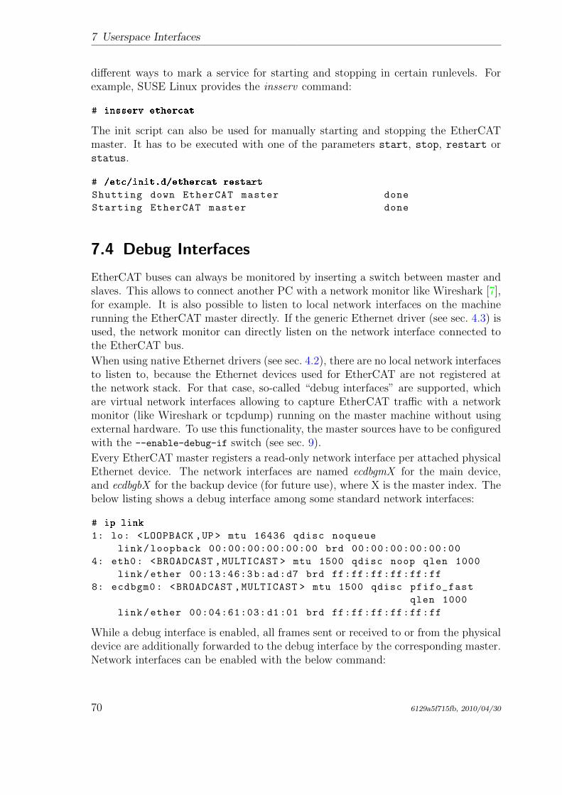
7 Userspace Interfaces
different ways to mark a service for starting and stopping in certain runlevels. Forexample, SUSE Linux provides the insserv command:
# insserv ethercat
The init script can also be used for manually starting and stopping the EtherCATmaster. It has to be executed with one of the parameters start, stop, restart orstatus.
# /etc/init.d/ethercat restart
Shutting down EtherCAT master done
Starting EtherCAT master done
7.4 Debug Interfaces
EtherCAT buses can always be monitored by inserting a switch between master andslaves. This allows to connect another PC with a network monitor like Wireshark [7],for example. It is also possible to listen to local network interfaces on the machinerunning the EtherCAT master directly. If the generic Ethernet driver (see sec. 4.3) isused, the network monitor can directly listen on the network interface connected tothe EtherCAT bus.
When using native Ethernet drivers (see sec. 4.2), there are no local network interfacesto listen to, because the Ethernet devices used for EtherCAT are not registered atthe network stack. For that case, so-called “debug interfaces” are supported, whichare virtual network interfaces allowing to capture EtherCAT traffic with a networkmonitor (like Wireshark or tcpdump) running on the master machine without usingexternal hardware. To use this functionality, the master sources have to be configuredwith the --enable-debug-if switch (see sec. 9).
Every EtherCAT master registers a read-only network interface per attached physicalEthernet device. The network interfaces are named ecdbgmX for the main device,and ecdbgbX for the backup device (for future use), where X is the master index. Thebelow listing shows a debug interface among some standard network interfaces:
# ip link
1: lo: <LOOPBACK ,UP > mtu 16436 qdisc noqueue
link/loopback 00:00:00:00:00:00 brd 00:00:00:00:00:00
4: eth0: <BROADCAST ,MULTICAST > mtu 1500 qdisc noop qlen 1000
link/ether 00:13:46:3b:ad:d7 brd ff:ff:ff:ff:ff:ff
8: ecdbgm0: <BROADCAST ,MULTICAST > mtu 1500 qdisc pfifo_fast
qlen 1000
link/ether 00:04:61:03: d1:01 brd ff:ff:ff:ff:ff:ff
While a debug interface is enabled, all frames sent or received to or from the physicaldevice are additionally forwarded to the debug interface by the corresponding master.Network interfaces can be enabled with the below command:
70 6129a5f715fb, 2010/04/30
7.4 Debug Interfaces
# ip link set dev ecdbgm0 up
Please note, that the frame rate can be very high. With an application connected,the debug interface can produce thousands of frames per second.
Attention The socket buffers needed for the operation of debug interfaces have tobe allocated dynamically. Some Linux realtime extensions (like RTAI) do not allowthis in realtime context!
6129a5f715fb, 2010/04/30 71

7 Userspace Interfaces
72 6129a5f715fb, 2010/04/30
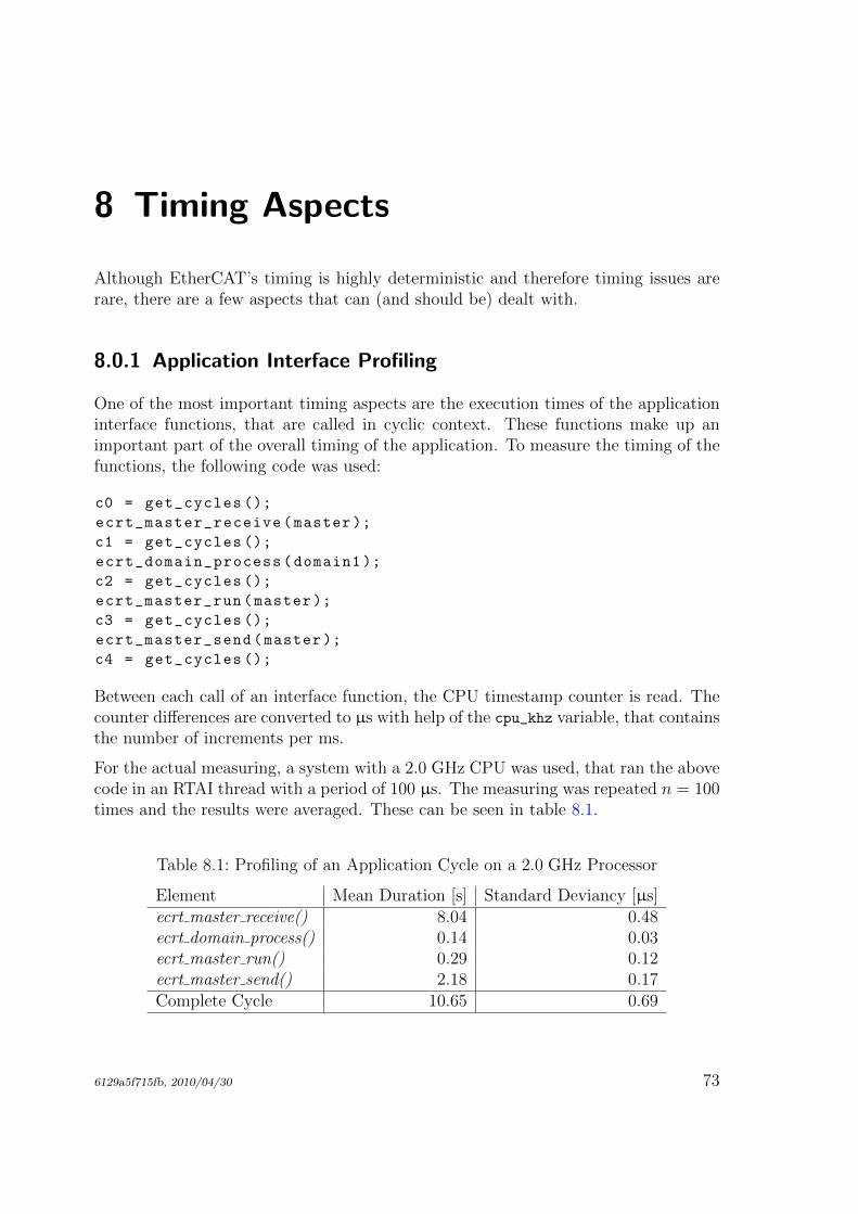
8 Timing Aspects
Although EtherCAT’s timing is highly deterministic and therefore timing issues arerare, there are a few aspects that can (and should be) dealt with.
8.0.1 Application Interface Profiling
One of the most important timing aspects are the execution times of the applicationinterface functions, that are called in cyclic context. These functions make up animportant part of the overall timing of the application. To measure the timing of thefunctions, the following code was used:
c0 = get_cycles ();
ecrt_master_receive(master );
c1 = get_cycles ();
ecrt_domain_process(domain1 );
c2 = get_cycles ();
ecrt_master_run(master );
c3 = get_cycles ();
ecrt_master_send(master );
c4 = get_cycles ();
Between each call of an interface function, the CPU timestamp counter is read. Thecounter differences are converted to µs with help of the cpu_khz variable, that containsthe number of increments per ms.
For the actual measuring, a system with a 2.0 GHz CPU was used, that ran the abovecode in an RTAI thread with a period of 100 µs. The measuring was repeated n = 100times and the results were averaged. These can be seen in table 8.1.
Table 8.1: Profiling of an Application Cycle on a 2.0 GHz Processor
Element Mean Duration [s] Standard Deviancy [µs]ecrt master receive() 8.04 0.48ecrt domain process() 0.14 0.03ecrt master run() 0.29 0.12ecrt master send() 2.18 0.17Complete Cycle 10.65 0.69
6129a5f715fb, 2010/04/30 73
8 Timing Aspects
It is obvious, that the functions accessing hardware make up the lion’s share. Theec master receive() executes the ISR of the Ethernet device, analyzes datagrams andcopies their contents into the memory of the datagram objects. The ec master send()assembles a frame out of different datagrams and copies it to the hardware buffers.Interestingly, this makes up only a quarter of the receiving time.
The functions that only operate on the masters internal data structures are veryfast (∆t < 1 µs). Interestingly the runtime of ec domain process() has a small stan-dard deviancy relative to the mean value, while this ratio is about twice as big forec master run(): This probably results from the latter function having to executecode depending on the current state and the different state functions are more or lesscomplex.
For a realtime cycle makes up about 10 µs, the theoretical frequency can be up to100 kHz. For two reasons, this frequency keeps being theoretical:
1. The processor must still be able to run the operating system between the real-time cycles.
2. The EtherCAT frame must be sent and received, before the next realtime cyclebegins. The determination of the bus cycle time is difficult and covered insec. 8.0.2.
8.0.2 Bus Cycle Measuring
For measuring the time, a frame is “on the wire”, two timestamps must be taken:
1. The time, the Ethernet hardware begins with physically sending the frame.
2. The time, the frame is completely received by the Ethernet hardware.
Both times are difficult to determine. The first reason is, that the interrupts aredisabled and the master is not notified, when a frame is sent or received (pollingwould distort the results). The second reason is, that even with interrupts enabled,the time from the event to the notification is unknown. Therefore the only way toconfidently determine the bus cycle time is an electrical measuring.
Anyway, the bus cycle time is an important factor when designing realtime code,because it limits the maximum frequency for the cyclic task of the application. Inpractice, these timing parameters are highly dependent on the hardware and often atrial and error method must be used to determine the limits of the system.
The central question is: What happens, if the cycle frequency is too high? The answeris, that the EtherCAT frames that have been sent at the end of the cycle are not yetreceived, when the next cycle starts. First this is noticed by ecrt domain process(),because the working counter of the process data datagrams were not increased. Thefunction will notify the user via Syslog1. In this case, the process data keeps being the
1To limit Syslog output, a mechanism has been implemented, that outputs a summarized notifica-tion at maximum once a second.
74 6129a5f715fb, 2010/04/30
same as in the last cycle, because it is not erased by the domain. When the domaindatagrams are queued again, the master notices, that they are already queued (andmarked as sent). The master will mark them as unsent again and output a warning,that datagrams were “skipped”.
On the mentioned 2.0 GHz system, the possible cycle frequency can be up to 25 kHzwithout skipped frames. This value can surely be increased by choosing faster hard-ware. Especially the RealTek network hardware could be replaced by a faster one.Besides, implementing a dedicated ISR for EtherCAT devices would also contributeto increasing the latency. These are two points on the author’s to-do list.
6129a5f715fb, 2010/04/30 75

8 Timing Aspects
76 6129a5f715fb, 2010/04/30
9 Installation
9.1 Getting the Software
There are several ways to get the master software:
1. An official release (for example 1.5.0), can be downloaded from the master’swebsite1 at the EtherLab project [1] as a tarball.
2. The most recent development revision (and moreover any other revision) canbe obtained via the Mercurial [13] repository on the master’s project page onSourceForge.net2. The whole repository can be cloned with the command
hg clone http :// etherlabmaster.hg.sourceforge.net/hgweb/
etherlabmaster/etherlabmaster local-dir
3. Without a local Mercurial installation, tarballs of arbitrary revisions can bedownloaded via the “bz2” links in the browsable repository pages3.
9.2 Building the Software
After downloading a tarball or cloning the repository as described in sec. 9.1, thesources have to be prepared and configured for the build process.
When a tarball was downloaded, it has to be extracted with the following commands:
$ tar xjf ethercat-1.5.0.tar.bz2
$ cd ethercat-1.5.0/
The software configuration is managed with Autoconf [14] so the released versionscontain a configure shell script, that has to be executed for configuration (see below).
Bootstrap When downloading or cloning directly from the repository, the configure
script does not yet exist. It can be created via the bootstrap.sh script in the mastersources. The autoconf and automake packages are required for this.
1http://etherlab.org/en/ethercat/index.php2http://sourceforge.net/projects/etherlabmaster3http://etherlabmaster.hg.sourceforge.net/hgweb/etherlabmaster/etherlabmaster
6129a5f715fb, 2010/04/30 77
9 Installation
Configuration and Build The configuration and the build process follow the belowcommands:
$ ./configure
$ make
$ make modules
Table 9.1 lists important configuration switches and options.
9.3 Building the Interface Documentation
The source code is documented using Doxygen [12]. To build the HTML documen-tation, the Doxygen software has to be installed. The below command will generatethe documents in the subdirectory doxygen-output :
$ make doc
The interface documentation can be viewed by pointing a browser to the file doxygen-output/html/index.html. The functions and data structures of the application interfacea covered by an own module “Application Interface”.
9.4 Installing the Software
The below commands have to be entered as root : The first one will install the Ether-CAT header, init script, sysconfig file and the userspace tool to the prefix path. Thesecond one will install the kernel modules to the kernel’s modules directory. The finaldepmod call is necessary to include the kernel modules into the modules.dep file tomake it available to the modprobe command, used in the init script.
# make install
# make modules install
# depmod
If the target kernel’s modules directory is not under /lib/modules, a different destina-tion directory can be specified with the DESTDIR make variable. For example:
# make DESTDIR=/vol/nfs/root modules install
This command will install the compiled kernel modules to /vol/nfs/root/lib/modules,prepended by the kernel release.
If the EtherCAT master shall be run as a service4 (see sec. 7.3), the init script and thesysconfig file have to be copied (or linked) to the appropriate locations. The belowexample is suitable for SUSE Linux. It may vary for other distributions.
4Even if the EtherCAT master shall not be loaded on system startup, the use of the init script isrecommended for manual (un-)loading.
78 6129a5f715fb, 2010/04/30
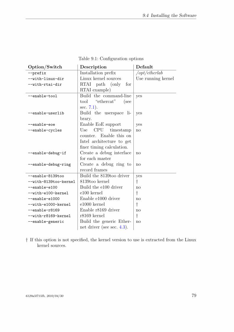
9.4 Installing the Software
Table 9.1: Configuration options
Option/Switch Description Default--prefix Installation prefix /opt/etherlab--with-linux-dir Linux kernel sources Use running kernel--with-rtai-dir RTAI path (only for
RTAI example)--enable-tool Build the command-line
tool “ethercat” (seesec. 7.1).
yes
--enable-userlib Build the userspace li-brary.
yes
--enable-eoe Enable EoE support yes--enable-cycles Use CPU timestamp
counter. Enable this onIntel architecture to getfiner timing calculation.
no
--enable-debug-if Create a debug interfacefor each master
no
--enable-debug-ring Create a debug ring torecord frames
no
--enable-8139too Build the 8139too driver yes--with-8139too-kernel 8139too kernel †--enable-e100 Build the e100 driver no--with-e100-kernel e100 kernel †--enable-e1000 Enable e1000 driver no--with-e1000-kernel e1000 kernel †--enable-r8169 Enable r8169 driver no--with-r8169-kernel r8169 kernel †--enable-generic Build the generic Ether-
net driver (see sec. 4.3).no
† If this option is not specified, the kernel version to use is extracted from the Linuxkernel sources.
6129a5f715fb, 2010/04/30 79
9 Installation
# cd /opt/etherlab
# cp etc/sysconfig/ethercat /etc/sysconfig/
# ln -s etc/init.d/ethercat /etc/init.d/
# insserv ethercat
Now the sysconfig file /etc/sysconfig/ethercat (see sec. 7.3.2) has to be cus-tomized. The minimal customization is to set the MASTER0_DEVICE variable to theMAC address of the Ethernet device to use (or ff:ff:ff:ff:ff:ff to use the firstdevice offered) and selecting the driver(s) to load via the DEVICE_MODULES variable.
After the basic configuration is done, the master can be started with the below com-mand:
# /etc/init.d/ethercat start
At this time, the operation of the master can be observed by viewing the Syslogmessages, which should look like the ones below. If EtherCAT slaves are connectedto the master’s EtherCAT device, the activity indicators should begin to flash.
1 EtherCAT: Master driver 1.5.0
2 EtherCAT: 1 master waiting for devices.
3 EtherCAT Intel(R) PRO /1000 Network Driver - version 6.0.60 -k2
4 Copyright (c) 1999 -2005 Intel Corporation.
5 PCI: Found IRQ 12 for device 0000:01:01.0
6 PCI: Sharing IRQ 12 with 0000:00:1d.2
7 PCI: Sharing IRQ 12 with 0000:00:1f.1
8 EtherCAT: Accepting device 00:0E:0C:DA:A2:20 for master 0.
9 EtherCAT: Starting master thread.
10 ec_e1000: ec0: e1000_probe: Intel(R) PRO /1000 Network
11 Connection
12 ec_e1000: ec0: e1000_watchdog_task: NIC Link is Up 100 Mbps
13 Full Duplex
14 EtherCAT: Link state changed to UP.
15 EtherCAT: 7 slave(s) responding.
16 EtherCAT: Slave states: PREOP.
17 EtherCAT: Scanning bus.
18 EtherCAT: Bus scanning completed in 431 ms.
1© – 2© The master module is loading, and one master is initialized.
3© – 8© The EtherCAT-capable e1000 driver is loading. The master accepts the de-vice with the address 00:0E:0C:DA:A2:20.
9© – 16© The master goes to idle phase, starts its state machine and begins scanningthe bus.
80 6129a5f715fb, 2010/04/30
9.5 Automatic Device Node Creation
9.5 Automatic Device Node Creation
The ethercat command-line tool (see sec. 7.1) communicates with the master via acharacter device. The corresponding device nodes are created automatically, if theudev daemon is running. Note, that on some distributions, the udev package is notinstalled by default.
The device nodes will be created with mode 0660 and group root by default. If “nor-mal” users shall have reading access, a udev rule file (for example /etc/udev/rules.d/99-EtherCAT.rules) has to be created with the following contents:
KERNEL ==" EtherCAT [0-9]*", MODE ="0664"
After the udev rule file is created and the EtherCAT master is restarted with /etc
/init.d/ethercat restart, the device node will be automatically created with thedesired rights:
# ls -l /dev/EtherCAT0
crw -rw -r-- 1 root root 252, 0 2008 -09 -03 16:19 /dev/EtherCAT0
Now, the ethercat tool can be used (see sec. 7.1) even as a non-root user.
If non-root users shall have writing access, the following udev rule can be used instead:
KERNEL ==" EtherCAT [0-9]*", MODE ="0664" , GROUP=" users"
6129a5f715fb, 2010/04/30 81

9 Installation
82 6129a5f715fb, 2010/04/30
Bibliography
[1] Ingenieurgemeinschaft IgH: EtherLab – Open Source Toolkit for rapid realtimecode generation under Linux with Simulink/RTW and EtherCAT technology.http://etherlab.org/en, 2008.
[2] IEC 61158-4-12: Data-link Protocol Specification. International ElectrotechnicalCommission (IEC), 2005.
[3] IEC 61158-6-12: Application Layer Protocol Specification. International Elec-trotechnical Commission (IEC), 2005.
[4] GNU General Public License, Version 2. http://www.gnu.org/licenses/
gpl-2.0.html. October 15, 2008.
[5] GNU Lesser General Public License, Version 2.1. http://www.gnu.org/
licenses/old-licenses/lgpl-2.1.html. October 15, 2008.
[6] Linux Standard Base. http://www.linuxfoundation.org/en/LSB. August 9,2006.
[7] Wireshark. http://www.wireshark.org. 2008.
[8] Hopcroft, J. E. / Ullman, J. D.: Introduction to Automata Theory, Languagesand Computation. Adison-Wesley, Reading, Mass. 1979.
[9] Wagner, F. / Wolstenholme, P.: State machine misunderstandings. In: IEEjournal “Computing and Control Engineering”, 2004.
[10] RTAI. The RealTime Application Interface for Linux from DIAPM. https://www.rtai.org, 2010.
[11] RT PREEMPT HOWTO. http://rt.wiki.kernel.org/index.php/RT_
PREEMPT_HOWTO, 2010.
[12] Doxygen. Source code documentation generator tool. http://www.stack.nl/
~dimitri/doxygen, 2008.
[13] Mercurial SCM. http://mercurial.selenic.com, 2010.
[14] Autoconf – GNU Project – Free Software Foundation (FSF). http://www.gnu.org/software/autoconf, 2010.
[15] IEC 61800-7-304: Adjustable speed electrical power drive systems - Part 7-300:Generic interface and use of profiles for power drive systems - Mapping of profilesto network technologies. International Electrotechnical Commission (IEC), 2007.
6129a5f715fb, 2010/04/30 83