Embed Size (px)
Citation preview

Specification Test MethodsASTM D6890/EN 15195 (IP498)
Ignition Quality g o Qua yTester (IQT™)
Technology UpdateTechnology Update
Fuel Rating SymposiumOctober, 2010

WelcomeWelcome
• I would like to thank you for taking time out ofI would like to thank you for taking time out of your busy schedules to come to attend presentation ‐ in particular to hear thispresentation in particular to hear this D6890/EN 15195 (IP 498) progress review updateupdate

Presentation TopicsPresentation Topics
• IQT™ History• Test Method Development at EI and ASTM• Use of the IQT™ from a global perspective
Th i ifi f th IQT™ i bi di l f l d l t• The significance of the IQT™ in biodiesel fuel development and commercialization
• The effective use of the IQT™ with cetane improver (2‐ethy hexyl nitrate ‐2EHN and ditertiary butyl peroxide ‐DTB)
• The effective use of the IQT™ in refinery diesel fuel blending optimization (establish blend values for components)opt at o (estab s b e d a ues o co po e ts)
• Regulatory use of the IQT™ for regular and premium diesel fuel
Presentation Topics Cont’d.Presentation Topics Cont d.
• Development of a high precision MDV Fuel Injection Pump that will further improve precision
• Precision Update Status ( ASTM & EI Exchange Group Data)• Update on Refinery On Line Model (ROLM) IQT™• Update on Refinery On‐Line Model (ROLM) IQT• Preliminary Test Results for New Reference Fuel Blends• Durability track record and recent durability improvements• Update on near Totally Automated Laboratory Model (TALM)
IQT™• Ease of Maintenance• Ease of Maintenance• Expansion of test method scope above 64 DCN and below 33
DCN

Presentation Topics Cont’d.Presentation Topics Cont d.
• Combined use of primary reference fuels with heptane and p y pmethylcyclohexane (MCH) to improve ease of calibration
• Summary

IQT™ HistoryIQT History
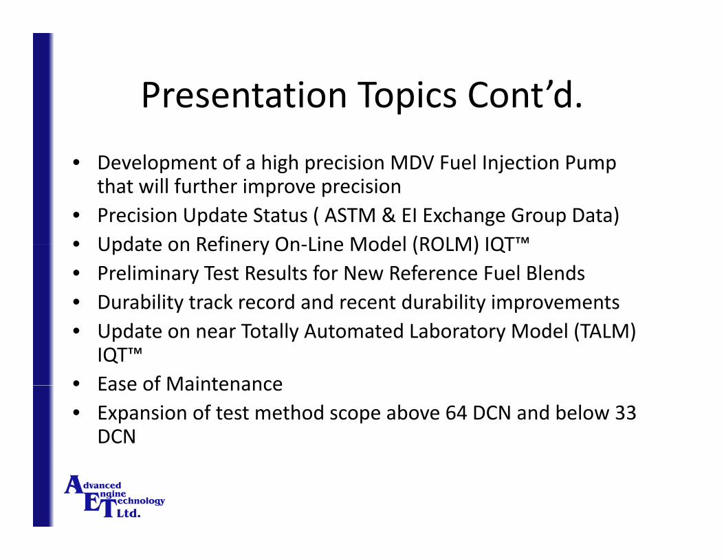
• The IQT™ was initially developed as a hand operatedThe IQT was initially developed as a hand operated research tool by Southwest Research Institute (SwRI) in San Antonio, Texas
• AET acquired the technology from SwRI in 1994
IQT™ History Cont’d.IQT History Cont d.
SwRI’s hand‐operated research CVCC deviceSwRI s hand operated research CVCC device

IQT™ History Cont’d.IQT History Cont d.
• Considerable effort was required to determine theConsiderable effort was required to determine the major sources of error in order to further develop the instrument
• The main R&D focus was targeted towards developing a robust/optimized ignition delaydeveloping a robust/optimized ignition delay measurement algorithm that was based on a large data base of ASTM – NEG fuel remnants

IQT™ History Cont’d.IQT History Cont d.
SwRI hand‐operated research CVCC device in operation (c.1993)

IQT™ History Cont’d.
• The second main R&D focus was automating the
IQT History Cont d.
The second main R&D focus was automating the instrument’s sequence of injection and combustion events.
IQT™ History Cont’d.IQT History Cont d.
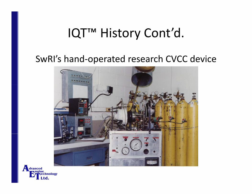
SwRI/AET’s development of a first prototype IQT™, manufactured by SwRI

IQT™ History Cont’d.IQT History Cont d.
Prototype IQT™’s combustion chamber and injection pumpyp Q j p p
Handle for inlet valve
Injection release mechanism
Pneumatic piston
Handle for
mechanism
exhaust valve

IQT™ History Cont’d.IQT History Cont d.
Updated prototype IQT™ under test at AETp p yp Q
Solenoid actuator
Pneumatically actuated valves
Data acquisition and control computer

Test Method Development at EI and ASTM
• The first test method was written in accordance withThe first test method was written in accordance with the Energy Institute (EI) format and was first approved by EI as IP 498
• The EI version was then utilized to commence the ASTM version and approved in 2002 as D6890ASTM version and approved in 2002 as D6890
Test Method Development at EI and ’dASTM Cont’d.
• AET continues to be grateful for the knowledgeableAET continues to be grateful for the knowledgeable help of John Jones with this initial ASTM test method
B th t t th d d l d i t t ll• Both test methods were developed in a totally open and transparent manner
Test Method Development at EI and ’dASTM Cont’d.
• Throughout the test method development the IQTTMThroughout the test method development the IQTInstrument User Group (UG) played a major role in test method development and round robin testing
• The IQTTM UG met by teleconference call every two weeks for several years – these teleconference callsweeks for several years these teleconference calls were kindly hosted by BP Oil
Test Method Development at EI and ’dASTM Cont’d.
• More recently, the UG helped with the IndependentMore recently, the UG helped with the Independent Laboratory Study (ILS) for B100 materials and their use in D6751
• AET and the UG has supplied test data for the development of ASTM D7467 – Fuel Specification fordevelopment of ASTM D7467 Fuel Specification for B6 to B20

Test Method Development at EI and ’dASTM Cont’d.
• AET has planned additional testing of B100 for D613AET has planned additional testing of B100 for D613 and D6890 by UG and AET (on two B100 feedstocksthat meet D6751)
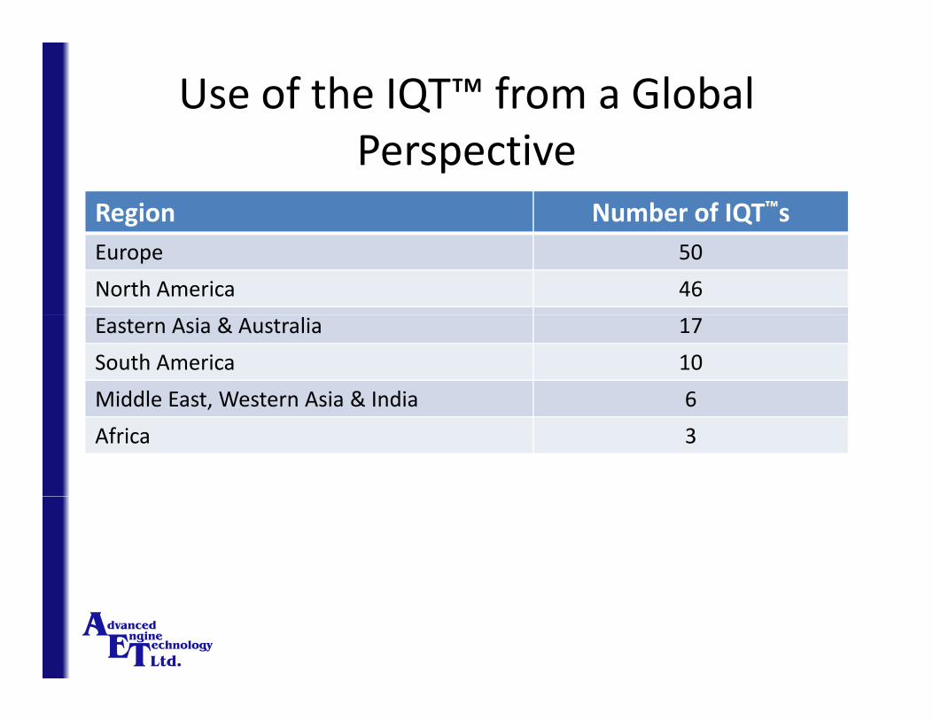
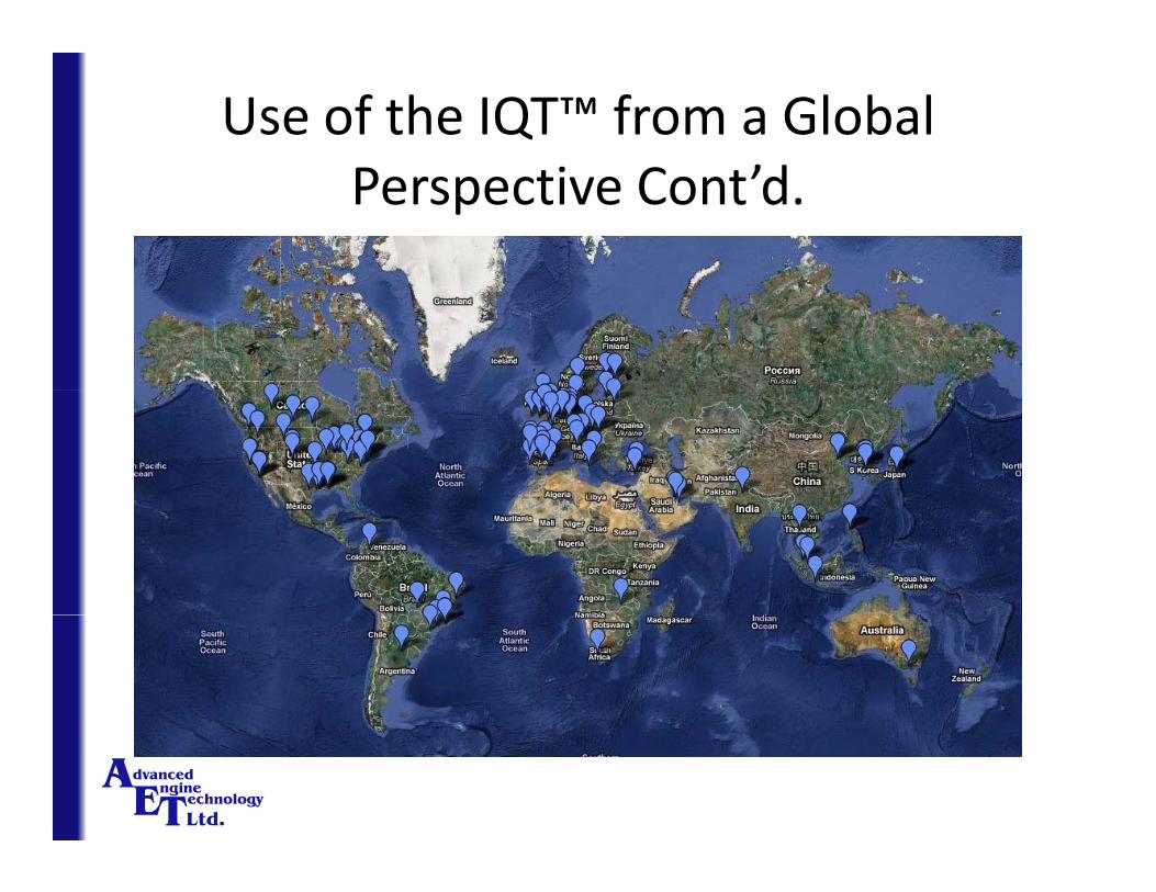
Use of the IQT™ from a Global Perspective
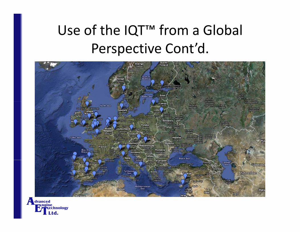
Region Number of IQT™sg QEurope 50
North America 46
Eastern Asia & Australia 17
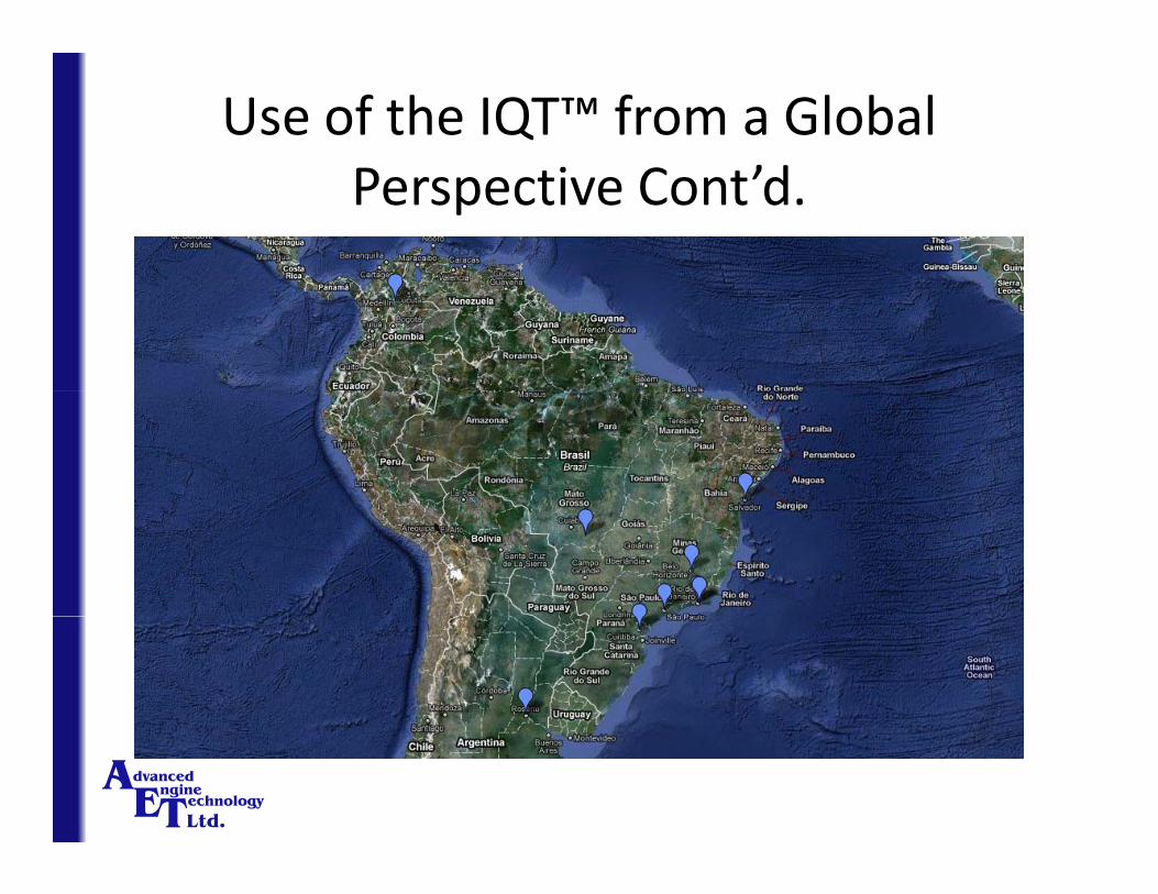
South America 10
Middle East, Western Asia & India 6Middle East, Western Asia & India 6
Africa 3

Use of the IQT™ from a Global ’dPerspective Cont’d.
Organization Type Number of IQT™sg yp QRefinery 57
Government Laboratory 19
Independent Testing Laboratory 18
Oil Company Laboratory 18
University/Research Laboratory 13University/Research Laboratory 13
Other 7
Use of the IQT™ from a Global ’dPerspective Cont’d.

Use of the IQT™ from a Global ’dPerspective Cont’d.
Use of the IQT™ from a Global ’dPerspective Cont’d.
Use of the IQT™ from a Global ’dPerspective Cont’d.

Use of the IQT™ from a Global ’dPerspective Cont’d.

Some of our Major IQT™ UsersSome of our Major IQT Users
The Significance of the IQT™ in Biodiesel l l d i li iFuel Development and Commercialization
• Over the past 10 years, the IQT™ has been utilized toOver the past 10 years, the IQT has been utilized to test B100 development fuels from approximately 50 different bio sources
• On all of these bio sources, there was never a single problem in providing a DCN indication (many ofproblem in providing a DCN indication (many of these fuels were tested well before the development of ASTM D6751) )
Effective use of the IQT™ with cetane improver (2‐ethy hexyl nitrate ‐2EHN and ditertiary butyl(2 ethy hexyl nitrate 2EHN and ditertiary butyl
peroxide ‐DTBP)
• Unlike the CFR engine, the IQT™ is sensitive to small concentrations of cetane improvers such as 2‐ethyl hexyl nitrate (2‐EHN) and ditertiary butyl peroxide (DTB).
Refinery use of the IQT™ with Cetane Improver
• Numerous refineries and research centers have beenNumerous refineries and research centers have been using their IQT™s to determine the level of boost for different base fuels with various cetane improver concentrations

IQT™ with Cetane Improver Cont’d.IQT with Cetane Improver Cont d.20
15
t
High response fuel
10
etan
e B
oost
5
Ce
Low response fuel
0 1000 2000 3000 40000
Amount of Additive (ppm)
Ghosh ‐ Energy & Fuels 2008Predicting the Effect of Cetane Improvers on Diesel Fuels

Effective use of the IQT™ in refinery diesel fuel blending optimization (establish blend values forblending optimization (establish blend values for
component blending)
• Establish DCN blend values for the blend components
• Determine the optimal dose rates for cetaneimprover
Effective use of the IQT™ in refinery diesel fuel blending optimization (establish blend values forblending optimization (establish blend values for
component blending)
• Determine cetane improver response with individual components
• As a result of IQT™ precision, a blend curve can be produced with as few as 4 tests for DCN
Regulatory use of the IQT™ for regular d d l f land premium diesel fuel
• Many countries, states, regions in the world haveMany countries, states, regions in the world have adopted fuel specifications that utilize ASTM D 6890 or EN 15195 in similar manner to that of ASTM D975, EN 590, D6751
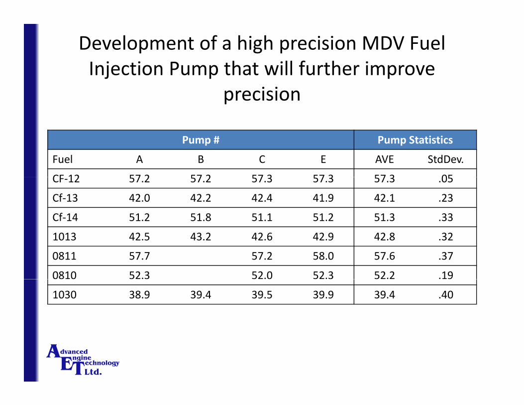
Development of a high precision MDV Fuel Injection Pump that will further improveInjection Pump that will further improve
precision
Pump # Pump Statistics
Fuel A B C E AVE StdDev.
CF 12 57 2 57 2 57 3 57 3 57 3 05CF‐12 57.2 57.2 57.3 57.3 57.3 .05
Cf‐13 42.0 42.2 42.4 41.9 42.1 .23
Cf‐14 51.2 51.8 51.1 51.2 51.3 .33
1013 42.5 43.2 42.6 42.9 42.8 .32
0811 57.7 57.2 58.0 57.6 .37
0810 52.3 52.0 52.3 52.2 .19
1030 38.9 39.4 39.5 39.9 39.4 .40
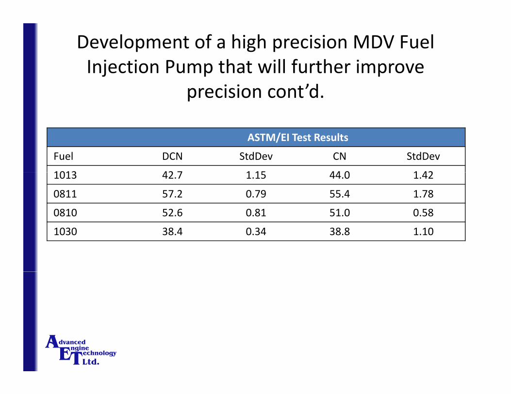
Development of a high precision MDV Fuel Injection Pump that will further improveInjection Pump that will further improve
precision cont’d.
ASTM/EI Test Results
Fuel DCN StdDev CN StdDev
1013 42 7 1 15 44 0 1 421013 42.7 1.15 44.0 1.42
0811 57.2 0.79 55.4 1.78
0810 52.6 0.81 51.0 0.58
1030 38.4 0.34 38.8 1.10
Precision UpdatePrecision Update
• There were 4 ballots to update the precision ofThere were 4 ballots to update the precision of D6890 at the December 2009 ASTM meeting– ASTM/EI Research Report
– Update Reproducibility
– Expand Scope
– Update Between Method Reproducibility
• All items are going to publication
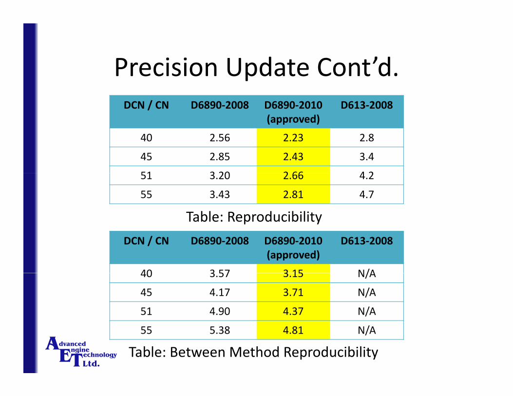
Precision Update Cont’d.Precision Update Cont d.DCN / CN D6890‐2008 D6890‐2010
(approved)D613‐2008
( pp )
40 2.56 2.23 2.8
45 2.85 2.43 3.4
51 3 20 2 66 4 251 3.20 2.66 4.2
55 3.43 2.81 4.7
Table: Reproducibility p y
DCN / CN D6890‐2008 D6890‐2010(approved)
D613‐2008
40 3 57 3 15 N/A40 3.57 3.15 N/A
45 4.17 3.71 N/A
51 4.90 4.37 N/A
55 5.38 4.81 N/A
Table: Between Method Reproducibility
Precision Update StatusPrecision Update Status
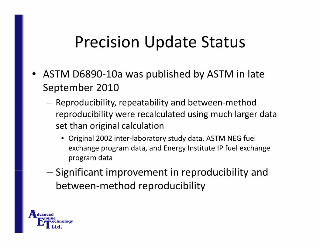
• ASTM D6890‐10a was published by ASTM in lateASTM D6890 10a was published by ASTM in late September 2010– Reproducibility, repeatability and between‐method reproducibility were recalculated using much larger data set than original calculation
• Original 2002 inter‐laboratory study data ASTM NEG fuelOriginal 2002 inter laboratory study data, ASTM NEG fuel exchange program data, and Energy Institute IP fuel exchange program data
Significant impro ement in reprod cibilit and– Significant improvement in reproducibility and between‐method reproducibility
Precision Update Status Cont’dPrecision Update Status Cont d
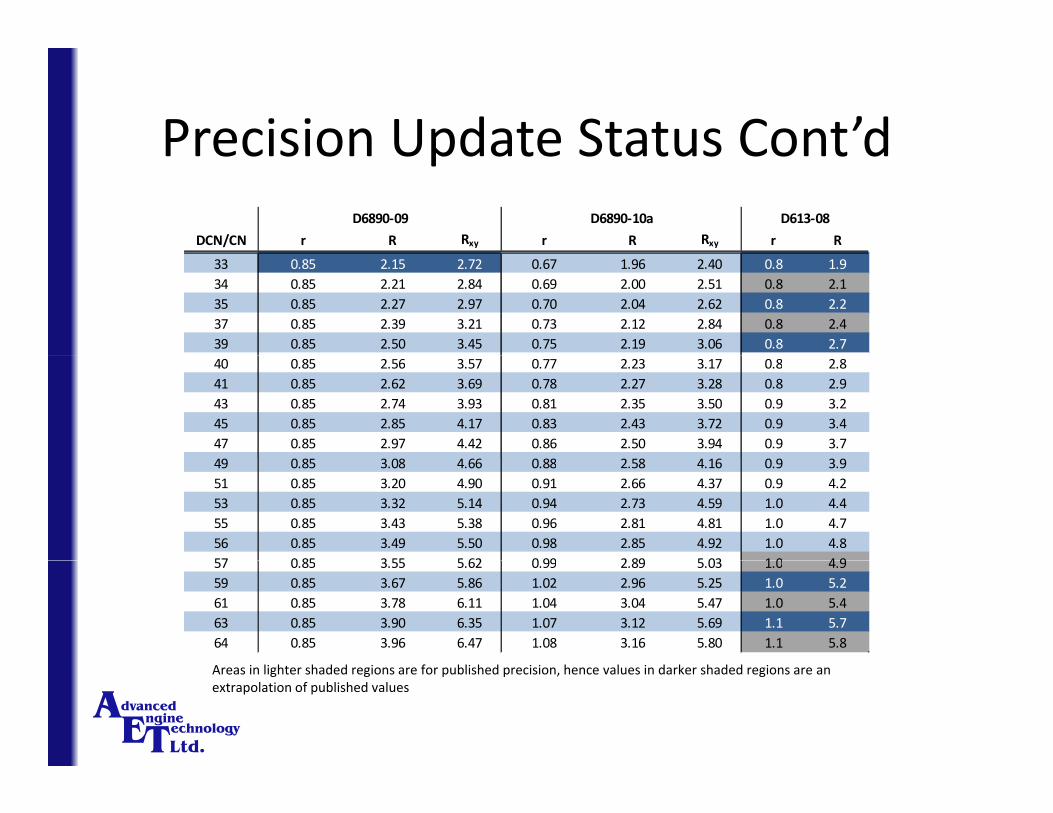
DCN/CN r R Rxy r R Rxy r R
D6890‐09 D6890‐10a D613‐08
33 0.85 2.15 2.72 0.67 1.96 2.40 0.8 1.934 0.85 2.21 2.84 0.69 2.00 2.51 0.8 2.135 0.85 2.27 2.97 0.70 2.04 2.62 0.8 2.237 0.85 2.39 3.21 0.73 2.12 2.84 0.8 2.439 0.85 2.50 3.45 0.75 2.19 3.06 0.8 2.740 0.85 2.56 3.57 0.77 2.23 3.17 0.8 2.841 0.85 2.62 3.69 0.78 2.27 3.28 0.8 2.943 0.85 2.74 3.93 0.81 2.35 3.50 0.9 3.245 0.85 2.85 4.17 0.83 2.43 3.72 0.9 3.447 0.85 2.97 4.42 0.86 2.50 3.94 0.9 3.749 0.85 3.08 4.66 0.88 2.58 4.16 0.9 3.951 0.85 3.20 4.90 0.91 2.66 4.37 0.9 4.253 0.85 3.32 5.14 0.94 2.73 4.59 1.0 4.455 0.85 3.43 5.38 0.96 2.81 4.81 1.0 4.756 0.85 3.49 5.50 0.98 2.85 4.92 1.0 4.857 0 85 3 55 5 62 0 99 2 89 5 03 1 0 4 957 0.85 3.55 5.62 0.99 2.89 5.03 1.0 4.959 0.85 3.67 5.86 1.02 2.96 5.25 1.0 5.261 0.85 3.78 6.11 1.04 3.04 5.47 1.0 5.463 0.85 3.90 6.35 1.07 3.12 5.69 1.1 5.764 0.85 3.96 6.47 1.08 3.16 5.80 1.1 5.8
Areas in lighter shaded regions are for published precision, hence values in darker shaded regions are an extrapolation of published values
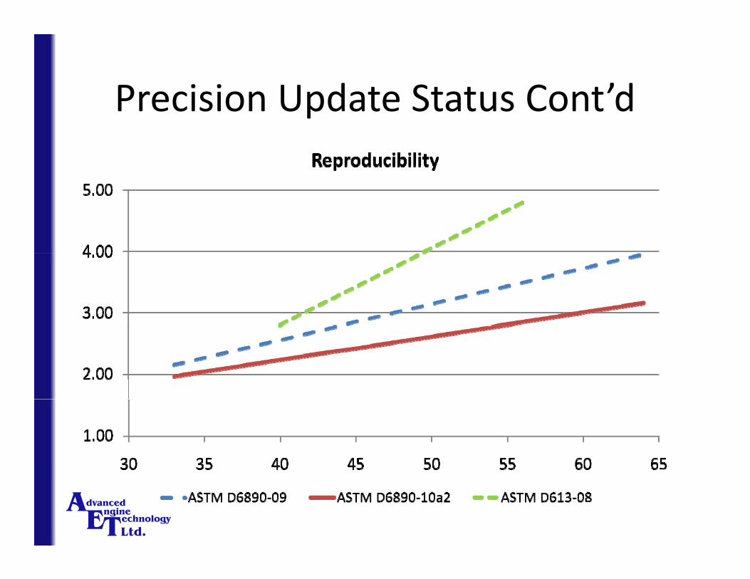
Precision Update Status Cont’dPrecision Update Status Cont d
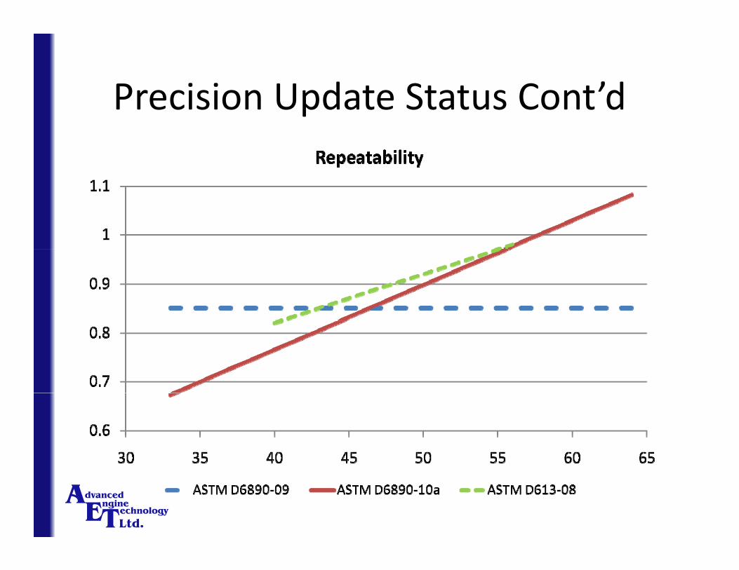
Precision Update Status Cont’dPrecision Update Status Cont d

Precision Update StatusPrecision Update Status
• ASTM NEG Fuel Exchange Program
Year DCN σ # Labs CN σ # Labs
2003 45.58 1.12 5 45.09 1.19 17
ASTM NEG Fuel Exchange Program
2003 45.58 1.12 5 45.09 1.19 17
2004 48.06 0.82 4 48.18 1.34 18
2005 45.18 0.80 6 45.04 1.55 19
2006 47 38 0 99 7 47 74 1 50 212006 47.38 0.99 7 47.74 1.50 21
2007 44.90 0.96 6 44.67 1.26 20
2008 47.05 0.93 8 47.70 1.19 21
2009 45.90 0.95 8 45.34 1.37 21
2010* 47.11 0.97 10 47.49 1.26 22
Average 46 36 0 94 7 46 36 1 34 20Average 46.36 0.94 7 46.36 1.34 20
* 2010 data up to August 2010

Precision Update StatusPrecision Update Status
• Energy Institute IP Fuel Exchange Program
Year DCN σ # Labs CN σ # Labs
2006 52.90 1.00 9 52.30 1.42 18
Energy Institute IP Fuel Exchange Program
2006 52.90 1.00 9 52.30 1.42 18
2007 51.46 0.78 12 51.29 1.53 18
2008 52.46 0.89 14 52.63 1.10 15
2009 52 30 0 88 15 52 01 1 33 182009 52.30 0.88 15 52.01 1.33 18
2010* 51.97 0.83 18 51.94 1.54 18
Average 52.23 0.91 12 51.94 1.40 18
* 2010 data up to August 2010

Update on Refinery On‐Line Model ( )(ROLM) IQT™
• Automated Bleed Valve SystemAutomated Bleed Valve System– Fuel system flushing between samples
– Torque‐limiting mechanism
New Reference FuelsNew Reference Fuels
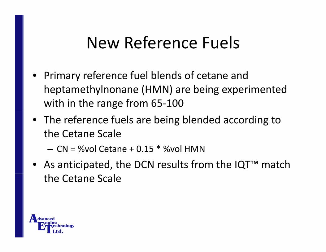
• Primary reference fuel blends of cetane andPrimary reference fuel blends of cetane and heptamethylnonane (HMN) are being experimented with in the range from 65‐100
• The reference fuels are being blended according to the Cetane Scale – CN = %vol Cetane + 0.15 * %vol HMN
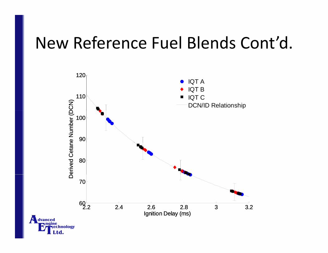
• As anticipated, the DCN results from the IQT™ match the Cetane Scale
New Reference Fuel Blends Cont’d.New Reference Fuel Blends Cont d.
120 120
110
DC
N)
IQT020IQT077IQT120DCN/ID Relationship
110
DC
N)
IQT AIQT BIQT CDCN/ID Relationship
90
100
ne N
umbe
r (D
90
100
ne N
umbe
r (D
80
eriv
ed C
etan
80
eriv
ed C
etan
2 2 2 4 2 6 2 8 3 3 260
70
D
2 2 2 4 2 6 2 8 3 3 2
60
70
D
2.2 2.4 2.6 2.8 3 3.2
Ignition Delay (ms)2.2 2.4 2.6 2.8 3 3.2
Ignition Delay (ms)

Scope Expansion (>65CN, <30CN)Scope Expansion (>65CN, <30CN)
• The results from the experiments are very promisinge esu s o e e pe e s a e e y p o s g
• Additional tests have shown that HMN is 15DCN using the IQT, which is its definition
• The primary reference fuels will be used to expand the scope of D6890 from 15‐33 and 65‐100 DCN
• This would permit the IQT™ conversion equation to be anchored at three additional points: 15, 65, and 100 DCN
• Anchoring the IQT™ conversion equation to the Cetane• Anchoring the IQT™ conversion equation to the Cetane Scale will enable it to be considered a standalone method

Reference Fuels PackageReference Fuels Package
• Quality controlled reference fuels are available for allQuality controlled reference fuels are available for all operators from AET:– Heptane
– MCH
– Low Cetane Check Fuel
– High Cetane Check Fuel
– 65.2 DCN Fuel

Durability track record and recent d b ldurability improvements
• Some heavy use refineries have utilized the IQT™ forSome heavy use refineries have utilized the IQT for more than 28,000 tests or 1,250,00 combustion events
• Exhaust and intake air valves have been removed as a frequent repair component
• Fuel injection nozzles can last from 6 months to 2 or more years

Update on Near ‐ Totally Automated b d l ( )Laboratory Model (n ‐ TALM) IQT™
• Electronic pressure control (UG Driven)Electronic pressure control (UG Driven)
Set point adjustment
Gas hook‐ups
adjustment controls
Nitrogen pressure display

Update on Near ‐ Totally Automated b d l ( ) ’dLaboratory Model (n ‐ TALM) IQT™ Cont’d.
• Automatic flushing (fuel injector nozzle)Automatic flushing (fuel injector nozzle)
Pneumatic actuator
Solenoid valve
Standard IQT™ bleed valve

Update on Near ‐ Totally Automated b d l ( ) ’dLaboratory Model (n ‐ TALM) IQT™ Cont’d.
• Automatic flushing (fuel injection pump)Automatic flushing (fuel injection pump)
Pneumatic actuator
Standard IQT™ bleed valvebleed valve
Solenoid valve

Update on Near ‐ Totally Automated b d l ( ) ’dLaboratory Model (n ‐ TALM) IQT™ Cont’d.
• New drip free fuel reservoir (UG Driven)New drip free fuel reservoir (UG Driven)

Update on Near ‐ Totally Automated b d l ( ) ’dLaboratory Model (n ‐ TALM) IQT™ Cont’d.
• New enclosure design will be unveiled in NovemberNew enclosure design will be unveiled in November 2010
Update on Near ‐ Totally Automated b d l ( ) ’dLaboratory Model (n ‐ TALM) IQT™ Cont’d.
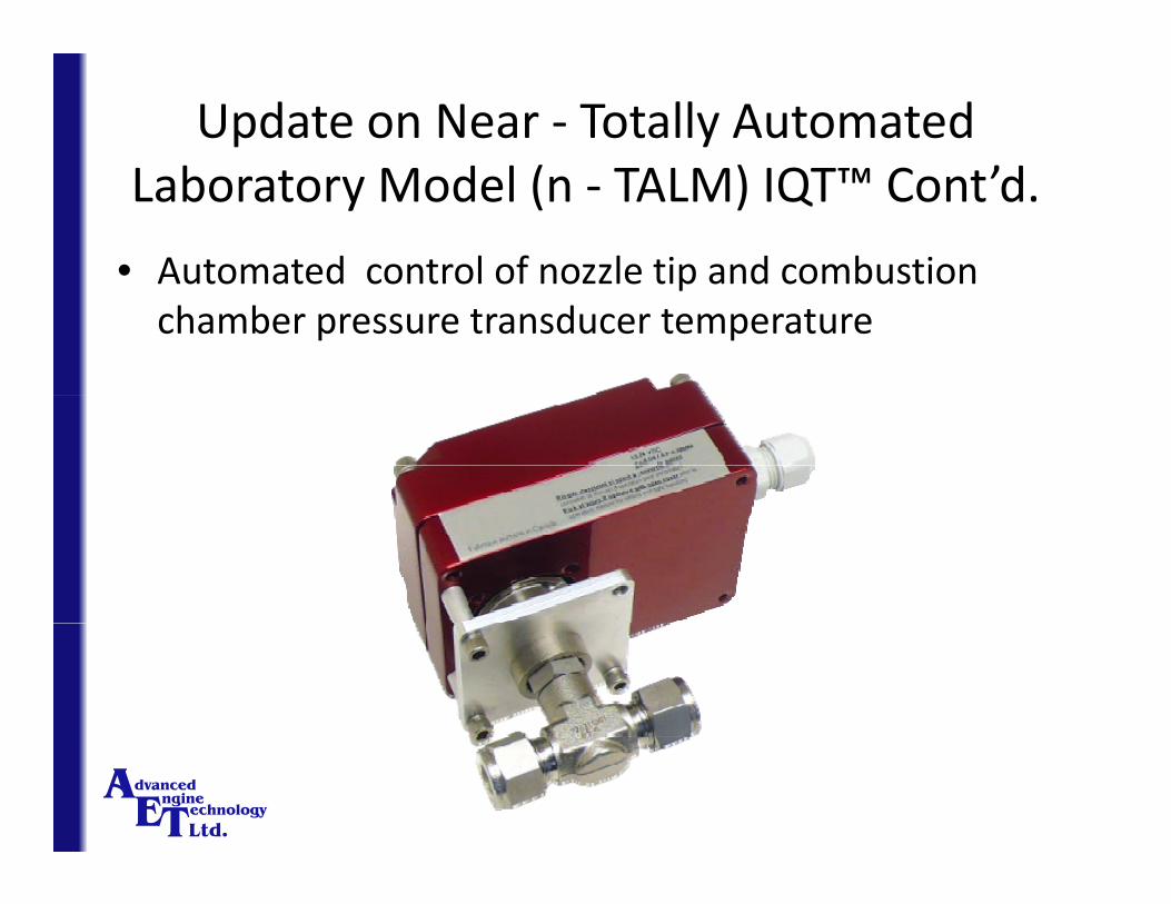
• Automated control of nozzle tip and combustionAutomated control of nozzle tip and combustion chamber pressure transducer temperature
Update on Near ‐ Totally Automated b d l ( ) ’dLaboratory Model (n ‐ TALM) IQT™ Cont’d.
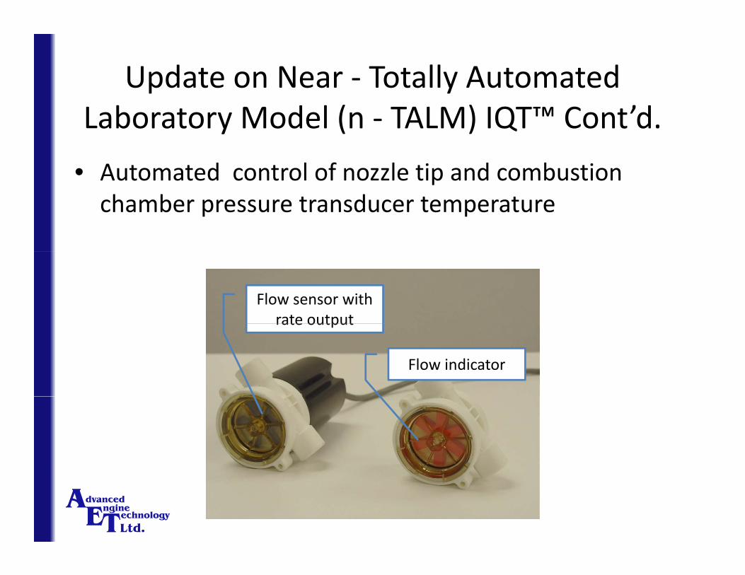
• Automated control of nozzle tip and combustionAutomated control of nozzle tip and combustion chamber pressure transducer temperature
Flow sensor with rate outputrate output
Flow indicator

Update on Near ‐ Totally Automated b d l ( ) ’dLaboratory Model (n ‐ TALM) IQT™ Cont’d.
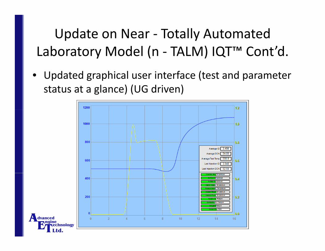
• Updated graphical user interface (test and parameterUpdated graphical user interface (test and parameter status at a glance) (UG driven)
Update on Near ‐ Totally Automated b d l ( ) ’dLaboratory Model (n ‐ TALM) IQT™ Cont’d.
• Updated graphical user interface (test and parameterUpdated graphical user interface (test and parameter status at a glance) (UG driven)
Update on Near ‐ Totally Automated b d l ( ) ’dLaboratory Model (n ‐ TALM) IQT™ Cont’d.
• Automated ‐ Self checking of calibrationAutomated Self checking of calibration– Verify SQC fuel test results against quality control limits
– Prompt to start automatic calibration procedure if required
• Automated ‐ Self calibration– Determine change in set point required to achieve ARV for g p qn‐heptane and verify that new set point is correct
– Verify the instrument’s measurement sensitivity using th l l hmethylcyclohexane
– Perform post‐calibration quality control test
Update on Near ‐ Totally Automated b d l ( ) ’dLaboratory Model (n ‐ TALM) IQT™ Cont’d.
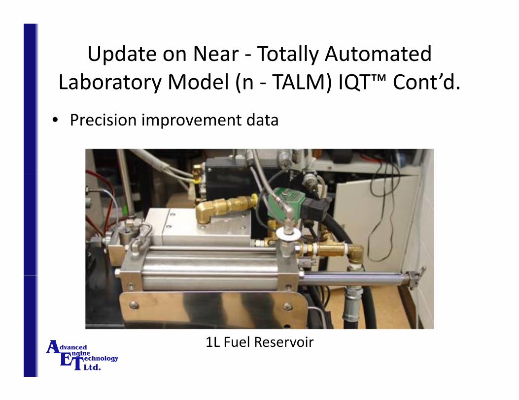
• Precision improvement dataPrecision improvement data
1L Fuel Reservoir
Update on Near ‐ Totally Automated b d l ( ) ’dLaboratory Model (n ‐ TALM) IQT™ Cont’d.
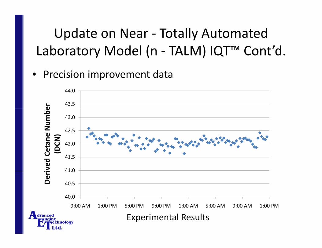
• Precision improvement dataPrecision improvement data
43.5
44.0
er
42.5
43.0
ne Num
beN)
41 0
41.5
42.0
ived
Cetan
(DCN
40.0
40.5
41.0
Deri
9:00 AM 1:00 PM 5:00 PM 9:00 PM 1:00 AM 5:00 AM 9:00 AM 1:00 PM
Experimental Results

Update on Near ‐ Totally Automated b d l ( ) ’dLaboratory Model (n ‐ TALM) IQT™ Cont’d.
• The new enclosure will further improve instrumentThe new enclosure will further improve instrument safety
Ease of MaintenanceEase of Maintenance
• Use of bellville washers on the three combustionUse of bellville washers on the three combustion chamber studs mean that high temperature gasket life is greatly extended
• The new enclosure will permit easier access for periodic maintenanceperiodic maintenance

SummarySummary
• From 1993 to 2010 work has been ongoing toFrom 1993 to 2010 work has been ongoing to improve the capability, precision, and durability of the IQT™
• New developments for the Totally Automated Laboratory Model (TALM) IQT™ will further itsLaboratory Model (TALM) IQT will further its capability and durability characteristics for use with a broad range of fuel options over a cetane range of 15 g p gto 100
![Two-stage Lagrangian modeling of ignition processes in ...2].JFUE.10824pdf.pdfThe ignition characteristics of iso-octane and n-heptane in an ignition quality tester (IQT) were simulated](https://img.pdfslide.us/doc/110x75/60866c6f3e62e055d82d0a93/two-stage-lagrangian-modeling-of-ignition-processes-in-2jfue-the-ignition.jpg)