Embed Size (px)
Citation preview
IGCSE Resistant Material
International General Certification of Secondary Education
Design and Technology – 0445
Student Name: Tutor Group:
Introduction International General Certificate of Secondary Education (IGCSE) syllabuses are designed as two year courses for examination at age 16-plus. All IGCSE syllabuses follow a general pattern. The main sections are:
• Aims • Assessment Objectives • Assessment • Curriculum Content.
The IGCSE subjects have been categorised into groups, subjects within each group having similar aims and assessment objectives. Design and Technology falls into Group V, Creative Technical and Vocational, of the International Certificate of Education (ICE) subjects. The Design and Technology syllabus has been designed for Centres which are attempting to move towards a greater emphasis on design – the reasoned application of the knowledge, skills and discipline normally taught in the subject in problem solving situations.
Aims The aims of the syllabus are the same for all students. The aims are set out below and describe the educational purposes of a course in Design and Technology for the IGCSE examination. They are not listed in order of priority. The aims are to enable students to:
1. foster awareness, understanding and expertise in those areas of creative thinking
which can be expressed and developed through investigation and research, planning, designing, making and evaluating, working with media, materials and tools;
2. encourage the acquisition of a body of knowledge applicable to solving
practical/technological problems operating through processes of analysis, synthesis and realisation;
3. stimulate the development of a range of communication skills which are central
to design, making and evaluation;

4. stimulate the development of a range of making skills; 5. encourage students to relate their work, which should demand active and
experimental learning based upon the use of materials in practical areas, to their personal interests and abilities;
6. promote the development of curiosity, enquiry, initiative, ingenuity,
resourcefulness and discrimination 7. encourage technological awareness, foster attitudes of co-operation and social
responsibility, and develop abilities to enhance the quality of the environment; 8. stimulate the exercising of value judgements of an aesthetic, technical,
economic and moral nature.
Assessment Objectives The four assessment objectives in Design and Technology are: A Knowledge with understanding
B Problem solving
C Communication
D Realisation.
A description of each assessment objective follows. Under each assessment objective heading is given a list of the activities a student should be able to carry out.
A - Knowledge with Understanding Students should be able to: 1. demonstrate the ability to state facts, recall and name items, recall and describe processes; 2. demonstrate the ability to apply and relate knowledge to designing and making; 3. make reasoned arguments and anticipate consequences about the outcomes of the Design and Technology process; 4. demonstrate a crucial awareness of the interrelationship between Design and the needs of society.
B – Problem Solving Students should be able to: 5. recognise problems, identify clearly, from a problem situation, a specific need for which a solution is required and compose a design brief; 6. analyse a problem by considering any relevant functional, aesthetic, human, economic and environmental design factors and draw up a design specification; 7. investigate, research, collect and record relevant data and information; 8. generate a range of outline solutions to a design problem, giving consideration to the constraints of time, cost, skill and resources; 9. develop, refine, test and evaluate the effectiveness of design solutions. C - Communication Students should be able to: 10. recognise information in one form and where necessary change it into a more applicable form; 11. produce or interpret data in a variety of forms such as charts, diagrams, graphs, and flow charts; 12. propose and communicate ideas graphically using a range of media; 13. develop ideas and represent details of form, shape, construction, movement, size, and structure through graphical representation and three dimensional modelling.
D - Realisation Students should be able to: 14. plan and organise the work procedure involved in the realisation of a solution; 15. select, from a range of resources, those appropriate for the realisation of the product; 16. demonstrate appropriate manipulative skills by showing an understanding of materials and their characteristics in relation to their use; 17. evaluate the process and product in terms of aesthetic, functional and technical quality.
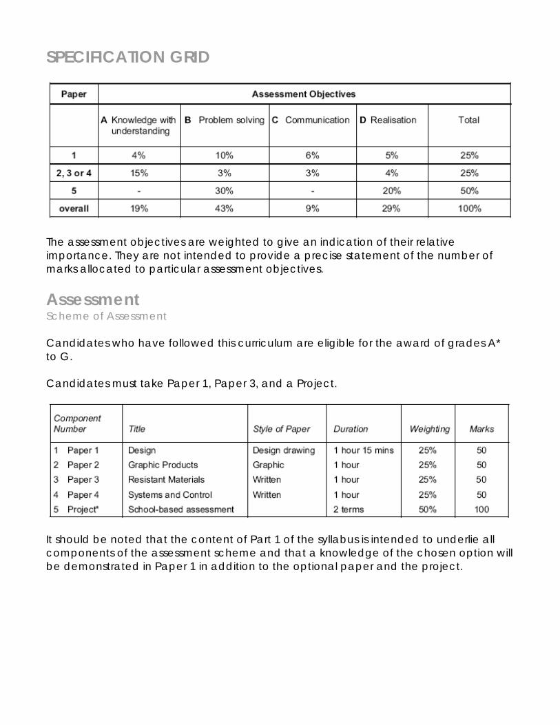
SPECIFICATION GRID
The assessment objectives are weighted to give an indication of their relative importance. They are not intended to provide a precise statement of the number of marks allocated to particular assessment objectives.
Assessment Scheme of Assessment Candidates who have followed this curriculum are eligible for the award of grades A* to G. Candidates must take Paper 1, Paper 3, and a Project.
It should be noted that the content of Part 1 of the syllabus is intended to underlie all components of the assessment scheme and that a knowledge of the chosen option will be demonstrated in Paper 1 in addition to the optional paper and the project.
Description of Papers Paper 1 This question paper will be set on Part 1 of the syllabus. Candidates will be required to answer one of 3 open ended questions intended to assess the candidates’ abilities of analysis and synthesis. The range of questions will reflect the breadth of optional content. Paper 3 Candidates will be entered for this optional paper. In each of these papers there will be a Section A and a Section B. Section A will consist of compulsory questions, testing subject knowledge in the chosen option. Section B will consist of longer structured questions. Papers 3 will provide a choice of one out of three questions in this section. Paper 5, School-based assessment Each candidate will undertake a personally identified Project centred on the chosen option from Part 2 of the syllabus. The Project, which will be internally marked and externally moderated, is expected to be worked over the final two terms of the course. While the Project will be option based, the nature of the Common Core within the subject Design and Technology is such that each candidate’s work is likely to be of a cross-optional character. The work presented for assessment will typically be in the form of an A3 size folder and the ‘made product’. In the case of work from the Graphic Products option the folder could contain all the preliminary design work, with the ‘made product’ being in the form of 2 dimension work and models. The folder must include sufficient photographs of the made product, showing an overall view together with detailed views of evidence to support the award of marks for assessment criterion 6 ‘Product Realisation’. (See External Moderation section of the Assessment Criteria for coursework). Candidates whose work is required for external moderation will be selected by CIE.
Curriculum Content The curriculum objectives in Part 1 are to be followed by all students. This will be assessed specifically in Paper 1 (Design) and Coursework. It is envisaged that this core content will also be covered, in an integrated manner in the teaching of the optional specialist area from Part 2.
PART 1
Candidates should be able to:
Observe need/requirement identify and describe needs and opportunities for design and technological improvement;
Design brief/specification analyse and produce design
specifications for problems which have been self-identified or posed by others;
Identification/research identify the constraints imposed by
knowledge, resource availability and/or external sources which influenced proposed solutions;
gather, order and assess information relevant to the solution of practical/technological problems; produce and/or interpret data (e.g. diagrams, flow charts, graphs, experimental and test results);
Generation of possible ideas generate and record ideas as
potential solutions to problems using a range of techniques;
identify the resources needed for the solution of practical/technological problems; use a variety of media and equipment to produce models and mock-ups as a means of exploring a
problem and as a means of testing the feasibility of a solution;
recognise the need for continuous appraisal of their own progress, thinking and decision making, in order to provide themselves with opportunities for review; relate these judgements to the purpose of their study, in particular the specification which they set themselves;
Selection/organization select and develop a solution after
consideration of time, cost, skill and resources;
organise and plan in detail the production of the selected solution;
Evaluation evaluate existing products/systems,
the work of others and their own work;
check the performance of the product/solution against the original specification; use different methods and sources to assess the effectiveness of a product (e.g. sampling, questionnaires, interviews); suggest any possible modification and improvements (consideration to include functional, safety, aesthetic, ergonomic and economic factors);
Implementation and realisation show an awareness of correct
procedures for their preparation;
show an awareness of the correct and accurate methods of drawing, marking out and testing;

select appropriate processes for shaping, forming, cutting, joining, fitting, assembling and finishing a variety of materials;
Health and Safety show an awareness of the correct use
of hand and machine tools and equipment;
show a proper regard for all mandatory and other necessary safety precautions relevant to the use of a variety of tools, machines, materials and other resources; show a concern for economy in the use of materials, components, media, time, energy and other resources;
Initiation and development of ideas, extract relevant information from and recording of data sources(written, graphical, oral,
computer based);
interpret and record information and data;
Communicating ideas with others use technical vocabulary, number
skills, colour, shading and other media to produce sketches, models, diagrams, drawings (such as perspective, isometric, orthographic, sequential) and written materials, which communicate their ideas with precision and clarity;
Design and Technology in Society show awareness of the effect of
design and technology activity on social, environmental and economic issues;
demonstrate awareness of the role of designers, craftsmen and technologists in industry and society;

take account of human needs in aspects as diverse as aesthetic, ergonomic, economic, environmental, cultural and social;
Aesthetics appreciate the use of line, shape,
form, proportion, space, colour and texture as appropriate to their designed solutions and the work of others;
Anthropometrics and Ergonomics demonstrate an understanding of the
concept of ergonomics and the use of anthropometric data in their own design work and that of others;
Energy recognise that different forms of
energy sources exist, namely, fossil fuels, nuclear, solar, water power;
understand how different sources and forms of energy can be stored, converted and transmitted to produce a work capability and to improve the quality of life; understand the inefficiencies of energy conversion methods, e.g. ‘losses’ into by-products such as heat, light and sound; understand the difference between the finite and almost finite nature of energy sources and how through design, all energy sources can be conserved; use energy sources effectively and efficiently;
Control identify the features of a control
system in terms of input devices, processing elements, output devices, feedback;
Mechanical Control (Static) understand the use of common
fastenings and fittings applicable to the holding of metal, wood, plastics, card and paper;
Permanent Fastenings choose sensibly between common
and appropriate methods applicable to most common materials; this should include simple joining, the use of adhesives, riveting and welding;
Mechanical Control (Dynamic) understand methods of transmitting
motion using simple systems only; examples should include belts, chains, pulleys, gears and cams.
Resistant Materials It is recommended that the approach to the following objectives should be a practical one wherever possible and that their delivery to students be used as the vehicle for delivering the content of Paper 1 such that the syllabus is seen as an integrated area of study. Introduction This area of study is concerned with developing the skills used by designers within the context of materials and their processing. It is intended that practical experience be used to create a broad understanding of materials and their processing rather than an in-depth knowledge of any particular material, technology or process through the following headings: the general physical and working properties of common constructural materials, i.e.; plastics, woods and metals, in relation to specific designing and making tasks; simple comparative testing leading to the reasoned selection of materials and processes for specific design and making tasks.

Candidates should be able to: Practical Applications design and make practical products
using the concepts, knowledge and skills listed in this syllabus;
Types of Material understand the physical and working
properties and application in relation to plastics, woods and metals;
Plastics show a working knowledge of the
following:
(i) thermoplastics - nylon, polythene, polyvinyl chloride (PVC), acrylic, polystyrene, polypropylene;
(ii) thermosetting plastics -
polyester resin including GRP, melamine, urea formaldehyde and phenol formaldehyde;
Woods show a working knowledge of natural
timbers, understand their classification, properties and uses;
understand why timber is seasoned and how to care for timber during storage and construction; show a working knowledge of the following manufactured boards: − plywood, blockboard, chipboard, hardboard and MDF;
Metals show a working knowledge of the
following metals:
− ferrous metals (mild and high carbon steels); − non-ferrous metals (aluminium, duralumin and other common casting alloys, copper and its alloys, zinc, lead and tin);
Practical Applications Preparation of Materials show knowledge of available market
forms, types and sizes;
understand methods of cutting by use of hacksaw, guillotine, tenon saw, cross-cut saw, panel saw and portable power tools; understand the use of datum surfaces/lines/ edges and be able to produce them by planing or filing; explain the preparation for machine processes and safe methods of securing materials to work surfaces, work tables, faceplates, lathe chucks and between centres on a lathe;
Setting/Marking Out measure and/or mark out work using
rule, pencil, marker pen, scriber, try square, bevel, dot/centre punch, dividers, marking gauge, cutting gauge and mortise gauge;
accurately produce datum lines by surface plate and scribing block or callipers; accurately measure using a micrometer and a vernier gauge.
Shaping (a) Deforming/Reforming Have knowledge of the following
processes:
− bending, simple casting, lamination; vacuum forming; blow moulding; injection moulding; extrusion;
(b) Wastage/Addition select and perform the following forms of cutting and removal of material, and joining and adding to a material to produce the required shape, form r contour: − use hand snips, saws, files, basic planes and abrasive cutters; − simple hole boring by hand or machine including pilot, clearance, tapping, countersunk and counterbored holes; − use taps and dies for screw cutting by hand; − use planes, chisels, gouges, saws, files and rasps; − use abrasive mops, discs and belts;
Special Treatments understand how the molecular
structure of a material can be changed by the following processes, to make it more or less suitable for the task it has to perform:
− work hardening, annealing all metals, case hardening of mild steel and hardening and tempering tool steel (HCS); understand the term plastic memory and its significance; understand steaming and bending of timbers and have knowledge of adhesives curing times and strengths;
Joining and Assembly use various methods of fabrication
and fitting to join parts of a desired structure. Allow any required movement, to enable it to perform its task satisfactorily (permanently or temporarily);

understand methods of carcase, stool and frame construction using permanent and temporary joints; use holding devices, formers and jigs to assist joining and assembly; understand the use of KD (knock-down) fittings for use with modern materials such as veneered chipboard; use a variety of fittings and adhesives;
Finishing understand the preparation for and
application of surface treatments;
be aware of a range of different finishes including oils, paints, laquers, stains, satin polishes, dipcoating; be aware of surface finishes available for both interior and exterior use; be aware of the special finishes available that will prevent corrosion or stains, or withstand heat or liquids.
IGCSE Resistant Material
Topic: Materials
Student Name: Tutor Group:
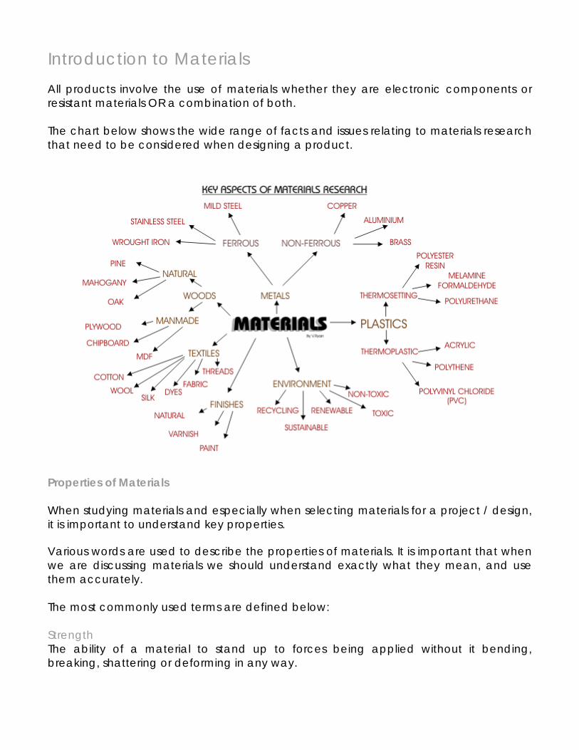
Introduction to Materials All products involve the use of materials whether they are electronic components or resistant materials OR a combination of both. The chart below shows the wide range of facts and issues relating to materials research that need to be considered when designing a product.
Properties of Materials When studying materials and especially when selecting materials for a project / design, it is important to understand key properties. Various words are used to describe the properties of materials. It is important that when we are discussing materials we should understand exactly what they mean, and use them accurately. The most commonly used terms are defined below: Strength The ability of a material to stand up to forces being applied without it bending, breaking, shattering or deforming in any way.
Elasticity The ability of a material to absorb force and flex in different directions, returning to its original position. Plasticity The ability of a material to be change in shape permanently. Ductility The ability of a material to change shape (deform) usually by stretching along its length. Tensile Strength The ability of a material to stretch without breaking or snapping. Compressive Strength The ability of a material to stand squeezing or crushing. Shear Strength The ability of a material to resist being parted. Malleability The ability of a material to be reshaped in all directions without cracking Toughness A characteristic of a material that does not break or shatter when receiving a blow or under a sudden shock. Hardness The ability of a material to resist scratching, wear and tear and indentation. Heat and Electrical Conductivity It is a measure of how well the material will conduct heat or electricity Thermal conductivity It relates to how heat travels, or is conducted through a material from a hotter part to a colder part. Stability It is the resistance to changes in shape and size. Plasticity It is the ability to be permanently changed in shape by external blows or pressure without cracking or breaking.
How a tree grows Roots These absorb water and mineral salts, and make crude sap. Sapwood This carries crude sap to the leaves. Leaves Plant food is manufactured in the leaves by the process of
photosynthesis. In the process sugars are formed out of water (from the sap) and carbon dioxide (from the air) using energy absorbed by chlorophyll from sunlight.
Bast This carries plant food down from the leaves to all parts of the tree. Medullary rays Carry plant food from the bast into the cambium layer, sapwood,
and heartwood, and store it. Cambium layer This contains cells capable of division to produce sapwood cells on
the inside and bast cells on the outside, to make the tree grow. Sapwood Is the living part of the tree. It consists of cellulose cells which have
thin walls capable of absorbing moisture from the roots, and plant food to grow.
Heartwood Is the commercially most useful part of the tree. It consists of cells
which have become clogged with gum and die. They are stronger, more durable, and more resistant to insect and fungal attack than sapwood, and provide the strength to support the tree. A young tree consists mainly of sapwood but as it grows it makes heartwood. Waste products are stored here.
Pith Is the centre of the trunk consisting of the original sapling, from which
the tree grew, and is often soft. Bark Is a protective covering to protect the tree from damage and
extremes of temperature. It is made from the outer layers of bast as they die, and consists of a soft inner layer which expands as the tree grows and a hard outer layer.
Annual rings Each represents one year’s growth. In spring, the cambium layer
makes wide thin-walled cells so that a large amount of sap can each the leaves quickly. These cells are pale, soft and weak. In summer, the tree needs less sap, and so it makes narrow cells with thick walls which are dark, hard and strong. In winter, the tree rests and no sap flows. This cycle gives alternate pale and dark annual rings from which we can count the age of softwood trees.
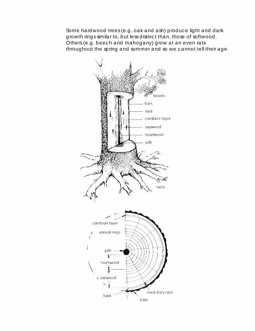
Some hardwood trees (e.g. oak and ash) produce light and dark
growth rings similar to, but less distinct than, those of softwood. Others (e.g. beech and mahogany) grow at an even rate throughout the spring and summer and so we cannot tell their age.

Hardwoods and softwoods Hardwoods These are produced by broad leaved trees (having leaves broad in width in proportion to their length) whose seeds are enclosed in fruit (e.g. apple, acorn). They show a wide range of colours and gain patterns and are divided into two groups. Deciduous hardwoods These trees lose their leaves in winter. They grow in warmer temperate climates (including the British Isles, Europe, Japan, New Zealand, Chile and Central USA), and are slow growing (100 years) and expensive. Common examples include: Oak, Ash, Elm, Beech, Birch, Chestnut, Lime, Sycamore, Walnut, Apple and Pear. Evergreen hardwoods These trees keep their leaves all the year round, and therefore grow more quickly and to a greater size. They are usually softer and easier to work than deciduous hardwoods. They grow mainly in tropical and sub-tropical climates (including most of South America, Central America, Indo-China, Africa, Burma, India, and the East and West Indies). Common examples include: Mahogany, teak, African Walnut, Afrormosia, Iroko, Rosewood, Ebony, Balsa and Sapele. There are two European evergreen hardwoods, the holly and the laurel. Softwoods These are produced by conifers (cone bearing trees). They are usually evergreen with needle-like leaves, and grow mainly in colder and cooler temperate climates (including Scandinavia, Canada, Northern Russia, and at high altitudes elsewhere. They grow quickly (30 years) and are therefore cheaper, softer and easier to work than hardwoods. The seeds are not enclosed, but are held in cones. Common examples include: the many types of Pines, Spruce, Fir, Cedar, Larch and Giant redwood. Yew is a coniferous three which does not produce cones. Larch is the only deciduous coniferous tree. Note: The names softwood and hardwood describe the leaves, seeds and structure of the trees, and not necessarily the timber produced. As a result, some hardwoods (notably Balsa) are light in weight and very soft to work, while some softwoods (e.g. Yew and Pitch Pine) are heavy and hard to work.

Commonly available forms of hardwoods and softwoods Remember when ordering timber that the widths and thicknesses of all timbers are given as the rough sawn sizes. You can buy machine-planed timber either planed on both sides (PBS) or planed all round (PAR), but its size will still be describe as the nominal (rough sawn)size, although it will actually be approximately 3mm smaller in thickness and if PAR in width too. A board is a piece of wood less than 40mm thick and 75mm, or over, wide. • Common thicknesses are 12, 16, 19, 22 and 25mm. • Common widths for softwood are from 75mm to 225mm. • Common widths for hardwood are from 150mm to 330mm. • Lengths normally start at 1.8 metres and go up to 6.3 metres. A plank is a piece of wood over 40mm thick. Squares are square sections. Common sizes for square are 25mm x 25mm, 38mm x 38mm, and 50mm x 50mm. Strips are rectangular sections narrower than 75mm wide. Common sizes for strips are 25mm x 38mm and 25mm x 50mm.
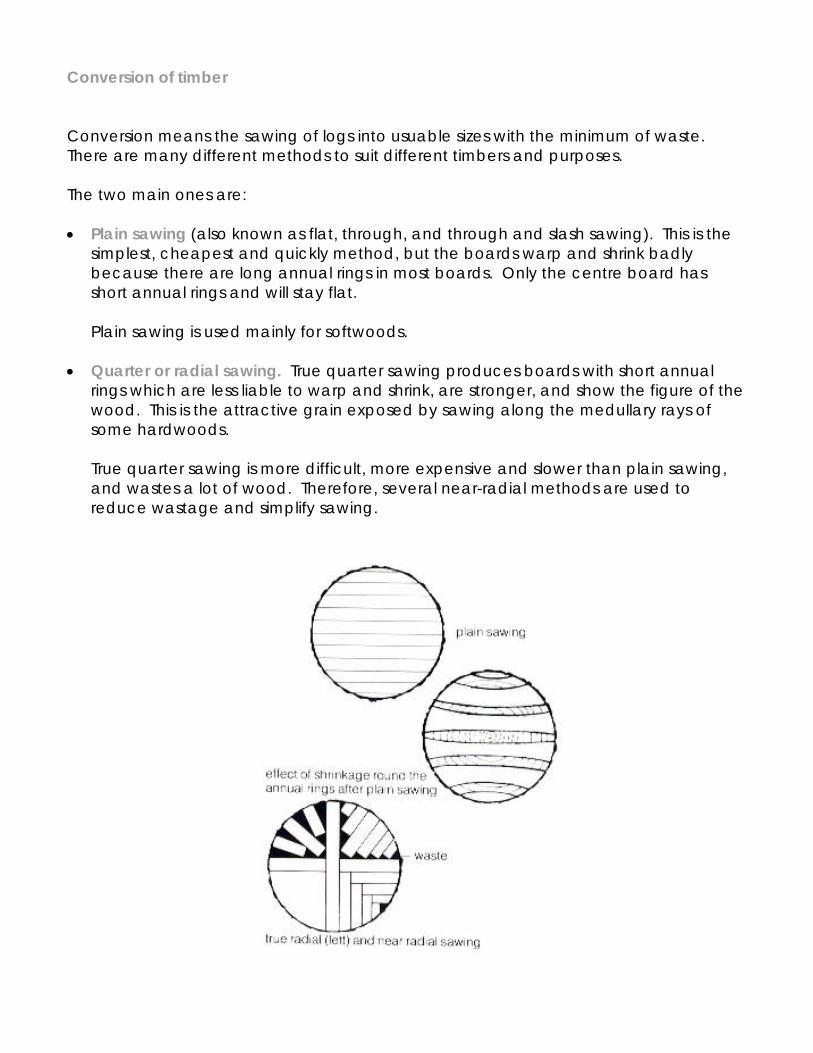
Conversion of timber Conversion means the sawing of logs into usuable sizes with the minimum of waste. There are many different methods to suit different timbers and purposes. The two main ones are: • Plain sawing (also known as flat, through, and through and slash sawing). This is the
simplest, cheapest and quickly method, but the boards warp and shrink badly because there are long annual rings in most boards. Only the centre board has short annual rings and will stay flat.
Plain sawing is used mainly for softwoods.
• Quarter or radial sawing. True quarter sawing produces boards with short annual rings which are less liable to warp and shrink, are stronger, and show the figure of the wood. This is the attractive grain exposed by sawing along the medullary rays of some hardwoods.
True quarter sawing is more difficult, more expensive and slower than plain sawing, and wastes a lot of wood. Therefore, several near-radial methods are used to reduce wastage and simplify sawing.
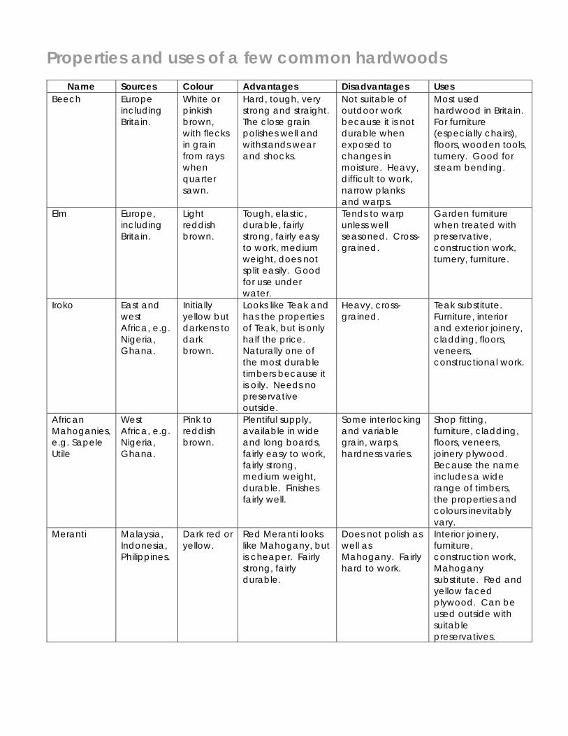
Properties and uses of a few common hardwoods Name Sources Colour Advantages Disadvantages Uses
Beech Europe including Britain.
White or pinkish brown, with flecks in grain from rays when quarter sawn.
Hard, tough, very strong and straight. The close grain polishes well and withstands wear and shocks.
Not suitable of outdoor work because it is not durable when exposed to changes in moisture. Heavy, difficult to work, narrow planks and warps.
Most used hardwood in Britain. For furniture (especially chairs), floors, wooden tools, turnery. Good for steam bending.
Elm Europe, including Britain.
Light reddish brown.
Tough, elastic, durable, fairly strong, fairly easy to work, medium weight, does not split easily. Good for use under water.
Tends to warp unless well seasoned. Cross-grained.
Garden furniture when treated with preservative, construction work, turnery, furniture.
Iroko East and west Africa, e.g. Nigeria, Ghana.
Initially yellow but darkens to dark brown.
Looks like Teak and has the properties of Teak, but is only half the price. Naturally one of the most durable timbers because it is oily. Needs no preservative outside.
Heavy, cross-grained.
Teak substitute. Furniture, interior and exterior joinery, cladding, floors, veneers, constructional work.
African Mahoganies, e.g. Sapele Utile
West Africa, e.g. Nigeria, Ghana.
Pink to reddish brown.
Plentiful supply, available in wide and long boards, fairly easy to work, fairly strong, medium weight, durable. Finishes fairly well.
Some interlocking and variable grain, warps, hardness varies.
Shop fitting, furniture, cladding, floors, veneers, joinery plywood. Because the name includes a wide range of timbers, the properties and colours inevitably vary.
Meranti Malaysia, Indonesia, Philippines.
Dark red or yellow.
Red Meranti looks like Mahogany, but is cheaper. Fairly strong, fairly durable.
Does not polish as well as Mahogany. Fairly hard to work.
Interior joinery, furniture, construction work, Mahogany substitute. Red and yellow faced plywood. Can be used outside with suitable preservatives.
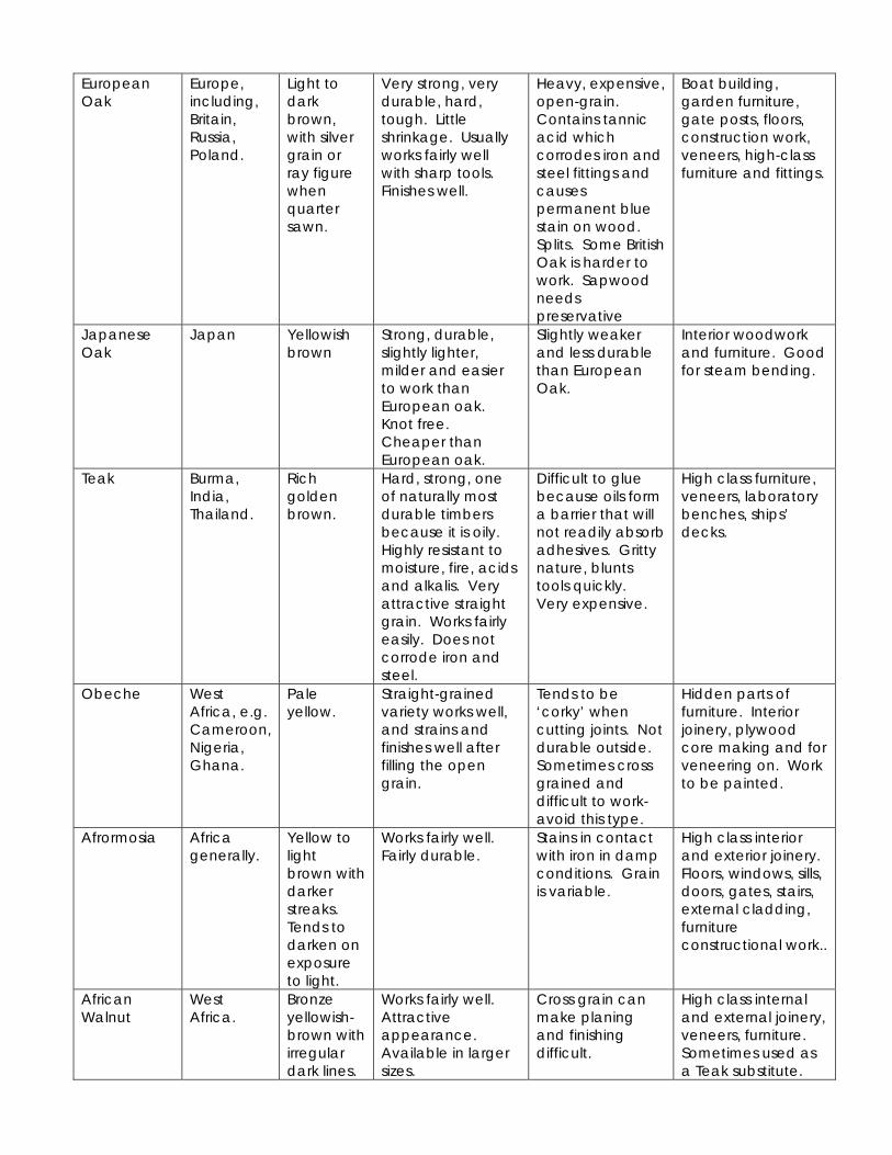
European Oak
Europe, including, Britain, Russia, Poland.
Light to dark brown, with silver grain or ray figure when quarter sawn.
Very strong, very durable, hard, tough. Little shrinkage. Usually works fairly well with sharp tools. Finishes well.
Heavy, expensive, open-grain. Contains tannic acid which corrodes iron and steel fittings and causes permanent blue stain on wood. Splits. Some British Oak is harder to work. Sapwood needs preservative
Boat building, garden furniture, gate posts, floors, construction work, veneers, high-class furniture and fittings.
Japanese Oak
Japan Yellowish brown
Strong, durable, slightly lighter, milder and easier to work than European oak. Knot free. Cheaper than European oak.
Slightly weaker and less durable than European Oak.
Interior woodwork and furniture. Good for steam bending.
Teak Burma, India, Thailand.
Rich golden brown.
Hard, strong, one of naturally most durable timbers because it is oily. Highly resistant to moisture, fire, acids and alkalis. Very attractive straight grain. Works fairly easily. Does not corrode iron and steel.
Difficult to glue because oils form a barrier that will not readily absorb adhesives. Gritty nature, blunts tools quickly. Very expensive.
High class furniture, veneers, laboratory benches, ships’ decks.
Obeche West Africa, e.g. Cameroon, Nigeria, Ghana.
Pale yellow.
Straight-grained variety works well, and strains and finishes well after filling the open grain.
Tends to be ‘corky’ when cutting joints. Not durable outside. Sometimes cross grained and difficult to work-avoid this type.
Hidden parts of furniture. Interior joinery, plywood core making and for veneering on. Work to be painted.
Afrormosia Africa generally.
Yellow to light brown with darker streaks. Tends to darken on exposure to light.
Works fairly well. Fairly durable.
Stains in contact with iron in damp conditions. Grain is variable.
High class interior and exterior joinery. Floors, windows, sills, doors, gates, stairs, external cladding, furniture constructional work..
African Walnut
West Africa.
Bronze yellowish-brown with irregular dark lines.
Works fairly well. Attractive appearance. Available in larger sizes.
Cross grain can make planing and finishing difficult.
High class internal and external joinery, veneers, furniture. Sometimes used as a Teak substitute.
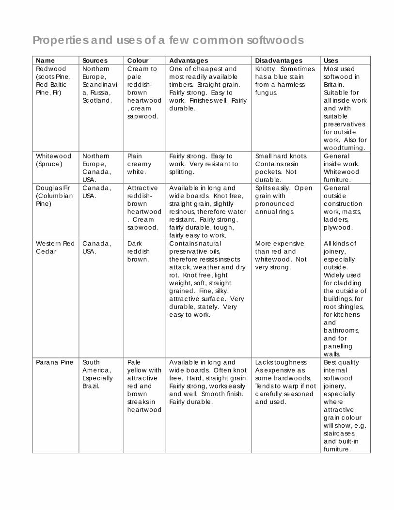
Properties and uses of a few common softwoods Name Sources Colour Advantages Disadvantages Uses Redwood (scots Pine, Red Baltic Pine, Fir)
Northern Europe, Scandinavia, Russia, Scotland.
Cream to pale reddish-brown heartwood, cream sapwood.
One of cheapest and most readily available timbers. Straight grain. Fairly strong. Easy to work. Finishes well. Fairly durable.
Knotty. Sometimes has a blue stain from a harmless fungus.
Most used softwood in Britain. Suitable for all inside work and with suitable preservatives for outside work. Also for woodturning.
Whitewood (Spruce)
Northern Europe, Canada, USA.
Plain creamy white.
Fairly strong. Easy to work. Very resistant to splitting.
Small hard knots. Contains resin pockets. Not durable.
General inside work. Whitewood furniture.
Douglas Fir (Columbian Pine)
Canada, USA.
Attractive reddish-brown heartwood. Cream sapwood.
Available in long and wide boards. Knot free, straight grain, slightly resinous, therefore water resistant. Fairly strong, fairly durable, tough, fairly easy to work.
Splits easily. Open grain with pronounced annual rings.
General outside construction work, masts, ladders, plywood.
Western Red Cedar
Canada, USA.
Dark reddish brown.
Contains natural preservative oils, therefore resists insects attack, weather and dry rot. Knot free, light weight, soft, straight grained. Fine, silky, attractive surface. Very durable, stately. Very easy to work.
More expensive than red and whitewood. Not very strong.
All kinds of joinery, especially outside. Widely used for cladding the outside of buildings, for root shingles, for kitchens and bathrooms, and for panelling walls.
Parana Pine South America, Especially Brazil.
Pale yellow with attractive red and brown streaks in heartwood
Available in long and wide boards. Often knot free. Hard, straight grain. Fairly strong, works easily and well. Smooth finish. Fairly durable.
Lacks toughness. As expensive as some hardwoods. Tends to warp if not carefully seasoned and used.
Best quality internal softwood joinery, especially where attractive grain colour will show, e.g. staircases, and built-in furniture.
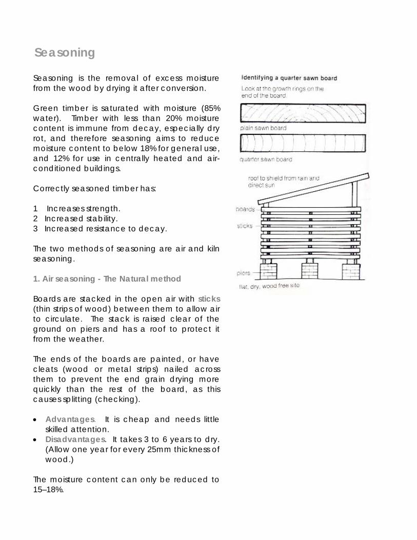
Seasoning
Seasoning is the removal of excess moisture from the wood by drying it after conversion. Green timber is saturated with moisture (85% water). Timber with less than 20% moisture content is immune from decay, especially dry rot, and therefore seasoning aims to reduce moisture content to below 18% for general use, and 12% for use in centrally heated and air-conditioned buildings. Correctly seasoned timber has: 1 Increases strength. 2 Increased stability. 3 Increased resistance to decay. The two methods of seasoning are air and kiln seasoning. 1. Air seasoning - The Natural method Boards are stacked in the open air with sticks (thin strips of wood) between them to allow air to circulate. The stack is raised clear of the ground on piers and has a roof to protect it from the weather. The ends of the boards are painted, or have cleats (wood or metal strips) nailed across them to prevent the end grain drying more quickly than the rest of the board, as this causes splitting (checking). • Advantages. It is cheap and needs little
skilled attention. • Disadvantages. It takes 3 to 6 years to dry.
(Allow one year for every 25mm thickness of wood.)
The moisture content can only be reduced to 15–18%.
Testing moisture content Wood is never completely dry in normal use and moisture content (m.c.) is the amount of water contained in the wood, as a percentage of its oven-dry weight. During seasoning, a sample is usually put in with the main stock and checked at intervals. Method 1 - Weighing (a) Weigh a sample of the wood to be tested (initial weight). (b) Dry it in an oven until there is no further weight loss. (c) Weigh the dry sample (dry weight). (d) Initial weight – dry weight X 100 = %m.c. dry weight
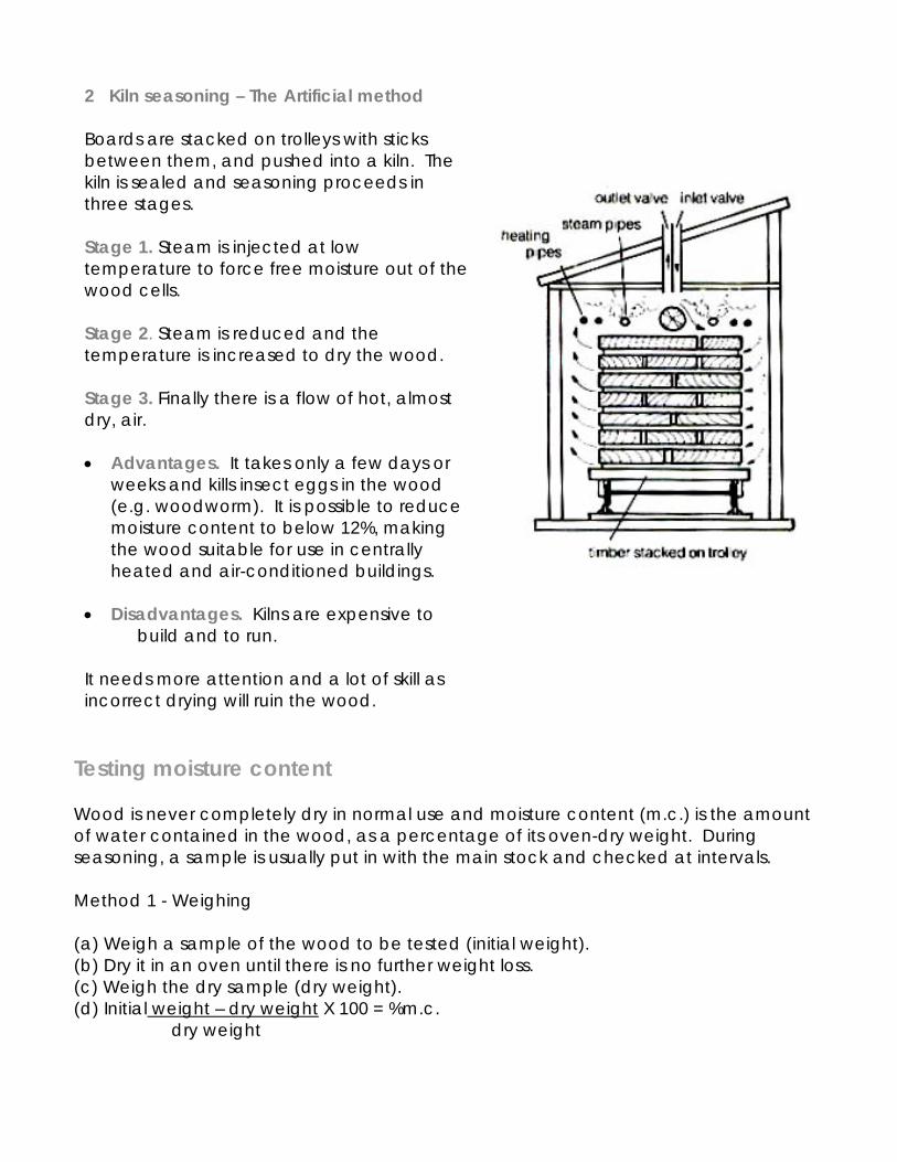
2 Kiln seasoning – The Artificial method Boards are stacked on trolleys with sticks between them, and pushed into a kiln. The kiln is sealed and seasoning proceeds in three stages. Stage 1. Steam is injected at low temperature to force free moisture out of the wood cells. Stage 2. Steam is reduced and the temperature is increased to dry the wood. Stage 3. Finally there is a flow of hot, almost dry, air. • Advantages. It takes only a few days or
weeks and kills insect eggs in the wood (e.g. woodworm). It is possible to reduce moisture content to below 12%, making the wood suitable for use in centrally heated and air-conditioned buildings.
• Disadvantages. Kilns are expensive to
build and to run. It needs more attention and a lot of skill as incorrect drying will ruin the wood.
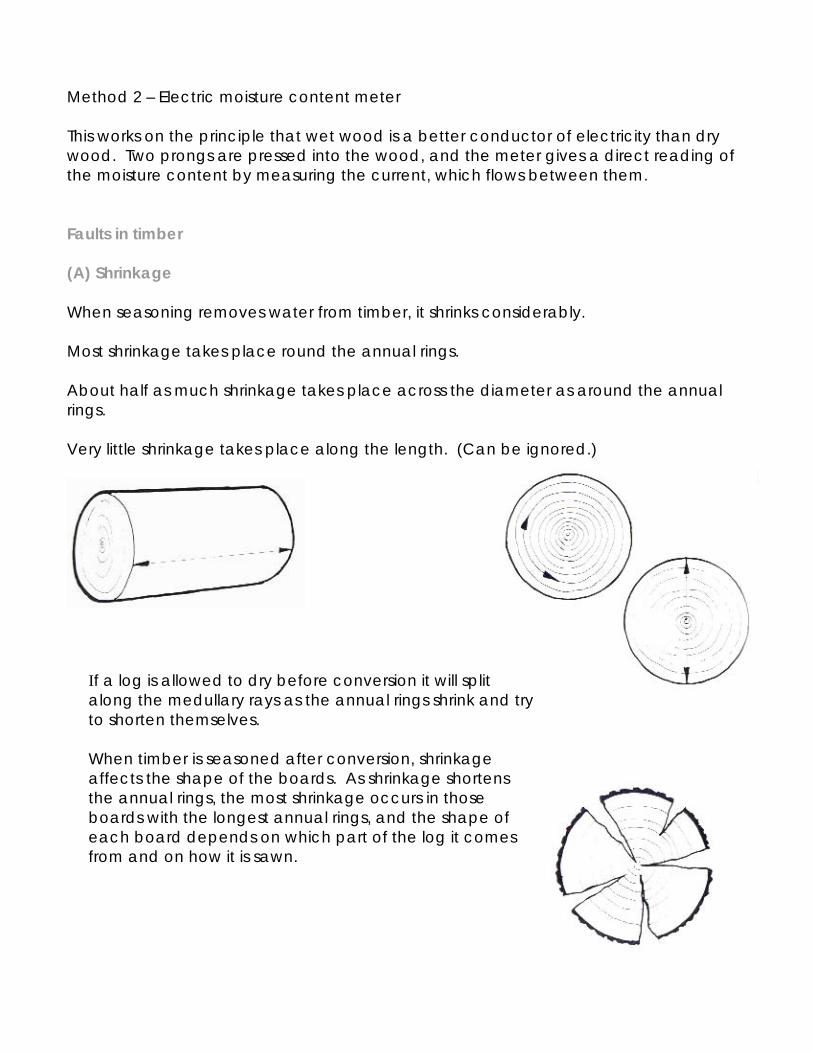
Method 2 – Electric moisture content meter This works on the principle that wet wood is a better conductor of electricity than dry wood. Two prongs are pressed into the wood, and the meter gives a direct reading of the moisture content by measuring the current, which flows between them. Faults in timber (A) Shrinkage When seasoning removes water from timber, it shrinks considerably. Most shrinkage takes place round the annual rings. About half as much shrinkage takes place across the diameter as around the annual rings. Very little shrinkage takes place along the length. (Can be ignored.)
If a log is allowed to dry before conversion it will split along the medullary rays as the annual rings shrink and try to shorten themselves. When timber is seasoned after conversion, shrinkage affects the shape of the boards. As shrinkage shortens the annual rings, the most shrinkage occurs in those boards with the longest annual rings, and the shape of each board depends on which part of the log it comes from and on how it is sawn.
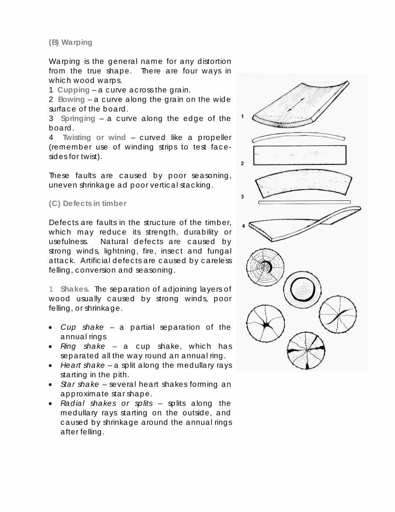
(B) Warping Warping is the general name for any distortion from the true shape. There are four ways in which wood warps. 1 Cupping – a curve across the grain. 2 Bowing – a curve along the grain on the wide surface of the board. 3 Springing – a curve along the edge of the board. 4 Twisting or wind – curved like a propeller (remember use of winding strips to test face-sides for twist). These faults are caused by poor seasoning, uneven shrinkage ad poor vertical stacking. (C) Defects in timber Defects are faults in the structure of the timber, which may reduce its strength, durability or usefulness. Natural defects are caused by strong winds, lightning, fire, insect and fungal attack. Artificial defects are caused by careless felling, conversion and seasoning. 1 Shakes. The separation of adjoining layers of wood usually caused by strong winds, poor felling, or shrinkage. • Cup shake – a partial separation of the
annual rings • Ring shake – a cup shake, which has
separated all the way round an annual ring. • Heart shake – a split along the medullary rays
starting in the pith. • Star shake – several heart shakes forming an
approximate star shape. • Radial shakes or splits – splits along the
medullary rays starting on the outside, and caused by shrinkage around the annual rings after felling.
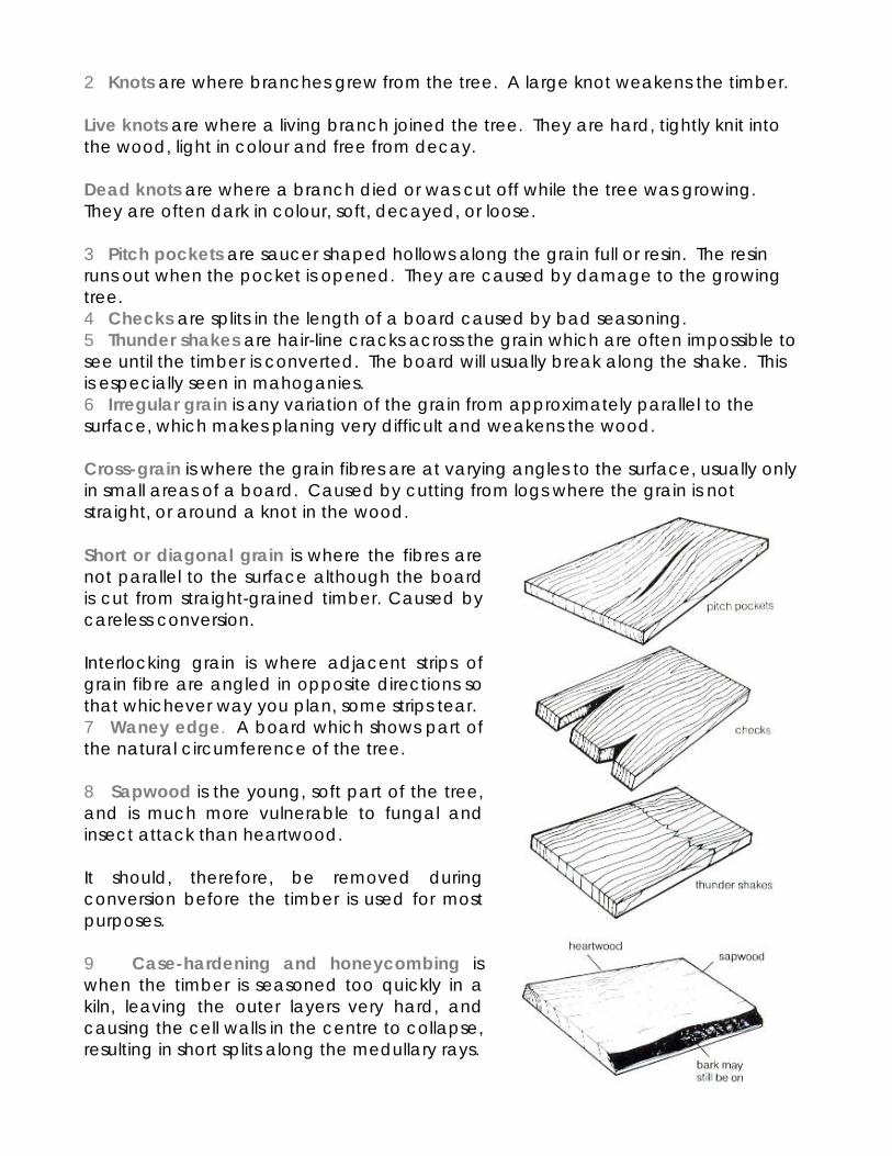
2 Knots are where branches grew from the tree. A large knot weakens the timber. Live knots are where a living branch joined the tree. They are hard, tightly knit into the wood, light in colour and free from decay. Dead knots are where a branch died or was cut off while the tree was growing. They are often dark in colour, soft, decayed, or loose. 3 Pitch pockets are saucer shaped hollows along the grain full or resin. The resin runs out when the pocket is opened. They are caused by damage to the growing tree. 4 Checks are splits in the length of a board caused by bad seasoning. 5 Thunder shakes are hair-line cracks across the grain which are often impossible to see until the timber is converted. The board will usually break along the shake. This is especially seen in mahoganies. 6 Irregular grain is any variation of the grain from approximately parallel to the surface, which makes planing very difficult and weakens the wood. Cross-grain is where the grain fibres are at varying angles to the surface, usually only in small areas of a board. Caused by cutting from logs where the grain is not straight, or around a knot in the wood.
Short or diagonal grain is where the fibres are not parallel to the surface although the board is cut from straight-grained timber. Caused by careless conversion. Interlocking grain is where adjacent strips of grain fibre are angled in opposite directions so that whichever way you plan, some strips tear. 7 Waney edge. A board which shows part of the natural circumference of the tree. 8 Sapwood is the young, soft part of the tree, and is much more vulnerable to fungal and insect attack than heartwood. It should, therefore, be removed during conversion before the timber is used for most purposes. 9 Case-hardening and honeycombing is when the timber is seasoned too quickly in a kiln, leaving the outer layers very hard, and causing the cell walls in the centre to collapse, resulting in short splits along the medullary rays.
(D) Insect attack Most insect damage to wood in Britain is caused by beetles. They all have a similar four-stage life cycle, and the tree most important are furniture beetle (commonly called woodworm), death-watch beetle, and powder post beetle (lyctus). The life cycle 1 Eggs are laid by beetles in cracks in timber. 2 Eggs hatch into larvae which bore into the wood, and feed on it for 1-50- years. 3 When full grown, the larvae hollow out tiny caverns just below the surface and grow into pupae. 4 Pupae hatch into beetles and bite their way out of the wood through the flight holes which we see in infested timber, mate, and restart the cycle. The infestation is not visible until the flight holes appear, by which time it may be too late. Furniture beetle This attacks hardwood, softwood and some plywoods, especially sapwood and old wood, and is responsible for 75% of known damage to timber in buildings. It produces pellets of coarse, gritty powder, and honeycombs the inside of the timber with tunnels. Death watch beetle This attacks hardwoods, especially old oak structural timbers, and occasionally softwood, usually where there is also damp ad fungal attack (see section E). it is not normally found in houses or furniture and produces bun-like pellets of coarse dust which are easily seen. Powder post beetle This attacks only the sapwood of hardwoods. It reduces the inside of the timber to a very fine powder and produces flour-like bore dust. Prevention 1 Apply preservative to timber, e.g. creosote or insecticides. 2 Keep furniture clean and wax polished to seal small cracks.
Treatment 1 In a building, cut-out and burn infested timber wherever possible. This may not be possible when repairing furniture. 2 Apply a deep penetrating insecticide to kill larvae and give protection from renewed attacked. 3 Fill old holes with stopper so that new holes can be spotted. Treatment of serious infestation requires expert help. (E) Fungal attack All fungi which attack timber develop under similar conditions. They require: 1 Food. The cells of non-durable wood, especially sapwood. 2 Moisture. The moisture content of the wood must be at least 20% (see Seasoning). 3 Oxygen from the air. 4 Correct temperature. Unfortunately the temperature in Britain is never too hot or too cold for fungus. 5 Lack of air circulation. Decay can be recognized by: 1 Softening and change of colour of the wood. 2 Loss of weight of wood. 3 A musty smell. The main types of fungal attack are wet rot and dry rot. Wet rot (or white rot) This is a general name for a group of fungi, which attack timber with 30% or more moisture content. It is the commonest form of rot, especially on outside woodwork. The wood becomes dark and spongy when wet, and brittle when dry.
Plastics The manufacture of plastics Plastics are man-made materials. They are distinguished from other chemical compounds by the large size of their molecules. While most substances have molecules made up of less than 300 atoms, plastics molecules contain thousands of atoms. They are therefore known as macromolecules. Sources of Plastics A few plastics are made by modifying natural substances which already have large molecules but most of those used today are man-made and are therefore known as synthetic plastics Animals: Horn Insects: Lac – Shellac (French polish) Milk - Casein (glue)
- Formaldehyde (glue) Plants: Cellulose – celluloid (table tennis balls)
cellulose acetate (cloth, photographic film, handles) cellophane (wrapping) Bitumen (roads, flat roofs) Latex (rubber)
Trees: Bitumen (roads, flat roofs) Latex (rubber) Gutta Percha (golf ball casings) Rosin – resin (paint) Amber (semi-precious decoration) The main source of synthetic plastics is crude oil, but coal and natural gas are also used. During the refining of crude oil, liquids of various densities, such as petrol, paraffin and lubricating oils and highly volatile petroleum gases are produced. These gases form the basis of the plastics industry. Although complex and expensive equipment is needed to manufacture plastics, the basic process is simple. The gases are broken down into monomers, which are chemical substances consisting of a single molecule and thousands of these are then linked together in a process called polymerization to form new compounds called polymers. Most polymers are made by combining the element carbon with one or more of the elements oxygen, hydrogen, chlorine, fluorine and nitrogen
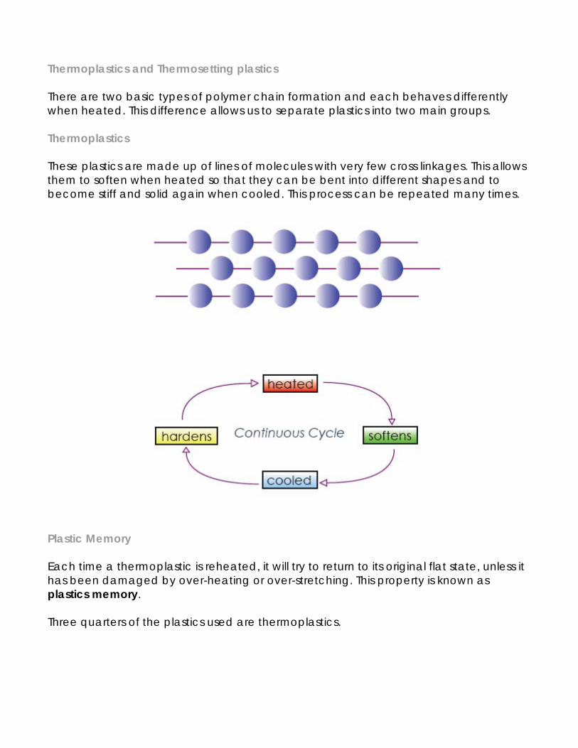
Thermoplastics and Thermosetting plastics There are two basic types of polymer chain formation and each behaves differently when heated. This difference allows us to separate plastics into two main groups. Thermoplastics These plastics are made up of lines of molecules with very few cross linkages. This allows them to soften when heated so that they can be bent into different shapes and to become stiff and solid again when cooled. This process can be repeated many times.
Plastic Memory Each time a thermoplastic is reheated, it will try to return to its original flat state, unless it has been damaged by over-heating or over-stretching. This property is known as plastics memory. Three quarters of the plastics used are thermoplastics.
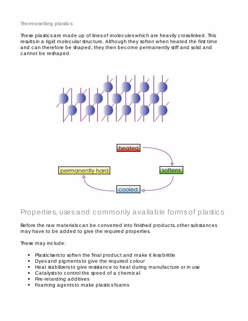
Thermosetting plastics These plastics are made up of lines of molecules which are heavily cross-linked. This results in a rigid molecular structure. Although they soften when heated the first time and can therefore be shaped, they then become permanently stiff and solid and cannot be reshaped.
Properties, uses and commonly available forms of plastics Before the raw materials can be converted into finished products, other substances may have to be added to give the required properties. These may include:
Plasticisers to soften the final product and make it less brittle Dyes and pigments to give the required colour Heat stabilizers to give resistance to heat during manufacture or in use Catalysts to control the speed of a chemical Fire-retarding additives Foaming agents to make plastics foams
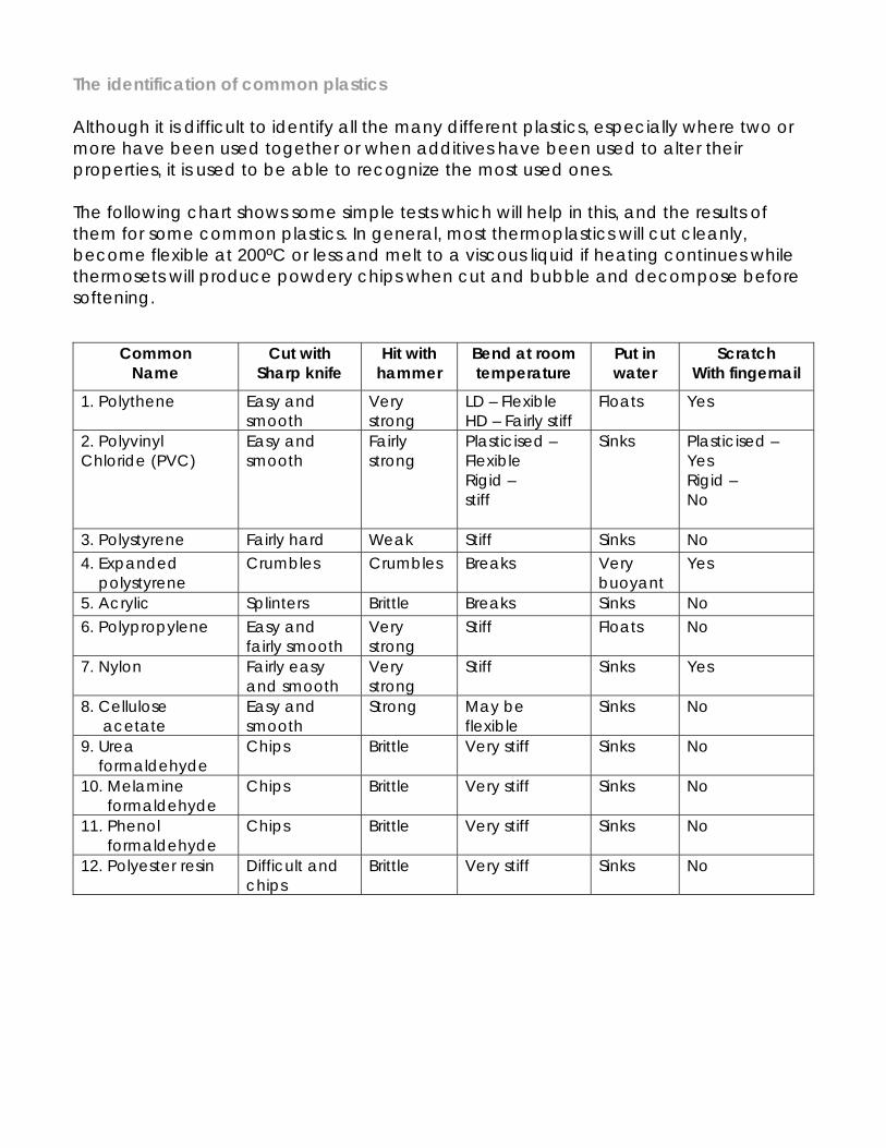
The identification of common plastics Although it is difficult to identify all the many different plastics, especially where two or more have been used together or when additives have been used to alter their properties, it is used to be able to recognize the most used ones. The following chart shows some simple tests which will help in this, and the results of them for some common plastics. In general, most thermoplastics will cut cleanly, become flexible at 200ºC or less and melt to a viscous liquid if heating continues while thermosets will produce powdery chips when cut and bubble and decompose before softening.
Common Name
Cut with Sharp knife
Hit with hammer
Bend at room temperature
Put in water
Scratch With fingernail
1. Polythene Easy and smooth
Very strong
LD – Flexible HD – Fairly stiff
Floats Yes
2. Polyvinyl Chloride (PVC)
Easy and smooth
Fairly strong
Plasticised – Flexible Rigid – stiff
Sinks Plasticised – Yes Rigid – No
3. Polystyrene Fairly hard Weak Stiff Sinks No 4. Expanded polystyrene
Crumbles Crumbles Breaks Very buoyant
Yes
5. Acrylic Splinters Brittle Breaks Sinks No 6. Polypropylene Easy and
fairly smooth Very strong
Stiff Floats No
7. Nylon Fairly easy and smooth
Very strong
Stiff Sinks Yes
8. Cellulose acetate
Easy and smooth
Strong May be flexible
Sinks No
9. Urea formaldehyde
Chips Brittle Very stiff Sinks No
10. Melamine formaldehyde
Chips Brittle Very stiff Sinks No
11. Phenol formaldehyde
Chips Brittle Very stiff Sinks No
12. Polyester resin Difficult and chips
Brittle Very stiff Sinks No
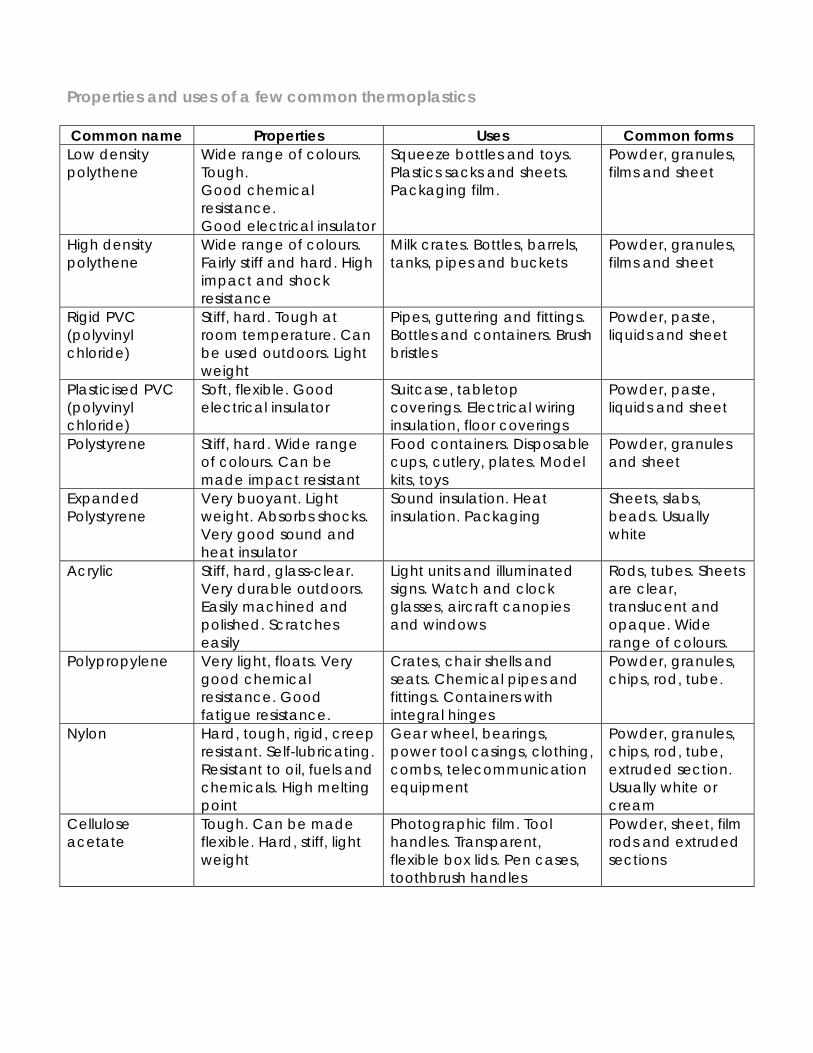
Properties and uses of a few common thermoplastics Common name Properties Uses Common forms Low density polythene
Wide range of colours. Tough. Good chemical resistance. Good electrical insulator
Squeeze bottles and toys. Plastics sacks and sheets. Packaging film.
Powder, granules, films and sheet
High density polythene
Wide range of colours. Fairly stiff and hard. High impact and shock resistance
Milk crates. Bottles, barrels, tanks, pipes and buckets
Powder, granules, films and sheet
Rigid PVC (polyvinyl chloride)
Stiff, hard. Tough at room temperature. Can be used outdoors. Light weight
Pipes, guttering and fittings. Bottles and containers. Brush bristles
Powder, paste, liquids and sheet
Plasticised PVC (polyvinyl chloride)
Soft, flexible. Good electrical insulator
Suitcase, tabletop coverings. Electrical wiring insulation, floor coverings
Powder, paste, liquids and sheet
Polystyrene Stiff, hard. Wide range of colours. Can be made impact resistant
Food containers. Disposable cups, cutlery, plates. Model kits, toys
Powder, granules and sheet
Expanded Polystyrene
Very buoyant. Light weight. Absorbs shocks. Very good sound and heat insulator
Sound insulation. Heat insulation. Packaging
Sheets, slabs, beads. Usually white
Acrylic Stiff, hard, glass-clear. Very durable outdoors. Easily machined and polished. Scratches easily
Light units and illuminated signs. Watch and clock glasses, aircraft canopies and windows
Rods, tubes. Sheets are clear, translucent and opaque. Wide range of colours.
Polypropylene Very light, floats. Very good chemical resistance. Good fatigue resistance.
Crates, chair shells and seats. Chemical pipes and fittings. Containers with integral hinges
Powder, granules, chips, rod, tube.
Nylon Hard, tough, rigid, creep resistant. Self-lubricating. Resistant to oil, fuels and chemicals. High melting point
Gear wheel, bearings, power tool casings, clothing, combs, telecommunication equipment
Powder, granules, chips, rod, tube, extruded section. Usually white or cream
Cellulose acetate
Tough. Can be made flexible. Hard, stiff, light weight
Photographic film. Tool handles. Transparent, flexible box lids. Pen cases, toothbrush handles
Powder, sheet, film rods and extruded sections
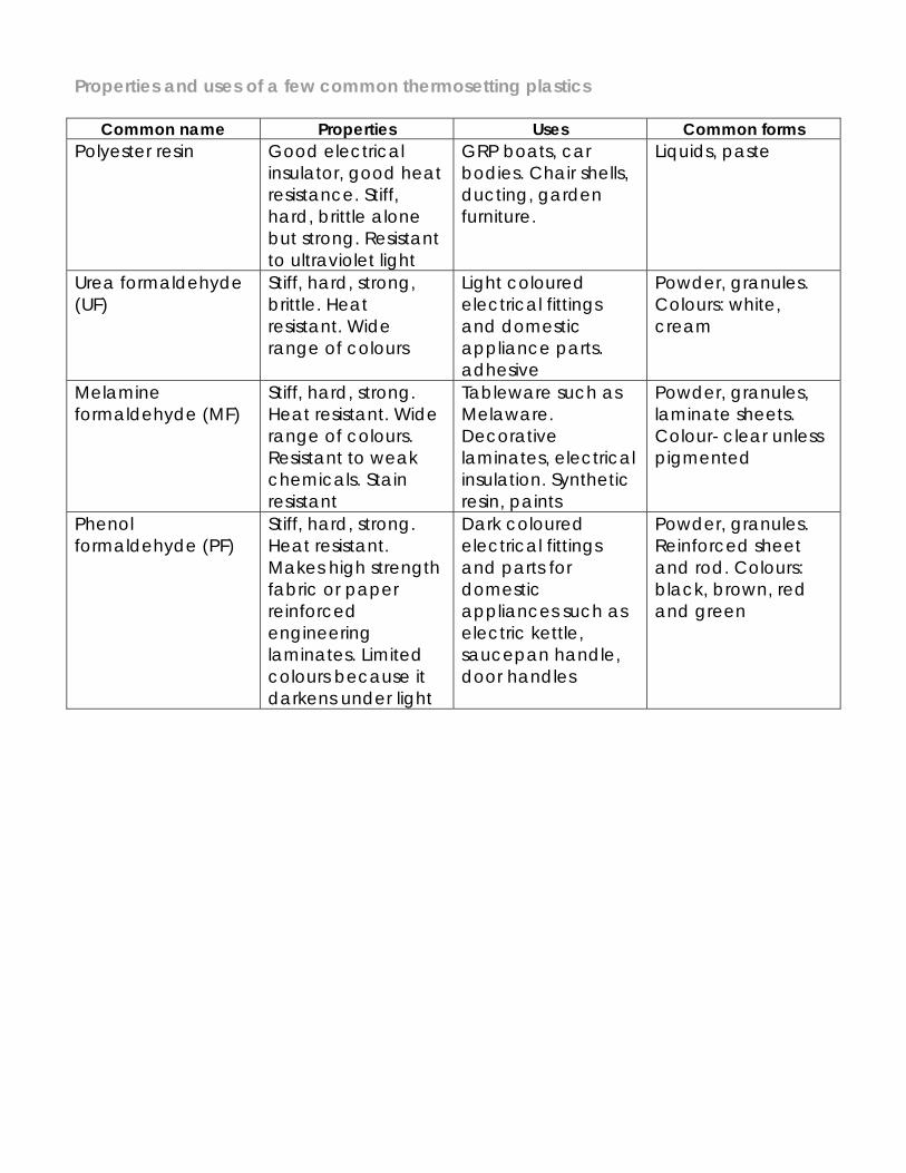
Properties and uses of a few common thermosetting plastics
Common name Properties Uses Common forms Polyester resin Good electrical
insulator, good heat resistance. Stiff, hard, brittle alone but strong. Resistant to ultraviolet light
GRP boats, car bodies. Chair shells, ducting, garden furniture.
Liquids, paste
Urea formaldehyde (UF)
Stiff, hard, strong, brittle. Heat resistant. Wide range of colours
Light coloured electrical fittings and domestic appliance parts. adhesive
Powder, granules. Colours: white, cream
Melamine formaldehyde (MF)
Stiff, hard, strong. Heat resistant. Wide range of colours. Resistant to weak chemicals. Stain resistant
Tableware such as Melaware. Decorative laminates, electrical insulation. Synthetic resin, paints
Powder, granules, laminate sheets. Colour- clear unless pigmented
Phenol formaldehyde (PF)
Stiff, hard, strong. Heat resistant. Makes high strength fabric or paper reinforced engineering laminates. Limited colours because it darkens under light
Dark coloured electrical fittings and parts for domestic appliances such as electric kettle, saucepan handle, door handles
Powder, granules. Reinforced sheet and rod. Colours: black, brown, red and green
Cleaning-up and finishing plastics The following instructions apply particularly to acrylic but will be found suitable for most hard plastics. Take care to avoid scratching the surface of plastics at all times. Leave the protective paper covering on, where supplied, for as long as possible. After removing the paper the last traces of adhesive can be washed off with warm, soapy water. Stage 1 After cutting, plane, file or sand the edges to remove saw marks. If using a disc or belt sander on thermoplastics, use a coarse abrasive and light pressure to avoid overheating. If filling, finish by draw filing. Stage 2 Use a scraper or wet and dry paper, to obtain a completely smooth edge. Scraping will leave the edges ready for machine polishing. By using progressively finer grades of wet and dry paper, the edges can be made ready for hand finishing. Use the wet and dry paper on a cork block to keep the edges square. Stage 3 To avoid overheating when machine polishing thermoplastics, keep the work moving, lightly against a soft mop coated with a mild abrasive. When hand polishing use progressively finer grades of abrasive polish. Domestic metal polish is a fine finishing abrasive Deep surface scratches can be removed from most plastics by using progressively finer grades of wet and dry paper or rubbing down compound. Wet and dry paper (silicone carbide paper) is graded by grit sizes. Common grades are: 60-120 grit coarse 200-300 grit medium 400-600 grit fine 800-2000 grit super fine
Metal Metals make up a major portion of all the naturally occurring elements and form about a quarter of the Earth’s crust by weight. All metals, with the exception of gold, are found chemically combined with other elements in the form of oxides and sulphates. The production of iron Iron ore, usually in the form of iron oxide in rocks, is mined or quarried and taken to a steelworks. There it is graded and crushed to reduce it to a maximum size of 100mm cubes. Small particles are mixed with coke and heated to form a clinker of similar size called sinter. Once lit, a blast furnace runs continuously until the heat-resistant bricks of the refractory lining start to burn away, usually after about 2 years. The raw materials, coke, limestone, iron-ore and sinter are continuously poured in through the double bell charging system which prevents hot gases from escaping during charging Heated air is blasted into the bottom of the furnace from the blast or bustle pipe through the tuyères, to make the coke burn effectively. The iron in the ore melts and collects in the well at the bottom of the furnace. The limestone acts as a flux to make impurities float on the surface of the molten iron in the form of a liquid slag, which can be tapped off. The iron and slag are tapped off at regular intervals. The hot waste gases go through a gas cleaning plant before either being reused to heat the blast to 800ºC or being burnt off. The iron produced is 90 to 95% pure and it is used in one of three ways.
1. In a modern integrated steel works it is conveyed in its molten state straight to the steel-making furnaces.
2. It is fed into a pig casting machine which makes it into small iron bars (pig iron) for future remelting, for example, in an electric arc furnace.
3. It is refined into cast iron which is a strong but brittle metal especially suitable for making intricate castings such as engine cylinder blocks and cylinder heads simply, easily and economically.
The production of steel The raw materials for steel making are iron from the blast furnaces, scrap iron and steel. The amount of each used depends on the type of steel being made and the process used. Because there are many different types of steel, for example, mild steel, tool steels, stainless steel and steel alloys, there are many variations in the techniques used. All steel making however, involves removing impurities and excess carbon from the iron and adding small of other elements. The basic oxygen furnace The furnace is tilted and charged with 30% scrap and then with 70% molten iron. With the furnace upright, a water-cooled oxygen lance is lowered to just above the surface of the metal and oxygen is blown into the melt at very high speed. It combines with carbon and other unwanted elements to remove them from the charge. During the blow, lime is added as a flux so that the oxidized impurities form a slag on the surface ready for tapping off later. After the blow, the steel which has been made is tapped out through the tap hole into a ladle. The converter is then tipped upside down to empty out the slag. Ferrous and Non-Ferrous metals All metals belong to one of these two groups
Ferrous metals are those which are made mainly of iron with small amounts of other metals or other elements added to give the required properties. Almost all ferrous metals can be picked up with a magnet
Non-ferrous metals are those which do not contain iron, for example, aluminium,
copper, lead, zinc and tin. Pure metals and Alloys All metals are also either pure metals or alloys
A pure metal consists of a single element which means that it is a substance having only one type of atom in it. The common pure metals are aluminium, copper, iron, lead, zinc, tin, silver and gold
An alloy is a mixture of two or more pure metals or one or more pure metals
mixed with other elements. Alloys are made in order to create materials which have combinations of properties not available in the pure metals and to fulfil needs for which no pure metal is suitable.
The heat treatment of metals Heat treatment is a way of making metals more suitable for processing or for the jobs which they have to do. For example, a piece of high carbon steel being used to make a cold chisel must be annealed (softened), so that it can be shaped, and then hardened and tempered so that it can cut other metals. There are three stages in heat treatment:
1. Heat the metal to the correct temperature 2. Keep it at that temperature for the required length of time (soaking) 3. Cool it in the correct way to give the desired properties.
Annealing makes the metal as soft as possible to relieve internal stresses, and to make it easier to shape.
Mild Steel is heated to bright red heat, soaked for a short time and left to cool slowly.
Aluminium is covered with soap, heated gently until the soap turns black and left
to cool Tool Steel is heated to bright red heat, soaked for a short time and left to cool
very slowly in hot ashes. The more slowly the metal cools, the softer it will be.
Normalising returns work hardened steel to its normal condition after forging or previous heat treatment. Steel is heated to red hot and left to cool. Hardening increases the hardness and tensile strength of tool steel in order to make cutting tools, springs, etc. Hardening can only be carried out on carbon and alloy steels. The higher the carbon content of the steel, the harder it will be.
Steel is heated to cherry red heat, soaked for a short time and quenched vertically in oil, brine or tepid water. Quenching horizontally or in cold water can cause cracking. Hardened metal is brittle and unusable.
Case Hardening is a method of putting a hard surface coating onto steels which do not contain enough carbon for hardening and tempering. Carbon is burnt into the surface of the metal so that it can be hardened to give a wear resistant shell and a tough break resistant core.
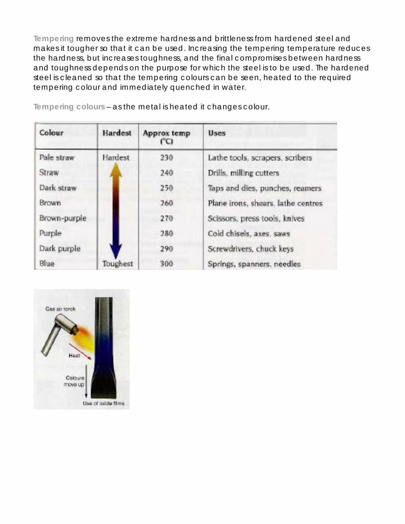
Tempering removes the extreme hardness and brittleness from hardened steel and makes it tougher so that it can be used. Increasing the tempering temperature reduces the hardness, but increases toughness, and the final compromises between hardness and toughness depends on the purpose for which the steel is to be used. The hardened steel is cleaned so that the tempering colours can be seen, heated to the required tempering colour and immediately quenched in water. Tempering colours – as the metal is heated it changes colour.
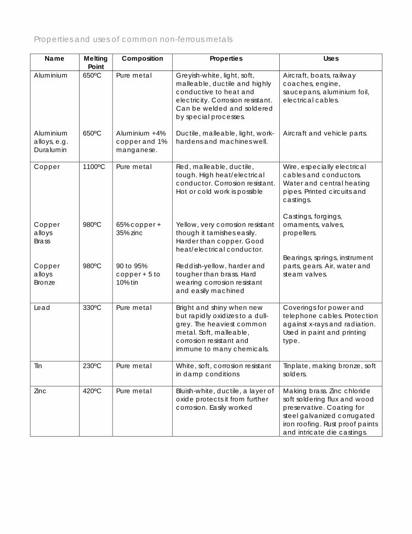
Properties and uses of common non-ferrous metals
Name Melting Point
Composition Properties Uses
Aluminium Aluminium alloys, e.g. Duralumin
650ºC 650ºC
Pure metal Aluminium +4% copper and 1% manganese.
Greyish-white, light, soft, malleable, ductile and highly conductive to heat and electricity. Corrosion resistant. Can be welded and soldered by special processes. Ductile, malleable, light, work-hardens and machines well.
Aircraft, boats, railway coaches, engine, saucepans, aluminium foil, electrical cables. Aircraft and vehicle parts.
Copper Copper alloys Brass Copper alloys Bronze
1100ºC 980ºC 980ºC
Pure metal 65% copper + 35% zinc 90 to 95% copper + 5 to 10% tin
Red, malleable, ductile, tough. High heat/electrical conductor. Corrosion resistant. Hot or cold work is possible Yellow, very corrosion resistant though it tarnishes easily. Harder than copper. Good heat/electrical conductor. Reddish-yellow, harder and tougher than brass. Hard wearing corrosion resistant and easily machined
Wire, especially electrical cables and conductors. Water and central heating pipes. Printed circuits and castings. Castings, forgings, ornaments, valves, propellers. Bearings, springs, instrument parts, gears. Air, water and steam valves.
Lead 330ºC Pure metal Bright and shiny when new but rapidly oxidizes to a dull-grey. The heaviest common metal. Soft, malleable, corrosion resistant and immune to many chemicals.
Coverings for power and telephone cables. Protection against x-rays and radiation. Used in paint and printing type.
Tin 230ºC Pure metal White, soft, corrosion resistant in damp conditions
Tinplate, making bronze, soft solders.
Zinc 420ºC Pure metal Bluish-white, ductile, a layer of oxide protects it from further corrosion. Easily worked
Making brass. Zinc chloride soft soldering flux and wood preservative. Coating for steel galvanized corrugated iron roofing. Rust proof paints and intricate die castings.
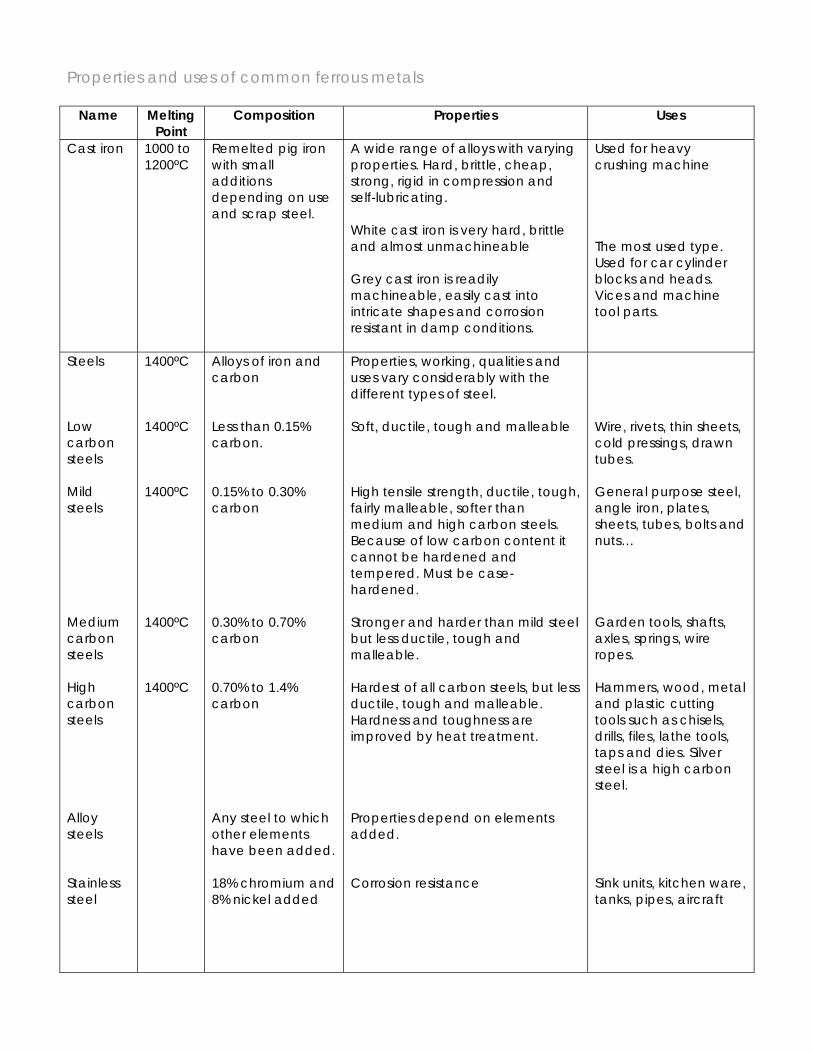
Properties and uses of common ferrous metals
Name Melting Point
Composition Properties Uses
Cast iron 1000 to 1200ºC
Remelted pig iron with small additions depending on use and scrap steel.
A wide range of alloys with varying properties. Hard, brittle, cheap, strong, rigid in compression and self-lubricating. White cast iron is very hard, brittle and almost unmachineable Grey cast iron is readily machineable, easily cast into intricate shapes and corrosion resistant in damp conditions.
Used for heavy crushing machine The most used type. Used for car cylinder blocks and heads. Vices and machine tool parts.
Steels Low carbon steels Mild steels Medium carbon steels High carbon steels Alloy steels Stainless steel
1400ºC 1400ºC 1400ºC 1400ºC 1400ºC
Alloys of iron and carbon Less than 0.15% carbon. 0.15% to 0.30% carbon 0.30% to 0.70% carbon 0.70% to 1.4% carbon Any steel to which other elements have been added. 18% chromium and 8% nickel added
Properties, working, qualities and uses vary considerably with the different types of steel. Soft, ductile, tough and malleable High tensile strength, ductile, tough, fairly malleable, softer than medium and high carbon steels. Because of low carbon content it cannot be hardened and tempered. Must be case-hardened. Stronger and harder than mild steel but less ductile, tough and malleable. Hardest of all carbon steels, but less ductile, tough and malleable. Hardness and toughness are improved by heat treatment. Properties depend on elements added. Corrosion resistance
Wire, rivets, thin sheets, cold pressings, drawn tubes. General purpose steel, angle iron, plates, sheets, tubes, bolts and nuts… Garden tools, shafts, axles, springs, wire ropes. Hammers, wood, metal and plastic cutting tools such as chisels, drills, files, lathe tools, taps and dies. Silver steel is a high carbon steel. Sink units, kitchen ware, tanks, pipes, aircraft

High speed steel High tensile steel
medium carbon steel, tungsten, chromium and vanadium low carbon steel, nickel and chromium
Retains hardness at high temperatures. Brittle. Can be hardened and tempered Exceptional strength and toughness
Cutting tools for lathes Gears, shafts, engine parts
Commonly available forms Metals can be bought in a wide range of shapes and sizes and you should always try to design jobs which use these standard sections. It is advisable to check what materials are in stock before starting or to look in a stockholder’s catalogue to find out what is available. The following sketches show the common shapes and some of the most used sections.
Round rod – 5, 6, 8,10,12,16, 20, 25, 32, 40, 50mm diameter. Squares - 5, 6, 8,10,12,16, 20, 25mm square
Flats – 12 x 1.5mm 20 x 1.5mm 25 x 1.5mm
12 x 3mm 20 x 3mm 25 x 3mm 32 x 3mm 40 x 3mm 50 x 3mm 12 x 6mm 20 x 6mm 25 x 6mm 32 x 6mm 40 x 6mm 50 x 6mm
Hexagons - 6, 8,10,12,16, 20, 22, 25mm across flats.
Octagons - 6, 8,10,12,16, 20, 22, 25mm across flats.
Sheets – 0.6, 0.8, 1.00, 1.2, 1.6, 2.0, 2.5, 3mm thick
Round tubes - 5, 6, 8,10,12,16, 20, 25, 32, 40mm outside diameter
Square tubes - 6, 8,10,12,16, 20, 25, 32, 40, 50mm square
Rectangular tubes – 50 x 30mm
Angles – 12 x 12mm, 18 x 18mm, 25 x 25mm.
Cleaning-up and finishing metal
Painting metal
Stage 1 Thoroughly clean and degrease the metal. Paraffin or special degreasers will clean badly affected parts while hot water with soda or detergent will remove light oil and dirt Stage 2 Find a dust-free place to work and make arrangements for supporting the work while painting and drying before starting. Stage 3 For maximum protection apply primer, undercoat and topcoat. For inside work, one or two coats alone are adequate. Do not allow the paint to collect in corners or run. Paint awkward parts first and then larger, flat, more noticeable areas. Two thin coats are always better than one thick one. Keep brushes clean and paint tin lids sealed. Cleaning Copper and Brass Stage1 Dip into an acid pickle consisting of one part sulphuric acid to ten parts water. Always use brass tongs as steel will contaminate the pickle. Stage 2 Clean the metal with pumice powder and a damp cloth and then remove any blemishes with wetted water of Ayr stone. Stage 3 Finally polish on a polishing machine with a linen mop and Tripoli buffing compound and or by hand using metal polish. Lacquering Stage 1 Thoroughly clean, polish and degrease the metal. Stage 2 Apply the lacquer or varnish with a best quality soft paint brush or spray gun to preserve the finish.
IGCSE Resistant Material
Topic: Hand tools
Student Name: Tutor Group:
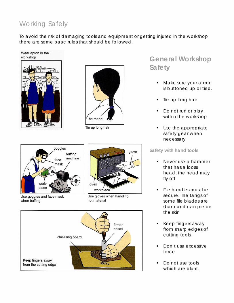
Working Safely To avoid the risk of damaging tools and equipment or getting injured in the workshop there are some basic rules that should be followed.
General Workshop Safety
Make sure your apron is buttoned up or tied.
Tie up long hair
Do not run or play
within the workshop
Use the appropriate safety gear when necessary
Safety with hand tools
Never use a hammer that has a loose head; the head may fly off
File handles must be
secure. The tangs of some file blades are sharp and can pierce the skin
Keep fingers away
from sharp edges of cutting tools.
Don’t use excessive
force
Do not use tools which are blunt.
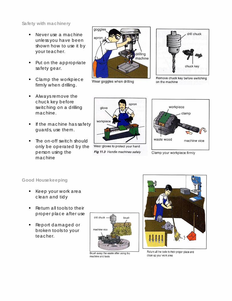
Safety with machinery
Never use a machine unless you have been shown how to use it by your teacher.
Put on the appropriate
safety gear.
Clamp the workpiece firmly when drilling.
Always remove the
chuck key before switching on a drilling machine.
If the machine has safety
guards, use them.
The on-off switch should only be operated by the person using the machine
Good Housekeeping
Keep your work area clean and tidy
Return all tools to their
proper place after use
Report damaged or broken tools to your teacher.
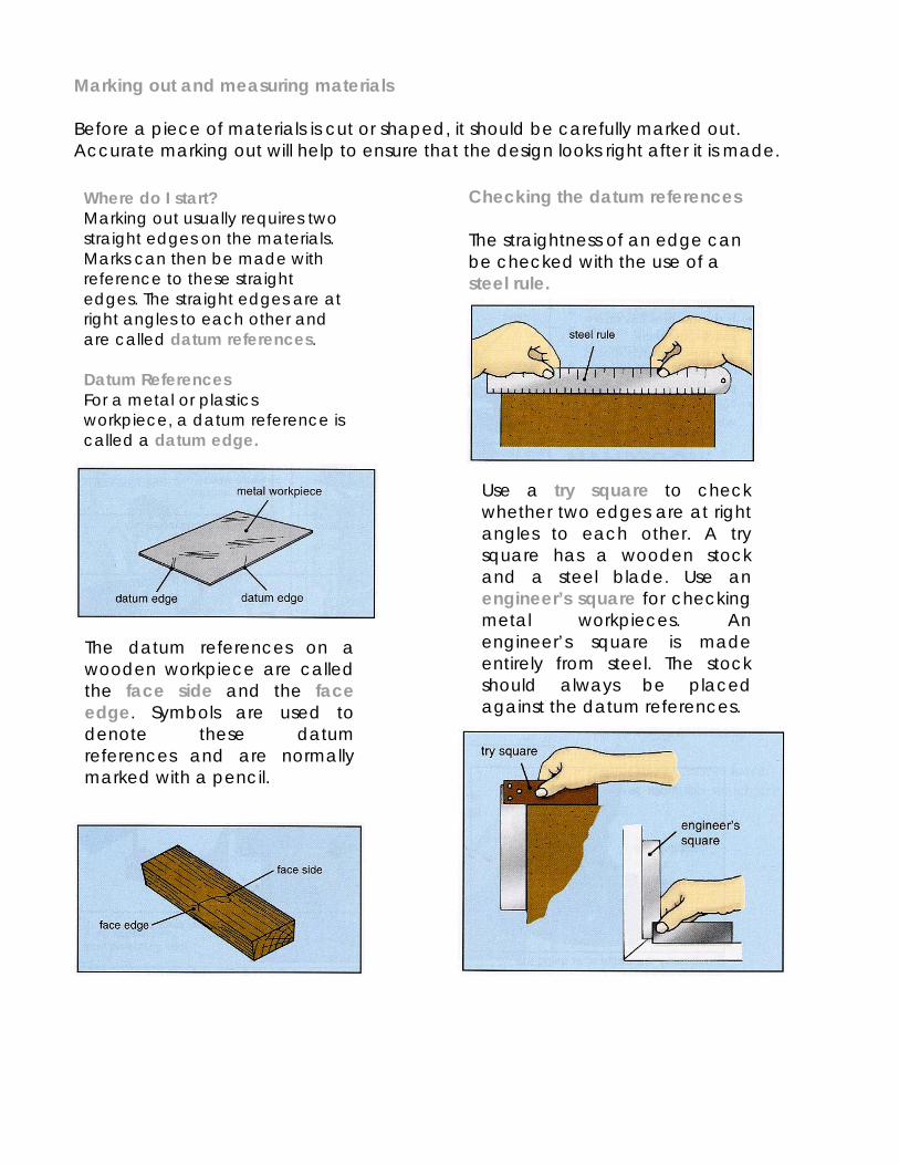
Marking out and measuring materials Before a piece of materials is cut or shaped, it should be carefully marked out. Accurate marking out will help to ensure that the design looks right after it is made.
Where do I start? Marking out usually requires two straight edges on the materials. Marks can then be made with reference to these straight edges. The straight edges are at right angles to each other and are called datum references. Datum References For a metal or plastics workpiece, a datum reference is called a datum edge.
The datum references on a wooden workpiece are called the face side and the face edge. Symbols are used to denote these datum references and are normally marked with a pencil.
Checking the datum references The straightness of an edge can be checked with the use of a steel rule.
Use a try square to check whether two edges are at right angles to each other. A try square has a wooden stock and a steel blade. Use an engineer’s square for checking metal workpieces. An engineer’s square is made entirely from steel. The stock should always be placed against the datum references.
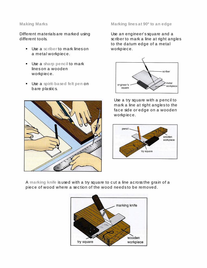
Making Marks Different materials are marked using different tools.
Use a scriber to mark lines on a metal workpiece.
Use a sharp pencil to mark
lines on a wooden workpiece.
Use a spirit-based felt pen on
bare plastics.
Marking lines at 90º to an edge Use an engineer’s square and a scriber to mark a line at right angles to the datum edge of a metal workpiece.
Use a try square with a pencil to mark a line at right angles to the face side or edge on a wooden workpiece.
A marking knife is used with a try square to cut a line across the grain of a piece of wood where a section of the wood needs to be removed.
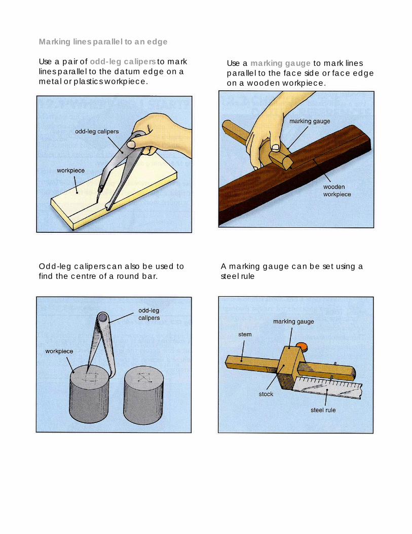
Marking lines parallel to an edge Use a pair of odd-leg calipers to mark lines parallel to the datum edge on a metal or plastics workpiece.
Odd-leg calipers can also be used to find the centre of a round bar.
Use a marking gauge to mark lines parallel to the face side or face edge on a wooden workpiece.
A marking gauge can be set using a steel rule
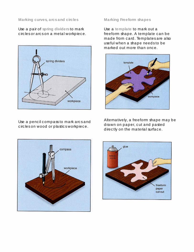
Marking curves, arcs and circles Use a pair of spring dividers to mark circles or arcs on a metal workpiece.
Use a pencil compass to mark arcs and circles on wood or plastics workpiece.
Marking Freeform shapes Use a template to mark out a freeform shape. A template can be made from card. Templates are also useful when a shape needs to be marked out more than once.
Alternatively, a freeform shape may be drawn on paper, cut and pasted directly on the material surface.
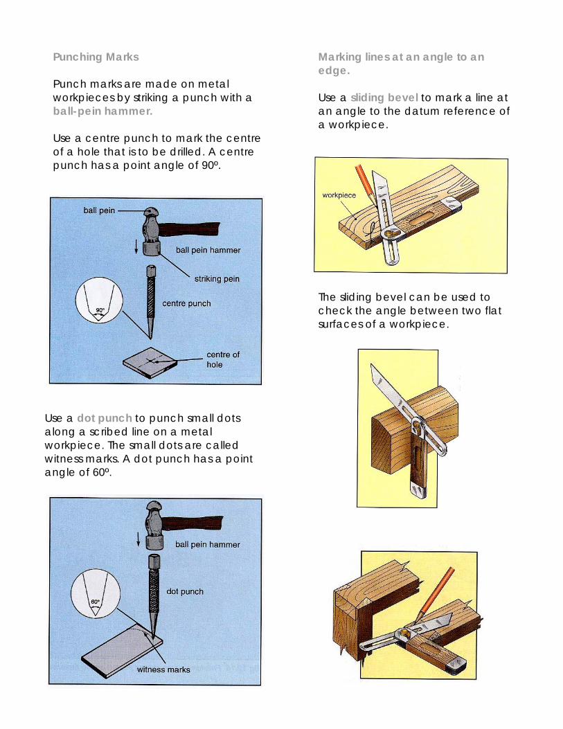
Punching Marks Punch marks are made on metal workpieces by striking a punch with a ball-pein hammer. Use a centre punch to mark the centre of a hole that is to be drilled. A centre punch has a point angle of 90º.
Use a dot punch to punch small dots along a scribed line on a metal workpiece. The small dots are called witness marks. A dot punch has a point angle of 60º.
Marking lines at an angle to an edge. Use a sliding bevel to mark a line at an angle to the datum reference of a workpiece.
The sliding bevel can be used to check the angle between two flat surfaces of a workpiece.
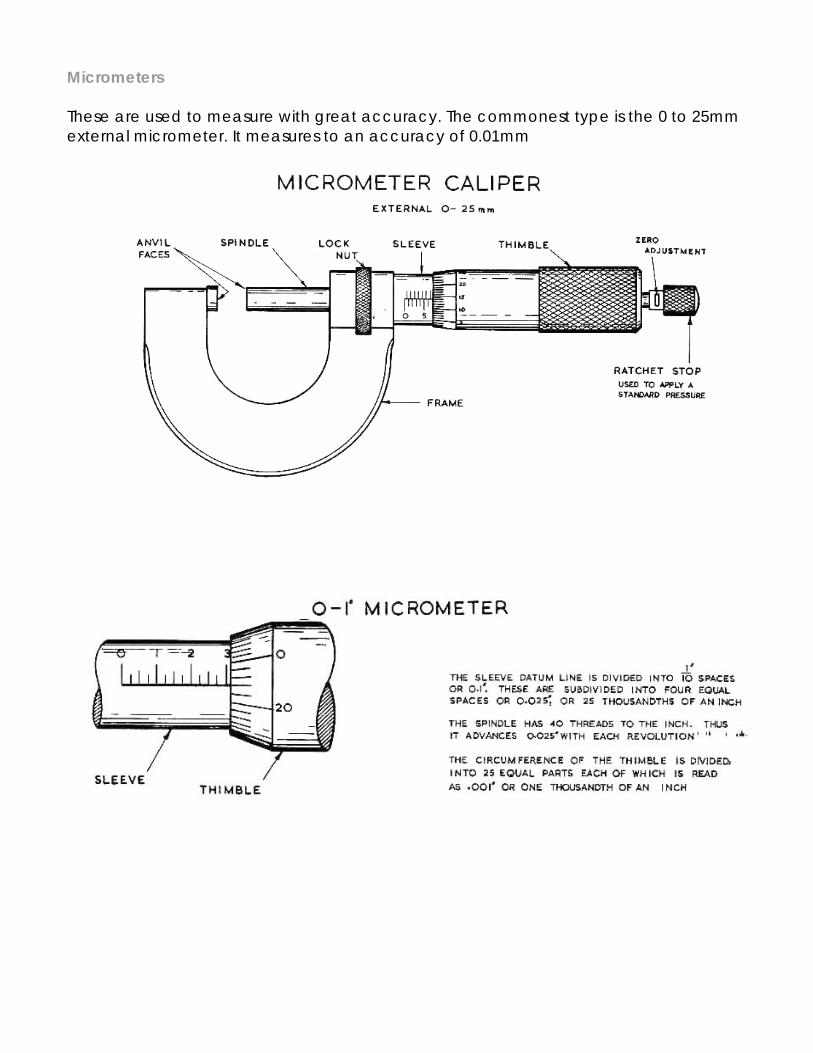
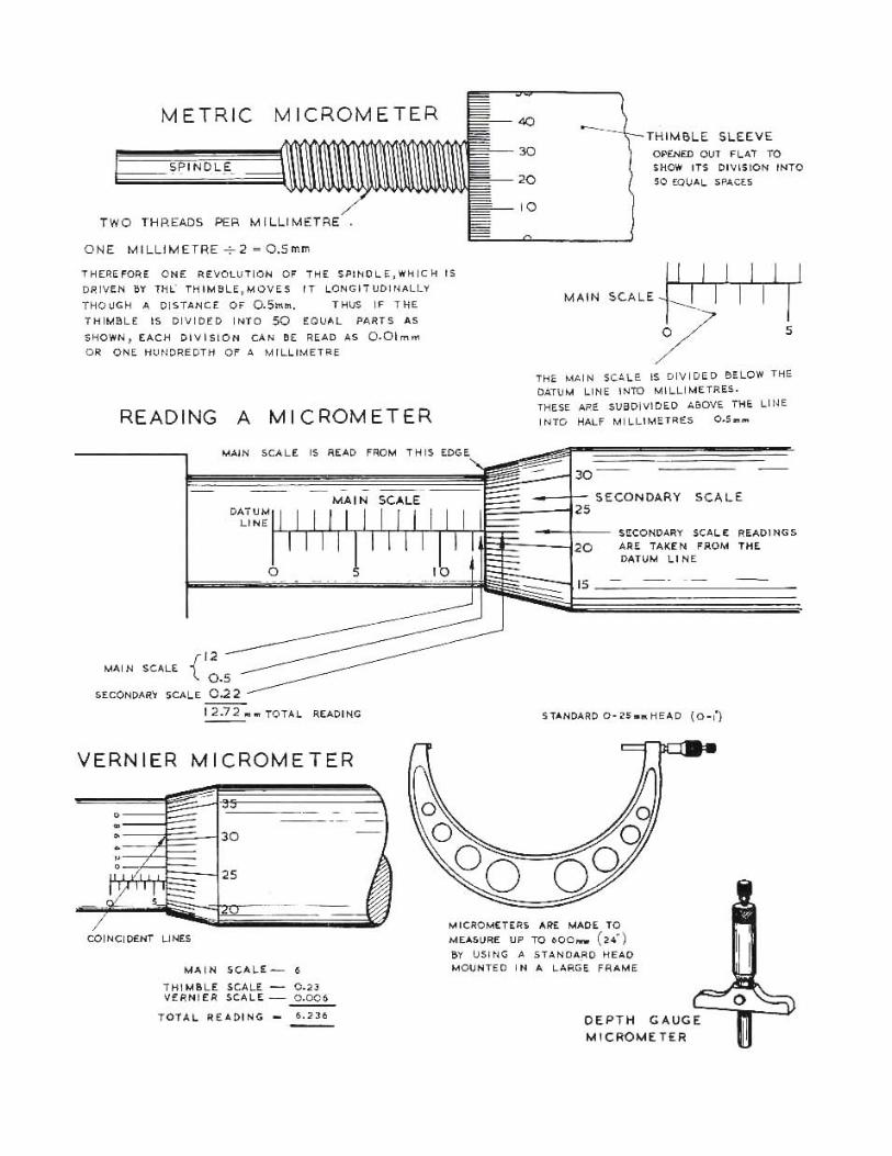
Micrometers These are used to measure with great accuracy. The commonest type is the 0 to 25mm external micrometer. It measures to an accuracy of 0.01mm
Vernier calipers
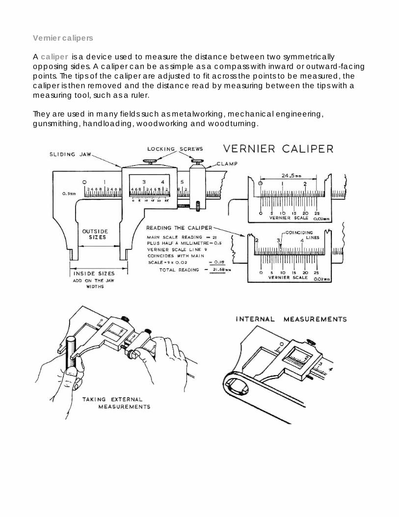
A caliper is a device used to measure the distance between two symmetrically opposing sides. A caliper can be as simple as a compass with inward or outward-facing points. The tips of the caliper are adjusted to fit across the points to be measured, the caliper is then removed and the distance read by measuring between the tips with a measuring tool, such as a ruler.
They are used in many fields such as metalworking, mechanical engineering, gunsmithing, handloading, woodworking and woodturning.
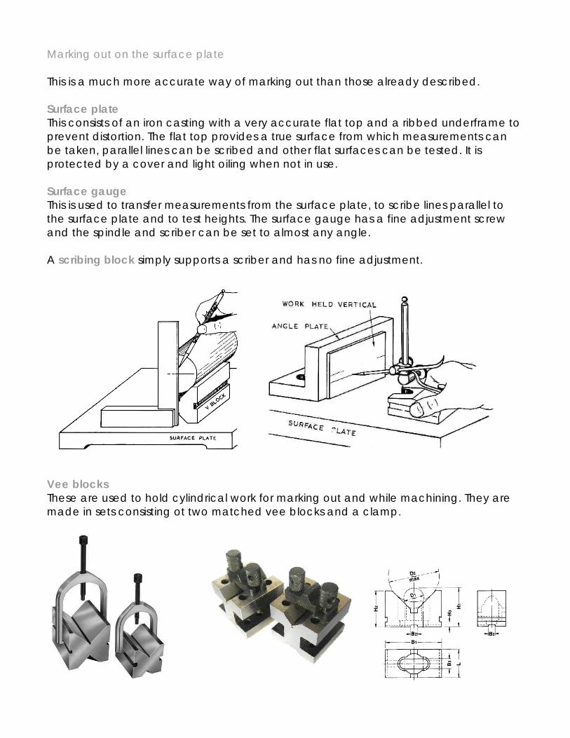
Marking out on the surface plate This is a much more accurate way of marking out than those already described. Surface plate This consists of an iron casting with a very accurate flat top and a ribbed underframe to prevent distortion. The flat top provides a true surface from which measurements can be taken, parallel lines can be scribed and other flat surfaces can be tested. It is protected by a cover and light oiling when not in use. Surface gauge This is used to transfer measurements from the surface plate, to scribe lines parallel to the surface plate and to test heights. The surface gauge has a fine adjustment screw and the spindle and scriber can be set to almost any angle. A scribing block simply supports a scriber and has no fine adjustment.
Vee blocks These are used to hold cylindrical work for marking out and while machining. They are made in sets consisting ot two matched vee blocks and a clamp.
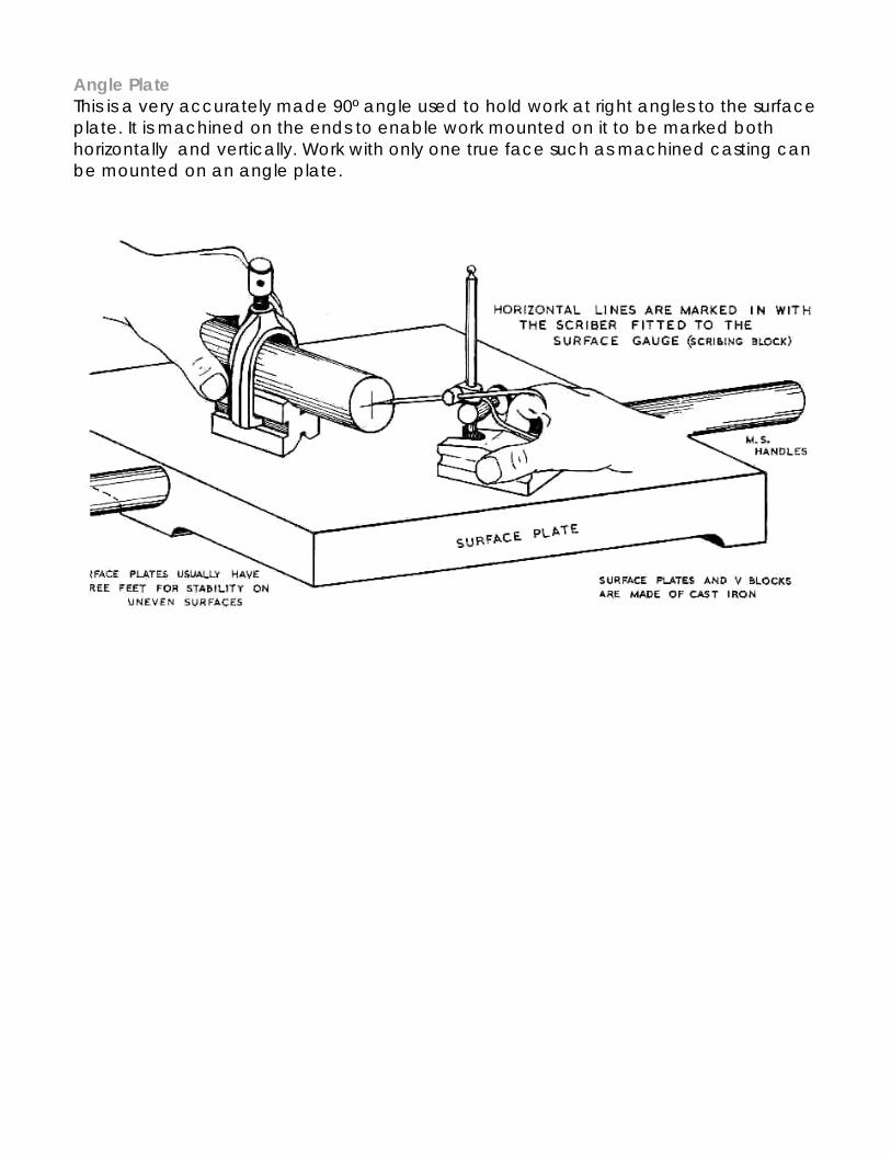
Angle Plate This is a very accurately made 90º angle used to hold work at right angles to the surface plate. It is machined on the ends to enable work mounted on it to be marked both horizontally and vertically. Work with only one true face such as machined casting can be mounted on an angle plate.
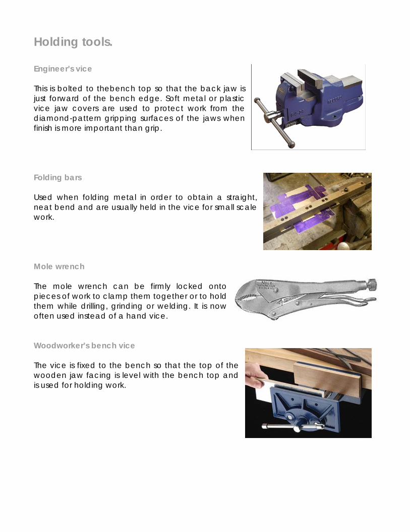
Holding tools. Engineer’s vice This is bolted to thebench top so that the back jaw is just forward of the bench edge. Soft metal or plastic vice jaw covers are used to protect work from the diamond-pattern gripping surfaces of the jaws when finish is more important than grip. Folding bars Used when folding metal in order to obtain a straight, neat bend and are usually held in the vice for small scale work. Mole wrench The mole wrench can be firmly locked onto pieces of work to clamp them together or to hold them while drilling, grinding or welding. It is now often used instead of a hand vice. Woodworker’s bench vice The vice is fixed to the bench so that the top of the wooden jaw facing is level with the bench top and is used for holding work.
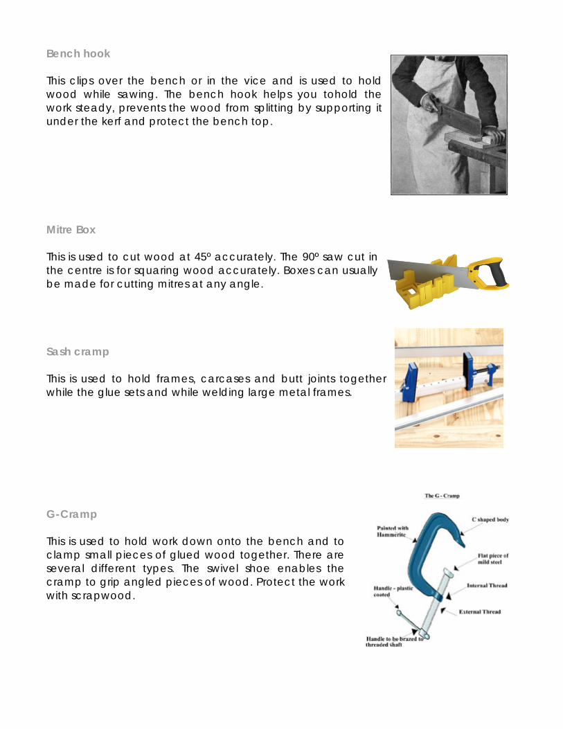
Bench hook This clips over the bench or in the vice and is used to hold wood while sawing. The bench hook helps you tohold the work steady, prevents the wood from splitting by supporting it under the kerf and protect the bench top. Mitre Box This is used to cut wood at 45º accurately. The 90º saw cut in the centre is for squaring wood accurately. Boxes can usually be made for cutting mitres at any angle. Sash cramp This is used to hold frames, carcases and butt joints together while the glue sets and while welding large metal frames. G-Cramp This is used to hold work down onto the bench and to clamp small pieces of glued wood together. There are several different types. The swivel shoe enables the cramp to grip angled pieces of wood. Protect the work with scrapwood.
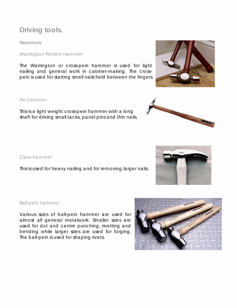
Driving tools. Hammers Warrington Pattern Hammer The Warrington or cross-pein hammer is used for light nailing and general work in cabinet-making. The cross-pein is used for starting small nails held between the fingers. Pin hammer This is a light weight cross-pein hammer with a long shaft for driving small tacks, panel pins and thin nails. Claw-hammer This is used for heavy nailing and for removing larger nails. Ball-pein hammer Various sizes of ball-pein hammer are used for almost all general metalwork. Smaller sizes are used for dot and centre punching, rivetting and bending while larger sizes are used for forging. The ball-pein is used for shaping rivets.
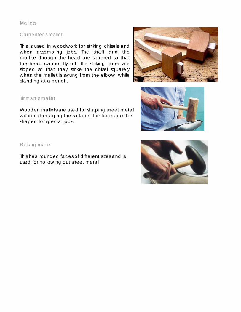
Mallets Carpenter’s mallet This is used in woodwork for striking chisels and when assembling jobs. The shaft and the mortise through the head are tapered so that the head cannot fly off. The striking faces are sloped so that they strike the chisel squarely when the mallet is swung from the elbow, while standing at a bench. Tinman’s mallet Wooden mallets are used for shaping sheet metal without damaging the surface. The faces can be shaped for special jobs. Bossing mallet This has rounded faces of different sizes and is used for hollowing out sheet metal
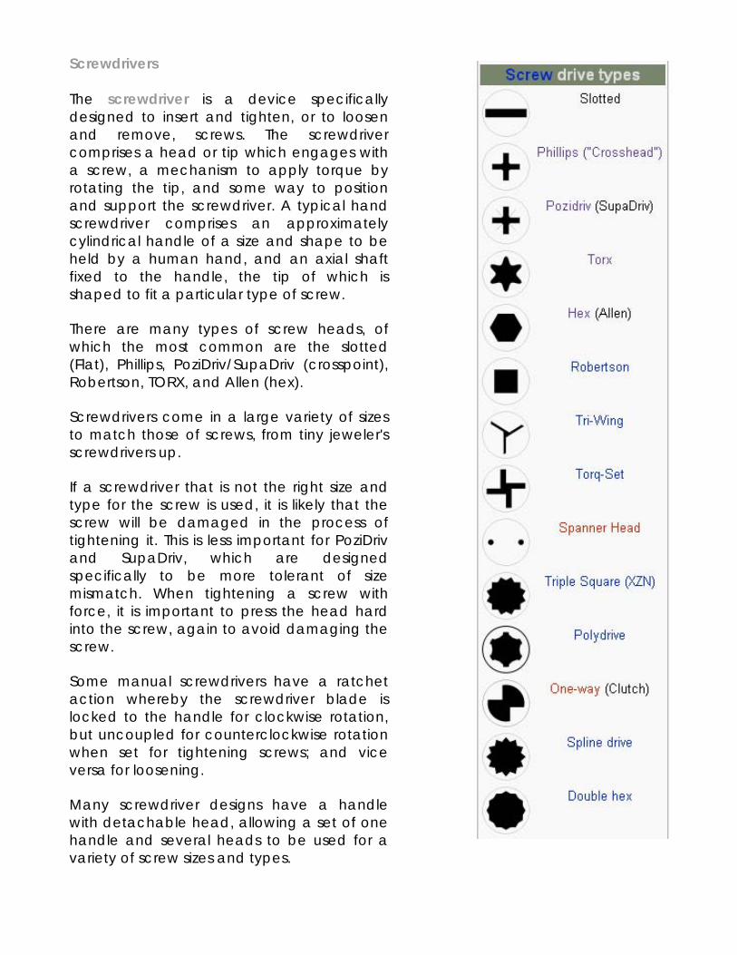
Screwdrivers The screwdriver is a device specifically designed to insert and tighten, or to loosen and remove, screws. The screwdriver comprises a head or tip which engages with a screw, a mechanism to apply torque by rotating the tip, and some way to position and support the screwdriver. A typical hand screwdriver comprises an approximately cylindrical handle of a size and shape to be held by a human hand, and an axial shaft fixed to the handle, the tip of which is shaped to fit a particular type of screw.
There are many types of screw heads, of which the most common are the slotted (Flat), Phillips, PoziDriv/SupaDriv (crosspoint), Robertson, TORX, and Allen (hex).
Screwdrivers come in a large variety of sizes to match those of screws, from tiny jeweler's screwdrivers up.
If a screwdriver that is not the right size and type for the screw is used, it is likely that the screw will be damaged in the process of tightening it. This is less important for PoziDriv and SupaDriv, which are designed specifically to be more tolerant of size mismatch. When tightening a screw with force, it is important to press the head hard into the screw, again to avoid damaging the screw.
Some manual screwdrivers have a ratchet action whereby the screwdriver blade is locked to the handle for clockwise rotation, but uncoupled for counterclockwise rotation when set for tightening screws; and vice versa for loosening.
Many screwdriver designs have a handle with detachable head, allowing a set of one handle and several heads to be used for a variety of screw sizes and types.
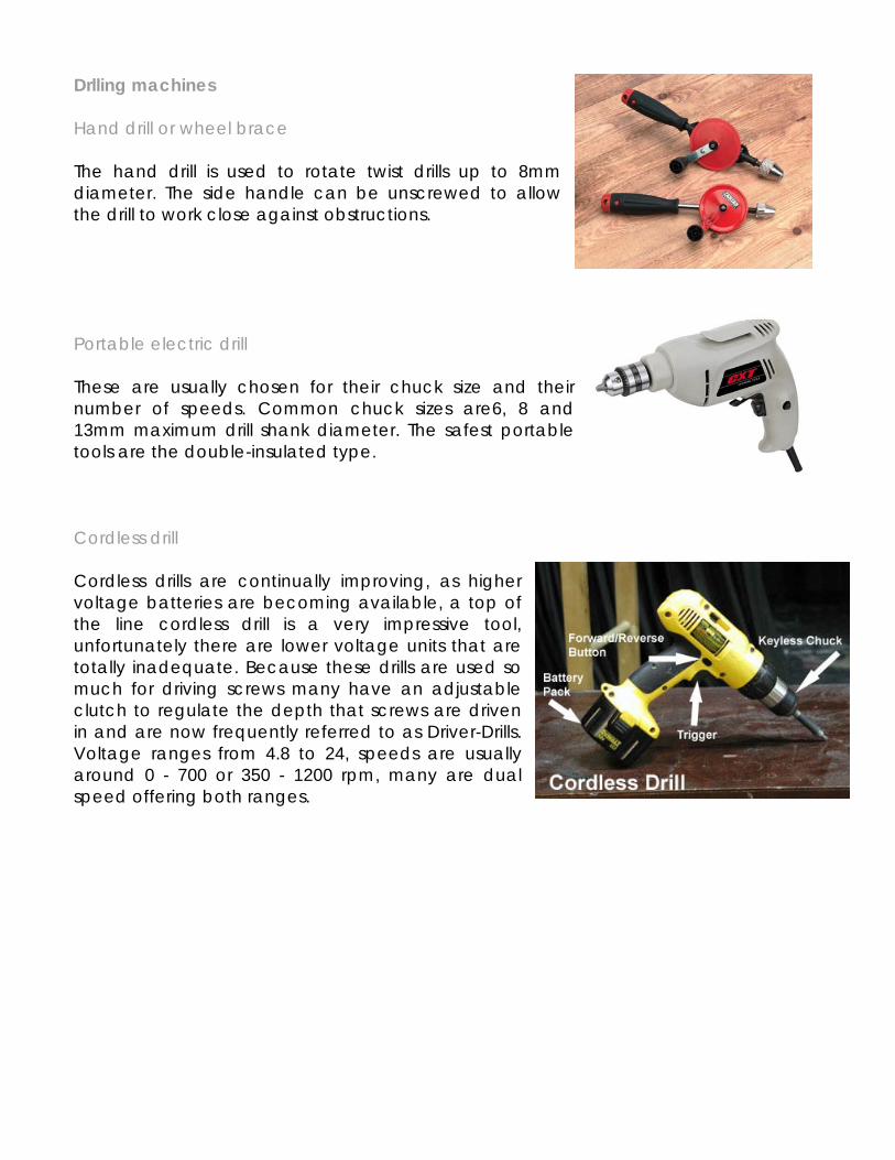
Drlling machines Hand drill or wheel brace The hand drill is used to rotate twist drills up to 8mm diameter. The side handle can be unscrewed to allow the drill to work close against obstructions. Portable electric drill These are usually chosen for their chuck size and their number of speeds. Common chuck sizes are6, 8 and 13mm maximum drill shank diameter. The safest portable tools are the double-insulated type. Cordless drill Cordless drills are continually improving, as higher voltage batteries are becoming available, a top of the line cordless drill is a very impressive tool, unfortunately there are lower voltage units that are totally inadequate. Because these drills are used so much for driving screws many have an adjustable clutch to regulate the depth that screws are driven in and are now frequently referred to as Driver-Drills. Voltage ranges from 4.8 to 24, speeds are usually around 0 - 700 or 350 - 1200 rpm, many are dual speed offering both ranges.
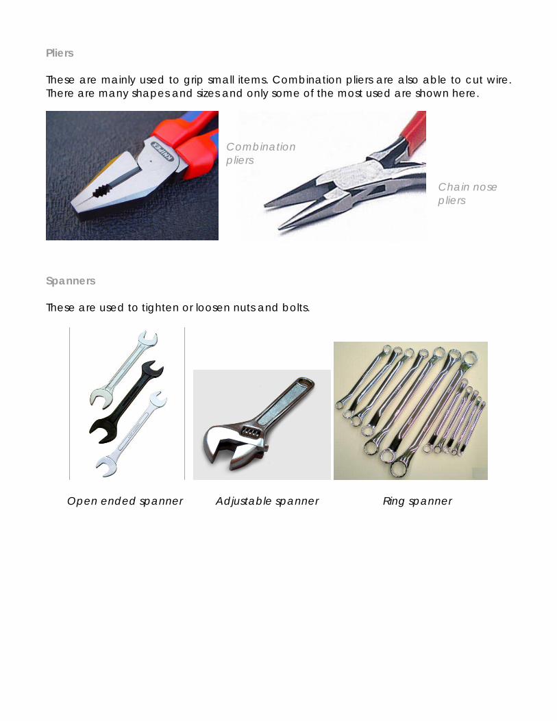
Pliers These are mainly used to grip small items. Combination pliers are also able to cut wire. There are many shapes and sizes and only some of the most used are shown here.
Combination pliers Chain nose pliers
Spanners These are used to tighten or loosen nuts and bolts.
Open ended spanner Adjustable spanner Ring spanner
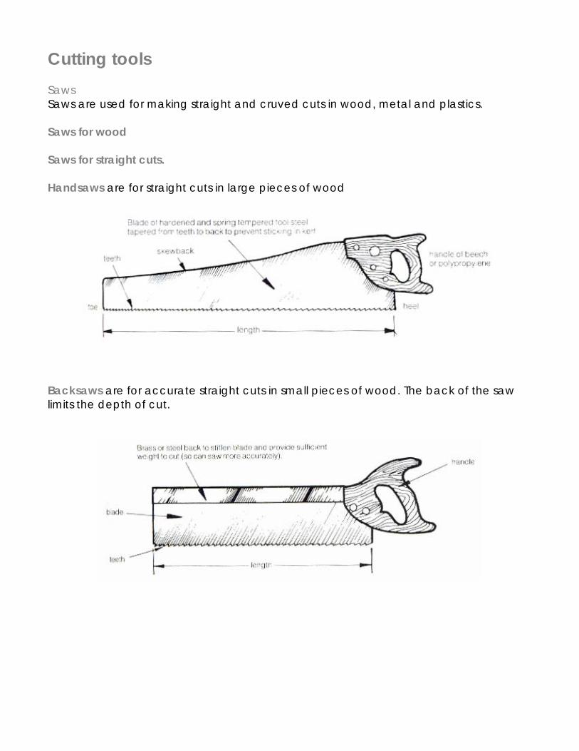
Cutting tools Saws Saws are used for making straight and cruved cuts in wood, metal and plastics. Saws for wood Saws for straight cuts. Handsaws are for straight cuts in large pieces of wood
Backsaws are for accurate straight cuts in small pieces of wood. The back of the saw limits the depth of cut.
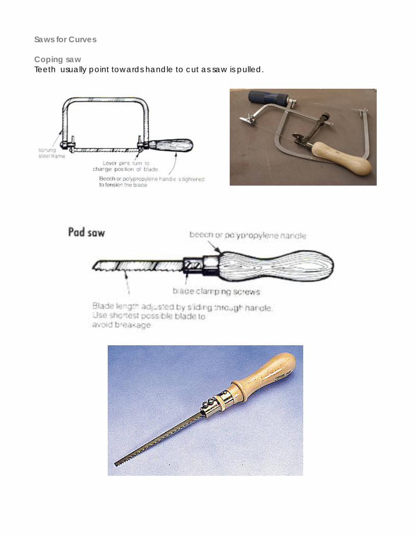
Saws for Curves Coping saw Teeth usually point towards handle to cut as saw is pulled.
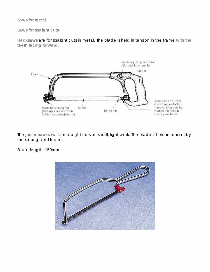
Saws for metal Saws for straight cuts Hacksaws are for straight cuts in metal. The blade is held in tension in the frame with the teeth facing forward.
The junior hacksaw is for straight cuts on small, light work. The blade is held in tension by the sprung steel frame. Blade length: 150mm
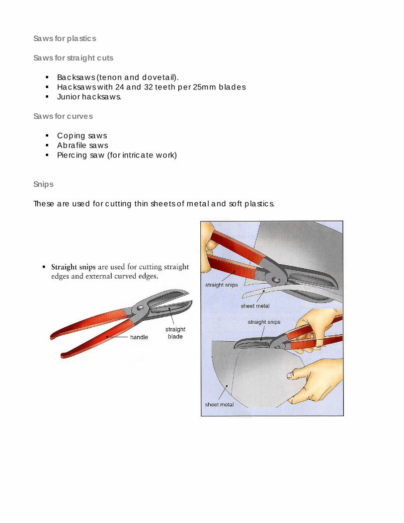
Saws for plastics Saws for straight cuts
Backsaws (tenon and dovetail). Hacksaws with 24 and 32 teeth per 25mm blades Junior hacksaws.
Saws for curves
Coping saws Abrafile saws Piercing saw (for intricate work)
Snips These are used for cutting thin sheets of metal and soft plastics.
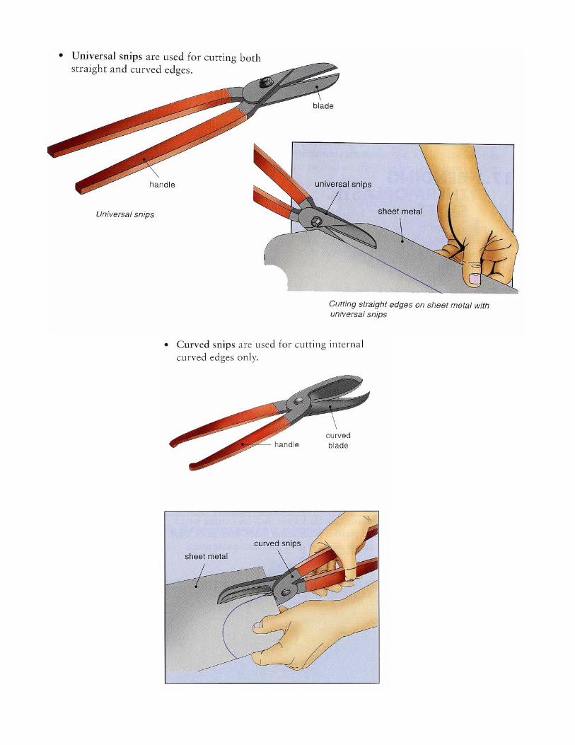
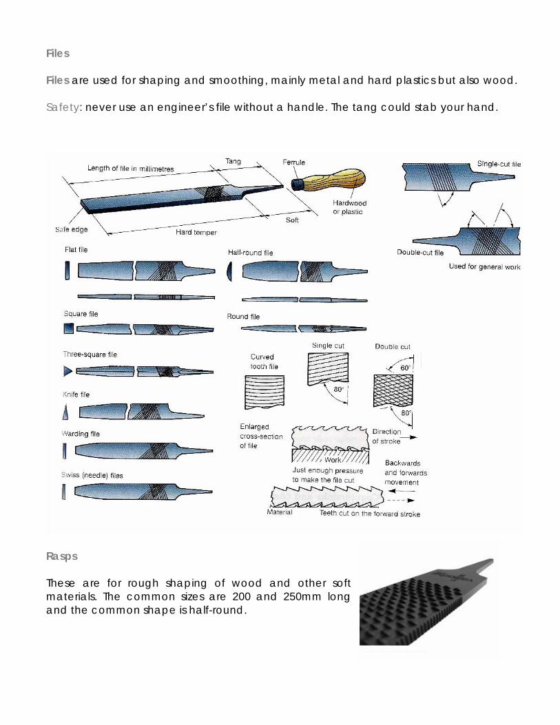
Files Files are used for shaping and smoothing, mainly metal and hard plastics but also wood. Safety: never use an engineer’s file without a handle. The tang could stab your hand.
Rasps These are for rough shaping of wood and other soft materials. The common sizes are 200 and 250mm long and the common shape is half-round.
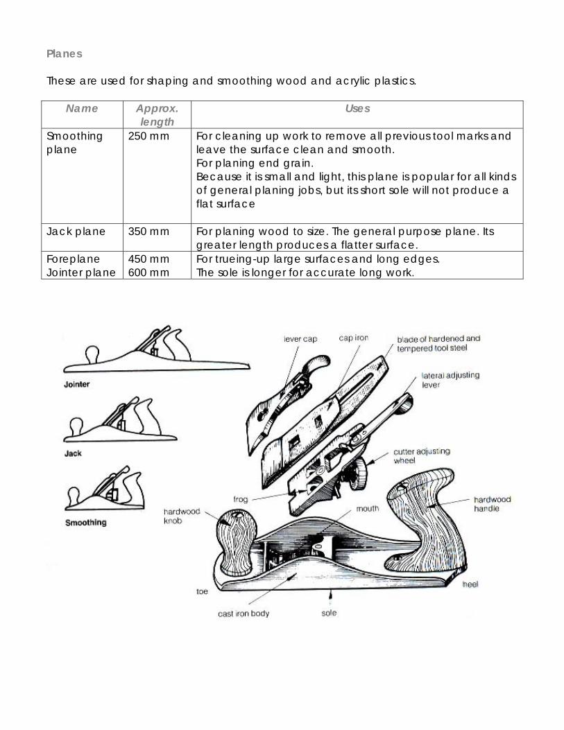
Planes These are used for shaping and smoothing wood and acrylic plastics.
Name Approx. length
Uses
Smoothing plane
250 mm For cleaning up work to remove all previous tool marks and leave the surface clean and smooth. For planing end grain. Because it is small and light, this plane is popular for all kinds of general planing jobs, but its short sole will not produce a flat surface
Jack plane 350 mm For planing wood to size. The general purpose plane. Its greater length produces a flatter surface.
Foreplane Jointer plane
450 mm 600 mm
For trueing-up large surfaces and long edges. The sole is longer for accurate long work.
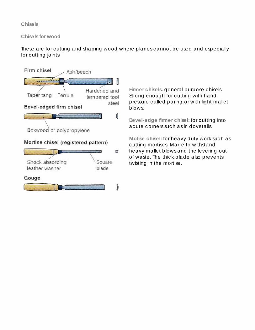
Chisels Chisels for wood These are for cutting and shaping wood where planes cannot be used and especially for cutting joints.
Firmer chisels: general purpose chisels. Strong enough for cutting with hand pressure called paring or with light mallet blows. Bevel-edge firmer chisel: for cutting into acute corners such as in dovetails. Motise chisel: for heavy duty work such as cutting mortises. Made to withstand heavy mallet blows and the levering-out of waste. The thick blade also prevents twisting in the mortise.
IGCSE Resistant Material
Topic: Ways of working materials (processes)
Student Name: Tutor Group:
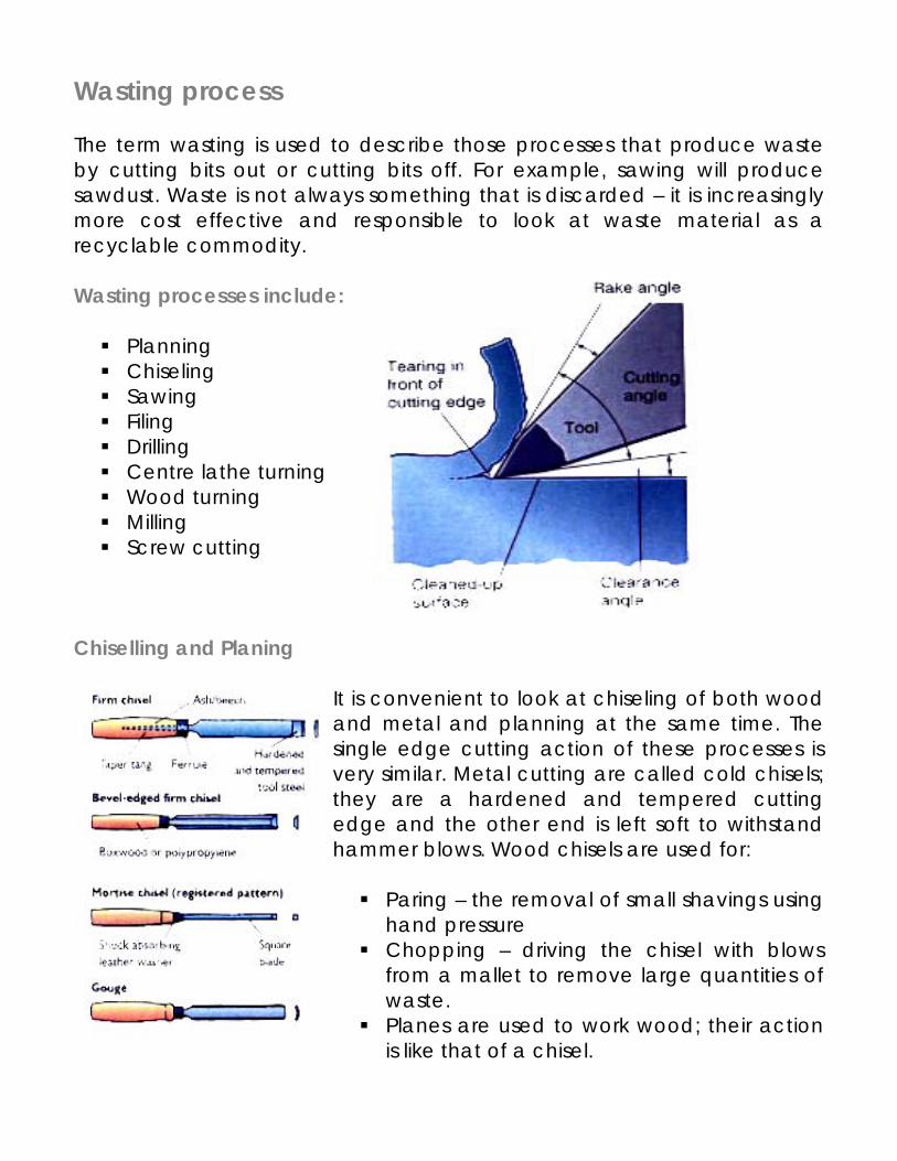
Wasting process The term wasting is used to describe those processes that produce waste by cutting bits out or cutting bits off. For example, sawing will produce sawdust. Waste is not always something that is discarded – it is increasingly more cost effective and responsible to look at waste material as a recyclable commodity. Wasting processes include:
Planning Chiseling Sawing Filing Drilling Centre lathe turning Wood turning Milling Screw cutting
Chiselling and Planing
It is convenient to look at chiseling of both wood and metal and planning at the same time. The single edge cutting action of these processes is very similar. Metal cutting are called cold chisels; they are a hardened and tempered cutting edge and the other end is left soft to withstand hammer blows. Wood chisels are used for:
Paring – the removal of small shavings using hand pressure
Chopping – driving the chisel with blows from a mallet to remove large quantities of waste.
Planes are used to work wood; their action is like that of a chisel.
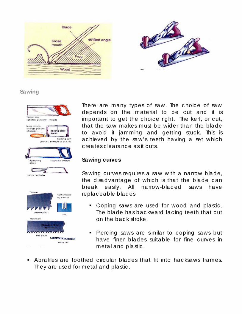
Sawing
There are many types of saw. The choice of saw depends on the material to be cut and it is important to get the choice right. The kerf, or cut, that the saw makes must be wider than the blade to avoid it jamming and getting stuck. This is achieved by the saw’s teeth having a set which creates clearance as it cuts. Sawing curves Sawing curves requires a saw with a narrow blade, the disadvantage of which is that the blade can break easily. All narrow-bladed saws have replaceable blades
Coping saws are used for wood and plastic. The blade has backward facing teeth that cut on the back stroke.
Piercing saws are similar to coping saws but
have finer blades suitable for fine curves in metal and plastic.
Abrafiles are toothed circular blades that fit into hacksaws frames.
They are used for metal and plastic.
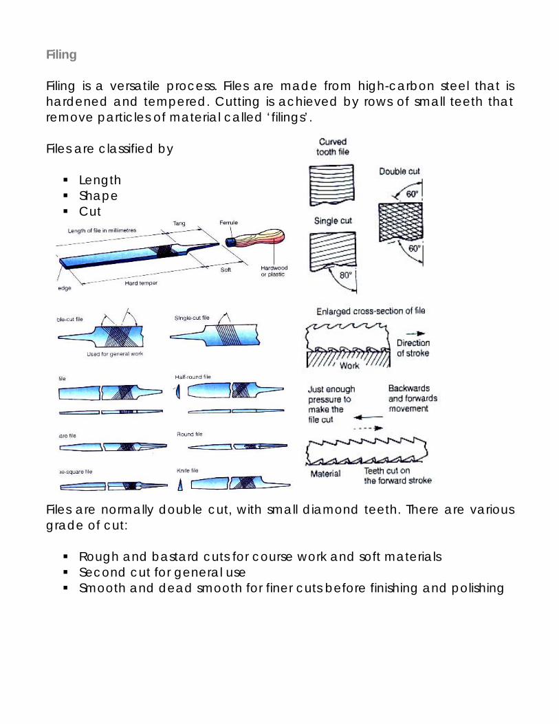
Filing Filing is a versatile process. Files are made from high-carbon steel that is hardened and tempered. Cutting is achieved by rows of small teeth that remove particles of material called ‘filings’. Files are classified by
Length Shape Cut
Files are normally double cut, with small diamond teeth. There are various grade of cut:
Rough and bastard cuts for course work and soft materials Second cut for general use Smooth and dead smooth for finer cuts before finishing and polishing
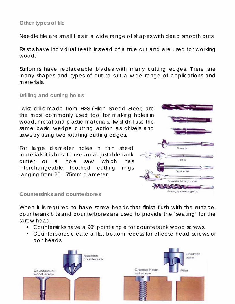
Other types of file Needle file are small files in a wide range of shapes with dead smooth cuts. Rasps have individual teeth instead of a true cut and are used for working wood. Surforms have replaceable blades with many cutting edges. There are many shapes and types of cut to suit a wide range of applications and materials. Drilling and cutting holes Twist drills made from HSS (High Speed Steel) are the most commonly used tool for making holes in wood, metal and plastic materials. Twist drill use the same basic wedge cutting action as chisels and saws by using two rotating cutting edges. For large diameter holes in thin sheet materials it is best to use an adjustable tank cutter or a hole saw which has interchangeable toothed cutting rings ranging from 20 – 75mm diameter. Countersinks and counterbores When it is required to have screw heads that finish flush with the surface, countersink bits and counterbores are used to provide the ‘seating’ for the screw head.
Countersinks have a 90º point angle for countersunk wood screws. Counterbores create a flat bottom recess for cheese head screws or
bolt heads.
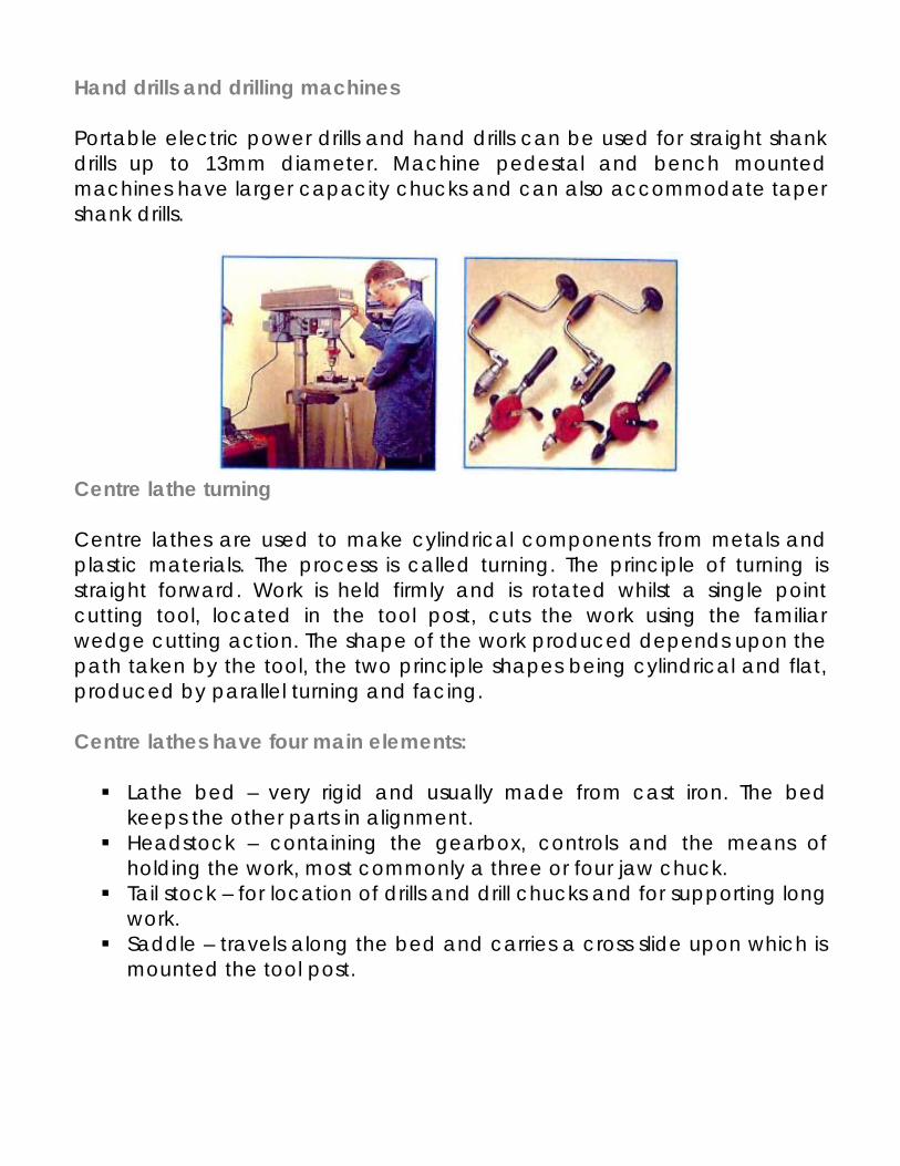
Hand drills and drilling machines Portable electric power drills and hand drills can be used for straight shank drills up to 13mm diameter. Machine pedestal and bench mounted machines have larger capacity chucks and can also accommodate taper shank drills.
Centre lathe turning Centre lathes are used to make cylindrical components from metals and plastic materials. The process is called turning. The principle of turning is straight forward. Work is held firmly and is rotated whilst a single point cutting tool, located in the tool post, cuts the work using the familiar wedge cutting action. The shape of the work produced depends upon the path taken by the tool, the two principle shapes being cylindrical and flat, produced by parallel turning and facing. Centre lathes have four main elements:
Lathe bed – very rigid and usually made from cast iron. The bed keeps the other parts in alignment.
Headstock – containing the gearbox, controls and the means of holding the work, most commonly a three or four jaw chuck.
Tail stock – for location of drills and drill chucks and for supporting long work.
Saddle – travels along the bed and carries a cross slide upon which is mounted the tool post.
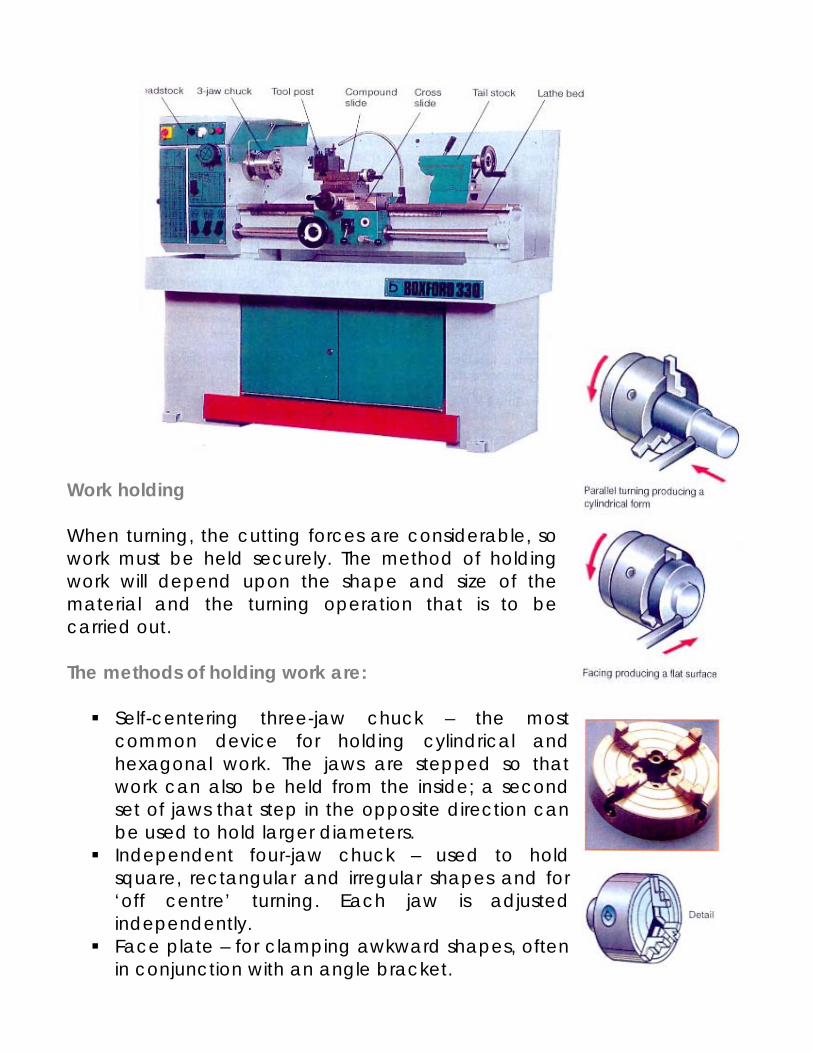
Work holding When turning, the cutting forces are considerable, so work must be held securely. The method of holding work will depend upon the shape and size of the material and the turning operation that is to be carried out. The methods of holding work are:
Self-centering three-jaw chuck – the most common device for holding cylindrical and hexagonal work. The jaws are stepped so that work can also be held from the inside; a second set of jaws that step in the opposite direction can be used to hold larger diameters.
Independent four-jaw chuck – used to hold square, rectangular and irregular shapes and for ‘off centre’ turning. Each jaw is adjusted independently.
Face plate – for clamping awkward shapes, often in conjunction with an angle bracket.
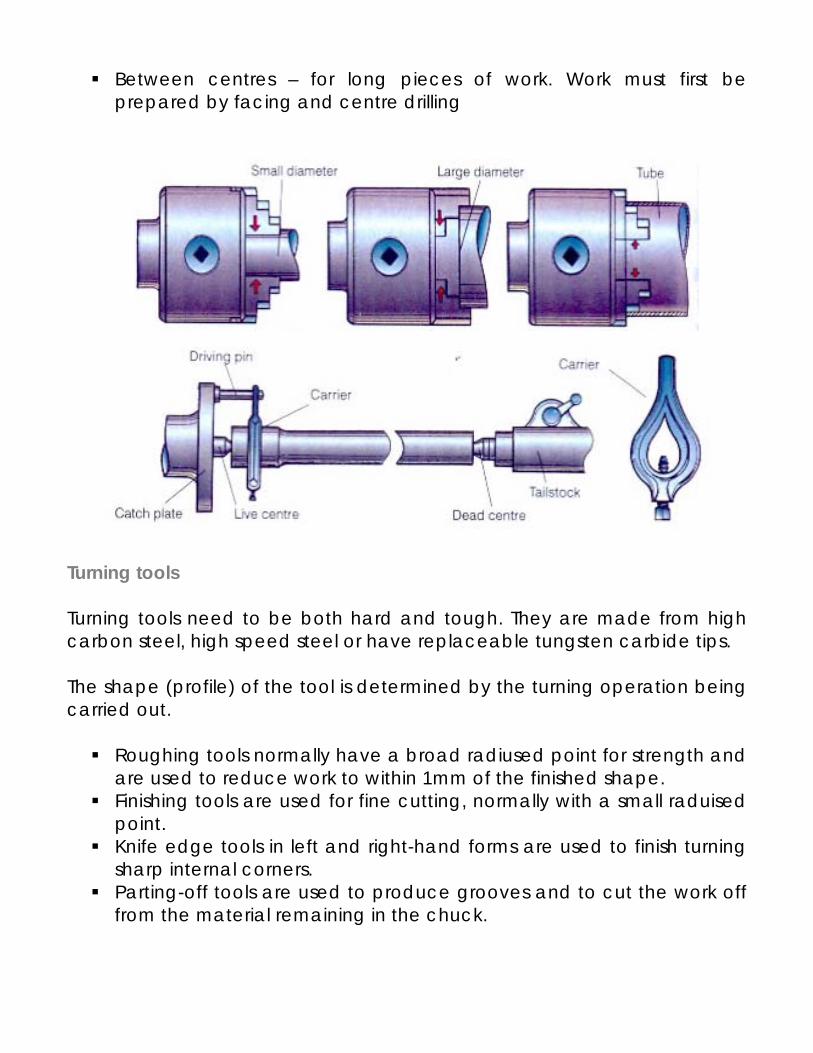
Between centres – for long pieces of work. Work must first be prepared by facing and centre drilling
Turning tools Turning tools need to be both hard and tough. They are made from high carbon steel, high speed steel or have replaceable tungsten carbide tips. The shape (profile) of the tool is determined by the turning operation being carried out.
Roughing tools normally have a broad radiused point for strength and are used to reduce work to within 1mm of the finished shape.
Finishing tools are used for fine cutting, normally with a small raduised point.
Knife edge tools in left and right-hand forms are used to finish turning sharp internal corners.
Parting-off tools are used to produce grooves and to cut the work off from the material remaining in the chuck.
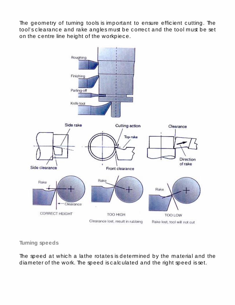
The geometry of turning tools is important to ensure efficient cutting. The tool’s clearance and rake angles must be correct and the tool must be set on the centre line height of the workpiece.
Turning speeds The speed at which a lathe rotates is determined by the material and the diameter of the work. The speed is calculated and the right speed is set.
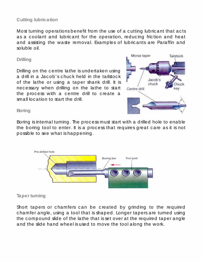
Cutting lubrication Most turning operations benefit from the use of a cutting lubricant that acts as a coolant and lubricant for the operation, reducing friction and heat and assisting the waste removal. Examples of lubricants are Paraffin and soluble oil. Drilling Drilling on the centre lathe is undertaken using a drill in a Jacob’s chuck held in the tailstock of the lathe or using a taper shank drill. It is necessary when drilling on the lathe to start the process with a centre drill to create a small location to start the drill. Boring Boring is internal turning. The process must start with a drilled hole to enable the boring tool to enter. It is a process that requires great care as it is not possible to see what is happening. Taper turning Short tapers or chamfers can be created by grinding to the required chamfer angle, using a tool that is shaped. Longer tapers are turned using the compound slide of the lathe that is set over at the required taper angle and the slide hand wheel is used to move the tool along the work.
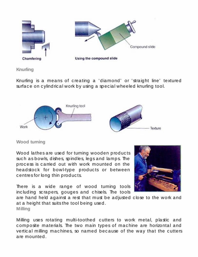
Knurling Knurling is a means of creating a ‘diamond’ or ‘straight line’ textured surface on cylindrical work by using a special wheeled knurling tool.
Wood turning Wood lathes are used for turning wooden products such as bowls, dishes, spindles, legs and lamps. The process is carried out with work mounted on the headstock for bowl-type products or between centres for long thin products. There is a wide range of wood turning tools including scrapers, gouges and chisels. The tools are hand held against a rest that must be adjusted close to the work and at a height that suits the tool being used. Milling Milling uses rotating multi-toothed cutters to work metal, plastic and composite materials. The two main types of machine are horizontal and vertical milling machines, so named because of the way that the cutters are mounted.
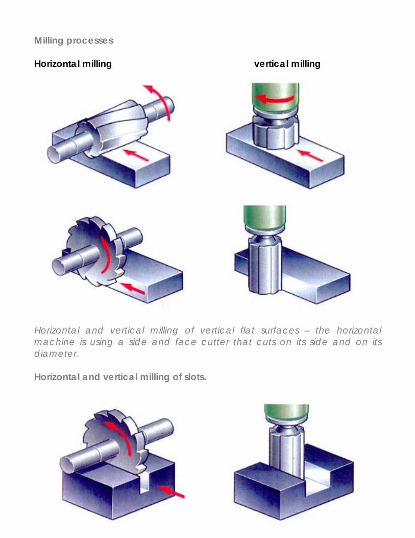
Milling processes Horizontal milling vertical milling
Horizontal and vertical milling of vertical flat surfaces – the horizontal machine is using a side and face cutter that cuts on its side and on its diameter. Horizontal and vertical milling of slots.
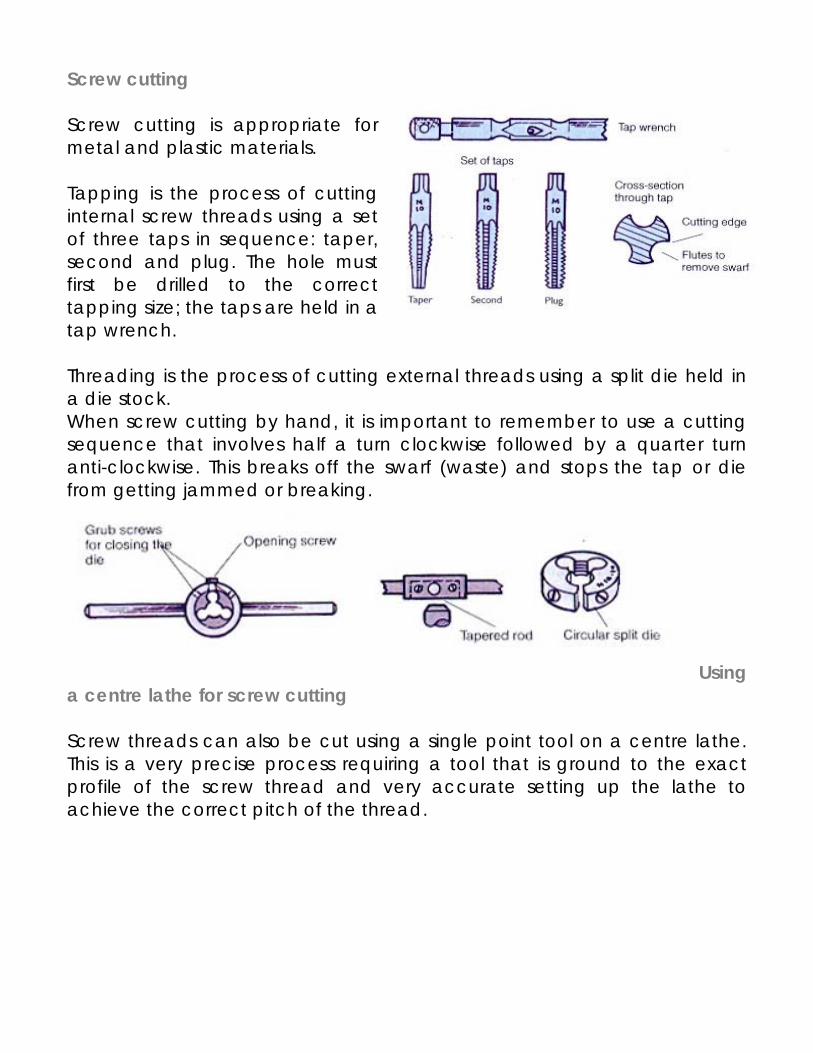
Screw cutting Screw cutting is appropriate for metal and plastic materials. Tapping is the process of cutting internal screw threads using a set of three taps in sequence: taper, second and plug. The hole must first be drilled to the correct tapping size; the taps are held in a tap wrench. Threading is the process of cutting external threads using a split die held in a die stock. When screw cutting by hand, it is important to remember to use a cutting sequence that involves half a turn clockwise followed by a quarter turn anti-clockwise. This breaks off the swarf (waste) and stops the tap or die from getting jammed or breaking.
Using a centre lathe for screw cutting Screw threads can also be cut using a single point tool on a centre lathe. This is a very precise process requiring a tool that is ground to the exact profile of the screw thread and very accurate setting up the lathe to achieve the correct pitch of the thread.
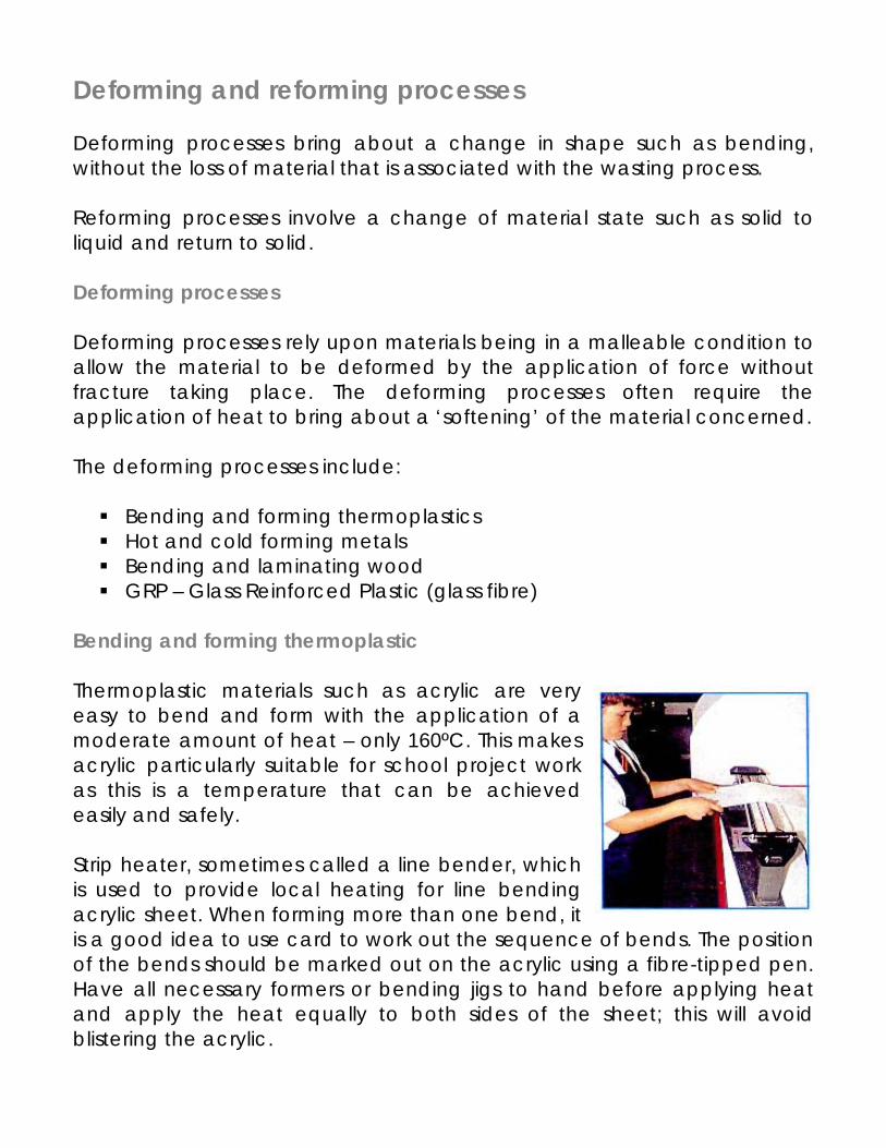
Deforming and reforming processes Deforming processes bring about a change in shape such as bending, without the loss of material that is associated with the wasting process. Reforming processes involve a change of material state such as solid to liquid and return to solid. Deforming processes Deforming processes rely upon materials being in a malleable condition to allow the material to be deformed by the application of force without fracture taking place. The deforming processes often require the application of heat to bring about a ‘softening’ of the material concerned. The deforming processes include:
Bending and forming thermoplastics Hot and cold forming metals Bending and laminating wood GRP – Glass Reinforced Plastic (glass fibre)
Bending and forming thermoplastic Thermoplastic materials such as acrylic are very easy to bend and form with the application of a moderate amount of heat – only 160ºC. This makes acrylic particularly suitable for school project work as this is a temperature that can be achieved easily and safely. Strip heater, sometimes called a line bender, which is used to provide local heating for line bending acrylic sheet. When forming more than one bend, it is a good idea to use card to work out the sequence of bends. The position of the bends should be marked out on the acrylic using a fibre-tipped pen. Have all necessary formers or bending jigs to hand before applying heat and apply the heat equally to both sides of the sheet; this will avoid blistering the acrylic.
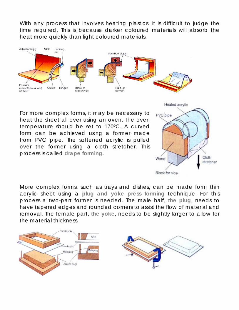
With any process that involves heating plastics, it is difficult to judge the time required. This is because darker coloured materials will absorb the heat more quickly than light coloured materials.
For more complex forms, it may be necessary to heat the sheet all over using an oven. The oven temperature should be set to 170ºC. A curved form can be achieved using a former made from PVC pipe. The softened acrylic is pulled over the former using a cloth stretcher. This process is called drape forming. More complex forms, such as trays and dishes, can be made form thin acrylic sheet using a plug and yoke press forming technique. For this process a two-part former is needed. The male half, the plug, needs to have tapered edges and rounded corners to assist the flow of material and removal. The female part, the yoke, needs to be slightly larger to allow for the material thickness.
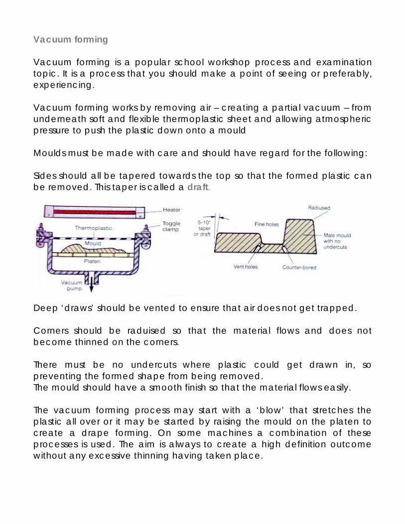
Vacuum forming Vacuum forming is a popular school workshop process and examination topic. It is a process that you should make a point of seeing or preferably, experiencing. Vacuum forming works by removing air – creating a partial vacuum – from underneath soft and flexible thermoplastic sheet and allowing atmospheric pressure to push the plastic down onto a mould Moulds must be made with care and should have regard for the following: Sides should all be tapered towards the top so that the formed plastic can be removed. This taper is called a draft.
Deep ‘draws’ should be vented to ensure that air does not get trapped. Corners should be raduised so that the material flows and does not become thinned on the corners. There must be no undercuts where plastic could get drawn in, so preventing the formed shape from being removed. The mould should have a smooth finish so that the material flows easily. The vacuum forming process may start with a ‘blow’ that stretches the plastic all over or it may be started by raising the mould on the platen to create a drape forming. On some machines a combination of these processes is used. The aim is always to create a high definition outcome without any excessive thinning having taken place.
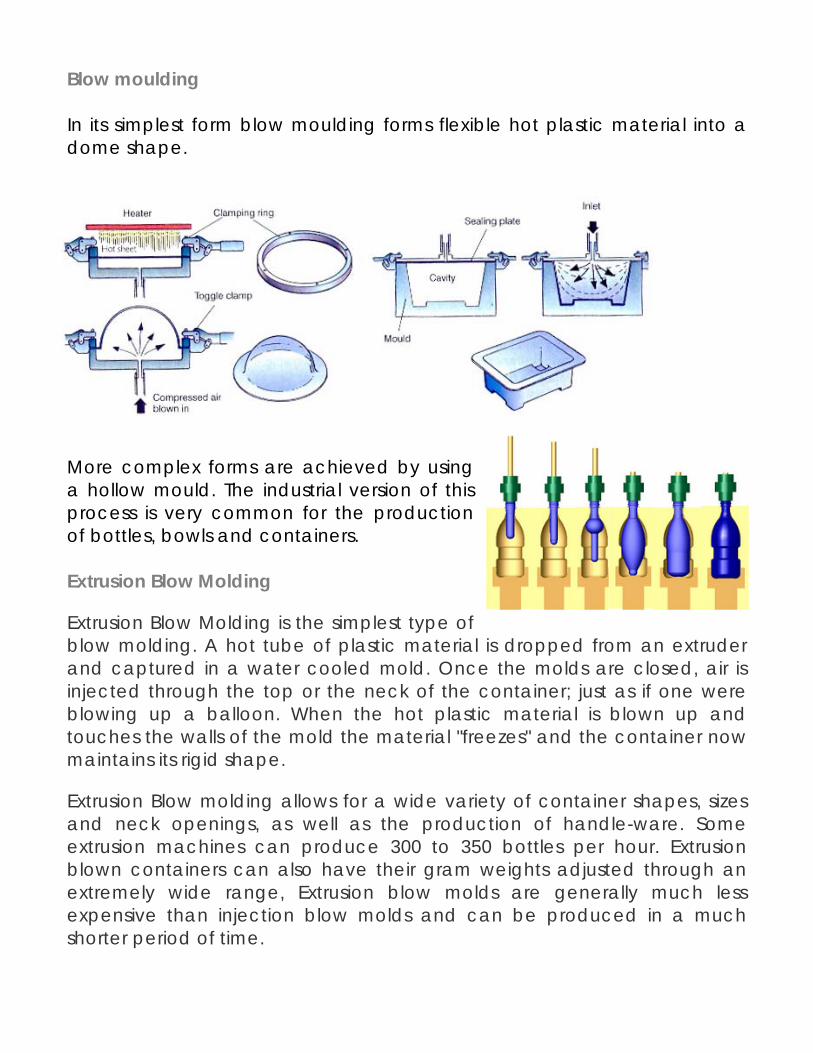
Blow moulding In its simplest form blow moulding forms flexible hot plastic material into a dome shape.
More complex forms are achieved by using a hollow mould. The industrial version of this process is very common for the production of bottles, bowls and containers. Extrusion Blow Molding
Extrusion Blow Molding is the simplest type of blow molding. A hot tube of plastic material is dropped from an extruder and captured in a water cooled mold. Once the molds are closed, air is injected through the top or the neck of the container; just as if one were blowing up a balloon. When the hot plastic material is blown up and touches the walls of the mold the material "freezes" and the container now maintains its rigid shape.
Extrusion Blow molding allows for a wide variety of container shapes, sizes and neck openings, as well as the production of handle-ware. Some extrusion machines can produce 300 to 350 bottles per hour. Extrusion blown containers can also have their gram weights adjusted through an extremely wide range, Extrusion blow molds are generally much less expensive than injection blow molds and can be produced in a much shorter period of time.
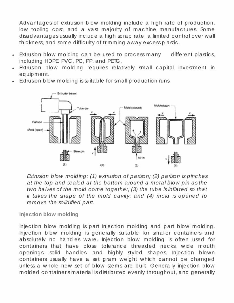
Advantages of extrusion blow molding include a high rate of production, low tooling cost, and a vast majority of machine manufactures. Some disadvantages usually include a high scrap rate, a limited control over wall thickness, and some difficulty of trimming away excess plastic.
• Extrusion blow molding can be used to process many different plastics, including HDPE, PVC, PC, PP, and PETG.
• Extrusion blow molding requires relatively small capital investment in equipment.
• Extrusion blow molding is suitable for small production runs.
Extrusion blow molding: (1) extrusion of parison; (2) parison is pinches at the top and sealed at the bottom around a metal blow pin as the two halves of the mold come together; (3) the tube is inflated so that it takes the shape of the mold cavity; and (4) mold is opened to remove the solidified part.
Injection blow molding
Injection blow molding is part injection molding and part blow molding. Injection blow molding is generally suitable for smaller containers and absolutely no handles ware. Injection blow molding is often used for containers that have close tolerance threaded necks, wide mouth openings; solid handles, and highly styled shapes. Injection blown containers usually have a set gram weight which cannot be changed unless a whole new set of blow stems are built. Generally injection blow molded container's material is distributed evenly throughout, and generally
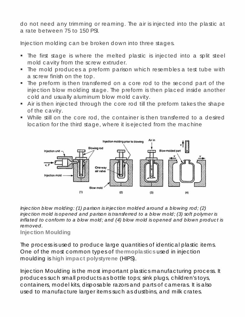
do not need any trimming or reaming. The air is injected into the plastic at a rate between 75 to 150 PSI.
Injection molding can be broken down into three stages.
The first stage is where the melted plastic is injected into a split steel mold cavity from the screw extruder.
The mold produces a preform parison which resembles a test tube with a screw finish on the top.
The preform is then transferred on a core rod to the second part of the injection blow molding stage. The preform is then placed inside another cold and usually aluminum blow mold cavity.
Air is then injected through the core rod till the preform takes the shape of the cavity.
While still on the core rod, the container is then transferred to a desired location for the third stage, where it is ejected from the machine
Injection blow molding: (1) parison is injection molded around a blowing rod; (2) injection mold is opened and parison is transferred to a blow mold; (3) soft polymer is inflated to conform to a blow mold; and (4) blow mold is opened and blown product is removed. Injection Moulding
The process is used to produce large quantities of identical plastic items. One of the most common types of thermoplastics used in injection moulding is high impact polystyrene (HIPS).
Injection Moulding is the most important plastics manufacturing process. It produces such small products as bottle tops; sink plugs, children's toys, containers, model kits, disposable razors and parts of cameras. It is also used to manufacture larger items such as dustbins, and milk crates.
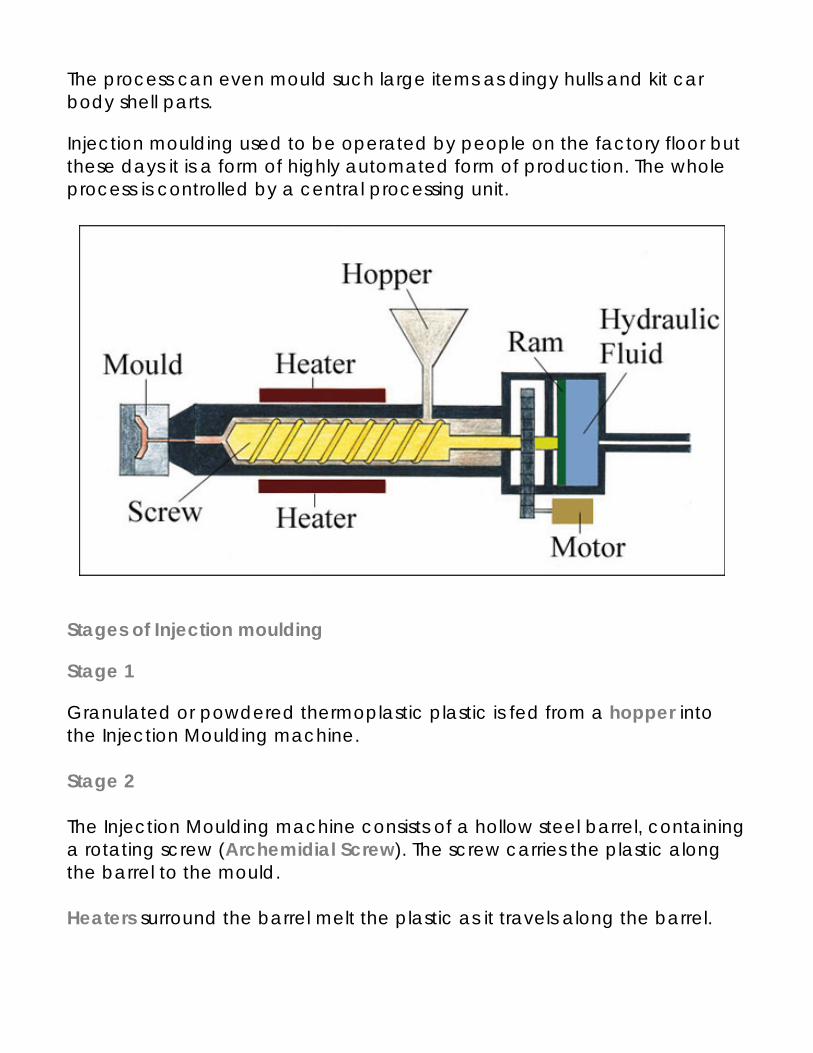
The process can even mould such large items as dingy hulls and kit car body shell parts.
Injection moulding used to be operated by people on the factory floor but these days it is a form of highly automated form of production. The whole process is controlled by a central processing unit.
Stages of Injection moulding
Stage 1
Granulated or powdered thermoplastic plastic is fed from a hopper into the Injection Moulding machine. Stage 2 The Injection Moulding machine consists of a hollow steel barrel, containing a rotating screw (Archemidial Screw). The screw carries the plastic along the barrel to the mould. Heaters surround the barrel melt the plastic as it travels along the barrel.
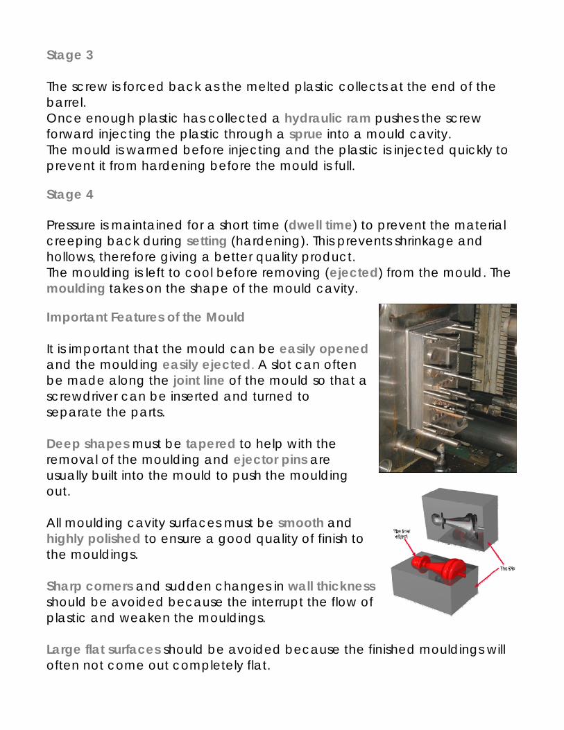
Stage 3 The screw is forced back as the melted plastic collects at the end of the barrel. Once enough plastic has collected a hydraulic ram pushes the screw forward injecting the plastic through a sprue into a mould cavity. The mould is warmed before injecting and the plastic is injected quickly to prevent it from hardening before the mould is full.
Stage 4 Pressure is maintained for a short time (dwell time) to prevent the material creeping back during setting (hardening). This prevents shrinkage and hollows, therefore giving a better quality product. The moulding is left to cool before removing (ejected) from the mould. The moulding takes on the shape of the mould cavity.
Important Features of the Mould It is important that the mould can be easily opened and the moulding easily ejected. A slot can often be made along the joint line of the mould so that a screwdriver can be inserted and turned to separate the parts. Deep shapes must be tapered to help with the removal of the moulding and ejector pins are usually built into the mould to push the moulding out. All moulding cavity surfaces must be smooth and highly polished to ensure a good quality of finish to the mouldings. Sharp corners and sudden changes in wall thickness should be avoided because the interrupt the flow of plastic and weaken the mouldings. Large flat surfaces should be avoided because the finished mouldings will often not come out completely flat.
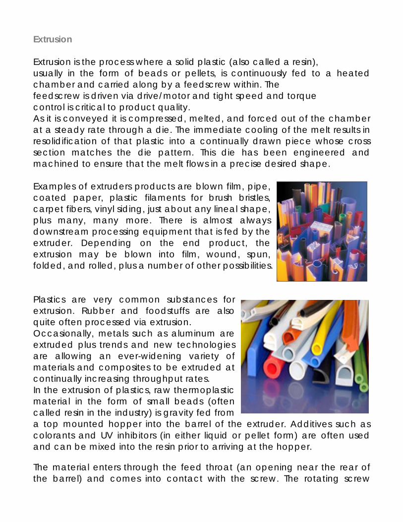
Extrusion Extrusion is the process where a solid plastic (also called a resin), usually in the form of beads or pellets, is continuously fed to a heated chamber and carried along by a feedscrew within. The feedscrew is driven via drive/motor and tight speed and torque control is critical to product quality. As it is conveyed it is compressed, melted, and forced out of the chamber at a steady rate through a die. The immediate cooling of the melt results in resolidification of that plastic into a continually drawn piece whose cross section matches the die pattern. This die has been engineered and machined to ensure that the melt flows in a precise desired shape. Examples of extruders products are blown film, pipe, coated paper, plastic filaments for brush bristles, carpet fibers, vinyl siding, just about any lineal shape, plus many, many more. There is almost always downstream processing equipment that is fed by the extruder. Depending on the end product, the extrusion may be blown into film, wound, spun, folded, and rolled, plus a number of other possibilities. Plastics are very common substances for extrusion. Rubber and foodstuffs are also quite often processed via extrusion. Occasionally, metals such as aluminum are extruded plus trends and new technologies are allowing an ever-widening variety of materials and composites to be extruded at continually increasing throughput rates. In the extrusion of plastics, raw thermoplastic material in the form of small beads (often called resin in the industry) is gravity fed from a top mounted hopper into the barrel of the extruder. Additives such as colorants and UV inhibitors (in either liquid or pellet form) are often used and can be mixed into the resin prior to arriving at the hopper.
The material enters through the feed throat (an opening near the rear of the barrel) and comes into contact with the screw. The rotating screw
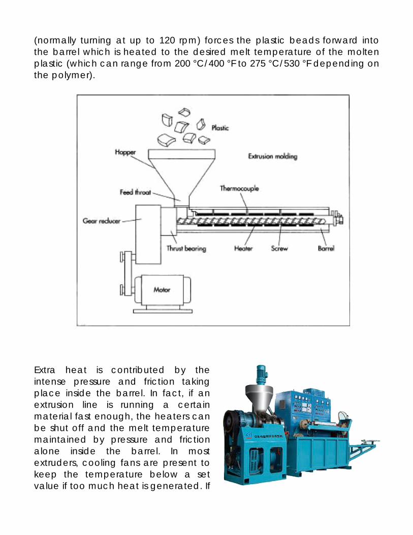
(normally turning at up to 120 rpm) forces the plastic beads forward into the barrel which is heated to the desired melt temperature of the molten plastic (which can range from 200 °C/400 °F to 275 °C/530 °F depending on the polymer).
Extra heat is contributed by the intense pressure and friction taking place inside the barrel. In fact, if an extrusion line is running a certain material fast enough, the heaters can be shut off and the melt temperature maintained by pressure and friction alone inside the barrel. In most extruders, cooling fans are present to keep the temperature below a set value if too much heat is generated. If
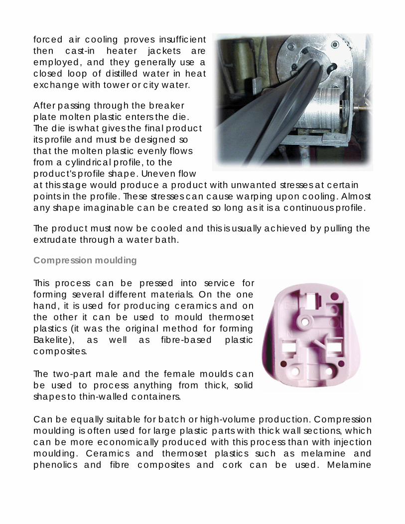
forced air cooling proves insufficient then cast-in heater jackets are employed, and they generally use a closed loop of distilled water in heat exchange with tower or city water.
After passing through the breaker plate molten plastic enters the die. The die is what gives the final product its profile and must be designed so that the molten plastic evenly flows from a cylindrical profile, to the product's profile shape. Uneven flow at this stage would produce a product with unwanted stresses at certain points in the profile. These stresses can cause warping upon cooling. Almost any shape imaginable can be created so long as it is a continuous profile.
The product must now be cooled and this is usually achieved by pulling the extrudate through a water bath.
Compression moulding This process can be pressed into service for forming several different materials. On the one hand, it is used for producing ceramics and on the other it can be used to mould thermoset plastics (it was the original method for forming Bakelite), as well as fibre-based plastic composites. The two-part male and the female moulds can be used to process anything from thick, solid shapes to thin-walled containers. Can be equally suitable for batch or high-volume production. Compression moulding is often used for large plastic parts with thick wall sections, which can be more economically produced with this process than with injection moulding. Ceramics and thermoset plastics such as melamine and phenolics and fibre composites and cork can be used. Melamine
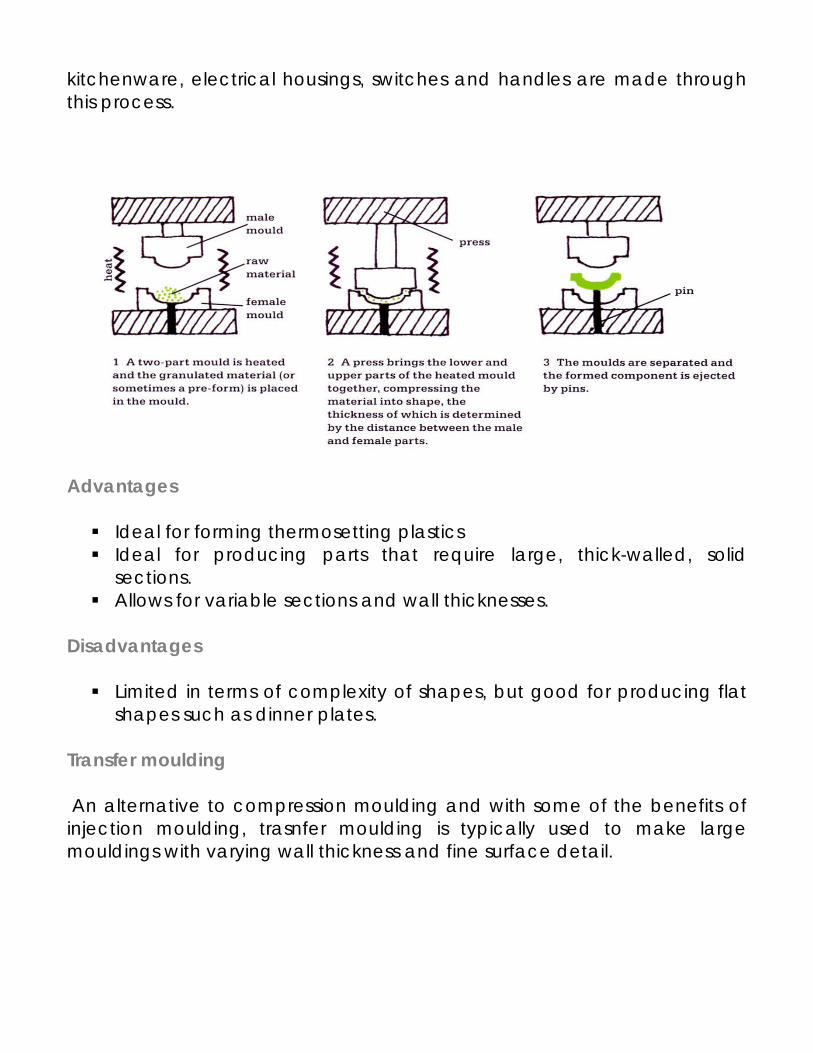
kitchenware, electrical housings, switches and handles are made through this process.
Advantages
Ideal for forming thermosetting plastics Ideal for producing parts that require large, thick-walled, solid
sections. Allows for variable sections and wall thicknesses.
Disadvantages
Limited in terms of complexity of shapes, but good for producing flat shapes such as dinner plates.
Transfer moulding An alternative to compression moulding and with some of the benefits of injection moulding, trasnfer moulding is typically used to make large mouldings with varying wall thickness and fine surface detail.
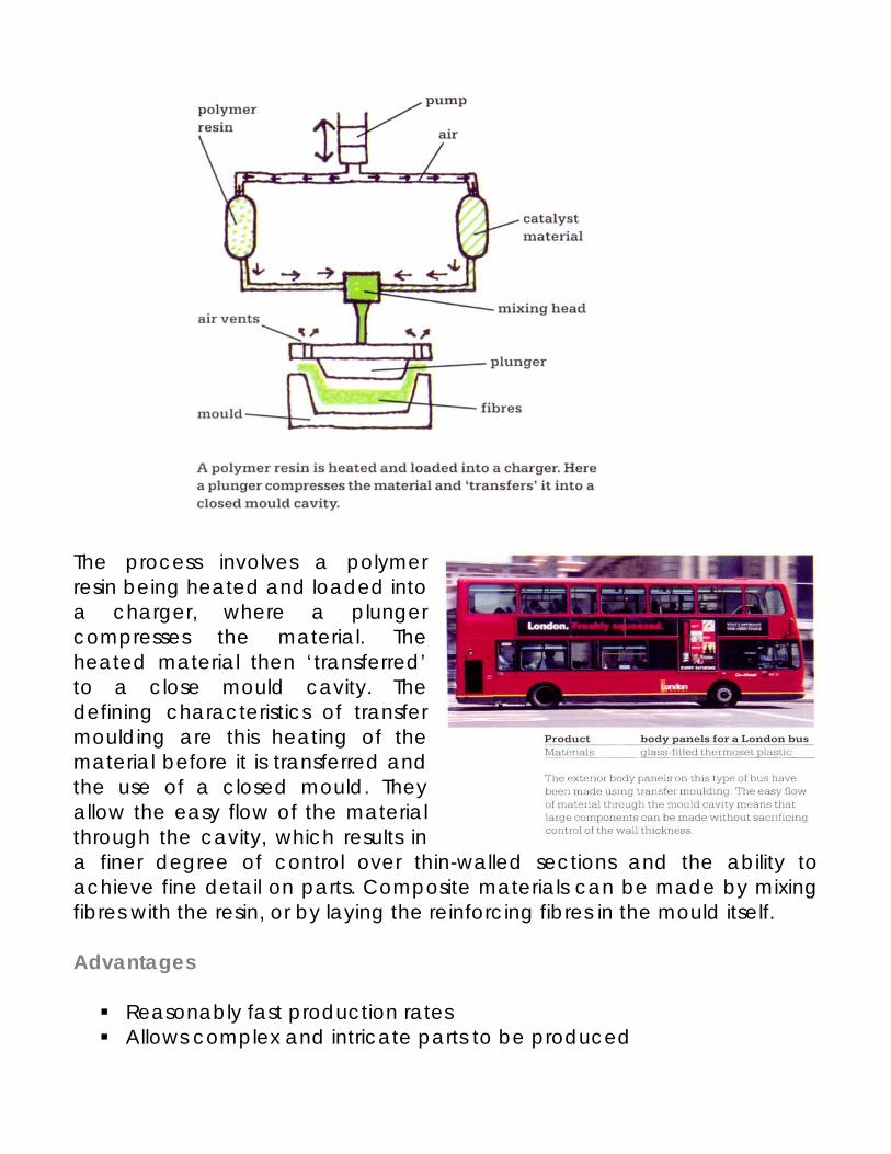
The process involves a polymer resin being heated and loaded into a charger, where a plunger compresses the material. The heated material then ‘transferred’ to a close mould cavity. The defining characteristics of transfer moulding are this heating of the material before it is transferred and the use of a closed mould. They allow the easy flow of the material through the cavity, which results in a finer degree of control over thin-walled sections and the ability to achieve fine detail on parts. Composite materials can be made by mixing fibres with the resin, or by laying the reinforcing fibres in the mould itself. Advantages
Reasonably fast production rates Allows complex and intricate parts to be produced
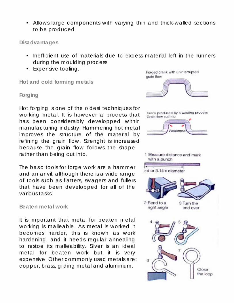
Allows large components with varying thin and thick-walled sections to be produced
Disadvantages
Inefficient use of materials due to excess material left in the runners during the moulding process
Expensive tooling. Hot and cold forming metals Forging Hot forging is one of the oldest techniques for working metal. It is however a process that has been considerably developped within manufacturing industry. Hammering hot metal improves the structure of the material by refining the grain flow. Strenght is increased because the grain flow follows the shape rather than being cut into. The basic tools for forge work are a hammer and an anvil, although there is a wide range of tools such as flatters, swagers and fullers that have been developped for all of the various tasks. Beaten metal work It is important that metal for beaten metal working is malleable. As metal is worked it becomes harder, this is known as work hardening, and it needs regular annealing to restoe its malleability. Silver is an ideal metal for beaten work but it is very expensive. Other commonly used metals are: copper, brass, gilding metal and aluminium.
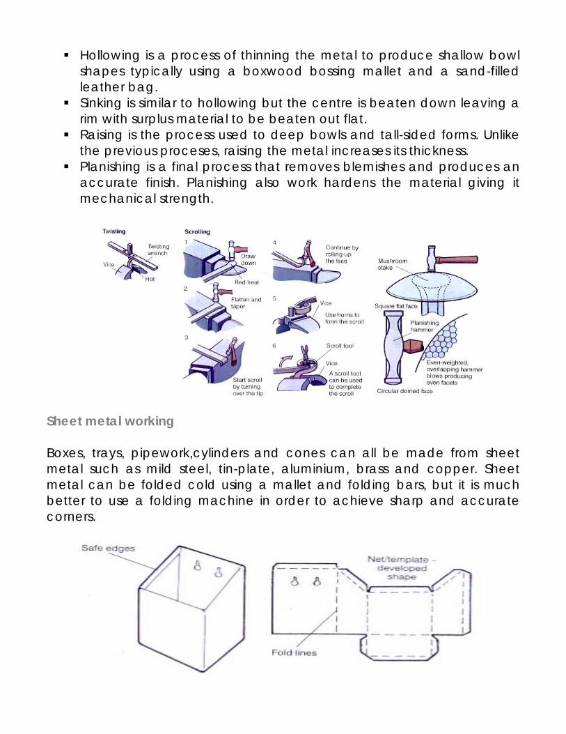
Hollowing is a process of thinning the metal to produce shallow bowl shapes typically using a boxwood bossing mallet and a sand-filled leather bag.
Sinking is similar to hollowing but the centre is beaten down leaving a rim with surplus material to be beaten out flat.
Raising is the process used to deep bowls and tall-sided forms. Unlike the previous proceses, raising the metal increases its thickness.
Planishing is a final process that removes blemishes and produces an accurate finish. Planishing also work hardens the material giving it mechanical strength.
Sheet metal working Boxes, trays, pipework,cylinders and cones can all be made from sheet metal such as mild steel, tin-plate, aluminium, brass and copper. Sheet metal can be folded cold using a mallet and folding bars, but it is much better to use a folding machine in order to achieve sharp and accurate corners.
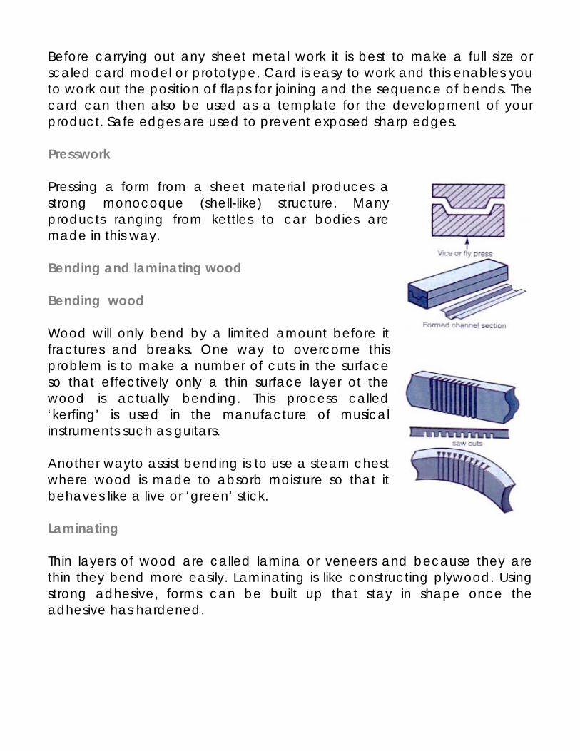
Before carrying out any sheet metal work it is best to make a full size or scaled card model or prototype. Card is easy to work and this enables you to work out the position of flaps for joining and the sequence of bends. The card can then also be used as a template for the development of your product. Safe edges are used to prevent exposed sharp edges. Presswork Pressing a form from a sheet material produces a strong monocoque (shell-like) structure. Many products ranging from kettles to car bodies are made in this way. Bending and laminating wood Bending wood Wood will only bend by a limited amount before it fractures and breaks. One way to overcome this problem is to make a number of cuts in the surface so that effectively only a thin surface layer ot the wood is actually bending. This process called ‘kerfing’ is used in the manufacture of musical instruments such as guitars. Another wayto assist bending is to use a steam chest where wood is made to absorb moisture so that it behaves like a live or ‘green’ stick. Laminating Thin layers of wood are called lamina or veneers and because they are thin they bend more easily. Laminating is like constructing plywood. Using strong adhesive, forms can be built up that stay in shape once the adhesive has hardened.
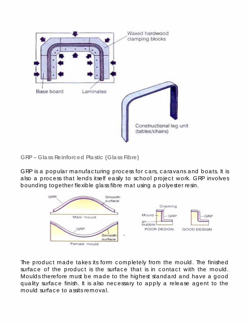
GRP – Glass Reinforced Plastic (Glass Fibre) GRP is a popular manufacturing process for cars, caravans and boats. It is also a process that lends itself easily to school project work. GRP involves bounding together flexible glass fibre mat using a polyester resin. The product made takes its form completely from the mould. The finished surface of the product is the surface that is in contact with the mould. Moulds therefore must be made to the highest standard and have a good quality surface finish. It is also necessary to apply a release agent to the mould surface to assits removal.
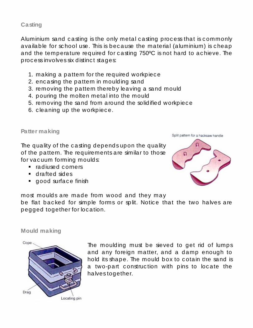
Casting Aluminium sand casting is the only metal casting process that is commonly available for school use. This is because the material (aluminium) is cheap and the temperature required for casting 750ºC is not hard to achieve. The process involves six distinct stages:
1. making a pattern for the required workpiece 2. encasing the pattern in moulding sand 3. removing the pattern thereby leaving a sand mould 4. pouring the molten metal into the mould 5. removing the sand from around the solidified workpiece 6. cleaning up the workpiece.
Patter making The quality of the casting depends upon the quality of the pattern. The requirements are similar to those for vacuum forming moulds:
radiused corners drafted sides good surface finish
most moulds are made from wood and they may be flat backed for simple forms or split. Notice that the two halves are pegged together for location. Mould making
The moulding must be sieved to get rid of lumps and any foreign matter, and a damp enough to hold its shape. The mould box to cotain the sand is a two-part construction with pins to locate the halves together.
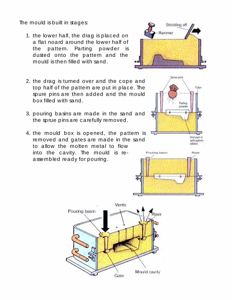
The mould is built in stages:
1. the lower half, the drag is placed on a flat noard around the lower half of the pattern. Parting powder is dusted onto the pattern and the mould is then filled with sand.
2. the drag is turned over and the cope and top half of the pattern are put in place. The spure pins are then added and the mould box filled with sand.
3. pouring basins are made in the sand and
the sprue pins are carefully removed.
4. the mould box is opened, the pattern is removed and gates are made in the sand to allow the molten metal to flow into the cavity. The mould is re-assembled ready for pouring.
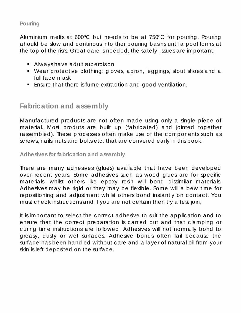
Pouring Aluminium melts at 600ºC but needs to be at 750ºC for pouring. Pouring ahould be slow and continous into ther pouring basins until a pool forms at the top of the risrs. Great care is needed, the satefy issues are important.
Always have adult supercision Wear protective clothing: gloves, apron, leggings, stout shoes and a
full face mask Ensure that there is fume extraction and good ventilation.
Fabrication and assembly Manufactured products are not often made using only a single piece of material. Most produts are built up (fabricated) and jointed together (assembled). These processes often make use of the components such as screws, nails, nuts and bolts etc. that are convered early in this book. Adhesives for fabrication and assembly There are many adhesives (glues) available that have been developed over recent years. Some adhesives such as wood glues are for specific materials, whilst others like epoxy resin will bond dissimilar materials. Adhesives may be rigid or they may be flexible. Some will alloew time for repositioning and adjustment whilst others bond instantly on contact. You must check instructions and if you are not certain then try a test join, It is important to select the correct adhesive to suit the application and to ensure that the correct preparation is carried out and that clamping or curing time instructions are followed. Adhesives will not normally bond to greasy, dusty or wet surfaces. Adhesive bonds often fail because the surface has been handled without care and a layer of natural oil from your skin is left deposited on the surface.
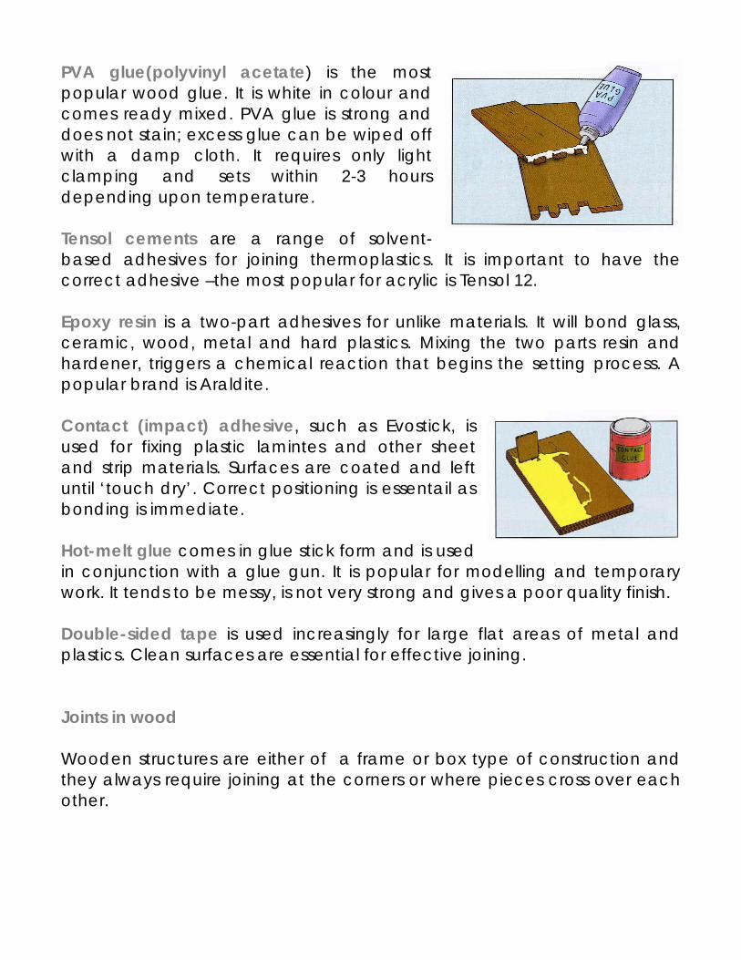
PVA glue(polyvinyl acetate) is the most popular wood glue. It is white in colour and comes ready mixed. PVA glue is strong and does not stain; excess glue can be wiped off with a damp cloth. It requires only light clamping and sets within 2-3 hours depending upon temperature. Tensol cements are a range of solvent-based adhesives for joining thermoplastics. It is important to have the correct adhesive –the most popular for acrylic is Tensol 12. Epoxy resin is a two-part adhesives for unlike materials. It will bond glass, ceramic, wood, metal and hard plastics. Mixing the two parts resin and hardener, triggers a chemical reaction that begins the setting process. A popular brand is Araldite. Contact (impact) adhesive, such as Evostick, is used for fixing plastic lamintes and other sheet and strip materials. Surfaces are coated and left until ‘touch dry’. Correct positioning is essentail as bonding is immediate. Hot-melt glue comes in glue stick form and is used in conjunction with a glue gun. It is popular for modelling and temporary work. It tends to be messy, is not very strong and gives a poor quality finish. Double-sided tape is used increasingly for large flat areas of metal and plastics. Clean surfaces are essential for effective joining. Joints in wood Wooden structures are either of a frame or box type of construction and they always require joining at the corners or where pieces cross over each other.
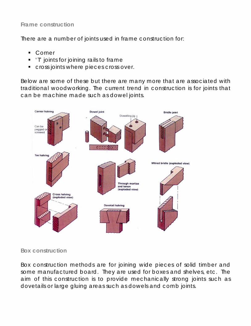
Frame construction There are a number of joints used in frame construction for:
Corner ‘T’ joints for joining rails to frame cross joints where pieces cross over.
Below are some of these but there are many more that are associated with traditional woodworking. The current trend in construction is for joints that can be machine made such as dowel joints. Box construction Box construction methods are for joining wide pieces of solid timber and some manufactured board. They are used for boxes and shelves, etc. The aim of this construction is to provide mechanically strong joints such as dovetails or large gluing areas such as dowels and comb joints.
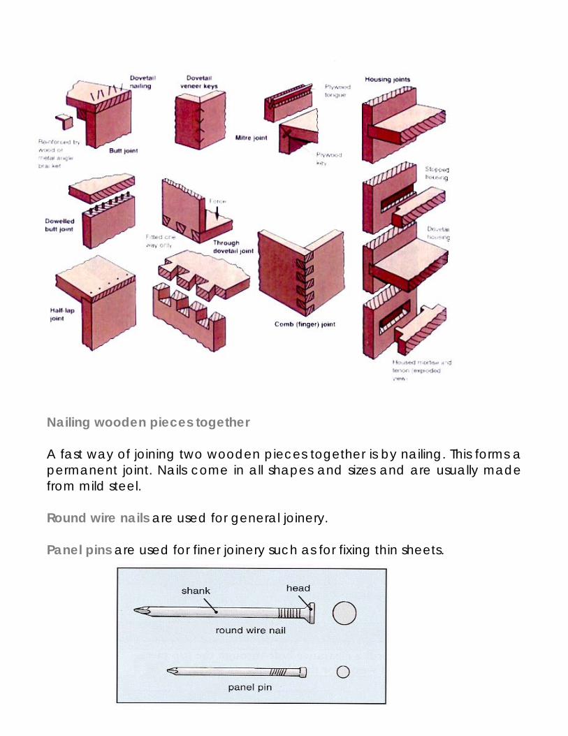
Nailing wooden pieces together A fast way of joining two wooden pieces together is by nailing. This forms a permanent joint. Nails come in all shapes and sizes and are usually made from mild steel. Round wire nails are used for general joinery. Panel pins are used for finer joinery such as for fixing thin sheets.
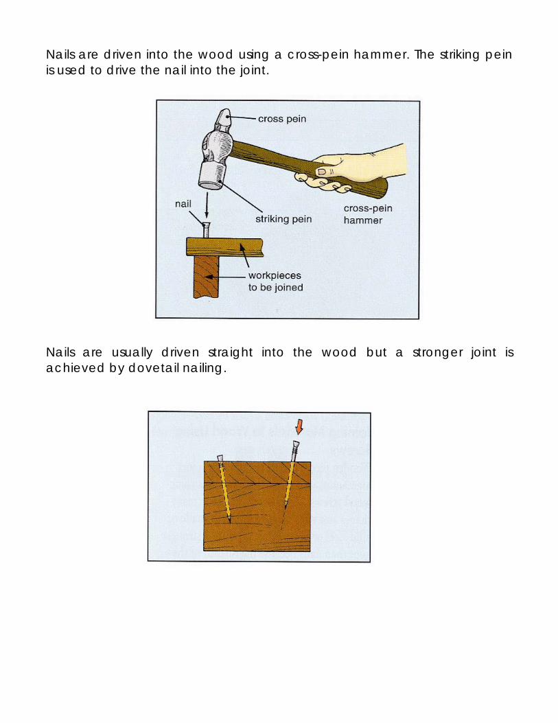
Nails are driven into the wood using a cross-pein hammer. The striking pein is used to drive the nail into the joint. Nails are usually driven straight into the wood but a stronger joint is achieved by dovetail nailing.
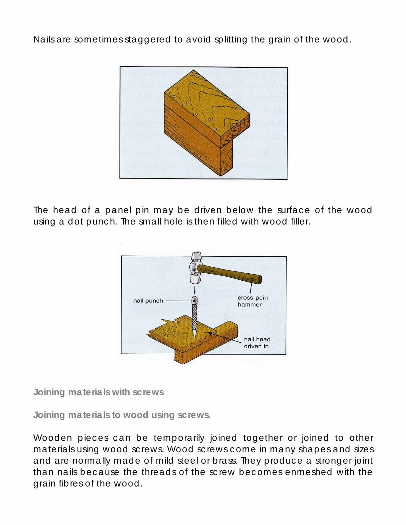
Nails are sometimes staggered to avoid splitting the grain of the wood. The head of a panel pin may be driven below the surface of the wood using a dot punch. The small hole is then filled with wood filler. Joining materials with screws Joining materials to wood using screws. Wooden pieces can be temporarily joined together or joined to other materials using wood screws. Wood screws come in many shapes and sizes and are normally made of mild steel or brass. They produce a stronger joint than nails because the threads of the screw becomes enmeshed with the grain fibres of the wood.

Two common types of wood screw are the countersunk head screw and the round head screw. Countersunk head screw are used in joints where the screw heads are used in joints where the screw heads must be flush with the surface. Hinges and handles are normally fixed in place using countersunk head screws. Round head screws are used in joints where the head of the screw does not need to be flush with the surface. Joining metals and plastics with screws Metal and plastics workpieces can be joined together temporarily using screws. Machine screws are available in a range of diameters and can be fastened directly into the pilot hole of the material.
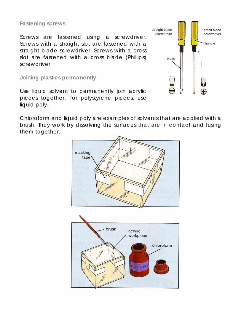
Fastening screws Screws are fastened using a screwdriver. Screws with a straight slot are fastened with a straight blade screwdriver. Screws with a cross slot are fastened with a cross blade (Phillips) screwdriver. Joining plastics permanently Use liquid solvent to permanently join acrylic pieces together. For polystyrene pieces, use liquid poly. Chloroform and liquid poly are examples of solvents that are applied with a brush. They work by dissolving the surfaces that are in contact and fusing them together.
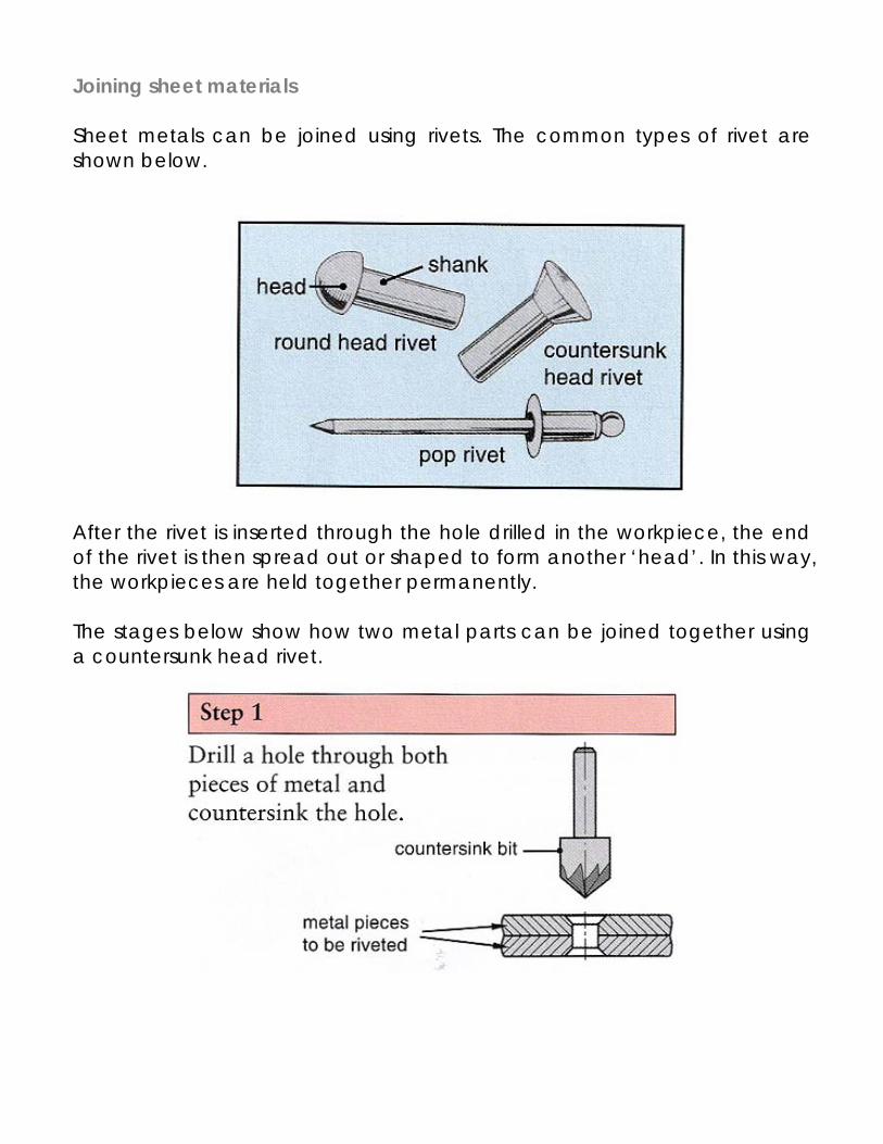
Joining sheet materials Sheet metals can be joined using rivets. The common types of rivet are shown below. After the rivet is inserted through the hole drilled in the workpiece, the end of the rivet is then spread out or shaped to form another ‘head’. In this way, the workpieces are held together permanently. The stages below show how two metal parts can be joined together using a countersunk head rivet.
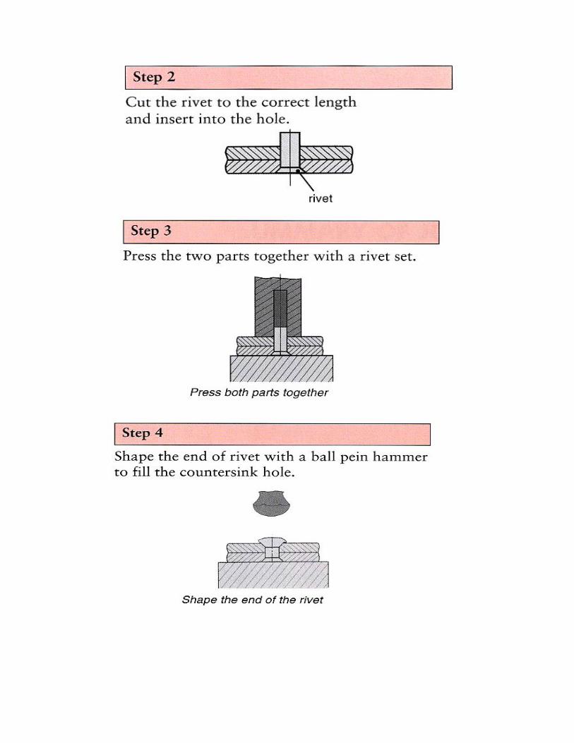
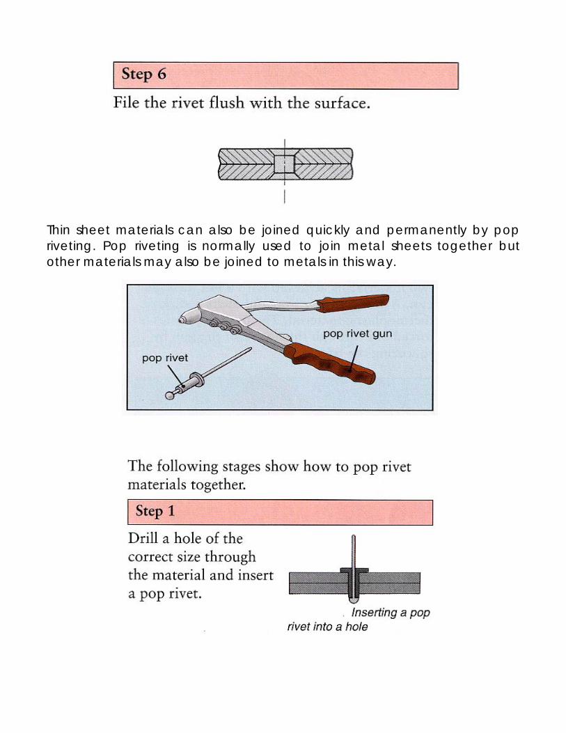
Thin sheet materials can also be joined quickly and permanently by pop riveting. Pop riveting is normally used to join metal sheets together but other materials may also be joined to metals in this way.
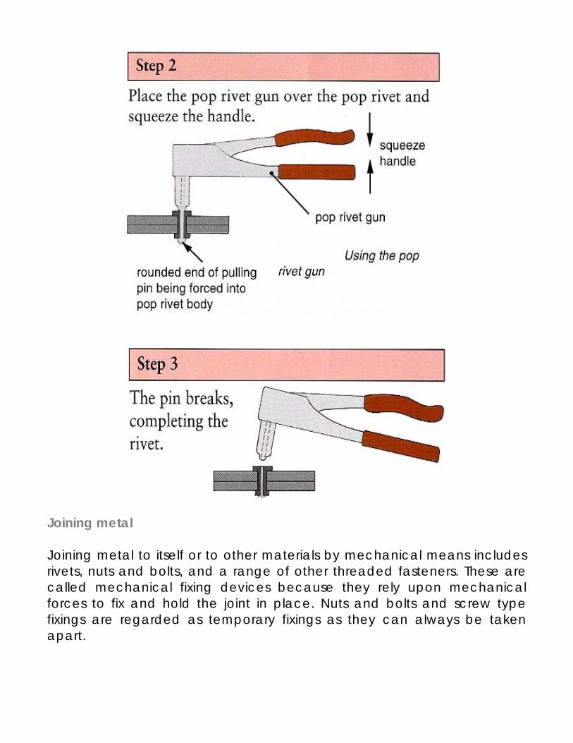
Joining metal Joining metal to itself or to other materials by mechanical means includes rivets, nuts and bolts, and a range of other threaded fasteners. These are called mechanical fixing devices because they rely upon mechanical forces to fix and hold the joint in place. Nuts and bolts and screw type fixings are regarded as temporary fixings as they can always be taken apart.
Heat processes – soldering and brazing Soldering is a process that affects a joint by introducing another metal to the surface of the metal to be joined; this is called ‘local alloying’. The solder actually becomes part of the surface of the material and forms a permanent joint. There are a wide range of solders that have different strenghts and melting points. For all soldering processes joints must be prepared and cleaned and the correct flux used. Flux is a chemical cleaning agent. Soft solder is the weakest solder and has the lowest melting point. It is used mainly for electrical work and joints in tin-plate. Soft soldering can be carried out using either a flame or a soldering iron. It is an alloy of tin and lead. Use resin flux for soft soldering. Silver solders are hard solders and have melting points in the range 625ºC - 800ºC. They are used for many beaten metal work applications. Silver soldering is carried out using either a brazing hearth or an oxy-acetylene flame. Silver solders are alloys of copper and zinc with some added silver. Use ‘easy-flo’ flux for silver soldering. Brazing is the hardest form of hard solder and melts at the highest temperature, 875ºC. this is too hot for brass and copper work but ideal for mild steel. Brazing spelter, the rod used for brazing, is an alloy of copper and zinc. Use borax flux for brazing. Making soldered joints Joints must be prepared and held securely in place for all soldering processes. Joints will always be stronger if they have a mechanical strength built into them such as interlocking or slotting together. Fire bricks should be used around joints to retain and concentrate the heat from the flame.
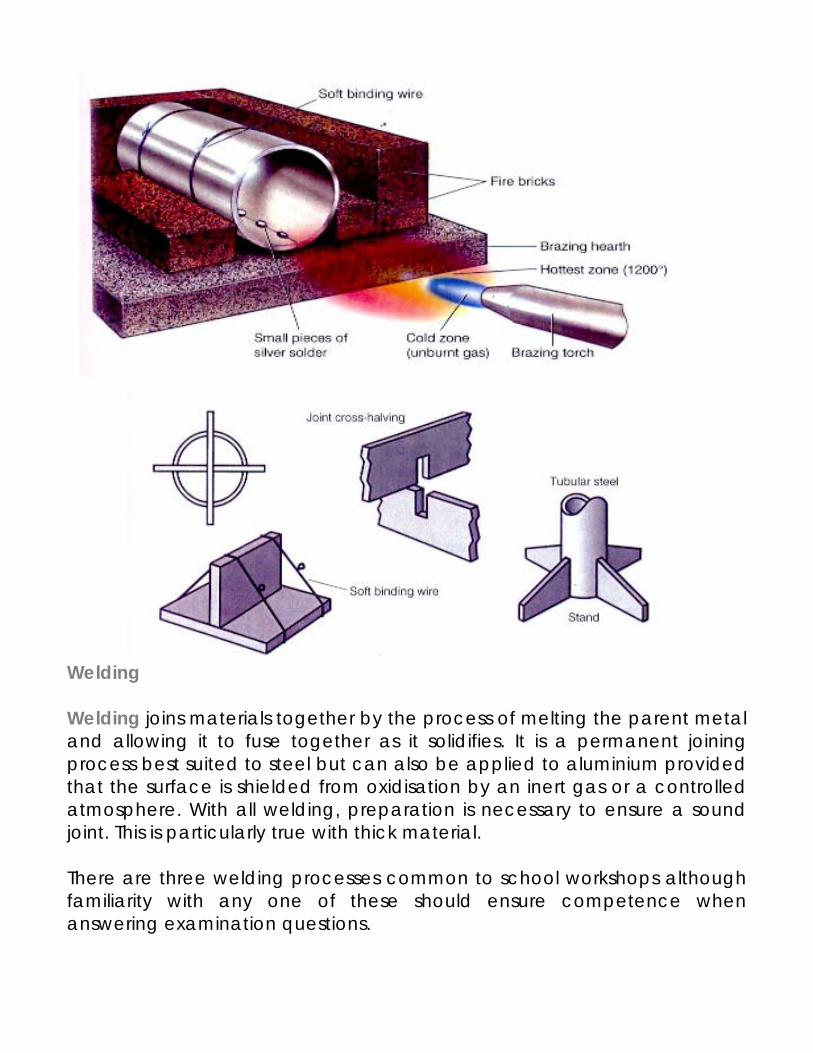
Welding Welding joins materials together by the process of melting the parent metal and allowing it to fuse together as it solidifies. It is a permanent joining process best suited to steel but can also be applied to aluminium provided that the surface is shielded from oxidisation by an inert gas or a controlled atmosphere. With all welding, preparation is necessary to ensure a sound joint. This is particularly true with thick material. There are three welding processes common to school workshops although familiarity with any one of these should ensure competence when answering examination questions.
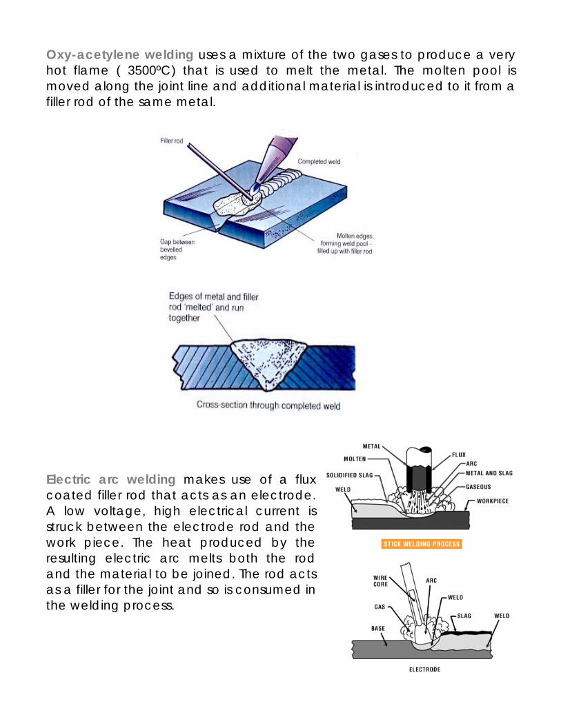
Oxy-acetylene welding uses a mixture of the two gases to produce a very hot flame ( 3500ºC) that is used to melt the metal. The molten pool is moved along the joint line and additional material is introduced to it from a filler rod of the same metal. Electric arc welding makes use of a flux coated filler rod that acts as an electrode. A low voltage, high electrical current is struck between the electrode rod and the work piece. The heat produced by the resulting electric arc melts both the rod and the material to be joined. The rod acts as a filler for the joint and so is consumed in the welding process.
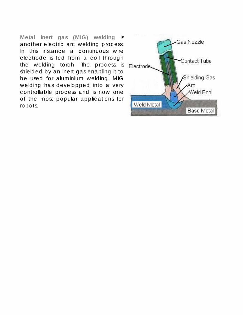
Metal inert gas (MIG) welding is another electric arc welding process. In this instance a continuous wire electrode is fed from a coil through the welding torch. The process is shielded by an inert gas enabling it to be used for aluminium welding. MIG welding has developped into a very controllable process and is now one of the most popular applications for robots.