Embed Size (px)
Citation preview

IGCNewsletter
ISSN 0972-5741 Volume 90 October 2011
IGCNewsletter
ISSN 0972-5741 Volume 94 October 2012
INDIRA GANDHI CENTRE FOR ATOMIC RESEARCHhttp://www.igcar.gov.in/lis/nl94/igc94.pdf
IN THIS ISSUE
Technical Articles
•Exploring Distinct Amorphous States in Materials
•Launching of e-Tendering in Civil Engineering Group
Young Officer’s Forum
• Design and Development of Soft-Core Processor based Remote Terminal Units for Fast Breeder Reactors
Young Researcher’s Forum
• Applications of Ionic Liquids at the Back End of Nuclear Fuel Cycle
News and Events
• BITS Practice School
• Summer Training in Physics and Chemistry - 2012
• Graduation Function of the Sixth Batch of Trainee Scientific Officers of BARC Training School at IGCAR
• Annual Meet of Quality Circle - 2012 Forthcoming Meeting / Conference
• Structure and Thermodynamics of Emerging Materials (STEM - 2012)
• Conference on Recent Trends in Computer and Networking Technologies (Sangoshthi - 2012)
• 24th Annual General Meeting Materials Research Society of India (MRSI-AGM2013) Kalpakkam
Visit of Dignitaries
Awards & Honours

From the EditorDear Reader I am happy to forward a copy of the latest issue of IGC Newsletter (Volume 94, October 2012 issue).
In the Director’s Desk, Shri S. C. Chetal, Director, IGCAR has highlighted the contributions made by the Fast Reactor Technology Group towards the development of devices and testing of various components for PFBR. The expertise gained by the group in sodium handling and sodium system operation through the successful establishment of major sodium facilities such as steam generator test facility, large component test rig, INSOT facilities and the SADHANA loop have been discussed.
In the first technical article Dr. A. K. Arora has explored the amorphous states of zirconium tungstate and vanadium pentaoxide by in-situ high pressure Raman scattering and synchrotron X-ray diffraction studies. The studies reveal an amorphous to amorphous transition in zirconium tungstate and an irreversible amorphization for vanadium pentaoxide.
In the second technical article, Shri C. Sivathanu Pillai has discussed on the launching of e-tendering including e-quoting required for the development of infrastructure for the various R&D programmes of the Centre.
In the young officer’s forum, Aditya Gour describes the design and development of a soft-core processor based remote terminal unit for Fast Breeder Reactors.
Alok Rout has described the synthesis of a couple of room temperature ionic liquids and studied the separation of actinides and fission products in nitric acid medium, in the young researcher’s forum.
This newsletter carries reports on the Summer Training in Physics and Chemistry-2012, Graduation function of the Sixth batch of Trainee Scientific Officers of BARC Training School at IGCAR, BITS Practice School and on the Annual Meet of Quality Circle.
Shri S. K. Chande, Vice-Chairman, Atomic Energy Regulatory Board and Prof. Bala Balachandran, Founder and Dean, Prof. S. Sriram, Executive Director from Great Lakes Institute of Management, Chennai visited the Centre during the last quarter.
We are happy to share with you the awards, honours and distinctions earned by our colleagues. We look forward to your comments, continued guidance and support.
With my best wishes and personal regards,
(M. Sai Baba)Chairman, Editorial Committee, IGC Newsletter &Associate Director, Resources Management Group
IGC Newsletter From the Editor

IGC Newsletter
1
Director’s Desk
INTRODUCTION
Mastering of fast reactor technology is very important for the successful implementation of second stage of Indian nuclear power programme. Due to excellent neutronic, physical and thermal characteristics, liquid sodium is the coolant of choice for fast breeder reactors. As part of Fast Breeder Reactor (FBR) development programme, a comprehensive indigenous research and development programme has been pursued in sodium technology at IGCAR. As the operating conditions in fast reactors are highly demanding, design of components and their testing is quite a challenge. To have hands on experience in sodium technology, Reactor Engineering Laboratory was set-up in 1971. The 500 kW sodium facility in Engineering Hall-I was the first sodium loop commissioned with an objective of gaining experience in handling of sodium, conducting studies related to heat transfer, testing of instrumentation system besides providing platform for training of personnel for FBTR operation. The scope of Reactor Engineering Laboratory has diversified and it has grown into the present Fast Reactor Technology Group (FRTG). FRTG is now responsible for development and testing of components for Prototype Fast Breeder Reactor (PFBR), thermal hydraulics studies in support of PFBR and development of advanced instrumentation techniques. Expertise in handling sodium and operation of sodium systems has been developed. Currently, there are around ten sodium facilities in operation to cater to the various experimental and testing requirements of PFBR and future FBRs. In this article, I have focused more on the development and testing of critical components of PFBR and experiments conducted in water and sodium facilities.
TESTING OF PFBR COMPONENTS
Testing of components is as important as designing them. As the designed life of the reactor is forty years, the performance
of major components play a crucial role in enhancing the uptime of the plant. Absorber rod drive mechanisms, fuel handling machines, sodium level sensors, electromagnetic pumps, eddy current flow meters and under sodium ultrasonic scanner are tested in various facilities of FRTG.
Shut Down Mechanisms
The first shut down system of PFBR consists of Control and Safety Rod (CSR), the moveable absorber rod having boron carbide (B4C) as neutron absorbing material, in conjunction with Control and Safety Drive Mechanism (CSRDM) to lift and drop the CSR in the core. There are nine CSR and CSRDMs which are used for controlling the reactor power and shutting down the reactor. The second shut down system consists of Diverse Safety Rod (DSR), the moveable absorber rod having boron carbide as neutron absorbing material along with Diverse Safety Rod Drive Mechanism (DSRDM) to lift and drop the DSR from the core. There are three DSRDMs for shutting down the reactor during a SCRAM. In both the shut down systems electromagnet is used to hold the absorber rod at operating position when reactor is in power and de-energization of electromagnet causes the absorber rod to drop into the core under gravity resulting in shutting down of the reactor. Both the systems were qualified in FRTG by testing them in air and sodium. The CSR and CSRDM were qualified in two stages of extensive testing. In the first stage, the critical assemblies/components of the mechanism, namely scram release electromagnet, hydraulic dashpot and dynamic seals etc. were tested and qualified individually and the design parameters were fine tuned. In the second stage, prototype CSR and CSRDM were manufactured and subjected to functional tests in air, hot argon (at 473 K) and subsequently in sodium at temperatures ranging from 473-823 K. Extensive testing of mechanism in aligned as well as misaligned condition was carried out and
Progress in Sodium Technology

IGC Newsletter
2
after the successful completion of functional testing, endurance testing was carried out. CSR of PFBR is qualified for its full life (of two years) in reactor and CSRDM for fourteen years. For DSR and DSRDM, scram release electromagnet tests were carried out in ambient air, in a furnace and in sodium. Electromagnet was also tested for 1000 thermal shocks and qualified. Functional testing and endurance testing of DSR and DSRDM were completed and the DSR is qualified for its full life (of two years) and DSRDM for ten years. Nine CSRDMs and three DSRDMs required for first criticality of PFBR after testing at FRTG were delivered to BHAVINI.
Fuel Handling Machines
Transfer arm and inclined fuel transfer machine are the two fuel handling machines deployed in PFBR for transferring the sub-assemblies within the core and into and out of the reactor respectively. Performance testing of these machines are to be carried out in the reactor simulated conditions before erecting them in the reactor. Testing is restricted to 10% of the total number of cycles expected in the reactor life of forty years. These mechanisms are heavy and consist of several parts operating with close tolerances, making assembly a challenging task.
Transfer Arm
Transfer arm (Figure 1a) is the fuel handling machine of PFBR required to transfer core sub-assemblies within the core, storage location and the in-vessel transfer position in the reactor. Transfer arm manufactured by an Indian industry was assembled in the Large Component Test Rig (LCTR) and functional testing of transfer arm in air for 200 cycles of operation was completed. Functional testing of transfer arm in air for 20 cycles at room temperature and at elevated temperatures of 293, 313, 333, 358, 383 and 393 K were carried out in Test Vessel-5. In-sodium
testing of the transfer arm to check its performance in reactor conditions is currently being taken up.
In-vessel Fuel Transfer Machine
Primary ramp and primary tilting mechanism are the critical components of the inclined fuel transfer machine (IFTM). Performance testing of primary ramp and primary tilting mechanism (Figure 1b) was carried out successfully at LCTR of FRTG. The test set-up consists of transfer pot with dummy sub-assembly, ramp extension piece and simplified hoisting system with control console. 600 cycles of testing which involves raising and lowering of the transfer pot between primary tilting mechanism and ramp extension piece was completed. Initially, 100 cycles were carried out in air at room temperature and in hot air followed by sodium testing at 473 K. The effect of reactor operation at rated condition of temperature on the system performance was also simulated by introducing two dwell periods of 150 hours each at 820 K. Overall performance of the system was satisfactory. After testing, the component was cleaned by CO2-water vapor process to remove sodium from surfaces. No rubbing or scoring marks were observed during post test inspection and surface examination revealed no cracks on the hard faced surfaces. The mechanisms were cleaned and transported to BHAVINI.
Sodium Level Sensors
Sodium level measurement in primary and secondary circuits of PFBR is carried out by means of mutual inductance based continuous and discrete level probes. These probes were designed by IGCAR (Figure 2) and manufactured with the support of industry. Mutual inductance level probe works on the principle of decrease in mutual inductance of the probe with increase in
Figure 1: (a) Assembly of transfer arm at LCTR (b) Primary tilting mechanism
From the Director's Desk
Figure 2: Continuous type mutual inductances level probe
a) b)

IGC Newsletter
3
sodium level. The primary winding is excited with a constant current and secondary output voltage will decrease with increase in sodium level. There are twenty nine numbers each of continuous type and discontinuous type mutual inductance level probes of lengths varying from 0.66-9.6 metres at various locations in PFBR. Calibration of these probes in sodium at the operating temperature ranging from 553-823 K was completed. During calibration, the continuous level sensors were characterized to find out the optimum operating frequency and the resistance to be connected across secondary winding for temperature compensation. All level probes after calibration and testing have been delivered to BHAVINI for installation and commissioning.
Electromagnetic Pumps
Electromagnetic pumps for pumping high temperature liquid sodium in the reactor systems/experimental facilities have been developed. The electrical conductivity property of sodium is exploited in electromagnetic pump which works on Faraday’s law. These pumps are maintenance-free as there are no moving parts. All the electromagnetic pumps used in PFBR as well as sodium loops in FRTG are designed in-house. FRTG has developed annular linear induction pump (Figure 3) of capacity 5-170 m3/h and head upto 4 kg/cm2 and the same was tested successfully in sodium loop. The 170 m3/h annular linear induction pump has logged around 20,000 hours of operation in Steam Generator Test Facility. Submersible type DC conduction pump to be used in Failed Fuel Location Module of PFBR is also developed in-house.
Eddy Current Flow Meters
Sodium flow measurement in core sub-assemblies of FBRs, facilitates the detection of flow blockage in the sub-assemblies. Eddy current flow meters for flow measurements in core sub-assemblies and primary sodium pumps of PFBR are designed and developed in-house (Figure 4). The probes were tested and calibrated in sodium and their performance was found to be excellent. Two core flow monitoring mechanisms with eddy current flow sensors for PFBR central canal and observation port were manufactured and their performance testing is in progress.
Under Sodium Ultrasonic Scanner
Under sodium examination as part of in-service inspection is yet another challenge in sodium cooled FBRs. As liquid sodium is opaque, under sodium ultrasonic scanner (Figure 5) using high
Figure 3: Annular linear induction pump Figure 4: Eddy current flow sensor for PFBR
From the Director's Desk
Figure 5: Under sodium ultrasonic scanner
IGC Newsletter
4
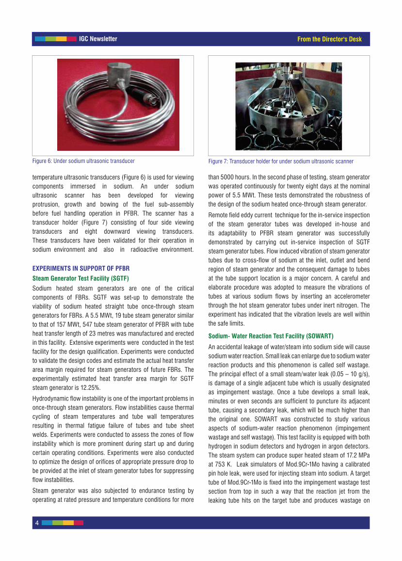
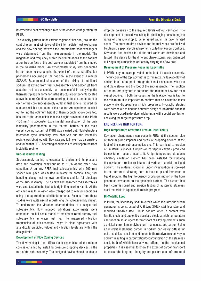
temperature ultrasonic transducers (Figure 6) is used for viewing components immersed in sodium. An under sodium ultrasonic scanner has been developed for viewing protrusion, growth and bowing of the fuel sub-assembly before fuel handling operation in PFBR. The scanner has a transducer holder (Figure 7) consisting of four side viewing transducers and eight downward viewing transducers. These transducers have been validated for their operation in sodium environment and also in radioactive environment.
EXPERIMENTS IN SUPPORT OF PFBR
Steam Generator Test Facility (SGTF)
Sodium heated steam generators are one of the critical components of FBRs. SGTF was set-up to demonstrate the viability of sodium heated straight tube once-through steam generators for FBRs. A 5.5 MWt, 19 tube steam generator similar to that of 157 MWt, 547 tube steam generator of PFBR with tube heat transfer length of 23 metres was manufactured and erected in this facility. Extensive experiments were conducted in the test facility for the design qualification. Experiments were conducted to validate the design codes and estimate the actual heat transfer area margin required for steam generators of future FBRs. The experimentally estimated heat transfer area margin for SGTF steam generator is 12.25%.
Hydrodynamic flow instability is one of the important problems in once-through steam generators. Flow instabilities cause thermal cycling of steam temperatures and tube wall temperatures resulting in thermal fatigue failure of tubes and tube sheet welds. Experiments were conducted to assess the zones of flow instability which is more prominent during start up and during certain operating conditions. Experiments were also conducted to optimize the design of orifices of appropriate pressure drop to be provided at the inlet of steam generator tubes for suppressing flow instabilities.
Steam generator was also subjected to endurance testing by operating at rated pressure and temperature conditions for more
than 5000 hours. In the second phase of testing, steam generator was operated continuously for twenty eight days at the nominal power of 5.5 MWt. These tests demonstrated the robustness of the design of the sodium heated once-through steam generator.
Remote field eddy current technique for the in-service inspection of the steam generator tubes was developed in-house and its adaptability to PFBR steam generator was successfully demonstrated by carrying out in-service inspection of SGTF steam generator tubes. Flow induced vibration of steam generator tubes due to cross-flow of sodium at the inlet, outlet and bend region of steam generator and the consequent damage to tubes at the tube support location is a major concern. A careful and elaborate procedure was adopted to measure the vibrations of tubes at various sodium flows by inserting an accelerometer through the hot steam generator tubes under inert nitrogen. The experiment has indicated that the vibration levels are well within the safe limits.
Sodium- Water Reaction Test Facility (SOWART)
An accidental leakage of water/steam into sodium side will cause sodium water reaction. Small leak can enlarge due to sodium water reaction products and this phenomenon is called self wastage. The principal effect of a small steam/water leak (0.05 – 10 g/s), is damage of a single adjacent tube which is usually designated as impingement wastage. Once a tube develops a small leak, minutes or even seconds are sufficient to puncture its adjacent tube, causing a secondary leak, which will be much higher than the original one. SOWART was constructed to study various aspects of sodium-water reaction phenomenon (impingement wastage and self wastage). This test facility is equipped with both hydrogen in sodium detectors and hydrogen in argon detectors. The steam system can produce super heated steam of 17.2 MPa at 753 K. Leak simulators of Mod.9Cr-1Mo having a calibrated pin hole leak, were used for injecting steam into sodium. A target tube of Mod.9Cr-1Mo is fixed into the impingement wastage test section from top in such a way that the reaction jet from the leaking tube hits on the target tube and produces wastage on
From the Director's Desk
Figure 6: Under sodium ultrasonic transducer Figure 7: Transducer holder for under sodium ultrasonic scanner

IGC Newsletter
5
its surface. Six self wastage experiments and nine impingement wastage experiments were carried out for understanding the behavior of leak propagation and data generation. The wastage resistance of Mod.9Cr-1Mo steel is experimentally validated and found to be better than that of 2.25Cr-1Mo steel.
Safety Grade Decay Heat Removal (SGDHR) Studies
The effectiveness of the fully passive PFBR decay heat removal system was successfully demonstrated by experiments with water in different facilities and with sodium in SADHANA facility. Experimental studies with water were carried out to understand core-hot pool-decay heat exchanger interaction during SGDHR operation in scaled models of the PFBR. SAMRAT model experiments have shown that all the proposed heat transport paths have influence on core cooling. Flow visualization studies in a slab model of the reactor pool (carried out at FCRI, Palghat) have shown that inter wrapper flow contribution is 25% of the total heat removal capacity during SGDHR operation.
SADHANA (Figure 8) a sodium facility, has been successfully commissioned for demonstrating natural convection heat removal capability of SGDHR system of PFBR. This facility is a scaled down model of the PFBR SGDHR system with a capacity of 355 kW and the height difference between the thermal centers of decay heat exchanger and sodium to air heat exchanger is 19.5 metres. Performance of SGDHR system under steady state, transients and some of the off normal conditions were studied in this facility. These studies experimentally demonstrated the adequacy of PFBR SGDHR system.
Thermal Hydraulics Experiments
The thermal hydraulic characteristics of reactor pool and different components of the reactor are analyzed both by computational tools and through experimental validations using different simulant fluids. A comprehensive experimental programme encompassing areas of fluid flow, heat transfer and flow induced vibration pursued at FRTG has generated important data for qualification of the reactor components design and validation of the computational tools. Experiments have been conducted in sodium, water and in air. Models of varying scale sizes and large test facilities have been set-up to aid in the conduct of these studies.
SAMRAT Model
To have insight into the complexities of the thermal hydraulic behaviour of the pool of PFBR, SAMRAT (scaled model of reactor assembly for thermal hydraulics, Figure 9) model of scale 1:4 replicating the reactor primary circuit with simulation of the internals of the hot and cold pool and core with inter-wrapper space was set-up and various tests in water were conducted.
Entrainment of argon cover gas into the liquid sodium and its passage through the core is an undesirable phenomenon. The onset of entrainment in the pool was experimentally observed in the model when studies simulating the different operating conditions of the reactor was conducted with water-air interface. Devices to mitigate gas entrainment were tested and the geometry of the devices and its location in the pool were optimized. A ring baffle arrangement (Figure 10) fixed to the inner vessel above the
Figure 9: SAMRAT model
Figure 8: SADHANA facility
From the Director's Desk
Figure 10: Baffle arrangement in SAMRAT
IGC Newsletter
6
intermediate heat exchanger inlet is the chosen configuration for PFBR.
The velocity pattern in the various regions of hot pool, around the control plug, inlet windows of the intermediate heat exchanger and the flow sharing between the intermediate heat exchangers were determined from the measurements in the model. The magnitude and frequency of free level fluctuations at the sodium argon free surface of the pool were extrapolated from the studies in the SAMRAT model. An experimental study was conducted in the model to characterize the extent of thermal stratification phenomena occurring in the hot pool in the event of a reactor SCRAM. Experimental simulation of the mixing of hot liquid sodium jet exiting from fuel sub-assembly and colder jet from absorber rod sub-assembly has been useful in analyzing the thermal striping phenomenon in the structural components located above the core. Continuous monitoring of coolant temperature at each of the core sub-assembly outlet in fuel zone is required for safe and reliable operation of the reactor. An experiment carried out to find the optimum height of thermocouple above core top, has led to the conclusion that the height provided in the PFBR (100 mm) is adequate. Experimental investigation of the weir instability phenomenon in the thermal baffles of the main vessel cooling system of PFBR was carried out. Fluid-structure interaction type instability was observed and the instability regime was obtained with flow rate and fall height as parameters and found that PFBR operating conditions are well separated from instability regime.
Sub-assembly Testing
Sub-assembly testing is essential to understand its pressure drop and cavitation behaviour up to 110% of the rated flow condition. A dummy PFBR fuel sub-assembly with 200 mm spacer wire pitch was tested in water for nominal flow, fuel handling, decay heat removal conditions and for full blockage of the sub-assembly. The blanket and absorber rod assemblies were also tested in the hydraulic rig in Engineering Hall-II. All the obtained results in water were transposed to reactor conditions using the appropriate similitude criteria. Results from these studies were quite useful in qualifying the sub-assembly design. To understand the vibration characteristics of a single fuel sub-assembly, flow induced vibrations experiments were conducted on full scale model of maximum rated dummy fuel sub-assembly in water test rig. The measured vibration frequencies of sub-assembly were in close agreement with analytically predicted values and vibration levels are within the design limits.
Development of Flow Zoning Devices
The flow zoning in the different sub-assemblies of the reactor core is obtained by installing pressure dropping devices in the foot of the sub-assembly. The designed device should be able to
drop the pressures to the required levels without cavitation. The development of these devices is quite challenging considering the range of pressure drop to be achieved within the given limited space. The pressure drop devices for the fuel zones are finalized by utilizing a special profiled geometry called honeycomb orifices. Cavitation free devices for all the fuel zones are developed and tested. The device for the different blanket zones was optimized utilizing simple machined orifices by varying the flow area.
Development of Pressure Reducing Labyrinths
In PFBR, labyrinths are provided on the foot of the sub-assembly. The function of the top labyrinth is to minimize the leakage flow of sodium into the hot pool through the annular space between the grid plate sleeve and the foot of the sub-assembly. The function of the bottom labyrinth is to ensure the minimum flow for main vessel cooling. In both the cases, as the leakage flow is kept to the minimum, it is important to confirm that no cavitation takes place while dropping such high pressures. Hydraulic studies were carried out to find the optimum design of labyrinths and test results were used in developing labyrinths with special profiles for achieving the targeted pressure drop.
ENGINEERING R&D FOR FBRs
High Temperature Cavitation Erosion Test Facility
Cavitation phenomenon can occur in FBRs at the suction side of sodium pump impellar and pressure dropping devices at the foot of the core sub-assemblies etc. This can lead to erosion of material surfaces if implosion of vapour cavities produced by cavitation occurs near to it. A high temperature ultrasonic vibratory cavitation system has been installed for studying the cavitation erosion resistance of various materials in liquid sodium. The material specimen under investigation is screwed to the bottom of vibrating horn in the set-up and immersed in liquid sodium. The high frequency oscillatory motion of the horn generates cavitation on the specimen surface. The system has been commissioned and erosion testing of austenitic stainless steel materials in liquid sodium is in progress.
Bi-Metallic Loop
In PFBR, the secondary sodium circuit which includes the steam generator, is constructed of AISI type 316LN stainless steel and modified 9Cr-1Mo steel. Liquid sodium when in contact with ferritic steels and austenitic stainless steels at high temperature can function as an agent for transport of alloying elements such as nickel, chromium, molybdenum, manganese and carbon. Being an interstitial element, carbon in sodium can easily diffuse in/out of stainless steel depending on its thermodynamic activity in sodium resulting in carburization/decarburization of the stainless steel, both of which have adverse affects on the mechanical properties. It is essential to know the extent of carbon transport to assess the long term integrity and performance of structural
From the Director's Desk

IGC Newsletter
7
materials in flowing high temperature liquid sodium environment. A bi-metallic sodium loop was constructed, commissioned and operated to get further insight into the long term carburization/decarburization behavior. Investigation of the specimen exposed confirmed surface carburization of both the materials. The loop operation is planned to be continued till the completion of 40000 hours.
In-Sodium Testing
The fatigue loop of in-sodium test facility was commissioned in 2002 and was operated for a cumulative duration of around 13000 hours. Thirty six numbers of low cycle fatigue and thirteen numbers of creep-fatigue interaction experiments have been conducted so far at various strain amplitudes on SS316LN and Mod.9Cr-1Mo materials at high temperatures 823-873 K.
Cold Trap Regeneration
Hydride and oxide impurities in the sodium are removed by the use of cold trap. The main source of impurity in the secondary circuit of FBR is hydrogen, which comes from tertiary circuit by diffusion through the steam generator tubes. Subsequent to regeneration, the same cold trap can be reused further for the removal of impurities from the sodium system. This process will reduce the cost of replacement of cold trap and also time required for replacement. Hence vacuum decomposition method was tried for regeneration of cold trap and a facility was commissioned for regeneration of a hydrogen laden cold trap in FRTG. In the set-up the cold trap containing sodium hydride is heated to 673 K. The sodium hydride dissociates and the hydrogen liberated is continuously removed by evacuation.
DEVICE DEVELOPMENT
Characteristics of sodium and sodium wetted components have been extensively studied in closed sodium loops. Electromagnetic pumps have been developed for circulation of sodium in these experimental loops. Conventional instruments for measurement of liquid level, flow and pressure cannot be used in sodium, because of its high chemical activity with air/moisture. Thanks to the excellent electrical conductivity of sodium, level probes and flow meters based on the principle of electromagnetic induction which are non intrusive have been developed.
Sodium Flow Meters
Permanent magnet flow meters are used to measure the sodium flow in pipelines of experimental sodium facilities and fast breeder reactor circuits. Flow meters of different sizes ranging from 10-200 mm pipe diameter are required for the PFBR. For the primary radioactive sodium circuit, double walled flow meters are to be used and for the non-radioactive secondary sodium circuit, single walled flow meters are required. The most critical part of the permanent magnet flow meter is the permanent magnet
assembly or magnetic circuit. The magnetic circuit should be designed to produce required magnetic flux density in the air gap, which in turn produce measurable voltage at the minimum flow to be measured. Due to its superior magnetic properties like high remanence, coercive force. and high temperature stability, Cast ALNICO-5, is generally used for permanent magnet flow meter assemblies. All challenges were overcome and design and manufacturing of permanent magnet flow meters required for PFBR were completed. Photograph of a permanent magnet flow meter is given in Figure 11.
Feasibility studies of using radar level probes as an alternative for mutual inductance type level probes are also under progress in the test vessel of SILVERINA loop in Engineering Hall-I.
Leak Detection
It is essential to detect leak in sodium systems at an early stage, as reaction of liquid sodium with oxygen or moisture is hazardous. Various leak detectors that have been developed for this purpose are: wire type leak detectors for pipelines, spark plug type leak detectors for detecting sodium leak in enclosed space like bellow sealed valves, sodium ionization detectors for detecting minute sodium leak, mutual inductance type leak detectors for detection of sodium leak from reactor main vessel. Sodium ionization detector works on the principle of preferential ionization of aerosols of sodium and its compounds (oxides and hydroxides) in carrier gases such as argon, nitrogen and air. It is used as the global leak detection system in PFBR secondary circuit area.
Mutual inductance type leak detectors are provided where the leaked sodium gets collected in a pocket provided for the purpose. The main function of this detector is to detect the leak of sodium from the main pipe line into the annulus space filled with nitrogen envelope in the primary pipe. Miniature mutual inductance type sodium leak detector to detect the sodium leak in electromagnet housing in DSRDM was also developed.
In the secondary sodium circuits of fast breeder reactors, wire type leak detectors based on conductivity principle are used.
From the Director's Desk
Figure 11: Permanent magnet flow meter
IGC Newsletter
8
Performance testing of wire type leak detectors is carried out in LEENA test facility by simulating different sodium leak rates. Experiments with different leak rates and sodium temperatures were carried out and it is observed that a sodium leak rate of 200 g/h and above can be detected within six hours.
Advanced Instrumentation
During a SCRAM, DSR is released from its electromagnet and falls into the reactor core under gravity and it is a safety requirement to measure the fall time of DSR during each SCRAM. As no sensor can be attached to the moving part of DSR, non-contact type measurement techniques namely acoustic and eddy current methods are envisaged for the measurement of DSR fall time in PFBR. Acoustic technique uses accelerometers mounted on upper part of DSRDM for the detection of acoustic events during the movement of DSR in the DSR sub-assembly. Measurements were carried out in various water/sodium facilities and an on-line measurement system for PFBR has been developed. The developed system was tested for its performance and results were compared with ultrasonic method to establish its measurement sensitivity. Eddy current position sensor uses the property of change in inductance due to the entry of DSR piston into the DSR dashpot region. DSR piston, which is made up of modified 9Cr-1Mo steel, replaces the liquid sodium in the dashpot, which results in a change in inductance in the pickup coils embedded in the dashpot. A sensor with two pick-up coils was successfully developed and tested in sodium at various temperatures for various test conditions. The developed eddy current system was installed in prototype DSRDM, tested for its performance and the results are comparable with that of acoustic technique.
Development of acoustic leak detection system for steam generators is yet another challenge. Instantaneous response
is the advantage of acoustic technique over other conventional leak detection systems. This system is effective in detecting developing leaks and also leak into stagnant sodium around thermal baffles in steam generator and at low sodium flow. Leak localization is also possible with acoustic technique by suitably keeping the sensors at various positions on the steam generator shell. Experiments were carried out in SGTF steam generator to analyze the back ground noise present during various operation conditions. Argon injection studies are also carried out, simulating various steam/water leak rates and the base line data generated are analyzed. Algorithms for leak detection are developed and tested with data from SGTF and SOWART facility, where steam to sodium leak experiments are conducted. An online acoustic leak detection system was developed and is under operation at SGTF. Similar systems are planned to be deployed in all steam generators of PFBR on experimental basis.
Development of Active Magnetic Bearing for Centrifugal Sodium Pump
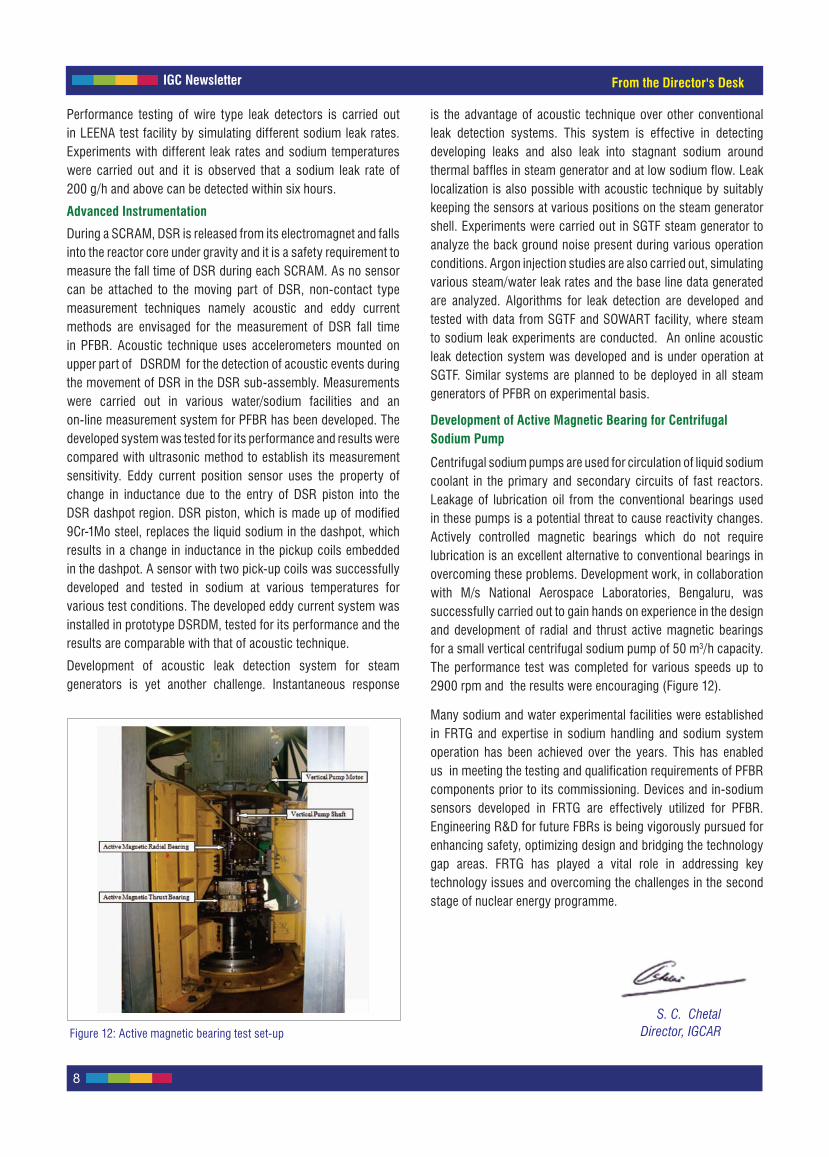
Centrifugal sodium pumps are used for circulation of liquid sodium coolant in the primary and secondary circuits of fast reactors. Leakage of lubrication oil from the conventional bearings used in these pumps is a potential threat to cause reactivity changes. Actively controlled magnetic bearings which do not require lubrication is an excellent alternative to conventional bearings in overcoming these problems. Development work, in collaboration with M/s National Aerospace Laboratories, Bengaluru, was successfully carried out to gain hands on experience in the design and development of radial and thrust active magnetic bearings for a small vertical centrifugal sodium pump of 50 m3/h capacity. The performance test was completed for various speeds up to 2900 rpm and the results were encouraging (Figure 12).
Many sodium and water experimental facilities were established in FRTG and expertise in sodium handling and sodium system operation has been achieved over the years. This has enabled us in meeting the testing and qualification requirements of PFBR components prior to its commissioning. Devices and in-sodium sensors developed in FRTG are effectively utilized for PFBR. Engineering R&D for future FBRs is being vigorously pursued for enhancing safety, optimizing design and bridging the technology gap areas. FRTG has played a vital role in addressing key technology issues and overcoming the challenges in the second stage of nuclear energy programme.
Figure 12: Active magnetic bearing test set-up
From the Director's Desk
S. C. ChetalDirector, IGCAR

IGC Newsletter
9
Exploring Distinct Amorphous States in Materials
Technical Article
There are numerous examples of structural transitions from one crystalline phase to another as a function of pressure, temperature or both. In analogy, it is likely that a glass or an amorphous solid could also undergo a structural transition from one non-crystalline state to another, i.e. may exhibit distinct amorphous phases under suitable pressure and temperature conditions. The amorphous phases could be different in terms of density, entropy, local coordination, intermediate range order, and also composition. Consequently the electronic structure and the vibrational properties are also expected to be different. It is much more challenging to distinguish between different amorphous polymorphs than in crystalline polymorphs. The early evidences of distinct amorphous states were found in ice and quartz and later in silicon. An approximately 10% change in density has been reported between low-density amorphous and high-density amorphous ice. In the case of silica the coordination number was found to be higher in the high-density amorphous phase. However, their structure and other properties have not been investigated in detail. It has also been argued that one could, in principle, expect amorphous phases corresponding to each of the crystalline polymorphs; however, few studies have been done to support this. In this context the network structures that undergo pressure-induced amorphization are of interest from the point of view of exploring the possibility of polyamorphism. The network-structures consist of corner-linked polyhedral networks and exhibit complex structural transitions driven by polyhedral tilt and rotation. This article discusses recent results of in-situ high-pressure Raman scattering and synchrotron X-ray diffraction studies carried out in two different compounds with network structures: zirconium tungstate and vanadium pentaoxide.
A number of tungstates and molybdates with open network-structure exhibit negative thermal expansion and hence are technologically important. Several of these are found to turn amorphous at high pressure and the amorphization is often irreversible. The amorphous zirconium tungstate a-Zr(WO4)2 recovered after releasing the pressure has been found to be substantially denser than the starting cubic α-phase. Based on the different densities reported and higher coordination numbers of samples recovered from high pressure it has been argued whether this could be due to distinct amorphous states similar to those reported in ice, a-silicon and fused-quartz.
The cubic phase of Zr(WO4)2 is metastable and transforms to an orthorhombic structure at 0.3 GPa before turning amorphous irreversibly at 2.1 GPa. The amorphous phase is about ~26% more dense than the cubic phase. a-Zr(WO4)2 is reported to decompose into mixture of simple oxides (ZrO2 + 2WO3), when
its temperature is raised in-situ at high pressure. On the other hand, it crystallizes back to the cubic phase if it is heated at ambient pressure. Based on the closeness of the amorphous density with that of a mixture of simple oxides, the amorphous structure has been argued to be a precursor to decomposition.
In order to investigate the evolution of the structure of the amorphous state at high pressure, powdered samples were loaded into a 160 µm hole of a preindented stainless-steel gasket of a Mao-Bell-type high-pressure diamond anvil cell. In-situ X-ray diffraction measurements were made using 0.4131 Å synchrotron radiation from NE1 beam-line at AR-Photon Factory, KEK, Tsukuba, Japan. A 30-µm collimator was used and a y-z translation stage was used for aligning the sample in the hole of the gasket with the collimator. A thin gold foil of 30 µm size was also placed within the gasket hole and the pressure was obtained from equation of state of gold. The Mao-Bell-type high-pressure diamond anvil cell was translated to bring either the sample area free from gold foil or that containing it in front of the collimator. An image plate was used as the detector. The changes in the vibrational spectrum at high pressure were also studied in a Mao-Bell-type high-pressure diamond anvil cell. The spectra were recorded using a micro-Raman set-up. The 514.5 nm line of an argon ion laser was used for exciting the sample. For Raman experiments pressure was measured using ruby fluorescence method.
Figure 1 shows the diffraction patterns at selected pressures. Four broad amorphous diffraction peaks were found up to a scattering angle of 32o. One can see that at high pressure the shoulder of the first amorphous diffraction peak (between 9 and 11o) is absent.
Figure 1: Diffraction patterns of a-Zr(WO4)2 at selected pressures

IGC Newsletter
10
All the patterns below 17 GPa exhibited this shoulder while those above 21 GPa did not. In addition, the third and fourth peaks show broadening and reduced amplitude. The diffraction patterns were analyzed quantitatively to obtain the structure factor S(Q) after correcting for Mao-Bell-type high-pressure diamond anvil cell background, θ-dependent attenuation, incoherent scattering and atomic form factors. A systematic shift of the first amorphous diffraction peak to higher 2θ was found with pressure, which resulted in a shift of the centre Q1 of the first peak in S(Q). This is shown in Figure 2a as a function of pressure. In analogy with the shift of diffraction peaks in crystalline solids at high pressure due to compression, within a given amorphous phase the position of first amorphous diffraction peak is expected to shift monotonically to higher 2θ (larger Q1). On the other hand, the data shows a change of slope around 19 GPa.
The height SMAX of the first amorphous diffraction peak of the S(Q) as a function of pressure is shown as Figure 2b. SMAX is a measure of the magnitude of the structural correlations in an amorphous phase. One can see a large discontinuous change above 19 GPa. In absence of an amorphous-amorphous (structural) transformation, the SMAX is expected to show only a constant or monotonic behaviour. Thus this discontinuity also supports occurrence of a transition. It is well known that the densities of amorphous solids and liquids scale like (Q1)
3 in analogy with the diffraction in crystalline solids. The Q1 of the samples recovered from 7 GPa is found to be smaller than that for samples recovered from 33 GPa, suggesting that the two recovered amorphous phases have different densities. The amorphous (high-density amorphous) phase appears to be about 12±1 % more dense than the low-density amorphous phase.
One can also find corresponding changes in the phonon spectra across amorphous-amorphous transition. Figure 3 shows the Raman spectra at different pressures. Because of the disorder (lack of periodicity) all the lattice and external modes disappear and only the two broad peaks corresponding to the stretching vibrations of WO4 polyhedra are found. The spectra were fitted to a sum of two Voigt functions along with a suitable background.
The symmetric stretching mode (ν1) shows a softening up to 18 GPa, above which it exhibits hardening (Figure 4). On the other hand, the asymmetric stretching mode (ν3) shows only a weak dependence on pressure. It may be pointed out that the symmetric stretching vibration of tetrahedral ions such as SO4 and WO4 depends strongly on the bond-length and the mode frequency is known to increase at high pressure due to compression of the bond. A decrease in ν1 is anomalous and would correspond to increase in the mean bond-distance. The observed softening of the ν1 mode in a-Zr(WO4)2 at high pressure suggests an increase of the mean bond length upon compression. This can occur only when oxygen atoms are displaced to facilitate a higher average oxygen coordination of tungsten. Thus the present Raman results suggest a gradual increase of coordination number within the low-density amorphous phase. The discontinuous change in ν1 mode frequency above 19 GPa supports the occurrence of an amorphous-amorphous transformation. The normal hardening behaviour of the stretching mode at still higher pressures implies that the oxygen coordination remains stable in the high-density amorphous phase.
The structure of the second system (α-V2O5) investigated consists of a layered network of corner and edge sharing VO5 square pyramids. Several high-pressure and high-temperature
Figure 3: Raman spectra of a-Zr(WO4)2 at different pressures
Figure 4: Pressure dependence of stretching mode frequencies of
tungstate ions in a-Zr(WO4)2
Figure 2: (a) Scattering vector Q1 corresponding to first amorphous diffractionpeak as a function of pressure; (b) Pressure dependence of SMAX
Technical Article

IGC Newsletter
11
studies have been carried out on V2O5 and two structural phase transitions to high pressure polymorphs have been reported. The ambient pressure α-phase has an orthorhombic structure. Above 7 GPa the high-pressure monoclinic (β) phase consists of chains of quadruple units of edge-sharing VO6 octahedra along b-axis. A transition to another monoclinic phase (δ) has also been identified above 15 GPa. Diamond-anvil cell based Raman and X-ray diffraction measurements have revealed only the α-β transition occurring around 6-7 GPa. It may also be pointed out that in V2O5, glassy and amorphous states, formed by splat-cooling (bulk) and physical vapor deposition (thin-film), respectively, are well established. However, glassy V2O5 is known to recrystallize at relatively low temperature of 185 oC.
The in-situ X-ray diffraction and Raman measurement procedures in the Mao-Bell-type high-pressure diamond anvil cell at high pressure were same as those in the first system. The sample was found to turn amorphous above 40 GPa. The diffraction pattern at 48 GPa is shown in Figure 5. This unambiguously corresponds to an amorphous state with broad peaks centered at 8.8 and 14.6o 2θ. The first peak shifts to higher 2θ as pressure is increased further due to the compression of the amorphous phase. Figure 5 also includes the diffraction pattern measured after releasing the pressure from 53 GPa. The persistence of the broad peaks in the recovered pattern suggests irreversible pressure-induced amorphization of V2O5 similar to other network structures. Thus it is of interest to examine the high-pressure amorphous phase in more detail and compare with those obtained using other methods. Unfortunately high quality diffraction patterns of glassy and vapor-deposited amorphous films with good signal to noise ratio have not been reported.
Figure 6 shows the Raman spectra in the high-pressure amorphous phase. Here only one broad peak is observed at 755 cm-1. This represents average V-O stretching vibration frequency corresponding to average V-O bond distance in the amorphous state. The mode frequency, when extrapolated to the ambient, is around 757 cm-1, which is close to the
doubly-coordinated (V-O-V) vibrations of the oxygen. This suggests that the high-pressure a-V2O5 phase has predominantly V2-O-type of bonds. Upon releasing the pressure the recovered a-V2O5 exhibits a broad Raman peak at a wave number close to that for V=O stretching vibration at ambient. This implies restoration or reformation of V=O-like bonds in the recovered amorphous state. This is understandable as a relaxation of the amorphous state upon release of pressure. It is important to compare the vibrational spectra of the samples recovered from high pressure with that reported for vapor-deposited a-V2O5. The vapor-deposited a-V2O5 exhibited prominent peaks at 520, 650, 932 and 1027 cm-1. The peaks at 520, 650 and 1027 cm-1 have been assigned to vibrations of triply-, doubly- and singly-coordinated oxygen atoms respectively, in analogy with those of the α-phase. The V=O mode frequencies in the recovered a-V2O5 (1006 cm-1) and in vapor-deposited a-V2O5 film (1027 cm-1) are close to that of V=O bond in the α-phase (995 cm-1). Thus the recovered a-V2O5 appears to have random arrangement of VO5-like structural units similar to those of a-V2O5. The difference in the vibrational frequencies in the two amorphous phases could be due to the differences in the intermediate-range order as the vibrational frequency of any given bond is strongly influenced by its immediate neighborhood.
To summarize, in-situ high pressure Raman scattering and synchrotron X-ray diffraction studies on zirconium tungstate have revealed an amorphous to amorphous transition at 19 GPa. Here the transition was identified from the discontinuities in the structural parameters such as position and height of the first peak of the structure factor and that in the tungstate internal vibrational mode frequency. In the case of V2O5, an irreversible amorphization was found to occur above 40 GPa. The differences in the structures and the Raman spectra of the high-pressure amorphous state and the sample recovered from 53 GPa suggest that the two amorphous states are distinct.
Reported by A. K. Arora, Materials Science Group
Figure 5: Diffraction patterns of pressure-amorphized V2O5 (pattern on top is that of the recovered sample at ambient pressure after subjecting it to 53 GPa)
Figure 6: Raman spectra of V2O5 at high pressure and after recovering from 53 GPa
Technical Article

IGC Newsletter
12
Launching of e-Tendering in Civil Engineering Group
The mandate of Civil Engineering Group is to design and establish the additional infrastructure required for the R&D programmes of our Centre. Towards accomplishing its goal, the Civil Engineering Group is concerned with development of land, civil construction, structural and mechanical fabrication, water supply, sanitary, road works, horticulture and other facilities. This Group is also involved in the maintenance and repairs of buildings. This Group conceptually plans its works, designs it as per relevant codes and executes them as per the works procedure.
Generally the works are executed by tendering, a process by which bids are invited from interested contractors to carry out specific packages of work. The invitations for public tenders are given wide publicity through websites, as well as through newspapers. The tender documents are then sold to eligible contractors, in person and also uploaded in the website. Tenderers can download the same and submit the completed tender through courier or speed post within the stipulated time. The received and accepted tenders are then evaluated to ascertain the lowest evaluated bid interms of technical and financial aspects of the scope for the complete work covered under the document. The tendering process is done with the aim of promoting utmost transparency and also to encourage participation of a wide spectrum of competitors. The tendering process is usually expensive and requires lengthy timeframe.
In order to make the tendering process both time and cost effective, it was proposed to start the e-tendering of CEG works including e-quoting, as per guidelines from central vigilance commission and directions from management.
e-Tendering means carrying out all traditional tendering activities from the advertising of the requirement through to the placing of the contract in an electronic form, using the internet. The main objective for e-tendering is to bring security, authenticity and accountability into the tendering process. e-Tendering offers comparative and qualitative comparisons amongst bidders to facilitate an accurate evaluation process.
The many advantages of the e-tendering process include: faster turnaround time, greater transparency, economic and eco-friendly, access to information all through the day, ease and speed with which changes or clarifications to the tender documents can be notified, ability of bidder to modify or withdraw their bids any time prior to the closure of the tender, automatic rejection of incomplete bids, thereby giving bidders the opportunity to correct them, arguably expands the market by allowing smaller companies greater access, regardless of location, to respond in a cost-effective way without the traditional concern of how to get the bid on time and arguably expands the market to a greater number of bidders and to bidders to a greater number of projects.
For all the constituent units of DAE, the prime nodal agency that provides technical support for works is M/s. ITI Limited, who are also the technical support provider for Central Public Works Department (CPWD). Hence, a tie up with M/s. ITI Limited was made as a part of the e-tendering process. A training programme was then organized for the tenderers to get familiarized with the procedures in order to minimize user related problems in tender submission. To authenticate the identity of vendors as well as buyers and to ensure secure data transacted online, Digital Signature Certificates (DSC) were procured and provided to various user groups associated with tendering activities.
A user friendly web portal named Tenderwizard (Figure 1) has been created for the purpose. After formalizing all the preliminary requirements, the e-tendering with e-quoting was launched on June 25, 2012 for all works costing above Rs. 1 crore. As a part of this initiative, the first tender document was officially uploaded by Chief Engineer (Civil)/Associate Director, CEG on July 9, 2012 in the web portal www.tenderwizard.com/DAE.
The Tender wizard web portal is very simple and convenient to use and offers the tenderer offline quoting at any convenient time.
Reported by C. Sivathanu Pillai Civil Engineering GroupFigure 1: A screen shot of Tender wizard Portal
Technical Article
IGC Newsletter
13
Young Officer's Forum
Young Officer’s FORUM
Design and Development of Soft-Core Processor Based Remote Terminal Units for Fast Breeder Reactors
Shri Aditya Gour received his B.E degree (Electronics & Communication Engineering) in 2007 from Rajiv Gandhi Technical University, Bhopal and the M.Tech Degree in Nuclear Engineering & Sciences in 2010 from Homi
Bhabha National Institute. He is from the 2nd batch of BARC Training school at IGCAR campus and currently working as a Scientific Officer in Real Time Systems Division, ICG, EIRSG. His current area of interest is in the field of FPGA based embedded systems design for nuclear reactors.
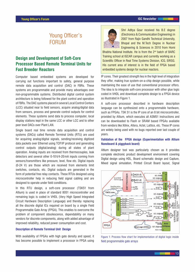
Figure 1: Process flow chart for implementation of digital logic inside
field programmable gate arrays
Computer based embedded systems are developed for carrying out functions important to safety, general purpose remote data acquisition and control (DAC) in FBRs. These systems are programmable and provide many advantages over non-programmable systems. Distributed digital control system architecture is being followed for the plant control and operation of FBRs. The DAC systems placed in several Local Control Centers (LCC) situated near to field sensors, acquire analog/digital data from sensors, process and generate control outputs for control elements. These systems send data to process computer, local display stations kept in the same LCC or other LCC and to other peer level DACs over Plant LAN.
Single board real time remote data acquisition and control systems (DACs) called Remote Terminal Units (RTU) are used for acquiring analog/digital signals, sending/receiving digitized data packets over Ethernet using TCP/IP protocol and generating control outputs (digital/analog) during all states of plant operation. Analog inputs are received from thermocouples, leak detectors and several other 0-10 V/4-20 mA inputs coming from sensors/transmitters like pressure, level, flow etc. Digital inputs (0-24 V) are those which are received from elements limit switches, contacts, etc. Digital outputs are generated in the form of potential free relay contacts. These RTUs designed using microcontroller help in reducing field signal cabling and are designed to operate under field conditions.
In this RTU design, a soft-core processor (TSK51 from Altium) is used in place of standard 8051 microcontroller and remaining logic is coded in VHDL (Very High Speed Integrated Circuit Hardware Description Language) and thereby replacing all the discrete digital ICs required on board by a single Field Programmable Gate Array (FPGA). This enables to overcome the problem of component obsolescence, dependability on many vendors for discrete components, along with added advantage of improved reliability, reduced power consumption and cost.
Description of Remote Terminal Unit Design
With availability of FPGAs with high gate density and speed, it has become possible to implement a processor in FPGA using
IP cores. Their greatest strength lies in the high level of integration they offer, making true system-on-a-chip design possible, while maintaining the ease of use that conventional processor offers. The idea is to integrate soft-core processor with other glue logic coded in VHDL and download complete design to a FPGA device as illustrated in Figure 1.
A soft-core processor described in hardware description language can be synthesized onto a programmable hardware, such as FPGAs. TSK 51 is the IP core of an 8 bit microcontroller, provided by Altium, which executes all ASM51 instructions and can be downloaded to Flash or SRAM based FPGAs available from vendors like Xilinx, Altera, Actel, Lattice, etc. These IP cores are widely being used with no bugs reported over last couple of years.
Validation of the FPGA design (Experimentation with Altium Nanoboard & piggyback board)
Altium designer tool was particularly chosen as it provides complete electronic product development environment covering Digital design using HDL, Board schematic design and Capture, Mixed signal simulation, Printed Circuit Board layout, Signal
IGC Newsletter
14
Young Officer's Forum
Figure 2: Set-up for validation of the field programmable gate arrays
design using development board
Figure 3: Flow chart for component interconnections with FPGA in
schematics design for 16-Ch DI & 16-Ch RO RTU board
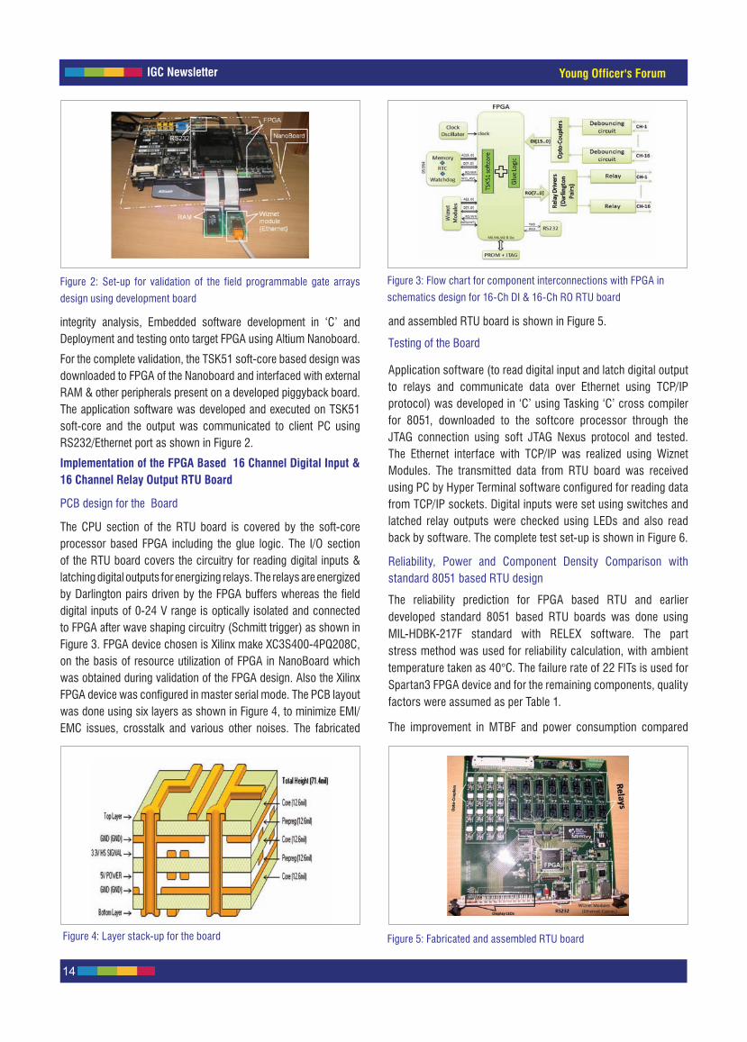
integrity analysis, Embedded software development in ‘C’ and Deployment and testing onto target FPGA using Altium Nanoboard.
For the complete validation, the TSK51 soft-core based design was downloaded to FPGA of the Nanoboard and interfaced with external RAM & other peripherals present on a developed piggyback board. The application software was developed and executed on TSK51 soft-core and the output was communicated to client PC using RS232/Ethernet port as shown in Figure 2.
Implementation of the FPGA Based 16 Channel Digital Input & 16 Channel Relay Output RTU Board
PCB design for the Board
The CPU section of the RTU board is covered by the soft-core processor based FPGA including the glue logic. The I/O section of the RTU board covers the circuitry for reading digital inputs & latching digital outputs for energizing relays. The relays are energized by Darlington pairs driven by the FPGA buffers whereas the field digital inputs of 0-24 V range is optically isolated and connected to FPGA after wave shaping circuitry (Schmitt trigger) as shown in Figure 3. FPGA device chosen is Xilinx make XC3S400-4PQ208C, on the basis of resource utilization of FPGA in NanoBoard which was obtained during validation of the FPGA design. Also the Xilinx FPGA device was configured in master serial mode. The PCB layout was done using six layers as shown in Figure 4, to minimize EMI/EMC issues, crosstalk and various other noises. The fabricated
and assembled RTU board is shown in Figure 5.
Testing of the Board
Application software (to read digital input and latch digital output to relays and communicate data over Ethernet using TCP/IP protocol) was developed in ‘C’ using Tasking ‘C’ cross compiler for 8051, downloaded to the softcore processor through the JTAG connection using soft JTAG Nexus protocol and tested. The Ethernet interface with TCP/IP was realized using Wiznet Modules. The transmitted data from RTU board was received using PC by Hyper Terminal software configured for reading data from TCP/IP sockets. Digital inputs were set using switches and latched relay outputs were checked using LEDs and also read back by software. The complete test set-up is shown in Figure 6.
Reliability, Power and Component Density Comparison with standard 8051 based RTU design
The reliability prediction for FPGA based RTU and earlier developed standard 8051 based RTU boards was done using MIL-HDBK-217F standard with RELEX software. The part stress method was used for reliability calculation, with ambient temperature taken as 40°C. The failure rate of 22 FITs is used for Spartan3 FPGA device and for the remaining components, quality factors were assumed as per Table 1.
The improvement in MTBF and power consumption compared
Figure 4: Layer stack-up for the board Figure 5: Fabricated and assembled RTU board

IGC Newsletter
15
Young Officer's Forum
with earlier design is as given in Table 2 and Table 3 respectively.
The FPGA based RTU board and the earlier developed 8051 based RTU board is shown in Figure 7. The circuitry for FPGA based RTU board needs less space and interconnections when compared with the earlier one.
Figure 6: Complete set-up for RTU testing Figure 7: Component density comparison for the RTU board
RTU based on
FPGA 89C51
FPGA Based RTU failures/million hours
2.049141 3.064774
MTBF, Predicted 488009.33 hours 326288.4 hours
Reliability, Predicted 0.999795 0.999694
Table 2: Reliability prediction for the RTU boards
ValueRTU based on
FPGA 89C51
Current drawn by board 500 mA 650 mA
Power supply 5 V 5 V
Power consumption 2.5 W 3.25 W
Table 3: Power calculations
Table 1: Quality factor for components
Component QF Component QF
Microcircuits 5 Capacitors P
Semiconductors JAN Relays MIL SPEC
Resistors P Connectors MIL SPEC
The development of soft-core processor based remote terminal units was completed, where an IP core processor was chosen in place of standard microcontroller and the remaining glue logic
was coded in VHDL. Several tests were conducted with hardware development platform using NanoBoard and based on that a standard RTU board was developed and tested successfully. The analysis for reliability prediction, power calculation and component density were also done, confirming the achievements of the desired goal.
In future, it is planned to deploy this concept for various application specific embedded systems. For analog portions like filters, analog multiplexers, ADC, instrumentation amplifier and Op-amps, the concept of Field Programmable Analog Array (FPAA) is being deployed which will reduce the analog ICs in the design. Wiznet module (for TCP/IP communication) was used in the existing designs, which is becoming obsolete and its limitation of only four sockets makes us plan for its replacement with softcore EMAC controllers also downloaded to FPGA and a software TCP/IP stack implemented over an operating system ported to run on the softcore processor. Micrium provides such open source operating system and TCP/IP stacks for real time embedded applications. Experiments have been done successfully on a Xilinx SP605 development board and the design of universal RTU with RTOS has been done and fabrication is under progress.
Since this RTU boards are not envisaged to be used in radiation environment, radiation effects were not taken into consideration. But for use of RTU in radioactive environment, radiation tolerant ICs are to be used. Though Spartan3 family FPGA used in present RTU design is not radiation tolerant, this design can be easily ported to radiation tolerant Spartan6 or Vertex family. Also, many design techniques like Triple Module redundancy for logic, data redundancy, latch-up protection, configuration memory read back etc. can be used for handling single event effects or bit flips .
Reported by Aditya Gour, Instrumentation and Control Group, Electronics, Instrumentation and Radiological Safety Group
IGC Newsletter
16
Young Researcher's Forum
Applications of Ionic Liquids at the Back End of Nuclear Fuel Cycle
Young Researcher’s FORUM
Shri Alok Rout obtained his M.Sc. (Organic Chemistry) from Utkal University, Bhubaneswar. He joined IGCAR as a Junior Research Fellow in March 2007 and pursued his Ph.D, under the guidance of Dr. T. G. Srinivasan, Raja Ramanna Fellow,
Chemistry Group. He submitted his dissertation titled “Room Temperature Ionic Liquids for the Separation of Actinides and Fission Products” to HBNI in April 2012. He has authored thirteen peer reviewed journal papers and nine conference proceedings. He has attended the international conference “ILSEPT 2011” held at Sitges, Spain, where he delivered a key note lecture and chaired a session.
Room temperature ionic liquids (RTILs) are receiving increased
attention for possible applications in the area of nuclear fuel
reprocessing and waste management. Room temperature ionic
liquids are compounds composed fully of dissociated ions and
melt at temperatures lower than 373 K. The room temperature
ionic liquids have many attractive properties for nuclear fuel cycle
applications. Consequently, there has been a significant increase in
the studies related to the use of room temperature ionic liquids in
aqueous and non-aqueous reprocessing applications. Essentially,
room temperature ionic liquids are investigated as a possible
substitute to the molecular diluent in solvent extraction procedures.
Some of the striking features of RTILs that make them promising for
nuclear fuel cycle application are (i) manipulation of the selectivity
of target metal ion by changing the cation-anion combination
rather than redesigning the structure of extractant, (ii) minimal fire
hazard due to near-zero vapour pressure of room temperature ionic
liquids (iii) tunability to incinerable form, which would simplify the
management of spent organic waste and (iv) functionalisation with
organic moieties for target specific applications. In view of these
advantages, some studies were carried out in our laboratory aimed
at the separation of actinides and fission products using ionic liquid
as solvent medium.
Room Temperature Ionic Liquids as Diluent
Third Phase Formation behavior in Room Temperature Ionic Liquids
Third phase formation is a phenomenon which needs to be
adhered in solvent extraction. This term “third phase formation”
refers to the splitting of organic phase, into two phases with the
heavier one, rich in metal–solvate, and the lighter phase rich in
diluent. This occurs due to the poor compatibility of polar metal-
solvate with a non-polar diluent phase at metal loadings beyond
a particular loading in organic phase referred as limiting organic
concentration. The corresponding aqueous phase concentration of
metal ion is called as critical aqueous concentration. Formation
of the third phase is a serious concern in solvent extraction
process as it could cause complications during continuous
Figure 1: Illustration for third phase formation using room temperature ionic liquids
Figure 2: Variation of Eu(III) loading in 0.2 M CMPO - 1.2 M TBP- C4mimNTf2 at various initial concentrations

IGC Newsletter
17
Young Researcher's Forum
counter-current extraction stages. In order to overcome this, the
third phase formation behavior of Eu(III) in a solution of TRUEX
extractant (0.2 M CMPO – 1.2 M TBP) in the ionic liquid, 1-butyl-3-
methylimidazolium bis(trifluoromethanesulfoni)imide (C4mimNTf2)
was studied. The illustration is shown in Figure 1.
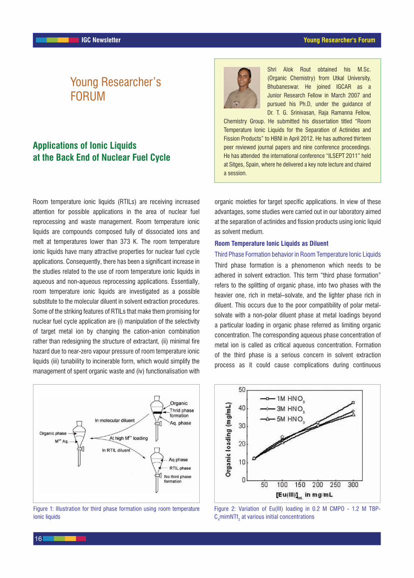
Figure 2 shows the variation in the loading of Eu(III) in 0.2 M
CMPO-1.2 M TBP/C4mimNTf2 as a function of initial concentration
of Eu(III) aqueous phase ranging from 20 to 300 mg/mL. It is
observed that loading of Eu(III) in ionic liquid phase increases from
~12 to 40 mg/mL with the increase in concentration of Eu(III)
from 20 to 300 mg/mL in aqueous phase. Interestingly in all cases,
third phase formation was not observed, which was in striking
contrast to the 0.2 M CMPO – 1.2 M TBP-n-DD system, where the
limiting organic concentration was only 9 mg/mL (as illustrated in
Figure 1). The absence of third phase in ionic liquid system could
be attributed to the polar nature of the ionic liquid, C4mimNTf2 and
its ability to dissolve/stabilize the Eu(III)– CMPO solvate. However,
a “crud –type” precipitate was observed in the absence of TBP and
it was dissolved by adding TBP to the extent of 0.2 M. This study
also indicated that the stoichiometry of metal-solvate in organic
phase varied from 1:3 (Eu: CMPO) at trace levels to 1:1 at higher
europium loadings.
Lanthanide – Actinide separation in Room Temperature Ionic
Liquids
The most challenging task at the back end of the nuclear fuel
cycle is the lanthanide – actinide separation. This is due to the
similarity in the physical and chemical properties of lanthanides
and actinides present in high-level liquid waste. However, there are
some marginal differences with respect to the chemical reactivity
towards certain reagents and such differences have been exploited
for the lanthanides/actinides separation. In this context, we have
carried out lanthanides-actinides separation in room temperature
ionic liquid medium, using Eu(III) and Am(III) as representative of
lanthanide and actinide. Mutual separation of Eu(III) from Am(III) was
carried out in the ionic liquid diluent, 1-octyl-3-methylimidazolium
bis(trifluoromethanesulfonyl)imide (C8mimNTf2). The extractants
used were bis(2-ethylhexyl)phosphoric acid (D2EHPA) and
bis(2-ethylhexyl)diglycolamic acid (HDEHDGA). Separation of
Eu(III) from Am(III) using ionic liquid medium is illustrated in
Figure 3. Our studies confirmed that these extractants in
conjunction with ionic liquid provide excellent extraction of
Am(III) and Eu(III) from aqueous solutions of widely differing
compositions. The differential complexing ability of the extractant
in ionic liquid phase and diethylenetriaminepentaaceticacid (DTPA)
in aqueous phase was exploited to optimize the conditions needed
for efficient separation of trivalent lanthanides from actinides. The
stoichiometry of metal – solvate was found to be 1: 3. HDEHDGA
was found to be superior to D2EHPA for efficient separation. At
pH 3 and using 0.005 M DTPA, D2EHPA gave a separation factor of
~35; however, HDEHDGA required only 10-4 M DTPA for achieving
a separation factor of ~150.
Room Temperature Ionic Liquids as Extractant
Functionalized Ionic Liquids
The cationic or anionic part of the room temperature ionic liquid
tethered covalently with organic functionalities, which can
perform target specific applications are known as functionalized
ionic liquids or task specific ionic liquids. Owing to the presence
of functional group, the resultant functionalized ionic liquid
is expected to show the properties of both ionic liquid and
organic functionality. We synthesized functionalized ionic
liquids (Figure 4), namely, diethyl-2-(3-methylimidazolium)ethyl
phosphonatebis(trifluoromethanesulfonyl)imide (ImPNTf2) and
N,N–dioctyl-2-(3-methylimidazolium) bis(trifluoromethanesulfonyl)
imide (DOAImNTf2) and evaluated their efficiency in the extraction
of actinides and fission products from nitric acid medium. The
extraction of U(VI), Am(III) and fission products in these was
Figure 3: Illustration of Lanthanide – Actinide separation using RTILs as medium
DTPA = Diethylenetriaminepentaacetic acid,HDEHDGA = bis(2-ethylhexyl)diglycolamic acid, D2EHPA = bis(2- ethylhexyl)phosphoric acid
Figure 4: Structure of some of the ionic liquids that were studied
1-alkyl-3-methylimidazolium bis(trifluoromethanesulfonyl)imides (C-mimNTf2 )

IGC Newsletter
18
Young Researcher's Forum
Table 1: Separation factors of Pu(IV) from U(VI) and Am(III) at various nitric acid concentrations obtained using ionic liquids at 298 K
Figure 6: Variation in the distribution ratios of Eu(III) as a function ofpHini with different organic phase in n-DD. Aqueous phase: HNO3. O/A =1
insignificant. However, efficient extraction of Pu(IV) was achieved
using the ionic liquid-extractants ImPNTf2 and DOAImNTf2 present
in the ionic liquid diluents (CnmimNTf2; n = 4, 6 and 8). Above
4 M nitric acid, the primary mode of plutonium(IV) transfer in
ionic liquid phase was observed to be anion exchange. Below
4 M, the investigation indicated the possibility of metal solvate
complex (Pu(IV)–(DOAImNTf2)3) or (Pu(IV)–(ImPNTf2)3) formation
in ionic liquid phase. Unlike the traditional systems, the ionic liquid
extractant, ImPNTf2 (or DOAImNTf2), is selective only towards
plutonium (IV) over other actinides and fission products. In addition,
the task specific property was observed only upon functionalization
of the phosphonate or amide moiety on to the imidazolium cation.
Table 1 shows the separation factors achieved with the use of RTILs.
Extraordinary separation factors of 20–250 for plutonium (IV)
over uranium (VI) and 103 –105 for plutonium (IV) over
americium (III) were achieved by using ImPNTf2/CnmimNTf2
(n = 4 and 8) depending on the concentration of nitric acid. Similarly,
the separation factor of Pu(IV) over U(VI) was found to vary from
40 to 3400 in DOAImNTf2 solution depending upon the concentration
of nitric acid employed for extraction.
Room Temperature Ionic Liquids with Strongly Coordinating Anions
Ionic liquids with strongly coordinating anions are becoming
popular in addition to the functionalized ionic liquids. The
advantages of such ionic liquids over functionalized ionic liquids
are simple method of preparation, low viscosity despite having
metal-complexing functionalities, higher loading of metals,
unusual miscibility with non-polar diluents such as n-dodecane
(n-DD) etc. We synthesized two novel aliquat-based ionic liquids
containing phosphate anion, [A336]+[P204]- and diglycolamate
anion, [A336]+[DGA]- ; the structure of which are shown in
Figure 5. Interestingly, these ionic liquids are soluble in the
paraffinic diluents such as n-DD and its higher homologues. The
extraction behavior of Eu(III) in a solution of these ionic liquids
present in different molecular diluents was studied as a function of
various parameters. The data obtained were compared with those
obtained in a solution comprising the precursors of the ionic liquid.
Figure 6 shows the comparision of the distribution ratio of Eu(III)
in both the systems equilibrated for one hour at 298 K. It is
observed that the distribution ratio of Eu(III) was remarkably higher
in comparison to that of its precursors. The extraction of Eu(III)
in [A336]+[P204]- and [A336]+[DGA]- ionic liquids showed a
strong dependence on the nature of molecular diluent used. The
distribution ratio of Eu(III) increased with increase of pH; at pH > 2,
the distribution ratio obtained in ionic liquids was much higher than
their precursors. Our studies revealed that it is possible to separate
Eu(III) from Am(III) by adding DTPA to the aqueous phase. These
ionic liquids can extract the trivalents as neutral metal (III) nitrate
complexes.
Reported by Alok Rout, Chemistry Group
SolventSeparation factor of Pu(IV) from
U(VI) Am(III)
1 M 2 M 3 M 4 M 5 M 1 M 5 M
0.4 M ImPNTf2/ C4mimNTf2 521 175 117 55 33 3 x 10⁵ 8.6 x 10³
0.4 M ImPNTf2/C6mimNTf2 0.15 0.09 0.16 30 4.2 5 200
0.4 M ImPNTf2/C8mimNTf2 84 78.8 32 22.6 28 4 x 10³ 2.1 x 10³
0.3 M DOAImNTf2/C4mimNTf2 2200 -- 230 105 41 1466 4000 Figure 5: Structure of aliquat-based ionic liquids

IGC Newsletter
19
New's and Events
Twenty five students from BITS Pilani (Pilani, Hyderabad and Goa campuses) underwent BITS Practice School-I for six weeks at our Centre. Dr. P. R. Vasudeva Rao, Director, Chemistry Group inaugurated the Practice School at IGCAR on May 21, 2012. The BITS Practice School bridges the professional world with the educational world. The course aims at exposing the students to industrial and research environments, on how the organizations work, to follow and maintain work ethics, study the core subjects and their application in the organization, participate in some of the assignments given to them in the form of projects. The students were from various Engineering disciplines
namely, Civil, Chemical, Computer Science, Electronics & Instrumentation, Electronics & Communication and Electrical & Electronics. Students carried out challenging projects in various Groups of the Centre in line with their discipline. During the period of their stay, they visited various facilities at IGCAR, BHAVINI and MAPS. Quiz, project work presentations, group discussions and report writing formed the practice school curriculum. Shri S. C. Chetal, Director, IGCAR had an interaction session with the students. The valedictory function was held on July 13, 2012 Shri S. A. V. Satya Murty, Director, Electronics, Instrumentation and Radiological Safety Group delivered the valedictory address and distributed the certificates to the students.
Shri S. C. Chetal, Director, IGCAR interacting with the students from BITS Practice School
BITS Practice SchoolMay 21- July 13, 2012
Reported by M. Sai Baba, Coordinator-BITS Practice School
News and Events
Students from BITS Practice School with senior colleagues of the Centre
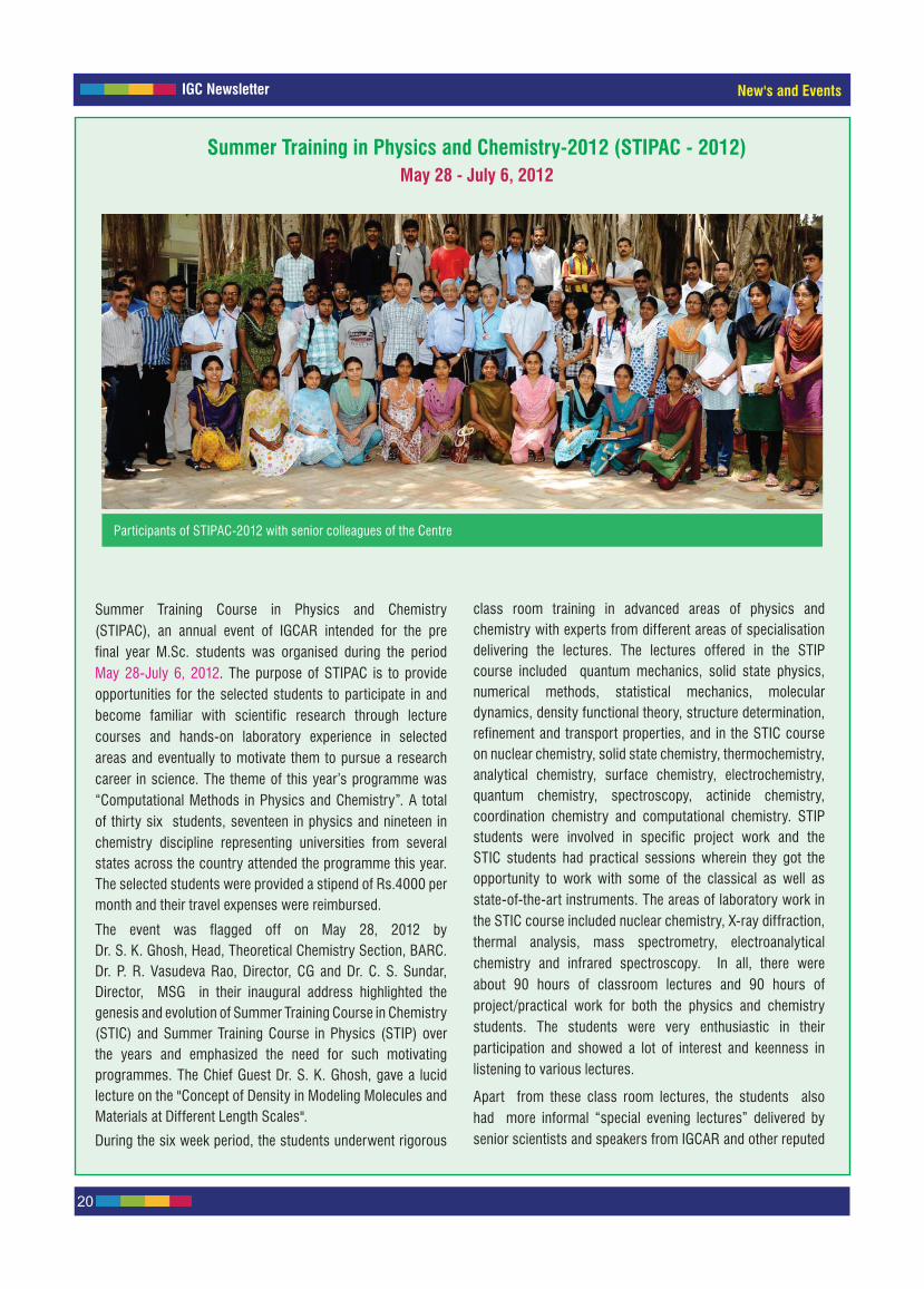
IGC Newsletter
20
New's and Events
Participants of STIPAC-2012 with senior colleagues of the Centre
Summer Training Course in Physics and Chemistry (STIPAC), an annual event of IGCAR intended for the pre final year M.Sc. students was organised during the period May 28-July 6, 2012. The purpose of STIPAC is to provide opportunities for the selected students to participate in and become familiar with scientific research through lecture courses and hands-on laboratory experience in selected areas and eventually to motivate them to pursue a research career in science. The theme of this year’s programme was “Computational Methods in Physics and Chemistry”. A total of thirty six students, seventeen in physics and nineteen in chemistry discipline representing universities from several states across the country attended the programme this year. The selected students were provided a stipend of Rs.4000 per month and their travel expenses were reimbursed.
The event was flagged off on May 28, 2012 by Dr. S. K. Ghosh, Head, Theoretical Chemistry Section, BARC. Dr. P. R. Vasudeva Rao, Director, CG and Dr. C. S. Sundar, Director, MSG in their inaugural address highlighted the genesis and evolution of Summer Training Course in Chemistry (STIC) and Summer Training Course in Physics (STIP) over the years and emphasized the need for such motivating programmes. The Chief Guest Dr. S. K. Ghosh, gave a lucid lecture on the "Concept of Density in Modeling Molecules and Materials at Different Length Scales".
During the six week period, the students underwent rigorous
class room training in advanced areas of physics and chemistry with experts from different areas of specialisation delivering the lectures. The lectures offered in the STIP course included quantum mechanics, solid state physics, numerical methods, statistical mechanics, molecular dynamics, density functional theory, structure determination, refinement and transport properties, and in the STIC course on nuclear chemistry, solid state chemistry, thermochemistry, analytical chemistry, surface chemistry, electrochemistry, quantum chemistry, spectroscopy, actinide chemistry, coordination chemistry and computational chemistry. STIP students were involved in specific project work and the STIC students had practical sessions wherein they got the opportunity to work with some of the classical as well as state-of-the-art instruments. The areas of laboratory work in the STIC course included nuclear chemistry, X-ray diffraction, thermal analysis, mass spectrometry, electroanalytical chemistry and infrared spectroscopy. In all, there were about 90 hours of classroom lectures and 90 hours of project/practical work for both the physics and chemistry students. The students were very enthusiastic in their participation and showed a lot of interest and keenness in listening to various lectures.
Apart from these class room lectures, the students also had more informal “special evening lectures” delivered by senior scientists and speakers from IGCAR and other reputed
Summer Training in Physics and Chemistry-2012 (STIPAC - 2012)May 28 - July 6, 2012

IGC Newsletter
21
New's and Events
Graduation Function of the Sixth Batch of Trainee Scientific Officers of BARC Training School at IGCAR
July 31, 2012
Sixth Batch of Graduates of BARC Training School at IGCAR with Dr. R. K. Sinha, Chairman, AEC and Secretary, DAE, Prof. Bhaskar Ramamurthi, Director, IITM, Chennai, Dr. Prabhat Kumar, Chairman and Managing Director, BHAVINI, Shri S. C. Chetal, Director, IGCAR and senior colleagues of the Centre
The sixth batch of thirty five Trainee Scientific Officers from the BARC Training School at IGCAR have successfully completed their training and were graduated in a special ceremony that took place on July 31, 2012 in the Sarabhai Auditorium, Homi Bhabha Building, IGCAR.
Prof. Bhaskar Ramamurthi, Director, Indian Institute of Technology Madras, Chennai was the Chief Guest. Dr. R. K. Sinha, Chairman, AEC and Secretary, DAE presided over the function. Dr. M. Sai Baba, Associate Director, RMG welcomed the gathering. Shri S. C. Chetal,
Dr. R. K. Sinha, Chairman, AEC and Secretary, DAE, Prof. Bhaskar Ramamurthi, Director, IITM, Chennai, Shri S.C.Chetal, Director, IGCAR, Dr. M. Sai Baba, Associate Director, RMG, Shri R. V. Subba Rao, Head, OCES-TS, RMG during the release of souvenir at the graduation function
institutes: Prof. E. Prasad, IIT Madras (Light Interaction with Matter); Dr. T. G. Srinivasan, Raja Ramanna Fellow, IGCAR (Advantages of Nuclear Energy); Prof R. Asokamani (Electronic Structure); Prof. Srinivas Hotha, IISER, Pune, (Development of Chemistry over the Last Century and Advantages of Becoming a Researcher); Shri T. N. Vaidyanathan, MAPS (Energy Scenario and Role of Nuclear Power); Dr. Prabhat Kumar, Chairman and Managing Director, BHAVINI (Managing Mega Projects), Dr. C. S. Sundar, Director, MSG (Superconductivity at 100); Prof. Anil Kumar, IIT Bombay (Magic and Science: The Art of "ACTIVE" Learning and Research); Dr. P. R. Vasudeva Rao, Director, CG (Science and Excitement); Dr. M. Sai Baba,
AD, RMG (Improving Performance by Self Motivation) and Dr. Pankaj Mehta, IGCAR (Power of the Subconscious Mind).
The students also had the opportunity to visit various facilities at Kalpakkam such as FBTR, BHAVINI, MAPS and the UGC-DAE-CSR node. The concluding function was held on July 6, 2012. Prof. R. Murugavel, Head, Department of Chemistry, Indian Institute of Technology Bombay delivered the valedictory address and also distributed the certificates to the students. He also delivered a technical lecture on "Recent Developments on Porous Solids".
Reported by Lakshmi Narasimhan, Course Director, STIPAC-2012
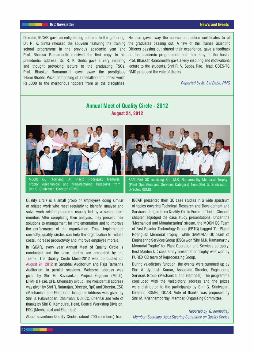
IGC Newsletter
22
New's and Events
Quality circle is a small group of employees doing similar or related work who meet regularly to identify, analyze and solve work related problems usually led by a senior team member. After completing their analysis, they present their solutions to management for implementation and to improve the performance of the organization. Thus, implemented correctly, quality circles can help the organization to reduce costs, increase productivity and improve employee morale.
In IGCAR, every year Annual Meet of Quality Circle is conducted and the case studies are presented by the Teams. The Quality Circle Meet–2012 was conducted on August 24, 2012 at Sarabhai Auditorium and Raja Ramanna Auditorium in parallel sessions. Welcome address was given by Shri G. Ravisankar, Project Engineer (Mech), DFMF & Head, CFD, Chemistry Group. The Presidential address was given by Shri R. Natarajan, Director, RpG and Director, ESG (Mechanical and Electrical). Inaugural Address was given by Shri B. Palaniappan, Chairman, QCFICC, Chennai and vote of thanks by Shri G. Kempulraj, Head, Central Workshop Division, ESG (Mechanical and Electrical).
About seventeen Quality Circles (about 200 members) from
Annual Meet of Quality Circle - 2012August 24, 2012
IGCAR presented their QC case studies in a wide spectrum of topics covering Technical, Research and Development and Services. Judges from Quality Circle Forum of India, Chennai chapter, adjudged the case study presentations. Under the ‘Mechanical and Manufacturing’ stream, the MOON QC Team of Fast Reactor Technology Group (FRTG) bagged ‘Dr. Placid Rodriguez Memorial Trophy’, while SAMURAI QC team of Engineering Services Group (ESG) won ‘Shri M.K. Ramamurthy Memorial Trophy’ for Plant Operation and Services category. Best Maiden QC case study presentation trophy was won by PUREX QC team of Reprocessing Group.
During valedictory function, the events were summed up by Shri A. Jyothish Kumar, Associate Director, Engineering Services Group (Mechanical and Electrical). The programme concluded with the valedictory address and the prizes were distributed to the participants by Shri G. Srinivasan, Director, ROMG, IGCAR. Vote of thanks was proposed by Shri M. Krishnamoorthy, Member, Organising Committee.
Reported by G. Kempulraj, Member Secretary, Apex Steering Committee on Quality Circles
MOON QC receiving Dr. Placid Rodriguez Memorial Trophy (Mechanical and Manufacturing Category) from Shri G. Srinivasan, Director, ROMG
SAMURAI QC receiving Shri M.K. Ramamurthy Memorial Trophy (Plant Operation and Services Category) from Shri G. Srinivasan, Director, ROMG
Director, IGCAR gave an enlightening address to the gathering. Dr. R. K. Sinha released the souvenir featuring the training school programme in the previous academic year and Prof. Bhaskar Ramamurthi received the first copy. In his presidential address, Dr. R. K. Sinha gave a very inspiring and thought provoking lecture to the graduating TSOs. Prof. Bhaskar Ramamurthi gave away the prestigious ‘Homi Bhabha Prize’ comprising of a medallion and books worth Rs.5000 to the meritorious toppers from all the disciplines.
He also gave away the course completion certificates to all the graduates passing out. A few of the Trainee Scientific Officers passing out shared their experience, gave a feedback on the academic programmes and their stay at the hostel. Prof. Bhaskar Ramamurthi gave a very inspiring and motivational lecture to the students. Shri R. V. Subba Rao, Head, OCES-TS, RMG proposed the vote of thanks.
Reported by M. Sai Baba, RMG

IGC Newsletter
23
Visit of Dignitaries
IGC Colloquium on "Lessons from Fukushima" was delivered by Shri S. K. Chande, Vice-Chairman, Atomic Energy Regulatory Board
Prof. Bala Balachandran, Founder and Dean and Prof. S. Sriram, Executive Director from Great Lakes Institute of Management, Chennai with Shri S. C. Chetal, Director, IGCAR
Shri S. K. Chande, Vice-Chairman, Atomic Energy Regulatory Board during his visit to the Centre on July 18, 2012 delivered the IGC Colloquium on "Lessons from Fukushima".
Prof. Bala Balachandran, Founder and Dean and Prof. S. Sriram, Executive Director, Great Lakes Institute of Management, Chennai visited the Centre on September 12, 2012. Prof. Bala Balachandran and Prof. S. Sriram met Shri S. C. Chetal, Director, IGCAR and discussed on neighborhood development programmes and related issues.
Structure and Thermodynamics of Emerging Materials (STEM-2012) Theme meeting on Challenges and Issues in Surface Modification, Thin Films and Coatings
November 5-6, 2012A theme meeting on Structure and Thermodynamics of Emerging Materials (STEM-2012) focusing on the specific topic of
“Challenges and Issues in Surface Modification, Thin Films and Coatings” will be organized in Convention Centre, Anupuram during
November 5-6, 2012. STEM 2012 is being organized jointly by IGCAR and Kalpakkam Chapter of the Indian Institute of Metals. The
theme meeting is sponsored by Board of Research in Nuclear Sciences, India. During STEM 2012, a series of invited lectures will
be organized to cover various topics like fundamental aspects of surface engineering, surface modification by laser and plasma
based processes, microstructural and surface characterization of thin films and multi layers and evaluation of surface properties.
The invited speakers are drawn from international and national institutes like, HZB, Berlin (Germany), NIMS (Japan), BARC,
UGC-DAE-CSR, RRCAT, IITM, Anna University, IPR, DMRL, NAL etc. The theme meeting seeks to provide a forum for the participants
to enhance their knowledge with respect to recent developments and design concepts in surface engineering and also interact with
renowned experts in this field.
Forthcoming Meeting / Conference
Address for CorrespondenceShri E. MohandasConvener, STEM -2012 Head, Materials Synthesis & Structural Characterization Division, Physical Metallurgy Group Metallurgy and Materials Group, IGCAR, Kalpakkam–603102Tel: +91-44-27480500 Extn-22418; Fax: +91-44-27480202E-mail: [email protected]
Visit of Dignitaries and Forthcoming Events

IGC Newsletter
24
A conference on "Recent Trends in Computer and Networking Technologies (Sangoshthi-2012)" will be organized at IGCAR during December 21-23, 2012. The Conference is being organized by Library and Information Science Promotion Society [LISPS] in association with IGCAR, BHAVINI, BARC-F and MAPS.
The 24th annual general meeting of the MRSI (MRSI-AGM2013) will be held at the Indira Gandhi Centre for Atomic Research (IGCAR), Kalpakkam, during February 11-13, 2013, and is being organized by Materials Research Society of India (MRSI), Board of Research in Nuclear Sciences (BRNS) and IGCAR.
The annual general meeting would include Medal Lectures, MRSI honor Lectures and MRSI-ICSC Awards Lectures along with contributed poster papers covering the latest works of materials science community. MRSI AGM-2013 would also include a theme symposium on “Advanced Materials for Energy Applications”. Call for Abstracts for Poster Presentations:Abstracts of contributed papers for the MRSI-AGM 2013 are invited on the theme “Advanced Materials for Energy Applications”, and also on various topics under the different subject groups covered by MRSI. Abstracts can be submitted to the convener, MRSI-AGM 2013. The last date for the submission of abstracts is November 15, 2012. Details are available at http://msg.igcar.gov.in/mrsiagm2013/
Topics covered -High performance, grid and cluster computing-Network security including encryption-High speed and wireless networks-Inter-process communication-Computer algorithms -Software reliability-Simulation-Modeling and scientific computing-Wireless information systems-Software tools for digital and virtual libraries-Information security and information ethics
Conference on Recent Trends in Computer and Networking Technologies (Sangoshthi-2012)December 21-23, 2012
24th Annual General Meeting Materials Research Society of India (MRSI-AGM2013) Kalpakkam
February 11-13, 2013
Address for correspondence:
Dr. T. S. RaoSecretary, Sangoshthi 2012, WSCD, BARC(F)Kalpakkam-603 102, TamilnaduPhone +91 44 27480500 Ext. 22684Fax: +91 44 27480097Mobile: 94451 69589E-Mail: [email protected]: www.lisps.org.in/sangoshthi12
Address for correspondence:
Dr. G. AmarendraConvener, MRSI-AGM2013Materials Science GroupIGCAR, Kalpakkam 603 102E-mail : [email protected]: http://www.msg.igcar.gov.in/mrsiagm2013
Forthcoming Events

IGC NewsletterAwards & Honours
Paper titled “Pulse Inversion Technique for Nonlinear Ultrasonics Harmonic Measurements and its
Applications” published in the Journal of Pure and Applied Ultrasonics, Vol. 32(3), pp. 79-84, 2010,
co-authored by Dr. B. P. C. Rao, Dr. T. Jayakumar and Dr. Baldev Raj, IGCAR has received the
Dr. S. Parthasarathy Award from Ultrsonics Society of India (USI).
Paper titled “Phase Stability in Proton and Heavy Ion Irradiated Ferritic and Martensitic Alloys”
published in the Journal of Nuclear Materials, Vol. 419, pp.52-62, 2011, authored by Dr. Zhijie Jiao,
Dr. Vani Shankar and Dr. Gary S has received the 2011 Literary Award from the Materials Science and
Technology Division of the American Nuclear Society.
Article by Shri V. Mahendran and Dr. John Philip from MMG, on "Nanofluid based Optical Sensor for
Rapid Visual Inspection of Defects in Ferromagnetic Materials" has been selected as one among the
fifty notable articles published in recent years, from 2009 through August 2012 by the Journal "Applied
Physics Letters" published by American Institute of Physics.
Dr. C. Mallika of RpG delivered Prof. T. L. Rama Char Memorial Lecture in the National Symposium on
Electrochemical Science and Technology (NSEST- 2012) organized by the Electrochemical Society of
India, IISc at Bengaluru during August 24-25, 2012.
Studies to Optimize Electrodeposition of Platinum Nanoparticles on Titanium
Ms. K. R. Rasmi, Dr. S. C. Vanithakumari, Dr. Rani P. George and Dr. U. Kamachi Mudali from CSTG
National Symposium on Electrochemical Science and Technology (NSEST- 2012), The Electrochemical
Society of India, IISc, Bengaluru, August 24-25, 2012
Second Best Oral Presentation Award
Pitting Corrosion Behaviour of Heat Treated Nickel Based Superalloys in Acidic Chloride Medium
Shri Pradeep Kumar Samantaroy, Ms. Girija Suresh and Dr. U. Kamachi Mudali from CSTG
16th National Congress on Corrosion Control, National Corrosion Council of India, Kolkata,
August 23-25, 2012
First Best Oral Presentation Award
Light Scattering as Analytical Tool to Study Hydrolysis of Aluminium in Aqueous Systems
Ms. N. Priyadarshini, Shri M. Sampath, Shri Shekhar Kumar, Dr. U. Kamachi Mudali and Shri R. Natarajan
from RpG
Theme Meeting on Recent Trends in Analytical Chemistry (TRAC-2012), Society for Advancement of
Chemical Sciences and Education (SACSE), University of Madras, Chennai, August 30-31, 2012
First Best Poster Presentation Award
Awards & Honours
Best Paper/Poster Awards

Dr. M. Sai Baba, Chairman, Editorial Committee, IGC Newsletter
Editorial Committee Members: Dr. K. Ananthasivan, Shri M.S. Chandrasekar, Dr. N.V. Chandra Shekar, Dr. C. Mallika, Shri K. S. Narayanan, Shri V. Rajendran, Dr. Saroja Saibaba and Dr. Vidya Sundararajan
Published by Scientific Information Resource Division, Resources Management Group, IGCAR, Kalpakkam-603102
Passiflora foetida (Passion Flower)


![94 ALBERTA LAW REVIEW [VOL. XXXII, NO. 11994]](https://img.pdfslide.us/doc/110x75/619174492c96e962750ffbcb/94-alberta-law-review-vol-xxxii-no-11994.jpg)