Embed Size (px)
Citation preview

IGNITION SYSTEM–IGNITION SYSTEM
IG–1
3. As some tachometers are not compatible with this igni-tion system, we recommend that you confirm thecompatibility of your unit before use.
4. NEVER allow the tachometer terminal to touch groundas this could damage the igniter and/or ignition coil.
5. Do not disconnect the battery when the engine is run-ning.
6. Check that the igniter is properly grounded to thebody.
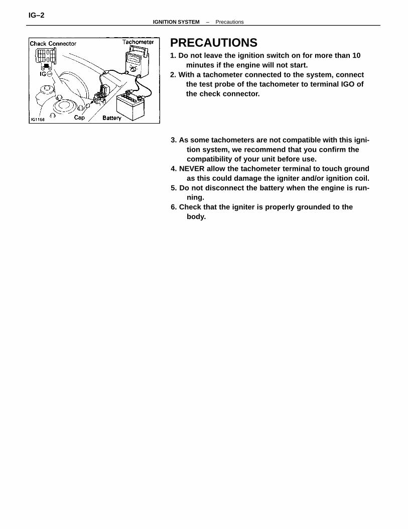
PRECAUTIONS1. Do not leave the ignition switch on for more than 10
minutes if the engine will not start.2. With a tachometer connected to the system, connect
the test probe of the tachometer to terminal IGO ofthe check connector.
–IGNITION SYSTEM PrecautionsIG–2
Incorrect ignition timingIgnition problems• Ignition coil• Igniter• Distributor• High–tension cords
Ignition wiring disconnected or broken
Spark plug faultyIgnition wiring faultyIncorrect ignition timingIgnition problems• Ignition coil• Igniter• Distributor
High–tension cords
Reset timingInspect coilInspect igniterInspect distributorInspect high–tension cordsInspect wiring
Inspect coilInspect igniterInspect distributorInspect high–tension cords
Spark plug faultyIgnition wiring faultyIncorrect ignition timing
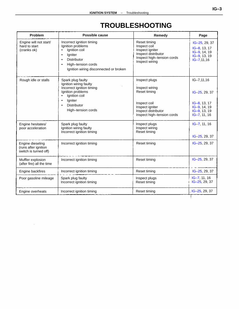
Engine will not start/hard to start(cranks ok)
TROUBLESHOOTING
Engine dieseling(runs after ignitionswitch is turned off)
Spark plug faultyIncorrect ignition timing
Inspect plugs.Inspect wiringReset timing
Inspect plugsInspect wiringReset timing
IG–8, 13, 17IG–9, 14, 19IG–9, 13, 19IG–7, 11, 16
IG–8, 13, 17IG–9, 14, 19IG–9, 13, 19IG–7,11,16
Muffler explosion(after fire) all the time
Engine hesitates/poor acceleration
Inspect plugsReset timing
IG–7, 11, 16IG–25, 29, 37
Incorrect ignition timing
Incorrect ignition timing
Incorrect ignition timing
Incorrect ignition timing
Poor gasoline mileage
Rough idle or stalls
, IG–25, 29, 37
IG–25, 29, 37
Engine overheats
Engine backfires
Possible cause
Reset timing
IG–25, 29, 37
IG–25, 29, 37
IG–25, 29, 37
IG–25, 29, 37
IG–25, 29, 37Reset timing
Reset timing
Reset timing
IG–7, 11, 16
lG–7,11,16
Problem Remedy Page
–IGNITION SYSTEM TroubleshootingIG–3
IGNITION SYSTEM CIRCUIT
–IGNITION SYSTEM Ignition System CircuitIG–4
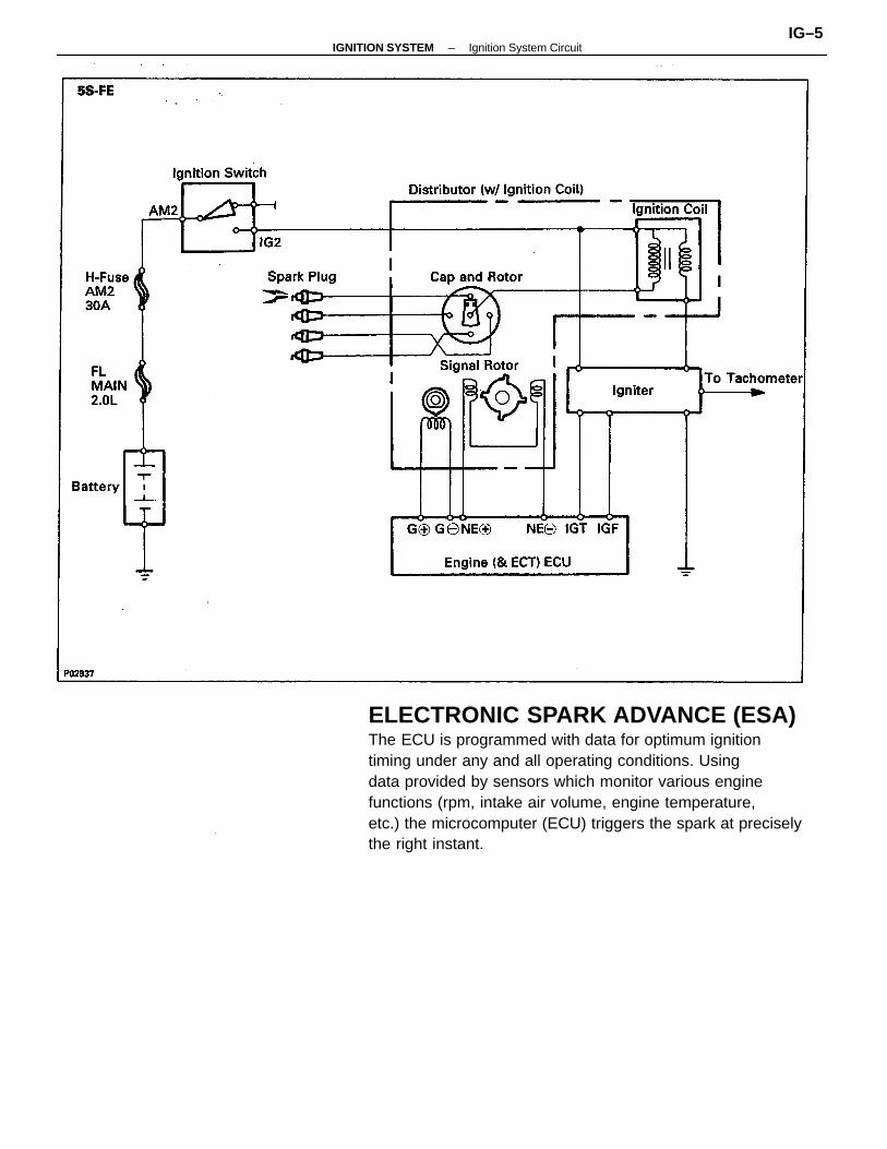
ELECTRONIC SPARK ADVANCE (ESA)The ECU is programmed with data for optimum ignitiontiming under any and all operating conditions. Usingdata provided by sensors which monitor various enginefunctions (rpm, intake air volume, engine temperature,etc.) the microcomputer (ECU) triggers the spark at preciselythe right instant.
–IGNITION SYSTEM Ignition System CircuitIG–5
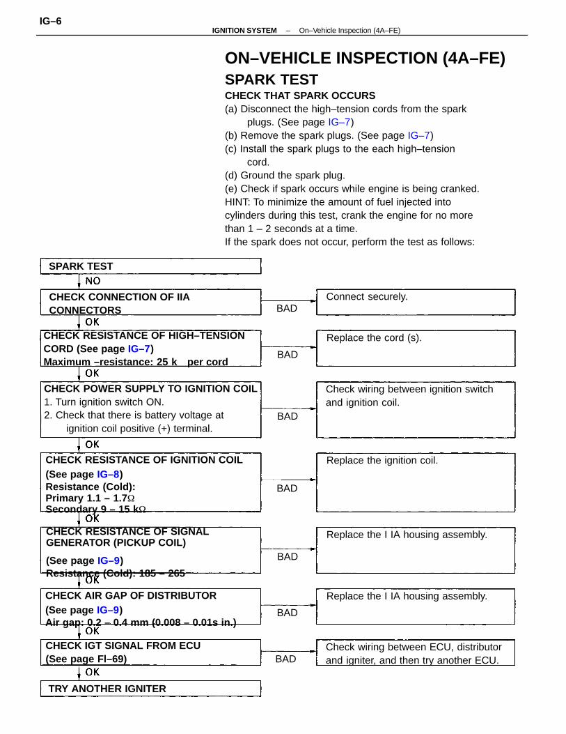
ON–VEHICLE INSPECTION (4A–FE)SPARK TESTCHECK THAT SPARK OCCURS(a) Disconnect the high–tension cords from the spark
plugs. (See page IG–7)(b) Remove the spark plugs. (See page IG–7)(c) Install the spark plugs to the each high–tension
cord.(d) Ground the spark plug.(e) Check if spark occurs while engine is being cranked.HINT: To minimize the amount of fuel injected intocylinders during this test, crank the engine for no morethan 1 – 2 seconds at a time.If the spark does not occur, perform the test as follows:
CHECK RESISTANCE OF IGNITION COIL(See page IG–8)Resistance (Cold):Primary 1.1 – 1.7
Secondary 9 – 15 k
CHECK POWER SUPPLY TO IGNITION COIL1. Turn ignition switch ON.2. Check that there is battery voltage at
ignition coil positive (+) terminal.
CHECK RESISTANCE OF SIGNALGENERATOR (PICKUP COIL)
(See page IG–9)Resistance (Cold): 185 – 265
CHECK AIR GAP OF DISTRIBUTOR(See page IG–9)Air gap: 0.2 – 0.4 mm (0.008 – 0.01s in.)
CHECK RESISTANCE OF HIGH–TENSIONCORD (See page IG–7)Maximum –resistance: 25 k per cord
Check wiring between ECU, distributorand igniter, and then try another ECU.
Check wiring between ignition switchand ignition coil.
CHECK IGT SIGNAL FROM ECU(See page Fl–69)
CHECK CONNECTION OF IIACONNECTORS
Replace the I IA housing assembly.
Replace the I IA housing assembly.
Replace the ignition coil.
TRY ANOTHER IGNITER
Replace the cord (s).
Connect securely.
SPARK TEST
BAD
BAD
BAD
BAD
BAD
BAD
BAD
–IGNITION SYSTEM On–Vehicle Inspection (4A–FE)IG–6
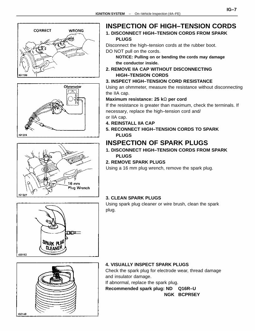
INSPECTION OF HIGH–TENSION CORDS1. DISCONNECT HIGH–TENSION CORDS FROM SPARK
PLUGSDisconnect the high–tension cords at the rubber boot.DO NOT pull on the cords.
NOTICE: Pulling on or bending the cords may damagethe conductor inside.
2. REMOVE IIA CAP WITHOUT DISCONNECTINGHIGH–TENSION CORDS
3. INSPECT HIGH–TENSION CORD RESISTANCEUsing an ohmmeter, measure the resistance without disconnectingthe IIA cap.Maximum resistance: 25 k Ω per cordIf the resistance is greater than maximum, check the terminals. Ifnecessary, replace the high–tension cord and/or IIA cap.4. REINSTALL IIA CAP5. RECONNECT HIGH–TENSION CORDS TO SPARK
PLUGS
INSPECTION OF SPARK PLUGS1. DISCONNECT HIGH–TENSION CORDS FROM SPARK
PLUGS2. REMOVE SPARK PLUGSUsing a 16 mm plug wrench, remove the spark plug.
4. VISUALLY INSPECT SPARK PLUGSCheck the spark plug for electrode wear, thread damageand insulator damage.If abnormal, replace the spark plug.Recommended spark plug: ND Q16R–U NGK BCPR5EY
3. CLEAN SPARK PLUGSUsing spark plug cleaner or wire brush, clean the sparkplug.
–IGNITION SYSTEM On–Vehicle Inspection (4A–FE)IG–7
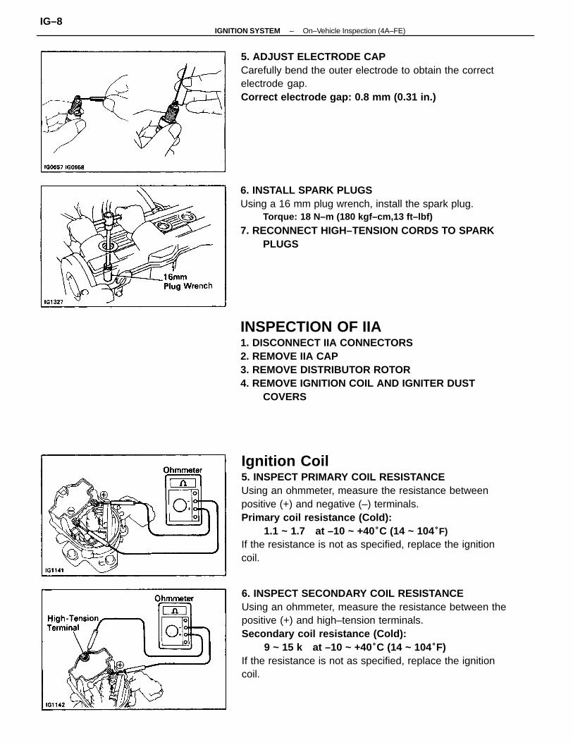
Ignition Coil5. INSPECT PRIMARY COIL RESISTANCEUsing an ohmmeter, measure the resistance betweenpositive (+) and negative (–) terminals.Primary coil resistance (Cold):
1.1 ~ 1.7 at –10 ~ +40°C (14 ~ 104°F)If the resistance is not as specified, replace the ignitioncoil.
6. INSPECT SECONDARY COIL RESISTANCEUsing an ohmmeter, measure the resistance between thepositive (+) and high–tension terminals.Secondary coil resistance (Cold):
9 ~ 15 k at –10 ~ +40°C (14 ~ 104°F)If the resistance is not as specified, replace the ignitioncoil.
INSPECTION OF IIA1. DISCONNECT IIA CONNECTORS2. REMOVE IIA CAP3. REMOVE DISTRIBUTOR ROTOR4. REMOVE IGNITION COIL AND IGNITER DUST
COVERS
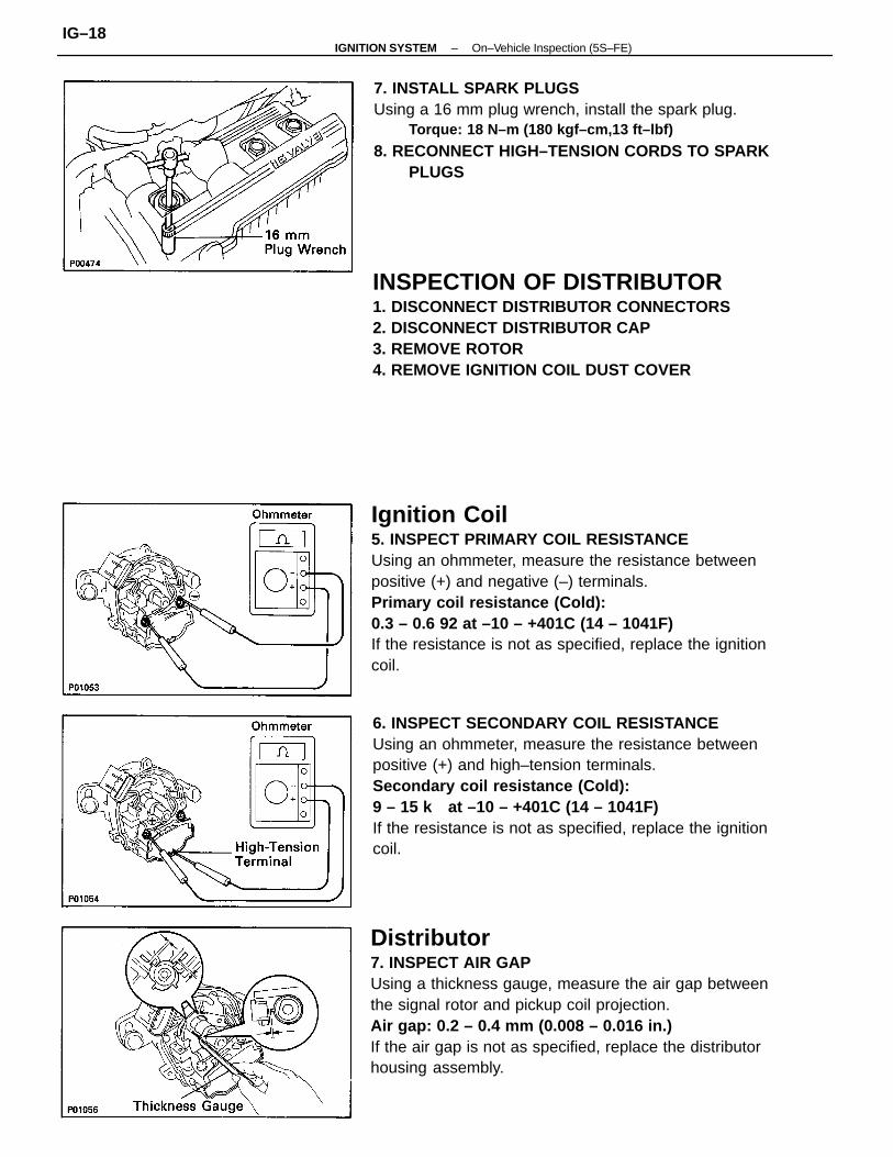
6. INSTALL SPARK PLUGSUsing a 16 mm plug wrench, install the spark plug.
Torque: 18 N–m (180 kgf–cm,13 ft–lbf)
7. RECONNECT HIGH–TENSION CORDS TO SPARKPLUGS
5. ADJUST ELECTRODE CAPCarefully bend the outer electrode to obtain the correctelectrode gap.Correct electrode gap: 0.8 mm (0.31 in.)
–IGNITION SYSTEM On–Vehicle Inspection (4A–FE)IG–8
9. REINSTALL IGNITION COIL AND IGNITER DUSTCOVERS
10. REINSTALL DISTRIBUTOR ROTOR11. REINSTALL IIA CAP12. RECONNECT IIA CONNECTORS
Igniter(See procedure Spark Test on page IG–6)
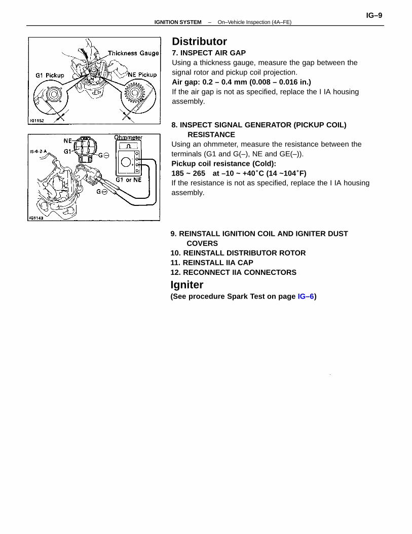
8. INSPECT SIGNAL GENERATOR (PICKUP COIL)RESISTANCE
Using an ohmmeter, measure the resistance between theterminals (G1 and G(–), NE and GE(–)).Pickup coil resistance (Cold):185 ~ 265 at –10 ~ +40°C (14 ~104°F)If the resistance is not as specified, replace the I IA housingassembly.
Distributor7. INSPECT AIR GAPUsing a thickness gauge, measure the gap between thesignal rotor and pickup coil projection.Air gap: 0.2 – 0.4 mm (0.008 – 0.016 in.)If the air gap is not as specified, replace the I IA housingassembly.
–IGNITION SYSTEM On–Vehicle Inspection (4A–FE)IG–9
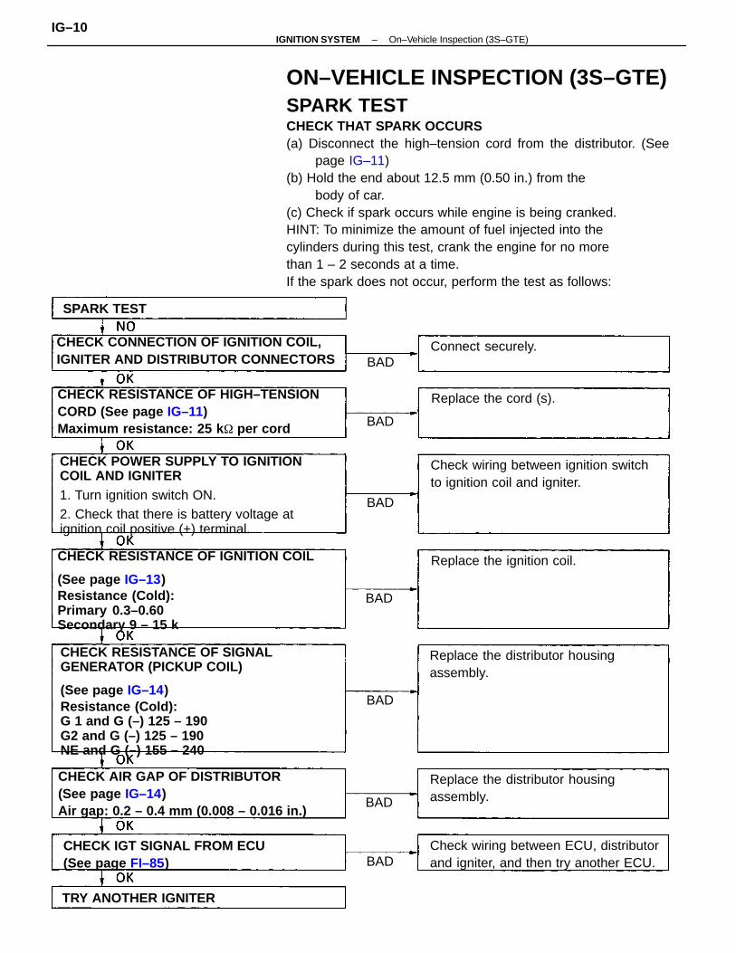
ON–VEHICLE INSPECTION (3S–GTE)SPARK TESTCHECK THAT SPARK OCCURS(a) Disconnect the high–tension cord from the distributor. (See
page IG–11)(b) Hold the end about 12.5 mm (0.50 in.) from the
body of car.(c) Check if spark occurs while engine is being cranked.HINT: To minimize the amount of fuel injected into thecylinders during this test, crank the engine for no morethan 1 – 2 seconds at a time.If the spark does not occur, perform the test as follows:
CHECK RESISTANCE OF SIGNALGENERATOR (PICKUP COIL)
(See page IG–14)Resistance (Cold):G 1 and G (–) 125 – 190
G2 and G (–) 125 – 190
NE and G (–) 155 – 240
CHECK RESISTANCE OF IGNITION COIL
(See page IG–13)Resistance (Cold):Primary 0.3–0.60Secondary 9 – 15 k
CHECK POWER SUPPLY TO IGNITIONCOIL AND IGNITER1. Turn ignition switch ON.2. Check that there is battery voltage atignition coil positive (+) terminal.
CHECK RESISTANCE OF HIGH–TENSIONCORD (See page IG–11)Maximum resistance: 25 k per cord
CHECK AIR GAP OF DISTRIBUTOR(See page IG–14)Air gap: 0.2 – 0.4 mm (0.008 – 0.016 in.)
CHECK CONNECTION OF IGNITION COIL,IGNITER AND DISTRIBUTOR CONNECTORS
Check wiring between ECU, distributorand igniter, and then try another ECU.
Check wiring between ignition switchto ignition coil and igniter.
Replace the distributor housingassembly.
Replace the distributor housingassembly.
CHECK IGT SIGNAL FROM ECU(See page FI–85)
Replace the ignition coil.
TRY ANOTHER IGNITER
Replace the cord (s).
Connect securely.
SPARK TEST
BAD
BAD
BAD
BAD
BAD
BAD
BAD
–IGNITION SYSTEM On–Vehicle Inspection (3S–GTE)IG–10
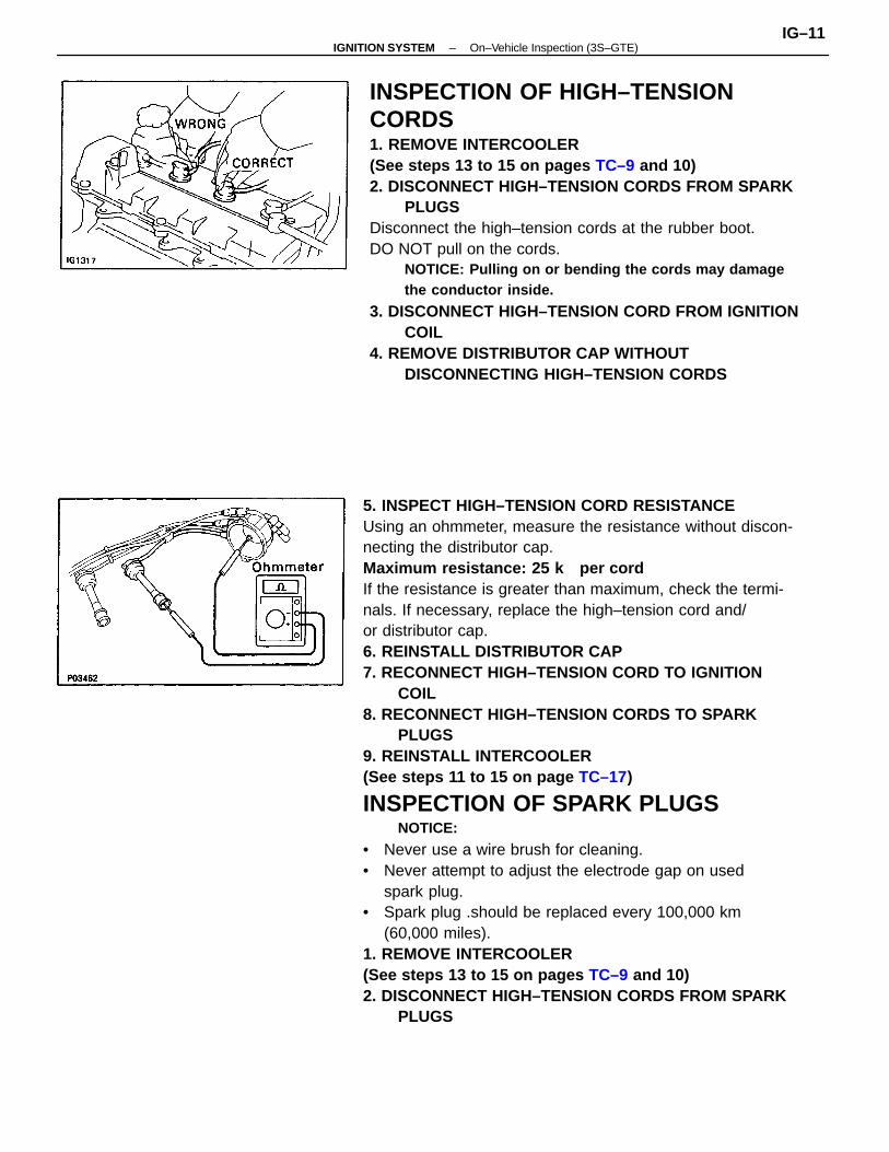
5. INSPECT HIGH–TENSION CORD RESISTANCEUsing an ohmmeter, measure the resistance without discon-necting the distributor cap.Maximum resistance: 25 k per cordIf the resistance is greater than maximum, check the termi-nals. If necessary, replace the high–tension cord and/or distributor cap.6. REINSTALL DISTRIBUTOR CAP7. RECONNECT HIGH–TENSION CORD TO IGNITION
COIL8. RECONNECT HIGH–TENSION CORDS TO SPARK
PLUGS9. REINSTALL INTERCOOLER(See steps 11 to 15 on page TC–17)
INSPECTION OF SPARK PLUGSNOTICE:
• Never use a wire brush for cleaning.• Never attempt to adjust the electrode gap on used
spark plug.• Spark plug .should be replaced every 100,000 km
(60,000 miles).1. REMOVE INTERCOOLER(See steps 13 to 15 on pages TC–9 and 10)2. DISCONNECT HIGH–TENSION CORDS FROM SPARK
PLUGS
INSPECTION OF HIGH–TENSIONCORDS1. REMOVE INTERCOOLER(See steps 13 to 15 on pages TC–9 and 10)2. DISCONNECT HIGH–TENSION CORDS FROM SPARK
PLUGSDisconnect the high–tension cords at the rubber boot.DO NOT pull on the cords.
NOTICE: Pulling on or bending the cords may damagethe conductor inside.
3. DISCONNECT HIGH–TENSION CORD FROM IGNITIONCOIL
4. REMOVE DISTRIBUTOR CAP WITHOUTDISCONNECTING HIGH–TENSION CORDS
–IGNITION SYSTEM On–Vehicle Inspection (3S–GTE)IG–11
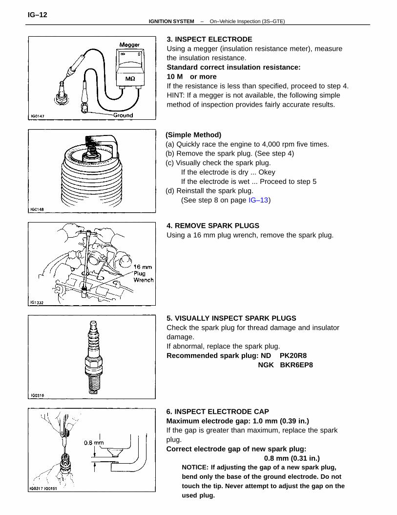
6. INSPECT ELECTRODE CAPMaximum electrode gap: 1.0 mm (0.39 in.)If the gap is greater than maximum, replace the sparkplug.Correct electrode gap of new spark plug: 0.8 mm (0.31 in.)
NOTICE: If adjusting the gap of a new spark plug,bend only the base of the ground electrode. Do nottouch the tip. Never attempt to adjust the gap on theused plug.
3. INSPECT ELECTRODEUsing a megger (insulation resistance meter), measurethe insulation resistance.Standard correct insulation resistance:10 M or moreIf the resistance is less than specified, proceed to step 4.HINT: If a megger is not available, the following simplemethod of inspection provides fairly accurate results.
(Simple Method)(a) Quickly race the engine to 4,000 rpm five times.(b) Remove the spark plug. (See step 4)(c) Visually check the spark plug.
If the electrode is dry ... OkeyIf the electrode is wet ... Proceed to step 5
(d) Reinstall the spark plug.(See step 8 on page IG–13)
5. VISUALLY INSPECT SPARK PLUGSCheck the spark plug for thread damage and insulatordamage.If abnormal, replace the spark plug.Recommended spark plug: ND PK20R8 NGK BKR6EP8
4. REMOVE SPARK PLUGSUsing a 16 mm plug wrench, remove the spark plug.
–IGNITION SYSTEM On–Vehicle Inspection (3S–GTE)IG–12
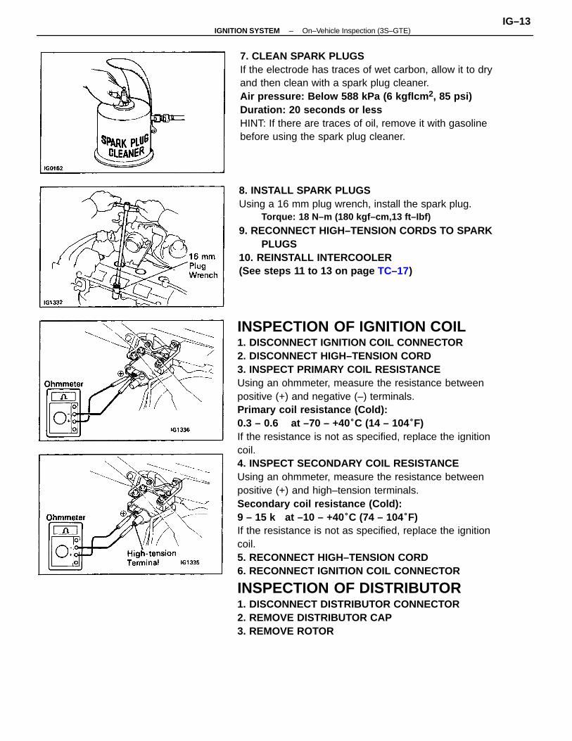
INSPECTION OF IGNITION COIL1. DISCONNECT IGNITION COIL CONNECTOR2. DISCONNECT HIGH–TENSION CORD3. INSPECT PRIMARY COIL RESISTANCEUsing an ohmmeter, measure the resistance betweenpositive (+) and negative (–) terminals.Primary coil resistance (Cold):0.3 – 0.6 at –70 – +40°C (14 – 104°F)If the resistance is not as specified, replace the ignitioncoil.4. INSPECT SECONDARY COIL RESISTANCEUsing an ohmmeter, measure the resistance betweenpositive (+) and high–tension terminals.Secondary coil resistance (Cold):9 – 15 k at –10 – +40°C (74 – 104°F)If the resistance is not as specified, replace the ignitioncoil.5. RECONNECT HIGH–TENSION CORD6. RECONNECT IGNITION COIL CONNECTOR
INSPECTION OF DISTRIBUTOR1. DISCONNECT DISTRIBUTOR CONNECTOR2. REMOVE DISTRIBUTOR CAP3. REMOVE ROTOR
8. INSTALL SPARK PLUGSUsing a 16 mm plug wrench, install the spark plug.
Torque: 18 N–m (180 kgf–cm,13 ft–Ibf)
9. RECONNECT HIGH–TENSION CORDS TO SPARKPLUGS
10. REINSTALL INTERCOOLER(See steps 11 to 13 on page TC–17)
7. CLEAN SPARK PLUGSIf the electrode has traces of wet carbon, allow it to dryand then clean with a spark plug cleaner.Air pressure: Below 588 kPa (6 kgflcm 2, 85 psi)Duration: 20 seconds or lessHINT: If there are traces of oil, remove it with gasolinebefore using the spark plug cleaner.
–IGNITION SYSTEM On–Vehicle Inspection (3S–GTE)IG–13
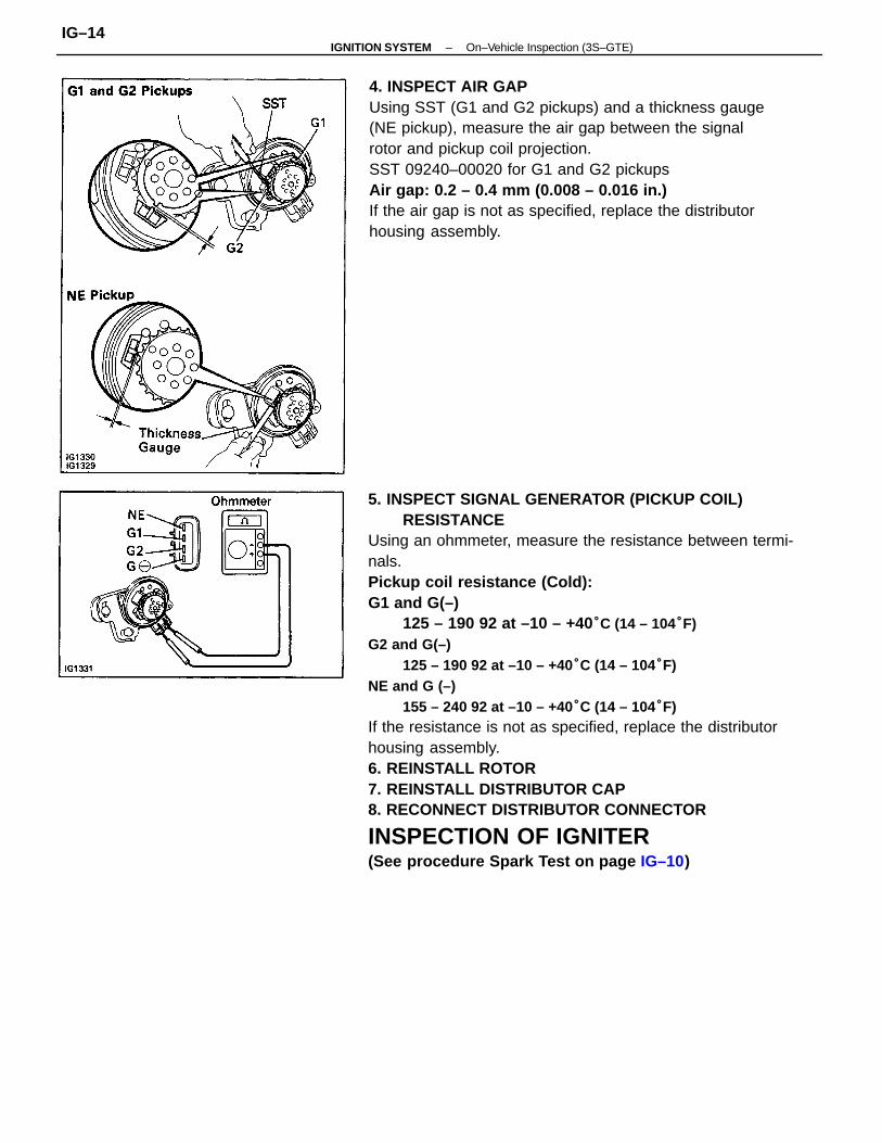
5. INSPECT SIGNAL GENERATOR (PICKUP COIL)RESISTANCE
Using an ohmmeter, measure the resistance between termi-nals.Pickup coil resistance (Cold):G1 and G(–)
125 – 190 92 at –10 – +40°C (14 – 104°F)G2 and G(–)
125 – 190 92 at –10 – +40°C (14 – 104°F)NE and G (–)
155 – 240 92 at –10 – +40°C (14 – 104°F)If the resistance is not as specified, replace the distributorhousing assembly.6. REINSTALL ROTOR7. REINSTALL DISTRIBUTOR CAP8. RECONNECT DISTRIBUTOR CONNECTOR
INSPECTION OF IGNITER(See procedure Spark Test on page IG–10)
4. INSPECT AIR GAPUsing SST (G1 and G2 pickups) and a thickness gauge(NE pickup), measure the air gap between the signalrotor and pickup coil projection.SST 09240–00020 for G1 and G2 pickupsAir gap: 0.2 – 0.4 mm (0.008 – 0.016 in.)If the air gap is not as specified, replace the distributorhousing assembly.
–IGNITION SYSTEM On–Vehicle Inspection (3S–GTE)IG–14
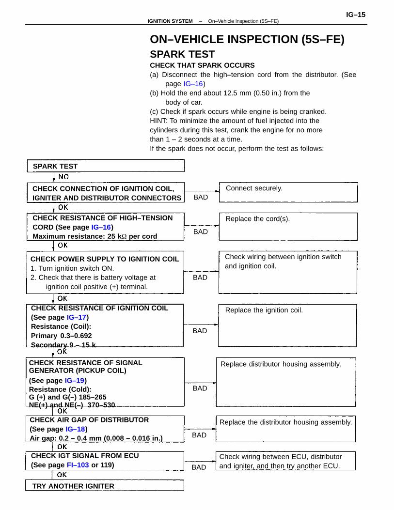
ON–VEHICLE INSPECTION (5S–FE)SPARK TESTCHECK THAT SPARK OCCURS(a) Disconnect the high–tension cord from the distributor. (See
page IG–16)(b) Hold the end about 12.5 mm (0.50 in.) from the
body of car.(c) Check if spark occurs while engine is being cranked.HINT: To minimize the amount of fuel injected into thecylinders during this test, crank the engine for no morethan 1 – 2 seconds at a time.If the spark does not occur, perform the test as follows:
CHECK RESISTANCE OF IGNITION COIL(See page IG–17)Resistance (Coil):Primary 0.3–0.692Secondary 9 – 15 k
CHECK RESISTANCE OF SIGNALGENERATOR (PICKUP COIL)(See page IG–19)Resistance (Cold):G (+) and G(–) 185–265
NE(+) and NE(–) 370–530
CHECK POWER SUPPLY TO IGNITION COIL1. Turn ignition switch ON.2. Check that there is battery voltage at
ignition coil positive (+) terminal.
CHECK RESISTANCE OF HIGH–TENSIONCORD (See page IG–16)Maximum resistance: 25 k per cord
CHECK AIR GAP OF DISTRIBUTOR(See page IG–18)Air gap: 0.2 – 0.4 mm (0.008 – 0.016 in.)
CHECK CONNECTION OF IGNITION COIL,IGNITER AND DISTRIBUTOR CONNECTORS
Check wiring between ECU, distributorand igniter, and then try another ECU.
Check wiring between ignition switchand ignition coil.
CHECK IGT SIGNAL FROM ECU(See page FI–103 or 119)
Replace the distributor housing assembly.
Replace distributor housing assembly.
Replace the ignition coil.
TRY ANOTHER IGNITER
Replace the cord(s).
Connect securely.
SPARK TEST
BAD
BAD
BAD
BAD
BAD
BAD
BAD
–IGNITION SYSTEM On–Vehicle Inspection (5S–FE)IG–15
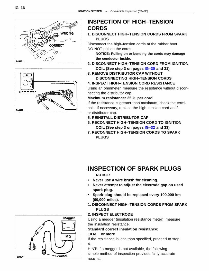
INSPECTION OF HIGH–TENSIONCORDS1. DISCONNECT HIGH–TENSION CORDS FROM SPARK
PLUGSDisconnect the high–tension cords at the rubber boot.DO NOT pull on the cords.
NOTICE: Pulling on or bending the cords may damagethe conductor inside.
2. DISCONNECT HIGH–TENSION CORD FROM IGNITIONCOIL (See step 3 on pages IG–30 and 31)
3. REMOVE DISTRIBUTOR CAP WITHOUTDISCONNECTING HIGH–TENSION CORDS
4. INSPECT HIGH–TENSION CORD RESISTANCEUsing an ohmmeter, measure the resistance without discon-necting the distributor cap.Maximum resistance: 25 k per cordIf the resistance is greater than maximum, check the termi-nals. If necessary, replace the high–tension cord and/or distributor cap.5. REINSTALL DISTRIBUTOR CAP6. RECONNECT HIGH–TENSION CORD TO IGNITION
COIL (See step 3 on pages IG–32 and 33)7. RECONNECT HIGH–TENSION CORDS TO SPARK
PLUGS
INSPECTION OF SPARK PLUGSNOTICE:
• Never use a wire brush for cleaning.• Never attempt to adjust the electrode gap on used
spark plug.• Spark plug should be replaced every 100,000 km
(60,000 miles).1. DISCONNECT HIGH–TENSION CORDS FROM SPARK
PLUGS2. INSPECT ELECTRODEUsing a megger (insulation resistance meter), measurethe insulation resistance.Standard correct insulation resistance:10 M or moreIf the resistance is less than specified, proceed to step4.HINT: If a megger is not available, the followingsimple method of inspection provides fairly accurateresu Its.
–IGNITION SYSTEM On–Vehicle Inspection (5S–FE)IG–16
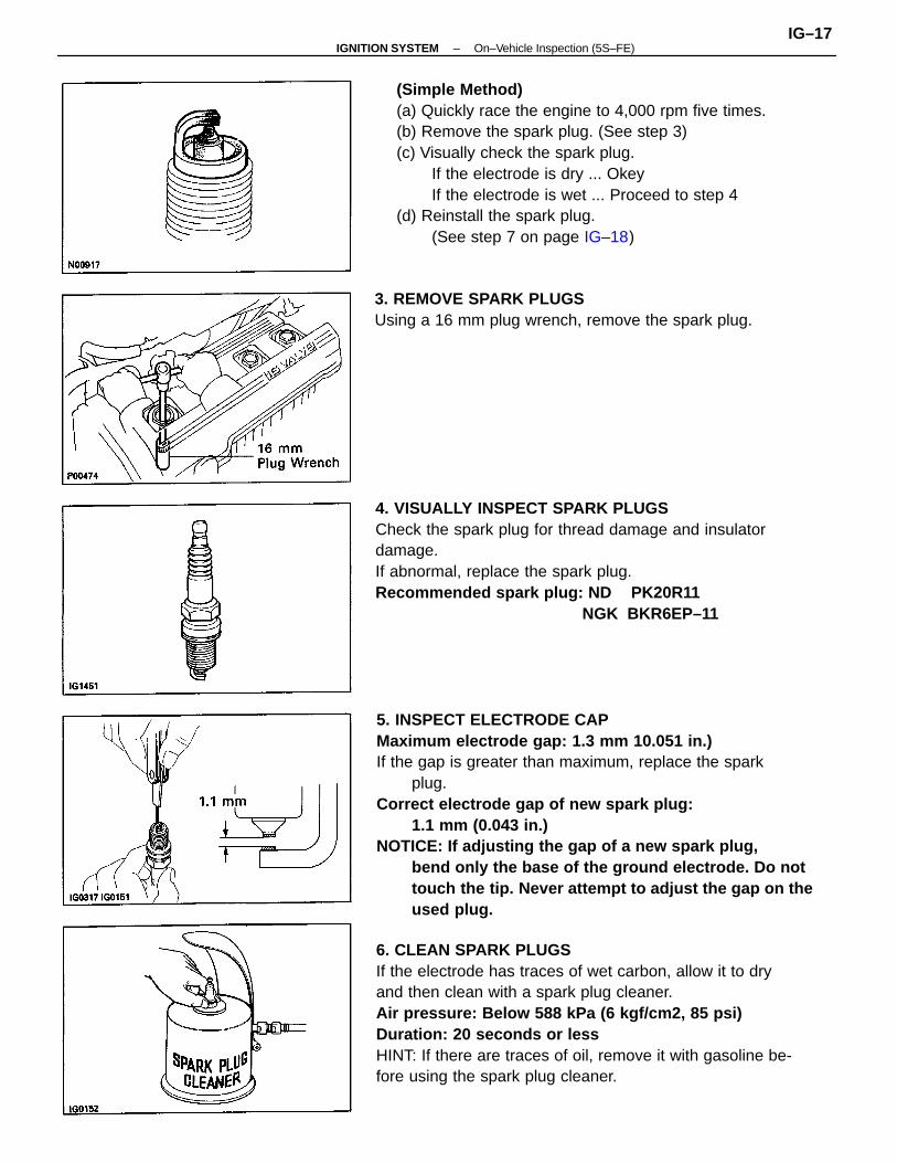
5. INSPECT ELECTRODE CAPMaximum electrode gap: 1.3 mm 10.051 in.)If the gap is greater than maximum, replace the spark
plug.Correct electrode gap of new spark plug:
1.1 mm (0.043 in.)NOTICE: If adjusting the gap of a new spark plug,
bend only the base of the ground electrode. Do nottouch the tip. Never attempt to adjust the gap on theused plug.
(Simple Method)(a) Quickly race the engine to 4,000 rpm five times.(b) Remove the spark plug. (See step 3)(c) Visually check the spark plug.
If the electrode is dry ... OkeyIf the electrode is wet ... Proceed to step 4
(d) Reinstall the spark plug.(See step 7 on page IG–18)
6. CLEAN SPARK PLUGSIf the electrode has traces of wet carbon, allow it to dryand then clean with a spark plug cleaner.Air pressure: Below 588 kPa (6 kgf/cm2, 85 psi)Duration: 20 seconds or lessHINT: If there are traces of oil, remove it with gasoline be-fore using the spark plug cleaner.
4. VISUALLY INSPECT SPARK PLUGSCheck the spark plug for thread damage and insulatordamage.If abnormal, replace the spark plug.Recommended spark plug: ND PK20R11 NGK BKR6EP–11
3. REMOVE SPARK PLUGSUsing a 16 mm plug wrench, remove the spark plug.
–IGNITION SYSTEM On–Vehicle Inspection (5S–FE)IG–17
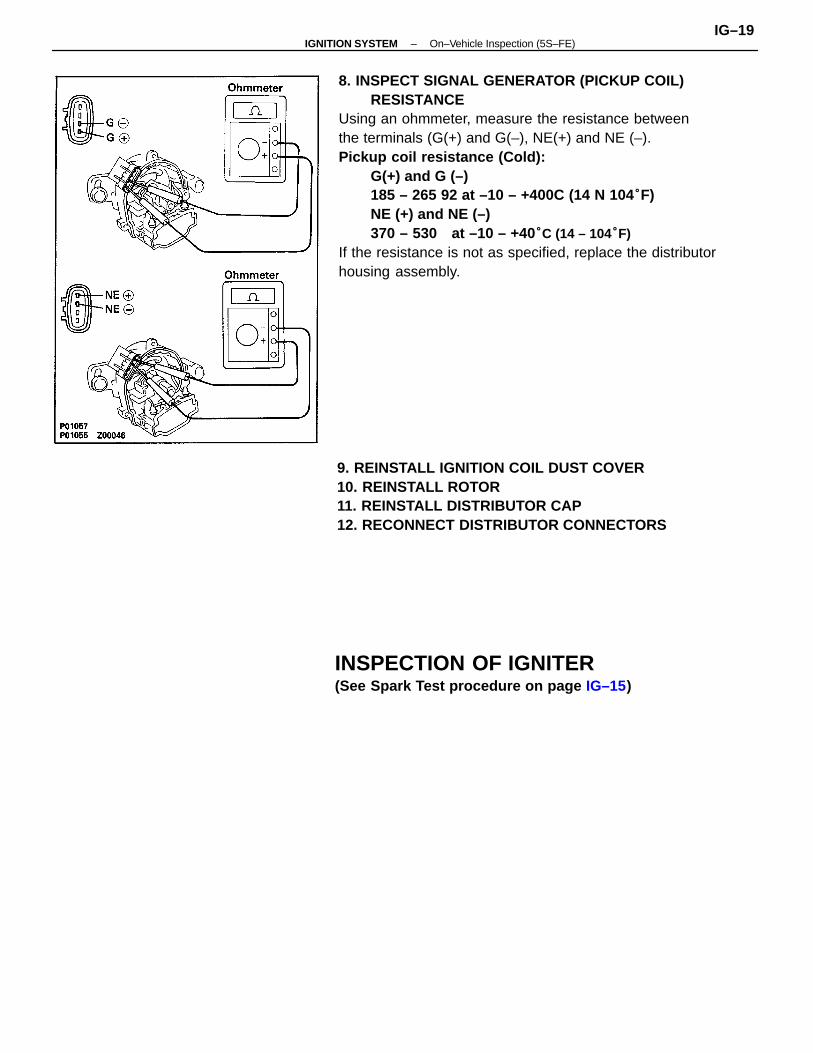
Ignition Coil5. INSPECT PRIMARY COIL RESISTANCEUsing an ohmmeter, measure the resistance betweenpositive (+) and negative (–) terminals.Primary coil resistance (Cold):0.3 – 0.6 92 at –10 – +401C (14 – 1041F)If the resistance is not as specified, replace the ignitioncoil.
Distributor7. INSPECT AIR GAPUsing a thickness gauge, measure the air gap betweenthe signal rotor and pickup coil projection.Air gap: 0.2 – 0.4 mm (0.008 – 0.016 in.)If the air gap is not as specified, replace the distributorhousing assembly.
6. INSPECT SECONDARY COIL RESISTANCEUsing an ohmmeter, measure the resistance betweenpositive (+) and high–tension terminals.Secondary coil resistance (Cold):9 – 15 k at –10 – +401C (14 – 1041F)If the resistance is not as specified, replace the ignitioncoil.
INSPECTION OF DISTRIBUTOR1. DISCONNECT DISTRIBUTOR CONNECTORS2. DISCONNECT DISTRIBUTOR CAP3. REMOVE ROTOR4. REMOVE IGNITION COIL DUST COVER
7. INSTALL SPARK PLUGSUsing a 16 mm plug wrench, install the spark plug.
Torque: 18 N–m (180 kgf–cm,13 ft–lbf)
8. RECONNECT HIGH–TENSION CORDS TO SPARKPLUGS
–IGNITION SYSTEM On–Vehicle Inspection (5S–FE)IG–18
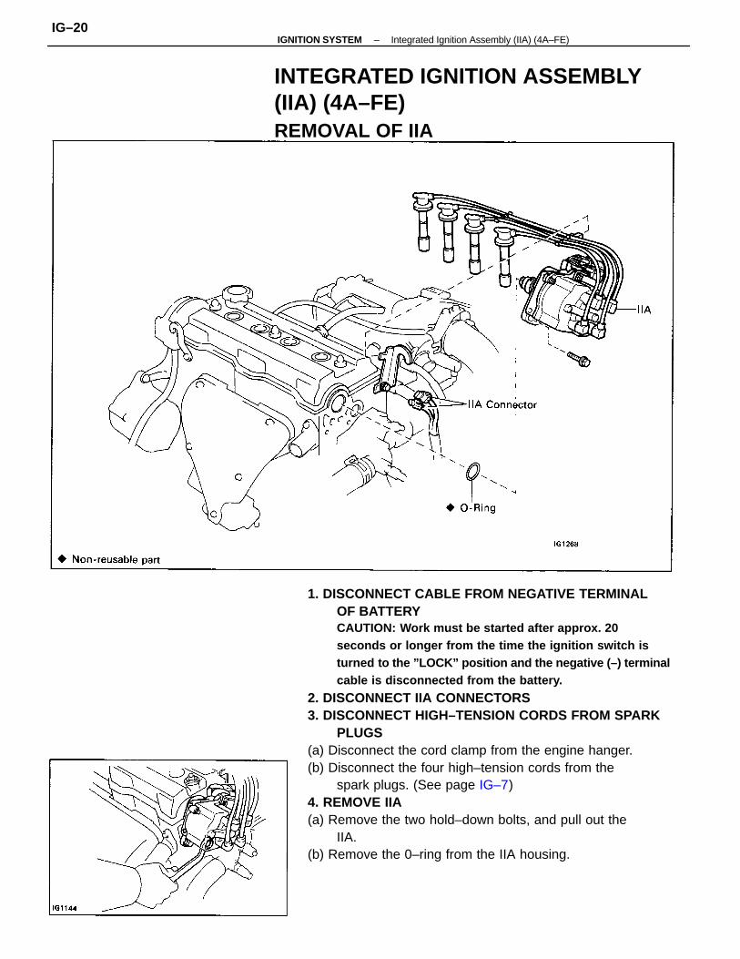
8. INSPECT SIGNAL GENERATOR (PICKUP COIL)RESISTANCE
Using an ohmmeter, measure the resistance betweenthe terminals (G(+) and G(–), NE(+) and NE (–).Pickup coil resistance (Cold):
G(+) and G (–)185 – 265 92 at –10 – +400C (14 N 104°F)NE (+) and NE (–)370 – 530 at –10 – +40°C (14 – 104°F)
If the resistance is not as specified, replace the distributorhousing assembly.
9. REINSTALL IGNITION COIL DUST COVER10. REINSTALL ROTOR11. REINSTALL DISTRIBUTOR CAP12. RECONNECT DISTRIBUTOR CONNECTORS
INSPECTION OF IGNITER(See Spark Test procedure on page IG–15)
–IGNITION SYSTEM On–Vehicle Inspection (5S–FE)IG–19
1. DISCONNECT CABLE FROM NEGATIVE TERMINALOF BATTERYCAUTION: Work must be started after approx. 20seconds or longer from the time the ignition switch isturned to the ”LOCK” position and the negative (–) terminalcable is disconnected from the battery.
2. DISCONNECT IIA CONNECTORS3. DISCONNECT HIGH–TENSION CORDS FROM SPARK
PLUGS(a) Disconnect the cord clamp from the engine hanger.(b) Disconnect the four high–tension cords from the
spark plugs. (See page IG–7)4. REMOVE IIA(a) Remove the two hold–down bolts, and pull out the
IIA.(b) Remove the 0–ring from the IIA housing.
INTEGRATED IGNITION ASSEMBLY(IIA) (4A–FE)REMOVAL OF IIA
–IGNITION SYSTEM Integrated Ignition Assembly (IIA) (4A–FE)IG–20
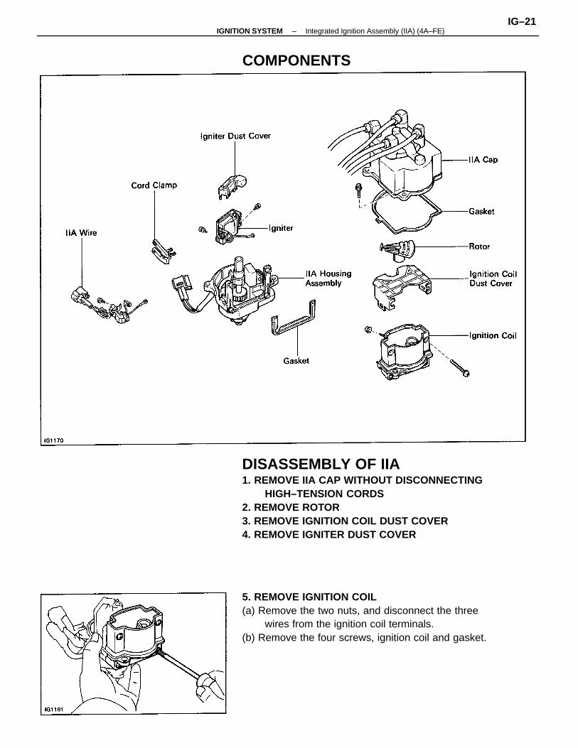
DISASSEMBLY OF IIA1. REMOVE IIA CAP WITHOUT DISCONNECTING
HIGH–TENSION CORDS2. REMOVE ROTOR3. REMOVE IGNITION COIL DUST COVER4. REMOVE IGNITER DUST COVER
5. REMOVE IGNITION COIL(a) Remove the two nuts, and disconnect the three
wires from the ignition coil terminals.(b) Remove the four screws, ignition coil and gasket.
COMPONENTS
–IGNITION SYSTEM Integrated Ignition Assembly (IIA) (4A–FE)IG–21
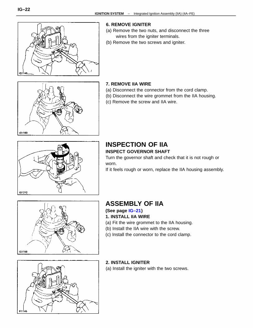
INSPECTION OF IIAINSPECT GOVERNOR SHAFTTurn the governor shaft and check that it is not rough orworn.If it feels rough or worn, replace the IIA housing assembly.
ASSEMBLY OF IIA(See page IG–21)1. INSTALL IIA WIRE(a) Fit the wire grommet to the IIA housing.(b) Install the IIA wire with the screw.(c) Install the connector to the cord clamp.
7. REMOVE IIA WIRE(a) Disconnect the connector from the cord clamp.(b) Disconnect the wire grommet from the IIA housing.(c) Remove the screw and IIA wire.
6. REMOVE IGNITER(a) Remove the two nuts, and disconnect the three
wires from the igniter terminals.(b) Remove the two screws and igniter.
2. INSTALL IGNITER(a) Install the igniter with the two screws.
–IGNITION SYSTEM Integrated Ignition Assembly (IIA) (4A–FE)IG–22
NOTICE:
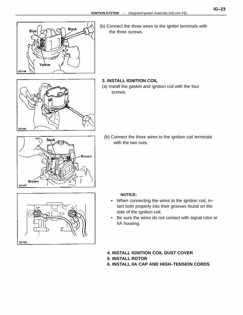
• When connecting the wires to the ignition coil, in–sert both properly into their grooves found on theside of the ignition coil.
• Be sure the wires do not contact with signal rotor orIIA housing.
4. INSTALL IGNITION COIL DUST COVER5. INSTALL ROTOR6. INSTALL IIA CAP AND HIGH–TENSION CORDS
3. INSTALL IGNITION COIL(a) Install the gasket and ignition coil with the four
screws.
(b) Connect the three wires to the igniter terminals withthe three screws.
(b) Connect the three wires to the ignition coil terminalswith the two nuts.
–IGNITION SYSTEM Integrated Ignition Assembly (IIA) (4A–FE)IG–23
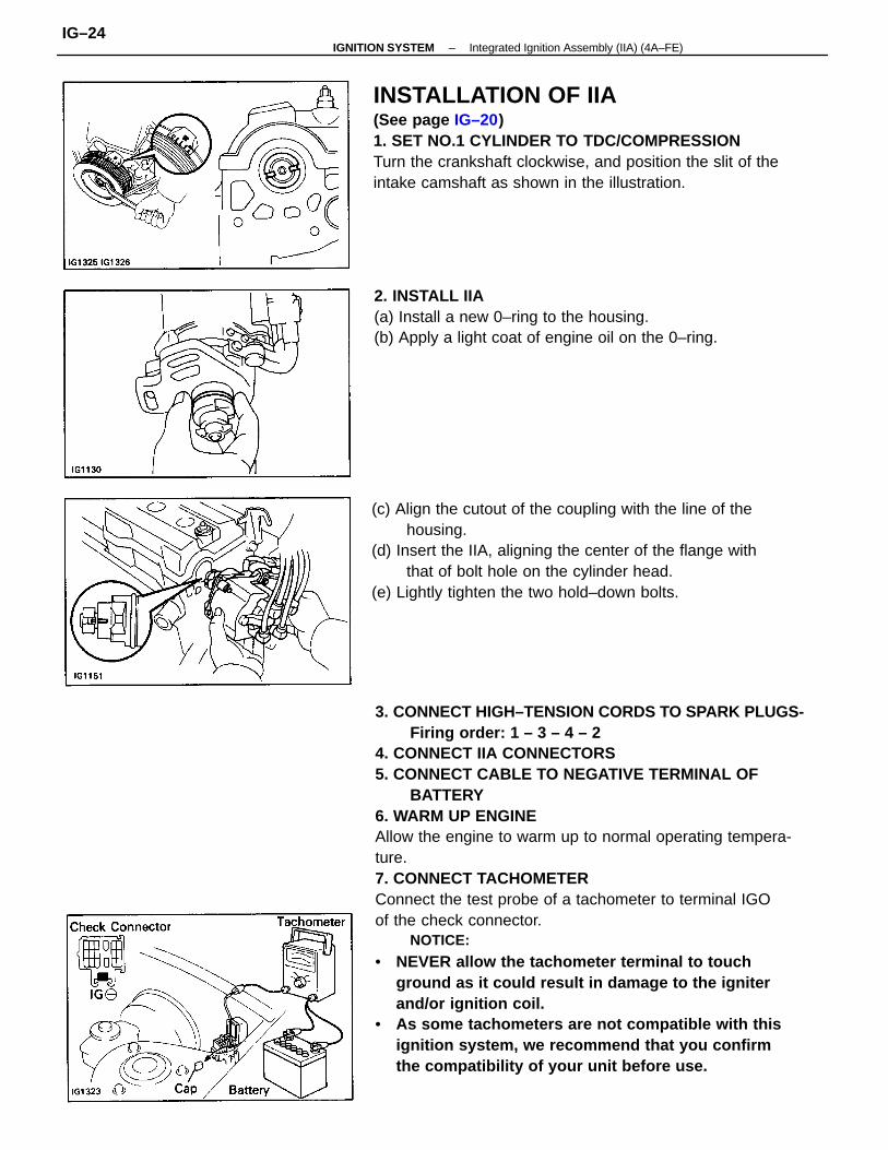
3. CONNECT HIGH–TENSION CORDS TO SPARK PLUGS-Firing order: 1 – 3 – 4 – 2
4. CONNECT IIA CONNECTORS5. CONNECT CABLE TO NEGATIVE TERMINAL OF
BATTERY6. WARM UP ENGINEAllow the engine to warm up to normal operating tempera-ture.7. CONNECT TACHOMETERConnect the test probe of a tachometer to terminal IGOof the check connector.
NOTICE:
• NEVER allow the tachometer terminal to touchground as it could result in damage to the igniterand/or ignition coil.
• As some tachometers are not compatible with thisignition system, we recommend that you confirmthe compatibility of your unit before use.
INSTALLATION OF IIA(See page IG–20)1. SET NO.1 CYLINDER TO TDC/COMPRESSIONTurn the crankshaft clockwise, and position the slit of theintake camshaft as shown in the illustration.
(c) Align the cutout of the coupling with the line of thehousing.
(d) Insert the IIA, aligning the center of the flange withthat of bolt hole on the cylinder head.
(e) Lightly tighten the two hold–down bolts.
2. INSTALL IIA(a) Install a new 0–ring to the housing.(b) Apply a light coat of engine oil on the 0–ring.
–IGNITION SYSTEM Integrated Ignition Assembly (IIA) (4A–FE)IG–24
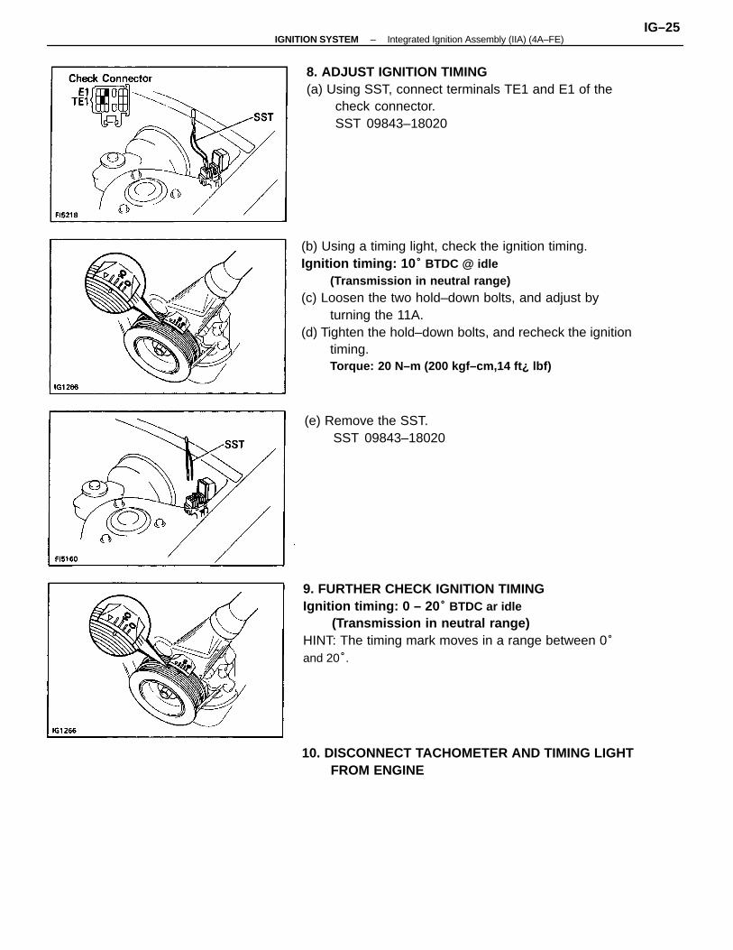
(b) Using a timing light, check the ignition timing.Ignition timing: 10 ° BTDC @ idle
(Transmission in neutral range)(c) Loosen the two hold–down bolts, and adjust by
turning the 11A.(d) Tighten the hold–down bolts, and recheck the ignition
timing.Torque: 20 N–m (200 kgf–cm,14 ft¿ lbf)
9. FURTHER CHECK IGNITION TIMINGIgnition timing: 0 – 20 ° BTDC ar idle
(Transmission in neutral range)HINT: The timing mark moves in a range between 0°and 20°.
8. ADJUST IGNITION TIMING(a) Using SST, connect terminals TE1 and E1 of the
check connector.SST 09843–18020
10. DISCONNECT TACHOMETER AND TIMING LIGHTFROM ENGINE
(e) Remove the SST.SST 09843–18020
–IGNITION SYSTEM Integrated Ignition Assembly (IIA) (4A–FE)IG–25
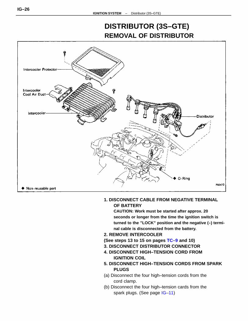
1. DISCONNECT CABLE FROM NEGATIVE TERMINALOF BATTERYCAUTION: Work must be started after approx. 20seconds or longer from the time the ignition switch isturned to the ”LOCK” position and the negative (–) termi-nal cable is disconnected from the battery.
2. REMOVE INTERCOOLER(See steps 13 to 15 on pages TC–9 and 10)3. DISCONNECT DISTRIBUTOR CONNECTOR4. DISCONNECT HIGH–TENSION CORD FROM
IGNITION COIL5. DISCONNECT HIGH–TENSION CORDS FROM SPARK
PLUGS(a) Disconnect the four high–tension cords from the
cord clamp.(b) Disconnect the four high–tension cards from the
spark plugs. (See page IG–11)
DISTRIBUTOR (3S–GTE)REMOVAL OF DISTRIBUTOR
–IGNITION SYSTEM Distributor (3S–GTE)IG–26
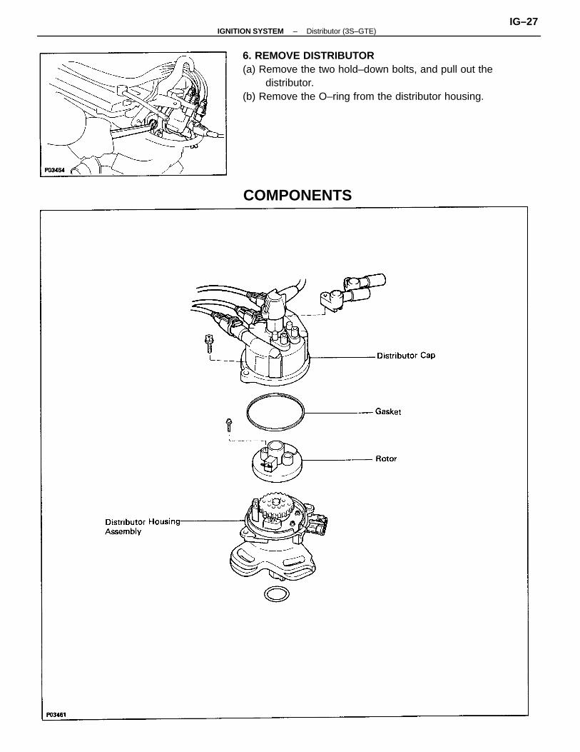
6. REMOVE DISTRIBUTOR(a) Remove the two hold–down bolts, and pull out the
distributor.(b) Remove the O–ring from the distributor housing.
COMPONENTS
–IGNITION SYSTEM Distributor (3S–GTE)IG–27
3. CONNECT HIGH–TENSION CORD TO IGNITION COIL4. CONNECT HIGH–TENSION CORDS TO SPARK PLUGS(a) Connect the four high–tension cords to the spark
plugs.Firing order: 1 – 3 – 4 – 2(b) Install the four high–tension cords to the cord
clamp.5. CONNECT DISTRIBUTOR CONNECTOR6. INSTALL INTERCOOLER(See steps 11 to 15 on page TC–17)7. CONNECT CABLE TO NEGATIVE TERMINAL OF
BATTERY8. WARM UP ENGINEAllow the engine to warm up to normal operating tempera-ture.
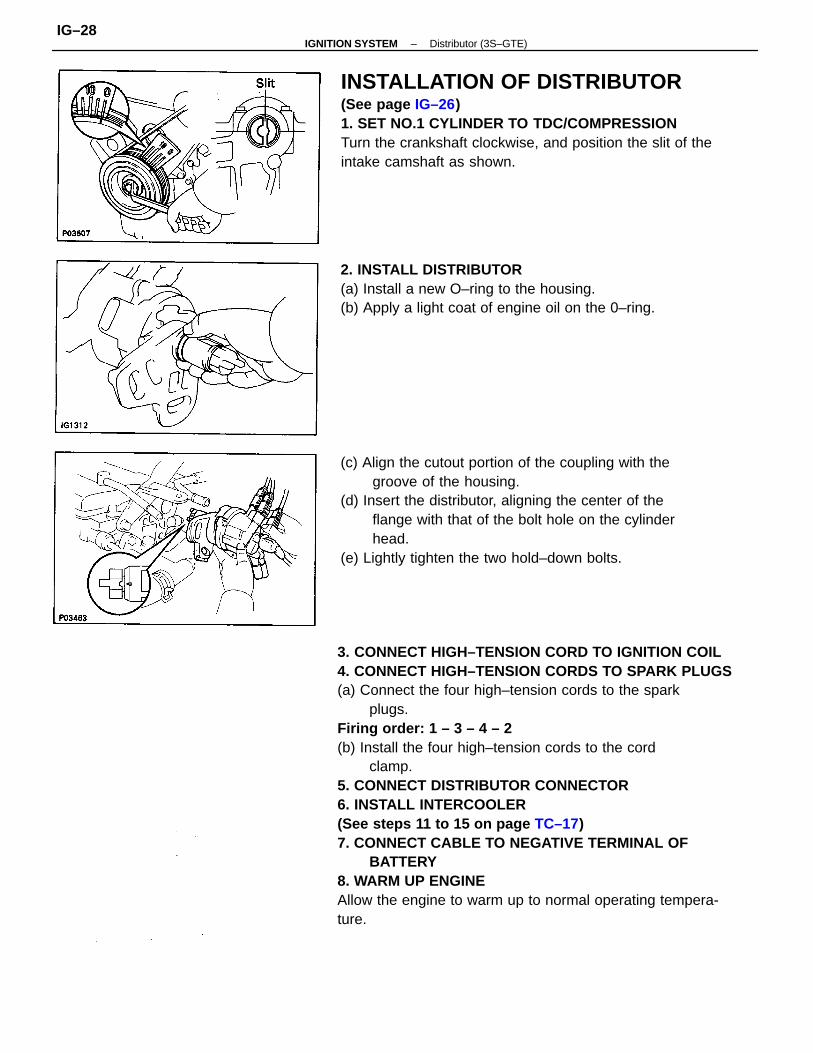
INSTALLATION OF DISTRIBUTOR(See page IG–26)1. SET NO.1 CYLINDER TO TDC/COMPRESSIONTurn the crankshaft clockwise, and position the slit of theintake camshaft as shown.
(c) Align the cutout portion of the coupling with thegroove of the housing.
(d) Insert the distributor, aligning the center of theflange with that of the bolt hole on the cylinderhead.
(e) Lightly tighten the two hold–down bolts.
2. INSTALL DISTRIBUTOR(a) Install a new O–ring to the housing.(b) Apply a light coat of engine oil on the 0–ring.
–IGNITION SYSTEM Distributor (3S–GTE)IG–28
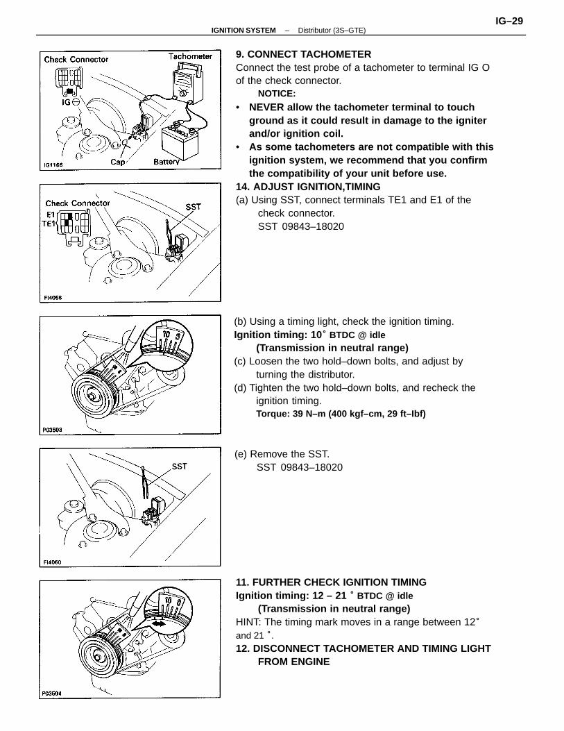
9. CONNECT TACHOMETERConnect the test probe of a tachometer to terminal IG Oof the check connector.
NOTICE:
• NEVER allow the tachometer terminal to touchground as it could result in damage to the igniterand/or ignition coil.
• As some tachometers are not compatible with thisignition system, we recommend that you confirmthe compatibility of your unit before use.
14. ADJUST IGNITION,TIMING(a) Using SST, connect terminals TE1 and E1 of the
check connector.SST 09843–18020
(b) Using a timing light, check the ignition timing.Ignition timing: 10 ° BTDC @ idle
(Transmission in neutral range)(c) Loosen the two hold–down bolts, and adjust by
turning the distributor.(d) Tighten the two hold–down bolts, and recheck the
ignition timing.Torque: 39 N–m (400 kgf–cm, 29 ft–Ibf)
11. FURTHER CHECK IGNITION TIMINGIgnition timing: 12 – 21 ° BTDC @ idle
(Transmission in neutral range)HINT: The timing mark moves in a range between 12°and 21 °.12. DISCONNECT TACHOMETER AND TIMING LIGHT
FROM ENGINE
(e) Remove the SST.SST 09843–18020
–IGNITION SYSTEM Distributor (3S–GTE)IG–29
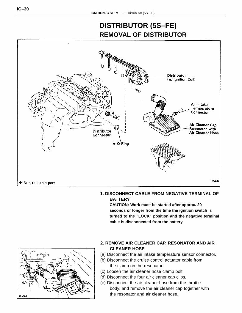
2. REMOVE AIR CLEANER CAP, RESONATOR AND AIRCLEANER HOSE
(a) Disconnect the air intake temperature sensor connector.(b) Disconnect the cruise control actuator cable from
the clamp on the resonator.(c) Loosen the air cleaner hose clamp bolt.(d) Disconnect the four air cleaner cap clips.(e) Disconnect the air cleaner hose from the throttle
body, and remove the air cleaner cap together withthe resonator and air cleaner hose.
1. DISCONNECT CABLE FROM NEGATIVE TERMINAL OFBATTERYCAUTION: Work must be started after approx. 20seconds or longer from the time the ignition switch isturned to the ”LOCK” position and the negative terminalcable is disconnected from the battery.
DISTRIBUTOR (5S–FE)REMOVAL OF DISTRIBUTOR
–IGNITION SYSTEM Distributor (5S–FE)IG–30
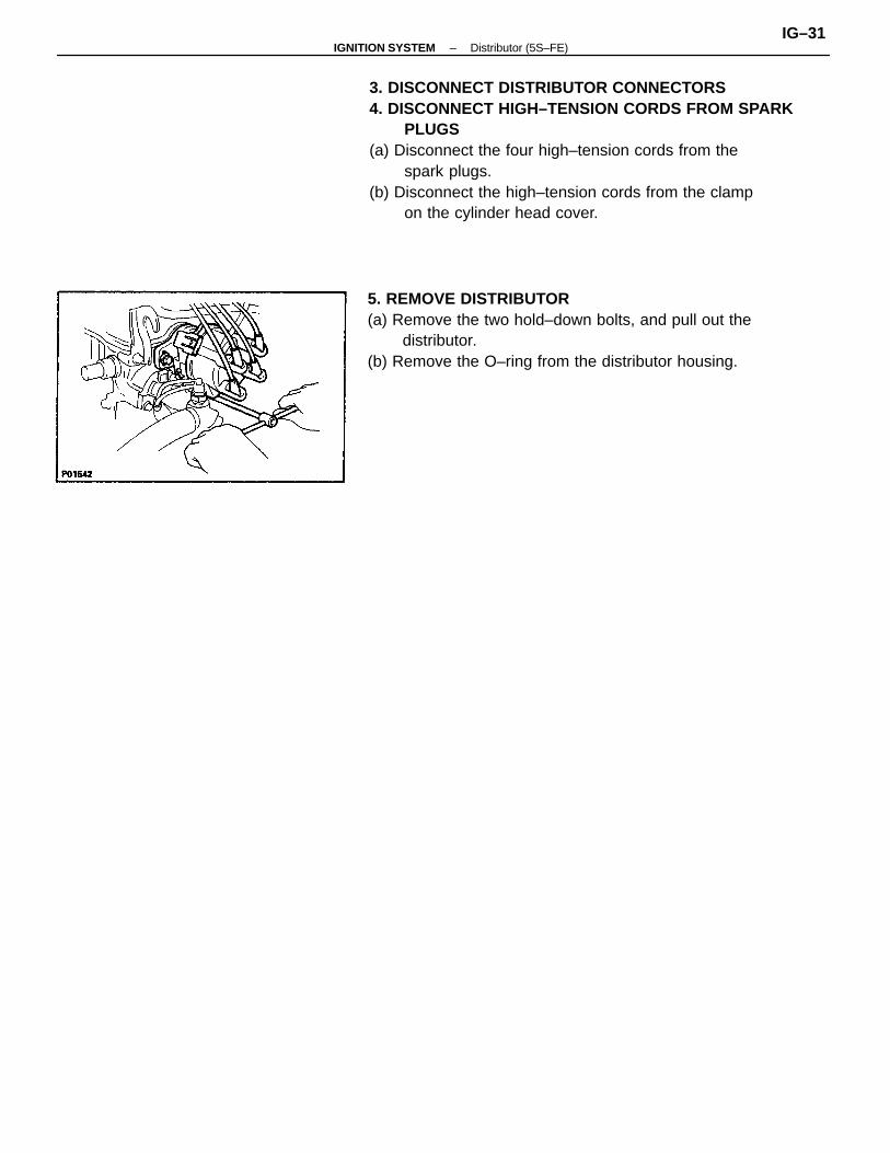
3. DISCONNECT DISTRIBUTOR CONNECTORS4. DISCONNECT HIGH–TENSION CORDS FROM SPARK
PLUGS(a) Disconnect the four high–tension cords from the
spark plugs.(b) Disconnect the high–tension cords from the clamp
on the cylinder head cover.
5. REMOVE DISTRIBUTOR(a) Remove the two hold–down bolts, and pull out the
distributor.(b) Remove the O–ring from the distributor housing.
–IGNITION SYSTEM Distributor (5S–FE)IG–31
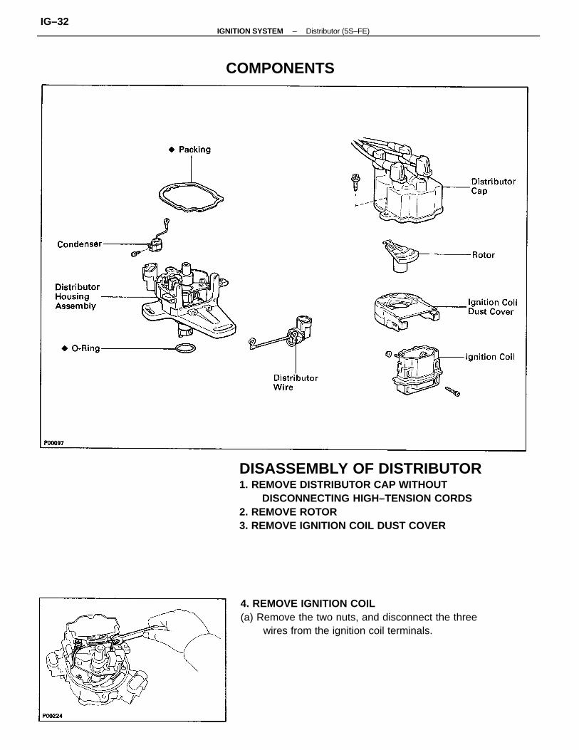
DISASSEMBLY OF DISTRIBUTOR1. REMOVE DISTRIBUTOR CAP WITHOUT
DISCONNECTING HIGH–TENSION CORDS2. REMOVE ROTOR3. REMOVE IGNITION COIL DUST COVER
4. REMOVE IGNITION COIL(a) Remove the two nuts, and disconnect the three
wires from the ignition coil terminals.
COMPONENTS
–IGNITION SYSTEM Distributor (5S–FE)IG–32
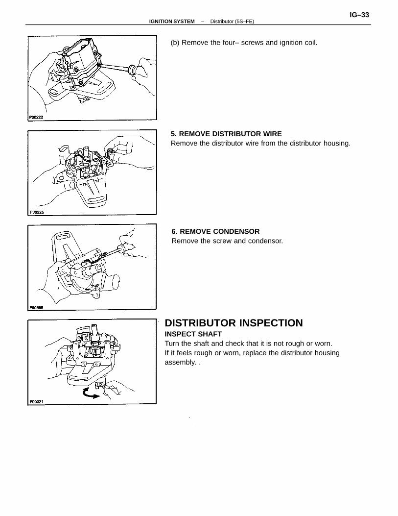
DISTRIBUTOR INSPECTIONINSPECT SHAFTTurn the shaft and check that it is not rough or worn.If it feels rough or worn, replace the distributor housingassembly. .
5. REMOVE DISTRIBUTOR WIRERemove the distributor wire from the distributor housing.
6. REMOVE CONDENSORRemove the screw and condensor.
(b) Remove the four– screws and ignition coil.
–IGNITION SYSTEM Distributor (5S–FE)IG–33
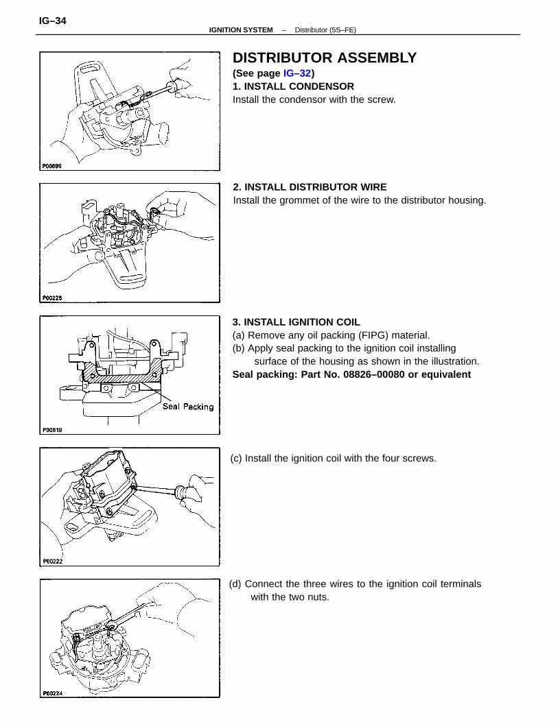
3. INSTALL IGNITION COIL(a) Remove any oil packing (FIPG) material.(b) Apply seal packing to the ignition coil installing
surface of the housing as shown in the illustration.Seal packing: Part No. 08826–00080 or equivalent
DISTRIBUTOR ASSEMBLY(See page IG–32)1. INSTALL CONDENSORInstall the condensor with the screw.
2. INSTALL DISTRIBUTOR WIREInstall the grommet of the wire to the distributor housing.
(d) Connect the three wires to the ignition coil terminalswith the two nuts.
(c) Install the ignition coil with the four screws.
–IGNITION SYSTEM Distributor (5S–FE)IG–34
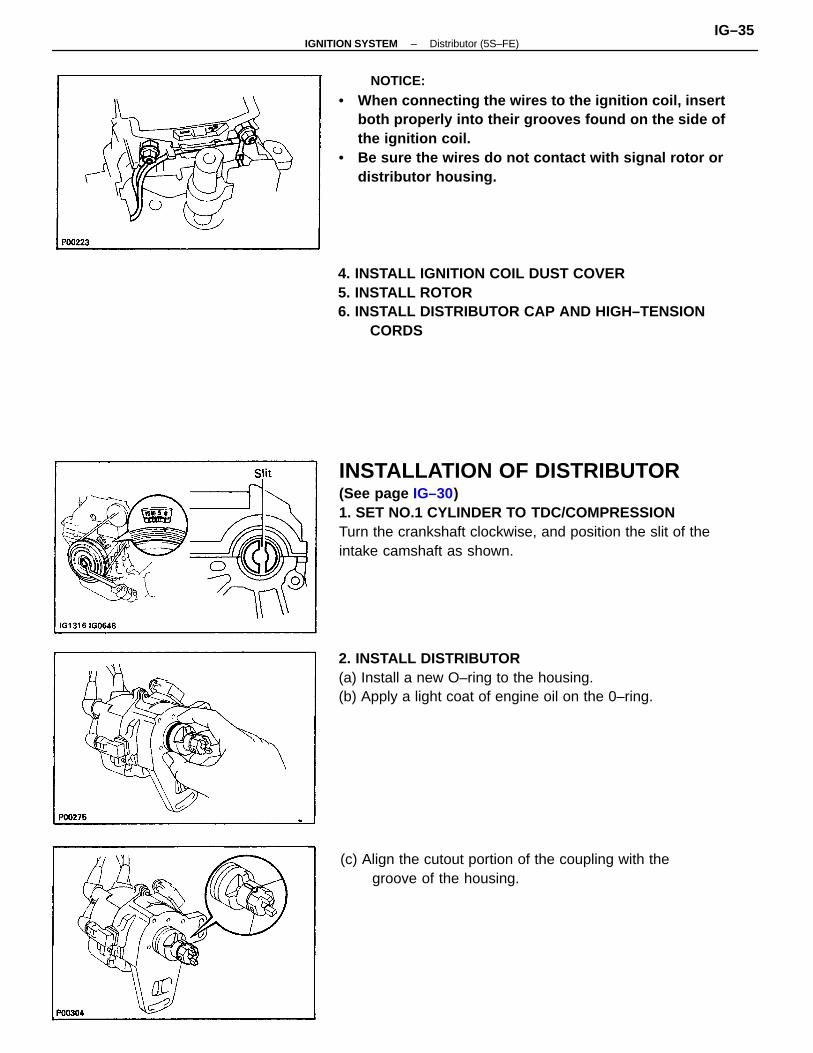
INSTALLATION OF DISTRIBUTOR(See page IG–30)1. SET NO.1 CYLINDER TO TDC/COMPRESSIONTurn the crankshaft clockwise, and position the slit of theintake camshaft as shown.
NOTICE:
• When connecting the wires to the ignition coil, insertboth properly into their grooves found on the side ofthe ignition coil.
• Be sure the wires do not contact with signal rotor ordistributor housing.
4. INSTALL IGNITION COIL DUST COVER5. INSTALL ROTOR6. INSTALL DISTRIBUTOR CAP AND HIGH–TENSION
CORDS
2. INSTALL DISTRIBUTOR(a) Install a new O–ring to the housing.(b) Apply a light coat of engine oil on the 0–ring.
(c) Align the cutout portion of the coupling with thegroove of the housing.
–IGNITION SYSTEM Distributor (5S–FE)IG–35
8. CONNECT TACHOMETERConnect the test probe of a tachometer to terminal IG EDof the check connector.
NOTICE:
• NEVER allow the tachometer terminal to touchground as it could result in damage to the igniterand/or ignition coil.
• As some tachometers are not compatible with thisignition system, we recommend that you confirmthe compatibility of your unit before use.
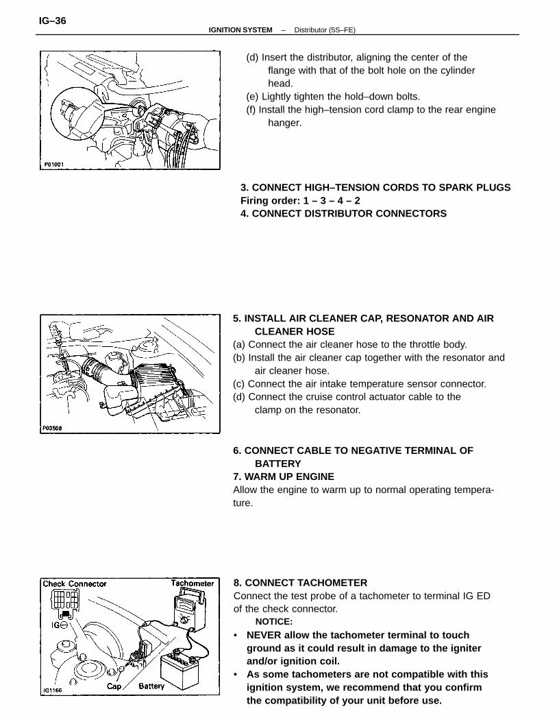
5. INSTALL AIR CLEANER CAP, RESONATOR AND AIRCLEANER HOSE
(a) Connect the air cleaner hose to the throttle body.(b) Install the air cleaner cap together with the resonator and
air cleaner hose.(c) Connect the air intake temperature sensor connector.(d) Connect the cruise control actuator cable to the
clamp on the resonator.
(d) Insert the distributor, aligning the center of theflange with that of the bolt hole on the cylinderhead.
(e) Lightly tighten the hold–down bolts.(f) Install the high–tension cord clamp to the rear engine
hanger.
6. CONNECT CABLE TO NEGATIVE TERMINAL OFBATTERY
7. WARM UP ENGINEAllow the engine to warm up to normal operating tempera-ture.
3. CONNECT HIGH–TENSION CORDS TO SPARK PLUGSFiring order: 1 – 3 – 4 – 24. CONNECT DISTRIBUTOR CONNECTORS
–IGNITION SYSTEM Distributor (5S–FE)IG–36
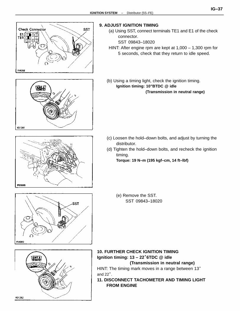
10. FURTHER CHECK IGNITION TIMINGIgnition timing: 13 – 22 °6TDC @ idle
(Transmission in neutral range)HINT: The timing mark moves in a range between 13°and 22°.11. DISCONNECT TACHOMETER AND TIMING LIGHT
FROM ENGINE
9. ADJUST IGNITION TIMING(a) Using SST, connect terminals TE1 and E1 of the check
connector.SST 09843–18020
HINT: After engine rpm are kept at 1,000 – 1,300 rpm for5 seconds, check that they return to idle speed.
(c) Loosen the hold–down bolts, and adjust by turning thedistributor.
(d) Tighten the hold–down bolts, and recheck the ignitiontiming.Torque: 19 N–m (195 kgf–cm, 14 ft–lbf)
(b) Using a timing light, check the ignition timing.Ignition timing: 10”BTDC @ idle
(Transmission in neutral range)
(e) Remove the SST.SST 09843–18020
–IGNITION SYSTEM Distributor (5S–FE)IG–37