Embed Size (px)
Citation preview
IFS MC251-4P/1S and NS2051-4P/1T User Manual
P/N 1072572 • REV 00.06 • ISS 30JAN13
ii IFS MC251-4P/1S and NS2051-4P/1T User Manual
Copyright © 2013 UTC Fire & Security Americas Corporation, Inc.
Interlogix is part of UTC Climate Controls & Security, a unit of United Technologies Corporation. All rights reserved.
Trademarks andpatents
The IFS MC251-4P/1S and NS2051-4P/1T and logo are trademarks of United Technologies. Other trade names used in this document may be trademarks or registered trademarks of the manufacturers or vendors of the respective products.
Intended use Use this product only for the purpose it was designed for; refer to the data sheet and user documentation for details. For the latest product information, contact your local supplier or visit us online at www.interlogix.com.
Manufacturer UTC Fire & Security Americas Corporation, Inc. 2955 Red Hill Avenue Costa Mesa, CA 92626-5923, USA EU authorized manufacturing representative: UTC Fire & Security B.V., Kelvinstraat 7, 6003 DH Weert, The Netherlands
Certification N4131
FCC compliance This equipment has been tested and found to comply with the limits for a Class A digital device, pursuant to part 15 of the FCC Rules. These limits are designed to provide reasonable protection against harmful interference when the equipment is operated in a commercial environment. This equipment generates, uses, and can radiate radio frequency energy and, if not installed and used in accordance with the instruction manual, may cause harmful interference to radio communications. You are cautioned that any changes or modifications not expressly approved by the party responsible for compliance could void the user's authority to operate the equipment.
ACMA compliance Notice! This is a Class A product. In a domestic environment this product may cause radio interference in which case the user may be required to take adequate measures.
Canada This Class A digital apparatus complies with Canadian ICES-003.Cet appareil numérique de la classe A est conforme á la norme NMB-003du Canada.
European Union directives
2004/108/EC (EMC Directive): Hereby, UTC Fire & Security Americas Corporation, Inc. declares that this device is in compliance with the essential requirements and other relevant provisions of Directive 2004/108/EC.
2002/96/EC (WEEE directive): Products marked with this symbol cannot be disposed of as unsorted municipal waste in the European Union. For proper recycling, return this product to your local supplier upon the purchase of equivalent new equipment, or dispose of it at designated collection points. For more information see: www.recyclethis.info.
Contact information For contact information see our Web site: www.interlogix.com.
Contact support www.interlogix.com/customer support
IFS MC251-4P/1S and NS2051-4P/1T User Manual iii
Contents
Overview 1 Package Contents 1 Product Features 2
Installation 4 Product Description 4 Front Panel 5 LED Indicators 6 Top Panel 7 Wiring the Power Inputs 7 Wiring the Fault Alarm Contact 8 Mounting Installation 9
Application 13 Installation Steps 13
Switch Operation 14
Troubleshooting 17
Specifications 18 RJ45 Pin Assignments 21
Contacting Technical Support 23

IFS MC251-4P/1S and NS2051-4P/1T User Manual 1
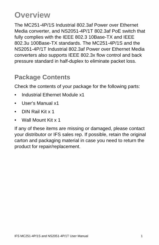
Overview The MC251-4P/1S Industrial 802.3af Power over Ethernet Media converter, and NS2051-4P/1T 802.3af PoE switch that fully complies with the IEEE 802.3 10Base-TX and IEEE 802.3u 100Base-TX standards. The MC251-4P/1S and the NS2051-4P/1T Industrial 802.3af Power over Ethernet Media converters also supports IEEE 802.3x flow control and back pressure standard in half-duplex to eliminate packet loss.
Package Contents Check the contents of your package for the following parts:
• Industrial Ethernet Module x1
• User’s Manual x1
• DIN Rail Kit x 1
• Wall Mount Kit x 1
If any of these items are missing or damaged, please contact your distributor or IFS sales rep. If possible, retain the original carton and packaging material in case you need to return the product for repair/replacement.
2 IFS MC251-4P/1S and NS2051-4P/1T User Manual
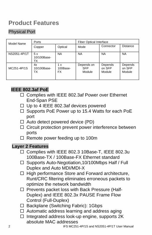
Product Features Physical Port
Ports Fiber Optical Interface Model Name Copper Optical Mode Connector Distance
NS2051-4P/1T 5 x 10/100Base-TX
NA NA NA NA
MC251-4P/1S
4x 10/100Base-TX
1 x 100Base-FX
Depends on SFP Module
Depends on SFP Module
Depends on SFP Module
IEEE 802.3af PoE Complies with IEEE 802.3af Power over Ethernet
End-Span PSE Up to 4 IEEE 802.3af devices powered Supports PoE Power up to 15.4 Watts for each PoE
port Auto detect powered device (PD) Circuit protection prevent power interference between
ports Remote power feeding up to 100m
Layer 2 Features Complies with IEEE 802.3 10Base-T, IEEE 802.3u
100Base-TX / 100Base-FX Ethernet standard Supports Auto-Negotiation,10/100Mbps Half / Full
Duplex and Auto MDI/MDI-X High performance Store and Forward architecture,
Runt/CRC filtering eliminates erroneous packets to optimize the network bandwidth
Prevents packet loss with Back Pressure (Half-Duplex) and IEEE 802.3x PAUSE Frame Flow Control (Full-Duplex)
Backplane (Switching Fabric): 1Gbps Automatic address learning and address aging Integrated address look-up engine, supports 2K
absolute MAC addresses
IFS MC251-4P/1S and NS2051-4P/1T User Manual 3
CSMA/CD Protocol
Industrial Case / Installation IP-30 Aluminum Metal case / Protection DIN Rail and Wall Mount Design Redundant Power Design: 24 or 48V DC, redundant
power with polarity reverse protect function Supports EFT protection 6000V DC for power line Supports 6000V DC Ethernet ESD protection -40 to 75 Degree C operating temperature
4 IFS MC251-4P/1S and NS2051-4P/1T User Manual
Installation This section describes the functionalities of the Industrial Fast Ethernet components and guides how to install it on the desktop. Basic knowledge of networking is assumed. Please read this chapter completely before installation.
In the following section, the term “Industrial Fast Ethernet Switch” means the MC251-4P/1S and the NS2051-4P/1T
Product Description The IFS MC251-4P/1S and the NS2051-4P/1T are 5-Port 10/100Mbps with 4-Port PoE unmanaged Industrial Fast Ethernet Switches and provide non-blocking wire-speed performance in an IP-30 aluminum metal enclosure for easy deployment in harsh Industrial demanding environments.
The PoE in-line power follow the standard IEEE 802.3af and allows to power 4 PoE compliant devices at distance of up to 100 meters through the 4-pair Cat 5 / 5e UTP wire. With Data and Power over Ethernet from one unit, the MC251-4P/1S and the NS2051-4P/1T reduces cable deployment and eliminates the need for dedicated electrical outlets on the wall, ceiling or any hard to reach locations.
With 1Gbps internal switching fabric, the Industrial Fast Ethernet Switch can handle large amounts of data in a secure topology linking to a backbone or high capacity servers.
The Industrial Fast Ethernet Switch has a 2K MAC address table and offers wire-speed packets transfer performance without risk of packet loss. The stable throughput of the device makes it ideal for most Ethernet environments.
All RJ-45 copper interfaces support 10/100Mbps Auto-negotiation for optimal speed detection through RJ-45 Category 3, 4, 5, 5e or 6 cables. Support standard for Auto-MDI/MDI-X that can detect the type of connection to any
IFS MC251-4P/1S and NS2051-4P/1T User Manual 5
Ethernet device without requiring special straight or crossover cables.
The Flow Control function allows Industrial Fast Ethernet Switch supported routers and servers to directly connect to this device for fast, reliable data transfer.
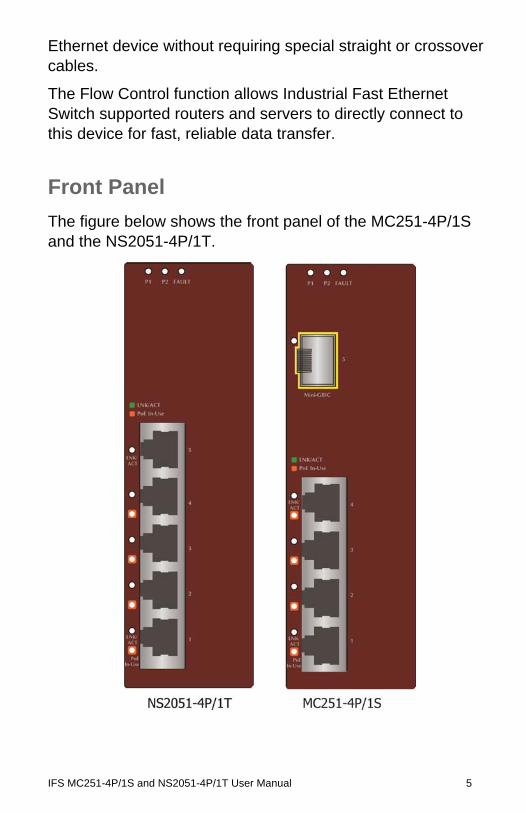
Front Panel
The figure below shows the front panel of the MC251-4P/1S and the NS2051-4P/1T.
6 IFS MC251-4P/1S and NS2051-4P/1T User Manual
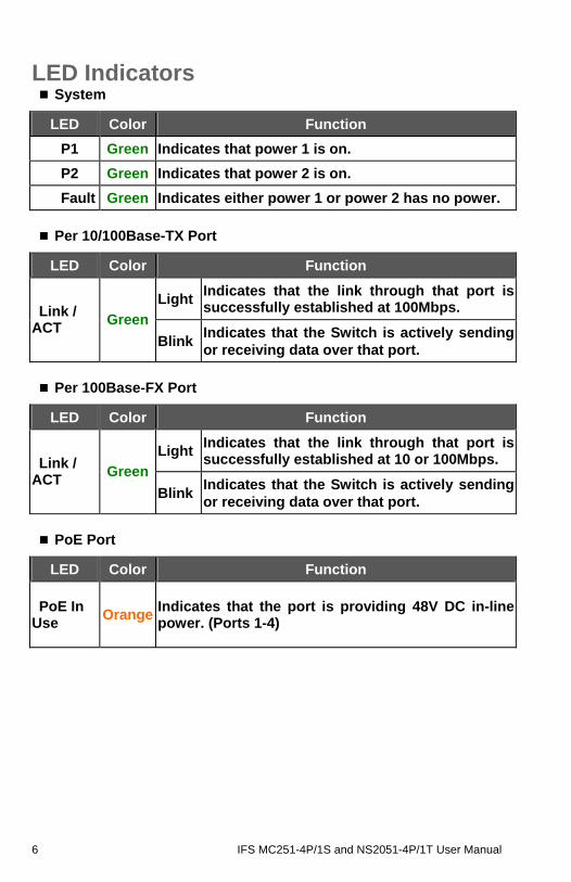
LED Indicators System
LED Color Function
P1 Green Indicates that power 1 is on.
P2 Green Indicates that power 2 is on.
Fault Green Indicates either power 1 or power 2 has no power.
Per 10/100Base-TX Port
LED Color Function
LightIndicates that the link through that port is successfully established at 100Mbps. Link /
ACT Green
BlinkIndicates that the Switch is actively sending or receiving data over that port.
Per 100Base-FX Port
LED Color Function
LightIndicates that the link through that port is successfully established at 10 or 100Mbps. Link /
ACT Green
BlinkIndicates that the Switch is actively sending or receiving data over that port.
PoE Port
LED Color Function
PoE In Use
Orange Indicates that the port is providing 48V DC in-line power. (Ports 1-4)
IFS MC251-4P/1S and NS2051-4P/1T User Manual 7
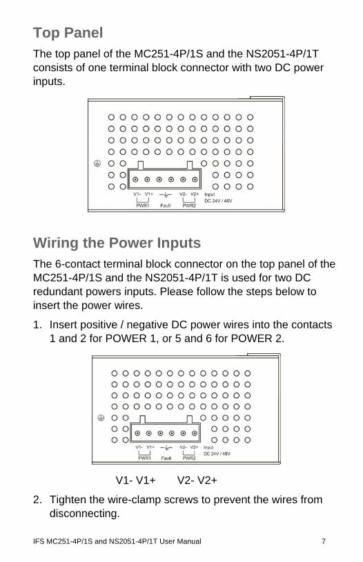
Top Panel The top panel of the MC251-4P/1S and the NS2051-4P/1T consists of one terminal block connector with two DC power inputs.
Wiring the Power Inputs The 6-contact terminal block connector on the top panel of the MC251-4P/1S and the NS2051-4P/1T is used for two DC redundant powers inputs. Please follow the steps below to insert the power wires.
1. Insert positive / negative DC power wires into the contacts 1 and 2 for POWER 1, or 5 and 6 for POWER 2.
V1- V1+ V2- V2+
2. Tighten the wire-clamp screws to prevent the wires from disconnecting.
8 IFS MC251-4P/1S and NS2051-4P/1T User Manual
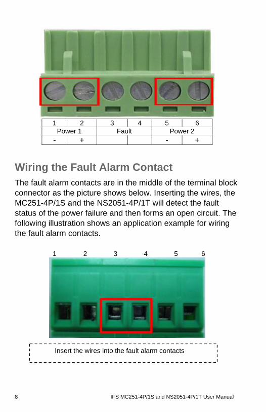
1 2 3 4 5 6
Power 1 Fault Power 2 - + - +
Wiring the Fault Alarm Contact The fault alarm contacts are in the middle of the terminal block connector as the picture shows below. Inserting the wires, the MC251-4P/1S and the NS2051-4P/1T will detect the fault status of the power failure and then forms an open circuit. The following illustration shows an application example for wiring the fault alarm contacts.
1 2 3 4 5 6
Insert the wires into the fault alarm contacts
IFS MC251-4P/1S and NS2051-4P/1T User Manual 9
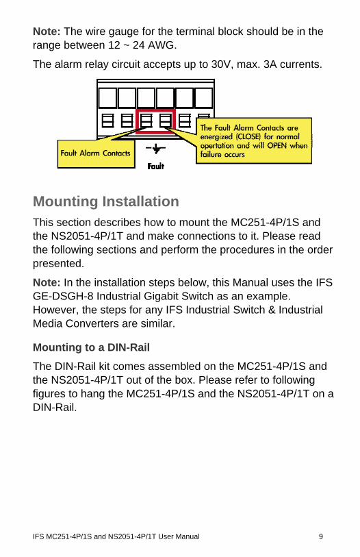
Note: The wire gauge for the terminal block should be in the range between 12 ~ 24 AWG.
The alarm relay circuit accepts up to 30V, max. 3A currents.
Mounting Installation This section describes how to mount the MC251-4P/1S and the NS2051-4P/1T and make connections to it. Please read the following sections and perform the procedures in the order presented.
Note: In the installation steps below, this Manual uses the IFS GE-DSGH-8 Industrial Gigabit Switch as an example. However, the steps for any IFS Industrial Switch & Industrial Media Converters are similar.
Mounting to a DIN-Rail
The DIN-Rail kit comes assembled on the MC251-4P/1S and the NS2051-4P/1T out of the box. Please refer to following figures to hang the MC251-4P/1S and the NS2051-4P/1T on a DIN-Rail.
10 IFS MC251-4P/1S and NS2051-4P/1T User Manual
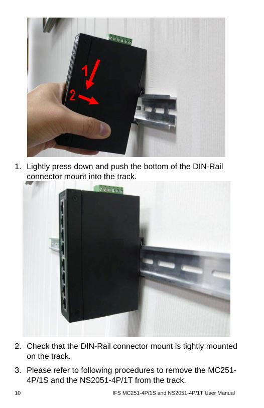
1. Lightly press down and push the bottom of the DIN-Rail connector mount into the track.
2. Check that the DIN-Rail connector mount is tightly mounted on the track.
3. Please refer to following procedures to remove the MC251-4P/1S and the NS2051-4P/1T from the track.
IFS MC251-4P/1S and NS2051-4P/1T User Manual 11
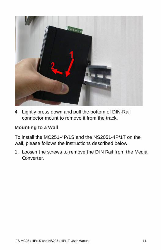
4. Lightly press down and pull the bottom of DIN-Rail connector mount to remove it from the track.
Mounting to a Wall
To install the MC251-4P/1S and the NS2051-4P/1T on the wall, please follows the instructions described below.
1. Loosen the screws to remove the DIN Rail from the Media Converter.
12 IFS MC251-4P/1S and NS2051-4P/1T User Manual
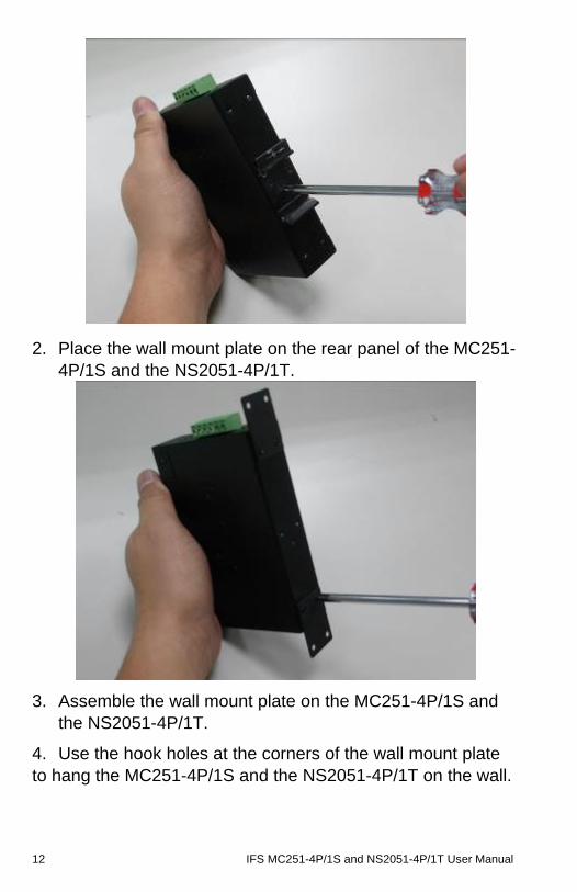
2. Place the wall mount plate on the rear panel of the MC251-4P/1S and the NS2051-4P/1T.
3. Assemble the wall mount plate on the MC251-4P/1S and the NS2051-4P/1T.
4. Use the hook holes at the corners of the wall mount plate to hang the MC251-4P/1S and the NS2051-4P/1T on the wall.
IFS MC251-4P/1S and NS2051-4P/1T User Manual 13
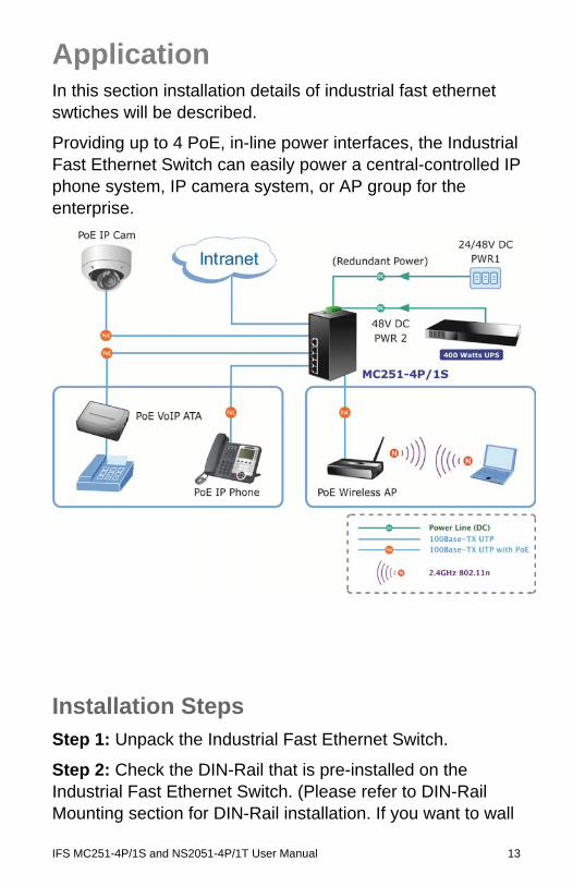
Application In this section installation details of industrial fast ethernet swtiches will be described.
Providing up to 4 PoE, in-line power interfaces, the Industrial Fast Ethernet Switch can easily power a central-controlled IP phone system, IP camera system, or AP group for the enterprise.
Installation Steps Step 1: Unpack the Industrial Fast Ethernet Switch.
Step 2: Check the DIN-Rail that is pre-installed on the Industrial Fast Ethernet Switch. (Please refer to DIN-Rail Mounting section for DIN-Rail installation. If you want to wall
14 IFS MC251-4P/1S and NS2051-4P/1T User Manual
mount the Industrial Fast Ethernet Switch, then please refer to Wall Mount Plate Mounting section for specific instructions.
Step 3: To hang the Industrial Fast Ethernet Switch on the DIN-Rail track or wall, please refer to the Mounting Installation section.
Step 4: Power on the Industrial Fast Ethernet Switch. (Please refer to the Wiring the Power Inputs section for power input) The power LED on the Industrial Fast Ethernet Switch will illuminate. Please refer to the LED Indicators section for meaning of LED lights.
Step 5: Prepare the twisted-pair, straight through Category 5 cable for Ethernet connection.
Step 6: Insert one side of Category 5 cables into the Industrial Fast Ethernet Switch Ethernet port (RJ-45 port) and the other side to the network device Ethernet port (RJ-45 port), ex: Switch, PC or Server. The UTP port (RJ-45) LED on the Industrial Fast Ethernet Switch will light up when the cable is connected to the network device. Please refer to the LED Indicators section for LED light meaning.
Step 7: Insert fiber cable from the MC251-4P/1S to the fiber network. TX, RX must be paired at both ends. The optical port LED on the MC251-4P/1S will illuminate when the connection is established with network device. Please refer to the LED Indicators section for LED light meaning.
Step 8: When all connections are set up and the LEDs illuminate, the installation is completed.
Switch Operation Address Table
The Industrial Fast Ethernet Switch is implemented with an address table. This address table is composed of many entries. Each entry is used to store the address information of
IFS MC251-4P/1S and NS2051-4P/1T User Manual 15
each node in the network, including MAC address, Port No., etc. This information comes from the learning process of the Industrial Fast Ethernet Switch.
Learning
When one packet comes from any port of the Industrial Fast Ethernet switch, the Industrial Fast Ethernet Switch will record the source address, port no. and other related information in the address table. This information will be used to decide either forwarding or filtering for future packets.
Forwarding & Filtering
When one packet comes from another port of the Industrial Fast Ethernet Switch, it will also check the destination address besides the source address learning. The Industrial Fast Ethernet Switch will lookup the address-table for the destination address. If not found, this packet will be forwarded to all the other ports except the port which this packet came in. And these ports will transmit this packet to the network it's connected to. If found, and the destination address is located at a different port from this packet comes in, the Industrial Fast Ethernet Switch will forward this packet to the port where this destination address is located according to the information from address table. But, if the destination address is located at the same port with this packet comes in, then this packet will be filtered.
Store-and-Forward
Store-and-Forward is one type of packet-forwarding techniques. A Store-and-Forward Industrial Switch stores the incoming frames in an internal buffer and checks for any errors from the frames before transmission. Lack of error packet occurrence is important for an efficient and stable network..
16 IFS MC251-4P/1S and NS2051-4P/1T User Manual
The Industrial Fast Ethernet Switch scans the destination address from the packet-header, searches the routing table provided for the incoming port and forwards the packet, only if required. The fast forwarding makes the switch attractive for connecting servers directly to the network, thereby increasing throughput and availability. However, the switch is most commonly used to segment existing hubs, which nearly always improves overall performance. Ethernet Switching can be easily configured in any Ethernet network environment to significantly boost bandwidth using conventional cabling and adapters.
Due to the learning function of the Industrial Fast Ethernet Switch, the source address and corresponding port number of each incoming and outgoing packet are stored in a routing table. This information is subsequently used to filter packets whose destination address is on the same segment as the source address. This confines network traffic to its respective domain, reducing the overall load on the network.
The Industrial Fast Ethernet Switch performs "Store-and-Forward" therefore, no error packets occur. More reliably, it reduces the re-transmission rate. No packet loss will occur.
Auto-negotiation
The TP ports on the Industrial Fast Ethernet Switch have built-in “Auto-negotiation”. This technology automatically sets the best possible bandwidth when a connection is established with another network device (usually at Power On or Reset). This is done by detecting the modes and speeds at the moment both devices are connected.
IFS MC251-4P/1S and NS2051-4P/1T User Manual 17
Troubleshooting This chapter contains information to help resolving issues. If the Industrial Fast Ethernet Switch is not functioning properly, make sure the device was set up according to instructions in this manual.
The Link LED is not light
Solution:
Check the cable connection of the Industrial Fast Ethernet Switch.
Performance is bad
Solution:
Check the speed duplex mode of the partner device. The Industrial Fast Ethernet Switch is operating at Auto-negotiation mode by default and if the partner is set to half duplex, then the performance will become bad.
Link LED is illuminated but the traffic is irregular
Solution:
Check that the attached device is not set to dedicate full duplex. Some devices use a physical or software switch to change duplex modes. Auto-negotiation may not recognize this type of full-duplex setting.
Why does the Industrial Fast Ethernet Switch not connect to the network?
Solution:
Check every port LED on the Industrial Fast Ethernet Switch.
Try another port on the Industrial Fast Ethernet Switch to make sure the cable is installed properly while making sure the cable is the right type
Turn off the power and turn on the power again after waiting for awhile.
18 IFS MC251-4P/1S and NS2051-4P/1T User Manual
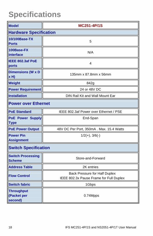
Specifications Model MC251-4P/1S
Hardware Specification
10/100Base-TX Ports
5
100Base-FX interface
N/A
IEEE 802.3af PoE ports
4
Dimensions (W x D x H)
135mm x 87.8mm x 56mm
Weight 842g
Power Requirement 24 or 48V DC
Installation DIN Rail Kit and Wall Mount Ear
Power over Ethernet
PoE Standard IEEE 802.3af Power over Ethernet / PSE
PoE Power Supply Type
End-Span
PoE Power Output 48V DC Per Port, 350mA . Max. 15.4 Watts
Power Pin Assignment
1/2(+), 3/6(-)
Switch Specification
Switch Processing Scheme
Store-and-Forward
Address Table 2K entries
Flow Control Back Pressure for Half Duplex
IEEE 802.3x Pause Frame for Full Duplex
Switch fabric 1Gbps
Throughput (Packet per second)
0.74Mpps
IFS MC251-4P/1S and NS2051-4P/1T User Manual 19
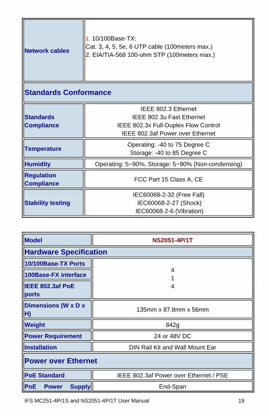
Network cables
1. 10/100Base-TX: Cat. 3, 4, 5, 5e, 6 UTP cable (100meters max.) 2. EIA/TIA-568 100-ohm STP (100meters max.)
Standards Conformance
Standards Compliance
IEEE 802.3 Ethernet IEEE 802.3u Fast Ethernet
IEEE 802.3x Full-Duplex Flow Control IEEE 802.3af Power over Ethernet
Temperature Operating: -40 to 75 Degree C Storage: -40 to 85 Degree C
Humidity Operating: 5~90%, Storage: 5~90% (Non-condensing)
Regulation Compliance
FCC Part 15 Class A, CE
Stability testing IEC60068-2-32 (Free Fall) IEC60068-2-27 (Shock)
IEC60068-2-6 (Vibration)
Model NS2051-4P/1T
Hardware Specification
10/100Base-TX Ports
100Base-FX interface
IEEE 802.3af PoE ports
4 1 4
Dimensions (W x D x H)
135mm x 87.8mm x 56mm
Weight 842g
Power Requirement 24 or 48V DC
Installation DIN Rail Kit and Wall Mount Ear
Power over Ethernet
PoE Standard IEEE 802.3af Power over Ethernet / PSE
PoE Power Supply End-Span
20 IFS MC251-4P/1S and NS2051-4P/1T User Manual
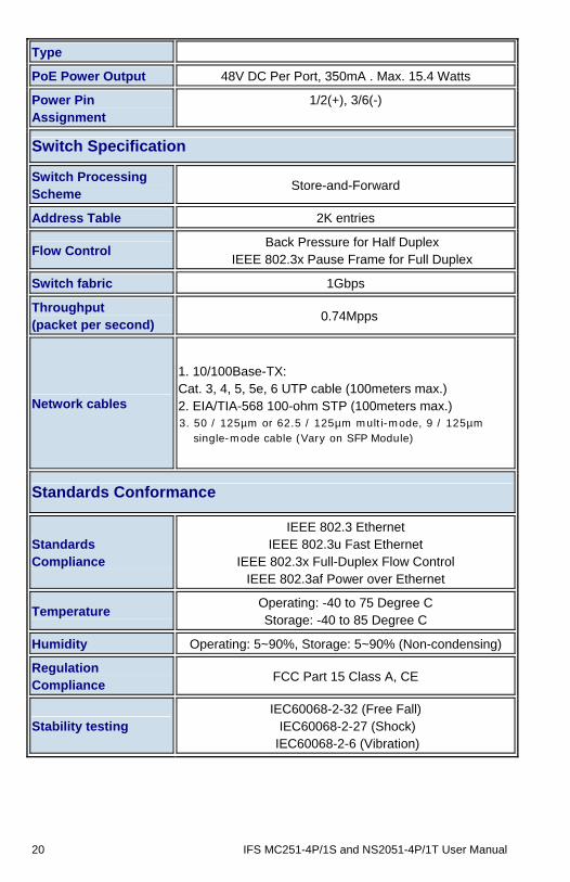
Type
PoE Power Output 48V DC Per Port, 350mA . Max. 15.4 Watts
Power Pin Assignment
1/2(+), 3/6(-)
Switch Specification
Switch Processing Scheme
Store-and-Forward
Address Table 2K entries
Flow Control Back Pressure for Half Duplex
IEEE 802.3x Pause Frame for Full Duplex
Switch fabric 1Gbps
Throughput (packet per second)
0.74Mpps
Network cables
1. 10/100Base-TX: Cat. 3, 4, 5, 5e, 6 UTP cable (100meters max.) 2. EIA/TIA-568 100-ohm STP (100meters max.) 3. 50 / 125µm or 62.5 / 125µm multi-mode, 9 / 125µm
single-mode cable (Vary on SFP Module)
Standards Conformance
Standards Compliance
IEEE 802.3 Ethernet IEEE 802.3u Fast Ethernet
IEEE 802.3x Full-Duplex Flow Control IEEE 802.3af Power over Ethernet
Temperature Operating: -40 to 75 Degree C Storage: -40 to 85 Degree C
Humidity Operating: 5~90%, Storage: 5~90% (Non-condensing)
Regulation Compliance
FCC Part 15 Class A, CE
Stability testing IEC60068-2-32 (Free Fall) IEC60068-2-27 (Shock)
IEC60068-2-6 (Vibration)
IFS MC251-4P/1S and NS2051-4P/1T User Manual 21
When connecting to other Ethernet equipment such as a Router, Bridge, Switch, or Hub, please refer to that device’s Technical Manual.
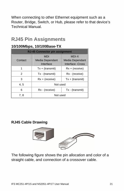
RJ45 Pin Assignments 10/100Mbps, 10/100Base-TX
RJ-45 Connector pin assignment
Contact MDI
Media Dependant Interface
MDI-X Media Dependant Interface -Cross
1 Tx + (transmit) Rx + (receive)
2 Tx - (transmit) Rx - (receive)
3 Rx + (receive) Tx + (transmit)
4, 5 Not used
6 Rx - (receive) Tx - (transmit)
7, 8 Not used
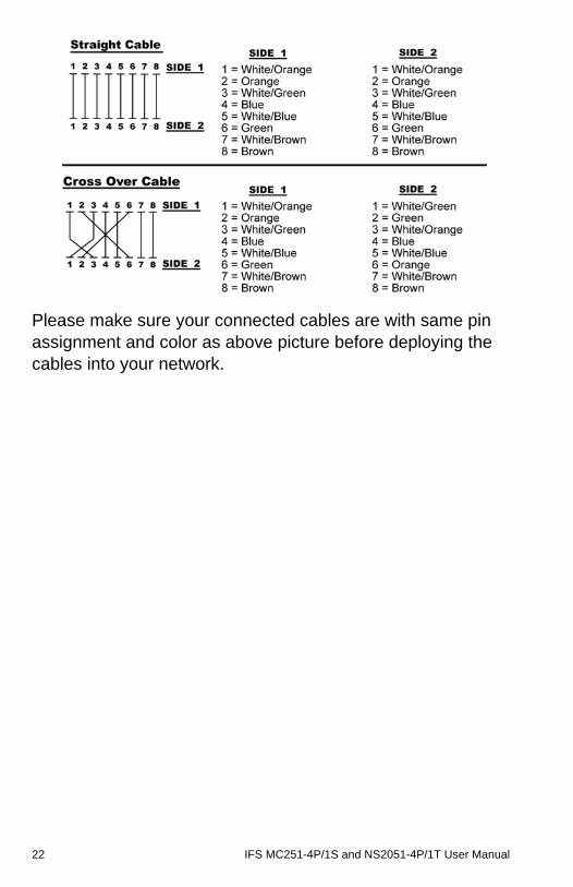
RJ45 Cable Drawing
The following figure shows the pin allocation and color of a straight cable, and connection of a crossover cable.
22 IFS MC251-4P/1S and NS2051-4P/1T User Manual
Please make sure your connected cables are with same pin assignment and color as above picture before deploying the cables into your network.
IFS MC251-4P/1S and NS2051-4P/1T User Manual 23
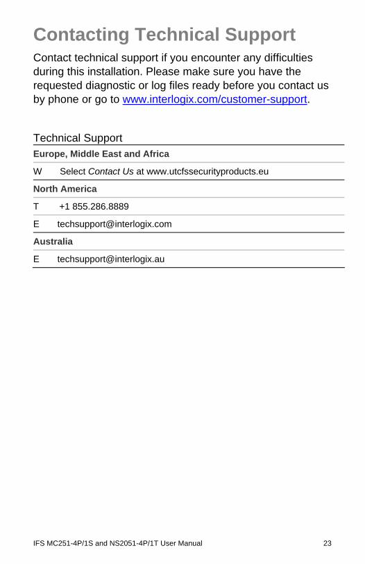
Contacting Technical Support Contact technical support if you encounter any difficulties during this installation. Please make sure you have the requested diagnostic or log files ready before you contact us by phone or go to www.interlogix.com/customer-support.
Technical Support Europe, Middle East and Africa
W Select Contact Us at www.utcfssecurityproducts.eu
North America
T +1 855.286.8889
Australia