Embed Size (px)
Citation preview

ABOVE GROUND POOL SAFETY
WARNINGFAILURE TO HEED THESE WARNINGS CAN RESULT IN PERMANENT INJURY,
PARALYSIS FROM A BROKEN NECK, ELECTROCUTION OR DROWNING.
THIS POOL IS NOT DESIGNED FOR DIVING OR JUMPING!DANGEROUS INJURY CAN RESULT, SHALLOW WATER!
Your pool contains a large quantity of water, and is deep enough to present inherent dangers to life and health unless the follow-ing safety rules are strictly observed. First-time users run the highest risk of injury. Make sure everyone understands. To insure your pool is used safely you must observe the following safety precautions:
1. NO JUMPING OR DIVING
The top rail of your pool is not a walkway and must not be used for jumping or diving.
Do not permit jumping or diving into the pool from a deck or the top rail of the pool. Diving or jumping into the pool can result in serious injury.
2. NEVER USE THE POOL ALONENever permit the pool to be used unless it is attended by at least one person other than the bather. Someone should always be available to lend assistance in an emergency.
3. NEVER LEAVE CHILDREN UNATTENDEDNever leave a child alone and unsupervised in or near the pool—not even for a second. There is no substitute for constant adult supervision.
4. NO ROUGH PLAYDo not permit “rough-playin” in and around your pool. Surfaces can become slippery and hazardous when wet.
5. LIGHT THE POOL AT NIGHTIf the pool is used after dusk, adequate lighting must be provided. Illumination in the pool area must be sufficient to clearly judge pool depth and all features in and around the pool. For light-ing recommendations, consult your local licensed electrical contractor
6. RESTRICT ACCESS TO THE POOLDo not leave chairs or other furniture beside the pool that could be used by a child to climb up into the pool. Ladders must be removed whenever the pool is unattended. A fence with a lockable gate around the pool or yard is strongly recommended and may be required by law in some jurisdictions.
7. NO ALCOHOL OR DRUGSNever drink alcoholic beverages or use any intoxicants which could hinder your judgment and reflexes.
8. KEEP YOUR POOL CLEAN AND SANITARYYour filter system will remove suspended particles from the water and the surface skimmer will remove insects, leaves and other debris from the water surface. Use the correct pool chemicals as directed to destroy harmful bacteria and prevent formation of algae. Remember, unsanitary water is a serious health hazard.
The safety stickers must be installed as per following instructions. Failure to properly install warning labels will void warranty. Failure to mount these safety labels may subject you to substantial liability in case of injury. These warning are not to be re-moved under any circumstances! If they become discolored or fall off please request replacements which will be sent at no charge.
FOLLOW ALL SAFETY INSTRUCTIONSRead and follow all safety instructions packaged with pool, ladder, deck or any other accessory. Additional pool safety publications can be obtained by contacting: The Association of Pool & Spa Professionals (www.apsp.org)
IMPORTANT NOTICE READ BEFORE INSTALLATION!
9.
KEEP OFF TOP LEDGESDo not walk on top ledges. They can be slippery and they are not a walkway.
10.
POOL COVER SAFETYThe cover must have a tamperproof locking retainer cable that positions the cover around the pool wall and keeps it securely in place.
Never allow anyone, especially small children on the cover. Asphyxiation or drowning could result. When purchasing any pool cover, please consult a swimming pool professional.
11. ELECTRICAL HAZARDNever touch or attempt to service electrical equipment, including the filter when your body and/or the ground is wet.
Electrocution or permanent injury due to high voltage (120V AC) could result. The pool should be bonded in accordance with Section 680-26 of the National Electical Code. For further assistance contact your dealer or a local licensed electrician. Do not use pool during electrical or rain storms.
12.
SAFETY ROPE & POLEKeep a safety rope 1/4" by 50" with a flotation buoy with an outside diamter of 15".
Have ac-cessible in a prominent area by your pool. Keep a pole not less that 16 feet (4,88m) long with a blunt or hook end available at pool side in case of emergencies.
13.
POOL CHEMICALSDo not place chlorine, chlorine tablets or sticks directly into skimmer, or winterize your pool with liquid chlorine.
Damage to the skimmer, pool liner and filter will result. Failure to obey this in-struction will void all component warranties. Always follow Chemical Manufacturer’s insturctions when storing, handling and dispensing pool chemicals.
14.
CHECK FOR DAMAGEPeriodically check your pool and ladder components for damage and wear.
Be sure all screws are in place. Replace all damaged or worn components and tighten all screws before you use the pool, deck or ladders. At first sign remove rust and touch up immediately.
15. POOL PARTSNever modify the pool or accessories, or remove or drill holes in the pool, deck or ladder com-ponents unless instructed.
Your pool wall is made of thin metal, there is an inherent cut hazard with metal so use gloves during installation. Always use Original Equipment Manufactured parts for your replacement parts.
REMEMBER
WATCH
CHILDREN
PLACE SIGN ON
LINER ABOVE WATER LINE, OPPOSITE ENTRY
TO POOL
PLACE SIGN ON
WALL NEXT TO POOL ENTRY
R.12/11
INSTRUCTIONS IFS STANDARD & DELUXE CONTOUR DECK AND SIDE DECK
P/N 95-0756

STEP 1: CHOOSE A PROPER LOCATION FOR THE DECK
When choosing the location of your deck on the pool please select a spot that is clear of obstacles such as over-head power lines, buried septic systems, property lines, areas with poor drainage, trees, sunlight and similar issues that may make the location of your deck un-safe or un-pleasant. The entry point to the deck must also be clearly visible from the house so that even when not in use you can watch over the area.
NORTH
SUMMER BREEZE SOUTH▼
↔
OVERHEADPOWERLINE
DISTANCETO FENCE
INGROUND DRAINAGE SYSTEM
►ENTRACE TOPOOL(VISIBLE FROM HOUSE)
POOL SAFETY SIGN
POOL SITE
POOLDECK
SampleBESTVIEW
▲
►◄EASTWEST
DECK
●●
SUN4 P.M.
PROPERTYLINE
FENCEHEIGHT
BLOCKVIEWFORPRIVACY
KITCHENWINDOW
FILTER &PUMP
SLIDING GLASS DOOR
SUNNOON
SUN2 P.M.
SUN10 A.M.
SUN8 A.M.
Use the “foot print” for your deck, located at the back of these instructions, to clearly mark out on the ground where your deck will go on the pool. Please do this carefully and accurately so that once the deck is being installed you are prepared for the exact location of the deck and the entrance to the deck. Refer to the footprint of your deck as needed throughout the installation.
STEP 2: SET THE PROPER LOCATION ON THE GROUND

STEP 3: BRACKETS INSTALLATION
NOTE: During the assembly of your deck you will be handling aluminum and stainless steel. These metals can have very sharp edges and corners. It is very important that you wear gloves at all times so that you do not cut or injure yourself.
Before you install the pool or the deck there are brackets that need to be attached to the uprights of the pool where the deck will be placed. These brackets and posts will secure the deck to the pool. There are 2 different bracket systems available, one for a metal upright and one for a resin upright. These brackets are attached to the pool upright as the below illustration shows. A Deluxe Radius Deck (As these instructions) requires at least 2 of these bracket systems to be attached to 2 of the uprights underneath the deck. A Standard Patio Deck requires only one bracket system.
a. Metal upright bracket system
b. Resin upright bracket system
Place a post into the brackets as shown.
a. DO NOT FASTEN THIS POST TO THE POST HOLDERS AT THIS TIME. You will fasten this post in place only after the deck is installed on the pool.
b. Attach the Hold Down Deck Channel to the top of the 55” long post as shown.
c.The posts that you have attached this bracket system to go underneath the deck. Before installing them on your pool check that this is where you deck will go. Once the pool is installed you cannot move the deck to another location without taking the pool down.
STEP 4: POST & HOLD DOWN DECK CHANNEL
1/4-20 nut#99-0017
Pool Upright
Hold Down Deck Post 55"#37361
Metal Upright Post Holder#11513
Drill 4 holes0.281" Dia
1/4-20 nut in#99-0017
1-4-20 x 3/4" Machine Screw#99-0023 1-4-20 x 3/4"
Machine Screw#99-0023
Resin Upright Post Holder#29751
Drill 8 Holes 0.281 Dia
3''
24''
3''
3-3/4''5/8''
24''
9-5/8''
3B3A
10''
THE POSTS FOR YOUR DECK ARE MADE FOR A 54” TALL POOL. IF YOU POOL IS 52” OR 48” TALL YOU WILL HAVE TO CUT THE BOTTOM OF YOUR POSTS OR YOU WILL HAVE TO EXCAVATE WHERE THE BOTTOM OF YOUR POSTS AND PATIO BLOCKS WILL GO.

STEP 4: POST & HOLD DOWN DECK CHANNEL Continued
Assemble Hold Down Channel and post
Assemble Brackets and Braces
Hold Down Channel 47-3/4" (2)37360
1/4-20 x 2" Bolt (4)
1/4-20 Nut 99-0062
Post37361
This part is called a “Hold Down Channel”. It is 47-3/4" long. It attaches to two posts and also attaches to the underside of the deck.
a. It is attached with a 1/4-20 x 2" machine screw and nut to the post.
b. The post that attaches to the channel is 55"
long x 1-1/2" square. c. The diagonal that attaches to the posts is 47-5/8" long.
d. The z-bar on the bottom is a 1 x 1-1/2" angle x 30-1/2" long. It is attached with self drilling screws.
1/4-20 x 2" Bolt
1/4-20 Nut (4)99-0062
Diagonal Post ConnectorIFS-10110
Post DiagonalIFS-10105

STEP 4B: POST & HOLD DOWN DECK CHANNEL (2 Sections Patio Deck)In the case of a 2 Sections Patio Deck. You will have either one or two Hold Down posts. Please look at the footprints at the end of this document to see which one applies to your deck.
- All the round pools have only one Hold down post. On the oval pools, 12x17, 18x33 & 18x40 have also only one Hold Down Post.
- Oval pools 12x23, 15x24, 15x26, 15x30 & 21x43 have two Hold Down Posts.
One Hold Down Post assembly
Hold Down Post
Two Hold Down Post assembly
TWO SECTIONS PATIO DECK ONLY!
TWO SECTIONS PATIO DECK ONLY!

STEP 4: POST & HOLD DOWN DECK CHANNEL Continued
Install Angles as shown
Before installing your deck the rest of the pool should be installed. The top rails should be installed on your pool and the pool should be partly filled or all the way filled with water.
STEP 5: POOL INSTALLATION
Self taping screws (4)99-0090

STEP 6: DECK EXPLODED VIEW
This is an exploded view of a Deluxe Radius Deck. It will be used as the example throughout these instructions. Please check with your decks particular foot print at the back of these instructions for layout.
All assembly details are similar for all deck configurations.
This is an exploded view of a two section (Patio) deck. The following steps will refer to a 3 sections deck (Deluxe Radius). The assembly is similar. Please refer to the footprints for more details.

STEP 6: DECK EXPLODED VIEW Continued
This is an exploded view of a 6x10 Side Deck. The following steps will refer to a 3 sections deck (Deluxe Radius). The assembly is similar. Please refer to the footprints for more details.
This is an exploded view of a 6x14 Side Deck. The following steps will refer to a 3 sections deck (Deluxe Radius). The assembly is similar. Please refer to step 7B for more details.

STEP 7: ATTACH DECK HALVES
Take the two halves of your deck and lay them upside down (carpeted side down) on the ground. Slide them together as shown. There will be 3 slots that line up. Use a knife to slit the carpet in these 3 spots and slide the machine screw through. Use a nut on the other side to attach the two halves together. Tighten the nut and machine screw.
1
2
3
Three Slots
1/4-20 Nut
1/4-20 x 2" Machine Screw
STEP 7B: ATTACH DECK HALVES (Add on stack deck)
In the case an add on stack deck, assemble the two extra halves the same way as the main ones. You will use machine screws to attach.
60 (
2 p
ls)
60 14 (2 pls)
20 34 (2pls)
657
16 (2
pls)
84 (
5 p
ls)
54 1516 (4pls)
8812 (6pls)
3 Sections Radius Deck78.5 feet²
15' Round10 Uprights
Add-on Stack Deck55.5 feet²
92
5 16
483 8
16214
55 14 5
51 4
491
516
233 8
491
516
445 8
445 8
3434 3434
See a footprint example. In every case, the only change to the installation is the addition of 2 side posts, 2 extra fence sections, 2 diagonals, 3 support posts under the deck and the z-bars to match.

STEP 8: POSTS INSTALLATION
Using several people to help flip the deck
so that the carpet is facing upward. Along
the side of the deck that is away from the
pool you will attach posts. See the
diagram for the parts and installation.
You will start by locating the slots on the
deck and slitting the carpet at the slot
locations to put the machine screws
through. Note that the post being
attached to the deck has the holes and
slots facing along the side of the deck.
There are several different types of 93”
long deck posts. Be sure to install the
correct post in the correct location on the
deck.
STEP 9: POSTS INSTALLATION Continued
Repeat step 8 along the back of the deck as shown. Depending on the size of your deck you will have either one (1) or three
(3) of the line posts across the back of your deck. At the corners of the deck you will need to install a different kind of post
and post holder.
a. The post holder is the same on both corners of the deck. An END Post is installed where you will put your ground to
deck ladder. A CORNER post is installed where you will not put your ladder. Look at the layout of your deck at the
back of the instructions so you can figure out at this step where your ground to deck ladder will be installed.
THE POSTS FOR YOUR DECK ARE MADE FOR A 54” TALL POOL. IF YOU POOL IS 52” OR 48” TALL YOU WILL HAVE TO CUT THE BOTTOM OF YOUR POSTS OR YOU WILL HAVE TO EXCAVATE WHERE THE BOTTOM OF YOUR POSTS AND PATIO BLOCKS WILL GO.
IFS Deck Post 93" - Line
1/4-20 x 3/4" #99-0023
Center Post Bracket Flat #14532
1/4-20 x 2" Machine Screw #99-0016
1/4-20 Nut
Corner Post Bracket Flat #10419
IFS Deck Post 93" End or CornerEnd #IFS-10102Corner #IFS-10101
IFS Deck Post 93" Line#IFS-10100
To make the installation easier, we suggest that you install the Fence Clips on all posts
See Step 18 for more details

STEP 10: POSTS INSTALLATION Continued
The side of your deck that is away from the pool now has posts along the entire length.
STEP 11: INSTALL DECK ON POOL
Use helper and lift up the deck and place it onto the pool.
a. The side of the deck that is toward the pool will sit directly on the top rails of the pool. Position the deck so that the
“inside lip” of the deck, the lip of the deck that is on the water side of the pool, is firmly up against the pool top rails.
b. The side of the deck that is away from the pool should have patio blocks positioned under each post.
c. Make sure that your deck is resting firmly on the top ledge of the pool. There should be no gap between the deck
and the pool.
Top Caps under the Deck are removed if they protrude up
a
b
6" x 8" x 2" Patio Blocks or Larger

STEP 12: DECK LEVELLING
At this time, level your deck to your pool. Adjust the height of the patio blocks along the back of the deck as needed until
your deck is level. We suggest using a transit or a 4 foot carpenters level to accomplish this and do not recommend doing
this “by eye”.
STEP 13: POSTS AND BRACKETS ASSEMBLY
The post and bracket assembly underneath your pool should now be installed in a particular sequence
a. Double check that your deck is in the correct position on the pool.
b. Attach the Hold Down Deck Channel to the underside of the deck. The underside of the deck has recepticles that you can screw directly into.
c. Put patio blocks underneath the 55” long posts. You may have to dig down, or build up, to place the patio blocks underneath the posts.
d. Drill 4 holes in each posts, 2 at each post holder. The holes should be .281” (9/32")diameter in order to accept a ¼” machine screw.
e. Attach the post holder to the 55” post with machine screws and nuts as shown.
1/4-20 Nuts
Hold Down Channel
1/4-20 x 2" Machine Screw
Top Caps under the Deck are removed if they protrude up
This lip of the Deck is pressed firmly up against the pool Top Rail
STEP 14: HOLD DOWN POSTS ASSEMBLY
The finished assembly of the hold down posts should look like this.
The hold down is attached to the under side of the deck with ¼-20 x 1/2” machine screws. The machine screws attach by directly screwing into the underside of the deck. The underside of the deck has grooves that accept the machine screws. Attach the channel to the underside of the deck with at least 5 of these screws. 3 in the middle and 1 or 2 to the outside of each post. Different decks will lay-out differently.
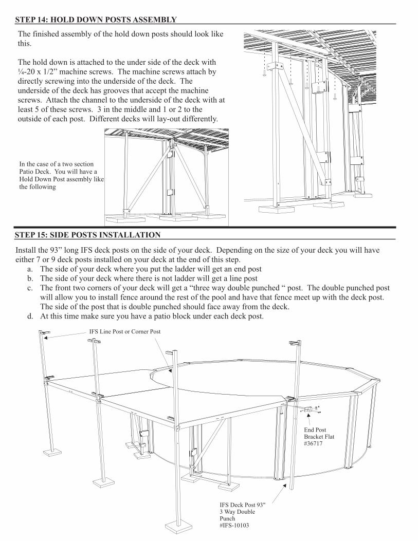
STEP 15: SIDE POSTS INSTALLATION
Install the 93” long IFS deck posts on the side of your deck. Depending on the size of your deck you will have either 7 or 9 deck posts installed on your deck at the end of this step.
a. The side of your deck where you put the ladder will get an end postb. The side of your deck where there is not ladder will get a line postc. The front two corners of your deck will get a “three way double punched “ post. The double punched post
will allow you to install fence around the rest of the pool and have that fence meet up with the deck post. The side of the post that is double punched should face away from the deck.
d. At this time make sure you have a patio block under each deck post.
End Post Bracket Flat#36717
IFS Deck Post 93" 3 Way Double Punch#IFS-10103
IFS Line Post or Corner Post
In the case of a two section Patio Deck. You will have a Hold Down Post assembly like the following

STEP 16: UNDER DECK POSTS INSTALLATION
Underneath your deck, install 53-1/4” long support posts. These posts come with a small channel already attached to them. The slot in the channel will allow you to use a machine screw and install the channel/post directly to the underside of the deck. Prior to install, you will have to drill two 9/32" holes into the deck board flange on the under side of the deck. See the foot print for your deck at the back of the instructions for the location of each of these supports.
At this time make sure you have a patio block under each support post.
1/4-20 X 1/2" Machine Screws
Support Post with Bracket 53-1/4"#29689
STEP 17: POST ANCHOR & SHORT FENCE INSTALLATION
The front corners of your deck require the installation of a post anchor. This anchor is a footing for a fence post. The anchor is installed in the front corners of the deck, close to the water. Looking carefully you will find the holes already drilled in your deck. There is a slot and a hole in the post that sticks up from the anchor. It is important to orient the slot and hole as shown in the installation instructions. At the same time, you will have to install the short fence section. See instructions below. NOTE:There is no Anchor with a 12' Radius Deck
Insert the Post onto the Post Ancor
Attach the short Fence clips.Short Fence Clips are 6-1/8". Make sure you don ’t mix with the long ones (6-3/4")
Attach post and Ancor with two machine screws (1/4-20 x 1-7/8"), nuts and Screw Covers.
Insert the Short Fence Section:- Slide into the Three Way Corner Post clips
- Slide the Post-Anchor assembly onto Fence Section
11 2 3 4
5 6Use Machine Screws(1/4-20 x 3/4") and Nuts to secure the assembly
7
Use Self taping Screws and Nuts to secure Fence Clips and Fence Section
INSTALL ON BOTH SIDES OF THE DECK
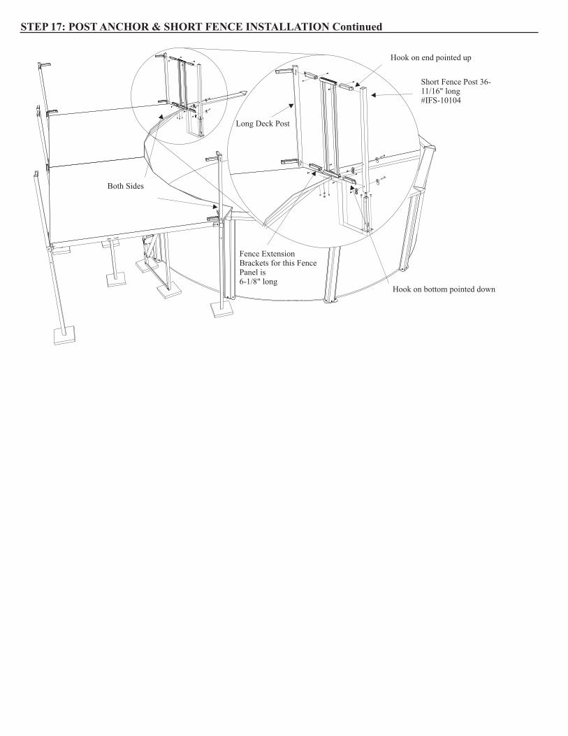
STEP 17: POST ANCHOR & SHORT FENCE INSTALLATION Continued
Hook on bottom pointed down
Fence Extension Brackets for this Fence Panel is 6-1/8" long
Short Fence Post 36-11/16" long#IFS-10104
Hook on end pointed up
Long Deck Post
Both Sides

STEP 18: IFS FENCE PANEL IDENTIFICATION CHART
The Fence panel for the IFS (Integrated Fence System) is adjustable. Each rail of the fence has a bracket that allows the fence
to slide inside of it. That gives the fence a range of adjustment. The brackets at the ends of the rail are called Fence
Adjustment Clips. The brackets are 6-3/4” long. The Fence Clips are attached to the fence with self-tapping screws.
a. Self tapping screws do not require you to drill a hole. Using a cordless screw driver the screws will self-drill and
attach to the fence rail.
b. There are four (4) Clips used on each fence panel. The top two Clips are installed with the hook facing “up” and the
bottom two Clips are installed with the hook facing “down” as per the diagram.
c. Because the fence panels are adjustable they can be measured several ways. See the chart for how to measure and
determine which fence panels go in which opening between fence posts.
FencePost
Fence Post Holder
PART NUMBER
11513
29751
IFS-10122
IFS-10001
99-0023
99-0016
99-0017
99-0118
11498
PART NUMBER
LENGTH OF PANEL
WITH NO
BRACKETS
MINIMUM
OPENING WITH
BRACKETS ON THE
ENDS OF THE PANEL
MAXIMUM
OPENING WITH
BRACKETS ON THE
ENDS OF THE PANEL
NUMBER OF
PICKETS ON PANEL
IFS-10111 7-7/16" 11-1/4" 15-1/4" 2
IFS-10112 12-3/4" 15-1/16" 20-1/4" 3
IFS-10113 18-1/16" 20-5/16" 25-1/2" 4
IFS-10114 23-3/8" 25-5/8" 30-7/8" 5
IFS-10115 28-5/8" 30-15/16" 36-1/4" 6
IFS-10116 34" 36-5/16" 41-1/2" 7
IFS-10117 39-5/16" 41-9/16" 46-13/16" 8
IFS-10118 44-5/8" 46-7/8" 52-1/8" 9
IFS-10119 49-15/16" 52-3/16" 57-7/16" 10
IFS-10120 55-1/4" 57-1/2" 62-3/4" 11
IFS FENCE PANEL IDENTIFICATION CHART
INTEGRITY FENCE SYSTEM PARTS LIST
POST HOLDER TAUPE (METAL UPRIGHT)
ATM POST HOLDER TAUPE (RESIN UPRIGHT)
DESCRIPTION
IFS FENCE POST TAUPE 50 5/16"
IFS FENCE CLIP ADJUSTABLE 6-3/4" TAUPE (3634)
MACHINE SCREW 1/4-20 X 3/4" 18-8 SS PHIL TRUSS
NUT 1/4-20 18-8 SS SERRATED FLANGE
FENCE POST CAP SINGLE TAUPE
MACHINE SCREW 1/4-20 X 2" 18-8 SS PHIL TRUSS
SCREW #8X1/2 PHIL PAN TEK PTD TAUPE
Note the direction of the hook on the Fence Clip

STEP 19: FENCE PANEL LAYOUT
Lay our all the fence panels that will go on your deck on the ground around the deck. At the same time, install the missing
posts. This has to be done at the same time. The foot print of your deck at the back of the instructions shows which length
of fence goes between which fence posts. Before you install any fence sections make sure that you have the proper fence
section in the proper location. Continue around the deck installing fence sections. The fence extension is 6-3/4” long on all
these fence sections.
a. Do not screw in any of the fence sections at this time. Leave them so that you can adjust them in the bracket once all
the panels are attached to the deck
b. Make sure that you have left one opening on your deck where your ground-to-deck ladder will be installed.
Do not screw the Fence Section into position at this time
NOTE: The top of the Fence Panel has a screw cover over it. Make sure to install the Fence Panel the right way.
STEP 20: ATTACH FENCE SECTIONS
Assemble all sections along with the posts and center them in the space between the posts. You can slide them easily in the
brackets at this time. Once they are all centered then use self-tapping screws, with painted screw heads, to attach the fence
to the adjustable brackets. Use the self-tapping screws on both the inside and the outside of each fence bracket.
#8 X 5/8" Self Taping Screw with a painted head to match the fence#99-0118

STEP 21: ATTACH BRACE BRACKETS
The deck is braced by a series of diagonal braces attached to the deck posts. The diagonal braces are made from square
tubing. The diagonal tubes are attached to the deck posts with brackets. There are 3 types of brackets on your deck: Line,
Corner, End.
a. The brackets are attached with a machine screw and nut using the pre-drilled hole in the deck post.
b.At this time attach the Line bracket to each of the posts indicated below.
i. If you have a larger deck the line bracket will be attached to two posts, but not the middle post. The drawing
below shows the larger deck.
ii. If you have a smaller deck the line bracket will only be attached to the middle post.
iii. For all decks the middle post on the side of the deck requires a line bracket
Pre-DrilledHoles
#IFS-10109
Diagonal Brace made from 1-1/2" square tube
Install all diagonal braces with the screw head facing out and the nut to the inside of the deck
STEP 22: ATTACH DIAGONAL BRACES
Diagonal braces should now be attached to each of the line brackets. When you are done with this step only one end of each
diagonal brace will be attached. Refer to the footprint of your deck at the back of the instructions so you know which length
diagonal brace is installed at which location on your deck. The head of the screw should be on the outside of the brace and
the nut should always be on the side that is underneath the deck.
1/4-20 x 2" Machine Screw
Before installing the Diagonal Braces, you must install the 1-1/2" square Male Plugs into the top end of the Braces.

STEP 23: ATTACH CONNECTORS
At this time attach the connectors at the bottom of each diagonal brace. Using the diagonal brace as a guide attach the line and corner brackets to the posts.
a. Attach each line bracket to the diagonal braces as shown.b. Attach each corner bracket to the diagonal braces as shown.
Corner Bracket#IFS-10108
STEP 24: ANGLES INSTALLATION
Install angle around the bottom of the deck and across the underside of the deck as shown. Overlap the angles in and around the deck so that they do not stick out past the deck posts. Use self-tapping screws to attach the angle to the deck posts.
End Bracket#IFS-10110
On the posts, there will be extra holes that are not used in the installation. Please plug them with this Christmas Tree #38140 in order to cover all exposed holes.
11
1
11
2
2
3
3
3
3
Sequence of installation is important:1- Install short ones in the middle2- Install the long ones in the middle3- Install the ones around the perimeter

Drill out in step2 holes Ø.281'' (9/32")
STEP 25: LADDER ASSEMBLY
Assemble your ground to deck ladder. Arrange the parts and install them using machine screws and nuts as shown.
STEP 26: ATTACH LADDER TO DECK
Attach the ground to deck ladder to the deck by drilling and screwing in the stainless steel hinges on the top of the ladder and the deck as shown.

STEP 27: LOCATING THE LATCH
Swing up the ladder in order to locate the latch. Once located attach the latch to the deck post as shown.
STEP 28: ATTACH LATCH TO DECK
Your deck is now finished. It is important that you fully inspect your deck at this time to make sure that all the fence sections, posts, panels, deck sections, ladders, braces and brackets are secure.
Latch