Embed Size (px)
Citation preview

IFE Ethernet Interface for LV Circuit Breaker
1040IB1401-02 05/2015
1040
IB14
01-0
2
www.schneider-electric.com
IFE Ethernet Interface for LV Circuit BreakerUser Guide
05/2015
The information provided in this documentation contains general descriptions and/or technical characteristics of the performance of the products contained herein. This documentation is not intended as a substitute for and is not to be used for determining suitability or reliability of these products for specific user applications. It is the duty of any such user or integrator to perform the appropriate and complete risk analysis, evaluation and testing of the products with respect to the relevant specific application or use thereof. Neither Schneider Electric nor any of its affiliates or subsidiaries shall be responsible or liable for misuse of the information contained herein. If you have any suggestions for improvements or amendments or have found errors in this publication, please notify us.
No part of this document may be reproduced in any form or by any means, electronic or mechanical, including photocopying, without express written permission of Schneider Electric.
All pertinent state, regional, and local safety regulations must be observed when installing and using this product. For reasons of safety and to help ensure compliance with documented system data, only the manufacturer should perform repairs to components.
When devices are used for applications with technical safety requirements, the relevant instructions must be followed.
Failure to use Schneider Electric software or approved software with our hardware products may result in injury, harm, or improper operating results.
Failure to observe this information can result in injury or equipment damage.
© 2015 Schneider Electric. All rights reserved.
2 1040IB1401-02 05/2015

Table of Contents
Safety Information . . . . . . . . . . . . . . . . . . . . . . . . . . . . . . . . . . . . . . . . . . . 5About the Book . . . . . . . . . . . . . . . . . . . . . . . . . . . . . . . . . . . . . . . . . . . . . 7
Chapter 1 IFE Presentation . . . . . . . . . . . . . . . . . . . . . . . . . . . . . . . . . . . . . . . . . . . . 9Introduction . . . . . . . . . . . . . . . . . . . . . . . . . . . . . . . . . . . . . . . . . . . . . . . . . . . . . . . . . . . . . . 10Hardware Description. . . . . . . . . . . . . . . . . . . . . . . . . . . . . . . . . . . . . . . . . . . . . . . . . . . . . . . 13Customer Engineering Tool . . . . . . . . . . . . . . . . . . . . . . . . . . . . . . . . . . . . . . . . . . . . . . . . . . 16Schematics with Masterpact NT/NW and PowerPact P- and R-Frame Circuit Breakers . . . . 17Schematics with PowerPact H-, J-, and L-Frame Circuit Breakers . . . . . . . . . . . . . . . . . . . . 22Technical Characteristics . . . . . . . . . . . . . . . . . . . . . . . . . . . . . . . . . . . . . . . . . . . . . . . . . . . . 27Firmware Update . . . . . . . . . . . . . . . . . . . . . . . . . . . . . . . . . . . . . . . . . . . . . . . . . . . . . . . . . . 29Protecting the Environment . . . . . . . . . . . . . . . . . . . . . . . . . . . . . . . . . . . . . . . . . . . . . . . . . . 31
Chapter 2 IFE Web Server . . . . . . . . . . . . . . . . . . . . . . . . . . . . . . . . . . . . . . . . . . . . . 332.1 IFE Ethernet Interface for LV Circuit Breaker. . . . . . . . . . . . . . . . . . . . . . . . . . . . . . . . . . . . . 34
Access to IFE Webpages. . . . . . . . . . . . . . . . . . . . . . . . . . . . . . . . . . . . . . . . . . . . . . . . . . . . 35User Interface Layout. . . . . . . . . . . . . . . . . . . . . . . . . . . . . . . . . . . . . . . . . . . . . . . . . . . . . . . 38Webpage Description. . . . . . . . . . . . . . . . . . . . . . . . . . . . . . . . . . . . . . . . . . . . . . . . . . . . . . . 40
2.2 IFE Web Server - Configuration & Settings Pages . . . . . . . . . . . . . . . . . . . . . . . . . . . . . . . . 42Device Location/Name . . . . . . . . . . . . . . . . . . . . . . . . . . . . . . . . . . . . . . . . . . . . . . . . . . . . . . 43Device Name . . . . . . . . . . . . . . . . . . . . . . . . . . . . . . . . . . . . . . . . . . . . . . . . . . . . . . . . . . . . . 44Ethernet Configuration (Dual Port) . . . . . . . . . . . . . . . . . . . . . . . . . . . . . . . . . . . . . . . . . . . . . 45IP Configuration . . . . . . . . . . . . . . . . . . . . . . . . . . . . . . . . . . . . . . . . . . . . . . . . . . . . . . . . . . . 46Modbus TCP/IP Filtering . . . . . . . . . . . . . . . . . . . . . . . . . . . . . . . . . . . . . . . . . . . . . . . . . . . . 48Serial Port . . . . . . . . . . . . . . . . . . . . . . . . . . . . . . . . . . . . . . . . . . . . . . . . . . . . . . . . . . . . . . . 49Date and Time . . . . . . . . . . . . . . . . . . . . . . . . . . . . . . . . . . . . . . . . . . . . . . . . . . . . . . . . . . . . 50Email Server Configuration . . . . . . . . . . . . . . . . . . . . . . . . . . . . . . . . . . . . . . . . . . . . . . . . . . 51Alarms to Email . . . . . . . . . . . . . . . . . . . . . . . . . . . . . . . . . . . . . . . . . . . . . . . . . . . . . . . . . . . 53Device List . . . . . . . . . . . . . . . . . . . . . . . . . . . . . . . . . . . . . . . . . . . . . . . . . . . . . . . . . . . . . . . 56Device Logging . . . . . . . . . . . . . . . . . . . . . . . . . . . . . . . . . . . . . . . . . . . . . . . . . . . . . . . . . . . 61Device Log Export . . . . . . . . . . . . . . . . . . . . . . . . . . . . . . . . . . . . . . . . . . . . . . . . . . . . . . . . . 63SNMP Parameters . . . . . . . . . . . . . . . . . . . . . . . . . . . . . . . . . . . . . . . . . . . . . . . . . . . . . . . . . 64Documentation Links . . . . . . . . . . . . . . . . . . . . . . . . . . . . . . . . . . . . . . . . . . . . . . . . . . . . . . . 65Preferences . . . . . . . . . . . . . . . . . . . . . . . . . . . . . . . . . . . . . . . . . . . . . . . . . . . . . . . . . . . . . . 66Advanced Services Control . . . . . . . . . . . . . . . . . . . . . . . . . . . . . . . . . . . . . . . . . . . . . . . . . . 67User Accounts . . . . . . . . . . . . . . . . . . . . . . . . . . . . . . . . . . . . . . . . . . . . . . . . . . . . . . . . . . . . 68Webpage Access . . . . . . . . . . . . . . . . . . . . . . . . . . . . . . . . . . . . . . . . . . . . . . . . . . . . . . . . . . 69
2.3 IFE Web Server - Monitoring Pages . . . . . . . . . . . . . . . . . . . . . . . . . . . . . . . . . . . . . . . . . . . 70Real Time Data . . . . . . . . . . . . . . . . . . . . . . . . . . . . . . . . . . . . . . . . . . . . . . . . . . . . . . . . . . . 71Device Logging . . . . . . . . . . . . . . . . . . . . . . . . . . . . . . . . . . . . . . . . . . . . . . . . . . . . . . . . . . . 73
2.4 IFE Web Server - Control Page . . . . . . . . . . . . . . . . . . . . . . . . . . . . . . . . . . . . . . . . . . . . . . . 77Single Device Control. . . . . . . . . . . . . . . . . . . . . . . . . . . . . . . . . . . . . . . . . . . . . . . . . . . . . . . 77
2.5 IFE Web Server - Diagnostics Pages. . . . . . . . . . . . . . . . . . . . . . . . . . . . . . . . . . . . . . . . . . . 79Statistics. . . . . . . . . . . . . . . . . . . . . . . . . . . . . . . . . . . . . . . . . . . . . . . . . . . . . . . . . . . . . . . . . 80Device Information . . . . . . . . . . . . . . . . . . . . . . . . . . . . . . . . . . . . . . . . . . . . . . . . . . . . . . . . . 82IMU Information . . . . . . . . . . . . . . . . . . . . . . . . . . . . . . . . . . . . . . . . . . . . . . . . . . . . . . . . . . . 83Read Device Registers . . . . . . . . . . . . . . . . . . . . . . . . . . . . . . . . . . . . . . . . . . . . . . . . . . . . . 84Communication Check . . . . . . . . . . . . . . . . . . . . . . . . . . . . . . . . . . . . . . . . . . . . . . . . . . . . . . 85IO Module. . . . . . . . . . . . . . . . . . . . . . . . . . . . . . . . . . . . . . . . . . . . . . . . . . . . . . . . . . . . . . . . 86
1040IB1401-02 05/2015 3

2.6 IFE Web Server - Maintenance Pages . . . . . . . . . . . . . . . . . . . . . . . . . . . . . . . . . . . . . . . . . . 87Maintenance Log . . . . . . . . . . . . . . . . . . . . . . . . . . . . . . . . . . . . . . . . . . . . . . . . . . . . . . . . . . 88Maintenance Counters . . . . . . . . . . . . . . . . . . . . . . . . . . . . . . . . . . . . . . . . . . . . . . . . . . . . . . 89Restore the Smartlink’s. . . . . . . . . . . . . . . . . . . . . . . . . . . . . . . . . . . . . . . . . . . . . . . . . . . . . . 90
Appendices . . . . . . . . . . . . . . . . . . . . . . . . . . . . . . . . . . . . . . . . . . . . . . . . . . . . . 91Appendix A Appendix A - List of IFE Supported Devices . . . . . . . . . . . . . . . . . . . . . 93
List of IFE Supported Device Types . . . . . . . . . . . . . . . . . . . . . . . . . . . . . . . . . . . . . . . . . . . . 93
4 1040IB1401-02 05/2015
Safety Information
Important Information
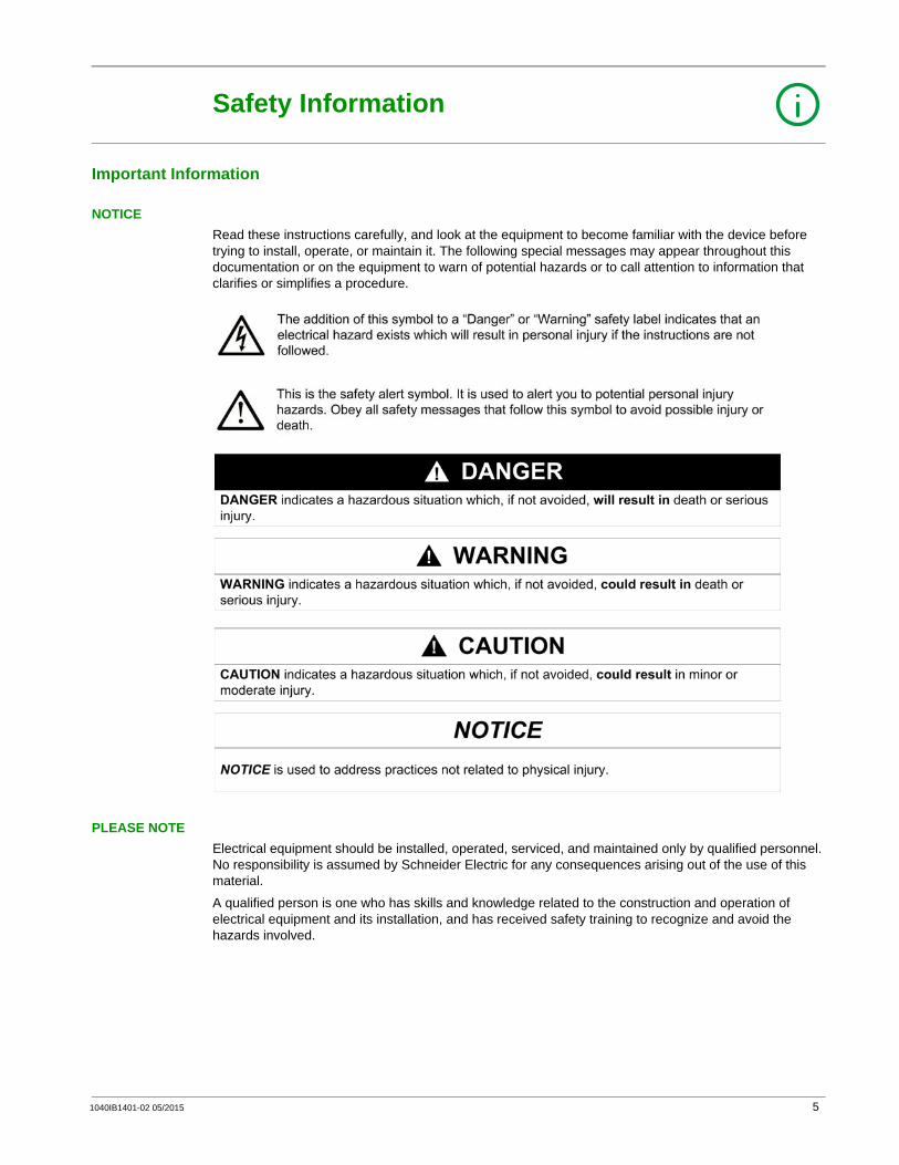
NOTICERead these instructions carefully, and look at the equipment to become familiar with the device before trying to install, operate, or maintain it. The following special messages may appear throughout this documentation or on the equipment to warn of potential hazards or to call attention to information that clarifies or simplifies a procedure.
PLEASE NOTEElectrical equipment should be installed, operated, serviced, and maintained only by qualified personnel. No responsibility is assumed by Schneider Electric for any consequences arising out of the use of this material.
A qualified person is one who has skills and knowledge related to the construction and operation of electrical equipment and its installation, and has received safety training to recognize and avoid the hazards involved.
1040IB1401-02 05/2015 5

FCC NoticeThis equipment has been tested and found to comply with the limits for a Class A digital device, pursuant to part 15 of the FCC Rules. These limits are designated to provide reasonable protection against harmful interference when the equipment is operated in a commercial environment. This equipment generates, uses, and can radiate radio frequency energy and, if not installed and used in accordance with the instruction manual, may cause harmful interference to radio communications. Operation of this equipment in a residential area is likely to cause harmful interference in which case the user will be required to correct the interference at this own expense.
6 1040IB1401-02 05/2015
About the Book
At a Glance
Document ScopeThe aim of this document is to provide the users, installers, and the maintenance personnel with the technical information and procedure needed to access and maintain the IFE web server.
Validity NoteThe technical characteristics of the devices described in this document also appear online. To access this information online:
The characteristics that are presented in this manual should be the same as those characteristics that appear online. In line with our policy of constant improvement, we may revise content over time to improve clarity and accuracy. If you see a difference between the manual and online information, use the online information as your reference.
Related Documents
You can download these technical publications and other technical information from our website at www.schneider-electric.com.
Step Action
1 Go to the Schneider Electric home page www.schneider-electric.com.
2 In the Search box type the reference of a product or the name of a product range.Do not include blank spaces in the reference or product range.To get information on grouping similar modules, use asterisks (*).
3 If you entered a reference, go to the Product Datasheets search results and click on the reference that interests you.If you entered the name of a product range, go to the Product Ranges search results and click on the product range that interests you.
4 If more than one reference appears in the Products search results, click on the reference that interests you.
5 Depending on the size of your screen, you may need to scroll down to see the data sheet.
6 To save or print a data sheet as a .pdf file, click Download XXX product datasheet.
Title of Documentation Reference Number
IFE Ethernet interface for LV circuit breaker - Instruction Sheet HRB49218
Masterpact NT/NW, PowerPact P- and R-frame Modbus Communication Guide
0613IB1313 (EN)0613IB1314 (ES)0613IB1315 (FR)0613IB1316 (ZH)
PowerPact H-, J-, and L-Frame Modbus Communication Guide 0611IB1302 (EN)0611IB1303 (ES)0611IB1304 (FR)0611IB1305 (ZH)
ULP System - User Guide 48940-329 (EN)48940-329 (ES)48940-329 (FR)
1040IB1401-02 05/2015 7

8 1040IB1401-02 05/2015

IFE Ethernet Interface for LV Circuit BreakerIFE Presentation1040IB1401-02 05/2015
IFE Presentation
Chapter 1IFE Presentation
What Is in This Chapter?This chapter contains the following topics:
Topic Page
Introduction 10
Hardware Description 13
Customer Engineering Tool 16
Schematics with Masterpact NT/NW and PowerPact P- and R-Frame Circuit Breakers 17
Schematics with PowerPact H-, J-, and L-Frame Circuit Breakers 22
Technical Characteristics 27
Firmware Update 29
Protecting the Environment 31
1040IB1401-02 05/2015 9
IFE Presentation
Introduction
OverviewThe IFE Ethernet interface for LV circuit breaker enables an intelligent modular unit (IMU), for example a Masterpact NT or PowerPact H-, J-, and L-Frame circuit breaker to be connected to an Ethernet network. Each circuit breaker has its own IFE and a corresponding IP address.
Types of IFEThere are 2 part numbers of the IFE:
LV434010 - Ethernet interface for LV circuit breakerThis type of IFE is an Ethernet interface for Compact, PowerPact, and Masterpact circuit breakers.LV434011 - Ethernet interface for LV circuit breaker and gatewayThis type of IFE is an Ethernet interface for Compact, PowerPact, and Masterpact circuit breakers and a gateway for Modbus-SL (serial line) connected devices.
IFE FeaturesThe main features of IFE are:
Dual Ethernet port for simple daisy chain connectionDevice profile web service for discovery of the IFE on the local area network (LAN)ULP compliant for localization of the IFE in the switchboardEthernet interface for Compact, PowerPact, and Masterpact circuit breakersGateway for Modbus-SL connected devices (only for the IFE with the part number LV434011)Embedded setup web pagesEmbedded monitoring web pagesEmbedded control web pagesBuilt-in email alarm notification
NOTE: IFE built-in switch does not support the ring topology as it does not have the feature of the loop back protection.
NOTE: IFE does not support the circuit breaker without Micrologic with BSCM and BCM ULP.
Intelligent Modular UnitA modular unit is a mechanical and electrical assembly containing one or more products to perform a function in a switchboard (incoming protection, motor command, and control).
The circuit breaker with its internal communicating components (Micrologic and so on) and external ULP modules (FDM121, IO module, and so on) connected to one IFM or IFE communication interface is called an intelligent modular unit (IMU).
10 1040IB1401-02 05/2015
IFE Presentation
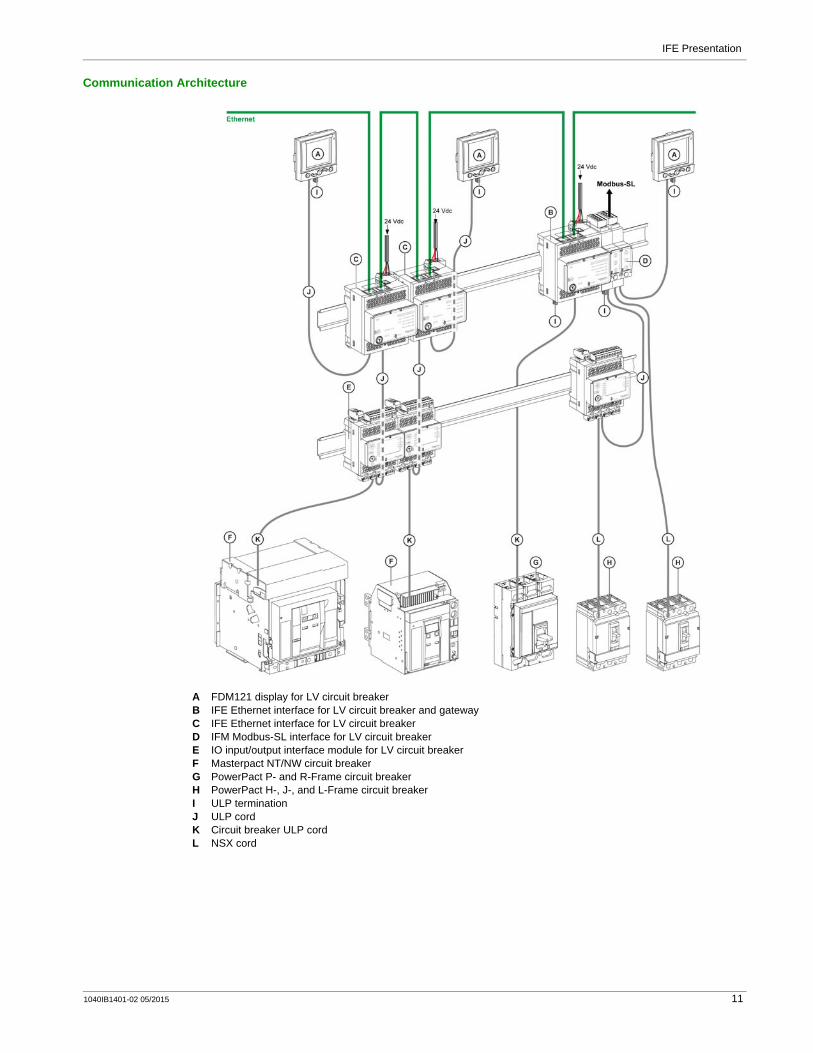
Communication Architecture
A FDM121 display for LV circuit breakerB IFE Ethernet interface for LV circuit breaker and gatewayC IFE Ethernet interface for LV circuit breakerD IFM Modbus-SL interface for LV circuit breakerE IO input/output interface module for LV circuit breakerF Masterpact NT/NW circuit breakerG PowerPact P- and R-Frame circuit breakerH PowerPact H-, J-, and L-Frame circuit breakerI ULP terminationJ ULP cordK Circuit breaker ULP cordL NSX cord
1040IB1401-02 05/2015 11

IFE Presentation
Component Part NumbersThe below table lists the part numbers for the components of the ULP system for the circuit breaker:
Product Description Part Number
IFM Modbus-SL interface for LV circuit breaker – STRV00210
IFE Ethernet interface for LV circuit breaker Ethernet interface LV434010
Ethernet interface and gateway LV434011
Stacking accessory 10 stacking accessories TRV00217
BCM ULP breaker communication module – 33106
BSCM breaker status control module – LV434205
IO input/output interface for LV circuit breaker – LV434063
FDM121 display for LV circuit breaker – STRV00121
Surface-mounting accessory – TRV00128
Maintenance module – STRV00911
NSX cord L = 0.35 m (1.15 ft) LV434200
L = 1.3 m (4.27 ft) LV434201
L = 3 m (9.84 ft) LV434202
Circuit Breaker ULP cord L = 0.35 m (1.15 ft) LV434195
L = 1.3 m (4.26 ft) LV434196
L = 3 m (9.84 ft) LV434197
Insulated ULP module and circuit breaker ULP cord for system voltage greater than 480 Vac
L = 1.3 m (4.26 ft), U > 480 Vac(cord with female socket)
LV434204
ULP cord L = 0.3 m (0.98 ft), 10 cords TRV00803
L = 0.6 m (1.97 ft), 10 cords TRV00806
L = 1 m (3.28 ft), 5 cords TRV00810
L = 2 m (6.56 ft), 5 cords TRV00820
L = 3 m (9.84 ft), 5 cords TRV00830
L = 5 m (16.40 ft), 1 cord TRV00850
RJ45 female/female connector 10 RJ45 female/female connectors TRV00870
ULP line termination 10 ULP terminations TRV00880
2-wire RS 485 isolated repeater module – TRV00211
Modbus line termination 2 Modbus cable terminations with impedance of 120 Ω + 1 nF
VW3A8306DRC
Modbus cable Belden: 7 mm (0.27 in.) diameter shielded cable with 2 twisted pairs
3084A
Belden: 9.6 mm (0.38 in.) diameter (recommended) shielded cable with 2 twisted pairs
7895A
Cable with 2 twisted pairs without shielding drain wire
50965
24 Vdc power supply 24/30 Vdc-24 Vdc-1 A-overvoltage category IV 685823
48/60 Vdc-24 Vdc-1 A-overvoltage category IV 685824
100/125 Vdc-24 Vdc-1 A-overvoltage category IV
685825
110/130 Vac-24 Vdc-1 A-overvoltage category IV
685826
200/240 Vac-24 Vdc-1 A-overvoltage category IV
685827
380/415 Vac-24 Vdc-1 A-overvoltage category IV
685829
100/500 Vac-24 Vdc-3 A-overvoltage category II ABL8RPS24030
12 1040IB1401-02 05/2015

IFE Presentation
Hardware Description
Description
A Ethernet 1 and Ethernet 2 RJ45 communication portsB 24 Vdc power supply terminal block C Ethernet communication LEDsD Module status LEDE Network status LEDF Sealable transparent coverG Reset buttonH ULP status LEDI Test button (accessible cover closed)J Locking padK Modbus traffic status LED (IFE gateway only)L Device name labelM 2 RJ45 ULP ports
MountingThe IFE mounts on a DIN rail. The stacking accessory enables the connection of several IFMs to an IFE gateway without additional wiring.
NOTE: The stacking feature is available only for the IFE gateway with the part number LV434011.
24 Vdc Power SupplyThe IFE must be always supplied with 24 Vdc. The IFMs stacked to an IFE gateway are supplied by the IFE gateway and it is not necessary to supply them separately.
It is recommended to use an UL listed and recognized limited voltage/limited current or a class 2 power supply with a 24 Vdc, 3 A maximum.
1040IB1401-02 05/2015 13
IFE Presentation
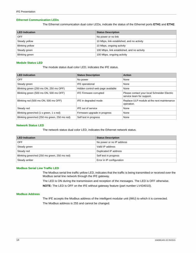
Ethernet Communication LEDsThe Ethernet communication dual color LEDs, indicate the status of the Ethernet ports ETH1 and ETH2.
Module Status LEDThe module status dual color LED, indicates the IFE status.
Network Status LEDThe network status dual color LED, indicates the Ethernet network status.
Modbus Serial Line Traffic LEDThe Modbus serial line traffic yellow LED, indicates that the traffic is being transmitted or received over the Modbus serial line network through the IFE gateway.
The LED is ON during the transmission and reception of the messages. The LED is OFF otherwise.
NOTE: The LED is OFF on the IFE without gateway feature (part number LV434010).
Modbus AddressThe IFE accepts the Modbus address of the intelligent modular unit (IMU) to which it is connected.
The Modbus address is 255 and cannot be changed.
LED Indication Status Description
OFF No power or no link
Steady yellow 10 Mbps, link established, and no activity
Blinking yellow 10 Mbps, ongoing activity
Steady green 100 Mbps, link established, and no activity
Blinking green 100 Mbps, ongoing activity
LED Indication Status Description Action
OFF No power None
Steady green IFE operational None
Blinking green (250 ms ON, 250 ms OFF) Hidden control web page available None
Blinking green (500 ms ON, 500 ms OFF) IFE Firmware corrupted Please contact your local Schneider Electric service team for support.
Blinking red (500 ms ON, 500 ms OFF) IFE in degraded mode Replace ULP module at the next maintenance operation.
Steady red IFE out of service None
Blinking green/red (1 s green, 1 s red) Firmware upgrade in progress None
Blinking green/red (250 ms green, 250 ms red) Self test in progress None
LED Indication Status Description
OFF No power or no IP address
Steady green Valid IP address
Steady red Duplicated IP address
Blinking green/red (250 ms green, 250 ms red) Self test in progress
Steady amber Error in IP configuration
14 1040IB1401-02 05/2015

IFE Presentation
Locking PadThe locking pad on the front panel of the IFE enables or disables the ability to send the remote control commands over the Ethernet network to the IFE, and to the other modules of the connected IMU.
If the arrow points to the open padlock (factory setting), remote control commands are enabled.If the arrow points to the closed padlock, remote control commands are disabled.The only remote control command that is enabled even if the arrow points to the closed padlock is the set absolute time command.
Test ButtonThe test button has two functions, according to the duration of the button pressed.
Reset ButtonWhen the reset button is pressed for 1–5 seconds, it forces the IP acquisition mode to the factory default setting (DHCP).
ULP LEDThe yellow ULP LED describes the mode of the ULP module.
Time Range Function
1–5 s Tests the connection between all the ULP modules for 15 seconds.
10–15 s Activates the hidden configuration mode for 5 minutes.
NOTE: The hidden configuration is not activated if the button is pressed for more than 15 s.
ULP LED Mode Action
Nominal None
Conflict Remove extra ULP module
Degraded Replace ULP module at the next maintenance operation
Test None
Non-critical firmware discrepancy
Upgrade firmware at the next maintenance operation
Non-critical hardware discrepancy
Replace ULP module at the next maintenance operation
Configuration discrepancy
Install missing features
Critical firmware discrepancy
Upgrade firmware
Critical hardware discrepancy
Replace ULP module
Stop Replace ULP module
Power OFF Check power supply
1040IB1401-02 05/2015 15

IFE Presentation
Customer Engineering Tool
EcoreachEcoreach is a software application that helps to manage a project as part of testing, site commissioning and maintenance phases of the project life cycle. It enables to prepare the settings of the devices offline (without connecting to the device), save the project in cloud as reference, and configure the devices when connected with the devices. Also it offers value added features like discover communicating devices, organize devices in switchboard, manage a hierarchical structure of the electrical installation, perform communication test, generate reports, upgrade firmware, and so on.
The Ecoreach software enables the configuration of the following devices, modules, accessories:
For more information, refer to the Ecoreach Online Help.
Ecoreach Software FeaturesEcoreach software allows you to perform the following actions:
Create projects by device discovery and selection of devices from Schneider Electric catalogMonitor the status of protection and IO statusRead information like, alarms, measurements, parametersConfiguration or settings download and upload for single or multiple devicesPerform control actions in a secured wayGenerate and print device settings report and communication test reportManage multiple devices with electrical and communication hierarchy modelManage artifacts (project and device documents)Check consistency in settings between devices in a communication networkCompare configuration settings between the project and device (online)Download latest firmware and upgrade devicesSafe repository of projects in Ecoreach cloud and sharing of projects with other users
Legacy SoftwareThe Ecoreach software replaces the following legacy software:
Compact NSX RSU (Remote Setting Utility): PowerPact H-, J-, and L-frame configuration software.Masterpact RSU (Remote Setting Utility): Masterpact and PowerPact P- and R-frame configuration software.RCU (Remote Control Utility): A SCADA software for:
PowerPact H-, J-, and L-frame circuit breakersPowerPact P- and R-frame circuit breakersMasterpact NT/NW circuit breakersPower meters
The legacy software is available at www.schneider-electric.com.
Products–Family ULP/IMU Modules Accessories
Masterpact NT/NW circuit breakersPowerPact P- and R-Frame circuit breakers
Micrologic trip unitsCommunication interface modules: BCM, CCM, BCM ULP IFM, IFEULP modules: IO module, FDM121 display unit (1)
M2C and M6C output modules
PowerPact H-, J-, and L-frame circuit breaker Micrologic trip unitsCommunication interface modules: BSCM, IFM, IFEULP modules: IO module, FDM121 display unit (1)
SDTAM and SDx output modules
(1) For FDM121 module, only the firmware and language download are supported.
16 1040IB1401-02 05/2015

IFE Presentation
Schematics with Masterpact NT/NW and PowerPact P- and R-Frame Circuit Breakers
DescriptionDepending on the type of circuit breaker used, connect the IFE Ethernet interface for LV circuit breaker to the circuit breaker using one of the following configurations:
Connection of the IFE to a fixed manually-operated PowerPact P- or R-frame circuit breaker with a BCM ULP.Connection of the IFE to a fixed electrically-operated Masterpact NT/NW or PowerPact P-frame circuit breaker with a BCM ULP.Connection of the IFE to a drawout Masterpact NT/NW or PowerPact P-frame circuit breaker with a BCM ULP and its respective IO input/output interfaces for LV circuit breakers.
ULP Connection
All connection configurations require the circuit breaker ULP cord. The insulated NSX cord is mandatory for system voltages greater than 480 Vac.
When the second RJ45 ULP port is not used, it must be closed with a ULP termination.
A ULP cordB ULP termination
NOTICEHAZARD OF EQUIPMENT DAMAGE
Never connect an Ethernet device to a RJ45 ULP port. The IFE RJ45 ULP ports are for ULP modules only.Any other use can damage the IFE or the device connected to the IFE.To check if a ULP module is compatible with the IFE’s RJ45 ULP ports, refer to the ULP System User Guide.
Failure to follow these instructions can result in equipment damage.
1040IB1401-02 05/2015 17

IFE Presentation
Connection of the IFE to a Fixed Manually-Operated PowerPact P- or R-Frame Circuit Breaker
A IFE Ethernet interface for LV circuit breakerB ULP terminationC Circuit breaker ULP cordD BCM ULP breaker communication moduleE Fixed manually-operated PowerPact P- or R-frame circuit breaker
18 1040IB1401-02 05/2015

IFE Presentation
Connection of the IFE to a Fixed Electrically-Operated Masterpact NT/NW or PowerPact P-Frame Circuit Breaker
A IFE Ethernet interface for LV circuit breakerB ULP terminationC Circuit breaker ULP cordD Fixed terminal blockE BCM ULP breaker communication moduleF Fixed electrically-operated circuit breaker
1040IB1401-02 05/2015 19

IFE Presentation
Connection of the IFE to a Drawout Masterpact NT/NW or PowerPact P-Frame Circuit Breaker
A IFE Ethernet interface for LV circuit breakerB ULP terminationC ULP cordD Circuit breaker ULP cordE Circuit breaker disconnected position contact (CD)F Circuit breaker cradleG BCM ULP breaker communication module H Drawout circuit breakerI Drawout terminal blockJ Circuit breaker connected position contact (CE)K Circuit breaker test position contact (CT)L IO input/output interface for LV circuit breaker
20 1040IB1401-02 05/2015
IFE Presentation
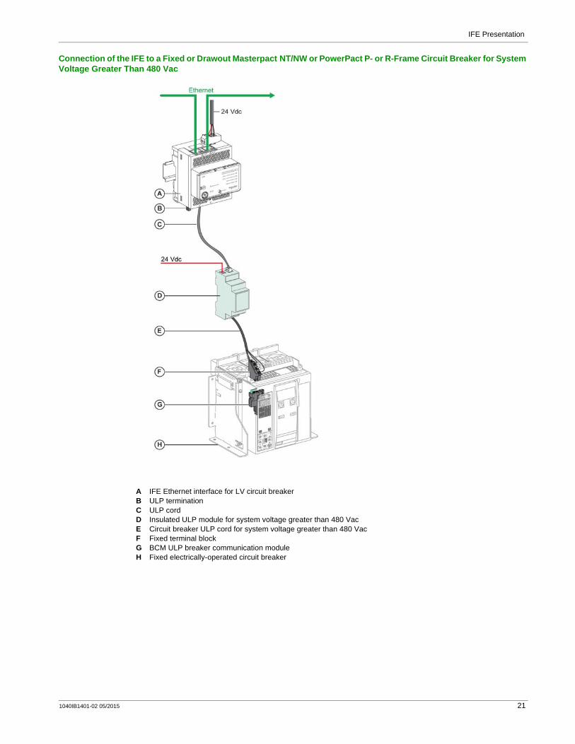
Connection of the IFE to a Fixed or Drawout Masterpact NT/NW or PowerPact P- or R-Frame Circuit Breaker for System Voltage Greater Than 480 Vac
A IFE Ethernet interface for LV circuit breakerB ULP terminationC ULP cordD Insulated ULP module for system voltage greater than 480 VacE Circuit breaker ULP cord for system voltage greater than 480 VacF Fixed terminal blockG BCM ULP breaker communication module H Fixed electrically-operated circuit breaker
1040IB1401-02 05/2015 21
IFE Presentation
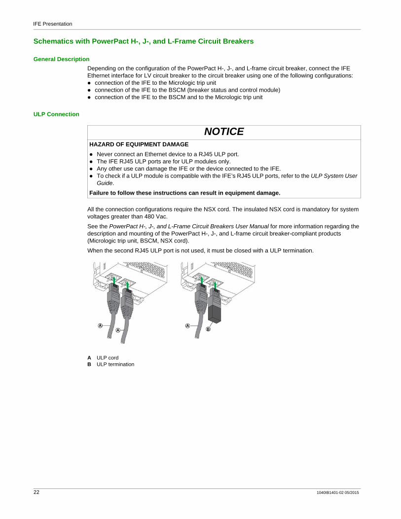
Schematics with PowerPact H-, J-, and L-Frame Circuit Breakers
General DescriptionDepending on the configuration of the PowerPact H-, J-, and L-frame circuit breaker, connect the IFE Ethernet interface for LV circuit breaker to the circuit breaker using one of the following configurations:
connection of the IFE to the Micrologic trip unitconnection of the IFE to the BSCM (breaker status and control module)connection of the IFE to the BSCM and to the Micrologic trip unit
ULP Connection
All the connection configurations require the NSX cord. The insulated NSX cord is mandatory for system voltages greater than 480 Vac.
See the PowerPact H-, J-, and L-Frame Circuit Breakers User Manual for more information regarding the description and mounting of the PowerPact H-, J-, and L-frame circuit breaker-compliant products (Micrologic trip unit, BSCM, NSX cord).
When the second RJ45 ULP port is not used, it must be closed with a ULP termination.
A ULP cordB ULP termination
NOTICEHAZARD OF EQUIPMENT DAMAGE
Never connect an Ethernet device to a RJ45 ULP port.The IFE RJ45 ULP ports are for ULP modules only.Any other use can damage the IFE or the device connected to the IFE.To check if a ULP module is compatible with the IFE’s RJ45 ULP ports, refer to the ULP System User Guide.
Failure to follow these instructions can result in equipment damage.
22 1040IB1401-02 05/2015

IFE Presentation
Connection of the IFE to the Micrologic Trip UnitConnect the IFE to the Micrologic trip unit using the NSX cord:
A IFE Ethernet interface for LV circuit breakerB ULP terminationC NSX cordD Micrologic trip unit
1040IB1401-02 05/2015 23
IFE Presentation
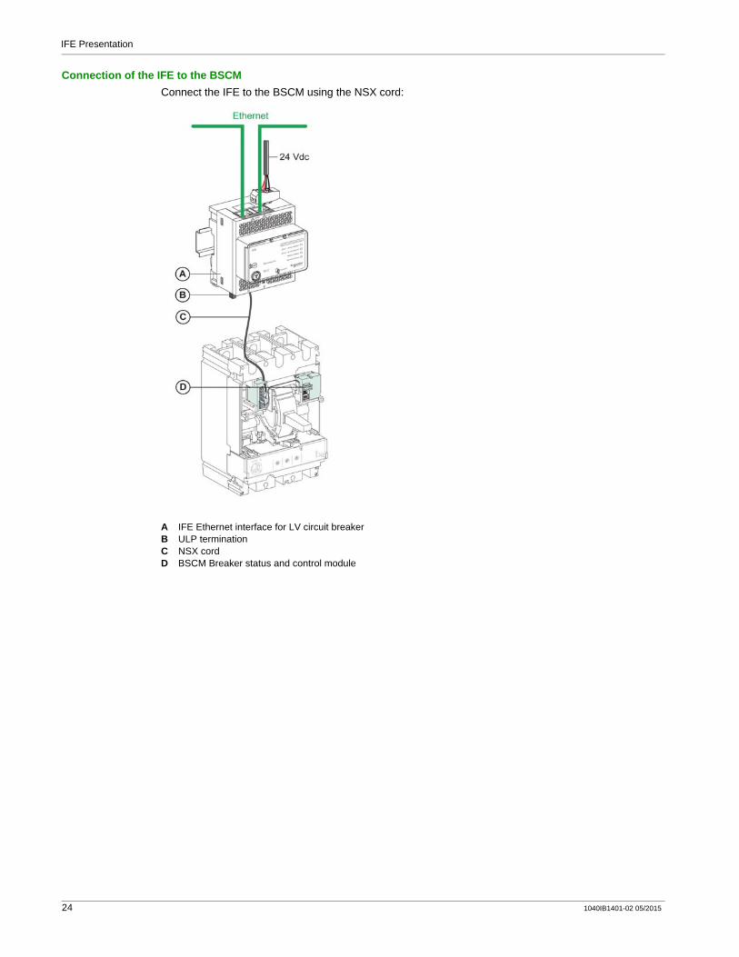
Connection of the IFE to the BSCMConnect the IFE to the BSCM using the NSX cord:
A IFE Ethernet interface for LV circuit breakerB ULP terminationC NSX cordD BSCM Breaker status and control module
24 1040IB1401-02 05/2015

IFE Presentation
Connection of the IFE to the BSCM and to the Micrologic Trip UnitConnect the IFE to the BSCM and to the Micrologic trip unit using the NSX cord:
A IFE Ethernet interface for LV circuit breakerB ULP terminationC NSX cordD BSCM Breaker status and control moduleE Micrologic trip unit
1040IB1401-02 05/2015 25
IFE Presentation
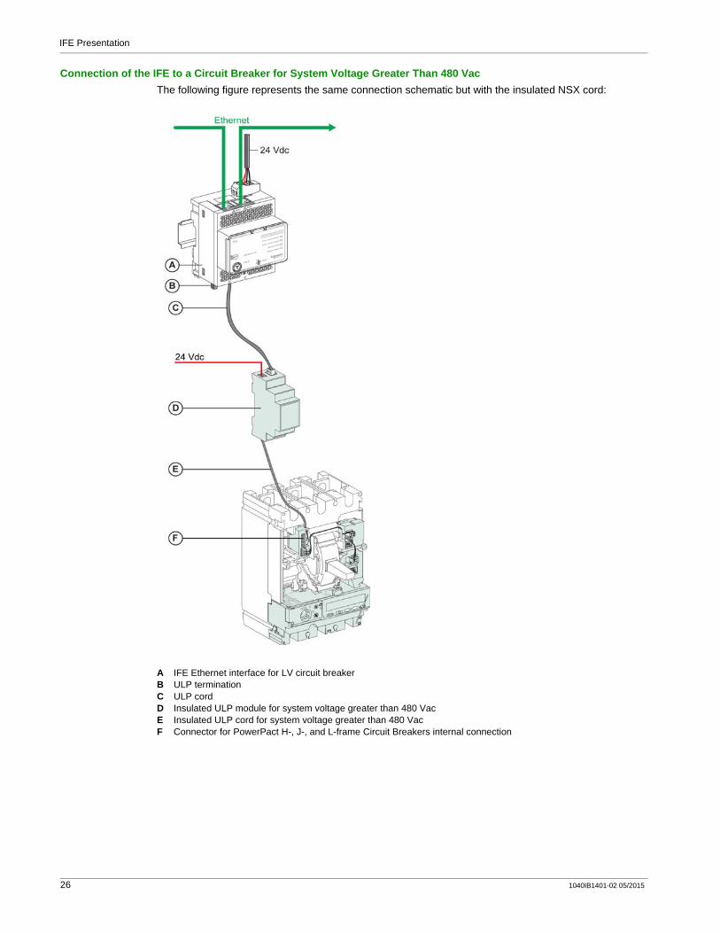
Connection of the IFE to a Circuit Breaker for System Voltage Greater Than 480 VacThe following figure represents the same connection schematic but with the insulated NSX cord:
A IFE Ethernet interface for LV circuit breakerB ULP terminationC ULP cordD Insulated ULP module for system voltage greater than 480 VacE Insulated ULP cord for system voltage greater than 480 VacF Connector for PowerPact H-, J-, and L-frame Circuit Breakers internal connection
26 1040IB1401-02 05/2015

IFE Presentation
Technical Characteristics
Environmental Characteristics
Mechanical Characteristics
Electrical Characteristics
Physical Characteristics
Characteristic Value
Conforming to standards IEC 60950IEC 60947-6-2
UL508UL60950IACS E10
Certification cULus, CE, EAC, and FCC marking
Ambient temperature Storage -40 to +85 °C (-40 to +185 °F)
Operation -25 to +70 °C (-13 to +158 °F)
Protective treatment ULV0, conforming to IEC/EN 60068-2-30
Pollution Level 3
Characteristic Value
Shock resistance Conforming to IEC 60068-2-2715 g/11 ms, 1/2 sinusoidal
Resistance to sinusoidal vibrations Conforming to IEC/EN 60068-2-6
Characteristics Value
Power supply 24 Vdc, -20%/+10% (19.2–26.4 Vdc)
Consumption Typical 24 Vdc, 120 mA at 20 °C
Maximum with gateway 19.2 Vdc, 3 A at 60 °C
Characteristic Value
Dimensions 72 x 105 x 71 mm (2.83 x 4.13 x 2.79 in)
Mounting DIN rail
Weight 182.5 g (0.41 lb)
Degree of protection of the installed module On the front panel (wall-mounted enclosure): IP4xConnectors: IP2xOther parts: IP3x
Connections Screw type terminal blocks
1040IB1401-02 05/2015 27

IFE Presentation
24 Vdc Power Supply CharacteristicsIt is recommended to use an UL listed/UL recognized limited voltage/limited current or a class 2 power supply with a 24 Vdc, 3 A maximum.
For more information, refer to the ULP System User Guide.
Characteristic Value
Power supply type Regulated switch type
Rated power 72 W
Input voltage 100–120 Vac for single phase
200–500 Vac phase-to-phase
PFC filter With IEC 61000-3-2
Output voltage 24 Vdc
Power supply output current 3 A
28 1040IB1401-02 05/2015
IFE Presentation
Firmware Update
DescriptionThe IFE consists of two component types that can be upgraded using the customer engineering tool (see page 16):
FirmwareWebpage, device supporting file, and data fileIt is recommended to use the Ecoreach software, customer engineering tool, for all firmware upgrades. Ecoreach provides a one click update option that ensures consistency between the firmware and device webpages. The following instructions also explain on how to update the webpage using FTP.
NOTE: The Ecoreach software must be used for maintaining the firmware of the device.
NOTE: Before starting the firmware upgrade take a backup of the data log files (see page 74).
NOTE: The customer engineering tool automatically downloads the latest firmware version from the Schneider Electric server.
If you add or update a device, the firmware has the potential to create inconsistencies. Hence, it is important to review your firmware upgrade plan with respect to other devices in the system. If the firmware creates inconsistencies, the system may have some limitations or unexpected behavior.
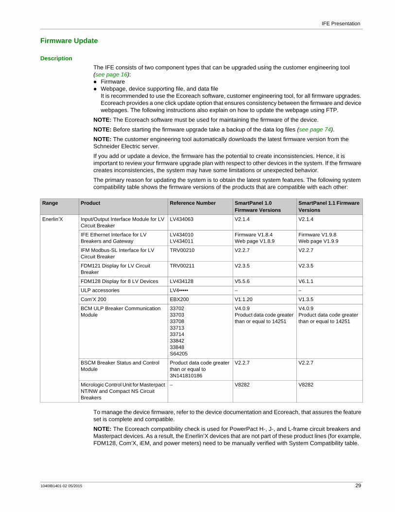
The primary reason for updating the system is to obtain the latest system features. The following system compatibility table shows the firmware versions of the products that are compatible with each other:
To manage the device firmware, refer to the device documentation and Ecoreach, that assures the feature set is complete and compatible.
NOTE: The Ecoreach compatibility check is used for PowerPact H-, J-, and L-frame circuit breakers and Masterpact devices. As a result, the Enerlin’X devices that are not part of these product lines (for example, FDM128, Com’X, iEM, and power meters) need to be manually verified with System Compatibility table.
Range Product Reference Number SmartPanel 1.0 Firmware Versions
SmartPanel 1.1 Firmware Versions
Enerlin’X Input/Output Interface Module for LV Circuit Breaker
LV434063 V2.1.4 V2.1.4
IFE Ethernet Interface for LV Breakers and Gateway
LV434010LV434011
Firmware V1.8.4Web page V1.8.9
Firmware V1.9.8Web page V1.9.9
IFM Modbus-SL Interface for LV Circuit Breaker
TRV00210 V2.2.7 V2.2.7
FDM121 Display for LV Circuit Breaker
TRV00211 V2.3.5 V2.3.5
FDM128 Display for 8 LV Devices LV434128 V5.5.6 V6.1.1
ULP accessories LV4••••• – –
Com’X 200 EBX200 V1.1.20 V1.3.5
BCM ULP Breaker Communication Module
33702337033370833713337143384233848S64205
V4.0.9Product data code greater than or equal to 14251
V4.0.9Product data code greater than or equal to 14251
BSCM Breaker Status and Control Module
Product data code greater than or equal to 3N141810186
V2.2.7 V2.2.7
Micrologic Control Unit for Masterpact NT/NW and Compact NS Circuit Breakers
– V8282 V8282
1040IB1401-02 05/2015 29
IFE Presentation
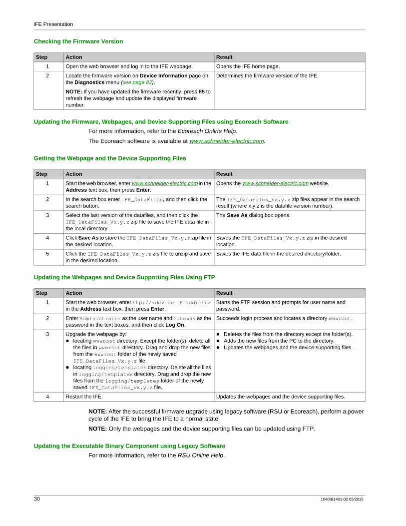
Checking the Firmware Version
Updating the Firmware, Webpages, and Device Supporting Files using Ecoreach SoftwareFor more information, refer to the Ecoreach Online Help.
The Ecoreach software is available at www.schneider-electric.com.
Getting the Webpage and the Device Supporting Files
Updating the Webpages and Device Supporting Files Using FTP
NOTE: After the successful firmware upgrade using legacy software (RSU or Ecoreach), perform a power cycle of the IFE to bring the IFE to a normal state.
NOTE: Only the webpages and the device supporting files can be updated using FTP.
Updating the Executable Binary Component using Legacy SoftwareFor more information, refer to the RSU Online Help.
Step Action Result
1 Open the web browser and log in to the IFE webpage. Opens the IFE home page.
2 Locate the firmware version on Device Information page on the Diagnostics menu (see page 82).
NOTE: If you have updated the firmware recently, press F5 to refresh the webpage and update the displayed firmware number.
Determines the firmware version of the IFE.
Step Action Result
1 Start the web browser, enter www.schneider-electric.com in the Address text box, then press Enter.
Opens the www.schneider-electric.com website.
2 In the search box enter IFE_DataFiles, and then click the search button.
The IFE_DataFiles_Vx.y.z zip files appear in the search result (where x.y.z is the datafile version number).
3 Select the last version of the datafiles, and then click the IFE_DataFiles_Vx.y.z zip file to save the IFE data file in the local directory.
The Save As dialog box opens.
4 Click Save As to store the IFE_DataFiles_Vx.y.z zip file in the desired location.
Saves the IFE_DataFiles_Vx.y.z zip in the desired location.
5 Click the IFE_DataFiles_Vx.y.z zip file to unzip and save in the desired location.
Saves the IFE data file in the desired directory/folder.
Step Action Result
1 Start the web browser, enter ftp://<device IP address> in the Address text box, then press Enter.
Starts the FTP session and prompts for user name and password.
2 Enter Administrator as the user name and Gateway as the password in the text boxes, and then click Log On.
Succeeds login process and locates a directory wwwroot.
3 Upgrade the webpage by:locating wwwroot directory. Except the folder(s), delete all the files in wwwroot directory. Drag and drop the new files from the wwwroot folder of the newly saved IFE_DataFiles_Vx.y.z file.locating logging/templates directory. Delete all the files in logging/templates directory. Drag and drop the new files from the logging/templates folder of the newly saved IFE_DataFiles_Vx.y.z file.
Deletes the files from the directory except the folder(s).Adds the new files from the PC to the directory.Updates the webpages and the device supporting files.
4 Restart the IFE. Updates the webpages and the device supporting files.
30 1040IB1401-02 05/2015
IFE Presentation
Protecting the Environment
Recycling PackagingThe packing materials from this equipment can be recycled. Please help protect the environment by recycling them in appropriate containers.
Thank you for playing your part in protecting the environment.
End-of-Life RecyclingAt the end of life, the modules of the ULP system have been optimized to decrease the amount of waste and valorize the components and materials of the product in the usual end of life treatment process.
The design has been achieved so as components are able to enter the usual end of life treatment processes as appropriate: depollution if recommended, reuse and/or dismantling if recommended so as to increase the recycling performances and shredding for separating the rest of materials.
1040IB1401-02 05/2015 31

IFE Presentation
32 1040IB1401-02 05/2015
IFE Ethernet Interface for LV Circuit BreakerIFE Web Server1040IB1401-02 05/2015
IFE Web Server
Chapter 2IFE Web Server
What Is in This Chapter?This chapter contains the following sections:
Section Topic Page
2.1 IFE Ethernet Interface for LV Circuit Breaker 34
2.2 IFE Web Server - Configuration & Settings Pages 42
2.3 IFE Web Server - Monitoring Pages 70
2.4 IFE Web Server - Control Page 77
2.5 IFE Web Server - Diagnostics Pages 79
2.6 IFE Web Server - Maintenance Pages 87
1040IB1401-02 05/2015 33
IFE Web Server
IFE Ethernet Interface for LV Circuit Breaker
Section 2.1IFE Ethernet Interface for LV Circuit Breaker
What Is in This Section?This section contains the following topics:
Topic Page
Access to IFE Webpages 35
User Interface Layout 38
Webpage Description 40
34 1040IB1401-02 05/2015
IFE Web Server
Access to IFE Webpages
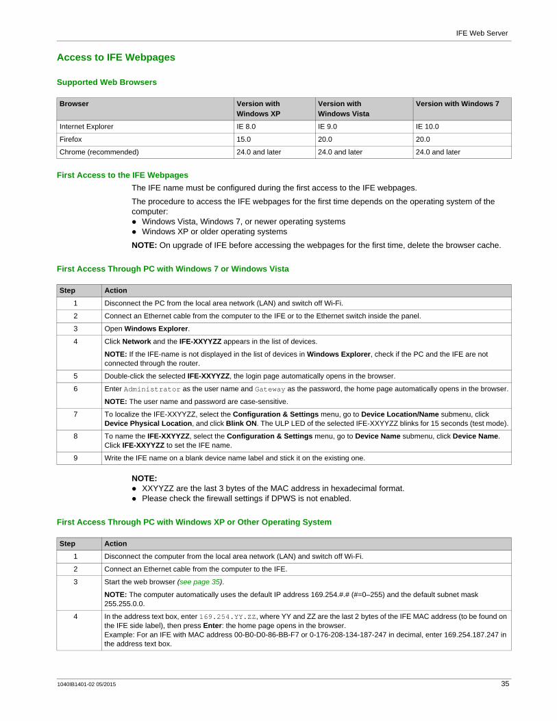
Supported Web Browsers
First Access to the IFE WebpagesThe IFE name must be configured during the first access to the IFE webpages.
The procedure to access the IFE webpages for the first time depends on the operating system of the computer:
Windows Vista, Windows 7, or newer operating systemsWindows XP or older operating systems
NOTE: On upgrade of IFE before accessing the webpages for the first time, delete the browser cache.
First Access Through PC with Windows 7 or Windows Vista
NOTE: XXYYZZ are the last 3 bytes of the MAC address in hexadecimal format.Please check the firewall settings if DPWS is not enabled.
First Access Through PC with Windows XP or Other Operating System
Browser Version with Windows XP
Version with Windows Vista
Version with Windows 7
Internet Explorer IE 8.0 IE 9.0 IE 10.0
Firefox 15.0 20.0 20.0
Chrome (recommended) 24.0 and later 24.0 and later 24.0 and later
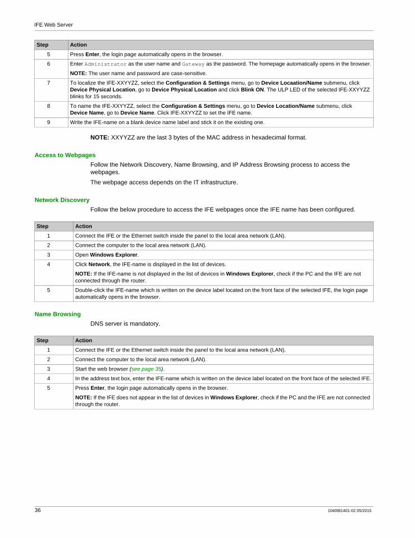
Step Action
1 Disconnect the PC from the local area network (LAN) and switch off Wi-Fi.
2 Connect an Ethernet cable from the computer to the IFE or to the Ethernet switch inside the panel.
3 Open Windows Explorer.
4 Click Network and the IFE-XXYYZZ appears in the list of devices.
NOTE: If the IFE-name is not displayed in the list of devices in Windows Explorer, check if the PC and the IFE are not connected through the router.
5 Double-click the selected IFE-XXYYZZ, the login page automatically opens in the browser.
6 Enter Administrator as the user name and Gateway as the password, the home page automatically opens in the browser.
NOTE: The user name and password are case-sensitive.
7 To localize the IFE-XXYYZZ, select the Configuration & Settings menu, go to Device Location/Name submenu, click Device Physical Location, and click Blink ON. The ULP LED of the selected IFE-XXYYZZ blinks for 15 seconds (test mode).
8 To name the IFE-XXYYZZ, select the Configuration & Settings menu, go to Device Name submenu, click Device Name. Click IFE-XXYYZZ to set the IFE name.
9 Write the IFE name on a blank device name label and stick it on the existing one.
Step Action
1 Disconnect the computer from the local area network (LAN) and switch off Wi-Fi.
2 Connect an Ethernet cable from the computer to the IFE.
3 Start the web browser (see page 35).
NOTE: The computer automatically uses the default IP address 169.254.#.# (#=0–255) and the default subnet mask 255.255.0.0.
4 In the address text box, enter 169.254.YY.ZZ, where YY and ZZ are the last 2 bytes of the IFE MAC address (to be found on the IFE side label), then press Enter: the home page opens in the browser.Example: For an IFE with MAC address 00-B0-D0-86-BB-F7 or 0-176-208-134-187-247 in decimal, enter 169.254.187.247 in the address text box.
1040IB1401-02 05/2015 35
IFE Web Server
NOTE: XXYYZZ are the last 3 bytes of the MAC address in hexadecimal format.
Access to WebpagesFollow the Network Discovery, Name Browsing, and IP Address Browsing process to access the webpages.
The webpage access depends on the IT infrastructure.
Network DiscoveryFollow the below procedure to access the IFE webpages once the IFE name has been configured.
Name BrowsingDNS server is mandatory.
5 Press Enter, the login page automatically opens in the browser.
6 Enter Administrator as the user name and Gateway as the password. The homepage automatically opens in the browser.
NOTE: The user name and password are case-sensitive.
7 To localize the IFE-XXYYZZ, select the Configuration & Settings menu, go to Device Locaation/Name submenu, click Device Physical Location, go to Device Physical Location and click Blink ON. The ULP LED of the selected IFE-XXYYZZ blinks for 15 seconds.
8 To name the IFE-XXYYZZ, select the Configuration & Settings menu, go to Device Location/Name submenu, click Device Name, go to Device Name. Click IFE-XXYYZZ to set the IFE name.
9 Write the IFE-name on a blank device name label and stick it on the existing one.
Step Action
Step Action
1 Connect the IFE or the Ethernet switch inside the panel to the local area network (LAN).
2 Connect the computer to the local area network (LAN).
3 Open Windows Explorer.
4 Click Network, the IFE-name is displayed in the list of devices.
NOTE: If the IFE-name is not displayed in the list of devices in Windows Explorer, check if the PC and the IFE are not connected through the router.
5 Double-click the IFE-name which is written on the device label located on the front face of the selected IFE, the login page automatically opens in the browser.
Step Action
1 Connect the IFE or the Ethernet switch inside the panel to the local area network (LAN).
2 Connect the computer to the local area network (LAN).
3 Start the web browser (see page 35).
4 In the address text box, enter the IFE-name which is written on the device label located on the front face of the selected IFE.
5 Press Enter, the login page automatically opens in the browser.
NOTE: If the IFE does not appear in the list of devices in Windows Explorer, check if the PC and the IFE are not connected through the router.
36 1040IB1401-02 05/2015

IFE Web Server
IP Address BrowsingIP static configuration has to be set.
First Time Log InThe web browser is a tool for reading and writing data. It is recommended to change the default password during the first-time login to prevent unauthorized access.
NOTE: The password should not be shared or distributed to unauthorized personnel. The password should not contain any personal or obvious information.
Step Action
1 Connect the IFE or the Ethernet switch inside the panel to the local area network (LAN).
2 Connect the computer to the local area network (LAN).
3 Start the web browser (see page 35).
4 In the address text box, enter IP address given by the IT administrator.
5 Press Enter, the login page automatically opens in the browser.
NOTE: If the login page in the web browser does not open or does not display correctly, check if Internet Explorer\Tools\Compatibility View Settings\Display Intranet sites in Compatibility View in Internet Explorer is checked.
WARNINGUNAUTHORIZED DATA ACCESS
Immediately change the default password to a new and secure password.DO NOT distribute the password to unauthorized or otherwise unqualified personnel.
Failure to follow these instructions can result in death, serious injury, or equipment damage.
1040IB1401-02 05/2015 37
IFE Web Server
User Interface Layout
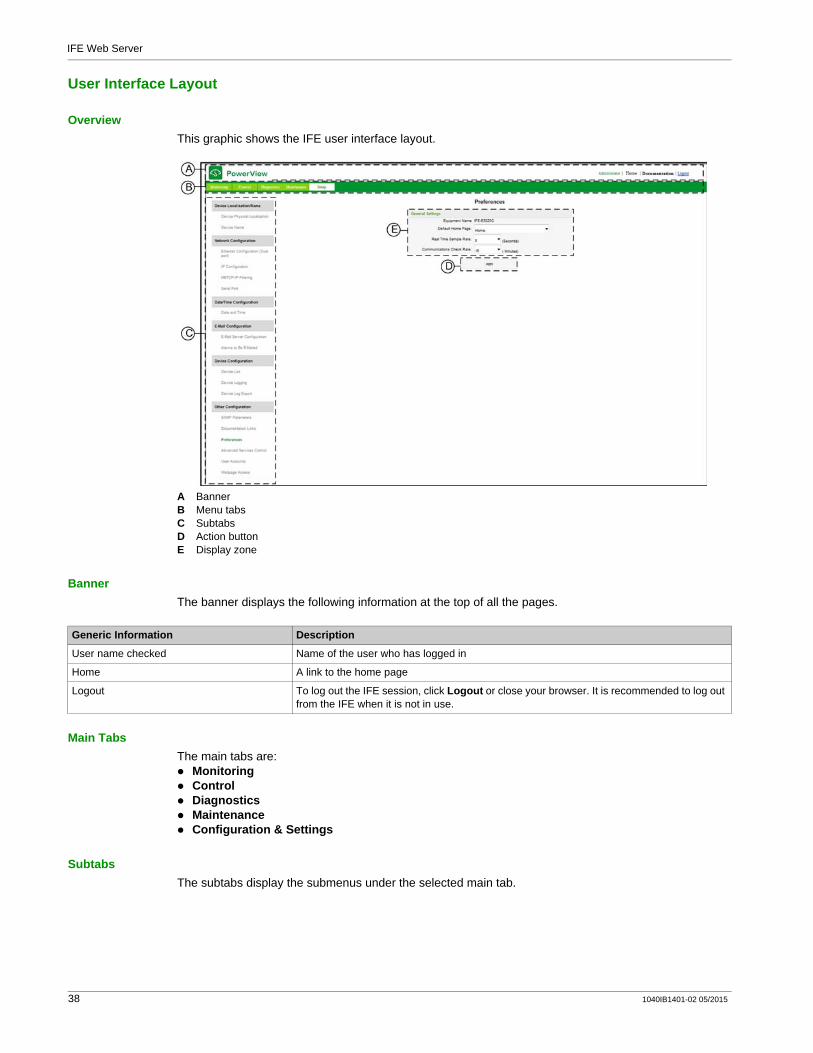
OverviewThis graphic shows the IFE user interface layout.
A BannerB Menu tabsC SubtabsD Action buttonE Display zone
BannerThe banner displays the following information at the top of all the pages.
Main TabsThe main tabs are:
MonitoringControlDiagnosticsMaintenanceConfiguration & Settings
SubtabsThe subtabs display the submenus under the selected main tab.
Generic Information Description
User name checked Name of the user who has logged in
Home A link to the home page
Logout To log out the IFE session, click Logout or close your browser. It is recommended to log out from the IFE when it is not in use.
38 1040IB1401-02 05/2015

IFE Web Server
Action ButtonsThe action buttons correspond to the selected tab and it varies.
The following table describes the interface buttons:
Display ZoneThe display zone shows the selected subtab in detail with all the related fields.
Button Action
Save changes Validates the modification.
Apply Applies the changes.
Cancel Cancels the modifications to return to the last saved settings.
1040IB1401-02 05/2015 39
IFE Web Server
Webpage Description
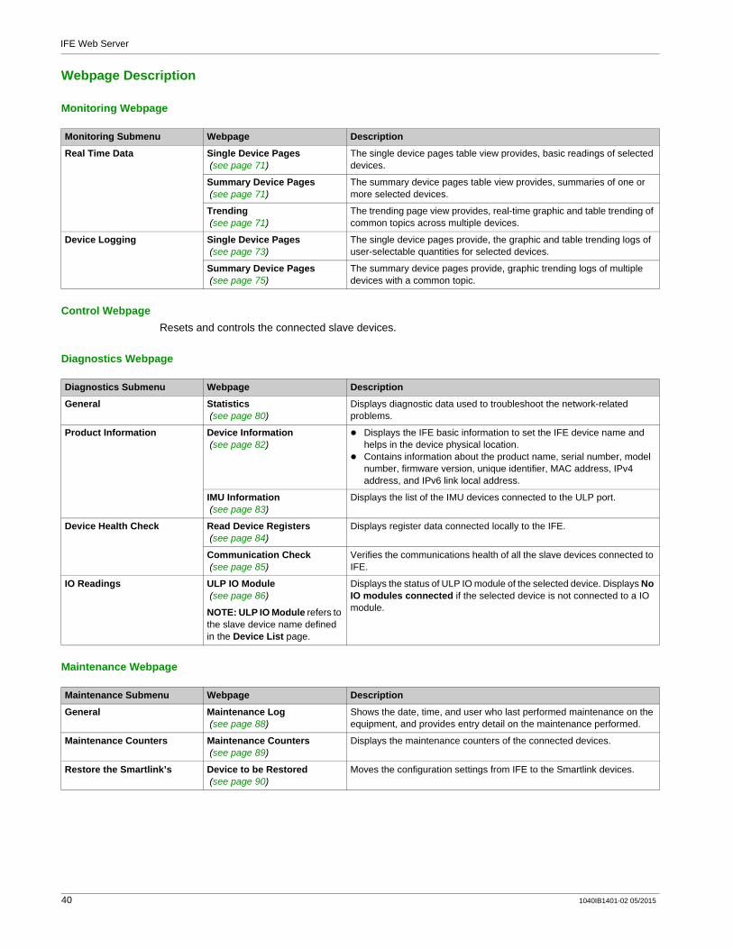
Monitoring Webpage
Control WebpageResets and controls the connected slave devices.
Diagnostics Webpage
Maintenance Webpage
Monitoring Submenu Webpage Description
Real Time Data Single Device Pages (see page 71)
The single device pages table view provides, basic readings of selected devices.
Summary Device Pages (see page 71)
The summary device pages table view provides, summaries of one or more selected devices.
Trending (see page 71)
The trending page view provides, real-time graphic and table trending of common topics across multiple devices.
Device Logging Single Device Pages (see page 73)
The single device pages provide, the graphic and table trending logs of user-selectable quantities for selected devices.
Summary Device Pages (see page 75)
The summary device pages provide, graphic trending logs of multiple devices with a common topic.
Diagnostics Submenu Webpage Description
General Statistics (see page 80)
Displays diagnostic data used to troubleshoot the network-related problems.
Product Information Device Information (see page 82)
Displays the IFE basic information to set the IFE device name and helps in the device physical location.Contains information about the product name, serial number, model number, firmware version, unique identifier, MAC address, IPv4 address, and IPv6 link local address.
IMU Information (see page 83)
Displays the list of the IMU devices connected to the ULP port.
Device Health Check Read Device Registers (see page 84)
Displays register data connected locally to the IFE.
Communication Check (see page 85)
Verifies the communications health of all the slave devices connected to IFE.
IO Readings ULP IO Module (see page 86)
NOTE: ULP IO Module refers to the slave device name defined in the Device List page.
Displays the status of ULP IO module of the selected device. Displays No IO modules connected if the selected device is not connected to a IO module.
Maintenance Submenu Webpage Description
General Maintenance Log (see page 88)
Shows the date, time, and user who last performed maintenance on the equipment, and provides entry detail on the maintenance performed.
Maintenance Counters Maintenance Counters (see page 89)
Displays the maintenance counters of the connected devices.
Restore the Smartlink’s Device to be Restored (see page 90)
Moves the configuration settings from IFE to the Smartlink devices.
40 1040IB1401-02 05/2015

IFE Web Server
Configuration & Settings Webpage
Configuration & Settings Submenu
Webpage Description
Device Location/Name Device Physical Location (see page 43)
Localizes the device IFE-XXYYZZClick Blink ON.The ULP LED of the selected device IFE-XXYYZZ blinks and is active for 15 s (Test mode: 1 s ON, 1 s OFF).
Device Name (see page 44)
Configures the IFE device name
Network Configuration Ethernet Configuration (Dual port) (see page 45)
Configures the Ethernet.
IP Configuration (see page 46)
Configures the IP parameters.
Modbus TCP/IP Filtering (see page 48)
Configures the maximum number of Modbus TCP/IP server connections. Configures the IP addresses that can access the IFE through Modbus TCP/IP.
Serial Port (see page 49)
Configures serial communication parameters.
Date/Time Configuration Date and Time (see page 50)
Sets the date and time manually.
Email Configuration Email Server Configuration (see page 51)
Configures the alarms to be emailed.Configures the SMTP parameter for mailing purpose.
Alarms to Email (see page 53)
Configures the alarms to be sent through email.
Device Configuration Device List (see page 56)
Configures local serial devices on the Modbus serial daisy chain and IMU core product connected to the ULP port.
Device Logging (see page 61)
Configures device logging parameters.
Device Log Export (see page 63)
Configures device logging export options.
Other Configuration SNMP Parameters (see page 64)
Configures Simple Network Management Protocol (SNMP).
Documentation Links (see page 65)
Configures file and URL documentation links.
Preferences (see page 66)
Configures IFE preferences.
Advanced Services Control (see page 67)
Configures the advanced service control parameters.
User Account (see page 68)
Creates and edits groups and users. Configures email accounts.
Webpage Access (see page 69)
Configures webpage access rights for each user group.
1040IB1401-02 05/2015 41
IFE Web Server
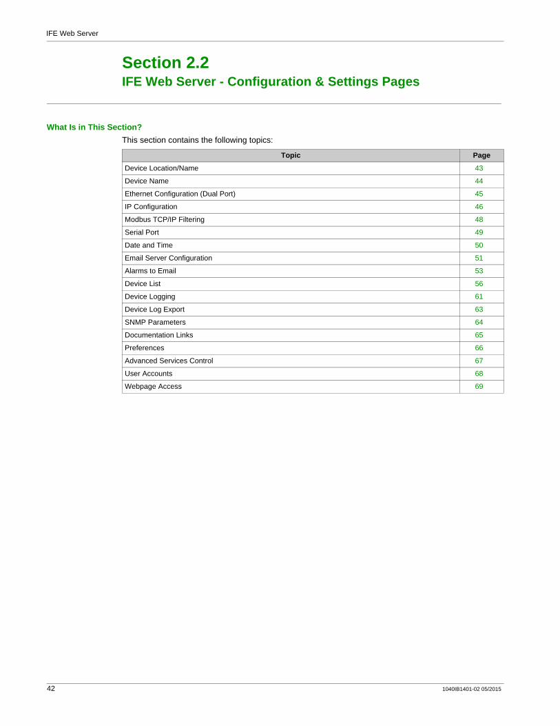
IFE Web Server - Configuration & Settings Pages
Section 2.2IFE Web Server - Configuration & Settings Pages
What Is in This Section?This section contains the following topics:
Topic Page
Device Location/Name 43
Device Name 44
Ethernet Configuration (Dual Port) 45
IP Configuration 46
Modbus TCP/IP Filtering 48
Serial Port 49
Date and Time 50
Email Server Configuration 51
Alarms to Email 53
Device List 56
Device Logging 61
Device Log Export 63
SNMP Parameters 64
Documentation Links 65
Preferences 66
Advanced Services Control 67
User Accounts 68
Webpage Access 69
42 1040IB1401-02 05/2015
IFE Web Server
Device Location/Name
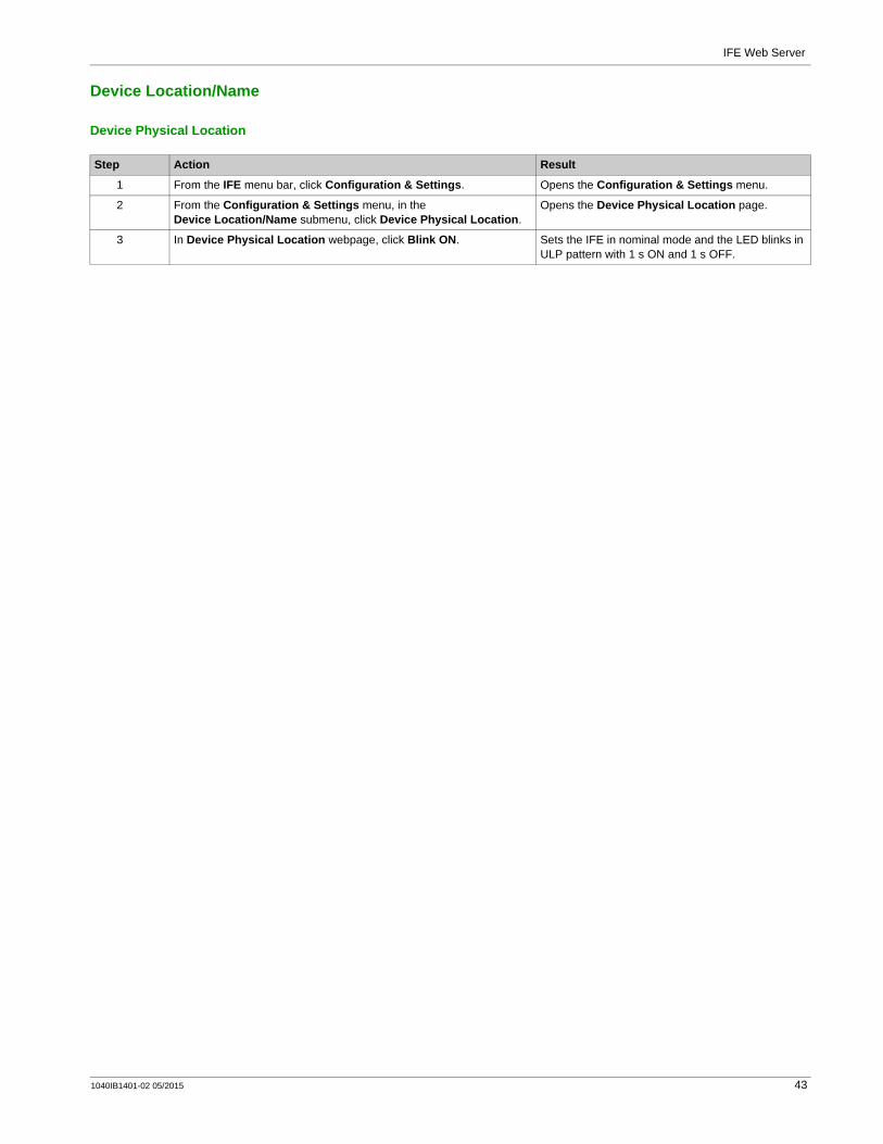
Device Physical Location
Step Action Result
1 From the IFE menu bar, click Configuration & Settings. Opens the Configuration & Settings menu.
2 From the Configuration & Settings menu, in the Device Location/Name submenu, click Device Physical Location.
Opens the Device Physical Location page.
3 In Device Physical Location webpage, click Blink ON. Sets the IFE in nominal mode and the LED blinks in ULP pattern with 1 s ON and 1 s OFF.
1040IB1401-02 05/2015 43

IFE Web Server
Device Name
Device Name Configuration
Step Action Result
1 From the IFE menu bar, click Configuration & Settings. Opens the Configuration & Settings menu.
2 From the Configuration & Settings menu, in the Device Location/Name submenu, click Device Name.
Opens the Device Name page.
3 In Device Name Configuration webpage, enter the device name and click Apply.
Sets the IFE in test mode and the ULP LED blinks with 1 s ON and 1 s OFF.
44 1040IB1401-02 05/2015

IFE Web Server
Ethernet Configuration (Dual Port)
Ethernet
Ethernet Port Control
Broadcast Storm Protection
Parameter Description Settings
MAC address A unique media access control address of an IFE. The MAC address is written on the label which is placed on the side of the IFE.
–
Frame format Used to select the format for data sent over an Ethernet connection.
Ethernet II802.3Auto (Factory setting)
Parameter Description Settings
Speed and mode for Port #1 Used to define the physical Ethernet connection speed and transmission mode for Ethernet port 1.
Auto-negotiation (Factory setting)
Speed and mode for Port #2 Used to define the physical Ethernet connection speed and transmission for Ethernet port 2.
Auto-negotiation (Factory setting)
Parameter Description Settings
Level Defines the storm protection level. The level value corresponds to a committed information rate (CIR) value, that is, the amount of traffic entering the switch port from which the storm protection drops entering the broadcast traffic.
NOTE: If the level value is changed, you are prompted to restart the device to implement changes.
01234 (Factory setting)56
Committed Information Rate Defines the read-only value of the storm protection level. –
1040IB1401-02 05/2015 45

IFE Web Server
IP Configuration
IPv4 Configuration
IPv6 Configuration
DNS
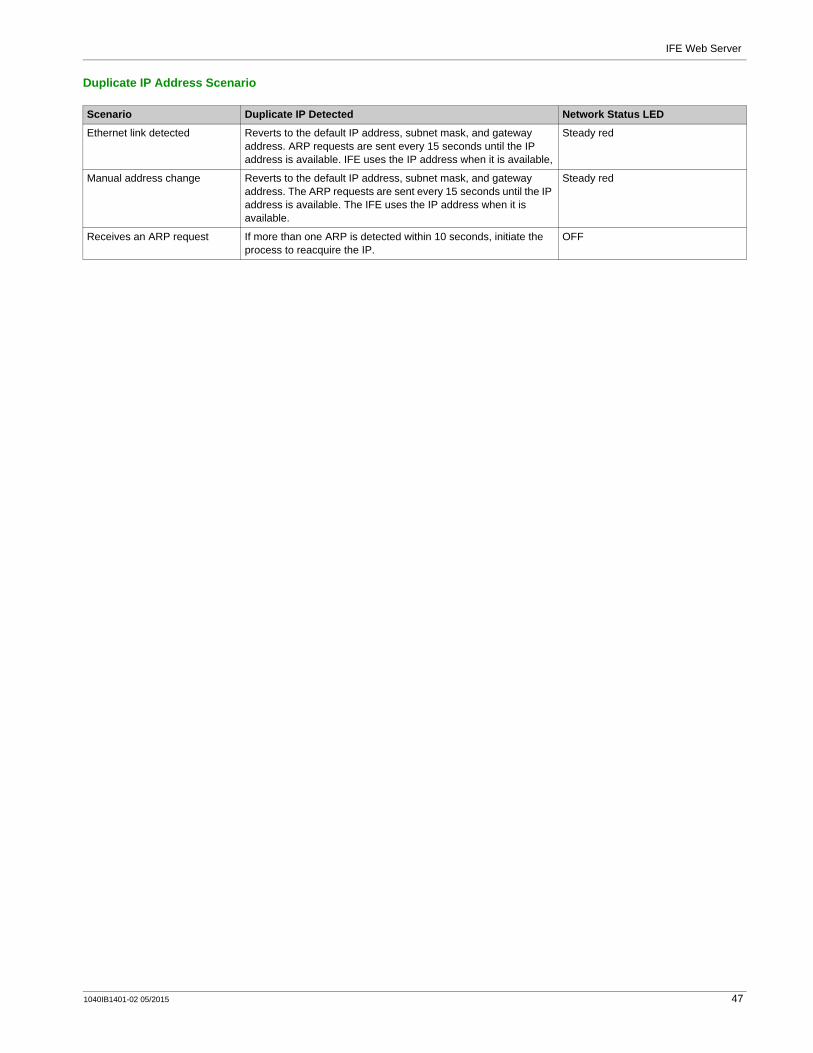
Duplicate IP Address DetectionWhile connected to your network, the IFE publishes its IP address. To avoid any duplicate IP address conflicts, the IFE uses the address resolution protocol (ARP) to see if any other device on your network is using the same IP address. The below table explains how the IFE handles a duplicate IP address when it is detected.
Parameter Description Settings
Obtain an IP address automatically using
Used to select the mode for assigning the IPv4 parameters set. Obtain IPv4 parameters automatically using BOOTP or DHCP.
NOTE: While using a DHCP server, the device name must be limited to 16 characters.
DHCP (Factory setting)BOOTP
Manual IP address Used to enter the static IP address of an IFE.
169.254.X.Y (Factory setting)
NOTE: X and Y are the last 2 bytes of the IFE MAC address (which is found on the IFE label).
Manual Subnet mask Used to enter the Ethernet IP subnet mask address of your network.
255.255.0.0 (Factory setting)
Manual Default gateway Used to enter the gateway (router) IP address used for wide area network (WAN) communication.
169.254.2.1 (Factory setting)Factory setting of gateway is same as the default IP address of the IFE.
Parameter Description Settings
Enable IPv6 Defines the IPv6 configuration. Enabled (Factory setting)
NOTE: The setting is unavailable to edit.
Link local address Used to open the IFE webpage for future use.
NOTE: In the URL address box, use [ ] brackets to enter the link local address.
–
Parameter Description Setting
Obtain DNS address automatically Defines the dynamic behavior of the DNS server address configuration. Used to obtain the IP address from the DNS server automatically.
NOTE: Domain name system (DNS) is the naming system for computers and devices connected to a local area network (LAN) or the Internet.
Disabled when manual setting is selected.
Manual Primary server address Defines the IPv4 address of the primary DNS server. –
Manual Secondary server address Defines the IPv4 address of the secondary DNS server. Used to perform a DNS resolution when the resolution fails with the primary DNS server.
–
46 1040IB1401-02 05/2015
IFE Web Server
Duplicate IP Address Scenario
Scenario Duplicate IP Detected Network Status LED
Ethernet link detected Reverts to the default IP address, subnet mask, and gateway address. ARP requests are sent every 15 seconds until the IP address is available. IFE uses the IP address when it is available,
Steady red
Manual address change Reverts to the default IP address, subnet mask, and gateway address. The ARP requests are sent every 15 seconds until the IP address is available. The IFE uses the IP address when it is available.
Steady red
Receives an ARP request If more than one ARP is detected within 10 seconds, initiate the process to reacquire the IP.
OFF
1040IB1401-02 05/2015 47

IFE Web Server
Modbus TCP/IP Filtering
DescriptionThis page allows you to define the level of access for Modbus TCP/IP clients connected to IFE.
Block ConnectionsYou can select the maximum number of IP connections allowed, 8 or 16.
NOTE: When the maximum number of IP connections is changed, a message pops-up on the screen Max Connection is changed. Restart the Device to Take Effect and prompts to restart the device.
IP Filtering
Parameter Description Setting
Enable IP_Filtering Activates the IP address filtering. The list of IP addresses available in the table is granted access.
EnabledDisabled (No filtering)
Address Filters the required IP address entered by you. 10 addresses (Maximum allowed IP addresses)
Accessibility Defines the access level for the corresponding IP address.
Read: The following Modbus TCP/IP function codes are allowed:
1 (0x01)2 (0x02)3 (0x03)4 (0x04)7 (0x07)8 (0x08)11 (0x0B)12 (0x0C)17 (0x11)20 (0x14)24 (0x18)43 (0x2B), with subfunction codes 14 (0x0E), 15 (0x0F), and 16 (0x10).100 (0x64)
None: The access to the IP address is blocked.Read/Write: Full access is provided.
Allow Anonymous IP Allows all Modbus TCP/IP clients to have the read-only access.
EnabledDisabled (Factory setting)
48 1040IB1401-02 05/2015

IFE Web Server
Serial Port
Serial Port Settings
NOTE: When Stop bits parameter is set to Auto, the actual value is based on the parity chosen.
Parameter Settings
Baud Rate 9600 bps19200 bps (Factory setting)38400 bps
Parity Even (Factory setting)OddNone
Stop bits Auto (Factory setting)1 bit2 bits
Termination EnabledDisabled (Factory setting)
Response Timeout 1 s (Factory setting)0.1–0.5 s1–10 s
1040IB1401-02 05/2015 49
IFE Web Server
Date and Time
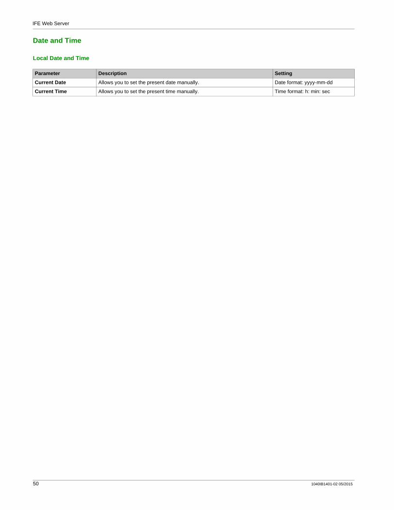
Local Date and Time
Parameter Description Setting
Current Date Allows you to set the present date manually. Date format: yyyy-mm-dd
Current Time Allows you to set the present time manually. Time format: h: min: sec
50 1040IB1401-02 05/2015
IFE Web Server
Email Server Configuration
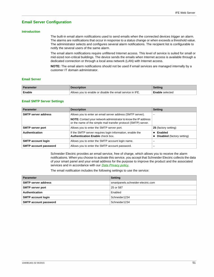
IntroductionThe built-in email alarm notifications used to send emails when the connected devices trigger an alarm. The alarms are notifications that occur in response to a status change or when exceeds a threshold value. The administrator selects and configures several alarm notifications. The recipient list is configurable to notify the several users of the same alarm.
The email alarm notifications require unfiltered Internet access. This level of service is suited for small or mid-sized non-critical buildings. The device sends the emails when Internet access is available through a dedicated connection or through a local area network (LAN) with Internet access.
NOTE: The email alarm notifications should not be used if email services are managed internally by a customer IT domain administrator.
Email Server
Email SMTP Server Settings
Schneider Electric provides an email service, free of charge, which allows you to receive the alarm notifications. When you choose to activate this service, you accept that Schneider Electric collects the data of your smart panel and your email address for the purpose to improve the product and the associated services and in accordance with our Data Privacy policy.
The email notification includes the following settings to use the service:
Parameter Description Setting
Enable Allows you to enable or disable the email service in IFE. Enable selected
Parameter Description Setting
SMTP server address Allows you to enter an email server address (SMTP server).
NOTE: Contact your network administrator to know the IP address or the name of the simple mail transfer protocol (SMTP) server.
–
SMTP server port Allows you to enter the SMTP server port. 25 (factory setting)
Authentication If the SMTP server requires login information, enable the Authentication Enable check box.
EnabledDisabled (factory setting)
SMTP account login Allows you to enter the SMTP account login name. –
SMTP account password Allows you to enter the SMTP account password. –
Parameter Setting
SMTP server address smartpanels.schneider-electric.com
SMTP server port 25 or 587
Authentication Enabled
SMTP account login Schneider1234
SMTP account password Schneider1234
1040IB1401-02 05/2015 51

IFE Web Server
Email Sender Address
The From address can be used in different ways:Use the From address as context provider: If you want to be only notified without a reply, use a From address as contextual information. The From address syntax includes “no-reply”, “device name”, “site name”, @a validated domain .com, .net, and so on.Create an alias in the From address to allow replies to be sent to the person in charge of an alarm: An email can be sent to multiple people who are responsible for a specific appliance. This feature allows the receivers to reply to follow up with the responsible person.For example, the facility manager would receive an email from an alarm. Facility manager can send a reply email to the maintenance contractor to follow up on the action.
Email Language
Email Test
The Email Test feature enables connection from the device to the service. If the test emails are not received, the Internet connection needs to enable the email ports (port 25 or 587). The required setting of the port is done in accordance between the device that sends the email and the site router settings.
NOTE: The email with custom text that uses characters such as à, è, ù, é, â, ê, î, ô, û , ë, ï, ü, ÿ, and ç are not shown correctly in the email but the generic text message is shown correctly.
Parameter Description Setting
From address In the From Address box, enter the email address of the administrator who is administering the device.
–
Parameter Description Setting
Language Allows you to select the language of the email body. English (factory setting)French
Parameter Description Setting
Recipient address for test Allows you to enter the email address of the recipient to test the delivery of the email.
–
52 1040IB1401-02 05/2015
IFE Web Server
Alarms to Email
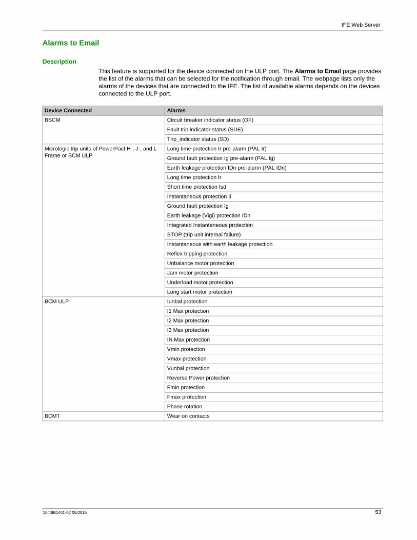
DescriptionThis feature is supported for the device connected on the ULP port. The Alarms to Email page provides the list of the alarms that can be selected for the notification through email. The webpage lists only the alarms of the devices that are connected to the IFE. The list of available alarms depends on the devices connected to the ULP port.
Device Connected Alarms
BSCM Circuit breaker indicator status (OF)
Fault trip indicator status (SDE)
Trip_indicator status (SD)
Micrologic trip units of PowerPact H-, J-, and L-Frame or BCM ULP
Long time protection Ir pre-alarm (PAL Ir)
Ground fault protection Ig pre-alarm (PAL Ig)
Earth leakage protection IDn pre-alarm (PAL IDn)
Long time protection Ir
Short time protection Isd
Instantaneous protection Ii
Ground fault protection Ig
Earth leakage (Vigi) protection IDn
Integrated Instantaneous protection
STOP (trip unit internal failure)
Instantaneous with earth leakage protection
Reflex tripping protection
Unbalance motor protection
Jam motor protection
Underload motor protection
Long start motor protection
BCM ULP Iunbal protection
I1 Max protection
I2 Max protection
I3 Max protection
IN Max protection
Vmin protection
Vmax protection
Vunbal protection
Reverse Power protection
Fmin protection
Fmax protection
Phase rotation
BCMT Wear on contacts
1040IB1401-02 05/2015 53

IFE Web Server
IO module 1 Switchboard Temperature threshold 1(#1)
Switchboard Temperature threshold 2(#1)
Switchboard Temperature threshold 3(#1)
Threshold overrun on Input 1 counter(#1)
Threshold overrun on Input 2 counter(#1)
Threshold overrun on Input 3 counter(#1)
Threshold overrun on Input 4 counter(#1)
Threshold overrun on Input 5 counter(#1)
Threshold overrun on Input 6 counter(#1)
IO module 2 Switchboard Temperature threshold 1(#2)
Switchboard Temperature threshold 2(#2)
Switchboard Temperature threshold 3(#2)
Threshold overrun on Input 1 counter(#2)
Threshold overrun on Input 2 counter(#2)
Threshold overrun on Input 3 counter(#2)
Threshold overrun on Input 4 counter(#2)
Threshold overrun on Input 5 counter(#2)
Threshold overrun on Input 6 counter(#2)
IO module 1 or IO module 2 IO module in STOP mode (internal failure)
IO module in Error mode (internal failure)
Remove device from cradle and put it back
Regrease cradle and disconnecting-contact
Cradle replacement must be performed within 6 months
new Micrologic unit has been detected
SwitchBoard Temperature Contact Alarm
SwitchBoard Ventilation Contact Alarm
Earth leakage trip signal contact (SDV) alarm
Control voltage presence contact alarm
Surge protection status contact alarm
Surge failure contact alarm
Switch dis-connector ON/OFF indication alarm contact (OF)
Fuse blown indication contact alarm
Emergency Stop alarm
Energy Reduction Maintenance Setting engaged
Discrepancy with ERMS orders
Micrologic trip units of PowerPact H-, J-, and L-Frame
User-defined alarm 1
User-defined alarm 2
User-defined alarm 3
User-defined alarm 4
User-defined alarm 5
User-defined alarm 6
User-defined alarm 7
User-defined alarm 8
User-defined alarm 9
User-defined alarm 10
Device Connected Alarms
54 1040IB1401-02 05/2015

IFE Web Server
NOTE: If an email SMTP server is not located on the same Ethernet network segment as IFE, ensure that the IFE default gateway is properly configured.
Parameter Description
Alarms List of alarms for configuration
Notification A check box to enable the notification.
To-Recipients Allows you to choose from a list of email recipients.
Custom-Text Allows you to enter a custom text.
1040IB1401-02 05/2015 55

IFE Web Server
Device List
DescriptionThe device list is used to define the list of devices connected to the IFE (ULP port, serial port) and remote Modbus slave devices. In the device list, you can add, delete and/or discover devices. A maximum of 20 slave devices can be added in the device list. Under each master IFE or remote device maximum of 12 devices can be added.
The list of connected device is defined:Either automatically, using the device discovery procedureOr manually, by adding the devices one by one.
NOTE: The webpages are supported only for the devices added in the device list.
NOTE: If there are Acti9 serial devices configured using IFE with firmware v1.8.4 and IFE is upgraded to newer version then on the click of Device List the message There are some Acti 9 serial devices to be restored. Click 'OK' if you want to restore them Now. Click 'Cancel' if you want to delete the saved configuration and proceed to device list appears on the screen.
When you click OK the Maintenance page appears where the configuration of the smartlink device can be performed.The access to the Device list page is available only if all the Acti 9 smartlink devices configuration is restored or if you click Cancel.
Device List Parameters
Parameters Description Settings
IP Address Displays the device IP address.For master IFE: The IP Address box is unavailable to edit.For remote device: Allows you to enter IP address in the IP Address box.
–
Gateway Indicates if the IP device is a gateway or not.For master IFE: The Gateway check box is unavailable.For remote device: Allows you to add/discover the slave devices of remote device when you select the Gateway check box.
Gateway check box is always selected for IFE with part number LV434011Gateway check box is always cleared for IFE with part number LV434010
Address Displays the Modbus slave address of the master IFE and the remote device.
For master IFE: The Address box is unavailable to edit.For remote device: Allows you to enter the Modbus slave address of the remote device in the Address box.
For master IFE: 255 (fixed)For remote device: (1–247 or 255)
Name Allows you to enter the names for IFE and remote device. –
Connection Displays the connection type. It is unavailable to edit.
NOTE: Connection list appears only for Master IFE slave devices.
The 2 types of port are:ULP portSerial port (available for part number LV434011)
Device Type Allows you to select the slave devices from the list of supported devices (see page 93).
–
Device Name Allows you to enter the name for the discovered devices.For ULP port: Click edit, and then click Device Name to edit the device name,For Serial port, remote device, and its slaves: Click Device Name to edit the device name.
NOTE: Delete and edit operations are not allowed if the device is selected for logging.
–
Slave ID Displays the local address of the device connected to the master IFE or remote device.
For ULP port: 255 (Fixed)For Serial port and remote device: 1–247
Add Remote Devices Allows you to add remote devices. –
Apply Allows you to save device list configuration. –
56 1040IB1401-02 05/2015

IFE Web Server
Adding Device to the Device List for the First Time
Device Discovery ProcedureWhen you start device discovery, the IFE queries the ULP port, serial port, and Ethernet port using a user-defined address range. Modbus RTU protocol is used for discovery on the serial port. If the device replies to the query, the local ID is set to the current discovery address, and the device is given a default device name. The IFE, then tries to identify the device type. If the IFE recognizes the device type of the discovered device, the IFE sets the recognized device type in the Device Type field. If the IFE does not recognize the Device Type of the discovered device, the IFE sets to Modbus in the Device Type field.
The list of devices supported by the IFE is in Appendix (see page 93).
The table shows the steps to add device using device discovery procedure:
Delete Allows you to delete the selected slave devices.
NOTE: Delete operation is not allowed if the device is selected for logging.
–
Discover Allows you to discover the slave devices.
NOTE: The Discover button for the remote device is available only if you click the Apply button.
–
Allows you to add a new slave device to the device list. –
Delete Remote Device Allows you to delete the remote device.
NOTE: Delete operation is not allowed if the device is selected for logging.
–
Parameters Description Settings
Step Action Result
1 Slave device to master IFE:Add the Master IFE slave device manually (see page 58) or by device discovery (see page 57).
Adds the slave device to master IFE.
2 Remote device:In the Device List page, click Add Remote Devices to add a remote device.
Adds the remote device in the Device List page.
3 Slave device to remote device:Add the slave device for remote device by device discovery.
NOTE: The Discover button for the remote device is available only if you click the Apply button.
Adds the slave device to remote device.
4 Repeat step 2 and 3 to add more remote devices to Device List page.Click Apply to save the modified changes.
–
Step Action Result
1 From the IFE menu bar, click Configuration & Settings. Opens the Configuration & Settings menu.
2 From the Configuration & Settings menu, in the Device Configuration submenu, click Device List .
Opens the Device List page.
3 To discover locally connected devices, click Discover. Opens the Device Discovery page.
4 Enter Start Modbus ID and Stop Modbus ID. Enters the discovery address range.
5 Click Start Discover. (Click Stop Discover to stop the process).
NOTE: Discovery only finds local serial Modbus devices connected to the IFE. The device on the ULP port is discovered automatically.
Begins to discover all connected devices.
6 Enter a new device name in the Name text box. Renames the device.
7 Select the Save check box for the device to be saved in the device list. Selects or deselects a device entry to be saved or removed.
8 Click Apply in the Device Discovery page. Displays the saved device list.
1040IB1401-02 05/2015 57

IFE Web Server
Device Discovery Parameters
Adding a Device Manually
Configuring the Smartlink-RS485 ChannelsThe Smartlink-RS485 configuration page is used to configure the channels of Smartlink-RS485. You can add or modify the channel parameters in the Smartlink-RS485 configuration page.
Parameters Description Setting
Start/Stop Modbus ID Defines the Modbus slave address range that is to be used to discover devices on the IFE serial port.
Start Modbus ID: 1–247 (Factory setting: 1)Stop Modbus ID: 1–247 (Factory setting: 10)
Save Allows you to save the selected device to the Device List.
–
IP Address Displays the IP address of the IFE or the remote device. –
Defined Lists the device type that was defined for this device. –
Assigned Allows you to assign the device type from the drop-down list.
–
Name Allows you to enter a custom name for the device. –
Local ID The slave address of the device connected to the IFE. –
Status Displays the discovery or validation status. Attempting (trying to determine the device type that matches in the device list.)Discovering (query attempt of device which is not in the device list.)Found (device found but the device type does not match what is defined in the device list.)Unknown (device found but the device type is unknown.)Valid (device type identified and matches what is defined in the device list.)Failed (failed to communicate with the device.)
Step Action Result
1 From the IFE menu bar, click Configuration & Settings. Opens the Configuration & Settings menu.
2 From the Configuration & Settings menu, in the Device Configuration submenu, click Device List.
Opens the Device List page.
3Click the button to add a new device.
Allows you to add device in the device list.
4 Choose the supported device from the Device Type list. Selects the device type selected from the list.
5 Enter a new device name in the Device Name text box. Renames the device.
6 Enter the local address of the device in the Local ID text box. Displays the local address of the device.
7 Click Apply. If the device type selected is Smartlink-RS485: the configure link is displayed to give access to the Smartlink-RS485 configuration page.For the other device types: the new device is added to the list.
NOTE: The configure link is unavailable if you do not click Apply after selecting Smartlink-RS485.
Step Action Result
1 Click configure after you select Smartlink-RS485 as device type. The Smartlink-RS485 configuration page appears.
2 Click Add. Add New Digital Channel parameter appears.
3 Enter the name and label of the channel in the Name and Label text box. –
4 Select the product type from the Product list. –
58 1040IB1401-02 05/2015
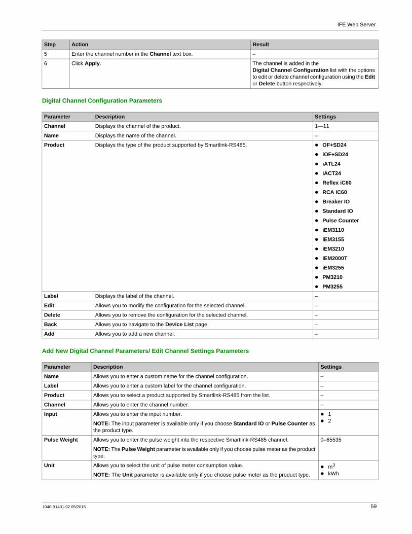
IFE Web Server
Digital Channel Configuration Parameters
Add New Digital Channel Parameters/ Edit Channel Settings Parameters
5 Enter the channel number in the Channel text box. –
6 Click Apply. The channel is added in the Digital Channel Configuration list with the options to edit or delete channel configuration using the Edit or Delete button respectively.
Step Action Result
Parameter Description Settings
Channel Displays the channel of the product. 1—11
Name Displays the name of the channel. –
Product Displays the type of the product supported by Smartlink-RS485. OF+SD24
iOF+SD24
iATL24
iACT24
Reflex iC60
RCA iC60
Breaker IO
Standard IO
Pulse Counter
iEM3110
iEM3155
iEM3210
iEM2000T
iEM3255
PM3210
PM3255
Label Displays the label of the channel. –
Edit Allows you to modify the configuration for the selected channel. –
Delete Allows you to remove the configuration for the selected channel. –
Back Allows you to navigate to the Device List page. –
Add Allows you to add a new channel. –
Parameter Description Settings
Name Allows you to enter a custom name for the channel configuration. –
Label Allows you to enter a custom label for the channel configuration. –
Product Allows you to select a product supported by Smartlink-RS485 from the list. –
Channel Allows you to enter the channel number. –
Input Allows you to enter the input number.
NOTE: The input parameter is available only if you choose Standard IO or Pulse Counter as the product type.
12
Pulse Weight Allows you to enter the pulse weight into the respective Smartlink-RS485 channel.
NOTE: The Pulse Weight parameter is available only if you choose pulse meter as the product type.
0–65535
Unit Allows you to select the unit of pulse meter consumption value.
NOTE: The Unit parameter is available only if you choose pulse meter as the product type.m3
kWh
1040IB1401-02 05/2015 59
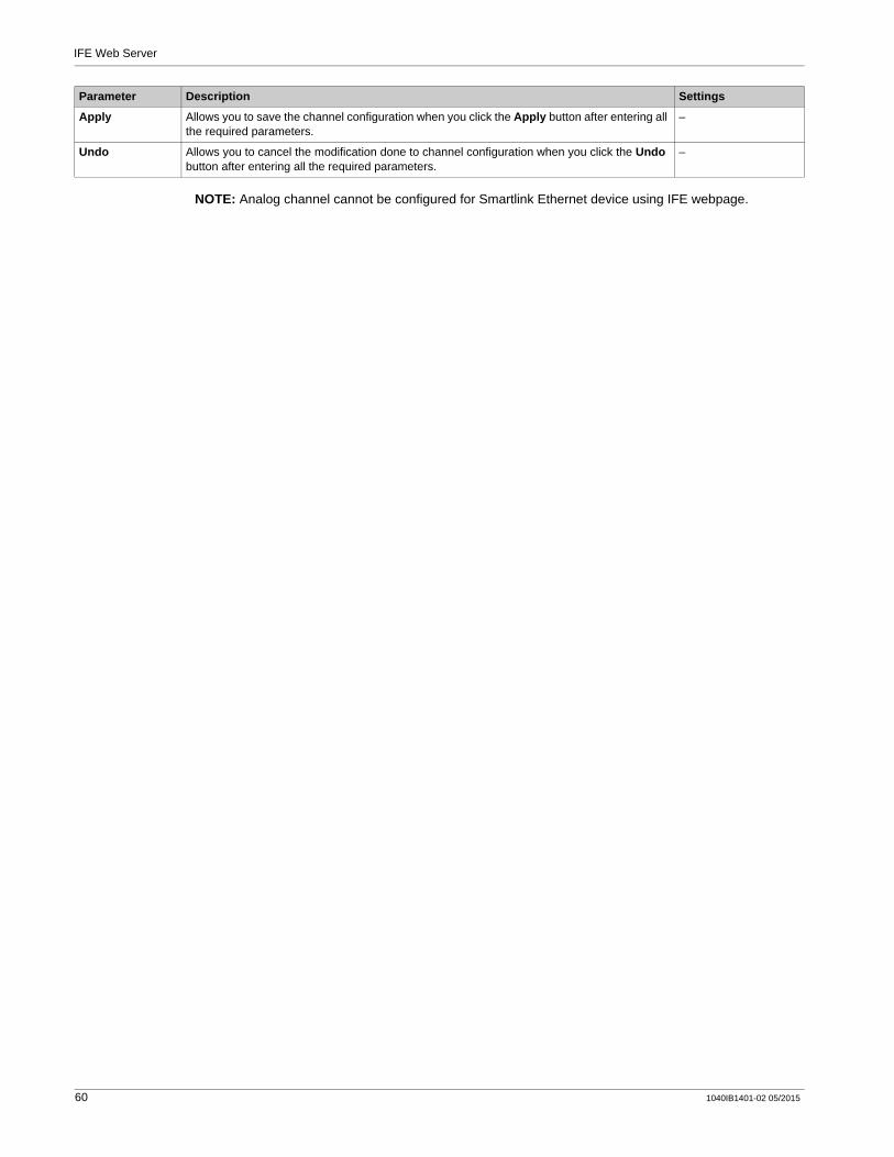
IFE Web Server
NOTE: Analog channel cannot be configured for Smartlink Ethernet device using IFE webpage.
Apply Allows you to save the channel configuration when you click the Apply button after entering all the required parameters.
–
Undo Allows you to cancel the modification done to channel configuration when you click the Undo button after entering all the required parameters.
–
Parameter Description Settings
60 1040IB1401-02 05/2015
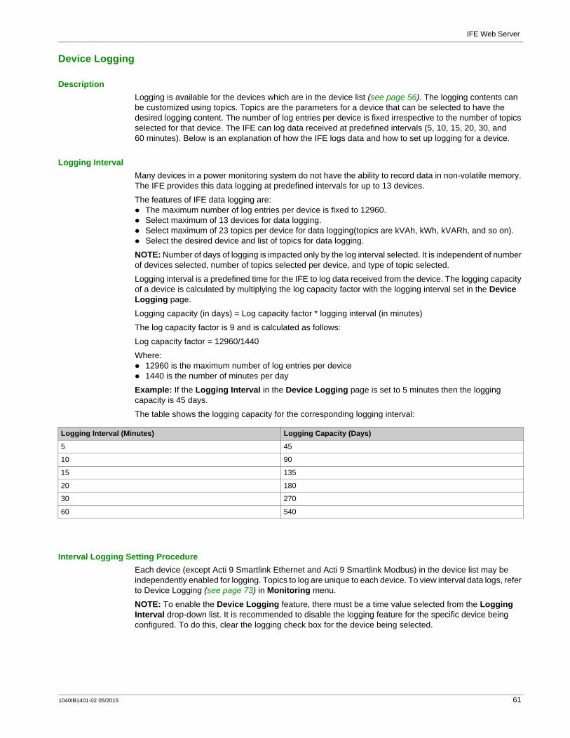
IFE Web Server
Device Logging
DescriptionLogging is available for the devices which are in the device list (see page 56). The logging contents can be customized using topics. Topics are the parameters for a device that can be selected to have the desired logging content. The number of log entries per device is fixed irrespective to the number of topics selected for that device. The IFE can log data received at predefined intervals (5, 10, 15, 20, 30, and 60 minutes). Below is an explanation of how the IFE logs data and how to set up logging for a device.
Logging IntervalMany devices in a power monitoring system do not have the ability to record data in non-volatile memory. The IFE provides this data logging at predefined intervals for up to 13 devices.
The features of IFE data logging are:The maximum number of log entries per device is fixed to 12960.Select maximum of 13 devices for data logging.Select maximum of 23 topics per device for data logging(topics are kVAh, kWh, kVARh, and so on).Select the desired device and list of topics for data logging.
NOTE: Number of days of logging is impacted only by the log interval selected. It is independent of number of devices selected, number of topics selected per device, and type of topic selected.
Logging interval is a predefined time for the IFE to log data received from the device. The logging capacity of a device is calculated by multiplying the log capacity factor with the logging interval set in the Device Logging page.
Logging capacity (in days) = Log capacity factor * logging interval (in minutes)
The log capacity factor is 9 and is calculated as follows:
Log capacity factor = 12960/1440
Where:12960 is the maximum number of log entries per device1440 is the number of minutes per day
Example: If the Logging Interval in the Device Logging page is set to 5 minutes then the logging capacity is 45 days.
The table shows the logging capacity for the corresponding logging interval:
Interval Logging Setting ProcedureEach device (except Acti 9 Smartlink Ethernet and Acti 9 Smartlink Modbus) in the device list may be independently enabled for logging. Topics to log are unique to each device. To view interval data logs, refer to Device Logging (see page 73) in Monitoring menu.
NOTE: To enable the Device Logging feature, there must be a time value selected from the Logging Interval drop-down list. It is recommended to disable the logging feature for the specific device being configured. To do this, clear the logging check box for the device being selected.
Logging Interval (Minutes) Logging Capacity (Days)
5 45
10 90
15 135
20 180
30 270
60 540
1040IB1401-02 05/2015 61

IFE Web Server
LoggingTo disable logging, select a logging interval of zero, ensure that the logging selections are cleared, then click Apply.
Purge DataTo delete a data log, check Purge Data for the topics to be deleted.
CustomizeTo customize logging content, enable device logging. Click Topics under Customize for the device to be configured.
62 1040IB1401-02 05/2015
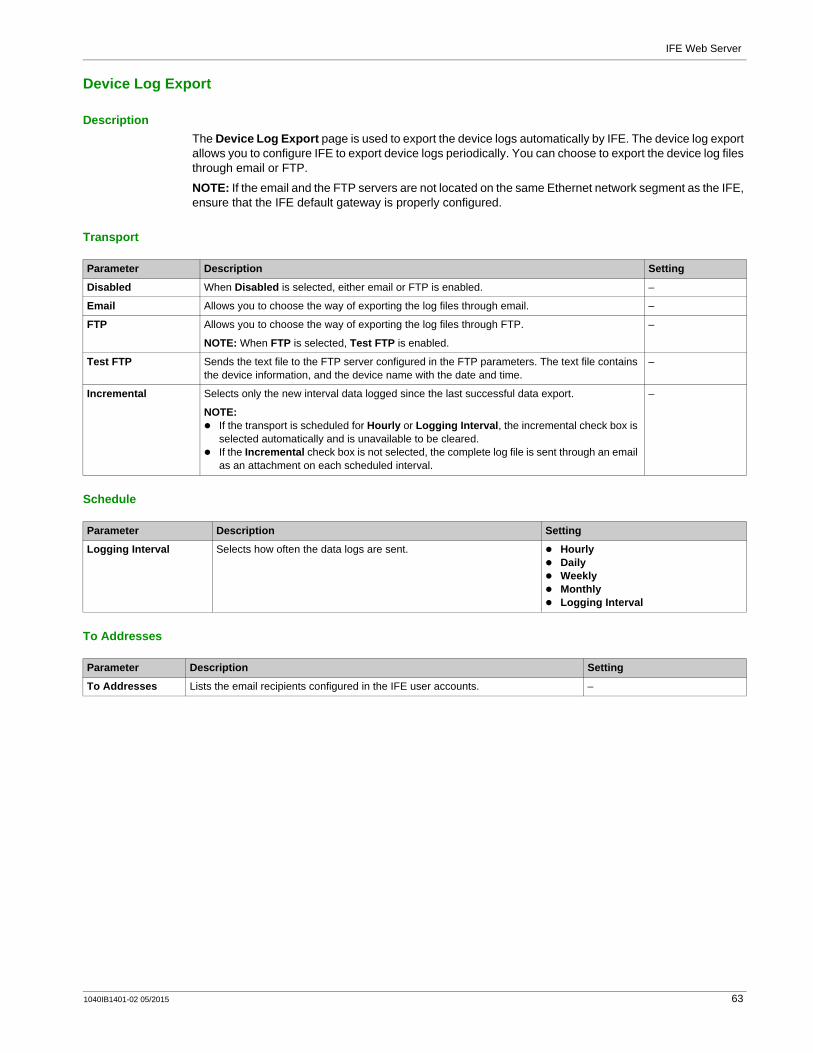
IFE Web Server
Device Log Export
DescriptionThe Device Log Export page is used to export the device logs automatically by IFE. The device log export allows you to configure IFE to export device logs periodically. You can choose to export the device log files through email or FTP.
NOTE: If the email and the FTP servers are not located on the same Ethernet network segment as the IFE, ensure that the IFE default gateway is properly configured.
Transport
Schedule
To Addresses
Parameter Description Setting
Disabled When Disabled is selected, either email or FTP is enabled. –
Email Allows you to choose the way of exporting the log files through email. –
FTP Allows you to choose the way of exporting the log files through FTP.
NOTE: When FTP is selected, Test FTP is enabled.
–
Test FTP Sends the text file to the FTP server configured in the FTP parameters. The text file contains the device information, and the device name with the date and time.
–
Incremental Selects only the new interval data logged since the last successful data export.
NOTE: If the transport is scheduled for Hourly or Logging Interval, the incremental check box is selected automatically and is unavailable to be cleared.If the Incremental check box is not selected, the complete log file is sent through an email as an attachment on each scheduled interval.
–
Parameter Description Setting
Logging Interval Selects how often the data logs are sent. HourlyDailyWeeklyMonthlyLogging Interval
Parameter Description Setting
To Addresses Lists the email recipients configured in the IFE user accounts. –
1040IB1401-02 05/2015 63

IFE Web Server
SNMP Parameters
Manage IP ParametersThe IFE supports SNMP, allowing a network administrator to access remotely an IFE with an SNMP manager and to view the networking status and diagnostics of the IFE in the MIB-II format.
Enabled Traps
Parameter Description Setting
Manager One Allows you to configure the IP address of SNMP manager one. –
Manager Two Allows you to configure the IP address of SNMP manager two. –
System Contact Allows you to configure the SNMP system contact name. –
System Location Allows you to configure the SNMP system location. –
Read-only Community Name Allows you to configure the SNMP read-only community name. Public (Factory setting)
Read-write Community Name Allows you to configure the SNMP read-write community name. Private (Factory setting)
Trap Allows you to trap the community name. Public (Factory setting)
Parameter Description Setting
Coldstart Trap Generates a trap when the IFE is powered ON. –
Warmstart Trap Not supported –
Linkdown Trap Generates a trap when an Ethernet port communication link is disconnected.
–
Linkup Trap Generates a trap when an Ethernet port communication link is reconnected.
–
Authentication Failure Trap Generates a trap when an SNMP manager is accessing the IFE with incorrect authentication.
–
64 1040IB1401-02 05/2015
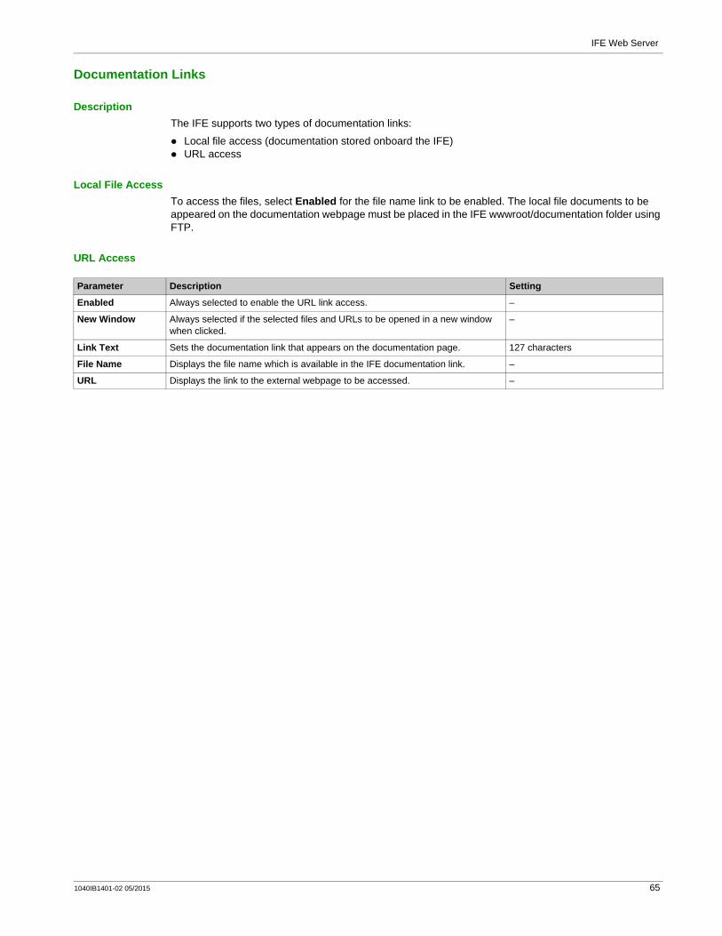
IFE Web Server
Documentation Links
DescriptionThe IFE supports two types of documentation links:
Local file access (documentation stored onboard the IFE)URL access
Local File AccessTo access the files, select Enabled for the file name link to be enabled. The local file documents to be appeared on the documentation webpage must be placed in the IFE wwwroot/documentation folder using FTP.
URL Access
Parameter Description Setting
Enabled Always selected to enable the URL link access. –
New Window Always selected if the selected files and URLs to be opened in a new window when clicked.
–
Link Text Sets the documentation link that appears on the documentation page. 127 characters
File Name Displays the file name which is available in the IFE documentation link. –
URL Displays the link to the external webpage to be accessed. –
1040IB1401-02 05/2015 65

IFE Web Server
Preferences
General Settings
Parameter Description Setting
Equipment Name Displays the equipment name. This name is used in the web interface banner.
NOTE: The device name can be updated in the Device Name of the Device Location/Name in the Configuration & Settings menu.
–
Real Time Sample Rate Controls how often data is read from the device in the standard monitoring table views.
5–60 SecondsFactory setting: 5 seconds
Communication Check Rate Controls how often a communications check is performed while the browser is displaying real-time readings in the standard monitoring table views. This function attempts to bring any out-of-service devices back into service automatically.
5–30 minutesFactory setting: 5 minutes
66 1040IB1401-02 05/2015

IFE Web Server
Advanced Services Control
Industrial Protocol
Services Configuration
Parameter Description Setting
Enable Modbus/TCP Allows you to enable/disable the Modbus/TCP service. Enabled (Factory setting)Disabled
Parameter Description Setting
Enable FTP server Allows you to enable/disable the FTP service. Enabled (Factory setting)Disabled
Enable device announcement Allows you to enable/disable the DPWS service. Enabled (Factory setting)Disabled
Enable SNMP Allows you to enable/disable the SNMP service. Enabled (Factory setting)Disabled
1040IB1401-02 05/2015 67
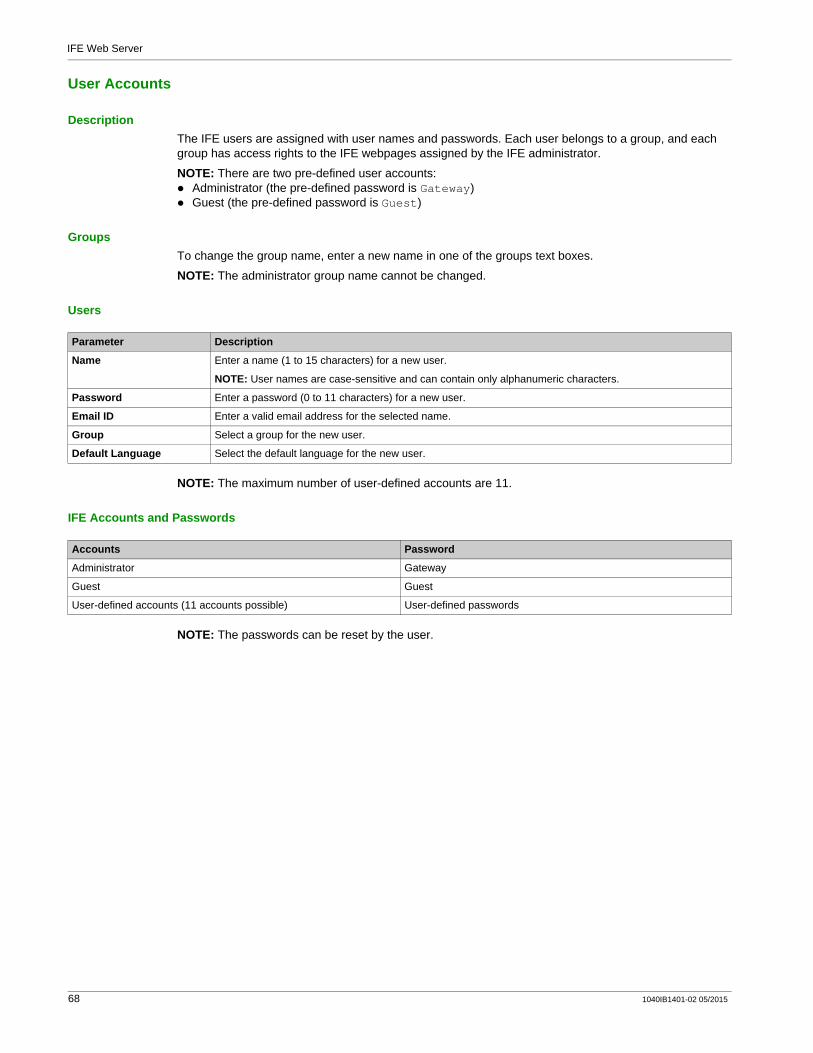
IFE Web Server
User Accounts
DescriptionThe IFE users are assigned with user names and passwords. Each user belongs to a group, and each group has access rights to the IFE webpages assigned by the IFE administrator.
NOTE: There are two pre-defined user accounts:Administrator (the pre-defined password is Gateway)Guest (the pre-defined password is Guest)
GroupsTo change the group name, enter a new name in one of the groups text boxes.
NOTE: The administrator group name cannot be changed.
Users
NOTE: The maximum number of user-defined accounts are 11.
IFE Accounts and Passwords
NOTE: The passwords can be reset by the user.
Parameter Description
Name Enter a name (1 to 15 characters) for a new user.
NOTE: User names are case-sensitive and can contain only alphanumeric characters.
Password Enter a password (0 to 11 characters) for a new user.
Email ID Enter a valid email address for the selected name.
Group Select a group for the new user.
Default Language Select the default language for the new user.
Accounts Password
Administrator Gateway
Guest Guest
User-defined accounts (11 accounts possible) User-defined passwords
68 1040IB1401-02 05/2015
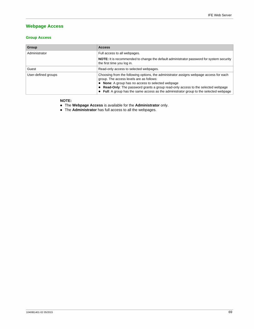
IFE Web Server
Webpage Access
Group Access
NOTE: The Webpage Access is available for the Administrator only.The Administrator has full access to all the webpages.
Group Access
Administrator Full access to all webpages.
NOTE: It is recommended to change the default administrator password for system security the first time you log in.
Guest Read-only access to selected webpages.
User-defined groups Choosing from the following options, the administrator assigns webpage access for each group. The access levels are as follows:
None: A group has no access to selected webpageRead-Only: The password grants a group read-only access to the selected webpageFull: A group has the same access as the administrator group to the selected webpage
1040IB1401-02 05/2015 69

IFE Web Server
IFE Web Server - Monitoring Pages
Section 2.3IFE Web Server - Monitoring Pages
What Is in This Section?This section contains the following topics:
Topic Page
Real Time Data 71
Device Logging 73
70 1040IB1401-02 05/2015

IFE Web Server
Real Time Data
DescriptionThe Real Time Data page provides:
the basic readings of the selected devices in real time on Single Device Pages.the device summaries on Summary Device Pages.the real-time trending for the selected device for the selected topics on Trending.
NOTE: Refresh the webpage by action on the function key F5 when out of service is displayed.
Single Device PagesThis page displays the basic readings like breaker status, cradle status, load current, power, power factor, voltage, and so on, of the selected devices on real-time basis.
The table shows the steps to monitor the real-time data of a device:
Summary Device PagesThe summary device table views provide summary of one or more selected devices.
Trending
Step Action Result
1 From the IFE menu bar, click Monitoring. Opens the Monitoring menu.
2 From the Monitoring menu, in the Real Time Data submenu, select a device from Single Device Pages.
Displays the real-time data of the selected device.
Step Action Result
1 From the Monitoring menu, in the Real Time Data submenu, click Summary Device Pages.
Expands tree for summary page selection choices.
2 Select the Summary Page to be viewed. Opens the device selection list.
3 Select the devices from the Available Devices, then click Apply.
NOTE: Click select all to select all the available devices. Click clear all to clear all the selected devices.
Summary of the selected device appears.
NOTE: Click New selection to navigate back to the device selection list.
Step Action Result
1 From the IFE menu bar, click Monitoring. Opens the Monitoring menu.
2 From the Monitoring menu, in the Real Time Data submenu, select Trending.
Expands the data tree for real-time data option selection and the time trending option selection.
3 Select Real Time Trending. Opens the real-time trending setup page.
4 Select up to 4 devices from the Available Devices list. Selects devices for trending.
5 Select the topics from the Available Topics list.
NOTE: Only topics common to all selected devices are available for trending. The maximum number of topics to trend is dependent on the number of devices selected.The multiplication (product) of the selected devices and the selected topics must be 8 or less.
Selects topics for trending.
6 Click Apply to open the Real Time Trending display page. Opens the real-time trending display page.
7 Set the trending parameters. Allows trending parameters to be set.
1040IB1401-02 05/2015 71

IFE Web Server
Trending Parameters
Step Action Result
1 Select Absolute or Relative trending.
NOTE: Absolute redraws the x-axis in the graph after each sample, filling it with all the data collected since the start of the trend. The Relative updates the graph with the latest data after each sample while the x-axis stays constant to show the overall trend time selected.
Selects graph mode.
2 Choose a trend time from 1–15 minutes. This is the duration of the trend.
NOTE: Data samples are taken as fast as possible but may take longer depending on the communications load on the Modbus-SL port.
Selects the amount of time of the trend.
3 Select Start Sampling to start the trending of the selected device topics.
NOTE: Trending may be stopped before reaching the trend time by clicking Stop Sampling. If Start Sampling is pressed after stopping the sampling, a new trend is started.
Starts trending.
4 Press Data Points to view a log of all the sampled topics recorded during the trend time.
Displays a log of all topic values sampled during the trend.
5 Press New Selection to reselect the devices and topics to trend.
Navigates back to the real-time trending setup page.
72 1040IB1401-02 05/2015

IFE Web Server
Device Logging
IntroductionDevice logging page provides the graphic and table representations of the selected device log data. For more details on configuring device logging, refer to Device Logging (see page 61).
Single Device Pages
The data logged from each device is displayed in a webpage in a time-trend chart format. The time-trend chart is preconfigured to display data from the Last Full Day, Last Full Week, Last Full Month, or All.Energy parameters are logged as accumulating values but are displayed as incremental values on an interval basis. All other parameters are logged and displayed as the actual value recorded.
Retrieving a Data LogInterval data logs can be retrieved using the methods given in the following table:
To view the list of all the available log files, follow steps 2 to 4 in the section Getting an Interval Data Log using FTP (see page 74). Files are in the format: Device Name.csv where the device name is the name given to the slave device. For example, a device named building 1 utility entrance is Building 1 Utility Entrance.csv.
When the log files are exported, the date and time are appended to the file name in the following format: _YYYYMMDDHHMMSS. For example, Building 1 Utility Entrance_20100218115216.csv. This indicates that the file was exported on 2010 February 18 at 11:52:16 AM.
Step Action Result
1 From the IFE menu bar, click Monitoring. Opens the Monitoring menu.
2 From the Monitoring menu, click Device Logging. Expands tree to show available device logging choices.
3 From the Device Logging, click Single Device Pages. Expands tree to show available devices that have logged data available for viewing.
4 Select a device from the Device List. Displays the device log for the selected device.
5 To view a data range, select a period range from the period range drop-down list:
Last Full DayLast Full WeekLast Full MonthAll
Plots the selected period range.
6 Hold the left mouse button and drag a selection box around a graph area to zoom in on it.
Zooms in on the selected graph area.
7 To return to the original full view, enter Z on your keyboard, or double-click the graph.
The view zooms out.
8 Click Data Points to view the selected interval data log table. Opens the selected Interval Data Log table.
9 To view different topics, click New Topic(s). Enable the check boxes of the topics to be displayed, and click Apply.
Enables the display of the selected topics.
Retrieval Method File Format Retrieved
IFE FTP server Comma-separated variable (CSV)
Export to an external FTP server CSV
Data point button HTML
Microsoft web query CSV
Email CSV
1040IB1401-02 05/2015 73

IFE Web Server
Log FormatData is logged in the CSV file with the following format:
If a spreadsheet application is used to view the CSV file, data should look similar to the interval data log opened in a spreadsheet application.
Error Codes for Data LogsThe below error codes may be seen when troubleshooting data logs:
Contact technical support if you need assistance in resolving these or other error conditions.
Retrieving Data Log Using IFE FTP ServerYou can use IFE FTP server to retrieve a data log file by connecting to the IFE via FTP and transferring the .csv file, as shown in the steps below.
NOTE: If you want the IFE to send the data log file via FTP automatically, the device log export must be configured for FTP.
Row Data in CSV Format Description
1 IFE name,IFE sn, IFE address, device name, device local ID, device type name, logging interval.
This row contains the column headings for the information in row 2.
2 IFE 555, 23227,157.198.184.116, building1 utility entrance, 3, CM4000,15
This row contains the information about the IFE and the logged device.
3 This row is blank. –
4 ,,,topic id 1,topic id 2,topic id 3 This row contains the column headings for the topic IDs in row 5. A topic ID is a numerical reference to the quantity being logged. Topic IDs are used to identify the quantity, regardless of the device or language. The first three commas are used for layout purposes in a spreadsheet application.
5 ,,,1617,1621,1625 This row contains the topic IDs of the values logged.
6 This row is blank. –
7 Error, UTC offset (Minutes), local time stamp, apparent energy (kVAh), real energy (kWh), reactive energy (kVARh)
This row contains the column headings for the data logged in rows 8 and higher.
8 and higher These rows contain the logged data.0,-300,2008-10-09 14:15:00,1400738.219,1201962.707,647069.906,150,-300,2008-10-09 14:20:00,1400758.260,1201980.725,647078.602,150,-300,2008-10-09 14:25:00,1400778.198,1201998.661,647087.233,15
Error Code Definition Result
19 Communication error occurred (for example: CRC, protocol, or exception).
Logging is left enabled unless the last interval was missed.
25 Timeout occurred when a request was sent without receiving a corresponding response within the allowed time.
Logging is left enabled unless the last interval was missed.
38 Invalid data. -
100 Interval time expired before data could be recorded. Missed interval.
Step Action Result
1 Create a folder on your computer, such as C\:file_logs. Creates a folder to store the IFE data log.
2 Launch Windows Explorer, enter ftp:// and the IP address of the IFE in the address text box (for example, ftp://169.254.0.10), press Enter.
Opens the Log On As dialog box.
3 Enter the user name as Administrator and password as Gateway in the text boxes, click Log On.
Opens an FTP session with the IFE and displays the files stored in the IFE.
4 Navigate to the directory/logging/data on the IFE. Opens the data logging directory on the IFE.
5 Copy the log file and paste it into the folder created in step 1. Copies the data log to the folder.
74 1040IB1401-02 05/2015
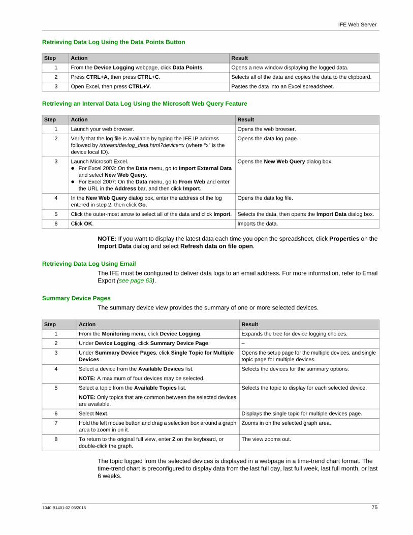
IFE Web Server
Retrieving Data Log Using the Data Points Button
Retrieving an Interval Data Log Using the Microsoft Web Query Feature
NOTE: If you want to display the latest data each time you open the spreadsheet, click Properties on the Import Data dialog and select Refresh data on file open.
Retrieving Data Log Using EmailThe IFE must be configured to deliver data logs to an email address. For more information, refer to Email Export (see page 63).
Summary Device PagesThe summary device view provides the summary of one or more selected devices.
The topic logged from the selected devices is displayed in a webpage in a time-trend chart format. The time-trend chart is preconfigured to display data from the last full day, last full week, last full month, or last 6 weeks.
Step Action Result
1 From the Device Logging webpage, click Data Points. Opens a new window displaying the logged data.
2 Press CTRL+A, then press CTRL+C. Selects all of the data and copies the data to the clipboard.
3 Open Excel, then press CTRL+V. Pastes the data into an Excel spreadsheet.
Step Action Result
1 Launch your web browser. Opens the web browser.
2 Verify that the log file is available by typing the IFE IP address followed by /stream/devlog_data.html?device=x (where “x” is the device local ID).
Opens the data log page.
3 Launch Microsoft Excel.For Excel 2003: On the Data menu, go to Import External Data and select New Web Query.For Excel 2007: On the Data menu, go to From Web and enter the URL in the Address bar, and then click Import.
Opens the New Web Query dialog box.
4 In the New Web Query dialog box, enter the address of the log entered in step 2, then click Go.
Opens the data log file.
5 Click the outer-most arrow to select all of the data and click Import. Selects the data, then opens the Import Data dialog box.
6 Click OK. Imports the data.
Step Action Result
1 From the Monitoring menu, click Device Logging. Expands the tree for device logging choices.
2 Under Device Logging, click Summary Device Page. –
3 Under Summary Device Pages, click Single Topic for Multiple Devices.
Opens the setup page for the multiple devices, and single topic page for multiple devices.
4 Select a device from the Available Devices list.
NOTE: A maximum of four devices may be selected.
Selects the devices for the summary options.
5 Select a topic from the Available Topics list.
NOTE: Only topics that are common between the selected devices are available.
Selects the topic to display for each selected device.
6 Select Next. Displays the single topic for multiple devices page.
7 Hold the left mouse button and drag a selection box around a graph area to zoom in on it.
Zooms in on the selected graph area.
8 To return to the original full view, enter Z on the keyboard, or double-click the graph.
The view zooms out.
1040IB1401-02 05/2015 75

IFE Web Server
Energy parameters are displayed as incremental values on an interval basis. All other parameters are logged and displayed as the actual value recorded.
76 1040IB1401-02 05/2015
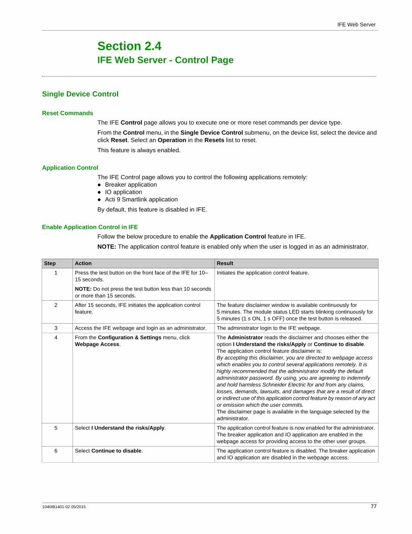
IFE Web Server
IFE Web Server - Control Page
Section 2.4IFE Web Server - Control Page
Single Device Control
Reset CommandsThe IFE Control page allows you to execute one or more reset commands per device type.
From the Control menu, in the Single Device Control submenu, on the device list, select the device and click Reset. Select an Operation in the Resets list to reset.
This feature is always enabled.
Application Control The IFE Control page allows you to control the following applications remotely:
Breaker applicationIO applicationActi 9 Smartlink application
By default, this feature is disabled in IFE.
Enable Application Control in IFEFollow the below procedure to enable the Application Control feature in IFE.
NOTE: The application control feature is enabled only when the user is logged in as an administrator.
Step Action Result
1 Press the test button on the front face of the IFE for 10–15 seconds.
NOTE: Do not press the test button less than 10 seconds or more than 15 seconds.
Initiates the application control feature.
2 After 15 seconds, IFE initiates the application control feature.
The feature disclaimer window is available continuously for 5 minutes. The module status LED starts blinking continuously for 5 minutes (1 s ON, 1 s OFF) once the test button is released.
3 Access the IFE webpage and login as an administrator. The administrator login to the IFE webpage.
4 From the Configuration & Settings menu, click Webpage Access.
The Administrator reads the disclaimer and chooses either the option I Understand the risks/Apply or Continue to disable.The application control feature disclaimer is:By accepting this disclaimer, you are directed to webpage access which enables you to control several applications remotely. It is highly recommended that the administrator modify the default administrator password. By using, you are agreeing to indemnify and hold harmless Schneider Electric for and from any claims, losses, demands, lawsuits, and damages that are a result of direct or indirect use of this application control feature by reason of any act or emission which the user commits.The disclaimer page is available in the language selected by the administrator.
5 Select I Understand the risks/Apply. The application control feature is now enabled for the administrator. The breaker application and IO application are enabled in the webpage access for providing access to the other user groups.
6 Select Continue to disable. The application control feature is disabled. The breaker application and IO application are disabled in the webpage access.
1040IB1401-02 05/2015 77
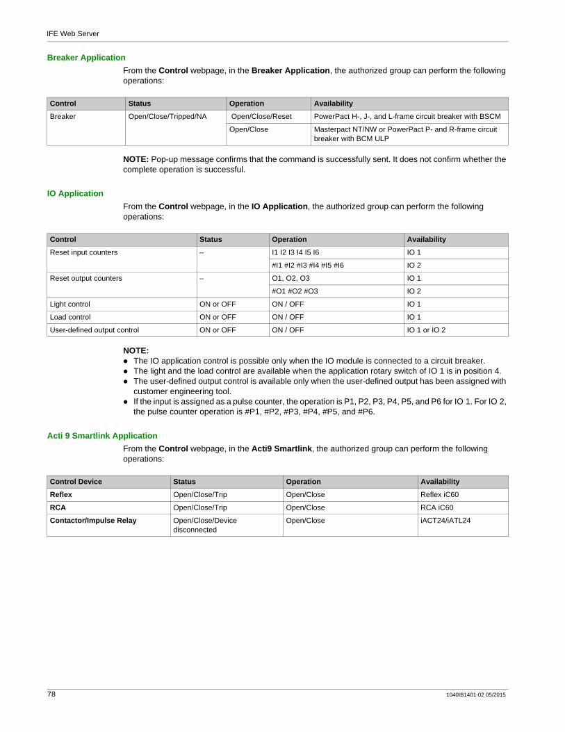
IFE Web Server
Breaker ApplicationFrom the Control webpage, in the Breaker Application, the authorized group can perform the following operations:
NOTE: Pop-up message confirms that the command is successfully sent. It does not confirm whether the complete operation is successful.
IO ApplicationFrom the Control webpage, in the IO Application, the authorized group can perform the following operations:
NOTE: The IO application control is possible only when the IO module is connected to a circuit breaker.The light and the load control are available when the application rotary switch of IO 1 is in position 4.The user-defined output control is available only when the user-defined output has been assigned with customer engineering tool.If the input is assigned as a pulse counter, the operation is P1, P2, P3, P4, P5, and P6 for IO 1. For IO 2, the pulse counter operation is #P1, #P2, #P3, #P4, #P5, and #P6.
Acti 9 Smartlink ApplicationFrom the Control webpage, in the Acti9 Smartlink, the authorized group can perform the following operations:
Control Status Operation Availability
Breaker Open/Close/Tripped/NA Open/Close/Reset PowerPact H-, J-, and L-frame circuit breaker with BSCM
Open/Close Masterpact NT/NW or PowerPact P- and R-frame circuit breaker with BCM ULP
Control Status Operation Availability
Reset input counters – I1 I2 I3 I4 I5 I6 IO 1
#I1 #I2 #I3 #I4 #I5 #I6 IO 2
Reset output counters – O1, O2, O3 IO 1
#O1 #O2 #O3 IO 2
Light control ON or OFF ON / OFF IO 1
Load control ON or OFF ON / OFF IO 1
User-defined output control ON or OFF ON / OFF IO 1 or IO 2
Control Device Status Operation Availability
Reflex Open/Close/Trip Open/Close Reflex iC60
RCA Open/Close/Trip Open/Close RCA iC60
Contactor/Impulse Relay Open/Close/Device disconnected
Open/Close iACT24/iATL24
78 1040IB1401-02 05/2015
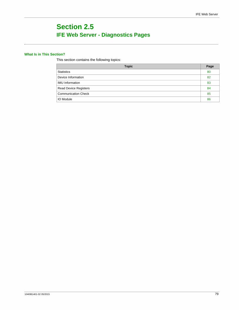
IFE Web Server
IFE Web Server - Diagnostics Pages
Section 2.5IFE Web Server - Diagnostics Pages
What Is in This Section?This section contains the following topics:
Topic Page
Statistics 80
Device Information 82
IMU Information 83
Read Device Registers 84
Communication Check 85
IO Module 86
1040IB1401-02 05/2015 79
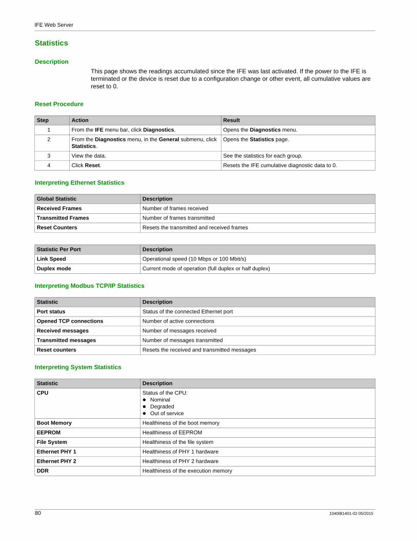
IFE Web Server
Statistics
DescriptionThis page shows the readings accumulated since the IFE was last activated. If the power to the IFE is terminated or the device is reset due to a configuration change or other event, all cumulative values are reset to 0.
Reset Procedure
Interpreting Ethernet Statistics
Interpreting Modbus TCP/IP Statistics
Interpreting System Statistics
Step Action Result
1 From the IFE menu bar, click Diagnostics. Opens the Diagnostics menu.
2 From the Diagnostics menu, in the General submenu, click Statistics.
Opens the Statistics page.
3 View the data. See the statistics for each group.
4 Click Reset. Resets the IFE cumulative diagnostic data to 0.
Global Statistic Description
Received Frames Number of frames received
Transmitted Frames Number of frames transmitted
Reset Counters Resets the transmitted and received frames
Statistic Per Port Description
Link Speed Operational speed (10 Mbps or 100 Mbit/s)
Duplex mode Current mode of operation (full duplex or half duplex)
Statistic Description
Port status Status of the connected Ethernet port
Opened TCP connections Number of active connections
Received messages Number of messages received
Transmitted messages Number of messages transmitted
Reset counters Resets the received and transmitted messages
Statistic Description
CPU Status of the CPU:NominalDegradedOut of service
Boot Memory Healthiness of the boot memory
EEPROM Healthiness of EEPROM
File System Healthiness of the file system
Ethernet PHY 1 Healthiness of PHY 1 hardware
Ethernet PHY 2 Healthiness of PHY 2 hardware
DDR Healthiness of the execution memory
80 1040IB1401-02 05/2015

IFE Web Server
Interpreting Date and Time Statistics
Interpreting Modbus Serial Statistics
Interpreting ULP Statistics
Interpreting File System Statistics
Interpreting TCP Port Connections Statistics
Statistic Description
Date Current date
Time Current time
Uptime Run time during the system power-up
Statistic Description
Transmitted Message A counter that increments each time a frame is sent.
Received Message A counter that increments each time a frame is received.
Error Message An error marked from the slave or the response timeout.
Statistic Description
Frames Transmitted Number of CAN frames transmitted successfully
Frame Received Number of CAN frames received successfully
Max Transmit Error Maximum number of CAN transmitted errors (TEC)
Max Receive Error Maximum number of CAN received errors (REC)
Bus off CAN Bus off count
Max Bus off Maximum number of bus off counts
Statistic Description
Total Size Total amount of the IFE disk size in kilobytes
Used Size Total amount of used disk size on the IFE disk in kilobytes
Free Size Total amount of unused disk space on the IFE disk in kilobytes
Bad Size Amount of corrupted disk space on the IFE disk in kilobytes
Statistics Description
Remote IP Remote IP address
Remote Port Remote port number
Transmitted messages Number of messages transmitted
Received message Number of messages received
Sent Errors Number of error messages sent
Reset Counters Resets the transmitted and received messages
1040IB1401-02 05/2015 81
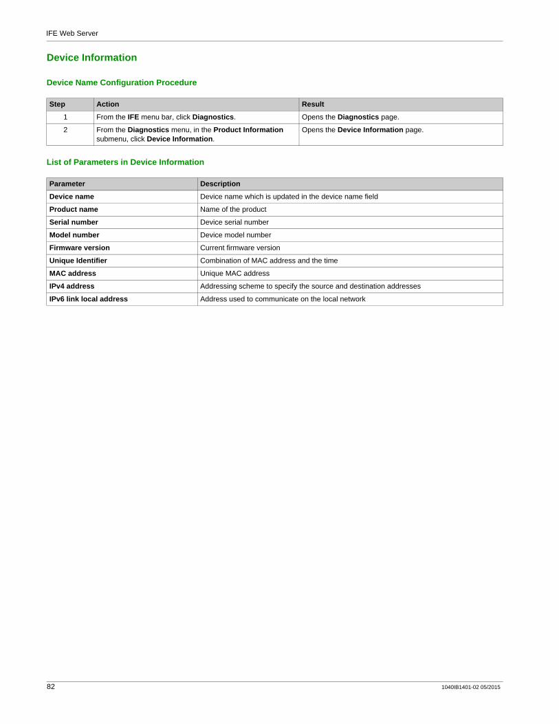
IFE Web Server
Device Information
Device Name Configuration Procedure
List of Parameters in Device Information
Step Action Result
1 From the IFE menu bar, click Diagnostics. Opens the Diagnostics page.
2 From the Diagnostics menu, in the Product Information submenu, click Device Information.
Opens the Device Information page.
Parameter Description
Device name Device name which is updated in the device name field
Product name Name of the product
Serial number Device serial number
Model number Device model number
Firmware version Current firmware version
Unique Identifier Combination of MAC address and the time
MAC address Unique MAC address
IPv4 address Addressing scheme to specify the source and destination addresses
IPv6 link local address Address used to communicate on the local network
82 1040IB1401-02 05/2015

IFE Web Server
IMU Information
DescriptionThis page gives the information about the devices which are connected to the IFE in ULP port. The devices connected are:
Breaker Communication ModuleBreaker Communication Module for ULP systemMicrologic Trip UnitBreaker Status and Communication ModuleFDM121 display for LV circuit breakerIO 1IO 2Maintenance module
1040IB1401-02 05/2015 83
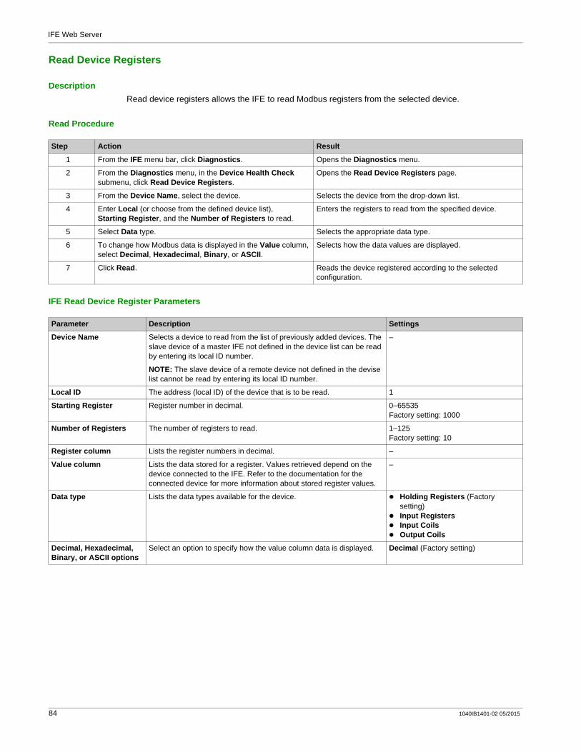
IFE Web Server
Read Device Registers
DescriptionRead device registers allows the IFE to read Modbus registers from the selected device.
Read Procedure
IFE Read Device Register Parameters
Step Action Result
1 From the IFE menu bar, click Diagnostics. Opens the Diagnostics menu.
2 From the Diagnostics menu, in the Device Health Check submenu, click Read Device Registers.
Opens the Read Device Registers page.
3 From the Device Name, select the device. Selects the device from the drop-down list.
4 Enter Local (or choose from the defined device list), Starting Register, and the Number of Registers to read.
Enters the registers to read from the specified device.
5 Select Data type. Selects the appropriate data type.
6 To change how Modbus data is displayed in the Value column, select Decimal, Hexadecimal, Binary, or ASCII.
Selects how the data values are displayed.
7 Click Read. Reads the device registered according to the selected configuration.
Parameter Description Settings
Device Name Selects a device to read from the list of previously added devices. The slave device of a master IFE not defined in the device list can be read by entering its local ID number.
NOTE: The slave device of a remote device not defined in the devise list cannot be read by entering its local ID number.
–
Local ID The address (local ID) of the device that is to be read. 1
Starting Register Register number in decimal. 0–65535Factory setting: 1000
Number of Registers The number of registers to read. 1–125Factory setting: 10
Register column Lists the register numbers in decimal. –
Value column Lists the data stored for a register. Values retrieved depend on the device connected to the IFE. Refer to the documentation for the connected device for more information about stored register values.
–
Data type Lists the data types available for the device. Holding Registers (Factory setting)Input RegistersInput CoilsOutput Coils
Decimal, Hexadecimal, Binary, or ASCII options
Select an option to specify how the value column data is displayed. Decimal (Factory setting)
84 1040IB1401-02 05/2015

IFE Web Server
Communication Check
Automated Communication CheckWhile browsing the real-time data views, the IFE has an automated communication check that runs every 15 minutes by default. To change the timing, refer to Preferences (see page 66). This check verifies the communication health of all the devices configured on the IFE, and attempts to re-establish the communication to any device marked out of service within the current browser session.
Manual Communication CheckIn certain cases, there is no need to wait for the automated communications check interval and need to force the check to run manually.
Step Action Result
1 From the IFE menu bar, click Diagnostics. Opens the Diagnostics menu.
2 From the Diagnostics menu, in the Device Health Check submenu, click Communication Check.
Opens the Communication Check page.
3 Click Check Device Status. Runs a communications check.The communicating device displays:
Passed in the Comms column.In Service in the Status column.
A device that is not communicating display:Failed in the Comms column.Out of Service in the Status column if it has failed multiple times.
1040IB1401-02 05/2015 85
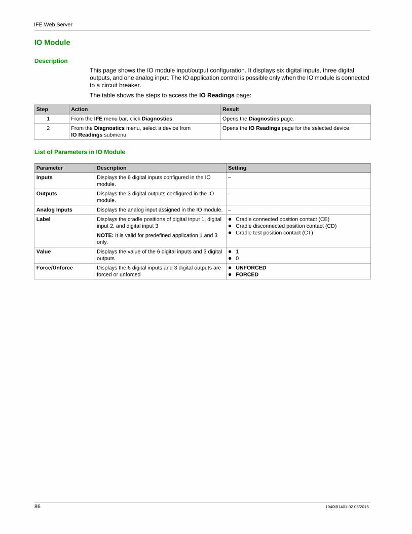
IFE Web Server
IO Module
DescriptionThis page shows the IO module input/output configuration. It displays six digital inputs, three digital outputs, and one analog input. The IO application control is possible only when the IO module is connected to a circuit breaker.
The table shows the steps to access the IO Readings page:
List of Parameters in IO Module
Step Action Result
1 From the IFE menu bar, click Diagnostics. Opens the Diagnostics page.
2 From the Diagnostics menu, select a device from IO Readings submenu.
Opens the IO Readings page for the selected device.
Parameter Description Setting
Inputs Displays the 6 digital inputs configured in the IO module.
–
Outputs Displays the 3 digital outputs configured in the IO module.
–
Analog Inputs Displays the analog input assigned in the IO module. –
Label Displays the cradle positions of digital input 1, digital input 2, and digital input 3
NOTE: It is valid for predefined application 1 and 3 only.
Cradle connected position contact (CE)Cradle disconnected position contact (CD)Cradle test position contact (CT)
Value Displays the value of the 6 digital inputs and 3 digital outputs
10
Force/Unforce Displays the 6 digital inputs and 3 digital outputs are forced or unforced
UNFORCEDFORCED
86 1040IB1401-02 05/2015

IFE Web Server
IFE Web Server - Maintenance Pages
Section 2.6IFE Web Server - Maintenance Pages
What Is in This Section?This section contains the following topics:
Topic Page
Maintenance Log 88
Maintenance Counters 89
Restore the Smartlink’s 90
1040IB1401-02 05/2015 87
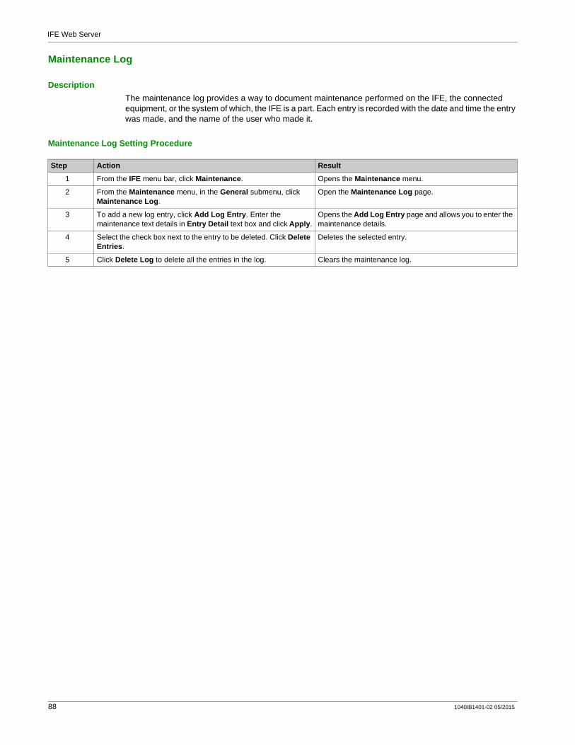
IFE Web Server
Maintenance Log
DescriptionThe maintenance log provides a way to document maintenance performed on the IFE, the connected equipment, or the system of which, the IFE is a part. Each entry is recorded with the date and time the entry was made, and the name of the user who made it.
Maintenance Log Setting Procedure
Step Action Result
1 From the IFE menu bar, click Maintenance. Opens the Maintenance menu.
2 From the Maintenance menu, in the General submenu, click Maintenance Log.
Open the Maintenance Log page.
3 To add a new log entry, click Add Log Entry. Enter the maintenance text details in Entry Detail text box and click Apply.
Opens the Add Log Entry page and allows you to enter the maintenance details.
4 Select the check box next to the entry to be deleted. Click Delete Entries.
Deletes the selected entry.
5 Click Delete Log to delete all the entries in the log. Clears the maintenance log.
88 1040IB1401-02 05/2015
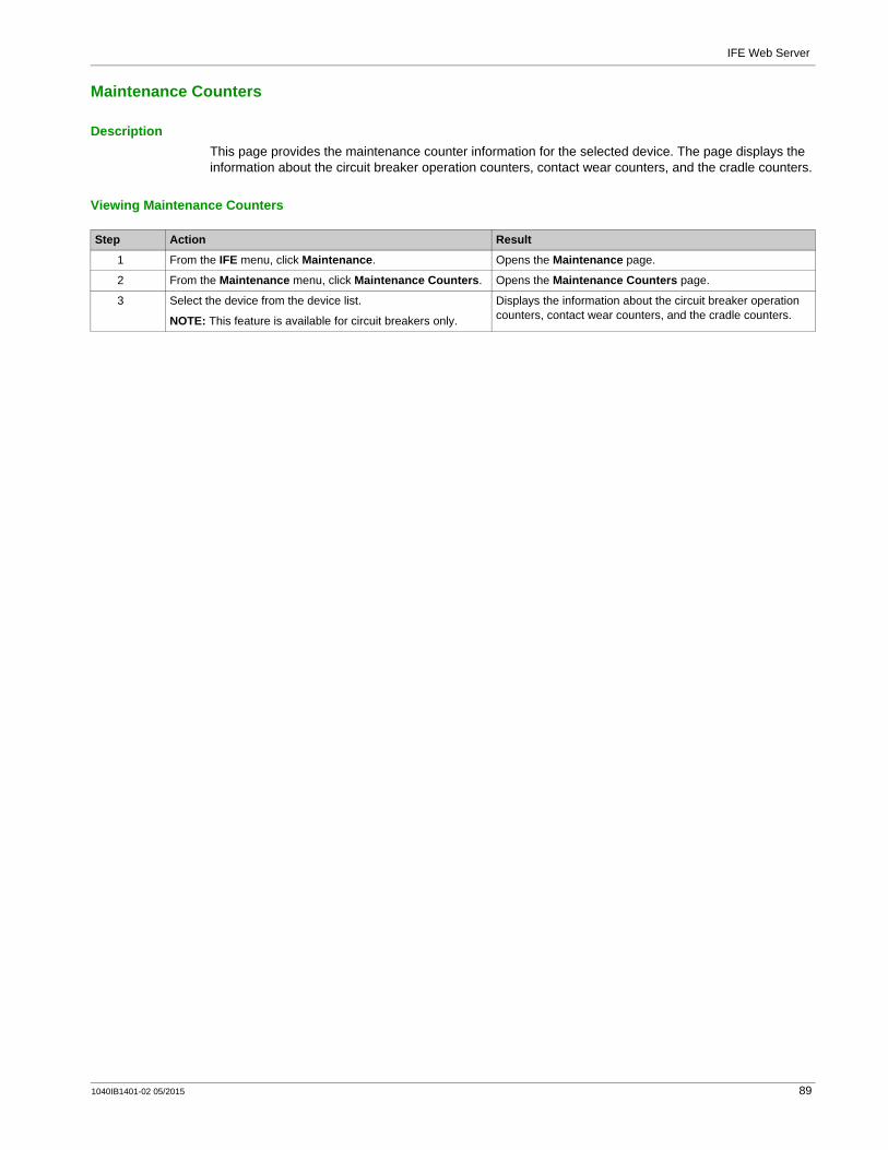
IFE Web Server
Maintenance Counters
DescriptionThis page provides the maintenance counter information for the selected device. The page displays the information about the circuit breaker operation counters, contact wear counters, and the cradle counters.
Viewing Maintenance Counters
Step Action Result
1 From the IFE menu, click Maintenance. Opens the Maintenance page.
2 From the Maintenance menu, click Maintenance Counters. Opens the Maintenance Counters page.
3 Select the device from the device list.
NOTE: This feature is available for circuit breakers only.
Displays the information about the circuit breaker operation counters, contact wear counters, and the cradle counters.
1040IB1401-02 05/2015 89
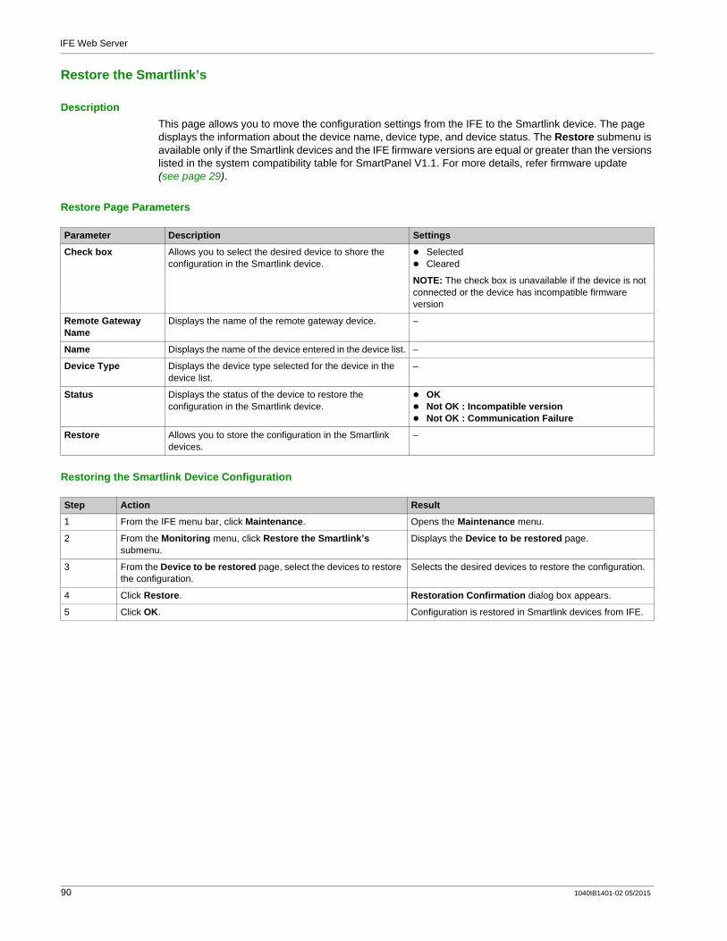
IFE Web Server
Restore the Smartlink’s
DescriptionThis page allows you to move the configuration settings from the IFE to the Smartlink device. The page displays the information about the device name, device type, and device status. The Restore submenu is available only if the Smartlink devices and the IFE firmware versions are equal or greater than the versions listed in the system compatibility table for SmartPanel V1.1. For more details, refer firmware update (see page 29).
Restore Page Parameters
Restoring the Smartlink Device Configuration
Parameter Description Settings
Check box Allows you to select the desired device to shore the configuration in the Smartlink device.
SelectedCleared
NOTE: The check box is unavailable if the device is not connected or the device has incompatible firmware version
Remote Gateway Name
Displays the name of the remote gateway device. –
Name Displays the name of the device entered in the device list. –
Device Type Displays the device type selected for the device in the device list.
–
Status Displays the status of the device to restore the configuration in the Smartlink device.
OKNot OK : Incompatible versionNot OK : Communication Failure
Restore Allows you to store the configuration in the Smartlink devices.
–
Step Action Result
1 From the IFE menu bar, click Maintenance. Opens the Maintenance menu.
2 From the Monitoring menu, click Restore the Smartlink’s submenu.
Displays the Device to be restored page.
3 From the Device to be restored page, select the devices to restore the configuration.
Selects the desired devices to restore the configuration.
4 Click Restore. Restoration Confirmation dialog box appears.
5 Click OK. Configuration is restored in Smartlink devices from IFE.
90 1040IB1401-02 05/2015
IFE Ethernet Interface for LV Circuit Breaker
1040IB1401-02 05/2015
Appendices
1040IB1401-02 05/2015 91

92 1040IB1401-02 05/2015

IFE Ethernet Interface for LV Circuit BreakerAppendix A - List of IFE Supported Devices1040IB1401-02 05/2015
Appendix A - List of IFE Supported Devices
Appendix AAppendix A - List of IFE Supported Devices
List of IFE Supported Device Types
DescriptionThe table below gives the list of devices that can be connected as Modbus slaves on an IFM stacked to the IFE gateway. This list of supported devices was accurate at the time this document was published. Check www.schneider-electric.com for updates.
Device Group Device
Masterpact NT/NW, Compact NS, and PowerPact P- and R-frame circuit breakers with Micrologic trip units
Micrologic A
Micrologic E
Micrologic P
Micrologic H
Compact NSX and PowerPact H-, J-, and L-frame circuit breakers with Micrologic trip units
Compact NSX-A
Compact NSX-E
PowerPact - A
PowerPact - E
Insulation monitoring devices Vigilohm IM20
Vigilohm IM20-H
Power factor controller Varlogic
Power meters PM810
PM820
PM850
PM870
PM9C
PM1200
PM3250
PM3255
PM5320
PM5340
PM5350
PM5560
PM5561
PM5563
iEM3250
iEM3255
iEM3350
iEM3355
Others Acti 9 Smartlink Modbus
Acti 9 Smartlink Ethernet
1040IB1401-02 05/2015 93

Appendix A - List of IFE Supported Devices
94 1040IB1401-02 05/2015


As standards, specifications and designs change from time to time, please ask for confirmation of the information given in this publication.
1040IB1401-02
Schneider Electric Industries SAS35, rue Joseph MonierCS30323F - 92506 Rueil Malmaison Cedex
www.schneider-electric.com 05/2015