Embed Size (px)
Citation preview
Industry Foundation Classes - Release 2.0
IFC Object Model Architecture Guide
15-Mar-99
International Alliance for InteroperabilityEnabling Interoperability in the AEC/FM Industry

Industry Foundation Classes - Release 2.0
IFC Object Model Architecture Guide
Enabling Interoperability in the AEC/FM Industry
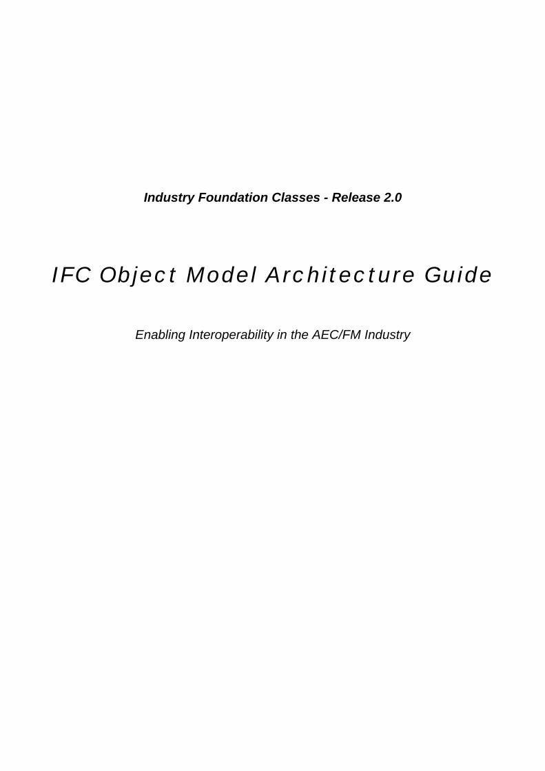
Copyright 1996-99 - International Alliance of Interoperability (IAI)
Mailing address: 2960 Chain Bridge Road - Suite 143Oakton, Virginia 22124
Email address: [email protected]
Web Address: www.Interoperability.com
All rights reserved. No part of the contents of this document may be reproduced ortransmitted in any form or by any means without the written permission of thecopyright holder (IAI).
Document Editor
Editor Thomas Liebich (primary) / Richard See (secondary)Development committee Specification Task Force
Document Control
Project reference IFC Release 2.0Document reference IFC Object Model Architecture GuideDocument version FinalRelease date 15-Mar-99Status ReleasedDistribution PublicDistribution format PDF file
RevisionsRev. Person Date DescriptionAlpha Thomas Liebich 10-Aug-98 Alpha releaseBeta, d1 Thomas Liebich 18-Dec-98 Beta releaseBeta, d2 Richard See 10-Jan-99 Std. front end, page layout, fix figures indexingFinal, d3 Richard See 15-Mar-99 Final adjustments
Table of Contents Page i
Copyright International Alliance for Interoperability - 1996-1999 IFC Release 2.0
Table of Contents
1 INTRODUCTION AND BACKGROUND...............................................................................................11.1 ABOUT THIS DOCUMENT .......................................................................................................................11.2 ASSUMPTIONS AND ABBREVIATIONS .....................................................................................................1
2 BASELINE OF IFC MODEL ARCHITECTURE ....................................................................................22.1 SHORT HISTORY OF INFORMATION MODELING.......................................................................................22.2 IFC MODEL ARCHITECTURE PRINCIPLES ..............................................................................................3
3 IFC MODEL ARCHITECTURE DECOMPOSITION..............................................................................53.1 RESOURCE LAYER ...............................................................................................................................5
3.1.1 Resource schemas for R1.5 .......................................................................................................53.1.2 Resource schemas for R2.0 .......................................................................................................5
3.2 CORE LAYER .......................................................................................................................................63.2.1 Kernel..........................................................................................................................................63.2.2 Core Extensions..........................................................................................................................63.2.3 Core schemas for R1.5 ...............................................................................................................73.2.4 Core schemas for R2.5 ...............................................................................................................7
3.3 INTEROPERABILITY LAYER....................................................................................................................73.3.1 Interoperability schemas for R1.5 ...............................................................................................83.3.2 Interoperability schemas for R2.0 ...............................................................................................83.3.3 Adapter Definitions......................................................................................................................8
3.4 DOMAIN/APPLICATIONS LAYER .............................................................................................................83.4.1 Domain Models for R1.5 .............................................................................................................93.4.2 Domain Models for R2.0 .............................................................................................................9
Page ii Table of Contents
IFC Release 2.0 Copyright International Alliance for Interoperability - 1996-1999
IFC Object Model Architecture Guide Page 1
Copyright International Alliance for Interoperability - 1996-1999 IFC Release 2.0
1 Introduction and Background
1.1 About this document
The document has been developed to serve as the underlying guide for the design of the IFC object model.The intended audience is the Specification Task Force (STF), the Technical Coordinators (TC's) of theconstituent IAI chapters, and the technical co-chairs of the domain projects. The STF is responsible forapplying these guidelines during the development of IFC object model specifications.
1.2 Assumptions and Abbreviations
This document assumes the reader is reasonably familiar with the following:• AEC/FM market and project terminology• Software industry terminology• Concepts and terminology associated with object oriented software• Concepts and terminology associated with information modeling
The following abbreviations are used throughout the IFC Specifications:• AEC/FM Architectural, Engineering, Construction and Facilities Management• AP Application Protocol• Arch Architecture• CM Construction Management• CORBA Common Object Request Broker Architecture• COM Microsoft’s Component Object Model• DCE Distributed Computing Environment• DCOM Microsoft’s Distributed Component Object Model• DSOM IBM’s Distributed System Object Model• FM Facilities Management• FTP File Transfer Protocol• GUID Globally Unique Identifier• HVAC Heating, Ventilating and Air Conditioning• HTTP Hypertext Transport Protocol• IAI International Alliance for Interoperability• IDL Interface Definition Language• IFC Industry Foundation Classes• IM Information Model• ISO International Standards Organization• FM Facilities Management• MIDL Microsoft’s Interface Definition Language• ODL Microsoft’s Object Description Language• OMG Object Management Group• ORB Object Request Broker• OSF Open Software Foundation• RPC Remote Procedure Call• SOM IBM’s System Object Model• STEP Standard for the Exchange of Product Model Data• TCP/IP Transmission Control Protocol/Internet Protocol• TQM Total Quality Management• URL Universal Resource Locator
Page 2 IFC Object Model Architecture Guide
IFC Release 2.0 Copyright International Alliance for Interoperability - 1996-1999
2 Baseline of IFC Model ArchitectureThe scope defined by the IAI for the IFC Object Model is "enabling interoperability between AEC/FMapplications from different software vendors". The AEC/FM industry is, by its nature, fragmented anddistributed. It also encompasses a very large set of object model requirements. Many axes can be describedalong which model requirements occur and can alter, such as:
• disciplines involved in AEC/FM processes• life-cycle stages of AEC/FM projects• level of detail required
In order to satisfy all model requirements the IFC Object Model has to be structured in order to allow both,diversification to cope with the various information axes, and centralization to harmonize and integrate thevarious diversified modules.
Development of an information model being of the size of the IFC Object Model requires team work anddistributed responsibilities. The structure of the information model has to provide for both, encapsulatedmodules for relatively autonomous work, and overall rigid structure to facilitate a centralized integration of thatwork.
In understanding this, it becomes obvious that the IFC Object Model must be decomposed into smaller andmore manageable modules, which are interconnected by a rigid overall structure. This document provides therationale for such structure and presents the architecture for the IFC Object Model.
2.1 Short History of Information Modeling
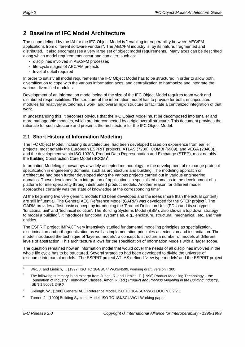
The IFC Object Model, including its architecture, had been developed based on experience from earlierprojects, most notably the European ESPRIT projects, ATLAS (7280), COMBI (6909), and VEGA (20408),and the development within ISO 10303, Product Data Representation and Exchange (STEP), most notablythe Building Construction Core Model (BCCM)1.
Information Modeling is nowadays a widely accepted methodology for the development of exchange protocolspecification in engineering domains, such as architecture and building. The modeling approach orarchitecture had been further developed along the various projects carried out in various engineeringdomains. These developed from integration of applications in specialized domains to the development of aplatform for interoperability through distributed product models. Another reason for different modelapproaches certainly was the state of knowledge at the corresponding time2.
At the beginning two very generic models had been developed and the ideas (more than the actual content)are still influential. The General AEC Reference Model (GARM) was developed for the STEP project3. TheGARM provides a first basic concept by introducing the 'Product Definition Unit' (PDU) and its subtypes'functional unit' and 'technical solution'. The Building Systems Model (BSM), also shows a top down strategyto model a building4. It introduces functional systems as, e.g., enclosure, structural, mechanical, etc. and theirentities.
The ESPRIT project IMPACT very intensively studied fundamental modeling principles as specialization,discrimination and orthogonalization as well as implementation principles as extension and instantiation. Themodel introduced the technique of ‘layered models', a concept to structure a number of models at differentlevels of abstraction. This architecture allows for the specification of Information Models with a larger scope.
The question remained how an information model that would cover the needs of all disciplines involved in thewhole life cycle has to be structured. Several strategies had been developed to divide the universe ofdiscourse into partial models. The ESPRIT project ATLAS defined 'view type models' and the ESPRIT project
1 Wix, J. and Liebich, T. [1997] ISO TC 184/SC4/ WG3/N599, working draft, version T3002 The following summary is an excerpt from Junge, R. and Liebich, T. [1998] Product Modeling Technology – the
Foundation of Industry Foundation Classes, Amor, R. (ed.) Product and Process Modeling in the Building Industry,ISBN 1 86081 249 X
3 Gielingh, W., [1988] General AEC Reference Model, ISO TC 184/SC4/WG1 DOC N.3.2.2.14 Turner, J., [1990] Building Systems Model. ISO TC 184/SC4/WG1 Working paper
IFC Object Model Architecture Guide Page 3
Copyright International Alliance for Interoperability - 1996-1999 IFC Release 2.0
COMBI uses 'partial models' and 'application models'. Although the solutions are slightly different, a way hasbeen found that leads to practical information models for the building industry.
Next questions are raised, as how can partial models communicate. There are essential two strategies and acompromise.
1. There is a 'central' part of the modeling domain that would be shared by all partial models. Or, everyentity that is shared by two or more 'views', as specified in partial models, has to reside in the centralcore. This approach assumes a homogeneous world. The philosophy is applied in STEP where everyAP can only use and further constrain definitions already provided in the Integrated GenericResources.
2. All partial models are autonomous and an intelligent kernel provides communication mechanism basedon mapping techniques. This approach assumes a heterogeneous world. The ESPRIT project COMBIdeveloped such an intelligent communicator.
3. The compromise approach defines a minimal kernel, that pre-harmonizes all partial models, but alsoprovides for mapping mechanism to communicate with disperse models surrounding the harmonizedpart. The IFC Object Model follows this approach.
2.2 IFC Model Architecture Principles
The IFC Object Model Architecture has been developed using a set of principles governing it's organizationand structure. These principles focus on basic requirements and can be summarized as:
• provide a modular structure to the model.• provide a framework for sharing information between different disciplines within the AEC/FM industry.• ease the continued maintenance and development of the model.• enable information modelers to reuse model components• enable software authors to reuse software components• facilitate the provision of better upward compatibility between model releases
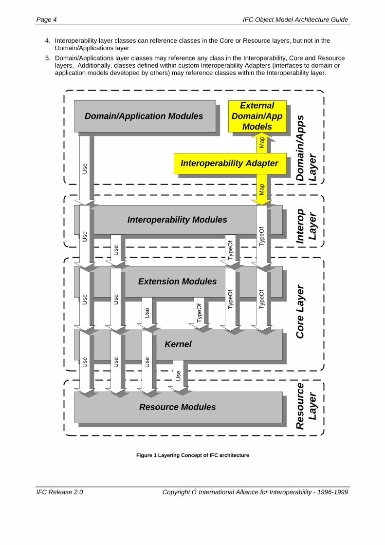
The IFC Object Model architecture provides a modular structure for the development of model components,the 'model schemas'. There are four conceptual layers within the architecture, which use a strict referencinghierarchy. Within each conceptual layer a set of model schemas is defined.
The first conceptual layer (shown at the bottom in Figure 1) provides Resource classes used by classes in thehigher levels. The second conceptual layer provides a Core project model. This Core contains the Kernel andseveral Core Extensions. The third conceptual layer provides a set of modules defining concepts or objectscommon across multiple application types or AEC industry domains. This is the Interoperability layer. Finally,the fourth and highest layer in the IFC Object Model is the Domain/Applications Layer. It provides set ofmodules tailored for specific AEC industry domain or application type. Additionally, this layer containsspecialized model 'adapters' to non-IFC domain/application models.
The architecture operates on a 'ladder principle'. At any layer, a class may reference a class at the same orlower layer but may not reference a class from a higher layer. References within the same layer must bedesigned very carefully in order to maintain modularity in the model design.
Inter-domain references at the Domain Models layer must be resolved through 'common concepts' defined inthe Interoperability layer. If possible, references between modules at the Resource layer should be avoided inorder to support the goal that each resource module is self-contained. However, there are some low level,general purpose resources, such as measurement and identification that are referenced by many otherresources.
Ladder principle expanded:
1. Resource classes may only reference or use other Resources.
2. Core classes may reference other Core classes (subject to the limitations listed in 3) and mayreference classes within the Resource layer without limitations. Core classes may not reference or useclasses within the Interoperability or Domain/Applications layer.
3. Within the Core layer the 'ladder principle' also applies. Therefore, Kernel classes can be referenced orused by classes in the Core Extensions but the reverse is not allowed. Kernel classes my notreference Core Extension classes.
Page 4 IFC Object Model Architecture Guide
IFC Release 2.0 Copyright International Alliance for Interoperability - 1996-1999
4. Interoperability layer classes can reference classes in the Core or Resource layers, but not in theDomain/Applications layer.
5. Domain/Applications layer classes may reference any class in the Interoperability, Core and Resourcelayers. Additionally, classes defined within custom Interoperability Adapters (interfaces to domain orapplication models developed by others) may reference classes within the Interoperability layer.
Interoperability Modules
Use
Extension Modules
Domain/Application Modules
Kernel
Co
re L
ayer
Res
ou
rce
Lay
erD
om
ain
/Ap
ps
Lay
er
Resource Modules
Typ
eOf
Use
Use
Use
Use
Use
Use
Use
Typ
eOf
Typ
eOf
Typ
eOf
Use
Use
Inte
rop
Lay
er
ExternalDomain/App
Models
Map
Interoperability Adapter
Map
Typ
eOf
Figure 1 Layering Concept of IFC architecture
IFC Object Model Architecture Guide Page 5
Copyright International Alliance for Interoperability - 1996-1999 IFC Release 2.0
3 IFC Model Architecture DecompositionThe current version of the IFC Model Architecture for Release consists of the following layers, each of whichwill be discussed in turn.
• Resource Layer• Core Layer
• Kernel• Extensions
• Interoperability Layer• Domain/Applications Layer
3.1 Resource Layer
Resources form the lowest layer in IFC Model Architecture and can be used orreferenced by classes in the other layers. Resources can be characterized as generalpurpose or low level concepts or objects which do not rely on any other classes in themodel for their existence. There are a few exceptions to this characterization. Classesfrom the Utility and Measure Resources are used by other, higher level resource classes.
All Resources represent individual business concepts. For instance, all informationconcerning the concept of cost is collected together within the cost schema, the IfcCostResource. Anyclasses within the Core, Interoperability or Domain/Application layers which need to use cost will referencethis resource.
Similarly, all ideas concerning geometry are collected together within the IfcGeometryResource.Fundamental geometric entity definitions are defined in this resource. More specialized attribute drivengeometry constructs are also defined here. Geometry will be referenced by classes defined within the Coreand higher levels through the representation resource, also provided at the resource layer. However somedetails within the IfcGeometryResource are hidden from classes in these higher layers. There is noimplication of choice for one of these representations coming from the resource layer, it simply provides thedefinition. A Core model object may utilize several geometry entities for representation.
3.1.1 Resource schemas for R1.5
Within the IFC Release 1.5 project scope the following resources schemas are included. Note that IFCRelease 1.0 included many of these resources.
• IfcUtilityResource (object identification, object history, general purpose tables)• IfcMeasureResource (units of measure, standard measurement types, custom measurement types)• IfcGeometryResource (attribute driven geometric representation items, explicit geometric representation
items, topological representation items, geometric models)• IfcPropertyTypeResource (fundamental property types, property type definitions, property sets, shape
representation)• IfcPropertyResource (extended property types: material, cost, actor, classification, time)
3.1.2 Resource schemas for R2.0
Within the IFC Release 2.0 project scope the following resource schemas are included. Note that IFCRelease 2.0 further elaborates the modularity and encapsulation of resource schemas
• IfcUtilityResource• IfcMeasureResource• IfcGeometryResource• IfcTopologyResource (was part of IfcGeometryResource in IFC Release 1.5)• IfcGeometricModelResource (was part of IfcGeometryResource in IFC Release 1.5)• IfcPropertyResource• IfcMaterialResource (was part of IfcPropertyResource in IFC Release 1.5)• IfcCostResource (was part of IfcPropertyResource in IFC Release 1.5)
UtilityResource
Page 6 IFC Object Model Architecture Guide
IFC Release 2.0 Copyright International Alliance for Interoperability - 1996-1999
• IfcActorResource (was part of IfcPropertyResource in IFC Release 1.5)• IfcClassificationResource (was part of IfcPropertyResource in IFC Release 1.5)• IfcDateAndTimeResource (was part of IfcPropertyResource in IFC Release 1.5)• IfcRepresentationResource (was part of IfcPropertyResource in IFC Release 1.5)
3.2 Core Layer
The Core forms the next layer in IFC Model Architecture. Classes defined here canbe referenced and specialized by all classes in the Interoperability and Domain/Application layers. The Core layer provides the basic structure of the IFC objectmodel and defines most abstract concepts that will be specialized by higher layers ofthe IFC object model.
The Core includes two levels of abstraction:
1. The Kernel
2. Core Extensions
Goals for Core Model Design:• definition of the common superset of those concepts that later can be refined and used by various
interoperability and domain models• pre-harmonization of domain models by providing this common superset• stable definition of the object model foundation to support upgrade compatible IFC Releases
3.2.1 Kernel
The Kernel provides all the basic concepts required for IFC models within the scope of the current IFCRelease. The Kernel also determines the model structure and decomposition. Concepts defined in the kernelare, necessarily, abstracted to a high level. The kernel also includes fundamental concepts concerning theprovision of objects, relationships, type definitions, attributes and roles. The Kernel can be envisioned as akind of Meta Model that provides the platform for all model extensions. The constructs that form the Kernelare very generic and are not AEC/FM specific, although they will only be used for AEC/FM purposes due tothe specialization by Core Extensions. The Kernel constructs will be included as a mandatory part of all IFCimplementations.
The Kernel is the foundation of the Core Model. Kernel classes may reference classes in the Resource layerbut may not reference those in the other parts of the Core or in higher level model layers. The use ofResources will be facilitated by well defined interfaces within resource schemata. Thus, the design detail forany particular resource will be hidden from referencing classes within the Kernel.
3.2.2 Core Extensions
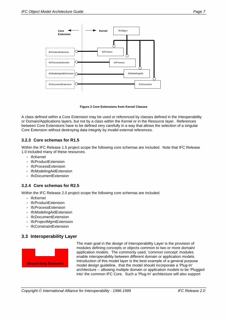
Core Extensions, as the name implies, provide extension or specialization of concepts defined in the Kernel.Core Extensions are therefore, the first refinement layer for abstract Kernel constructs. More specifically, theyextend Kernel constructs for use within the AEC/FM industry. Each Core Extension is a specialization ofclasses defined in the Kernel. Figure 2 shows the further specialization of classes rooted in the IfcKernel.
Beyond this class specialization, primary relationships and roles are also defined within the Core Extensions.
ProductExtension
IFC Object Model Architecture Guide Page 7
Copyright International Alliance for Interoperability - 1996-1999 IFC Release 2.0
IfcObject
IfcProcess
IfcProductIfcProductExtension
IfcProcessExtension
KernelCoreExtension
IfcModelingAid
IfcDocument
IfcModelingAidExtension
IfcDocumentExtension
Figure 2 Core Extensions from Kernel Classes
A class defined within a Core Extension may be used or referenced by classes defined in the Inteoperabilityor Domain/Applications layers, but not by a class within the Kernel or in the Resource layer. Referencesbetween Core Extensions have to be defined very carefully in a way that allows the selection of a singularCore Extension without destroying data integrity by invalid external references.
3.2.3 Core schemas for R1.5
Within the IFC Release 1.5 project scope the following core schemas are included. Note that IFC Release1.0 included many of these resources.
• IfcKernel• IfcProductExtension• IfcProcessExtension• IfcModelingAidExtension• IfcDocumentExtension
3.2.4 Core schemas for R2.5
Within the IFC Release 2.0 project scope the following core schemas are included.• IfcKernel• IfcProductExtension• IfcProcessExtension• IfcModelingAidExtension• IfcDocumentExtension• IfcProjectMgmtExtension• IfcConstraintExtension
3.3 Interoperability Layer
The main goal in the design of Interoperability Layer is the provision ofmodules defining concepts or objects common to two or more domain/application models. The commonly used, 'common concept' modulesenable interoperability between different domain or application models.Introduction of this model layer is the best example of a general purposemodel design guideline, that the model should incorporate a 'Plug-In'architecture -- allowing multiple domain or application models to be 'Pluggedinto' the common IFC Core. Such a 'Plug-In' architecture will also support
Shared Bldg Elements
Page 8 IFC Object Model Architecture Guide
IFC Release 2.0 Copyright International Alliance for Interoperability - 1996-1999
outsourcing the development of domain/application models.
3.3.1 Interoperability schemas for R1.5
Within the IFC Release 1.5 project scope the following schemas are defined in the Interoperability layer:• IfcSharedBldgElements (all fundamental building elements shared between domains)• IfcSharedBldgServiceElements ( all fundamental building service elements shared between domains)
3.3.2 Interoperability schemas for R2.0
Within the IFC Release 2.0 project scope the following schemas are defined in the Interoperability layer:• IfcSharedBldgElements• IfcSharedBldgServiceElements• IfcSharedSpatialElements
3.3.3 Adapter Definitions
Although not yet used in the current IFC Release the concept of an 'adapter' is foreseen to access variousdomain models, including disperse models (i.e. those defined outside the International Alliance forInteroperability). The main requirements for Adapters are the facilitation of:
1. Direct Plug-In of IFC developed Domain Models, that is a direct reference and use of Core definitionsby the appropriate Domain Models through the provision of interoperable class definitions at theInteroperability layer. This is currently the only applied technique.
2. Plug-In of externally developed, non harmonized, Domain Models via an Adapter that provides amapping mechanism down to Core and Interoperability definitions. The definition of the Adapter Plug isin the responsibility of the Domain Model developer and is part of the Domain Model Layer.
3. Establish an inter-domain exchange mechanism above the Core to enable interoperability acrossdomains. This includes a container mechanism to package information. Therefore an Adapter is usedwhere the definition of the Adapter is the responsibility of all Domain Models sharing this Adapter Plug.
The Adapters are based on Core Extension definitions and enhance those Core Extension definitions. Thoseenhancements provide common concepts for all Domain Models that might further refine these concepts. Asan example, the Building Element Socket provides the definition of a common wall, whereas the ArchitecturalDomain Model will enhance this common wall with its private subtypes and type definitions within Release 3.0time frame. An Adapter Socket that is used by several Domain Models therefore provides a medium level ofinteroperability through shared Adapter Socket definitions.
IFC Domain extensions that tightly couple with the Core Model such as those defined within the IFC Model(i.e., HVAC and Architecture) do not require an additional mapping of Domain Model definitions down to Coredefinitions, therefore they do not need specific Adapter.
Non-IFC harmonized models can be connected to the IFC Core Model through a mapping defined by aspecific Adapter. This methods needs to be further elaborated within the Release 3.0 time frame. For specifichigh-level inter-domain exchange, that cannot be satisfied by common definitions in the Core, the Adaptermay provide a specific inter-domain mapping. This Adapter type has to be developed within Release 3.0 timeframe as well.
3.4 Domain/Applications Layer
Domain/Applications Models provide further model detail within the scoperequirements for an AEC/FM domain process or a type of application. Each is aseparate model which may use or reference any class defined in the Core andIndependent Resource layers. Examples of Domain Models are Architecture, HVAC,FM, Structural Engineering etc. A main purpose of Domain Models is the provision ofspecialized type definitions that are tailored for the use within this domain.
Architecture
IFC Object Model Architecture Guide Page 9
Copyright International Alliance for Interoperability - 1996-1999 IFC Release 2.0
Part of the Domain Model definition is the definition of the Adapter Plugs if needed. Fully harmonized IFCDomain Models will be directly plugged in the Core definitions. Domain Models which are non fullyharmonized have to provide appropriate Adapter Plug definitions in order to be enabled to use the IFC modelframework. The Adapter Sockets provide the guidelines to develop those Plugs. If inter-domaininteroperability has to be achieved that extends the common shared Core definitions, those Domain Modeldevelopments have to be combined in order to provide an interoperable Plug.
3.4.1 Domain Models for R1.5
Within the IFC Release 1.5 project scope the following Domain Models are included:• IfcArchitecture• IfcFacilitiesMgmt
3.4.2 Domain Models for R2.0
Within the IFC Release 1.5 project scope the following Domain Models are included:• IfcArchitectureDomain• IfcFacilitiesMgmtDomain• IfcHVACDomain• IfcCostEstimatingDomain