Embed Size (px)
Citation preview
IFC 100IFC 100IFC 100IFC 100 Technical DatasheetTechnical DatasheetTechnical DatasheetTechnical Datasheet
Signal converter for electromagnetic flowmeters
• Simple and easy to install and start-up• Diagnostics of device and application• Extremely fast signal conversion
© KROHNE 07/2009 - 4000040503 - TD IFC 100 R03 en
The documentation is only complete when used in combination with the relevant documentation for the sensor.
.book Page 1 Friday, July 9, 2010 1:51 PM
CONTENTS
2 www.krohne.com 07/2009 - 4000040503 - TD IFC 100 R03 en
IFC 100
1 Product features 3
1.1 The more than economical solution ................................................................................ 31.2 Options and variants......................................................................................................... 51.3 Signal converter / measuring sensor combination possibilities..................................... 71.4 Measuring principle.......................................................................................................... 7
2 Technical data 8
2.1 Technical data................................................................................................................... 82.2 Dimensions and weights ................................................................................................ 14
2.2.1 Housing ................................................................................................................................. 142.2.2 Mounting plate, wall-mounted version ................................................................................ 17
2.3 Flow tables ..................................................................................................................... 182.4 Measuring accuracy ....................................................................................................... 20
3 Installation 21
3.1 Intended use ................................................................................................................... 213.2 Installation specifications .............................................................................................. 213.3 Mounting of the compact version................................................................................... 213.4 Mounting the wall-mounted housing, remote version .................................................. 22
3.4.1 Wall mounting ....................................................................................................................... 22
4 Electrical connections 24
4.1 Important notes on electrical connection...................................................................... 244.2 Preparing the signal and field current cables ............................................................... 24
4.2.1 Signal cable A (type DS 300), construction........................................................................... 244.2.2 Length of signal cable A........................................................................................................ 254.2.3 Connection diagram for signal and field current cable ....................................................... 26
4.3 Connecting the power..................................................................................................... 274.4 Overview of outputs ........................................................................................................ 29
4.4.1 Description of the CG number .............................................................................................. 294.4.2 Fixed, non-alterable output versions ................................................................................... 29
4.5 Laying electrical cables correctly .................................................................................. 30
5 Notes 31
.book Page 2 Friday, July 9, 2010 1:51 PM
PRODUCT FEATURES 1
3
IFC 100
www.krohne.com07/2009 - 4000040503 - TD IFC 100 R03 en
Product features
1.1 The more than economical solution
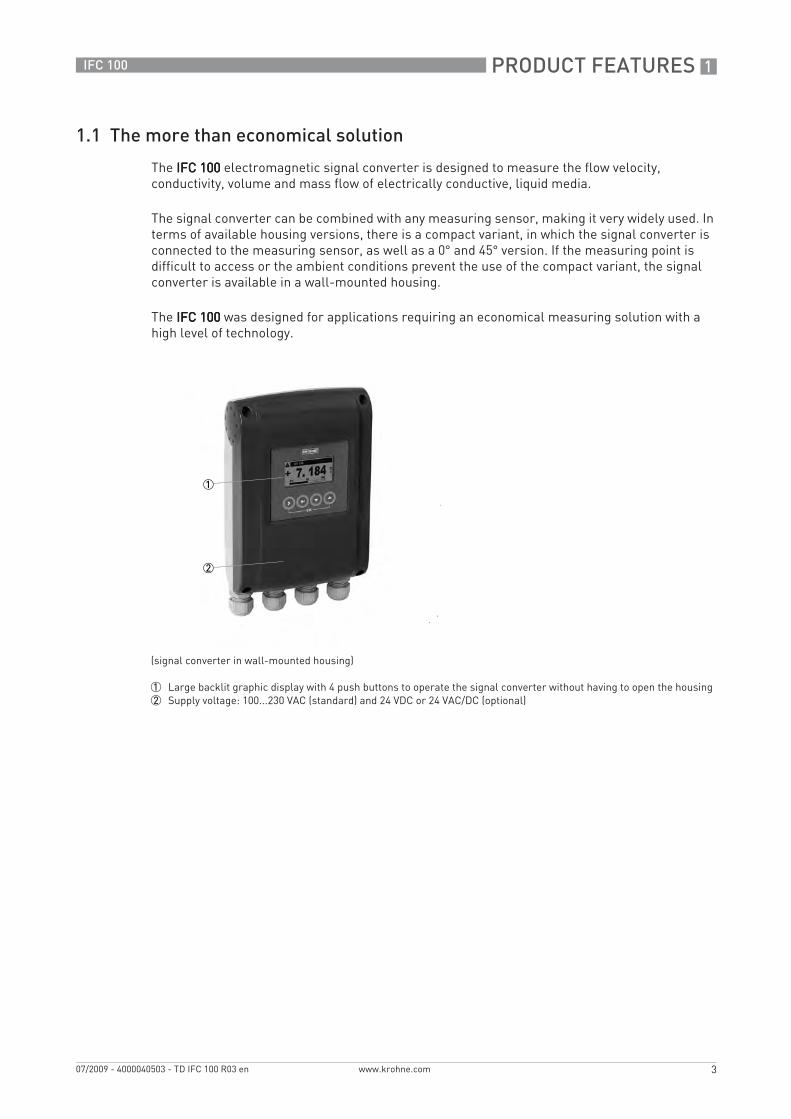
The IFC 100IFC 100IFC 100IFC 100 electromagnetic signal converter is designed to measure the flow velocity, conductivity, volume and mass flow of electrically conductive, liquid media.
The signal converter can be combined with any measuring sensor, making it very widely used. In terms of available housing versions, there is a compact variant, in which the signal converter is connected to the measuring sensor, as well as a 0° and 45° version. If the measuring point is difficult to access or the ambient conditions prevent the use of the compact variant, the signal converter is available in a wall-mounted housing.
The IFC 100IFC 100IFC 100IFC 100 was designed for applications requiring an economical measuring solution with a high level of technology.
(signal converter in wall-mounted housing)
1 Large backlit graphic display with 4 push buttons to operate the signal converter without having to open the housing2 Supply voltage: 100...230 VAC (standard) and 24 VDC or 24 VAC/DC (optional)
.book Page 3 Friday, July 9, 2010 1:51 PM

1 PRODUCT FEATURES
4
IFC 100
www.krohne.com 07/2009 - 4000040503 - TD IFC 100 R03 en
Highlights• Simple installation and start-up
• Available inputs and outputs: Current output (incl. HART®), pulse/frequency output, status output and control input
• Large backlit graphic display with intuitive operation• A variety of operating languages integrated as standard• Maintenance free• Excellent price/performance ratio• Extremely quick signal conversion
Industries• Water & Wastewater• Agriculture• Heating, Ventilation & Air Conditioning (HVAC)• Machinery• Power plants
Applications• Measuring homogeneous media• Water distribution networks and spray-irrigation systems• Water treatment• Environmental technology
.book Page 4 Friday, July 9, 2010 1:51 PM
PRODUCT FEATURES 1
5
IFC 100
www.krohne.com07/2009 - 4000040503 - TD IFC 100 R03 en
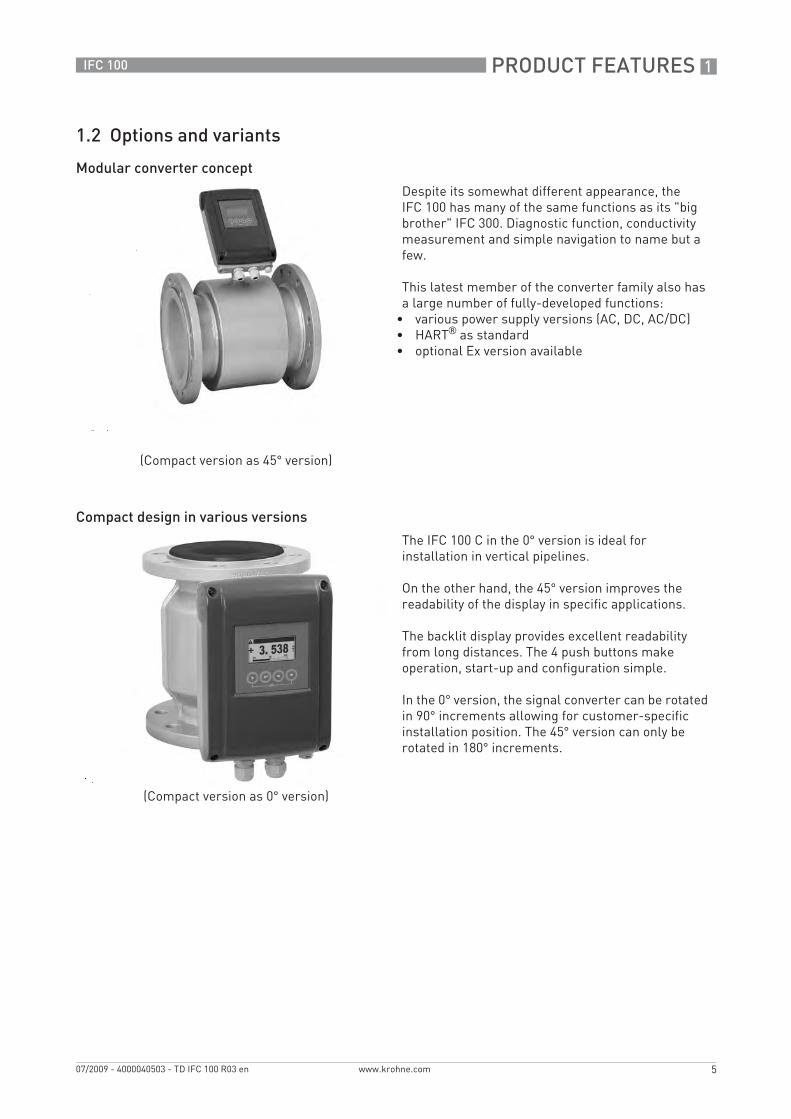
1.2 Options and variants
Modular converter concept
Compact design in various versions
(Compact version as 45° version)
Despite its somewhat different appearance, the IFC 100 has many of the same functions as its "big brother" IFC 300. Diagnostic function, conductivity measurement and simple navigation to name but a few.
This latest member of the converter family also has a large number of fully-developed functions:
• various power supply versions (AC, DC, AC/DC)• HART® as standard• optional Ex version available
(Compact version as 0° version)
The IFC 100 C in the 0° version is ideal for installation in vertical pipelines.
On the other hand, the 45° version improves the readability of the display in specific applications.
The backlit display provides excellent readability from long distances. The 4 push buttons make operation, start-up and configuration simple.
In the 0° version, the signal converter can be rotated in 90° increments allowing for customer-specific installation position. The 45° version can only be rotated in 180° increments.
.book Page 5 Friday, July 9, 2010 1:51 PM

1 PRODUCT FEATURES
6
IFC 100
www.krohne.com 07/2009 - 4000040503 - TD IFC 100 R03 en
Remote version in wall-mounted housing
Diagnostics
(signal converter in wall-mounted housing)
For temperature effects, vibration or in places that are difficult to access, remote installation is possible with the IFC 100 W.
A signal cable is used to connect the measuring sensor and the converter for the purposes of power supply and signal processing.
The electronics can be used in all housing versions without having to be reconfigurated.
The IFC 100 has been equipped with a wide variety of diagnostic tools for device function and application check.
• Conductivity measurement• Electrode error• Process or ambient temperature too high
.book Page 6 Friday, July 9, 2010 1:51 PM
PRODUCT FEATURES 1
7
IFC 100
www.krohne.com07/2009 - 4000040503 - TD IFC 100 R03 en
1.3 Signal converter / measuring sensor combination possibilities
1.4 Measuring principle
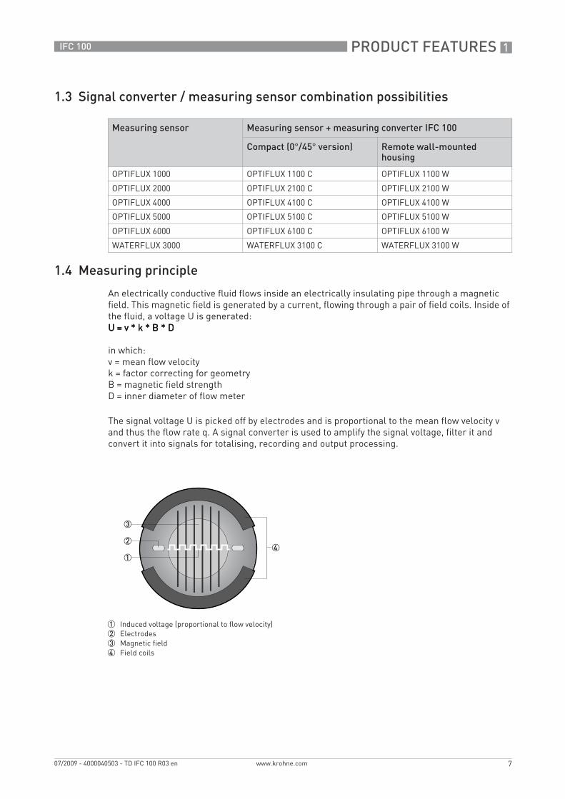
An electrically conductive fluid flows inside an electrically insulating pipe through a magnetic field. This magnetic field is generated by a current, flowing through a pair of field coils. Inside of the fluid, a voltage U is generated:U = v * k * B * DU = v * k * B * DU = v * k * B * DU = v * k * B * D
in which:v = mean flow velocityk = factor correcting for geometryB = magnetic field strengthD = inner diameter of flow meter
The signal voltage U is picked off by electrodes and is proportional to the mean flow velocity v and thus the flow rate q. A signal converter is used to amplify the signal voltage, filter it and convert it into signals for totalising, recording and output processing.
Measuring sensor Measuring sensor + measuring converter IFC 100
Compact (0°/45° version) Remote wall-mounted housing
OPTIFLUX 1000 OPTIFLUX 1100 C OPTIFLUX 1100 W
OPTIFLUX 2000 OPTIFLUX 2100 C OPTIFLUX 2100 W
OPTIFLUX 4000 OPTIFLUX 4100 C OPTIFLUX 4100 W
OPTIFLUX 5000 OPTIFLUX 5100 C OPTIFLUX 5100 W
OPTIFLUX 6000 OPTIFLUX 6100 C OPTIFLUX 6100 W
WATERFLUX 3000 WATERFLUX 3100 C WATERFLUX 3100 W
1 Induced voltage (proportional to flow velocity)2 Electrodes3 Magnetic field4 Field coils
.book Page 7 Friday, July 9, 2010 1:51 PM
2 TECHNICAL DATA
8
IFC 100
www.krohne.com 07/2009 - 4000040503 - TD IFC 100 R03 en
Technical data
2.1 Technical data
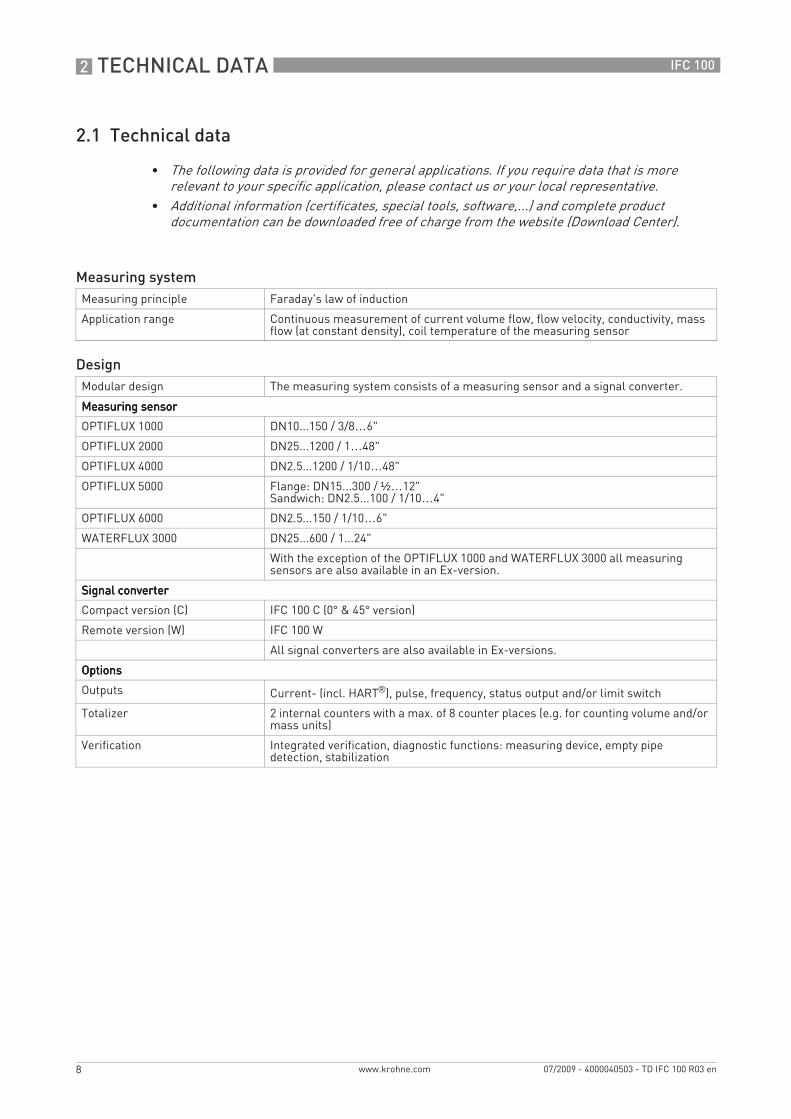
• The following data is provided for general applications. If you require data that is more relevant to your specific application, please contact us or your local representative.
• Additional information (certificates, special tools, software,...) and complete product documentation can be downloaded free of charge from the website (Download Center).
Measuring systemMeasuring principle Faraday's law of induction
Application range Continuous measurement of current volume flow, flow velocity, conductivity, mass flow (at constant density), coil temperature of the measuring sensor
DesignModular design The measuring system consists of a measuring sensor and a signal converter.
Measuring sensorMeasuring sensorMeasuring sensorMeasuring sensor
OPTIFLUX 1000 DN10...150 / 3/8…6"
OPTIFLUX 2000 DN25...1200 / 1…48"
OPTIFLUX 4000 DN2.5...1200 / 1/10…48"
OPTIFLUX 5000 Flange: DN15...300 / ½…12"Sandwich: DN2.5...100 / 1/10…4"
OPTIFLUX 6000 DN2.5...150 / 1/10…6"
WATERFLUX 3000 DN25...600 / 1...24"
With the exception of the OPTIFLUX 1000 and WATERFLUX 3000 all measuring sensors are also available in an Ex-version.
Signal converterSignal converterSignal converterSignal converter
Compact version (C) IFC 100 C (0° & 45° version)
Remote version (W) IFC 100 W
All signal converters are also available in Ex-versions.
OptionsOptionsOptionsOptions
Outputs Current- (incl. HART®), pulse, frequency, status output and/or limit switch
Totalizer 2 internal counters with a max. of 8 counter places (e.g. for counting volume and/or mass units)
Verification Integrated verification, diagnostic functions: measuring device, empty pipe detection, stabilization
.book Page 8 Friday, July 9, 2010 1:51 PM
TECHNICAL DATA 2
9
IFC 100
www.krohne.com07/2009 - 4000040503 - TD IFC 100 R03 en
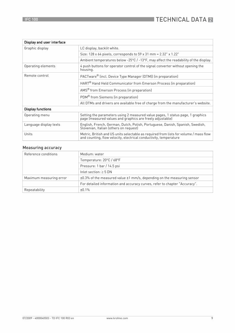
Display and user interfaceDisplay and user interfaceDisplay and user interfaceDisplay and user interface
Graphic display LC display, backlit white.
Size: 128 x 64 pixels, corresponds to 59 x 31 mm = 2.32" x 1.22"
Ambient temperatures below -25°C / -13°F, may affect the readability of the display.
Operating elements 4 push buttons for operator control of the signal converter without opening the housing.
Remote control PACTware® (incl. Device Type Manager (DTM)) (in preparation)
HART® Hand Held Communicator from Emerson Process (in preparation)
AMS® from Emerson Process (in preparation)
PDM® from Siemens (in preparation)
All DTMs and drivers are available free of charge from the manufacturer's website.
Display functionsDisplay functionsDisplay functionsDisplay functions
Operating menu Setting the parameters using 2 measured value pages, 1 status page, 1 graphics page (measured values and graphics are freely adjustable)
Language display texts English, French, German, Dutch, Polish, Portuguese, Danish, Spanish, Swedish, Slovenian, Italian (others on request)
Units Metric, British and US units selectable as required from lists for volume / mass flow and counting, flow velocity, electrical conductivity, temperature
Measuring accuracyReference conditions Medium: water
Temperature: 20°C / 68°F
Pressure: 1 bar / 14.5 psi
Inlet section: ≥ 5 DN
Maximum measuring error ±0.3% of the measured value ±1 mm/s, depending on the measuring sensor
For detailed information and accuracy curves, refer to chapter "Accuracy".
Repeatability ±0.1%
.book Page 9 Friday, July 9, 2010 1:51 PM
2 TECHNICAL DATA
10
IFC 100
www.krohne.com 07/2009 - 4000040503 - TD IFC 100 R03 en
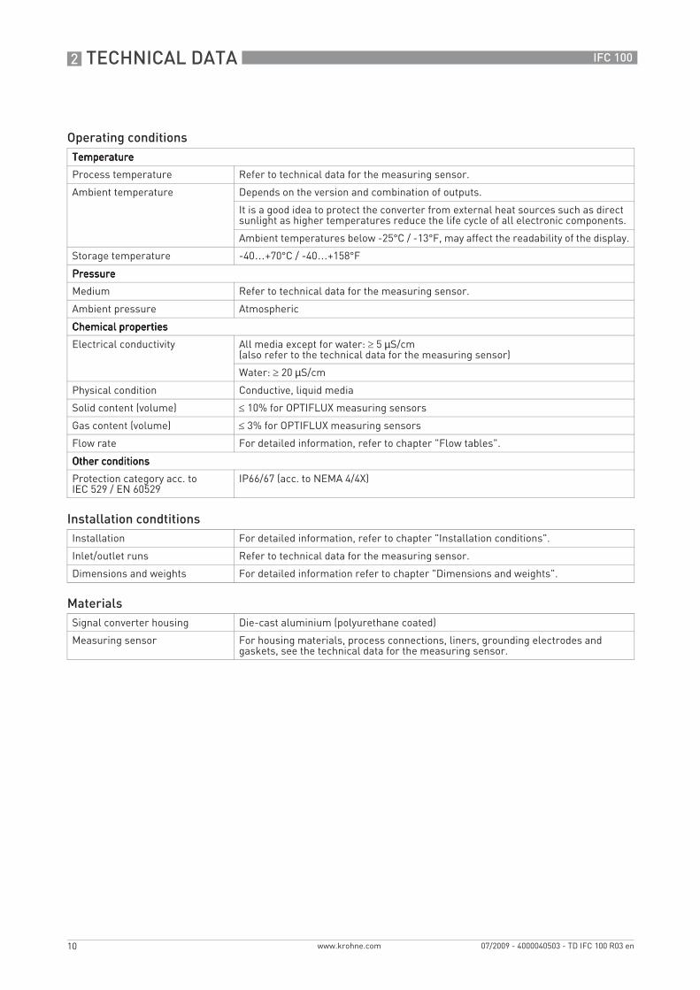
Operating conditionsTemperatureTemperatureTemperatureTemperature
Process temperature Refer to technical data for the measuring sensor.
Ambient temperature Depends on the version and combination of outputs.
It is a good idea to protect the converter from external heat sources such as direct sunlight as higher temperatures reduce the life cycle of all electronic components.
Ambient temperatures below -25°C / -13°F, may affect the readability of the display.
Storage temperature -40…+70°C / -40…+158°F
PressurePressurePressurePressure
Medium Refer to technical data for the measuring sensor.
Ambient pressure Atmospheric
Chemical propertiesChemical propertiesChemical propertiesChemical properties
Electrical conductivity All media except for water: ≥ 5 µS/cm(also refer to the technical data for the measuring sensor)
Water: ≥ 20 µS/cm
Physical condition Conductive, liquid media
Solid content (volume) ≤ 10% for OPTIFLUX measuring sensors
Gas content (volume) ≤ 3% for OPTIFLUX measuring sensors
Flow rate For detailed information, refer to chapter "Flow tables".
Other conditionsOther conditionsOther conditionsOther conditions
Protection category acc. to IEC 529 / EN 60529
IP66/67 (acc. to NEMA 4/4X)
Installation condtitionsInstallation For detailed information, refer to chapter "Installation conditions".
Inlet/outlet runs Refer to technical data for the measuring sensor.
Dimensions and weights For detailed information refer to chapter "Dimensions and weights".
MaterialsSignal converter housing Die-cast aluminium (polyurethane coated)
Measuring sensor For housing materials, process connections, liners, grounding electrodes and gaskets, see the technical data for the measuring sensor.
.book Page 10 Friday, July 9, 2010 1:51 PM

TECHNICAL DATA 2
11
IFC 100
www.krohne.com07/2009 - 4000040503 - TD IFC 100 R03 en
Electrical connectionGeneral Electrical connection is carried out in conformity with the VDE 0100 directive
"Regulations for electrical power installations with line voltages up to 1000 V" or equivalent national regulations.
Power supply 100…230 VAC (-15% / +10%), 50/60 Hz; non-Ex: standard; Ex: optional240 VAC + 5% is included in the tolerance range.
12...24 VDC (-55% / +30%); only available in non Ex version12 VDC - 10% is included in the tolerance range.
24 VAC/DC (AC: -15% / +10%; DC: -25% / +30%); only available as Ex version12 V is notnotnotnot included in the tolerance range.
Power consumption AC: 7 VA
DC: 4 W
Signal cable Only necessary for remote device versions.
DS 300 (type A)DS 300 (type A)DS 300 (type A)DS 300 (type A)Max. length: 600 m / 1950 ft (depending on electrical conductivity and version of measuring sensor)
Cable entries Standard: M20 x 1.5 (8...12 mm)
Option: ½" NPT, PF ½
OutputsGeneral All outputs are electrically isolated from each other and from all other circuits.
All operating data and output values can be adjusted.
Description of used abbreviations Uext = external voltage; RL = load + resistance;Uo = terminal voltage; Inom = nominal current
Current outputCurrent outputCurrent outputCurrent output
Output data Volume flow, mass flow, diagnostics value, flow velocity, coil temperature, conductivity
Settings Without HARTWithout HARTWithout HARTWithout HART®
Q = 0%: 0…20 mA; Q = 100%: 10…21.5 mA
Error identification: 0…22 mA
With HARTWith HARTWith HARTWith HART®
Q = 0%: 4…20 mA; Q = 100%: 10…21.5 mA
Error identification: 3.5…22 mA
Operating dataOperating dataOperating dataOperating data
Active Uint, nom = 20 VDC
I ≤ 22 mA
RL ≤ 750 Ω
Passive Uext ≤ 32 VDC
I ≤ 22 mA
U0 ≤ 2 V at I = 22 mA
RL ≤ (Uext - U0) / Imax
.book Page 11 Friday, July 9, 2010 1:51 PM
2 TECHNICAL DATA
12
IFC 100
www.krohne.com 07/2009 - 4000040503 - TD IFC 100 R03 en
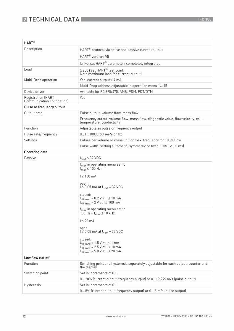
HARTHARTHARTHART®
Description HART® protocol via active and passive current output
HART® version: V5
Universal HART® parameter: completely integrated
Load ≥ 250 Ω at HART® test point;Note maximum load for current output!
Multi-Drop operation Yes, current output = 4 mA
Multi-Drop address adjustable in operation menu 1…15
Device driver Available for FC 375/475, AMS, PDM, FDT/DTM
Registration (HART Communication Foundation)
Yes
Pulse or frequency outputPulse or frequency outputPulse or frequency outputPulse or frequency output
Output data Pulse output: volume flow, mass flow
Frequency output: volume flow, mass flow, diagnostic value, flow velocity, coil temperature, conductivity
Function Adjustable as pulse or frequency output
Pulse rate/frequency 0.01...10000 pulses/s or Hz
Settings Pulses per volume or mass unit or max. frequency for 100% flow
Pulse width: setting automatic, symmetric or fixed (0.05...2000 ms)
Operating dataOperating dataOperating dataOperating data
Passive Uext ≤ 32 VDC
fmax in operating menu set to fmax ≤ 100 Hz:
I ≤ 100 mA
open:I ≤ 0.05 mA at Uext = 32 VDC
closed:U0, max = 0.2 V at I ≤ 10 mAU0, max = 2 V at I ≤ 100 mA
fmax in operating menu set to100 Hz < fmax ≤ 10 kHz:
I ≤ 20 mA
open:I ≤ 0.05 mA at Uext = 32 VDC
closed:U0, max = 1.5 V at I ≤ 1 mAU0, max = 2.5 V at I ≤ 10 mAU0, max = 5.0 V at I ≤ 20 mA
Low flow cut-offLow flow cut-offLow flow cut-offLow flow cut-off
Function Switching point and hysteresis separately adjustable for each output, counter and the display
Switching point Set in increments of 0.1.
0…20% (current output, frequency output) or 0...±9.999 m/s (pulse output)
Hysteresis Set in increments of 0.1.
0…5% (current output, frequency output) or 0…5 m/s (pulse output)
.book Page 12 Friday, July 9, 2010 1:51 PM

TECHNICAL DATA 2
13
IFC 100
www.krohne.com07/2009 - 4000040503 - TD IFC 100 R03 en
Time constantTime constantTime constantTime constant
Function The time constant corresponds to the elapsed time until 67% of the end value has been reached according to a step function.
Settings Set in increments of 0.1.
0…100 s
Status output / limit switchStatus output / limit switchStatus output / limit switchStatus output / limit switch
Function and settings Adjustable as automatic measuring range conversion, display of flow direction, counter overflow, error, switching point or empty pipe detection
Valve control with activated dosing function
Status and/or control: ON or OFF
Operating dataOperating dataOperating dataOperating data
Passive Uext ≤ 32 VDC
I ≤ 100 mA
open:I ≤ 0.05 mA at Uext = 32 VDC
closed:U0, max = 0.2 V at I ≤ 10 mAU0, max = 2 V at I ≤ 100 mA
Modbus (in preparation)Modbus (in preparation)Modbus (in preparation)Modbus (in preparation)
Description Modbus RTU, Master / Slave, RS485
Address range 1…247
Broadcast Supported with function code 16
Supported Baudrate 1200, 2400, 4800, 9600, 19200, 38400, 57600, 115200 Baud
Approvals and certificatesCE The device fulfils the statutory requirements of the EC directives. The manufacturer
certifies that these requirements have been met by applying the CE marking.
Non-Ex Standard
Hazardous areasHazardous areasHazardous areasHazardous areas
ATEX Optional (OPTIFLUX 2100 C and OPTIFLUX 4100 C only)Optional (OPTIFLUX 2100 C and OPTIFLUX 4100 C only)Optional (OPTIFLUX 2100 C and OPTIFLUX 4100 C only)Optional (OPTIFLUX 2100 C and OPTIFLUX 4100 C only)
II 2 G Ex e [ia] mb IIC T4 (DN10...20; DN200...300; DN350...3000)
II 2 G Ex d e [ia] mb IIC T4 (DN25...150)
II 2 G Ex e [ia] mb q T4/T3 (DN25...150; DN200...300)
II 2 D Ex tD A21 IP64 T120°C (all nominal sizes)
Option (only version W)Option (only version W)Option (only version W)Option (only version W)
II 2 G Ex e [ia] mb IIC T4
II 2 D Ex tD A21 IP64 T135°C
Other standards and approvalsOther standards and approvalsOther standards and approvalsOther standards and approvals
Shock and vibration resistance IEC 68-2-3
Electromagnetic compatibility (EMC)
2004/108/EC in conjunction with EN 61326-1 (A1, A2)
European Pressure Equipment Directive
PED 97/23 (only for compact versions)
NAMUR NE 21, NE 43, NE 53
.book Page 13 Friday, July 9, 2010 1:51 PM
2 TECHNICAL DATA
14
IFC 100
www.krohne.com 07/2009 - 4000040503 - TD IFC 100 R03 en
2.2 Dimensions and weights
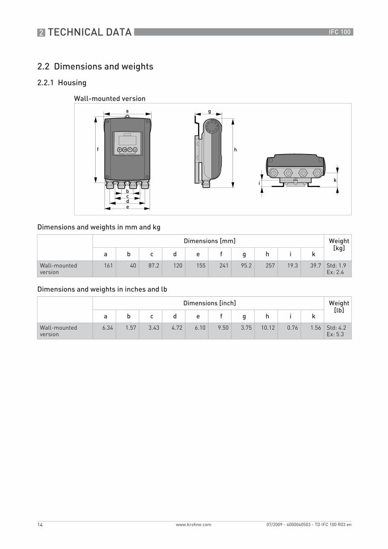
2.2.1 Housing
Dimensions and weights in mm and kg
Dimensions and weights in inches and lb
Wall-mounted version
Dimensions [mm] Weight [kg]
a b c d e f g h i k
Wall-mounted version
161 40 87.2 120 155 241 95.2 257 19.3 39.7 Std: 1.9Ex: 2.4
Dimensions [inch] Weight [lb]
a b c d e f g h i k
Wall-mounted version
6.34 1.57 3.43 4.72 6.10 9.50 3.75 10.12 0.76 1.56 Std: 4.2Ex: 5.3
.book Page 14 Friday, July 9, 2010 1:51 PM
TECHNICAL DATA 2
15
IFC 100
www.krohne.com07/2009 - 4000040503 - TD IFC 100 R03 en
Dimensions and weights in mm and kg
Dimensions and weights in inches and lb
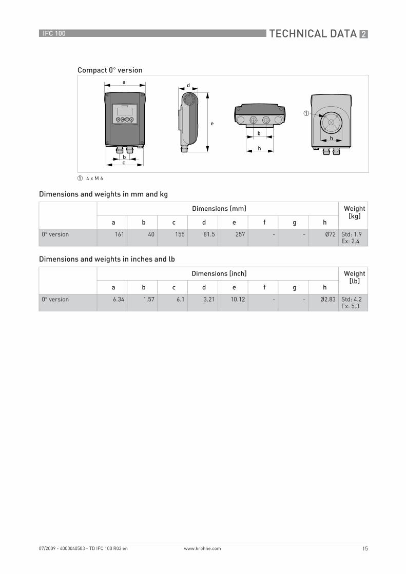
Compact 0° version
1 4 x M 6
Dimensions [mm] Weight [kg]
a b c d e f g h
0° version 161 40 155 81.5 257 - - Ø72 Std: 1.9Ex: 2.4
Dimensions [inch] Weight [lb]
a b c d e f g h
0° version 6.34 1.57 6.1 3.21 10.12 - - Ø2.83 Std: 4.2Ex: 5.3
.book Page 15 Friday, July 9, 2010 1:51 PM
2 TECHNICAL DATA
16
IFC 100
www.krohne.com 07/2009 - 4000040503 - TD IFC 100 R03 en
Dimensions and weights in mm and kg
Dimensions and weights in inches and lb
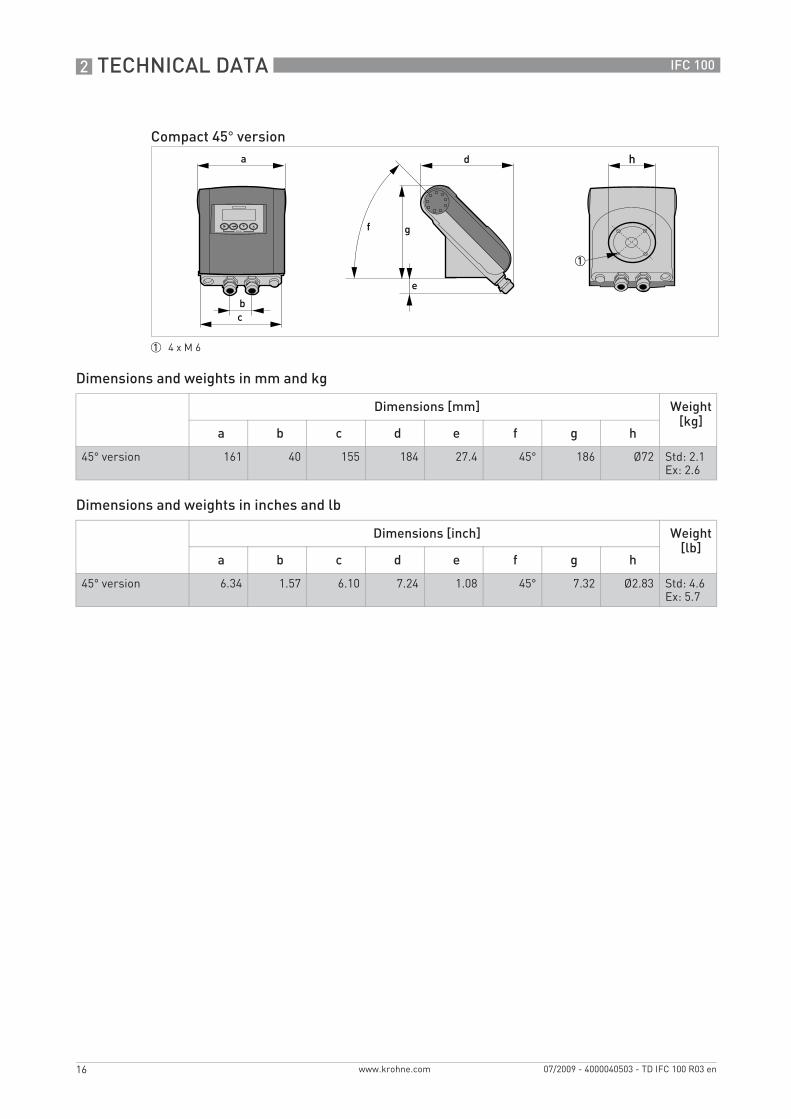
Compact 45° version
1 4 x M 6
Dimensions [mm] Weight [kg]
a b c d e f g h
45° version 161 40 155 184 27.4 45° 186 Ø72 Std: 2.1Ex: 2.6
Dimensions [inch] Weight [lb]
a b c d e f g h
45° version 6.34 1.57 6.10 7.24 1.08 45° 7.32 Ø2.83 Std: 4.6Ex: 5.7
.book Page 16 Friday, July 9, 2010 1:51 PM
TECHNICAL DATA 2
17
IFC 100
www.krohne.com07/2009 - 4000040503 - TD IFC 100 R03 en
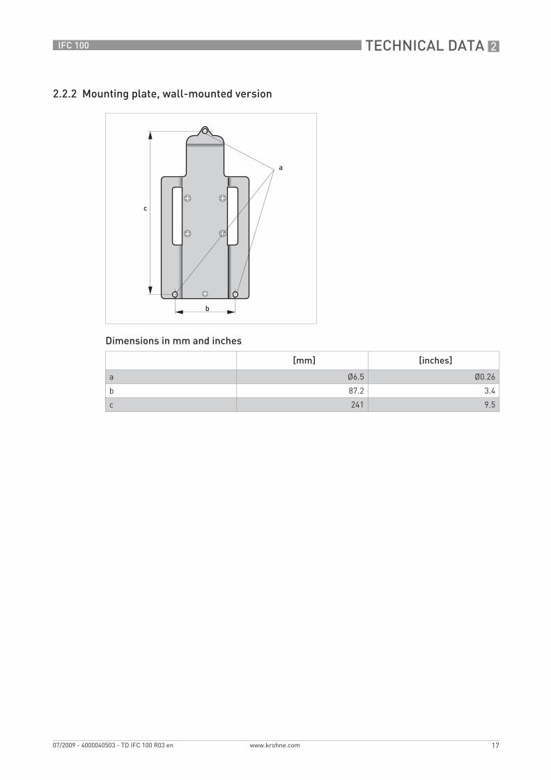
2.2.2 Mounting plate, wall-mounted version
Dimensions in mm and inches
[mm] [inches]
a Ø6.5 Ø0.26
b 87.2 3.4
c 241 9.5
.book Page 17 Friday, July 9, 2010 1:51 PM

2 TECHNICAL DATA
18
IFC 100
www.krohne.com 07/2009 - 4000040503 - TD IFC 100 R03 en
2.3 Flow tables
Flow rate in m/s and m3/h
Q100 % in m3/h
v [m/s] 0.3 1 3 12
DN [mm] Min. flow Nominal flow Max. flow
2.5 0.005 0.02 0.05 0.21
4 0.01 0.05 0.14 0.54
6 0.03 0.10 0.31 1.22
10 0.08 0.28 0.85 3.39
15 0.19 0.64 1.91 7.63
20 0.34 1.13 3.39 13.57
25 0.53 1.77 5.30 21.21
32 0.87 2.90 8.69 34.74
40 1.36 4.52 13.57 54.29
50 2.12 7.07 21.21 84.82
65 3.58 11.95 35.84 143.35
80 5.43 18.10 54.29 217.15
100 8.48 28.27 84.82 339.29
125 13.25 44.18 132.54 530.15
150 19.09 63.62 190.85 763.40
200 33.93 113.10 339.30 1357.20
250 53.01 176.71 530.13 2120.52
300 76.34 254.47 763.41 3053.64
350 103.91 346.36 1039.08 4156.32
400 135.72 452.39 1357.17 5428.68
450 171.77 572.51 1717.65 6870.60
500 212.06 706.86 2120.58 8482.32
600 305.37 1017.90 3053.70 12214.80
700 415.62 1385.40 4156.20 16624.80
800 542.88 1809.60 5428.80 21715.20
900 687.06 2290.20 6870.60 27482.40
1000 848.22 2827.40 8482.20 33928.80
1200 1221.45 3421.20 12214.50 48858.00
.book Page 18 Friday, July 9, 2010 1:51 PM
TECHNICAL DATA 2
19
IFC 100
www.krohne.com07/2009 - 4000040503 - TD IFC 100 R03 en
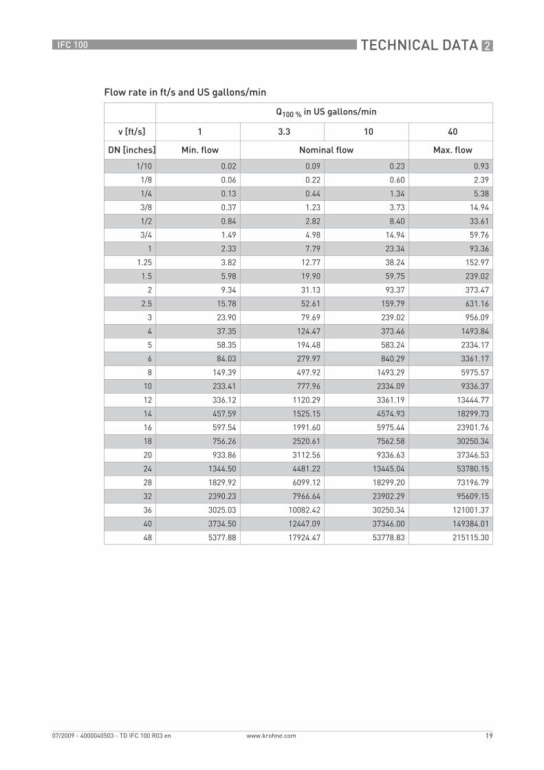
Flow rate in ft/s and US gallons/min
Q100 % in US gallons/min
v [ft/s] 1 3.3 10 40
DN [inches] Min. flow Nominal flow Max. flow
1/10 0.02 0.09 0.23 0.93
1/8 0.06 0.22 0.60 2.39
1/4 0.13 0.44 1.34 5.38
3/8 0.37 1.23 3.73 14.94
1/2 0.84 2.82 8.40 33.61
3/4 1.49 4.98 14.94 59.76
1 2.33 7.79 23.34 93.36
1.25 3.82 12.77 38.24 152.97
1.5 5.98 19.90 59.75 239.02
2 9.34 31.13 93.37 373.47
2.5 15.78 52.61 159.79 631.16
3 23.90 79.69 239.02 956.09
4 37.35 124.47 373.46 1493.84
5 58.35 194.48 583.24 2334.17
6 84.03 279.97 840.29 3361.17
8 149.39 497.92 1493.29 5975.57
10 233.41 777.96 2334.09 9336.37
12 336.12 1120.29 3361.19 13444.77
14 457.59 1525.15 4574.93 18299.73
16 597.54 1991.60 5975.44 23901.76
18 756.26 2520.61 7562.58 30250.34
20 933.86 3112.56 9336.63 37346.53
24 1344.50 4481.22 13445.04 53780.15
28 1829.92 6099.12 18299.20 73196.79
32 2390.23 7966.64 23902.29 95609.15
36 3025.03 10082.42 30250.34 121001.37
40 3734.50 12447.09 37346.00 149384.01
48 5377.88 17924.47 53778.83 215115.30
.book Page 19 Friday, July 9, 2010 1:51 PM
2 TECHNICAL DATA
20
IFC 100
www.krohne.com 07/2009 - 4000040503 - TD IFC 100 R03 en
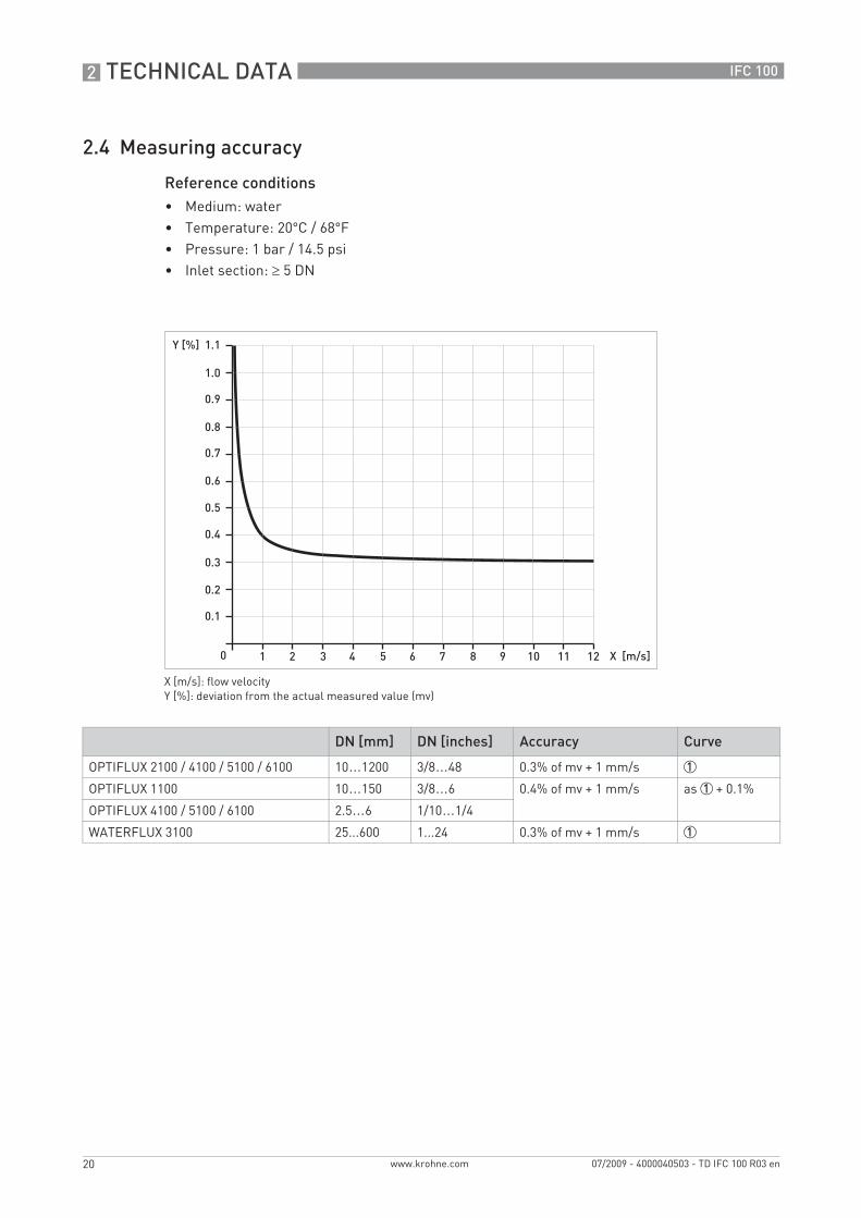
2.4 Measuring accuracy
Reference conditions• Medium: water• Temperature: 20°C / 68°F• Pressure: 1 bar / 14.5 psi• Inlet section: ≥ 5 DN
X [m/s]: flow velocityY [%]: deviation from the actual measured value (mv)
DN [mm] DN [inches] Accuracy Curve
OPTIFLUX 2100 / 4100 / 5100 / 6100 10…1200 3/8…48 0.3% of mv + 1 mm/s 1
OPTIFLUX 1100 10…150 3/8…6 0.4% of mv + 1 mm/s as 1 + 0.1%
OPTIFLUX 4100 / 5100 / 6100 2.5…6 1/10…1/4
WATERFLUX 3100 25...600 1...24 0.3% of mv + 1 mm/s 1
.book Page 20 Friday, July 9, 2010 1:51 PM

INSTALLATION 3
21
IFC 100
www.krohne.com07/2009 - 4000040503 - TD IFC 100 R03 en
Installation
3.1 Intended use
The electromagnetic flowmeters are designed exclusively to measure the flow and conductivity of electrically conductive, liquid media.
3.2 Installation specifications
3.3 Mounting of the compact version
For devices used in hazardous areas, additional safety notes apply; please refer to the Ex documentation.
If the device is not used according to the operating conditions (refer to chapter "Technical data), the intended protection could be affected.
The following precautions must be taken to ensure reliable installation.• Make sure that there is adequate space to the sides.• Protect the signal converter from direct sunlight and install a sun shade if necessary.• Signal converters installed in control cabinets require adequate cooling, e.g. by fan or heat
exchanger.• Do not expose the signal converter to intense vibration. The flowmeters are tested for a
vibration level in accordance with IEC 68-2-3.
The signal converter is mounted directly on the measuring sensor. For installation of the flowmeter, please observe the instructions in the supplied product documentation for the measuring sensor.
.book Page 21 Friday, July 9, 2010 1:51 PM

3 INSTALLATION
22
IFC 100
www.krohne.com 07/2009 - 4000040503 - TD IFC 100 R03 en
3.4 Mounting the wall-mounted housing, remote version
3.4.1 Wall mounting
1 Prepare the holes with the aid of the mounting plate. For further information refer to Mounting plate, wall-mounted version on page 17.
2 Fasten the device securely to the wall with the mounting plate.
Assembly materials and tools are not part of the delivery. Use the assembly materials and tools in compliance with the applicable occupational health and safety directives.
Figure 3-1: Mounting the wall-mounted housing
.book Page 22 Friday, July 9, 2010 1:51 PM
INSTALLATION 3
23
IFC 100
www.krohne.com07/2009 - 4000040503 - TD IFC 100 R03 en
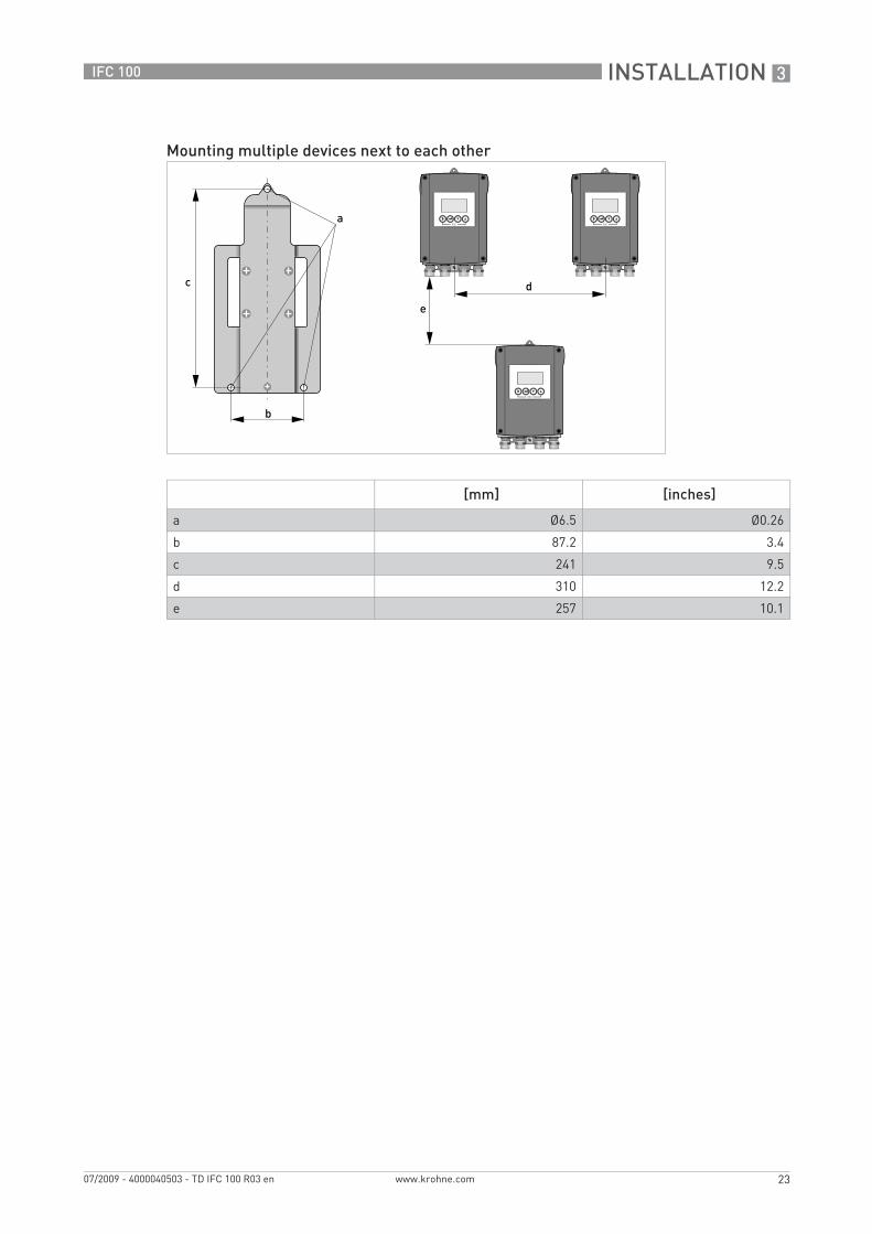
Mounting multiple devices next to each other
[mm] [inches]
a Ø6.5 Ø0.26
b 87.2 3.4
c 241 9.5
d 310 12.2
e 257 10.1
.book Page 23 Friday, July 9, 2010 1:51 PM

4 ELECTRICAL CONNECTIONS
24
IFC 100
www.krohne.com 07/2009 - 4000040503 - TD IFC 100 R03 en
Electrical connections
4.1 Important notes on electrical connection
4.2 Preparing the signal and field current cables
4.2.1 Signal cable A (type DS 300), construction
• Signal cable A is a double-shielded cable for signal transmission between the measuring sensor and signal converter.
• Bending radius: ≥ 50 mm / 2"
Electrical connection is carried out in conformity with the VDE 0100 directive "Regulations for electrical power installations with line voltages up to 1000 V" or equivalent national regulations.
• Use suitable cable entries for the various electrical cables.• The sensor and converter are configured together in the factory. For this reason, please
connect the devices in pairs. Ensure that the sensor constant GK/GKL (see type plates) are identically set.
• If delivered separately or when installing devices that were not configured together, set the converter to the DN size and GK/GKL of the sensor.
Assembly materials and tools are not part of the delivery. Use the assembly materials and tools in compliance with the applicable occupational health and safety directives.
Figure 4-1: Construction of signal cable A
1 Stranded drain wire (1) for the inner shield (10), 1.0 mm2 Cu / AWG 17 (not insulated, bare)
2 Insulated wire (2), 0.5 mm2 Cu / AWG 20
3 Insulated wire (3), 0.5 mm2 Cu / AWG 204 Outer sheath5 Insulation layers6 Stranded drain wire (6) for the outer shield (60)
.book Page 24 Friday, July 9, 2010 1:51 PM

ELECTRICAL CONNECTIONS 4
25
IFC 100
www.krohne.com07/2009 - 4000040503 - TD IFC 100 R03 en
4.2.2 Length of signal cable A
For temperatures of the medium above 150°C / 300°F, a special signal cable and a ZD intermediate socket are necessary. These are available including the changed electrical connection diagrams.
Measuring sensor Nominal size Min. electrical conductivity[µS/cm]
Curve for signal cable A
DN [mm] [inches]
OPTIFLUX 1000 F 10...150 3/8...6 5 A1
OPTIFLUX 2000 F 25...150 1...6 20 A1
200...1200 8...48 20 A2
OPTIFLUX 4000 F 2.5...150 1/10...6 1 A1
200...1200 8...48 1 A2
OPTIFLUX 5000 F 2.5...100 1/10...4 1 A1
150...250 6...10 1 A2
OPTIFLUX 6000 F 2.5...150 1/10...6 1 A1
WATERFLUX 3000 F 25...600 1...24 20 A1
Figure 4-2: Maximum length of signal cable A
1 Maximum length of signal cable A between the measuring sensor and signal converter [m]2 Maximum length of signal cable A between the measuring sensor and signal converter [ft]3 Electrical conductivity of the medium being measured [μS/cm]
.book Page 25 Friday, July 9, 2010 1:51 PM
4 ELECTRICAL CONNECTIONS
26
IFC 100
www.krohne.com 07/2009 - 4000040503 - TD IFC 100 R03 en
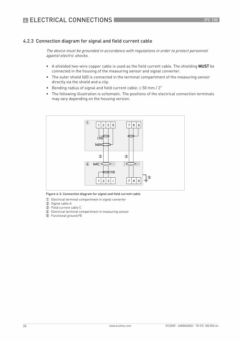
4.2.3 Connection diagram for signal and field current cable
• A shielded two-wire copper cable is used as the field current cable. The shielding MUSTMUSTMUSTMUST be connected in the housing of the measuring sensor and signal converter.
• The outer shield (60) is connected in the terminal compartment of the measuring sensor directly via the shield and a clip.
• Bending radius of signal and field current cable: ≥ 50 mm / 2"• The following illustration is schematic. The positions of the electrical connection terminals
may vary depending on the housing version.
The device must be grounded in accordance with regulations in order to protect personnel against electric shocks.
Figure 4-3: Connection diagram for signal and field current cable
1 Electrical terminal compartment in signal converter2 Signal cable A3 Field current cable C4 Electrical terminal compartment in measuring sensor5 Functional ground FE
.book Page 26 Friday, July 9, 2010 1:51 PM
ELECTRICAL CONNECTIONS 4
27
IFC 100
www.krohne.com07/2009 - 4000040503 - TD IFC 100 R03 en
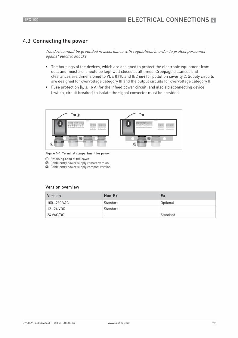
4.3 Connecting the power
• The housings of the devices, which are designed to protect the electronic equipment from dust and moisture, should be kept well closed at all times. Creepage distances and clearances are dimensioned to VDE 0110 and IEC 664 for pollution severity 2. Supply circuits are designed for overvoltage category III and the output circuits for overvoltage category II.
• Fuse protection (IN ≤ 16 A) for the infeed power circuit, and also a disconnecting device (switch, circuit breaker) to isolate the signal converter must be provided.
Version overview
The device must be grounded in accordance with regulations in order to protect personnel against electric shocks.
Figure 4-4: Terminal compartment for power
1 Retaining band of the cover2 Cable entry power supply remote version3 Cable entry power supply compact version
Version Non-Ex Ex
100...230 VAC Standard Optional
12...24 VDC Standard -
24 VAC/DC - Standard
.book Page 27 Friday, July 9, 2010 1:51 PM

4 ELECTRICAL CONNECTIONS
28
IFC 100
www.krohne.com 07/2009 - 4000040503 - TD IFC 100 R03 en
• Open the cover of the electrical terminal compartment by pressing down and pulling forwards at the same time.
• Close the cover after the power has been connected.
100...230 VAC (tolerance range: -15% / +10%)100...230 VAC (tolerance range: -15% / +10%)100...230 VAC (tolerance range: -15% / +10%)100...230 VAC (tolerance range: -15% / +10%)• Note the power supply voltage and frequency (50...60 Hz) on the nameplate.
12...24 VDC (tolerance range: -55% / +30%)12...24 VDC (tolerance range: -55% / +30%)12...24 VDC (tolerance range: -55% / +30%)12...24 VDC (tolerance range: -55% / +30%)• Note the data on the nameplate!• When connecting to functional extra-low voltages, provide a facility for protective separation
(PELV) (acc. to VDE 0100 / VDE 0106 and IEC 364 / IEC 536 or relevant national regulations).
24 VAC/DC (tolerance range: AC: -15% / +10%; DC: -25% / +30%)24 VAC/DC (tolerance range: AC: -15% / +10%; DC: -25% / +30%)24 VAC/DC (tolerance range: AC: -15% / +10%; DC: -25% / +30%)24 VAC/DC (tolerance range: AC: -15% / +10%; DC: -25% / +30%)• AC: Note the power supply voltage and frequency (50...60 Hz) on the nameplate.• DC: When connecting to functional extra-low voltages, provide a facility for protective
separation (PELV) (acc. to VDE 0100 / VDE 0106 and IEC 364 / IEC 536 or relevant national regulations).
Figure 4-5: Power supply connection
1 100...230 VAC (-15% / +10%), 8 VA2 24 VDC (-55% / +30%), 4 W3 24 VAC/DC (AC: -15% / +10%; DC: -25% / +30%), 7 VA and 4 W
240 VAC + 5% is included in the tolerance range.
12 VDC - 10% is included in the tolerance range.
12 V is notnotnotnot included in the tolerance range.
.book Page 28 Friday, July 9, 2010 1:51 PM
ELECTRICAL CONNECTIONS 4
29
IFC 100
www.krohne.com07/2009 - 4000040503 - TD IFC 100 R03 en
4.4 Overview of outputs
4.4.1 Description of the CG number
4.4.2 Fixed, non-alterable output versions
This signal converter is available with various output combinations.
• The grey boxes in the tables denote unassigned or unused connection terminals.• In the table, only the final digits of the CG-No. are depicted.• Connection terminal A+ is only operable in the basic output version.
Description of used abbreviations
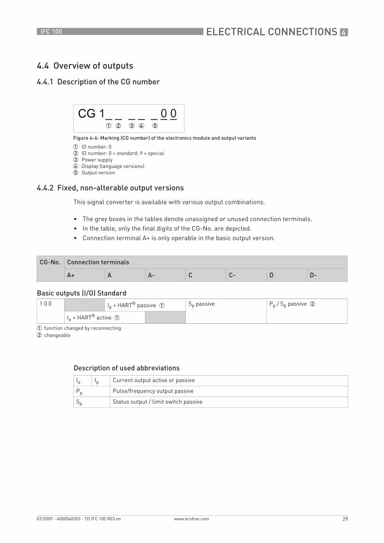
Figure 4-6: Marking (CG number) of the electronics module and output variants
1 ID number: 02 ID number: 0 = standard; 9 = special3 Power supply4 Display (language versions)5 Output version
CG-No. Connection terminals
A+ A A- C C- D D-
Basic outputs (I/O) Standard1 0 0 Ip + HART® passive 1 Sp passive Pp / Sp passive 2
Ia + HART® active 1
1 function changed by reconnecting2 changeable
Ia Ip Current output active or passive
Pp Pulse/frequency output passive
Sp Status output / limit switch passive
.book Page 29 Friday, July 9, 2010 1:51 PM
4 ELECTRICAL CONNECTIONS
30
IFC 100
www.krohne.com 07/2009 - 4000040503 - TD IFC 100 R03 en
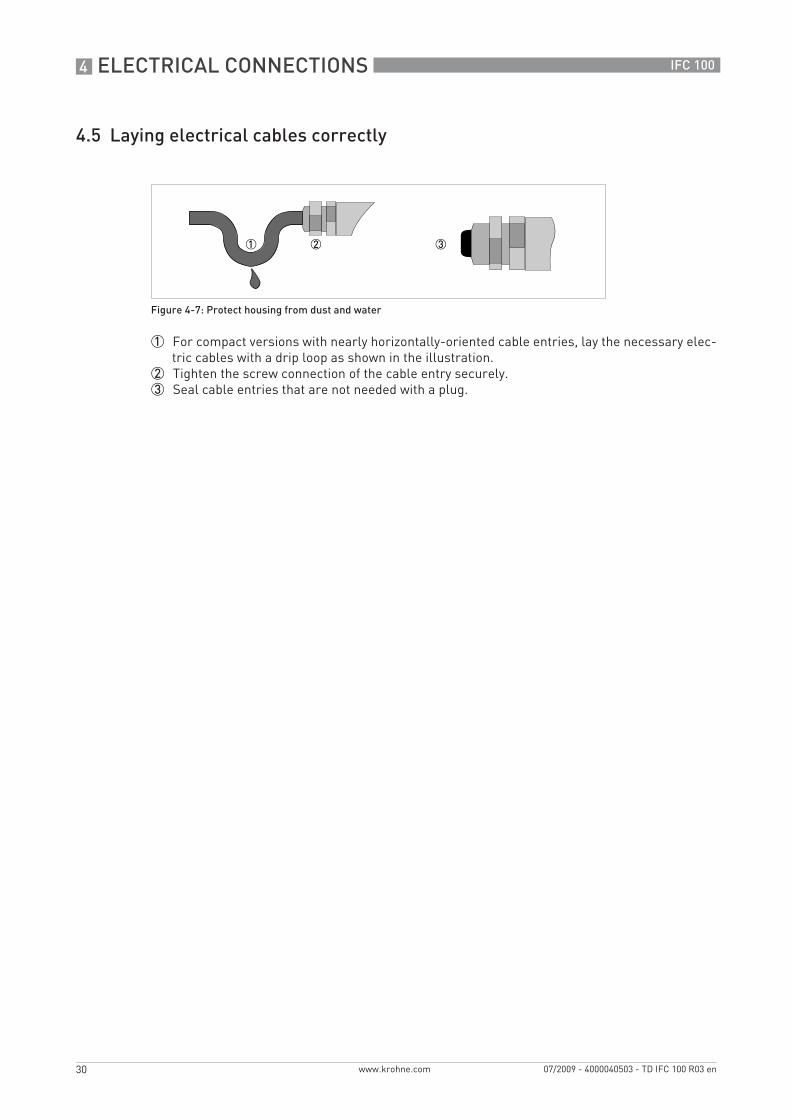
4.5 Laying electrical cables correctly
1 For compact versions with nearly horizontally-oriented cable entries, lay the necessary elec-tric cables with a drip loop as shown in the illustration.
2 Tighten the screw connection of the cable entry securely.3 Seal cable entries that are not needed with a plug.
Figure 4-7: Protect housing from dust and water
.book Page 30 Friday, July 9, 2010 1:51 PM
NOTES 5
31
IFC 100
www.krohne.com07/2009 - 4000040503 - TD IFC 100 R03 en
Notes
.book Page 31 Friday, July 9, 2010 1:51 PM

KROHNE product overview
• Electromagnetic flowmeters
• Variable area flowmeters
• Ultrasonic flowmeters
• Mass flowmeters
• Vortex flowmeters
• Flow controllers
• Level meters
• Temperature meters
• Pressure meters
• Analysis products
• Measuring systems for the oil and gas industry
• Measuring systems for sea-going tankers
Head Office KROHNE Messtechnik GmbHLudwig-Krohne-Str. 5D-47058 Duisburg (Germany)Tel.:+49 (0)203 301 0Fax:+49 (0)203 301 10389 [email protected]
© K
RO
HN
E 07
/200
9 -
4000
0405
03 -
TD
IFC
100
R03
en
- Su
bjec
t to
chan
ge w
ithou
t not
ice.
The current list of all KROHNE contacts and addresses can be found at:www.krohne.com
KK
K
.book Page 32 Friday, July 9, 2010 1:51 PM