Embed Size (px)
Citation preview

IFC 050IFC 050IFC 050IFC 050 Technical DatasheetTechnical DatasheetTechnical DatasheetTechnical Datasheet
Signal converter for electromagnetic flowmeters
• For simple applications• Multiple outputs, incl. active pulse output and RS485 Modbus• Excellent price/performance ratio
© KROHNE 09/2016 - 4002183703 - TD IFC 050 R03 en
The documentation is only complete when used in combination with the relevant documentation for the flow sensor.

CONTENTS
2 www.krohne.com 09/2016 - 4002183703 - TD IFC 050 R03 en
IFC 050
1 Product features 3
1.1 The standard for simple applications .............................................................................. 31.2 Options and variants......................................................................................................... 51.3 Signal converter/flow sensor combination possibilities ................................................. 61.4 Measuring principle.......................................................................................................... 6
2 Technical data 7
2.1 Technical data................................................................................................................... 72.2 Dimensions and weight .................................................................................................. 14
2.2.1 Housing ................................................................................................................................. 142.2.2 Mounting plate, wall version................................................................................................. 16
2.3 Flow tables ..................................................................................................................... 172.4 Measuring accuracy ....................................................................................................... 19
3 Installation 20
3.1 Intended use ................................................................................................................... 203.2 Installation specifications .............................................................................................. 203.3 Mounting of the compact version................................................................................... 203.4 Mounting of the wall housing, remote version .............................................................. 20
4 Electrical connections 22
4.1 Safety instructions.......................................................................................................... 224.2 Preparing the signal and field current cables ............................................................... 22
4.2.1 Signal cable A (type DS 300), construction........................................................................... 224.2.2 Length of signal cable A........................................................................................................ 234.2.3 Connection diagram for signal and field current cable ....................................................... 24
4.3 Grounding the flow sensor ............................................................................................. 254.4 Connecting the power supply......................................................................................... 254.5 Inputs and outputs, overview ......................................................................................... 27
4.5.1 Description of the CG number .............................................................................................. 274.5.2 Fixed, non-alterable output versions ................................................................................... 27
4.6 Laying electrical cables correctly .................................................................................. 28
5 Notes 29

PRODUCT FEATURES 1
3
IFC 050
www.krohne.com09/2016 - 4002183703 - TD IFC 050 R03 en
1.1 The standard for simple applications
The electromagnetic signal converter IFC 050IFC 050IFC 050IFC 050 is a perfect choice for measuring volumetric flow in various kinds of applications in the water industry but also in the food and beverage business.
The signal converter can be combined with the flow sensors OPTIFLUX 1000, 2000, 4000, 6000 and the WATERFLUX 3000. The output represents measured values for flow, mass and conductivity.
This low-cost signal converter has some specific features:• An active pulse output for a simple system, like driving an electro-mechanical counter• RS485 Modbus communication with a data processing system• Extra insulation of the electronic device and housing for high performance in areas with
extreme humidity and chances for flooding• Cost-effective flow measurement for a wide range of process conditions and still a very
acceptable degree of accuracy
1 Large graphic display with 4 magnet keys for operating the signal converter when the housing is closed2 4 push buttons to operate the signal converter when the housing is open3 Supply voltage: 100…230 VAC and 24 VDC

1 PRODUCT FEATURES
4
IFC 050
www.krohne.com 09/2016 - 4002183703 - TD IFC 050 R03 en
Highlights
• Available outputs: current output (incl. HART®), active pulse/frequency output, status output and Modbus
• Intuitive operation with touch buttons• Excellent price/performance ratio• Modern robust housing design• Asymmetric mounting possible• All versions with and without display are available• Simple installation and start-up• Bright graphic display• A variety of operating languages integrated as standard• Certified tests for humidity and vibration• Extremely quick signal conversion
Industries• Water & Wastewater• Food & Beverage• Heating, Ventilation & Air Conditioning (HVAC)• Agriculture• Steel
Applications• Water and wastewater treatment• Water distribution network• Irrigation installation• Water abstraction• CIP cleaning stations

PRODUCT FEATURES 1
5
IFC 050
www.krohne.com09/2016 - 4002183703 - TD IFC 050 R03 en
1.2 Options and variants
Modular signal converter concept with display
Remote version in wall housing with display
Remote version in wall housing without display
The modular concept gives the opportunity to combine the IFC 050 with the flow sensors OPTIFLUX 1000, OPTIFLUX 2000, OPTIFLUX 4000, OPTIFLUX 6000 and the WATERFLUX 3000.With respect to the housing versions, both a compact and a remote design are available. The signal converter for the compact version is directly mounted under a 10° angle to the flow sensor for easy reading of the display after rainfall or frost.
If the measuring point is difficult to access or if the ambient conditions like temperature effects and vibration prevent the use of the compact version, a remote signal converter with a wall housing is available.
A signal cable is used to connect the flow sensor to the signal converter for power supply and signal processing.The same electronic unit can be used in both (Compact + Wall) versions without configuration.
A blind version is the perfect option in a situation where the display is not required and the menu will be approached once a time.A separate display can be easily connected to the electronic unit to enter the menu. This tool will be provided as a spare part.

1 PRODUCT FEATURES
6
IFC 050
www.krohne.com 09/2016 - 4002183703 - TD IFC 050 R03 en
1.3 Signal converter/flow sensor combination possibilities
1.4 Measuring principle
An electrically conductive fluid flows inside an electrically insulated pipe through a magnetic field. This magnetic field is generated by a current, flowing through a pair of field coils.Inside of the fluid, a voltage U is generated:U = v * k * B * DU = v * k * B * DU = v * k * B * DU = v * k * B * D
in which:v = mean flow velocityk = factor correcting for geometryB = magnetic field strengthD = inner diameter of flowmeter
The signal voltage U is picked off by electrodes and is proportional to the mean flow velocity v and thus the flow rate Q. A signal converter is used to amplify the signal voltage, filter it and convert it into signals for totalizing, recording and output processing.
Flow sensor Flow sensor + signal converter IFC 050
Compact Remote wall-mounted housing
OPTIFLUX 1000 OPTIFLUX 1050 C OPTIFLUX 1050 W
OPTIFLUX 2000 OPTIFLUX 2050 C OPTIFLUX 2050 W
OPTIFLUX 4000 OPTIFLUX 4050 C OPTIFLUX 4050 W
OPTIFLUX 6000 OPTIFLUX 6050 C OPTIFLUX 6050 W
WATERFLUX 3000 WATERFLUX 3050 C WATERFLUX 3050 W
Figure 1-1: Measuring principle
1 Field coils2 Magnetic field3 Electrodes4 Induced voltage (proportional to flow velocity)

TECHNICAL DATA 2
7
IFC 050
www.krohne.com09/2016 - 4002183703 - TD IFC 050 R03 en
2.1 Technical data
• The following data is provided for general applications. If you require data that is more relevant to your specific application, please contact us or your local sales office.
• Additional information (certificates, special tools, software,...) and complete product documentation can be downloaded free of charge from the website (Downloadcenter).
Measuring systemMeasuring principle Faraday's law of induction
Application range Continuous measurement of current volume flow, flow velocity, conductivity, mass flow (at constant density), coil temperature of the flow sensor
DesignModular construction The measuring system consists of a flow sensor and a signal converter.
Flow sensorFlow sensorFlow sensorFlow sensor
OPTIFLUX 1000 DN10...150 / 3/8…6"
OPTIFLUX 2000 DN25...1200 / 1…48"
OPTIFLUX 4000 DN10...1200 / 3/8…48"
OPTIFLUX 6000 DN10...150 / 3/8...6"
WATERFLUX 3000 DN25...600 / 1…24"
Signal converterSignal converterSignal converterSignal converter
Compact version (C) IFC 050 C
Remote version (W) IFC 050 W
OptionsOptionsOptionsOptions
Outputs Current output (incl. HART®), pulse output, frequency output, status output and/or limit switch
Note: It's not possible to use the pulse/frequency output with the status output at the same time!
Counter 2 internal counters with a max. of 10 counter places (e.g. for counting volume and/or mass units)
Verification Integrated verification, diagnostic functions: measuring device, empty pipe detection, stabilisation
Communication interfaces HART®
Modbus

2 TECHNICAL DATA
8
IFC 050
www.krohne.com 09/2016 - 4002183703 - TD IFC 050 R03 en
Display and user interfaceDisplay and user interfaceDisplay and user interfaceDisplay and user interface
Graphic display LC display, backlit white
Size: 128 x 64 pixels, corresponds to 59 x 31 mm = 2.32" x 1.22"
Ambient temperatures below -25°C / -13°F may affect the readability of the display.
Operating elements 4 push buttons for operating the signal converter when the housing is open.
4 magnet keys for operating the signal converter when the housing is closed.
Remote control Only generic and not device-specific DDs and DTMs available!
PACTwareTM (including Device Type Manager (DTM))
HART® Hand Held Communicator from Emerson Process
AMS® from Emerson Process
PDM® from Siemens
All DTMs and drivers are available free of charge from the manufacturer's website.
Display functionsDisplay functionsDisplay functionsDisplay functions
Operating menu Setting the parameters using 2 measuring pages, 1 status page, 1 graphic page (measured values and graphics are freely adjustable)
Language display texts (as language package)
Standard: English, French, German, Dutch, Portuguese, Swedish, Spanish, Italian
Eastern Europe: English, Slovenian, Czech, Hungarian
Northern Europe: English, Danish, Polish, Finnish
Southern Europe: English, Turkish
China: English, German, Chinese
Russia: English, German, Russian
Units Metric, British and US units selectable as required from lists for volume / mass flow and counting, flow velocity, electrical conductivity, temperature
Measuring accuracyMax. measuring accuracy Standard:Standard:Standard:Standard:
±0.5% of the measured value ± 1 mm/s
Option (optimised accuracy with extended calibration):Option (optimised accuracy with extended calibration):Option (optimised accuracy with extended calibration):Option (optimised accuracy with extended calibration):±0.25% of the measured value ± 1.5 mm/s
For detailed information and accuracy curves refer to Measuring accuracy on page 19.
Special calibrations are available on request.
Current output electronics: ±10 µA; ±100 ppm/°C (typically: ±30 ppm/°C)
Repeatability ±0.1%

TECHNICAL DATA 2
9
IFC 050
www.krohne.com09/2016 - 4002183703 - TD IFC 050 R03 en
Operating conditionsTemperatureTemperatureTemperatureTemperature
Process temperature Refer to technical data for the flow sensor.
Ambient temperature Depending on the version and combination of outputs.
It is a good idea to protect the converter from external heat sources such as direct sunlight as higher temperatures reduce the life cycle of all electronic components.
Ambient temperatures below -25°C / -13°F may affect the readability of the display.
Storage temperature -40…+70°C / -40…+158°F
PressurePressurePressurePressure
Medium Refer to technical data for the flow sensor.
Ambient pressure Atmosphere
Chemical propertiesChemical propertiesChemical propertiesChemical properties
Electrical conductivity All media except for water: ≥ 5 µS/cm(also refer to the technical data for the flow sensor)
Water: ≥ 20 µS/cm
State of aggregation Conductive, liquid media
Solid content (volume) ≤ 10%
Gas content (volume) ≤ 3%
Flow rate For detailed information, refer to chapter "Flow tables".
Other conditionsOther conditionsOther conditionsOther conditions
Ingress protection acc. to IEC 529 / EN 60529
IP66/67 (acc. to NEMA 4/4X)
Installation conditionsInstallation For detailed information, refer to chapter "Installation conditions".
Inlet / outlet sections Refer to technical data for the flow sensor.
Dimensions and weight For detailed information refer to chapter "Dimensions and weight".
MaterialsSignal converter housing Aluminum with a polyester topcoat
Flow sensor For housing materials, process connections, liners, grounding electrodes and gaskets, refer to technical data for the flow sensor.
2 TECHNICAL DATA
10
IFC 050
www.krohne.com 09/2016 - 4002183703 - TD IFC 050 R03 en
Electrical connectionGeneral Electrical connection is carried out in conformity with the VDE 0100 directive
"Regulations for electrical power installations with line voltages up to 1000 V" or equivalent national specifications.
Power supply 100…230 VAC (-15% / +10%), 50/60 Hz;240 VAC + 5% is included in the tolerance range.
24 VDC (-30% / +30%)
Power consumption AC: 15 VA
DC: 5.6 W
Signal cable Only necessary for remote versions.
DS 300 (type A)DS 300 (type A)DS 300 (type A)DS 300 (type A)Max. length: 600 m / 1968 ft (depending on electrical conductivity and flow sensor version)
Cable entries Standard: M20 x 1.5 (8...12 mm)
Option: ½ NPT, PF ½
OutputsGeneral All outputs are electrically isolated from each other and from all other circuits.
All operating data and output values can be adjusted.
Description of abbreviations Uext = external voltage; RL = load + resistance;Uo = terminal voltage; Inom = nominal current

TECHNICAL DATA 2
11
IFC 050
www.krohne.com09/2016 - 4002183703 - TD IFC 050 R03 en
Current outputCurrent outputCurrent outputCurrent output
Output data Flow
Settings Without HARTWithout HARTWithout HARTWithout HART®
Q = 0%: 0…20 mA; Q = 100%: 10…21.5 mA
Error identification: 20…22 mA
With HARTWith HARTWith HARTWith HART®
Q = 0%: 4…20 mA; Q = 100%: 10…21.5 mA
Error identification: 3…22 mA
Operating dataOperating dataOperating dataOperating data Basic I/OsBasic I/OsBasic I/OsBasic I/Os
Active Observe connection polarity.
Uint, nom = 20 VDC
I ≤ 22 mA
RL ≤ 750 Ω
HART® at terminals A
Passive Observe connection polarity.
Uext ≤ 32 VDC
I ≤ 22 mA
U0 ≤ 2 V at I = 22 mA
RL, max = (Uext - U0) / Imax
HART® at terminals A
HARTHARTHARTHART®
Description HART® protocol via active and passive current output
HART® version: V5
Universal Common Practice HART® parameter: completely supported
Load ≥ 250 Ω at HART® test point;Note maximum load for current output!
Multi-drop mode Yes, current output = 4 mA
Multi-drop address adjustable in operation menu 1…15

2 TECHNICAL DATA
12
IFC 050
www.krohne.com 09/2016 - 4002183703 - TD IFC 050 R03 en
Pulse or frequency outputPulse or frequency outputPulse or frequency outputPulse or frequency output
Output data Flow
Function Can be set as a pulse output or frequency output
Pulse rate/frequency 0.01...10000 pulses/s or Hz
Settings Pulses per volume or mass unit or max. frequency for 100% flow
Pulse width: adjustable as automatic, symmetric or fixed (0.05...2000 ms)
Operating dataOperating dataOperating dataOperating data Basic I/Os + ModbusBasic I/Os + ModbusBasic I/Os + ModbusBasic I/Os + Modbus
Active This output is intended to drive mechanical or electronic counters directly.
Uint, nom ≤ 20 V
RV = 1 kΩ
C = 1000 µF
High current mechanical counterHigh current mechanical counterHigh current mechanical counterHigh current mechanical counterfmax ≤ 1 Hz
Low current mechanical counterLow current mechanical counterLow current mechanical counterLow current mechanical counterI ≤ 20 mA
RL ≤ 10 kΩ for f ≤ 1 kHzRL ≤ 1 kΩ for f ≤ 10 kHz
closed:U0 ≥ 12.5 V at I = 10 mA
open:I ≤ 0.05 mA at Unom = 20 V
Passive Independent of connection polarity.
Uext ≤ 32 VDC
fmax in operating menu set to fmax ≤ 100 Hz:
I ≤ 100 mA
open:I ≤ 0.05 mA at Uext = 32 VDC
closed:U0, max = 0.2 V at I ≤ 10 mAU0, max = 2 V at I ≤ 100 mA
fmax in operating menu set to 100 Hz < fmax ≤ 10 kHz:
I ≤ 20 mA
open:I ≤ 0.05 mA at Uext = 32 VDC
closed:U0, max = 1.5 V at I ≤ 1 mAU0, max = 2.5 V at I ≤ 10 mAU0, max = 5.0 V at I ≤ 20 mA
TECHNICAL DATA 2
13
IFC 050
www.krohne.com09/2016 - 4002183703 - TD IFC 050 R03 en
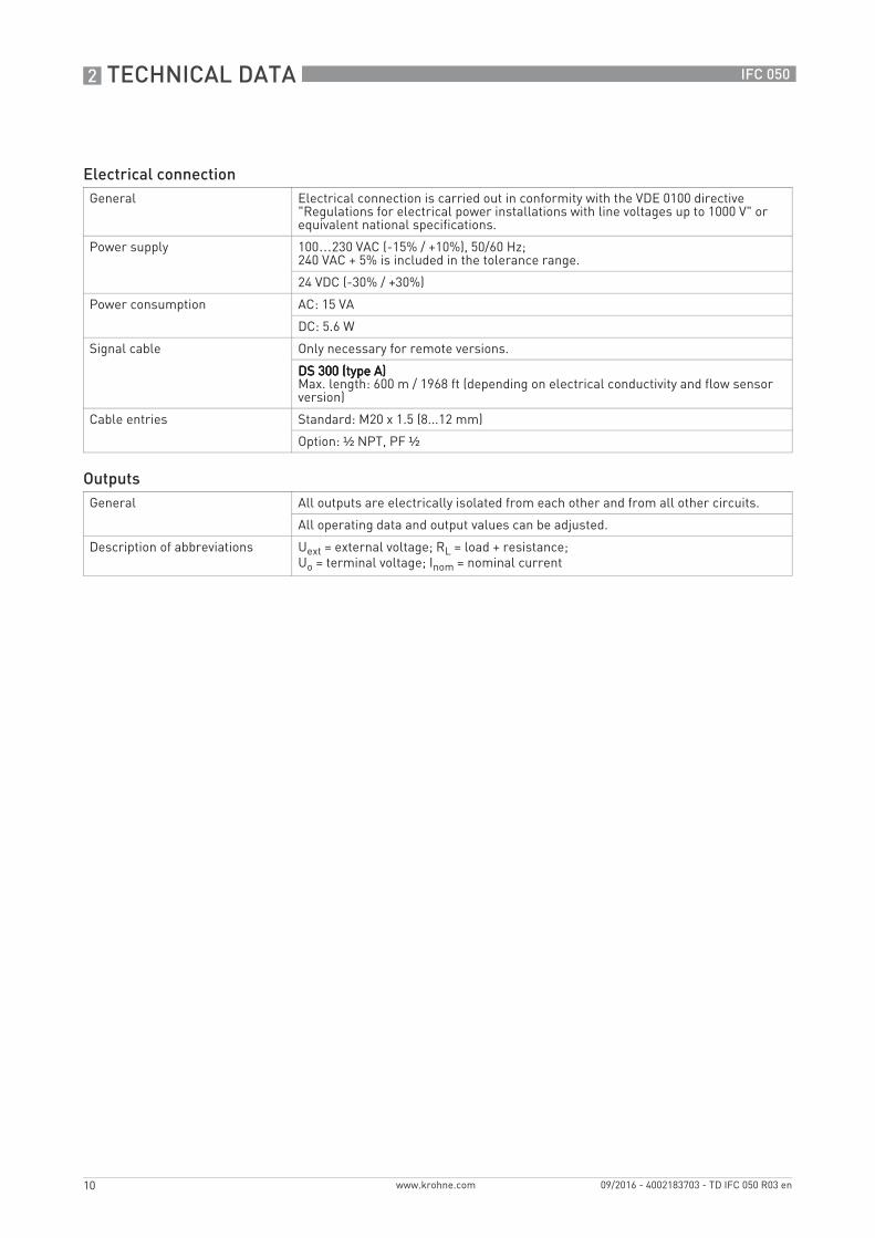
Low flow cut offLow flow cut offLow flow cut offLow flow cut off
Function Switching point and hysteresis separately adjustable for each output, counter and the display
Switching point Set in increments of 0.1%.
0…20% (current output, frequency output) or 0...±9.999 m/s (pulse output)
Hysteresis Set in increments of 0.1%.
0...5% (current output, frequency output) or 0...5 m/s (pulse output)
Time constantTime constantTime constantTime constant
Function The time constant corresponds to the elapsed time until 67% of the end value has been reached according to a step function.
Settings Set in increments of 0.1 seconds.
0…100 seconds
Status output / limit switchStatus output / limit switchStatus output / limit switchStatus output / limit switch
Function and settings Adjustable as automatic measuring range conversion, display of flow direction, counter overflow, error, switching point or empty pipe detection
Valve control with activated dosing function
Status and/or control: ON or OFF
Operating dataOperating dataOperating dataOperating data Basic I/Os + ModbusBasic I/Os + ModbusBasic I/Os + ModbusBasic I/Os + Modbus
Passive Independent of connection polarity.
Uext ≤ 32 VDC
I ≤ 100 mA
open:I ≤ 0.05 mA at Uext = 32 VDC
closed:U0 = 0.2 V at I ≤ 10 mAU0 = 2 V at I ≤ 100 mA
ModbusModbusModbusModbus
Description Modbus RTU, Master / Slave, RS485
Address range 1…247
Broadcast Supported with function code 16
Supported Baud rate 1200, 2400, 3600, 4800, 9600, 19200, 38400, 57600, 115200 Baud
Approvals and certificatesCE This device fulfils the statutory requirements of the relevant EU directives.
The manufacturer certifies successful testing of the product by applying the CE mark.
For full information of the EU directives & standards and the approved certifications, please refer to the EU declaration or the manufacturer website.
Other standards and approvalsOther standards and approvalsOther standards and approvalsOther standards and approvals
Shock and vibration resistance IEC 60068-2-3; EN 60068-2-6 and EN 60068-2-27; IEC 61298-3
NAMUR NE 21, NE 43, NE 53

2 TECHNICAL DATA
14
IFC 050
www.krohne.com 09/2016 - 4002183703 - TD IFC 050 R03 en
2.2 Dimensions and weight
2.2.1 Housing
Dimensions and weight in mm and kg
Dimensions and weight in inch and lb
Wall version
Dimensions [mm] Weight [kg]
a b c d e f g h k
Version with & without display
157 40 80 120 248 111.7 260 28.4 51.3 1.9
Dimensions [inch] Weight [lb]
a b c d e f g h k
Version with & without display
6.18 1.57 3.15 4.72 9.76 4.39 10.24 1.12 2.02 4.2

TECHNICAL DATA 2
15
IFC 050
www.krohne.com09/2016 - 4002183703 - TD IFC 050 R03 en
Dimensions and weight in mm and kg
Dimensions and weight in inch and lb
Compact version
Dimensions [mm] Weight [kg]
a b c d e f g
Version with & without display
157 40 80 148.2 101 260 95.5 1.8
Dimensions [inch] Weight [lb]
a b c d e f g
Version with & without display
6.18 1.57 3.15 5.83 3.98 10.24 3.76 4.0

2 TECHNICAL DATA
16
IFC 050
www.krohne.com 09/2016 - 4002183703 - TD IFC 050 R03 en
2.2.2 Mounting plate, wall version
Dimensions in mm and inch
[mm] [inch]
a Ø6.5 Ø0.26
b Ø8.1 Ø0.3
c 15 0.6
d 40 1.6
e 96 3.8
f 20 0.8
g 248 9.8
h 268 10.5
k 35 1.4
l 55 2.2
e
f
g h

TECHNICAL DATA 2
17
IFC 050
www.krohne.com09/2016 - 4002183703 - TD IFC 050 R03 en
2.3 Flow tables
Flow rate in m/s and m3/h
Q100 % in m3/h
v [m/s] 0.3 1 3 12
DN [mm] Minimum flow Nominal flow Maximum flow
2.5 0.005 0.02 0.05 0.21
4 0.01 0.05 0.14 0.54
6 0.03 0.10 0.31 1.22
10 0.08 0.28 0.85 3.39
15 0.19 0.64 1.91 7.63
20 0.34 1.13 3.39 13.57
25 0.53 1.77 5.30 21.21
32 0.87 2.90 8.69 34.74
40 1.36 4.52 13.57 54.29
50 2.12 7.07 21.21 84.82
65 3.58 11.95 35.84 143.35
80 5.43 18.10 54.29 217.15
100 8.48 28.27 84.82 339.29
125 13.25 44.18 132.54 530.15
150 19.09 63.62 190.85 763.40
200 33.93 113.10 339.30 1357.20
250 53.01 176.71 530.13 2120.52
300 76.34 254.47 763.41 3053.64
350 103.91 346.36 1039.08 4156.32
400 135.72 452.39 1357.17 5428.68
450 171.77 572.51 1717.65 6870.60
500 212.06 706.86 2120.58 8482.32
600 305.37 1017.90 3053.70 12214.80
700 415.62 1385.40 4156.20 16624.80
800 542.88 1809.60 5428.80 21715.20
900 687.06 2290.20 6870.60 27482.40
1000 848.22 2827.40 8482.20 33928.80
1200 1221.45 3421.20 12214.50 48858.00

2 TECHNICAL DATA
18
IFC 050
www.krohne.com 09/2016 - 4002183703 - TD IFC 050 R03 en
Flow rate in ft/s and US gallons/min
Q100 % in US gallons/min
v [ft/s] 1 3.3 10 40
DN [inch] Minimum flow Nominal flow Maximum flow
1/10 0.02 0.09 0.23 0.93
1/8 0.06 0.22 0.60 2.39
1/4 0.13 0.44 1.34 5.38
3/8 0.37 1.23 3.73 14.94
1/2 0.84 2.82 8.40 33.61
3/4 1.49 4.98 14.94 59.76
1 2.33 7.79 23.34 93.36
1.25 3.82 12.77 38.24 152.97
1.5 5.98 19.90 59.75 239.02
2 9.34 31.13 93.37 373.47
2.5 15.78 52.61 159.79 631.16
3 23.90 79.69 239.02 956.09
4 37.35 124.47 373.46 1493.84
5 58.35 194.48 583.24 2334.17
6 84.03 279.97 840.29 3361.17
8 149.39 497.92 1493.29 5975.57
10 233.41 777.96 2334.09 9336.37
12 336.12 1120.29 3361.19 13444.77
14 457.59 1525.15 4574.93 18299.73
16 597.54 1991.60 5975.44 23901.76
18 756.26 2520.61 7562.58 30250.34
20 933.86 3112.56 9336.63 37346.53
24 1344.50 4481.22 13445.04 53780.15
28 1829.92 6099.12 18299.20 73196.79
32 2390.23 7966.64 23902.29 95609.15
36 3025.03 10082.42 30250.34 121001.37
40 3734.50 12447.09 37346.00 149384.01
48 5377.88 17924.47 53778.83 215115.30

TECHNICAL DATA 2
19
IFC 050
www.krohne.com09/2016 - 4002183703 - TD IFC 050 R03 en
2.4 Measuring accuracy
Every electromagnetic flowmeter is calibrated by direct volume comparison. The wet calibration validates the performance of the flowmeter under reference conditions against accuracy limits.
The accuracy limits of electromagnetic flowmeters are typically the result of the combined effect of linearity, zero point stability and calibration uncertainty.
Reference conditions• Medium: water• Temperature: +5...+35°C / +41...+95°F• Operating pressure: 0.1...5 barg / 1.5...72.5 psig• Inlet section: ≥ 5 DN• Outlet section: ≥ 2 DN
X [m/s]: flow velocityY [%]: Accuracy of measured value (mv)
DN [mm] DN [inch] Standard accuracy 1 Optimised accuracy 2
OPTIFLUX 1050 10…150 3/8…6 ±0.5% of mv ± 1 mm/s ±0.25% of mv ± 1.5 mm/s
Extended calibration at 2 points
OPTIFLUX 2050 10…1200 3/8…48
OPTIFLUX 4050
OPTIFLUX 6050 10…150 3/8…6
WATERFLUX 3050 25...600 1...24 -

3 INSTALLATION
20
IFC 050
www.krohne.com 09/2016 - 4002183703 - TD IFC 050 R03 en
3.1 Intended use
The electromagnetic flowmeters are designed exclusively to measure the flow and conductivity of electrically conductive, liquid media.
3.2 Installation specifications
3.3 Mounting of the compact version
3.4 Mounting of the wall housing, remote version
1 Prepare the holes with the aid of the mounting plate.2 Fasten the device securely to the wall with the mounting plate.
If the device is not used according to the operating conditions (refer to chapter "Technical data"), the intended protection could be affected.
This device is a Group 1, Class A device as specified within CISPR11:2009. It is intended for use in industrial environment. There may be potential difficulties in ensuring electromagnetic compatibility in other environments, due to conducted as well as radiated disturbances.
The following precautions must be taken to ensure reliable installation.• Make sure that there is adequate space to the sides.• Protect the signal converter from direct sunlight and install a sun shade if necessary.• Signal converters installed in control cabinets require adequate cooling, e.g. by fan or heat
exchanger.• Do not expose the signal converter to intense vibrations. The measuring devices are tested
for a vibration level in accordance with IEC 68-2-64.
The signal converter is mounted directly on the flow sensor. For installation of the flowmeter, please observe the instructions in the supplied product documentation for the flow sensor.
Assembly materials and tools are not part of the delivery. Use the assembly materials and tools in compliance with the applicable occupational health and safety directives.
Figure 3-1: Mounting of the wall housing
INSTALLATION 3
21
IFC 050
www.krohne.com09/2016 - 4002183703 - TD IFC 050 R03 en
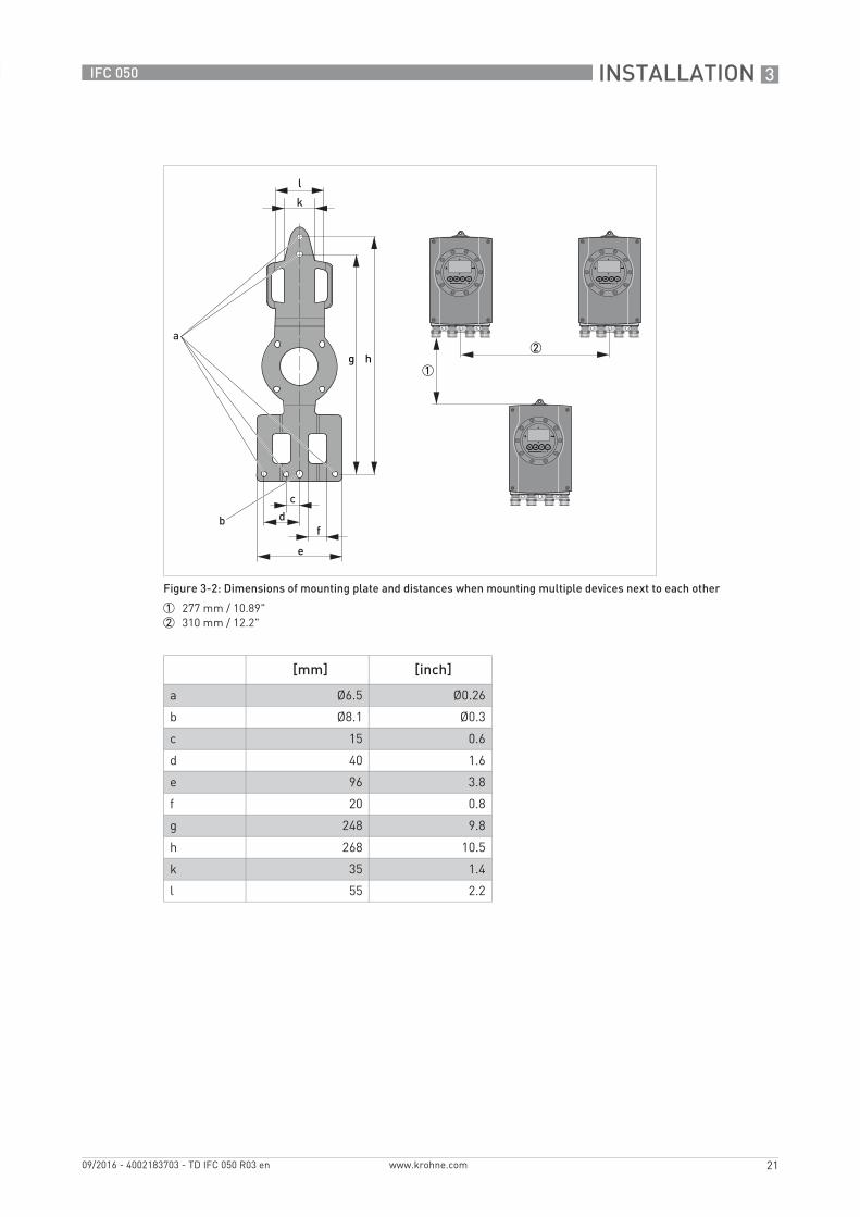
Figure 3-2: Dimensions of mounting plate and distances when mounting multiple devices next to each other
1 277 mm / 10.89"2 310 mm / 12.2"
[mm] [inch]
a Ø6.5 Ø0.26
b Ø8.1 Ø0.3
c 15 0.6
d 40 1.6
e 96 3.8
f 20 0.8
g 248 9.8
h 268 10.5
k 35 1.4
l 55 2.2
e
f
g h

4 ELECTRICAL CONNECTIONS
22
IFC 050
www.krohne.com 09/2016 - 4002183703 - TD IFC 050 R03 en
4.1 Safety instructions
4.2 Preparing the signal and field current cables
4.2.1 Signal cable A (type DS 300), construction
• Signal cable A is a double-shielded cable for signal transmission between the flow sensor and signal converter.
• Bending radius: ≥ 50 mm / 2"
All work on the electrical connections may only be carried out with the power disconnected. Take note of the voltage data on the nameplate!
Observe the national regulations for electrical installations!
Observe without fail the local occupational health and safety regulations. Any work done on the electrical components of the measuring device may only be carried out by properly trained specialists.
Look at the device nameplate to ensure that the device is delivered according to your order. Check for the correct supply voltage printed on the nameplate.
Assembly materials and tools are not part of the delivery. Use the assembly materials and tools in compliance with the applicable occupational health and safety directives.
Figure 4-1: Construction of signal cable A
1 Stranded drain wire (1) for the inner shield (10), 1.0 mm2 Cu / AWG 17 (not insulated, bare)
2 Insulated wire (2), 0.5 mm2 Cu / AWG 20
3 Insulated wire (3), 0.5 mm2 Cu / AWG 204 Outer sheath5 Insulation layers6 Stranded drain wire (6) for the outer shield (60)

ELECTRICAL CONNECTIONS 4
23
IFC 050
www.krohne.com09/2016 - 4002183703 - TD IFC 050 R03 en
4.2.2 Length of signal cable A
For temperatures of the medium above 150°C / 300°F, a special signal cable and a ZD intermediate socket are necessary. These are available including the changed electrical connection diagrams.
Flow sensor Nominal size Min. electrical conductivity[µS/cm]
Curve for signal cable A
DN [mm] [inch]
OPTIFLUX 1000 F 10...150 3/8...6 20 A1
OPTIFLUX 2000 F 25...150 1...6 20 A1
200...1200 8...48 20 A2
OPTIFLUX 4000 F 10...150 3/8...6 20 A1
200...1200 8...48 20 A2
OPTIFLUX 6000 F 10...150 3/8...6 20 A1
WATERFLUX 3000 F 25...600 1...24 20 A1
Figure 4-2: Maximum length of signal cable A
1 Maximum length of signal cable A between the flow sensor and signal converter [m]2 Maximum length of signal cable A between the flow sensor and signal converter [ft]3 Electrical conductivity of the medium being measured [μS/cm]

4 ELECTRICAL CONNECTIONS
24
IFC 050
www.krohne.com 09/2016 - 4002183703 - TD IFC 050 R03 en
4.2.3 Connection diagram for signal and field current cable
• A shielded 2-wire copper cable is used as the field current cable. The shielding MUSTMUSTMUSTMUST be connected in the housing of the flow sensor and signal converter.
• The outer shield (60) is connected in the terminal compartment of the flow sensor directly via the shield and a clip.
• Bending radius of signal and field current cable: ≥ 50 mm / 2"• The following illustration is schematic. The positions of the electrical connection terminals
may vary depending on the housing version.
The device must be grounded in accordance with regulations in order to protect personnel against electric shocks.
Figure 4-3: Connection diagram for signal and field current cable
1 Electrical terminal compartment in the signal converter2 Signal cable A3 Field current cable C4 Electrical terminal compartment in the flow sensor5 Functional ground FE

ELECTRICAL CONNECTIONS 4
25
IFC 050
www.krohne.com09/2016 - 4002183703 - TD IFC 050 R03 en
4.3 Grounding the flow sensor
• The flow sensor must be properly grounded.• The grounding cable should not transmit any interference voltages.• Do not use the grounding cable to connect any other electrical devices to ground at the same
time.• The flow sensors are connected to ground by means of a functional grounding conductor FE.• Special grounding instructions for the various flow sensors are provided in the separate
documentation for the flow sensor.• The documentation for the flow sensor also contain descriptions on how to use grounding
rings and how to install the flow sensor in metal or plastic pipes or in pipes which are coated on the inside.
4.4 Connecting the power supply
• The housings of the devices, which are designed to protect the electronic equipment from dust and moisture, should be kept well closed at all times. Creepage distances and clearances are dimensioned to VDE 0110 and IEC 664 for pollution severity 2. Supply circuits are designed for overvoltage category III and the output circuits for overvoltage category II.
• Fuse protection (IN ≤ 16 A) for the infeed power circuit, and also a separator (switch, circuit breaker) to isolate the signal converter must be provided.
There should be no difference in potential between the flow sensor and the housing or protective earth of the signal converter!
• To protect operators from electrical shock, during installation the cable for the power supply mustmustmustmust be run with sheathing insulation up to the mains cover. The insulated individual wires have to be only below the mains cover!
• If there is no mains cover or if it has been lost, the 100...230 VAC device may only be operated from the outside (with a magnet pencil) while closed!

4 ELECTRICAL CONNECTIONS
26
IFC 050
www.krohne.com 09/2016 - 4002183703 - TD IFC 050 R03 en
• To open the cover of the electrical terminal compartment, lightly press in the side walls of the mains cover 2.
• Flip the mains cover up.• Connect the power supply.• Close the mains cover again by flipping it down.
100...230 VAC (tolerance range: -15% / +10%)100...230 VAC (tolerance range: -15% / +10%)100...230 VAC (tolerance range: -15% / +10%)100...230 VAC (tolerance range: -15% / +10%)• Note the power supply voltage and frequency (50...60 Hz) on the nameplate.
24 VDC (tolerance range: -30% / +30%)24 VDC (tolerance range: -30% / +30%)24 VDC (tolerance range: -30% / +30%)24 VDC (tolerance range: -30% / +30%)• Note the data on the nameplate!• When connecting to functional extra-low voltages, provide a facility for protective separation
(PELV) (acc. to VDE 0100 / VDE 0106 and/or IEC 364 / IEC 536 or relevant national regulations).
Figure 4-4: Terminal compartment for power
1 Cable entry for power supply2 Mains cover3 Ground terminal4 100...230 VAC (-15% / +10%)5 24 VDC (-30% /+30%)
240 VAC + 5% is included in the tolerance range.

ELECTRICAL CONNECTIONS 4
27
IFC 050
www.krohne.com09/2016 - 4002183703 - TD IFC 050 R03 en
4.5 Inputs and outputs, overview
4.5.1 Description of the CG number
4.5.2 Fixed, non-alterable output versions
This signal converter is available with various output combinations.
• The grey boxes in the tables denote unassigned or unused connection terminals.• In the table, only the final digits of the CG no. are depicted.• Terminals D- and A- are connected for active pulse/frequency output (no galvanic isolation
anymore).• Available are an active or passive pulse/frequency output, or the active or passive status/limit
output. It's not possible to use both at the same time!
Basic outputs (I/Os)
Modbus (I/O) (option)
Description of used abbreviations
Figure 4-5: Marking (CG number) of the electronics module and output variants
1 ID number: 02 ID number: 0 = standard; 9 = special3 Power supply4 Display (language versions)5 Output version
CG no. Connection terminals
S D- D D+ A- A A+
1 0 0R 0 0
1 Pp / Sp passive Ip + HART® passive 2
connected to A-
Pa active connected to D-
Ia + HART® active 2
Pp / Sp passive Ia + HART® active 2
1 Shielding2 Function changed by reconnecting
CG no. Connection terminals
B- B B+ S
R 0 0 Sign. A (D0-) Common Sign. B (D1+) Shielding
Ia Ip Current output active or passive
Pa Pp Pulse/frequency output active or passive
Sa Sp Status output/limit switch active or passive

4 ELECTRICAL CONNECTIONS
28
IFC 050
www.krohne.com 09/2016 - 4002183703 - TD IFC 050 R03 en
4.6 Laying electrical cables correctly
1 For compact versions with nearly horizontally-oriented cable entries, lay the necessary elec-tric cables with a drip loop as shown in the illustration.
2 Tighten the screw connection of the cable entry securely.3 Seal cable entries that are not needed with a plug.
Figure 4-6: Protect housing from dust and water

NOTES 5
29
IFC 050
www.krohne.com09/2016 - 4002183703 - TD IFC 050 R03 en

5 NOTES
30
IFC 050
www.krohne.com 09/2016 - 4002183703 - TD IFC 050 R03 en

NOTES 5
31
IFC 050
www.krohne.com09/2016 - 4002183703 - TD IFC 050 R03 en

KROHNE – Process instrumentation and measurement solutions
• Flow
• Level
• Temperature
• Pressure
• Process Analysis
• Services
Head Office KROHNE Messtechnik GmbHLudwig-Krohne-Str. 547058 Duisburg (Germany)Tel.: +49 203 301 0Fax: +49 203 301 [email protected]
© K
RO
HN
E 09
/201
6 -
4002
1837
03 -
TD
IFC
050
R03
en
- Su
bjec
t to
chan
ge w
ithou
t not
ice.
The current list of all KROHNE contacts and addresses can be found at:www.krohne.com
KK
K