Embed Size (px)
Citation preview

1
M39075 ( IF-‐1) Integra-‐Fuse™ Rivet Tool
Marson is making installation easier than ever with the new Marson® Integra-Fuse™ (IF-1)
It’s the one-and-only tool needed for single-pull installations of open-end blind and structural rivets in all alloys from 3/16”- 1/4” *
Features: Capacity: up to ¼”* (6.350mm) Stroke length: 1.1250” (28.575mm) Pulling force: 4,600 lbs. (20.5kn) Air Consumption: 4CFM Dimensions: 12”X12.79”X4.99” Weight: 4.8lbs. (2.177 kg) * Does not include Huck® BOM® structural blind fasteners.
AFS Industrial Distribution Group 1925 N. MacArthur Drive Tracy, CA 95376 AFSIndustrial.com Customer Service: 800-‐826-‐2884 Tool Repair Dept: 800-‐826-‐2884 x 3032
2
WARNING: ALWAYS WEAR SAFETY GLASSES
WHEN OPERATING AND PERFORMING MAINTENANCE ON TOOL
AIR FEED Use only compressed air. Check airline for damage from humidity & contaminants. In order to protect the tool from premature wear, we recommend the use of air regulator and moisture filter
Recommended Air Pressure is 85 – 95 psi Air hose connection thread size is ¼” NPT.
WARNING: Do not use air supply greater than recommended or tool may be
damaged or burst.
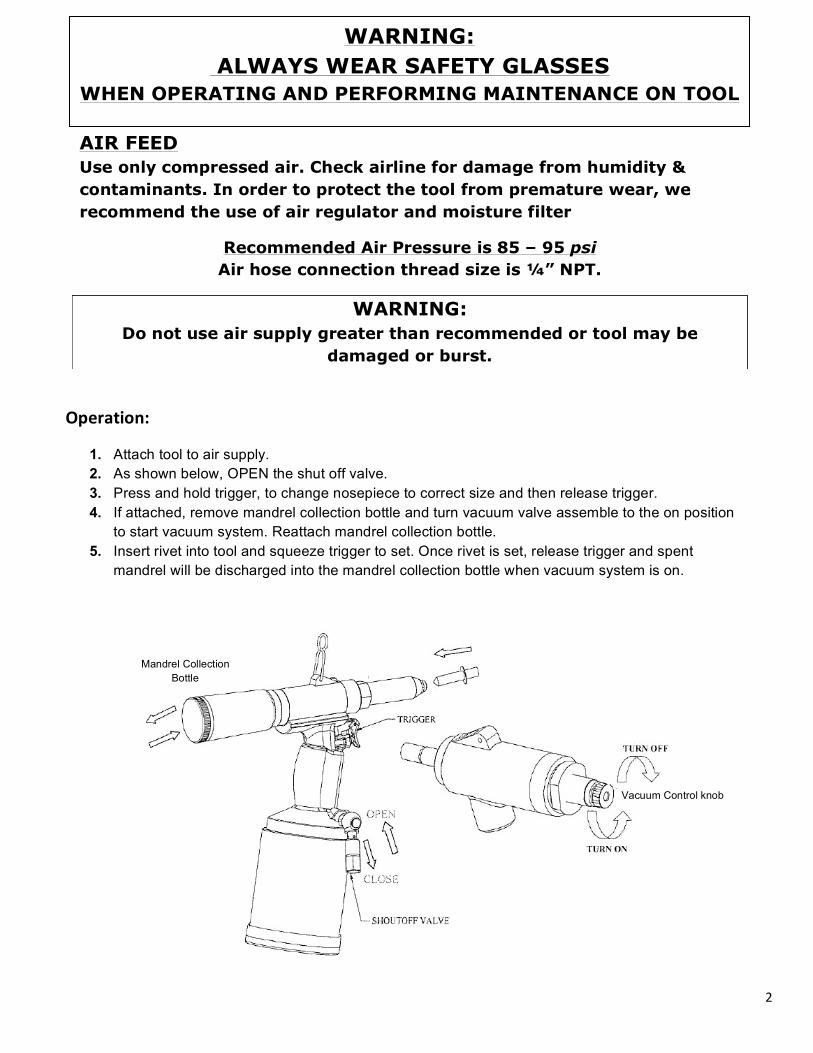
Operation:
1. Attach tool to air supply. 2. As shown below, OPEN the shut off valve. 3. Press and hold trigger, to change nosepiece to correct size and then release trigger. 4. If attached, remove mandrel collection bottle and turn vacuum valve assemble to the on position
to start vacuum system. Reattach mandrel collection bottle. 5. Insert rivet into tool and squeeze trigger to set. Once rivet is set, release trigger and spent
mandrel will be discharged into the mandrel collection bottle when vacuum system is on.
VVVVV
1
Vacuum Control knob
Mandrel Collection Bottle
2

3
How to change jaws
1. Remove the frame head (part #38, fig.1). 2. Using two wrenches, separate front jaw housing (part #39) from rear jaw housing (part #42, fig. 2). 3. Remove and replace part #40 (fig. 3 jaws) and re-assemble part #39 back onto tool (fig. 2). 4. Using spanner gauge (part #63), adjust position as shown in fig. 4 and tighten. 5. Reassemble frame head (part #38 fig.1) back onto tool and tighten together front jaw housing
(part #39) and rear jaw housing (part #42).
Fig. 1 Fig. 2
Fig. 3 Fig. 4
How to change the hydraulic oil
1. Remove the oil plug (#50) from the tool. 2. Hold tool upside down over a suitable container, apply air to the tool and squeeze the trigger 2-3
times to remove oil. 3. Release the air from the tool. 4. Fill the syringe that came in the tool kit with hydraulic oil. We recommend Mobil DTE 24 as our
preferred hydraulic oil. If recommended hydraulic fluid is not available be sure to use a non-foaming hydraulic fluid.
5. Screw the syringe into the top of the tool and press the top of the syringe until all of the oil has been inserted into the tool.
7. Repeat steps 5 & 6 until the tool no longer accepts oil. * * Note – the oil capacity should not exceed 14ml.
8. Remove the syringe and reinstall the oil plug. 9. Re-install the frame head back onto the tool.
Returning the tool to the factory setting
1. Loosen and remove the frame head (#38) from the tool. 2. Loosen the lock nut from the rear of the assembly. 3. Using the spanner gauge (see fig. 4 above), move the assembly until the distance of the front of
the collet case to the tool frame matches the distance on the spanner gauge. 4. Re-tighten the lock nut. 5. Re-install the frame head back onto tool.
4
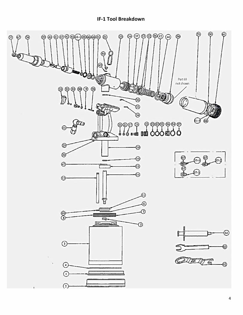
IF-‐1 Tool Breakdown
5
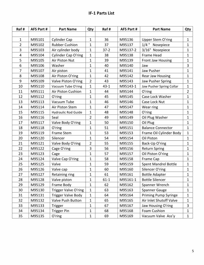
Ref # AFS Part # Part Name Qty Ref # AFS Part # Part Name Qty
1 M95101 Cylinder Cap 1 36 M95136 Upper Stem O'ring 1 2 M95102 Rubber Cushion 1 37 M95137 1/4 " Nosepiece 1 3 M95103 Air cylinder body 1 37-‐2 M95137-‐2 3/16" Nosepiece 1 4 M95104 Cylinder Cap O'ring 1 38 M95138 Frame Head 1 5 M95105 Air Piston Nut 1 39 M95139 Front Jaw Housing 1 6 M95106 Washer 1 40 M95140 Jaw 3 7 M95107 Air piston 1 41 M95141 Jaw Pusher 1 8 M95108 Air Piston O'ring 1 42 M95142 Rear Jaw Housing 1 9 M95109 Valve Piston O'ring 2 43 M95143 Jaw Pusher Spring 1 10 M95110 Vacuum Tube O'ring 1 43-‐1 M95143-‐1 Jaw Pusher Spring Collar 1 11 M95111 Air Piston Cushion 1 44 M95144 O'ring 2 12 M95112 O'ring 1 45 M95145 Case Lock Washer 1 13 M95113 Vacuum Tube 1 46 M95146 Case Lock Nut 1 14 M95114 Air Piston Stem 1 47 M95147 Wear ring 1 15 M95115 Hydraulic Rod Guide 1 48 M95148 O'ring 1 16 M95116 Seal 2 49 M95149 Oil Plug Washer 1 17 M95117 Valve Body O'ring 1 50 M95150 Oil Plug 1 18 M95118 O'ring 1 51 M95151 Balance Connector 1 19 M95119 Frame Stem 1 53 M95153 Frame Oil Cylinder Body 1 20 M95120 Silencer 1 54 M95154 Oil Piston 1 21 M95121 Valve Body O'ring 2 55 M95155 Back-‐Up O'ring 1 22 M95122 Cage O'ring 3 56 M95156 Return Spring 1 23 M95123 Cage 1 57 M95157 Oil Piston O'ring 1 24 M95124 Valve Cap O'ring 1 58 M95158 Frame Cap 1 25 M95125 Valve 1 59 M95159 Spent Mandrel Bottle 1 26 M95126 Valve cap 1 60 M95160 Silencer O'ring 1 27 M95127 Retaining ring 1 61 M95161 Bottle Adapter 1 28 M95128 Valve piston 1 61-‐1 M95161-‐1 Bottle Silencer 1 29 M95129 Frame Body 1 62 M95162 Spanner Wrench 1 30 M95130 Trigger Valve O'ring 1 63 M95163 Spanner Gauge 1 31 M95131 Trigger Valve Body 1 64 M95164 Priming Pump Syringe 1 32 M95132 Valve Push Button 1 65 M95165 Air Inlet Shutoff Valve 1 33 M95133 Trigger 1 67 M95167 Jaw Housing O'ring 3 34 M95134 Trigger Pin 1 68 M95168 Foam Cushion 1 35 M95135 O'ring 1 69 M95169 Vacuum Valve Ass’y 1
IF-‐1 Parts List
6
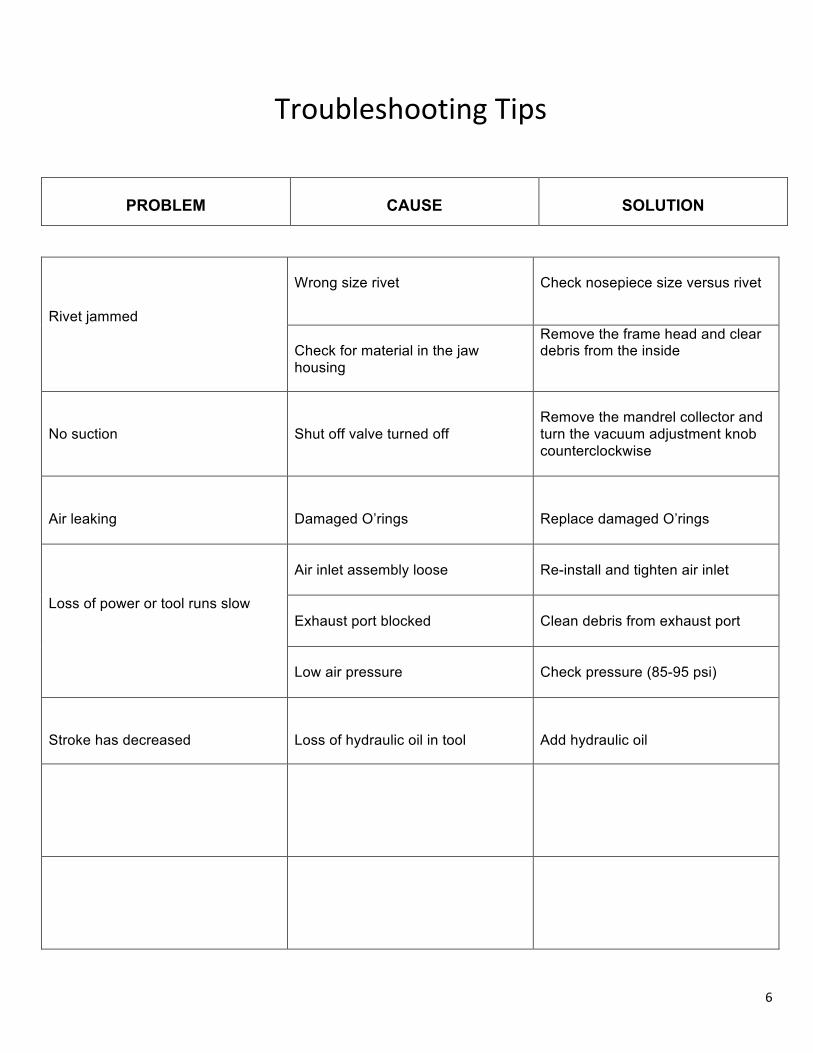
Troubleshooting Tips
PROBLEM
CAUSE
SOLUTION
Rivet jammed
Wrong size rivet
Check nosepiece size versus rivet
Check for material in the jaw housing
Remove the frame head and clear debris from the inside
No suction
Shut off valve turned off
Remove the mandrel collector and turn the vacuum adjustment knob counterclockwise
Air leaking
Damaged O’rings
Replace damaged O’rings
Loss of power or tool runs slow
Air inlet assembly loose
Re-install and tighten air inlet
Exhaust port blocked
Clean debris from exhaust port
Low air pressure
Check pressure (85-95 psi)
Stroke has decreased
Loss of hydraulic oil in tool
Add hydraulic oil
7
IMPORTANT WARRANTY INFORMATION Alcoa Fastening Systems (AFS), makers of Huck, Marson and Recoil brand fasteners, tools and accessories warrants that this tool will be free from defects in materials and workmanship under normal service and use for ninety (90) days from the date of purchase. This warranty applies to the purchaser of the tool for original use only. All other warranties, whether expressed or implied, including any warranties of merchantability or fitness for purpose are hereby excluded. Should this tool fail during this ninety (90) day period, and no unauthorized repairs have been made, return the tool freight prepaid to the factory free of charge for replacement of any part or parts found to be defective due to faulty material or workmanship. This represents the sole obligation under this warranty. In no event shall Alcoa Fastening Systems be liable for any consequential or special damages arising from the purchase or use of this tool. You may have other rights which may vary from state to state.
WARRANTY / OUT OF WARRANTY SHIPPING INSTRUCTIONS
WARRANTY REPAIR: Tools requiring warranty repair must be shipped to our tool repair facility with
a copy of the purchasers invoice and a tool warranty / repair form. Form can be downloaded at
http://afsindustrial.com/distribution/wp-content/uploads/TR_FORM_112713_Tracy.pdf or contact customer service to request a form at 800-826-2884
OUT OF WARRANTY: tools require only a completed warranty /repair form
Note: shipping address is located on the form