Embed Size (px)
Citation preview
2013 Moxa Inc. All rights reserved.
P/N: 1802004020020
IEX-402-VDSL2 Series Hardware Installation Guide
Moxa Managed VDSL2 Ethernet Extender
First Edition, Feb 2013
- 2 -
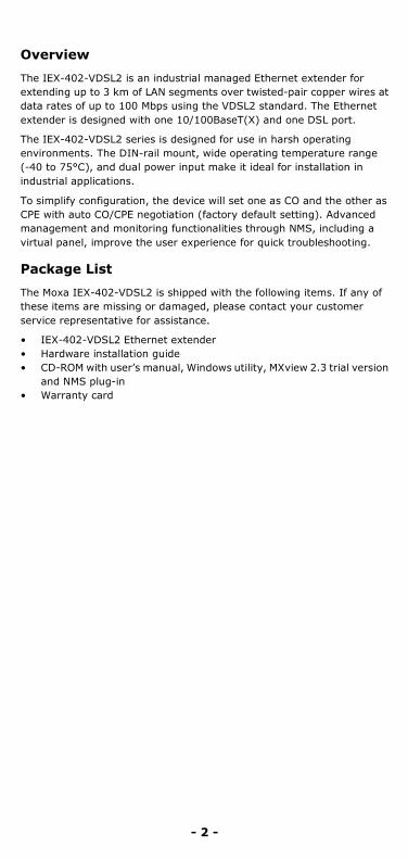
Overview
The IEX-402-VDSL2 is an industrial managed Ethernet extender for extending up to 3 km of LAN segments over twisted-pair copper wires at data rates of up to 100 Mbps using the VDSL2 standard. The Ethernet extender is designed with one 10/100BaseT(X) and one DSL port.
The IEX-402-VDSL2 series is designed for use in harsh operating environments. The DIN-rail mount, wide operating temperature range (-40 to 75°C), and dual power input make it ideal for installation in industrial applications.
To simplify configuration, the device will set one as CO and the other as CPE with auto CO/CPE negotiation (factory default setting). Advanced management and monitoring functionalities through NMS, including a virtual panel, improve the user experience for quick troubleshooting.
Package List
The Moxa IEX-402-VDSL2 is shipped with the following items. If any of these items are missing or damaged, please contact your customer service representative for assistance.
• IEX-402-VDSL2 Ethernet extender • Hardware installation guide • CD-ROM with user’s manual, Windows utility, MXview 2.3 trial version
and NMS plug-in • Warranty card

- 3 -
IEX-402-VDSL2 Panel Layout
Front Panel View
Top Panel View
Rear Panel View
1. Terminal block for power input (PWR1, PWR2)
2. Power input PWR1/PWR2 LED 3. State LED 4. Fault LED 5. 10/100BaseT(X) port 6. DSL speed/SNR LED 7. Detachable 2-contact DSL port 8. Link/ACT LED 9. TP port’s 10/100 Mbps LED
10. DSL port(RJ-45/RJ-11 connector) 11. CO/CPE LED 12. Model name 13. Grounding screw 14. Power input PWR1/PWR2 15. RS-232 console port 16. DIP switches 17. Reset button 18. Screw hole for wall mounting kit 19. DIN rail kit

- 4 -
Mounting Dimensions - unit = mm (inches)
DIN Rail Mounting
The aluminum DIN rail attachment plate should already be fixed to the back panel of the IEX-402-VDSL2 when you take it out of the box. If you need to reattach the DIN rail attachment plate, make sure the stiff metal spring is situated towards the top, as shown in the following figures.
STEP 1: Insert the top of the DIN rail into the slot just below the stiff metal spring.
STEP 2: The DIN rail attachment unit will snap into place as shown below.
To remove the Moxa Ethernet Extender from the DIN rail, simply reverse steps 1 and 2.
Wall Mounting (optional)
For some applications, you will find it convenient to mount the IEX-402-VDSL2 on the wall, as shown in the following figures.
STEP 1: Remove the aluminum DIN rail attachment plate from the IEX-402-VDSL2 rear panel, and then attach the wall mount plates as shown in the diagram as shown below.

- 5 -
STEP 2: Mounting the IEX-402-VDSL2 on the wall requires 4 screws. Use the switch, with wall mount plates attached, as a guide to mark the correct locations of the 4 screws. The heads of the screws should be less than 6.0 mm in diameter, and the shafts should be less than 3.5mm in diameter, as shown in the figure at the right.
NOTE Before tightening the screws into the wall, make sure the screw head and shank size are suitable by inserting the screw into one of the keyhole-shaped apertures of the wall mounting plates.
Do not tighten the screws completely—leave about 2 mm to allow room for sliding the wall mount panel between the wall and the screws.
STEP 3: Once the screws are fixed into the wall, insert the four screw heads through the large parts of the keyhole-shaped apertures, and then slide the IEX-402-VDSL2 downwards, as indicated. Tighten the four screws for added stability.
Wiring Requirement
ATTENTION
Safety First! Be sure to disconnect the power cord before installing and/or wiring your Moxa Ethernet Extender.
Calculate the maximum possible current in each power wire and common wire. Observe all electrical codes dictating the maximum current allowable for each wire size.
If the current goes above the maximum ratings, the wiring could overheat, causing serious damage to your equipment
Be sure to read and follow these important guidelines:
• Use separate paths to route wiring for power and devices. If power wiring and device wiring paths must cross, make sure the wires are perpendicular at the intersection point. NOTE: Do not run signal or communications wiring and power wiring through the same wire conduit. To avoid interference, wires with different signal characteristics should be routed separately.

- 6 -
• Use the type of signal transmitted through a wire to determine which wires should be kept separate. The rule of thumb is that wiring that shares similar electrical characteristics can be bundled together.
• Keep input wiring and output wiring separate. • When necessary, you should label the wiring to all devices in the
system.
Grounding the Ethernet Extender
Grounding and wire routing help limit the effects of noise due to electromagnetic interference (EMI). Run the ground connection from the ground screw to the grounding surface prior to connecting devices.
ATTENTION
This product is intended to be mounted onto a well-grounded mounting surface, such as a metal panel.
Wiring the Redundant Power Inputs
Both power inputs can be connected simultaneously to live DC power sources. If one power source fails, the other live source acts as a backup, and automatically supplies the IEX-402-VDSL2 with power.
The two 2-contact terminal block connectors on the IEX's top panel are used for IEX's two DC power inputs. Top and front view of the terminal block connectors are shown here.
Step 1: Insert the negative/positive DC wires into the V-/V+ terminals
Step 2: To keep the DC wires from pulling loose, use a small flat-blade screwdriver to tighten the wire-clamp screws on the front of the terminal block connector.
Step 3: Insert the plastic terminal block connector prongs into the terminal block receptor, which is located on IEX’s top panel.
ATTENTION
Before connecting the IEX-402-VDSL2 to the DC power inputs, make sure the DC power source voltage is stable.
Auto MDI/MDI-X Connection
The Auto MDI/MDI-X function allows users to connect the IEX-402-VDSL2’s 10/100BaseTX ports to any kind of Ethernet device, without needing to pay attention to the type of Ethernet cable being used for the connection. This means that you can use either a straight-through cable or cross-over cable to connect the IEX-402-VDSL2 to Ethernet devices.
Communication Connections
IEX-402-VDSL2 models have one 10/100BaseT(x) Ethernet port, and one DSL port.
- 7 -
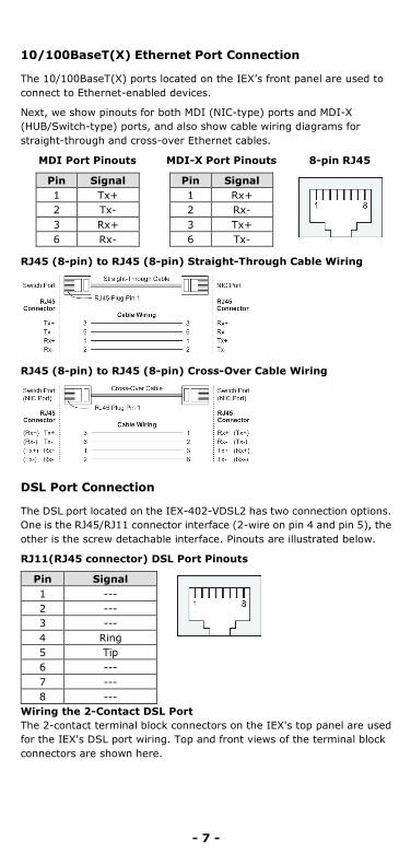
10/100BaseT(X) Ethernet Port Connection
The 10/100BaseT(X) ports located on the IEX’s front panel are used to connect to Ethernet-enabled devices.
Next, we show pinouts for both MDI (NIC-type) ports and MDI-X (HUB/Switch-type) ports, and also show cable wiring diagrams for straight-through and cross-over Ethernet cables.
MDI Port Pinouts MDI-X Port Pinouts 8-pin RJ45
Pin Signal 1 Tx+ 2 Tx- 3 Rx+ 6 Rx-
Pin Signal 1 Rx+ 2 Rx- 3 Tx+ 6 Tx-
RJ45 (8-pin) to RJ45 (8-pin) Straight-Through Cable Wiring
RJ45 (8-pin) to RJ45 (8-pin) Cross-Over Cable Wiring
DSL Port Connection
The DSL port located on the IEX-402-VDSL2 has two connection options. One is the RJ45/RJ11 connector interface (2-wire on pin 4 and pin 5), the other is the screw detachable interface. Pinouts are illustrated below.
RJ11(RJ45 connector) DSL Port Pinouts
Pin Signal 1 --- 2 --- 3 --- 4 Ring 5 Tip 6 --- 7 --- 8 ---
Wiring the 2-Contact DSL Port The 2-contact terminal block connectors on the IEX's top panel are used for the IEX's DSL port wiring. Top and front views of the terminal block connectors are shown here.

- 8 -
Step 1: Insert the wires into the Ring/Tip terminals
Step 2: To keep the wires from pulling loose, use a small flat-blade screwdriver to tighten the wire-clamp screws on the front of the terminal block connector.
Step 3: Insert the plastic terminal block connector prongs into the terminal block receptor, which is located on the IEX’s top panel.
RS-232 Console Port Connection
The IEX-402-VDSL2 has one RS-232 (10-pin RJ45) console port, located on the top panel. Use either an RJ45-to-DB9 (see the cable following wiring diagrams) to connect the IEX-402-VDSL2‘s console port to your PC’s COM port.
You may then use console terminal software, such as Moxa PComm Terminal Emulator, to access the IEX-402-VDSL2’S serial console.
RJ45 (10-pin) Console Port Pinouts
Pin Description 1 DCD 2 DSR 3 RTS 4 GND 5 TxD 6 RxD 7 GND 8 CTS 9 DTR 10 ---
RJ45 (10-pin) to DB9 (F) Cable Wiring
RJ45 (10-pin) to DB25 (F) Cable Wiring
Restore Factory Defaults Button
Press and hold the Reset button for 5 seconds to load the factory default settings. Use a pointed object, such as a straightened paper clip or toothpick, to depress the Reset button. This will cause the STATE LED to
- 9 -
blink once a second. After depressing the button for 5 continuous seconds, the STATE LED will start to blink rapidly. This indicates that factory default settings have been loaded and you can release the reset button.
NOTE Do NOT power off the Ethernet extender when loading default settings.
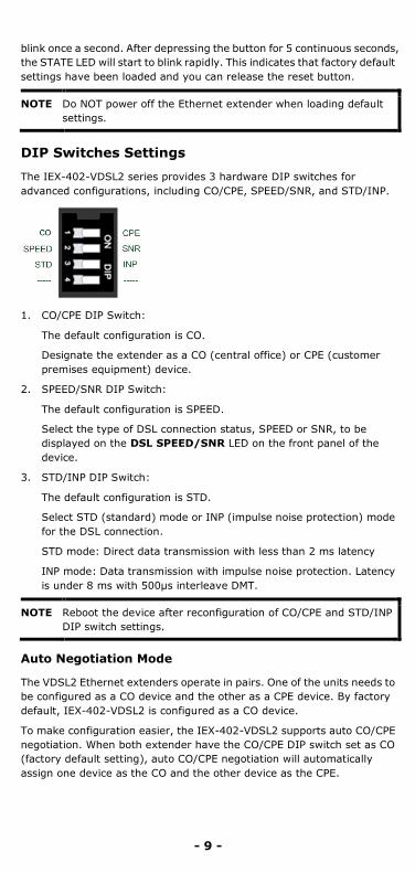
DIP Switches Settings
The IEX-402-VDSL2 series provides 3 hardware DIP switches for advanced configurations, including CO/CPE, SPEED/SNR, and STD/INP.
1. CO/CPE DIP Switch:
The default configuration is CO.
Designate the extender as a CO (central office) or CPE (customer premises equipment) device.
2. SPEED/SNR DIP Switch:
The default configuration is SPEED.
Select the type of DSL connection status, SPEED or SNR, to be displayed on the DSL SPEED/SNR LED on the front panel of the device.
3. STD/INP DIP Switch:
The default configuration is STD.
Select STD (standard) mode or INP (impulse noise protection) mode for the DSL connection.
STD mode: Direct data transmission with less than 2 ms latency
INP mode: Data transmission with impulse noise protection. Latency is under 8 ms with 500μs interleave DMT.
NOTE Reboot the device after reconfiguration of CO/CPE and STD/INP DIP switch settings.
Auto Negotiation Mode
The VDSL2 Ethernet extenders operate in pairs. One of the units needs to be configured as a CO device and the other as a CPE device. By factory default, IEX-402-VDSL2 is configured as a CO device.
To make configuration easier, the IEX-402-VDSL2 supports auto CO/CPE negotiation. When both extender have the CO/CPE DIP switch set as CO (factory default setting), auto CO/CPE negotiation will automatically assign one device as the CO and the other device as the CPE.
- 10 -
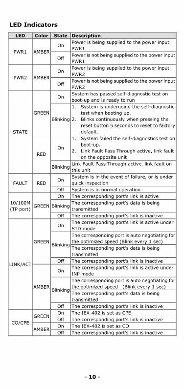
LED Indicators
LED Color State Description
PWR1 AMBER On
Power is being supplied to the power input PWR1
Off Power is not being supplied to the power input PWR1
PWR2 AMBER On
Power is being supplied to the power input PWR2
Off Power is not being supplied to the power input PWR2
STATE
GREEN
On System has passed self-diagnostic test on boot-up and is ready to run
Blinking
1. System is undergoing the self-diagnostic test when booting up.
2. Blinks continuously when pressing the reset button 5 seconds to reset to factory default.
RED On
1. System failed the self-diagnostics test on boot-up.
2. Link Fault Pass Through active, link fault on the opposite unit
Blinking Link Fault Pass Through active, link fault on this unit
FAULT RED On
System is in the event of failure, or is under quick inspection
Off System is in normal operation
10/100M (TP port)
GREEN
On The corresponding port’s link is active
Blinking The corresponding port’s data is being transmitted
Off The corresponding port’s link is inactive
LINK/ACT
GREEN
On The corresponding port’s link is active under STD mode
Blinking
The corresponding port is auto negotiating for the optimized speed (Blink every 1 sec) The corresponding port’s data is being transmitted
Off The corresponding port’s link is inactive
AMBER
On The corresponding port’s link is active under INP mode
Blinking
The corresponding port is auto negotiating for the optimized speed (Blink every 1 sec) The corresponding port’s data is being transmitted
Off The corresponding port’s link is inactive
CO/CPE GREEN
On The IEX-402 is set as CPE Off The corresponding port’s link is inactive
AMBER On The IEX-402 is set as CO Off The corresponding port’s link is inactive
- 11 -
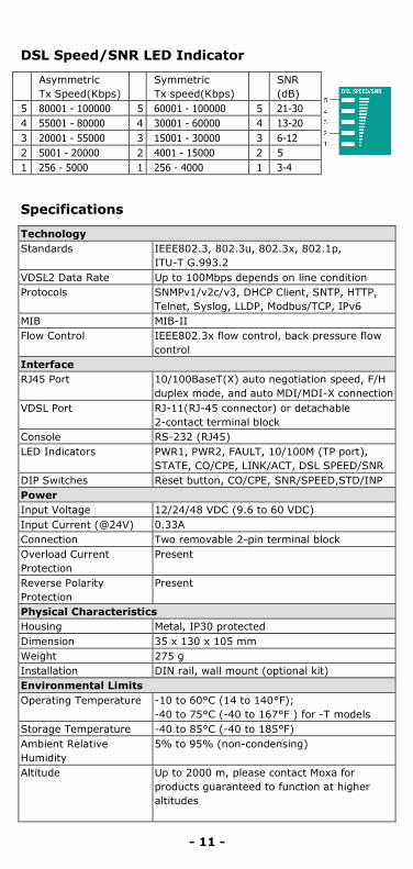
DSL Speed/SNR LED Indicator
Asymmetric Tx Speed(Kbps)
Symmetric Tx speed(Kbps)
SNR (dB)
5 80001 - 100000 5 60001 - 100000 5 21-30 4 55001 - 80000 4 30001 - 60000 4 13-20 3 20001 - 55000 3 15001 - 30000 3 6-12 2 5001 - 20000 2 4001 - 15000 2 5 1 256 - 5000 1 256 - 4000 1 3-4
Specifications
Technology Standards IEEE802.3, 802.3u, 802.3x, 802.1p,
ITU-T G.993.2 VDSL2 Data Rate Up to 100Mbps depends on line condition Protocols SNMPv1/v2c/v3, DHCP Client, SNTP, HTTP,
Telnet, Syslog, LLDP, Modbus/TCP, IPv6 MIB MIB-II Flow Control IEEE802.3x flow control, back pressure flow
control Interface RJ45 Port 10/100BaseT(X) auto negotiation speed, F/H
duplex mode, and auto MDI/MDI-X connection VDSL Port RJ-11(RJ-45 connector) or detachable
2-contact terminal block Console RS-232 (RJ45) LED Indicators PWR1, PWR2, FAULT, 10/100M (TP port),
STATE, CO/CPE, LINK/ACT, DSL SPEED/SNR DIP Switches Reset button, CO/CPE, SNR/SPEED,STD/INP Power Input Voltage 12/24/48 VDC (9.6 to 60 VDC) Input Current (@24V) 0.33A Connection Two removable 2-pin terminal block Overload Current Protection
Present
Reverse Polarity Protection
Present
Physical Characteristics Housing Metal, IP30 protected Dimension 35 x 130 x 105 mm Weight 275 g Installation DIN rail, wall mount (optional kit) Environmental Limits Operating Temperature -10 to 60°C (14 to 140°F);
-40 to 75°C (-40 to 167°F ) for -T models Storage Temperature -40 to 85°C (-40 to 185°F) Ambient Relative Humidity
5% to 95% (non-condensing)
Altitude Up to 2000 m, please contact Moxa for products guaranteed to function at higher altitudes

- 12 -
Regulatory Approvals Safety UL 508 EMI FCC Part 15 Subpart B Class A, CISPR
(EN55022) class A EMS EN61000-4-2 (ESD), Level 3
EN61000-4-3 (RS), Level 3 EN61000-4-4 (EFT), Level 3 EN61000-4-5 (Surge), Level 3 EN61000-4-6 (CS), Level 3 EN61000-4-8
Shock IEC60068-2-27 Freefall IEC60068-2-32 Vibration IEC60068-2-6 Warranty 5 years
ATTENTION
This device complies with Part 15 of the FCC rules. Operation is subject to the following conditions: 1. This device may not cause harmful interference. 2. This device must accept any interference received including interference that may cause undesired operation.
Technical Support Contact Information www.moxa.com/support
Moxa Americas: Toll-free: 1-888-669-2872 Tel: 1-714-528-6777 Fax: 1-714-528-6778
Moxa China (Shanghai office): Toll-free: 800-820-5036 Tel: +86-21-5258-9955 Fax: +86-21-5258-5505
Moxa Europe: Tel: +49-89-3 70 03 99-0 Fax: +49-89-3 70 03 99-99
Moxa Asia-Pacific: Tel: +886-2-8919-1230 Fax: +886-2-8919-1231


![Welcome [] · VDSL2 with weak FEXT VDSL2 with strong FEXT VDSL2, theoretical with Vectoring Dämpfung FEXT. Downstream [Mbps] – VDSL2 Profile 17a Reichweite Mit Vectoring kann fast](https://img.pdfslide.us/doc/110x75/5e1e042510f3b012214f201d/welcome-vdsl2-with-weak-fext-vdsl2-with-strong-fext-vdsl2-theoretical-with.jpg)