Embed Size (px)
DESCRIPTION
d
Citation preview
CCIE R&S Lab Workbook Volume I Version 5.0 BGP
Copyright © 2009 Internetwork Expert www.INE.comi
Copyright Information Copyright © 2009 Internetwork Expert, Inc. All rights reserved.
The following publication, CCIE R&S Lab Workbook Volume I Version 5.0, was developed by Internetwork Expert, Inc. All rights reserved. No part of this publication may be reproduced or distributed in any form or by any means without the prior written permission of Internetwork Expert, Inc.
Cisco®, Cisco® Systems, CCIE, and Cisco Certified Internetwork Expert, are registered trademarks of Cisco® Systems, Inc. and/or its affiliates in the U.S. and certain countries.
All other products and company names are the trademarks, registered trademarks, and service marks of the respective owners. Throughout this manual, Internetwork Expert, Inc. has used its best efforts to distinguish proprietary trademarks from descriptive names by following the capitalization styles used by the manufacturer.
CCIE R&S Lab Workbook Volume I Version 5.0 BGP
Copyright © 2009 Internetwork Expert www.INE.comii
Disclaimer
The following publication, CCIE R&S Lab Workbook Volume I Version 5.0, is designed to assist candidates in the preparation for Cisco Systems’ CCIE Routing & Switching Lab Exam. While every effort has been made to ensure that all material is as complete and accurate as possible, the enclosed material is presented on an “as is” basis. Neither the authors nor Internetwork Expert, Inc. assume any liability or responsibility to any person or entity with respect to loss or damages incurred from the information contained in this workbook.
This workbook was developed by Internetwork Expert, Inc. and is an original work of the aforementioned authors. Any similarities between material presented in this workbook and actual CCIE lab material is completely coincidental.
CCIE R&S Lab Workbook Volume I Version 5.0 BGP
Copyright © 2009 Internetwork Expert www.INE.comiii
Table of Contents BGP.................................................................................................... 1
7.1 Establishing iBGP Peerings.............................................................1 7.2 Establishing EBGP Peerings ...........................................................1 7.3 BGP Update Source Modification....................................................1 7.4 Multihop EBGP Peerings.................................................................1 7.5 Neighbor Disable-Connected-Check ...............................................2 7.6 Authenticating BGP Peerings ..........................................................2 7.7 iBGP Route Reflection.....................................................................2 7.8 Large Scale iBGP Route Reflection with Clusters ...........................3 7.9 iBGP Confederation.........................................................................4 7.10 BGP Next-Hop Processing - Next-Hop-Self ....................................5 7.11 BGP Next-Hop Processing - Manual Modification ...........................6 7.12 iBGP Synchronization......................................................................6 7.13 BGP over GRE ................................................................................6 7.14 BGP Redistribute Internal................................................................7 7.15 BGP Peer Groups............................................................................7 7.16 BGP Network Statement .................................................................7 7.17 BGP Auto-Summary ........................................................................7 7.18 BGP Bestpath Selection - Weight....................................................9 7.19 BGP Bestpath Selection - Local Preference....................................9 7.20 BGP Bestpath Selection - AS-Path Prepending ..............................9 7.21 BGP Bestpath Selection - Origin .....................................................9 7.23 BGP Bestpath Selection - MED.......................................................9 7.24 BGP Bestpath Selection - Always Compare MED...........................9 7.25 BGP Bestpath Selection - AS-Path Ignore ......................................9 7.26 BGP Bestpath Selection - Router-IDs............................................10 7.27 BGP Bestpath Selection - DMZ Link Bandwidth............................10 7.28 BGP Bestpath Selection - Maximum AS Limit ...............................10 7.29 BGP Backdoor...............................................................................10 7.30 BGP Aggregation ..........................................................................10 7.31 BGP Aggregation - Summary Only................................................10 7.32 BGP Aggregation - Suppress Map ................................................11 7.33 BGP Aggregation - Unsuppress Map ............................................11 7.34 BGP Aggregation - AS-Set ............................................................11 7.35 BGP Aggregation - Attribute-Map..................................................11 7.36 BGP Aggregation - Advertise Map.................................................11 7.37 BGP Communities .........................................................................12 7.38 BGP Communities - No-Advertise .................................................12 7.39 BGP Communities - No-Export......................................................12 7.40 BGP Communities - Local-AS .......................................................12 7.41 BGP Communities - Deleting.........................................................12 7.42 BGP Conditional Advertisement ....................................................13 7.43 BGP Conditional Route Injection ...................................................13
CCIE R&S Lab Workbook Volume I Version 5.0 BGP
Copyright © 2009 Internetwork Expert www.INE.comiv
7.44 BGP Filtering with Prefix-Lists .......................................................13 7.45 BGP Filtering with Standard Access-Lists .....................................13 7.46 BGP Filtering with Extended Access-Lists.....................................13 7.47 BGP Regular Expressions.............................................................14 7.48 BGP Filtering with Maximum Prefix ...............................................14 7.49 BGP Default Routing .....................................................................14 7.50 BGP Local AS ...............................................................................14 7.51 BGP Local AS Replace-AS/Dual-AS .............................................15 7.52 BGP Remove Private AS...............................................................15 7.53 BGP Dampening............................................................................15 7.54 BGP Dampening with Route-Map..................................................15 7.55 BGP Convergence Timers.............................................................16 7.56 BGP Fast Fall-over ........................................................................16 7.57 BGP Outbound Route Filtering......................................................16 7.58 BGP Soft Reconfiguration .............................................................16 7.59 BGP Next-Hop Trigger ..................................................................16 7.60 BGP TTL Security..........................................................................16 7.61 BGP AllowAS in.............................................................................17
BGP Solutions .................................................................................. 18 7.1 Establishing iBGP Peerings...........................................................18 7.2 Establishing EBGP Peerings .........................................................27 7.3 BGP Update Source Modification..................................................31 7.4 Multihop EBGP Peerings...............................................................36 7.5 Neighbor Disable-Connected-Check .............................................37 7.6 Authenticating BGP Peerings ........................................................42 7.7 iBGP Route Reflection...................................................................43 7.8 Large Scale iBGP Route Reflection with Clusters .........................49 7.9 iBGP Confederation.......................................................................61 7.10 BGP Next-Hop Processing - Next-Hop-Self ..................................67 7.11 BGP Next-Hop Processing - Manual Modification .........................73 7.12 iBGP Synchronization....................................................................76 7.13 BGP over GRE ..............................................................................83 7.14 BGP Redistribute Internal..............................................................87 7.15 BGP Peer Groups..........................................................................92 7.16 BGP Network Statement ...............................................................97 7.17 BGP Auto-Summary ....................................................................101 7.18 BGP Bestpath Selection - Weight................................................106 7.19 BGP Bestpath Selection - Local Preference................................111 7.20 BGP Bestpath Selection - AS-Path Prepending ..........................114 7.21 BGP Bestpath Selection - Origin .................................................118 7.22 BGP Bestpath Selection - MED...................................................121 7.24 BGP Bestpath Selection - Always Compare MED.......................126 7.25 BGP Bestpath Selection - AS-Path Ignore ..................................131 7.26 BGP Bestpath Selection - Router-IDs..........................................135 7.27 BGP Bestpath Selection - DMZ Link Bandwidth..........................138
CCIE R&S Lab Workbook Volume I Version 5.0 BGP
Copyright © 2009 Internetwork Expert www.INE.comv
7.28 BGP Bestpath Selection - Maximum AS Limit .............................142 7.29 BGP Backdoor.............................................................................145 7.30 BGP Aggregation ........................................................................148 7.31 BGP Aggregation - Summary Only..............................................152 7.32 BGP Aggregation - Suppress Map ..............................................154 7.33 BGP Aggregation - Unsuppress Map ..........................................157 7.34 BGP Aggregation - AS-Set ..........................................................161 7.35 BGP Aggregation - Attribute-Map................................................164 7.36 BGP Aggregation - Advertise Map...............................................168 7.37 BGP Communities .......................................................................171 7.38 BGP Communities - No-Advertise ...............................................177 7.39 BGP Communities - No-Export....................................................179 7.40 BGP Communities - Local-AS .....................................................182 7.41 BGP Communities - Deleting.......................................................185 7.42 BGP Conditional Advertisement ..................................................188 7.43 BGP Conditional Route Injection .................................................193 7.44 BGP Filtering with Prefix-Lists .....................................................198 7.45 BGP Filtering with Standard Access-Lists ...................................202 7.46 BGP Filtering with Extended Access-Lists...................................205 7.47 BGP Regular Expressions...........................................................208 7.48 BGP Filtering with Maximum Prefix .............................................214 7.49 BGP Default Routing ...................................................................216 7.50 BGP Local AS .............................................................................218 7.51 BGP Local AS Replace-AS/Dual-AS ...........................................223 7.52 BGP Remove Private AS.............................................................228 7.53 BGP Dampening..........................................................................232 7.54 BGP Dampening with Route-Map................................................236 7.55 BGP Timers Tuning .....................................................................239 7.56 BGP Fast Fallover .......................................................................242 7.57 BGP Outbound Route Filtering....................................................245 7.58 BGP Soft Reconfiguration ...........................................................248 7.59 BGP Next-Hop Trigger ................................................................251 7.60 BGP TTL Security........................................................................253 7.61 BGP AllowAS in...........................................................................255
CCIE R&S Lab Workbook Volume I Version 5.0 BGP
Copyright © 2009 Internetwork Expert www.INE.com1
BGP
Note
Load the Initial BGP initial configurations prior to starting.
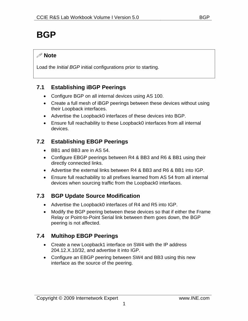
7.1 Establishing iBGP Peerings • Configure BGP on all internal devices using AS 100. • Create a full mesh of iBGP peerings between these devices without using
their Loopback interfaces. • Advertise the Loopback0 interfaces of these devices into BGP. • Ensure full reachability to these Loopback0 interfaces from all internal
devices.
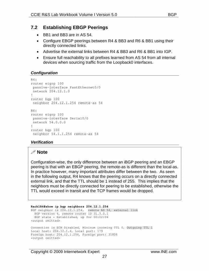
7.2 Establishing EBGP Peerings • BB1 and BB3 are in AS 54. • Configure EBGP peerings between R4 & BB3 and R6 & BB1 using their
directly connected links. • Advertise the external links between R4 & BB3 and R6 & BB1 into IGP. • Ensure full reachability to all prefixes learned from AS 54 from all internal
devices when sourcing traffic from the Loopback0 interfaces.
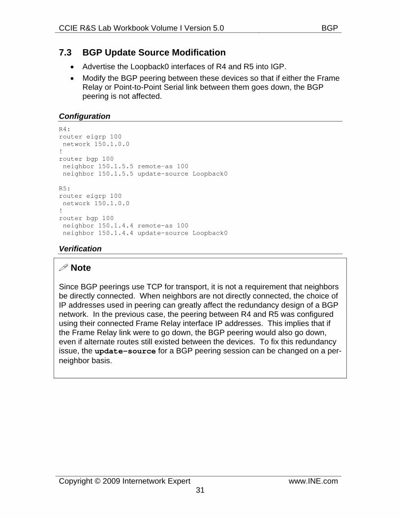
7.3 BGP Update Source Modification • Advertise the Loopback0 interfaces of R4 and R5 into IGP. • Modify the BGP peering between these devices so that if either the Frame
Relay or Point-to-Point Serial link between them goes down, the BGP peering is not affected.
7.4 Multihop EBGP Peerings • Create a new Loopback1 interface on SW4 with the IP address
204.12.X.10/32, and advertise it into IGP. • Configure an EBGP peering between SW4 and BB3 using this new
interface as the source of the peering.
CCIE R&S Lab Workbook Volume I Version 5.0 BGP
Copyright © 2009 Internetwork Expert www.INE.com2
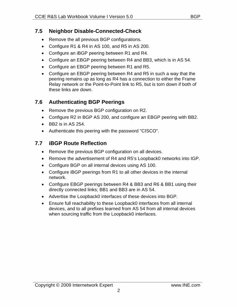
7.5 Neighbor Disable-Connected-Check • Remove the all previous BGP configurations. • Configure R1 & R4 in AS 100, and R5 in AS 200. • Configure an iBGP peering between R1 and R4. • Configure an EBGP peering between R4 and BB3, which is in AS 54. • Configure an EBGP peering between R1 and R5. • Configure an EBGP peering between R4 and R5 in such a way that the
peering remains up as long as R4 has a connection to either the Frame Relay network or the Point-to-Point link to R5, but is torn down if both of these links are down.
7.6 Authenticating BGP Peerings • Remove the previous BGP configuration on R2. • Configure R2 in BGP AS 200, and configure an EBGP peering with BB2. • BB2 is in AS 254. • Authenticate this peering with the password "CISCO".
7.7 iBGP Route Reflection • Remove the previous BGP configuration on all devices. • Remove the advertisement of R4 and R5’s Loopback0 networks into IGP. • Configure BGP on all internal devices using AS 100. • Configure iBGP peerings from R1 to all other devices in the internal
network. • Configure EBGP peerings between R4 & BB3 and R6 & BB1 using their
directly connected links; BB1 and BB3 are in AS 54. • Advertise the Loopback0 interfaces of these devices into BGP. • Ensure full reachability to these Loopback0 interfaces from all internal
devices, and to all prefixes learned from AS 54 from all internal devices when sourcing traffic from the Loopback0 interfaces.
CCIE R&S Lab Workbook Volume I Version 5.0 BGP
Copyright © 2009 Internetwork Expert www.INE.com3
7.8 Large Scale iBGP Route Reflection with Clusters • Remove the previous BGP configuration on all devices. • Configure R2 in BGP AS 200, and configure an EBGP peering with BB2. • BB2 is in AS 254, and is authenticating this peering with the password
"CISCO". • Configure BGP on all other internal devices using AS 100. • Configure a BGP cluster between R1, R4, and R6 as follows:
o R1 should be the route-reflector, and peer with R4 and R6. o R4 and R6 should peer with BB3 and BB1 respectively, who are in
AS 54. o Use the cluster-id 150.X.1.1.
• Configure a BGP cluster between R3, SW1, and SW3 as follows: o R3 should be the route-reflector, and peer with SW1 and SW3. o Use the cluster-id 150.X.3.3.
• Configure a BGP cluster between R5, SW2, and SW4 as follows: o R5 should be the route-reflector, and peer with SW2 and SW4. o Use the cluster-id 150.X.5.5.
• R1, R3, and R5 should all peer with each other in a full-mesh, but should not propagate updates between clusters.
• Configure EBGP peerings between R2 & R3 and R2 & R5. • Advertise the Loopback0 interfaces of all devices into BGP. • Ensure full reachability to these Loopback0 interfaces from all internal
devices, and to all prefixes learned from AS 54 and 254 from all internal devices when sourcing traffic from the Loopback0 interfaces.
CCIE R&S Lab Workbook Volume I Version 5.0 BGP
Copyright © 2009 Internetwork Expert www.INE.com4
7.9 iBGP Confederation • Remove the BGP configuration of all devices in AS 100. • Configure a BGP Confederation Sub-AS between R1, R4, and R6 as
follows: o Use the Sub-AS number 65146. o Use the Public AS number 100. o Configure full-mesh peerings between R1, R4, and R6. o R4 and R6 should peer with BB3 and BB1 respectively.
• Configure a BGP Confederation Sub-AS between R3, SW1, and SW3 as follows:
o Use the Sub-AS number 65379. o Use the Public AS number 100. o Configure full-mesh peerings between R3, SW1, and SW3.
• Configure a BGP Confederation Sub-AS between R5, SW2, and SW4 as follows:
o Use the Sub-AS number 65508. o Use the Public AS number 100. o R5 should be a route-reflector, and peer with SW2 and SW4.
• R1, R3, and R5 should all peer with each other in a full-mesh. • Configure EBGP peerings between R2 & R3 and R2 & R5. • Advertise the Loopback0 interfaces of all devices into BGP. • Ensure full reachability to these Loopback0 interfaces from all internal
devices, and to all prefixes learned from AS 54 and 254 from all internal devices when sourcing traffic from the Loopback0 interfaces.
CCIE R&S Lab Workbook Volume I Version 5.0 BGP
Copyright © 2009 Internetwork Expert www.INE.com5
7.10 BGP Next-Hop Processing - Next-Hop-Self • Remove the previous BGP configuration on all devices. • Configure R2 in BGP AS 200, and configure an EBGP peering with BB2. • BB2 is in AS 254, and is authenticating this peering with the password
"CISCO". • Configure BGP on all other internal devices using AS 100. • Configure iBGP peerings from R1 to all other devices in AS 100. • Configure EBGP peerings between R4 & BB3 and R6 & BB1 using their
directly connected links; BB1 and BB3 are in AS 54. • Configure EBGP peerings between R2 & R3 and R2 & R5. • Advertise the Loopback0 interfaces of all devices into BGP. • Remove the advertisement of the links between R4 & BB3 and R6 & BB1
into IGP. • Use the next-hop-self command where necessary to ensure full
connectivity to the prefixes coming from AS 54. • Ensure full reachability to the Loopback0 interfaces from all internal
devices, and to all prefixes learned from AS 54 and AS 254 from all internal devices when sourcing traffic from the Loopback0 interfaces.
CCIE R&S Lab Workbook Volume I Version 5.0 BGP
Copyright © 2009 Internetwork Expert www.INE.com6
7.11 BGP Next-Hop Processing - Manual Modification • Remove the previously configured next-hop-self statements. • Configure an outbound route-map on R4, and an inbound route-map on
R1 in order to resolve any next-hop reachability issues for the routes learned from AS 54.
7.12 iBGP Synchronization • Remove all BGP the configuration on the devices in AS 100. • Configure BGP on all internal devices, with the exception of R2, using AS
100. • Configure iBGP peerings from R1 to all other devices in AS 100. • Configure EBGP peerings between R4 & BB3 and R6 & BB1 using their
directly connected links; BB1 and BB3 are in AS 54. • Configure EBGP peerings between R2 & R3 and R2 & R5. • Advertise the Loopback0 interfaces of all devices into BGP. • Disable iBGP Synchronization on all devices in AS 100. • Ensure full reachability to the Loopback0 interfaces from all internal
devices, and to all prefixes learned from AS 54 and AS 254 from all internal devices when sourcing traffic from the Loopback0 interfaces.
Note
Revert all devices to the Initial BGP initial configurations prior to continuing.
7.13 BGP over GRE • Configure R4 in AS 100, with an EBGP peering to BB3 in AS 54. • Configure R2 in AS 200, with an EBGP peering to BB2 in AS 254 using
the password CISCO. • Configure an EBGP peering between R2 and R4. • Advertise the Loopback0 networks of R2 and R4 into BGP. • Ensure that R2 can reach prefixes learned from AS 54, and R4 can reach
prefixes learned from AS 254 when sourcing traffic from their Loopback0 networks.
• Do not redistribute between BGP and IGP to accomplish this.
CCIE R&S Lab Workbook Volume I Version 5.0 BGP
Copyright © 2009 Internetwork Expert www.INE.com7
7.14 BGP Redistribute Internal • Remove the BGP configuration on all devices. • Configure R1, R3, R4, and R6 in AS 100. • R4 and R6 should peer with BB3 and BB1 respectively, who are in AS 54. • R1 should peer with R3, R4, and R6 as a route reflector. • Configure R4 and R6 to advertise the network 155.X.0.0/16 to AS 54. • Configure BGP to IGP redistribution on R3 so that all internal devices
have reachability to the prefixes learned from AS 54.
7.15 BGP Peer Groups • Remove all BGP the configuration on the devices in AS 100. • Configure BGP on all internal devices, with the exception of R2 and all
switches, using AS 100. • Configure iBGP peerings from R1 to all other devices in AS 100 using the
peer group named IBGP_PEERS. • Configure EBGP peerings between R4 & BB3 and R6 & BB1 using their
directly connected links; BB1 and BB3 are in AS 54. • Advertise the Loopback0 interfaces of all devices into BGP. • Ensure full reachability to the Loopback0 interfaces from all internal
devices, and to all prefixes learned from AS 54 • Do not advertise the links connected to BB1 and BB3 into IGP or BGP
7.16 BGP Network Statement • Remove the next-hop-self statement used in the previous task to peer
with BB1 and BB3 • Ensure full reachability from your internal network to all routes learned
from AS 54 but do not advertise any prefixes into IGP
7.17 BGP Auto-Summary • Configure R4 and R6 to originate classfull auto-summaries for all of your
internally assigned address space. • BB1 and BB3 should not see any of the subnet advertisements that make
up this summary. • Ensure full reachability from your internal network to all routes learned
from AS 54. • Do not use the aggregate-address command to accomplish this.
CCIE R&S Lab Workbook Volume I Version 5.0 BGP
Copyright © 2009 Internetwork Expert www.INE.com8
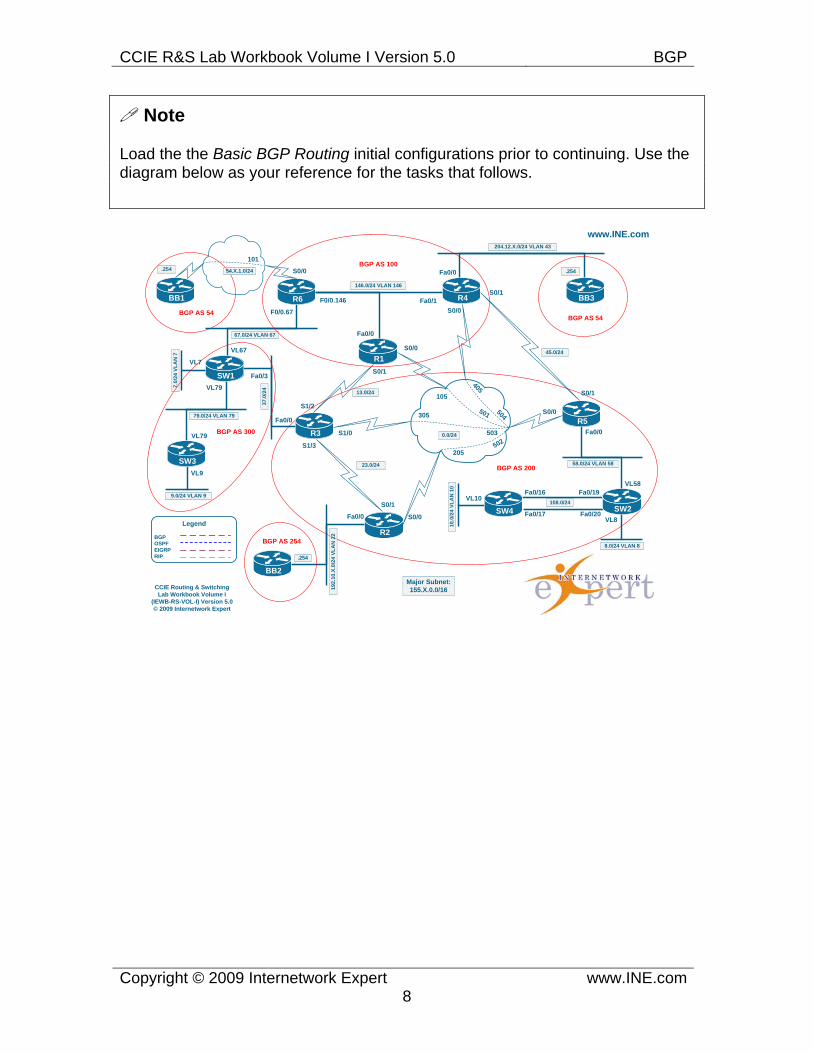
Note
Load the the Basic BGP Routing initial configurations prior to continuing. Use the diagram below as your reference for the tasks that follows.
VL9
9.0/24 VLAN 9 VL10
www.INE.com
.254 S0/0
F0/0.67
146.0/24 VLAN 146
F0/0.146
67.0/24 VLAN 67
37.0
/24
204.12.X.0/24 VLAN 43
192.
10.X
.0/2
4 VL
AN
22
58.0/24 VLAN 58
45.0/24
23.0/24
13.0/24
504501
503
502205
305
105
405
0.0/24
7.0/
24 V
LAN
7
.254
Fa0/1
Fa0/0
Fa0/0
S0/0
S0/1
S1/0
S1/3
S1/2
S0/1
S0/0Fa0/0
.254
Fa0/0
Fa0/3
VL67
VL7
Fa0/0
S0/0
S0/1
VL58
VL8
8.0/24 VLAN 8
S0/0
S0/1
54.X.1.0/24
101
Fa0/19
Fa0/20
Fa0/16
Fa0/17
108.0/24
10.0
/24
VLA
N 1
0
79.0/24 VLAN 79
VL79
VL79
CCIE Routing & Switching Lab Workbook Volume I
(IEWB-RS-VOL-I) Version 5.0© 2009 Internetwork Expert
R6
R1
R4 BB3
SW1
R3
R2
R5
SW4 SW2
BB2
SW3
BB1
R1
Legend
BGPOSPF EIGRP RIP
Major Subnet: 155.X.0.0/16
BGP AS 100
BGP AS 200
BGP AS 254
BGP AS 300
BGP AS 54BGP AS 54
CCIE R&S Lab Workbook Volume I Version 5.0 BGP
Copyright © 2009 Internetwork Expert www.INE.com9
7.18 BGP Bestpath Selection - Weight • Using the most influential attribute, configure SW1 so that traffic from AS
300 going to AS 54 prefixes exits towards R3, and that traffic from AS 300 going to AS 254 networks exits towards R6.
7.19 BGP Bestpath Selection - Local Preference • Remove the BGP configuration for the previous task from SW1. • Use the local-preference in R6 so that traffic from AS 100 going to AS 254
transits through AS 300.
7.20 BGP Bestpath Selection - AS-Path Prepending • Remove the BGP configuration for the previous task from R6. • Using AS-Path Prepending, configure AS 200 so that traffic from AS 100
going to AS 254 enters via the link to AS 300.
7.21 BGP Bestpath Selection - Origin • Remove the BGP configuration made for the previous task. • Using Origin attribute configure AS 200 so that traffic from AS 100 going
to AS 254 enters via the link between R4 and R5.
7.23 BGP Bestpath Selection - MED • Remove the BGP configuration made for the previous task. • Using MED configure AS 100 so that traffic from AS 200 going to AS 54
enters via the link between R4 and R5.
7.24 BGP Bestpath Selection - Always Compare MED • Remove the BGP configuration made for the previous task. • Create a new Loopback1 interface on both R6 and SW3 with the IP
address 1.2.3.4/32 and advertise it into BGP on both R6 and SW3. • Using just the MED attribute configure the network so that traffic from AS
200 going to this prefix is always received by SW3.
7.25 BGP Bestpath Selection - AS-Path Ignore • Remove the BGP configuration made for the previous task. • Ensure that traffic from AS 200 to AS 54 prefixes takes path across AS
300. • Do not use AS-PATH prepending to accomplish this.
CCIE R&S Lab Workbook Volume I Version 5.0 BGP
Copyright © 2009 Internetwork Expert www.INE.com10
7.26 BGP Bestpath Selection - Router-IDs • Modify the BGP router-ids in AS 100 as necessary so that traffic from R1
to AS 54 exits via R6.
7.27 BGP Bestpath Selection - DMZ Link Bandwidth • Modify the configuration of AS 100 routers so that R1 load-balances to the
paths in AS 54 proportional to the bandwidth of the links connecting R4 and R6 to AS 54 routers.
• The bandwidth of the link connectiong R6 to BB1 equals to 2Mbps.
7.28 BGP Bestpath Selection - Maximum AS Limit • Remove the BGP configuration made for the previous task. • Configure the routers in AS 100 to accept only the prefixes originated from
directly connected ASes. • Do not use filtering based on AP-PATH access-lists to accomplish this.
7.29 BGP Backdoor • Remove the BGP configuration applied in the previous task. • Shutdown the BGP peering link between AS 100 and AS 300 • Create a new Loopback1 interface in SW1 with the IP address
150.1.77.77/24 and advertise it into BGP. • Configure R1 and R4 so that they prefer reaching the new subnet via
EIGRP as opposed to eBGP.
7.30 BGP Aggregation • Remove the BGP configuration made for the previous task. • Configure R2 with four new Loopback interfaces with the IP addresses
10.0.0.1/24, 10.0.1.1/24, 10.0.2.1/24, and 10.0.3.1/24. • Advertise an aggregate route for these networks that does not overlap any
address space.
7.31 BGP Aggregation - Summary Only • Modify the configuration for the previous task so that no other devices but
R2 could see the specific prefixes that make up the summary.
CCIE R&S Lab Workbook Volume I Version 5.0 BGP
Copyright © 2009 Internetwork Expert www.INE.com11
7.32 BGP Aggregation - Suppress Map • Modify the solution for the previous task so that R2 advertises 10.0.2.0/24
prefix in addition to the summary route.
7.33 BGP Aggregation - Unsuppress Map • Remove the summarization configured in R2. • Using the summary-only feature, configure R3 and R5 to originate an
aggregate route for these networks that does not overlap any address space.
• Using the unsuppress-map feature configure the network in such a way that traffic from AS 100 and 54 going to the prefix 10.0.1.0/24 always transits AS 300 unless the link between R3 and SW1 is down.
• Traffic from these ASes going to other subnets of the aggregate should use the direct path through the network.
7.34 BGP Aggregation - AS-Set • Configure R1 to aggregate the subnets 112.0.0.0/24-119.0.0.0/24 into one
prefix using the optimal prefix length. • Ensure that the new summary prefix is not accepted by AS 54 peers. • Do not use any filtering technique to accomplish this.
7.35 BGP Aggregation - Attribute-Map • Configure R4 to mark the prefix 112.0.0.0/8 received from BB3 with the
community value of “no-export”. • Ensure this community value propagates across AS 100. • Configure R6 so that the summary prefix 112.0.0.0/5 is still advertised to
AS 300.
7.36 BGP Aggregation - Advertise Map • Configure R2 with two new Loopback interfaces with the IP addresses
222.22.0.1/24 and 222.22.1.1/24 and advertise them into BGP. • Configure SW3 with a new Loopback interface with the IP address
222.22.3.1/24 and advertise it into BGP. • Configure R4 and R6 to advertise the aggregate 222.22.0.0/22 into BGP.
Include as much of the original AS-Path information as possible while still allowing devices in AS 300 to install the aggregate in the BGP table.
CCIE R&S Lab Workbook Volume I Version 5.0 BGP
Copyright © 2009 Internetwork Expert www.INE.com12
7.37 BGP Communities • Configure AS200 to set local-preference attribute to 200 for eBGP prefixes
tagged with community value 200:200 • Configure AS100 to signal AS200 to prefer path to the prefixes originated
in AS 60 via R3.
7.38 BGP Communities - No-Advertise • Configure R2 so that it does not advertise prefixes received from AS 254
to any peer. • Do not use any sort of prefix filtering to accomplish this.
7.39 BGP Communities - No-Export • Modify R2’2 configuration so that AS254 prefixes are constrained to stay
within AS 200 only.
7.40 BGP Communities - Local-AS • Re-configure R1 and R4 in the same BGP sub-confederation, using the
AS# 65014. R6 should be in the sub-confederation 65006. • Advertise R4’s Loopback0 network in the BGP, but make sure that inside
AS 100 only R1 receives it.
7.41 BGP Communities - Deleting • Configure R2 to tag prefixes received from AS 254 with the community
values “254:100”, “200:254” and “200:123”. • Configure AS 300 to add the community value 300:200 to the list of
communities and send them to AS 100. • Configure AS 300 to remove any communities attached by AS 200, i.e.
community starting with “200:” when sending prefixes to AS 100.
Note
Load the the Basic BGP Routing initial configurations prior to continuing.
CCIE R&S Lab Workbook Volume I Version 5.0 BGP
Copyright © 2009 Internetwork Expert www.INE.com13
7.42 BGP Conditional Advertisement • Configure R3 in such a way that AS 300 uses AS 100 to get to all prefixes
learned from AS 254. • If the link between R1 and R3 goes down traffic from AS 300 to AS 254
should be rerouted directly to AS 200.
7.43 BGP Conditional Route Injection • Configure R2 with four new Loopback interfaces with the IP addresses
10.0.0.1/24, 10.0.1.1/24, 10.0.2.1/24 & 10.0.3.1/24 and advertise them into BGP.
• Configure R2 to originate an aggregate route for these networks that does not overlap any address space. Ensure no other devices in the BGP network see the individual subnet routes of this aggregate.
• Configure BGP Conditional Route Injection on R6 in such a way that traffic from AS 54 going to the subnets 10.0.1.0/24 and 10.0.1.2.0/24 enters via R6.
7.44 BGP Filtering with Prefix-Lists • Configure a prefix-list on R2 so that it does not accept the prefix
222.22.2.0/24 from BB2; this prefix-list should be applied directly to the neighbor.
• Configure a prefix-list on R4 so that it does not accept any prefixes with a subnet mask greater than /22 from BB3; this prefix-list should be applied through a route-map to the neighbor.
7.45 BGP Filtering with Standard Access-Lists • Replace the previous filtering configuration as follows. • Configure a standard access-list on R2 so that it does not accept any
prefix with the address 222.22.2.0 from BB2; this access-list should be applied directly to the neighbor.
• Configure a standard access-list on R4 so that it does not accept any prefixes with an odd number in the first octet; this access-list should be applied through a route-map to the neighbor.
7.46 BGP Filtering with Extended Access-Lists • Modify the filtering configuration in R4 as follows. • Configure an extended access-list on R4 so that it does not accept any
prefixes with even 3rd octet and with a subnet mask greater than or equal to /22 from BB3.
CCIE R&S Lab Workbook Volume I Version 5.0 BGP
Copyright © 2009 Internetwork Expert www.INE.com14
• This list should apply directly to the neighbor.
7.47 BGP Regular Expressions • Create a new Loopback1 R1-R6 with IP addresses in the format
Y.Y.Y.Y/32, where Y is your device number, and advertise them into BGP. • Configure an AS-Path access-list on SW1 so that AS 300 cannot be used
as transit for AS 100 to reach AS 200 or vice-versa; • Configure a local-preference modification on R5 such that traffic from AS
200 going to route originated in AS 54 is always sent to R4, while traffic to routes that transit AS 54 but were not originated in AS 54 is always sent to R3.
• Additionally configure R3 so that routes learned from AS 254 are not advertised to R1.
7.48 BGP Filtering with Maximum Prefix • Configure SW1 so that the peering sessions to R6 is torn down if SW1
learns more than 20 BGP prefixes from either neighbor. • Once 16 prefixes are received from R6 a warning message should be
generated. Once down the peering should attempt to be restarted after three minutes.
• If more than 20 prefixes are learned from R3 on SW1 a warning message should be generated, but the peering session should not be terminated.
Note
Load the the Basic BGP Routing initial configurations prior to continuing.
7.49 BGP Default Routing • Configure R2 to originate a default route to R3 and R5 via BGP. • This default route should be withdrawn if R2's link to BB2 goes down.
7.50 BGP Local AS • AS 100 is planning transition to the AS number 146. Configure R4 and R6
and to use the new AS number while R1 should still use the old AS 100. • Ensure all BGP peering relationships are still maintained but do not modify
the configurations of any routers with except to R1, R4 and R6.
CCIE R&S Lab Workbook Volume I Version 5.0 BGP
Copyright © 2009 Internetwork Expert www.INE.com15
7.51 BGP Local AS Replace-AS/Dual-AS • Re-configure R1 to reside in AS 146 as well and act as a routing reflector
for R4 and R6. • All external Autonomous Systems should be unaware of the new AS
numbers used by these routers. • R5 should peer with R4 using the AS number 146.
7.52 BGP Remove Private AS • Reconfigure SW1 and SW3 in the private AS 65089 and adjust the
peering settings accordingly. • Create and advertise Loopback subnet in SW1 with the IP address
7.7.7.7/24. • Configure AS 100 and AS 200 speakers to strip the private AS number
when advertising the prefixes to AS 254 and AS 54.
7.53 BGP Dampening • Create Looback1 interface in R1 with the IP address 1.1.1.1/24 and
advertise it into BGP. • Configure AS 200 routers to suppress advertisement of oscillating
networks. • Once a prefix flaps two times in a row, the advertisement should resume
in 5 minutes.
7.54 BGP Dampening with Route-Map • Ensure that dampening process applies only to AS 100 originated routes,
and does not affect any other prefixes.
CCIE R&S Lab Workbook Volume I Version 5.0 BGP
Copyright © 2009 Internetwork Expert www.INE.com16
Note
Load the the Basic BGP Routing initial configurations prior to continuing.
7.55 BGP Convergence Timers • Configure R2’s BGP process to process conditional route advertisement
every 20 seconds. • R2 should not batch routing updates to BB2 and advertise them
immediately. • Configure R2 so that session deactivation happens within 15 seconds of
no session activity.
7.56 BGP Fast Fall-over • Disable the BGP feature in R3 that allows for eBGP peering session
deactivation when a physical interface goes down. • Configure all R3’s BGP peering session for fast peering deactivation.
7.57 BGP Outbound Route Filtering • R1 and R4 should filter out the prefixes 112.0.0.0/8 and 114.0.0.0/8 from
being advertised to R3 and R5 respectively. • The filtering configuration should be applied to routers R3 and R5.
7.58 BGP Soft Reconfiguration • Configure R4 to accept all prefixes from BB3 irrespective of the configured
inbound filters and store them all locally.
7.59 BGP Next-Hop Trigger • Configure R3 to respond to BGP prefixes next-hop changes within 30
seconds of IGP prefix change.
7.60 BGP TTL Security • Configure R3 to accept TCP packets from eBGP peers only if they are no
more than one hop away.
CCIE R&S Lab Workbook Volume I Version 5.0 BGP
Copyright © 2009 Internetwork Expert www.INE.com17
7.61 BGP AllowAS in • Configure R2 and SW2 to advertise networks 2.2.2.0/24 and 8.8.8.0/24
into BGP. • Configure AS 200 border routers so that in case AS 200 is partitioned, the
remaining segments could transit AS 100 to recover connectivity.
CCIE R&S Lab Workbook Volume I Version 5.0 BGP
Copyright © 2009 Internetwork Expert www.INE.com18
BGP Solutions
7.1 Establishing iBGP Peerings • Configure BGP on all internal devices using AS 100. • Create a full mesh of iBGP peerings between these devices without using
their Loopback interfaces. • Advertise the Loopback0 interfaces of these devices into BGP. • Ensure full reachability to these Loopback0 interfaces from all internal
devices.
Configuration R1: router bgp 100 network 150.1.1.0 mask 255.255.255.0 neighbor 155.1.0.2 remote-as 100 neighbor 155.1.0.3 remote-as 100 neighbor 155.1.0.4 remote-as 100 neighbor 155.1.0.5 remote-as 100 neighbor 155.1.58.8 remote-as 100 neighbor 155.1.67.7 remote-as 100 neighbor 155.1.79.9 remote-as 100 neighbor 155.1.108.10 remote-as 100 neighbor 155.1.146.6 remote-as 100
R2: router bgp 100 network 150.1.2.0 mask 255.255.255.0 neighbor 155.1.0.1 remote-as 100 neighbor 155.1.0.3 remote-as 100 neighbor 155.1.0.4 remote-as 100 neighbor 155.1.0.5 remote-as 100 neighbor 155.1.37.7 remote-as 100 neighbor 155.1.58.8 remote-as 100 neighbor 155.1.79.9 remote-as 100 neighbor 155.1.108.10 remote-as 100 neighbor 155.1.146.6 remote-as 100 R3: router bgp 100 network 150.1.3.0 mask 255.255.255.0 neighbor 155.1.0.1 remote-as 100 neighbor 155.1.0.2 remote-as 100 neighbor 155.1.0.4 remote-as 100 neighbor 155.1.0.5 remote-as 100 neighbor 155.1.37.7 remote-as 100 neighbor 155.1.58.8 remote-as 100 neighbor 155.1.79.9 remote-as 100 neighbor 155.1.108.10 remote-as 100 neighbor 155.1.146.6 remote-as 100
CCIE R&S Lab Workbook Volume I Version 5.0 BGP
Copyright © 2009 Internetwork Expert www.INE.com19
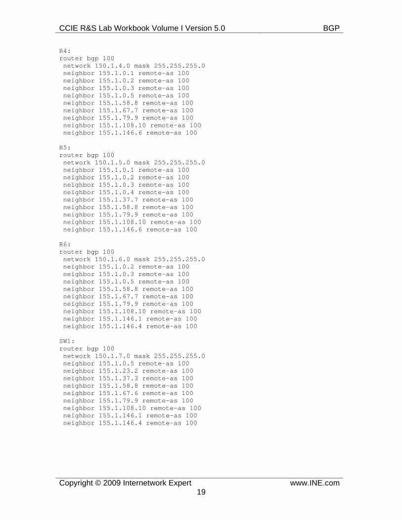
R4: router bgp 100 network 150.1.4.0 mask 255.255.255.0 neighbor 155.1.0.1 remote-as 100 neighbor 155.1.0.2 remote-as 100 neighbor 155.1.0.3 remote-as 100 neighbor 155.1.0.5 remote-as 100 neighbor 155.1.58.8 remote-as 100 neighbor 155.1.67.7 remote-as 100 neighbor 155.1.79.9 remote-as 100 neighbor 155.1.108.10 remote-as 100 neighbor 155.1.146.6 remote-as 100
R5: router bgp 100 network 150.1.5.0 mask 255.255.255.0 neighbor 155.1.0.1 remote-as 100 neighbor 155.1.0.2 remote-as 100 neighbor 155.1.0.3 remote-as 100 neighbor 155.1.0.4 remote-as 100 neighbor 155.1.37.7 remote-as 100 neighbor 155.1.58.8 remote-as 100 neighbor 155.1.79.9 remote-as 100 neighbor 155.1.108.10 remote-as 100 neighbor 155.1.146.6 remote-as 100 R6: router bgp 100 network 150.1.6.0 mask 255.255.255.0 neighbor 155.1.0.2 remote-as 100 neighbor 155.1.0.3 remote-as 100 neighbor 155.1.0.5 remote-as 100 neighbor 155.1.58.8 remote-as 100 neighbor 155.1.67.7 remote-as 100 neighbor 155.1.79.9 remote-as 100 neighbor 155.1.108.10 remote-as 100 neighbor 155.1.146.1 remote-as 100 neighbor 155.1.146.4 remote-as 100
SW1: router bgp 100 network 150.1.7.0 mask 255.255.255.0 neighbor 155.1.0.5 remote-as 100 neighbor 155.1.23.2 remote-as 100 neighbor 155.1.37.3 remote-as 100 neighbor 155.1.58.8 remote-as 100 neighbor 155.1.67.6 remote-as 100 neighbor 155.1.79.9 remote-as 100 neighbor 155.1.108.10 remote-as 100 neighbor 155.1.146.1 remote-as 100 neighbor 155.1.146.4 remote-as 100
CCIE R&S Lab Workbook Volume I Version 5.0 BGP
Copyright © 2009 Internetwork Expert www.INE.com20
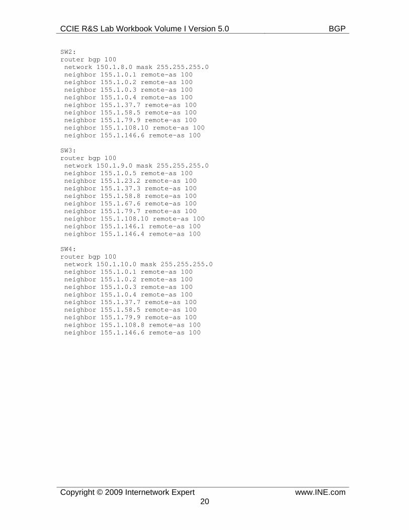
SW2: router bgp 100 network 150.1.8.0 mask 255.255.255.0 neighbor 155.1.0.1 remote-as 100 neighbor 155.1.0.2 remote-as 100 neighbor 155.1.0.3 remote-as 100 neighbor 155.1.0.4 remote-as 100 neighbor 155.1.37.7 remote-as 100 neighbor 155.1.58.5 remote-as 100 neighbor 155.1.79.9 remote-as 100 neighbor 155.1.108.10 remote-as 100 neighbor 155.1.146.6 remote-as 100 SW3: router bgp 100 network 150.1.9.0 mask 255.255.255.0 neighbor 155.1.0.5 remote-as 100 neighbor 155.1.23.2 remote-as 100 neighbor 155.1.37.3 remote-as 100 neighbor 155.1.58.8 remote-as 100 neighbor 155.1.67.6 remote-as 100 neighbor 155.1.79.7 remote-as 100 neighbor 155.1.108.10 remote-as 100 neighbor 155.1.146.1 remote-as 100 neighbor 155.1.146.4 remote-as 100
SW4: router bgp 100 network 150.1.10.0 mask 255.255.255.0 neighbor 155.1.0.1 remote-as 100 neighbor 155.1.0.2 remote-as 100 neighbor 155.1.0.3 remote-as 100 neighbor 155.1.0.4 remote-as 100 neighbor 155.1.37.7 remote-as 100 neighbor 155.1.58.5 remote-as 100 neighbor 155.1.79.9 remote-as 100 neighbor 155.1.108.8 remote-as 100 neighbor 155.1.146.6 remote-as 100
CCIE R&S Lab Workbook Volume I Version 5.0 BGP
Copyright © 2009 Internetwork Expert www.INE.com21
Verification
Note
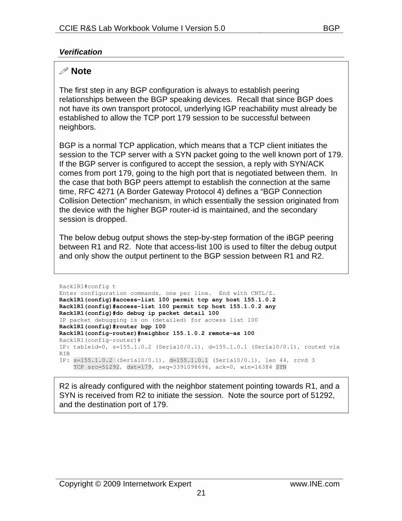
The first step in any BGP configuration is always to establish peering relationships between the BGP speaking devices. Recall that since BGP does not have its own transport protocol, underlying IGP reachability must already be established to allow the TCP port 179 session to be successful between neighbors.
BGP is a normal TCP application, which means that a TCP client initiates the session to the TCP server with a SYN packet going to the well known port of 179. If the BGP server is configured to accept the session, a reply with SYN/ACK comes from port 179, going to the high port that is negotiated between them. In the case that both BGP peers attempt to establish the connection at the same time, RFC 4271 (A Border Gateway Protocol 4) defines a “BGP Connection Collision Detection” mechanism, in which essentially the session originated from the device with the higher BGP router-id is maintained, and the secondary session is dropped.
The below debug output shows the step-by-step formation of the iBGP peering between R1 and R2. Note that access-list 100 is used to filter the debug output and only show the output pertinent to the BGP session between R1 and R2.
Rack1R1#config t Enter configuration commands, one per line. End with CNTL/Z. Rack1R1(config)#access-list 100 permit tcp any host 155.1.0.2 Rack1R1(config)#access-list 100 permit tcp host 155.1.0.2 any Rack1R1(config)#do debug ip packet detail 100 IP packet debugging is on (detailed) for access list 100 Rack1R1(config)#router bgp 100 Rack1R1(config-router)#neighbor 155.1.0.2 remote-as 100 Rack1R1(config-router)# IP: tableid=0, s=155.1.0.2 (Serial0/0.1), d=155.1.0.1 (Serial0/0.1), routed via RIB IP: s=155.1.0.2 (Serial0/0.1), d=155.1.0.1 (Serial0/0.1), len 44, rcvd 3 TCP src=51292, dst=179, seq=3391098696, ack=0, win=16384 SYN
R2 is already configured with the neighbor statement pointing towards R1, and a SYN is received from R2 to initiate the session. Note the source port of 51292, and the destination port of 179.
CCIE R&S Lab Workbook Volume I Version 5.0 BGP
Copyright © 2009 Internetwork Expert www.INE.com22
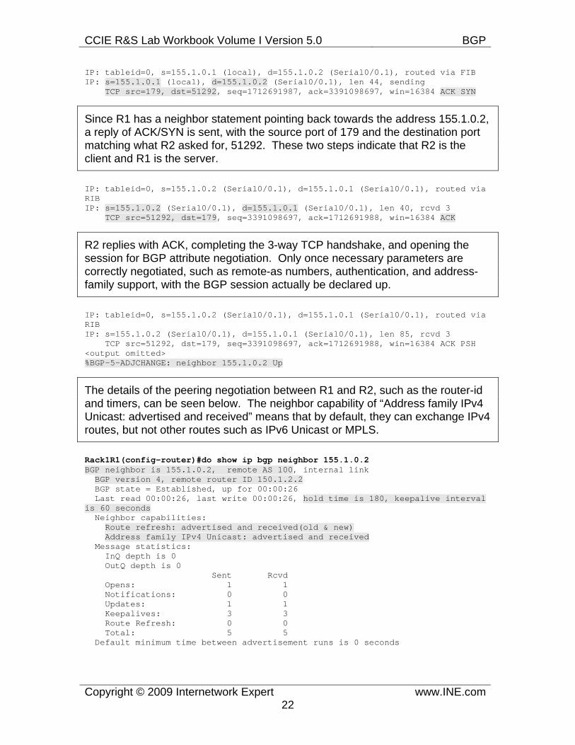
IP: tableid=0, s=155.1.0.1 (local), d=155.1.0.2 (Serial0/0.1), routed via FIB IP: s=155.1.0.1 (local), d=155.1.0.2 (Serial0/0.1), len 44, sending TCP src=179, dst=51292, seq=1712691987, ack=3391098697, win=16384 ACK SYN
Since R1 has a neighbor statement pointing back towards the address 155.1.0.2, a reply of ACK/SYN is sent, with the source port of 179 and the destination port matching what R2 asked for, 51292. These two steps indicate that R2 is the client and R1 is the server.
IP: tableid=0, s=155.1.0.2 (Serial0/0.1), d=155.1.0.1 (Serial0/0.1), routed via RIB IP: s=155.1.0.2 (Serial0/0.1), d=155.1.0.1 (Serial0/0.1), len 40, rcvd 3 TCP src=51292, dst=179, seq=3391098697, ack=1712691988, win=16384 ACK
R2 replies with ACK, completing the 3-way TCP handshake, and opening the session for BGP attribute negotiation. Only once necessary parameters are correctly negotiated, such as remote-as numbers, authentication, and address-family support, with the BGP session actually be declared up.
IP: tableid=0, s=155.1.0.2 (Serial0/0.1), d=155.1.0.1 (Serial0/0.1), routed via RIB IP: s=155.1.0.2 (Serial0/0.1), d=155.1.0.1 (Serial0/0.1), len 85, rcvd 3 TCP src=51292, dst=179, seq=3391098697, ack=1712691988, win=16384 ACK PSH <output omitted> %BGP-5-ADJCHANGE: neighbor 155.1.0.2 Up
The details of the peering negotiation between R1 and R2, such as the router-id and timers, can be seen below. The neighbor capability of “Address family IPv4 Unicast: advertised and received” means that by default, they can exchange IPv4 routes, but not other routes such as IPv6 Unicast or MPLS.
Rack1R1(config-router)#do show ip bgp neighbor 155.1.0.2 BGP neighbor is 155.1.0.2, remote AS 100, internal link BGP version 4, remote router ID 150.1.2.2 BGP state = Established, up for 00:00:26 Last read 00:00:26, last write 00:00:26, hold time is 180, keepalive interval is 60 seconds Neighbor capabilities: Route refresh: advertised and received(old & new) Address family IPv4 Unicast: advertised and received Message statistics: InQ depth is 0 OutQ depth is 0 Sent Rcvd Opens: 1 1 Notifications: 0 0 Updates: 1 1 Keepalives: 3 3 Route Refresh: 0 0 Total: 5 5 Default minimum time between advertisement runs is 0 seconds
CCIE R&S Lab Workbook Volume I Version 5.0 BGP
Copyright © 2009 Internetwork Expert www.INE.com23
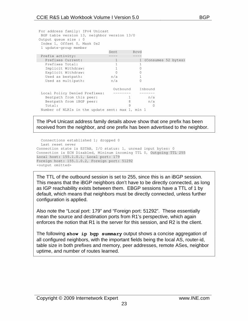
For address family: IPv4 Unicast BGP table version 13, neighbor version 13/0 Output queue size : 0 Index 1, Offset 0, Mask 0x2 1 update-group member Sent Rcvd Prefix activity: ---- ---- Prefixes Current: 1 1 (Consumes 52 bytes) Prefixes Total: 1 1 Implicit Withdraw: 1 0 Explicit Withdraw: 0 0 Used as bestpath: n/a 1 Used as multipath: n/a 0
Outbound Inbound Local Policy Denied Prefixes: -------- ------- Bestpath from this peer: 1 n/a Bestpath from iBGP peer: 8 n/a Total: 9 0 Number of NLRIs in the update sent: max 1, min 1
The IPv4 Unicast address family details above show that one prefix has been received from the neighbor, and one prefix has been advertised to the neighbor.
Connections established 1; dropped 0 Last reset never Connection state is ESTAB, I/O status: 1, unread input bytes: 0 Connection is ECN Disabled, Mininum incoming TTL 0, Outgoing TTL 255 Local host: 155.1.0.1, Local port: 179 Foreign host: 155.1.0.2, Foreign port: 51292 <output omitted>
The TTL of the outbound session is set to 255, since this is an iBGP session. This means that the iBGP neighbors don’t have to be directly connected, as long as IGP reachability exists between them. EBGP sessions have a TTL of 1 by default, which means that neighbors must be directly connected, unless further configuration is applied.
Also note the “Local port: 179” and “Foreign port: 51292”. These essentially mean the source and destination ports from R1’s perspective, which again enforces the notion that R1 is the server for this session, and R2 is the client.
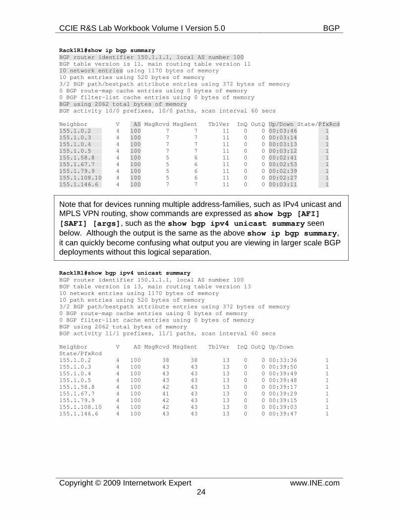
The following show ip bgp summary output shows a concise aggregation of all configured neighbors, with the important fields being the local AS, router-id, table size in both prefixes and memory, peer addresses, remote ASes, neighbor uptime, and number of routes learned.
CCIE R&S Lab Workbook Volume I Version 5.0 BGP
Copyright © 2009 Internetwork Expert www.INE.com24
Rack1R1#show ip bgp summary BGP router identifier 150.1.1.1, local AS number 100 BGP table version is 11, main routing table version 11 10 network entries using 1170 bytes of memory 10 path entries using 520 bytes of memory 3/2 BGP path/bestpath attribute entries using 372 bytes of memory 0 BGP route-map cache entries using 0 bytes of memory 0 BGP filter-list cache entries using 0 bytes of memory BGP using 2062 total bytes of memory BGP activity 10/0 prefixes, 10/0 paths, scan interval 60 secs
Neighbor V AS MsgRcvd MsgSent TblVer InQ OutQ Up/Down State/PfxRcd 155.1.0.2 4 100 7 7 11 0 0 00:03:46 1 155.1.0.3 4 100 7 7 11 0 0 00:03:14 1 155.1.0.4 4 100 7 7 11 0 0 00:03:13 1 155.1.0.5 4 100 7 7 11 0 0 00:03:12 1 155.1.58.8 4 100 5 6 11 0 0 00:02:41 1 155.1.67.7 4 100 5 6 11 0 0 00:02:53 1 155.1.79.9 4 100 5 6 11 0 0 00:02:39 1 155.1.108.10 4 100 5 6 11 0 0 00:02:27 1 155.1.146.6 4 100 7 7 11 0 0 00:03:11 1
Note that for devices running multiple address-families, such as IPv4 unicast and MPLS VPN routing, show commands are expressed as show bgp [AFI] [SAFI] [args], such as the show bgp ipv4 unicast summary seen below. Although the output is the same as the above show ip bgp summary, it can quickly become confusing what output you are viewing in larger scale BGP deployments without this logical separation.
Rack1R1#show bgp ipv4 unicast summary BGP router identifier 150.1.1.1, local AS number 100 BGP table version is 13, main routing table version 13 10 network entries using 1170 bytes of memory 10 path entries using 520 bytes of memory 3/2 BGP path/bestpath attribute entries using 372 bytes of memory 0 BGP route-map cache entries using 0 bytes of memory 0 BGP filter-list cache entries using 0 bytes of memory BGP using 2062 total bytes of memory BGP activity 11/1 prefixes, 11/1 paths, scan interval 60 secs
Neighbor V AS MsgRcvd MsgSent TblVer InQ OutQ Up/Down State/PfxRcd 155.1.0.2 4 100 38 38 13 0 0 00:33:36 1 155.1.0.3 4 100 43 43 13 0 0 00:39:50 1 155.1.0.4 4 100 43 43 13 0 0 00:39:49 1 155.1.0.5 4 100 43 43 13 0 0 00:39:48 1 155.1.58.8 4 100 42 43 13 0 0 00:39:17 1 155.1.67.7 4 100 41 43 13 0 0 00:39:29 1 155.1.79.9 4 100 42 43 13 0 0 00:39:15 1 155.1.108.10 4 100 42 43 13 0 0 00:39:03 1 155.1.146.6 4 100 43 43 13 0 0 00:39:47 1
CCIE R&S Lab Workbook Volume I Version 5.0 BGP
Copyright © 2009 Internetwork Expert www.INE.com25
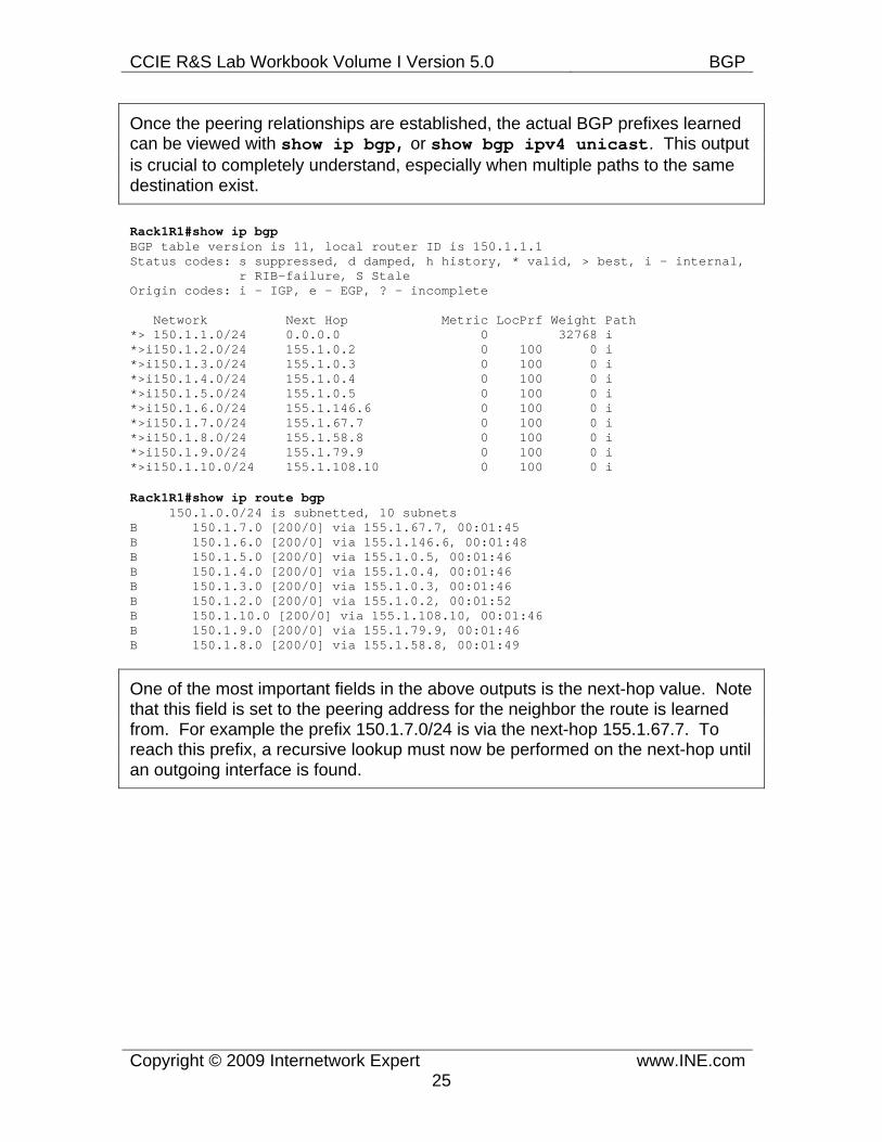
Once the peering relationships are established, the actual BGP prefixes learned can be viewed with show ip bgp, or show bgp ipv4 unicast. This output is crucial to completely understand, especially when multiple paths to the same destination exist.
Rack1R1#show ip bgp BGP table version is 11, local router ID is 150.1.1.1 Status codes: s suppressed, d damped, h history, * valid, > best, i - internal, r RIB-failure, S Stale Origin codes: i - IGP, e - EGP, ? - incomplete
Network Next Hop Metric LocPrf Weight Path *> 150.1.1.0/24 0.0.0.0 0 32768 i *>i150.1.2.0/24 155.1.0.2 0 100 0 i *>i150.1.3.0/24 155.1.0.3 0 100 0 i *>i150.1.4.0/24 155.1.0.4 0 100 0 i *>i150.1.5.0/24 155.1.0.5 0 100 0 i *>i150.1.6.0/24 155.1.146.6 0 100 0 i *>i150.1.7.0/24 155.1.67.7 0 100 0 i *>i150.1.8.0/24 155.1.58.8 0 100 0 i *>i150.1.9.0/24 155.1.79.9 0 100 0 i *>i150.1.10.0/24 155.1.108.10 0 100 0 i
Rack1R1#show ip route bgp 150.1.0.0/24 is subnetted, 10 subnets B 150.1.7.0 [200/0] via 155.1.67.7, 00:01:45 B 150.1.6.0 [200/0] via 155.1.146.6, 00:01:48 B 150.1.5.0 [200/0] via 155.1.0.5, 00:01:46 B 150.1.4.0 [200/0] via 155.1.0.4, 00:01:46 B 150.1.3.0 [200/0] via 155.1.0.3, 00:01:46 B 150.1.2.0 [200/0] via 155.1.0.2, 00:01:52 B 150.1.10.0 [200/0] via 155.1.108.10, 00:01:46 B 150.1.9.0 [200/0] via 155.1.79.9, 00:01:46 B 150.1.8.0 [200/0] via 155.1.58.8, 00:01:49
One of the most important fields in the above outputs is the next-hop value. Note that this field is set to the peering address for the neighbor the route is learned from. For example the prefix 150.1.7.0/24 is via the next-hop 155.1.67.7. To reach this prefix, a recursive lookup must now be performed on the next-hop until an outgoing interface is found.
CCIE R&S Lab Workbook Volume I Version 5.0 BGP
Copyright © 2009 Internetwork Expert www.INE.com26
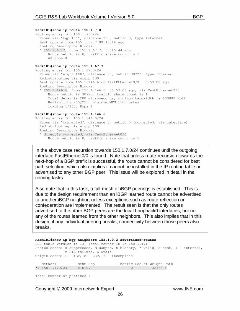
Rack1R1#show ip route 150.1.7.0 Routing entry for 150.1.7.0/24 Known via "bgp 100", distance 200, metric 0, type internal Last update from 155.1.67.7 00:45:44 ago Routing Descriptor Blocks: * 155.1.67.7, from 155.1.67.7, 00:45:44 ago Route metric is 0, traffic share count is 1 AS Hops 0
Rack1R1#show ip route 155.1.67.7 Routing entry for 155.1.67.0/24 Known via "eigrp 100", distance 90, metric 30720, type internal Redistributing via eigrp 100 Last update from 155.1.146.6 on FastEthernet0/0, 00:53:08 ago Routing Descriptor Blocks: * 155.1.146.6, from 155.1.146.6, 00:53:08 ago, via FastEthernet0/0 Route metric is 30720, traffic share count is 1 Total delay is 200 microseconds, minimum bandwidth is 100000 Kbit Reliability 255/255, minimum MTU 1500 bytes Loading 1/255, Hops 1
Rack1R1#show ip route 155.1.146.6 Routing entry for 155.1.146.0/24 Known via "connected", distance 0, metric 0 (connected, via interface) Redistributing via eigrp 100 Routing Descriptor Blocks: * directly connected, via FastEthernet0/0 Route metric is 0, traffic share count is 1
In the above case recursion towards 150.1.7.0/24 continues until the outgoing interface FastEthernet0/0 is found. Note that unless route-recursion towards the next-hop of a BGP prefix is successful, the route cannot be considered for best path selection, which also implies it cannot be installed in the IP routing table or advertised to any other BGP peer. This issue will be explored in detail in the coming tasks.
Also note that in this task, a full-mesh of iBGP peerings is established. This is due to the design requirement than an iBGP learned route cannot be advertised to another iBGP neighbor, unless exceptions such as route-reflection or confederation are implemented. The result seen is that the only routes advertised to the other BGP peers are the local Loopback0 interfaces, but not any of the routes learned from the other neighbors. This also implies that in this design, if any individual peering breaks, connectivity between those peers also breaks.
Rack1R1#show ip bgp neighbors 155.1.0.2 advertised-routes BGP table version is 13, local router ID is 150.1.1.1 Status codes: s suppressed, d damped, h history, * valid, > best, i - internal, r RIB-failure, S Stale Origin codes: i - IGP, e - EGP, ? - incomplete
Network Next Hop Metric LocPrf Weight Path *> 150.1.1.0/24 0.0.0.0 0 32768 i
Total number of prefixes 1
CCIE R&S Lab Workbook Volume I Version 5.0 BGP
Copyright © 2009 Internetwork Expert www.INE.com27
7.2 Establishing EBGP Peerings • BB1 and BB3 are in AS 54. • Configure EBGP peerings between R4 & BB3 and R6 & BB1 using their
directly connected links. • Advertise the external links between R4 & BB3 and R6 & BB1 into IGP. • Ensure full reachability to all prefixes learned from AS 54 from all internal
devices when sourcing traffic from the Loopback0 interfaces.
Configuration R4: router eigrp 100 passive-interface FastEthernet0/0 network 204.12.1.0 ! router bgp 100 neighbor 204.12.1.254 remote-as 54
R6: router eigrp 100 passive-interface Serial0/0 network 54.0.0.0 ! router bgp 100 neighbor 54.1.1.254 remote-as 54
Verification
Note
Configuration-wise, the only difference between an iBGP peering and an EBGP peering is that with an EBGP peering, the remote-as is different than the local-as. In practice however, many important attributes differ between the two. As seen in the following output, R4 knows that the peering occurs on a directly connected external link, and that the TTL should be 1 instead of 255. This implies that the neighbors must be directly connected for peering to be established, otherwise the TTL would exceed in transit and the TCP frames would be dropped.
Rack1R4#show ip bgp neighbors 204.12.1.254 BGP neighbor is 204.12.1.254, remote AS 54, external link BGP version 4, remote router ID 31.3.0.1 BGP state = Established, up for 00:02:04 <output omitted>
Connection is ECN Disabled, Mininum incoming TTL 0, Outgoing TTL 1 Local host: 204.12.1.4, Local port: 179 Foreign host: 204.12.1.254, Foreign port: 31806 <output omitted>
CCIE R&S Lab Workbook Volume I Version 5.0 BGP
Copyright © 2009 Internetwork Expert www.INE.com28
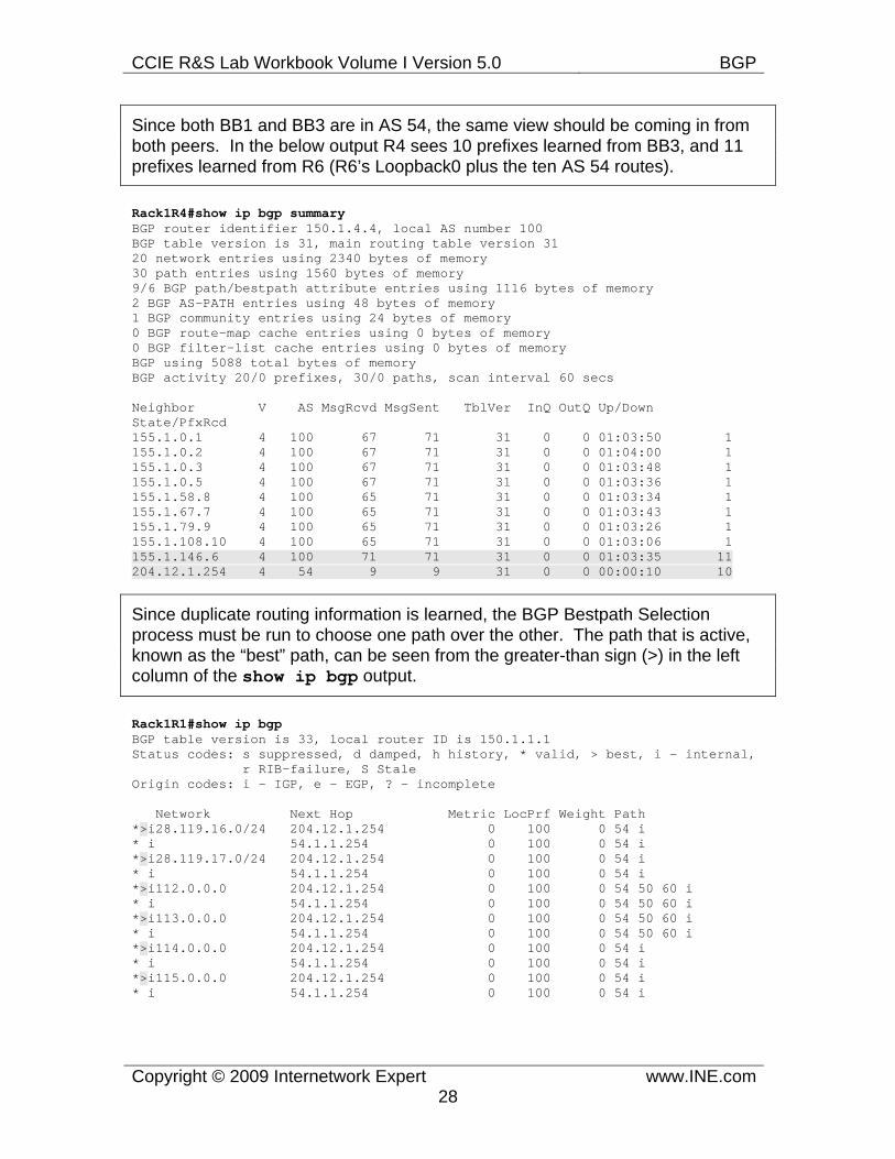
Since both BB1 and BB3 are in AS 54, the same view should be coming in from both peers. In the below output R4 sees 10 prefixes learned from BB3, and 11 prefixes learned from R6 (R6’s Loopback0 plus the ten AS 54 routes).
Rack1R4#show ip bgp summary BGP router identifier 150.1.4.4, local AS number 100 BGP table version is 31, main routing table version 31 20 network entries using 2340 bytes of memory 30 path entries using 1560 bytes of memory 9/6 BGP path/bestpath attribute entries using 1116 bytes of memory 2 BGP AS-PATH entries using 48 bytes of memory 1 BGP community entries using 24 bytes of memory 0 BGP route-map cache entries using 0 bytes of memory 0 BGP filter-list cache entries using 0 bytes of memory BGP using 5088 total bytes of memory BGP activity 20/0 prefixes, 30/0 paths, scan interval 60 secs
Neighbor V AS MsgRcvd MsgSent TblVer InQ OutQ Up/Down State/PfxRcd 155.1.0.1 4 100 67 71 31 0 0 01:03:50 1 155.1.0.2 4 100 67 71 31 0 0 01:04:00 1 155.1.0.3 4 100 67 71 31 0 0 01:03:48 1 155.1.0.5 4 100 67 71 31 0 0 01:03:36 1 155.1.58.8 4 100 65 71 31 0 0 01:03:34 1 155.1.67.7 4 100 65 71 31 0 0 01:03:43 1 155.1.79.9 4 100 65 71 31 0 0 01:03:26 1 155.1.108.10 4 100 65 71 31 0 0 01:03:06 1 155.1.146.6 4 100 71 71 31 0 0 01:03:35 11 204.12.1.254 4 54 9 9 31 0 0 00:00:10 10
Since duplicate routing information is learned, the BGP Bestpath Selection process must be run to choose one path over the other. The path that is active, known as the “best” path, can be seen from the greater-than sign (>) in the left column of the show ip bgp output.
Rack1R1#show ip bgp BGP table version is 33, local router ID is 150.1.1.1 Status codes: s suppressed, d damped, h history, * valid, > best, i - internal, r RIB-failure, S Stale Origin codes: i - IGP, e - EGP, ? - incomplete
Network Next Hop Metric LocPrf Weight Path *>i28.119.16.0/24 204.12.1.254 0 100 0 54 i * i 54.1.1.254 0 100 0 54 i *>i28.119.17.0/24 204.12.1.254 0 100 0 54 i * i 54.1.1.254 0 100 0 54 i *>i112.0.0.0 204.12.1.254 0 100 0 54 50 60 i * i 54.1.1.254 0 100 0 54 50 60 i *>i113.0.0.0 204.12.1.254 0 100 0 54 50 60 i * i 54.1.1.254 0 100 0 54 50 60 i *>i114.0.0.0 204.12.1.254 0 100 0 54 i * i 54.1.1.254 0 100 0 54 i *>i115.0.0.0 204.12.1.254 0 100 0 54 i * i 54.1.1.254 0 100 0 54 i
CCIE R&S Lab Workbook Volume I Version 5.0 BGP
Copyright © 2009 Internetwork Expert www.INE.com29
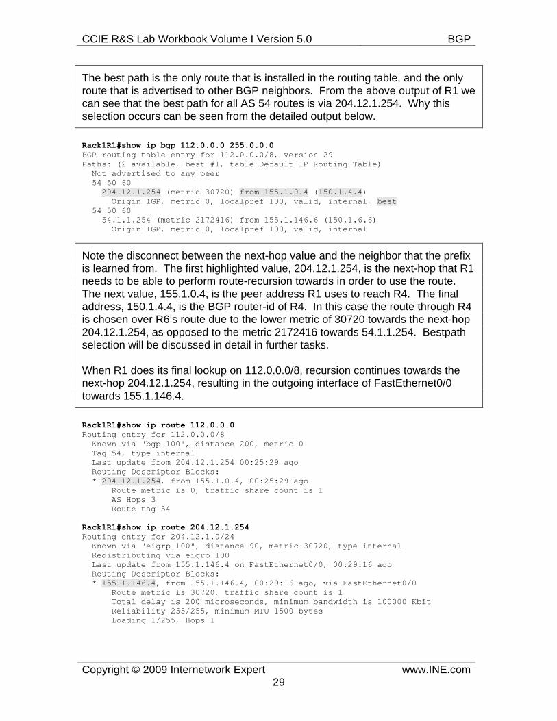
The best path is the only route that is installed in the routing table, and the only route that is advertised to other BGP neighbors. From the above output of R1 we can see that the best path for all AS 54 routes is via 204.12.1.254. Why this selection occurs can be seen from the detailed output below.
Rack1R1#show ip bgp 112.0.0.0 255.0.0.0 BGP routing table entry for 112.0.0.0/8, version 29 Paths: (2 available, best #1, table Default-IP-Routing-Table) Not advertised to any peer 54 50 60 204.12.1.254 (metric 30720) from 155.1.0.4 (150.1.4.4) Origin IGP, metric 0, localpref 100, valid, internal, best 54 50 60 54.1.1.254 (metric 2172416) from 155.1.146.6 (150.1.6.6) Origin IGP, metric 0, localpref 100, valid, internal
Note the disconnect between the next-hop value and the neighbor that the prefix is learned from. The first highlighted value, 204.12.1.254, is the next-hop that R1 needs to be able to perform route-recursion towards in order to use the route. The next value, 155.1.0.4, is the peer address R1 uses to reach R4. The final address, 150.1.4.4, is the BGP router-id of R4. In this case the route through R4 is chosen over R6’s route due to the lower metric of 30720 towards the next-hop 204.12.1.254, as opposed to the metric 2172416 towards 54.1.1.254. Bestpath selection will be discussed in detail in further tasks.
When R1 does its final lookup on 112.0.0.0/8, recursion continues towards the next-hop 204.12.1.254, resulting in the outgoing interface of FastEthernet0/0 towards 155.1.146.4.
Rack1R1#show ip route 112.0.0.0 Routing entry for 112.0.0.0/8 Known via "bgp 100", distance 200, metric 0 Tag 54, type internal Last update from 204.12.1.254 00:25:29 ago Routing Descriptor Blocks: * 204.12.1.254, from 155.1.0.4, 00:25:29 ago Route metric is 0, traffic share count is 1 AS Hops 3 Route tag 54
Rack1R1#show ip route 204.12.1.254 Routing entry for 204.12.1.0/24 Known via "eigrp 100", distance 90, metric 30720, type internal Redistributing via eigrp 100 Last update from 155.1.146.4 on FastEthernet0/0, 00:29:16 ago Routing Descriptor Blocks: * 155.1.146.4, from 155.1.146.4, 00:29:16 ago, via FastEthernet0/0 Route metric is 30720, traffic share count is 1 Total delay is 200 microseconds, minimum bandwidth is 100000 Kbit Reliability 255/255, minimum MTU 1500 bytes Loading 1/255, Hops 1
CCIE R&S Lab Workbook Volume I Version 5.0 BGP
Copyright © 2009 Internetwork Expert www.INE.com30
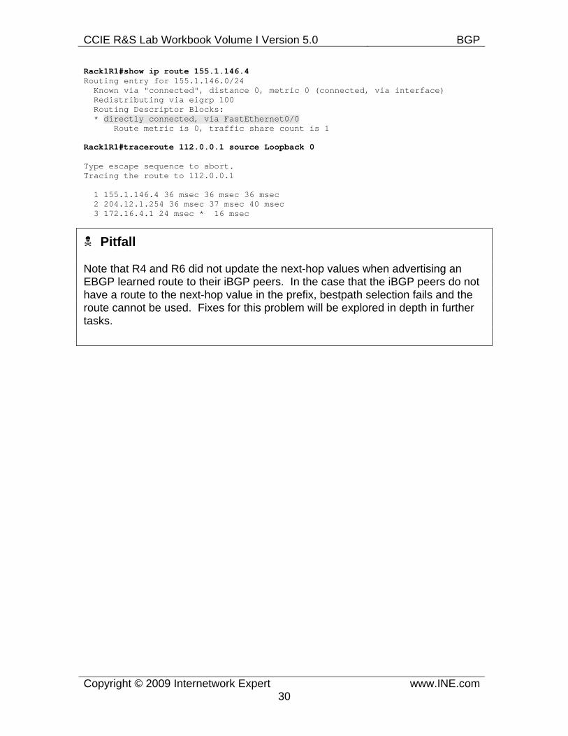
Rack1R1#show ip route 155.1.146.4 Routing entry for 155.1.146.0/24 Known via "connected", distance 0, metric 0 (connected, via interface) Redistributing via eigrp 100 Routing Descriptor Blocks: * directly connected, via FastEthernet0/0 Route metric is 0, traffic share count is 1
Rack1R1#traceroute 112.0.0.1 source Loopback 0
Type escape sequence to abort. Tracing the route to 112.0.0.1
1 155.1.146.4 36 msec 36 msec 36 msec 2 204.12.1.254 36 msec 37 msec 40 msec 3 172.16.4.1 24 msec * 16 msec
Pitfall
Note that R4 and R6 did not update the next-hop values when advertising an EBGP learned route to their iBGP peers. In the case that the iBGP peers do not have a route to the next-hop value in the prefix, bestpath selection fails and the route cannot be used. Fixes for this problem will be explored in depth in further tasks.
CCIE R&S Lab Workbook Volume I Version 5.0 BGP
Copyright © 2009 Internetwork Expert www.INE.com31
7.3 BGP Update Source Modification • Advertise the Loopback0 interfaces of R4 and R5 into IGP. • Modify the BGP peering between these devices so that if either the Frame
Relay or Point-to-Point Serial link between them goes down, the BGP peering is not affected.
Configuration R4: router eigrp 100 network 150.1.0.0 ! router bgp 100 neighbor 150.1.5.5 remote-as 100 neighbor 150.1.5.5 update-source Loopback0
R5: router eigrp 100 network 150.1.0.0 ! router bgp 100 neighbor 150.1.4.4 remote-as 100 neighbor 150.1.4.4 update-source Loopback0
Verification
Note
Since BGP peerings use TCP for transport, it is not a requirement that neighbors be directly connected. When neighbors are not directly connected, the choice of IP addresses used in peering can greatly affect the redundancy design of a BGP network. In the previous case, the peering between R4 and R5 was configured using their connected Frame Relay interface IP addresses. This implies that if the Frame Relay link were to go down, the BGP peering would also go down, even if alternate routes still existed between the devices. To fix this redundancy issue, the update-source for a BGP peering session can be changed on a per-neighbor basis.
CCIE R&S Lab Workbook Volume I Version 5.0 BGP
Copyright © 2009 Internetwork Expert www.INE.com32
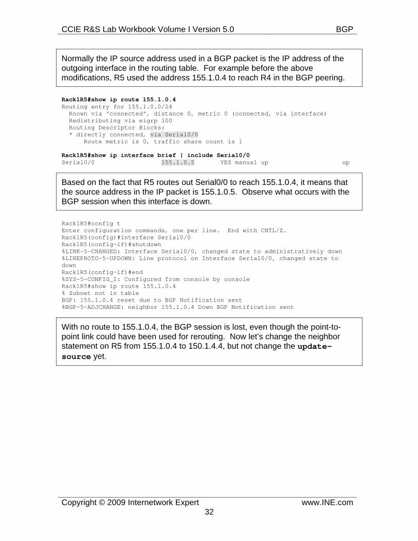
Normally the IP source address used in a BGP packet is the IP address of the outgoing interface in the routing table. For example before the above modifications, R5 used the address 155.1.0.4 to reach R4 in the BGP peering.
Rack1R5#show ip route 155.1.0.4 Routing entry for 155.1.0.0/24 Known via "connected", distance 0, metric 0 (connected, via interface) Redistributing via eigrp 100 Routing Descriptor Blocks: * directly connected, via Serial0/0 Route metric is 0, traffic share count is 1
Rack1R5#show ip interface brief | include Serial0/0 Serial0/0 155.1.0.5 YES manual up up
Based on the fact that R5 routes out Serial0/0 to reach 155.1.0.4, it means that the source address in the IP packet is 155.1.0.5. Observe what occurs with the BGP session when this interface is down.
Rack1R5#config t Enter configuration commands, one per line. End with CNTL/Z. Rack1R5(config)#interface Serial0/0 Rack1R5(config-if)#shutdown %LINK-5-CHANGED: Interface Serial0/0, changed state to administratively down %LINEPROTO-5-UPDOWN: Line protocol on Interface Serial0/0, changed state to down Rack1R5(config-if)#end %SYS-5-CONFIG_I: Configured from console by console Rack1R5#show ip route 155.1.0.4 % Subnet not in table BGP: 155.1.0.4 reset due to BGP Notification sent %BGP-5-ADJCHANGE: neighbor 155.1.0.4 Down BGP Notification sent
With no route to 155.1.0.4, the BGP session is lost, even though the point-to-point link could have been used for rerouting. Now let’s change the neighbor statement on R5 from 155.1.0.4 to 150.1.4.4, but not change the update-source yet.
CCIE R&S Lab Workbook Volume I Version 5.0 BGP
Copyright © 2009 Internetwork Expert www.INE.com33
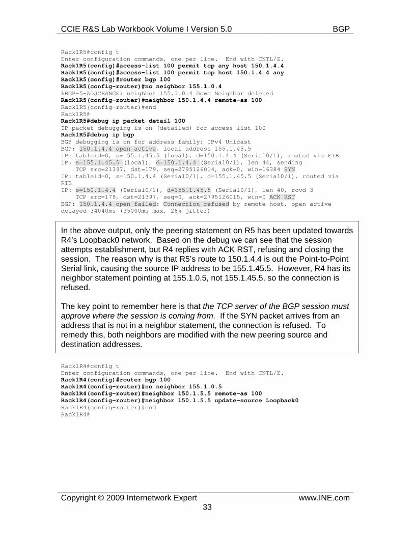
Rack1R5#config t Enter configuration commands, one per line. End with CNTL/Z. Rack1R5(config)#access-list 100 permit tcp any host 150.1.4.4 Rack1R5(config)#access-list 100 permit tcp host 150.1.4.4 any Rack1R5(config)#router bgp 100 Rack1R5(config-router)#no neighbor 155.1.0.4 %BGP-5-ADJCHANGE: neighbor 155.1.0.4 Down Neighbor deleted Rack1R5(config-router)#neighbor 150.1.4.4 remote-as 100 Rack1R5(config-router)#end Rack1R5# Rack1R5#debug ip packet detail 100 IP packet debugging is on (detailed) for access list 100 Rack1R5#debug ip bgp BGP debugging is on for address family: IPv4 Unicast BGP: 150.1.4.4 open active, local address 155.1.45.5 IP: tableid=0, s=155.1.45.5 (local), d=150.1.4.4 (Serial0/1), routed via FIB IP: s=155.1.45.5 (local), d=150.1.4.4 (Serial0/1), len 44, sending TCP src=21397, dst=179, seq=2795126014, ack=0, win=16384 SYN IP: tableid=0, s=150.1.4.4 (Serial0/1), d=155.1.45.5 (Serial0/1), routed via RIB IP: s=150.1.4.4 (Serial0/1), d=155.1.45.5 (Serial0/1), len 40, rcvd 3 TCP src=179, dst=21397, seq=0, ack=2795126015, win=0 ACK RST BGP: 150.1.4.4 open failed: Connection refused by remote host, open active delayed 34040ms (35000ms max, 28% jitter)
In the above output, only the peering statement on R5 has been updated towards R4’s Loopback0 network. Based on the debug we can see that the session attempts establishment, but R4 replies with ACK RST, refusing and closing the session. The reason why is that R5’s route to 150.1.4.4 is out the Point-to-Point Serial link, causing the source IP address to be 155.1.45.5. However, R4 has its neighbor statement pointing at 155.1.0.5, not 155.1.45.5, so the connection is refused.
The key point to remember here is that the TCP server of the BGP session must approve where the session is coming from. If the SYN packet arrives from an address that is not in a neighbor statement, the connection is refused. To remedy this, both neighbors are modified with the new peering source and destination addresses.
Rack1R4#config t Enter configuration commands, one per line. End with CNTL/Z. Rack1R4(config)#router bgp 100 Rack1R4(config-router)#no neighbor 155.1.0.5 Rack1R4(config-router)#neighbor 150.1.5.5 remote-as 100 Rack1R4(config-router)#neighbor 150.1.5.5 update-source Loopback0 Rack1R4(config-router)#end Rack1R4#
CCIE R&S Lab Workbook Volume I Version 5.0 BGP
Copyright © 2009 Internetwork Expert www.INE.com34
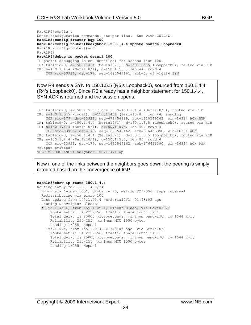
Rack1R5#config t Enter configuration commands, one per line. End with CNTL/Z. Rack1R5(config)#router bgp 100 Rack1R5(config-router)#neighbor 150.1.4.4 update-source Loopback0 Rack1R5(config-router)#end Rack1R5# Rack1R5#debug ip packet detail 100 IP packet debugging is on (detailed) for access list 100 IP: tableid=0, s=150.1.4.4 (Serial0/1), d=150.1.5.5 (Loopback0), routed via RIB IP: s=150.1.4.4 (Serial0/1), d=150.1.5.5, len 44, rcvd 4 TCP src=33926, dst=179, seq=1620549161, ack=0, win=16384 SYN
Now R4 sends a SYN to 150.1.5.5 (R5’s Loopback0), sourced from 150.1.4.4 (R4’s Loopback0). Since R5 already has a neighbor statement for 150.1.4.4, SYN ACK is returned and the session opens.
IP: tableid=0, s=150.1.5.5 (local), d=150.1.4.4 (Serial0/0), routed via FIB IP: s=150.1.5.5 (local), d=150.1.4.4 (Serial0/0), len 44, sending TCP src=179, dst=33926, seq=676456389, ack=1620549162, win=16384 ACK SYN IP: tableid=0, s=150.1.4.4 (Serial0/1), d=150.1.5.5 (Loopback0), routed via RIB IP: s=150.1.4.4 (Serial0/1), d=150.1.5.5, len 40, rcvd 4 TCP src=33926, dst=179, seq=1620549162, ack=676456390, win=16384 ACK IP: tableid=0, s=150.1.4.4 (Serial0/1), d=150.1.5.5 (Loopback0), routed via RIB IP: s=150.1.4.4 (Serial0/1), d=150.1.5.5, len 85, rcvd 4 TCP src=33926, dst=179, seq=1620549162, ack=676456390, win=16384 ACK PSH <output omitted> %BGP-5-ADJCHANGE: neighbor 150.1.4.4 Up
Now if one of the links between the neighbors goes down, the peering is simply rerouted based on the convergence of IGP.
Rack1R5#show ip route 150.1.4.4 Routing entry for 150.1.4.0/24 Known via "eigrp 100", distance 90, metric 2297856, type internal Redistributing via eigrp 100 Last update from 155.1.45.4 on Serial0/1, 01:48:03 ago Routing Descriptor Blocks: * 155.1.45.4, from 155.1.45.4, 01:48:03 ago, via Serial0/1 Route metric is 2297856, traffic share count is 1 Total delay is 25000 microseconds, minimum bandwidth is 1544 Kbit Reliability 255/255, minimum MTU 1500 bytes Loading 1/255, Hops 1 155.1.0.4, from 155.1.0.4, 01:48:03 ago, via Serial0/0 Route metric is 2297856, traffic share count is 1 Total delay is 25000 microseconds, minimum bandwidth is 1544 Kbit Reliability 255/255, minimum MTU 1500 bytes Loading 1/255, Hops 1
CCIE R&S Lab Workbook Volume I Version 5.0 BGP
Copyright © 2009 Internetwork Expert www.INE.com35
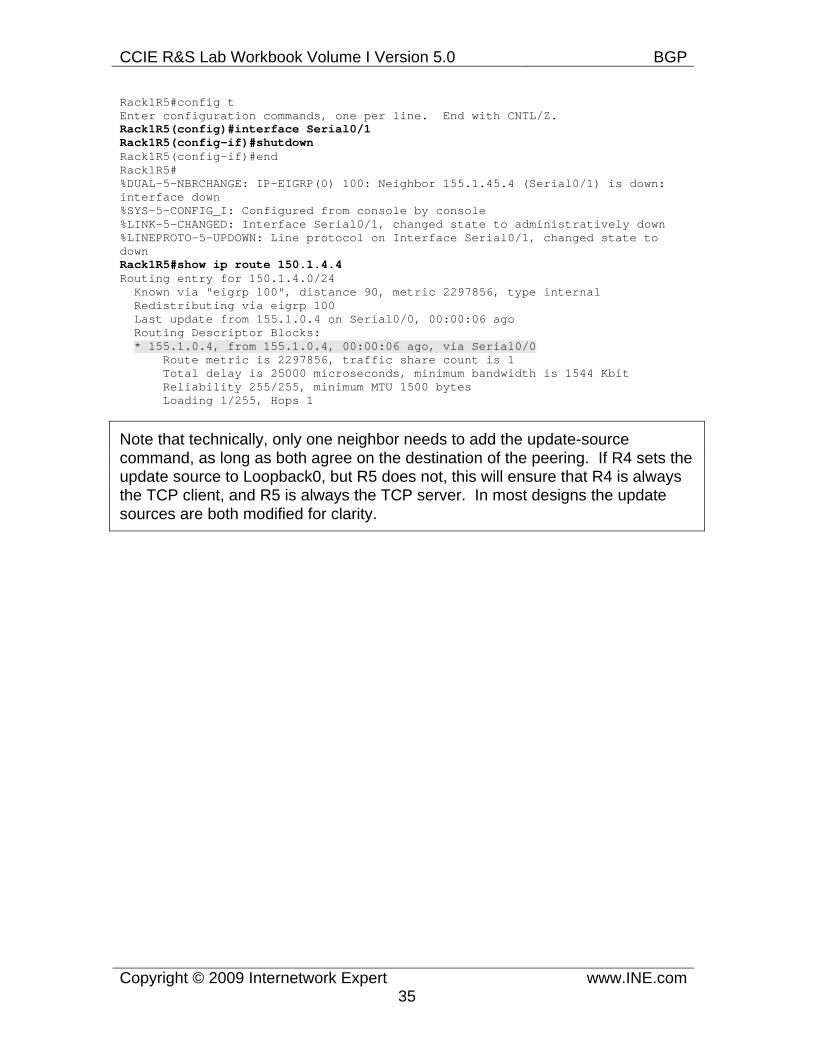
Rack1R5#config t Enter configuration commands, one per line. End with CNTL/Z. Rack1R5(config)#interface Serial0/1 Rack1R5(config-if)#shutdown Rack1R5(config-if)#end Rack1R5# %DUAL-5-NBRCHANGE: IP-EIGRP(0) 100: Neighbor 155.1.45.4 (Serial0/1) is down: interface down %SYS-5-CONFIG_I: Configured from console by console %LINK-5-CHANGED: Interface Serial0/1, changed state to administratively down %LINEPROTO-5-UPDOWN: Line protocol on Interface Serial0/1, changed state to down Rack1R5#show ip route 150.1.4.4 Routing entry for 150.1.4.0/24 Known via "eigrp 100", distance 90, metric 2297856, type internal Redistributing via eigrp 100 Last update from 155.1.0.4 on Serial0/0, 00:00:06 ago Routing Descriptor Blocks: * 155.1.0.4, from 155.1.0.4, 00:00:06 ago, via Serial0/0 Route metric is 2297856, traffic share count is 1 Total delay is 25000 microseconds, minimum bandwidth is 1544 Kbit Reliability 255/255, minimum MTU 1500 bytes Loading 1/255, Hops 1
Note that technically, only one neighbor needs to add the update-source command, as long as both agree on the destination of the peering. If R4 sets the update source to Loopback0, but R5 does not, this will ensure that R4 is always the TCP client, and R5 is always the TCP server. In most designs the update sources are both modified for clarity.
CCIE R&S Lab Workbook Volume I Version 5.0 BGP
Copyright © 2009 Internetwork Expert www.INE.com36
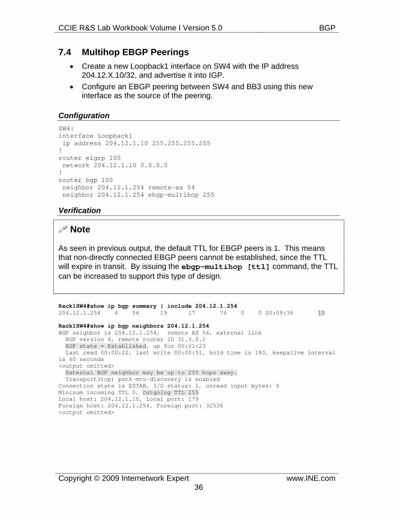
7.4 Multihop EBGP Peerings • Create a new Loopback1 interface on SW4 with the IP address
204.12.X.10/32, and advertise it into IGP. • Configure an EBGP peering between SW4 and BB3 using this new
interface as the source of the peering.
Configuration SW4: interface Loopback1 ip address 204.12.1.10 255.255.255.255 ! router eigrp 100 network 204.12.1.10 0.0.0.0 ! router bgp 100 neighbor 204.12.1.254 remote-as 54 neighbor 204.12.1.254 ebgp-multihop 255
Verification
Note
As seen in previous output, the default TTL for EBGP peers is 1. This means that non-directly connected EBGP peers cannot be established, since the TTL will expire in transit. By issuing the ebgp-multihop [ttl] command, the TTL can be increased to support this type of design.
Rack1SW4#show ip bgp summary | include 204.12.1.254 204.12.1.254 4 54 19 17 74 0 0 00:09:36 10
Rack1SW4#show ip bgp neighbors 204.12.1.254 BGP neighbor is 204.12.1.254, remote AS 54, external link BGP version 4, remote router ID 31.3.0.1 BGP state = Established, up for 00:01:23 Last read 00:00:22, last write 00:00:51, hold time is 180, keepalive interval is 60 seconds <output omitted> External BGP neighbor may be up to 255 hops away. Transport(tcp) path-mtu-discovery is enabled Connection state is ESTAB, I/O status: 1, unread input bytes: 0 Mininum incoming TTL 0, Outgoing TTL 255 Local host: 204.12.1.10, Local port: 179 Foreign host: 204.12.1.254, Foreign port: 32536 <output omitted>
CCIE R&S Lab Workbook Volume I Version 5.0 BGP
Copyright © 2009 Internetwork Expert www.INE.com37
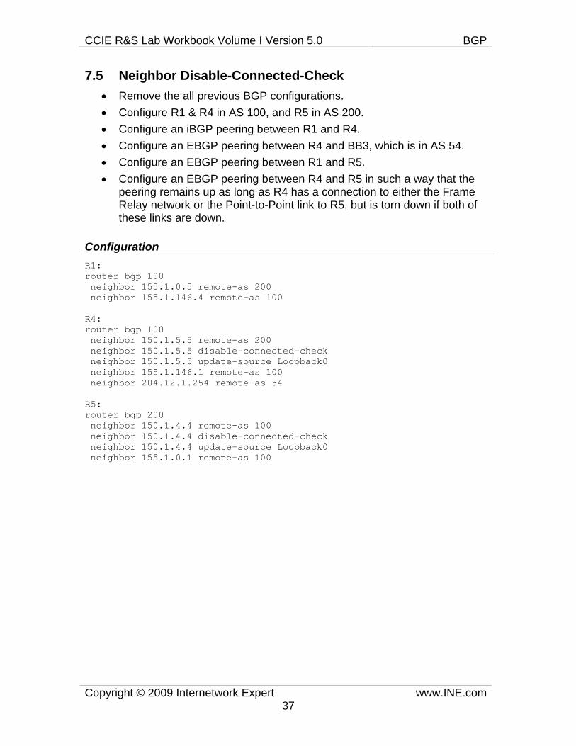
7.5 Neighbor Disable-Connected-Check • Remove the all previous BGP configurations. • Configure R1 & R4 in AS 100, and R5 in AS 200. • Configure an iBGP peering between R1 and R4. • Configure an EBGP peering between R4 and BB3, which is in AS 54. • Configure an EBGP peering between R1 and R5. • Configure an EBGP peering between R4 and R5 in such a way that the
peering remains up as long as R4 has a connection to either the Frame Relay network or the Point-to-Point link to R5, but is torn down if both of these links are down.
Configuration R1: router bgp 100 neighbor 155.1.0.5 remote-as 200 neighbor 155.1.146.4 remote-as 100
R4: router bgp 100 neighbor 150.1.5.5 remote-as 200 neighbor 150.1.5.5 disable-connected-check neighbor 150.1.5.5 update-source Loopback0 neighbor 155.1.146.1 remote-as 100 neighbor 204.12.1.254 remote-as 54
R5: router bgp 200 neighbor 150.1.4.4 remote-as 100 neighbor 150.1.4.4 disable-connected-check neighbor 150.1.4.4 update-source Loopback0 neighbor 155.1.0.1 remote-as 100
CCIE R&S Lab Workbook Volume I Version 5.0 BGP
Copyright © 2009 Internetwork Expert www.INE.com38
Verification
Note
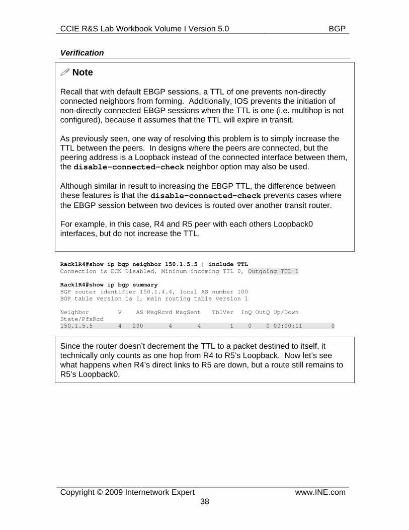
Recall that with default EBGP sessions, a TTL of one prevents non-directly connected neighbors from forming. Additionally, IOS prevents the initiation of non-directly connected EBGP sessions when the TTL is one (i.e. multihop is not configured), because it assumes that the TTL will expire in transit.
As previously seen, one way of resolving this problem is to simply increase the TTL between the peers. In designs where the peers are connected, but the peering address is a Loopback instead of the connected interface between them, the disable-connected-check neighbor option may also be used.
Although similar in result to increasing the EBGP TTL, the difference between these features is that the disable-connected-check prevents cases where the EBGP session between two devices is routed over another transit router.
For example, in this case, R4 and R5 peer with each others Loopback0 interfaces, but do not increase the TTL.
Rack1R4#show ip bgp neighbor 150.1.5.5 | include TTL Connection is ECN Disabled, Mininum incoming TTL 0, Outgoing TTL 1
Rack1R4#show ip bgp summary BGP router identifier 150.1.4.4, local AS number 100 BGP table version is 1, main routing table version 1
Neighbor V AS MsgRcvd MsgSent TblVer InQ OutQ Up/Down State/PfxRcd 150.1.5.5 4 200 4 4 1 0 0 00:00:11 0
Since the router doesn’t decrement the TTL to a packet destined to itself, it technically only counts as one hop from R4 to R5’s Loopback. Now let’s see what happens when R4’s direct links to R5 are down, but a route still remains to R5’s Loopback0.
CCIE R&S Lab Workbook Volume I Version 5.0 BGP
Copyright © 2009 Internetwork Expert www.INE.com39
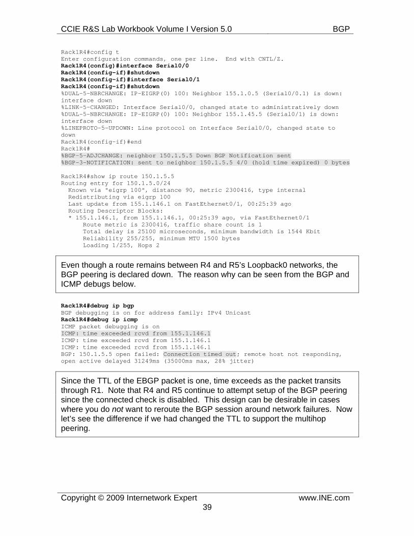
Rack1R4#config t Enter configuration commands, one per line. End with CNTL/Z. Rack1R4(config)#interface Serial0/0 Rack1R4(config-if)#shutdown Rack1R4(config-if)#interface Serial0/1 Rack1R4(config-if)#shutdown %DUAL-5-NBRCHANGE: IP-EIGRP(0) 100: Neighbor 155.1.0.5 (Serial0/0.1) is down: interface down %LINK-5-CHANGED: Interface Serial0/0, changed state to administratively down %DUAL-5-NBRCHANGE: IP-EIGRP(0) 100: Neighbor 155.1.45.5 (Serial0/1) is down: interface down %LINEPROTO-5-UPDOWN: Line protocol on Interface Serial0/0, changed state to down Rack1R4(config-if)#end Rack1R4# %BGP-5-ADJCHANGE: neighbor 150.1.5.5 Down BGP Notification sent %BGP-3-NOTIFICATION: sent to neighbor 150.1.5.5 4/0 (hold time expired) 0 bytes
Rack1R4#show ip route 150.1.5.5 Routing entry for 150.1.5.0/24 Known via "eigrp 100", distance 90, metric 2300416, type internal Redistributing via eigrp 100 Last update from 155.1.146.1 on FastEthernet0/1, 00:25:39 ago Routing Descriptor Blocks: * 155.1.146.1, from 155.1.146.1, 00:25:39 ago, via FastEthernet0/1 Route metric is 2300416, traffic share count is 1 Total delay is 25100 microseconds, minimum bandwidth is 1544 Kbit Reliability 255/255, minimum MTU 1500 bytes Loading 1/255, Hops 2
Even though a route remains between R4 and R5’s Loopback0 networks, the BGP peering is declared down. The reason why can be seen from the BGP and ICMP debugs below.
Rack1R4#debug ip bgp BGP debugging is on for address family: IPv4 Unicast Rack1R4#debug ip icmp ICMP packet debugging is on ICMP: time exceeded rcvd from 155.1.146.1 ICMP: time exceeded rcvd from 155.1.146.1 ICMP: time exceeded rcvd from 155.1.146.1 BGP: 150.1.5.5 open failed: Connection timed out; remote host not responding, open active delayed 31249ms (35000ms max, 28% jitter)
Since the TTL of the EBGP packet is one, time exceeds as the packet transits through R1. Note that R4 and R5 continue to attempt setup of the BGP peering since the connected check is disabled. This design can be desirable in cases where you do not want to reroute the BGP session around network failures. Now let’s see the difference if we had changed the TTL to support the multihop peering.
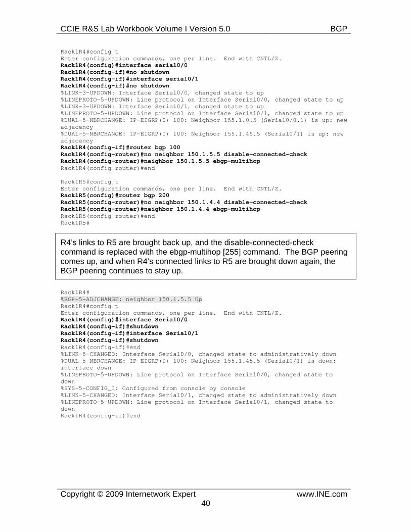
CCIE R&S Lab Workbook Volume I Version 5.0 BGP
Copyright © 2009 Internetwork Expert www.INE.com40
Rack1R4#config t Enter configuration commands, one per line. End with CNTL/Z. Rack1R4(config)#interface serial0/0 Rack1R4(config-if)#no shutdown Rack1R4(config-if)#interface serial0/1 Rack1R4(config-if)#no shutdown %LINK-3-UPDOWN: Interface Serial0/0, changed state to up %LINEPROTO-5-UPDOWN: Line protocol on Interface Serial0/0, changed state to up %LINK-3-UPDOWN: Interface Serial0/1, changed state to up %LINEPROTO-5-UPDOWN: Line protocol on Interface Serial0/1, changed state to up %DUAL-5-NBRCHANGE: IP-EIGRP(0) 100: Neighbor 155.1.0.5 (Serial0/0.1) is up: new adjacency %DUAL-5-NBRCHANGE: IP-EIGRP(0) 100: Neighbor 155.1.45.5 (Serial0/1) is up: new adjacency Rack1R4(config-if)#router bgp 100 Rack1R4(config-router)#no neighbor 150.1.5.5 disable-connected-check Rack1R4(config-router)#neighbor 150.1.5.5 ebgp-multihop Rack1R4(config-router)#end
Rack1R5#config t Enter configuration commands, one per line. End with CNTL/Z. Rack1R5(config)#router bgp 200 Rack1R5(config-router)#no neighbor 150.1.4.4 disable-connected-check Rack1R5(config-router)#neighbor 150.1.4.4 ebgp-multihop Rack1R5(config-router)#end Rack1R5#
R4’s links to R5 are brought back up, and the disable-connected-check command is replaced with the ebgp-multihop [255] command. The BGP peering comes up, and when R4’s connected links to R5 are brought down again, the BGP peering continues to stay up.
Rack1R4# %BGP-5-ADJCHANGE: neighbor 150.1.5.5 Up Rack1R4#config t Enter configuration commands, one per line. End with CNTL/Z. Rack1R4(config)#interface Serial0/0 Rack1R4(config-if)#shutdown Rack1R4(config-if)#interface Serial0/1 Rack1R4(config-if)#shutdown Rack1R4(config-if)#end %LINK-5-CHANGED: Interface Serial0/0, changed state to administratively down %DUAL-5-NBRCHANGE: IP-EIGRP(0) 100: Neighbor 155.1.45.5 (Serial0/1) is down: interface down %LINEPROTO-5-UPDOWN: Line protocol on Interface Serial0/0, changed state to down %SYS-5-CONFIG_I: Configured from console by console %LINK-5-CHANGED: Interface Serial0/1, changed state to administratively down %LINEPROTO-5-UPDOWN: Line protocol on Interface Serial0/1, changed state to down Rack1R4(config-if)#end
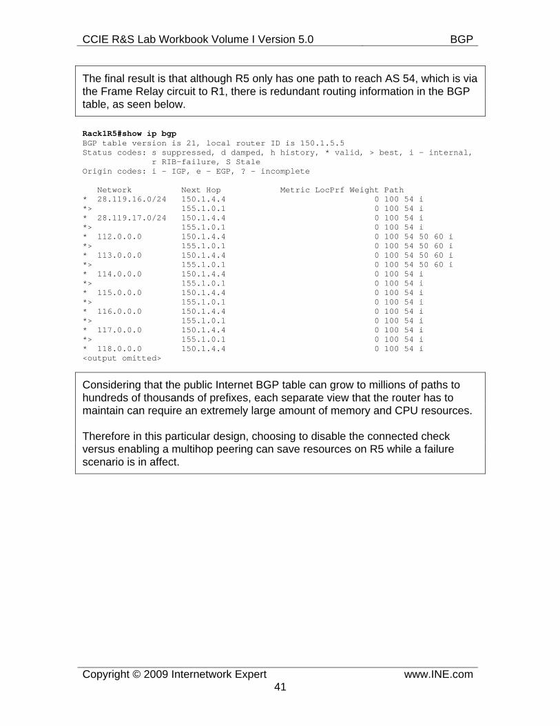
CCIE R&S Lab Workbook Volume I Version 5.0 BGP
Copyright © 2009 Internetwork Expert www.INE.com41
The final result is that although R5 only has one path to reach AS 54, which is via the Frame Relay circuit to R1, there is redundant routing information in the BGP table, as seen below.
Rack1R5#show ip bgp BGP table version is 21, local router ID is 150.1.5.5 Status codes: s suppressed, d damped, h history, * valid, > best, i - internal, r RIB-failure, S Stale Origin codes: i - IGP, e - EGP, ? - incomplete
Network Next Hop Metric LocPrf Weight Path * 28.119.16.0/24 150.1.4.4 0 100 54 i *> 155.1.0.1 0 100 54 i * 28.119.17.0/24 150.1.4.4 0 100 54 i *> 155.1.0.1 0 100 54 i * 112.0.0.0 150.1.4.4 0 100 54 50 60 i *> 155.1.0.1 0 100 54 50 60 i * 113.0.0.0 150.1.4.4 0 100 54 50 60 i *> 155.1.0.1 0 100 54 50 60 i * 114.0.0.0 150.1.4.4 0 100 54 i *> 155.1.0.1 0 100 54 i * 115.0.0.0 150.1.4.4 0 100 54 i *> 155.1.0.1 0 100 54 i * 116.0.0.0 150.1.4.4 0 100 54 i *> 155.1.0.1 0 100 54 i * 117.0.0.0 150.1.4.4 0 100 54 i *> 155.1.0.1 0 100 54 i * 118.0.0.0 150.1.4.4 0 100 54 i <output omitted>
Considering that the public Internet BGP table can grow to millions of paths to hundreds of thousands of prefixes, each separate view that the router has to maintain can require an extremely large amount of memory and CPU resources.
Therefore in this particular design, choosing to disable the connected check versus enabling a multihop peering can save resources on R5 while a failure scenario is in affect.
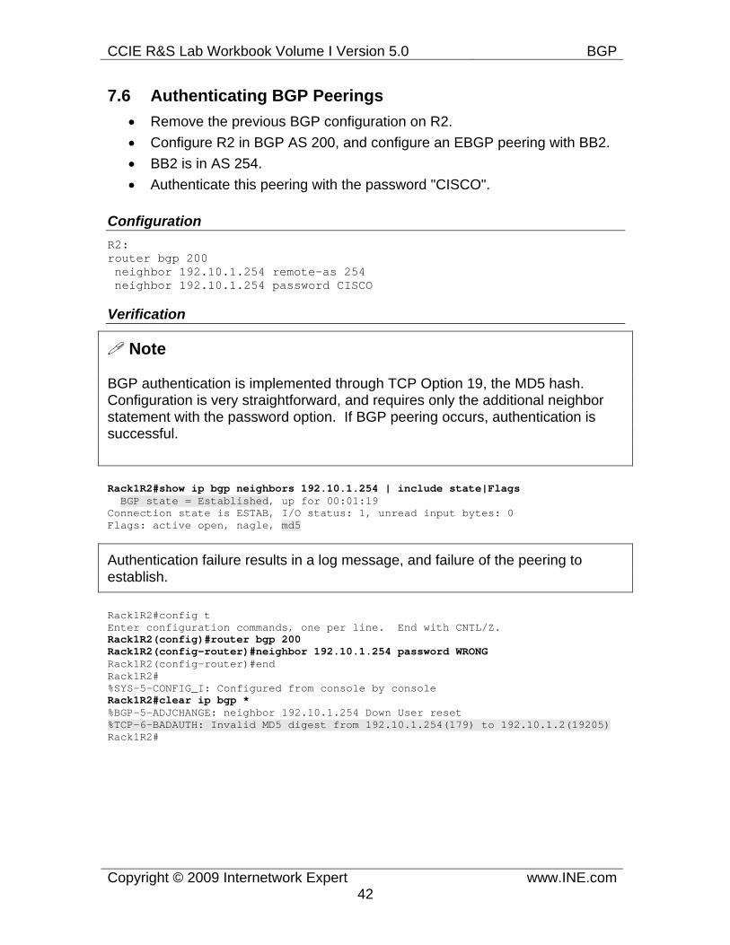
CCIE R&S Lab Workbook Volume I Version 5.0 BGP
Copyright © 2009 Internetwork Expert www.INE.com42
7.6 Authenticating BGP Peerings • Remove the previous BGP configuration on R2. • Configure R2 in BGP AS 200, and configure an EBGP peering with BB2. • BB2 is in AS 254. • Authenticate this peering with the password "CISCO".
Configuration R2: router bgp 200 neighbor 192.10.1.254 remote-as 254 neighbor 192.10.1.254 password CISCO
Verification
Note
BGP authentication is implemented through TCP Option 19, the MD5 hash. Configuration is very straightforward, and requires only the additional neighbor statement with the password option. If BGP peering occurs, authentication is successful.
Rack1R2#show ip bgp neighbors 192.10.1.254 | include state|Flags BGP state = Established, up for 00:01:19 Connection state is ESTAB, I/O status: 1, unread input bytes: 0 Flags: active open, nagle, md5
Authentication failure results in a log message, and failure of the peering to establish.
Rack1R2#config t Enter configuration commands, one per line. End with CNTL/Z. Rack1R2(config)#router bgp 200 Rack1R2(config-router)#neighbor 192.10.1.254 password WRONG Rack1R2(config-router)#end Rack1R2# %SYS-5-CONFIG_I: Configured from console by console Rack1R2#clear ip bgp * %BGP-5-ADJCHANGE: neighbor 192.10.1.254 Down User reset %TCP-6-BADAUTH: Invalid MD5 digest from 192.10.1.254(179) to 192.10.1.2(19205) Rack1R2#
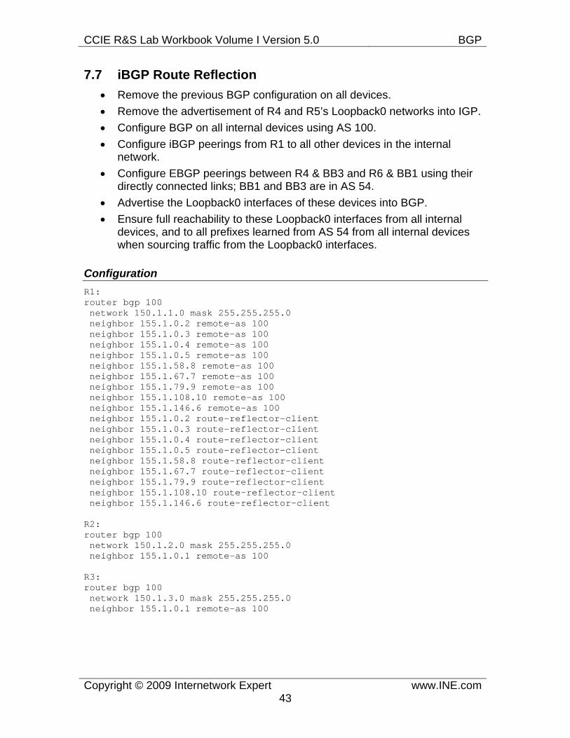
CCIE R&S Lab Workbook Volume I Version 5.0 BGP
Copyright © 2009 Internetwork Expert www.INE.com43
7.7 iBGP Route Reflection • Remove the previous BGP configuration on all devices. • Remove the advertisement of R4 and R5’s Loopback0 networks into IGP. • Configure BGP on all internal devices using AS 100. • Configure iBGP peerings from R1 to all other devices in the internal
network. • Configure EBGP peerings between R4 & BB3 and R6 & BB1 using their
directly connected links; BB1 and BB3 are in AS 54. • Advertise the Loopback0 interfaces of these devices into BGP. • Ensure full reachability to these Loopback0 interfaces from all internal
devices, and to all prefixes learned from AS 54 from all internal devices when sourcing traffic from the Loopback0 interfaces.
Configuration R1: router bgp 100 network 150.1.1.0 mask 255.255.255.0 neighbor 155.1.0.2 remote-as 100 neighbor 155.1.0.3 remote-as 100 neighbor 155.1.0.4 remote-as 100 neighbor 155.1.0.5 remote-as 100 neighbor 155.1.58.8 remote-as 100 neighbor 155.1.67.7 remote-as 100 neighbor 155.1.79.9 remote-as 100 neighbor 155.1.108.10 remote-as 100 neighbor 155.1.146.6 remote-as 100 neighbor 155.1.0.2 route-reflector-client neighbor 155.1.0.3 route-reflector-client neighbor 155.1.0.4 route-reflector-client neighbor 155.1.0.5 route-reflector-client neighbor 155.1.58.8 route-reflector-client neighbor 155.1.67.7 route-reflector-client neighbor 155.1.79.9 route-reflector-client neighbor 155.1.108.10 route-reflector-client neighbor 155.1.146.6 route-reflector-client
R2: router bgp 100 network 150.1.2.0 mask 255.255.255.0 neighbor 155.1.0.1 remote-as 100
R3: router bgp 100 network 150.1.3.0 mask 255.255.255.0 neighbor 155.1.0.1 remote-as 100
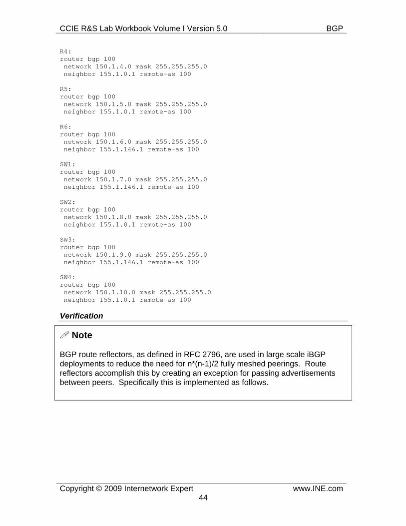
CCIE R&S Lab Workbook Volume I Version 5.0 BGP
Copyright © 2009 Internetwork Expert www.INE.com44
R4: router bgp 100 network 150.1.4.0 mask 255.255.255.0 neighbor 155.1.0.1 remote-as 100
R5: router bgp 100 network 150.1.5.0 mask 255.255.255.0 neighbor 155.1.0.1 remote-as 100 R6: router bgp 100 network 150.1.6.0 mask 255.255.255.0 neighbor 155.1.146.1 remote-as 100
SW1: router bgp 100 network 150.1.7.0 mask 255.255.255.0 neighbor 155.1.146.1 remote-as 100
SW2: router bgp 100 network 150.1.8.0 mask 255.255.255.0 neighbor 155.1.0.1 remote-as 100 SW3: router bgp 100 network 150.1.9.0 mask 255.255.255.0 neighbor 155.1.146.1 remote-as 100
SW4: router bgp 100 network 150.1.10.0 mask 255.255.255.0 neighbor 155.1.0.1 remote-as 100
Verification
Note
BGP route reflectors, as defined in RFC 2796, are used in large scale iBGP deployments to reduce the need for n*(n-1)/2 fully meshed peerings. Route reflectors accomplish this by creating an exception for passing advertisements between peers. Specifically this is implemented as follows.
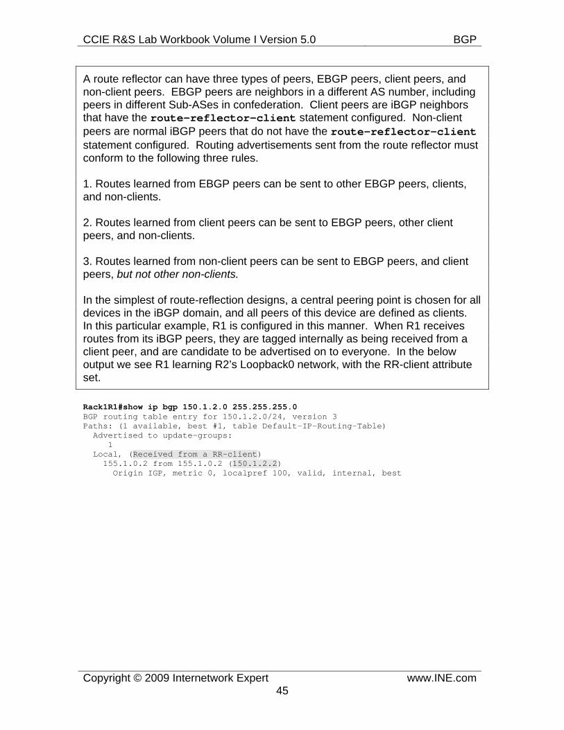
CCIE R&S Lab Workbook Volume I Version 5.0 BGP
Copyright © 2009 Internetwork Expert www.INE.com45
A route reflector can have three types of peers, EBGP peers, client peers, and non-client peers. EBGP peers are neighbors in a different AS number, including peers in different Sub-ASes in confederation. Client peers are iBGP neighbors that have the route-reflector-client statement configured. Non-client peers are normal iBGP peers that do not have the route-reflector-client statement configured. Routing advertisements sent from the route reflector must conform to the following three rules.
1. Routes learned from EBGP peers can be sent to other EBGP peers, clients, and non-clients.
2. Routes learned from client peers can be sent to EBGP peers, other client peers, and non-clients.
3. Routes learned from non-client peers can be sent to EBGP peers, and client peers, but not other non-clients.
In the simplest of route-reflection designs, a central peering point is chosen for all devices in the iBGP domain, and all peers of this device are defined as clients. In this particular example, R1 is configured in this manner. When R1 receives routes from its iBGP peers, they are tagged internally as being received from a client peer, and are candidate to be advertised on to everyone. In the below output we see R1 learning R2’s Loopback0 network, with the RR-client attribute set.
Rack1R1#show ip bgp 150.1.2.0 255.255.255.0 BGP routing table entry for 150.1.2.0/24, version 3 Paths: (1 available, best #1, table Default-IP-Routing-Table) Advertised to update-groups: 1 Local, (Received from a RR-client) 155.1.0.2 from 155.1.0.2 (150.1.2.2) Origin IGP, metric 0, localpref 100, valid, internal, best
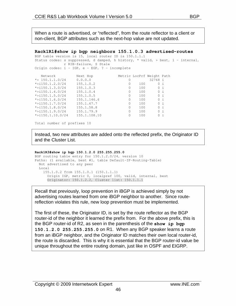
CCIE R&S Lab Workbook Volume I Version 5.0 BGP
Copyright © 2009 Internetwork Expert www.INE.com46
When a route is advertised, or “reflected”, from the route reflector to a client or non-client, BGP attributes such as the next-hop value are not updated.
Rack1R1#show ip bgp neighbors 155.1.0.3 advertised-routes BGP table version is 15, local router ID is 150.1.1.1 Status codes: s suppressed, d damped, h history, * valid, > best, i - internal, r RIB-failure, S Stale Origin codes: i - IGP, e - EGP, ? - incomplete
Network Next Hop Metric LocPrf Weight Path *> 150.1.1.0/24 0.0.0.0 0 32768 i *>i150.1.2.0/24 155.1.0.2 0 100 0 i *>i150.1.3.0/24 155.1.0.3 0 100 0 i *>i150.1.4.0/24 155.1.0.4 0 100 0 i *>i150.1.5.0/24 155.1.0.5 0 100 0 i *>i150.1.6.0/24 155.1.146.6 0 100 0 i *>i150.1.7.0/24 155.1.67.7 0 100 0 i *>i150.1.8.0/24 155.1.58.8 0 100 0 i *>i150.1.9.0/24 155.1.79.9 0 100 0 i *>i150.1.10.0/24 155.1.108.10 0 100 0 i
Total number of prefixes 10
Instead, two new attributes are added onto the reflected prefix, the Originator ID and the Cluster List.
Rack1R3#show ip bgp 150.1.2.0 255.255.255.0 BGP routing table entry for 150.1.2.0/24, version 10 Paths: (1 available, best #1, table Default-IP-Routing-Table) Not advertised to any peer Local 155.1.0.2 from 155.1.0.1 (150.1.1.1) Origin IGP, metric 0, localpref 100, valid, internal, best Originator: 150.1.2.2, Cluster list: 150.1.1.1
Recall that previously, loop prevention in iBGP is achieved simply by not advertising routes learned from one iBGP neighbor to another. Since route-reflection violates this rule, new loop prevention must be implemented.
The first of these, the Originator ID, is set by the route reflector as the BGP router-id of the neighbor it learned the prefix from. For the above prefix, this is the BGP router-id of R2, as seen in the parenthesis of the show ip bgp 150.1.2.0 255.255.255.0 on R1. When any BGP speaker learns a route from an iBGP neighbor, and the Originator ID matches their own local router-id, the route is discarded. This is why it is essential that the BGP router-id value be unique throughout the entire routing domain, just like in OSPF and EIGRP.
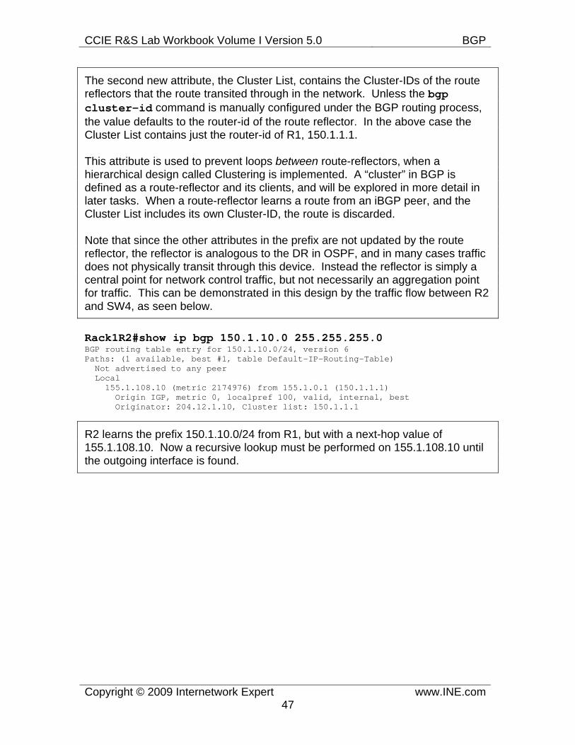
CCIE R&S Lab Workbook Volume I Version 5.0 BGP
Copyright © 2009 Internetwork Expert www.INE.com47
The second new attribute, the Cluster List, contains the Cluster-IDs of the route reflectors that the route transited through in the network. Unless the bgp cluster-id command is manually configured under the BGP routing process, the value defaults to the router-id of the route reflector. In the above case the Cluster List contains just the router-id of R1, 150.1.1.1.
This attribute is used to prevent loops between route-reflectors, when a hierarchical design called Clustering is implemented. A “cluster” in BGP is defined as a route-reflector and its clients, and will be explored in more detail in later tasks. When a route-reflector learns a route from an iBGP peer, and the Cluster List includes its own Cluster-ID, the route is discarded.
Note that since the other attributes in the prefix are not updated by the route reflector, the reflector is analogous to the DR in OSPF, and in many cases traffic does not physically transit through this device. Instead the reflector is simply a central point for network control traffic, but not necessarily an aggregation point for traffic. This can be demonstrated in this design by the traffic flow between R2 and SW4, as seen below.
Rack1R2#show ip bgp 150.1.10.0 255.255.255.0 BGP routing table entry for 150.1.10.0/24, version 6 Paths: (1 available, best #1, table Default-IP-Routing-Table) Not advertised to any peer Local 155.1.108.10 (metric 2174976) from 155.1.0.1 (150.1.1.1) Origin IGP, metric 0, localpref 100, valid, internal, best Originator: 204.12.1.10, Cluster list: 150.1.1.1
R2 learns the prefix 150.1.10.0/24 from R1, but with a next-hop value of 155.1.108.10. Now a recursive lookup must be performed on 155.1.108.10 until the outgoing interface is found.
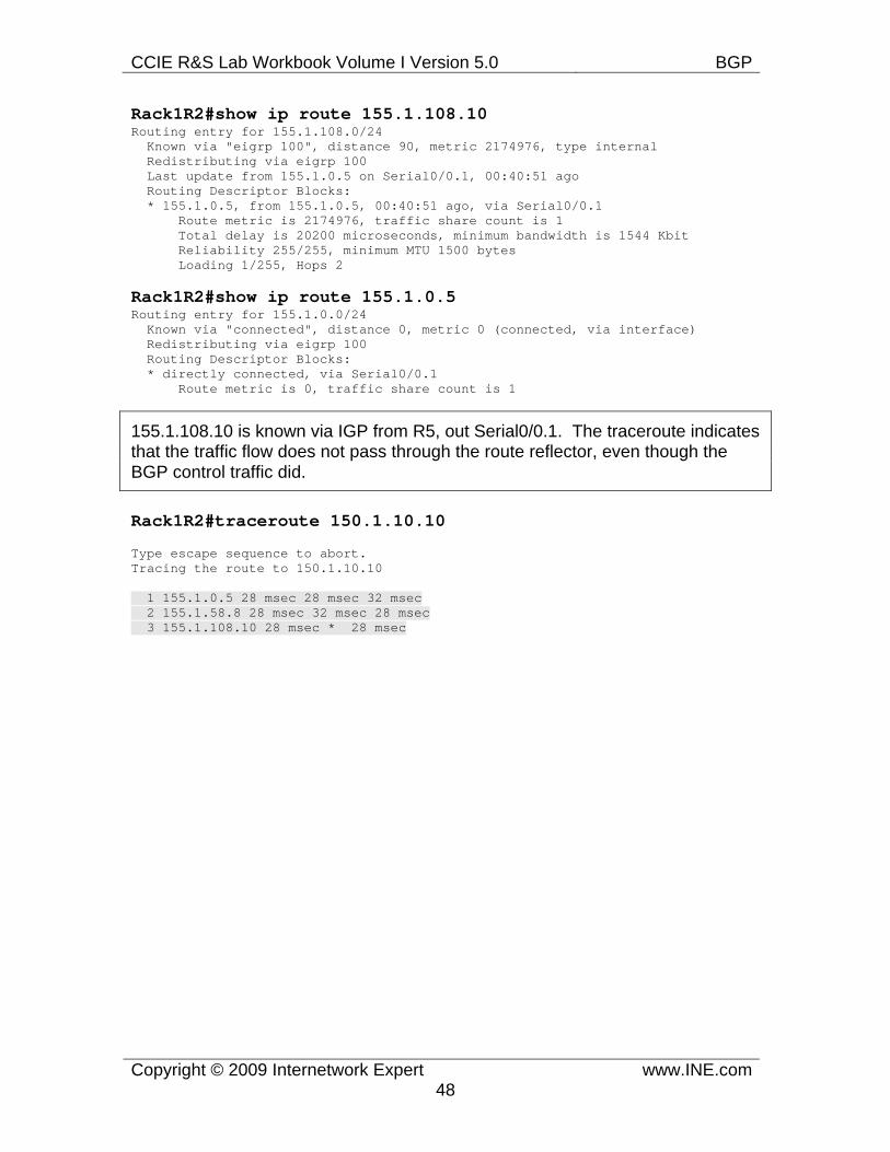
CCIE R&S Lab Workbook Volume I Version 5.0 BGP
Copyright © 2009 Internetwork Expert www.INE.com48
Rack1R2#show ip route 155.1.108.10 Routing entry for 155.1.108.0/24 Known via "eigrp 100", distance 90, metric 2174976, type internal Redistributing via eigrp 100 Last update from 155.1.0.5 on Serial0/0.1, 00:40:51 ago Routing Descriptor Blocks: * 155.1.0.5, from 155.1.0.5, 00:40:51 ago, via Serial0/0.1 Route metric is 2174976, traffic share count is 1 Total delay is 20200 microseconds, minimum bandwidth is 1544 Kbit Reliability 255/255, minimum MTU 1500 bytes Loading 1/255, Hops 2
Rack1R2#show ip route 155.1.0.5 Routing entry for 155.1.0.0/24 Known via "connected", distance 0, metric 0 (connected, via interface) Redistributing via eigrp 100 Routing Descriptor Blocks: * directly connected, via Serial0/0.1 Route metric is 0, traffic share count is 1
155.1.108.10 is known via IGP from R5, out Serial0/0.1. The traceroute indicates that the traffic flow does not pass through the route reflector, even though the BGP control traffic did.
Rack1R2#traceroute 150.1.10.10
Type escape sequence to abort. Tracing the route to 150.1.10.10
1 155.1.0.5 28 msec 28 msec 32 msec 2 155.1.58.8 28 msec 32 msec 28 msec 3 155.1.108.10 28 msec * 28 msec
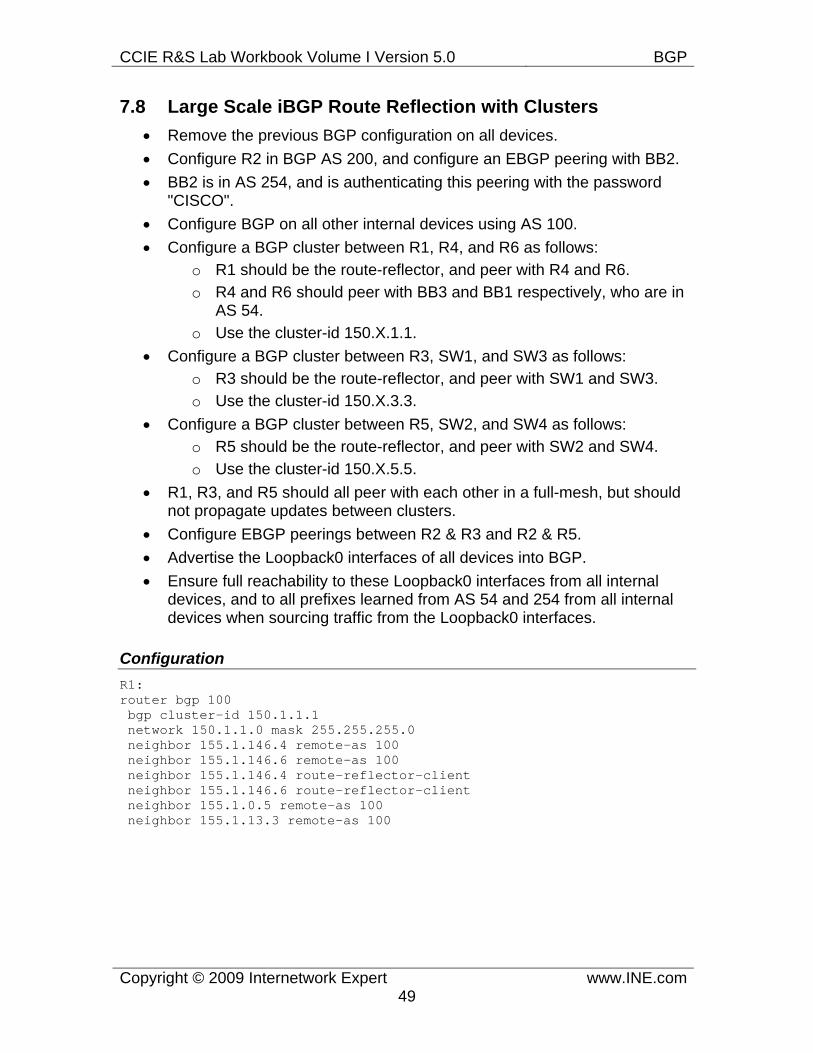
CCIE R&S Lab Workbook Volume I Version 5.0 BGP
Copyright © 2009 Internetwork Expert www.INE.com49
7.8 Large Scale iBGP Route Reflection with Clusters • Remove the previous BGP configuration on all devices. • Configure R2 in BGP AS 200, and configure an EBGP peering with BB2. • BB2 is in AS 254, and is authenticating this peering with the password
"CISCO". • Configure BGP on all other internal devices using AS 100. • Configure a BGP cluster between R1, R4, and R6 as follows:
o R1 should be the route-reflector, and peer with R4 and R6. o R4 and R6 should peer with BB3 and BB1 respectively, who are in
AS 54. o Use the cluster-id 150.X.1.1.
• Configure a BGP cluster between R3, SW1, and SW3 as follows: o R3 should be the route-reflector, and peer with SW1 and SW3. o Use the cluster-id 150.X.3.3.
• Configure a BGP cluster between R5, SW2, and SW4 as follows: o R5 should be the route-reflector, and peer with SW2 and SW4. o Use the cluster-id 150.X.5.5.
• R1, R3, and R5 should all peer with each other in a full-mesh, but should not propagate updates between clusters.
• Configure EBGP peerings between R2 & R3 and R2 & R5. • Advertise the Loopback0 interfaces of all devices into BGP. • Ensure full reachability to these Loopback0 interfaces from all internal
devices, and to all prefixes learned from AS 54 and 254 from all internal devices when sourcing traffic from the Loopback0 interfaces.
Configuration R1: router bgp 100 bgp cluster-id 150.1.1.1 network 150.1.1.0 mask 255.255.255.0 neighbor 155.1.146.4 remote-as 100 neighbor 155.1.146.6 remote-as 100 neighbor 155.1.146.4 route-reflector-client neighbor 155.1.146.6 route-reflector-client neighbor 155.1.0.5 remote-as 100 neighbor 155.1.13.3 remote-as 100
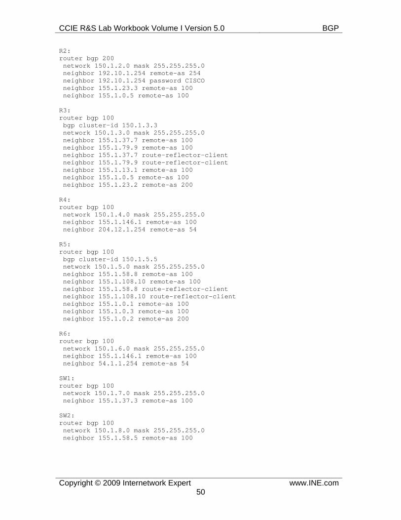
CCIE R&S Lab Workbook Volume I Version 5.0 BGP
Copyright © 2009 Internetwork Expert www.INE.com50
R2: router bgp 200 network 150.1.2.0 mask 255.255.255.0 neighbor 192.10.1.254 remote-as 254 neighbor 192.10.1.254 password CISCO neighbor 155.1.23.3 remote-as 100 neighbor 155.1.0.5 remote-as 100
R3: router bgp 100 bgp cluster-id 150.1.3.3 network 150.1.3.0 mask 255.255.255.0 neighbor 155.1.37.7 remote-as 100 neighbor 155.1.79.9 remote-as 100 neighbor 155.1.37.7 route-reflector-client neighbor 155.1.79.9 route-reflector-client neighbor 155.1.13.1 remote-as 100 neighbor 155.1.0.5 remote-as 100 neighbor 155.1.23.2 remote-as 200
R4: router bgp 100 network 150.1.4.0 mask 255.255.255.0 neighbor 155.1.146.1 remote-as 100 neighbor 204.12.1.254 remote-as 54
R5: router bgp 100 bgp cluster-id 150.1.5.5 network 150.1.5.0 mask 255.255.255.0 neighbor 155.1.58.8 remote-as 100 neighbor 155.1.108.10 remote-as 100 neighbor 155.1.58.8 route-reflector-client neighbor 155.1.108.10 route-reflector-client neighbor 155.1.0.1 remote-as 100 neighbor 155.1.0.3 remote-as 100 neighbor 155.1.0.2 remote-as 200 R6: router bgp 100 network 150.1.6.0 mask 255.255.255.0 neighbor 155.1.146.1 remote-as 100 neighbor 54.1.1.254 remote-as 54
SW1: router bgp 100 network 150.1.7.0 mask 255.255.255.0 neighbor 155.1.37.3 remote-as 100
SW2: router bgp 100 network 150.1.8.0 mask 255.255.255.0 neighbor 155.1.58.5 remote-as 100
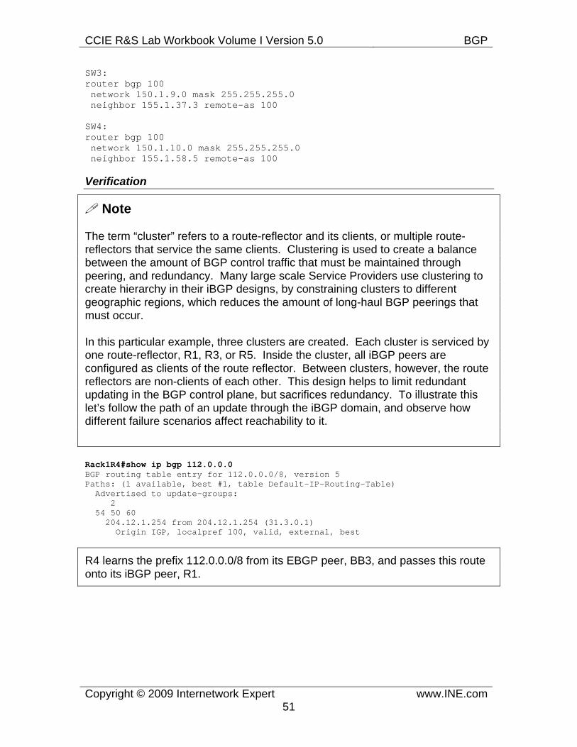
CCIE R&S Lab Workbook Volume I Version 5.0 BGP
Copyright © 2009 Internetwork Expert www.INE.com51
SW3: router bgp 100 network 150.1.9.0 mask 255.255.255.0 neighbor 155.1.37.3 remote-as 100
SW4: router bgp 100 network 150.1.10.0 mask 255.255.255.0 neighbor 155.1.58.5 remote-as 100
Verification
Note
The term “cluster” refers to a route-reflector and its clients, or multiple route-reflectors that service the same clients. Clustering is used to create a balance between the amount of BGP control traffic that must be maintained through peering, and redundancy. Many large scale Service Providers use clustering to create hierarchy in their iBGP designs, by constraining clusters to different geographic regions, which reduces the amount of long-haul BGP peerings that must occur.
In this particular example, three clusters are created. Each cluster is serviced by one route-reflector, R1, R3, or R5. Inside the cluster, all iBGP peers are configured as clients of the route reflector. Between clusters, however, the route reflectors are non-clients of each other. This design helps to limit redundant updating in the BGP control plane, but sacrifices redundancy. To illustrate this let’s follow the path of an update through the iBGP domain, and observe how different failure scenarios affect reachability to it.
Rack1R4#show ip bgp 112.0.0.0 BGP routing table entry for 112.0.0.0/8, version 5 Paths: (1 available, best #1, table Default-IP-Routing-Table) Advertised to update-groups: 2 54 50 60 204.12.1.254 from 204.12.1.254 (31.3.0.1) Origin IGP, localpref 100, valid, external, best
R4 learns the prefix 112.0.0.0/8 from its EBGP peer, BB3, and passes this route onto its iBGP peer, R1.
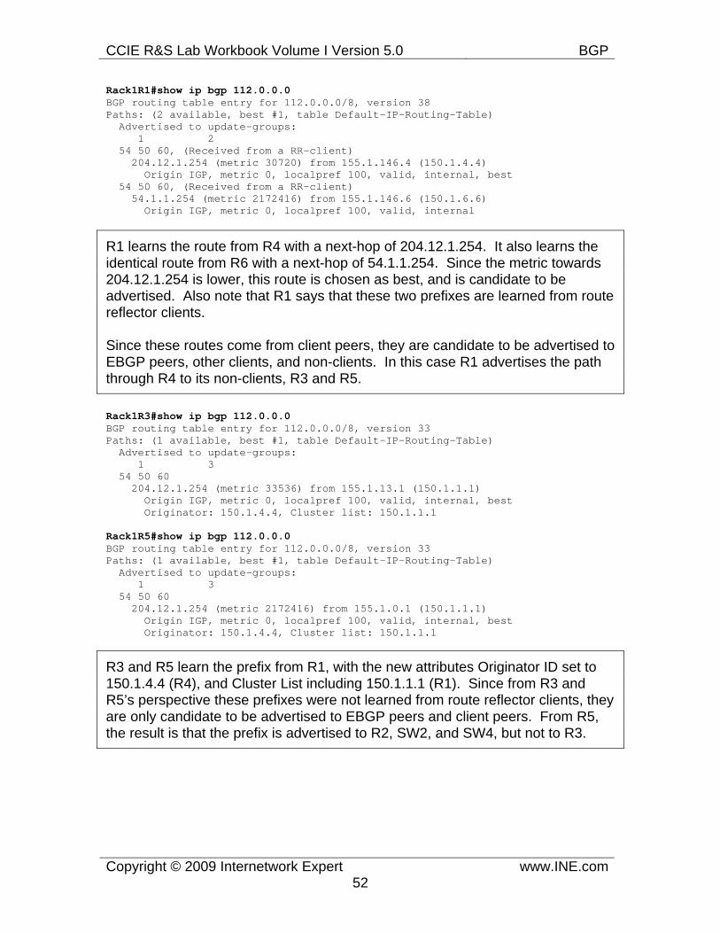
CCIE R&S Lab Workbook Volume I Version 5.0 BGP
Copyright © 2009 Internetwork Expert www.INE.com52
Rack1R1#show ip bgp 112.0.0.0 BGP routing table entry for 112.0.0.0/8, version 38 Paths: (2 available, best #1, table Default-IP-Routing-Table) Advertised to update-groups: 1 2 54 50 60, (Received from a RR-client) 204.12.1.254 (metric 30720) from 155.1.146.4 (150.1.4.4) Origin IGP, metric 0, localpref 100, valid, internal, best 54 50 60, (Received from a RR-client) 54.1.1.254 (metric 2172416) from 155.1.146.6 (150.1.6.6) Origin IGP, metric 0, localpref 100, valid, internal
R1 learns the route from R4 with a next-hop of 204.12.1.254. It also learns the identical route from R6 with a next-hop of 54.1.1.254. Since the metric towards 204.12.1.254 is lower, this route is chosen as best, and is candidate to be advertised. Also note that R1 says that these two prefixes are learned from route reflector clients.
Since these routes come from client peers, they are candidate to be advertised to EBGP peers, other clients, and non-clients. In this case R1 advertises the path through R4 to its non-clients, R3 and R5.
Rack1R3#show ip bgp 112.0.0.0 BGP routing table entry for 112.0.0.0/8, version 33 Paths: (1 available, best #1, table Default-IP-Routing-Table) Advertised to update-groups: 1 3 54 50 60 204.12.1.254 (metric 33536) from 155.1.13.1 (150.1.1.1) Origin IGP, metric 0, localpref 100, valid, internal, best Originator: 150.1.4.4, Cluster list: 150.1.1.1
Rack1R5#show ip bgp 112.0.0.0 BGP routing table entry for 112.0.0.0/8, version 33 Paths: (1 available, best #1, table Default-IP-Routing-Table) Advertised to update-groups: 1 3 54 50 60 204.12.1.254 (metric 2172416) from 155.1.0.1 (150.1.1.1) Origin IGP, metric 0, localpref 100, valid, internal, best Originator: 150.1.4.4, Cluster list: 150.1.1.1
R3 and R5 learn the prefix from R1, with the new attributes Originator ID set to 150.1.4.4 (R4), and Cluster List including 150.1.1.1 (R1). Since from R3 and R5’s perspective these prefixes were not learned from route reflector clients, they are only candidate to be advertised to EBGP peers and client peers. From R5, the result is that the prefix is advertised to R2, SW2, and SW4, but not to R3.
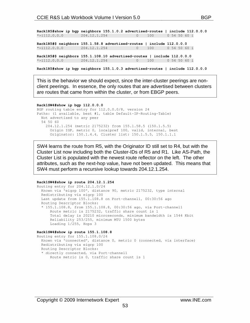
CCIE R&S Lab Workbook Volume I Version 5.0 BGP
Copyright © 2009 Internetwork Expert www.INE.com53
Rack1R5#show ip bgp neighbors 155.1.0.2 advertised-routes | include 112.0.0.0 *>i112.0.0.0 204.12.1.254 0 100 0 54 50 60 i
Rack1R5#$ neighbors 155.1.58.8 advertised-routes | include 112.0.0.0 *>i112.0.0.0 204.12.1.254 0 100 0 54 50 60 i
Rack1R5#$ neighbors 155.1.108.10 advertised-routes | include 112.0.0.0 *>i112.0.0.0 204.12.1.254 0 100 0 54 50 60 i
Rack1R5#show ip bgp neighbors 155.1.0.3 advertised-routes | include 112.0.0.0
This is the behavior we should expect, since the inter-cluster peerings are non-client peerings. In essence, the only routes that are advertised between clusters are routes that came from within the cluster, or from EBGP peers.
Rack1SW4#show ip bgp 112.0.0.0 BGP routing table entry for 112.0.0.0/8, version 24 Paths: (1 available, best #1, table Default-IP-Routing-Table) Not advertised to any peer 54 50 60 204.12.1.254 (metric 2175232) from 155.1.58.5 (150.1.5.5) Origin IGP, metric 0, localpref 100, valid, internal, best Originator: 150.1.4.4, Cluster list: 150.1.5.5, 150.1.1.1
SW4 learns the route from R5, with the Originator ID still set to R4, but with the Cluster List now including both the Cluster-IDs of R5 and R1. Like AS-Path, the Cluster List is populated with the newest route reflector on the left. The other attributes, such as the next-hop value, have not been updated. This means that SW4 must perform a recursive lookup towards 204.12.1.254.
Rack1SW4#show ip route 204.12.1.254 Routing entry for 204.12.1.0/24 Known via "eigrp 100", distance 90, metric 2175232, type internal Redistributing via eigrp 100 Last update from 155.1.108.8 on Port-channel1, 00:30:56 ago Routing Descriptor Blocks: * 155.1.108.8, from 155.1.108.8, 00:30:56 ago, via Port-channel1 Route metric is 2175232, traffic share count is 1 Total delay is 20210 microseconds, minimum bandwidth is 1544 Kbit Reliability 253/255, minimum MTU 1500 bytes Loading 1/255, Hops 3
Rack1SW4#show ip route 155.1.108.8 Routing entry for 155.1.108.0/24 Known via "connected", distance 0, metric 0 (connected, via interface) Redistributing via eigrp 100 Routing Descriptor Blocks: * directly connected, via Port-channel1 Route metric is 0, traffic share count is 1
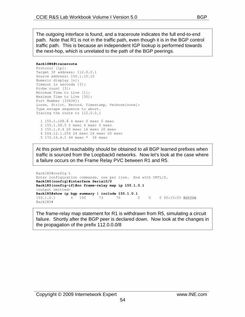
CCIE R&S Lab Workbook Volume I Version 5.0 BGP
Copyright © 2009 Internetwork Expert www.INE.com54
The outgoing interface is found, and a traceroute indicates the full end-to-end path. Note that R1 is not in the traffic path, even though it is in the BGP control traffic path. This is because an independent IGP lookup is performed towards the next-hop, which is unrelated to the path of the BGP peerings.
Rack1SW4#traceroute Protocol [ip]: Target IP address: 112.0.0.1 Source address: 150.1.10.10 Numeric display [n]: Timeout in seconds [3]: Probe count [3]: Minimum Time to Live [1]: Maximum Time to Live [30]: Port Number [33434]: Loose, Strict, Record, Timestamp, Verbose[none]: Type escape sequence to abort. Tracing the route to 112.0.0.1
1 155.1.108.8 4 msec 0 msec 0 msec 2 155.1.58.5 0 msec 4 msec 0 msec 3 155.1.0.4 20 msec 16 msec 20 msec 4 204.12.1.254 24 msec 24 msec 20 msec 5 172.16.4.1 44 msec * 36 msec
At this point full reachability should be obtained to all BGP learned prefixes when traffic is sourced from the Loopback0 networks. Now let’s look at the case where a failure occurs on the Frame Relay PVC between R1 and R5.
Rack1R5#config t Enter configuration commands, one per line. End with CNTL/Z. Rack1R5(config)#interface Serial0/0 Rack1R5(config-if)#no frame-relay map ip 155.1.0.1 <output omitted> Rack1R5#show ip bgp summary | include 155.1.0.1 155.1.0.1 4 100 73 70 0 0 0 00:10:03 Active Rack1R5#
The frame-relay map statement for R1 is withdrawn from R5, simulating a circuit failure. Shortly after the BGP peer is declared down. Now look at the changes in the propagation of the prefix 112.0.0.0/8
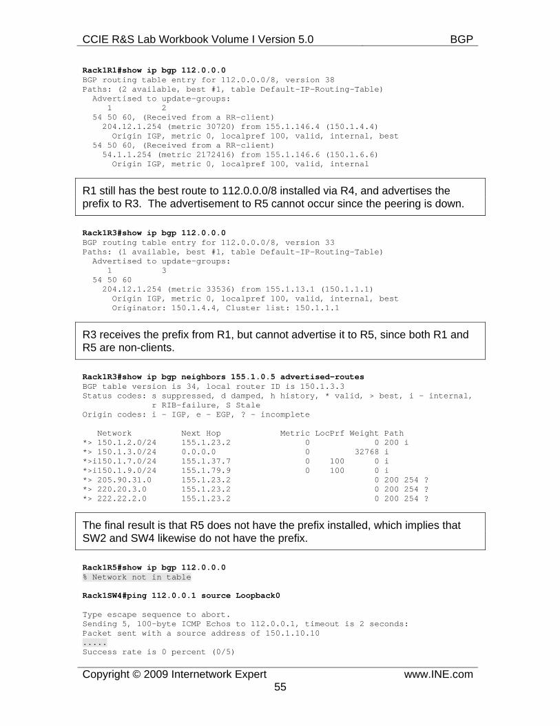
CCIE R&S Lab Workbook Volume I Version 5.0 BGP
Copyright © 2009 Internetwork Expert www.INE.com55
Rack1R1#show ip bgp 112.0.0.0 BGP routing table entry for 112.0.0.0/8, version 38 Paths: (2 available, best #1, table Default-IP-Routing-Table) Advertised to update-groups: 1 2 54 50 60, (Received from a RR-client) 204.12.1.254 (metric 30720) from 155.1.146.4 (150.1.4.4) Origin IGP, metric 0, localpref 100, valid, internal, best 54 50 60, (Received from a RR-client) 54.1.1.254 (metric 2172416) from 155.1.146.6 (150.1.6.6) Origin IGP, metric 0, localpref 100, valid, internal
R1 still has the best route to 112.0.0.0/8 installed via R4, and advertises the prefix to R3. The advertisement to R5 cannot occur since the peering is down.
Rack1R3#show ip bgp 112.0.0.0 BGP routing table entry for 112.0.0.0/8, version 33 Paths: (1 available, best #1, table Default-IP-Routing-Table) Advertised to update-groups: 1 3 54 50 60 204.12.1.254 (metric 33536) from 155.1.13.1 (150.1.1.1) Origin IGP, metric 0, localpref 100, valid, internal, best Originator: 150.1.4.4, Cluster list: 150.1.1.1
R3 receives the prefix from R1, but cannot advertise it to R5, since both R1 and R5 are non-clients.
Rack1R3#show ip bgp neighbors 155.1.0.5 advertised-routes BGP table version is 34, local router ID is 150.1.3.3 Status codes: s suppressed, d damped, h history, * valid, > best, i - internal, r RIB-failure, S Stale Origin codes: i - IGP, e - EGP, ? - incomplete
Network Next Hop Metric LocPrf Weight Path *> 150.1.2.0/24 155.1.23.2 0 0 200 i *> 150.1.3.0/24 0.0.0.0 0 32768 i *>i150.1.7.0/24 155.1.37.7 0 100 0 i *>i150.1.9.0/24 155.1.79.9 0 100 0 i *> 205.90.31.0 155.1.23.2 0 200 254 ? *> 220.20.3.0 155.1.23.2 0 200 254 ? *> 222.22.2.0 155.1.23.2 0 200 254 ?
The final result is that R5 does not have the prefix installed, which implies that SW2 and SW4 likewise do not have the prefix.
Rack1R5#show ip bgp 112.0.0.0 % Network not in table
Rack1SW4#ping 112.0.0.1 source Loopback0
Type escape sequence to abort. Sending 5, 100-byte ICMP Echos to 112.0.0.1, timeout is 2 seconds: Packet sent with a source address of 150.1.10.10 ..... Success rate is 0 percent (0/5)
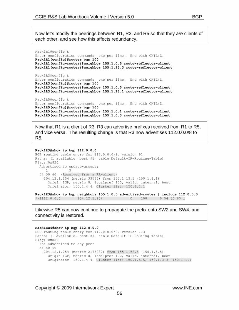
CCIE R&S Lab Workbook Volume I Version 5.0 BGP
Copyright © 2009 Internetwork Expert www.INE.com56
Now let’s modify the peerings between R1, R3, and R5 so that they are clients of each other, and see how this affects redundancy.
Rack1R1#config t Enter configuration commands, one per line. End with CNTL/Z. Rack1R1(config)#router bgp 100 Rack1R1(config-router)#neighbor 155.1.0.5 route-reflector-client Rack1R1(config-router)#neighbor 155.1.13.3 route-reflector-client
Rack1R3#config t Enter configuration commands, one per line. End with CNTL/Z. Rack1R3(config)#router bgp 100 Rack1R3(config-router)#neighbor 155.1.0.5 route-reflector-client Rack1R3(config-router)#neighbor 155.1.13.1 route-reflector-client
Rack1R5#config t Enter configuration commands, one per line. End with CNTL/Z. Rack1R5(config)#router bgp 100 Rack1R5(config-router)#neighbor 155.1.0.1 route-reflector-client Rack1R5(config-router)#neighbor 155.1.0.3 route-reflector-client
Now that R1 is a client of R3, R3 can advertise prefixes received from R1 to R5, and vice versa. The resulting change is that R3 now advertises 112.0.0.0/8 to R5.
Rack1R3#show ip bgp 112.0.0.0 BGP routing table entry for 112.0.0.0/8, version 91 Paths: (1 available, best #1, table Default-IP-Routing-Table) Flag: 0x820 Advertised to update-groups: 1 3 54 50 60, (Received from a RR-client) 204.12.1.254 (metric 33536) from 155.1.13.1 (150.1.1.1) Origin IGP, metric 0, localpref 100, valid, internal, best Originator: 150.1.4.4, Cluster list: 150.1.1.1
Rack1R3#show ip bgp neighbors 155.1.0.5 advertised-routes | include 112.0.0.0 *>i112.0.0.0 204.12.1.254 0 100 0 54 50 60 i
Likewise R5 can now continue to propagate the prefix onto SW2 and SW4, and connectivity is restored.
Rack1SW4#show ip bgp 112.0.0.0 BGP routing table entry for 112.0.0.0/8, version 113 Paths: (1 available, best #1, table Default-IP-Routing-Table) Flag: 0x820 Not advertised to any peer 54 50 60 204.12.1.254 (metric 2175232) from 155.1.58.5 (150.1.5.5) Origin IGP, metric 0, localpref 100, valid, internal, best Originator: 150.1.4.4, Cluster list: 150.1.5.5, 150.1.3.3, 150.1.1.1
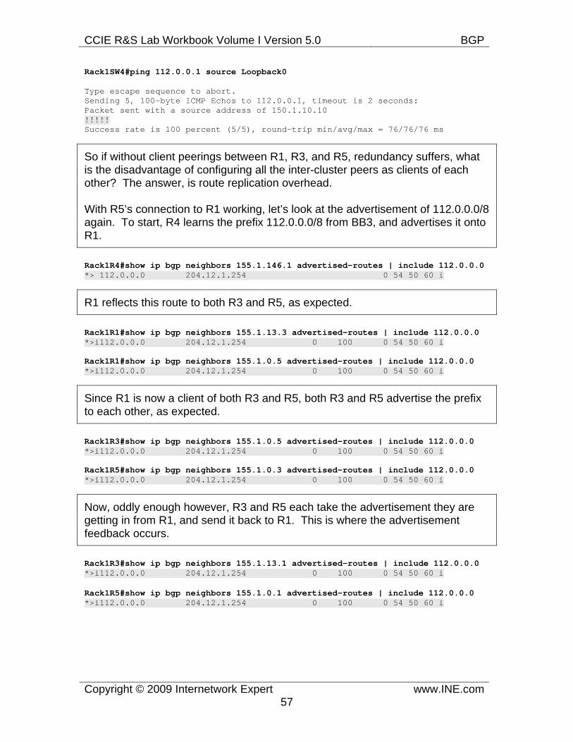
CCIE R&S Lab Workbook Volume I Version 5.0 BGP
Copyright © 2009 Internetwork Expert www.INE.com57
Rack1SW4#ping 112.0.0.1 source Loopback0
Type escape sequence to abort. Sending 5, 100-byte ICMP Echos to 112.0.0.1, timeout is 2 seconds: Packet sent with a source address of 150.1.10.10 !!!!! Success rate is 100 percent (5/5), round-trip min/avg/max = 76/76/76 ms
So if without client peerings between R1, R3, and R5, redundancy suffers, what is the disadvantage of configuring all the inter-cluster peers as clients of each other? The answer, is route replication overhead.
With R5’s connection to R1 working, let’s look at the advertisement of 112.0.0.0/8 again. To start, R4 learns the prefix 112.0.0.0/8 from BB3, and advertises it onto R1.
Rack1R4#show ip bgp neighbors 155.1.146.1 advertised-routes | include 112.0.0.0 *> 112.0.0.0 204.12.1.254 0 54 50 60 i
R1 reflects this route to both R3 and R5, as expected.
Rack1R1#show ip bgp neighbors 155.1.13.3 advertised-routes | include 112.0.0.0 *>i112.0.0.0 204.12.1.254 0 100 0 54 50 60 i
Rack1R1#show ip bgp neighbors 155.1.0.5 advertised-routes | include 112.0.0.0 *>i112.0.0.0 204.12.1.254 0 100 0 54 50 60 i
Since R1 is now a client of both R3 and R5, both R3 and R5 advertise the prefix to each other, as expected.
Rack1R3#show ip bgp neighbors 155.1.0.5 advertised-routes | include 112.0.0.0 *>i112.0.0.0 204.12.1.254 0 100 0 54 50 60 i
Rack1R5#show ip bgp neighbors 155.1.0.3 advertised-routes | include 112.0.0.0 *>i112.0.0.0 204.12.1.254 0 100 0 54 50 60 i
Now, oddly enough however, R3 and R5 each take the advertisement they are getting in from R1, and send it back to R1. This is where the advertisement feedback occurs.
Rack1R3#show ip bgp neighbors 155.1.13.1 advertised-routes | include 112.0.0.0 *>i112.0.0.0 204.12.1.254 0 100 0 54 50 60 i
Rack1R5#show ip bgp neighbors 155.1.0.1 advertised-routes | include 112.0.0.0 *>i112.0.0.0 204.12.1.254 0 100 0 54 50 60 i
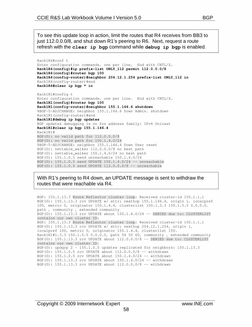
CCIE R&S Lab Workbook Volume I Version 5.0 BGP
Copyright © 2009 Internetwork Expert www.INE.com58
To see this update loop in action, limit the routes that R4 receives from BB3 to just 112.0.0.0/8, and shut down R1’s peering to R6. Next, request a route refresh with the clear ip bgp command while debug ip bgp is enabled.
Rack1R4#conf t Enter configuration commands, one per line. End with CNTL/Z. Rack1R4(config)#ip prefix-list ONLY_112 permit 112.0.0.0/8 Rack1R4(config)#router bgp 100 Rack1R4(config-router)#neighbor 204.12.1.254 prefix-list ONLY_112 in Rack1R4(config-router)#end Rack1R4#clear ip bgp * in
Rack1R1#config t Enter configuration commands, one per line. End with CNTL/Z. Rack1R1(config)#router bgp 100 Rack1R1(config-router)#neighbor 155.1.146.6 shutdown %BGP-5-ADJCHANGE: neighbor 155.1.146.6 Down Admin. shutdown Rack1R1(config-router)#end Rack1R1#debug ip bgp updates BGP updates debugging is on for address family: IPv4 Unicast Rack1R1#clear ip bgp 155.1.146.4 Rack1R1# BGP(0): no valid path for 112.0.0.0/8 BGP(0): no valid path for 150.1.4.0/24 %BGP-5-ADJCHANGE: neighbor 155.1.146.4 Down User reset BGP(0): nettable_walker 112.0.0.0/8 no best path BGP(0): nettable_walker 150.1.4.0/24 no best path BGP(0): 155.1.0.5 send unreachable 150.1.4.0/24 BGP(0): 155.1.0.5 send UPDATE 150.1.4.0/24 -- unreachable BGP(0): 155.1.0.5 send UPDATE 112.0.0.0/8 -- unreachable
With R1’s peering to R4 down, an UPDATE message is sent to withdraw the routes that were reachable via R4.
BGP: 155.1.13.3 Route Reflector cluster loop; Received cluster-id 150.1.1.1 BGP(0): 155.1.13.3 rcv UPDATE w/ attr: nexthop 155.1.146.4, origin i, localpref 100, metric 0, originator 150.1.4.4, clusterlist 150.1.3.3 150.1.5.5 0.0.0.0, path , community , extended community BGP(0): 155.1.13.3 rcv UPDATE about 150.1.4.0/24 -- DENIED due to: CLUSTERLIST contains our own cluster ID; BGP: 155.1.13.3 Route Reflector cluster loop; Received cluster-id 150.1.1.1 BGP(0): 155.1.13.3 rcv UPDATE w/ attr: nexthop 204.12.1.254, origin i, localpref 100, metric 0, originator 150.1.4.4, clusterlist 150. Rack1R1#1.3.3 150.1.5.5 0.0.0.0, path 54 50 60, community , extended community BGP(0): 155.1.13.3 rcv UPDATE about 112.0.0.0/8 -- DENIED due to: CLUSTERLIST contains our own cluster ID; BGP(0): updgrp 2 - 155.1.0.5 updates replicated for neighbors: 155.1.13.3 BGP(0): 155.1.0.5 rcv UPDATE about 112.0.0.0/8 -- withdrawn BGP(0): 155.1.0.5 rcv UPDATE about 150.1.4.0/24 -- withdrawn BGP(0): 155.1.13.3 rcv UPDATE about 150.1.4.0/24 -- withdrawn BGP(0): 155.1.13.3 rcv UPDATE about 112.0.0.0/8 -- withdrawn
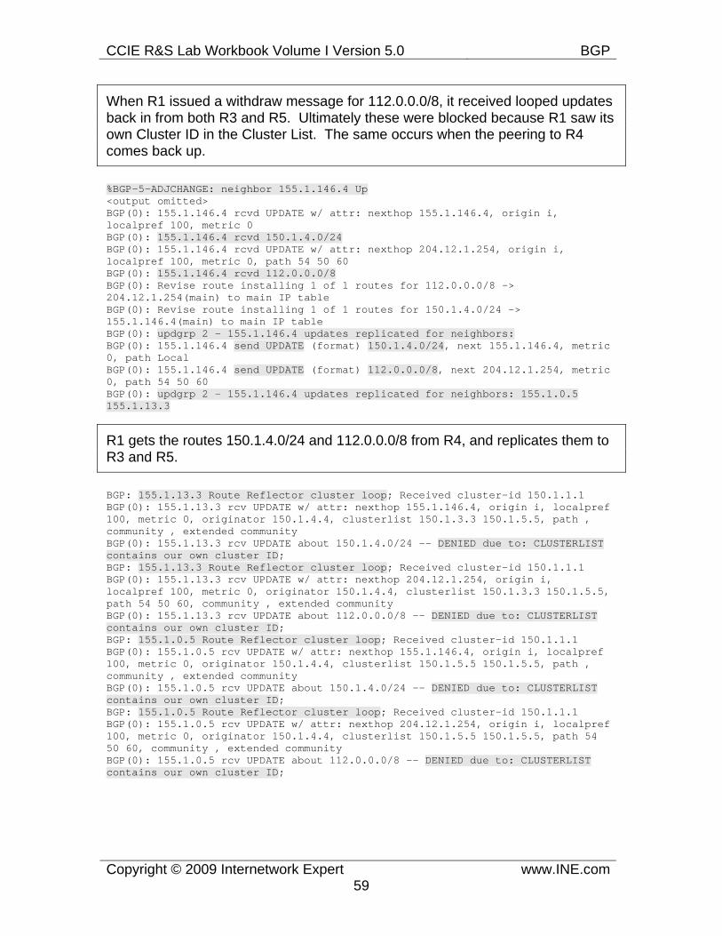
CCIE R&S Lab Workbook Volume I Version 5.0 BGP
Copyright © 2009 Internetwork Expert www.INE.com59
When R1 issued a withdraw message for 112.0.0.0/8, it received looped updates back in from both R3 and R5. Ultimately these were blocked because R1 saw its own Cluster ID in the Cluster List. The same occurs when the peering to R4 comes back up.
%BGP-5-ADJCHANGE: neighbor 155.1.146.4 Up <output omitted> BGP(0): 155.1.146.4 rcvd UPDATE w/ attr: nexthop 155.1.146.4, origin i, localpref 100, metric 0 BGP(0): 155.1.146.4 rcvd 150.1.4.0/24 BGP(0): 155.1.146.4 rcvd UPDATE w/ attr: nexthop 204.12.1.254, origin i, localpref 100, metric 0, path 54 50 60 BGP(0): 155.1.146.4 rcvd 112.0.0.0/8 BGP(0): Revise route installing 1 of 1 routes for 112.0.0.0/8 -> 204.12.1.254(main) to main IP table BGP(0): Revise route installing 1 of 1 routes for 150.1.4.0/24 -> 155.1.146.4(main) to main IP table BGP(0): updgrp 2 - 155.1.146.4 updates replicated for neighbors: BGP(0): 155.1.146.4 send UPDATE (format) 150.1.4.0/24, next 155.1.146.4, metric 0, path Local BGP(0): 155.1.146.4 send UPDATE (format) 112.0.0.0/8, next 204.12.1.254, metric 0, path 54 50 60 BGP(0): updgrp 2 - 155.1.146.4 updates replicated for neighbors: 155.1.0.5 155.1.13.3
R1 gets the routes 150.1.4.0/24 and 112.0.0.0/8 from R4, and replicates them to R3 and R5.
BGP: 155.1.13.3 Route Reflector cluster loop; Received cluster-id 150.1.1.1 BGP(0): 155.1.13.3 rcv UPDATE w/ attr: nexthop 155.1.146.4, origin i, localpref 100, metric 0, originator 150.1.4.4, clusterlist 150.1.3.3 150.1.5.5, path , community , extended community BGP(0): 155.1.13.3 rcv UPDATE about 150.1.4.0/24 -- DENIED due to: CLUSTERLIST contains our own cluster ID; BGP: 155.1.13.3 Route Reflector cluster loop; Received cluster-id 150.1.1.1 BGP(0): 155.1.13.3 rcv UPDATE w/ attr: nexthop 204.12.1.254, origin i, localpref 100, metric 0, originator 150.1.4.4, clusterlist 150.1.3.3 150.1.5.5, path 54 50 60, community , extended community BGP(0): 155.1.13.3 rcv UPDATE about 112.0.0.0/8 -- DENIED due to: CLUSTERLIST contains our own cluster ID; BGP: 155.1.0.5 Route Reflector cluster loop; Received cluster-id 150.1.1.1 BGP(0): 155.1.0.5 rcv UPDATE w/ attr: nexthop 155.1.146.4, origin i, localpref 100, metric 0, originator 150.1.4.4, clusterlist 150.1.5.5 150.1.5.5, path , community , extended community BGP(0): 155.1.0.5 rcv UPDATE about 150.1.4.0/24 -- DENIED due to: CLUSTERLIST contains our own cluster ID; BGP: 155.1.0.5 Route Reflector cluster loop; Received cluster-id 150.1.1.1 BGP(0): 155.1.0.5 rcv UPDATE w/ attr: nexthop 204.12.1.254, origin i, localpref 100, metric 0, originator 150.1.4.4, clusterlist 150.1.5.5 150.1.5.5, path 54 50 60, community , extended community BGP(0): 155.1.0.5 rcv UPDATE about 112.0.0.0/8 -- DENIED due to: CLUSTERLIST contains our own cluster ID;
CCIE R&S Lab Workbook Volume I Version 5.0 BGP
Copyright © 2009 Internetwork Expert www.INE.com60
Once the peering to R4 comes back up, we can see likewise that another update loop occurs between R1, R3, and R5. Luckily since the Cluster List contains R1’s Cluster ID, the loop is broken.
Ultimately the choice between making the inter-cluster peerings client or non-client peerings depends on the redundancy design. We saw first that with them configured as non-client peerings, certain network failures could have caused traffic black holes, even though there were alternate viable paths to the destinations.
On the other hand, with the inter-cluster peerings configured as client peerings, each update message sent out results in a feedback loop of update messages received back in. With only a few prefixes in the BGP table this may not seem like a big issue, but with the hundreds of thousands of prefixes in the Internet BGP table, these type of loops can quickly cause utilization problems.
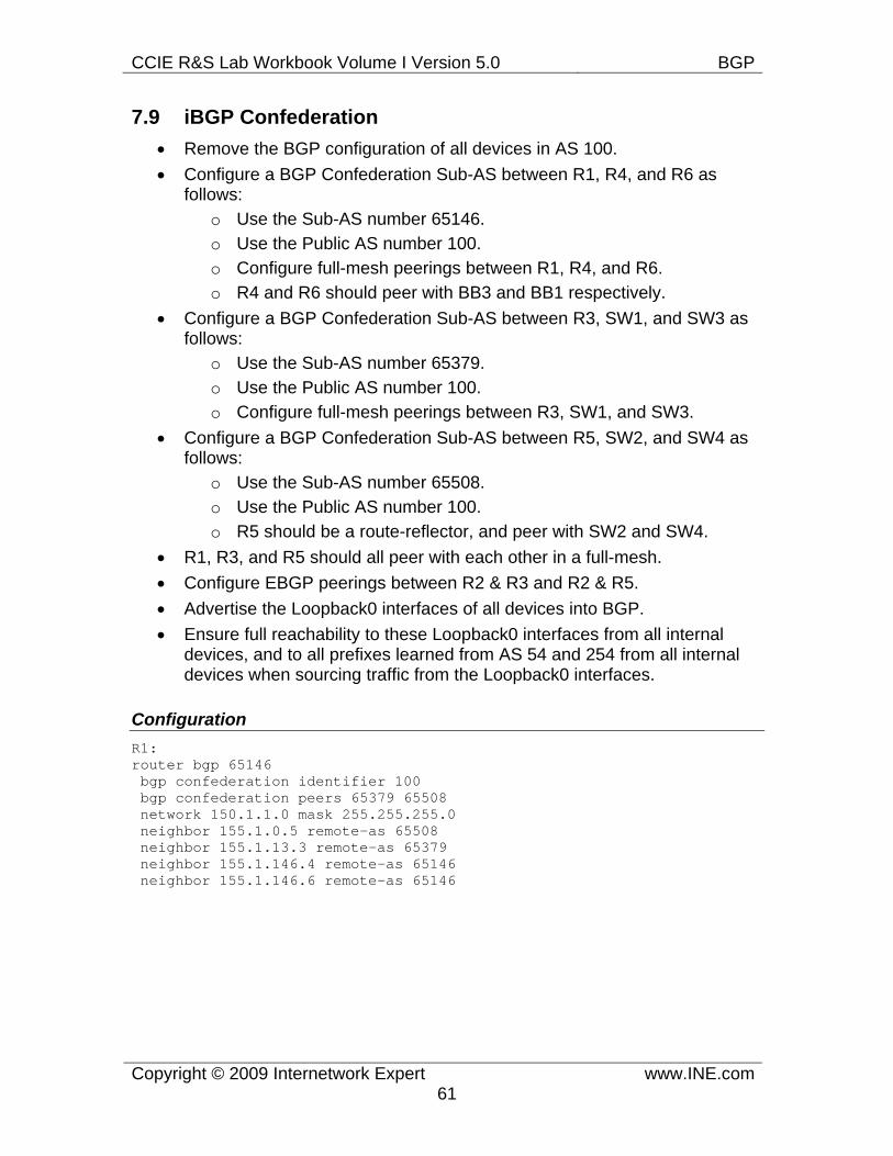
CCIE R&S Lab Workbook Volume I Version 5.0 BGP
Copyright © 2009 Internetwork Expert www.INE.com61
7.9 iBGP Confederation • Remove the BGP configuration of all devices in AS 100. • Configure a BGP Confederation Sub-AS between R1, R4, and R6 as
follows: o Use the Sub-AS number 65146. o Use the Public AS number 100. o Configure full-mesh peerings between R1, R4, and R6. o R4 and R6 should peer with BB3 and BB1 respectively.
• Configure a BGP Confederation Sub-AS between R3, SW1, and SW3 as follows:
o Use the Sub-AS number 65379. o Use the Public AS number 100. o Configure full-mesh peerings between R3, SW1, and SW3.
• Configure a BGP Confederation Sub-AS between R5, SW2, and SW4 as follows:
o Use the Sub-AS number 65508. o Use the Public AS number 100. o R5 should be a route-reflector, and peer with SW2 and SW4.
• R1, R3, and R5 should all peer with each other in a full-mesh. • Configure EBGP peerings between R2 & R3 and R2 & R5. • Advertise the Loopback0 interfaces of all devices into BGP. • Ensure full reachability to these Loopback0 interfaces from all internal
devices, and to all prefixes learned from AS 54 and 254 from all internal devices when sourcing traffic from the Loopback0 interfaces.
Configuration R1: router bgp 65146 bgp confederation identifier 100 bgp confederation peers 65379 65508 network 150.1.1.0 mask 255.255.255.0 neighbor 155.1.0.5 remote-as 65508 neighbor 155.1.13.3 remote-as 65379 neighbor 155.1.146.4 remote-as 65146 neighbor 155.1.146.6 remote-as 65146
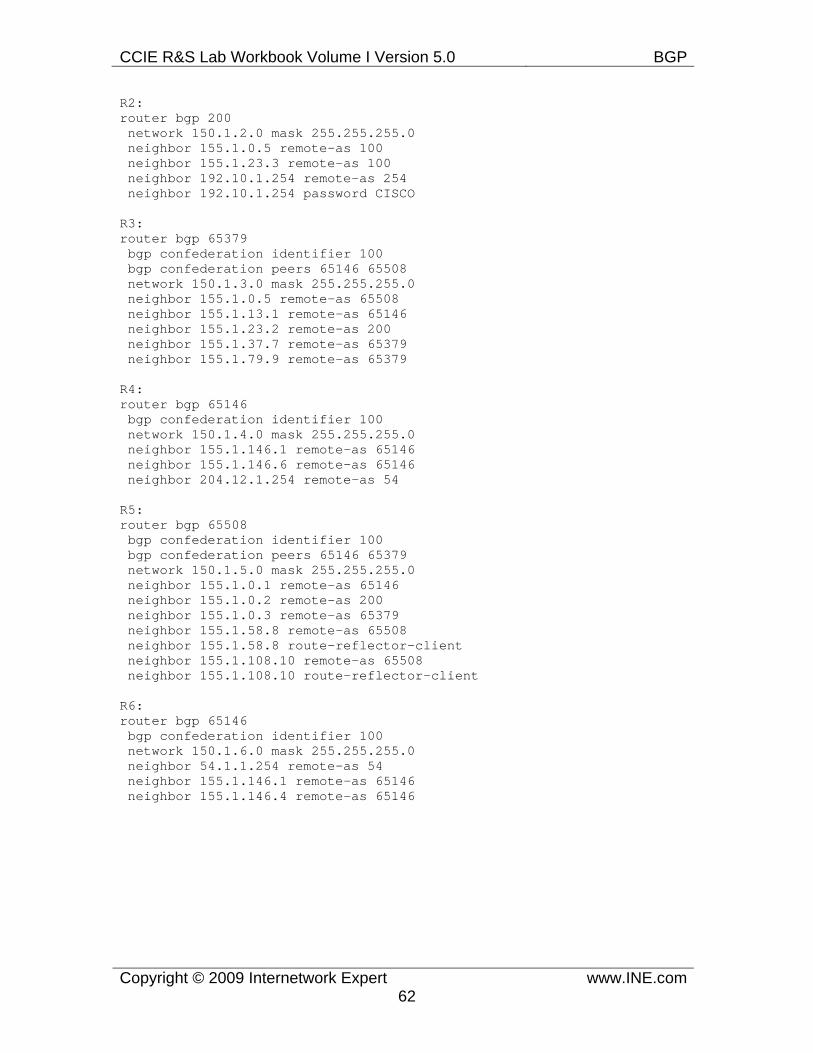
CCIE R&S Lab Workbook Volume I Version 5.0 BGP
Copyright © 2009 Internetwork Expert www.INE.com62
R2: router bgp 200 network 150.1.2.0 mask 255.255.255.0 neighbor 155.1.0.5 remote-as 100 neighbor 155.1.23.3 remote-as 100 neighbor 192.10.1.254 remote-as 254 neighbor 192.10.1.254 password CISCO
R3: router bgp 65379 bgp confederation identifier 100 bgp confederation peers 65146 65508 network 150.1.3.0 mask 255.255.255.0 neighbor 155.1.0.5 remote-as 65508 neighbor 155.1.13.1 remote-as 65146 neighbor 155.1.23.2 remote-as 200 neighbor 155.1.37.7 remote-as 65379 neighbor 155.1.79.9 remote-as 65379
R4: router bgp 65146 bgp confederation identifier 100 network 150.1.4.0 mask 255.255.255.0 neighbor 155.1.146.1 remote-as 65146 neighbor 155.1.146.6 remote-as 65146 neighbor 204.12.1.254 remote-as 54
R5: router bgp 65508 bgp confederation identifier 100 bgp confederation peers 65146 65379 network 150.1.5.0 mask 255.255.255.0 neighbor 155.1.0.1 remote-as 65146 neighbor 155.1.0.2 remote-as 200 neighbor 155.1.0.3 remote-as 65379 neighbor 155.1.58.8 remote-as 65508 neighbor 155.1.58.8 route-reflector-client neighbor 155.1.108.10 remote-as 65508 neighbor 155.1.108.10 route-reflector-client
R6: router bgp 65146 bgp confederation identifier 100 network 150.1.6.0 mask 255.255.255.0 neighbor 54.1.1.254 remote-as 54 neighbor 155.1.146.1 remote-as 65146 neighbor 155.1.146.4 remote-as 65146
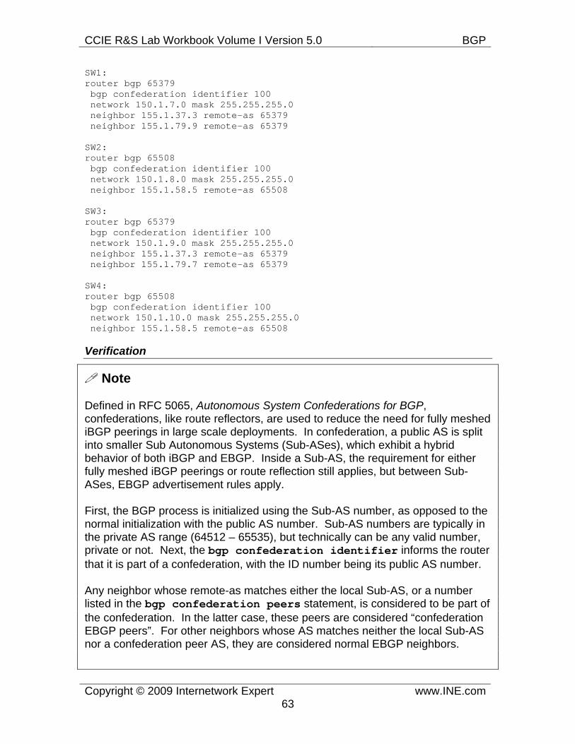
CCIE R&S Lab Workbook Volume I Version 5.0 BGP
Copyright © 2009 Internetwork Expert www.INE.com63
SW1: router bgp 65379 bgp confederation identifier 100 network 150.1.7.0 mask 255.255.255.0 neighbor 155.1.37.3 remote-as 65379 neighbor 155.1.79.9 remote-as 65379
SW2: router bgp 65508 bgp confederation identifier 100 network 150.1.8.0 mask 255.255.255.0 neighbor 155.1.58.5 remote-as 65508
SW3: router bgp 65379 bgp confederation identifier 100 network 150.1.9.0 mask 255.255.255.0 neighbor 155.1.37.3 remote-as 65379 neighbor 155.1.79.7 remote-as 65379
SW4: router bgp 65508 bgp confederation identifier 100 network 150.1.10.0 mask 255.255.255.0 neighbor 155.1.58.5 remote-as 65508
Verification
Note
Defined in RFC 5065, Autonomous System Confederations for BGP, confederations, like route reflectors, are used to reduce the need for fully meshed iBGP peerings in large scale deployments. In confederation, a public AS is split into smaller Sub Autonomous Systems (Sub-ASes), which exhibit a hybrid behavior of both iBGP and EBGP. Inside a Sub-AS, the requirement for either fully meshed iBGP peerings or route reflection still applies, but between Sub-ASes, EBGP advertisement rules apply.
First, the BGP process is initialized using the Sub-AS number, as opposed to the normal initialization with the public AS number. Sub-AS numbers are typically in the private AS range (64512 – 65535), but technically can be any valid number, private or not. Next, the bgp confederation identifier informs the router that it is part of a confederation, with the ID number being its public AS number.
Any neighbor whose remote-as matches either the local Sub-AS, or a number listed in the bgp confederation peers statement, is considered to be part of the confederation. In the latter case, these peers are considered “confederation EBGP peers”. For other neighbors whose AS matches neither the local Sub-AS nor a confederation peer AS, they are considered normal EBGP neighbors.
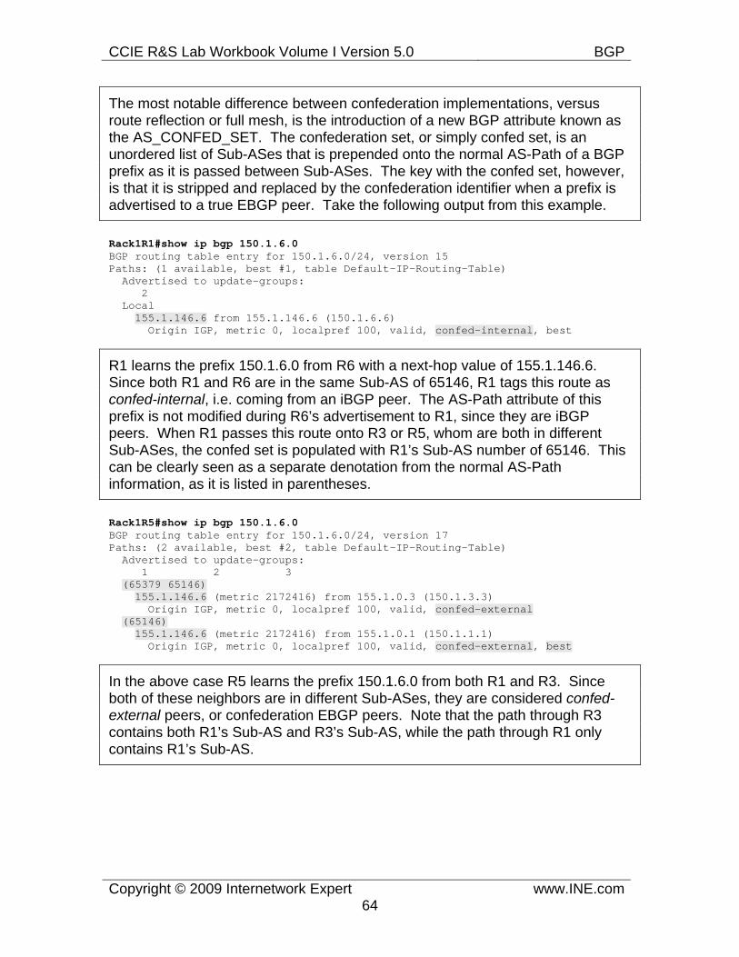
CCIE R&S Lab Workbook Volume I Version 5.0 BGP
Copyright © 2009 Internetwork Expert www.INE.com64
The most notable difference between confederation implementations, versus route reflection or full mesh, is the introduction of a new BGP attribute known as the AS_CONFED_SET. The confederation set, or simply confed set, is an unordered list of Sub-ASes that is prepended onto the normal AS-Path of a BGP prefix as it is passed between Sub-ASes. The key with the confed set, however, is that it is stripped and replaced by the confederation identifier when a prefix is advertised to a true EBGP peer. Take the following output from this example.
Rack1R1#show ip bgp 150.1.6.0 BGP routing table entry for 150.1.6.0/24, version 15 Paths: (1 available, best #1, table Default-IP-Routing-Table) Advertised to update-groups: 2 Local 155.1.146.6 from 155.1.146.6 (150.1.6.6) Origin IGP, metric 0, localpref 100, valid, confed-internal, best
R1 learns the prefix 150.1.6.0 from R6 with a next-hop value of 155.1.146.6. Since both R1 and R6 are in the same Sub-AS of 65146, R1 tags this route as confed-internal, i.e. coming from an iBGP peer. The AS-Path attribute of this prefix is not modified during R6’s advertisement to R1, since they are iBGP peers. When R1 passes this route onto R3 or R5, whom are both in different Sub-ASes, the confed set is populated with R1’s Sub-AS number of 65146. This can be clearly seen as a separate denotation from the normal AS-Path information, as it is listed in parentheses.
Rack1R5#show ip bgp 150.1.6.0 BGP routing table entry for 150.1.6.0/24, version 17 Paths: (2 available, best #2, table Default-IP-Routing-Table) Advertised to update-groups: 1 2 3 (65379 65146) 155.1.146.6 (metric 2172416) from 155.1.0.3 (150.1.3.3) Origin IGP, metric 0, localpref 100, valid, confed-external (65146) 155.1.146.6 (metric 2172416) from 155.1.0.1 (150.1.1.1) Origin IGP, metric 0, localpref 100, valid, confed-external, best
In the above case R5 learns the prefix 150.1.6.0 from both R1 and R3. Since both of these neighbors are in different Sub-ASes, they are considered confed-external peers, or confederation EBGP peers. Note that the path through R3 contains both R1’s Sub-AS and R3’s Sub-AS, while the path through R1 only contains R1’s Sub-AS.
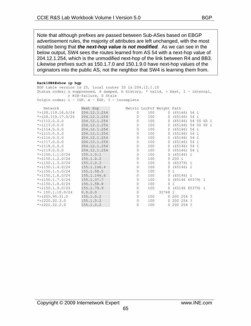
CCIE R&S Lab Workbook Volume I Version 5.0 BGP
Copyright © 2009 Internetwork Expert www.INE.com65
Note that although prefixes are passed between Sub-ASes based on EBGP advertisement rules, the majority of attributes are left unchanged, with the most notable being that the next-hop value is not modified. As we can see in the below output, SW4 sees the routes learned from AS 54 with a next-hop value of 204.12.1.254, which is the unmodified next-hop of the link between R4 and BB3. Likewise prefixes such as 150.1.7.0 and 150.1.9.0 have next-hop values of the originators into the public AS, not the neighbor that SW4 is learning them from.
Rack1SW4#show ip bgp BGP table version is 25, local router ID is 204.12.1.10 Status codes: s suppressed, d damped, h history, * valid, > best, i - internal, r RIB-failure, S Stale Origin codes: i - IGP, e - EGP, ? - incomplete
Network Next Hop Metric LocPrf Weight Path *>i28.119.16.0/24 204.12.1.254 0 100 0 (65146) 54 i *>i28.119.17.0/24 204.12.1.254 0 100 0 (65146) 54 i *>i112.0.0.0 204.12.1.254 0 100 0 (65146) 54 50 60 i *>i113.0.0.0 204.12.1.254 0 100 0 (65146) 54 50 60 i *>i114.0.0.0 204.12.1.254 0 100 0 (65146) 54 i *>i115.0.0.0 204.12.1.254 0 100 0 (65146) 54 i *>i116.0.0.0 204.12.1.254 0 100 0 (65146) 54 i *>i117.0.0.0 204.12.1.254 0 100 0 (65146) 54 i *>i118.0.0.0 204.12.1.254 0 100 0 (65146) 54 i *>i119.0.0.0 204.12.1.254 0 100 0 (65146) 54 i *>i150.1.1.0/24 155.1.0.1 0 100 0 (65146) i *>i150.1.2.0/24 155.1.0.2 0 100 0 200 i *>i150.1.3.0/24 155.1.0.3 0 100 0 (65379) i *>i150.1.4.0/24 155.1.146.4 0 100 0 (65146) i *>i150.1.5.0/24 155.1.58.5 0 100 0 i *>i150.1.6.0/24 155.1.146.6 0 100 0 (65146) i *>i150.1.7.0/24 155.1.37.7 0 100 0 (65146 65379) i *>i150.1.8.0/24 155.1.58.8 0 100 0 i *>i150.1.9.0/24 155.1.79.9 0 100 0 (65146 65379) i *> 150.1.10.0/24 0.0.0.0 0 32768 i *>i205.90.31.0 155.1.0.2 0 100 0 200 254 ? *>i220.20.3.0 155.1.0.2 0 100 0 200 254 ? *>i222.22.2.0 155.1.0.2 0 100 0 200 254 ?
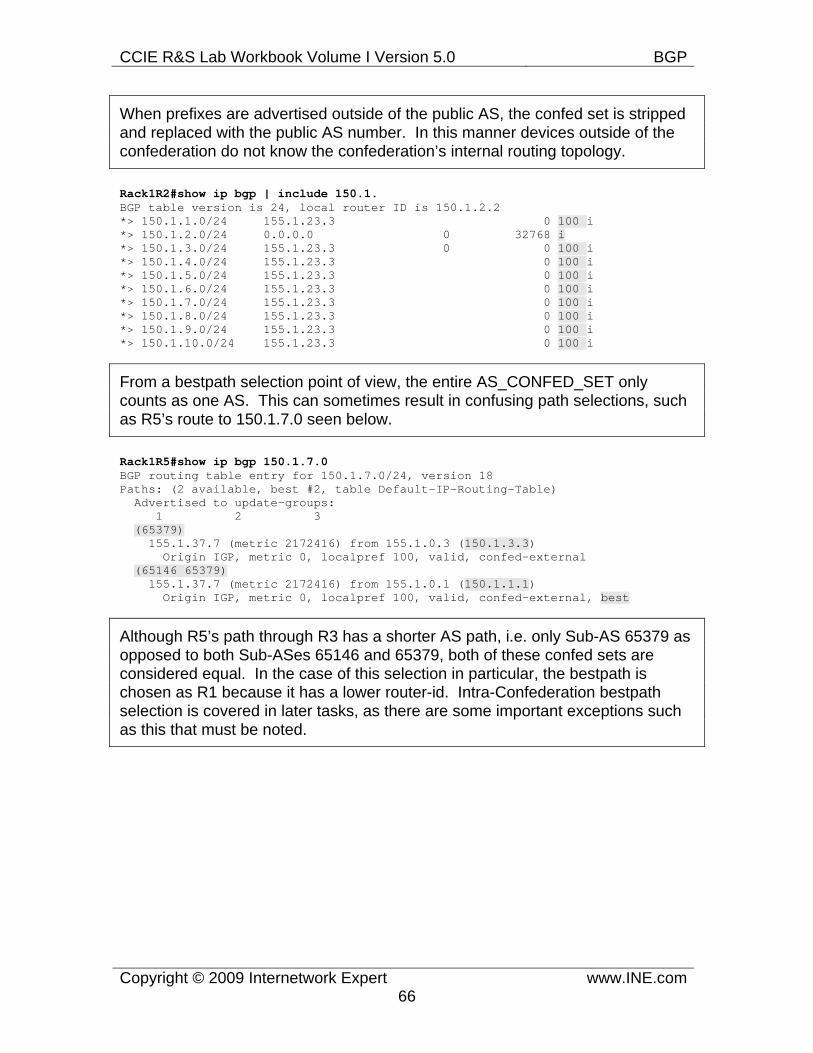
CCIE R&S Lab Workbook Volume I Version 5.0 BGP
Copyright © 2009 Internetwork Expert www.INE.com66
When prefixes are advertised outside of the public AS, the confed set is stripped and replaced with the public AS number. In this manner devices outside of the confederation do not know the confederation’s internal routing topology.
Rack1R2#show ip bgp | include 150.1. BGP table version is 24, local router ID is 150.1.2.2 *> 150.1.1.0/24 155.1.23.3 0 100 i *> 150.1.2.0/24 0.0.0.0 0 32768 i *> 150.1.3.0/24 155.1.23.3 0 0 100 i *> 150.1.4.0/24 155.1.23.3 0 100 i *> 150.1.5.0/24 155.1.23.3 0 100 i *> 150.1.6.0/24 155.1.23.3 0 100 i *> 150.1.7.0/24 155.1.23.3 0 100 i *> 150.1.8.0/24 155.1.23.3 0 100 i *> 150.1.9.0/24 155.1.23.3 0 100 i *> 150.1.10.0/24 155.1.23.3 0 100 i
From a bestpath selection point of view, the entire AS_CONFED_SET only counts as one AS. This can sometimes result in confusing path selections, such as R5’s route to 150.1.7.0 seen below.
Rack1R5#show ip bgp 150.1.7.0 BGP routing table entry for 150.1.7.0/24, version 18 Paths: (2 available, best #2, table Default-IP-Routing-Table) Advertised to update-groups: 1 2 3 (65379) 155.1.37.7 (metric 2172416) from 155.1.0.3 (150.1.3.3) Origin IGP, metric 0, localpref 100, valid, confed-external (65146 65379) 155.1.37.7 (metric 2172416) from 155.1.0.1 (150.1.1.1) Origin IGP, metric 0, localpref 100, valid, confed-external, best
Although R5’s path through R3 has a shorter AS path, i.e. only Sub-AS 65379 as opposed to both Sub-ASes 65146 and 65379, both of these confed sets are considered equal. In the case of this selection in particular, the bestpath is chosen as R1 because it has a lower router-id. Intra-Confederation bestpath selection is covered in later tasks, as there are some important exceptions such as this that must be noted.
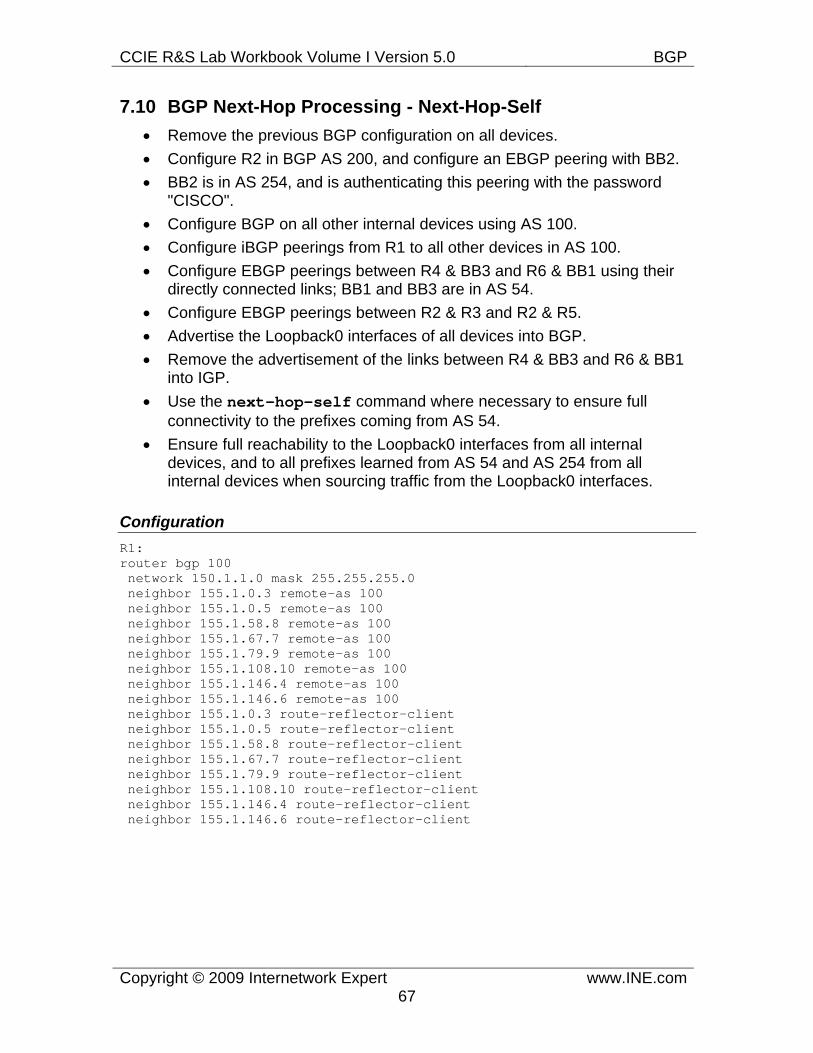
CCIE R&S Lab Workbook Volume I Version 5.0 BGP
Copyright © 2009 Internetwork Expert www.INE.com67
7.10 BGP Next-Hop Processing - Next-Hop-Self • Remove the previous BGP configuration on all devices. • Configure R2 in BGP AS 200, and configure an EBGP peering with BB2. • BB2 is in AS 254, and is authenticating this peering with the password
"CISCO". • Configure BGP on all other internal devices using AS 100. • Configure iBGP peerings from R1 to all other devices in AS 100. • Configure EBGP peerings between R4 & BB3 and R6 & BB1 using their
directly connected links; BB1 and BB3 are in AS 54. • Configure EBGP peerings between R2 & R3 and R2 & R5. • Advertise the Loopback0 interfaces of all devices into BGP. • Remove the advertisement of the links between R4 & BB3 and R6 & BB1
into IGP. • Use the next-hop-self command where necessary to ensure full
connectivity to the prefixes coming from AS 54. • Ensure full reachability to the Loopback0 interfaces from all internal
devices, and to all prefixes learned from AS 54 and AS 254 from all internal devices when sourcing traffic from the Loopback0 interfaces.
Configuration R1: router bgp 100 network 150.1.1.0 mask 255.255.255.0 neighbor 155.1.0.3 remote-as 100 neighbor 155.1.0.5 remote-as 100 neighbor 155.1.58.8 remote-as 100 neighbor 155.1.67.7 remote-as 100 neighbor 155.1.79.9 remote-as 100 neighbor 155.1.108.10 remote-as 100 neighbor 155.1.146.4 remote-as 100 neighbor 155.1.146.6 remote-as 100 neighbor 155.1.0.3 route-reflector-client neighbor 155.1.0.5 route-reflector-client neighbor 155.1.58.8 route-reflector-client neighbor 155.1.67.7 route-reflector-client neighbor 155.1.79.9 route-reflector-client neighbor 155.1.108.10 route-reflector-client neighbor 155.1.146.4 route-reflector-client neighbor 155.1.146.6 route-reflector-client
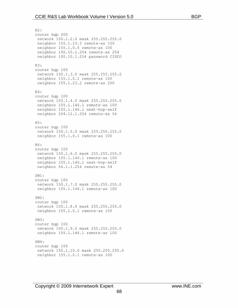
CCIE R&S Lab Workbook Volume I Version 5.0 BGP
Copyright © 2009 Internetwork Expert www.INE.com68
R2: router bgp 200 network 150.1.2.0 mask 255.255.255.0 neighbor 155.1.23.3 remote-as 100 neighbor 155.1.0.5 remote-as 100 neighbor 192.10.1.254 remote-as 254 neighbor 192.10.1.254 password CISCO
R3: router bgp 100 network 150.1.3.0 mask 255.255.255.0 neighbor 155.1.0.1 remote-as 100 neighbor 155.1.23.2 remote-as 200
R4: router bgp 100 network 150.1.4.0 mask 255.255.255.0 neighbor 155.1.146.1 remote-as 100 neighbor 155.1.146.1 next-hop-self neighbor 204.12.1.254 remote-as 54
R5: router bgp 100 network 150.1.5.0 mask 255.255.255.0 neighbor 155.1.0.1 remote-as 100 R6: router bgp 100 network 150.1.6.0 mask 255.255.255.0 neighbor 155.1.146.1 remote-as 100 neighbor 155.1.146.1 next-hop-self neighbor 54.1.1.254 remote-as 54
SW1: router bgp 100 network 150.1.7.0 mask 255.255.255.0 neighbor 155.1.146.1 remote-as 100
SW2: router bgp 100 network 150.1.8.0 mask 255.255.255.0 neighbor 155.1.0.1 remote-as 100 SW3: router bgp 100 network 150.1.9.0 mask 255.255.255.0 neighbor 155.1.146.1 remote-as 100
SW4: router bgp 100 network 150.1.10.0 mask 255.255.255.0 neighbor 155.1.0.1 remote-as 100
CCIE R&S Lab Workbook Volume I Version 5.0 BGP
Copyright © 2009 Internetwork Expert www.INE.com69
Verification
Note
Recall from the IP Routing section how the route recursion process works. When the longest match route is found for the destination in question, the next-hop value of the prefix is checked. If the longest match to the next-hop value is a connected route, the outgoing interface is known, the layer 2 address is found – depending on the media – and the frame is built for transmission. If the next-hop value is not via a connected interface, additional routing lookups must be performed (i.e. “recursive” lookups) until an outgoing interface is found.
With IGP routing this process is usually transparent, because in the vast majority of cases routes are always learned from directly connected neighbors. For example, if an OSPF route is learned from neighbor A via interface X, it is safe to assume that interface X will be used to reach that destination. However, with BGP, a disconnect can occur between the neighbor prefixes are learned from (the control plane), and the actual path packets take towards the prefix (the forwarding/data plane). The main reason for this is that in many cases, BGP neighbors are not directly connected, but instead exchange BGP control plane information over additional hops in the network. This process can occur because IGP information provides reachability to establish the TCP transport inherent to the BGP control plane.
In order to ensure that this disconnect does not adversely affect the actual forwarding of traffic, the BGP process internally performs the route recursion process for all prefixes prior to performing Bestpath selection. If route recursion is not successful, e.g. the final outgoing interface cannot be found, the prefix cannot be considered for Bestpath selection. This implies that the prefix cannot be installed in the IP routing table, nor can it be advertised to any other BGP peers. In this particular example, this problem can be illustrated in AS 100 by the routes that are learned from AS 54.
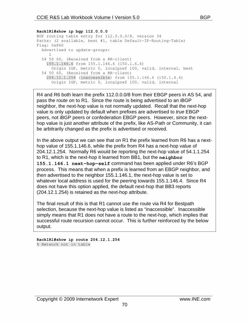
CCIE R&S Lab Workbook Volume I Version 5.0 BGP
Copyright © 2009 Internetwork Expert www.INE.com70
Rack1R1#show ip bgp 112.0.0.0 BGP routing table entry for 112.0.0.0/8, version 34 Paths: (2 available, best #1, table Default-IP-Routing-Table) Flag: 0x860 Advertised to update-groups: 1 54 50 60, (Received from a RR-client) 155.1.146.6 from 155.1.146.6 (150.1.6.6) Origin IGP, metric 0, localpref 100, valid, internal, best 54 50 60, (Received from a RR-client) 204.12.1.254 (inaccessible) from 155.1.146.4 (150.1.4.4) Origin IGP, metric 0, localpref 100, valid, internal
R4 and R6 both learn the prefix 112.0.0.0/8 from their EBGP peers in AS 54, and pass the route on to R1. Since the route is being advertised to an iBGP neighbor, the next-hop value is not normally updated. Recall that the next-hop value is only updated by default when prefixes are advertised to true EBGP peers, not iBGP peers or confederation EBGP peers. However, since the next-hop value is just another attribute of the prefix, like AS-Path or Community, it can be arbitrarily changed as the prefix is advertised or received.
In the above output we can see that on R1 the prefix learned from R6 has a next-hop value of 155.1.146.6, while the prefix from R4 has a next-hop value of 204.12.1.254. Normally R6 would be reporting the next-hop value of 54.1.1.254 to R1, which is the next-hop it learned from BB1, but the neighbor 155.1.146.1 next-hop-self command has been applied under R6’s BGP process. This means that when a prefix is learned from an EBGP neighbor, and then advertised to the neighbor 155.1.146.1, the next-hop value is set to whatever local address is used for the peering towards 155.1.146.4. Since R4 does not have this option applied, the default next-hop that BB3 reports (204.12.1.254) is retained as the next-hop attribute.
The final result of this is that R1 cannot use the route via R4 for Bestpath selection, because the next-hop value is listed as “inaccessible”. Inaccessible simply means that R1 does not have a route to the next-hop, which implies that successful route recursion cannot occur. This is further reinforced by the below output.
Rack1R1#show ip route 204.12.1.254 % Network not in table
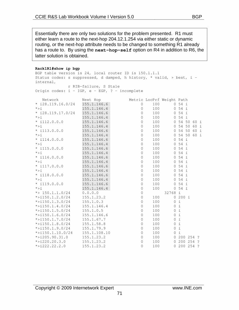
CCIE R&S Lab Workbook Volume I Version 5.0 BGP
Copyright © 2009 Internetwork Expert www.INE.com71
Essentially there are only two solutions for the problem presented. R1 must either learn a route to the next-hop 204.12.1.254 via either static or dynamic routing, or the next-hop attribute needs to be changed to something R1 already has a route to. By using the next-hop-self option on R4 in addition to R6, the latter solution is obtained.
Rack1R1#show ip bgp BGP table version is 24, local router ID is 150.1.1.1 Status codes: s suppressed, d damped, h history, * valid, > best, i - internal, r RIB-failure, S Stale Origin codes: i - IGP, e - EGP, ? - incomplete
Network Next Hop Metric LocPrf Weight Path * i28.119.16.0/24 155.1.146.6 0 100 0 54 i *>i 155.1.146.4 0 100 0 54 i * i28.119.17.0/24 155.1.146.6 0 100 0 54 i *>i 155.1.146.4 0 100 0 54 i * i112.0.0.0 155.1.146.6 0 100 0 54 50 60 i *>i 155.1.146.4 0 100 0 54 50 60 i * i113.0.0.0 155.1.146.6 0 100 0 54 50 60 i *>i 155.1.146.4 0 100 0 54 50 60 i * i114.0.0.0 155.1.146.6 0 100 0 54 i *>i 155.1.146.4 0 100 0 54 i * i115.0.0.0 155.1.146.6 0 100 0 54 i *>i 155.1.146.4 0 100 0 54 i * i116.0.0.0 155.1.146.6 0 100 0 54 i *>i 155.1.146.4 0 100 0 54 i * i117.0.0.0 155.1.146.6 0 100 0 54 i *>i 155.1.146.4 0 100 0 54 i * i118.0.0.0 155.1.146.6 0 100 0 54 i *>i 155.1.146.4 0 100 0 54 i * i119.0.0.0 155.1.146.6 0 100 0 54 i *>i 155.1.146.4 0 100 0 54 i *> 150.1.1.0/24 0.0.0.0 0 32768 i *>i150.1.2.0/24 155.1.23.2 0 100 0 200 i *>i150.1.3.0/24 155.1.0.3 0 100 0 i *>i150.1.4.0/24 155.1.146.4 0 100 0 i *>i150.1.5.0/24 155.1.0.5 0 100 0 i *>i150.1.6.0/24 155.1.146.6 0 100 0 i *>i150.1.7.0/24 155.1.67.7 0 100 0 i *>i150.1.8.0/24 155.1.58.8 0 100 0 i *>i150.1.9.0/24 155.1.79.9 0 100 0 i *>i150.1.10.0/24 155.1.108.10 0 100 0 i *>i205.90.31.0 155.1.23.2 0 100 0 200 254 ? *>i220.20.3.0 155.1.23.2 0 100 0 200 254 ? *>i222.22.2.0 155.1.23.2 0 100 0 200 254 ?
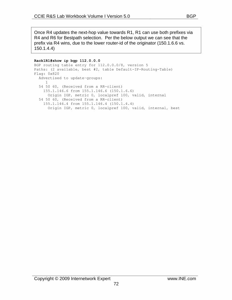
CCIE R&S Lab Workbook Volume I Version 5.0 BGP
Copyright © 2009 Internetwork Expert www.INE.com72
Once R4 updates the next-hop value towards R1, R1 can use both prefixes via R4 and R6 for Bestpath selection. Per the below output we can see that the prefix via R4 wins, due to the lower router-id of the originator (150.1.6.6 vs. 150.1.4.4)
Rack1R1#show ip bgp 112.0.0.0 BGP routing table entry for 112.0.0.0/8, version 5 Paths: (2 available, best #2, table Default-IP-Routing-Table) Flag: 0x820 Advertised to update-groups: 1 54 50 60, (Received from a RR-client) 155.1.146.6 from 155.1.146.6 (150.1.6.6) Origin IGP, metric 0, localpref 100, valid, internal 54 50 60, (Received from a RR-client) 155.1.146.4 from 155.1.146.4 (150.1.4.4) Origin IGP, metric 0, localpref 100, valid, internal, best
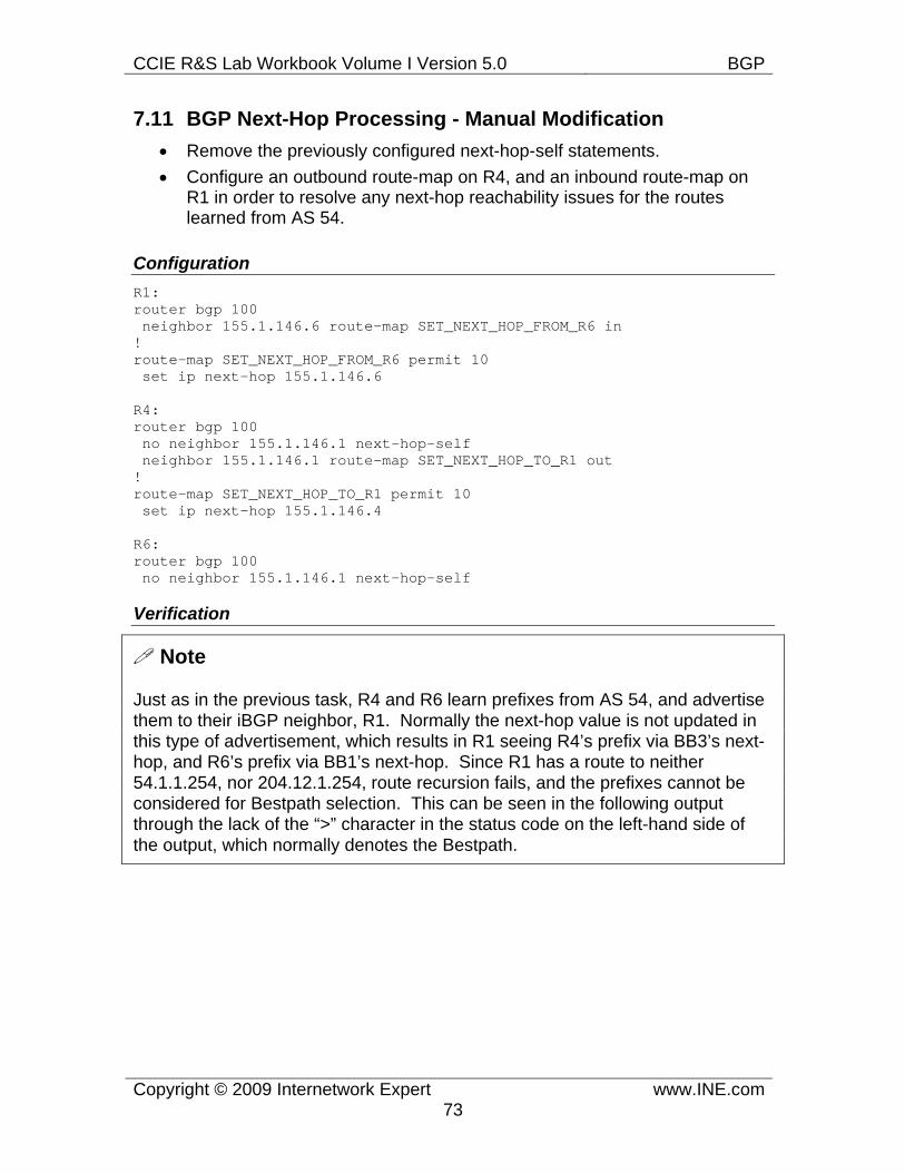
CCIE R&S Lab Workbook Volume I Version 5.0 BGP
Copyright © 2009 Internetwork Expert www.INE.com73
7.11 BGP Next-Hop Processing - Manual Modification • Remove the previously configured next-hop-self statements. • Configure an outbound route-map on R4, and an inbound route-map on
R1 in order to resolve any next-hop reachability issues for the routes learned from AS 54.
Configuration R1: router bgp 100 neighbor 155.1.146.6 route-map SET_NEXT_HOP_FROM_R6 in ! route-map SET_NEXT_HOP_FROM_R6 permit 10 set ip next-hop 155.1.146.6
R4: router bgp 100 no neighbor 155.1.146.1 next-hop-self neighbor 155.1.146.1 route-map SET_NEXT_HOP_TO_R1 out ! route-map SET_NEXT_HOP_TO_R1 permit 10 set ip next-hop 155.1.146.4
R6: router bgp 100 no neighbor 155.1.146.1 next-hop-self
Verification
Note
Just as in the previous task, R4 and R6 learn prefixes from AS 54, and advertise them to their iBGP neighbor, R1. Normally the next-hop value is not updated in this type of advertisement, which results in R1 seeing R4’s prefix via BB3’s next-hop, and R6’s prefix via BB1’s next-hop. Since R1 has a route to neither 54.1.1.254, nor 204.12.1.254, route recursion fails, and the prefixes cannot be considered for Bestpath selection. This can be seen in the following output through the lack of the “>” character in the status code on the left-hand side of the output, which normally denotes the Bestpath.
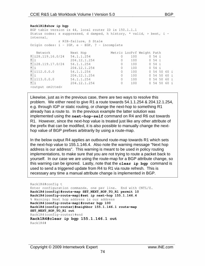
CCIE R&S Lab Workbook Volume I Version 5.0 BGP
Copyright © 2009 Internetwork Expert www.INE.com74
Rack1R1#show ip bgp BGP table version is 44, local router ID is 150.1.1.1 Status codes: s suppressed, d damped, h history, * valid, > best, i - internal, r RIB-failure, S Stale Origin codes: i - IGP, e - EGP, ? - incomplete
Network Next Hop Metric LocPrf Weight Path * i28.119.16.0/24 54.1.1.254 0 100 0 54 i * i 204.12.1.254 0 100 0 54 i * i28.119.17.0/24 54.1.1.254 0 100 0 54 i * i 204.12.1.254 0 100 0 54 i * i112.0.0.0 54.1.1.254 0 100 0 54 50 60 i * i 204.12.1.254 0 100 0 54 50 60 i * i113.0.0.0 54.1.1.254 0 100 0 54 50 60 i * i 204.12.1.254 0 100 0 54 50 60 i <output omitted>
Likewise, just as in the previous case, there are two ways to resolve this problem. We either need to give R1 a route towards 54.1.1.254 & 204.12.1.254, e.g. through IGP or static routing, or change the next-hop to something R1 already has a route to. In the previous example the latter solution was implemented using the next-hop-self command on R4 and R6 out towards R1. However, since the next-hop value is treated just like any other attribute of the prefix that can be modified, it is also possible to manually change the next-hop value of BGP prefixes arbitrarily by using a route-map.
In the below output R4 applies an outbound route-map towards R1 which sets the next-hop value to 155.1.146.4. Also note the warning message “Next hop address is our address”. This warning is meant to be used in policy routing implementations, to make sure that you are not trying to route a packet back to yourself. In our case we are using the route-map for a BGP attribute change, so this warning can be ignored. Lastly, note that the clear ip bgp command is used to send a triggered update from R4 to R1 via route refresh. This is necessary any time a manual attribute change is implemented in BGP.
Rack1R4#config t Enter configuration commands, one per line. End with CNTL/Z. Rack1R4(config)#route-map SET_NEXT_HOP_TO_R1 permit 10 Rack1R4(config-route-map)#set ip next-hop 155.1.146.4 % Warning: Next hop address is our address Rack1R4(config-route-map)#router bgp 100 Rack1R4(config-router)#neighbor 155.1.146.1 route-map SET_NEXT_HOP_TO_R1 out Rack1R4(config-router)#end Rack1R4#clear ip bgp 155.1.146.1 out Rack1R4#
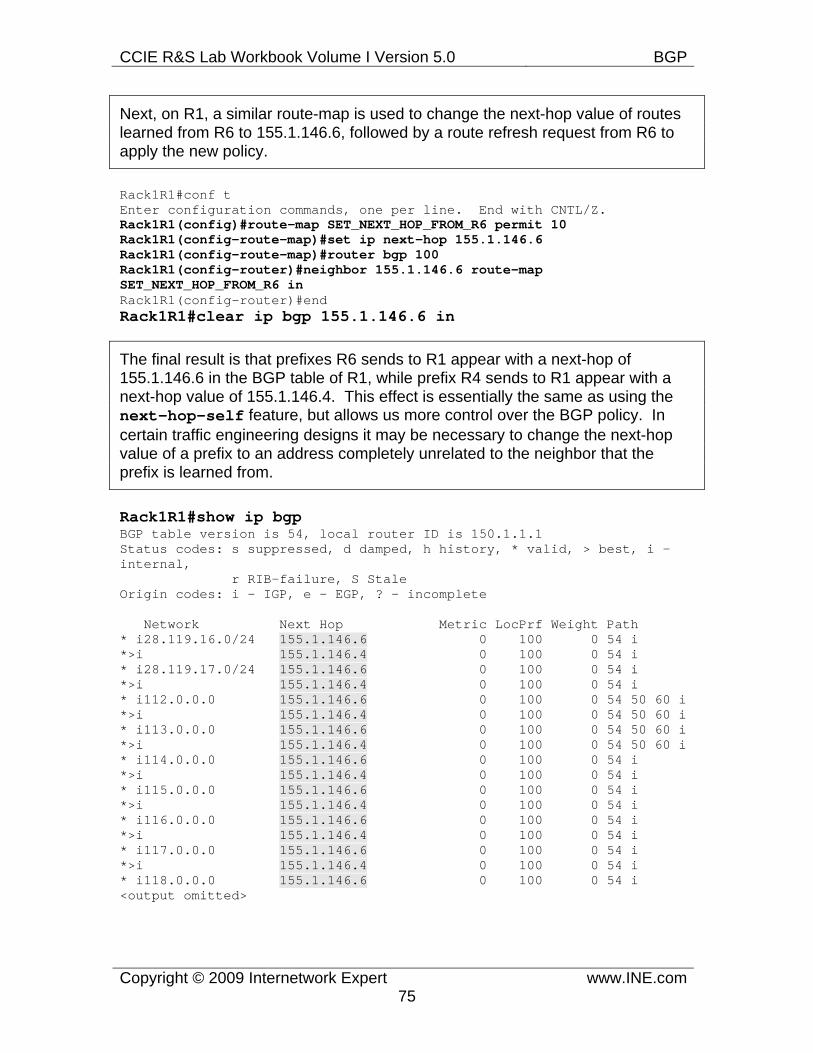
CCIE R&S Lab Workbook Volume I Version 5.0 BGP
Copyright © 2009 Internetwork Expert www.INE.com75
Next, on R1, a similar route-map is used to change the next-hop value of routes learned from R6 to 155.1.146.6, followed by a route refresh request from R6 to apply the new policy.
Rack1R1#conf t Enter configuration commands, one per line. End with CNTL/Z. Rack1R1(config)#route-map SET_NEXT_HOP_FROM_R6 permit 10 Rack1R1(config-route-map)#set ip next-hop 155.1.146.6 Rack1R1(config-route-map)#router bgp 100 Rack1R1(config-router)#neighbor 155.1.146.6 route-map SET_NEXT_HOP_FROM_R6 in Rack1R1(config-router)#end Rack1R1#clear ip bgp 155.1.146.6 in
The final result is that prefixes R6 sends to R1 appear with a next-hop of 155.1.146.6 in the BGP table of R1, while prefix R4 sends to R1 appear with a next-hop value of 155.1.146.4. This effect is essentially the same as using the next-hop-self feature, but allows us more control over the BGP policy. In certain traffic engineering designs it may be necessary to change the next-hop value of a prefix to an address completely unrelated to the neighbor that the prefix is learned from.
Rack1R1#show ip bgp BGP table version is 54, local router ID is 150.1.1.1 Status codes: s suppressed, d damped, h history, * valid, > best, i - internal, r RIB-failure, S Stale Origin codes: i - IGP, e - EGP, ? - incomplete
Network Next Hop Metric LocPrf Weight Path * i28.119.16.0/24 155.1.146.6 0 100 0 54 i *>i 155.1.146.4 0 100 0 54 i * i28.119.17.0/24 155.1.146.6 0 100 0 54 i *>i 155.1.146.4 0 100 0 54 i * i112.0.0.0 155.1.146.6 0 100 0 54 50 60 i *>i 155.1.146.4 0 100 0 54 50 60 i * i113.0.0.0 155.1.146.6 0 100 0 54 50 60 i *>i 155.1.146.4 0 100 0 54 50 60 i * i114.0.0.0 155.1.146.6 0 100 0 54 i *>i 155.1.146.4 0 100 0 54 i * i115.0.0.0 155.1.146.6 0 100 0 54 i *>i 155.1.146.4 0 100 0 54 i * i116.0.0.0 155.1.146.6 0 100 0 54 i *>i 155.1.146.4 0 100 0 54 i * i117.0.0.0 155.1.146.6 0 100 0 54 i *>i 155.1.146.4 0 100 0 54 i * i118.0.0.0 155.1.146.6 0 100 0 54 i <output omitted>
CCIE R&S Lab Workbook Volume I Version 5.0 BGP
Copyright © 2009 Internetwork Expert www.INE.com76
7.12 iBGP Synchronization • Disable iBGP Synchronization on all devices in AS 100. • Ensure full reachability to the Loopback0 interfaces from all internal
devices, and to all prefixes learned from AS 54 and AS 254 from all internal devices when sourcing traffic from the Loopback0 interfaces.
Configuration
Note
Per Cisco’s BGP Bestpath Selection, “if BGP synchronization is enabled, there must be a match for the prefix in the IP routing table in order for an internal BGP (iBGP) path to be considered a valid path.” In other words, for every iBGP route learned, there must be a matching IGP route already before the BGP route can be used. This rule was designed to prevent traffic black holes in legacy network designs where not all devices in the BGP transit path actually ran BGP.
With synchronization enabled, the assumption was that all routers in a transit network already ran IGP. If these devices had IGP routes to all BGP destinations, then it was safe to assume that traffic coming from other BGP ASes would not be black holed, even if some of the internal routers were not running BGP. To implement this design it was also assumed that some sort of BGP to IGP redistribution would occur.
The problem with this model however, is that IGP simply cannot scale to the size of the current Internet BGP table. Instead, current best practices dictate that if a network is used for Internet transit, the routing table should be default free (i.e. no 0.0.0.0/0 routes), and all devices should run BGP. Another common design is that other tunneling mechanisms can be used, such as MPLS, to limit the amount of devices that BGP needs to be run on.
BGP synchronization is disabled by default as of IOS 12.2(8)T, and is rarely, if ever, needed in a real implementation anymore. However it is still important to understand the problem that synchronization was designed to prevent, and what the different resolutions for this problem are.
R1: router eigrp 100 network 150.1.1.1 0.0.0.0 ! router bgp 100 synchronization
R2:
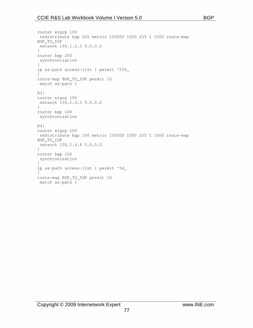
CCIE R&S Lab Workbook Volume I Version 5.0 BGP
Copyright © 2009 Internetwork Expert www.INE.com77
router eigrp 100 redistribute bgp 200 metric 100000 1000 255 1 1500 route-map BGP_TO_IGP network 150.1.2.2 0.0.0.0 ! router bgp 200 synchronization ! ip as-path access-list 1 permit ^254_ ! route-map BGP_TO_IGP permit 10 match as-path 1
R3: router eigrp 100 network 150.1.3.3 0.0.0.0 ! router bgp 100 synchronization
R4: router eigrp 100 redistribute bgp 100 metric 100000 1000 255 1 1500 route-map BGP_TO_IGP network 150.1.4.4 0.0.0.0 ! router bgp 100 synchronization ! ip as-path access-list 1 permit ^54_ ! route-map BGP_TO_IGP permit 10 match as-path 1
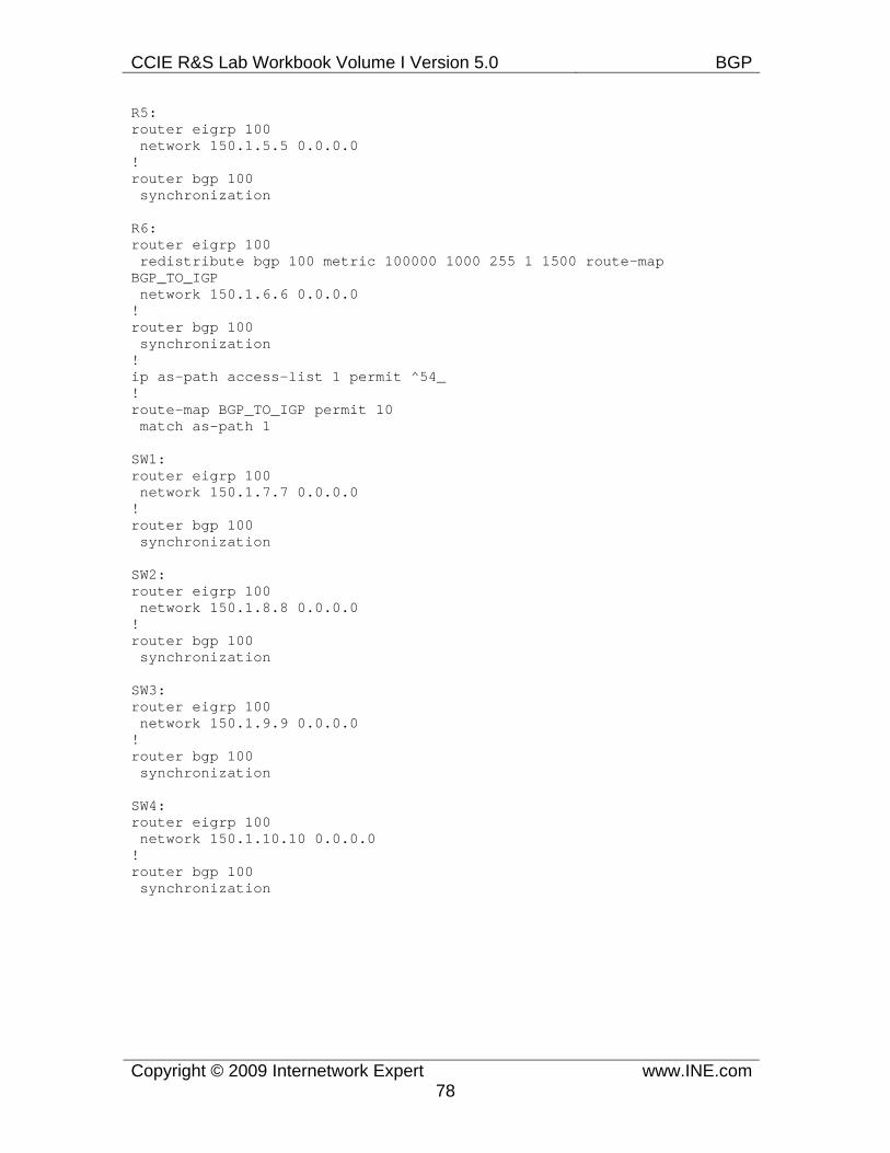
CCIE R&S Lab Workbook Volume I Version 5.0 BGP
Copyright © 2009 Internetwork Expert www.INE.com78
R5: router eigrp 100 network 150.1.5.5 0.0.0.0 ! router bgp 100 synchronization
R6: router eigrp 100 redistribute bgp 100 metric 100000 1000 255 1 1500 route-map BGP_TO_IGP network 150.1.6.6 0.0.0.0 ! router bgp 100 synchronization ! ip as-path access-list 1 permit ^54_ ! route-map BGP_TO_IGP permit 10 match as-path 1
SW1: router eigrp 100 network 150.1.7.7 0.0.0.0 ! router bgp 100 synchronization
SW2: router eigrp 100 network 150.1.8.8 0.0.0.0 ! router bgp 100 synchronization
SW3: router eigrp 100 network 150.1.9.9 0.0.0.0 ! router bgp 100 synchronization
SW4: router eigrp 100 network 150.1.10.10 0.0.0.0 ! router bgp 100 synchronization
CCIE R&S Lab Workbook Volume I Version 5.0 BGP
Copyright © 2009 Internetwork Expert www.INE.com79
Verification
Pitfall
Redistribution between IGP and BGP can be dangerous, causing traffic loops, black holes, and network instability due to memory and CPU resource exhaustion. In the previous configuration only necessary routes are redistributed on R2, R4, and R6 based on the AS-Path attribute. Route-map filtering should always be used when performing this type of redistribution to strictly control which prefixes are candidate for redistribution.
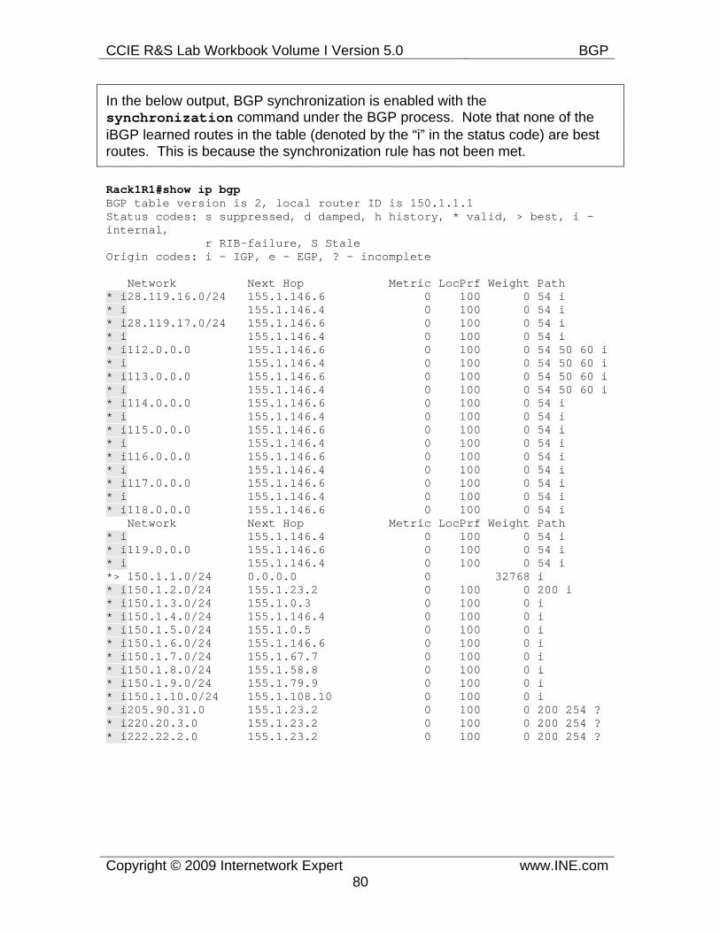
CCIE R&S Lab Workbook Volume I Version 5.0 BGP
Copyright © 2009 Internetwork Expert www.INE.com80
In the below output, BGP synchronization is enabled with the synchronization command under the BGP process. Note that none of the iBGP learned routes in the table (denoted by the “i” in the status code) are best routes. This is because the synchronization rule has not been met.
Rack1R1#show ip bgp BGP table version is 2, local router ID is 150.1.1.1 Status codes: s suppressed, d damped, h history, * valid, > best, i - internal, r RIB-failure, S Stale Origin codes: i - IGP, e - EGP, ? - incomplete
Network Next Hop Metric LocPrf Weight Path * i28.119.16.0/24 155.1.146.6 0 100 0 54 i * i 155.1.146.4 0 100 0 54 i * i28.119.17.0/24 155.1.146.6 0 100 0 54 i * i 155.1.146.4 0 100 0 54 i * i112.0.0.0 155.1.146.6 0 100 0 54 50 60 i * i 155.1.146.4 0 100 0 54 50 60 i * i113.0.0.0 155.1.146.6 0 100 0 54 50 60 i * i 155.1.146.4 0 100 0 54 50 60 i * i114.0.0.0 155.1.146.6 0 100 0 54 i * i 155.1.146.4 0 100 0 54 i * i115.0.0.0 155.1.146.6 0 100 0 54 i * i 155.1.146.4 0 100 0 54 i * i116.0.0.0 155.1.146.6 0 100 0 54 i * i 155.1.146.4 0 100 0 54 i * i117.0.0.0 155.1.146.6 0 100 0 54 i * i 155.1.146.4 0 100 0 54 i * i118.0.0.0 155.1.146.6 0 100 0 54 i Network Next Hop Metric LocPrf Weight Path * i 155.1.146.4 0 100 0 54 i * i119.0.0.0 155.1.146.6 0 100 0 54 i * i 155.1.146.4 0 100 0 54 i *> 150.1.1.0/24 0.0.0.0 0 32768 i * i150.1.2.0/24 155.1.23.2 0 100 0 200 i * i150.1.3.0/24 155.1.0.3 0 100 0 i * i150.1.4.0/24 155.1.146.4 0 100 0 i * i150.1.5.0/24 155.1.0.5 0 100 0 i * i150.1.6.0/24 155.1.146.6 0 100 0 i * i150.1.7.0/24 155.1.67.7 0 100 0 i * i150.1.8.0/24 155.1.58.8 0 100 0 i * i150.1.9.0/24 155.1.79.9 0 100 0 i * i150.1.10.0/24 155.1.108.10 0 100 0 i * i205.90.31.0 155.1.23.2 0 100 0 200 254 ? * i220.20.3.0 155.1.23.2 0 100 0 200 254 ? * i222.22.2.0 155.1.23.2 0 100 0 200 254 ?
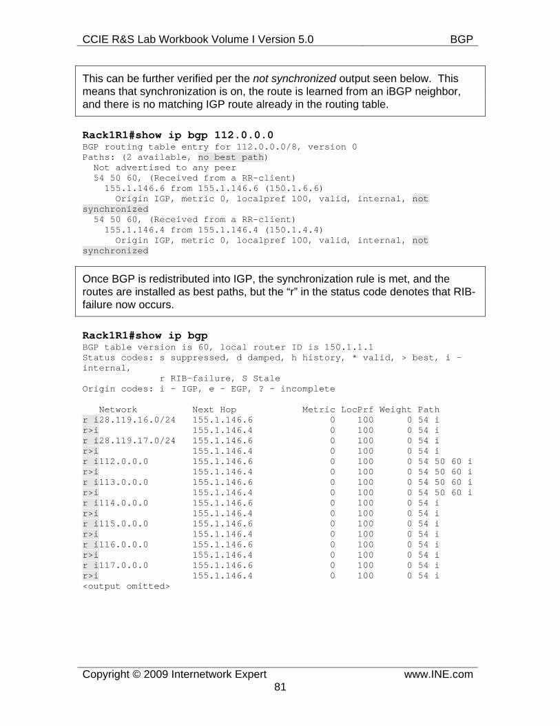
CCIE R&S Lab Workbook Volume I Version 5.0 BGP
Copyright © 2009 Internetwork Expert www.INE.com81
This can be further verified per the not synchronized output seen below. This means that synchronization is on, the route is learned from an iBGP neighbor, and there is no matching IGP route already in the routing table.
Rack1R1#show ip bgp 112.0.0.0 BGP routing table entry for 112.0.0.0/8, version 0 Paths: (2 available, no best path) Not advertised to any peer 54 50 60, (Received from a RR-client) 155.1.146.6 from 155.1.146.6 (150.1.6.6) Origin IGP, metric 0, localpref 100, valid, internal, not synchronized 54 50 60, (Received from a RR-client) 155.1.146.4 from 155.1.146.4 (150.1.4.4) Origin IGP, metric 0, localpref 100, valid, internal, not synchronized
Once BGP is redistributed into IGP, the synchronization rule is met, and the routes are installed as best paths, but the “r” in the status code denotes that RIB-failure now occurs.
Rack1R1#show ip bgp BGP table version is 60, local router ID is 150.1.1.1 Status codes: s suppressed, d damped, h history, * valid, > best, i - internal, r RIB-failure, S Stale Origin codes: i - IGP, e - EGP, ? - incomplete
Network Next Hop Metric LocPrf Weight Path r i28.119.16.0/24 155.1.146.6 0 100 0 54 i r>i 155.1.146.4 0 100 0 54 i r i28.119.17.0/24 155.1.146.6 0 100 0 54 i r>i 155.1.146.4 0 100 0 54 i r i112.0.0.0 155.1.146.6 0 100 0 54 50 60 i r>i 155.1.146.4 0 100 0 54 50 60 i r i113.0.0.0 155.1.146.6 0 100 0 54 50 60 i r>i 155.1.146.4 0 100 0 54 50 60 i r i114.0.0.0 155.1.146.6 0 100 0 54 i r>i 155.1.146.4 0 100 0 54 i r i115.0.0.0 155.1.146.6 0 100 0 54 i r>i 155.1.146.4 0 100 0 54 i r i116.0.0.0 155.1.146.6 0 100 0 54 i r>i 155.1.146.4 0 100 0 54 i r i117.0.0.0 155.1.146.6 0 100 0 54 i r>i 155.1.146.4 0 100 0 54 i <output omitted>
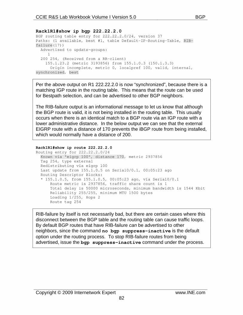
CCIE R&S Lab Workbook Volume I Version 5.0 BGP
Copyright © 2009 Internetwork Expert www.INE.com82
Rack1R1#show ip bgp 222.22.2.0 BGP routing table entry for 222.22.2.0/24, version 37 Paths: (1 available, best #1, table Default-IP-Routing-Table, RIB-failure(17)) Advertised to update-groups: 1 200 254, (Received from a RR-client) 155.1.23.2 (metric 3193856) from 155.1.0.3 (150.1.3.3) Origin incomplete, metric 0, localpref 100, valid, internal, synchronized, best
Per the above output on R1 222.22.2.0 is now “synchronized”, because there is a matching IGP route in the routing table. This means that the route can be used for Bestpath selection, and can be advertised to other BGP neighbors.
The RIB-failure output is an informational message to let us know that although the BGP route is valid, it is not being installed in the routing table. This usually occurs when there is an identical match to a BGP route via an IGP route with a lower administrative distance. In the below output we can see that the external EIGRP route with a distance of 170 prevents the iBGP route from being installed, which would normally have a distance of 200.
Rack1R1#show ip route 222.22.2.0 Routing entry for 222.22.2.0/24 Known via "eigrp 100", distance 170, metric 2937856 Tag 254, type external Redistributing via eigrp 100 Last update from 155.1.0.5 on Serial0/0.1, 00:05:23 ago Routing Descriptor Blocks: * 155.1.0.5, from 155.1.0.5, 00:05:23 ago, via Serial0/0.1 Route metric is 2937856, traffic share count is 1 Total delay is 50000 microseconds, minimum bandwidth is 1544 Kbit Reliability 255/255, minimum MTU 1500 bytes Loading 1/255, Hops 2 Route tag 254
RIB-failure by itself is not necessarily bad, but there are certain cases where this disconnect between the BGP table and the routing table can cause traffic loops. By default BGP routes that have RIB-failure can be advertised to other neighbors, since the command no bgp suppress-inactive is the default option under the routing process. To stop RIB-failure routes from being advertised, issue the bgp suppress-inactive command under the process.
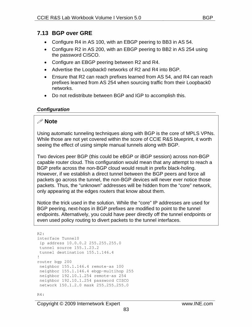
CCIE R&S Lab Workbook Volume I Version 5.0 BGP
Copyright © 2009 Internetwork Expert www.INE.com83
7.13 BGP over GRE • Configure R4 in AS 100, with an EBGP peering to BB3 in AS 54. • Configure R2 in AS 200, with an EBGP peering to BB2 in AS 254 using
the password CISCO. • Configure an EBGP peering between R2 and R4. • Advertise the Loopback0 networks of R2 and R4 into BGP. • Ensure that R2 can reach prefixes learned from AS 54, and R4 can reach
prefixes learned from AS 254 when sourcing traffic from their Loopback0 networks.
• Do not redistribute between BGP and IGP to accomplish this.
Configuration
Note
Using automatic tunneling techniques along with BGP is the core of MPLS VPNs. While those are not yet covered within the score of CCIE R&S blueprint, it worth seeing the effect of using simple manual tunnels along with BGP.
Two devices peer BGP (this could be eBGP or iBGP session) across non-BGP capable router cloud. This configuration would mean that any attempt to reach a BGP prefix across the non-BGP cloud would result in prefix black-holing. However, if we establish a direct tunnel between the BGP peers and force all packets go across the tunnel, the non-BGP devices will never ever notice those packets. Thus, the “unknown” addresses will be hidden from the “core” network, only appearing at the edges routers that know about them.
Notice the trick used in the solution. While the “core” IP addresses are used for BGP peering, next-hops in BGP prefixes are modified to point to the tunnel endpoints. Alternatively, you could have peer directly off the tunnel endpoints or even used policy routing to divert packets to the tunnel interfaces.
R2: interface Tunnel0 ip address 10.0.0.2 255.255.255.0 tunnel source 155.1.23.2 tunnel destination 155.1.146.4 ! router bgp 200 neighbor 155.1.146.4 remote-as 100 neighbor 155.1.146.4 ebgp-multihop 255 neighbor 192.10.1.254 remote-as 254 neighbor 192.10.1.254 password CISCO network 150.1.2.0 mask 255.255.255.0
R4:
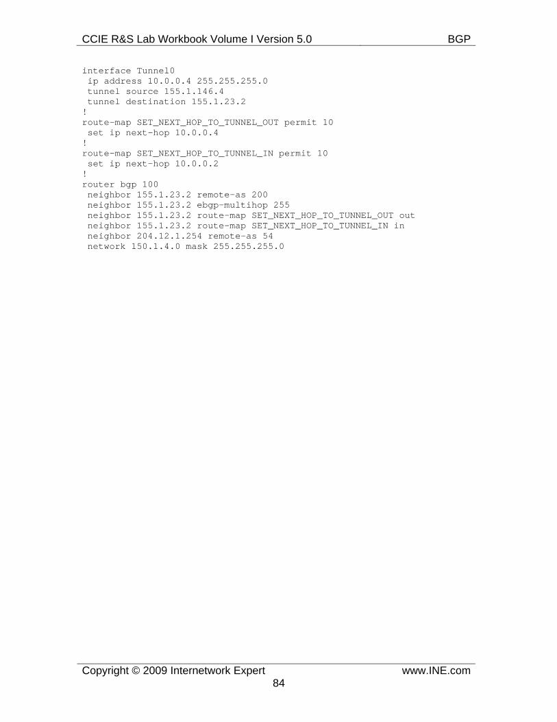
CCIE R&S Lab Workbook Volume I Version 5.0 BGP
Copyright © 2009 Internetwork Expert www.INE.com84
interface Tunnel0 ip address 10.0.0.4 255.255.255.0 tunnel source 155.1.146.4 tunnel destination 155.1.23.2 ! route-map SET_NEXT_HOP_TO_TUNNEL_OUT permit 10 set ip next-hop 10.0.0.4 ! route-map SET_NEXT_HOP_TO_TUNNEL_IN permit 10 set ip next-hop 10.0.0.2 ! router bgp 100 neighbor 155.1.23.2 remote-as 200 neighbor 155.1.23.2 ebgp-multihop 255 neighbor 155.1.23.2 route-map SET_NEXT_HOP_TO_TUNNEL_OUT out neighbor 155.1.23.2 route-map SET_NEXT_HOP_TO_TUNNEL_IN in neighbor 204.12.1.254 remote-as 54 network 150.1.4.0 mask 255.255.255.0
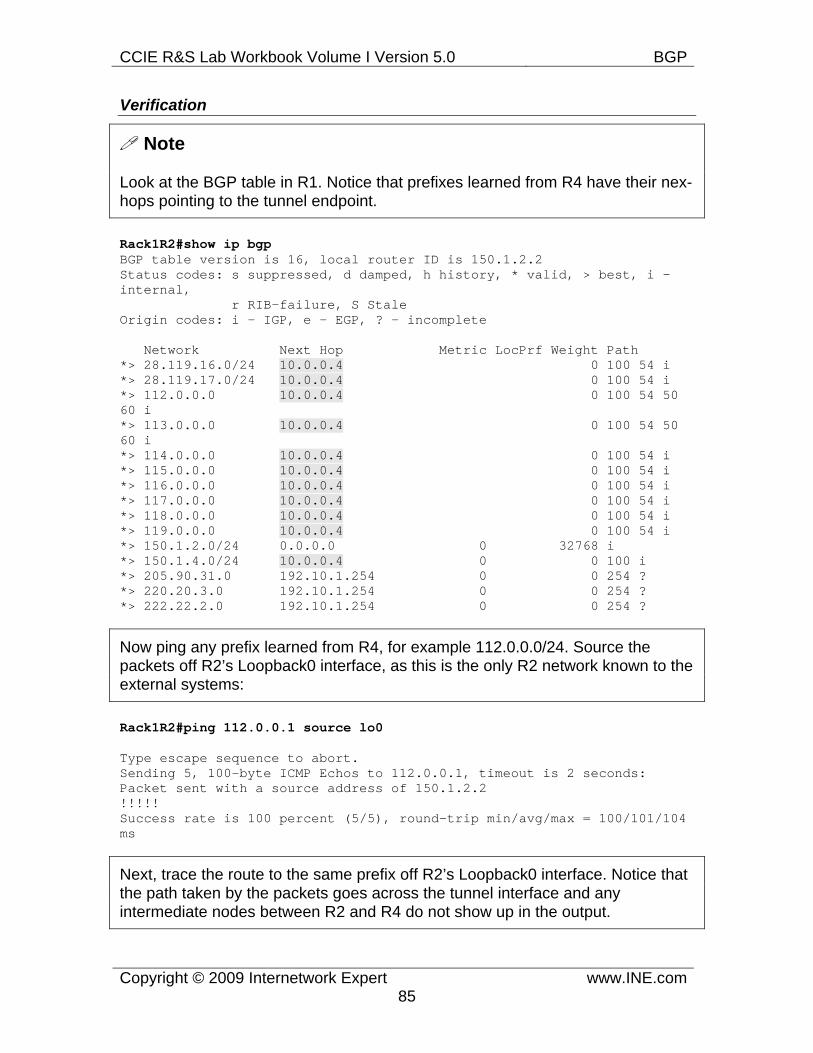
CCIE R&S Lab Workbook Volume I Version 5.0 BGP
Copyright © 2009 Internetwork Expert www.INE.com85
Verification
Note
Look at the BGP table in R1. Notice that prefixes learned from R4 have their nex-hops pointing to the tunnel endpoint.
Rack1R2#show ip bgp BGP table version is 16, local router ID is 150.1.2.2 Status codes: s suppressed, d damped, h history, * valid, > best, i - internal, r RIB-failure, S Stale Origin codes: i - IGP, e - EGP, ? - incomplete
Network Next Hop Metric LocPrf Weight Path *> 28.119.16.0/24 10.0.0.4 0 100 54 i *> 28.119.17.0/24 10.0.0.4 0 100 54 i *> 112.0.0.0 10.0.0.4 0 100 54 50 60 i *> 113.0.0.0 10.0.0.4 0 100 54 50 60 i *> 114.0.0.0 10.0.0.4 0 100 54 i *> 115.0.0.0 10.0.0.4 0 100 54 i *> 116.0.0.0 10.0.0.4 0 100 54 i *> 117.0.0.0 10.0.0.4 0 100 54 i *> 118.0.0.0 10.0.0.4 0 100 54 i *> 119.0.0.0 10.0.0.4 0 100 54 i *> 150.1.2.0/24 0.0.0.0 0 32768 i *> 150.1.4.0/24 10.0.0.4 0 0 100 i *> 205.90.31.0 192.10.1.254 0 0 254 ? *> 220.20.3.0 192.10.1.254 0 0 254 ? *> 222.22.2.0 192.10.1.254 0 0 254 ?
Now ping any prefix learned from R4, for example 112.0.0.0/24. Source the packets off R2’s Loopback0 interface, as this is the only R2 network known to the external systems:
Rack1R2#ping 112.0.0.1 source lo0
Type escape sequence to abort. Sending 5, 100-byte ICMP Echos to 112.0.0.1, timeout is 2 seconds: Packet sent with a source address of 150.1.2.2 !!!!! Success rate is 100 percent (5/5), round-trip min/avg/max = 100/101/104 ms
Next, trace the route to the same prefix off R2’s Loopback0 interface. Notice that the path taken by the packets goes across the tunnel interface and any intermediate nodes between R2 and R4 do not show up in the output.
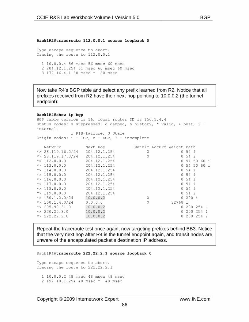
CCIE R&S Lab Workbook Volume I Version 5.0 BGP
Copyright © 2009 Internetwork Expert www.INE.com86
Rack1R2#traceroute 112.0.0.1 source loopback 0
Type escape sequence to abort. Tracing the route to 112.0.0.1
1 10.0.0.4 56 msec 56 msec 60 msec 2 204.12.1.254 61 msec 60 msec 60 msec 3 172.16.4.1 80 msec * 80 msec
Now take R4’s BGP table and select any prefix learned from R2. Notice that all prefixes received from R2 have their next-hop pointing to 10.0.0.2 (the tunnel endpoint):
Rack1R4#show ip bgp BGP table version is 16, local router ID is 150.1.4.4 Status codes: s suppressed, d damped, h history, * valid, > best, i - internal, r RIB-failure, S Stale Origin codes: i - IGP, e - EGP, ? - incomplete
Network Next Hop Metric LocPrf Weight Path *> 28.119.16.0/24 204.12.1.254 0 0 54 i *> 28.119.17.0/24 204.12.1.254 0 0 54 i *> 112.0.0.0 204.12.1.254 0 54 50 60 i *> 113.0.0.0 204.12.1.254 0 54 50 60 i *> 114.0.0.0 204.12.1.254 0 54 i *> 115.0.0.0 204.12.1.254 0 54 i *> 116.0.0.0 204.12.1.254 0 54 i *> 117.0.0.0 204.12.1.254 0 54 i *> 118.0.0.0 204.12.1.254 0 54 i *> 119.0.0.0 204.12.1.254 0 54 i *> 150.1.2.0/24 10.0.0.2 0 0 200 i *> 150.1.4.0/24 0.0.0.0 0 32768 i *> 205.90.31.0 10.0.0.2 0 200 254 ? *> 220.20.3.0 10.0.0.2 0 200 254 ? *> 222.22.2.0 10.0.0.2 0 200 254 ?
Repeat the traceroute test once again, now targeting prefixes behind BB3. Notice that the very next hop after R4 is the tunnel endpoint again, and transit nodes are unware of the encapsulated packet’s destination IP address.
Rack1R4#traceroute 222.22.2.1 source loopback 0
Type escape sequence to abort. Tracing the route to 222.22.2.1
1 10.0.0.2 48 msec 48 msec 48 msec 2 192.10.1.254 48 msec * 48 msec
CCIE R&S Lab Workbook Volume I Version 5.0 BGP
Copyright © 2009 Internetwork Expert www.INE.com87
7.14 BGP Redistribute Internal • Remove all BGP configuration on all devices. • Configure R1, R3, R4, and R6 in AS 100. • R4 and R6 should peer with BB3 and BB1 respectively, who are in AS 54. • R1 should peer with R3, R4, and R6 as a route reflector. • Configure R4 and R6 to advertise the network 155.X.0.0/16 to AS 54. • Configure BGP to IGP redistribution on R3 so that all internal devices
have reachability to the prefixes learned from AS 54.
Configuration
Note
As discussed previously, enabling BGP on all transit devices in the AS is the best way to ensure that all routers have full external routing information. This solution is scalable, as it avoids feeding large BGP tables into IGP.
In some situations, you cannot enable BGP on all routers in your network. This may be the case of an enterprise network, where only border routers peer eBGP with the ISP. In such situations, it is common to advertise a default route from the border routers towards the rest of the network.
There could be even more complicated scenarios, like when you migrating your network or gradually enabling BGP on all devices. In situations like these, you may find that iBGP peers are separated by non-BGP cloud or that non-BGP speakers need BGP routes from the devices that leaned them via iBGP (no eBGP!). So what’s wrong with redistributing iBGP prefixes into IGP? As you remember, BGP uses AS_PATH attributes to detect routing loops. When exchanging iBGP routes, AS_PATH attributes are not prepended and thus the route loop prevention technique does not work. Because of that, feeding iBGP prefixes into an IGP may result in routing loops, as the “split-horizon” rules for BGP prefixes may be broken. To make this situation even worse, iBGP has the AD value that makes it less preferred than any IGP. Thus, iBGP prefixes redistributed into an IGP may preempt iBGP learned prefixes on other iBGP speakers.
To prevent the above mentioned issues, iBGP learned prefixes are not automatically redistributed into IGP when you issue the statement redistribute bgp under any IGP process on the router – only eBGP prefixes are propagated. In order to make iBGP redistribution possible, you need an additional statement configured under the BGP process: bgp redistribute internal. Be very careful when enabling this feature, as you may quickly end up with routing loops, and try avoiding multiple points of iBGP to IGP
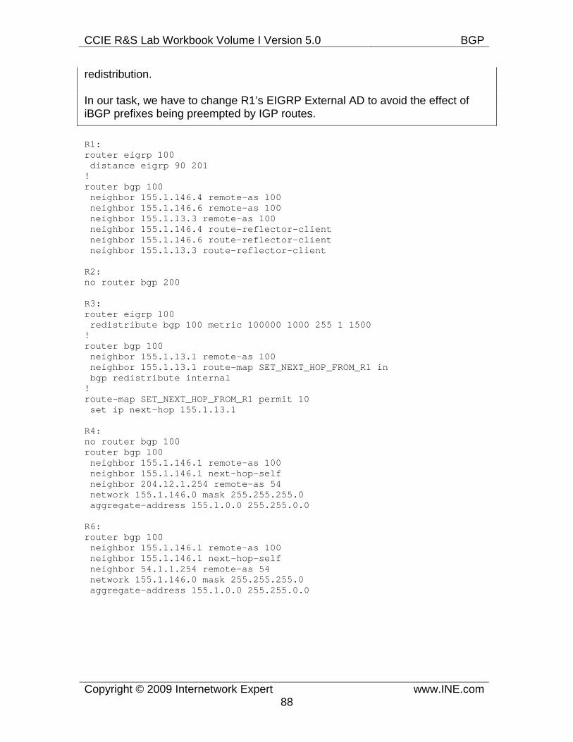
CCIE R&S Lab Workbook Volume I Version 5.0 BGP
Copyright © 2009 Internetwork Expert www.INE.com88
redistribution.
In our task, we have to change R1’s EIGRP External AD to avoid the effect of iBGP prefixes being preempted by IGP routes.
R1: router eigrp 100 distance eigrp 90 201 ! router bgp 100 neighbor 155.1.146.4 remote-as 100 neighbor 155.1.146.6 remote-as 100 neighbor 155.1.13.3 remote-as 100 neighbor 155.1.146.4 route-reflector-client neighbor 155.1.146.6 route-reflector-client neighbor 155.1.13.3 route-reflector-client
R2: no router bgp 200
R3: router eigrp 100 redistribute bgp 100 metric 100000 1000 255 1 1500 ! router bgp 100 neighbor 155.1.13.1 remote-as 100 neighbor 155.1.13.1 route-map SET_NEXT_HOP_FROM_R1 in bgp redistribute internal ! route-map SET_NEXT_HOP_FROM_R1 permit 10 set ip next-hop 155.1.13.1
R4: no router bgp 100 router bgp 100 neighbor 155.1.146.1 remote-as 100 neighbor 155.1.146.1 next-hop-self neighbor 204.12.1.254 remote-as 54 network 155.1.146.0 mask 255.255.255.0 aggregate-address 155.1.0.0 255.255.0.0
R6: router bgp 100 neighbor 155.1.146.1 remote-as 100 neighbor 155.1.146.1 next-hop-self neighbor 54.1.1.254 remote-as 54 network 155.1.146.0 mask 255.255.255.0 aggregate-address 155.1.0.0 255.255.0.0
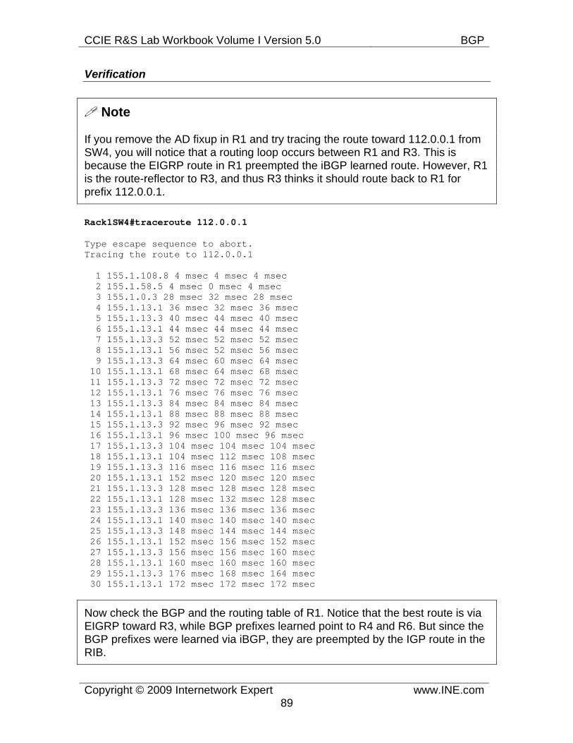
CCIE R&S Lab Workbook Volume I Version 5.0 BGP
Copyright © 2009 Internetwork Expert www.INE.com89
Verification
Note
If you remove the AD fixup in R1 and try tracing the route toward 112.0.0.1 from SW4, you will notice that a routing loop occurs between R1 and R3. This is because the EIGRP route in R1 preempted the iBGP learned route. However, R1 is the route-reflector to R3, and thus R3 thinks it should route back to R1 for prefix 112.0.0.1.
Rack1SW4#traceroute 112.0.0.1
Type escape sequence to abort. Tracing the route to 112.0.0.1
1 155.1.108.8 4 msec 4 msec 4 msec 2 155.1.58.5 4 msec 0 msec 4 msec 3 155.1.0.3 28 msec 32 msec 28 msec 4 155.1.13.1 36 msec 32 msec 36 msec 5 155.1.13.3 40 msec 44 msec 40 msec 6 155.1.13.1 44 msec 44 msec 44 msec 7 155.1.13.3 52 msec 52 msec 52 msec 8 155.1.13.1 56 msec 52 msec 56 msec 9 155.1.13.3 64 msec 60 msec 64 msec 10 155.1.13.1 68 msec 64 msec 68 msec 11 155.1.13.3 72 msec 72 msec 72 msec 12 155.1.13.1 76 msec 76 msec 76 msec 13 155.1.13.3 84 msec 84 msec 84 msec 14 155.1.13.1 88 msec 88 msec 88 msec 15 155.1.13.3 92 msec 96 msec 92 msec 16 155.1.13.1 96 msec 100 msec 96 msec 17 155.1.13.3 104 msec 104 msec 104 msec 18 155.1.13.1 104 msec 112 msec 108 msec 19 155.1.13.3 116 msec 116 msec 116 msec 20 155.1.13.1 152 msec 120 msec 120 msec 21 155.1.13.3 128 msec 128 msec 128 msec 22 155.1.13.1 128 msec 132 msec 128 msec 23 155.1.13.3 136 msec 136 msec 136 msec 24 155.1.13.1 140 msec 140 msec 140 msec 25 155.1.13.3 148 msec 144 msec 144 msec 26 155.1.13.1 152 msec 156 msec 152 msec 27 155.1.13.3 156 msec 156 msec 160 msec 28 155.1.13.1 160 msec 160 msec 160 msec 29 155.1.13.3 176 msec 168 msec 164 msec 30 155.1.13.1 172 msec 172 msec 172 msec
Now check the BGP and the routing table of R1. Notice that the best route is via EIGRP toward R3, while BGP prefixes learned point to R4 and R6. But since the BGP prefixes were learned via iBGP, they are preempted by the IGP route in the RIB.
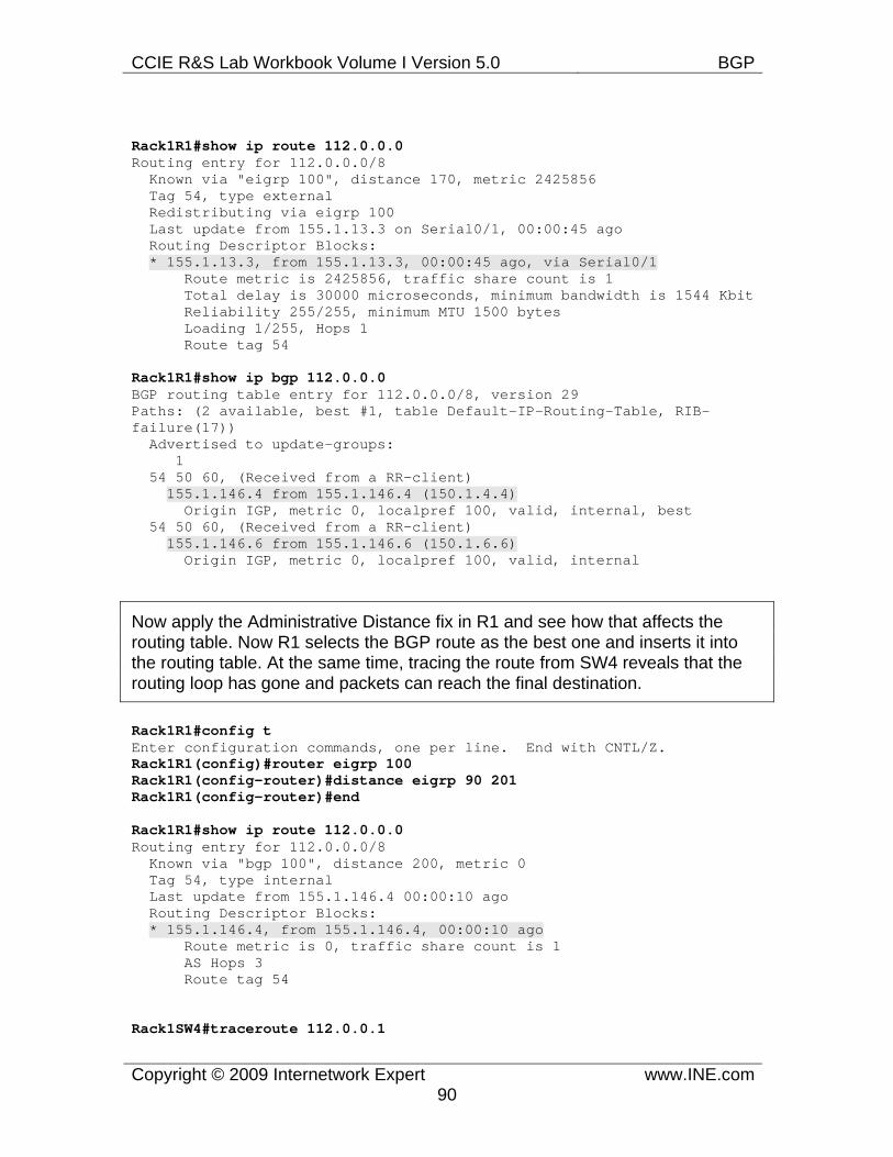
CCIE R&S Lab Workbook Volume I Version 5.0 BGP
Copyright © 2009 Internetwork Expert www.INE.com90
Rack1R1#show ip route 112.0.0.0 Routing entry for 112.0.0.0/8 Known via "eigrp 100", distance 170, metric 2425856 Tag 54, type external Redistributing via eigrp 100 Last update from 155.1.13.3 on Serial0/1, 00:00:45 ago Routing Descriptor Blocks: * 155.1.13.3, from 155.1.13.3, 00:00:45 ago, via Serial0/1 Route metric is 2425856, traffic share count is 1 Total delay is 30000 microseconds, minimum bandwidth is 1544 Kbit Reliability 255/255, minimum MTU 1500 bytes Loading 1/255, Hops 1 Route tag 54
Rack1R1#show ip bgp 112.0.0.0 BGP routing table entry for 112.0.0.0/8, version 29 Paths: (2 available, best #1, table Default-IP-Routing-Table, RIB-failure(17)) Advertised to update-groups: 1 54 50 60, (Received from a RR-client) 155.1.146.4 from 155.1.146.4 (150.1.4.4) Origin IGP, metric 0, localpref 100, valid, internal, best 54 50 60, (Received from a RR-client) 155.1.146.6 from 155.1.146.6 (150.1.6.6) Origin IGP, metric 0, localpref 100, valid, internal
Now apply the Administrative Distance fix in R1 and see how that affects the routing table. Now R1 selects the BGP route as the best one and inserts it into the routing table. At the same time, tracing the route from SW4 reveals that the routing loop has gone and packets can reach the final destination.
Rack1R1#config t Enter configuration commands, one per line. End with CNTL/Z. Rack1R1(config)#router eigrp 100 Rack1R1(config-router)#distance eigrp 90 201 Rack1R1(config-router)#end
Rack1R1#show ip route 112.0.0.0 Routing entry for 112.0.0.0/8 Known via "bgp 100", distance 200, metric 0 Tag 54, type internal Last update from 155.1.146.4 00:00:10 ago Routing Descriptor Blocks: * 155.1.146.4, from 155.1.146.4, 00:00:10 ago Route metric is 0, traffic share count is 1 AS Hops 3 Route tag 54
Rack1SW4#traceroute 112.0.0.1
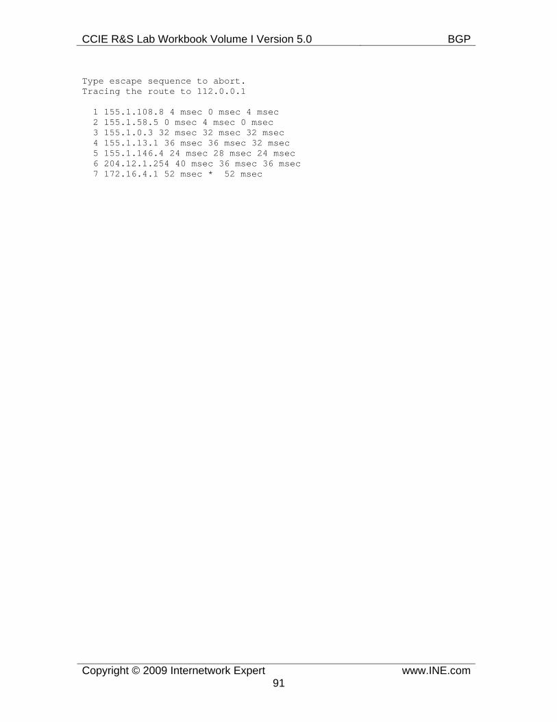
CCIE R&S Lab Workbook Volume I Version 5.0 BGP
Copyright © 2009 Internetwork Expert www.INE.com91
Type escape sequence to abort. Tracing the route to 112.0.0.1
1 155.1.108.8 4 msec 0 msec 4 msec 2 155.1.58.5 0 msec 4 msec 0 msec 3 155.1.0.3 32 msec 32 msec 32 msec 4 155.1.13.1 36 msec 36 msec 32 msec 5 155.1.146.4 24 msec 28 msec 24 msec 6 204.12.1.254 40 msec 36 msec 36 msec 7 172.16.4.1 52 msec * 52 msec
CCIE R&S Lab Workbook Volume I Version 5.0 BGP
Copyright © 2009 Internetwork Expert www.INE.com92
7.15 BGP Peer Groups
• Remove all BGP the configuration on the devices in AS 100. • Configure BGP on all internal devices, with the exception of R2 and all
switches, using AS 100. • Configure iBGP peerings from R1 to all other devices in AS 100 using the
peer group named IBGP_PEERS. • Configure EBGP peerings between R4 & BB3 and R6 & BB1 using their
directly connected links; BB1 and BB3 are in AS 54. • Advertise the Loopback0 interfaces of all devices into BGP. • Ensure full reachability to the Loopback0 interfaces from all internal
devices, and to all prefixes learned from AS 54 and AS 254 from all internal devices when sourcing traffic from the Loopback0 interfaces.
Configuration
Note
Large-scale BGP deployments often implement hundreds of BGP peers for a single router. The high amount of peers poses certain scalability issues, to name a few:
1) Configuration burden becomes to intense to deal with and is error-prone. 2) Numerous BGP peers require the router CPU to prepare, batch and replicate BGP updates (often hundred of thousands prefixes) individually for each peer. This poses great stress on router’s CPUs.
BGP Peer groups try to overcome the above two issues by utilizing the fact that often many peers have similar BGP policy configuration. For example they all have the same remote AS, outgoing route filters, route-reflection-properties and so on. Based on this fact, many BGP peers sharing the same outgoing policy could be aggregated into a single BGP peer group. The peer group is essentially a template that specifies a particular BGP policy. You create a peer group using the command neighbor <PEER_GROUP_TAG> peer-group and then applying all BGP settings to the named tag like if it was a regular BGP peer. When you’re done with the peer-group configuration, you assign BGP peers to the group using the command neighbor <IP_Address> peer-group <PEER_GROUP_TAG>.
The router’s CPU usage is highly optimized when using the peer-groups. All members of the peer group share the same policy, thus allowing a batch of BGP prefixes to be prepared just once, before relayed to all peer-group member. However, this optimization process means that you cannot tune outgoing BGP
CCIE R&S Lab Workbook Volume I Version 5.0 BGP
Copyright © 2009 Internetwork Expert www.INE.com93
settings for every member of a peer group individually. For example, you cannot apply a different outgoing route-map to the neighbor that is a member of a BGP peer group. However, you are free to change any incoming policy settings, such as inbound filters.
R1: router bgp 100 neighbor IBGP_PEERS peer-group neighbor IBGP_PEERS remote-as 100 neighbor IBGP_PEERS update-source Loopback0 neighbor IBGP_PEERS route-reflector-client neighbor 150.1.4.4 peer-group IBGP_PEERS neighbor 150.1.3.3 peer-group IBGP_PEERS neighbor 150.1.5.5 peer-group IBGP_PEERS neighbor 150.1.6.6 peer-group IBGP_PEERS network 150.1.1.0 mask 255.255.255.0 ! router eigrp 100 network 150.1.1.1 0.0.0.0
R3: router bgp 100 neighbor 150.1.1.1 remote-as 100 neighbor 150.1.1.1 update-source Loopback0 network 150.1.3.0 mask 255.255.255.0 ! router eigrp 100 network 150.1.3.3 0.0.0.0
R4: router bgp 100 neighbor 150.1.1.1 remote-as 100 neighbor 150.1.1.1 update-source Loopback0 neighbor 150.1.1.1 next-hop-self neighbor 204.12.1.254 remote-as 54 network 150.1.4.0 mask 255.255.255.0 ! router eigrp 100 network 150.1.4.4 0.0.0.0
R5: router bgp 100 neighbor 150.1.1.1 remote-as 100 neighbor 150.1.1.1 update-source Loopback0 network 150.1.5.0 mask 255.255.255.0 ! router eigrp 100 network 150.1.5.5 0.0.0.0
R6: router bgp 100 neighbor 150.1.1.1 remote-as 100 neighbor 150.1.1.1 update-source Loopback0 Neighbor 150.1.1.1 next-hop-self
CCIE R&S Lab Workbook Volume I Version 5.0 BGP
Copyright © 2009 Internetwork Expert www.INE.com94
neighbor 54.1.1.254 remote-as 54 network 150.1.6.0 mask 255.255.255.0 ! router eigrp 100 network 150.1.6.6 0.0.0.0
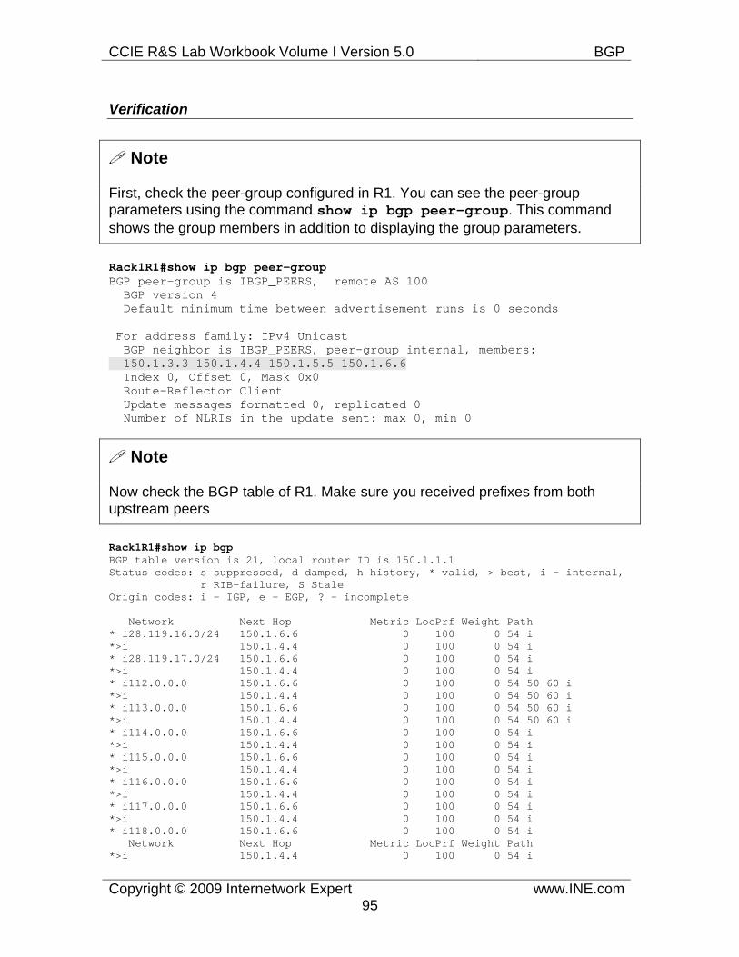
CCIE R&S Lab Workbook Volume I Version 5.0 BGP
Copyright © 2009 Internetwork Expert www.INE.com95
Verification
Note
First, check the peer-group configured in R1. You can see the peer-group parameters using the command show ip bgp peer-group. This command shows the group members in addition to displaying the group parameters.
Rack1R1#show ip bgp peer-group BGP peer-group is IBGP_PEERS, remote AS 100 BGP version 4 Default minimum time between advertisement runs is 0 seconds
For address family: IPv4 Unicast BGP neighbor is IBGP_PEERS, peer-group internal, members: 150.1.3.3 150.1.4.4 150.1.5.5 150.1.6.6 Index 0, Offset 0, Mask 0x0 Route-Reflector Client Update messages formatted 0, replicated 0 Number of NLRIs in the update sent: max 0, min 0
Note
Now check the BGP table of R1. Make sure you received prefixes from both upstream peers
Rack1R1#show ip bgp BGP table version is 21, local router ID is 150.1.1.1 Status codes: s suppressed, d damped, h history, * valid, > best, i - internal, r RIB-failure, S Stale Origin codes: i - IGP, e - EGP, ? - incomplete
Network Next Hop Metric LocPrf Weight Path * i28.119.16.0/24 150.1.6.6 0 100 0 54 i *>i 150.1.4.4 0 100 0 54 i * i28.119.17.0/24 150.1.6.6 0 100 0 54 i *>i 150.1.4.4 0 100 0 54 i * i112.0.0.0 150.1.6.6 0 100 0 54 50 60 i *>i 150.1.4.4 0 100 0 54 50 60 i * i113.0.0.0 150.1.6.6 0 100 0 54 50 60 i *>i 150.1.4.4 0 100 0 54 50 60 i * i114.0.0.0 150.1.6.6 0 100 0 54 i *>i 150.1.4.4 0 100 0 54 i * i115.0.0.0 150.1.6.6 0 100 0 54 i *>i 150.1.4.4 0 100 0 54 i * i116.0.0.0 150.1.6.6 0 100 0 54 i *>i 150.1.4.4 0 100 0 54 i * i117.0.0.0 150.1.6.6 0 100 0 54 i *>i 150.1.4.4 0 100 0 54 i * i118.0.0.0 150.1.6.6 0 100 0 54 i Network Next Hop Metric LocPrf Weight Path *>i 150.1.4.4 0 100 0 54 i
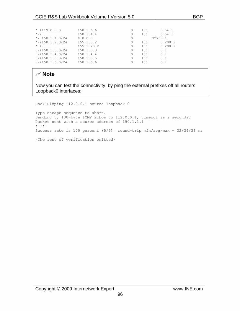
CCIE R&S Lab Workbook Volume I Version 5.0 BGP
Copyright © 2009 Internetwork Expert www.INE.com96
* i119.0.0.0 150.1.6.6 0 100 0 54 i *>i 150.1.4.4 0 100 0 54 i *> 150.1.1.0/24 0.0.0.0 0 32768 i *>i150.1.2.0/24 155.1.0.2 0 100 0 200 i * i 155.1.23.2 0 100 0 200 i r>i150.1.3.0/24 150.1.3.3 0 100 0 i r>i150.1.4.0/24 150.1.4.4 0 100 0 i r>i150.1.5.0/24 150.1.5.5 0 100 0 i r>i150.1.6.0/24 150.1.6.6 0 100 0 i
Note
Now you can test the connectivity, by ping the external prefixes off all routers’ Loopback0 interfaces:
Rack1R1#ping 112.0.0.1 source loopback 0
Type escape sequence to abort. Sending 5, 100-byte ICMP Echos to 112.0.0.1, timeout is 2 seconds: Packet sent with a source address of 150.1.1.1 !!!!! Success rate is 100 percent (5/5), round-trip min/avg/max = 32/34/36 ms
<The rest of verification omitted>
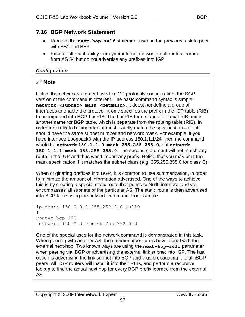
CCIE R&S Lab Workbook Volume I Version 5.0 BGP
Copyright © 2009 Internetwork Expert www.INE.com97
7.16 BGP Network Statement • Remove the next-hop-self statement used in the previous task to peer
with BB1 and BB3 • Ensure full reachability from your internal network to all routes learned
from AS 54 but do not advertise any prefixes into IGP
Configuration
Note
Unlike the network statement used in IGP protocols configuration, the BGP version of the command is different. The basic command syntax is simple: network <subnet> mask <netmask>. It doest not define a group of interfaces to enable the protocol, it only specifies the prefix in the IGP table (RIB) to be imported into BGP LocRIB. The LocRIB term stands for Local RIB and is another name for BGP table, which is separate from the routing table (RIB). In order for prefix to be imported, it must exactly match the specification – i.e. it should have the same subnet number and network mask. For example, if you have interface Loopback0 with the IP address 150.1.1.1/24, then the command would be network 150.1.1.0 mask 255.255.255.0, not network 150.1.1.1 mask 255.255.255.0. The second statement will not match any route in the IGP and thus won’t import any prefix. Notice that you may omit the mask specification if it matches the subnet class (e.g. 255.255.255.0 for class C).
When originating prefixes into BGP, it is common to use summarization, in order to minimize the amount of information advertised. One of the ways to achieve this is by creating a special static route that points to Null0 interface and yet encompasses all subnets of the particular AS. The static route is then advertised into BGP table using the network command. For example:
ip route 150.0.0.0 255.252.0.0 Null0 ! router bgp 100 network 150.0.0.0 mask 255.252.0.0
One of the special uses for the network command is demonstrated in this task. When peering with another AS, the common question is how to deal with the external next-hop. Two known ways are using the next-hop-self parameter when peering via iBGP or advertising the external link subnet into IGP. The last option is advertising the link subnet into BGP and thus propagating it to all iBGP peers. All BGP routers will install it into their RIBs, and perform a recursive lookup to find the actual next hop for every BGP prefix learned from the external AS.
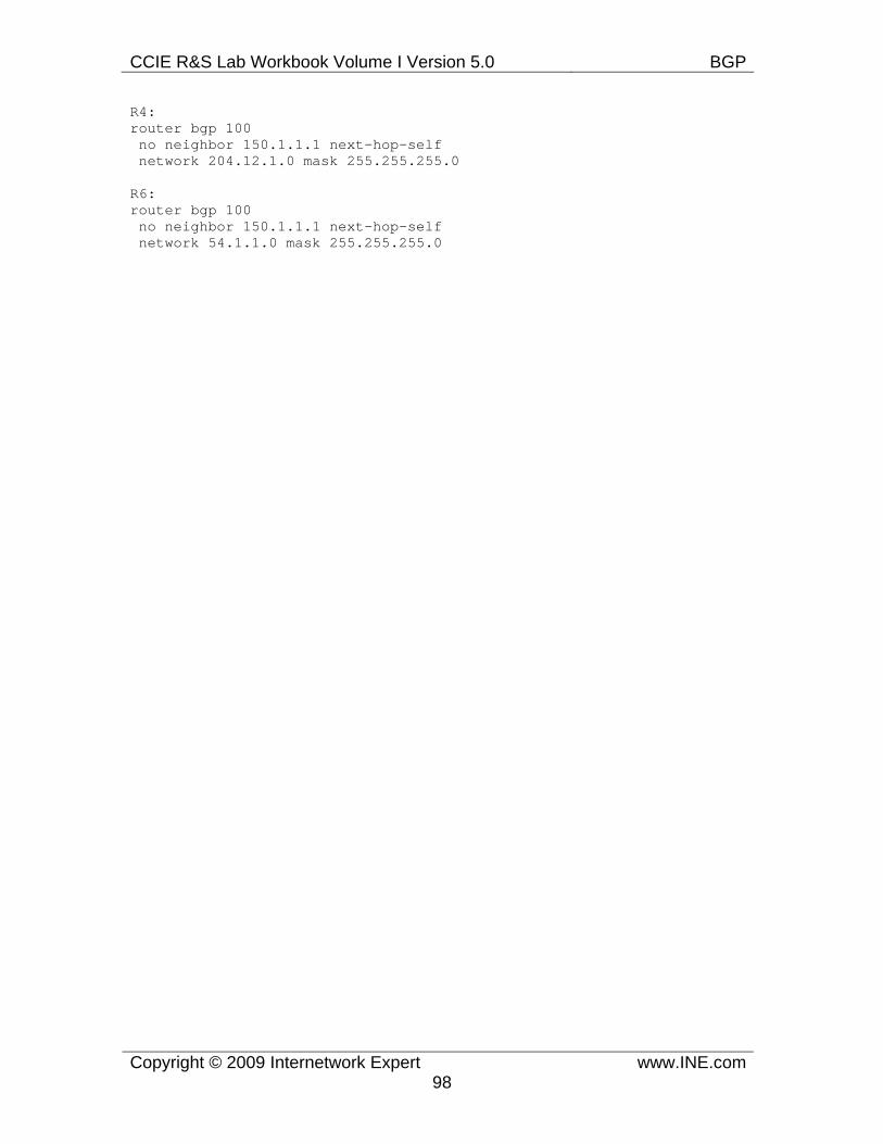
CCIE R&S Lab Workbook Volume I Version 5.0 BGP
Copyright © 2009 Internetwork Expert www.INE.com98
R4: router bgp 100 no neighbor 150.1.1.1 next-hop-self network 204.12.1.0 mask 255.255.255.0
R6: router bgp 100 no neighbor 150.1.1.1 next-hop-self network 54.1.1.0 mask 255.255.255.0
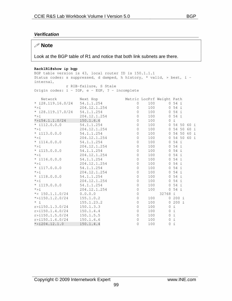
CCIE R&S Lab Workbook Volume I Version 5.0 BGP
Copyright © 2009 Internetwork Expert www.INE.com99
Verification
Note
Look at the BGP table of R1 and notice that both link subnets are there.
Rack1R1#show ip bgp BGP table version is 43, local router ID is 150.1.1.1 Status codes: s suppressed, d damped, h history, * valid, > best, i - internal, r RIB-failure, S Stale Origin codes: i - IGP, e - EGP, ? - incomplete
Network Next Hop Metric LocPrf Weight Path * i28.119.16.0/24 54.1.1.254 0 100 0 54 i *>i 204.12.1.254 0 100 0 54 i * i28.119.17.0/24 54.1.1.254 0 100 0 54 i *>i 204.12.1.254 0 100 0 54 i *>i54.1.1.0/24 150.1.6.6 0 100 0 i * i112.0.0.0 54.1.1.254 0 100 0 54 50 60 i *>i 204.12.1.254 0 100 0 54 50 60 i * i113.0.0.0 54.1.1.254 0 100 0 54 50 60 i *>i 204.12.1.254 0 100 0 54 50 60 i * i114.0.0.0 54.1.1.254 0 100 0 54 i *>i 204.12.1.254 0 100 0 54 i * i115.0.0.0 54.1.1.254 0 100 0 54 i *>i 204.12.1.254 0 100 0 54 i * i116.0.0.0 54.1.1.254 0 100 0 54 i *>i 204.12.1.254 0 100 0 54 i * i117.0.0.0 54.1.1.254 0 100 0 54 i *>i 204.12.1.254 0 100 0 54 i * i118.0.0.0 54.1.1.254 0 100 0 54 i *>i 204.12.1.254 0 100 0 54 i * i119.0.0.0 54.1.1.254 0 100 0 54 i *>i 204.12.1.254 0 100 0 54 i *> 150.1.1.0/24 0.0.0.0 0 32768 i *>i150.1.2.0/24 155.1.0.2 0 100 0 200 i * i 155.1.23.2 0 100 0 200 i r>i150.1.3.0/24 150.1.3.3 0 100 0 i r>i150.1.4.0/24 150.1.4.4 0 100 0 i r>i150.1.5.0/24 150.1.5.5 0 100 0 i r>i150.1.6.0/24 150.1.6.6 0 100 0 i *>i204.12.1.0 150.1.4.4 0 100 0 i
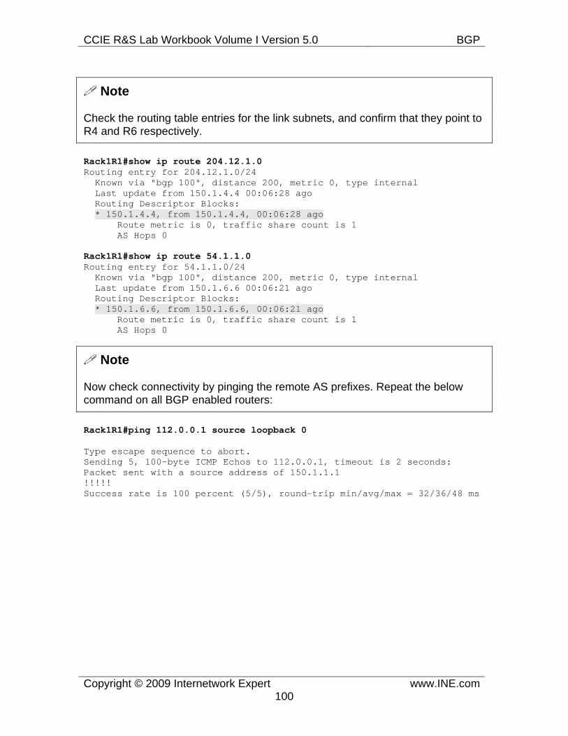
CCIE R&S Lab Workbook Volume I Version 5.0 BGP
Copyright © 2009 Internetwork Expert www.INE.com100
Note
Check the routing table entries for the link subnets, and confirm that they point to R4 and R6 respectively.
Rack1R1#show ip route 204.12.1.0 Routing entry for 204.12.1.0/24 Known via "bgp 100", distance 200, metric 0, type internal Last update from 150.1.4.4 00:06:28 ago Routing Descriptor Blocks: * 150.1.4.4, from 150.1.4.4, 00:06:28 ago Route metric is 0, traffic share count is 1 AS Hops 0
Rack1R1#show ip route 54.1.1.0 Routing entry for 54.1.1.0/24 Known via "bgp 100", distance 200, metric 0, type internal Last update from 150.1.6.6 00:06:21 ago Routing Descriptor Blocks: * 150.1.6.6, from 150.1.6.6, 00:06:21 ago Route metric is 0, traffic share count is 1 AS Hops 0
Note
Now check connectivity by pinging the remote AS prefixes. Repeat the below command on all BGP enabled routers:
Rack1R1#ping 112.0.0.1 source loopback 0
Type escape sequence to abort. Sending 5, 100-byte ICMP Echos to 112.0.0.1, timeout is 2 seconds: Packet sent with a source address of 150.1.1.1 !!!!! Success rate is 100 percent (5/5), round-trip min/avg/max = 32/36/48 ms
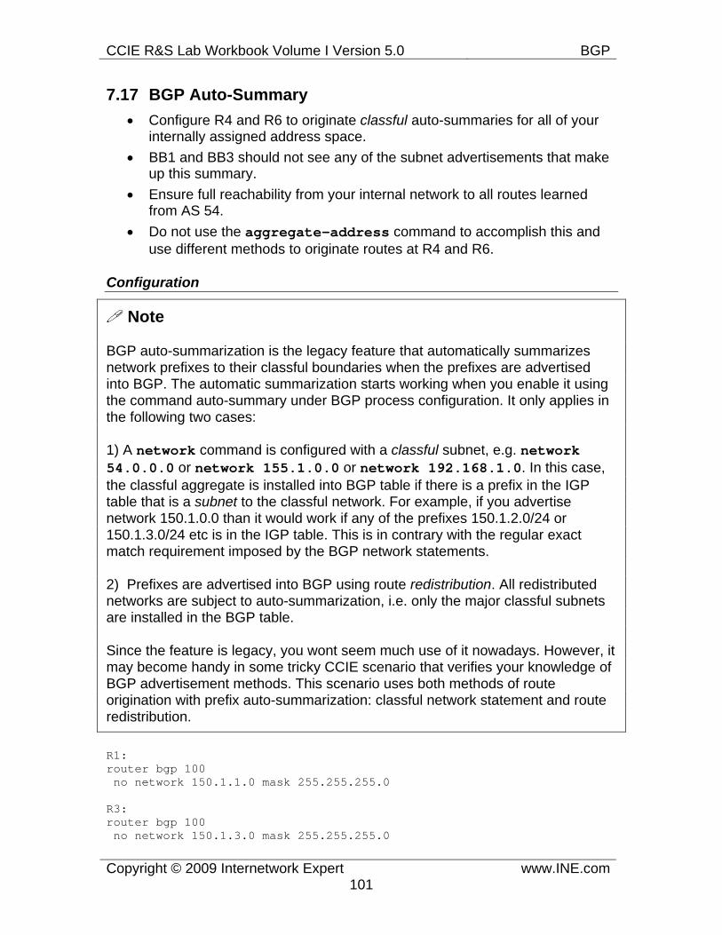
CCIE R&S Lab Workbook Volume I Version 5.0 BGP
Copyright © 2009 Internetwork Expert www.INE.com101
7.17 BGP Auto-Summary • Configure R4 and R6 to originate classful auto-summaries for all of your
internally assigned address space. • BB1 and BB3 should not see any of the subnet advertisements that make
up this summary. • Ensure full reachability from your internal network to all routes learned
from AS 54. • Do not use the aggregate-address command to accomplish this and
use different methods to originate routes at R4 and R6.
Configuration
Note
BGP auto-summarization is the legacy feature that automatically summarizes network prefixes to their classful boundaries when the prefixes are advertised into BGP. The automatic summarization starts working when you enable it using the command auto-summary under BGP process configuration. It only applies in the following two cases:
1) A network command is configured with a classful subnet, e.g. network 54.0.0.0 or network 155.1.0.0 or network 192.168.1.0. In this case, the classful aggregate is installed into BGP table if there is a prefix in the IGP table that is a subnet to the classful network. For example, if you advertise network 150.1.0.0 than it would work if any of the prefixes 150.1.2.0/24 or 150.1.3.0/24 etc is in the IGP table. This is in contrary with the regular exact match requirement imposed by the BGP network statements.
2) Prefixes are advertised into BGP using route redistribution. All redistributed networks are subject to auto-summarization, i.e. only the major classful subnets are installed in the BGP table.
Since the feature is legacy, you wont seem much use of it nowadays. However, it may become handy in some tricky CCIE scenario that verifies your knowledge of BGP advertisement methods. This scenario uses both methods of route origination with prefix auto-summarization: classful network statement and route redistribution.
R1: router bgp 100 no network 150.1.1.0 mask 255.255.255.0
R3: router bgp 100 no network 150.1.3.0 mask 255.255.255.0
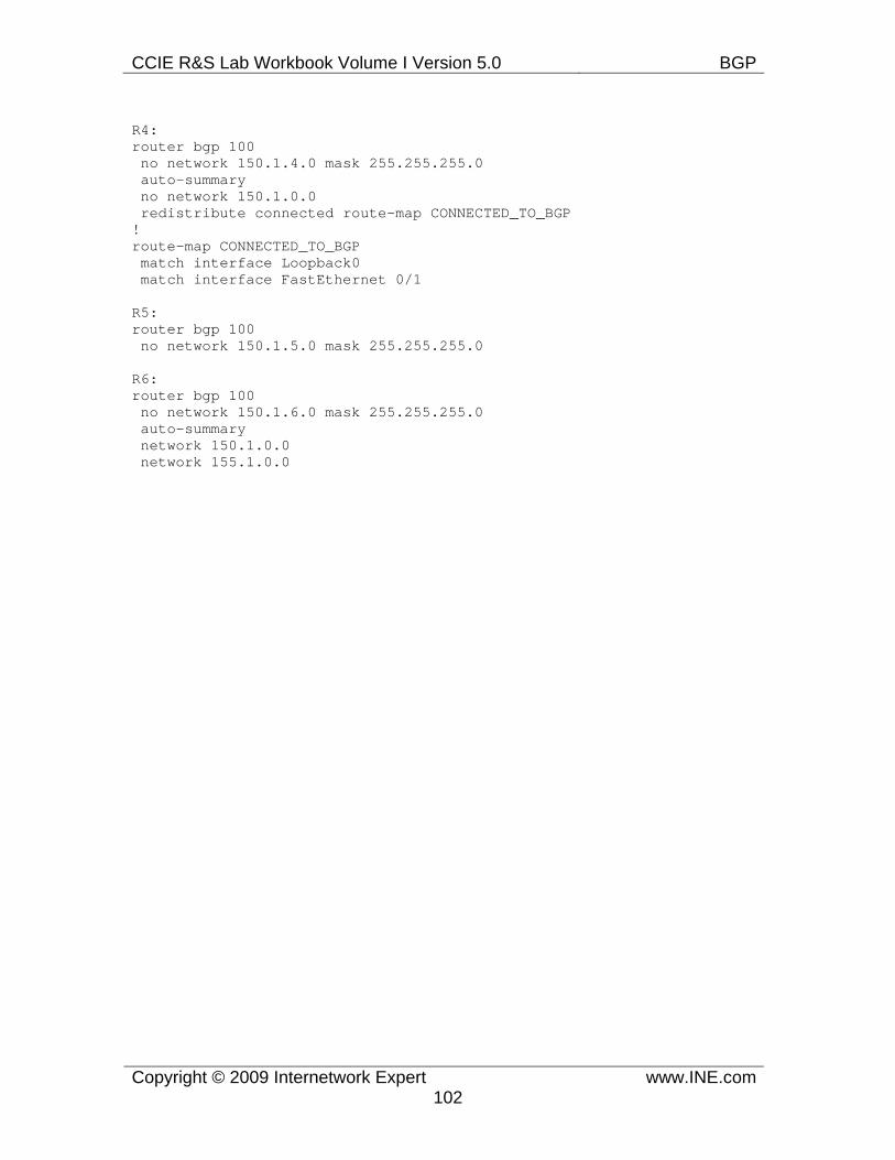
CCIE R&S Lab Workbook Volume I Version 5.0 BGP
Copyright © 2009 Internetwork Expert www.INE.com102
R4: router bgp 100 no network 150.1.4.0 mask 255.255.255.0 auto-summary no network 150.1.0.0 redistribute connected route-map CONNECTED_TO_BGP ! route-map CONNECTED_TO_BGP match interface Loopback0 match interface FastEthernet 0/1
R5: router bgp 100 no network 150.1.5.0 mask 255.255.255.0
R6: router bgp 100 no network 150.1.6.0 mask 255.255.255.0 auto-summary network 150.1.0.0 network 155.1.0.0
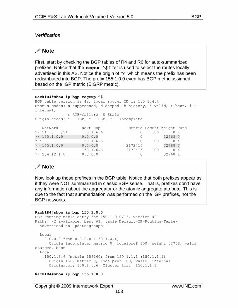
CCIE R&S Lab Workbook Volume I Version 5.0 BGP
Copyright © 2009 Internetwork Expert www.INE.com103
Verification
Note
First, start by checking the BGP tables of R4 and R6 for auto-summarized prefixes. Notice that the regex ^$ filter is used to select the routes locally advertised in this AS. Notice the origin of “?” which means the prefix has been redistributed into BGP. The prefix 155.1.0.0 even has BGP metric assigned based on the IGP metric (EIGRP metric).
Rack1R4#show ip bgp regexp ^$ BGP table version is 42, local router ID is 150.1.4.4 Status codes: s suppressed, d damped, h history, * valid, > best, i - internal, r RIB-failure, S Stale Origin codes: i - IGP, e - EGP, ? - incomplete
Network Next Hop Metric LocPrf Weight Path *>i54.1.1.0/24 150.1.6.6 0 100 0 i *> 150.1.0.0 0.0.0.0 0 32768 ? * i 150.1.6.6 0 100 0 i *> 155.1.0.0 0.0.0.0 2172416 32768 ? * i 150.1.6.6 2172416 100 0 i *> 204.12.1.0 0.0.0.0 0 32768 i
Note
Now look up those prefixes in the BGP table. Notice that both prefixes appear as if they were NOT summarized in classic BGP sense. That is, prefixes don’t have any information about the aggregator or the atomic aggregate attribute. This is due to the fact that summarization was performed on the IGP prefixes, not the BGP networks.
Rack1R4#show ip bgp 150.1.0.0 BGP routing table entry for 150.1.0.0/16, version 42 Paths: (2 available, best #1, table Default-IP-Routing-Table) Advertised to update-groups: 1 2 Local 0.0.0.0 from 0.0.0.0 (150.1.4.4) Origin incomplete, metric 0, localpref 100, weight 32768, valid, sourced, best Local 150.1.6.6 (metric 156160) from 150.1.1.1 (150.1.1.1) Origin IGP, metric 0, localpref 100, valid, internal Originator: 150.1.6.6, Cluster list: 150.1.1.1
Rack1R4#show ip bgp 155.1.0.0
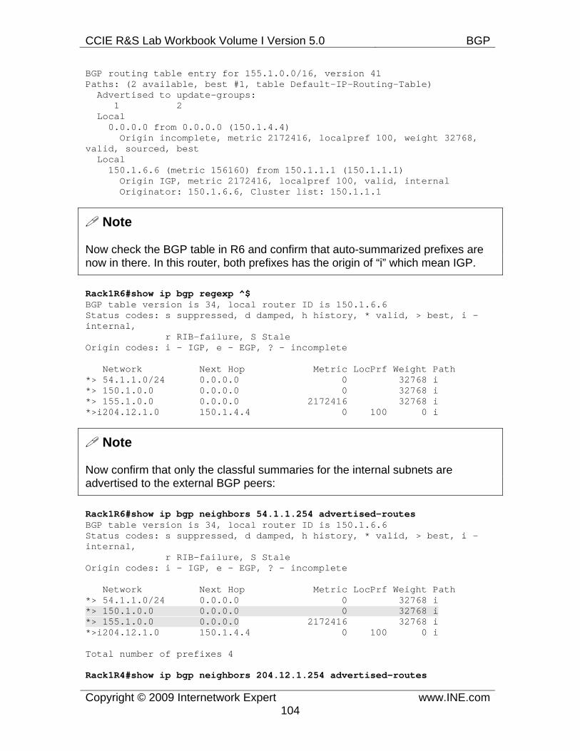
CCIE R&S Lab Workbook Volume I Version 5.0 BGP
Copyright © 2009 Internetwork Expert www.INE.com104
BGP routing table entry for 155.1.0.0/16, version 41 Paths: (2 available, best #1, table Default-IP-Routing-Table) Advertised to update-groups: 1 2 Local 0.0.0.0 from 0.0.0.0 (150.1.4.4) Origin incomplete, metric 2172416, localpref 100, weight 32768, valid, sourced, best Local 150.1.6.6 (metric 156160) from 150.1.1.1 (150.1.1.1) Origin IGP, metric 2172416, localpref 100, valid, internal Originator: 150.1.6.6, Cluster list: 150.1.1.1
Note
Now check the BGP table in R6 and confirm that auto-summarized prefixes are now in there. In this router, both prefixes has the origin of “i” which mean IGP.
Rack1R6#show ip bgp regexp ^$ BGP table version is 34, local router ID is 150.1.6.6 Status codes: s suppressed, d damped, h history, * valid, > best, i - internal, r RIB-failure, S Stale Origin codes: i - IGP, e - EGP, ? - incomplete
Network Next Hop Metric LocPrf Weight Path *> 54.1.1.0/24 0.0.0.0 0 32768 i *> 150.1.0.0 0.0.0.0 0 32768 i *> 155.1.0.0 0.0.0.0 2172416 32768 i *>i204.12.1.0 150.1.4.4 0 100 0 i
Note
Now confirm that only the classful summaries for the internal subnets are advertised to the external BGP peers:
Rack1R6#show ip bgp neighbors 54.1.1.254 advertised-routes BGP table version is 34, local router ID is 150.1.6.6 Status codes: s suppressed, d damped, h history, * valid, > best, i - internal, r RIB-failure, S Stale Origin codes: i - IGP, e - EGP, ? - incomplete
Network Next Hop Metric LocPrf Weight Path *> 54.1.1.0/24 0.0.0.0 0 32768 i *> 150.1.0.0 0.0.0.0 0 32768 i *> 155.1.0.0 0.0.0.0 2172416 32768 i *>i204.12.1.0 150.1.4.4 0 100 0 i
Total number of prefixes 4
Rack1R4#show ip bgp neighbors 204.12.1.254 advertised-routes
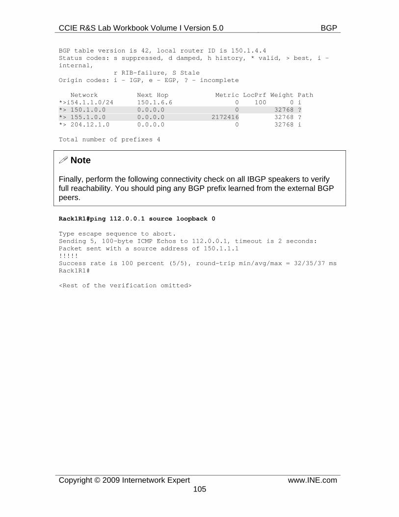
CCIE R&S Lab Workbook Volume I Version 5.0 BGP
Copyright © 2009 Internetwork Expert www.INE.com105
BGP table version is 42, local router ID is 150.1.4.4 Status codes: s suppressed, d damped, h history, * valid, > best, i - internal, r RIB-failure, S Stale Origin codes: i - IGP, e - EGP, ? - incomplete
Network Next Hop Metric LocPrf Weight Path *>i54.1.1.0/24 150.1.6.6 0 100 0 i *> 150.1.0.0 0.0.0.0 0 32768 ? *> 155.1.0.0 0.0.0.0 2172416 32768 ? *> 204.12.1.0 0.0.0.0 0 32768 i
Total number of prefixes 4
Note
Finally, perform the following connectivity check on all IBGP speakers to verify full reachability. You should ping any BGP prefix learned from the external BGP peers.
Rack1R1#ping 112.0.0.1 source loopback 0
Type escape sequence to abort. Sending 5, 100-byte ICMP Echos to 112.0.0.1, timeout is 2 seconds: Packet sent with a source address of 150.1.1.1 !!!!! Success rate is 100 percent (5/5), round-trip min/avg/max = 32/35/37 ms Rack1R1#
<Rest of the verification omitted>
CCIE R&S Lab Workbook Volume I Version 5.0 BGP
Copyright © 2009 Internetwork Expert www.INE.com106
7.18 BGP Bestpath Selection - Weight • Using the most influential attribute, configure SW1 so that traffic from AS
300 going to AS 54 prefixes exits towards R3, and that traffic from AS 300 going to AS 254 networks exits towards R6.
Configuration
Note
BGP Bestpath selection is the core of BGP routing process. This process replaces the shortest-path selection procedure found in traditional IGPs. The reason to use such complicated procedure instead of the shortest path is that BGP prefixes cannot have a classic (additive) metric associated with them. The purpose of the BGP bestpath procedure is to select optimal paths based on administrative preferences while maintaining the following properties:
1) Routing Loop detection. The best paths selected should form a loop-free topology. BGP implements this by filtering prefixes with the AS number matching the local AS in the AS_PATH attributes. 2) Deterministic path selection. All BGP routers under the same conditions (e.g. all IBGP speakers configured similarly) must select the same best paths. 2) Routing table stability. The best path selection procedure should not result in constant oscillating route insertion and removals. 3) Information flooding minimization. A BGP speaker only sends the best paths to its neighbors. This significantly reduces the amount of update flooding, saving bandwidth and CPU cycles.
Before we start with the best-path process description, recall that every BGP prefix has a set of attributes associated with it. The procedure uses those attributes when looking for optimal paths. Some of the attributes have more influence on the result than others, as we’ll see later. Before the procedure runs, the bestpath process excludes some prefixes based on the following criteria:
1) No valid next hop. This is the most common cause for the prefix being ignored by the selection process. BGP prefixes carry their next-hop is a separate attribute (NEXT_HOP attribute). If the next-hop address is NOT reachable via IGP, the prefix is marked as invalid and is not considered. Most often this happens with eBGP learned prefixes when you forget to enter the command nex-hop-self or advertise the link subnet into IGP/BGP. 2) BGP Synchronization enabled and the prefix is not in the IGP table. The bestpath process will ignore this prefix. This is a legacy restriction, but you may occasionally run into it, when using BGP synchronization. 3) Prefixes from the neighbor that has the local AS number in the AS_PATH attribute are dropped. This is the well-known BGP loop detection mechanism.
CCIE R&S Lab Workbook Volume I Version 5.0 BGP
Copyright © 2009 Internetwork Expert www.INE.com107
All eligible paths are then sorted and prefixes for the same destination (subnet/mask) are grouped together (the actual implementation may differ though, due to various optimizations). For every group, BGP must elect the best path. Here is a short outline of the steps performed by the selection process. Every step is tried if the previous one cannot reveal the best path:
1) Ignore invalid paths (no valid next hop, not synchronized, looped). 2) Prefer path with the highest locally assigned weight value. 3) Prefer path with the highest Local Preference attribute value. 4) Prefer locally originated prefixes (i.e. originated via the network, aggregate-address or redistribution commands). 5) Prefer path with the shortest AS_PATH attribute length 6) Prefer path with the lowest numerical value of the Origin code (IGP < EGP < Incomplete) 7) Prefer path with the lowest MED attribute value (provided that the first AS in the list is the same). 8) Prefer external BGP paths over Internal 9) Prefer path with the smallest IGP metric to reach the NEXT_HOP IP address 10) Prefer path originated from the router with the lowest BGP Router ID
Ahead of everything else, BGP prefers paths with the highest weight attribute. The weight attribute is Cisco-specific, and is not transported along with BGP prefixes. This attribute is configured locally in the router, using the command neighbor <IP_Address> weight 1-65535. As mentioned, higher weight values are preferred and the default weight is zero. Thus, among two equal prefixes with different weights the one with the highest weight is preferred. This attribute is commonly used in scenarios where the local router has multiple uplinks and you want to prefer one uplink over another. In addition to the neighbor command, weight attribute could be set using inbound route-map associated with the neighbor, for example:
route-map SET_WEIGHT math ip address ACCCESS_LIST set weight 100 ! router bgp 100 neighbor 204.12.1.254 route-map SET_WEIGHT in
This method could be used to change specific prefix preference without affecting any other subnets learned from the same peer. Remember that weight manipulations only affect the way that the traffic leaves the local router.
Notice that IOS routers assign the weight value of 32768 to all locally advertised prefixes – i.e. prefixes advertised using the network or aggregate-address commands or via route redistribution. This feature ensures that all locally
CCIE R&S Lab Workbook Volume I Version 5.0 BGP
Copyright © 2009 Internetwork Expert www.INE.com108
originated prefixes are always preferred again the same subnets learned from the peers.
The solution for this task uses AS-PATH access-lists to match all prefixes from AS 54 and 254. The regular expressions to match all networks originated from AS 54 and 254 respectively are “54$” and “254$”. SW1 peers with R6 and R3 and we manipulate weight values as follows:
1) For prefixes originated from AS 254 and received from R6 we set the weight value to 1000. This makes SW1 prefer paths to AS254 via R6, as opposed to R3. 2) For prefixes originate from AS 54 and received from R3 we set the weight value to 1000 as well. In result SW1 prefers paths to AS 54 via R3, while it should prefer paths via R6 by default.
Always remember to create a “permit” entry at the end of your route-maps, or you may end up filtering non-matching networks unintentionally.
SW1: no ip as-path access-list 1 no ip as-path access-list 2 ip as-path access-list 1 permit _54$ ip as-path access-list 2 permit _254$ ! route-map FROM_R6 permit 10 match as-path 2 set weight 1000 ! route-map FROM_R6 permit 100
! route-map FROM_R3 permit 10 match as-path 1 set weight 1000 ! route-map FROM_R3 permit 100 ! router bgp 300 neighbor 155.1.67.6 route-map FROM_R6 in neighbor 155.1.37.3 route-map FROM_R3 in
CCIE R&S Lab Workbook Volume I Version 5.0 BGP
Copyright © 2009 Internetwork Expert www.INE.com109
Verification
Note
Before you start any verification, use the command clear ip bgp * soft to force SW1 to refresh the information learned from its peers. By default, when you apply any new policy it does not take any effect unless the new updates are received/sent. Since BGP does not use periodic updates, you may need to force an update manually. The command performs a “soft-reset” - it does not tear down BGP sessions but simply sends out BGP updates and requests route-refresh from the peers. Compared to clear ip bgp * it causes much less load on router’s CPU and does not disrupt traffic routing.
Rack1SW1#clear ip bgp * soft
Note
Now let’s look through the BGP table in SW1. Notice the use of regex-based filter _54$ to select only the prefixes originated in AS 54. Look at the prefixes received from R3 – they are selected as “best” and marked with the “>” sign, and the weight assigned is 1000. The “losing” prefixes have the weight value of 0 (the default).
Rack1SW1#sh ip bgp regexp _54$ BGP table version is 18, local router ID is 150.1.7.7 Status codes: s suppressed, d damped, h history, * valid, > best, i - internal, r RIB-failure, S Stale Origin codes: i - IGP, e - EGP, ? - incomplete
Network Next Hop Metric LocPrf Weight Path * 28.119.16.0/24 155.1.67.6 0 100 54 i *> 155.1.37.3 1000 200 100 54 i * 28.119.17.0/24 155.1.67.6 0 100 54 i *> 155.1.37.3 1000 200 100 54 i * 114.0.0.0 155.1.67.6 0 100 54 i *> 155.1.37.3 1000 200 100 54 i * 115.0.0.0 155.1.67.6 0 100 54 i *> 155.1.37.3 1000 200 100 54 i * 116.0.0.0 155.1.67.6 0 100 54 i *> 155.1.37.3 1000 200 100 54 i * 117.0.0.0 155.1.67.6 0 100 54 i *> 155.1.37.3 1000 200 100 54 i * 118.0.0.0 155.1.67.6 0 100 54 i *> 155.1.37.3 1000 200 100 54 i * 119.0.0.0 155.1.67.6 0 100 54 i *> 155.1.37.3 1000 200 100 54 i
CCIE R&S Lab Workbook Volume I Version 5.0 BGP
Copyright © 2009 Internetwork Expert www.INE.com110
Note
Repeat the same check with the prefixes originated in AS 254. Notice that now R6 is selected as the upstream peer to route to these subnets.
Rack1SW1#sh ip bgp regexp 254$ BGP table version is 18, local router ID is 150.1.7.7 Status codes: s suppressed, d damped, h history, * valid, > best, i - internal, r RIB-failure, S Stale Origin codes: i - IGP, e - EGP, ? - incomplete
Network Next Hop Metric LocPrf Weight Path *> 205.90.31.0 155.1.67.6 1000 100 200 254 ? * 155.1.37.3 0 200 254 ? *> 220.20.3.0 155.1.67.6 1000 100 200 254 ? * 155.1.37.3 0 200 254 ? *> 222.22.2.0 155.1.67.6 1000 100 200 254 ? * 155.1.37.3 0 200 254 ?
CCIE R&S Lab Workbook Volume I Version 5.0 BGP
Copyright © 2009 Internetwork Expert www.INE.com111
7.19 BGP Bestpath Selection - Local Preference • Remove the BGP configuration for the previous task from SW1. • Use the local-preference in R6 so that traffic from AS 100 going to AS 254
transits through AS 300.
Configuration
Note
The next attribute that is compared among equal prefixes (assuming the weight for all prefixes is the same) is Local Preference (LP). This is a well-known discretionary attribute that defines how much is the prefix preferred within the scope of a single AS. Numerically higher value of the LP attribute makes BGP prefer the prefix over other with lower LP. Local Preference attribute is carried along with the prefix through the single AS (i.e. relayed across iBGP sessions) but does not leave the AS boundaries. This AS wide propagation ensures that all routers within the single AS perform deterministic path selection.
When you manipulate the local preference, you affect the way that traffic leaves the local AS. Local Preference is typically modified at the bordering BGP speakers, at the point of the particular external connection. To set the local preference for prefixes received from a peer you need to construct a route-map that matches the prefixes you want to manipulate and use the respective set command.
route-map SET_LP match ip address| match ip as-path ... set local-preference 1000
The maximum value for local preference is 2^32-1, since the attribute value is 32 bits in size. Keep in mind that by default all iBGP learned prefixes have the Local Preference value of 100 assigned to them. This is needed to give you some space for maneuver when lowering the local preference for some prefixes. If you want to change the default local preference value, use the command bgp default local-preference <value>. Naturally, this will only affect the default local preference in the router where it’s configured.
In this scenario, the default path from AS 100 to AS 254 is across AS 200, based on the AS_PATH length comparison (the step discussed in the following scenario). In order to affect the best-path selection, we configure R6 to assign local preference of 200 to AS 254 prefixes learned from SW1. This will make all routers in AS 100 prefer the exit point via SW1 to reach AS 254 prefixes. Similar to the previous scenarios, we use AS-PATH access-list to match the prefixes originated in AS 254.
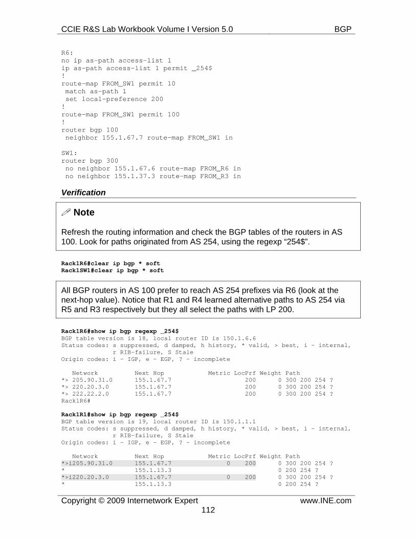
CCIE R&S Lab Workbook Volume I Version 5.0 BGP
Copyright © 2009 Internetwork Expert www.INE.com112
R6: no ip as-path access-list 1 ip as-path access-list 1 permit _254$ ! route-map FROM_SW1 permit 10 match as-path 1 set local-preference 200 ! route-map FROM_SW1 permit 100 ! router bgp 100 neighbor 155.1.67.7 route-map FROM_SW1 in
SW1: router bgp 300 no neighbor 155.1.67.6 route-map FROM_R6 in no neighbor 155.1.37.3 route-map FROM_R3 in
Verification
Note
Refresh the routing information and check the BGP tables of the routers in AS 100. Look for paths originated from AS 254, using the regexp “254$”.
Rack1R6#clear ip bgp * soft Rack1SW1#clear ip bgp * soft
All BGP routers in AS 100 prefer to reach AS 254 prefixes via R6 (look at the next-hop value). Notice that R1 and R4 learned alternative paths to AS 254 via R5 and R3 respectively but they all select the paths with LP 200.
Rack1R6#show ip bgp regexp _254$ BGP table version is 18, local router ID is 150.1.6.6 Status codes: s suppressed, d damped, h history, * valid, > best, i - internal, r RIB-failure, S Stale Origin codes: i - IGP, e - EGP, ? - incomplete
Network Next Hop Metric LocPrf Weight Path *> 205.90.31.0 155.1.67.7 200 0 300 200 254 ? *> 220.20.3.0 155.1.67.7 200 0 300 200 254 ? *> 222.22.2.0 155.1.67.7 200 0 300 200 254 ? Rack1R6#
Rack1R1#show ip bgp regexp _254$ BGP table version is 19, local router ID is 150.1.1.1 Status codes: s suppressed, d damped, h history, * valid, > best, i - internal, r RIB-failure, S Stale Origin codes: i - IGP, e - EGP, ? - incomplete
Network Next Hop Metric LocPrf Weight Path *>i205.90.31.0 155.1.67.7 0 200 0 300 200 254 ? * 155.1.13.3 0 200 254 ? *>i220.20.3.0 155.1.67.7 0 200 0 300 200 254 ? * 155.1.13.3 0 200 254 ?
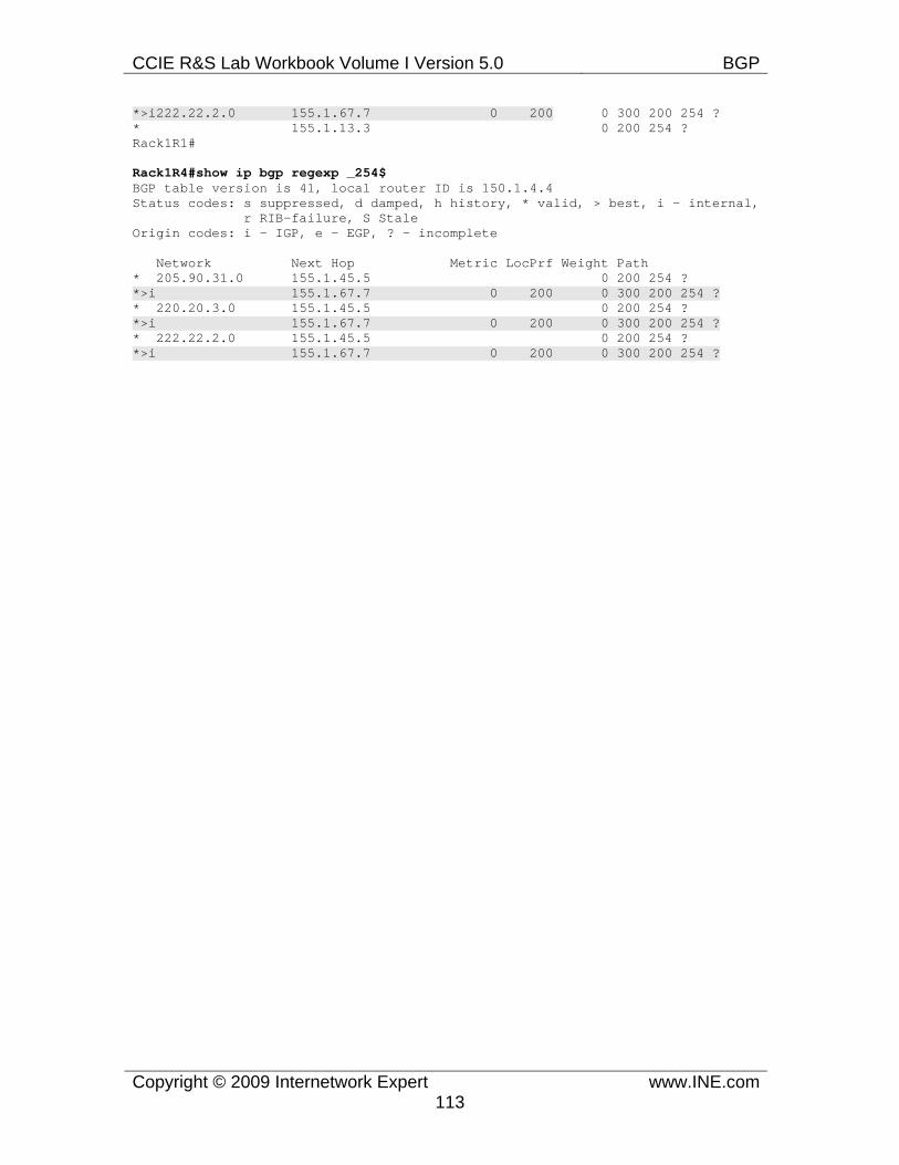
CCIE R&S Lab Workbook Volume I Version 5.0 BGP
Copyright © 2009 Internetwork Expert www.INE.com113
*>i222.22.2.0 155.1.67.7 0 200 0 300 200 254 ? * 155.1.13.3 0 200 254 ? Rack1R1#
Rack1R4#show ip bgp regexp _254$ BGP table version is 41, local router ID is 150.1.4.4 Status codes: s suppressed, d damped, h history, * valid, > best, i - internal, r RIB-failure, S Stale Origin codes: i - IGP, e - EGP, ? - incomplete
Network Next Hop Metric LocPrf Weight Path * 205.90.31.0 155.1.45.5 0 200 254 ? *>i 155.1.67.7 0 200 0 300 200 254 ? * 220.20.3.0 155.1.45.5 0 200 254 ? *>i 155.1.67.7 0 200 0 300 200 254 ? * 222.22.2.0 155.1.45.5 0 200 254 ? *>i 155.1.67.7 0 200 0 300 200 254 ?
CCIE R&S Lab Workbook Volume I Version 5.0 BGP
Copyright © 2009 Internetwork Expert www.INE.com114
7.20 BGP Bestpath Selection - AS-Path Prepending • Remove the BGP configuration for the previous task from R6. • Using AS-Path Prepending, configure AS 200 so that traffic from AS 100
going to AS 254 enters via the link to AS 300.
Configuration
Note
When two prefixes for the same destination have equal weights and local preference values, BGP process will prefer the prefix originated locally – i.e. the prefix advertised via the network command, aggregate-address or redistribution. In IOS routers this step is usually superfluous, as the locally originated prefixes have weight value of 32768, overriding all other steps of BGP bestpath selection process.
The next step in the process is selecting the prefix with the shortest AS_PATH. The length of this attribute is probably the best approximation of the classic IGP metric when mapping this concept to BGP. This could be directly compared to the hop count concept used in RIP. Here is the procedure for computing the AS_PATH length:
1) For every AS_SEQUENCE element, every AS in the list counts as one and the resulting sum is the number of entries in the path. 2) If the prefix was a result of summarization, you may encounter the AS_SET elements in the AS_PATH. The length of AS_SET is assumed to be “1”. This is because summarization conceals topology information, and the summarized prefixes may have had different AS_PATH lengths. 3) If the prefix has been originated within the BGP Confederation, then its AS_PATH attribute may contain any of BGP_CONFED_SEQUENCE or BGP_CONFED_SET sub-attributes. The second sub-attribute appears when you summarize prefixes inside confederation. Each of these elements does not count when computing the AS PATH length.
In order to use this step to influence best path selection, you should use the AS_PATH prepending procedure. This procedure applies only to eBGP sessions, i.e. when advertising prefixes to another AS and the local AS number is prepended in front of the AS_PATH attribute the number of times specified. The syntax to perform AS_PATH prending is as follows, assuming that the local AS number is 100:
route-map PREPEND match ... set as-path prepend 100 100 100
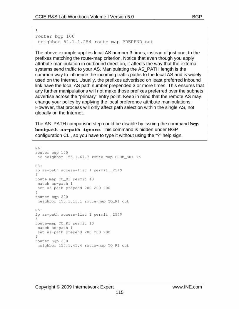
CCIE R&S Lab Workbook Volume I Version 5.0 BGP
Copyright © 2009 Internetwork Expert www.INE.com115
! router bgp 100 neighbor 54.1.1.254 route-map PREPEND out
The above example applies local AS number 3 times, instead of just one, to the prefixes matching the route-map criterion. Notice that even though you apply attribute manipulation in outbound direction, it affects the way that the external systems send traffic to your AS. Manipulating the AS_PATH length is the common way to influence the incoming traffic paths to the local AS and is widely used on the Internet. Usually, the prefixes advertised on least preferred inbound link have the local AS path number prepended 3 or more times. This ensures that any further manipulations will not make those prefixes preferred over the subnets advertise across the “primary” entry point. Keep in mind that the remote AS may change your policy by applying the local preference attribute manipulations. However, that process will only affect path selection within the single AS, not globally on the Internet.
The AS_PATH comparison step could be disable by issuing the command bgp bestpath as-path ignore. This command is hidden under BGP configuration CLI, so you have to type it without using the “?” help sign.
R6: router bgp 100 no neighbor 155.1.67.7 route-map FROM_SW1 in
R3: ip as-path access-list 1 permit _254$ ! route-map TO_R1 permit 10 match as-path 1 set as-path prepend 200 200 200 ! router bgp 200 neighbor 155.1.13.1 route-map TO_R1 out
R5: ip as-path access-list 1 permit _254$ ! route-map TO_R1 permit 10 match as-path 1 set as-path prepend 200 200 200 ! router bgp 200 neighbor 155.1.45.4 route-map TO_R1 out
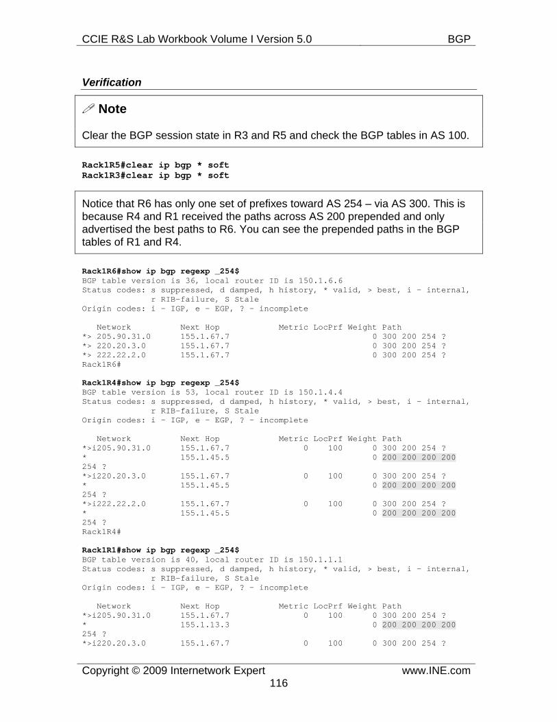
CCIE R&S Lab Workbook Volume I Version 5.0 BGP
Copyright © 2009 Internetwork Expert www.INE.com116
Verification
Note
Clear the BGP session state in R3 and R5 and check the BGP tables in AS 100.
Rack1R5#clear ip bgp * soft Rack1R3#clear ip bgp * soft
Notice that R6 has only one set of prefixes toward AS 254 – via AS 300. This is because R4 and R1 received the paths across AS 200 prepended and only advertised the best paths to R6. You can see the prepended paths in the BGP tables of R1 and R4.
Rack1R6#show ip bgp regexp _254$ BGP table version is 36, local router ID is 150.1.6.6 Status codes: s suppressed, d damped, h history, * valid, > best, i - internal, r RIB-failure, S Stale Origin codes: i - IGP, e - EGP, ? - incomplete
Network Next Hop Metric LocPrf Weight Path *> 205.90.31.0 155.1.67.7 0 300 200 254 ? *> 220.20.3.0 155.1.67.7 0 300 200 254 ? *> 222.22.2.0 155.1.67.7 0 300 200 254 ? Rack1R6#
Rack1R4#show ip bgp regexp _254$ BGP table version is 53, local router ID is 150.1.4.4 Status codes: s suppressed, d damped, h history, * valid, > best, i - internal, r RIB-failure, S Stale Origin codes: i - IGP, e - EGP, ? - incomplete
Network Next Hop Metric LocPrf Weight Path *>i205.90.31.0 155.1.67.7 0 100 0 300 200 254 ? * 155.1.45.5 0 200 200 200 200 254 ? *>i220.20.3.0 155.1.67.7 0 100 0 300 200 254 ? * 155.1.45.5 0 200 200 200 200 254 ? *>i222.22.2.0 155.1.67.7 0 100 0 300 200 254 ? * 155.1.45.5 0 200 200 200 200 254 ? Rack1R4#
Rack1R1#show ip bgp regexp _254$ BGP table version is 40, local router ID is 150.1.1.1 Status codes: s suppressed, d damped, h history, * valid, > best, i - internal, r RIB-failure, S Stale Origin codes: i - IGP, e - EGP, ? - incomplete
Network Next Hop Metric LocPrf Weight Path *>i205.90.31.0 155.1.67.7 0 100 0 300 200 254 ? * 155.1.13.3 0 200 200 200 200 254 ? *>i220.20.3.0 155.1.67.7 0 100 0 300 200 254 ?
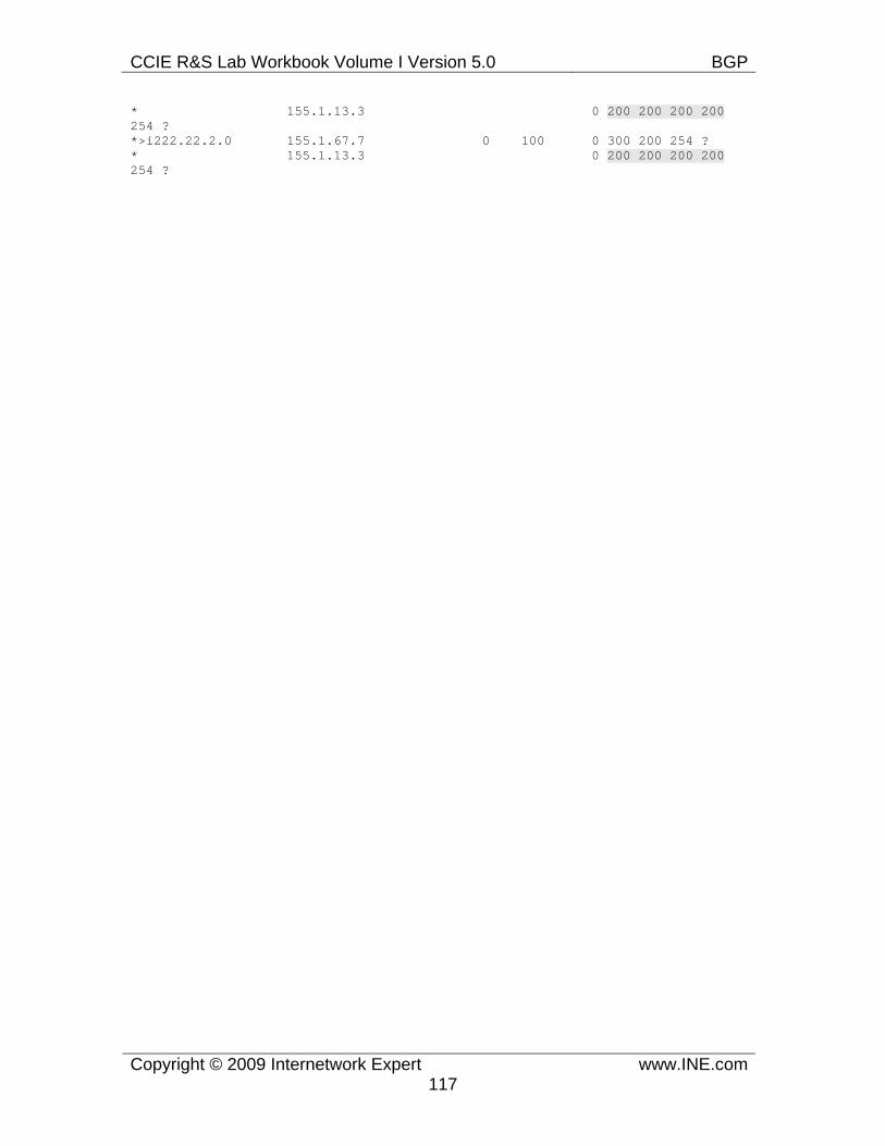
CCIE R&S Lab Workbook Volume I Version 5.0 BGP
Copyright © 2009 Internetwork Expert www.INE.com117
* 155.1.13.3 0 200 200 200 200 254 ? *>i222.22.2.0 155.1.67.7 0 100 0 300 200 254 ? * 155.1.13.3 0 200 200 200 200 254 ?
CCIE R&S Lab Workbook Volume I Version 5.0 BGP
Copyright © 2009 Internetwork Expert www.INE.com118
7.21 BGP Bestpath Selection - Origin • Remove the BGP configuration made for the previous task. • Using Origin attribute configure AS 200 so that traffic from AS 100 going
to AS 254 enters via the link between R4 and R5.
Configuration
Note
If BGP prefixes have equal weight, local preference and AS_PATH length, then the bestpath selection process compares routes Origin. This attribute is well-known and mandatory and is set by the prefix originator. The allowed values are the following: 1) “IGP”, meaning the route was originated using the network or aggregate-address command. It appears as “i” in BGP table output. 2) “EGP”, meaning the prefix was received from an EGP peer (legacy). You won’t probably see this Origin value in any modern router. 3) “Incomplete” meaning the source could not be determined. This Origin is assigned to the prefixes redistributed into BGP.
This attribute is rarely used to influence the path selection, due to its inflexibility. Nevertheless BGP always account for this step. Origin “IGP” is preferred over “EGP” and the latter is preferred over “Incomplete”. This represents the level of “trust” that BGP assigns to various information sources.
In this task we configure the borders routers in AS 200 (R3 and R5) to impose different Origin attribute on the links between R1, R3 and R4, R5. The prefixes advertised to R1 have the Origin value or “Incomplete” while the prefixes advertised to R4 have the Origin value of “IGP”.
R3: router bgp 200 no neighbor 155.1.13.1 route-map TO_R1 out ! no route-map TO_R1
R5:
router bgp 200 no neighbor 155.1.45.4 route-map TO_R4 out ! no route-map TO_R4
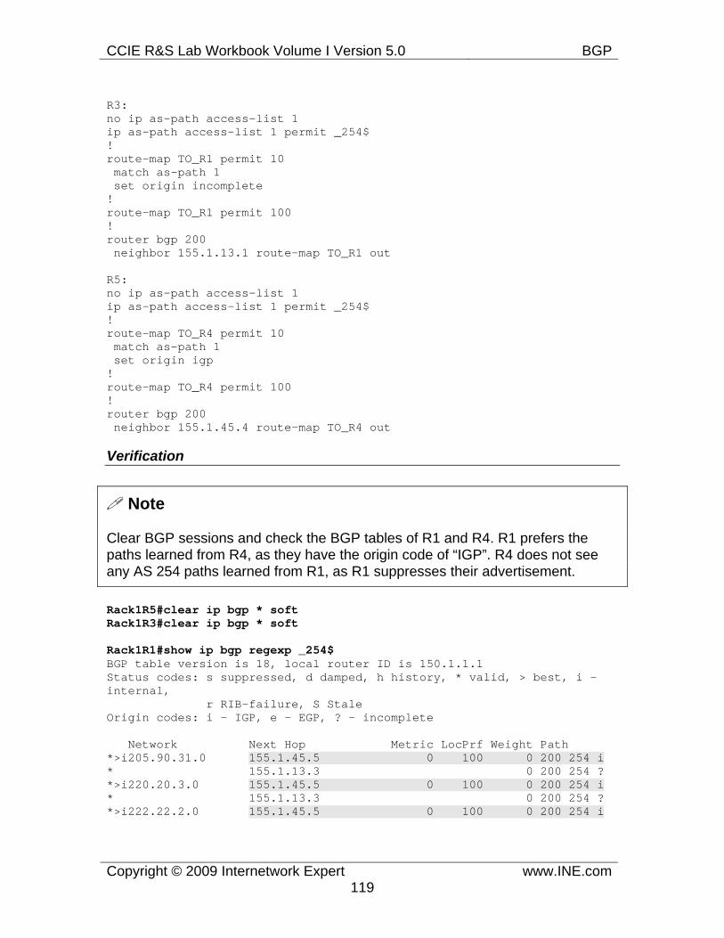
CCIE R&S Lab Workbook Volume I Version 5.0 BGP
Copyright © 2009 Internetwork Expert www.INE.com119
R3: no ip as-path access-list 1 ip as-path access-list 1 permit _254$ ! route-map TO_R1 permit 10 match as-path 1 set origin incomplete ! route-map TO_R1 permit 100 ! router bgp 200 neighbor 155.1.13.1 route-map TO_R1 out
R5: no ip as-path access-list 1 ip as-path access-list 1 permit _254$ ! route-map TO_R4 permit 10 match as-path 1 set origin igp ! route-map TO_R4 permit 100 ! router bgp 200 neighbor 155.1.45.4 route-map TO_R4 out
Verification
Note
Clear BGP sessions and check the BGP tables of R1 and R4. R1 prefers the paths learned from R4, as they have the origin code of “IGP”. R4 does not see any AS 254 paths learned from R1, as R1 suppresses their advertisement.
Rack1R5#clear ip bgp * soft Rack1R3#clear ip bgp * soft
Rack1R1#show ip bgp regexp _254$ BGP table version is 18, local router ID is 150.1.1.1 Status codes: s suppressed, d damped, h history, * valid, > best, i - internal, r RIB-failure, S Stale Origin codes: i - IGP, e - EGP, ? - incomplete
Network Next Hop Metric LocPrf Weight Path *>i205.90.31.0 155.1.45.5 0 100 0 200 254 i * 155.1.13.3 0 200 254 ? *>i220.20.3.0 155.1.45.5 0 100 0 200 254 i * 155.1.13.3 0 200 254 ? *>i222.22.2.0 155.1.45.5 0 100 0 200 254 i
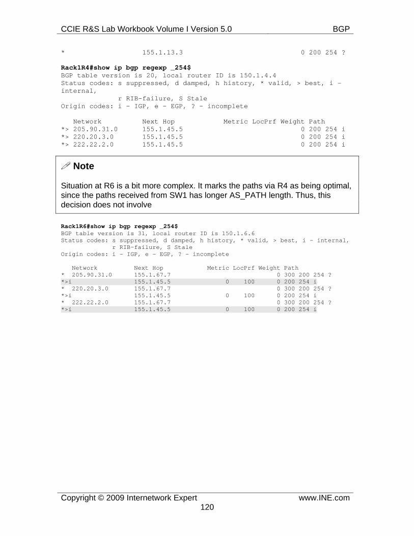
CCIE R&S Lab Workbook Volume I Version 5.0 BGP
Copyright © 2009 Internetwork Expert www.INE.com120
* 155.1.13.3 0 200 254 ?
Rack1R4#show ip bgp regexp _254$ BGP table version is 20, local router ID is 150.1.4.4 Status codes: s suppressed, d damped, h history, * valid, > best, i - internal, r RIB-failure, S Stale Origin codes: i - IGP, e - EGP, ? - incomplete
Network Next Hop Metric LocPrf Weight Path *> 205.90.31.0 155.1.45.5 0 200 254 i *> 220.20.3.0 155.1.45.5 0 200 254 i *> 222.22.2.0 155.1.45.5 0 200 254 i
Note
Situation at R6 is a bit more complex. It marks the paths via R4 as being optimal, since the paths received from SW1 has longer AS_PATH length. Thus, this decision does not involve
Rack1R6#show ip bgp regexp _254$ BGP table version is 31, local router ID is 150.1.6.6 Status codes: s suppressed, d damped, h history, * valid, > best, i - internal, r RIB-failure, S Stale Origin codes: i - IGP, e - EGP, ? - incomplete
Network Next Hop Metric LocPrf Weight Path * 205.90.31.0 155.1.67.7 0 300 200 254 ? *>i 155.1.45.5 0 100 0 200 254 i * 220.20.3.0 155.1.67.7 0 300 200 254 ? *>i 155.1.45.5 0 100 0 200 254 i * 222.22.2.0 155.1.67.7 0 300 200 254 ? *>i 155.1.45.5 0 100 0 200 254 i
CCIE R&S Lab Workbook Volume I Version 5.0 BGP
Copyright © 2009 Internetwork Expert www.INE.com121
7.22 BGP Bestpath Selection - MED • Remove the BGP configuration made for the previous task. • Using MED configure AS 100 so that traffic from AS 200 going to AS 54
enters via the link between R4 and R5.
Configuration
Note
If all prefixes have the same Origin, BGP will compare the next less influential attribute – MED or Multi Exit Discriminator. This is attribute is optional non-transitive and its value is an unsigned 32 integer. It is often called “metric” and used on eBGP peering links to select the entry point to the neighboring AS. The AS that originates the prefixes may attach different metric values to them on different exit points from the AS. This hints the neighboring AS to select the best path based on the smallest metric value, since all other attributes usually match (i.e. weight, LP, AS_PATH length).
The MED attribute is non-transitive, and thus the receiving AS will not propagate it across the borders. However, the receiving AS may reset the metric value, if it wants. Cisco BGP implementation automatically assign the value of the MED attribute based on the IGP metric value for the locally originate prefixes. Here is the reasoning behind that.
Most often, BGP prefixes are advertised by the border eBGP speakers. If there are redundant connections between two ASes, multiple BGP speakers may originate the same prefix, attaching the MED attribute copied from the IGP metric of the advertised prefix. The neighboring AS may then apply the bestpath selection for the peer’s prefixes based on the smallest metric value. This makes sense, if the following holds true:
1) The peer (originator) AS uses single IGP across its network, i.e. metric values are numerically comparable. 2) MED values are only compared for the prefixes coming from the same AS. 3) Prefixes were originated from the peer’s AS.
Based on these assumptions, MED attribute simply hints the neighboring AS to select the prefixes with the shortest IGP metric value in the peer’s AS. This routing behavior is called “cold potato routing” in contrary to the “hot potato” routing model. The “hot potato” model is effectively in use when MED values are not considered during the bestpath selection. When MED values are filtered or are the same among all prefixes, the router will select the prefix with the lowest IGP cost for its next-hop (if the prefixes are of the same type – e.g. both learned via iBGP, then comparing IGP costs is the next step in BGP bespath selection
CCIE R&S Lab Workbook Volume I Version 5.0 BGP
Copyright © 2009 Internetwork Expert www.INE.com122
process). This means selecting the path through the closest exit point, based on the IGP metrics of the local AS. This is allegorically analogous to a group of persons trying to get rid of a “hot potato” as fast as possible. The “cold potato” routing model considers the metric hint information from the adjacent AS to make the final routing decision.
Often you may see MED attribute used to influence the exit point selection for prefixes not originated in the local AS. This is perfectly legal, but you need to assign some artificial metric values to these prefixes, as they don’t belong to the local AS IGP. Keep in mind that this sort of path attributes manipulation only affects the paths chosen by the directly connected neighboring AS. Lastly, MED attribute is optional and thus may not be present in all prefixes. By default, BGP process will assume the MED value of zero for such prefixes, which will make them more preferred during the selection based on metric. If you want to change this behavior, you need to enter the command bgp bestpath med missing-as-worst. This will instruct the local router to impose the maximum MED value on the prefixes that does not carry the MED attribute, making these prefixes least preferable. The use of this logic was specified in earlier drafts of the BGP specification, while the most recent instructs to assign the MED value of zero to the prefixes lacking the metric attribute.
In our scenario, we configure AS 100 border routers (R1 and R4) peering with AS 200 to assign metric values for prefixes learned from AS 54. The metrics are assigned so that exit point through R1 is less preferred (higher metric). Notice that we configure both R1 and R4, whereas it is possible to configure just R1, since routes advertised by R4 will have the default MED value of 0.
R3: router bgp 200 no neighbor 155.1.13.1 route-map TO_R1 out ! no route-map TO_R1
R5: router bgp 200 no neighbor 155.1.45.4 route-map TO_R4 out ! no route-map TO_R4
R1: no ip as-path access-list 1 ip as-path access-list 1 permit _54$ ! no route-map TO_R3 route-map TO_R3 permit 10 match as-path 1 set metric 1000 ! route-map TO_R3 permit 100 !
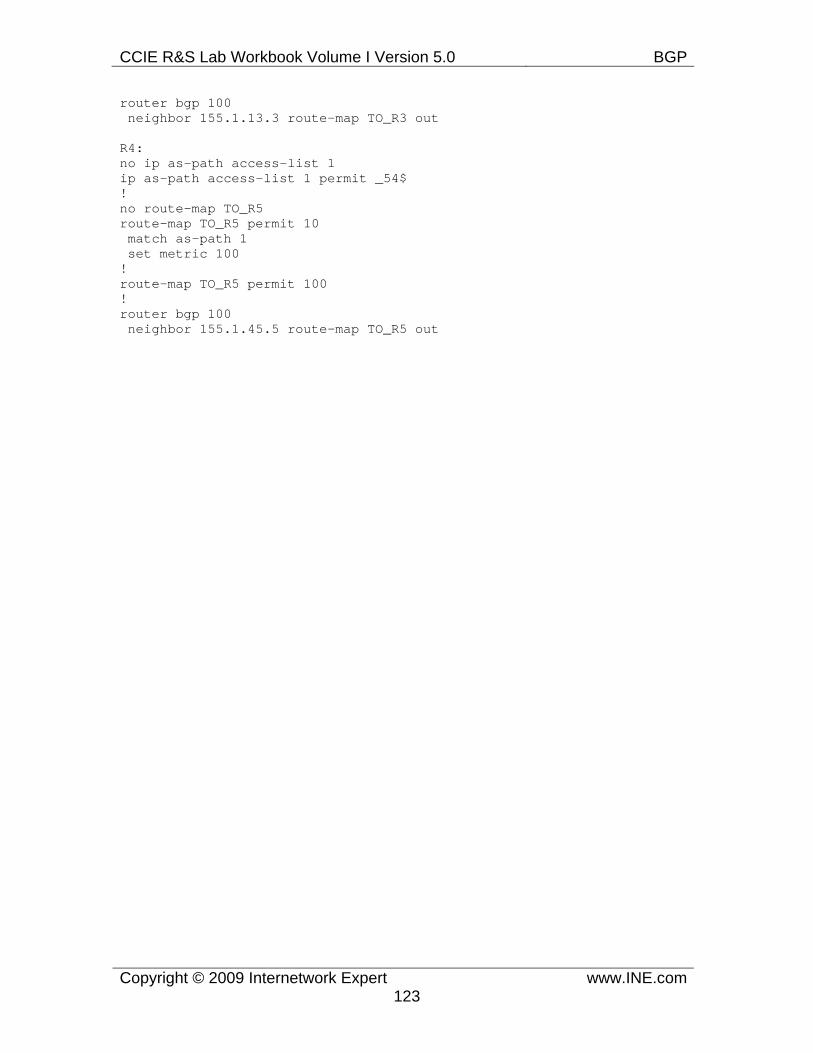
CCIE R&S Lab Workbook Volume I Version 5.0 BGP
Copyright © 2009 Internetwork Expert www.INE.com123
router bgp 100 neighbor 155.1.13.3 route-map TO_R3 out
R4: no ip as-path access-list 1 ip as-path access-list 1 permit _54$ ! no route-map TO_R5 route-map TO_R5 permit 10 match as-path 1 set metric 100 ! route-map TO_R5 permit 100 ! router bgp 100 neighbor 155.1.45.5 route-map TO_R5 out
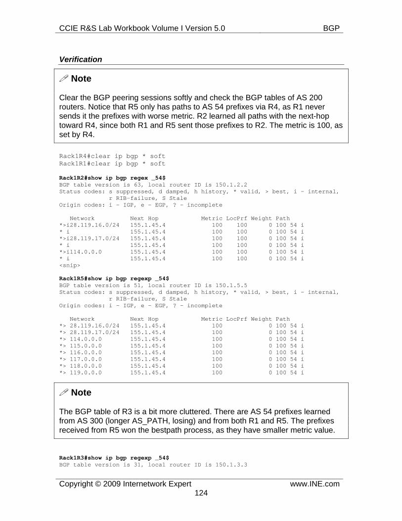
CCIE R&S Lab Workbook Volume I Version 5.0 BGP
Copyright © 2009 Internetwork Expert www.INE.com124
Verification
Note
Clear the BGP peering sessions softly and check the BGP tables of AS 200 routers. Notice that R5 only has paths to AS 54 prefixes via R4, as R1 never sends it the prefixes with worse metric. R2 learned all paths with the next-hop toward R4, since both R1 and R5 sent those prefixes to R2. The metric is 100, as set by R4.
Rack1R4#clear ip bgp * soft Rack1R1#clear ip bgp * soft
Rack1R2#show ip bgp regex _54$ BGP table version is 63, local router ID is 150.1.2.2 Status codes: s suppressed, d damped, h history, * valid, > best, i - internal, r RIB-failure, S Stale Origin codes: i - IGP, e - EGP, ? - incomplete
Network Next Hop Metric LocPrf Weight Path *>i28.119.16.0/24 155.1.45.4 100 100 0 100 54 i * i 155.1.45.4 100 100 0 100 54 i *>i28.119.17.0/24 155.1.45.4 100 100 0 100 54 i * i 155.1.45.4 100 100 0 100 54 i *>i114.0.0.0 155.1.45.4 100 100 0 100 54 i * i 155.1.45.4 100 100 0 100 54 i <snip>
Rack1R5#show ip bgp regexp _54$ BGP table version is 51, local router ID is 150.1.5.5 Status codes: s suppressed, d damped, h history, * valid, > best, i - internal, r RIB-failure, S Stale Origin codes: i - IGP, e - EGP, ? - incomplete
Network Next Hop Metric LocPrf Weight Path *> 28.119.16.0/24 155.1.45.4 100 0 100 54 i *> 28.119.17.0/24 155.1.45.4 100 0 100 54 i *> 114.0.0.0 155.1.45.4 100 0 100 54 i *> 115.0.0.0 155.1.45.4 100 0 100 54 i *> 116.0.0.0 155.1.45.4 100 0 100 54 i *> 117.0.0.0 155.1.45.4 100 0 100 54 i *> 118.0.0.0 155.1.45.4 100 0 100 54 i *> 119.0.0.0 155.1.45.4 100 0 100 54 i
Note
The BGP table of R3 is a bit more cluttered. There are AS 54 prefixes learned from AS 300 (longer AS_PATH, losing) and from both R1 and R5. The prefixes received from R5 won the bestpath process, as they have smaller metric value.
Rack1R3#show ip bgp regexp _54$ BGP table version is 31, local router ID is 150.1.3.3
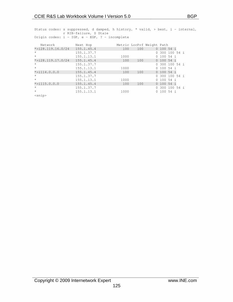
CCIE R&S Lab Workbook Volume I Version 5.0 BGP
Copyright © 2009 Internetwork Expert www.INE.com125
Status codes: s suppressed, d damped, h history, * valid, > best, i - internal, r RIB-failure, S Stale Origin codes: i - IGP, e - EGP, ? - incomplete
Network Next Hop Metric LocPrf Weight Path *>i28.119.16.0/24 155.1.45.4 100 100 0 100 54 i * 155.1.37.7 0 300 100 54 i * 155.1.13.1 1000 0 100 54 i *>i28.119.17.0/24 155.1.45.4 100 100 0 100 54 i * 155.1.37.7 0 300 100 54 i * 155.1.13.1 1000 0 100 54 i *>i114.0.0.0 155.1.45.4 100 100 0 100 54 i * 155.1.37.7 0 300 100 54 i * 155.1.13.1 1000 0 100 54 i *>i115.0.0.0 155.1.45.4 100 100 0 100 54 i * 155.1.37.7 0 300 100 54 i * 155.1.13.1 1000 0 100 54 i <snip>
CCIE R&S Lab Workbook Volume I Version 5.0 BGP
Copyright © 2009 Internetwork Expert www.INE.com126
7.24 BGP Bestpath Selection - Always Compare MED • Remove the BGP configuration made for the previous task. • Create a new Loopback1 interface on both R6 and SW3 with the IP
address 1.2.3.4/32 and advertise it into BGP on both R6 and SW3. • Using just the MED attribute configure the network so that traffic from AS
200 going to this prefix is always received by SW3.
Configuration
Note
As discussed previously, comparing automatically generated MED attributes makes sense only if all prefixes are originated from directly connected AS. However, setting the artificial MED values is often used by adjacent AS to hint the exit point to its peers. Now imagine a situation when the local AS (A) peers with two other ASes (B and C), and the peers have some sort of “backdoor” link between then, e.g. running an IGP on this link. Upon an agreement, the peers may decide to “share” their entry points, so that “A” may send traffic to a subset of “B”’s prefixes across “C” and vice versa. This could be done using the proper manipulation of MED attribute as the prefixes appear to be internal to both ASes, but classic BGP procedure does not compare MEDs for prefixes that were received from different ASes.
This limitation could be disabled by entering the command bgp always-compare-med under BGP configuration mode. This will instruct BGP code to ignore the first AS# in the AS_PATH attributes when comparing MED values. Of course, this is only possible if the AS_PATH lengths are the same. Using MED for exit point selection to multiple adjacent ASes is getting common, though its against the idea of using MED as a reflection of the internal IGP cost for a prefix. Essentially, this procedure assumes that the adjacent systems have an agreement about MED values assignment, and the local AS accepts their policy.
Through the history of BGP implementation, it has become apparent that using MED in bestpath selection may sometimes result in unstable routing tables or routing loops. There are many different scenarios, where such issues may arise. Particularly, Cisco’s BGP implementation suffered from non-deterministic MED-based path selection. What that means is that the result of best-path selection may depend on the order that the local speaker receives BGP prefixes. Specifically, IOS code was ordering BGP prefixes based on their age and compare then in pairs, starting with the newer prefixes. This temporal dependency was intended to make routing tables more stable, by giving more preference for older information. However, when the MED issues become apparent, Cisco implemented a workaround, that removed temporal dependency in MED-based computations. The resulting procedure became deterministic, and
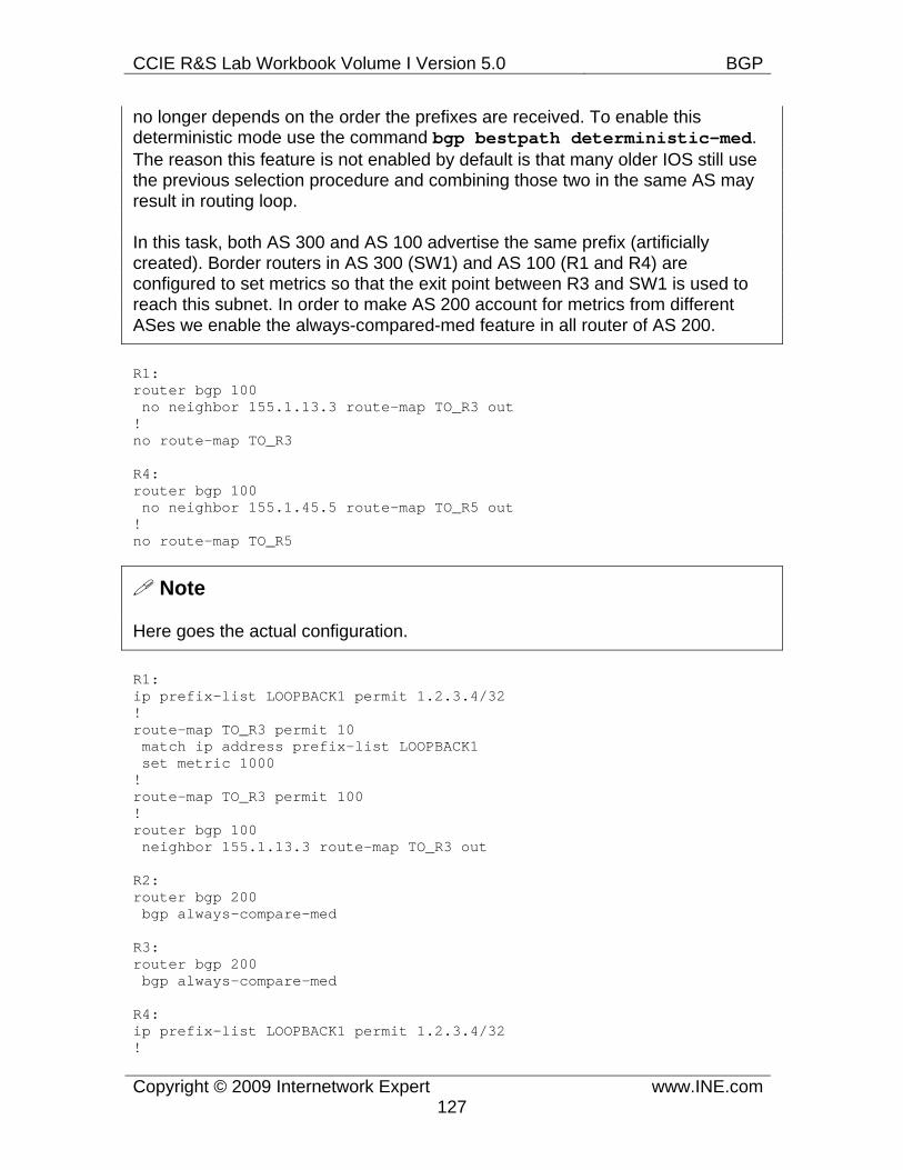
CCIE R&S Lab Workbook Volume I Version 5.0 BGP
Copyright © 2009 Internetwork Expert www.INE.com127
no longer depends on the order the prefixes are received. To enable this deterministic mode use the command bgp bestpath deterministic-med. The reason this feature is not enabled by default is that many older IOS still use the previous selection procedure and combining those two in the same AS may result in routing loop.
In this task, both AS 300 and AS 100 advertise the same prefix (artificially created). Border routers in AS 300 (SW1) and AS 100 (R1 and R4) are configured to set metrics so that the exit point between R3 and SW1 is used to reach this subnet. In order to make AS 200 account for metrics from different ASes we enable the always-compared-med feature in all router of AS 200.
R1: router bgp 100 no neighbor 155.1.13.3 route-map TO_R3 out ! no route-map TO_R3
R4: router bgp 100 no neighbor 155.1.45.5 route-map TO_R5 out ! no route-map TO_R5
Note
Here goes the actual configuration.
R1: ip prefix-list LOOPBACK1 permit 1.2.3.4/32 ! route-map TO_R3 permit 10 match ip address prefix-list LOOPBACK1 set metric 1000 ! route-map TO_R3 permit 100 ! router bgp 100 neighbor 155.1.13.3 route-map TO_R3 out
R2: router bgp 200 bgp always-compare-med
R3: router bgp 200 bgp always-compare-med
R4: ip prefix-list LOOPBACK1 permit 1.2.3.4/32 !
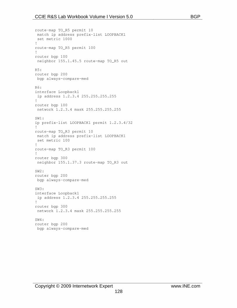
CCIE R&S Lab Workbook Volume I Version 5.0 BGP
Copyright © 2009 Internetwork Expert www.INE.com128
route-map TO_R5 permit 10 match ip address prefix-list LOOPBACK1 set metric 1000 ! route-map TO_R5 permit 100 ! router bgp 100 neighbor 155.1.45.5 route-map TO_R5 out
R5: router bgp 200 bgp always-compare-med
R6: interface Loopback1 ip address 1.2.3.4 255.255.255.255 ! router bgp 100 network 1.2.3.4 mask 255.255.255.255
SW1: ip prefix-list LOOPBACK1 permit 1.2.3.4/32 ! route-map TO_R3 permit 10 match ip address prefix-list LOOPBACK1 set metric 100 ! route-map TO_R3 permit 100 ! router bgp 300 neighbor 155.1.37.3 route-map TO_R3 out
SW2: router bgp 200 bgp always-compare-med
SW3: interface Loopback1 ip address 1.2.3.4 255.255.255.255 ! router bgp 300 network 1.2.3.4 mask 255.255.255.255
SW4: router bgp 200 bgp always-compare-med
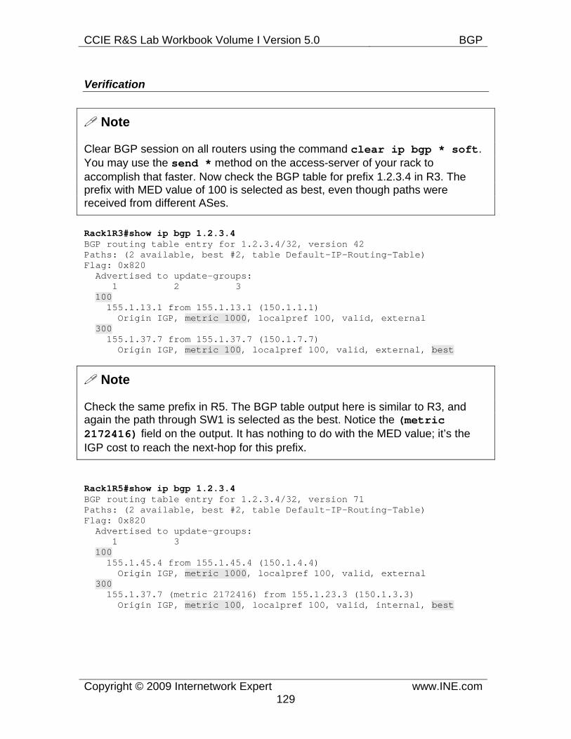
CCIE R&S Lab Workbook Volume I Version 5.0 BGP
Copyright © 2009 Internetwork Expert www.INE.com129
Verification
Note
Clear BGP session on all routers using the command clear ip bgp * soft. You may use the send * method on the access-server of your rack to accomplish that faster. Now check the BGP table for prefix 1.2.3.4 in R3. The prefix with MED value of 100 is selected as best, even though paths were received from different ASes.
Rack1R3#show ip bgp 1.2.3.4 BGP routing table entry for 1.2.3.4/32, version 42 Paths: (2 available, best #2, table Default-IP-Routing-Table) Flag: 0x820 Advertised to update-groups: 1 2 3 100 155.1.13.1 from 155.1.13.1 (150.1.1.1) Origin IGP, metric 1000, localpref 100, valid, external 300 155.1.37.7 from 155.1.37.7 (150.1.7.7) Origin IGP, metric 100, localpref 100, valid, external, best
Note
Check the same prefix in R5. The BGP table output here is similar to R3, and again the path through SW1 is selected as the best. Notice the (metric 2172416) field on the output. It has nothing to do with the MED value; it’s the IGP cost to reach the next-hop for this prefix.
Rack1R5#show ip bgp 1.2.3.4 BGP routing table entry for 1.2.3.4/32, version 71 Paths: (2 available, best #2, table Default-IP-Routing-Table) Flag: 0x820 Advertised to update-groups: 1 3 100 155.1.45.4 from 155.1.45.4 (150.1.4.4) Origin IGP, metric 1000, localpref 100, valid, external 300 155.1.37.7 (metric 2172416) from 155.1.23.3 (150.1.3.3) Origin IGP, metric 100, localpref 100, valid, internal, best
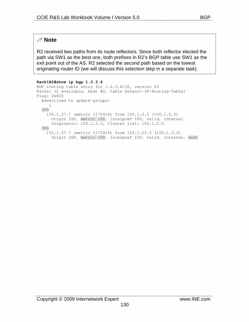
CCIE R&S Lab Workbook Volume I Version 5.0 BGP
Copyright © 2009 Internetwork Expert www.INE.com130
Note
R2 received two paths from its route reflectors. Since both reflector elected the path via SW1 as the best one, both prefixes in R2’s BGP table use SW1 as the exit point out of the AS. R2 selected the second path based on the lowest originating router ID (we will discuss this selection step in a separate task).
Rack1R2#show ip bgp 1.2.3.4 BGP routing table entry for 1.2.3.4/32, version 83 Paths: (2 available, best #2, table Default-IP-Routing-Table) Flag: 0x820 Advertised to update-groups: 1 300 155.1.37.7 (metric 2172416) from 155.1.0.5 (150.1.5.5) Origin IGP, metric 100, localpref 100, valid, internal Originator: 150.1.3.3, Cluster list: 150.1.5.5 300 155.1.37.7 (metric 2172416) from 155.1.23.3 (150.1.3.3) Origin IGP, metric 100, localpref 100, valid, internal, best
CCIE R&S Lab Workbook Volume I Version 5.0 BGP
Copyright © 2009 Internetwork Expert www.INE.com131
7.25 BGP Bestpath Selection - AS-Path Ignore • Remove the BGP configuration made for the previous task. • Ensure that traffic from AS 200 to AS 54 prefixes takes path across AS
300. • Do not use AS-PATH prepending to accomplish this.
Configuration
Note
Ignoring AS_PATH length comparison is optional and could be enabled using a special hidden command. Using this feature in production is highly not recommended as it may severely affect routing table’s stability. However, if you need it just for some non-standard tweak of you BGP path selection, use the command bgp bestpath as-path ignore to activate this feature. BGP will automatically skip AS_PATH length comparison and proceed to comparing the Origin codes, MED attribute and the IGP costs for NEXT_HOPs.
One particular case where you may actually need this feature is BGP confederations. As you remember, BGP_CONFED_SEQUENCE and BGP_CONFED_SET do not count when computing the AS_PATH length. Therefore, in BGP confederations you may see suboptimal paths being elected simply based on the AS_PATH attribute carried from the external ASes (internal path lengths are ignored). By disabling the AS_PATH comparison you may force the local speakers to use the “hot patato” routing model, taking in account the IGP cost to reach the prefix NEXT_HOP. That is, only provided if all prefixes have the same Origin and MED attribute values, which could be enforced by border BGP speakers.
In this scenario we modify the Origin attribute for paths injected into AS 200 through the peering connection SW1-R3. All routes in AS 200 has AS_PATH length comparison disabled, and thus prefer the paths to AS 54 learned from SW1 even though those have longer AS_PATHs.
R1: router bgp 100 no neighbor 155.1.13.3 route-map TO_R3 out ! no route-map TO_R3
R4: router bgp 100 neighbor 155.1.45.5 route-map TO_R5 out ! no route-map TO_R5 permit 100
CCIE R&S Lab Workbook Volume I Version 5.0 BGP
Copyright © 2009 Internetwork Expert www.INE.com132
R6: no interface Loopback1 ! router bgp 100 no network 1.2.3.4 mask 255.255.255.255
SW1: router bgp 300 no neighbor 155.1.37.3 route-map TO_R3 out ! no route-map TO_R3
SW3: no interface Loopback1 ! router bgp 300 no network 1.2.3.4 mask 255.255.255.255
Note
Now the actual configuration for this task
R1: no ip as-path access-list 1 ip as-path access-list 1 permit _54$ ! route-map TO_R3 permit 10 match as-path 1 set origin incomplete ! route-map TO_R3 permit 100 ! router bgp 100 neighbor 155.1.13.3 route-map TO_R3 out
R2: router bgp 200 bgp bestpath as-path ignore
R3: router bgp 200 bgp bestpath as-path ignore
R4: no ip as-path access-list 1 ip as-path access-list 1 permit _54$ ! route-map TO_R5 permit 10 match as-path 1 set origin incomplete ! route-map TO_R5 permit 100
CCIE R&S Lab Workbook Volume I Version 5.0 BGP
Copyright © 2009 Internetwork Expert www.INE.com133
! router bgp 100 neighbor 155.1.45.5 route-map TO_R5 out
R5: router bgp 200 bgp bestpath as-path ignore
SW1: no ip as-path access-list 1 ip as-path access-list 1 permit _54$ ! route-map TO_R3 permit 10 match as-path 1 set origin igp ! route-map TO_R3 permit 100 ! router bgp 300 neighbor 155.1.37.3 route-map TO_R3 out
SW2: router bgp 200 bgp bestpath as-path ignore
SW4: router bgp 200 bgp bestpath as-path ignore
Verification
Rack1SW1#clear ip bgp * soft Rack1R1#clear ip bgp * soft Rack1R4#clear ip bgp * soft
Note
After clearing the BGP sessions, inspect the BGP tables of R3 and R4. Notice that both route-reflectors select the paths with the longer AS_PATHs, based on their Origin code.
Rack1R3#show ip bgp regexp _54$ BGP table version is 23, local router ID is 150.1.3.3 Status codes: s suppressed, d damped, h history, * valid, > best, i - internal, r RIB-failure, S Stale Origin codes: i - IGP, e - EGP, ? - incomplete
Network Next Hop Metric LocPrf Weight Path *> 28.119.16.0/24 155.1.37.7 0 300 100 54 i * 155.1.13.1 0 100 54 ? *> 28.119.17.0/24 155.1.37.7 0 300 100 54 i * 155.1.13.1 0 100 54 ?
CCIE R&S Lab Workbook Volume I Version 5.0 BGP
Copyright © 2009 Internetwork Expert www.INE.com134
*> 114.0.0.0 155.1.37.7 0 300 100 54 i * 155.1.13.1 0 100 54 ? *> 115.0.0.0 155.1.37.7 0 300 100 54 i * 155.1.13.1 0 100 54 ? *> 116.0.0.0 155.1.37.7 0 300 100 54 i * 155.1.13.1 0 100 54 ? *> 117.0.0.0 155.1.37.7 0 300 100 54 i * 155.1.13.1 0 100 54 ? *> 118.0.0.0 155.1.37.7 0 300 100 54 i * 155.1.13.1 0 100 54 ? *> 119.0.0.0 155.1.37.7 0 300 100 54 i * 155.1.13.1 0 100 54 ? Rack1R3#
Rack1R5#show ip bgp regexp _54$ BGP table version is 25, local router ID is 150.1.5.5 Status codes: s suppressed, d damped, h history, * valid, > best, i - internal, r RIB-failure, S Stale Origin codes: i - IGP, e - EGP, ? - incomplete
Network Next Hop Metric LocPrf Weight Path * 28.119.16.0/24 155.1.45.4 0 100 54 ? *>i 155.1.37.7 0 100 0 300 100 54 i * 28.119.17.0/24 155.1.45.4 0 100 54 ? *>i 155.1.37.7 0 100 0 300 100 54 i * 114.0.0.0 155.1.45.4 0 100 54 ? *>i 155.1.37.7 0 100 0 300 100 54 i * 115.0.0.0 155.1.45.4 0 100 54 ? *>i 155.1.37.7 0 100 0 300 100 54 i * 116.0.0.0 155.1.45.4 0 100 54 ? *>i 155.1.37.7 0 100 0 300 100 54 i * 117.0.0.0 155.1.45.4 0 100 54 ? *>i 155.1.37.7 0 100 0 300 100 54 i * 118.0.0.0 155.1.45.4 0 100 54 ? *>i 155.1.37.7 0 100 0 300 100 54 i * 119.0.0.0 155.1.45.4 0 100 54 ? *>i 155.1.37.7 0 100 0 300 100 54 i
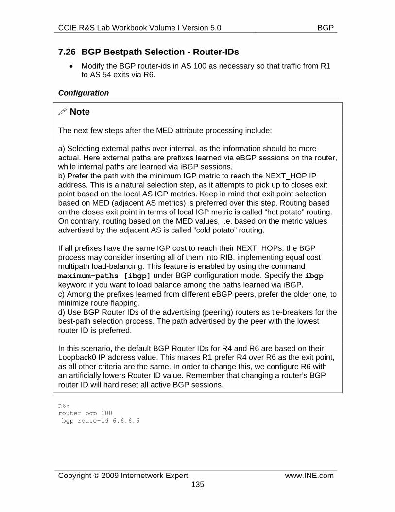
CCIE R&S Lab Workbook Volume I Version 5.0 BGP
Copyright © 2009 Internetwork Expert www.INE.com135
7.26 BGP Bestpath Selection - Router-IDs • Modify the BGP router-ids in AS 100 as necessary so that traffic from R1
to AS 54 exits via R6.
Configuration
Note
The next few steps after the MED attribute processing include:
a) Selecting external paths over internal, as the information should be more actual. Here external paths are prefixes learned via eBGP sessions on the router, while internal paths are learned via iBGP sessions. b) Prefer the path with the minimum IGP metric to reach the NEXT_HOP IP address. This is a natural selection step, as it attempts to pick up to closes exit point based on the local AS IGP metrics. Keep in mind that exit point selection based on MED (adjacent AS metrics) is preferred over this step. Routing based on the closes exit point in terms of local IGP metric is called “hot potato” routing. On contrary, routing based on the MED values, i.e. based on the metric values advertised by the adjacent AS is called “cold potato” routing.
If all prefixes have the same IGP cost to reach their NEXT_HOPs, the BGP process may consider inserting all of them into RIB, implementing equal cost multipath load-balancing. This feature is enabled by using the command maximum-paths [ibgp] under BGP configuration mode. Specify the ibgpkeyword if you want to load balance among the paths learned via iBGP. c) Among the prefixes learned from different eBGP peers, prefer the older one, to minimize route flapping. d) Use BGP Router IDs of the advertising (peering) routers as tie-breakers for the best-path selection process. The path advertised by the peer with the lowest router ID is preferred.
In this scenario, the default BGP Router IDs for R4 and R6 are based on their Loopback0 IP address value. This makes R1 prefer R4 over R6 as the exit point, as all other criteria are the same. In order to change this, we configure R6 with an artificially lowers Router ID value. Remember that changing a router’s BGP router ID will hard reset all active BGP sessions.
R6: router bgp 100 bgp route-id 6.6.6.6
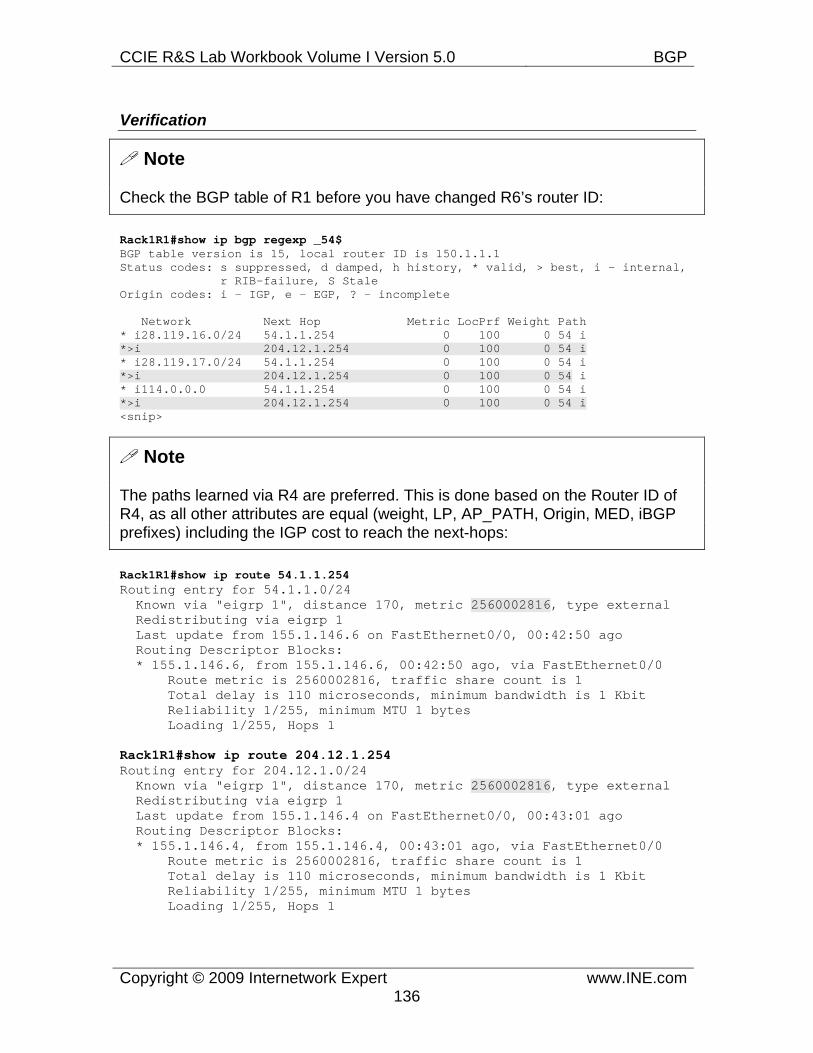
CCIE R&S Lab Workbook Volume I Version 5.0 BGP
Copyright © 2009 Internetwork Expert www.INE.com136
Verification
Note
Check the BGP table of R1 before you have changed R6’s router ID:
Rack1R1#show ip bgp regexp _54$ BGP table version is 15, local router ID is 150.1.1.1 Status codes: s suppressed, d damped, h history, * valid, > best, i - internal, r RIB-failure, S Stale Origin codes: i - IGP, e - EGP, ? - incomplete
Network Next Hop Metric LocPrf Weight Path * i28.119.16.0/24 54.1.1.254 0 100 0 54 i *>i 204.12.1.254 0 100 0 54 i * i28.119.17.0/24 54.1.1.254 0 100 0 54 i *>i 204.12.1.254 0 100 0 54 i * i114.0.0.0 54.1.1.254 0 100 0 54 i *>i 204.12.1.254 0 100 0 54 i <snip>
Note
The paths learned via R4 are preferred. This is done based on the Router ID of R4, as all other attributes are equal (weight, LP, AP_PATH, Origin, MED, iBGP prefixes) including the IGP cost to reach the next-hops:
Rack1R1#show ip route 54.1.1.254 Routing entry for 54.1.1.0/24 Known via "eigrp 1", distance 170, metric 2560002816, type external Redistributing via eigrp 1 Last update from 155.1.146.6 on FastEthernet0/0, 00:42:50 ago Routing Descriptor Blocks: * 155.1.146.6, from 155.1.146.6, 00:42:50 ago, via FastEthernet0/0 Route metric is 2560002816, traffic share count is 1 Total delay is 110 microseconds, minimum bandwidth is 1 Kbit Reliability 1/255, minimum MTU 1 bytes Loading 1/255, Hops 1
Rack1R1#show ip route 204.12.1.254 Routing entry for 204.12.1.0/24 Known via "eigrp 1", distance 170, metric 2560002816, type external Redistributing via eigrp 1 Last update from 155.1.146.4 on FastEthernet0/0, 00:43:01 ago Routing Descriptor Blocks: * 155.1.146.4, from 155.1.146.4, 00:43:01 ago, via FastEthernet0/0 Route metric is 2560002816, traffic share count is 1 Total delay is 110 microseconds, minimum bandwidth is 1 Kbit Reliability 1/255, minimum MTU 1 bytes Loading 1/255, Hops 1
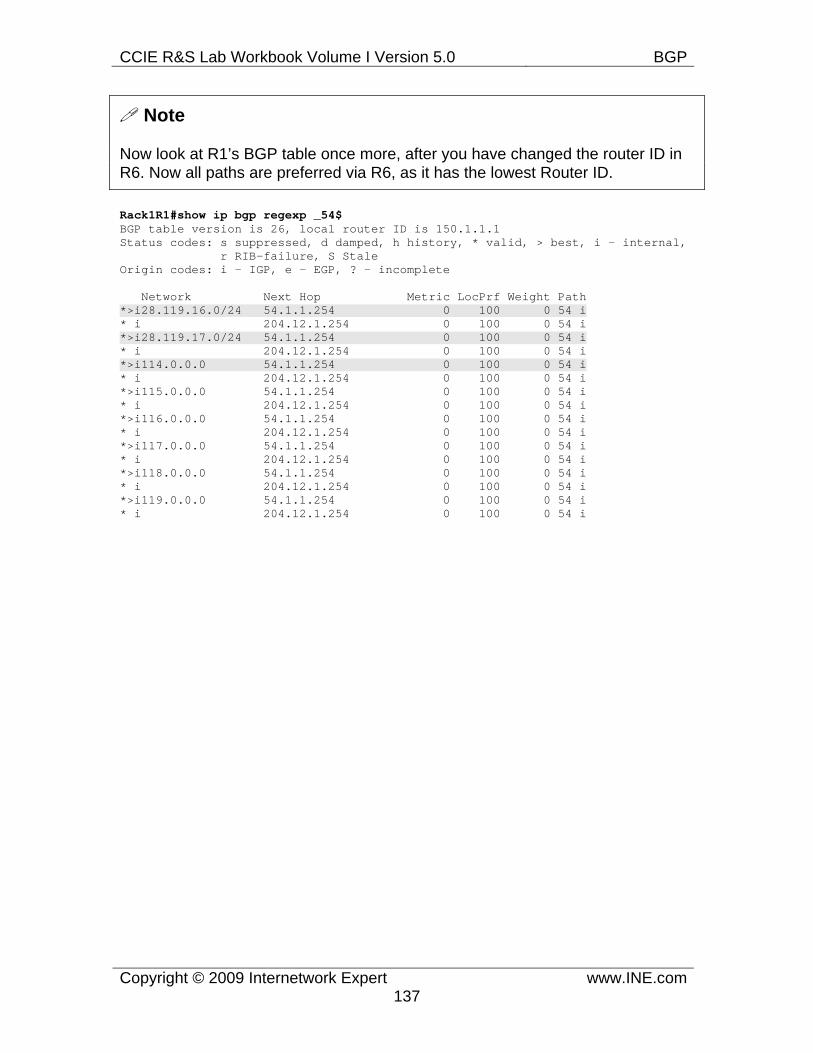
CCIE R&S Lab Workbook Volume I Version 5.0 BGP
Copyright © 2009 Internetwork Expert www.INE.com137
Note
Now look at R1’s BGP table once more, after you have changed the router ID in R6. Now all paths are preferred via R6, as it has the lowest Router ID.
Rack1R1#show ip bgp regexp _54$ BGP table version is 26, local router ID is 150.1.1.1 Status codes: s suppressed, d damped, h history, * valid, > best, i - internal, r RIB-failure, S Stale Origin codes: i - IGP, e - EGP, ? - incomplete
Network Next Hop Metric LocPrf Weight Path *>i28.119.16.0/24 54.1.1.254 0 100 0 54 i * i 204.12.1.254 0 100 0 54 i *>i28.119.17.0/24 54.1.1.254 0 100 0 54 i * i 204.12.1.254 0 100 0 54 i *>i114.0.0.0 54.1.1.254 0 100 0 54 i * i 204.12.1.254 0 100 0 54 i *>i115.0.0.0 54.1.1.254 0 100 0 54 i * i 204.12.1.254 0 100 0 54 i *>i116.0.0.0 54.1.1.254 0 100 0 54 i * i 204.12.1.254 0 100 0 54 i *>i117.0.0.0 54.1.1.254 0 100 0 54 i * i 204.12.1.254 0 100 0 54 i *>i118.0.0.0 54.1.1.254 0 100 0 54 i * i 204.12.1.254 0 100 0 54 i *>i119.0.0.0 54.1.1.254 0 100 0 54 i * i 204.12.1.254 0 100 0 54 i
CCIE R&S Lab Workbook Volume I Version 5.0 BGP
Copyright © 2009 Internetwork Expert www.INE.com138
7.27 BGP Bestpath Selection - DMZ Link Bandwidth • Modify the configuration of AS 100 routers so that R1 load-balances to the
paths in AS 54 proportional to the bandwidth of the links connecting R4 and R6 to AS 54 routers.
Configuration
Note
As mentioned in the previous tasks, local BGP process may implement equal-cost load-balancing to the paths that have:
1) The same set of path attributes up to the MED, i.e. weight, Local Preference, Origin, MED 2) Are of the same type, i.e. both learned via iBGP or eBGP 3) Have the same IGP cost to reach their NEXT_HOP IP address.
If the above conditions are met and maximum-paths [ibgp] is configured under the BGP process, then BGP will install multiple equal-cost routes into the local RIB and use them for load-balancing. We call the above condition as load-balancing conditions for BGP.
BGP also implements unique unequal-cost load balancing feature. As you remember, unequal-cost load balancing could not be implemented easily with any IGP. The protocol needs a way to ensure that all alternative paths are loop-free. So far only EIGRP support this feature, since all alternate unequal cost paths are guaranteed to be loop free by the virtue of feasible successor property. As for BGP, it ensures loop-free property for any routes learned via eBGP, based on the duplicate AS number detection. Thus, it is possible to implement unequal cost load-balancing in BGP toward the prefixes learned from other ASes.
This feature is called DMZ Link Bandwidth in IOS. The rationale behind this name is that load-balancing is based on the bandwidth of the links connecting the border BGP peers to their neighbors. Here is how it works for a single router with multiple eBGP peering links:
1) You enable the feature in a border BGP router using the command bgp dmzlink-bw. With this command enabled, the BGP process will instruct the data plane to load-balance based on the bandwidth of the links used to connect to the external BGP peers.In order to select the links that are to be used for load-balancing, you configure the respective BGP peers using the command neighbor <IP> dmzlink-bw. The BGP process will take the bandwidth on the links connecting to those peers in consideration when doing the unequal cost load-balancing. Those links are called the DMZ Links in Cisco terminology. The bandwidth is computed based on the bandwidth command configured on the
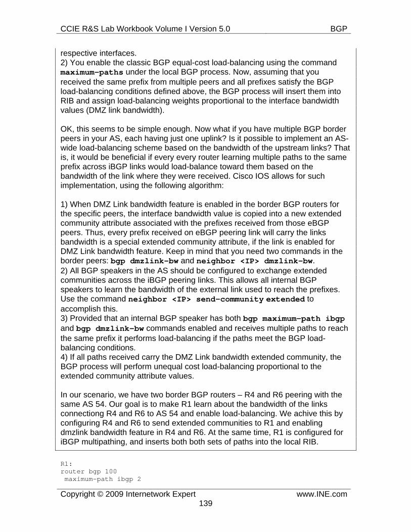
CCIE R&S Lab Workbook Volume I Version 5.0 BGP
Copyright © 2009 Internetwork Expert www.INE.com139
respective interfaces. 2) You enable the classic BGP equal-cost load-balancing using the command maximum-paths under the local BGP process. Now, assuming that you received the same prefix from multiple peers and all prefixes satisfy the BGP load-balancing conditions defined above, the BGP process will insert them into RIB and assign load-balancing weights proportional to the interface bandwidth values (DMZ link bandwidth).
OK, this seems to be simple enough. Now what if you have multiple BGP border peers in your AS, each having just one uplink? Is it possible to implement an AS-wide load-balancing scheme based on the bandwidth of the upstream links? That is, it would be beneficial if every every router learning multiple paths to the same prefix across iBGP links would load-balance toward them based on the bandwidth of the link where they were received. Cisco IOS allows for such implementation, using the following algorithm:
1) When DMZ Link bandwidth feature is enabled in the border BGP routers for the specific peers, the interface bandwidth value is copied into a new extended community attribute associated with the prefixes received from those eBGP peers. Thus, every prefix received on eBGP peering link will carry the links bandwidth is a special extended community attribute, if the link is enabled for DMZ Link bandwidth feature. Keep in mind that you need two commands in the border peers: bgp dmzlink-bw and neighbor <IP> dmzlink-bw. 2) All BGP speakers in the AS should be configured to exchange extended communities across the iBGP peering links. This allows all internal BGP speakers to learn the bandwidth of the external link used to reach the prefixes. Use the command neighbor <IP> send-community extended to accomplish this. 3) Provided that an internal BGP speaker has both bgp maximum-path ibgpand bgp dmzlink-bw commands enabled and receives multiple paths to reach the same prefix it performs load-balancing if the paths meet the BGP load-balancing conditions. 4) If all paths received carry the DMZ Link bandwidth extended community, the BGP process will perform unequal cost load-balancing proportional to the extended community attribute values.
In our scenario, we have two border BGP routers – R4 and R6 peering with the same AS 54. Our goal is to make R1 learn about the bandwidth of the links connectiong R4 and R6 to AS 54 and enable load-balancing. We achive this by configuring R4 and R6 to send extended communities to R1 and enabling dmzlink bandwidth feature in R4 and R6. At the same time, R1 is configured for iBGP multipathing, and inserts both both sets of paths into the local RIB.
R1: router bgp 100 maximum-path ibgp 2
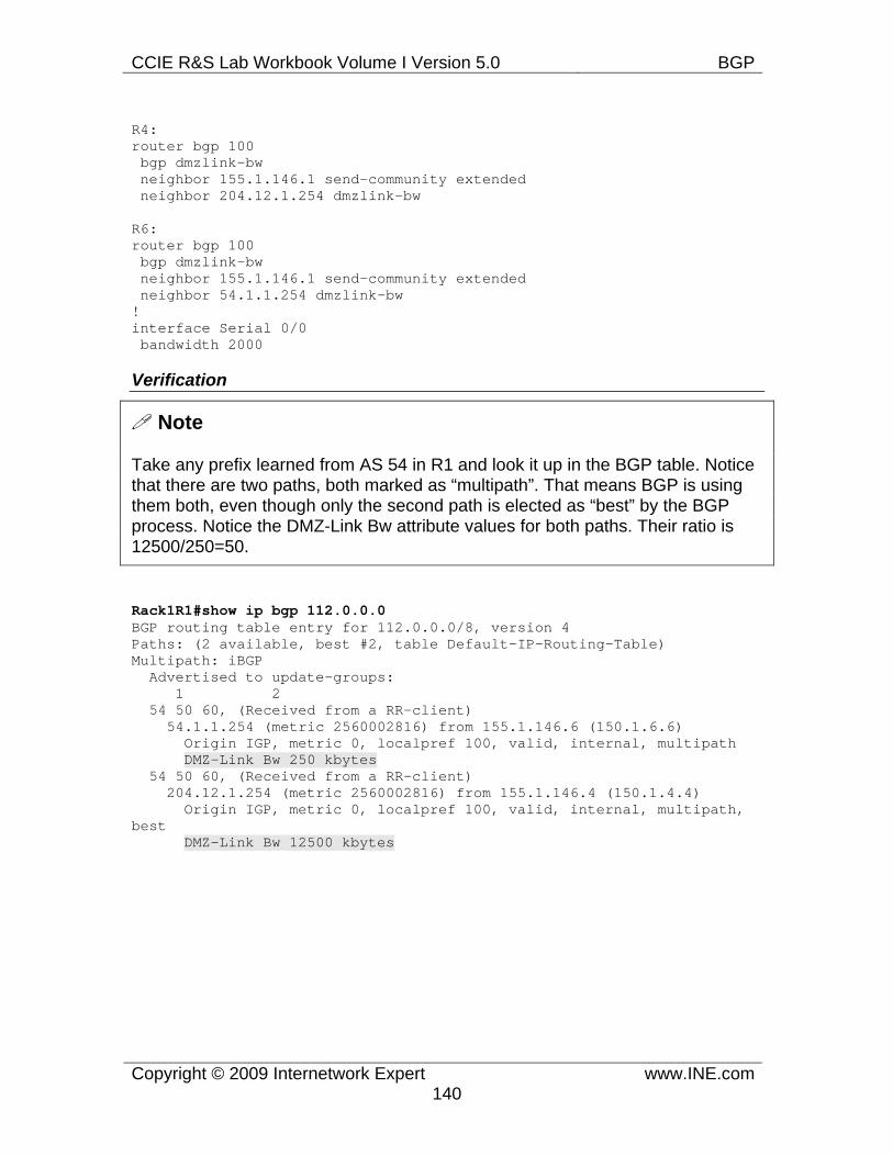
CCIE R&S Lab Workbook Volume I Version 5.0 BGP
Copyright © 2009 Internetwork Expert www.INE.com140
R4: router bgp 100 bgp dmzlink-bw neighbor 155.1.146.1 send-community extended neighbor 204.12.1.254 dmzlink-bw
R6: router bgp 100 bgp dmzlink-bw neighbor 155.1.146.1 send-community extended neighbor 54.1.1.254 dmzlink-bw ! interface Serial 0/0 bandwidth 2000
Verification
Note
Take any prefix learned from AS 54 in R1 and look it up in the BGP table. Notice that there are two paths, both marked as “multipath”. That means BGP is using them both, even though only the second path is elected as “best” by the BGP process. Notice the DMZ-Link Bw attribute values for both paths. Their ratio is 12500/250=50.
Rack1R1#show ip bgp 112.0.0.0 BGP routing table entry for 112.0.0.0/8, version 4 Paths: (2 available, best #2, table Default-IP-Routing-Table) Multipath: iBGP Advertised to update-groups: 1 2 54 50 60, (Received from a RR-client) 54.1.1.254 (metric 2560002816) from 155.1.146.6 (150.1.6.6) Origin IGP, metric 0, localpref 100, valid, internal, multipath DMZ-Link Bw 250 kbytes 54 50 60, (Received from a RR-client) 204.12.1.254 (metric 2560002816) from 155.1.146.4 (150.1.4.4) Origin IGP, metric 0, localpref 100, valid, internal, multipath, best DMZ-Link Bw 12500 kbytes
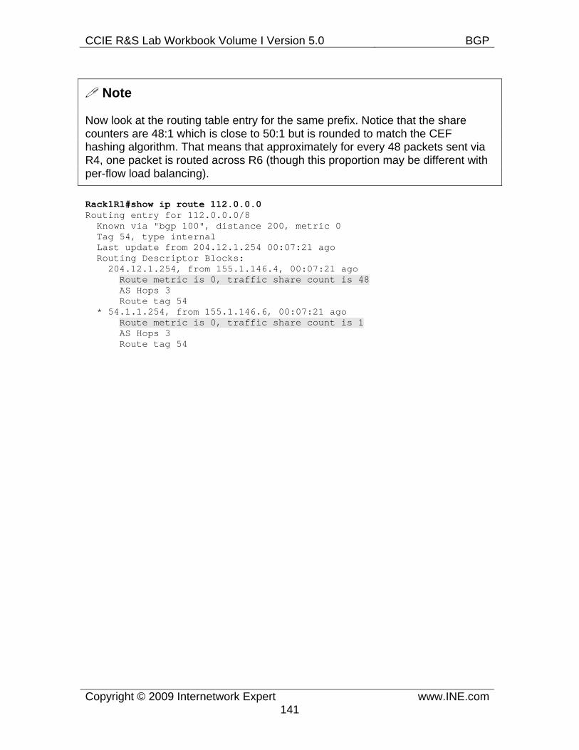
CCIE R&S Lab Workbook Volume I Version 5.0 BGP
Copyright © 2009 Internetwork Expert www.INE.com141
Note
Now look at the routing table entry for the same prefix. Notice that the share counters are 48:1 which is close to 50:1 but is rounded to match the CEF hashing algorithm. That means that approximately for every 48 packets sent via R4, one packet is routed across R6 (though this proportion may be different with per-flow load balancing).
Rack1R1#show ip route 112.0.0.0 Routing entry for 112.0.0.0/8 Known via "bgp 100", distance 200, metric 0 Tag 54, type internal Last update from 204.12.1.254 00:07:21 ago Routing Descriptor Blocks: 204.12.1.254, from 155.1.146.4, 00:07:21 ago Route metric is 0, traffic share count is 48 AS Hops 3 Route tag 54 * 54.1.1.254, from 155.1.146.6, 00:07:21 ago Route metric is 0, traffic share count is 1 AS Hops 3 Route tag 54
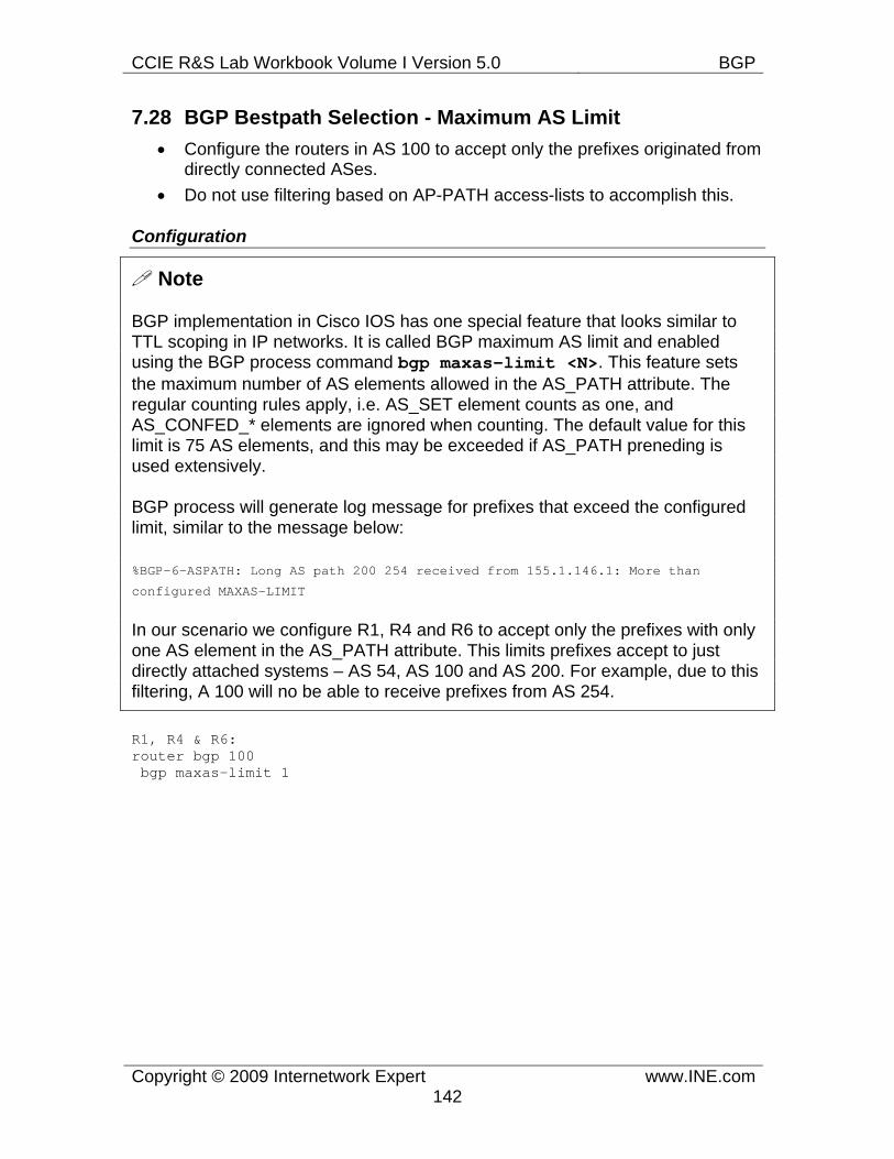
CCIE R&S Lab Workbook Volume I Version 5.0 BGP
Copyright © 2009 Internetwork Expert www.INE.com142
7.28 BGP Bestpath Selection - Maximum AS Limit • Configure the routers in AS 100 to accept only the prefixes originated from
directly connected ASes. • Do not use filtering based on AP-PATH access-lists to accomplish this.
Configuration
Note
BGP implementation in Cisco IOS has one special feature that looks similar to TTL scoping in IP networks. It is called BGP maximum AS limit and enabled using the BGP process command bgp maxas-limit <N>. This feature sets the maximum number of AS elements allowed in the AS_PATH attribute. The regular counting rules apply, i.e. AS_SET element counts as one, and AS_CONFED_* elements are ignored when counting. The default value for this limit is 75 AS elements, and this may be exceeded if AS_PATH preneding is used extensively.
BGP process will generate log message for prefixes that exceed the configured limit, similar to the message below:
%BGP-6-ASPATH: Long AS path 200 254 received from 155.1.146.1: More than
configured MAXAS-LIMIT
In our scenario we configure R1, R4 and R6 to accept only the prefixes with only one AS element in the AS_PATH attribute. This limits prefixes accept to just directly attached systems – AS 54, AS 100 and AS 200. For example, due to this filtering, A 100 will no be able to receive prefixes from AS 254.
R1, R4 & R6: router bgp 100 bgp maxas-limit 1
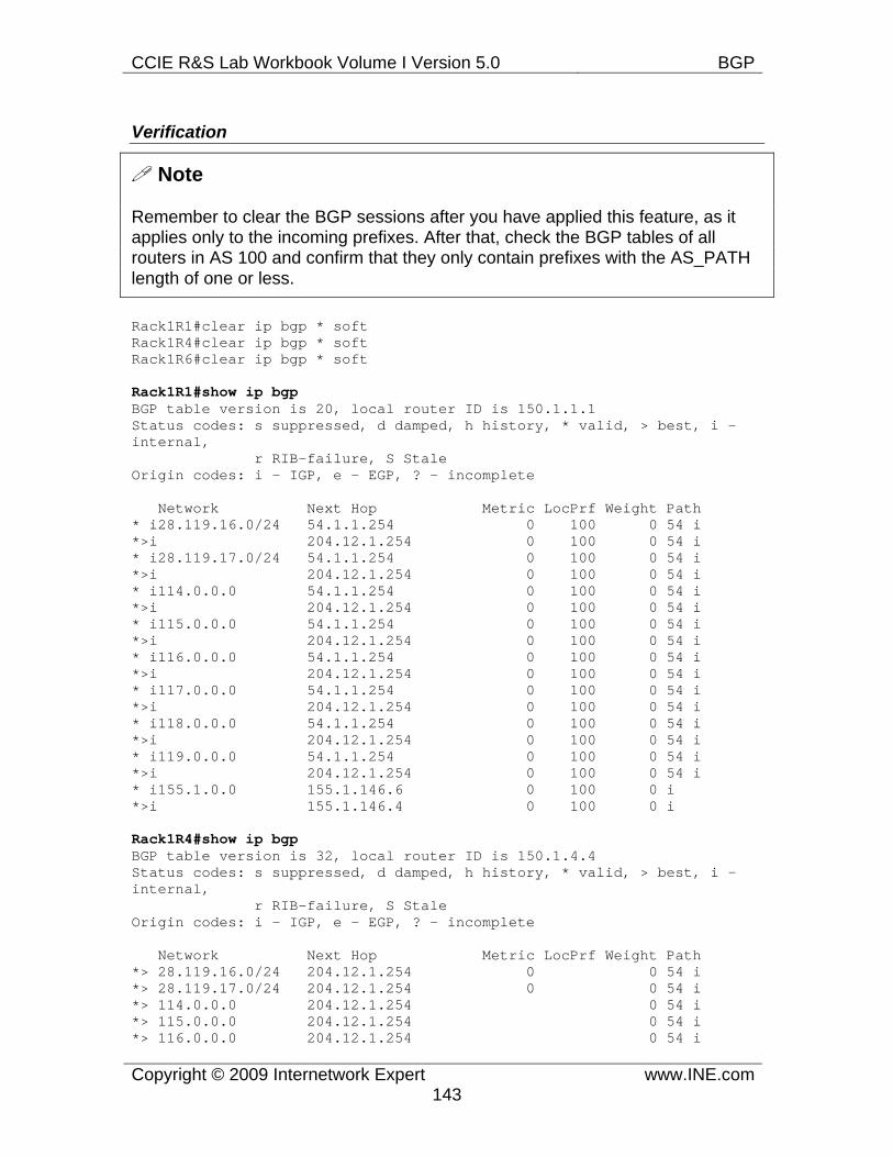
CCIE R&S Lab Workbook Volume I Version 5.0 BGP
Copyright © 2009 Internetwork Expert www.INE.com143
Verification
Note
Remember to clear the BGP sessions after you have applied this feature, as it applies only to the incoming prefixes. After that, check the BGP tables of all routers in AS 100 and confirm that they only contain prefixes with the AS_PATH length of one or less.
Rack1R1#clear ip bgp * soft Rack1R4#clear ip bgp * soft Rack1R6#clear ip bgp * soft
Rack1R1#show ip bgp BGP table version is 20, local router ID is 150.1.1.1 Status codes: s suppressed, d damped, h history, * valid, > best, i - internal, r RIB-failure, S Stale Origin codes: i - IGP, e - EGP, ? - incomplete
Network Next Hop Metric LocPrf Weight Path * i28.119.16.0/24 54.1.1.254 0 100 0 54 i *>i 204.12.1.254 0 100 0 54 i * i28.119.17.0/24 54.1.1.254 0 100 0 54 i *>i 204.12.1.254 0 100 0 54 i * i114.0.0.0 54.1.1.254 0 100 0 54 i *>i 204.12.1.254 0 100 0 54 i * i115.0.0.0 54.1.1.254 0 100 0 54 i *>i 204.12.1.254 0 100 0 54 i * i116.0.0.0 54.1.1.254 0 100 0 54 i *>i 204.12.1.254 0 100 0 54 i * i117.0.0.0 54.1.1.254 0 100 0 54 i *>i 204.12.1.254 0 100 0 54 i * i118.0.0.0 54.1.1.254 0 100 0 54 i *>i 204.12.1.254 0 100 0 54 i * i119.0.0.0 54.1.1.254 0 100 0 54 i *>i 204.12.1.254 0 100 0 54 i * i155.1.0.0 155.1.146.6 0 100 0 i *>i 155.1.146.4 0 100 0 i
Rack1R4#show ip bgp BGP table version is 32, local router ID is 150.1.4.4 Status codes: s suppressed, d damped, h history, * valid, > best, i - internal, r RIB-failure, S Stale Origin codes: i - IGP, e - EGP, ? - incomplete
Network Next Hop Metric LocPrf Weight Path *> 28.119.16.0/24 204.12.1.254 0 0 54 i *> 28.119.17.0/24 204.12.1.254 0 0 54 i *> 114.0.0.0 204.12.1.254 0 54 i *> 115.0.0.0 204.12.1.254 0 54 i *> 116.0.0.0 204.12.1.254 0 54 i
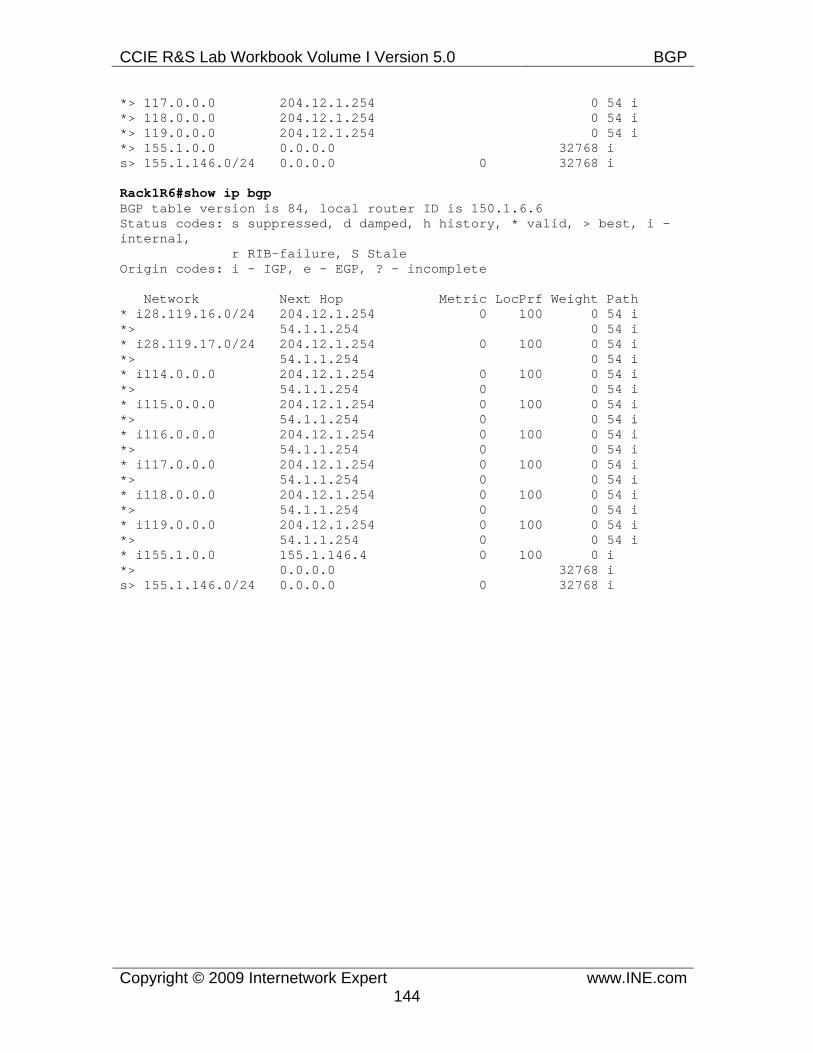
CCIE R&S Lab Workbook Volume I Version 5.0 BGP
Copyright © 2009 Internetwork Expert www.INE.com144
*> 117.0.0.0 204.12.1.254 0 54 i *> 118.0.0.0 204.12.1.254 0 54 i *> 119.0.0.0 204.12.1.254 0 54 i *> 155.1.0.0 0.0.0.0 32768 i s> 155.1.146.0/24 0.0.0.0 0 32768 i
Rack1R6#show ip bgp BGP table version is 84, local router ID is 150.1.6.6 Status codes: s suppressed, d damped, h history, * valid, > best, i - internal, r RIB-failure, S Stale Origin codes: i - IGP, e - EGP, ? - incomplete
Network Next Hop Metric LocPrf Weight Path * i28.119.16.0/24 204.12.1.254 0 100 0 54 i *> 54.1.1.254 0 54 i * i28.119.17.0/24 204.12.1.254 0 100 0 54 i *> 54.1.1.254 0 54 i * i114.0.0.0 204.12.1.254 0 100 0 54 i *> 54.1.1.254 0 0 54 i * i115.0.0.0 204.12.1.254 0 100 0 54 i *> 54.1.1.254 0 0 54 i * i116.0.0.0 204.12.1.254 0 100 0 54 i *> 54.1.1.254 0 0 54 i * i117.0.0.0 204.12.1.254 0 100 0 54 i *> 54.1.1.254 0 0 54 i * i118.0.0.0 204.12.1.254 0 100 0 54 i *> 54.1.1.254 0 0 54 i * i119.0.0.0 204.12.1.254 0 100 0 54 i *> 54.1.1.254 0 0 54 i * i155.1.0.0 155.1.146.4 0 100 0 i *> 0.0.0.0 32768 i s> 155.1.146.0/24 0.0.0.0 0 32768 i
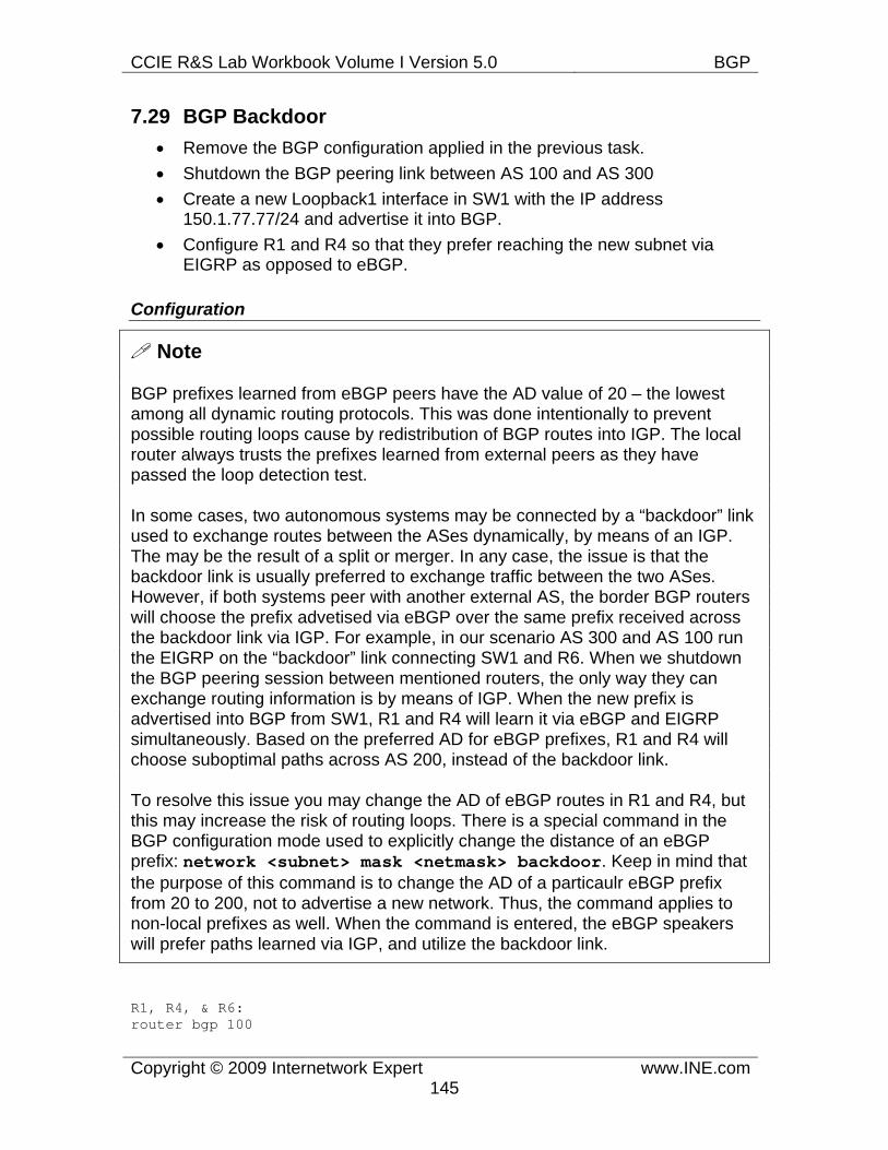
CCIE R&S Lab Workbook Volume I Version 5.0 BGP
Copyright © 2009 Internetwork Expert www.INE.com145
7.29 BGP Backdoor • Remove the BGP configuration applied in the previous task. • Shutdown the BGP peering link between AS 100 and AS 300 • Create a new Loopback1 interface in SW1 with the IP address
150.1.77.77/24 and advertise it into BGP. • Configure R1 and R4 so that they prefer reaching the new subnet via
EIGRP as opposed to eBGP.
Configuration
Note
BGP prefixes learned from eBGP peers have the AD value of 20 – the lowest among all dynamic routing protocols. This was done intentionally to prevent possible routing loops cause by redistribution of BGP routes into IGP. The local router always trusts the prefixes learned from external peers as they have passed the loop detection test.
In some cases, two autonomous systems may be connected by a “backdoor” link used to exchange routes between the ASes dynamically, by means of an IGP. The may be the result of a split or merger. In any case, the issue is that the backdoor link is usually preferred to exchange traffic between the two ASes. However, if both systems peer with another external AS, the border BGP routers will choose the prefix advetised via eBGP over the same prefix received across the backdoor link via IGP. For example, in our scenario AS 300 and AS 100 run the EIGRP on the “backdoor” link connecting SW1 and R6. When we shutdown the BGP peering session between mentioned routers, the only way they can exchange routing information is by means of IGP. When the new prefix is advertised into BGP from SW1, R1 and R4 will learn it via eBGP and EIGRP simultaneously. Based on the preferred AD for eBGP prefixes, R1 and R4 will choose suboptimal paths across AS 200, instead of the backdoor link.
To resolve this issue you may change the AD of eBGP routes in R1 and R4, but this may increase the risk of routing loops. There is a special command in the BGP configuration mode used to explicitly change the distance of an eBGP prefix: network <subnet> mask <netmask> backdoor. Keep in mind that the purpose of this command is to change the AD of a particaulr eBGP prefix from 20 to 200, not to advertise a new network. Thus, the command applies to non-local prefixes as well. When the command is entered, the eBGP speakers will prefer paths learned via IGP, and utilize the backdoor link.
R1, R4, & R6: router bgp 100
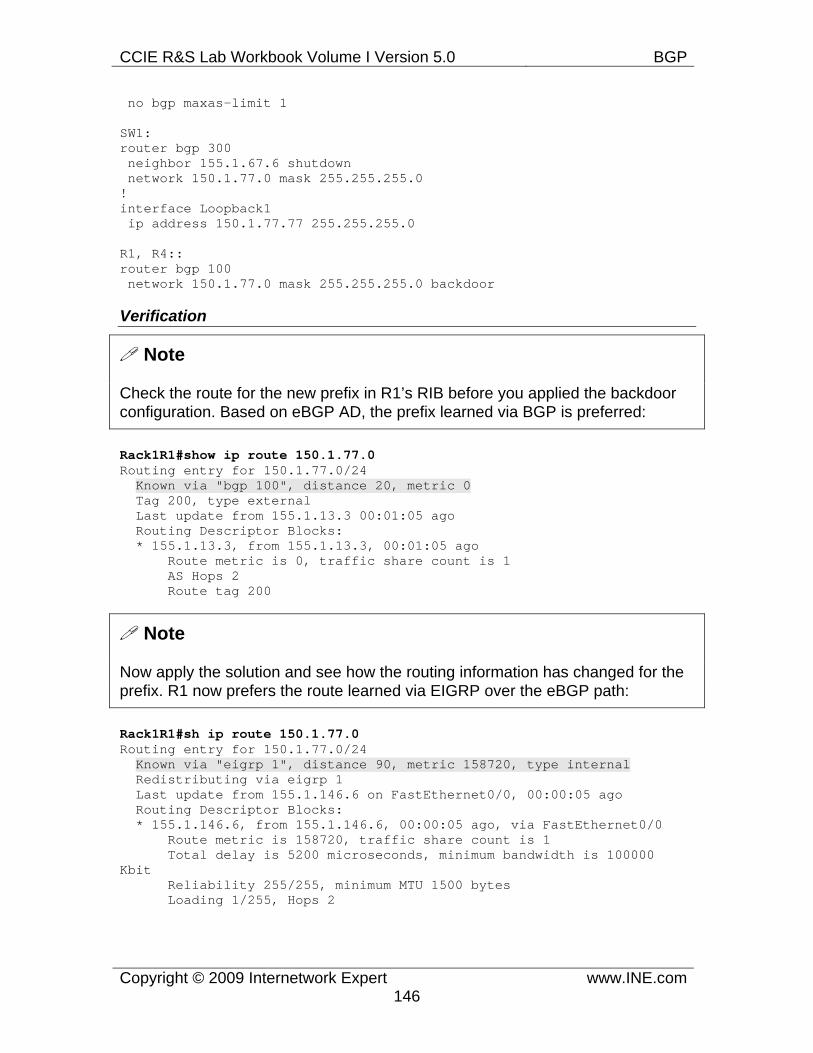
CCIE R&S Lab Workbook Volume I Version 5.0 BGP
Copyright © 2009 Internetwork Expert www.INE.com146
no bgp maxas-limit 1
SW1: router bgp 300 neighbor 155.1.67.6 shutdown network 150.1.77.0 mask 255.255.255.0 ! interface Loopback1 ip address 150.1.77.77 255.255.255.0
R1, R4:: router bgp 100 network 150.1.77.0 mask 255.255.255.0 backdoor
Verification
Note
Check the route for the new prefix in R1’s RIB before you applied the backdoor configuration. Based on eBGP AD, the prefix learned via BGP is preferred:
Rack1R1#show ip route 150.1.77.0 Routing entry for 150.1.77.0/24 Known via "bgp 100", distance 20, metric 0 Tag 200, type external Last update from 155.1.13.3 00:01:05 ago Routing Descriptor Blocks: * 155.1.13.3, from 155.1.13.3, 00:01:05 ago Route metric is 0, traffic share count is 1 AS Hops 2 Route tag 200
Note
Now apply the solution and see how the routing information has changed for the prefix. R1 now prefers the route learned via EIGRP over the eBGP path:
Rack1R1#sh ip route 150.1.77.0 Routing entry for 150.1.77.0/24 Known via "eigrp 1", distance 90, metric 158720, type internal Redistributing via eigrp 1 Last update from 155.1.146.6 on FastEthernet0/0, 00:00:05 ago Routing Descriptor Blocks: * 155.1.146.6, from 155.1.146.6, 00:00:05 ago, via FastEthernet0/0 Route metric is 158720, traffic share count is 1 Total delay is 5200 microseconds, minimum bandwidth is 100000 Kbit Reliability 255/255, minimum MTU 1500 bytes Loading 1/255, Hops 2
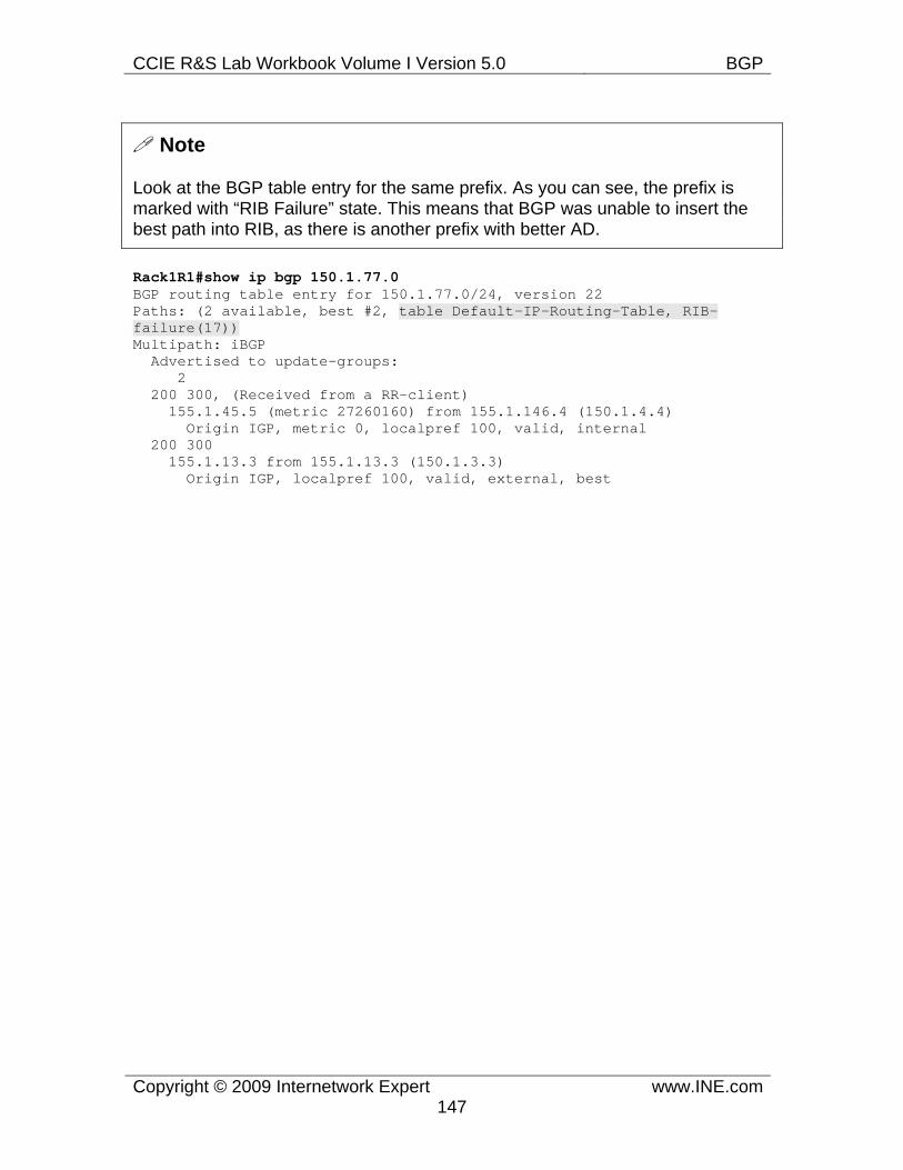
CCIE R&S Lab Workbook Volume I Version 5.0 BGP
Copyright © 2009 Internetwork Expert www.INE.com147
Note
Look at the BGP table entry for the same prefix. As you can see, the prefix is marked with “RIB Failure” state. This means that BGP was unable to insert the best path into RIB, as there is another prefix with better AD.
Rack1R1#show ip bgp 150.1.77.0 BGP routing table entry for 150.1.77.0/24, version 22 Paths: (2 available, best #2, table Default-IP-Routing-Table, RIB-failure(17)) Multipath: iBGP Advertised to update-groups: 2 200 300, (Received from a RR-client) 155.1.45.5 (metric 27260160) from 155.1.146.4 (150.1.4.4) Origin IGP, metric 0, localpref 100, valid, internal 200 300 155.1.13.3 from 155.1.13.3 (150.1.3.3) Origin IGP, localpref 100, valid, external, best
CCIE R&S Lab Workbook Volume I Version 5.0 BGP
Copyright © 2009 Internetwork Expert www.INE.com148
7.30 BGP Aggregation • Remove the BGP configuration made for the previous task. • Configure R2 with four new Loopback interfaces with the IP addresses
10.0.0.1/24, 10.0.1.1/24, 10.0.2.1/24, and 10.0.3.1/24. • Advertise an aggregate route for these networks that does not overlap any
address space.
Configuration
Note
Route aggregation is the key for information hiding. It is critical to BGP due to the tremendous amount of routing information passed on the Internet. There are three basic ways to do summarization in BGP:
1) Create a summary prefix in IGP and advertise it into BGP using the networkcommand. Most often this is accomplished by creating a static route to Null0 in the routing table of the advertising router. This is a common way to advertise local prefixes into BGP. However, you cannot summarize external BGP prefixes using the method. 2) Auto-summarization. As discussed in the separate task, summarizes networks to their classful boundaries. Only applies to redistributed prefixes or when using the classful network command. Not used in modern networks. 3) Summarization of prefixes found in BGP tables using the aggregate-address command. This is the most flexible way to do summarization, as it may be applied to any paths learned by the BGP speaker.
Through the next few tasks we are going to work with the last command. It has many options, and its unique feature is that is allows manipulating BGP attributes when aggregating prefixes. In the simplest form, the syntax for the command is aggregate-address <prefix> <mask>. In order for the command to work, there mask be a subnet in the BGP table that is encompassed by the summarized prefix. For example, if you issue the command aggregate-address 192.168.0.0 255.255.0.0 then at least one subnet like 192.168.1.0/24 must be in the BGP table (Loc-RIB) and not the router’s routing table (RIB).
If you didn’t specify any additional options to the command, it will create a new prefix in the BGP table, with an empty AS_PATH. It would look like the new prefix was originated in the local AS. The new prefix will automatically have the weight value of 32768 and get a special attribute called ATOMIC_AGGREGATE assigned. The new attribute is informational, and tells the other BGP speakers that this prefix is a result of route aggregation and some information (like AS_PATH or other attributes) from the original prefixes may be missing. In
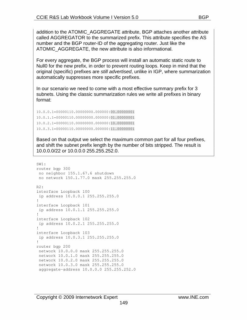
CCIE R&S Lab Workbook Volume I Version 5.0 BGP
Copyright © 2009 Internetwork Expert www.INE.com149
addition to the ATOMIC_AGGREGATE attribute, BGP attaches another attribute called AGGREGATOR to the summarized prefix. This attribute specifies the AS number and the BGP router-ID of the aggregating router. Just like the ATOMIC_AGGREGATE, the new attribute is also informational.
For every aggregate, the BGP process will install an automatic static route to Null0 for the new prefix, in order to prevent routing loops. Keep in mind that the original (specific) prefixes are still advertised, unlike in IGP, where summarization automatically suppresses more specific prefixes.
In our scenario we need to come with a most effective summary prefix for 3 subnets. Using the classic summarization rules we write all prefixes in binary format:
10.0.0.1=00000110.00000000.000000|00.00000001
10.0.1.1=00000110.00000000.000000|01.00000001
10.0.2.1=00000110.00000000.000000|10.00000001
10.0.3.1=00000110.00000000.000000|11.00000001
Based on that output we select the maximum common part for all four prefixes, and shift the subnet prefix length by the number of bits stripped. The result is 10.0.0.0/22 or 10.0.0.0 255.255.252.0.
SW1: router bgp 300 no neighbor 155.1.67.6 shutdown no network 150.1.77.0 mask 255.255.255.0
R2: interface Loopback 100 ip address 10.0.0.1 255.255.255.0 ! interface Loopback 101 ip address 10.0.1.1 255.255.255.0 ! interface Loopback 102 ip address 10.0.2.1 255.255.255.0 ! interface Loopback 103 ip address 10.0.3.1 255.255.255.0 ! router bgp 200 network 10.0.0.0 mask 255.255.255.0 network 10.0.1.0 mask 255.255.255.0 network 10.0.2.0 mask 255.255.255.0 network 10.0.3.0 mask 255.255.255.0 aggregate-address 10.0.0.0 255.255.252.0
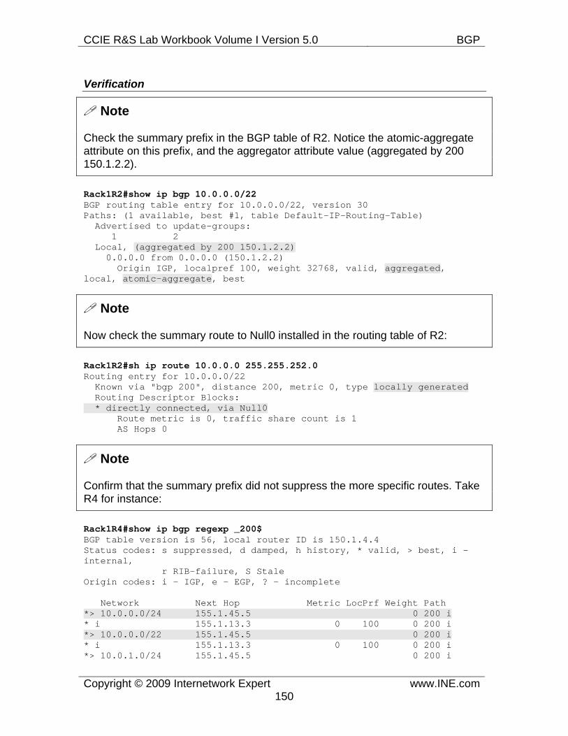
CCIE R&S Lab Workbook Volume I Version 5.0 BGP
Copyright © 2009 Internetwork Expert www.INE.com150
Verification
Note
Check the summary prefix in the BGP table of R2. Notice the atomic-aggregate attribute on this prefix, and the aggregator attribute value (aggregated by 200 150.1.2.2).
Rack1R2#show ip bgp 10.0.0.0/22 BGP routing table entry for 10.0.0.0/22, version 30 Paths: (1 available, best #1, table Default-IP-Routing-Table) Advertised to update-groups: 1 2 Local, (aggregated by 200 150.1.2.2) 0.0.0.0 from 0.0.0.0 (150.1.2.2) Origin IGP, localpref 100, weight 32768, valid, aggregated, local, atomic-aggregate, best
Note
Now check the summary route to Null0 installed in the routing table of R2:
Rack1R2#sh ip route 10.0.0.0 255.255.252.0 Routing entry for 10.0.0.0/22 Known via "bgp 200", distance 200, metric 0, type locally generated Routing Descriptor Blocks: * directly connected, via Null0 Route metric is 0, traffic share count is 1 AS Hops 0
Note
Confirm that the summary prefix did not suppress the more specific routes. Take R4 for instance:
Rack1R4#show ip bgp regexp _200$ BGP table version is 56, local router ID is 150.1.4.4 Status codes: s suppressed, d damped, h history, * valid, > best, i - internal, r RIB-failure, S Stale Origin codes: i - IGP, e - EGP, ? - incomplete
Network Next Hop Metric LocPrf Weight Path *> 10.0.0.0/24 155.1.45.5 0 200 i * i 155.1.13.3 0 100 0 200 i *> 10.0.0.0/22 155.1.45.5 0 200 i * i 155.1.13.3 0 100 0 200 i *> 10.0.1.0/24 155.1.45.5 0 200 i
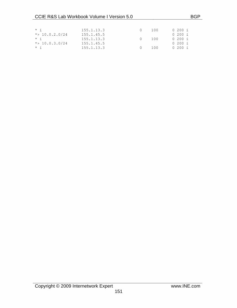
CCIE R&S Lab Workbook Volume I Version 5.0 BGP
Copyright © 2009 Internetwork Expert www.INE.com151
* i 155.1.13.3 0 100 0 200 i *> 10.0.2.0/24 155.1.45.5 0 200 i * i 155.1.13.3 0 100 0 200 i *> 10.0.3.0/24 155.1.45.5 0 200 i * i 155.1.13.3 0 100 0 200 i
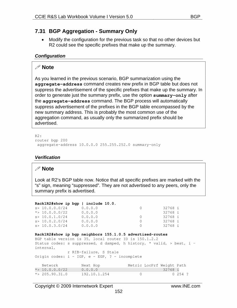
CCIE R&S Lab Workbook Volume I Version 5.0 BGP
Copyright © 2009 Internetwork Expert www.INE.com152
7.31 BGP Aggregation - Summary Only • Modify the configuration for the previous task so that no other devices but
R2 could see the specific prefixes that make up the summary.
Configuration
Note
As you learned in the previous scenario, BGP summarization using the aggregate-address command creates new prefix in BGP table but does not suppress the advertisement of the specific prefixes that make up the summary. In order to generate just the summary prefix, use the option summary-only after the aggregate-address command. The BGP process will automatically suppress advertisement of the prefixes in the BGP table encompassed by the new summary address. This is probably the most common use of the aggregation command, as usually only the summarized prefix should be advertised.
R2: router bgp 200 aggregate-address 10.0.0.0 255.255.252.0 summary-only
Verification
Note
Look at R2’s BGP table now. Notice that all specific prefixes are marked with the “s” sign, meaning “suppressed”. They are not advertised to any peers, only the summary prefix is advertised.
Rack1R2#show ip bgp | include 10.0. s> 10.0.0.0/24 0.0.0.0 0 32768 i *> 10.0.0.0/22 0.0.0.0 32768 i s> 10.0.1.0/24 0.0.0.0 0 32768 i s> 10.0.2.0/24 0.0.0.0 0 32768 i s> 10.0.3.0/24 0.0.0.0 0 32768 i
Rack1R2#show ip bgp neighbors 155.1.0.5 advertised-routes BGP table version is 35, local router ID is 150.1.2.2 Status codes: s suppressed, d damped, h history, * valid, > best, i - internal, r RIB-failure, S Stale Origin codes: i - IGP, e - EGP, ? - incomplete
Network Next Hop Metric LocPrf Weight Path *> 10.0.0.0/22 0.0.0.0 32768 i *> 205.90.31.0 192.10.1.254 0 0 254 ?
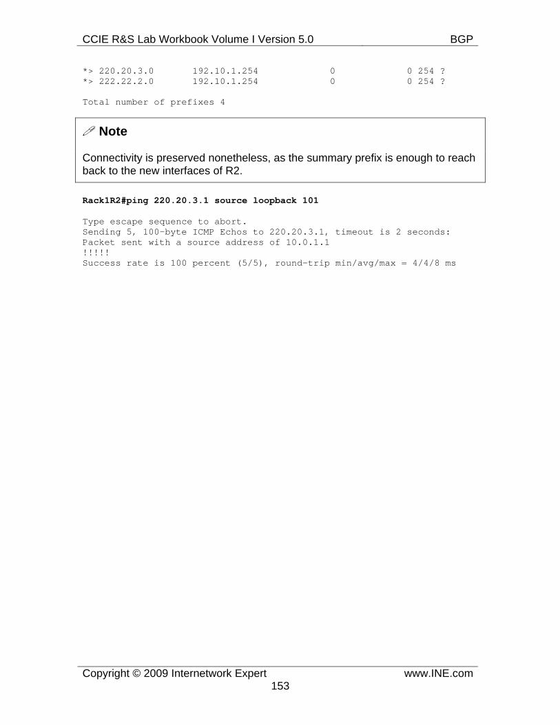
CCIE R&S Lab Workbook Volume I Version 5.0 BGP
Copyright © 2009 Internetwork Expert www.INE.com153
*> 220.20.3.0 192.10.1.254 0 0 254 ? *> 222.22.2.0 192.10.1.254 0 0 254 ?
Total number of prefixes 4
Note
Connectivity is preserved nonetheless, as the summary prefix is enough to reach back to the new interfaces of R2.
Rack1R2#ping 220.20.3.1 source loopback 101
Type escape sequence to abort. Sending 5, 100-byte ICMP Echos to 220.20.3.1, timeout is 2 seconds: Packet sent with a source address of 10.0.1.1 !!!!! Success rate is 100 percent (5/5), round-trip min/avg/max = 4/4/8 ms
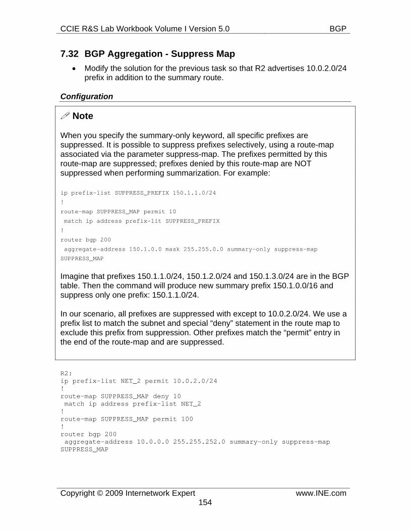
CCIE R&S Lab Workbook Volume I Version 5.0 BGP
Copyright © 2009 Internetwork Expert www.INE.com154
7.32 BGP Aggregation - Suppress Map • Modify the solution for the previous task so that R2 advertises 10.0.2.0/24
prefix in addition to the summary route.
Configuration
Note
When you specify the summary-only keyword, all specific prefixes are suppressed. It is possible to suppress prefixes selectively, using a route-map associated via the parameter suppress-map. The prefixes permitted by this route-map are suppressed; prefixes denied by this route-map are NOT suppressed when performing summarization. For example:
ip prefix-list SUPPRESS_PREFIX 150.1.1.0/24
!
route-map SUPPRESS_MAP permit 10
match ip address prefix-lit SUPPRESS_PREFIX
!
router bgp 200
aggregate-address 150.1.0.0 mask 255.255.0.0 summary-only suppress-map
SUPPRESS_MAP
Imagine that prefixes 150.1.1.0/24, 150.1.2.0/24 and 150.1.3.0/24 are in the BGP table. Then the command will produce new summary prefix 150.1.0.0/16 and suppress only one prefix: 150.1.1.0/24.
In our scenario, all prefixes are suppressed with except to 10.0.2.0/24. We use a prefix list to match the subnet and special “deny” statement in the route map to exclude this prefix from suppression. Other prefixes match the “permit” entry in the end of the route-map and are suppressed.
R2: ip prefix-list NET_2 permit 10.0.2.0/24 ! route-map SUPPRESS_MAP deny 10 match ip address prefix-list NET_2 ! route-map SUPPRESS_MAP permit 100 ! router bgp 200 aggregate-address 10.0.0.0 255.255.252.0 summary-only suppress-map SUPPRESS_MAP
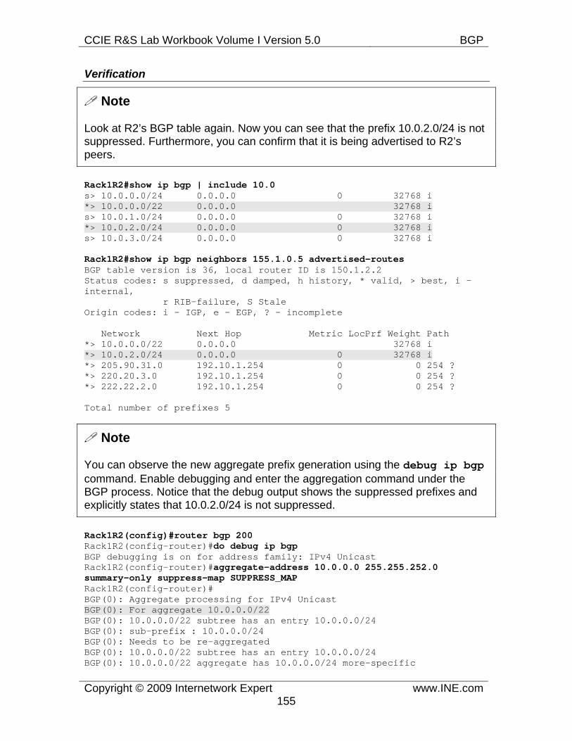
CCIE R&S Lab Workbook Volume I Version 5.0 BGP
Copyright © 2009 Internetwork Expert www.INE.com155
Verification
Note
Look at R2’s BGP table again. Now you can see that the prefix 10.0.2.0/24 is not suppressed. Furthermore, you can confirm that it is being advertised to R2’s peers.
Rack1R2#show ip bgp | include 10.0 s> 10.0.0.0/24 0.0.0.0 0 32768 i *> 10.0.0.0/22 0.0.0.0 32768 i s> 10.0.1.0/24 0.0.0.0 0 32768 i *> 10.0.2.0/24 0.0.0.0 0 32768 i s> 10.0.3.0/24 0.0.0.0 0 32768 i
Rack1R2#show ip bgp neighbors 155.1.0.5 advertised-routes BGP table version is 36, local router ID is 150.1.2.2 Status codes: s suppressed, d damped, h history, * valid, > best, i - internal, r RIB-failure, S Stale Origin codes: i - IGP, e - EGP, ? - incomplete
Network Next Hop Metric LocPrf Weight Path *> 10.0.0.0/22 0.0.0.0 32768 i *> 10.0.2.0/24 0.0.0.0 0 32768 i *> 205.90.31.0 192.10.1.254 0 0 254 ? *> 220.20.3.0 192.10.1.254 0 0 254 ? *> 222.22.2.0 192.10.1.254 0 0 254 ?
Total number of prefixes 5
Note
You can observe the new aggregate prefix generation using the debug ip bgpcommand. Enable debugging and enter the aggregation command under the BGP process. Notice that the debug output shows the suppressed prefixes and explicitly states that 10.0.2.0/24 is not suppressed.
Rack1R2(config)#router bgp 200 Rack1R2(config-router)#do debug ip bgp BGP debugging is on for address family: IPv4 Unicast Rack1R2(config-router)#aggregate-address 10.0.0.0 255.255.252.0 summary-only suppress-map SUPPRESS_MAPRack1R2(config-router)# BGP(0): Aggregate processing for IPv4 Unicast BGP(0): For aggregate 10.0.0.0/22 BGP(0): 10.0.0.0/22 subtree has an entry 10.0.0.0/24 BGP(0): sub-prefix : 10.0.0.0/24 BGP(0): Needs to be re-aggregated BGP(0): 10.0.0.0/22 subtree has an entry 10.0.0.0/24 BGP(0): 10.0.0.0/22 aggregate has 10.0.0.0/24 more-specific
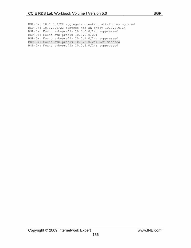
CCIE R&S Lab Workbook Volume I Version 5.0 BGP
Copyright © 2009 Internetwork Expert www.INE.com156
BGP(0): 10.0.0.0/22 aggregate created, attributes updated BGP(0): 10.0.0.0/22 subtree has an entry 10.0.0.0/24 BGP(0): Found sub-prefix 10.0.0.0/24: suppressed BGP(0): Found sub-prefix 10.0.0.0/22: BGP(0): Found sub-prefix 10.0.1.0/24: suppressed BGP(0): Found sub-prefix 10.0.2.0/24: Not matched BGP(0): Found sub-prefix 10.0.3.0/24: suppressed
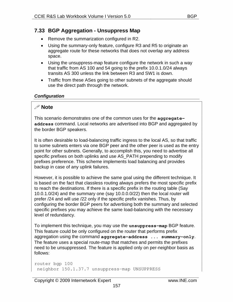
CCIE R&S Lab Workbook Volume I Version 5.0 BGP
Copyright © 2009 Internetwork Expert www.INE.com157
7.33 BGP Aggregation - Unsuppress Map • Remove the summarization configured in R2. • Using the summary-only feature, configure R3 and R5 to originate an
aggregate route for these networks that does not overlap any address space.
• Using the unsuppress-map feature configure the network in such a way that traffic from AS 100 and 54 going to the prefix 10.0.1.0/24 always transits AS 300 unless the link between R3 and SW1 is down.
• Traffic from these ASes going to other subnets of the aggregate should use the direct path through the network.
Configuration
Note
This scenario demonstrates one of the common uses for the aggregate-address command. Local networks are advertised into BGP and aggregated by the border BGP speakers.
It is often desirable to load-balancing traffic ingress to the local AS, so that traffic to some subnets enters via one BGP peer and the other peer is used as the entry point for other subnets. Generally, to accomplish this, you need to advertise all specific prefixes on both uplinks and use AS_PATH prepending to modify prefixes preference. This scheme implements load balancing and provides backup in case of any uplink failures.
However, it is possible to achieve the same goal using the different technique. It is based on the fact that classless routing always prefers the most specific prefix to reach the destinations. If there is a specific prefix in the routing table (Say 10.0.1.0/24) and the summary one (say 10.0.0.0/22) then the local router will prefer /24 and will use /22 only if the specific prefix vanishes. Thus, by configuring the border BGP peers for advertising both the summary and selected specific prefixes you may achieve the same load-balancing with the necessary level of redundancy.
To implement this technique, you may use the unsuppress-map BGP feature. This feature could be only configured on the router that performs prefix aggregation using the command aggregate-address ... summary-only. The feature uses a special route-map that matches and permits the prefixes need to be unsuppressed. The feature is applied only on per-neighbor basis as follows:
router bgp 100 neighbor 150.1.37.7 unsuppress-map UNSUPPRESS
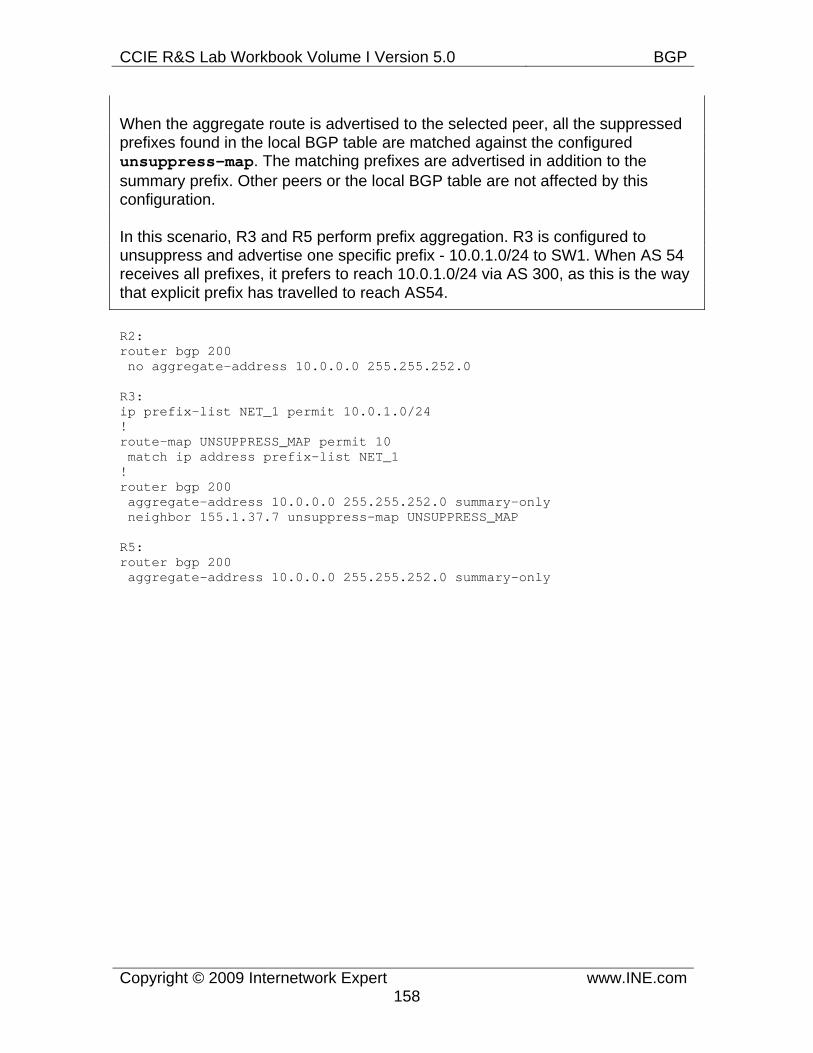
CCIE R&S Lab Workbook Volume I Version 5.0 BGP
Copyright © 2009 Internetwork Expert www.INE.com158
When the aggregate route is advertised to the selected peer, all the suppressed prefixes found in the local BGP table are matched against the configured unsuppress-map. The matching prefixes are advertised in addition to the summary prefix. Other peers or the local BGP table are not affected by this configuration.
In this scenario, R3 and R5 perform prefix aggregation. R3 is configured to unsuppress and advertise one specific prefix - 10.0.1.0/24 to SW1. When AS 54 receives all prefixes, it prefers to reach 10.0.1.0/24 via AS 300, as this is the way that explicit prefix has travelled to reach AS54.
R2: router bgp 200 no aggregate-address 10.0.0.0 255.255.252.0
R3: ip prefix-list NET_1 permit 10.0.1.0/24 ! route-map UNSUPPRESS_MAP permit 10 match ip address prefix-list NET_1 ! router bgp 200 aggregate-address 10.0.0.0 255.255.252.0 summary-only neighbor 155.1.37.7 unsuppress-map UNSUPPRESS_MAP R5: router bgp 200 aggregate-address 10.0.0.0 255.255.252.0 summary-only
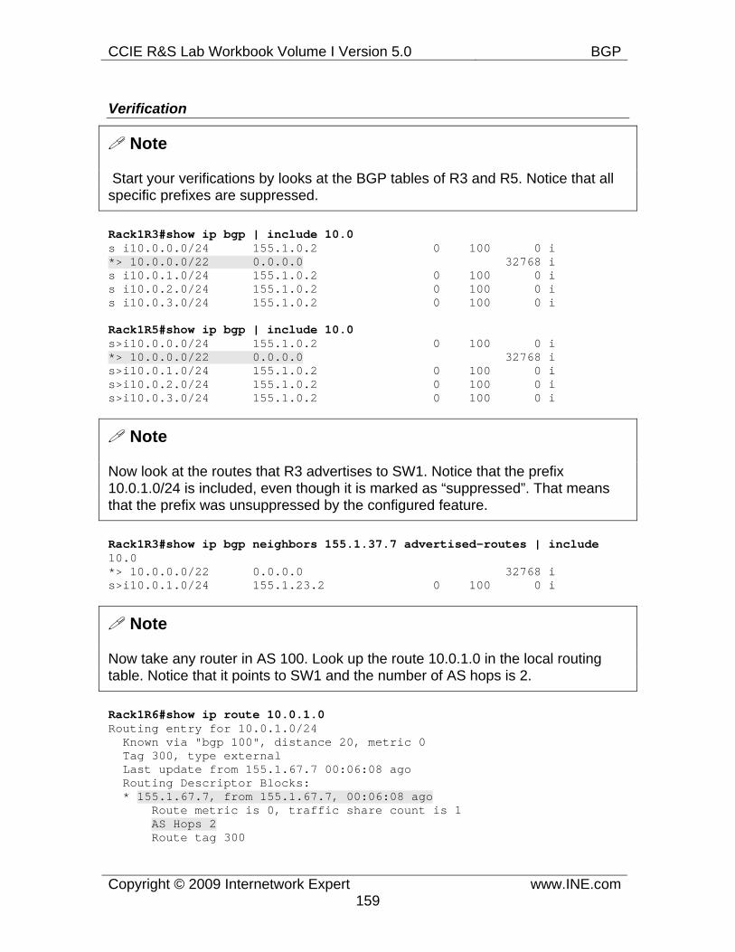
CCIE R&S Lab Workbook Volume I Version 5.0 BGP
Copyright © 2009 Internetwork Expert www.INE.com159
Verification
Note
Start your verifications by looks at the BGP tables of R3 and R5. Notice that all specific prefixes are suppressed.
Rack1R3#show ip bgp | include 10.0 s i10.0.0.0/24 155.1.0.2 0 100 0 i *> 10.0.0.0/22 0.0.0.0 32768 i s i10.0.1.0/24 155.1.0.2 0 100 0 i s i10.0.2.0/24 155.1.0.2 0 100 0 i s i10.0.3.0/24 155.1.0.2 0 100 0 i
Rack1R5#show ip bgp | include 10.0 s>i10.0.0.0/24 155.1.0.2 0 100 0 i *> 10.0.0.0/22 0.0.0.0 32768 i s>i10.0.1.0/24 155.1.0.2 0 100 0 i s>i10.0.2.0/24 155.1.0.2 0 100 0 i s>i10.0.3.0/24 155.1.0.2 0 100 0 i
Note
Now look at the routes that R3 advertises to SW1. Notice that the prefix 10.0.1.0/24 is included, even though it is marked as “suppressed”. That means that the prefix was unsuppressed by the configured feature.
Rack1R3#show ip bgp neighbors 155.1.37.7 advertised-routes | include 10.0 *> 10.0.0.0/22 0.0.0.0 32768 i s>i10.0.1.0/24 155.1.23.2 0 100 0 i
Note
Now take any router in AS 100. Look up the route 10.0.1.0 in the local routing table. Notice that it points to SW1 and the number of AS hops is 2.
Rack1R6#show ip route 10.0.1.0 Routing entry for 10.0.1.0/24 Known via "bgp 100", distance 20, metric 0 Tag 300, type external Last update from 155.1.67.7 00:06:08 ago Routing Descriptor Blocks: * 155.1.67.7, from 155.1.67.7, 00:06:08 ago Route metric is 0, traffic share count is 1 AS Hops 2 Route tag 300
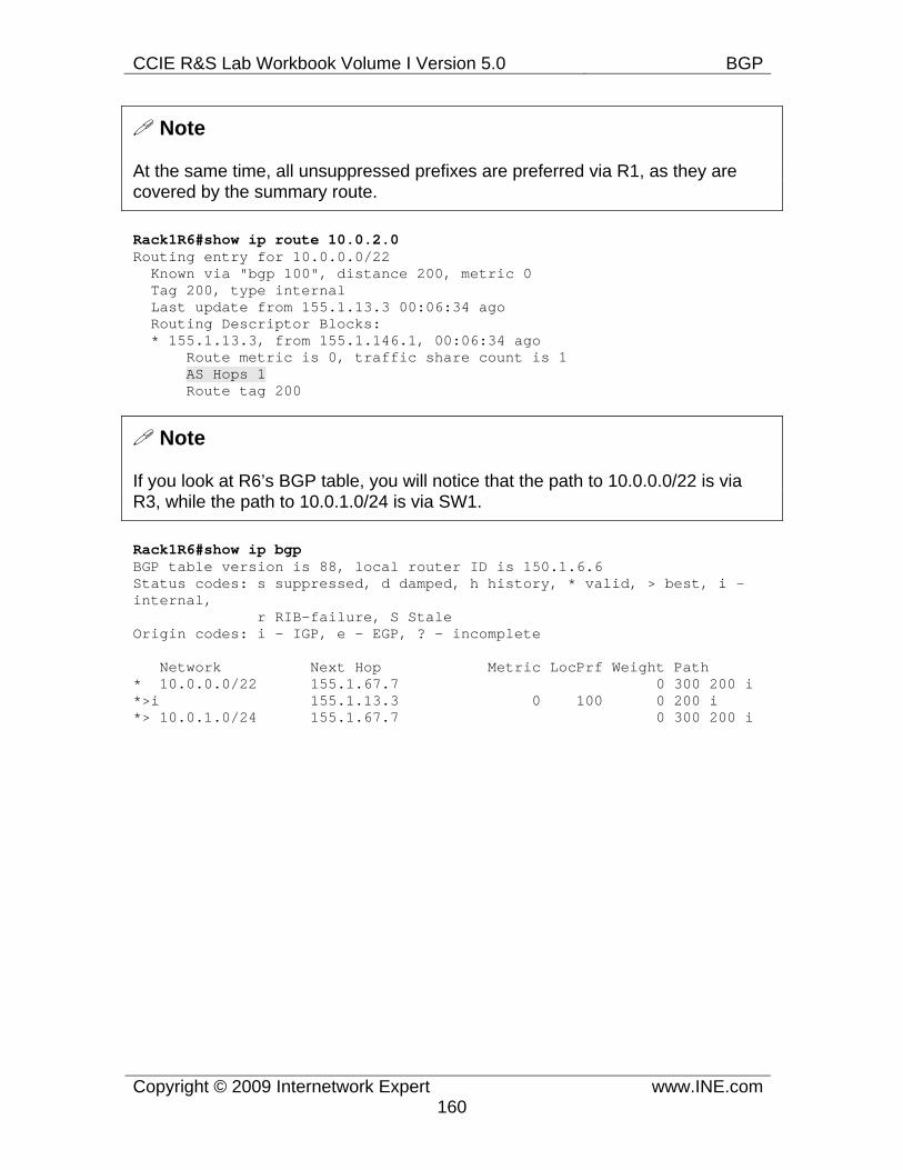
CCIE R&S Lab Workbook Volume I Version 5.0 BGP
Copyright © 2009 Internetwork Expert www.INE.com160
Note
At the same time, all unsuppressed prefixes are preferred via R1, as they are covered by the summary route.
Rack1R6#show ip route 10.0.2.0 Routing entry for 10.0.0.0/22 Known via "bgp 100", distance 200, metric 0 Tag 200, type internal Last update from 155.1.13.3 00:06:34 ago Routing Descriptor Blocks: * 155.1.13.3, from 155.1.146.1, 00:06:34 ago Route metric is 0, traffic share count is 1 AS Hops 1 Route tag 200
Note
If you look at R6’s BGP table, you will notice that the path to 10.0.0.0/22 is via R3, while the path to 10.0.1.0/24 is via SW1.
Rack1R6#show ip bgp BGP table version is 88, local router ID is 150.1.6.6 Status codes: s suppressed, d damped, h history, * valid, > best, i - internal, r RIB-failure, S Stale Origin codes: i - IGP, e - EGP, ? - incomplete
Network Next Hop Metric LocPrf Weight Path * 10.0.0.0/22 155.1.67.7 0 300 200 i *>i 155.1.13.3 0 100 0 200 i *> 10.0.1.0/24 155.1.67.7 0 300 200 i
CCIE R&S Lab Workbook Volume I Version 5.0 BGP
Copyright © 2009 Internetwork Expert www.INE.com161
7.34 BGP Aggregation - AS-Set • Configure R1 to aggregate the subnets 112.0.0.0/24-119.0.0.0/24 into one
prefix using the optimal prefix length. • Ensure that the new summary prefix is not accepted by AS 54 peers. • Do not use any filtering technique to accomplish this.
Configuration
Note
It is important to remember that aggregation hides information previous found in the specific prefixes. This includes all attributes, such as NEXT_HOP, AS_PATH and so on. The new prefix appears to be originated from within the local AS. This causes no problems if all specific prefixes belong to the local AS. However, when you summarize prefixes learned from other ASes, information hiding may result in the following dangerous consequences:
1) Suboptimal routing, due to the loss of path information, such as AS_PATH, MED and so on. 2) Routing loops, as removal of AS_PATH attribute and replacement it with an empty list will prevent BGP loop-detection mechanism from working properly.
The second issue is most dangerous. In order to overcome it, it is possible to insert a special new member into the AS_PATH of the newly created summary prefix. This element is called AS_SET and contains the AS numbers found in all AS_PATHs of the specific prefixes. This list of AS numbers is unordered, unlike the regular AS_SEQUENCE element. It’s only use is for routing loop prevention – when BGP receives a prefix it scans the AS_PATH attribute. If the local AS number is found in any of the AS_SET or AS_SEQUENCE elements, the prefix is dropped.
By default, the aggregated address in BGP will not include the AS-Set information. In order to force the use of this information, specify the as-set option as follows: aggregate-address <subnet> <mask> as-set.
In our scenario, AS100 speaker aggregates the prefixes learned from another ASes. If not the as-set feature, both BB1 and BB3 would have accepted the new summary prefix. If that would have happened, that in case when BB1 or BB3 lose route to say prefix 113.0.0.0 they would route to AS100 for this prefix, while AS 100 never had it. The solution aggregates the prefixes using the following bitmap breakdown:
1110|000.00000000.00000000.00000000
CCIE R&S Lab Workbook Volume I Version 5.0 BGP
Copyright © 2009 Internetwork Expert www.INE.com162
1110|001.00000000.00000000.00000000 ... 1110|111.00000000.00000000.00000000
Which results in the summary prefix of 112.0.0.0/5 or the same as 112.0.0.0 248.0.0.0
R1: router bgp 100 aggregate-address 112.0.0.0 248.0.0.0 summary-only as-set
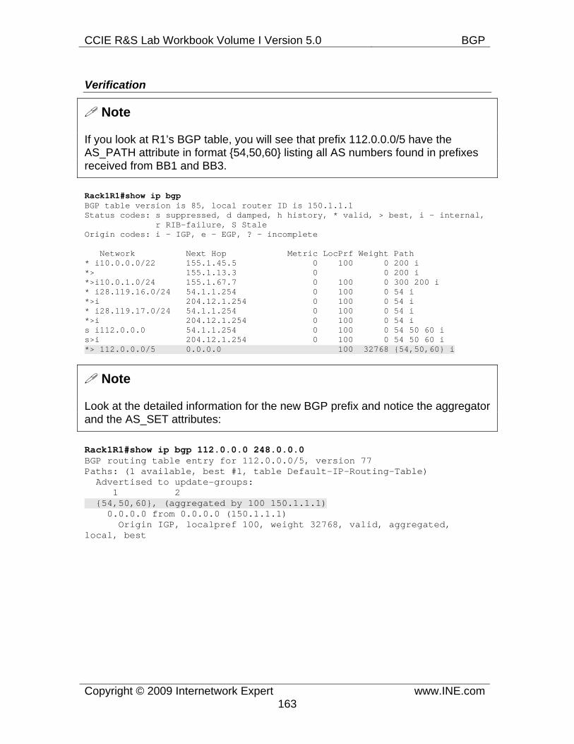
CCIE R&S Lab Workbook Volume I Version 5.0 BGP
Copyright © 2009 Internetwork Expert www.INE.com163
Verification
Note
If you look at R1’s BGP table, you will see that prefix 112.0.0.0/5 have the AS_PATH attribute in format {54,50,60} listing all AS numbers found in prefixes received from BB1 and BB3.
Rack1R1#show ip bgp BGP table version is 85, local router ID is 150.1.1.1 Status codes: s suppressed, d damped, h history, * valid, > best, i - internal, r RIB-failure, S Stale Origin codes: i - IGP, e - EGP, ? - incomplete
Network Next Hop Metric LocPrf Weight Path * i10.0.0.0/22 155.1.45.5 0 100 0 200 i *> 155.1.13.3 0 0 200 i *>i10.0.1.0/24 155.1.67.7 0 100 0 300 200 i * i28.119.16.0/24 54.1.1.254 0 100 0 54 i *>i 204.12.1.254 0 100 0 54 i * i28.119.17.0/24 54.1.1.254 0 100 0 54 i *>i 204.12.1.254 0 100 0 54 i s i112.0.0.0 54.1.1.254 0 100 0 54 50 60 i s>i 204.12.1.254 0 100 0 54 50 60 i *> 112.0.0.0/5 0.0.0.0 100 32768 {54,50,60} i
Note
Look at the detailed information for the new BGP prefix and notice the aggregator and the AS_SET attributes:
Rack1R1#show ip bgp 112.0.0.0 248.0.0.0 BGP routing table entry for 112.0.0.0/5, version 77 Paths: (1 available, best #1, table Default-IP-Routing-Table) Advertised to update-groups: 1 2 {54,50,60}, (aggregated by 100 150.1.1.1) 0.0.0.0 from 0.0.0.0 (150.1.1.1) Origin IGP, localpref 100, weight 32768, valid, aggregated, local, best
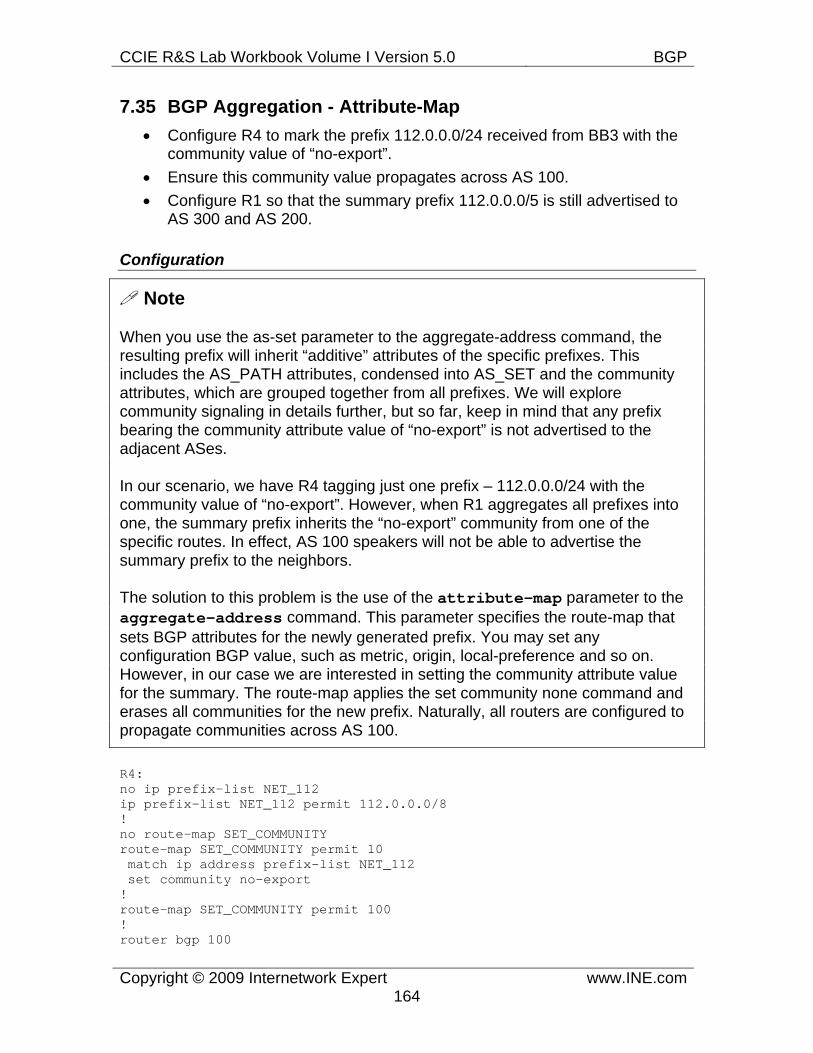
CCIE R&S Lab Workbook Volume I Version 5.0 BGP
Copyright © 2009 Internetwork Expert www.INE.com164
7.35 BGP Aggregation - Attribute-Map • Configure R4 to mark the prefix 112.0.0.0/24 received from BB3 with the
community value of “no-export”. • Ensure this community value propagates across AS 100. • Configure R1 so that the summary prefix 112.0.0.0/5 is still advertised to
AS 300 and AS 200.
Configuration
Note
When you use the as-set parameter to the aggregate-address command, the resulting prefix will inherit “additive” attributes of the specific prefixes. This includes the AS_PATH attributes, condensed into AS_SET and the community attributes, which are grouped together from all prefixes. We will explore community signaling in details further, but so far, keep in mind that any prefix bearing the community attribute value of “no-export” is not advertised to the adjacent ASes.
In our scenario, we have R4 tagging just one prefix – 112.0.0.0/24 with the community value of “no-export”. However, when R1 aggregates all prefixes into one, the summary prefix inherits the “no-export” community from one of the specific routes. In effect, AS 100 speakers will not be able to advertise the summary prefix to the neighbors.
The solution to this problem is the use of the attribute-map parameter to the aggregate-address command. This parameter specifies the route-map that sets BGP attributes for the newly generated prefix. You may set any configuration BGP value, such as metric, origin, local-preference and so on. However, in our case we are interested in setting the community attribute value for the summary. The route-map applies the set community none command and erases all communities for the new prefix. Naturally, all routers are configured to propagate communities across AS 100.
R4: no ip prefix-list NET_112 ip prefix-list NET_112 permit 112.0.0.0/8 ! no route-map SET_COMMUNITY route-map SET_COMMUNITY permit 10 match ip address prefix-list NET_112 set community no-export ! route-map SET_COMMUNITY permit 100 ! router bgp 100
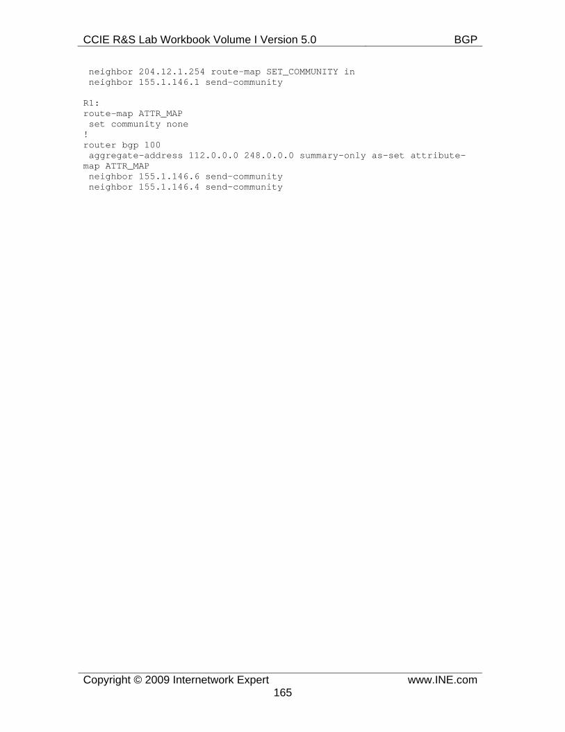
CCIE R&S Lab Workbook Volume I Version 5.0 BGP
Copyright © 2009 Internetwork Expert www.INE.com165
neighbor 204.12.1.254 route-map SET_COMMUNITY in neighbor 155.1.146.1 send-community
R1: route-map ATTR_MAP set community none ! router bgp 100 aggregate-address 112.0.0.0 248.0.0.0 summary-only as-set attribute-map ATTR_MAP neighbor 155.1.146.6 send-community neighbor 155.1.146.4 send-community
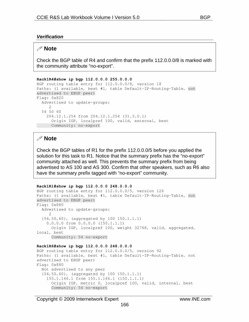
CCIE R&S Lab Workbook Volume I Version 5.0 BGP
Copyright © 2009 Internetwork Expert www.INE.com166
Verification
Note
Check the BGP table of R4 and confirm that the prefix 112.0.0.0/8 is marked with the community attribute “no-export”.
Rack1R4#show ip bgp 112.0.0.0 255.0.0.0 BGP routing table entry for 112.0.0.0/8, version 18 Paths: (1 available, best #1, table Default-IP-Routing-Table, not advertised to EBGP peer) Flag: 0x820 Advertised to update-groups: 2 54 50 60 204.12.1.254 from 204.12.1.254 (31.3.0.1) Origin IGP, localpref 100, valid, external, best Community: no-export
Note
Check the BGP tables of R1 for the prefix 112.0.0.0/5 before you applied the solution for this task to R1. Notice that the summary prefix has the “no-export” community attached as well. This prevents the summary prefix from being advertised to AS 100 and AS 300. Confirm that other speakers, such as R6 also have the summary prefix tagged with “no-export” community.
Rack1R1#show ip bgp 112.0.0.0 248.0.0.0 BGP routing table entry for 112.0.0.0/5, version 126 Paths: (1 available, best #1, table Default-IP-Routing-Table, not advertised to EBGP peer) Flag: 0x880 Advertised to update-groups: 2 {54,50,60}, (aggregated by 100 150.1.1.1) 0.0.0.0 from 0.0.0.0 (150.1.1.1) Origin IGP, localpref 100, weight 32768, valid, aggregated, local, best Community: 54 no-export
Rack1R6#show ip bgp 112.0.0.0 248.0.0.0 BGP routing table entry for 112.0.0.0/5, version 92 Paths: (1 available, best #1, table Default-IP-Routing-Table, not advertised to EBGP peer) Flag: 0x880 Not advertised to any peer {54,50,60}, (aggregated by 100 150.1.1.1) 155.1.146.1 from 155.1.146.1 (150.1.1.1) Origin IGP, metric 0, localpref 100, valid, internal, best Community: 54 no-export

CCIE R&S Lab Workbook Volume I Version 5.0 BGP
Copyright © 2009 Internetwork Expert www.INE.com167
Note
Now apply the solution to R1 and check the BGP table entry for 112.0.0.0/5 again. Confirm that the summary prefix does not have any community values now, and R1 advertises it to any eBGP peer.
Rack1R1#show ip bgp 112.0.0.0 248.0.0.0 BGP routing table entry for 112.0.0.0/5, version 127 Paths: (1 available, best #1, table Default-IP-Routing-Table) Flag: 0x880 Advertised to update-groups: 1 2 3 {54,50,60}, (aggregated by 100 150.1.1.1) 0.0.0.0 from 0.0.0.0 (150.1.1.1) Origin IGP, localpref 100, weight 32768, valid, aggregated, local, best
Rack1R1#show ip bgp neighbors 155.1.13.3 advertised-routes BGP table version is 127, local router ID is 150.1.1.1 Status codes: s suppressed, d damped, h history, * valid, > best, i - internal, r RIB-failure, S Stale Origin codes: i - IGP, e - EGP, ? - incomplete
Network Next Hop Metric LocPrf Weight Path *>i10.0.1.0/24 155.1.67.7 0 100 0 300 200 i *>i28.119.16.0/24 204.12.1.254 0 100 0 54 i *>i28.119.17.0/24 204.12.1.254 0 100 0 54 i *> 112.0.0.0/5 0.0.0.0 100 32768 {54,50,60} i *>i155.1.0.0 155.1.146.4 0 100 0 i
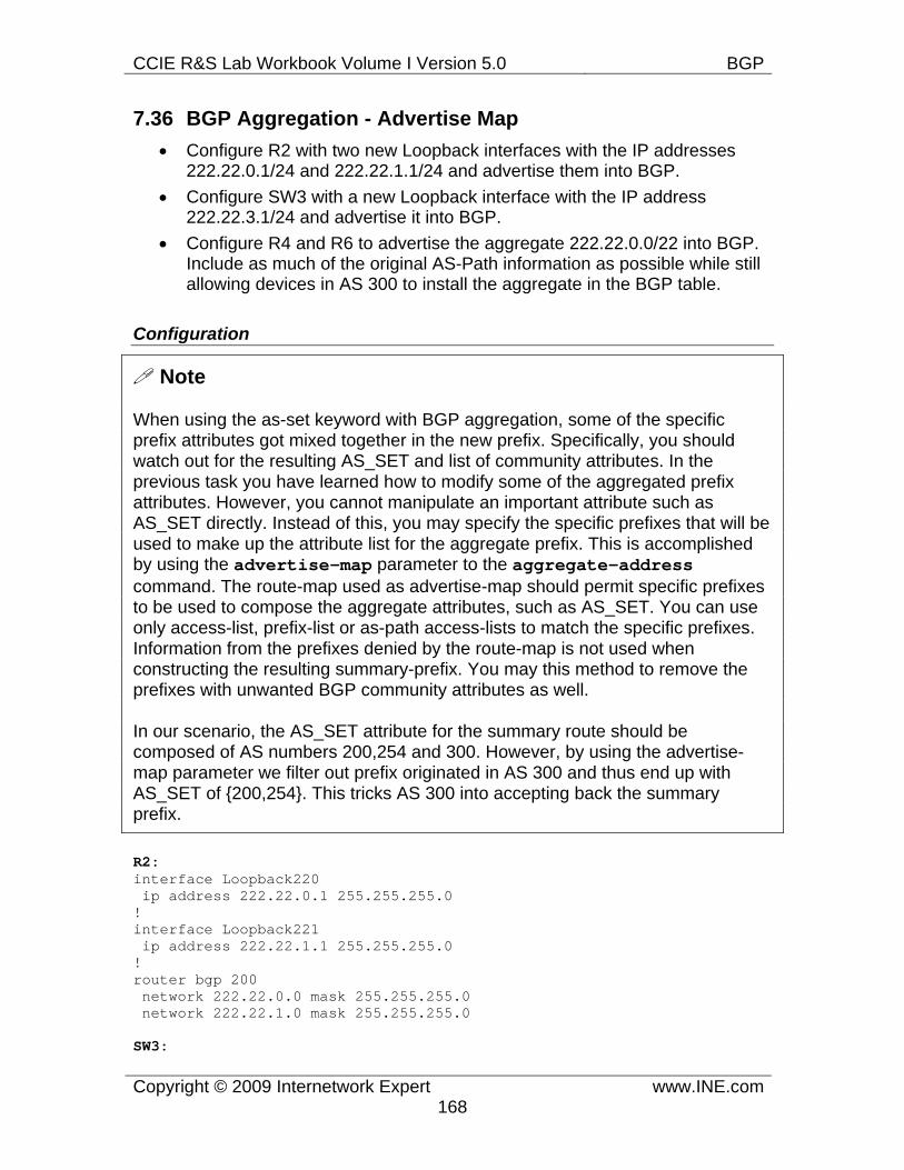
CCIE R&S Lab Workbook Volume I Version 5.0 BGP
Copyright © 2009 Internetwork Expert www.INE.com168
7.36 BGP Aggregation - Advertise Map • Configure R2 with two new Loopback interfaces with the IP addresses
222.22.0.1/24 and 222.22.1.1/24 and advertise them into BGP. • Configure SW3 with a new Loopback interface with the IP address
222.22.3.1/24 and advertise it into BGP. • Configure R4 and R6 to advertise the aggregate 222.22.0.0/22 into BGP.
Include as much of the original AS-Path information as possible while still allowing devices in AS 300 to install the aggregate in the BGP table.
Configuration
Note
When using the as-set keyword with BGP aggregation, some of the specific prefix attributes got mixed together in the new prefix. Specifically, you should watch out for the resulting AS_SET and list of community attributes. In the previous task you have learned how to modify some of the aggregated prefix attributes. However, you cannot manipulate an important attribute such as AS_SET directly. Instead of this, you may specify the specific prefixes that will be used to make up the attribute list for the aggregate prefix. This is accomplished by using the advertise-map parameter to the aggregate-address command. The route-map used as advertise-map should permit specific prefixes to be used to compose the aggregate attributes, such as AS_SET. You can use only access-list, prefix-list or as-path access-lists to match the specific prefixes. Information from the prefixes denied by the route-map is not used when constructing the resulting summary-prefix. You may this method to remove the prefixes with unwanted BGP community attributes as well.
In our scenario, the AS_SET attribute for the summary route should be composed of AS numbers 200,254 and 300. However, by using the advertise-map parameter we filter out prefix originated in AS 300 and thus end up with AS_SET of {200,254}. This tricks AS 300 into accepting back the summary prefix.
R2: interface Loopback220 ip address 222.22.0.1 255.255.255.0 ! interface Loopback221 ip address 222.22.1.1 255.255.255.0 ! router bgp 200 network 222.22.0.0 mask 255.255.255.0 network 222.22.1.0 mask 255.255.255.0
SW3:
CCIE R&S Lab Workbook Volume I Version 5.0 BGP
Copyright © 2009 Internetwork Expert www.INE.com169
interface Loopback 223 ip address 222.22.3.1 255.255.255.0 ! router bgp 300 network 222.22.3.0 mask 255.255.255.0
R4, R6: ip prefix-list AS300_PREFIX permit 222.22.3.0/24 ! route-map ADVERTISE_MAP deny 10 match ip address prefix-list AS300_PREFIX ! route-map ADVERTISE_MAP permit 100 ! router bgp 100 aggregate-address 222.22.0.0 255.255.252.0 summary-only as-set advertise-map ADVERTISE_MAP
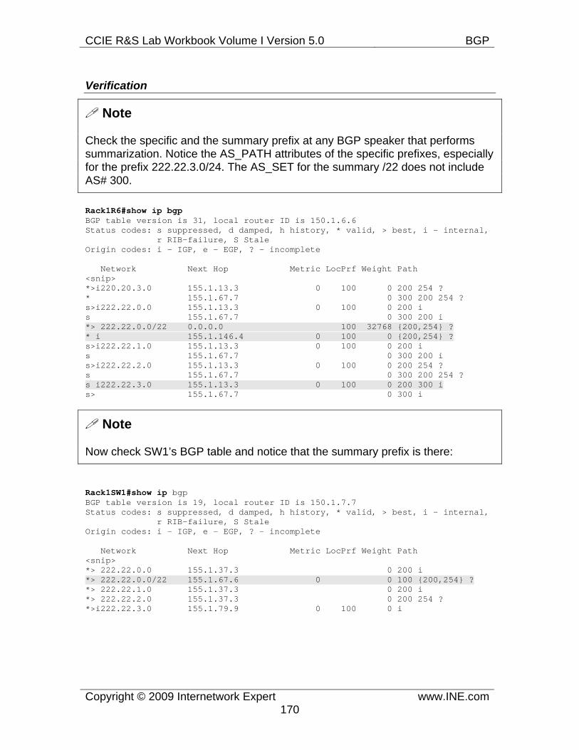
CCIE R&S Lab Workbook Volume I Version 5.0 BGP
Copyright © 2009 Internetwork Expert www.INE.com170
Verification
Note
Check the specific and the summary prefix at any BGP speaker that performs summarization. Notice the AS_PATH attributes of the specific prefixes, especially for the prefix 222.22.3.0/24. The AS_SET for the summary /22 does not include AS# 300.
Rack1R6#show ip bgp BGP table version is 31, local router ID is 150.1.6.6 Status codes: s suppressed, d damped, h history, * valid, > best, i - internal, r RIB-failure, S Stale Origin codes: i - IGP, e - EGP, ? - incomplete
Network Next Hop Metric LocPrf Weight Path <snip> *>i220.20.3.0 155.1.13.3 0 100 0 200 254 ? * 155.1.67.7 0 300 200 254 ? s>i222.22.0.0 155.1.13.3 0 100 0 200 i s 155.1.67.7 0 300 200 i *> 222.22.0.0/22 0.0.0.0 100 32768 {200,254} ? * i 155.1.146.4 0 100 0 {200,254} ? s>i222.22.1.0 155.1.13.3 0 100 0 200 i s 155.1.67.7 0 300 200 i s>i222.22.2.0 155.1.13.3 0 100 0 200 254 ? s 155.1.67.7 0 300 200 254 ? s i222.22.3.0 155.1.13.3 0 100 0 200 300 i s> 155.1.67.7 0 300 i
Note
Now check SW1’s BGP table and notice that the summary prefix is there:
Rack1SW1#show ip bgp BGP table version is 19, local router ID is 150.1.7.7 Status codes: s suppressed, d damped, h history, * valid, > best, i - internal, r RIB-failure, S Stale Origin codes: i - IGP, e - EGP, ? - incomplete
Network Next Hop Metric LocPrf Weight Path <snip> *> 222.22.0.0 155.1.37.3 0 200 i *> 222.22.0.0/22 155.1.67.6 0 0 100 {200,254} ? *> 222.22.1.0 155.1.37.3 0 200 i *> 222.22.2.0 155.1.37.3 0 200 254 ? *>i222.22.3.0 155.1.79.9 0 100 0 i
CCIE R&S Lab Workbook Volume I Version 5.0 BGP
Copyright © 2009 Internetwork Expert www.INE.com171
7.37 BGP Communities • Configure AS200 to set local-preference attribute to 200 for eBGP prefixes
tagged with community value 200:200 • Configure AS100 to signal AS200 to prefer path to the prefixes originated
in AS 60 via R3.
Configuration
Note
BGP Communities are optional transitive attributes used mainly to associate an administrative tag to a route. All prefixes with the same community essentially belong to the same group and share some property. Using communities allows for manipulation of BGP prefixes based on their “meaning” (e.g. customer prefixes, peer prefixes, upstream networks) not the network values. Even though BGP community attribute is transitive, Cisco IOS routers do not pass it across BGP sessions by default. In order to start sending the community values to a particular peer, you have to activate this feature using the command neighbor <IP> send-community.
There could be many communities associated with a BGP prefix and every community attribute has a 32 bit value. There are two formats to read a community value: raw, as a 32-bit number and structured, as a pair AS Number:16-bit value. The second format makes it easier to interpret communities, as they naturally points to the AS that originated the tagging. Notice that by default community values are displayed in 32-bit format, and to use the structured notation you need to enter the global configuration command ip bgp-community new-format. Since there are no ASes numbered 0 or 65535, the BGP community ranges 0x0000:0x0000-0x0000:0xFFFF and 0xFFFF:0x0000-0xFFFF:0xFFFF are reserved and not available for public use. There are three well-known BGP community values from reserved range: NO_EXPORT (0xFFFF:0xFF01), NO_ADVERTISE (0xFFFF:0xFF02) and NO_EXPORT_SUBCONFED (0xFFFF:0xFF03) interpreted by all BGP speakers. We will discuss their use in separate tasks.
Other community values do not trigger any special BGP processing unless you configure your BGP speaker to do so. The most common use of communities is to signal a neighboring AS (since the attribute is transitive) some special sort of treatment to apply to the tagged prefixes. For example, imagine a company with its own AS, being a customer of two ISPs in separate ASes. Every ISP may implement a policy, where routes tagged with a community value say AS#:101 are prepended with ISP’s AS# when advertised upstream. This allows the customer to instruct the ISPs for prepending of specific prefixes and thus adjusting BGP bestpath selection in the upstream AS. More advanced uses
CCIE R&S Lab Workbook Volume I Version 5.0 BGP
Copyright © 2009 Internetwork Expert www.INE.com172
include implementing community-based filtering, such as using communities to signal “advertise this prefix only to directly connected peers” or using communities to signal QoS policy. As you can see, communities could be used to implement almost any configurable policy. However, the use of community values should be agreed between two ASes, as semantic interpretation is left to the administrator.
In order to set a community value, use the route-map command set community <value1> <value2> ... <valueN> or set community additive <value1> <value2> ... <valueN>. The former command will impose a new set of community values on the prefix. The other command will add the specified communities to the list already attached to the path. In order to match a community value, you need to configure a community-list and use it in a route-map later. There are two types of lists: standard and expanded. A list could be either numbered (1-99 for standard, 100-500 for expanded) or named. Standard community list entries permit or deny a community value, such as following:
ip community-list 1 permit 100:10 100:20 ip community-list 1 deny no-export
In order for an entry to match, all mentioned community values must exist in the prefix. For example, the first line in the example above would match only prefixes with two community values: 100:10 and 100:20. Essentially, OR logic is implemented by setting multiple entries, and AND logic is implemented for values in a single line.
Expanded community lists allow the use of regular expressions for community matching. This is helpful when you need to match a range or community values. Before applying an expanded community-list, BGP engine will order the communities for every prefix numerically (since the communities are just 32 bit values) and remove the duplicates. This allows for deterministic construction of regular expressions. We will illustrate the use of most common wildcard characters:
^100:1_200:1 – match communities 100:1 and 200:1 in the beginning (^ anchor) of the community list. Here “_” means the “space” separating different community values. Notice that the prefix may not have any community values ranged between 100:1 and 200:1 due to the community ordering. Also, the prefix may not have any community less than 100:1 as this is the first community in the list.
300:2$ - match the community 300:2 at the end of the community list ($ anchor). The prefix may not have any community greater than 300:2 as this is the last value in the list.
CCIE R&S Lab Workbook Volume I Version 5.0 BGP
Copyright © 2009 Internetwork Expert www.INE.com173
400:[2-9]_ – match a range of communities ([] specify a rage) such as 300:1, 300:2,..., 300:9. The use of “_” at the end is important; otherwise this pattern would also match 300:22, 300:2333 and so on. This may be one of the most useful wildcard constructs for matching community ranges.
100:1.*_ - illustrates the use of two wildcard characters. The “.” matches any digit (you may also use [0-9] in this context) and “*” means “repeat the previous pattern zero or more times”. The pattern above would match 100:1, 100:2, 100:22, 100:11 and so on. You may use “+” instead of “*” which means “repeat one or more times”. Thus 100:1.+_ will not match against 100:1.
100:([0-9]2)+_ - demonstrates the use of “()” for grouping. Here “[0-9]2” is treated as a single group for the operator “+”. Thus the pattern would match 100:1212, 100:2222, 100:0202 and so on.
100:1_|100:2_ – here we use the alternation symbol “|”. The pattern would match either 100:1 or 100:2. You may use “|” with grouping such as 100:(12)|(22) that will match 100:12 or 100:22.
In spite of expanded community lists flexibility, most times you need just the standard lists, as the number of destination groups is usually limited. In our scenario, AS 200 advertises to its peers that the community 200:200 is treated as having local preference of 200 inside the AS. In order to implement this policy, we configure inbound route-maps on R3 and R5 matching the community 200:200 and setting the local-preference to 200. R1 matches the prefixes originated in AS 60 and mark them with the community value of 200:200 signaling the preferred path.
R1: no ip as-path access-list 1 ip as-path access-list 1 permit 60$ ! route-map SET_COMMUNITY permit 10 match as-path 1 set community 200:200 ! route-map SET_COMMUNITY permit 100
router bgp 100 neighbor 155.1.13.3 send-community neighbor 155.1.13.3 route-map SET_COMMUNITY out
R3: ip community-list standard 200:200 permit 200:200 ! route-map SET_LOCAL_PREFERENCE permit 10 match community 200:200 set local-preference 200
CCIE R&S Lab Workbook Volume I Version 5.0 BGP
Copyright © 2009 Internetwork Expert www.INE.com174
! route-map SET_LOCAL_PREFERENCE permit 100 ! router bgp 200 neighbor 155.1.13.1 route-map SET_LOCAL_PREFERENCE in
R5: ip community-list standard 200:200 permit 200:200 ! route-map SET_LOCAL_PREFERENCE permit 10 match community 200:200 set local-preference 200 ! route-map SET_LOCAL_PREFERENCE permit 100 ! router bgp 200 neighbor 155.1.45.4 route-map SET_LOCAL_PREFERENCE in
CCIE R&S Lab Workbook Volume I Version 5.0 BGP
Copyright © 2009 Internetwork Expert www.INE.com175
Verification
Note
Check the paths toward prefixes originated in AS 60 on R3. Notice the local preference of 200 associated with the path via R1.
Rack1R3#sh ip bgp regexp 60$ BGP table version is 21, local router ID is 150.1.3.3 Status codes: s suppressed, d damped, h history, * valid, > best, i - internal, r RIB-failure, S Stale Origin codes: i - IGP, e - EGP, ? - incomplete
Network Next Hop Metric LocPrf Weight Path * 112.0.0.0 155.1.37.7 0 300 100 54 50 60 i *> 155.1.13.1 200 0 100 54 50 60 i * 113.0.0.0 155.1.37.7 0 300 100 54 50 60 i *> 155.1.13.1 200 0 100 54 50 60 i
Note
Look at the BGP attributes for 113.0.0.0/8. Notice the local preference and the community value. The community is presented in unstructured format. Configure the router to display the communities in structured format:
Rack1R3#sh ip bgp 113.0.0.0 BGP routing table entry for 113.0.0.0/8, version 21 Paths: (2 available, best #2, table Default-IP-Routing-Table) Advertised to update-groups: 1 2 3 300 100 54 50 60 155.1.37.7 from 155.1.37.7 (150.1.7.7) Origin IGP, localpref 100, valid, external 100 54 50 60 155.1.13.1 from 155.1.13.1 (150.1.1.1) Origin IGP, localpref 200, valid, external, best Community: 13107400
Rack1R3#conf t Enter configuration commands, one per line. End with CNTL/Z. Rack1R3(config)#ip bgp-community new-format
Rack1R3#sh ip bgp 113.0.0.0 BGP routing table entry for 113.0.0.0/8, version 21 Paths: (2 available, best #2, table Default-IP-Routing-Table) Advertised to update-groups: 1 2 3 300 100 54 50 60 155.1.37.7 from 155.1.37.7 (150.1.7.7) Origin IGP, localpref 100, valid, external 100 54 50 60 155.1.13.1 from 155.1.13.1 (150.1.1.1)
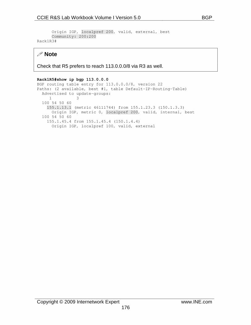
CCIE R&S Lab Workbook Volume I Version 5.0 BGP
Copyright © 2009 Internetwork Expert www.INE.com176
Origin IGP, localpref 200, valid, external, best Community: 200:200 Rack1R3#
Note
Check that R5 prefers to reach 113.0.0.0/8 via R3 as well.
Rack1R5#show ip bgp 113.0.0.0 BGP routing table entry for 113.0.0.0/8, version 22 Paths: (2 available, best #1, table Default-IP-Routing-Table) Advertised to update-groups: 1 3 100 54 50 60 155.1.13.1 (metric 46111744) from 155.1.23.3 (150.1.3.3) Origin IGP, metric 0, localpref 200, valid, internal, best 100 54 50 60 155.1.45.4 from 155.1.45.4 (150.1.4.4) Origin IGP, localpref 100, valid, external
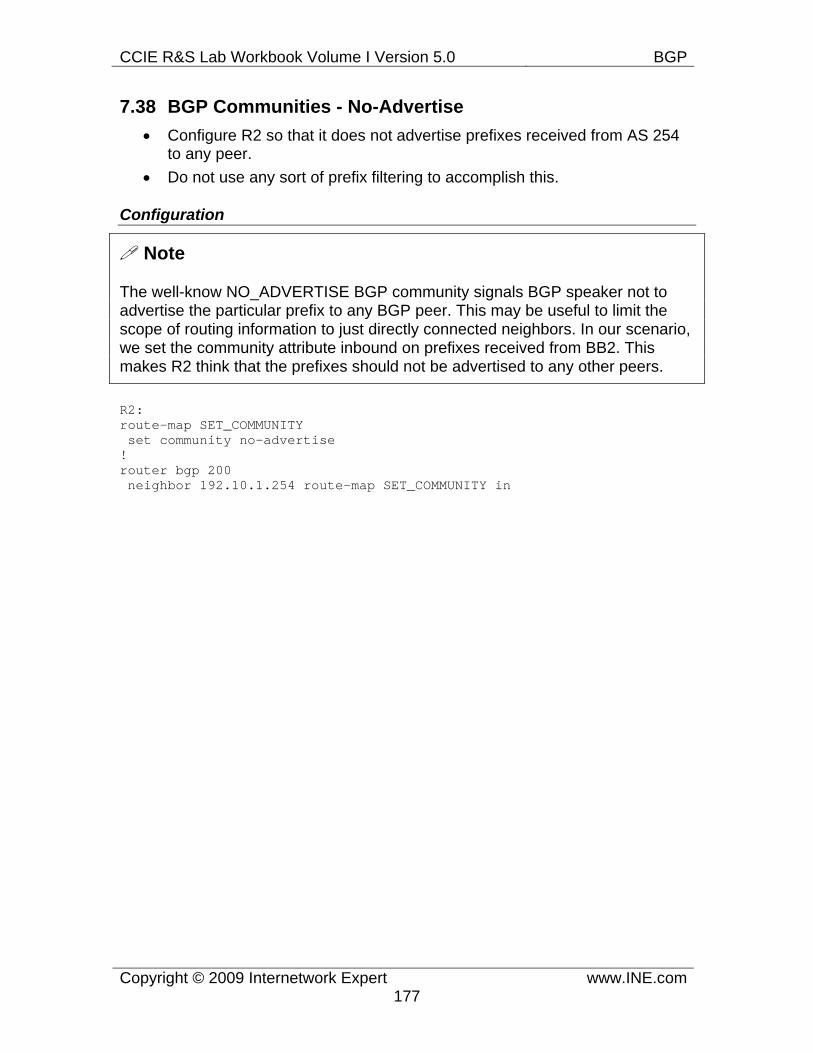
CCIE R&S Lab Workbook Volume I Version 5.0 BGP
Copyright © 2009 Internetwork Expert www.INE.com177
7.38 BGP Communities - No-Advertise • Configure R2 so that it does not advertise prefixes received from AS 254
to any peer. • Do not use any sort of prefix filtering to accomplish this.
Configuration
Note
The well-know NO_ADVERTISE BGP community signals BGP speaker not to advertise the particular prefix to any BGP peer. This may be useful to limit the scope of routing information to just directly connected neighbors. In our scenario, we set the community attribute inbound on prefixes received from BB2. This makes R2 think that the prefixes should not be advertised to any other peers.
R2: route-map SET_COMMUNITY set community no-advertise ! router bgp 200 neighbor 192.10.1.254 route-map SET_COMMUNITY in
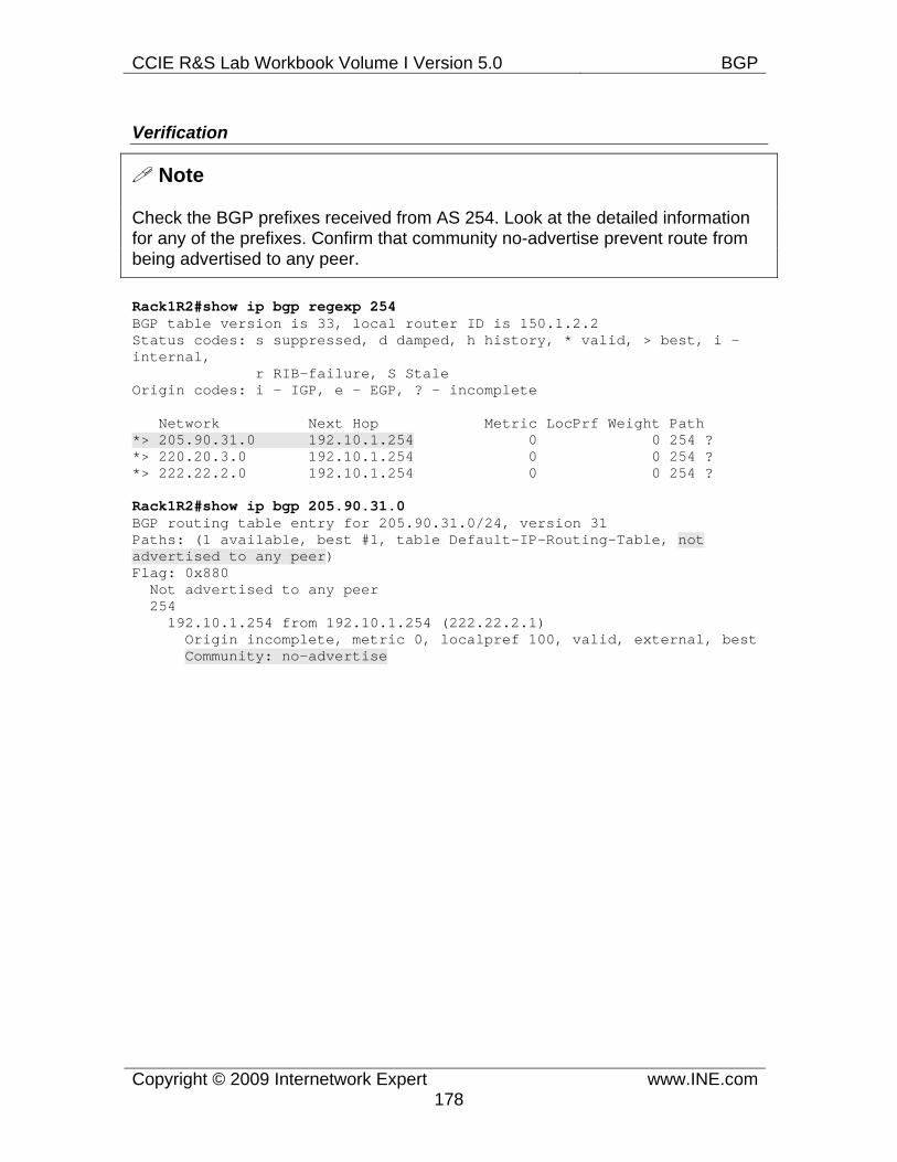
CCIE R&S Lab Workbook Volume I Version 5.0 BGP
Copyright © 2009 Internetwork Expert www.INE.com178
Verification
Note
Check the BGP prefixes received from AS 254. Look at the detailed information for any of the prefixes. Confirm that community no-advertise prevent route from being advertised to any peer.
Rack1R2#show ip bgp regexp 254 BGP table version is 33, local router ID is 150.1.2.2 Status codes: s suppressed, d damped, h history, * valid, > best, i - internal, r RIB-failure, S Stale Origin codes: i - IGP, e - EGP, ? - incomplete
Network Next Hop Metric LocPrf Weight Path *> 205.90.31.0 192.10.1.254 0 0 254 ? *> 220.20.3.0 192.10.1.254 0 0 254 ? *> 222.22.2.0 192.10.1.254 0 0 254 ?
Rack1R2#show ip bgp 205.90.31.0 BGP routing table entry for 205.90.31.0/24, version 31 Paths: (1 available, best #1, table Default-IP-Routing-Table, not advertised to any peer) Flag: 0x880 Not advertised to any peer 254 192.10.1.254 from 192.10.1.254 (222.22.2.1) Origin incomplete, metric 0, localpref 100, valid, external, best Community: no-advertise
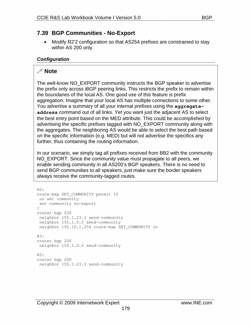
CCIE R&S Lab Workbook Volume I Version 5.0 BGP
Copyright © 2009 Internetwork Expert www.INE.com179
7.39 BGP Communities - No-Export • Modify R2’2 configuration so that AS254 prefixes are constrained to stay
within AS 200 only.
Configuration
Note
The well-know NO_EXPORT community instructs the BGP speaker to advertise the prefix only across iBGP peering links. This restricts the prefix to remain within the boundaries of the local AS. One good use of this feature is prefix aggregation. Imagine that your local AS has multiple connections to some other. You advertise a summary of all your internal prefixes using the aggregate-address command out of all links. Yet you want just the adjacent AS to select the best entry point based on the MED attribute. This could be accomplished by advertising the specific prefixes tagged with NO_EXPORT community along with the aggregates. The neighboring AS would be able to select the best path based on the specific information (e.g. MED) but will not advertise the specifics any further, thus containing the routing information.
In our scenario, we simply tag all prefixes received from BB2 with the community NO_EXPORT. Since the community value must propagate to all peers, we enable sending community in all AS200’s BGP speakers. There is no need to send BGP communities to all speakers, just make sure the border speakers always receive the community-tagged routes.
R2: route-map SET_COMMUNITY permit 10 no set community set community no-export ! router bgp 200 neighbor 155.1.23.3 send-community neighbor 155.1.0.5 send-community neighbor 192.10.1.254 route-map SET_COMMUNITY in
R3: router bgp 200 neighbor 155.1.0.5 send-community
R5: router bgp 200 neighbor 155.1.23.3 send-community
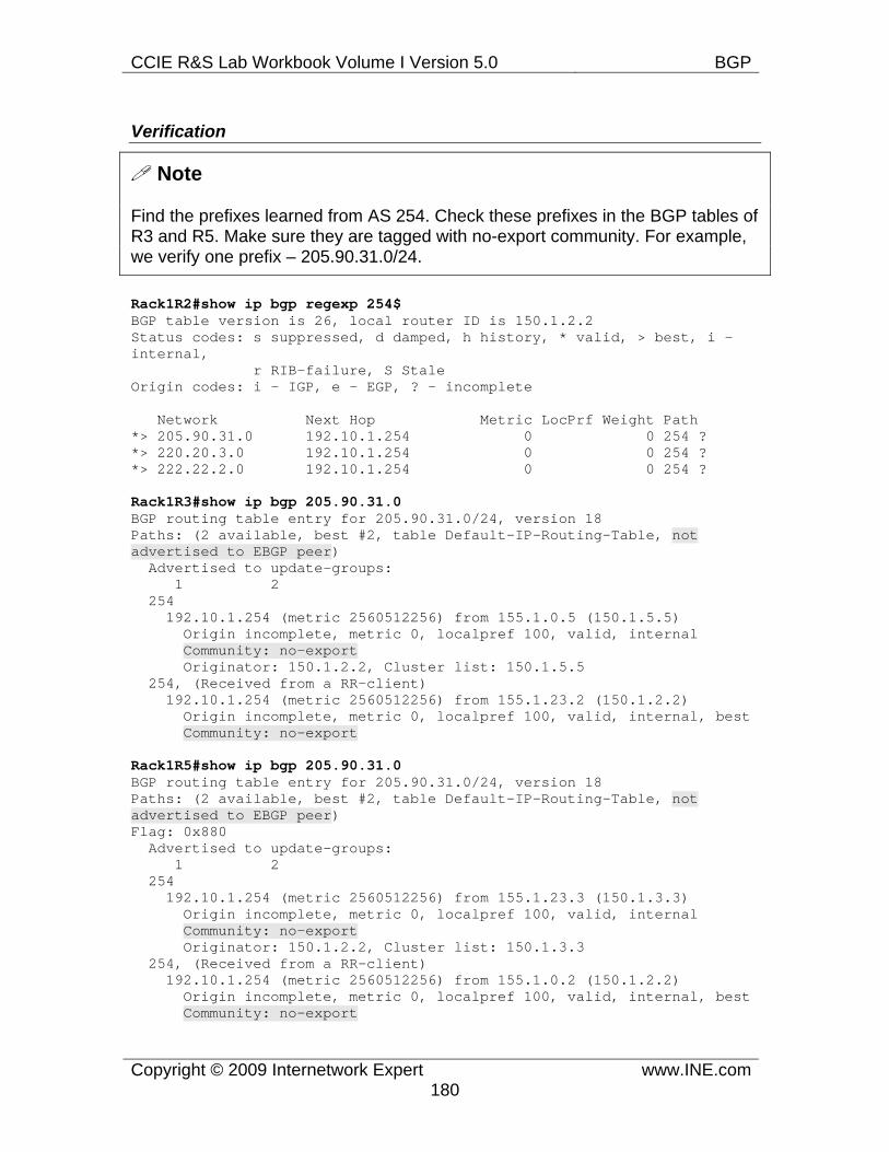
CCIE R&S Lab Workbook Volume I Version 5.0 BGP
Copyright © 2009 Internetwork Expert www.INE.com180
Verification
Note
Find the prefixes learned from AS 254. Check these prefixes in the BGP tables of R3 and R5. Make sure they are tagged with no-export community. For example, we verify one prefix – 205.90.31.0/24.
Rack1R2#show ip bgp regexp 254$ BGP table version is 26, local router ID is 150.1.2.2 Status codes: s suppressed, d damped, h history, * valid, > best, i - internal, r RIB-failure, S Stale Origin codes: i - IGP, e - EGP, ? - incomplete
Network Next Hop Metric LocPrf Weight Path *> 205.90.31.0 192.10.1.254 0 0 254 ? *> 220.20.3.0 192.10.1.254 0 0 254 ? *> 222.22.2.0 192.10.1.254 0 0 254 ?
Rack1R3#show ip bgp 205.90.31.0 BGP routing table entry for 205.90.31.0/24, version 18 Paths: (2 available, best #2, table Default-IP-Routing-Table, not advertised to EBGP peer) Advertised to update-groups: 1 2 254 192.10.1.254 (metric 2560512256) from 155.1.0.5 (150.1.5.5) Origin incomplete, metric 0, localpref 100, valid, internal Community: no-export Originator: 150.1.2.2, Cluster list: 150.1.5.5 254, (Received from a RR-client) 192.10.1.254 (metric 2560512256) from 155.1.23.2 (150.1.2.2) Origin incomplete, metric 0, localpref 100, valid, internal, best Community: no-export
Rack1R5#show ip bgp 205.90.31.0 BGP routing table entry for 205.90.31.0/24, version 18 Paths: (2 available, best #2, table Default-IP-Routing-Table, not advertised to EBGP peer) Flag: 0x880 Advertised to update-groups: 1 2 254 192.10.1.254 (metric 2560512256) from 155.1.23.3 (150.1.3.3) Origin incomplete, metric 0, localpref 100, valid, internal Community: no-export Originator: 150.1.2.2, Cluster list: 150.1.3.3 254, (Received from a RR-client) 192.10.1.254 (metric 2560512256) from 155.1.0.2 (150.1.2.2) Origin incomplete, metric 0, localpref 100, valid, internal, best Community: no-export
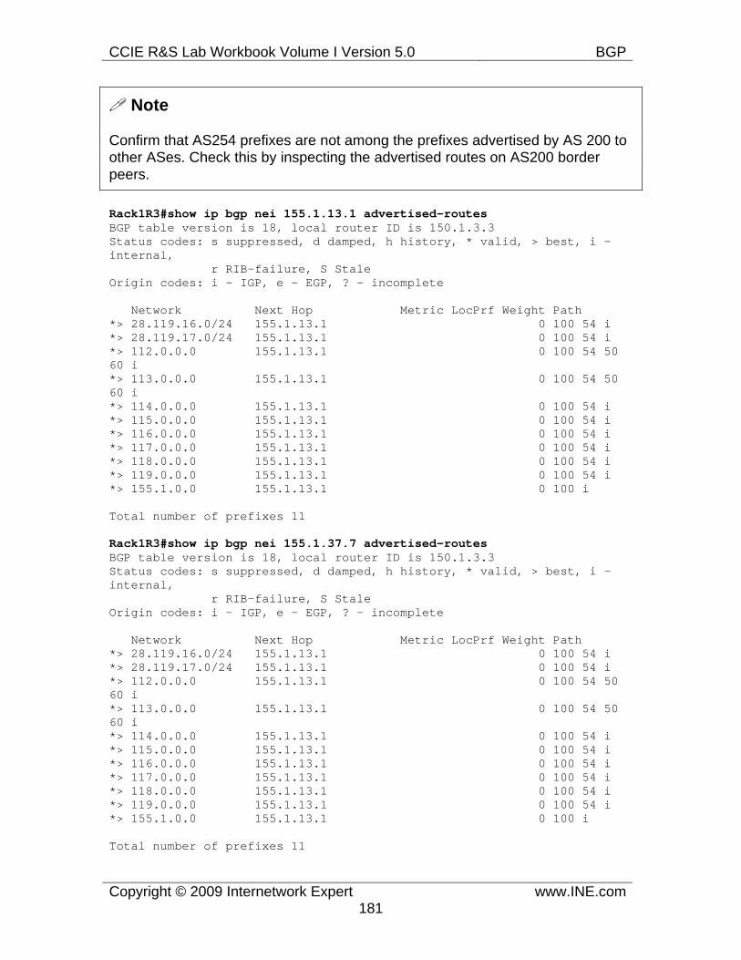
CCIE R&S Lab Workbook Volume I Version 5.0 BGP
Copyright © 2009 Internetwork Expert www.INE.com181
Note
Confirm that AS254 prefixes are not among the prefixes advertised by AS 200 to other ASes. Check this by inspecting the advertised routes on AS200 border peers.
Rack1R3#show ip bgp nei 155.1.13.1 advertised-routes BGP table version is 18, local router ID is 150.1.3.3 Status codes: s suppressed, d damped, h history, * valid, > best, i - internal, r RIB-failure, S Stale Origin codes: i - IGP, e - EGP, ? - incomplete
Network Next Hop Metric LocPrf Weight Path *> 28.119.16.0/24 155.1.13.1 0 100 54 i *> 28.119.17.0/24 155.1.13.1 0 100 54 i *> 112.0.0.0 155.1.13.1 0 100 54 50 60 i *> 113.0.0.0 155.1.13.1 0 100 54 50 60 i *> 114.0.0.0 155.1.13.1 0 100 54 i *> 115.0.0.0 155.1.13.1 0 100 54 i *> 116.0.0.0 155.1.13.1 0 100 54 i *> 117.0.0.0 155.1.13.1 0 100 54 i *> 118.0.0.0 155.1.13.1 0 100 54 i *> 119.0.0.0 155.1.13.1 0 100 54 i *> 155.1.0.0 155.1.13.1 0 100 i
Total number of prefixes 11
Rack1R3#show ip bgp nei 155.1.37.7 advertised-routes BGP table version is 18, local router ID is 150.1.3.3 Status codes: s suppressed, d damped, h history, * valid, > best, i - internal, r RIB-failure, S Stale Origin codes: i - IGP, e - EGP, ? - incomplete
Network Next Hop Metric LocPrf Weight Path *> 28.119.16.0/24 155.1.13.1 0 100 54 i *> 28.119.17.0/24 155.1.13.1 0 100 54 i *> 112.0.0.0 155.1.13.1 0 100 54 50 60 i *> 113.0.0.0 155.1.13.1 0 100 54 50 60 i *> 114.0.0.0 155.1.13.1 0 100 54 i *> 115.0.0.0 155.1.13.1 0 100 54 i *> 116.0.0.0 155.1.13.1 0 100 54 i *> 117.0.0.0 155.1.13.1 0 100 54 i *> 118.0.0.0 155.1.13.1 0 100 54 i *> 119.0.0.0 155.1.13.1 0 100 54 i *> 155.1.0.0 155.1.13.1 0 100 i
Total number of prefixes 11
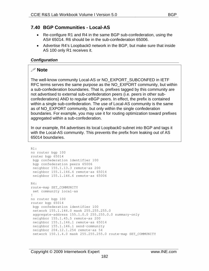
CCIE R&S Lab Workbook Volume I Version 5.0 BGP
Copyright © 2009 Internetwork Expert www.INE.com182
7.40 BGP Communities - Local-AS • Re-configure R1 and R4 in the same BGP sub-confederation, using the
AS# 65014. R6 should be in the sub-confederation 65006. • Advertise R4’s Loopback0 network in the BGP, but make sure that inside
AS 100 only R1 receives it.
Configuration
Note
The well-know community Local-AS or NO_EXPORT_SUBCONFED in IETF RFC terms serves the same purpose as the NO_EXPORT community, but within a sub-confederation boundaries. That is, prefixes tagged by this community are not advertised to external sub-confederation peers (i.e. peers in other sub-confederations) AND to regular eBGP peers. In effect, the prefix is contained within a single sub-confederation. The use of Local-AS community is the same as of NO_EXPORT community, but only within the single confederation boundaries. For example, you may use it for routing optimization toward prefixes aggregated within a sub-confederation.
In our example, R4 advertises its local Loopback0 subnet into BGP and tags it with the Local-AS community. This prevents the prefix from leaking out of AS 65014 boundaries.
R1: no router bgp 100 router bgp 65014 bgp confederation identifier 100 bgp confederation peers 65006 neighbor 155.1.13.3 remote-as 200 neighbor 155.1.146.4 remote-as 65014 neighbor 155.1.146.6 remote-as 65006
R4: route-map SET_COMMUNITY set community local-as ! no router bgp 100 router bgp 65014 bgp confederation identifier 100 network 155.1.146.0 mask 255.255.255.0 aggregate-address 155.1.0.0 255.255.0.0 summary-only neighbor 155.1.45.5 remote-as 200 neighbor 155.1.146.1 remote-as 65014 neighbor 155.1.146.1 send-community neighbor 204.12.1.254 remote-as 54 network 150.1.4.0 mask 255.255.255.0 route-map SET_COMMUNITY
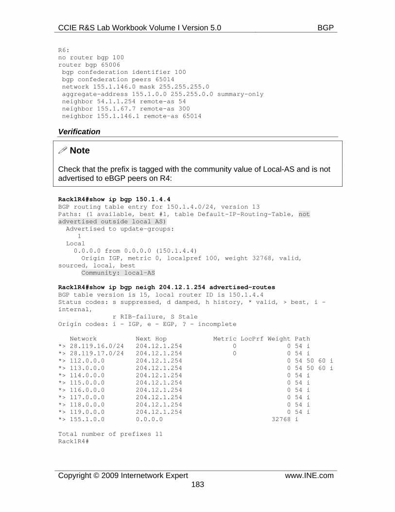
CCIE R&S Lab Workbook Volume I Version 5.0 BGP
Copyright © 2009 Internetwork Expert www.INE.com183
R6: no router bgp 100 router bgp 65006 bgp confederation identifier 100 bgp confederation peers 65014 network 155.1.146.0 mask 255.255.255.0 aggregate-address 155.1.0.0 255.255.0.0 summary-only neighbor 54.1.1.254 remote-as 54 neighbor 155.1.67.7 remote-as 300 neighbor 155.1.146.1 remote-as 65014
Verification
Note
Check that the prefix is tagged with the community value of Local-AS and is not advertised to eBGP peers on R4:
Rack1R4#show ip bgp 150.1.4.4 BGP routing table entry for 150.1.4.0/24, version 13 Paths: (1 available, best #1, table Default-IP-Routing-Table, not advertised outside local AS) Advertised to update-groups: 1 Local 0.0.0.0 from 0.0.0.0 (150.1.4.4) Origin IGP, metric 0, localpref 100, weight 32768, valid, sourced, local, best Community: local-AS
Rack1R4#show ip bgp neigh 204.12.1.254 advertised-routes BGP table version is 15, local router ID is 150.1.4.4 Status codes: s suppressed, d damped, h history, * valid, > best, i - internal, r RIB-failure, S Stale Origin codes: i - IGP, e - EGP, ? - incomplete
Network Next Hop Metric LocPrf Weight Path *> 28.119.16.0/24 204.12.1.254 0 0 54 i *> 28.119.17.0/24 204.12.1.254 0 0 54 i *> 112.0.0.0 204.12.1.254 0 54 50 60 i *> 113.0.0.0 204.12.1.254 0 54 50 60 i *> 114.0.0.0 204.12.1.254 0 54 i *> 115.0.0.0 204.12.1.254 0 54 i *> 116.0.0.0 204.12.1.254 0 54 i *> 117.0.0.0 204.12.1.254 0 54 i *> 118.0.0.0 204.12.1.254 0 54 i *> 119.0.0.0 204.12.1.254 0 54 i *> 155.1.0.0 0.0.0.0 32768 i
Total number of prefixes 11 Rack1R4#
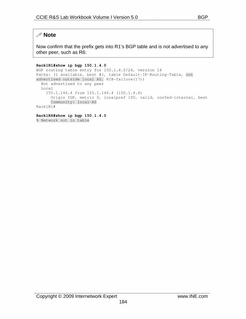
CCIE R&S Lab Workbook Volume I Version 5.0 BGP
Copyright © 2009 Internetwork Expert www.INE.com184
Note
Now confirm that the prefix gets into R1’s BGP table and is not advertised to any other peer, such as R6:
Rack1R1#show ip bgp 150.1.4.0 BGP routing table entry for 150.1.4.0/24, version 14 Paths: (1 available, best #1, table Default-IP-Routing-Table, not advertised outside local AS, RIB-failure(17)) Not advertised to any peer Local 155.1.146.4 from 155.1.146.4 (150.1.4.4) Origin IGP, metric 0, localpref 100, valid, confed-internal, best Community: local-AS Rack1R1#
Rack1R6#show ip bgp 150.1.4.0 % Network not in table
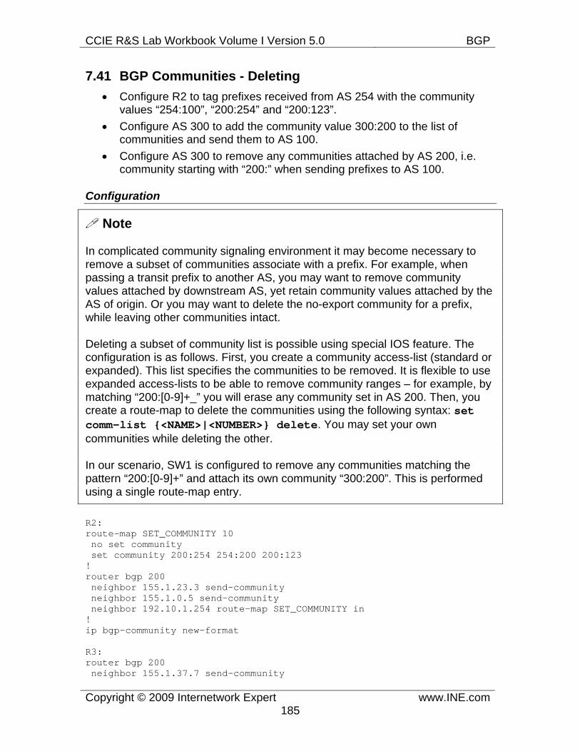
CCIE R&S Lab Workbook Volume I Version 5.0 BGP
Copyright © 2009 Internetwork Expert www.INE.com185
7.41 BGP Communities - Deleting • Configure R2 to tag prefixes received from AS 254 with the community
values “254:100”, “200:254” and “200:123”. • Configure AS 300 to add the community value 300:200 to the list of
communities and send them to AS 100. • Configure AS 300 to remove any communities attached by AS 200, i.e.
community starting with “200:” when sending prefixes to AS 100.
Configuration
Note
In complicated community signaling environment it may become necessary to remove a subset of communities associate with a prefix. For example, when passing a transit prefix to another AS, you may want to remove community values attached by downstream AS, yet retain community values attached by the AS of origin. Or you may want to delete the no-export community for a prefix, while leaving other communities intact.
Deleting a subset of community list is possible using special IOS feature. The configuration is as follows. First, you create a community access-list (standard or expanded). This list specifies the communities to be removed. It is flexible to use expanded access-lists to be able to remove community ranges – for example, by matching “200:[0-9]+_” you will erase any community set in AS 200. Then, you create a route-map to delete the communities using the following syntax: set comm-list {<NAME>|<NUMBER>} delete. You may set your own communities while deleting the other.
In our scenario, SW1 is configured to remove any communities matching the pattern “200:[0-9]+” and attach its own community “300:200”. This is performed using a single route-map entry.
R2: route-map SET_COMMUNITY 10 no set community set community 200:254 254:200 200:123 ! router bgp 200 neighbor 155.1.23.3 send-community neighbor 155.1.0.5 send-community neighbor 192.10.1.254 route-map SET_COMMUNITY in ! ip bgp-community new-format
R3: router bgp 200 neighbor 155.1.37.7 send-community
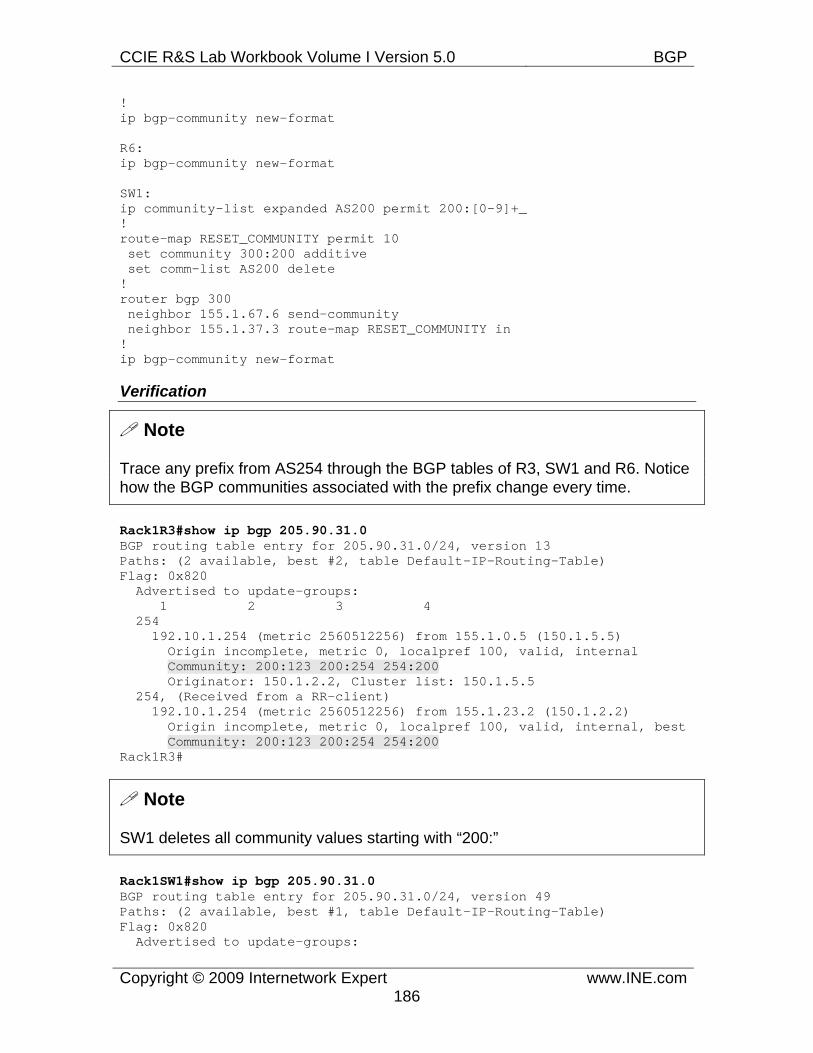
CCIE R&S Lab Workbook Volume I Version 5.0 BGP
Copyright © 2009 Internetwork Expert www.INE.com186
! ip bgp-community new-format
R6: ip bgp-community new-format
SW1: ip community-list expanded AS200 permit 200:[0-9]+_ ! route-map RESET_COMMUNITY permit 10 set community 300:200 additive set comm-list AS200 delete ! router bgp 300 neighbor 155.1.67.6 send-community neighbor 155.1.37.3 route-map RESET_COMMUNITY in ! ip bgp-community new-format
Verification
Note
Trace any prefix from AS254 through the BGP tables of R3, SW1 and R6. Notice how the BGP communities associated with the prefix change every time.
Rack1R3#show ip bgp 205.90.31.0 BGP routing table entry for 205.90.31.0/24, version 13 Paths: (2 available, best #2, table Default-IP-Routing-Table) Flag: 0x820 Advertised to update-groups: 1 2 3 4 254 192.10.1.254 (metric 2560512256) from 155.1.0.5 (150.1.5.5) Origin incomplete, metric 0, localpref 100, valid, internal Community: 200:123 200:254 254:200 Originator: 150.1.2.2, Cluster list: 150.1.5.5 254, (Received from a RR-client) 192.10.1.254 (metric 2560512256) from 155.1.23.2 (150.1.2.2) Origin incomplete, metric 0, localpref 100, valid, internal, best Community: 200:123 200:254 254:200 Rack1R3#
Note
SW1 deletes all community values starting with “200:”
Rack1SW1#show ip bgp 205.90.31.0 BGP routing table entry for 205.90.31.0/24, version 49 Paths: (2 available, best #1, table Default-IP-Routing-Table) Flag: 0x820 Advertised to update-groups:
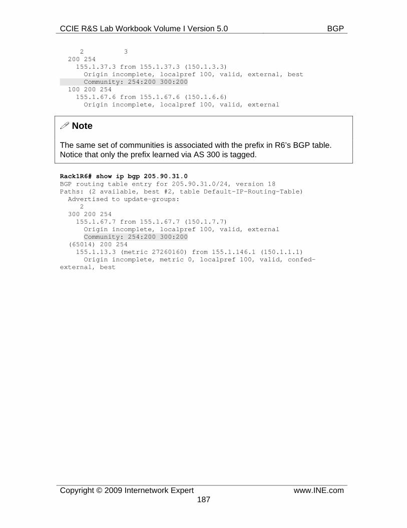
CCIE R&S Lab Workbook Volume I Version 5.0 BGP
Copyright © 2009 Internetwork Expert www.INE.com187
2 3 200 254 155.1.37.3 from 155.1.37.3 (150.1.3.3) Origin incomplete, localpref 100, valid, external, best Community: 254:200 300:200 100 200 254 155.1.67.6 from 155.1.67.6 (150.1.6.6) Origin incomplete, localpref 100, valid, external
Note
The same set of communities is associated with the prefix in R6’s BGP table. Notice that only the prefix learned via AS 300 is tagged.
Rack1R6# show ip bgp 205.90.31.0 BGP routing table entry for 205.90.31.0/24, version 18 Paths: (2 available, best #2, table Default-IP-Routing-Table) Advertised to update-groups: 2 300 200 254 155.1.67.7 from 155.1.67.7 (150.1.7.7) Origin incomplete, localpref 100, valid, external Community: 254:200 300:200 (65014) 200 254 155.1.13.3 (metric 27260160) from 155.1.146.1 (150.1.1.1) Origin incomplete, metric 0, localpref 100, valid, confed-external, best
CCIE R&S Lab Workbook Volume I Version 5.0 BGP
Copyright © 2009 Internetwork Expert www.INE.com188
7.42 BGP Conditional Advertisement • Configure R3 in such a way that AS 300 uses AS 100 to get to all prefixes
learned from AS 254. • If the link between R1 and R3 goes down traffic from AS 300 to AS 254
should be rerouted directly to AS 200.
Configuration
Note
Conditional advertisement allows BGP speaker to advertise a set of BGP prefixes to a peer only if certain other prefixes are present or not present in the local BGP table. Thus, the existence (or non-existence) of those “trigger” prefixes is used as a condition to advertise selected prefixes to a peer. Conditional advertisements are helpful in situations with multiple uplinks to different ASes. For example, assume that your AS is connected to a pair of ISPs. One ISP charges you more, and thus you only want to use it in case of emergency with the primary ISP. Based on this, you want to advertise your local prefixes to the “expensive” ISP only in case if the primary fails. In order to detect the primary ISP failure, you track a certain prefix learned from the primary ISP. This allows for more sophisticated tracking of the connectivity issue, compared to simply tracking the interface state. Once the tracked prefix is gone, all local prefixes are announced to the “expensive” ISP, until the moment the tracked prefix appears again.
The syntax for conditional advertisement is as follows:
neighbor <IP> advertise-map MAP1 {non-exist|exist-map} MAP2
The configuration involves defining two route-maps. One route-map (MAP1) selects the prefixes to be advertised to the peer. These prefixes must already exist in the local BGP table. The other route-map (MAP2) selects the prefixes to be tracked in the local BGP table. If this is a “non-exist” map, than condition is triggered when no prefixes in the BGP table match the route-map. If this is an “exist” map, then condition is triggered when there is a prefix in the BGP table matching the route-map. BGP process performs condition verification every time BGP scanner runs (60 seconds by default) so it may take some time after your configuration change before the conditional advertisement occurs.
In our scenario we advertise the link connecting R1 and R3 into BGP. We then create a route-map matching this prefix. This route-map is used as a “non-exist” condition for the advertisement of AS 254 prefixes. The prefixes are selected using an AS_PATH access-list matching the regular expression “254$”
CCIE R&S Lab Workbook Volume I Version 5.0 BGP
Copyright © 2009 Internetwork Expert www.INE.com189
R3: ip as-path access-list 1 permit 254$ ! route-map ADVERTISE_MAP permit 10 match as-path 1 ! ip prefix-list LINK_R1_R3 permit 155.1.13.0/24 ! route-map NON_EXIST_MAP permit 10 match ip address prefix-list LINK_R1_R3 ! router bgp 200 network 155.1.13.0 mask 255.255.255.0 neighbor 155.1.37.7 advertise-map ADVERTISE_MAP non-exist-map NON_EXIST_MAP
CCIE R&S Lab Workbook Volume I Version 5.0 BGP
Copyright © 2009 Internetwork Expert www.INE.com190
Verification
Note
First, we check the “normal” conditions: the link between R1 and R3 is up. The prefix is in R3’s BGP table.
Rack1R3#show ip bgp 155.1.13.0 BGP routing table entry for 155.1.13.0/24, version 3 Paths: (1 available, best #1, table Default-IP-Routing-Table) Advertised to update-groups: 1 2 3 4 Local 0.0.0.0 from 0.0.0.0 (150.1.3.3) Origin IGP, metric 0, localpref 100, weight 32768, valid, sourced, local, best
Note
AS 254 prefixes are not advertised to SW1, even though they are in the local BGP table.
Rack1R3#show ip bgp regexp 254$ BGP table version is 33, local router ID is 150.1.3.3 Status codes: s suppressed, d damped, h history, * valid, > best, i - internal, r RIB-failure, S Stale Origin codes: i - IGP, e - EGP, ? - incomplete
Network Next Hop Metric LocPrf Weight Path * i205.90.31.0 192.10.1.254 0 100 0 254 ? *>i 192.10.1.254 0 100 0 254 ? * i220.20.3.0 192.10.1.254 0 100 0 254 ? *>i 192.10.1.254 0 100 0 254 ? * i222.22.2.0 192.10.1.254 0 100 0 254 ? *>i 192.10.1.254 0 100 0 254 ?
CCIE R&S Lab Workbook Volume I Version 5.0 BGP
Copyright © 2009 Internetwork Expert www.INE.com191
Rack1R3#show ip bgp neighbors 155.1.37.7 advertised-routes BGP table version is 16, local router ID is 150.1.3.3 Status codes: s suppressed, d damped, h history, * valid, > best, i - internal, r RIB-failure, S Stale Origin codes: i - IGP, e - EGP, ? - incomplete
Network Next Hop Metric LocPrf Weight Path *> 28.119.16.0/24 155.1.13.1 0 100 54 i *> 28.119.17.0/24 155.1.13.1 0 100 54 i *> 112.0.0.0 155.1.13.1 0 100 54 50 60 i *> 113.0.0.0 155.1.13.1 0 100 54 50 60 i *> 114.0.0.0 155.1.13.1 0 100 54 i *> 115.0.0.0 155.1.13.1 0 100 54 i *> 116.0.0.0 155.1.13.1 0 100 54 i *> 117.0.0.0 155.1.13.1 0 100 54 i *> 118.0.0.0 155.1.13.1 0 100 54 i *> 119.0.0.0 155.1.13.1 0 100 54 i *> 155.1.0.0 155.1.13.1 0 100 i *> 155.1.13.0/24 0.0.0.0 0 32768 i
Total number of prefixes 12
Note
Check the state of the advertise map associated with SW1. Notice that status is “Withdraw” meaning that prefixes matching the advertise-map are not advertised to SW1.
Rack1R3#show ip bgp neighbors 155.1.37.7 BGP neighbor is 155.1.37.7, remote AS 300, external link <snip> Condition-map NON_EXIST_MAP, Advertise-map ADVERTISE_MAP, status: Withdraw <snip>
Note
Now shutdown the link connecting R1 and R3 and check the prefixes advertised to SW1. Notice that AS254 prefixes are now advertised.
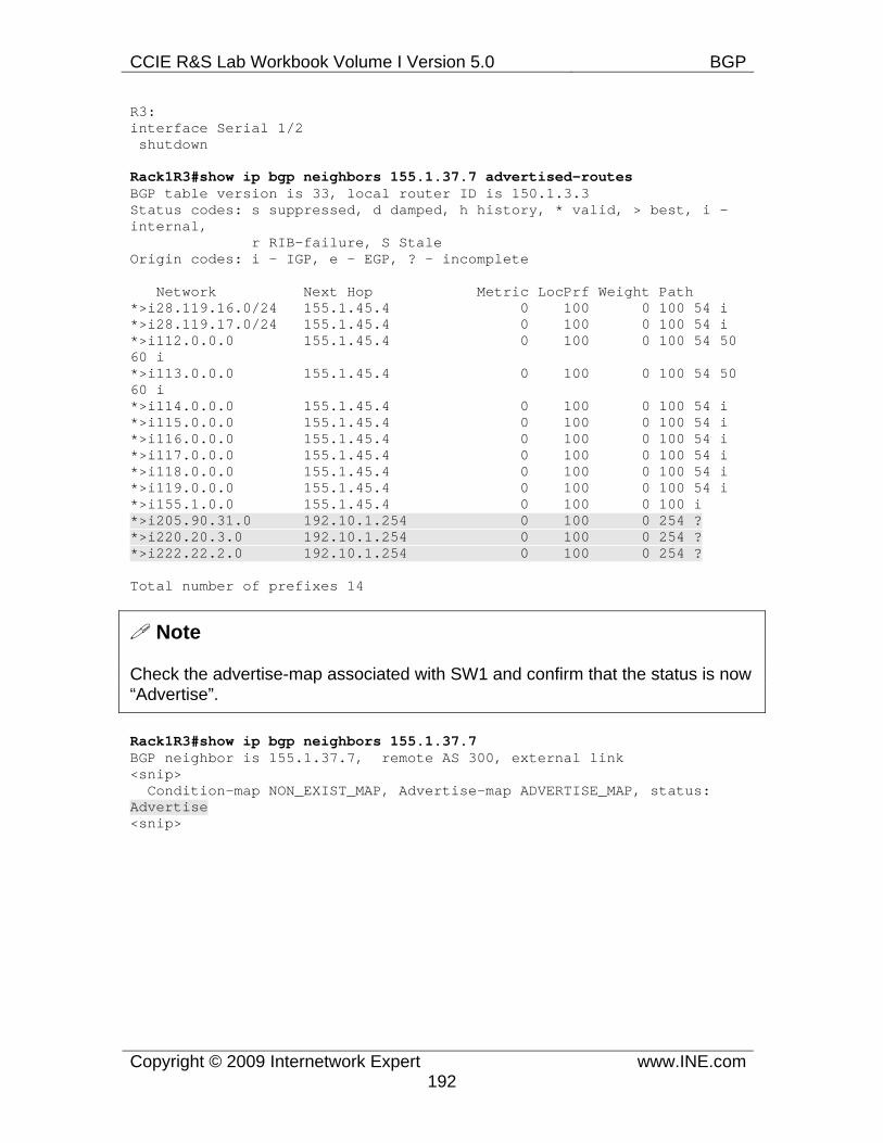
CCIE R&S Lab Workbook Volume I Version 5.0 BGP
Copyright © 2009 Internetwork Expert www.INE.com192
R3: interface Serial 1/2 shutdown
Rack1R3#show ip bgp neighbors 155.1.37.7 advertised-routes BGP table version is 33, local router ID is 150.1.3.3 Status codes: s suppressed, d damped, h history, * valid, > best, i - internal, r RIB-failure, S Stale Origin codes: i - IGP, e - EGP, ? - incomplete
Network Next Hop Metric LocPrf Weight Path *>i28.119.16.0/24 155.1.45.4 0 100 0 100 54 i *>i28.119.17.0/24 155.1.45.4 0 100 0 100 54 i *>i112.0.0.0 155.1.45.4 0 100 0 100 54 50 60 i *>i113.0.0.0 155.1.45.4 0 100 0 100 54 50 60 i *>i114.0.0.0 155.1.45.4 0 100 0 100 54 i *>i115.0.0.0 155.1.45.4 0 100 0 100 54 i *>i116.0.0.0 155.1.45.4 0 100 0 100 54 i *>i117.0.0.0 155.1.45.4 0 100 0 100 54 i *>i118.0.0.0 155.1.45.4 0 100 0 100 54 i *>i119.0.0.0 155.1.45.4 0 100 0 100 54 i *>i155.1.0.0 155.1.45.4 0 100 0 100 i *>i205.90.31.0 192.10.1.254 0 100 0 254 ? *>i220.20.3.0 192.10.1.254 0 100 0 254 ? *>i222.22.2.0 192.10.1.254 0 100 0 254 ?
Total number of prefixes 14
Note
Check the advertise-map associated with SW1 and confirm that the status is now “Advertise”.
Rack1R3#show ip bgp neighbors 155.1.37.7 BGP neighbor is 155.1.37.7, remote AS 300, external link <snip> Condition-map NON_EXIST_MAP, Advertise-map ADVERTISE_MAP, status: Advertise <snip>
CCIE R&S Lab Workbook Volume I Version 5.0 BGP
Copyright © 2009 Internetwork Expert www.INE.com193
7.43 BGP Conditional Route Injection • Configure R2 with four new Loopback interfaces with the IP addresses
10.0.0.1/24, 10.0.1.1/24, 10.0.2.1/24 & 10.0.3.1/24 and advertise them into BGP.
• Configure R2 to originate an aggregate route for these networks that does not overlap any address space. Ensure no other devices in the BGP network see the individual subnet routes of this aggregate.
• Configure BGP Conditional Route Injection on R4 and R6 in such a way that traffic from AS 54 going to the subnet 10.0.1.0/24 enters via R4, while traffic to the subnet 10.0.2.0/24 enters via R6.
Configuration
Note
Conditional Route Injection (CRI) is special feature that allows a BGP speaker to “de-aggregate” a particular prefix. As you know, aggregation is critical to large-scale routing in order to reduce routing table size and increase stability. CRI operation is opposite to aggregation, and its purpose is to create specific prefixes at administrator’s discretion. This may be useful to optimize routing by advertising some specific subnets of the aggregate across a certain path. CRI is similar to BGP unsuppress-map feature, but it will work on any router, not just the one originating the aggregate prefix. However, due to the lack of information about the prefixes that were summarized, you have to explicitly set the prefixes to be injected into BGP table.
In order to configure CRI, you need two route-maps. The first route-map specifies the prefixes to be injected into the BGP table by means of set ip address prefix-list <MAP1> command. The le and ge keywords in the prefix-list entries are ignored. In addition to setting the prefixes, you may also set other BGP attributes, such as Weight, Local Preference, Origin, Metric, Community list and so on. The AS_PATH attribute is reset to an empty list, to reflect the fact that prefixes were originated in the local AS. By default, the new prefixes don’t have a Local Preference value assigned and the Weight attribute is reset to zero (unlike 32768 for locally originated prefixes). This could be changed by setting these values manually. The second route-map defines the conditions that must be met for the new prefixes to be injected. This route-map must have two match statements. The first statement is match ip address prefix-list <MAP2> and it matches the prefix list defining the aggregated prefix. The second statement is match ip route-source prefix-list <NAME>. This prefix-list should match the IP address of the BGP peer that advertised the aggregate to the local router. Keep in mind that this is NOT the NEXT_HOP attribute of the aggregate prefix. It is the IP address used to establish the BGP session with a
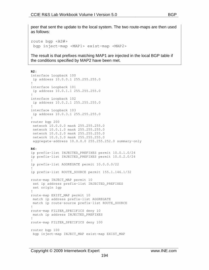
CCIE R&S Lab Workbook Volume I Version 5.0 BGP
Copyright © 2009 Internetwork Expert www.INE.com194
peer that sent the update to the local system. The two route-maps are then used as follows:
route bgp <AS#> bgp inject-map <MAP1> exist-map <MAP2>
The result is that prefixes matching MAP1 are injected in the local BGP table if the conditions specified by MAP2 have been met.
R2: interface Loopback 100 ip address 10.0.0.1 255.255.255.0 ! interface Loopback 101 ip address 10.0.1.1 255.255.255.0 ! interface Loopback 102 ip address 10.0.2.1 255.255.255.0 ! interface Loopback 103 ip address 10.0.3.1 255.255.255.0 ! router bgp 200 network 10.0.0.0 mask 255.255.255.0 network 10.0.1.0 mask 255.255.255.0 network 10.0.2.0 mask 255.255.255.0 network 10.0.3.0 mask 255.255.255.0 aggregate-address 10.0.0.0 255.255.252.0 summary-only
R6: ip prefix-list INJECTED_PREFIXES permit 10.0.1.0/24 ip prefix-list INJECTED_PREFIXES permit 10.0.2.0/24 ! ip prefix-list AGGREGATE permit 10.0.0.0/22 ! ip prefix-list ROUTE_SOURCE permit 155.1.146.1/32
route-map INJECT_MAP permit 10 set ip address prefix-list INJECTED_PREFIXES set origin igp ! route-map EXIST_MAP permit 10 match ip address prefix-list AGGREGATE match ip route-source prefix-list ROUTE_SOURCE ! route-map FILTER_SPECIFICS deny 10 match ip address INJECTED_PREFIXES ! route-map FILTER_SPECIFICS deny 100
router bgp 100 bgp inject-map INJECT_MAP exist-map EXIST_MAP
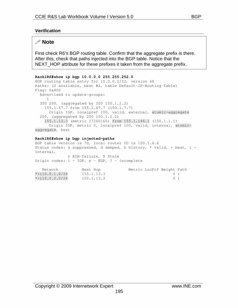
CCIE R&S Lab Workbook Volume I Version 5.0 BGP
Copyright © 2009 Internetwork Expert www.INE.com195
Verification
Note
First check R6’s BGP routing table. Confirm that the aggregate prefix is there. After this, check that paths injected into the BGP table. Notice that the NEXT_HOP attribute for these prefixes it taken from the aggregate prefix.
Rack1R6#show ip bgp 10.0.0.0 255.255.252.0 BGP routing table entry for 10.0.0.0/22, version 68 Paths: (2 available, best #2, table Default-IP-Routing-Table) Flag: 0x800 Advertised to update-groups: 1 300 200, (aggregated by 200 150.1.2.2) 155.1.67.7 from 155.1.67.7 (150.1.7.7) Origin IGP, localpref 100, valid, external, atomic-aggregate 200, (aggregated by 200 150.1.2.2) 155.1.13.3 (metric 27260160) from 155.1.146.1 (150.1.1.1) Origin IGP, metric 0, localpref 100, valid, internal, atomic-aggregate, best
Rack1R6#show ip bgp injected-paths BGP table version is 70, local router ID is 150.1.6.6 Status codes: s suppressed, d damped, h history, * valid, > best, i - internal, r RIB-failure, S Stale Origin codes: i - IGP, e - EGP, ? - incomplete
Network Next Hop Metric LocPrf Weight Path *>i10.0.1.0/24 155.1.13.3 0 i *>i10.0.2.0/24 155.1.13.3 0 i
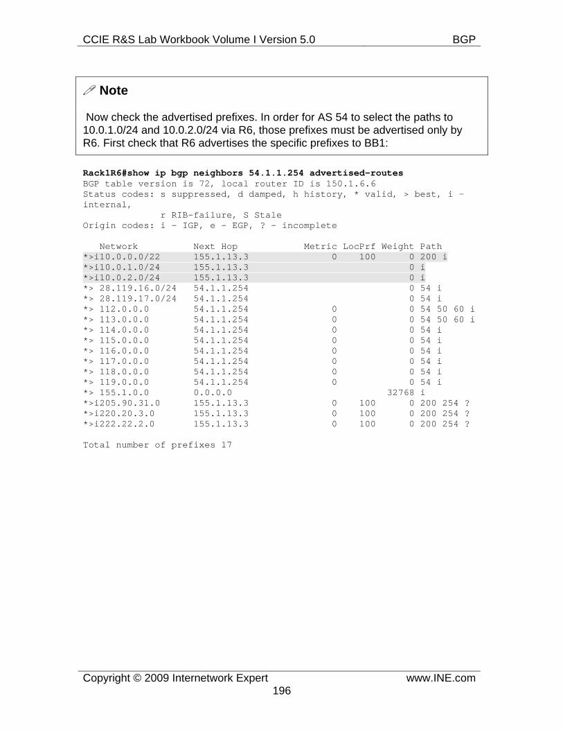
CCIE R&S Lab Workbook Volume I Version 5.0 BGP
Copyright © 2009 Internetwork Expert www.INE.com196
Note
Now check the advertised prefixes. In order for AS 54 to select the paths to 10.0.1.0/24 and 10.0.2.0/24 via R6, those prefixes must be advertised only by R6. First check that R6 advertises the specific prefixes to BB1:
Rack1R6#show ip bgp neighbors 54.1.1.254 advertised-routes BGP table version is 72, local router ID is 150.1.6.6 Status codes: s suppressed, d damped, h history, * valid, > best, i - internal, r RIB-failure, S Stale Origin codes: i - IGP, e - EGP, ? - incomplete
Network Next Hop Metric LocPrf Weight Path *>i10.0.0.0/22 155.1.13.3 0 100 0 200 i *>i10.0.1.0/24 155.1.13.3 0 i *>i10.0.2.0/24 155.1.13.3 0 i *> 28.119.16.0/24 54.1.1.254 0 54 i *> 28.119.17.0/24 54.1.1.254 0 54 i *> 112.0.0.0 54.1.1.254 0 0 54 50 60 i *> 113.0.0.0 54.1.1.254 0 0 54 50 60 i *> 114.0.0.0 54.1.1.254 0 0 54 i *> 115.0.0.0 54.1.1.254 0 0 54 i *> 116.0.0.0 54.1.1.254 0 0 54 i *> 117.0.0.0 54.1.1.254 0 0 54 i *> 118.0.0.0 54.1.1.254 0 0 54 i *> 119.0.0.0 54.1.1.254 0 0 54 i *> 155.1.0.0 0.0.0.0 32768 i *>i205.90.31.0 155.1.13.3 0 100 0 200 254 ? *>i220.20.3.0 155.1.13.3 0 100 0 200 254 ? *>i222.22.2.0 155.1.13.3 0 100 0 200 254 ?
Total number of prefixes 17
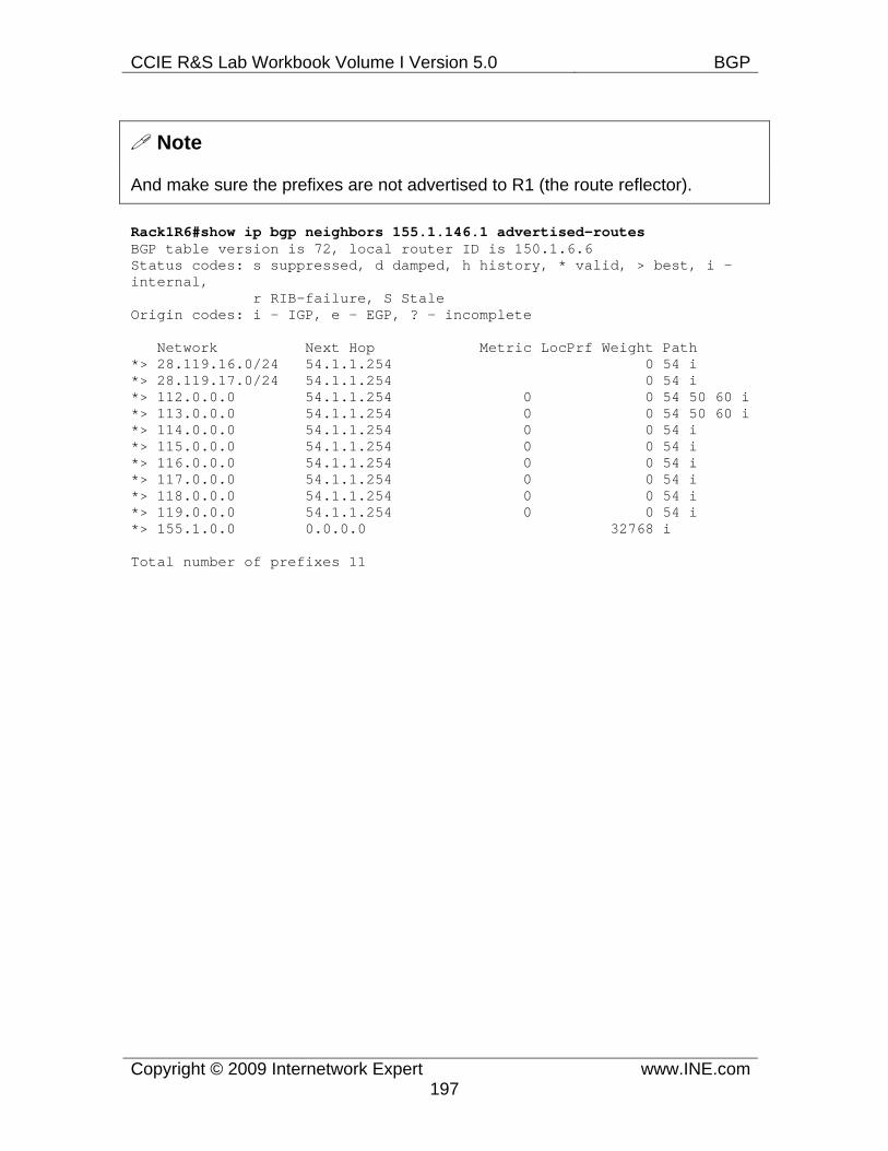
CCIE R&S Lab Workbook Volume I Version 5.0 BGP
Copyright © 2009 Internetwork Expert www.INE.com197
Note
And make sure the prefixes are not advertised to R1 (the route reflector).
Rack1R6#show ip bgp neighbors 155.1.146.1 advertised-routes BGP table version is 72, local router ID is 150.1.6.6 Status codes: s suppressed, d damped, h history, * valid, > best, i - internal, r RIB-failure, S Stale Origin codes: i - IGP, e - EGP, ? - incomplete
Network Next Hop Metric LocPrf Weight Path *> 28.119.16.0/24 54.1.1.254 0 54 i *> 28.119.17.0/24 54.1.1.254 0 54 i *> 112.0.0.0 54.1.1.254 0 0 54 50 60 i *> 113.0.0.0 54.1.1.254 0 0 54 50 60 i *> 114.0.0.0 54.1.1.254 0 0 54 i *> 115.0.0.0 54.1.1.254 0 0 54 i *> 116.0.0.0 54.1.1.254 0 0 54 i *> 117.0.0.0 54.1.1.254 0 0 54 i *> 118.0.0.0 54.1.1.254 0 0 54 i *> 119.0.0.0 54.1.1.254 0 0 54 i *> 155.1.0.0 0.0.0.0 32768 i
Total number of prefixes 11
CCIE R&S Lab Workbook Volume I Version 5.0 BGP
Copyright © 2009 Internetwork Expert www.INE.com198
7.44 BGP Filtering with Prefix-Lists • Configure a prefix-list on R2 so that it does not accept the prefix
222.22.2.0/24 from BB2; this prefix-list should be applied directly to the neighbor.
• Configure a prefix-list on R4 so that it does not accept any prefixes with a subnet mask greater than /22 from BB3; this prefix-list should be applied through a route-map to the neighbor.
Configuration
Note
Prefix lists are the most preferable way to filter subnets in BGP based on their IP addressing information. Prefix list is an ordered sequence of entries, where each entry specifies either a single IP prefix or a range of prefixes. Prefix lists are stored in efficient data structures allowing for very fast lookup and information retrieval. They have certain performance benefits over the standard and extended IOS access-lists when used for prefix filtering. Here is the syntax for a typical prefix-list entry:
ip prefix-list <NAME> seq <Num> {permit|deny} <Subnet>/<Prefix > [ge <Length1>] [le <Length2>]
Entries in a prefix list are processed sequentially, until the first match. As soon as the match is found, the processing is stopped and associated action performed. The <Subnet>/<Prefix> pair specifies the major subnet that all prefix matching this entry should belong to. For example this could be 192.168.0.0/16 or 172.16.8.0/24 and so on – any valid classless prefix. The modifiers ge and le are optional and used to specify a prefix range. Specifically, a prefix matches the entry if:
a) The prefix is a subnet of <Subnet>/<Prefix>, i.e. the prefix subnet is a subset of <Subnet> and prefix-length is greater than or equal than <Prefix>.
b) The prefix length is less than or equal to <Length2>. That is, if the lemodifier is used, then the prefix length must be within the [<Prefix>, <Length2>] range. For example, with 192.168.0.0/16 le 24 an example of valid prefix is 192.168.2.0/24 or 192.168.0.0/22 as both prefixes are subnets to 192.168.0.0/16 and have prefix-length less than or equal to 24. However, 192.168.2.128/25 will not match the above prefix-list entry.
c) The prefix length is greater than or equal to <Length1> but less than 32 is the ge modifier is used. That is, the prefix-length should be within the
CCIE R&S Lab Workbook Volume I Version 5.0 BGP
Copyright © 2009 Internetwork Expert www.INE.com199
[<Length1>,32] range. It’s is obvious that <Length1> should be greater than or equal than <Prefix>. Take for example prefix-list entry 172.16.3.0/24 ge 25. It would match 172.16.3.128/25, 172.16.3.0/30, 172.16.3.1/32 but not the 172.16.3.0/24.
If both le and ge modifiers are in use, the resulting prefix-length range is between <Length1> and <Length2> inclusive. For example, 172.16.0.0/16 ge 24 le 30 would match 172.16.0.0/24, 172.16.3.0/24, 172.16.3.252/30 and so on.
Two common questions with prefix-lists is how to match the default route and match all prefixes. The entries are permit 0.0.0.0/0 and permit 0.0.0.0/0 le 32 respectively. The first entry matches the prefix with the prefix-length of zero and the network part of 0.0.0.0. The second entry matches any subnet of 0.0.0.0/0 which encompasses the whole IPv4 address space.
Prefix lists could be applied directly to a BGP peer using the command neighbor <IP> prefix-list <NAME {in|out} or using a route-map matching the prefix-list. The latter is a preferable way, as it allows you for more flexible policy editing.
R2: ip prefix-list BLOCK_222 deny 222.22.2.0/24 ip prefix-list BLOCK_222 permit 0.0.0.0/0 le 32 ! router bgp 200 neighbor 192.10.1.254 prefix-list BLOCK_222 in
R4: ip prefix-list SHORTER_THAN_22 permit 0.0.0.0/0 le 22 ! route-map FROM_BB3 permit 100 match ip address prefix-list SHORTER_THAN_22 ! router bgp 100 neighbor 204.12.1.254 route-map FROM_BB3 in
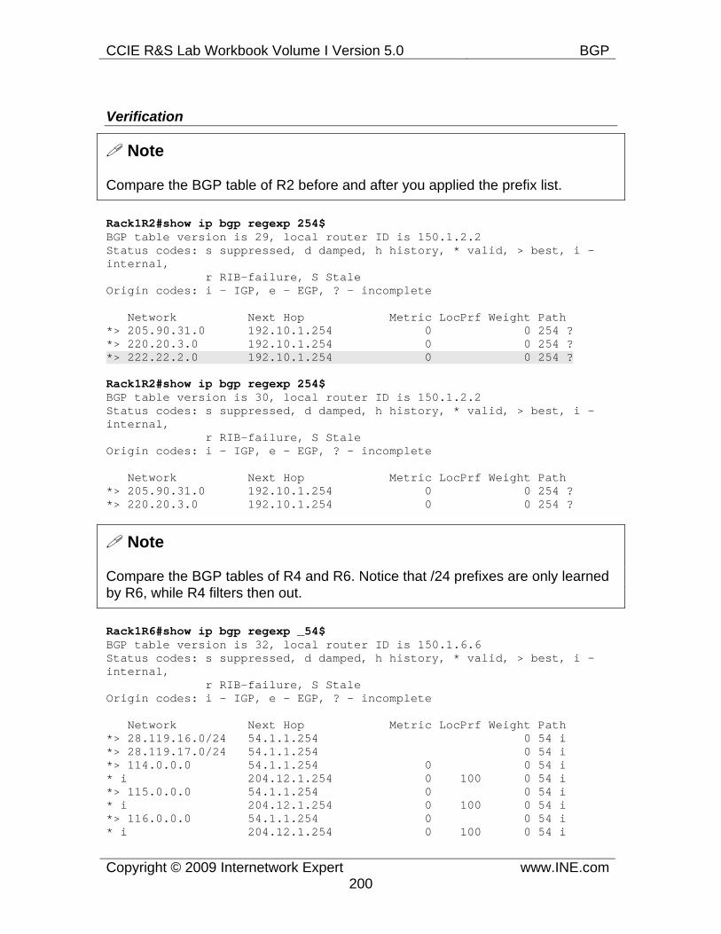
CCIE R&S Lab Workbook Volume I Version 5.0 BGP
Copyright © 2009 Internetwork Expert www.INE.com200
Verification
Note
Compare the BGP table of R2 before and after you applied the prefix list.
Rack1R2#show ip bgp regexp 254$ BGP table version is 29, local router ID is 150.1.2.2 Status codes: s suppressed, d damped, h history, * valid, > best, i - internal, r RIB-failure, S Stale Origin codes: i - IGP, e - EGP, ? - incomplete
Network Next Hop Metric LocPrf Weight Path *> 205.90.31.0 192.10.1.254 0 0 254 ? *> 220.20.3.0 192.10.1.254 0 0 254 ? *> 222.22.2.0 192.10.1.254 0 0 254 ?
Rack1R2#show ip bgp regexp 254$ BGP table version is 30, local router ID is 150.1.2.2 Status codes: s suppressed, d damped, h history, * valid, > best, i - internal, r RIB-failure, S Stale Origin codes: i - IGP, e - EGP, ? - incomplete
Network Next Hop Metric LocPrf Weight Path *> 205.90.31.0 192.10.1.254 0 0 254 ? *> 220.20.3.0 192.10.1.254 0 0 254 ?
Note
Compare the BGP tables of R4 and R6. Notice that /24 prefixes are only learned by R6, while R4 filters then out.
Rack1R6#show ip bgp regexp _54$ BGP table version is 32, local router ID is 150.1.6.6 Status codes: s suppressed, d damped, h history, * valid, > best, i - internal, r RIB-failure, S Stale Origin codes: i - IGP, e - EGP, ? - incomplete
Network Next Hop Metric LocPrf Weight Path *> 28.119.16.0/24 54.1.1.254 0 54 i *> 28.119.17.0/24 54.1.1.254 0 54 i *> 114.0.0.0 54.1.1.254 0 0 54 i * i 204.12.1.254 0 100 0 54 i *> 115.0.0.0 54.1.1.254 0 0 54 i * i 204.12.1.254 0 100 0 54 i *> 116.0.0.0 54.1.1.254 0 0 54 i * i 204.12.1.254 0 100 0 54 i
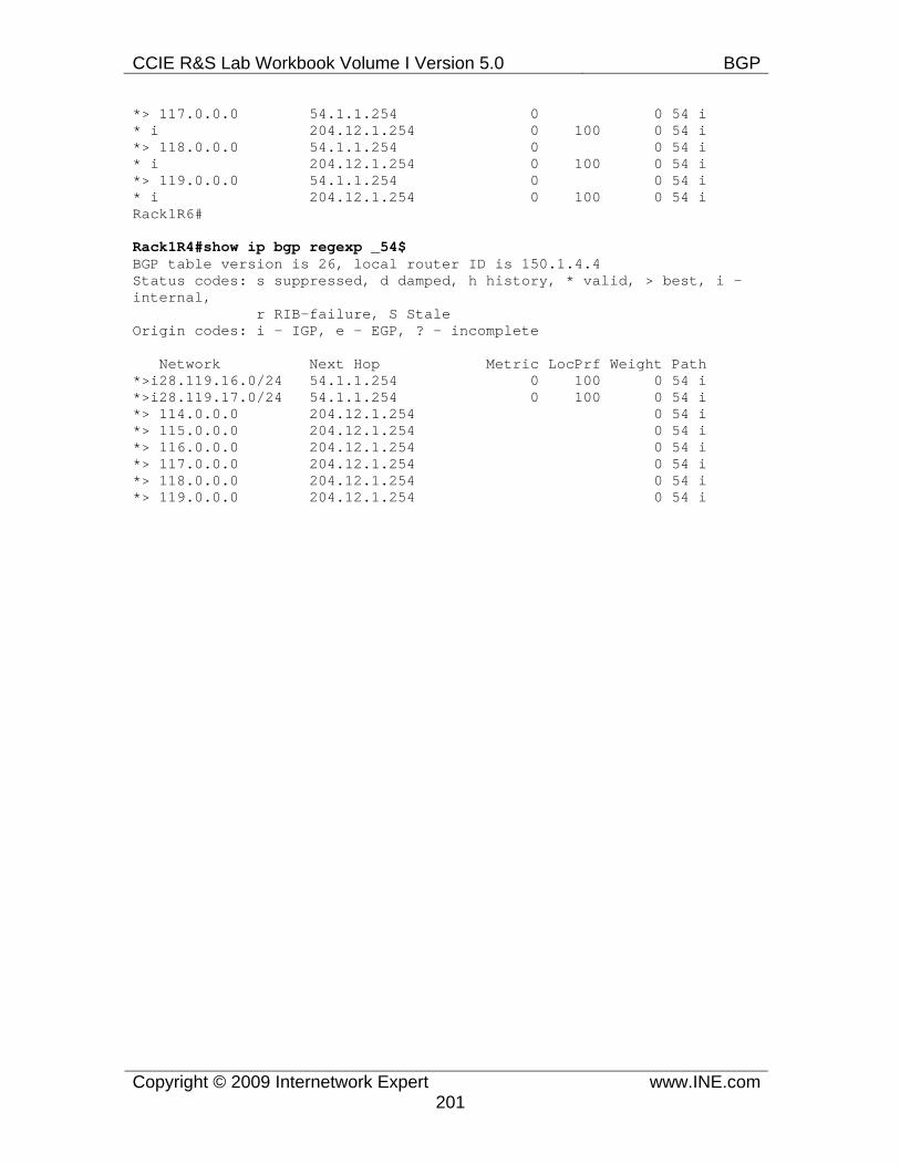
CCIE R&S Lab Workbook Volume I Version 5.0 BGP
Copyright © 2009 Internetwork Expert www.INE.com201
*> 117.0.0.0 54.1.1.254 0 0 54 i * i 204.12.1.254 0 100 0 54 i *> 118.0.0.0 54.1.1.254 0 0 54 i * i 204.12.1.254 0 100 0 54 i *> 119.0.0.0 54.1.1.254 0 0 54 i * i 204.12.1.254 0 100 0 54 i Rack1R6#
Rack1R4#show ip bgp regexp _54$ BGP table version is 26, local router ID is 150.1.4.4 Status codes: s suppressed, d damped, h history, * valid, > best, i - internal, r RIB-failure, S Stale Origin codes: i - IGP, e - EGP, ? - incomplete
Network Next Hop Metric LocPrf Weight Path *>i28.119.16.0/24 54.1.1.254 0 100 0 54 i *>i28.119.17.0/24 54.1.1.254 0 100 0 54 i *> 114.0.0.0 204.12.1.254 0 54 i *> 115.0.0.0 204.12.1.254 0 54 i *> 116.0.0.0 204.12.1.254 0 54 i *> 117.0.0.0 204.12.1.254 0 54 i *> 118.0.0.0 204.12.1.254 0 54 i *> 119.0.0.0 204.12.1.254 0 54 i
CCIE R&S Lab Workbook Volume I Version 5.0 BGP
Copyright © 2009 Internetwork Expert www.INE.com202
7.45 BGP Filtering with Standard Access-Lists • Configure a standard access-list on R2 so that it does not accept any
prefix with the address 222.22.2.0 from BB2; this access-list should be applied directly to the neighbor.
• Configure a standard access-list on R4 so that it does not accept any prefixes with an odd number in the first octet; this access-list should be applied through a route-map to the neighbor.
Configuration
Note
Using standard access-list for BGP filtering is not as performance-effective as using prefix lists. In addition, a standard access-list does not allow you specifying the prefix-length, only the subnet numbers. Still, this approach offers some unique features not available with prefix-lists, such as selecting a range of subnet numbers.
As you remember, a standard access-list selects a subnet based on the pre-defined number and a wildcard mask. The wildcard mask is a 32-bit value that specifies the bits in the subnet numbers to be ignored. If a bit in the wildcard mask is 0, then the respective subnet bit value is “fixed”. If a bit in the wildcard mask is 1, then the respective subnet bit value could be either 0 or 1. For example, take the combination 192.168.0.0 0.0.255.255. Leading 16 bits of the subnet number are fixed at their value of “192.168”. However, the remaining 16 bits could take any value, as the wildcard mask bits are all ones. Thus the construct would match 192.168.0.1, 192.168.2.0, 192.168.32.128 and so on.
Since the wildcard mask does not represent the prefix subnet mask, you may make it discontinuous. This allows for some “oddball” filtering, such as permitting odd/even prefixes. Due to the binary nature of the wildcard mask, the number of prefixes selected is always a power of 2, i.e. 2^0, 2^1, 2^2 and so on. For example, the following combination “23.0.1.0 14.0.0.255” would match 8x256 subnets (3 bits set to one in the first octet and 8 bits set to 1 in the last octet) such as 23.0.1.64, 21.0.1.128, 17.0.1.32 and so on. The key is to transform the subnet number into binary format and apply the wildcard mask by walking over all possible combinations.
In this scenario we create an access-list that matches all prefixes with the odd first octet. This means the first octet must always have the lowest-significant bit set to one. This results in the corresponding wildcard bit set to 0 all the time. All other bits don’t matter, so we can set the remaining wildcard bits to ones. The resulting combination is “1.0.0.0 254.255.255.255”.
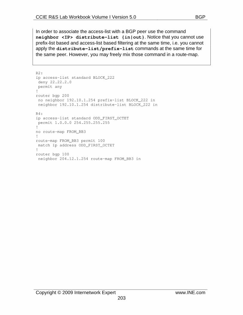
CCIE R&S Lab Workbook Volume I Version 5.0 BGP
Copyright © 2009 Internetwork Expert www.INE.com203
In order to associate the access-list with a BGP peer use the command neighbor <IP> distribute-list {in|out}. Notice that you cannot use prefix-list based and access-list based filtering at the same time, i.e. you cannot apply the distribute-list/prefix-list commands at the same time for the same peer. However, you may freely mix those command in a route-map.
R2: ip access-list standard BLOCK_222 deny 22.22.2.0 permit any ! router bgp 200 no neighbor 192.10.1.254 prefix-list BLOCK_222 in neighbor 192.10.1.254 distribute-list BLOCK_222 in
R4: ip access-list standard ODD_FIRST_OCTET permit 1.0.0.0 254.255.255.255 ! no route-map FROM_BB3 ! route-map FROM_BB3 permit 100 match ip address ODD_FIRST_OCTET ! router bgp 100 neighbor 204.12.1.254 route-map FROM_BB3 in
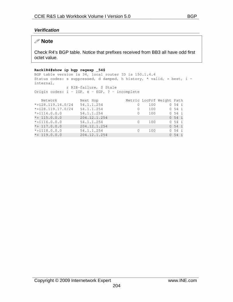
CCIE R&S Lab Workbook Volume I Version 5.0 BGP
Copyright © 2009 Internetwork Expert www.INE.com204
Verification
Note
Check R4’s BGP table. Notice that prefixes received from BB3 all have odd first octet value.
Rack1R4#show ip bgp regexp _54$ BGP table version is 34, local router ID is 150.1.4.4 Status codes: s suppressed, d damped, h history, * valid, > best, i - internal, r RIB-failure, S Stale Origin codes: i - IGP, e - EGP, ? - incomplete
Network Next Hop Metric LocPrf Weight Path *>i28.119.16.0/24 54.1.1.254 0 100 0 54 i *>i28.119.17.0/24 54.1.1.254 0 100 0 54 i *>i114.0.0.0 54.1.1.254 0 100 0 54 i *> 115.0.0.0 204.12.1.254 0 54 i *>i116.0.0.0 54.1.1.254 0 100 0 54 i *> 117.0.0.0 204.12.1.254 0 54 i *>i118.0.0.0 54.1.1.254 0 100 0 54 i *> 119.0.0.0 204.12.1.254 0 54 i
CCIE R&S Lab Workbook Volume I Version 5.0 BGP
Copyright © 2009 Internetwork Expert www.INE.com205
7.46 BGP Filtering with Extended Access-Lists • Modify the filtering configuration in R4 as follows. • Configure an extended access-list on R4 so that it does not accept any
prefixes with even 3rd octet and with a subnet mask greater than /22 from BB3.
• This list should apply directly to the neighbor.
Configuration
Note
Extended access-lists add more functionality to BGP prefixes filtering. In addition to matching the subnet numbers they allows for subnet mask matching as well. A typical extended access-list entry in the format
permit {proto} <src-subnet> <src-mask> <dst-subnet> <dst-mask> [options]
is treated as follows. First, the protocol field and other options are ignored. Next, <src-subnet> <src-mask> pair is used to build an expression for prefix subnet matching. The pair <dst-subnet> <dst-mask> is used as an expression to match prefixes subnet mask. For example the statement
permit ip 192.168.0.0 0.0.0.255 255.255.255.0 0.0.0.255
would match any prefix with the subnet number in range 192.168.0.0-192.168.0.255 AND having the prefix length of /24 or greater. It is possible to use more sophisticated constructs based on the wildcard bits logic, but this usually makes the configuration hard to read and interpret. Here are more examples:
permit ip 10.0.0.0 0.0.0.0 255.255.0.0 0.0.0.0 - matches 10.0.0.0/16 - Only
permit ip 10.0.0.0 0.0.0.0 255.255.255.0 0.0.0.0 - matches 10.0.0.0/24 - Only
permit ip 10.1.1.0 0.0.0.0 255.255.255.0 0.0.0.0 - matches 10.1.1.0/24 - Only
permit ip 10.0.0.0 0.0.255.0 255.255.255.0 0.0.0.0 - matches 10.0.X.0/24 - Any number in the 3rd octet of the network with a /24 subnet mask.
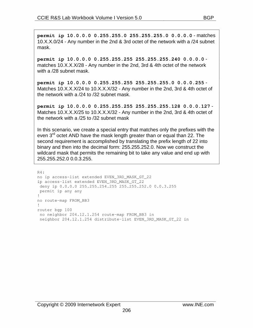
CCIE R&S Lab Workbook Volume I Version 5.0 BGP
Copyright © 2009 Internetwork Expert www.INE.com206
permit ip 10.0.0.0 0.255.255.0 255.255.255.0 0.0.0.0 - matches 10.X.X.0/24 - Any number in the 2nd & 3rd octet of the network with a /24 subnet mask.
permit ip 10.0.0.0 0.255.255.255 255.255.255.240 0.0.0.0 - matches 10.X.X.X/28 - Any number in the 2nd, 3rd & 4th octet of the network with a /28 subnet mask.
permit ip 10.0.0.0 0.255.255.255 255.255.255.0 0.0.0.255 - Matches 10.X.X.X/24 to 10.X.X.X/32 - Any number in the 2nd, 3rd & 4th octet of the network with a /24 to /32 subnet mask.
permit ip 10.0.0.0 0.255.255.255 255.255.255.128 0.0.0.127 - Matches 10.X.X.X/25 to 10.X.X.X/32 - Any number in the 2nd, 3rd & 4th octet of the network with a /25 to /32 subnet mask
In this scenario, we create a special entry that matches only the prefixes with the even 3rd octet AND have the mask length greater than or equal than 22. The second requirement is accomplished by translating the prefix length of 22 into binary and then into the decimal form: 255.255.252.0. Now we construct the wildcard mask that permits the remaining bit to take any value and end up with 255.255.252.0 0.0.3.255.
R4: no ip access-list extended EVEN_3RD_MASK_GT_22 ip access-list extended EVEN_3RD_MASK_GT_22 deny ip 0.0.0.0 255.255.254.255 255.255.252.0 0.0.3.255 permit ip any any ! no route-map FROM_BB3 ! router bgp 100 no neighbor 204.12.1.254 route-map FROM_BB3 in neighbor 204.12.1.254 distribute-list EVEN_3RD_MASK_GT_22 in
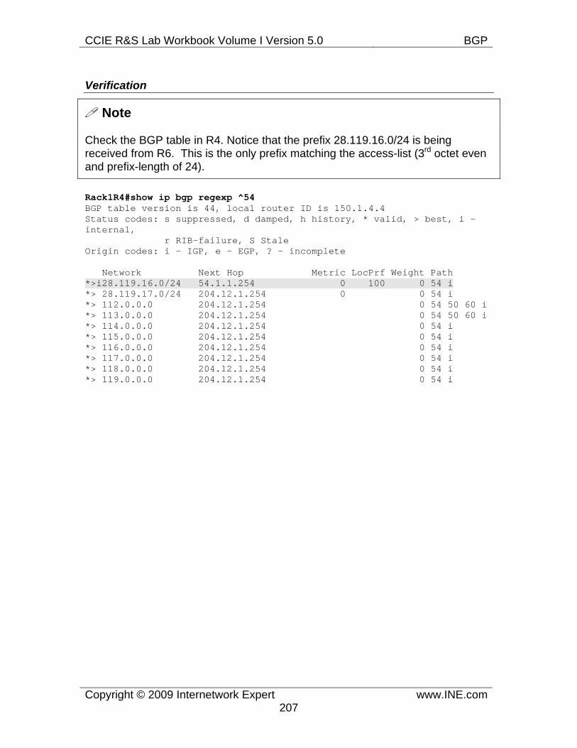
CCIE R&S Lab Workbook Volume I Version 5.0 BGP
Copyright © 2009 Internetwork Expert www.INE.com207
Verification
Note
Check the BGP table in R4. Notice that the prefix 28.119.16.0/24 is being received from R6. This is the only prefix matching the access-list (3rd octet even and prefix-length of 24).
Rack1R4#show ip bgp regexp ^54 BGP table version is 44, local router ID is 150.1.4.4 Status codes: s suppressed, d damped, h history, * valid, > best, i - internal, r RIB-failure, S Stale Origin codes: i - IGP, e - EGP, ? - incomplete
Network Next Hop Metric LocPrf Weight Path *>i28.119.16.0/24 54.1.1.254 0 100 0 54 i *> 28.119.17.0/24 204.12.1.254 0 0 54 i *> 112.0.0.0 204.12.1.254 0 54 50 60 i *> 113.0.0.0 204.12.1.254 0 54 50 60 i *> 114.0.0.0 204.12.1.254 0 54 i *> 115.0.0.0 204.12.1.254 0 54 i *> 116.0.0.0 204.12.1.254 0 54 i *> 117.0.0.0 204.12.1.254 0 54 i *> 118.0.0.0 204.12.1.254 0 54 i *> 119.0.0.0 204.12.1.254 0 54 i
CCIE R&S Lab Workbook Volume I Version 5.0 BGP
Copyright © 2009 Internetwork Expert www.INE.com208
7.47 BGP Regular Expressions • Create a new Loopback1 on each device with IP addresses in the format
Y.Y.Y.Y/32, where Y is your device number, and advertise them into BGP. • Configure an AS-Path access-list on SW1 so that AS 300 cannot be used
as transit for AS 100 to reach AS 200 or vice-versa; this access-list should be applied directly to its neighbors.
• Configure a local-preference modification on R5 such that traffic from AS 200 going to route originated in AS 54 is always sent to R4, while traffic to routes that transit AS 54 but were not originated in AS 54 is always sent to R3.
• Additionally configure R3 so that routes learned from AS 254 are not advertised to R1
Configuration
Note
Filtering based on AS_PATH attribute is done using BGP regular expressions. Regular expressions are matched against the AS_PATH strings. As you remember, AS_PATH could be constructed of the following elements: AS_SET (unordered list of AS numbers), AS_SEQUENCE (ordered list of AS numbers), AS_CONFED_SET and AS_CONFED_SEQUENCE which are the same elements but consist of the confederation AS numbers. For the purpose of matching, the AS_PATH attribute is viewed as a string starting with the adjacent AS number on the leftmost position, and the originating AS number in the rightmost position. When matching the AS_SET attribute, enclose the AS numbers in curly brackets and separate them by commas, e.g. {100,200,300}. When matching a confederation path, enclose the AS numbers in parenthesis, using backslash to escape the special meaning of the character: “\(100\)”.
We are going to discuss the most useful types of regexp patterns suitable for many “real-life” situations. You may read more about BGP regular expressions basics in our blog post Understanding BGP Regular Expressions. First, recall the basic regular expression meta-characters or modifiers: “.” – any character, “?” – repeat the previous character one or zero times, “*” – repeat the previous character zero or any times, “+” – repeat the previous character one or more times, “^” – match the beginning of a string, “$” match the end of a string, “[]” means range or elements and “_” is the character to match the “space” separating AS numbers OR the end of the AS_PATH list.
Other important regexp features include grouping and back-referencing. You can use parentheses to group AS numbers, e.g. (123 124 1+) and every group is assigned a number starting from left to right. For example in the string “1 2 (3 4)
CCIE R&S Lab Workbook Volume I Version 5.0 BGP
Copyright © 2009 Internetwork Expert www.INE.com209
5 6 (7 8)” the first group is assigned number “1” and the second group number “2”. You can later “recall” the grouping using the commands \1, \2 and so on for the group numbers. For example the string “(1 2) 3 \1” would match “1 2 3 1 2”. You may use the pipe character “|” in addition to the grouping characters for the concept of alternation. For example (1 2)|(5 6) would match “1 2” or “5 6”.
Now the practical examples:
“^$” - means empty AS_PATH attribute, which identifies the prefixes advertised in the local AS.
“^254_” - means prefixes received from the directly adjacent AS 254. Notice that using “_” is important, as there could be another adjacent AS with the number starting with 254.
“_254_” - prefixes transiting AS 254. The “_” characters are needed to clearly separate the AS number.
“_254$” - means prefixes originated in the AS 254. This expression matches the rightmost position in the string, meaning that the expression could be of arbitrary length.
“^([0-9]+)_254” - routes from the AS 254 when it’s just “one-hop” away.
“^254_([0-9]+)” - prefixes from the clients of the directly connected AS 254.
“^(254_)+([0-9]+)” - prefixes from the clients of the adjacent AS 254, accounting for the fact that AS 254 may do AS_PATH prepending.
“^254_([0-9]+_)+” - prefixes from the clients of the adjacent AS 254, accounting for the fact that the clients may do AS_PATH prepending.
^\(65100\) – prefixes learned from the confederation peer 65100.
You configure BGP regular-expression using the IP AS-PATH access-lists: ip as-path access-list <N> {permit|deny} <Regexp>. This access-list might be applied as a filter-list to a peer using the syntax: neighbor <IP> filter-list <N> {in|out}. However, the best approach is to match AS_PATH access-lists under a route-map applied to the peer (match as-path), as this allows for flexible policy editing. If you are wondering about the order features are applied, it is as follows:
For inbound updates:
CCIE R&S Lab Workbook Volume I Version 5.0 BGP
Copyright © 2009 Internetwork Expert www.INE.com210
1. route-map 2. filter-list 3. prefix-list OR distribute-list
For outbound updates:
1. prefix-list OR distribute-list 2. filter-list 3. route-map
Keep in mind that you may test regular expression on the BGP table using the command show ip bgp regexp or show ip bgp quote-regexp. The latter command allows using the “|” character to additionally filter the output.
R1: interface Loopback 1 ip address 1.1.1.1 255.255.255.0 ! router bgp 100 network 1.1.1.0 mask 255.255.255.0
R2: interface Loopback 1 ip address 2.2.2.2 255.255.255.0 ! router bgp 200 network 2.2.2.0 mask 255.255.255.0
R3: interface Loopback 1 ip address 3.3.3.3 255.255.255.0 ! no ip as-path access-list 1 ip as-path access-list 1 deny 54$ ip as-path access-list 1 permit _54_ ! ip as-path access-list 2 permit 254$ ! route-map FROM_R1 permit 10 match as-path 1 set local-preference 200 ! route-map FROM_R1 permit 100
! ! !
route-map TO_R1 deny 10 match as-path 2
CCIE R&S Lab Workbook Volume I Version 5.0 BGP
Copyright © 2009 Internetwork Expert www.INE.com211
! route-map TO_R1 permit 100
! ! !
router bgp 200 network 3.3.3.0 mask 255.255.255.0 neighbor 155.1.13.1 route-map FROM_R1 in neighbor 155.1.13.1 route-map TO_R1 out
R4: interface Loopback 1 ip address 4.4.4.4 255.255.255.0 ! router bgp 100 network 4.4.4.0 mask 255.255.255.0
R5: interface Loopback 1 ip address 5.5.5.5 255.255.255.0 ! ip as-path access-list 1 permit _54$ ! route-map FROM_R4 permit 10 match as-path 1 set local-preference 200 ! route-map FROM_R4 permit 100 ! router bgp 200 network 5.5.5.0 mask 255.255.255.0 neighbor 155.1.45.4 route-map FROM_R4 in
R6: interface Loopback 1 ip address 6.6.6.6 255.255.255.0 ! router bgp 100 network 6.6.6.0 mask 255.255.255.0
SW1: ip as-path access-list 1 permit ^$ ! route-map NO_TRANSIT permit 100 match as-path 1 ! router bgp 300 neighbor 155.1.67.6 route-map NO_TRANSIT out neighbor 155.1.37.3 route-map NO_TRANSIT out
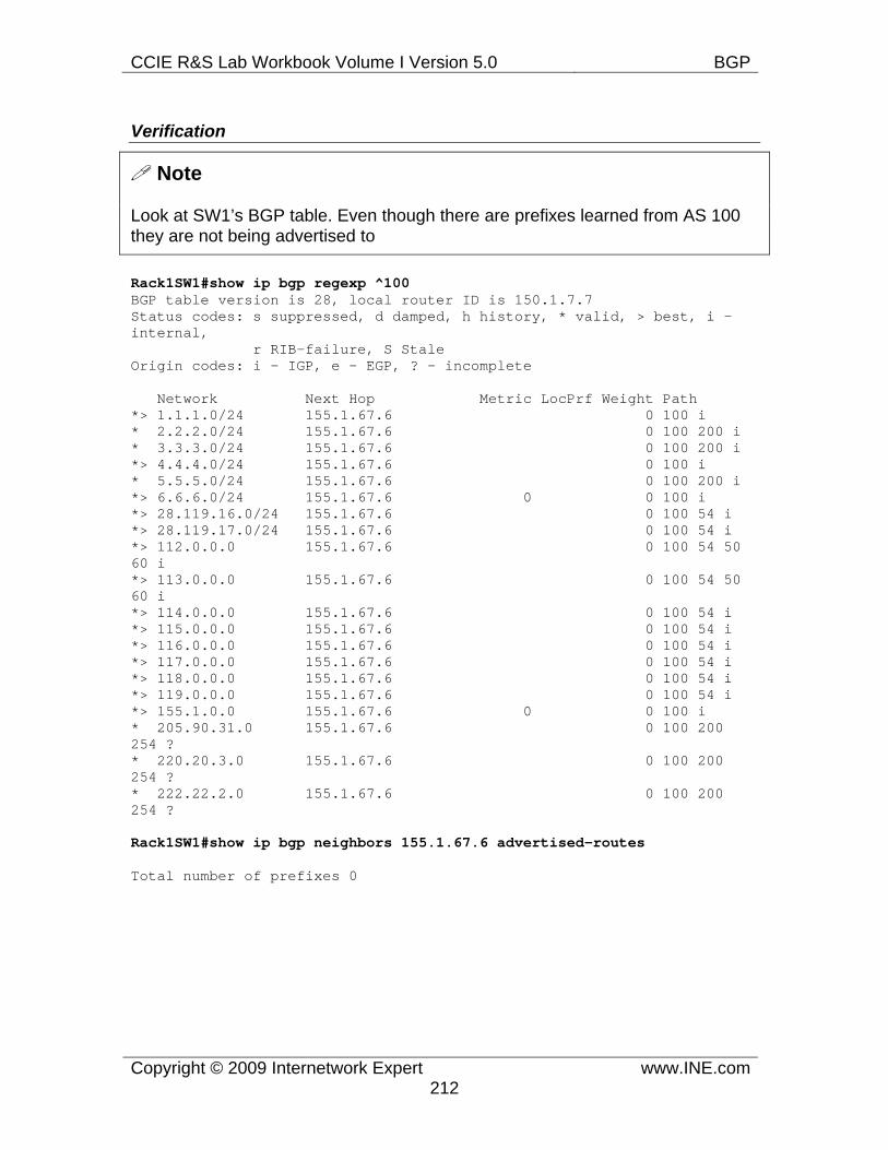
CCIE R&S Lab Workbook Volume I Version 5.0 BGP
Copyright © 2009 Internetwork Expert www.INE.com212
Verification
Note
Look at SW1’s BGP table. Even though there are prefixes learned from AS 100 they are not being advertised to
Rack1SW1#show ip bgp regexp ^100 BGP table version is 28, local router ID is 150.1.7.7 Status codes: s suppressed, d damped, h history, * valid, > best, i - internal, r RIB-failure, S Stale Origin codes: i - IGP, e - EGP, ? - incomplete
Network Next Hop Metric LocPrf Weight Path *> 1.1.1.0/24 155.1.67.6 0 100 i * 2.2.2.0/24 155.1.67.6 0 100 200 i * 3.3.3.0/24 155.1.67.6 0 100 200 i *> 4.4.4.0/24 155.1.67.6 0 100 i * 5.5.5.0/24 155.1.67.6 0 100 200 i *> 6.6.6.0/24 155.1.67.6 0 0 100 i *> 28.119.16.0/24 155.1.67.6 0 100 54 i *> 28.119.17.0/24 155.1.67.6 0 100 54 i *> 112.0.0.0 155.1.67.6 0 100 54 50 60 i *> 113.0.0.0 155.1.67.6 0 100 54 50 60 i *> 114.0.0.0 155.1.67.6 0 100 54 i *> 115.0.0.0 155.1.67.6 0 100 54 i *> 116.0.0.0 155.1.67.6 0 100 54 i *> 117.0.0.0 155.1.67.6 0 100 54 i *> 118.0.0.0 155.1.67.6 0 100 54 i *> 119.0.0.0 155.1.67.6 0 100 54 i *> 155.1.0.0 155.1.67.6 0 0 100 i * 205.90.31.0 155.1.67.6 0 100 200 254 ? * 220.20.3.0 155.1.67.6 0 100 200 254 ? * 222.22.2.0 155.1.67.6 0 100 200 254 ?
Rack1SW1#show ip bgp neighbors 155.1.67.6 advertised-routes
Total number of prefixes 0
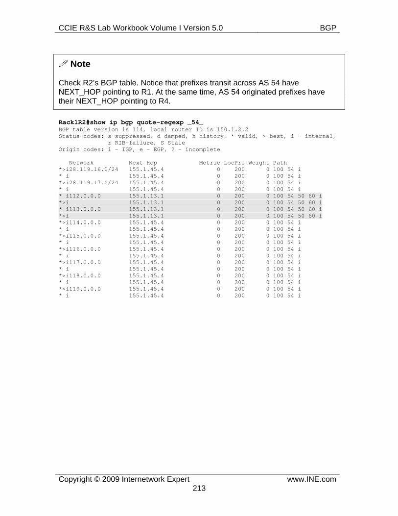
CCIE R&S Lab Workbook Volume I Version 5.0 BGP
Copyright © 2009 Internetwork Expert www.INE.com213
Note
Check R2’s BGP table. Notice that prefixes transit across AS 54 have NEXT_HOP pointing to R1. At the same time, AS 54 originated prefixes have their NEXT_HOP pointing to R4.
Rack1R2#show ip bgp quote-regexp _54_ BGP table version is 114, local router ID is 150.1.2.2 Status codes: s suppressed, d damped, h history, * valid, > best, i - internal, r RIB-failure, S Stale Origin codes: i - IGP, e - EGP, ? - incomplete
Network Next Hop Metric LocPrf Weight Path *>i28.119.16.0/24 155.1.45.4 0 200 0 100 54 i * i 155.1.45.4 0 200 0 100 54 i *>i28.119.17.0/24 155.1.45.4 0 200 0 100 54 i * i 155.1.45.4 0 200 0 100 54 i * i112.0.0.0 155.1.13.1 0 200 0 100 54 50 60 i *>i 155.1.13.1 0 200 0 100 54 50 60 i * i113.0.0.0 155.1.13.1 0 200 0 100 54 50 60 i *>i 155.1.13.1 0 200 0 100 54 50 60 i *>i114.0.0.0 155.1.45.4 0 200 0 100 54 i * i 155.1.45.4 0 200 0 100 54 i *>i115.0.0.0 155.1.45.4 0 200 0 100 54 i * i 155.1.45.4 0 200 0 100 54 i *>i116.0.0.0 155.1.45.4 0 200 0 100 54 i * i 155.1.45.4 0 200 0 100 54 i *>i117.0.0.0 155.1.45.4 0 200 0 100 54 i * i 155.1.45.4 0 200 0 100 54 i *>i118.0.0.0 155.1.45.4 0 200 0 100 54 i * i 155.1.45.4 0 200 0 100 54 i *>i119.0.0.0 155.1.45.4 0 200 0 100 54 i * i 155.1.45.4 0 200 0 100 54 i
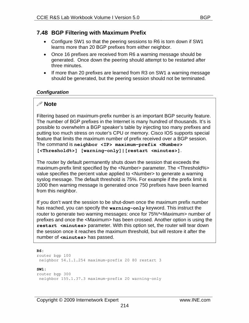
CCIE R&S Lab Workbook Volume I Version 5.0 BGP
Copyright © 2009 Internetwork Expert www.INE.com214
7.48 BGP Filtering with Maximum Prefix • Configure SW1 so that the peering sessions to R6 is torn down if SW1
learns more than 20 BGP prefixes from either neighbor. • Once 16 prefixes are received from R6 a warning message should be
generated. Once down the peering should attempt to be restarted after three minutes.
• If more than 20 prefixes are learned from R3 on SW1 a warning message should be generated, but the peering session should not be terminated.
Configuration
Note
Filtering based on maximum-prefix number is an important BGP security feature. The number of BGP prefixes in the Internet is many hundred of thousands. It’s is possible to overwhelm a BGP speaker’s table by injecting too many prefixes and putting too much stress on router’s CPU or memory. Cisco IOS supports special feature that limits the maximum number of prefix received over a BGP session. The command is neighbor <IP> maximum-prefix <Number> [<Threshold%>] [warning-only]|[restart <minutes>].
The router by default permanently shuts down the session that exceeds the maximum-prefix limit specified by the <Number> parameter. The <Threshold%> value specifies the percent value applied to <Number> to generate a warning syslog message. The default threshold is 75%. For example if the prefix limit is 1000 then warning message is generated once 750 prefixes have been learned from this neighbor.
If you don’t want the session to be shut-down once the maximum prefix number has reached, you can specify the warning-only keyword. This instruct the router to generate two warning messages: once for 75%*<Maximum> number of prefixes and once the <Maximum> has been crossed. Another option is using the restart <minutes> parameter. With this option set, the router will tear down the session once it reaches the maximum threshold, but will restore it after the number of <minutes> has passed.
R6: router bgp 100 neighbor 54.1.1.254 maximum-prefix 20 80 restart 3
SW1: router bgp 300 neighbor 155.1.37.3 maximum-prefix 20 warning-only
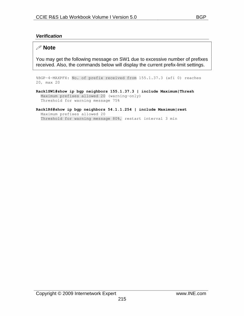
CCIE R&S Lab Workbook Volume I Version 5.0 BGP
Copyright © 2009 Internetwork Expert www.INE.com215
Verification
Note
You may get the following message on SW1 due to excessive number of prefixes received. Also, the commands below will display the current prefix-limit settings.
%BGP-4-MAXPFX: No. of prefix received from 155.1.37.3 (afi 0) reaches 20, max 20
Rack1SW1#show ip bgp neighbors 155.1.37.3 | include Maximum|Thresh Maximum prefixes allowed 20 (warning-only) Threshold for warning message 75%
Rack1R6#show ip bgp neighbors 54.1.1.254 | include Maximum|rest Maximum prefixes allowed 20 Threshold for warning message 80%, restart interval 3 min
CCIE R&S Lab Workbook Volume I Version 5.0 BGP
Copyright © 2009 Internetwork Expert www.INE.com216
7.49 BGP Default Routing • Configure R2 to originate a default route to R3 and R5 via BGP. • This default route should be withdrawn if R2's link to BB2 goes down.
Configuration
Note
BGP default routing could be helpful when a stub AS uses just one uplink or uses primary-backup uplinks scenario. The upstream eBGP peers could be configure to advertise just the default route information. You may inject a default route into BGP by using the network 0.0.0.0 mask 0.0.0.0 command, provided that there is a default route in the RIB. However, this will advertise the default route to all BGP neighbors. To selectively generate a default route, use the command neighbor <IP> default-originate [route-map <CONDITION>]. Without the route-map parameter, this command will generate a default route and send it to the configured peer. It is not required to have a matching default route in the BGP table or the RIB.
You can make the default-route advertisement conditional by associating a route-map with the statement. In this case, the default route is advertised if the route-map match conditions are satisfied. You can match ip addresses with the route-map using either standard, extended access-list or prefix-lists. When using extended ACLs, you can match both the prefix and the subnet mask range in the same way you specify that for BGP filtering. In our scenario, we are required to advertise the default route only if the interface connecting R2 to BB2 is up. This is accomplished by matching the prefix corresponding to the interface subnet 192.10.X.0/24. For more advanced scenarios, you may create reliable static routes, tracking the next hop reachability and matching the reliable prefix within the conditional route-map.
R2: ip prefix-list LINK_TO_BB2 permit 192.10.1.0/24 ! route-map DEFAULT permit 10 match ip address prefix-list LINK_TO_BB2 ! router bgp 200 neighbor 155.1.23.3 default-originate route-map DEFAULT neighbor 155.1.0.5 default-originate route-map DEFAULT
CCIE R&S Lab Workbook Volume I Version 5.0 BGP
Copyright © 2009 Internetwork Expert www.INE.com217
Verification
Note
Make sure both R3 and R5 receive the default route from R2
Rack1R3#show ip bgp 0.0.0.0 BGP routing table entry for 0.0.0.0/0, version 30 Paths: (2 available, best #2, table Default-IP-Routing-Table) Advertised to update-groups: 1 2 3 Local 155.1.0.2 from 155.1.0.5 (150.1.5.5) Origin IGP, metric 0, localpref 100, valid, internal Originator: 150.1.2.2, Cluster list: 150.1.5.5 Local, (Received from a RR-client) 155.1.23.2 from 155.1.23.2 (150.1.2.2) Origin IGP, metric 0, localpref 100, valid, internal, best
Rack1R5#show ip bgp 0.0.0.0 BGP routing table entry for 0.0.0.0/0, version 41 Paths: (2 available, best #2, table Default-IP-Routing-Table) Advertised to update-groups: 1 2 3 Local 155.1.23.2 (metric 2681856) from 155.1.23.3 (150.1.3.3) Origin IGP, metric 0, localpref 100, valid, internal Originator: 150.1.2.2, Cluster list: 150.1.3.3 Local, (Received from a RR-client) 155.1.0.2 from 155.1.0.2 (150.1.2.2) Origin IGP, metric 0, localpref 100, valid, internal, best
Note
Now configure R2 to debug BGP updates for the prefix 0.0.0.0. Shut down the interface connected to BB2 and observe how R2 sends BGP WITHDRAW messages to R3 and R5.
Rack1R2(config)#access-list 99 permit 0.0.0.0 Rack1R2#debug ip bgp updates 99 BGP updates debugging is on for access list 99 for address family: IPv4 Unicast Rack1R2#conf t Enter configuration commands, one per line. End with CNTL/Z. Rack1R2(config)#interface fastEthernet 0/0 Rack1R2(config-if)#shutdown Rack1R2# %BGP-5-ADJCHANGE: neighbor 192.10.1.254 Down Interface flap BGP(0): 155.1.0.5 send unreachable 0.0.0.0/0 BGP(0): 155.1.0.5 enqueued default-originate update BGP(0): 155.1.23.3 send unreachable 0.0.0.0/0 BGP(0): 155.1.23.3 enqueued default-originate update
CCIE R&S Lab Workbook Volume I Version 5.0 BGP
Copyright © 2009 Internetwork Expert www.INE.com218
7.50 BGP Local AS • AS 100 is planning transition to the AS number 146. Configure R4 and R6
and to use the new AS number while R1 should still use the old AS 100. • Ensure all BGP peering relationships are still maintained but do not modify
the configurations of any routers with except to R1, R4 and R6.
Configuration
Note
The Hide Local Autonomous System feature could be useful when migrating an autonomous system to a different AS number. When the AS has multiple eBGP peering links, it may become time consuming to negotiate the AS number change with all peering partners. In this case, you may reconfigure the local BGP speakers to use the new AS number but advertise the old AS in BGP OPEN messages and BGP updates. This could be enforced on per-eBGP peer basis using the command neighbor <IP> local-as <OldAS> [no-prepend].
The local-as <OldAS> command instructs the local router to advertise the <OldAS> number in BGP OPEN messages instead of the AS number specified with router bgp <NewAS> command. In addition to that, all BGP prefixes advertised to this eBGP peer would have the AS numbers <OldAS> <NewAS> preprended in front of every BGP update’s AS_PATH attribute. Thus, the external system may continue with the local system using the old AS number. In addition to that, the external system will see the updates coming from the <OldAS> looking like they first transited <NewAS>. This is needed to avoid BGP routing loops.
If you specify the no-prepend keyword, then any routes received from the eBGP peer will not have <OldAS> prepended upon reception. By default the AS number specified with the local-as command (<OldAS>) is prepended to all updates received, to avoid potential routing loops. However, this may cause problems with partial transitions, when part of your AS is using the new AS number, and another part is still using the old AS number. The routers using the old number will reject such updates due to the same AS number present in AS_PATH.
In our scenario, only R4 and R6 have been reconfigured to use the new AS number 146. R1 is still using AS 100 and have been reconfigured to peer eBGP with R4 and R6. In order to make R1 accept AS 54 prefixes, we use the no-prepend keyword when peering using the local-as feature with BB1 and BB3.
CCIE R&S Lab Workbook Volume I Version 5.0 BGP
Copyright © 2009 Internetwork Expert www.INE.com219
R1: router bgp 100 no neighbor 155.1.146.4 route-reflector-client no neighbor 155.1.146.6 route-reflector-client neighbor 155.1.146.4 remote-as 146 neighbor 155.1.146.6 remote-as 146 neighbor 155.1.13.3 remote-as 200
R4: no router bgp 100 router bgp 146 neighbor 155.1.146.1 remote-as 100 neighbor 204.12.1.254 remote-as 54 neighbor 204.12.1.254 local-as 100 no-prepend neighbor 155.1.45.5 remote-as 200 neighbor 155.1.45.5 local-as 100 no-prepend network 155.1.146.0 mask 255.255.255.0 aggregate-address 155.1.0.0 255.255.0.0 summary-only
R6: no router bgp 100 router bgp 146 neighbor 155.1.146.1 remote-as 100 neighbor 54.1.1.254 remote-as 54 neighbor 54.1.1.254 local-as 100 no-prepend neighbor 155.1.67.7 remote-as 300 neighbor 155.1.67.7 local-as 100 no-prepend network 155.1.146.0 mask 255.255.255.0 aggregate-address 155.1.0.0 255.255.0.0 summary-only
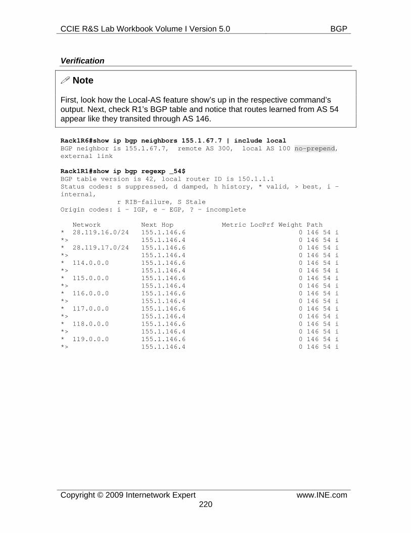
CCIE R&S Lab Workbook Volume I Version 5.0 BGP
Copyright © 2009 Internetwork Expert www.INE.com220
Verification
Note
First, look how the Local-AS feature show’s up in the respective command’s output. Next, check R1’s BGP table and notice that routes learned from AS 54 appear like they transited through AS 146.
Rack1R6#show ip bgp neighbors 155.1.67.7 | include local BGP neighbor is 155.1.67.7, remote AS 300, local AS 100 no-prepend, external link
Rack1R1#show ip bgp regexp _54$ BGP table version is 42, local router ID is 150.1.1.1 Status codes: s suppressed, d damped, h history, * valid, > best, i - internal, r RIB-failure, S Stale Origin codes: i - IGP, e - EGP, ? - incomplete
Network Next Hop Metric LocPrf Weight Path * 28.119.16.0/24 155.1.146.6 0 146 54 i *> 155.1.146.4 0 146 54 i * 28.119.17.0/24 155.1.146.6 0 146 54 i *> 155.1.146.4 0 146 54 i * 114.0.0.0 155.1.146.6 0 146 54 i *> 155.1.146.4 0 146 54 i * 115.0.0.0 155.1.146.6 0 146 54 i *> 155.1.146.4 0 146 54 i * 116.0.0.0 155.1.146.6 0 146 54 i *> 155.1.146.4 0 146 54 i * 117.0.0.0 155.1.146.6 0 146 54 i *> 155.1.146.4 0 146 54 i * 118.0.0.0 155.1.146.6 0 146 54 i *> 155.1.146.4 0 146 54 i * 119.0.0.0 155.1.146.6 0 146 54 i *> 155.1.146.4 0 146 54 i
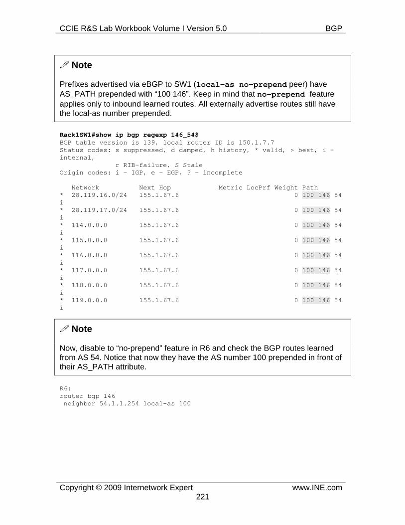
CCIE R&S Lab Workbook Volume I Version 5.0 BGP
Copyright © 2009 Internetwork Expert www.INE.com221
Note
Prefixes advertised via eBGP to SW1 (local-as no-prepend peer) have AS_PATH prepended with “100 146”. Keep in mind that no-prepend feature applies only to inbound learned routes. All externally advertise routes still have the local-as number prepended.
Rack1SW1#show ip bgp regexp 146_54$ BGP table version is 139, local router ID is 150.1.7.7 Status codes: s suppressed, d damped, h history, * valid, > best, i - internal, r RIB-failure, S Stale Origin codes: i - IGP, e - EGP, ? - incomplete
Network Next Hop Metric LocPrf Weight Path * 28.119.16.0/24 155.1.67.6 0 100 146 54 i * 28.119.17.0/24 155.1.67.6 0 100 146 54 i * 114.0.0.0 155.1.67.6 0 100 146 54 i * 115.0.0.0 155.1.67.6 0 100 146 54 i * 116.0.0.0 155.1.67.6 0 100 146 54 i * 117.0.0.0 155.1.67.6 0 100 146 54 i * 118.0.0.0 155.1.67.6 0 100 146 54 i * 119.0.0.0 155.1.67.6 0 100 146 54 i
Note
Now, disable to “no-prepend” feature in R6 and check the BGP routes learned from AS 54. Notice that now they have the AS number 100 prepended in front of their AS_PATH attribute.
R6: router bgp 146 neighbor 54.1.1.254 local-as 100
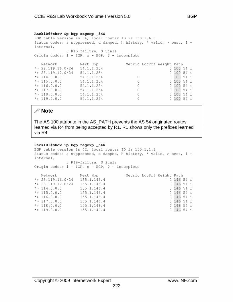
CCIE R&S Lab Workbook Volume I Version 5.0 BGP
Copyright © 2009 Internetwork Expert www.INE.com222
Rack1R6#show ip bgp regexp _54$ BGP table version is 34, local router ID is 150.1.6.6 Status codes: s suppressed, d damped, h history, * valid, > best, i - internal, r RIB-failure, S Stale Origin codes: i - IGP, e - EGP, ? - incomplete
Network Next Hop Metric LocPrf Weight Path *> 28.119.16.0/24 54.1.1.254 0 100 54 i *> 28.119.17.0/24 54.1.1.254 0 100 54 i *> 114.0.0.0 54.1.1.254 0 0 100 54 i *> 115.0.0.0 54.1.1.254 0 0 100 54 i *> 116.0.0.0 54.1.1.254 0 0 100 54 i *> 117.0.0.0 54.1.1.254 0 0 100 54 i *> 118.0.0.0 54.1.1.254 0 0 100 54 i *> 119.0.0.0 54.1.1.254 0 0 100 54 i
Note
The AS 100 attribute in the AS_PATH prevents the AS 54 originated routes learned via R4 from being accepted by R1. R1 shows only the prefixes learned via R4.
Rack1R1#show ip bgp regexp _54$ BGP table version is 42, local router ID is 150.1.1.1 Status codes: s suppressed, d damped, h history, * valid, > best, i - internal, r RIB-failure, S Stale Origin codes: i - IGP, e - EGP, ? - incomplete
Network Next Hop Metric LocPrf Weight Path *> 28.119.16.0/24 155.1.146.4 0 146 54 i *> 28.119.17.0/24 155.1.146.4 0 146 54 i *> 114.0.0.0 155.1.146.4 0 146 54 i *> 115.0.0.0 155.1.146.4 0 146 54 i *> 116.0.0.0 155.1.146.4 0 146 54 i *> 117.0.0.0 155.1.146.4 0 146 54 i *> 118.0.0.0 155.1.146.4 0 146 54 i *> 119.0.0.0 155.1.146.4 0 146 54 i
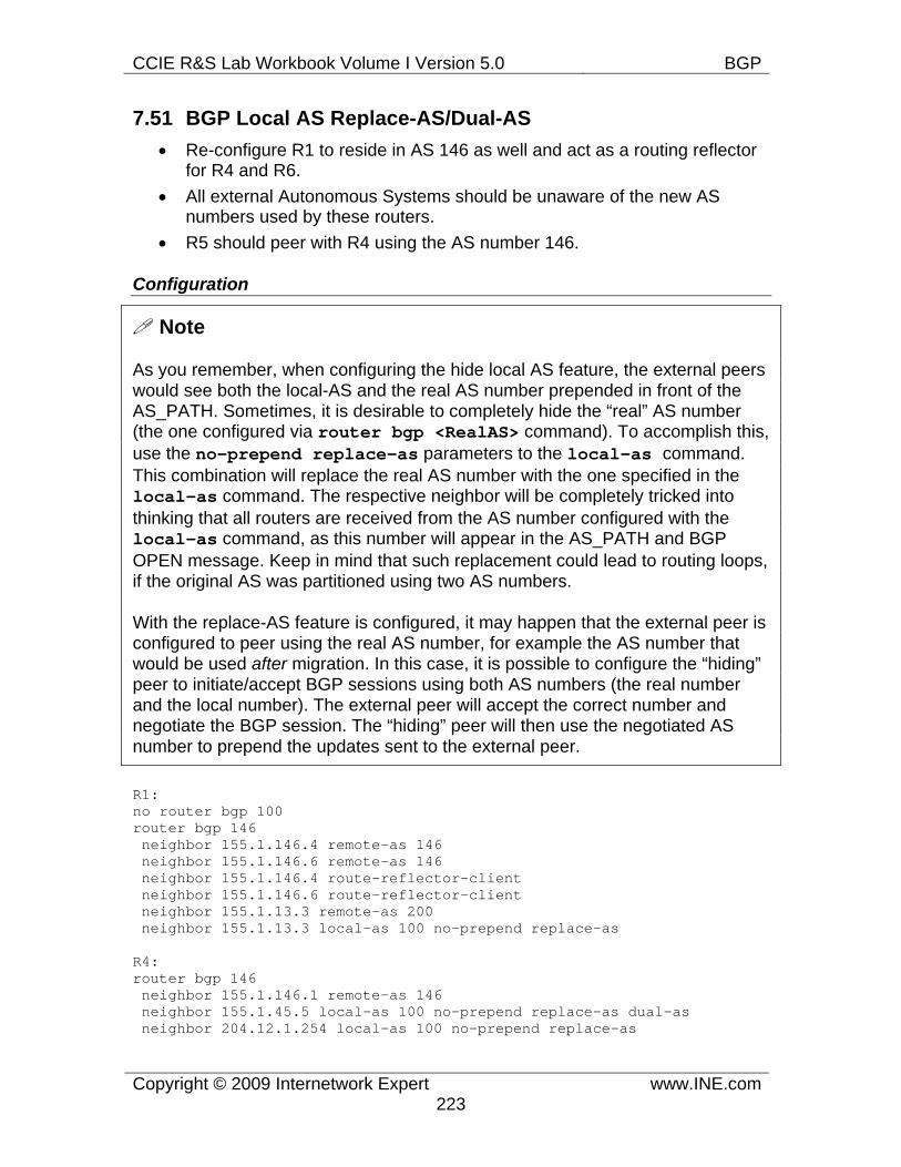
CCIE R&S Lab Workbook Volume I Version 5.0 BGP
Copyright © 2009 Internetwork Expert www.INE.com223
7.51 BGP Local AS Replace-AS/Dual-AS • Re-configure R1 to reside in AS 146 as well and act as a routing reflector
for R4 and R6. • All external Autonomous Systems should be unaware of the new AS
numbers used by these routers. • R5 should peer with R4 using the AS number 146.
Configuration
Note
As you remember, when configuring the hide local AS feature, the external peers would see both the local-AS and the real AS number prepended in front of the AS_PATH. Sometimes, it is desirable to completely hide the “real” AS number (the one configured via router bgp <RealAS> command). To accomplish this, use the no-prepend replace-as parameters to the local-as command. This combination will replace the real AS number with the one specified in the local-as command. The respective neighbor will be completely tricked into thinking that all routers are received from the AS number configured with the local-as command, as this number will appear in the AS_PATH and BGP OPEN message. Keep in mind that such replacement could lead to routing loops, if the original AS was partitioned using two AS numbers.
With the replace-AS feature is configured, it may happen that the external peer is configured to peer using the real AS number, for example the AS number that would be used after migration. In this case, it is possible to configure the “hiding” peer to initiate/accept BGP sessions using both AS numbers (the real number and the local number). The external peer will accept the correct number and negotiate the BGP session. The “hiding” peer will then use the negotiated AS number to prepend the updates sent to the external peer.
R1: no router bgp 100 router bgp 146 neighbor 155.1.146.4 remote-as 146 neighbor 155.1.146.6 remote-as 146 neighbor 155.1.146.4 route-reflector-client neighbor 155.1.146.6 route-reflector-client neighbor 155.1.13.3 remote-as 200 neighbor 155.1.13.3 local-as 100 no-prepend replace-as
R4: router bgp 146 neighbor 155.1.146.1 remote-as 146 neighbor 155.1.45.5 local-as 100 no-prepend replace-as dual-as neighbor 204.12.1.254 local-as 100 no-prepend replace-as
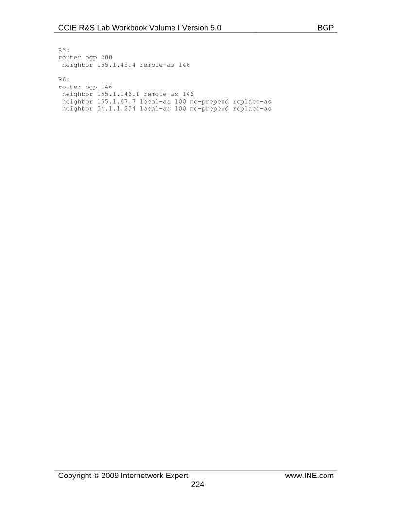
CCIE R&S Lab Workbook Volume I Version 5.0 BGP
Copyright © 2009 Internetwork Expert www.INE.com224
R5: router bgp 200 neighbor 155.1.45.4 remote-as 146
R6: router bgp 146 neighbor 155.1.146.1 remote-as 146 neighbor 155.1.67.7 local-as 100 no-prepend replace-as neighbor 54.1.1.254 local-as 100 no-prepend replace-as
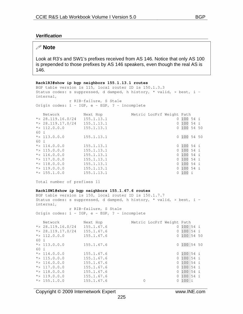
CCIE R&S Lab Workbook Volume I Version 5.0 BGP
Copyright © 2009 Internetwork Expert www.INE.com225
Verification
Note
Look at R3’s and SW1’s prefixes received from AS 146. Notice that only AS 100 is prepended to those prefixes by AS 146 speakers, even though the real AS is 146.
Rack1R3#show ip bgp neighbors 155.1.13.1 routes BGP table version is 115, local router ID is 150.1.3.3 Status codes: s suppressed, d damped, h history, * valid, > best, i - internal, r RIB-failure, S Stale Origin codes: i - IGP, e - EGP, ? - incomplete
Network Next Hop Metric LocPrf Weight Path *> 28.119.16.0/24 155.1.13.1 0 100 54 i *> 28.119.17.0/24 155.1.13.1 0 100 54 i *> 112.0.0.0 155.1.13.1 0 100 54 50 60 i *> 113.0.0.0 155.1.13.1 0 100 54 50 60 i *> 114.0.0.0 155.1.13.1 0 100 54 i *> 115.0.0.0 155.1.13.1 0 100 54 i *> 116.0.0.0 155.1.13.1 0 100 54 i *> 117.0.0.0 155.1.13.1 0 100 54 i *> 118.0.0.0 155.1.13.1 0 100 54 i *> 119.0.0.0 155.1.13.1 0 100 54 i *> 155.1.0.0 155.1.13.1 0 100 i
Total number of prefixes 11
Rack1SW1#show ip bgp neighbors 155.1.67.6 routes BGP table version is 150, local router ID is 150.1.7.7 Status codes: s suppressed, d damped, h history, * valid, > best, i - internal, r RIB-failure, S Stale Origin codes: i - IGP, e - EGP, ? - incomplete
Network Next Hop Metric LocPrf Weight Path *> 28.119.16.0/24 155.1.67.6 0 100 54 i *> 28.119.17.0/24 155.1.67.6 0 100 54 i *> 112.0.0.0 155.1.67.6 0 100 54 50 60 i *> 113.0.0.0 155.1.67.6 0 100 54 50 60 i *> 114.0.0.0 155.1.67.6 0 100 54 i *> 115.0.0.0 155.1.67.6 0 100 54 i *> 116.0.0.0 155.1.67.6 0 100 54 i *> 117.0.0.0 155.1.67.6 0 100 54 i *> 118.0.0.0 155.1.67.6 0 100 54 i *> 119.0.0.0 155.1.67.6 0 100 54 i *> 155.1.0.0 155.1.67.6 0 0 100 i
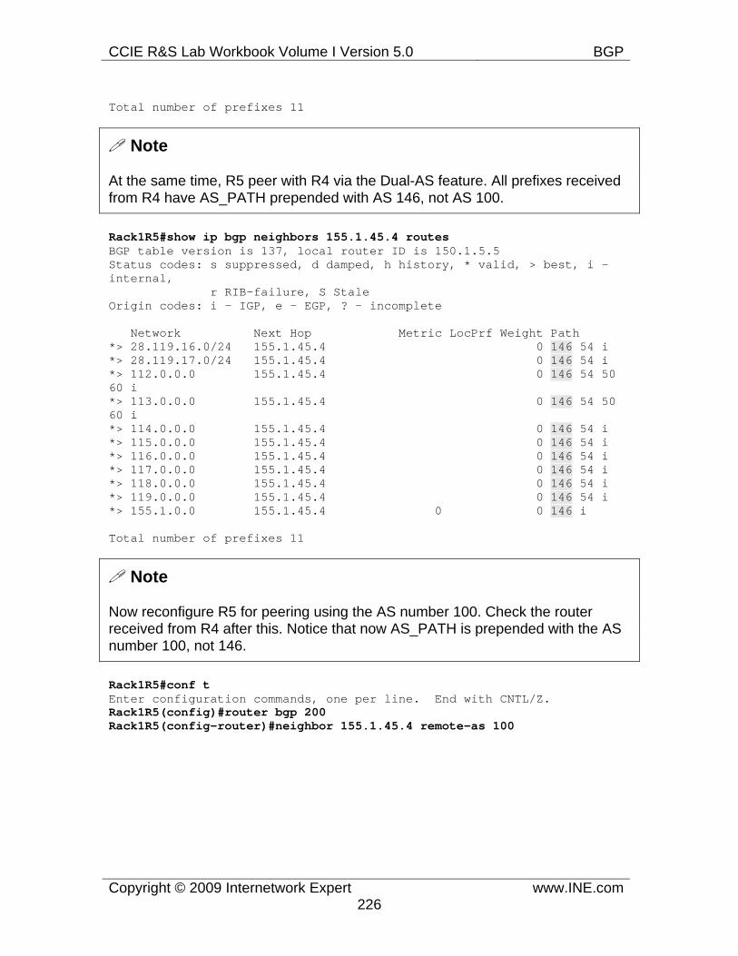
CCIE R&S Lab Workbook Volume I Version 5.0 BGP
Copyright © 2009 Internetwork Expert www.INE.com226
Total number of prefixes 11
Note
At the same time, R5 peer with R4 via the Dual-AS feature. All prefixes received from R4 have AS_PATH prepended with AS 146, not AS 100.
Rack1R5#show ip bgp neighbors 155.1.45.4 routes BGP table version is 137, local router ID is 150.1.5.5 Status codes: s suppressed, d damped, h history, * valid, > best, i - internal, r RIB-failure, S Stale Origin codes: i - IGP, e - EGP, ? - incomplete
Network Next Hop Metric LocPrf Weight Path *> 28.119.16.0/24 155.1.45.4 0 146 54 i *> 28.119.17.0/24 155.1.45.4 0 146 54 i *> 112.0.0.0 155.1.45.4 0 146 54 50 60 i *> 113.0.0.0 155.1.45.4 0 146 54 50 60 i *> 114.0.0.0 155.1.45.4 0 146 54 i *> 115.0.0.0 155.1.45.4 0 146 54 i *> 116.0.0.0 155.1.45.4 0 146 54 i *> 117.0.0.0 155.1.45.4 0 146 54 i *> 118.0.0.0 155.1.45.4 0 146 54 i *> 119.0.0.0 155.1.45.4 0 146 54 i *> 155.1.0.0 155.1.45.4 0 0 146 i
Total number of prefixes 11
Note
Now reconfigure R5 for peering using the AS number 100. Check the router received from R4 after this. Notice that now AS_PATH is prepended with the AS number 100, not 146.
Rack1R5#conf t Enter configuration commands, one per line. End with CNTL/Z. Rack1R5(config)#router bgp 200 Rack1R5(config-router)#neighbor 155.1.45.4 remote-as 100
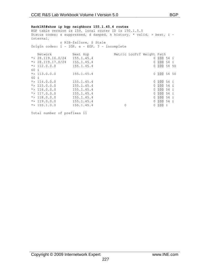
CCIE R&S Lab Workbook Volume I Version 5.0 BGP
Copyright © 2009 Internetwork Expert www.INE.com227
Rack1R5#show ip bgp neighbors 155.1.45.4 routes BGP table version is 159, local router ID is 150.1.5.5 Status codes: s suppressed, d damped, h history, * valid, > best, i - internal, r RIB-failure, S Stale Origin codes: i - IGP, e - EGP, ? - incomplete
Network Next Hop Metric LocPrf Weight Path *> 28.119.16.0/24 155.1.45.4 0 100 54 i *> 28.119.17.0/24 155.1.45.4 0 100 54 i *> 112.0.0.0 155.1.45.4 0 100 54 50 60 i *> 113.0.0.0 155.1.45.4 0 100 54 50 60 i *> 114.0.0.0 155.1.45.4 0 100 54 i *> 115.0.0.0 155.1.45.4 0 100 54 i *> 116.0.0.0 155.1.45.4 0 100 54 i *> 117.0.0.0 155.1.45.4 0 100 54 i *> 118.0.0.0 155.1.45.4 0 100 54 i *> 119.0.0.0 155.1.45.4 0 100 54 i *> 155.1.0.0 155.1.45.4 0 0 100 i
Total number of prefixes 11
CCIE R&S Lab Workbook Volume I Version 5.0 BGP
Copyright © 2009 Internetwork Expert www.INE.com228
7.52 BGP Remove Private AS • Reconfigure SW1 and SW3 in the private AS 65089 and adjust the
peering settings accordingly. • Create and advertise Loopback subnet in SW1 with the IP address
7.7.7.7/24. • Configure AS 100 and AS 200 speakers to strip the private AS number
when advertising the prefixes to AS 254 and AS 54.
Configuration
Note
Private AS numbers in range 64512-65535 are often assigned to small enterprises that use BGP to peer with their ISPs. Private AS numbers are similar to RFC 1918 IP addressing, which allows for consuming AS numbers on the Internet. However, private AS numbers should not appear on the public Internet, as many sites may originate the same number. Thus, the AS that provides upstream connection for the private site should remove the private AS numbers from the AS_PATH attribute.
The command to perform the AS_PATH stripping in IOS is neighbor <IP> remove-private-as. All BGP updates sent over this session are inspected to have a sequence of private AS numbers in the beginning of the AS_PATH. All private numbers are then removed and the local AS number is prepended. Notice that in situation when the private AS sequence is not located in the beginning of the AS_PATH, the stripping will not work and AS_PATH will remain unmodified.
R2: router bgp 200 neighbor 192.10.1.254 remove-private-as
R3: router bgp 200 neighbor 155.1.37.7 remote-as 65089
R4: router bgp 146 neighbor 204.12.1.254 remove-private-as
R6: ! ! BGP AS was modified in the previous task ! router bgp 146 neighbor 155.1.67.7 remote-as 65089 neighbor 54.1.1.254 remove-private-as
SW1:
CCIE R&S Lab Workbook Volume I Version 5.0 BGP
Copyright © 2009 Internetwork Expert www.INE.com229
no router bgp 300 router bgp 65089 neighbor 155.1.79.9 remote-as 65089 neighbor 155.1.67.6 remote-as 100 neighbor 155.1.37.3 remote-as 200 network 7.7.7.0 mask 255.255.255.0 ! interface Loopback1 ip address 7.7.7.7 255.255.255.0
SW3: no router bgp 300 router bgp 65089 neighbor 155.1.79.7 remote-as 65089
CCIE R&S Lab Workbook Volume I Version 5.0 BGP
Copyright © 2009 Internetwork Expert www.INE.com230
Verification
Note
First, check the paths advertised to BB3 on R4. Notice the AS_PATH attribute for the prefix 7.7.7.0/24. This is the output of Adj-RIBs-Out, and the result of the private AS removal and local AS prepending is not yet show.
Rack1R4#show ip bgp neighbors 204.12.1.254 advertised-routes BGP table version is 22, local router ID is 150.1.4.4 Status codes: s suppressed, d damped, h history, * valid, > best, i - internal, r RIB-failure, S Stale Origin codes: i - IGP, e - EGP, ? - incomplete
Network Next Hop Metric LocPrf Weight Path *>i7.7.7.0/24 155.1.67.7 0 100 0 65089 i *> 155.1.0.0 0.0.0.0 32768 i *> 205.90.31.0 155.1.45.5 0 200 254 ? *> 220.20.3.0 155.1.45.5 0 200 254 ? *> 222.22.2.0 155.1.45.5 0 200 254 ?
Note
Now check BB3’s BGP table. Notice that the prefixy 7.7.7.0/24 appear with the AS_PATH of 100, i.e. the private number has been removed. Keep in mind that in the real exam you wont have access to the backbone routers.
RS.30.1.BB3>show ip bgp BGP table version is 16, local router ID is 31.3.0.1 Status codes: s suppressed, d damped, h history, * valid, > best, i - internal, r RIB-failure, S Stale Origin codes: i - IGP, e - EGP, ? - incomplete
Network Next Hop Metric LocPrf Weight Path * i7.7.7.0/24 172.16.4.1 0 100 0 100 i *> 204.12.1.4 0 100 i *> 28.119.16.0/24 0.0.0.0 0 32768 i *> 28.119.17.0/24 0.0.0.0 0 32768 i *>i112.0.0.0 172.16.4.1 0 100 0 i
CCIE R&S Lab Workbook Volume I Version 5.0 BGP
Copyright © 2009 Internetwork Expert www.INE.com231
Note
Now shut down the BGP peering session between R6 and SW1. This will make AS 100 (146) accept the prefix from AS 200 with the AS_PATH “200 65089”. Notice that in real life AS 200 should have removed the private AS when advertising the prefix to AS 100. However, we intentionally left this misconfiguration.
R6: neighbor 155.1.67.7 shutdown
Rack1R4#show ip bgp neighbors 204.12.1.254 advertised-routes BGP table version is 24, local router ID is 150.1.4.4 Status codes: s suppressed, d damped, h history, * valid, > best, i - internal, r RIB-failure, S Stale Origin codes: i - IGP, e - EGP, ? - incomplete
Network Next Hop Metric LocPrf Weight Path *> 7.7.7.0/24 155.1.45.5 0 200 65089 i *> 155.1.0.0 0.0.0.0 32768 i *> 205.90.31.0 155.1.45.5 0 200 254 ? *> 220.20.3.0 155.1.45.5 0 200 254 ? *> 222.22.2.0 155.1.45.5 0 200 254 ?
Total number of prefixes 5
Note
Now check BB3’s BGP table and notice that the private AS has not been stripped, as it wasn’t the first AS number in the AS_PATH.
RS.30.1.BB3>show ip bgp BGP table version is 18, local router ID is 31.3.0.1 Status codes: s suppressed, d damped, h history, * valid, > best, i - internal, r RIB-failure, S Stale Origin codes: i - IGP, e - EGP, ? - incomplete
Network Next Hop Metric LocPrf Weight Path * i7.7.7.0/24 172.16.4.1 0 100 0 100 200 65089 i *> 204.12.1.4 0 100 200 65089 i
CCIE R&S Lab Workbook Volume I Version 5.0 BGP
Copyright © 2009 Internetwork Expert www.INE.com232
7.53 BGP Dampening • Create Looback1 interface in R1 with the IP address 1.1.1.1/24 and
advertise it into BGP. • Configure AS 200 routers to suppress advertisement of oscillating
networks. • Once a prefix flaps two times in a row, the advertisement should resume
in 5 minutes.
Configuration
Note
Network instabilities (e.g. unreliable links) may cause BGP prefix flapping. A flap is the even of a network prefix going up and down or vice-versa, i.e. flap is change in reachability state. Prefix flapping is dangerous to network stability, as it causes network withdraws and best-path re-computations. Moreover, a flapping prefix may cause recursive route withdrawn, resulting in massive BGP table changes. Two main methods to reduce the impact of network instabilities are summarization (information hiding) and prefix dampening. Summarization aggregates reachability information and hides flaps of the specific prefixes constituting a summary. Dampening is the process of suppressing a flapping prefix advertisement till the moment it becomes “stable”. This introduces some “inertial” mechanism to new prefix advertisement, delaying the changes announcements for oscillating prefixes.
The idea of dampening is to suppress a prefix based on the number of flaps accounted and un-suppress the prefix only after an exponentially decaying timer expired. Here is the description of the process. Every time a prefix flaps, it is assigned an additive penalty value, 1000 by default. If this is just an attribute change, e.g. Local-Preference or AS_PATH then the penalty is halved, i.e. 500 by default. If the prefix becomes unavailable after flapping at least once, BGP process still keeps it in the table, marked in “history” state to account for further flaps and penalty accumulation. If the accumulated penalty value exceeds the Suppress Limit, which defaults to 2000, BGP process will mark the route as damped. Even though the prefix could be currently “active” (flapped from down to up), BGP will not advertise it to any peers. Every five seconds the BGP process exponentially decreases the penalty value assigned to the prefix. The exponential decay process has one parameter - Half-Life time period, which specifies the amount of time needed to decrease the current penalty to the value twice smaller. That is, the decay process follows the equation P(t) = P(0)/2^(t/Half_Life) with the default Half_Life time of 15 minutes. As soon as the penalty falls below the Reuse Limit, the router will unsuppress the route and start advertising it again. The decision to unsuppress a prefix is made every 10 seconds.
CCIE R&S Lab Workbook Volume I Version 5.0 BGP
Copyright © 2009 Internetwork Expert www.INE.com233
When facing tasks similar to the current scenario, you should understand that they assume some “ideal” conditions. That is, when the scenario says “flaps two times in a row” you may assume the flaps immediately once after another. This results in accumulated penalty of 2000 and route being damped. We now need to find the Half_Life value that will make the router reuse the prefix in 5 minutes. We take the penalty evolution equation and write it as follows:
P(5) = P(0)/2^(5/Half_Life)
And substitute P(5)=750 (the reuse limit) and P(0)=2000 (Suppress Limit). The equation then becomes:
200/750=2^(5/Half_Life)
From this equation we can find the Half_Life value by taking logarithm of the both sides:
Half_Life=5*Ln(2)/Ln(200/75)=3.5 (approximately).
We may round the result up to 4 minutes. That is, the task could be accomplished by setting the Half_Life value to 4 minutes. Now, the BGP command to apply the dampening parameters is bgp dampening [<Half_Life> <ReuseLimit> <SuppressLimit> <MaximumSuppressTime>]. The last parameter, <MaximumSuppressTime>, specifies the time limit to keep the prefix damped if it keeps oscillating. The default value if 4xHalf_Life or 60 minutes. The router sets the maximum penalty value based on this timer using the formula Max_Penalty = ReuseLimit *2^(MaximumSuppressTime/Half_Life). You may review the current dampening parameters (if enabled) using the command show ip bgp dampening parameters.
R2, R3, R5, SW2, SW4:router bgp 200 bgp dampening 4 750 2000 16
R1: ! ! We adjust the advertisement interval to minimize prefix batching ! and make R1 advertise prefix changes ASAP ! router bgp 146 network 1.1.1.0 mask 255.255.255.0 neighbor 155.1.13.3 advertisement-interval 0 ! interface Loopback1 ip address 1.1.1.1 255.255.255.0
CCIE R&S Lab Workbook Volume I Version 5.0 BGP
Copyright © 2009 Internetwork Expert www.INE.com234
Verification
Note
Start by checking the BGP dampening parameters in any of AS 200 routers. Next, go to R1 and shutdown/no shutdown Loopback1 interface a few times emulating route flaps, enough to accumulate the suppress-limit penalty in AS 200 routers.
Rack1R3#show ip bgp dampening parameters dampening 4 750 2000 16 Half-life time : 4 mins Decay Time : 620 secs Max suppress penalty: 12000 Max suppress time: 16 mins Suppress penalty : 2000 Reuse penalty : 750
Note
Inspect dampened path and flap statistics in R3. Notice the character “d” meaning the prefixes have been damped.
Rack1R3#show ip bgp dampening dampened-paths BGP table version is 31, local router ID is 150.1.3.3 Status codes: s suppressed, d damped, h history, * valid, > best, i - internal, r RIB-failure, S Stale Origin codes: i - IGP, e - EGP, ? - incomplete
Network From Reuse Path *d 1.1.1.0/24 155.1.13.1 00:09:20 100 i d 1.1.1.0/24 155.1.37.7 00:07:00 300 100 i
Rack1R3#show ip bgp dampening flap-statistics BGP table version is 31, local router ID is 150.1.3.3 Status codes: s suppressed, d damped, h history, * valid, > best, i - internal, r RIB-failure, S Stale Origin codes: i - IGP, e - EGP, ? - incomplete
Network From Flaps Duration Reuse Path *d 1.1.1.0/24 155.1.13.1 5 00:05:07 00:09:10 100 d 155.1.37.7 5 00:05:07 00:08:50 300 100
CCIE R&S Lab Workbook Volume I Version 5.0 BGP
Copyright © 2009 Internetwork Expert www.INE.com235
Note
Check R3’s BGP table for the prefix 1.1.1.0/24. Notice that the prefix shows up as damped and not advertised to any peer. If you check R2’s BGP table after this, you will notice that the prefix is not there.
Rack1R3#show ip bgp BGP table version is 31, local router ID is 150.1.3.3 Status codes: s suppressed, d damped, h history, * valid, > best, i - internal, r RIB-failure, S Stale Origin codes: i - IGP, e - EGP, ? - incomplete
Network Next Hop Metric LocPrf Weight Path *d 1.1.1.0/24 155.1.13.1 0 0 100 i *d 155.1.37.7 0 300 100 i
Rack1R3#show ip bgp 1.1.1.0 BGP routing table entry for 1.1.1.0/24, version 31 Paths: (2 available, no best path) Flag: 0x960 Not advertised to any peer 100, (suppressed due to dampening) 155.1.13.1 from 155.1.13.1 (150.1.1.1) Origin IGP, metric 0, localpref 100, valid, external Dampinfo: penalty 3542, flapped 5 times in 00:05:18, reuse in 00:09:00 300 100, (suppressed due to dampening) (history entry) 155.1.37.7 from 155.1.37.7 (150.1.7.7) Origin IGP, localpref 100, external Dampinfo: penalty 3330, flapped 5 times in 00:05:18, reuse in 00:08:40
Rack1R2#show ip bgp 1.1.1.0 % Network not in table
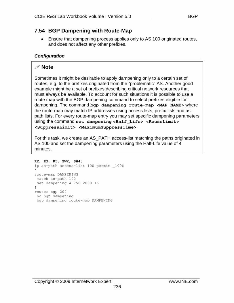
CCIE R&S Lab Workbook Volume I Version 5.0 BGP
Copyright © 2009 Internetwork Expert www.INE.com236
7.54 BGP Dampening with Route-Map • Ensure that dampening process applies only to AS 100 originated routes,
and does not affect any other prefixes.
Configuration
Note
Sometimes it might be desirable to apply dampening only to a certain set of routes, e.g. to the prefixes originated from the “problematic” AS. Another good example might be a set of prefixes describing critical network resources that must always be available. To account for such situations it is possible to use a route map with the BGP dampening command to select prefixes eligible for dampening. The command bgp dampening route-map <MAP_NAME> where the route-map may match IP addresses using access-lists, prefix-lists and as-path lists. For every route-map entry you may set specific dampening parameters using the command set dampening <Half_Life> <ReuseLimit> <SuppressLimit> <MaximumSuppressTime>.
For this task, we create an AS_PATH access-list matching the paths originated in AS 100 and set the dampening parameters using the Half-Life value of 4 minutes.
R2, R3, R5, SW2, SW4: ip as-path access-list 100 permit _100$ ! route-map DAMPENING match as-path 100 set dampening 4 750 2000 16 ! router bgp 200 no bgp dampening bgp dampening route-map DAMPENING
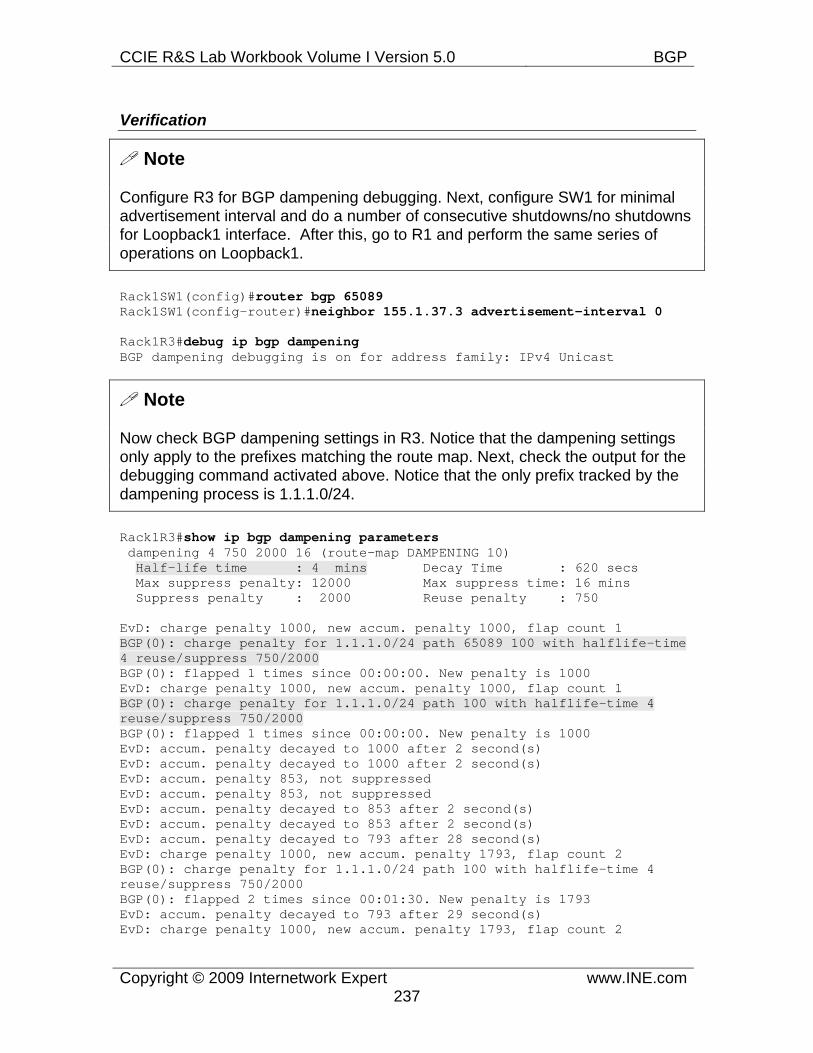
CCIE R&S Lab Workbook Volume I Version 5.0 BGP
Copyright © 2009 Internetwork Expert www.INE.com237
Verification
Note
Configure R3 for BGP dampening debugging. Next, configure SW1 for minimal advertisement interval and do a number of consecutive shutdowns/no shutdowns for Loopback1 interface. After this, go to R1 and perform the same series of operations on Loopback1.
Rack1SW1(config)#router bgp 65089Rack1SW1(config-router)#neighbor 155.1.37.3 advertisement-interval 0
Rack1R3#debug ip bgp dampening BGP dampening debugging is on for address family: IPv4 Unicast
Note
Now check BGP dampening settings in R3. Notice that the dampening settings only apply to the prefixes matching the route map. Next, check the output for the debugging command activated above. Notice that the only prefix tracked by the dampening process is 1.1.1.0/24.
Rack1R3#show ip bgp dampening parameters dampening 4 750 2000 16 (route-map DAMPENING 10) Half-life time : 4 mins Decay Time : 620 secs Max suppress penalty: 12000 Max suppress time: 16 mins Suppress penalty : 2000 Reuse penalty : 750
EvD: charge penalty 1000, new accum. penalty 1000, flap count 1 BGP(0): charge penalty for 1.1.1.0/24 path 65089 100 with halflife-time 4 reuse/suppress 750/2000 BGP(0): flapped 1 times since 00:00:00. New penalty is 1000 EvD: charge penalty 1000, new accum. penalty 1000, flap count 1 BGP(0): charge penalty for 1.1.1.0/24 path 100 with halflife-time 4 reuse/suppress 750/2000 BGP(0): flapped 1 times since 00:00:00. New penalty is 1000 EvD: accum. penalty decayed to 1000 after 2 second(s) EvD: accum. penalty decayed to 1000 after 2 second(s) EvD: accum. penalty 853, not suppressed EvD: accum. penalty 853, not suppressed EvD: accum. penalty decayed to 853 after 2 second(s) EvD: accum. penalty decayed to 853 after 2 second(s) EvD: accum. penalty decayed to 793 after 28 second(s) EvD: charge penalty 1000, new accum. penalty 1793, flap count 2 BGP(0): charge penalty for 1.1.1.0/24 path 100 with halflife-time 4 reuse/suppress 750/2000 BGP(0): flapped 2 times since 00:01:30. New penalty is 1793 EvD: accum. penalty decayed to 793 after 29 second(s) EvD: charge penalty 1000, new accum. penalty 1793, flap count 2

CCIE R&S Lab Workbook Volume I Version 5.0 BGP
Copyright © 2009 Internetwork Expert www.INE.com238
BGP(0): charge penalty for 1.1.1.0/24 path 65089 100 with halflife-time 4 reuse/suppress 750/2000 BGP(0): flapped 2 times since 00:01:31. New penalty is 1793 EvD: accum. penalty decayed to 1644 after 32 second(s) EvD: accum. penalty decayed to 1644 after 31 second(s)
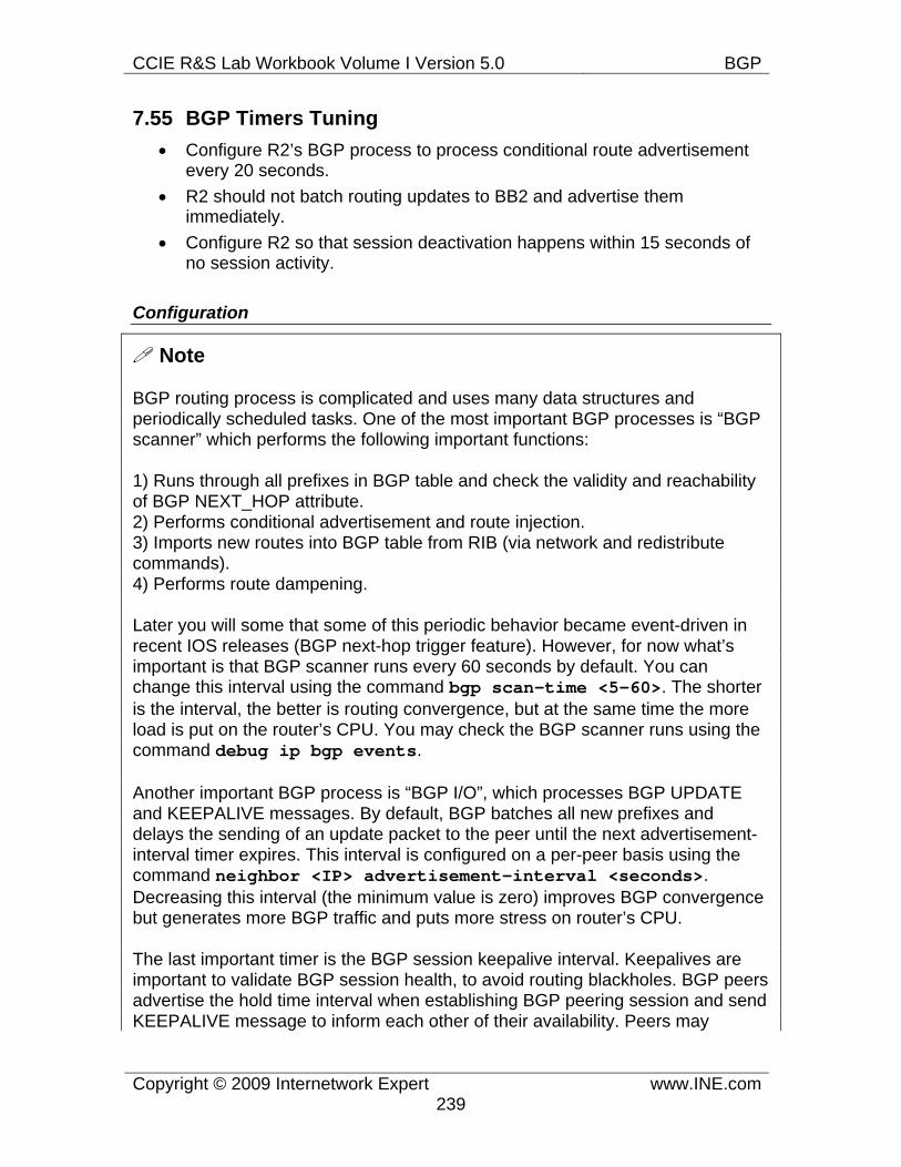
CCIE R&S Lab Workbook Volume I Version 5.0 BGP
Copyright © 2009 Internetwork Expert www.INE.com239
7.55 BGP Timers Tuning • Configure R2’s BGP process to process conditional route advertisement
every 20 seconds. • R2 should not batch routing updates to BB2 and advertise them
immediately. • Configure R2 so that session deactivation happens within 15 seconds of
no session activity.
Configuration
Note
BGP routing process is complicated and uses many data structures and periodically scheduled tasks. One of the most important BGP processes is “BGP scanner” which performs the following important functions:
1) Runs through all prefixes in BGP table and check the validity and reachability of BGP NEXT_HOP attribute. 2) Performs conditional advertisement and route injection. 3) Imports new routes into BGP table from RIB (via network and redistribute commands). 4) Performs route dampening.
Later you will some that some of this periodic behavior became event-driven in recent IOS releases (BGP next-hop trigger feature). However, for now what’s important is that BGP scanner runs every 60 seconds by default. You can change this interval using the command bgp scan-time <5-60>. The shorter is the interval, the better is routing convergence, but at the same time the more load is put on the router’s CPU. You may check the BGP scanner runs using the command debug ip bgp events.
Another important BGP process is “BGP I/O”, which processes BGP UPDATE and KEEPALIVE messages. By default, BGP batches all new prefixes and delays the sending of an update packet to the peer until the next advertisement-interval timer expires. This interval is configured on a per-peer basis using the command neighbor <IP> advertisement-interval <seconds>. Decreasing this interval (the minimum value is zero) improves BGP convergence but generates more BGP traffic and puts more stress on router’s CPU.
The last important timer is the BGP session keepalive interval. Keepalives are important to validate BGP session health, to avoid routing blackholes. BGP peers advertise the hold time interval when establishing BGP peering session and send KEEPALIVE message to inform each other of their availability. Peers may
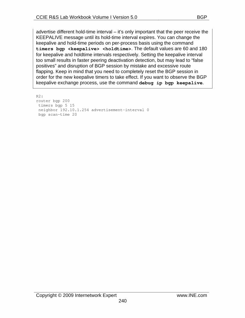
CCIE R&S Lab Workbook Volume I Version 5.0 BGP
Copyright © 2009 Internetwork Expert www.INE.com240
advertise different hold-time interval – it’s only important that the peer receive the KEEPALIVE message until its hold-time interval expires. You can change the keepalive and hold-time periods on per-process basis using the command timers bgp <keepalive> <holdtime>. The default values are 60 and 180 for keepalive and holdtime intervals respectively. Setting the keepalive interval too small results in faster peering deactivation detection, but may lead to “false positives” and disruption of BGP session by mistake and excessive route flapping. Keep in mind that you need to completely reset the BGP session in order for the new keepalive timers to take effect. If you want to observe the BGP keepalive exchange process, use the command debug ip bgp keepalive.
R2: router bgp 200 timers bgp 5 15 neighbor 192.10.1.254 advertisement-interval 0 bgp scan-time 20
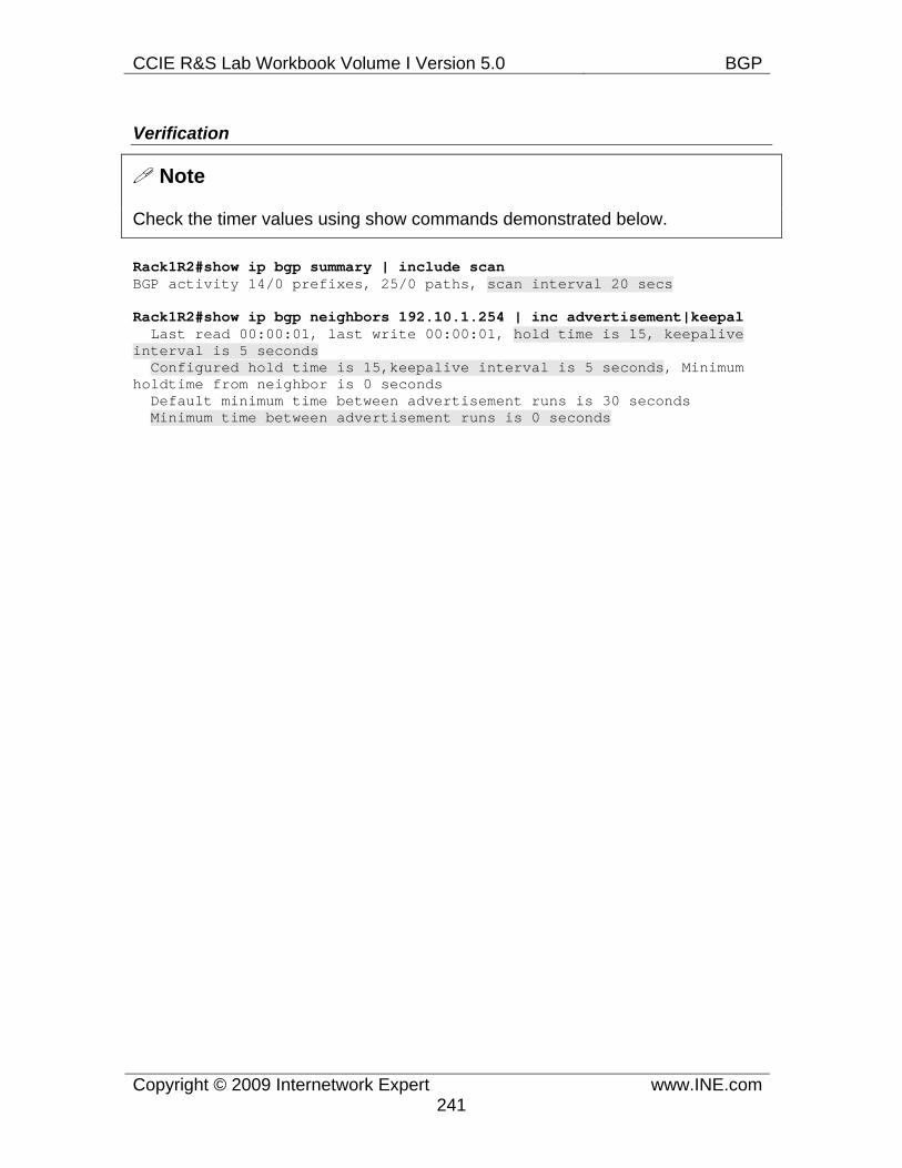
CCIE R&S Lab Workbook Volume I Version 5.0 BGP
Copyright © 2009 Internetwork Expert www.INE.com241
Verification
Note
Check the timer values using show commands demonstrated below.
Rack1R2#show ip bgp summary | include scan BGP activity 14/0 prefixes, 25/0 paths, scan interval 20 secs
Rack1R2#show ip bgp neighbors 192.10.1.254 | inc advertisement|keepal Last read 00:00:01, last write 00:00:01, hold time is 15, keepalive interval is 5 seconds Configured hold time is 15,keepalive interval is 5 seconds, Minimum holdtime from neighbor is 0 seconds Default minimum time between advertisement runs is 30 seconds Minimum time between advertisement runs is 0 seconds
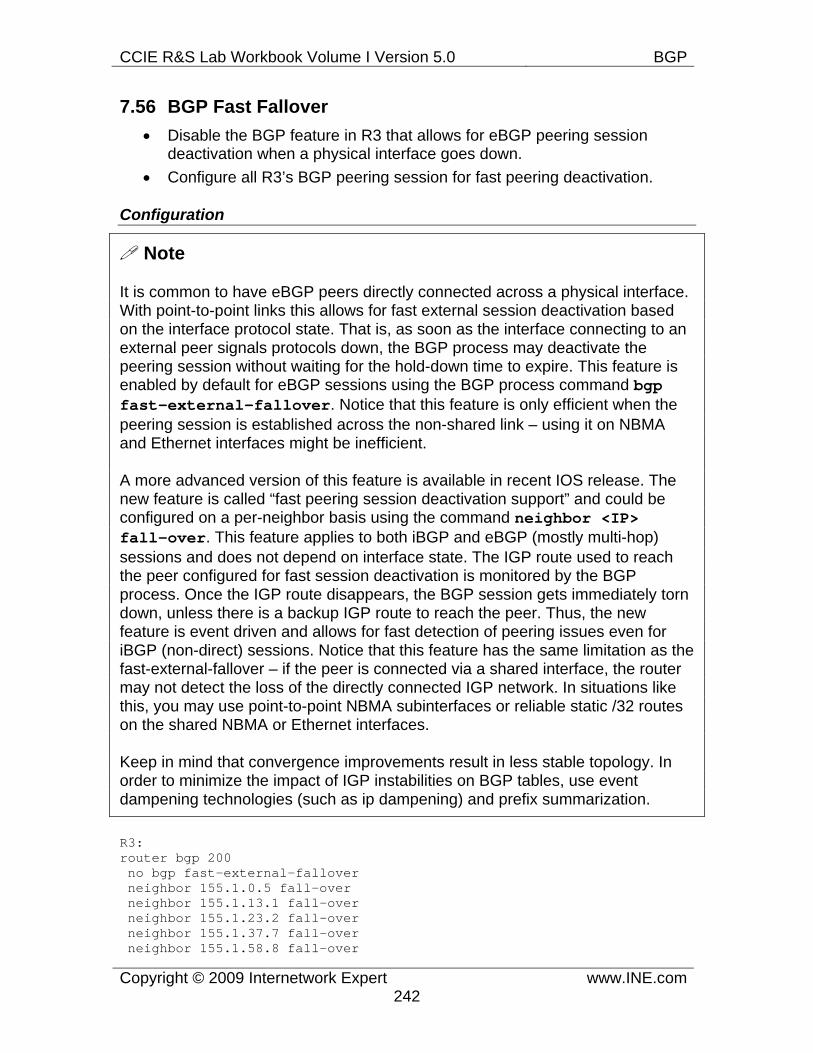
CCIE R&S Lab Workbook Volume I Version 5.0 BGP
Copyright © 2009 Internetwork Expert www.INE.com242
7.56 BGP Fast Fallover • Disable the BGP feature in R3 that allows for eBGP peering session
deactivation when a physical interface goes down. • Configure all R3’s BGP peering session for fast peering deactivation.
Configuration
Note
It is common to have eBGP peers directly connected across a physical interface. With point-to-point links this allows for fast external session deactivation based on the interface protocol state. That is, as soon as the interface connecting to an external peer signals protocols down, the BGP process may deactivate the peering session without waiting for the hold-down time to expire. This feature is enabled by default for eBGP sessions using the BGP process command bgp fast-external-fallover. Notice that this feature is only efficient when the peering session is established across the non-shared link – using it on NBMA and Ethernet interfaces might be inefficient.
A more advanced version of this feature is available in recent IOS release. The new feature is called “fast peering session deactivation support” and could be configured on a per-neighbor basis using the command neighbor <IP> fall-over. This feature applies to both iBGP and eBGP (mostly multi-hop) sessions and does not depend on interface state. The IGP route used to reach the peer configured for fast session deactivation is monitored by the BGP process. Once the IGP route disappears, the BGP session gets immediately torn down, unless there is a backup IGP route to reach the peer. Thus, the new feature is event driven and allows for fast detection of peering issues even for iBGP (non-direct) sessions. Notice that this feature has the same limitation as the fast-external-fallover – if the peer is connected via a shared interface, the router may not detect the loss of the directly connected IGP network. In situations like this, you may use point-to-point NBMA subinterfaces or reliable static /32 routes on the shared NBMA or Ethernet interfaces.
Keep in mind that convergence improvements result in less stable topology. In order to minimize the impact of IGP instabilities on BGP tables, use event dampening technologies (such as ip dampening) and prefix summarization.
R3: router bgp 200 no bgp fast-external-fallover neighbor 155.1.0.5 fall-over neighbor 155.1.13.1 fall-over neighbor 155.1.23.2 fall-over neighbor 155.1.37.7 fall-over neighbor 155.1.58.8 fall-over
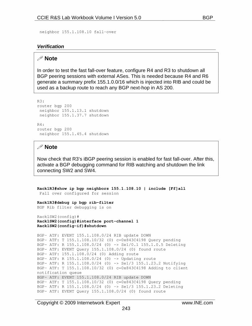
CCIE R&S Lab Workbook Volume I Version 5.0 BGP
Copyright © 2009 Internetwork Expert www.INE.com243
neighbor 155.1.108.10 fall-over
Verification
Note
In order to test the fast fall-over feature, configure R4 and R3 to shutdown all BGP peering sessions with external ASes. This is needed because R4 and R6 generate a summary prefix 155.1.0.0/16 which is injected into RIB and could be used as a backup route to reach any BGP next-hop in AS 200.
R3: router bgp 200 neighbor 155.1.13.1 shutdown neighbor 155.1.37.7 shutdown
R4: router bgp 200 neighbor 155.1.45.4 shutdown
Note
Now check that R3’s iBGP peering session is enabled for fast fall-over. After this, activate a BGP debugging command for RIB watching and shutdown the link connecting SW2 and SW4.
Rack1R3#show ip bgp neighbors 155.1.108.10 | include [Ff]all Fall over configured for session
Rack1R3#debug ip bgp rib-filter BGP Rib filter debugging is on
Rack1SW2(config)# Rack1SW2(config)#interface port-channel 1 Rack1SW2(config-if)#shutdown
BGP- ATF: EVENT 155.1.108.0/24 RIB update DOWN BGP- ATF: T 155.1.108.10/32 (0) c=0x843C4198 Query pending BGP- ATF: R 155.1.108.0/24 (0) -> Se1/0.1 155.1.0.5 Deleting BGP- ATF: EVENT Query 155.1.108.0/24 (0) found route BGP- ATF: 155.1.108.0/24 (0) Adding route BGP- ATF: R 155.1.108.0/24 (0) -> Updating route BGP- ATF: R 155.1.108.0/24 (0) -> Se1/3 155.1.23.2 Notifying BGP- ATF: T 155.1.108.10/32 (0) c=0x843C4198 Adding to client notification queue BGP- ATF: EVENT 155.1.108.0/24 RIB update DOWN BGP- ATF: T 155.1.108.10/32 (0) c=0x843C4198 Query pending BGP- ATF: R 155.1.108.0/24 (0) -> Se1/3 155.1.23.2 Deleting BGP- ATF: EVENT Query 155.1.108.0/24 (0) found route
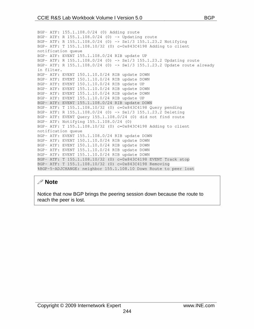
CCIE R&S Lab Workbook Volume I Version 5.0 BGP
Copyright © 2009 Internetwork Expert www.INE.com244
BGP- ATF: 155.1.108.0/24 (0) Adding route BGP- ATF: R 155.1.108.0/24 (0) -> Updating route BGP- ATF: R 155.1.108.0/24 (0) -> Se1/3 155.1.23.2 Notifying BGP- ATF: T 155.1.108.10/32 (0) c=0x843C4198 Adding to client notification queue BGP- ATF: EVENT 155.1.108.0/24 RIB update UP BGP- ATF: R 155.1.108.0/24 (0) -> Se1/3 155.1.23.2 Updating route BGP- ATF: R 155.1.108.0/24 (0) -> Se1/3 155.1.23.2 Update route already in filter. BGP- ATF: EVENT 150.1.10.0/24 RIB update DOWN BGP- ATF: EVENT 150.1.10.0/24 RIB update DOWN BGP- ATF: EVENT 150.1.10.0/24 RIB update UP BGP- ATF: EVENT 155.1.10.0/24 RIB update DOWN BGP- ATF: EVENT 155.1.10.0/24 RIB update DOWN BGP- ATF: EVENT 155.1.10.0/24 RIB update UP BGP- ATF: EVENT 155.1.108.0/24 RIB update DOWN BGP- ATF: T 155.1.108.10/32 (0) c=0x843C4198 Query pending BGP- ATF: R 155.1.108.0/24 (0) -> Se1/3 155.1.23.2 Deleting BGP- ATF: EVENT Query 155.1.108.0/24 (0) did not find route BGP- ATF: Notifying 155.1.108.0/24 (0) BGP- ATF: T 155.1.108.10/32 (0) c=0x843C4198 Adding to client notification queue BGP- ATF: EVENT 155.1.108.0/24 RIB update DOWN BGP- ATF: EVENT 150.1.10.0/24 RIB update DOWN BGP- ATF: EVENT 150.1.10.0/24 RIB update DOWN BGP- ATF: EVENT 155.1.10.0/24 RIB update DOWN BGP- ATF: EVENT 155.1.10.0/24 RIB update DOWN BGP- ATF: T 155.1.108.10/32 (0) c=0x843C4198 EVENT Track stop BGP- ATF: T 155.1.108.10/32 (0) c=0x843C4198 Removing %BGP-5-ADJCHANGE: neighbor 155.1.108.10 Down Route to peer lost
Note
Notice that now BGP brings the peering session down because the route to reach the peer is lost.
CCIE R&S Lab Workbook Volume I Version 5.0 BGP
Copyright © 2009 Internetwork Expert www.INE.com245
7.57 BGP Outbound Route Filtering • R1 and R4 should filter out the prefixes 112.0.0.0/8 and 114.0.0.0/8 from
being advertised to R3 and R5 respectively. • The filtering configuration should be applied to routers R3 and R5.
Configuration
Note
ORF or outbound route filtering is the technique that allows a BGP peer to “push” a filter to the remote neighbor. The neighbor then applies the prefix filter to the outbound updates sent to the peer that pushed the filter. This feature is particularly helpful in situations when BGP peers exchange large amount of BGP information. Applying filtering outbound on the remote peer instead of inbound on the local peer significantly decreases the amount of routing information send across the link. There are two types of ORF filters defined in IETF’s draft – prefix-list based and community based. Cisco IOS supports only the prefix-list ORFs.
In BGP terms, ORF is a special capability negotiated during the establishment of a BGP session. A peer may either advertise its willingness to send, receive or both send and receive the ORFs. You have to enable this capability on peering routers prior to configuring ORFs. The command to enable the feature in the IOS routers is neighbor <IP> capability orf prefix-list {send|receive|both}. You need to reset the BGP session in order to negotiate the new capabilities.
In order to configure and push an ORF, you need to define a prefix list and apply it to the peer’s session using the command neighbor <IP> prefix-list <NAME> in. The list must be inbound, as this is the natural direction for ORF. If the session has ORF send capability enabled, the list will be pushed to the remote peer and installed as and outbound filter after you do a session refresh using the clear ip bgp <IP> soft in prefix-filter command. This command pushes the prefix list and requires route refresh (re-advertisement) from the peer.
R1: router bgp 100 neighbor 155.1.13.3 capability orf prefix-list both
R4: router bgp 100 neighbor 155.1.45.5 capability orf prefix-list both
R3: ip prefix-list ORF deny 112.0.0.0/8 ip prefix-list ORF deny 114.0.0.0/8
CCIE R&S Lab Workbook Volume I Version 5.0 BGP
Copyright © 2009 Internetwork Expert www.INE.com246
ip prefix-list ORF permit 0.0.0.0/0 le 32 ! router bgp 200 neighbor 155.1.13.1 capability orf prefix-list both neighbor 155.1.13.1 prefix-list ORF in
R5: ip prefix-list ORF deny 112.0.0.0/8 ip prefix-list ORF deny 114.0.0.0/8 ip prefix-list ORF permit 0.0.0.0/0 le 32 ! router bgp 200 neighbor 155.1.45.4 capability orf prefix-list both neighbor 155.1.45.4 prefix-list ORF in
CCIE R&S Lab Workbook Volume I Version 5.0 BGP
Copyright © 2009 Internetwork Expert www.INE.com247
Verification
Note
To verify ORFs, issue the following “show” command on any of the routers “pushing” the filters, e.g. on R3. Notice that the new capability has been negotiated and then of the list sent.
Rack1R3#show ip bgp neighbors 155.1.13.1 BGP neighbor is 155.1.13.1, remote AS 100, external link <snip>
For address family: IPv4 Unicast BGP table version 2, neighbor version 2/0 Output queue size : 0 Index 4, Offset 0, Mask 0x10 4 update-group member AF-dependant capabilities: Outbound Route Filter (ORF) type (128) Prefix-list: Send-mode: advertised, received Receive-mode: advertised, received Outbound Route Filter (ORF): sent; Incoming update prefix filter list is ORF Sent Rcvd Prefix activity: ---- ---- Prefixes Current: 0 1 (Consumes 52 bytes) Prefixes Total: 0 1 Implicit Withdraw: 0 0 Explicit Withdraw: 0 0 Used as bestpath: n/a 1 Used as multipath: n/a 0
Outbound Inbound Local Policy Denied Prefixes: -------- ------- Bestpath from this peer: 1 n/a Total: 1 0 Number of NLRIs in the update sent: max 1, min 1 <snip>
Note
Get to the other side of the connection and check the prefix list received by R1. Notice the name for the list, constructed from the peer’s IP address.
Rack1R1#show ip bgp neighbors 155.1.13.3 received prefix-filter Address family: IPv4 Unicast ip prefix-list 155.1.13.3: 3 entries seq 5 deny 112.0.0.0/8 seq 10 deny 114.0.0.0/8 seq 15 permit 0.0.0.0/0 le 32
CCIE R&S Lab Workbook Volume I Version 5.0 BGP
Copyright © 2009 Internetwork Expert www.INE.com248
7.58 BGP Soft Reconfiguration • Configure R4 to accept all prefixes from BB3 irrespective of the configured
inbound filters and store them all locally.
Configuration
Note
Until RFC2918 introduced the Route Refresh capability to BGP it was impossible to signal a remote BGP peer to re-advertise the prefixes (Adj-RIB-Out) to the local peer. This feature is very helpful in situations when the local peer changes inbound filtering policy and needs the peer to re-advertise the routing information. The only way to accomplish the policy refresh was to tear down and re-establish the peering session, which could be very resource consuming and causes connectivity disruption. Before the Route Refresh capability became standardized, one workaround was to use the so-called soft-reconfiguration approach.
When a local BGP speaker is configured to apply soft-reconfiguration to a peer using the command neighbor <IP> soft-reconfiguration inbound the speaker will accept ALL prefixes from the remote peer and store them in a separate memory buffer (of course, a session reset is required for this operation to initialize). The prefixes are then processed via the inbound filters and the resulting information imported into Adj-RIB-In and finally to the BGP table. Every time the local policy changes, there is no need to re-establish the peering session but simply apply the filters to the stored information. The penalty is the extra memory needed to store the routing information from the peer. Of course, this feature became deprecated with the introduction of RR capability.
R4: router bgp 100 neighbor 204.12.1.254 soft-reconfiguration inbound
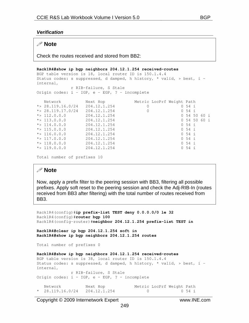
CCIE R&S Lab Workbook Volume I Version 5.0 BGP
Copyright © 2009 Internetwork Expert www.INE.com249
Verification
Note
Check the routes received and stored from BB2:
Rack1R4#show ip bgp neighbors 204.12.1.254 received-routes BGP table version is 18, local router ID is 150.1.4.4 Status codes: s suppressed, d damped, h history, * valid, > best, i - internal, r RIB-failure, S Stale Origin codes: i - IGP, e - EGP, ? - incomplete
Network Next Hop Metric LocPrf Weight Path *> 28.119.16.0/24 204.12.1.254 0 0 54 i *> 28.119.17.0/24 204.12.1.254 0 0 54 i *> 112.0.0.0 204.12.1.254 0 54 50 60 i *> 113.0.0.0 204.12.1.254 0 54 50 60 i *> 114.0.0.0 204.12.1.254 0 54 i *> 115.0.0.0 204.12.1.254 0 54 i *> 116.0.0.0 204.12.1.254 0 54 i *> 117.0.0.0 204.12.1.254 0 54 i *> 118.0.0.0 204.12.1.254 0 54 i *> 119.0.0.0 204.12.1.254 0 54 i
Total number of prefixes 10
Note
Now, apply a prefix filter to the peering session with BB3, filtering all possible prefixes. Apply soft reset to the peering session and check the Adj-RIB-In (routes received from BB3 after filtering) with the total number of routes received from BB3.
Rack1R4(config)#ip prefix-list TEST deny 0.0.0.0/0 le 32Rack1R4(config)#router bgp 100Rack1R4(config-router)#neighbor 204.12.1.254 prefix-list TEST in
Rack1R4#clear ip bgp 204.12.1.254 soft in Rack1R4#show ip bgp neighbors 204.12.1.254 routes
Total number of prefixes 0
Rack1R4#show ip bgp neighbors 204.12.1.254 received-routes BGP table version is 38, local router ID is 150.1.4.4 Status codes: s suppressed, d damped, h history, * valid, > best, i - internal, r RIB-failure, S Stale Origin codes: i - IGP, e - EGP, ? - incomplete
Network Next Hop Metric LocPrf Weight Path * 28.119.16.0/24 204.12.1.254 0 0 54 i
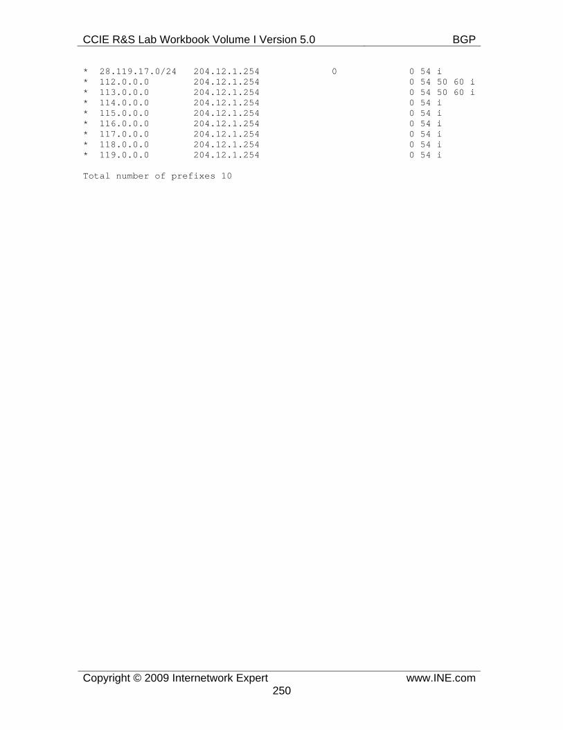
CCIE R&S Lab Workbook Volume I Version 5.0 BGP
Copyright © 2009 Internetwork Expert www.INE.com250
* 28.119.17.0/24 204.12.1.254 0 0 54 i * 112.0.0.0 204.12.1.254 0 54 50 60 i * 113.0.0.0 204.12.1.254 0 54 50 60 i * 114.0.0.0 204.12.1.254 0 54 i * 115.0.0.0 204.12.1.254 0 54 i * 116.0.0.0 204.12.1.254 0 54 i * 117.0.0.0 204.12.1.254 0 54 i * 118.0.0.0 204.12.1.254 0 54 i * 119.0.0.0 204.12.1.254 0 54 i
Total number of prefixes 10
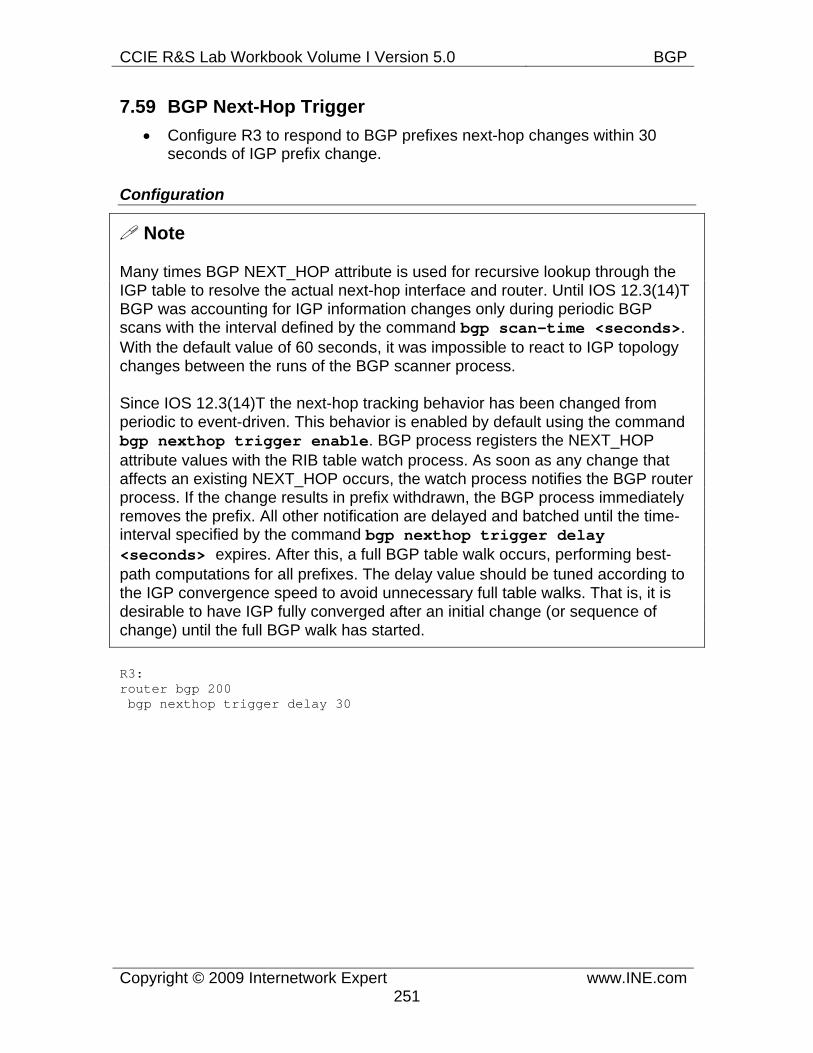
CCIE R&S Lab Workbook Volume I Version 5.0 BGP
Copyright © 2009 Internetwork Expert www.INE.com251
7.59 BGP Next-Hop Trigger • Configure R3 to respond to BGP prefixes next-hop changes within 30
seconds of IGP prefix change.
Configuration
Note
Many times BGP NEXT_HOP attribute is used for recursive lookup through the IGP table to resolve the actual next-hop interface and router. Until IOS 12.3(14)T BGP was accounting for IGP information changes only during periodic BGP scans with the interval defined by the command bgp scan-time <seconds>. With the default value of 60 seconds, it was impossible to react to IGP topology changes between the runs of the BGP scanner process.
Since IOS 12.3(14)T the next-hop tracking behavior has been changed from periodic to event-driven. This behavior is enabled by default using the command bgp nexthop trigger enable. BGP process registers the NEXT_HOP attribute values with the RIB table watch process. As soon as any change that affects an existing NEXT_HOP occurs, the watch process notifies the BGP router process. If the change results in prefix withdrawn, the BGP process immediately removes the prefix. All other notification are delayed and batched until the time-interval specified by the command bgp nexthop trigger delay <seconds> expires. After this, a full BGP table walk occurs, performing best-path computations for all prefixes. The delay value should be tuned according to the IGP convergence speed to avoid unnecessary full table walks. That is, it is desirable to have IGP fully converged after an initial change (or sequence of change) until the full BGP walk has started.
R3: router bgp 200 bgp nexthop trigger delay 30
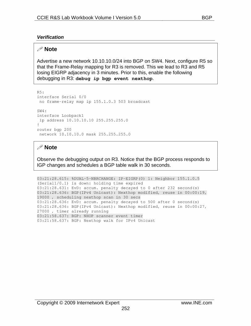
CCIE R&S Lab Workbook Volume I Version 5.0 BGP
Copyright © 2009 Internetwork Expert www.INE.com252
Verification
Note
Advertise a new network 10.10.10.0/24 into BGP on SW4. Next, configure R5 so that the Frame-Relay mapping for R3 is removed. This we lead to R3 and R5 losing EIGRP adjacency in 3 minutes. Prior to this, enable the following debugging in R3: debug ip bgp event nexthop.
R5: interface Serial 0/0 no frame-relay map ip 155.1.0.3 503 broadcast
SW4: interface Loobpack1 ip address 10.10.10.10 255.255.255.0 ! router bgp 200 network 10.10.10.0 mask 255.255.255.0
Note
Observe the debugging output on R3. Notice that the BGP process responds to IGP changes and schedules a BGP table walk in 30 seconds.
03:21:28.615: %DUAL-5-NBRCHANGE: IP-EIGRP(0) 1: Neighbor 155.1.0.5 (Serial1/0.1) is down: holding time expired 03:21:28.631: EvD: accum. penalty decayed to 0 after 232 second(s) 03:21:28.636: BGP(IPv4 Unicast): Nexthop modified, reuse in 00:00:19, 19000 , scheduling nexthop scan in 30 secs 03:21:28.636: EvD: accum. penalty decayed to 500 after 0 second(s) 03:21:28.636: BGP(IPv4 Unicast): Nexthop modified, reuse in 00:00:27, 27000 , timer already running 03:21:58.637: BGP: NHOP scanner event timer 03:21:58.637: BGP: Nexthop walk for IPv4 Unicast
CCIE R&S Lab Workbook Volume I Version 5.0 BGP
Copyright © 2009 Internetwork Expert www.INE.com253
7.60 BGP TTL Security • Configure R3 to accept TCP packets from eBGP peers only if they are no
more than one hop away.
Configuration
Note
General TTL Security Mechanism (GTSM) defined in RFC 3682 specifies a protection method against BGP session hijacking and resource exhaustion attacks. Generally, BGP process listens on the TCP port 139 and accepts all TCP SYN packets destined to this port, unless they are filtered by an ACL. It is possible to generate a barrage of spoofed packets imitating a valid BGP session and inject false information (if the session is unauthenticated) or generate a TCP SYN-flooding attack.
GTSM utilizes the simple fact that every router on the path to the BGP speaker decrements the TTL field in IP packets by one. Based on this, it is possible to identify potentially spoofed packets by looking at their TTL field – the packets send from “afar” will have the TTL field below some threshold. It is possible to define a “secure radius” in the number of hop counts to accept the incoming IP packets. For example, if all BGP peers are within 10 hops away from the local BGP speaker, then all incoming IP packets will have their TTL field set to at no less than 245. This is because all IP packets start with TTL=255 and the field is decremented by every hop on the path. Thus, by accepting the IP packets with TTL greater than or equal to 245 it is possible to minimize the risk of spoofed packets reaching the BGP process. Notice that the usefulness of GTSM feature decreases as the diameter of eBGP Multihop session grows.
In order to configure the TTL security checks for a BGP peer use the command neighbor <IP> ttl-security hops <hop-count>. This command applies to eBGP peering sessions only (either directly-connected or multihop) and specifies the number of hops the remote peer could be away from the local speaker. Keep in mind the internal BGP sessions are not protected, and therefore the internal network assumed to be “trusted”. All packets incoming TCP packets targeted at BGP port with the IP TTL value below (255 - <hop-count>) are silently discarded by the router. In addition, the feature sets TTL value for outgoing TCP/IP packets to 255-<hop-count> to make sure the remote peer will accept the local packets. The GTSM feature is mutually exclusive with the ebgp-multihop BGP feature. This is because the eBGP session by default sets TTL=1 in the outgoing IP packets and with the multihop <n> session parameter, the TTL value is set to <n>, which is not compatible with GTSM Therefore, make sure you configured GTSM feature on both sides of the peering link.
CCIE R&S Lab Workbook Volume I Version 5.0 BGP
Copyright © 2009 Internetwork Expert www.INE.com254
R1: router bgp 100 neighbor 155.1.13.3 ttl-security hops 1
R3: router bgp 200 neighbor 155.1.13.1 ttl-security hops 1 neighbor 155.1.37.7 ttl-security hops 1
SW1: router bgp 300 neighbor 155.1.37.3 ttl-security hops 1
Verification
Note
Check the GTSM settings for eBGP peers on R3. Repeat the same verifications on R1 and SW1.
Rack1R3#show ip bgp neighbors 155.1.13.1 | inc hop External BGP neighbor may be up to 1 hop away.
Rack1R3#show ip bgp neighbors 155.1.37.7 | inc hop External BGP neighbor may be up to 1 hop away.
CCIE R&S Lab Workbook Volume I Version 5.0 BGP
Copyright © 2009 Internetwork Expert www.INE.com255
7.61 BGP AllowAS in • Configure R2 and SW2 to advertise networks 2.2.2.0/24 and 8.8.8.0/24
into BGP. • Configure AS 200 border routers so that in case AS 200 is partitioned, the
remaining segments could transit AS 100 to recover connectivity.
Configuration
Note
BGP loop-prevention mechanism does not allow a BGP speaker to accept prefixes with the local AS number in the AS_PATH list. However, in some cases, it would be desirable to accept the routes originated in the same AS via another AS. There are two common scenarios:
1) The company’s network is partitioned and every partition connects to the Internet or ISP. Every network has its own set of prefixes but uses the same AS number. In this case, in order for the partitions to exchange prefixes they must accept the NLRIs with the same AS number.
2) The company connects to an ISP and wants to use it as a transit path in case the company’s network becomes segmented due to an emergency. In this case, the prefixes advertised to the ISP must be accepted back by the border peers.
Cisco IOS allows for accepting the prefixes with the local AS number from a specific peer using the command neighbor <IP> allowas-in [<count>]. Here <count> is the number of the local AS number occurrences in the AS_PATH attribute, which defaults to one. This parameter serves the purpose similar to the hop-count limit in distance-vector protocol and implement the well-know count-to-infinity loop prevention technique.
In order to prevent routing loops with this feature, you should be careful implementing prefix aggregation. Specifically, only one “partition” or border peer could implement summarization, or summarization should not be used at all. Otherwise, the upstream ASes will have troubles selecting the proper entry point to the AS partitions. Needless to mention that using the AllowAS in feature is highly un-recommended and only advised as a last resort.
CCIE R&S Lab Workbook Volume I Version 5.0 BGP
Copyright © 2009 Internetwork Expert www.INE.com256
R2: router bgp 200 network 2.2.2.0 mask 255.255.255.0 ! interface Loopback1 ip address 2.2.2.2 255.255.255.0
R3: router bgp 200 neighbor 155.1.13.1 allowas-in
R5: router bgp 200 neighbor 155.1.45.4 allowas-in
SW2: router bgp 200 network 8.8.8.0 mask 255.255.255.0 ! interface Loopback1 ip address 8.8.8.8 255.255.255.0
CCIE R&S Lab Workbook Volume I Version 5.0 BGP
Copyright © 2009 Internetwork Expert www.INE.com257
Verification
Note
Configure the routers so that AS 200 split in two parts. To accomplish this, configure the routers as follows:
R3: router eigrp 1 passive-interface FastEthernet 0/0 passive-interface Serial 1/2
R5: router eigrp 1 passive-interface Serial 0/0 passive-interface Serial 0/1 ! interface Serial 0/0 shutdown
Note
Check the BGP tables of R3 and R5 for the prefixes originated in AS 200. Notice that both R3 and R5 accept those prefixes due to the AllowAS in feature. Next, trace the route from R2 to SW2 between the two configured subnets and make sure connectivity is maintained.
Rack1R3#show ip bgp regexp _200$ BGP table version is 79, local router ID is 150.1.3.3 Status codes: s suppressed, d damped, h history, * valid, > best, i - internal, r RIB-failure, S Stale Origin codes: i - IGP, e - EGP, ? - incomplete
Network Next Hop Metric LocPrf Weight Path *> 8.8.8.0/24 155.1.13.1 0 100 200 i
Rack1R5#show ip bgp regexp _200$ BGP table version is 94, local router ID is 150.1.5.5 Status codes: s suppressed, d damped, h history, * valid, > best, i - internal, r RIB-failure, S Stale Origin codes: i - IGP, e - EGP, ? - incomplete
Network Next Hop Metric LocPrf Weight Path *> 2.2.2.0/24 155.1.45.4 0 100 200 i
Rack1R2#traceroute 8.8.8.8 source loopback 1
Type escape sequence to abort.
CCIE R&S Lab Workbook Volume I Version 5.0 BGP
Copyright © 2009 Internetwork Expert www.INE.com258
Tracing the route to 8.8.8.8
1 155.1.23.3 [AS 100] 16 msec 16 msec 16 msec 2 155.1.13.1 [AS 100] 28 msec 28 msec 32 msec 3 155.1.146.4 [AS 100] 28 msec 28 msec 32 msec 4 155.1.45.5 [AS 100] 40 msec 44 msec 40 msec 5 155.1.58.8 [AS 100] 44 msec * 40 msec