Embed Size (px)
Citation preview
IEEE TRANSACTIONS ON INTELLIGENT TRANSPORTATION SYSTEMS, VOL. 15, NO. 2, APRIL 2014 607
Estimating Speed Using a Side-LookingSingle-Radar Vehicle Detector
Shyr-Long Jeng, Wei-Hua Chieng, and Hsiang-Pin Lu
Abstract—This paper presents a side-looking single-beam mi-crowave vehicle detector (VD) system for estimation of per-vehiclespeed and length. The proposed VD system is equipped with a 2-Drange Doppler frequency-modulated continuous-wave (FMCW)radar using a squint angle. The associated Fourier processor usesan inverse synthetic aperture radar (ISAR) algorithm to extractrange and speed data for each vehicle using a single-beam FMCWradar. The simulation and experimental results show accurateestimations of vehicle speed and length. The measurement errorsof speed and length were approximately ±4 km/h and ±1 m,respectively. The proposed method has excellent detection capa-bility for small moving targets, such as bikes and pedestrians, atspeeds down to 5 km/h. A commercial 10.6-GHz radar with signalprocessing modifications was used in the experiments.
Index Terms—Frequency-modulated continuous wave(FMCW), intelligent transportation system (ITS), syntheticaperture radar (SAR), vehicle detector (VD).
I. INTRODUCTION
V EHICLE detectors (VDs) are widely used to gather trafficinformation in an intelligent transportation system (ITS).
The objective of a VD is to obtain traffic information, such asthe speed and length of vehicles passing on a road. A wide rangeof sensor technologies are available for VDs, such as inductiveloops, video, ultrasonic detectors, and microwave detectors.The advantage of radar-based detectors is that they are a maturetechnology because of past military applications. Radar-baseddetectors are unintrusive and can operate day or night in anyweather conditions. A frequency-modulated continuous-wave(FMCW) radar is widely used for traffic data collection. Ittransmits a continuous-wave (CW) signal and compares thefrequency difference between the transmitted and reflectedsignals to estimate the vehicle range and its speed.
The installation methods of radar-based detectors can beclassified as forward-looking and side-looking (or roadside).Forward-looking detectors have an illuminative direction paral-lel to the direction of traffic and are applied only to a single lane
Manuscript received May 17, 2013; revised July 9, 2013 and September 17,2013; accepted September 19, 2013. Date of publication October 17, 2013; dateof current version March 28, 2014. This work was supported by the NationalScience Council of Taiwan under Contract NSC 101-3113-E-009-006. TheAssociate Editor for this paper was F. Zhu.
S.-L. Jeng is with the Department of Electrical and Electronic Engineering,Ta Hwa University of Science and Technology, Hsinchu 307, Taiwan (e-mail:[email protected]).
W.-H. Chieng and H.-P. Lu are with the Department of Mechanical En-gineering, National Chiao Tung University, Hsinchu 300, Taiwan (e-mail:[email protected]; [email protected]).
Color versions of one or more of the figures in this paper are available onlineat http://ieeexplore.ieee.org.
Digital Object Identifier 10.1109/TITS.2013.2283528
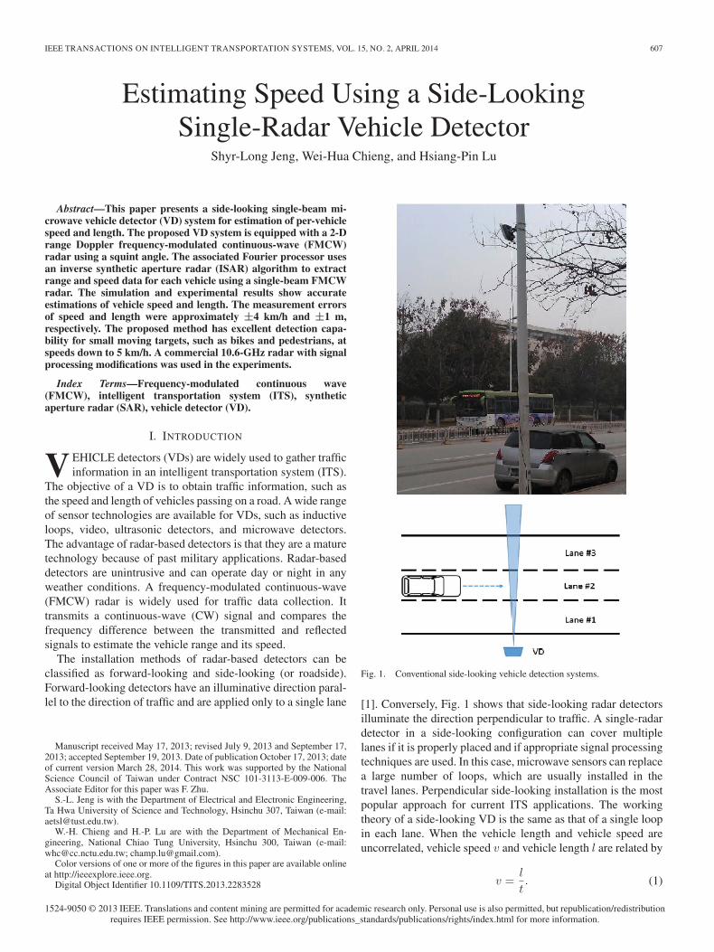
Fig. 1. Conventional side-looking vehicle detection systems.
[1]. Conversely, Fig. 1 shows that side-looking radar detectorsilluminate the direction perpendicular to traffic. A single-radardetector in a side-looking configuration can cover multiplelanes if it is properly placed and if appropriate signal processingtechniques are used. In this case, microwave sensors can replacea large number of loops, which are usually installed in thetravel lanes. Perpendicular side-looking installation is the mostpopular approach for current ITS applications. The workingtheory of a side-looking VD is the same as that of a single loopin each lane. When the vehicle length and vehicle speed areuncorrelated, vehicle speed v and vehicle length l are related by
v =l
t. (1)
1524-9050 © 2013 IEEE. Translations and content mining are permitted for academic research only. Personal use is also permitted, but republication/redistributionrequires IEEE permission. See http://www.ieee.org/publications_standards/publications/rights/index.html for more information.
608 IEEE TRANSACTIONS ON INTELLIGENT TRANSPORTATION SYSTEMS, VOL. 15, NO. 2, APRIL 2014
These parameters cannot be independently measured in asingle loop. A single loop can only detect dwell time t. Vehiclelength l is typically set to a constant value, and (1) is used toestimate speed from single-loop measurements. However, thisapproach does not consider varying vehicle lengths. During alow flow, a long vehicle can skew statistical data because itrequires more time to pass the detector. Many studies [2]–[4]have addressed this problem.
Most side-looking radars can measure only the dwell timeof a vehicle passing through the radar sensing zone. A single-beam radar served as a single induced loop to estimate speedbased on the dwell time. Although dual-radar detectors canprovide more accurate speeds and vehicle classifications bymeasuring the time difference between two radar beams, theyencounter a number of problems. First, they require a highlyprecise installation to ensure perpendicularity to the directionof traffic; otherwise, matching the detected signals between tworadars is difficult. The second problem is that the performancecan be inhibited when one of the radar signals is blocked bynearby vehicles in traffic jam scenarios.
The conventional installation of a side-looking radar does notuse the advantage of detecting the Doppler effect of microwavedetectors because the returned Doppler frequency generated bythe vehicle is weak. Prior studies [5], [6] have detected theweak Doppler shift for measuring real-time speed by usingwide beam antennas. The disadvantage of this approach isdegradation in range accuracy. Many other studies [7], [8]have used various waveforms and frequencies to obtain rangeand speed information. Because of the weak Doppler effect,the perpendicular side-looking VD cannot apply the typicalFMCW speed detection method by comparing beat frequenciesof up and down sweeps [9] or the displacement difference [10].Therefore, it is crucial to develop an appropriate method witha narrow-beam single-radar detector to provide accurate range,speed, and vehicle classification estimates.
This paper proposes a novel radar system to detect multiplevehicles in multiple lanes. The following section presents theassociated FMCW radar measurement scheme and the asso-ciated 2-D range Doppler FMCW radar Fourier processingmethod. The range and Doppler frequency were obtained usingthe 2-D fast Fourier transform (FFT) technique [11] widelyused in inverse synthetic aperture radar (ISAR) signal process-ing [12]–[15]. Vehicle detection was performed by using a high-speed digital signal processor (DSP) and a 10.6-GHz FMCWfront end. This paper also presents an algorithm to measure thespeed and vehicle length by using a fixed single-radar module.
The remainder of this paper is organized as follows.Section II briefly describes the derivation of the proposedmethod and Section III presents the measurement resultsto illustrate the capability of the proposed method. Finally,Section IV concludes the study.
II. PROPOSED METHOD
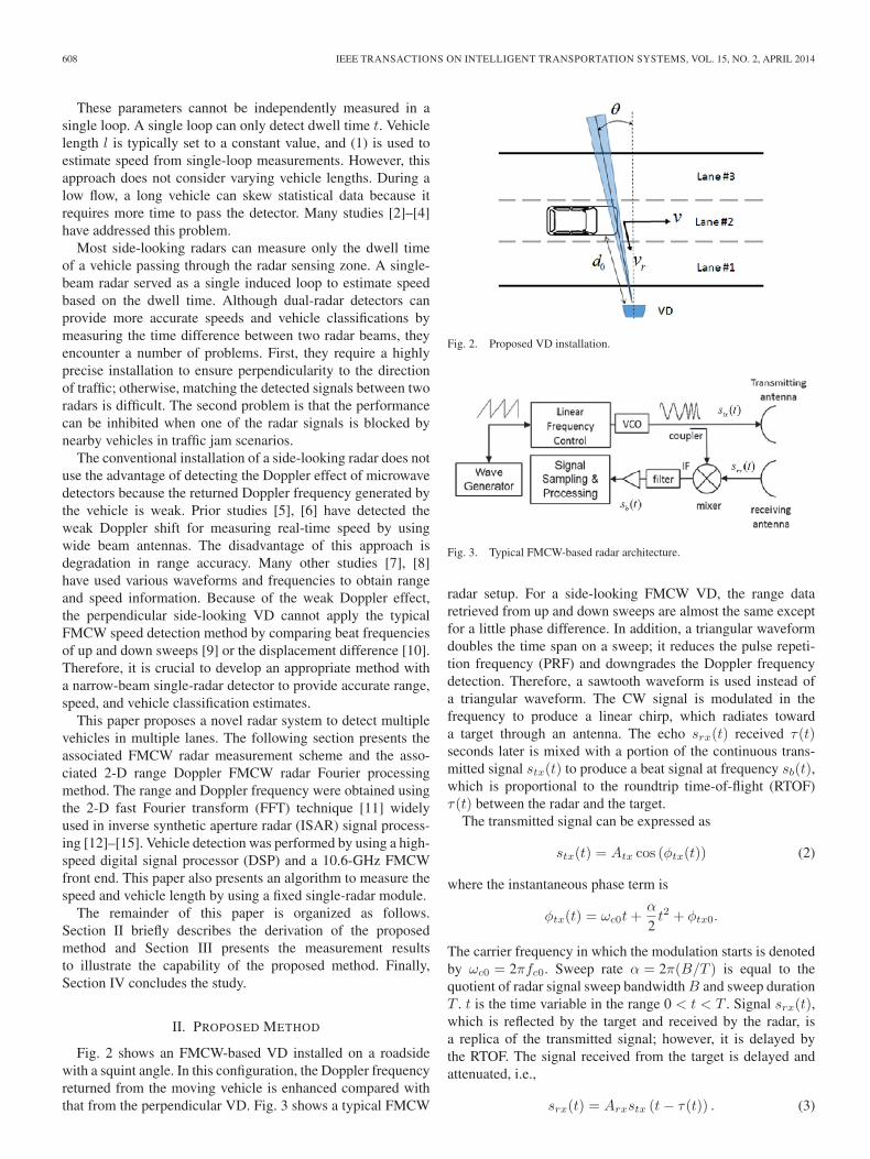
Fig. 2 shows an FMCW-based VD installed on a roadsidewith a squint angle. In this configuration, the Doppler frequencyreturned from the moving vehicle is enhanced compared withthat from the perpendicular VD. Fig. 3 shows a typical FMCW
Fig. 2. Proposed VD installation.
Fig. 3. Typical FMCW-based radar architecture.
radar setup. For a side-looking FMCW VD, the range dataretrieved from up and down sweeps are almost the same exceptfor a little phase difference. In addition, a triangular waveformdoubles the time span on a sweep; it reduces the pulse repeti-tion frequency (PRF) and downgrades the Doppler frequencydetection. Therefore, a sawtooth waveform is used instead ofa triangular waveform. The CW signal is modulated in thefrequency to produce a linear chirp, which radiates towarda target through an antenna. The echo srx(t) received τ(t)seconds later is mixed with a portion of the continuous trans-mitted signal stx(t) to produce a beat signal at frequency sb(t),which is proportional to the roundtrip time-of-flight (RTOF)τ(t) between the radar and the target.
The transmitted signal can be expressed as
stx(t) = Atx cos (φtx(t)) (2)
where the instantaneous phase term is
φtx(t) = ωc0t+α
2t2 + φtx0.
The carrier frequency in which the modulation starts is denotedby ωc0 = 2πfc0. Sweep rate α = 2π(B/T ) is equal to thequotient of radar signal sweep bandwidth B and sweep durationT . t is the time variable in the range 0 < t < T . Signal srx(t),which is reflected by the target and received by the radar, isa replica of the transmitted signal; however, it is delayed bythe RTOF. The signal received from the target is delayed andattenuated, i.e.,
srx(t) = Arxstx (t− τ(t)) . (3)
JENG et al.: ESTIMATING SPEED USING A SIDE-LOOKING SINGLE-RADAR VEHICLE DETECTOR 609
The received and transmitted signals, i.e., srx(t) and stx(t), aremultiplied in the mixer. A low-pass filter is used to suppress thesignal components located at the double carrier frequency. Bysolving the multiplication and considering (2) and (3), a beatsignal was obtained as
sb(t) = Ab cos
(ωc0τ(t) + ατ(t)t− 1
2ατ(t)2
). (4)
Consider a target located at distance d at time t = 0 andmoving at speed v. The target reflects the FMCW signal trans-mitted by the radar unit. Vehicle distance d(t+ kTr) is definedas the range from the sensor to the vehicle at the kth sweep.d(t+ kTr) is derived by
d(t+ kTr) = d0 + vr · (t+ kTr), k = 0, 1, 2, . . . , N − 1
where vr denotes the radial component of the vehicle speed atsquint angle θ. Tr denotes the pulse repetition interval (PRI).
During NTr, the coherent processing interval (CPI), thespeed is assumed to be constant, and the RTOF τ(t+ kTr)between the radar and the target is defined as
τ(t+ kTr) ≡2d(t+ kTr)
c
=2c(d0 + vr · (t+ kTr))
= τ0 + 2vrc(t+ kTr) (5)
where τ0 is the RTOF when the vehicle is at the initial range d0.Replacing τ(t) in (4) with (5) derives a 2-D beat signal, i.e.,
sb(t, kTr) = Ab cos(φb) (6)
where
φb(t, kTr)
= ωc0τ(t+ kTr) + ατ(t+ kTr)t−12ατ(t+ kTr)
2
= ωc0τ0 + 2ωc0vrc(t+ kTr) + ατ0t+ 2α
vrc(t+ kTr)t
− 12α
[τ20 + 4τ0
vrc(t+ kTr) + 4
(vrc
)2
(t+ kTr)2
]
= ωc0τ0 +(
2ωc0vrc
+ ατ0 − 2ατ0vrc
)t
+(
2ωc0vrc
− 2ατ0vrc
)kTr −
12ατ20
+ 2αvrc
(1 − vr
c
)t2 + 2α
vrc
(1 − vr
c
)tkTr
− 2α(vrc
)2
(kTr)2.
Without a loss of generality, this discussion assumes(vr/c) � 1, and the term 2α(vr/c)2(kTr)
2 is ignored. Equa-tion (6) can be rewritten as
φb(t, kTr)
=
(ωc0
2vrc
+ατ0
)t+
(ωc0
2vrc
)kTr+
(ωc0τ0−
12ατ20
)
= ωRt+ ωDkTr + φ0 (7)
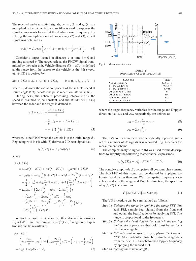
Fig. 4. Measurement scheme.
TABLE IPARAMETERS USED IN SIMULATION
where the target frequency variables for the range and Dopplerdirection, i.e., ωR and ωD, respectively, are defined as
ωR = 2ωc0vrc
+ ατ0 (8)
ωD = 2ωc0vrc. (9)
The FMCW measurement was periodically repeated, and aset of a number of N signals was recorded. Fig. 4 depicts themeasurement scheme.
The complex analytic signal in (6) was used for the descrip-tions to simplify the following mathematical expressions:
sb(t, kTr) = A′b · ej(ωD ·kTr+ωR·t). (10)
The complex amplitude A′b comprises all constant phase terms.
The 2-D FFT of this signal can be derived by applying theFourier modulation theorem. With the spatial frequency vari-ables r and v in the range and Doppler direction, the spectrumof sb(t, kTr) is derived as
F {sb(t, kTr)} = Sb(r, v). (11)
The VD procedure can be summarized as follows.
Step 1) Estimate the range by applying the range FFT: Foreach PRI, sample beat signals from the front endand obtain the beat frequency by applying FFT. Therange is proportional to the frequency.
Step 2) Estimate the dwell time of the vehicle in the sensingregion: An appropriate threshold must be set for aparticular range bin.
Step 3) Estimate vehicle speed v by applying the DopplerFFT: At a particular range bin, sample range datafrom the first FFT and obtain the Doppler frequencyby applying the second FFT.
Step 4) Identify the vehicle length.
610 IEEE TRANSACTIONS ON INTELLIGENT TRANSPORTATION SYSTEMS, VOL. 15, NO. 2, APRIL 2014
Fig. 5. Simulated 2-D spectrum of three moving vehicles. (a) Range spectraof three vehicles. (b) Range/speed spectra of three vehicles. (c) Range/speedspectra of three vehicles in 3-D.
The simulation used a data set for three vehicles simulta-neously traveling distances of 10, 20, and 30 m through thedetection zone at speeds of 10, 60, and 40 km/h, respectively.Table I shows the sensor parameters.
The target range and speed can be unambiguously deter-mined by evaluating the positions of the three 2-D impulsesbased on (8) and (9). Fig. 5(a) shows that the range informationfor the vehicles was obtained by applying the range FFT forall sweep data. The speed information of each vehicle can beacquired during each CPI by applying a second FFT at eachfixed range, because only one vehicle is at each fixed range.
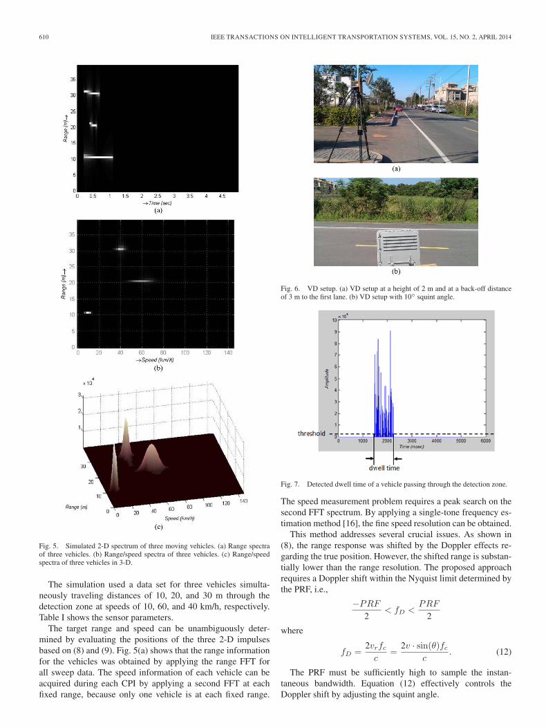
Fig. 6. VD setup. (a) VD setup at a height of 2 m and at a back-off distanceof 3 m to the first lane. (b) VD setup with 10◦ squint angle.
Fig. 7. Detected dwell time of a vehicle passing through the detection zone.
The speed measurement problem requires a peak search on thesecond FFT spectrum. By applying a single-tone frequency es-timation method [16], the fine speed resolution can be obtained.
This method addresses several crucial issues. As shown in(8), the range response was shifted by the Doppler effects re-garding the true position. However, the shifted range is substan-tially lower than the range resolution. The proposed approachrequires a Doppler shift within the Nyquist limit determined bythe PRF, i.e.,
−PRF
2< fD <
PRF
2
where
fD =2vrfcc
=2v · sin(θ)fc
c. (12)
The PRF must be sufficiently high to sample the instan-taneous bandwidth. Equation (12) effectively controls theDoppler shift by adjusting the squint angle.
JENG et al.: ESTIMATING SPEED USING A SIDE-LOOKING SINGLE-RADAR VEHICLE DETECTOR 611
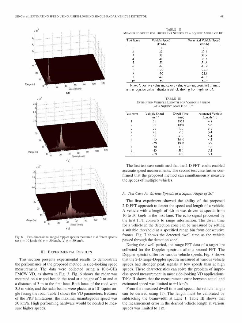
Fig. 8. Two-dimensional range/Doppler spectra measured at different speeds.(a) v = 10 km/h. (b) v = 30 km/h. (c) v = 50 km/h.
III. EXPERIMENTAL RESULTS
This section presents experimental results to demonstratethe performance of the proposed method in side-looking speedmeasurement. The data were collected using a 10.6-GHzFMCW VD, as shown in Fig. 3. Fig. 6 shows the radar wasmounted on a tripod beside the road at a height of 2 m and ata distance of 3 m to the first lane. Both lanes of the road were3.5 m wide, and the radar beams were placed at a 10◦ squint an-gle facing the road. Table I shows the VD parameters. Becauseof the PRF limitations, the maximal unambiguous speed was50 km/h. High performing hardware would be needed to mea-sure higher speeds.
TABLE IIMEASURED SPEED FOR DIFFERENT SPEEDS AT A SQUINT ANGLE OF 10◦
TABLE IIIESTIMATED VEHICLE LENGTH FOR VARIOUS SPEEDS
AT A SQUINT ANGLE OF 10◦
The first test case confirmed that the 2-D FFT results enabledaccurate speed measurements. The second test case further con-firmed that the proposed method can simultaneously measurethe speeds of multiple vehicles.
A. Test Case A: Various Speeds at a Squint Angle of 20◦
The first experiment showed the ability of the proposed2-D FFT approach to detect the speed and length of a vehicle.A vehicle with a length of 4.6 m was driven at speeds from10 to 50 km/h in the first lane. The echo signal processed bythe first FFT converts to range information. The dwell timefor a vehicle in the detection zone can be measured by settinga suitable threshold at a specified range bin from consecutiveframes. Fig. 7 shows the detected dwell time as the vehiclepassed through the detection zone.
During the dwell period, the range FFT data of a target arecollected for the Doppler spectrum after a second FFT. TheDoppler spectra differ for various vehicle speeds. Fig. 8 showsthat the 2-D range-Doppler spectra measured at various vehiclespeeds had stronger peak signals at low speeds than at highspeeds. These characteristics can solve the problem of impre-cise speed measurement in most side-looking VD applications.Table II shows that the measurement error between actual andestimated speed was limited to ±4 km/h.
From the measured dwell time and speed, the vehicle lengthcan be derived using (1). The length must be calibrated bysubtracting the beamwidth at Lane 1. Table III shows thatthe measurement error in the derived vehicle length at variousspeeds was limited to 1 m.
612 IEEE TRANSACTIONS ON INTELLIGENT TRANSPORTATION SYSTEMS, VOL. 15, NO. 2, APRIL 2014
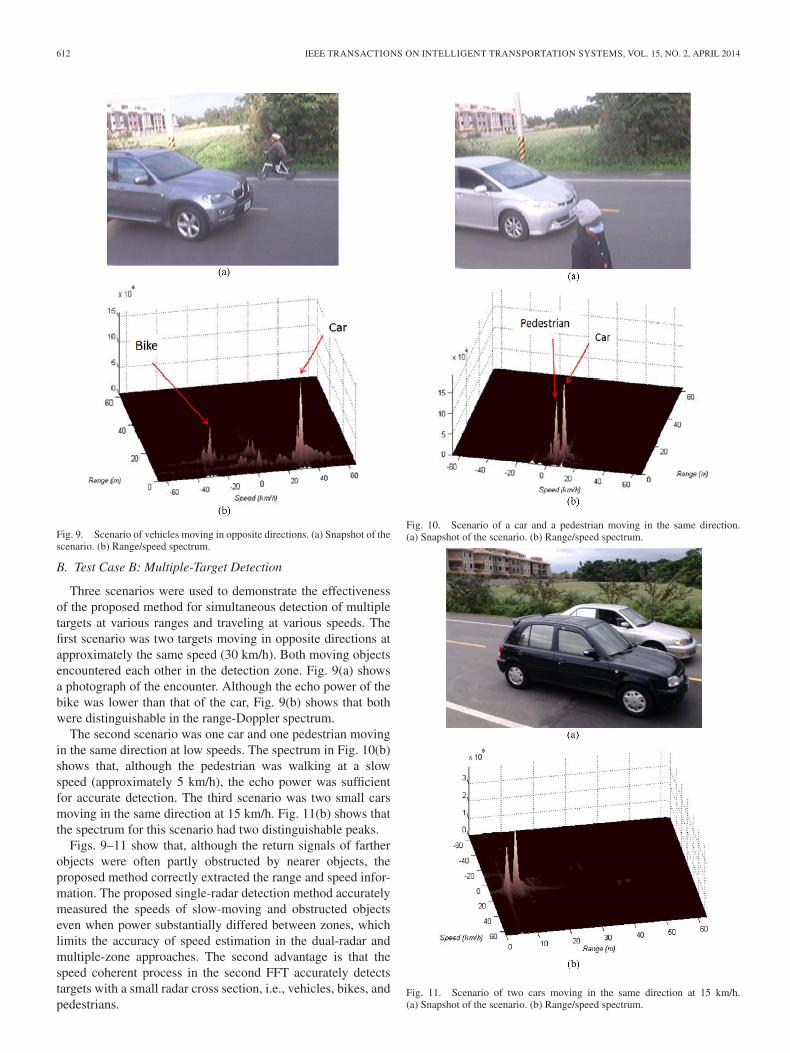
Fig. 9. Scenario of vehicles moving in opposite directions. (a) Snapshot of thescenario. (b) Range/speed spectrum.
B. Test Case B: Multiple-Target Detection
Three scenarios were used to demonstrate the effectivenessof the proposed method for simultaneous detection of multipletargets at various ranges and traveling at various speeds. Thefirst scenario was two targets moving in opposite directions atapproximately the same speed (30 km/h). Both moving objectsencountered each other in the detection zone. Fig. 9(a) showsa photograph of the encounter. Although the echo power of thebike was lower than that of the car, Fig. 9(b) shows that bothwere distinguishable in the range-Doppler spectrum.
The second scenario was one car and one pedestrian movingin the same direction at low speeds. The spectrum in Fig. 10(b)shows that, although the pedestrian was walking at a slowspeed (approximately 5 km/h), the echo power was sufficientfor accurate detection. The third scenario was two small carsmoving in the same direction at 15 km/h. Fig. 11(b) shows thatthe spectrum for this scenario had two distinguishable peaks.
Figs. 9–11 show that, although the return signals of fartherobjects were often partly obstructed by nearer objects, theproposed method correctly extracted the range and speed infor-mation. The proposed single-radar detection method accuratelymeasured the speeds of slow-moving and obstructed objectseven when power substantially differed between zones, whichlimits the accuracy of speed estimation in the dual-radar andmultiple-zone approaches. The second advantage is that thespeed coherent process in the second FFT accurately detectstargets with a small radar cross section, i.e., vehicles, bikes, andpedestrians.
Fig. 10. Scenario of a car and a pedestrian moving in the same direction.(a) Snapshot of the scenario. (b) Range/speed spectrum.
Fig. 11. Scenario of two cars moving in the same direction at 15 km/h.(a) Snapshot of the scenario. (b) Range/speed spectrum.
JENG et al.: ESTIMATING SPEED USING A SIDE-LOOKING SINGLE-RADAR VEHICLE DETECTOR 613
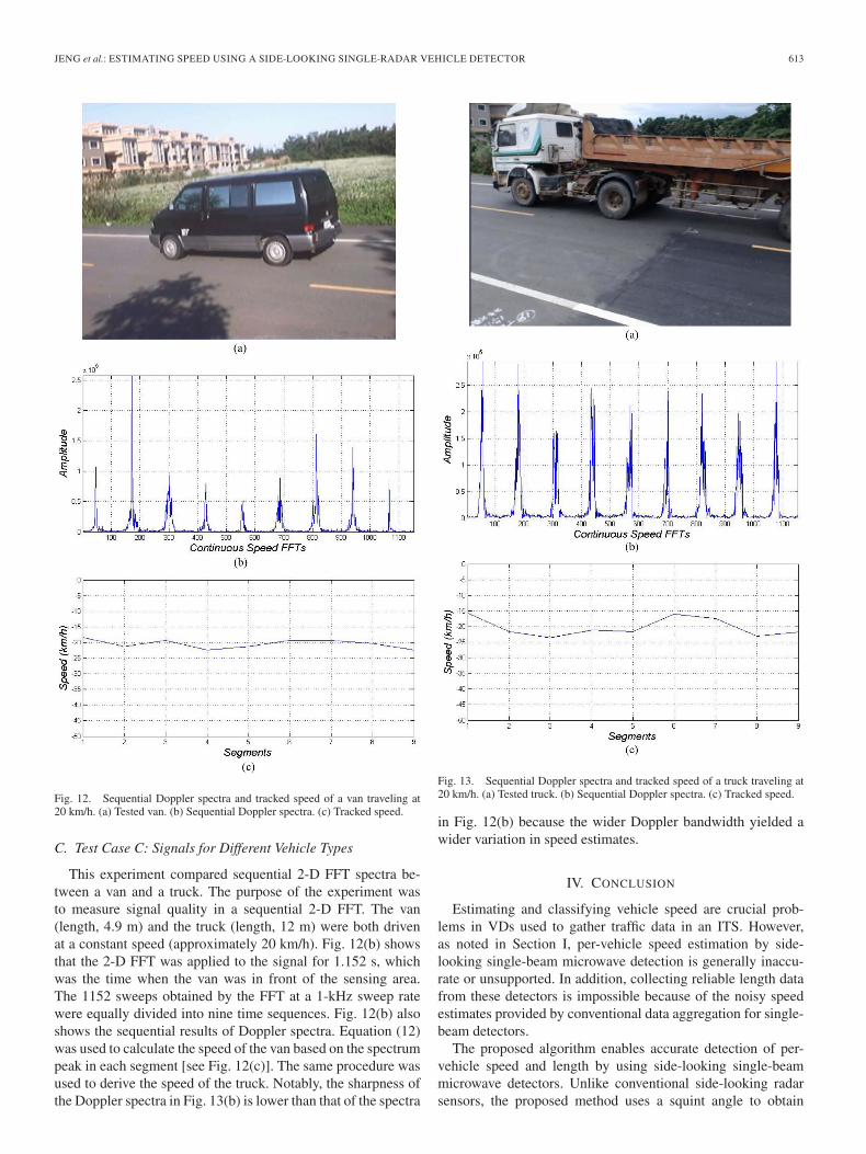
Fig. 12. Sequential Doppler spectra and tracked speed of a van traveling at20 km/h. (a) Tested van. (b) Sequential Doppler spectra. (c) Tracked speed.
C. Test Case C: Signals for Different Vehicle Types
This experiment compared sequential 2-D FFT spectra be-tween a van and a truck. The purpose of the experiment wasto measure signal quality in a sequential 2-D FFT. The van(length, 4.9 m) and the truck (length, 12 m) were both drivenat a constant speed (approximately 20 km/h). Fig. 12(b) showsthat the 2-D FFT was applied to the signal for 1.152 s, whichwas the time when the van was in front of the sensing area.The 1152 sweeps obtained by the FFT at a 1-kHz sweep ratewere equally divided into nine time sequences. Fig. 12(b) alsoshows the sequential results of Doppler spectra. Equation (12)was used to calculate the speed of the van based on the spectrumpeak in each segment [see Fig. 12(c)]. The same procedure wasused to derive the speed of the truck. Notably, the sharpness ofthe Doppler spectra in Fig. 13(b) is lower than that of the spectra
Fig. 13. Sequential Doppler spectra and tracked speed of a truck traveling at20 km/h. (a) Tested truck. (b) Sequential Doppler spectra. (c) Tracked speed.
in Fig. 12(b) because the wider Doppler bandwidth yielded awider variation in speed estimates.
IV. CONCLUSION
Estimating and classifying vehicle speed are crucial prob-lems in VDs used to gather traffic data in an ITS. However,as noted in Section I, per-vehicle speed estimation by side-looking single-beam microwave detection is generally inaccu-rate or unsupported. In addition, collecting reliable length datafrom these detectors is impossible because of the noisy speedestimates provided by conventional data aggregation for single-beam detectors.
The proposed algorithm enables accurate detection of per-vehicle speed and length by using side-looking single-beammicrowave detectors. Unlike conventional side-looking radarsensors, the proposed method uses a squint angle to obtain
614 IEEE TRANSACTIONS ON INTELLIGENT TRANSPORTATION SYSTEMS, VOL. 15, NO. 2, APRIL 2014
stronger Doppler signals compared with conventional sensors.Since the proposed scheme couples speed and range measure-ments for the lane in which a vehicle is moving, estimates of ve-hicle location and movement are unambiguous and reliable. Thedirections of moving vehicles are also determined according tonegative- or positive-displacement Doppler shifts, regardless ofthe driving lane. The length of a vehicle can be also derivedfrom its speed and the duration of time in the sensing zone.Therefore, a single radar can efficiently measure speed andmonitor all lanes of a traffic route.
Simulations confirmed that the theoretical range-DopplerFMCW principle derived in this study can be used to detectmultiple vehicles simultaneously. A commercially available10.6-GHz radar and modified signal processing software wereused for experimental tests. The experimental results showthat the proposed algorithm is highly accurate, particularly atlow speeds. The measurement error was less than 4 km/h. Inaddition to detecting vehicles, the experiments showed that theproposed method can detect weak moving targets, such as bikesand pedestrians.
Although the proposed algorithm exhibited acceptable perfor-mance at low speeds, further studies are needed to increase theapplicable vehicle speed range for the algorithm. Reducing thesquint angle can reduce radial speed but would also weakenthe Doppler signal and speed resolution. The solution is usinga DSP with higher performance capability to improve therobustness and accuracy of the proposed algorithm.
ACKNOWLEDGMENT
The authors would like to thank U&U Engineering, Inc. forsupporting VDs and facilities to accomplish the experimentalwork and C.-M. Yang, H.-J. Hsu, and C.-Y. Hsu for implement-ing the experiments.
REFERENCES
[1] I. S. Kim, K. Jeong, and J. K. Jeong, “Two novel radar vehicle detectorsfor the replacement of a conventional loop detector,” Microw. J., vol. 44,no. 7, pp. 22–69, 2001.
[2] Y. H. Wang and N. L. Nihan, “Can single-loop detectors do the workof dual-loop detectors?” J. Transp. Eng., vol. 129, no. 2, pp. 169–176,Mar. 2003.
[3] B. Coifman, S. Dhoorjaty, and Z. H. Lee, “Estimating median velocity in-stead of mean velocity at single loop detectors,” Transp. Res. C, EmergingTechnol., vol. 11, no. 3/4, pp. 211–222, Jun.–Aug. 2003.
[4] B. Coifman and S. B. Kim, “Speed estimation and length based vehicleclassification from freeway single-loop detectors,” Transp. Res. C, Emerg-ing Technol., vol. 17, no. 4, pp. 349–364, Aug. 2009.
[5] S. J. Park, T. Y. Kim, S. M. Kang, and K. H. Koo, “A novel signalprocessing technique for vehicle detection radar,” in Proc. IEEE MTT-SInt. Microw. Symp. Dig., Philadelphia, PA, USA, Jun. 2003, vol. 1,pp. 607–610.
[6] P. J. Wang, C. M. Li, C. Y. Wu, and H. J. Li, “A channel awareness vehicledetector,” IEEE Trans. Intell. Transp. Syst., vol. 11, no. 2, pp. 339–347,Jun. 2010.
[7] H. Rohling, “Some radar topics: Waveform design, range CFAR ANDtarget recognition,” in Advances in Sensing with Security Applications.New York, NY, USA: Springer-Verlag, 2006, pp. 293–322.
[8] I. Urazghildiiev, R. Ragnarsson, and A. Rydberg, “High-resolution esti-mation of ranges using multiple-frequency CW radar,” IEEE Trans. Intell.Transp. Syst., vol. 8, no. 2, pp. 332–339, Jun. 2007.
[9] M. Skolnik, Introduction to Radar Systems., 3rd ed. Boston, MA, USA:McGraw-Hill, 2001.
[10] A. G. Stove, “Linear FMCW radar techniques,” Proc. Inst. Elect. Eng.–F,Radar Signal Process., vol. 139, no. 5, pp. 343–350, Oct. 1992.
[11] A. Wojtkiewicz, J. Misiurewicz, M. Nałecz, K. Jedrzejewski, andK. Kulpa, “Two-dimensional signal processing in FMCW radars,” in Proc.XX KKTOiUE, Kołobrzeg, Poland, 1997, pp. 475–480.
[12] M. Vossiek, T. vonKerssenbrock, and P. Heide, “Signal processing meth-ods for millimetrewave FMCW radar with high distance and Dopplerresolution,” in Proc. 27th Eur. Microw. Conf., 1997, pp. 1127–1132.
[13] A. Meta, P. Hoogeboom, and L. P. Ligthart, “Signal processing for FMCWSAR,” IEEE Trans. Geosci. Remote Sens., vol. 45, no. 11, pp. 3519–3532,Nov. 2007.
[14] P. Marques and J. Dias, “Velocity estimation of fast moving targets usinga single SAR sensor,” IEEE Trans. Aerosp. Electron. Syst., vol. 41, no. 1,pp. 75–89, Jan. 2005.
[15] N. Weber, S. Moedl, and M. Hackner, “A novel signal processing approachfor microwave Doppler speed sensing,” in Proc. IEEE MTT-s Int. Microw.Symp., 2002, pp. 2233–2236.
[16] C. F. Huang, H. P. Lu, and W. H. Chieng, “Estimation of single-tone signalfrequency with the special reference to frequency-modulated continuouswave system,” Meas. Sci. Technol., vol. 23, no. 3, pp. 35 002–35 012,Mar. 2012.
Shyr-Long Jeng was born in Taiwan in 1965. Hereceived the Ph.D. degree in mechanical engineer-ing from National Chiao Tung University, Hsinchu,Taiwan, in 1996.
From 1996 to 1998, he was with an electricalmotor design company. He is currently an Asso-ciate Professor with the Department of Electricaland Electronic Engineering, Ta Hwa University ofScience and Technology, Hsinchu. His research in-terest includes microprocessor-based control andapplications.
Wei-Hua Chieng was born in Taiwan in 1959. Hereceived the B.S. degree in mechanical engineer-ing from National Tsing Hua University, Hsinchu,Taiwan, in 1982 and the M.S. degrees in mechan-ical engineering and in electrical engineering andthe Ph.D. degree in mechanical engineering fromColumbia University, New York, NY, USA, in 1986,1987, and 1989, respectively.
From 1987 to 1989, he was awarded an IBMManufacturing Fellowship. He is currently a Profes-sor with the Department of Mechanical Engineering,
National Chiao Tung University, Hsinchu. His research interests include auto-mated control, mechatronics, and microelectromechanical systems.
Hsiang-Pin Lu was born in Taiwan in 1966. Hereceived the B.S. degree in computer science fromChung Cheng Institute of Technology, Taoyuan,Taiwan, in 1988 and the M.S. degree in computingfrom Imperial College London, London, U.K., in1996.
He is currently a Research Assistant with NationalChiao Tung University, Hsinchu, Taiwan. From1988 to 2006, he was a Researcher with Chung-Shan Institute of Science and Technology, Taoyuan.His research interests include signal processing in
frequency-modulated continuous-wave sensors, music cognition, and algorith-mic composition.


![IEEETRANSACTIONS ON INTELLIGENT TRANSPORTATION …cvrr.ucsd.edu/publications/2014/SivaramanTrivedi_IEEETITS2014.pdfThe belief mass approach is used in [12] for occupancy grid computation](https://img.pdfslide.us/doc/110x75/6128957e6602e56df018ee20/ieeetransactions-on-intelligent-transportation-cvrrucsdedupublications2014sivaramantrivedi.jpg)