Embed Size (px)
Citation preview

This article has been accepted for inclusion in a future issue of this journal. Content is final as presented, with the exception of pagination.
IEEE/ACM TRANSACTIONS ON NETWORKING 1
CEDAR: A Low-Latency and Distributed Strategyfor Packet Recovery in Wireless Networks
Chenxi Qiu, Haiying Shen, Senior Member, IEEE, Member, ACM, Sohraab Soltani, Karan Sapra, Hao Jiang, andJason O. Hallstrom, Member, IEEE
Abstract—Underlying link-layer protocols of well-establishedwireless networks that use the conventional “store-and-forward”design paradigm cannot provide highly sustainable reliability andstability in wireless communication, which introduce significantbarriers and setbacks in scalability and deployments of wirelessnetworks. In this paper, we propose a Code Embedded DistributedAdaptive and Reliable (CEDAR) link-layer framework that tar-gets low latency and balancing en/decoding load among nodes.CEDAR is the first comprehensive theoretical framework for an-alyzing and designing distributed and adaptive error recovery forwireless networks. It employs a theoretically sound framework forembedding channel codes in each packet and performs the errorcorrecting process in selected intermediate nodes in a packet’sroute. To identify the intermediate nodes for the decoding, wemathematically calculate the average packet delay and formalizethe problem as a nonlinear integer programming problem. Byminimizing the delays, we derive three propositions that: 1) canidentify the intermediate nodes that minimize the propagationand transmission delay of a packet; and 2) and 3) can identifythe intermediate nodes that simultaneously minimize the queuingdelay and maximize the fairness of en/decoding load of all thenodes. Guided by the propositions, we then propose a scalable anddistributed scheme in CEDAR to choose the intermediate en/de-coding nodes in a route to achieve its objective. The results fromreal-world testbed “NESTbed” and simulation with MATLABprove that CEDAR is superior to schemes using hop-by-hopdecoding and destination decoding not only in packet delay andthroughput but also in energy-consumption and load distributionbalance.
Index Terms—Link-layer protocol, low-latency, reliability andstability, wireless networks.
I. INTRODUCTION
D ESPITE the unprecedented success and proliferation ofwireless communication, there are major shortcomings in
the underlying link-layer protocols in providing sustainable re-liability and stability among wireless users. Popular wirelesslink-layer protocols, such as the retransmission ARQ or for-ward error correction (FEC)-based ARQ (HARQ) approaches(employed by the IEEE 802.xx and LTE standard suite) are
Manuscript received January 17, 2013; revised September 05, 2013 and April09, 2014; accepted June 18, 2014; approved by IEEE/ACM TRANSACTIONS ONNETWORKING Editor L. Qiu. (Corresponding author: Haiying Shen.)C. Qiu, H. Shen, and K. Sapra are with the Department of Electrical and
Computer Engineering, Clemson University, Clemson, SC 29634 USA (e-mail:[email protected]; [email protected]; [email protected]).S. Soltani is with Intelligent Automation, Inc., Rockville, MD 20855 USA
(e-mail: [email protected]).H. Jiang and J. O. Hallstrom are with the School of Computing, Clemson
University, Clemson, SC 29634 USA (e-mail: [email protected];[email protected]).Color versions of one or more of the figures in this paper are available online
at http://ieeexplore.ieee.org.Digital Object Identifier 10.1109/TNET.2014.2332980
designed to achieve some level of reliability by discarding acorrupted packet at the receiver and performing one or moreretransmissions until the packet is decoded/received error-freeor a maximum number of retransmission attempts is reached.This methodology suffers from degradation of throughput andoverall system instability since decoding failures at the receiverdue to a small number of bit errors lead to packet drops and dis-carding a large number of correctly delivered data bits.Many leading research efforts [1]–[12] have highlighted the
inefficiencies of these link-layer protocols and proposed a va-riety of remedy solutions. The majority of these efforts eitherconsider variations of the ARQ, HARQ, or a hybrid approachof both schemes [1], [5], [9], [11]–[13]. They largely followthe traditional “store-and-forward” link-layer design paradigm:Each data packet must be fully received and corrected by everyrelay node before it is forwarded. This design paradigm in-creases stability, but still cannot provide high stability due toits hop-by-hop operation.It is our belief that achieving the ultimate objective of the de-
velopment of ubiquitous and heterogeneous wireless networksdemands fundamental and radical changes to the conventionallink-layer protocol design. Thus, we study and develop alter-native optimal and low-complexity error recovery strategies inlink-layer design to achieve high reliability and stability by par-tially and optimally selecting relay nodes. The objectives of thestrategies are to ensure: 1) low end-to-end latency and rapid de-livery of packets; 2) high throughput with minimum data loss.To meet these objectives, we develop solutions that address thefollowing key issues: 1) minimizing propagation and transmis-sion (prop&tran) delay: At which intermediate nodes (if any)should a link-layer packet be detected tominimize packet delay?2) minimizing queuing delay: As multiple relay nodes in a routeperform error recovery on the same packet stream and one nodemay perform error recovery for multiple packet streams, howshould we select relay nodes that provide global reliability andstability in a wireless network with many source–destinationpacket streams? 3) energy-efficiency: what is the optimal pro-cessing contribution of each relay node for error recovery withrespect to reliability and energy consumption? Note that ourwork shares the same objectives as some previous works onen/decoding schemes and network coding (e.g., PPR [9] andMIXIT [12]). However, unlike these previous works that focuson route determination or en/decoding scheme design, our workaims to determine the intermediate nodes to en/decode packetsgiven a route and an en/decoding scheme. Our work can beemployed in those en/decoding schemes and network codingschemes for further performance enhancement.The design of the strategies requires network-of-queues
models that capture the error correction process and networking
1063-6692 © 2014 IEEE. Personal use is permitted, but republication/redistribution requires IEEE permission.See http://www.ieee.org/publications_standards/publications/rights/index.html for more information.
This article has been accepted for inclusion in a future issue of this journal. Content is final as presented, with the exception of pagination.
2 IEEE/ACM TRANSACTIONS ON NETWORKING
effects of traffic flows over multihop wireless paths. Accord-ingly, we develop mathematical models for the prop&trandelay and queuing delay for a packet based on the path lengthbetween two consecutive decoding nodes in a route (routesegment length). Through rigorous mathematical analysis onthe models, we derive two propositions that: 1) can identifythe intermediate nodes for decoding that minimize prop&trandelay of a packet; and 2) prove that balanced en/decoding loaddistribution among decoding nodes in the network minimizesthe queuing delay. Based on the propositions, we formulatethe problem of minimizing delay as a nonlinear integer pro-gramming problem. However, due to the NP-hard nature ofthe problem and impracticability of collecting all requiredinformation to find the global optimal solution, we proposea suboptimal Code Embedded Distributed Adaptive and Re-liable (CEDAR) link-layer framework for wireless networks.CEDAR is a distributed and cooperative error recovery de-sign, which represents a new paradigm in both transmissionand distributed recovery processing and promises significantincrease of capacity and throughput gain in wireless networks.CEDAR provides an adaptive environment for various errorrecovery strategies with respect to reliability, stability, andenergy consumption constraints. We believe CEDAR is thefirst comprehensive theoretical framework for analyzing anddesigning distributed and adaptive link-layer error recoverythat targets system reliability, stability in conjunction withoptimal energy consumption for wireless communication.We summarize our contributions as follows. 1) We build a
model for the probability of decoding failure of a packet trav-eling through a given number of hops based on the finite-stateMarkovian channel (FSMC) model. 2) We build rigid mathe-matical models for the prop&tran delay, and queuing delay fora packet, and en/decoding load of each node. 3) We formalizethe problem of choosing the intermediate en/decoding nodes forminimum delay and minimum difference of en/decoding load ofall the nodes as a nonlinear integer programming problem thatis an NP-hard problem. 4) We propose a distributed suboptimalstrategy for CEDAR that achieves high reliability, stability, anden/decoding load balancing.The reminder of the paper is organized as follows. Section II
states the problem that needs to be solved tominimize the packetdelay. Section III introduces a mathematical model that formal-izes the problem as a nonlinear integer programming problemand derives two propositions to minimize the delay. Guidedby the propositions, Section IV details the design of CEDARfor solving the problem in Section II, and Section V presentsperformance evaluation of CEDAR in comparison to previousschemes. Section VI presents a review of the related works. Thefinal section concludes with a summary of contributions and adiscussion on future work.
II. PROBLEM STATEMENT
Consider a wireless network composed of nodes denotedby . Each traffic flow from a source node toa destination node transverses over a predetermined set of links(a route specified by the network layer). Letdenote the set of transmission routes. Each routecarries a data stream following Poisson distribution with arrivalrate . We use to represent the node se-quence in ( ), where is the number of
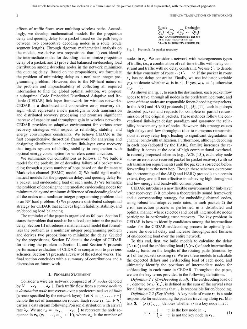
Fig. 1. Protocols for packet recovery.
nodes in . We consider a network with heterogeneous typesof traffic, i.e., a combination of real-time traffic with delay con-straint and traffic with no delay constraint. We use to denotethe delay constraint of route ; if the packet in routehas no delay constraint. Finally, we use indicator variableto denote whether is in . If yes, ; otherwise
.As shown in Fig. 1, to reach the destination, each packet flow
needs to travel through all nodes in the predetermined route, andsome of these nodes are responsible for en/decoding the packets.In the ARQ and HARQ protocols [1], [5], [11], each hop dropsdistorted packets and requests for complete or partial retrans-mission of the original packets. These methods follow the con-ventional link-layer design paradigm and guarantee the relia-bility between any pair of nodes. However, this strategy causeshigh delays and low throughput (due to numerous retransmis-sions at every relay hop), leading to significant degradation inchannel bandwidth utilization. Furthermore, although decodingin each hop (adopted by the HARQ family) increases the re-liability, it comes at the cost of high computational overhead.In recently proposed schemes (e.g., ACE [15]), each relay nodestores an erroneous received packet for packet recovery (with noretransmission requirements) until the packet is corrected beforeforwarding it to the next hop. Though these schemes overcomethe shortcomings of the ARQ and HARQ protocols to a certainextent, they are still not effective in achieving high throughputand low energy and bandwidth consumption.CEDAR introduces a new flexible environment for link-layer
error recovery: 1) it employs a theoretically sound frameworkand a corresponding strategy for embedding channel codes,using robust and adaptive code rates, in each packet; 2) theerror correction process is performed in a distributed andoptimal manner where selected (and not all) intermediate nodesparticipate in performing error recovery. The key problem inCEDAR is how to identify candidates among the intermediatenodes for the CEDAR en/decoding process to optimally de-crease the overall delay and increase throughput and fairnessof en/decoding load over the entire network.To this end, first, we build models to calculate the delay
( ) and the en/decoding load ( ) of each intermediatenode based on the lengths of the routing paths (denoted by) of the packets crossing . We use these models to calculate
the expected delays and en/decoding load of each node, andultimately identify the positions of intermediate nodes foren/decoding in each route in CEDAR. Throughout the paper,we use the key terms provided in the following definitions.Definition 2.1 (En/Decoding load): The en/decoding load of, denoted by , is defined as the sum of the arrival rates
for all the packet streams that is responsible for en/decoding.Definition 2.2 (Key Node): A key node of route is a node
responsible for en/decoding the packets traveling along . Ma-trix denotes whether is a key node in :
is the key node inis not the key node in .
(1)

This article has been accepted for inclusion in a future issue of this journal. Content is final as presented, with the exception of pagination.
QIU et al.: CEDAR: LOW-LATENCY AND DISTRIBUTED STRATEGY FOR PACKET RECOVERY IN WIRELESS NETWORKS 3
Fig. 2. Route segment.
Definition 2.3 (Route Segment): A route segment of is asection of the end-to-end path between one key node to eitherthe endpoints or another key node. The length of a route segmentis defined as the number of hops in the route segment.In each route segment, the packet sender (the first key node)
encodes the packets, and the packet receiver (the second keynode) decodes the packets. In other words, the second key nodeis responsible for decoding for its route segment. Use matrix
to denote the length of a route segment withdecoding node in , and use vector denote the lengthsof route segments responsible by for all the routes, i.e.,
and . Here, we defineif has no responsibility of decoding the packet in .
For example, in Fig. 2, there are eight nodes ,and three routes , where ,
, and . , , andare the key nodes in ; , , and are the key nodes
in ; , , and are the key nodes in . Then, we canderive that and because there are one hopfrom to in and three hops from to in . Also,
because is not responsible for decoding packets in. Hence, .Let denote the arrival rate of the data stream that is
responsible for en/decoding in . Then,We use to denote the average delay when a packetcrosses with route segment vector . Then, the total av-erage packet delay decoding at within a unit time equals
. Also, we use to represent the av-erage en/decoding load of and use to representthe average en/decoding load of all the nodes in . Then,
.Objective: The objectives of CEDAR are: 1) to minimize the
total delay of the packets in the entire system, which can berepresented as
(2)
and 2) to balance the en/decoding load of all the nodes in thenetwork. In this paper, we use standard deviation [14] of en/de-coding loads, which reflects how much variation exists betweeneach node’s en/decoding load and , tomeasure the balanceof the en/decoding load of the network. The lower the value ofthe standard deviation, the higher the fairness of the en/decodingload of all the nodes. Then, the objective can be formulated as
(3)
Consequently, we combine these two objectives and formulatethe optimization problem as
s.t. (4)
where and represent the weights we set for these twoobjectives. In this paper, we primarily consider minimizingpacket delay and secondarily consider balancing en/decodingload. Thus, we set in our system.Now, we need to consider how to solve the multiple objective
optimization problem: The packet delay in (which is com-posed of prop&tran and queueing delays) is a function of .This will be deduced in the mathematical analysis in Section III.We use to denote the average prop&tran delay of allthe packet streams being decoded in , and use to de-note the average queuing delay of the packet stream in . Then,the total average delay when one packet crosses is
(5)
Thus, we need to minimize and in orderto achieve the objective of CEDAR in (4). To this end, inSections III-A and III-B, we model the bit error rate (BER)fluctuations of wireless channels and probability of successfuldecoding. Sections III-C and III-D use this model to formulatethe prop&tran delay and the queuing delay .Finally, Section III-E derives two propositions to minimize
and , respectively. Guided by the proposi-tions, we design CEDAR in Section IV.
III. MATHEMATICAL MODELING
In this section, we first present a Markovian wireless channelmodel to capture the variations in wireless error conditions dueto nonstationary wireless noise and calculate BER of a packetwhen it goes through several channels. Using this model, weanalyze the relationship between the number of hops a packetcrosses and the probability of its successful decoding. This re-lationship leads us to calculate the prop&tran delay and queuingdelay, respectively. By minimizing the two delays, we can findthe locations of intermediate nodes in a route for decoding. Fi-nally, we formulate the problem of minimizing the sum of thedelays as a nonlinear integer programming problem. The analyt-ical results and the formed problem lay the foundation for thedesign of an optimized strategy for choosing intermediate nodesfor the CEDAR packet recovery.
A. Markovian Channel Model
FSMC model [15] is a channel model that uses finite-stateMarkov chain to describe the process, under which errors areintroduced into a transmitted packet over a wireless route. Themodel has a finite set of error states (), each corresponding to a binary symmetric channel (BSC).
The channel model can be considered as a combination ofnumber of various BSCs with unique BERs ( ) (i.e.,for , ). Assume packets are transmittedduring discrete time-slots ( ) that can be re-ferred to as transmission intervals. During the th transmissioninterval, a packet is transmitted from a BSC to another BSCwithcrossover BER . Each of a particular is valued from .The Markovian model assumes a homogenous and stationaryMarkov chain with transition probability matrixand initial probability . can betrained on real channel traces by using the statistics of previoustransmission intervals. This captures the effects of multipath
This article has been accepted for inclusion in a future issue of this journal. Content is final as presented, with the exception of pagination.
4 IEEE/ACM TRANSACTIONS ON NETWORKING
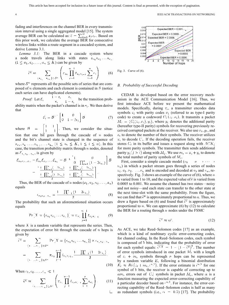
fading and interferences on the channel BER in every transmis-sion interval using a single aggregated model [15]. The systemaverage BER can be calculated as: . Based onthis prior work, we calculate the average BER for consecutivewireless links within a route segment in a cascaded system, andderive Lemma 3.1.Lemma 3.1: The BER in a cascade system where
a node travels along links with states( ) can be given by
(6)
where represents all the possible sets of series that are com-posed of elements and each element is contained in (noticeeach series can have duplicated elements).
Proof: Let be the transition prob-
ability matrix when the packet’s channel is in . We then derivethat
(7)
where . Then, we consider the situa-
tion that one bit goes through the cascade of nodesand the bit’s channel state is changed in the sequence of
, . In thiscase, the transition probability matrix through nodes, denotedas , is given by
Thus, the BER of the cascade of nodes ( )equals
(8)
The probability that such an aforementioned situation occursequals
(9)
where is a random variable that represents the series. Then,the expectation of error bit through the cascade of hops isgiven by
(10)
When
(11)
Fig. 3. Curve of (6).
B. Probability of Successful Decoding
CEDAR is developed based on the error recovery mech-anism in the ACE Communication Model [16]. Thus, wefirst introduce ACE before we present the mathematicalmodels. Specifically, during , a transmitter encodes datasymbols with parity codes (referred to as type-I paritycode) to create a codeword . It transmits a packet
, where denotes the additional parity(hereafter type-II parity) symbols for recovering previously re-ceived corrupted packets at the receiver. We also use , , andto denote the number of their symbols. The receiver utilizesto decode . If the decoding operation fails, the receiver
stores in its buffer and issues a request along withfor more parity symbols. The transmitter then sends additionalparity along with . We use to denotethe total number of parity symbols of .First, consider a simple cascade model () in which a packet stream goes through a series of nodes
and is encoded and decoded at and , re-spectively. Fig. 3 shows an example of the curve of (6), whereis varied from 1 to 10, and the expected value of is varied from0.0005 to 0.001. We assume the channel has two states—noisyand not noisy—and each state can transfer to the other state atthe next time-slot with the same probability. From the figure,we can find that is approximately proportional to . Thus, wedrew a figure based on (6) and found that is approximatelyproportional to . We can approximate (6) by (12) to calculatethe BER for a routing through nodes under the FSMC
(12)
As ACE, we take Reed–Solomon codes [17] as an example,which is a kind of nonbinary cyclic error-correcting codes,for channel coding. In the Reed–Solomon codes, each symbolis composed of bits, indicating that the probability of errorfor each symbol equals: . The numberof error symbols introduced in one packet with a lengthof symbols through hops can be representedby a random variable following a binomial distribution
. If the error estimate is for onesymbol of bits, the receiver is capable of correcting up to
errors out of symbols in packet , where is afunction measuring the expected error-correcting capability ofa particular decoder based on . For instance, the error-cor-recting capability of the Reed–Solomon codes is half as manyas redundant symbols (i.e., ) [17]. The probability

This article has been accepted for inclusion in a future issue of this journal. Content is final as presented, with the exception of pagination.
QIU et al.: CEDAR: LOW-LATENCY AND DISTRIBUTED STRATEGY FOR PACKET RECOVERY IN WIRELESS NETWORKS 5
Fig. 4. Transmission and propagation delay.
of successfully recovering data bits by a parity code withlength symbols equals
(13)From (13), we observe that the probability of successful is adiscrete function of two variables
(14)
is monotonically decreasing function of (numberof hops in a route) and is a monotonically increasing functionof (number of symbols in parity code).Based on (14), the number of times (i.e., trials) a packet is
required to be decoded until it is recovered has a nonhomoge-neous geometric distribution (denoted by ) [18] given that thelength (i.e., number of symbols) of predetermined parity codeequals at the th trial.Lemma 3.2: We use to denote the probability of
successful decoding on the th decoding trial for a packetgoing through hops. Then
(15)
C. Propagation and Transmission Delay
In this section, we consider the prop&tran delay of eachpacket . We use to denote the prop&tran delay ofwhen the parity code of has been transmitted for times
through nodes. Let represent the propagation delayfor one packet going through nodes and denotethe transmission delay of the ACK packet. Furthermore, let
denote the transmission delay of the packet . Thelength of this packet is , where is the thpacket that carries ’s parity symbols for the th time after
times of recovery failures (i.e., type-II parities). Then, asFig. 4 shows, can be calculated as
(16)
We use to denote the bandwidth provided to the routetravels in the th hop. Assume electric signal travels at velocityin the media and the distance of each hop ( ) is an invariable.Then, , , and can be calculated as
(17)
Fig. 5. Route segment.
Based on (16) and (17), we can derive that
(18)Based on (15) in Lemma 3.2 and (18), we retrieve Lemma 3.3for the expectation of .Lemma 3.3: Assuming each packet has the same length,
the expected propagation and transmission delay of a packetcan be calculated by
(19)
As shown in Fig. 5, given a route from a source node to a desti-nation node, we can divide the route into segments, each seg-ment having length of . In each route segment,a packet is encoded at the first node and decoded at the lastnode. The goal of our scheme is to determine thein order to minimize the prop&tran delay of a packet from thesource to the destination, i.e., to achieve
s.t.
Note that the above formulated optimization problem still holdswith routing delay constraint since minimizing issufficient for satisfying the delay constraint. That is, if the min-imum value of is no larger than the constraint, thenthe constraint is always satisfied; otherwise, there is no solutionto satisfy the constraint.Error Estimation Code: Recall that in the above method, a
receiver requests its sender to send the packet repetitively untilit can successfully decode the packet, which may lead to mul-tiple retransmissions for each packet. In order to avoid such re-transmissions, we introduce another method that only needs oneretransmission.In this method, after receiving a packet, each receiver first
uses error estimation code (EEC) [19] to estimate the numberof corrupted symbols in the received packet, and then sends arequest to its sender to ask for the additional parity code, whichhelps successfully recover the packet.EEC estimates BER (e.g., checks whether BER is no larger
than 1%) of the received packet, but in CEDAR, the receiverneeds to estimate the number of corrupted symbols. Then,CEDAR uniformly samples the symbols instead of bits andbuilds EEC for the sampled symbols. More specifically, for apacket with length , there are levels of EEC bitsadded in each packet, with EEC bits in each level. An EEC bit
This article has been accepted for inclusion in a future issue of this journal. Content is final as presented, with the exception of pagination.
6 IEEE/ACM TRANSACTIONS ON NETWORKING
at level is simply the parity bit forrandomly chosen symbols in the packet, which has totally
bits. Each of these data symbols is chosenuniformly randomly and independently (with replacement)from the original symbols.In addition to the parity code, each packet also contains
EEC codes, which has a length of . Note thatthough this EEC-based method reduces the number of retrans-mission, it increases the transmission packet size. First, weconsider an ideal scenario, in which EEC never underestimatesthe number of corrupted symbols for each packet. Then, theprop&tran delay of a packet can be simply calculated by
(20)
However, like any error estimator, EEC may underestimate thenumber of errors. We use to denote the probability of underes-timation, then the actual expected prop&tran delay of a packet
is given by
(21)where
and .
D. Queuing Delay
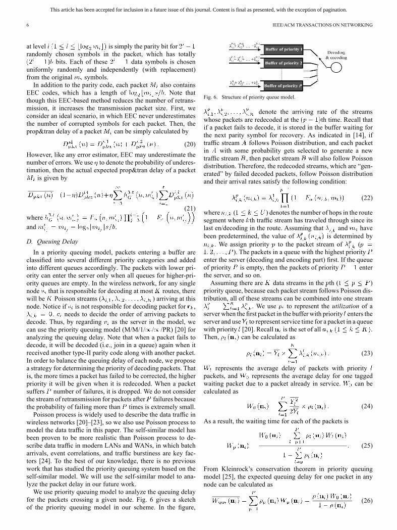
In a priority queuing model, packets entering a buffer areclassified into several different priority categories and addedinto different queues accordingly. The packets with lower pri-ority can enter the server only when all queues for higher-pri-ority queues are empty. In the wireless network, for any singlenode that is responsible for decoding at most routes, therewill be Poisson streams ( ) arriving at thisnode. Notice if is not responsible for decoding packet for ,
. needs to decide the order of arriving packets todecode. Thus, by regarding as the server in the model, wecan use the priority queuing model (M/M/1/ / /PR) [20] foranalyzing the queuing delay. Note that when a packet fails todecode, it will be decoded (i.e., join in a queue) again when itreceived another type-II parity code along with another packet.In order to balance the queuing delay of each node, we proposea strategy for determining the priority of decoding packets. Thatis, the more times a packet has failed to be corrected, the higherpriority it will be given when it is redecoded. When a packetsuffers number of failures, it is dropped. We do not considerthe stream of retransmission for packets after failures becausethe probability of failing more than times is extremely small.Poisson process is widely used to describe the data traffic in
wireless networks [20]–[23], so we also use Poisson process tomodel the data traffic in this paper. The self-similar model hasbeen proven to be more realistic than Poisson process to de-scribe data traffic in modern LANs and WANs, in which batcharrivals, event correlations, and traffic burstiness are key fac-tors [24]. To the best of our knowledge, there is no previouswork that has studied the priority queuing system based on theself-similar model. We will use the self-similar model to ana-lyze the packet delay in our future work.We use priority queuing model to analyze the queuing delay
for the packets crossing a given node. Fig. 6 gives a sketchof the priority queuing model in our scheme. In the figure,
Fig. 6. Structure of priority queue model.
denote the arriving rate of the streamswhose packets are redecoded at the th time. Recall thatif a packet fails to decode, it is stored in the buffer waiting forthe next parity symbol for recovery. As indicated in [14], iftraffic stream follows Poisson distribution, and each packetin with some probability gets selected to generate a newtraffic stream , then packet stream will also follow Poissondistribution. Therefore, the redecoded streams, which are “gen-erated” by failed decoded packets, follow Poisson distributionand their arrival rates satisfy the following condition:
(22)
where ( ) denotes the number of hops in the routesegment where th traffic stream has traveled through since itslast en/decoding in the route. Assuming that and havebeen predetermined, the value of is determined by
. We assign priority to the packet stream of (). The packets in a queue with the highest priority
enter the server (decoding and encoding part) first. If the queueof priority is empty, then the packets of priority enterthe server, and so on.Assuming there are data streams in the th ( )
priority queue, because each packet stream follows Poisson dis-tribution, all of these streams can be combined into one stream
. We use to represent the utilization of aserver when the first packet in the buffer with priority enters theserver and use to represent service time for a packet in a queuewith priority [20]. Recall is the set of all .Then, can be calculated as
(23)
represents the average delay of packets with prioritypackets, and represents the average delay for one taggedwaiting packet due to a packet already in service. can becalculated as
(24)
As a result, the waiting time for each of the packets is
(25)
From Kleinrock’s conservation theorem in priority queuingmodel [25], the expected queuing delay for one packet in anynode can be calculated as
(26)

This article has been accepted for inclusion in a future issue of this journal. Content is final as presented, with the exception of pagination.
QIU et al.: CEDAR: LOW-LATENCY AND DISTRIBUTED STRATEGY FOR PACKET RECOVERY IN WIRELESS NETWORKS 7
where
(27)
Now, we consider the queueing delay for one packet, whichmight enter the queueing system several times due to re-en/de-coding. During time interval ( is large enough), the totalnumber of packets that enter the queueing system equals
(28)
The total waiting time can be given by
(29)
Lemma 3.4: The expectation of the total queuingtime for one packet when it goes through a node with
can be calculated as
(30)
If each receiver uses EEC to estimate the number of corruptedsymbols, then the packet only needs to be retransmitted at mosttwice, i.e., . Hence, the expectation of the total queuingtime equals
(31)
The above priority queue model assumes that packets have nodelay constraints, so it gives a higher priority to a packet that hasbeen retransmitted more times. With the consideration of packetdelay constraints (deadlines), we can first give a higher priorityto the packet with smaller remaining time period to its deadline;if two packets have the same remaining time periods, we givea higher priority to the packet that has been transmitted moretimes. Modeling such a two-level priority queue to calculatequeuing delay is nontrivial, so we leave this task as our futurework.
E. Minimizing the Delays
As shown in Section II, we need to minimize andin order to achieve the objective of CEDAR in (4).
According to (19), the prop&tran delay of the packet stream forin is calculated as
(32)
Consequently, the average prop&tran delay of all the packetstream decoded in is calculated as
(33)
where . The average queuing delay ofthe packet stream in can be derived from (30)
(34)
By minimizing the above and , we retrievetwo propositions presented below.1) Minimizing Queuing Delay:Proposition 3.1: Suppose and
with total arrival rate , eachpacket is required to be decoded once in its route, and each nodecan decode the packet in any route, and also. To minimize the total queueing delay for all the packets,
the packet rate each node is responsible for should be the same.That is
(35)
Proof: According to (23), (24), (26), and (27), the queuingdelay of packets decoded at can be derived as
(36)
where and are invariants figured by (27), (23), and (22).Then, the following equation can be derived:
(37)
Let , and then . Accordingto Cauchy–Schwarz inequality [14], we find that
(38)
(39)
from which, we can derive that
(40)
and
(41)
which reaches its minimum value when, or the values of are equal
to each other.According to Proposition 3.1, given several packet streams
and number of nodes required to decode these packets, we needto balance the en/decoding load for all of these nodes. For ex-ample, in Fig. 7, three packet streams , , and are trans-mitted through the 1st route, the 2nd route and the 3rd route,
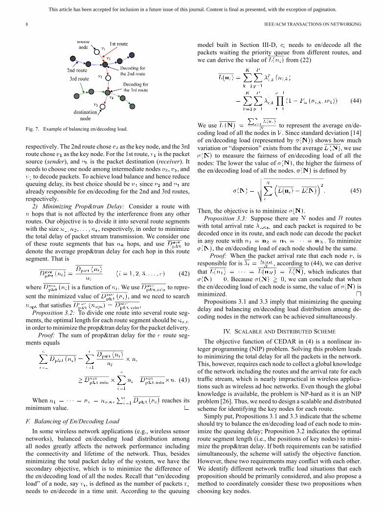
This article has been accepted for inclusion in a future issue of this journal. Content is final as presented, with the exception of pagination.
8 IEEE/ACM TRANSACTIONS ON NETWORKING
Fig. 7. Example of balancing en/decoding load.
respectively. The 2nd route chose as the key node, and the 3rdroute chose as the key node. For the 1st route, is the packetsource (sender), and is the packet destination (receiver). Itneeds to choose one node among intermediate nodes , , andto decode packets. To achieve load balance and hence reduce
queuing delay, its best choice should be since and arealready responsible for en/decoding for the 2nd and 3rd routes,respectively.2) Minimizing Prop&tran Delay: Consider a route withhops that is not affected by the interference from any other
routes. Our objective is to divide it into several route segmentswith the size , respectively, in order to minimizethe total delay of packet stream transmission. We consider oneof these route segments that has hops, and use todenote the average prop&tran delay for each hop in this routesegment. That is
(42)
where is a function of . We use to repre-
sent the minimized value of , and we need to search
that satisfies ,Proposition 3.2: To divide one route into several route seg-
ments, the optimal length for each route segment should bein order tominimize the prop&tran delay for the packet delivery.
Proof: The sum of prop&tran delay for the route seg-ments equals
(43)
When , reaches itsminimum value.
F. Balancing of En/Decoding Load
In some wireless network applications (e.g., wireless sensornetworks), balanced en/decoding load distribution amongall nodes greatly affects the network performance includingthe connectivity and lifetime of the network. Thus, besidesminimizing the total packet delay of the system, we have thesecondary objective, which is to minimize the difference ofthe en/decoding load of all the nodes. Recall that “en/decodingload” of a node, say , is defined as the number of packetsneeds to en/decode in a time unit. According to the queuing
model built in Section III-D, needs to en/decode all thepackets waiting the priority queue from different routes, andwe can derive the value of from (22)
(44)
We use to represent the average en/de-coding load of all the nodes in . Since standard deviation [14]of en/decoding load (represented by ) shows how muchvariation or “dispersion” exists from the average , we use
to measure the fairness of en/decoding load of all thenodes: The lower the value of , the higher the fairness ofthe en/decoding load of all the nodes. is defined by
(45)
Then, the objective is to minimize .Proposition 3.3: Suppose there are nodes and routes
with total arrival rate and each packet is required to bedecoded once in its route, and each node can decode the packetin any route with . To minimize
, the en/decoding load of each node should be the same.Proof: When the packet arrival rate that each node is
responsible for is , according to (44), we can derivethat , which indicates that
. Because , we can conclude that whenthe en/decoding load of each node is same, the value of isminimized.Propositions 3.1 and 3.3 imply that minimizing the queuing
delay and balancing en/decoding load distribution among de-coding nodes in the network can be achieved simultaneously.
IV. SCALABLE AND DISTRIBUTED SCHEME
The objective function of CEDAR in (4) is a nonlinear in-teger programming (NIP) problem. Solving this problem leadsto minimizing the total delay for all the packets in the network.This, however, requires each node to collect a global knowledgeof the network including the routes and the arrival rate for eachtraffic stream, which is nearly impractical in wireless applica-tions such as wireless ad hoc networks. Even though the globalknowledge is available, the problem is NP-hard as it is an NIPproblem [26]. Thus, we need to design a scalable and distributedscheme for identifying the key nodes for each route.Simply put, Propositions 3.1 and 3.3 indicate that the scheme
should try to balance the en/decoding load of each node to min-imize the queuing delay; Proposition 3.2 indicates the optimalroute segment length (i.e., the positions of key nodes) to mini-mize the prop&tran delay. If both requirements can be satisfiedsimultaneously, the scheme will satisfy the objective function.However, these two requirements may conflict with each other.We identify different network traffic load situations that eachproposition should be primarily considered, and also propose amethod to coordinately consider these two propositions whenchoosing key nodes.

This article has been accepted for inclusion in a future issue of this journal. Content is final as presented, with the exception of pagination.
QIU et al.: CEDAR: LOW-LATENCY AND DISTRIBUTED STRATEGY FOR PACKET RECOVERY IN WIRELESS NETWORKS 9
Algorithm 1: Identify key nodes in route executed by eachnode in in a light-traffic network.
beginSet SEN_FIN, REC_FIN and DEC to 0 ;while or doListen to other nodes;if it has received ACK_REC from the next node inthen
;if it receives (OPT_HOP, FLAG) from the previousnode in then
;Send ACK_REC to the previous node;if then
// It is a key node;;
else;
A. Case I (Light Traffic)
When a wireless network has light traffic, because the influ-ence from queuing delay is much less significant, and on av-erage en/decoding load of each node is low, we mainly con-sider the prop&tran delay. As Proposition 3.2 indicates, we firstsearch the value of and then set , andset . In a routing algorithm [27], everynode keeps a routing table, and a source node sends out a mes-sage to find the route to a destination for transmitting a packetstream. After a source–destination route has been discovered,each node in the route determines whether it is a key node ina distributed manner by executing the key node identificationalgorithm. Algorithm 1 presents the pseudocode of this algo-rithm executed by every node (except source node and destina-tion node), say , in a route in the case of light network traffic.Basically, the source node sends a packet (OPT_HOP, FLAG)through the route and nodes. FLAG is decreased by one in eachhop, and the node receiving the packet with is a keynode. This node then restores before for-warding the packet to the next node. Here, SEN_FIN presentswhether has received ACK from the next node in ; REC_FINpresents whether has received (OPT_HOP, FLAG) from theprevious node in ; DEC presents whether is responsible foren/decoding;
B. Case II (Heavy Traffic)
When a wireless network has heavy traffic, we aim to reducequeuing delay while reducing the prop&tran delay. Also, weneed to decrease the difference of en/decoding load overall thenetwork. Fortunately, according to Propositions 3.1 and 3.3, de-creasing queuing delay and increasing load balancing of the net-work can be achieved simultaneously.When a new route is built, the CEDAR scheme first executes
Algorithm 1. When executing the algorithm, each node alongthe route piggybacks its en/decoding load to the packet, and thelast node sends the collected en/decoding load information tothe source node. The source node then knows the series of nodesidentified as “potential key nodes” and their en/decoding loadand calculates the average en/decoding load through the route,
denoted as AVE_LOAD. It then checks whether the en/decodingload of each identified key node is larger than a predefinedthreshold (AVE_LOAD + BOUND), where BOUND is a pre-determined value. An overloaded potential key node is replacedby the node closest to itself in the route that has load below thethreshold. We use to denote the en/decoding load of thnode in the route. If ,then the source node compares and , andchooses the node with smaller en/decoding load if the en/de-coding load is smaller than the threshold. If both and
are larger than the threshold, the source node com-pares and . The source node repeats thisprocess until finding a node with load below the threshold orthe next two nodes needs to be compared are out of the range of
. The pseudocode ofthis algorithm is presented in Algorithm 2. In order to release thekey node selection load on the source node, this algorithm can beeasily extended to a fully decentralized algorithm. Specifically,the destination node calculates the AVE_LOAD and forwardsit back to the source node along the route. Each node checkswhether its own load is beyond the threshold. If so, it probes itsnearby nodes sequentially until finding a node with load withinthe threshold or meeting an identified potential key node.In dynamic wireless networks, the network topology and the
packet arrival rates change over time, which require nodes torecalculate the key nodes periodically. Based on Algorithms 1and 2, we see that such dynamics only affect the route length andthe en/decoding load of each node in the route that are neededin key node calculation. Thus, to deal with the dynamics, welet the sender periodically send a packet through the route toprobe this information. As a result, the key nodes calculated bya packet sender are the correct key nodes for the current networkenvironment, and CEDAR is adaptive to the network dynamics.
V. PERFORMANCE EVALUATION
This section presents the results of experiments onNESTbed [28] and simulation with MATLAB. We comparedCEDAR to the global optimal solution (OPTIMAL), the tradi-tional link-layer protocols, where a packet is decoded hop byhop [6], [16] (HBH), and to another solution where a packet isonly decoded at the destination (DEST). In order to evaluatethe effect of the load balancing algorithm (Algorithm 2) inCEDAR, we also test the performance of CEDAR without thisalgorithm denoted by CEDAR*. We measured the followingmetrics: 1) packet delay: the time interval from the time a packetis generated by the source node to the time that the packet issuccessfully decoded at the destination node; 2) throughput:the total number of data bits successfully decoded at the des-tinations per time unit (millisecond) in the entire network;3) en/decoding load: the number of packets a node en/decodes;4) number of probing messages: the total number of messagesused for probing.
A. Experiments on Real-World NESTbed
NESTbed is an open testbed for developing wireless sensorsystems [28]. It is a collection of 80 TELOSB sensors that are ar-ranged in a grid. The sensors have a CC2420 Chip and commu-nicate using the IEEE 802.15.4 standard. We verify our math-ematical models and evaluate the performance of CEDAR onNESTbed. We created a multihop network of TELOSB sensors

This article has been accepted for inclusion in a future issue of this journal. Content is final as presented, with the exception of pagination.
10 IEEE/ACM TRANSACTIONS ON NETWORKING
Fig. 8. Comparison of real-world NESTbed results. (a) BER in multiple hops.(b) Successful decoding rate.
Algorithm 2: Select key nodes with consideration of loadbalance in a heavy-traffic or normal-traffic network.
beginUse Algorithm 1 to get the “potential key nodes” inroute ;Let node be one node selected as the “potential keynode”;
;while doif thenif thenreturn ;
elseif thenreturn ;
;return 0;
running Tiny-OS 2.1.0 written in NESC.We use Reed–Solomoncodes to detect and fix errors in a packet; if the number of errorbits exceeds the capability of Reed–Solomon codes for correc-tion, the receiver asks for retransmission.Mathematical Model Verification: We measured BER after
the packet traveled for different numbers of hops in two sce-narios, common and noises. Fig. 8(a) shows BER versus thenumber of hops. We see that BER increases as the number ofhops increases in both scenarios. This is because as the numberof hops increases, more flipped bits are generated, and errorstend to be cumulative and propagated along a routing path in themultihop network. Also, common produces much lower BERthan noises as more noises increase BER.We then measured the probability of successful decoding
when the error correction node [responsible of error correctioncode (ECC)] is away from the source node by a differentnumber of hops and when the parity symbols have differentlengths. Fig. 8(b) shows the probability of successful decodingin a multihop network with varying parity symbol lengths andthe number of hops between the error correction node and thesource node. The figure illustrates that if the error correctionnode is farther away from the source, the probability of a packetdrop increases. Also, when the length of parity symbols in-creases, the probability of successful decoding increases, whichis consistent with (13). Furthermore, when the number of hopsis large, increasing the length of parity symbols will not guar-antee the successful decoding of a packet. The experimentalresults indicate that in order to maintain a high throughput and
Fig. 9. Experimental results on real-world NESTbed. (a) Packet delay.(b) Throughput.
low packet drop rate, it is necessary to fix errors in the packetas soon as possible. Thus, arranging the destination to decodethe packets is not an effective method. However, performingretransmission or ECC at every hop is not efficient due toqueuing delays. An effective method to decode a packet is tofix errors in the intermediate nodes, which can successfullydecode the packet while increasing the efficiency.Scheme Performance Evaluation: In the experiments on
NESTbed, we chose eight sources and eight destinations, andthe source–destination path length was 75 hops. Given that datarate kb/s, average [common scenarioin Fig. 8(a)], B, and B, we calculate theoptimal number of hops one packet should be decoded once is9 and 10.Each source node generated 500 packets at a time interval
varying from 80 to 160 ms. We measured the delay of transmis-sions and the throughput, which is defined as the total size ofall the packets divided by the total time used for transmitting allthe packets. The packet error rate is defined as the average per-cent of unsuccessfully transmitted packets in each hop. To testthe performance of the three schemes in different environments,we manually changed the packet error rate from 1/15 to 1/33.Fig. 9(a) shows the packet delay of CEDAR, DEST, and HBH.We find that the average packet delay of CEDAR is much lowerthan that of DEST and HBH. DEST has the highest delay be-cause it assigns the decoding work to each packet’s destinationrather than the intermediate nodes, which generatesmuch higherprobability of packet redecoding due to higher probability ofpacket errors, thus increasing the delay. The delay of HBH ishigher than that of CEDAR because HBH requires packets to been/decoded in each hop, which generates high en/decoding loadon intermediate nodes, leading to high queuing delay. Fig. 9(b)shows the throughput of three schemes. From the figure, we canfind that the throughput follows .This is because lower packet transmission delay usually leadsto higher throughput in the network.
B. Simulation on MATLAB
We conducted simulation onMATLAB to evaluate the perfor-mance of CEDAR.We built a 9 9 grid network with each nodelocated in one grid and randomly selected 16 pairs of sourcenode and destination node. Each packet contains 20 data sym-bols, five type-I parity symbols, and five type-II parity symbols.Each symbol has 5 bits. For the scheme using EEC code, thereare levels of EEC bits in each packet, with 5 EECbits in each level. Also, we randomly chose nodes connectingeach pair of source node and destination node as the route. We
This article has been accepted for inclusion in a future issue of this journal. Content is final as presented, with the exception of pagination.
QIU et al.: CEDAR: LOW-LATENCY AND DISTRIBUTED STRATEGY FOR PACKET RECOVERY IN WIRELESS NETWORKS 11
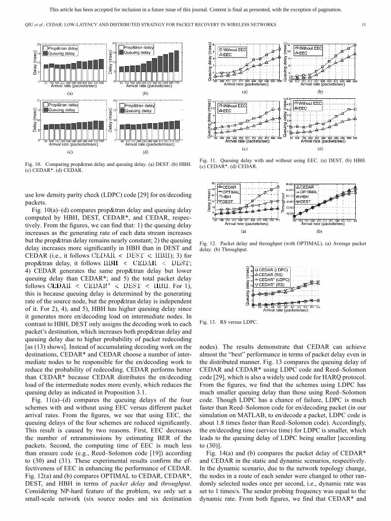
Fig. 10. Comparing prop&tran delay and queuing delay. (a) DEST. (b) HBH.(c) CEDAR*. (d) CEDAR.
use low density parity check (LDPC) code [29] for en/decodingpackets.Fig. 10(a)–(d) compares prop&tran delay and queuing delay
computed by HBH, DEST, CEDAR*, and CEDAR, respec-tively. From the figures, we can find that: 1) the queuing delayincreases as the generating rate of each data stream increasesbut the prop&tran delay remains nearly constant; 2) the queuingdelay increases more significantly in HBH than in DEST andCEDAR (i.e., it follows ); 3) forprop&tran delay, it follows ;4) CEDAR generates the same prop&tran delay but lowerqueuing delay than CEDAR*; and 5) the total packet delayfollows . For 1),this is because queuing delay is determined by the generatingrate of the source node, but the prop&tran delay is independentof it. For 2), 4), and 5), HBH has higher queuing delay sinceit generates more en/decoding load on intermediate nodes. Incontrast to HBH, DEST only assigns the decoding work to eachpacket’s destination, which increases both prop&tran delay andqueuing delay due to higher probability of packet redecoding[as (13) shows]. Instead of accumulating decoding work on thedestinations, CEDAR* and CEDAR choose a number of inter-mediate nodes to be responsible for the en/decoding work toreduce the probability of redecoding. CEDAR performs betterthan CEDAR* because CEDAR distributes the en/decodingload of the intermediate nodes more evenly, which reduces thequeuing delay as indicated in Proposition 3.1.Fig. 11(a)–(d) compares the queuing delays of the four
schemes with and without using EEC versus different packetarrival rates. From the figures, we see that using EEC, thequeuing delays of the four schemes are reduced significantly.This result is caused by two reasons. First, EEC decreasesthe number of retransmissions by estimating BER of thepackets. Second, the computing time of EEC is much lessthan erasure code (e.g., Reed–Solomon code [19]) accordingto (30) and (31). These experimental results confirm the ef-fectiveness of EEC in enhancing the performance of CEDAR.Fig. 12(a) and (b) compares OPTIMAL to CEDAR, CEDAR*,DEST, and HBH in terms of packet delay and throughput.Considering NP-hard feature of the problem, we only set asmall-scale network (six source nodes and six destination
Fig. 11. Queuing delay with and without using EEC. (a) DEST. (b) HBH.(c) CEDAR*. (d) CEDAR.
Fig. 12. Packet delay and throughput (with OPTIMAL). (a) Average packetdelay. (b) Throughput.
Fig. 13. RS versus LDPC.
nodes). The results demonstrate that CEDAR can achievealmost the “best” performance in terms of packet delay even inthe distributed manner. Fig. 13 compares the queuing delay ofCEDAR and CEDAR* using LDPC code and Reed–Solomoncode [29], which is also a widely used code for HARQ protocol.From the figures, we find that the schemes using LDPC hasmuch smaller queuing delay than those using Reed–Solomoncode. Though LDPC has a chance of failure, LDPC is muchfaster than Reed–Solomon code for en/decoding packet (in oursimulation on MATLAB, to en/decode a packet, LDPC code isabout 1.8 times faster than Reed–Solomon code). Accordingly,the en/decoding time (service time) for LDPC is smaller, whichleads to the queuing delay of LDPC being smaller [accordingto (30)].Fig. 14(a) and (b) compares the packet delay of CEDAR*
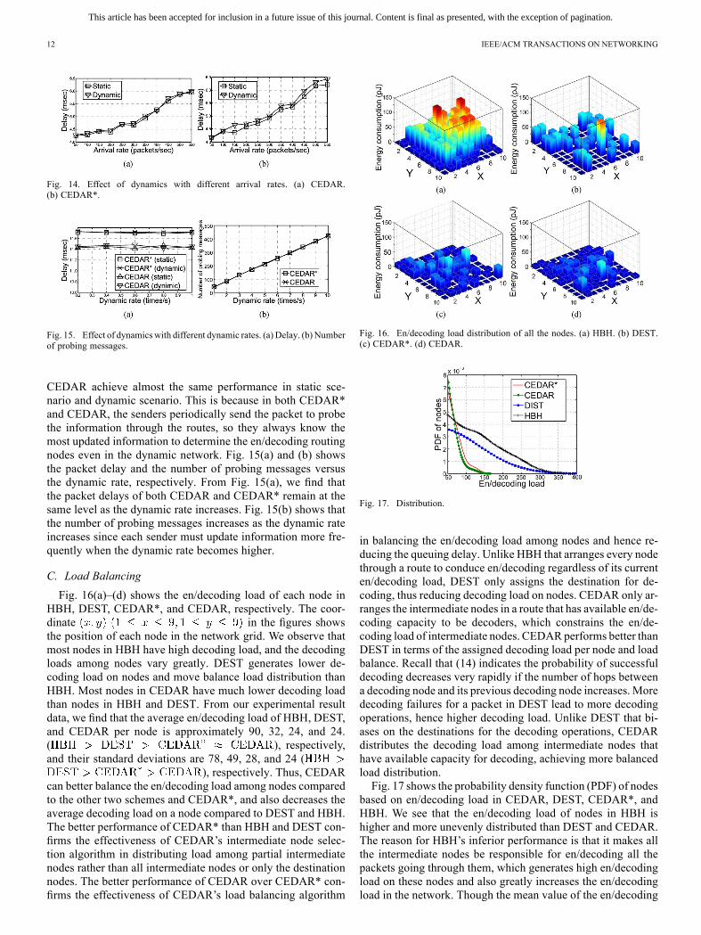
and CEDAR in the static and dynamic scenarios, respectively.In the dynamic scenario, due to the network topology change,the nodes in a route of each sender were changed to other ran-domly selected nodes once per second, i.e., dynamic rate wasset to 1 times/s. The sender probing frequency was equal to thedynamic rate. From both figures, we find that CEDAR* and
This article has been accepted for inclusion in a future issue of this journal. Content is final as presented, with the exception of pagination.
12 IEEE/ACM TRANSACTIONS ON NETWORKING
Fig. 14. Effect of dynamics with different arrival rates. (a) CEDAR.(b) CEDAR*.
Fig. 15. Effect of dynamics with different dynamic rates. (a) Delay. (b) Numberof probing messages.
CEDAR achieve almost the same performance in static sce-nario and dynamic scenario. This is because in both CEDAR*and CEDAR, the senders periodically send the packet to probethe information through the routes, so they always know themost updated information to determine the en/decoding routingnodes even in the dynamic network. Fig. 15(a) and (b) showsthe packet delay and the number of probing messages versusthe dynamic rate, respectively. From Fig. 15(a), we find thatthe packet delays of both CEDAR and CEDAR* remain at thesame level as the dynamic rate increases. Fig. 15(b) shows thatthe number of probing messages increases as the dynamic rateincreases since each sender must update information more fre-quently when the dynamic rate becomes higher.
C. Load Balancing
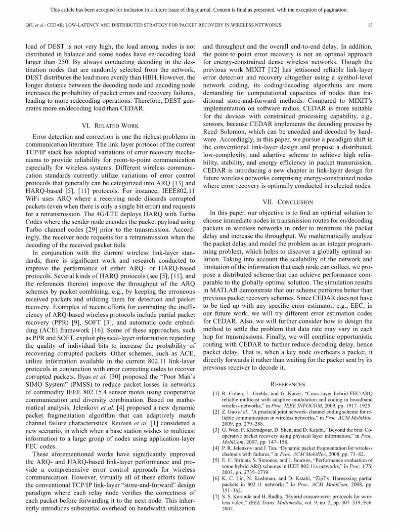
Fig. 16(a)–(d) shows the en/decoding load of each node inHBH, DEST, CEDAR*, and CEDAR, respectively. The coor-dinate in the figures showsthe position of each node in the network grid. We observe thatmost nodes in HBH have high decoding load, and the decodingloads among nodes vary greatly. DEST generates lower de-coding load on nodes and move balance load distribution thanHBH. Most nodes in CEDAR have much lower decoding loadthan nodes in HBH and DEST. From our experimental resultdata, we find that the average en/decoding load of HBH, DEST,and CEDAR per node is approximately 90, 32, 24, and 24.( ), respectively,and their standard deviations are 78, 49, 28, and 24 (
), respectively. Thus, CEDARcan better balance the en/decoding load among nodes comparedto the other two schemes and CEDAR*, and also decreases theaverage decoding load on a node compared to DEST and HBH.The better performance of CEDAR* than HBH and DEST con-firms the effectiveness of CEDAR’s intermediate node selec-tion algorithm in distributing load among partial intermediatenodes rather than all intermediate nodes or only the destinationnodes. The better performance of CEDAR over CEDAR* con-firms the effectiveness of CEDAR’s load balancing algorithm
Fig. 16. En/decoding load distribution of all the nodes. (a) HBH. (b) DEST.(c) CEDAR*. (d) CEDAR.
Fig. 17. Distribution.
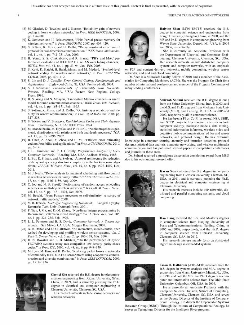
in balancing the en/decoding load among nodes and hence re-ducing the queuing delay. Unlike HBH that arranges every nodethrough a route to conduce en/decoding regardless of its currenten/decoding load, DEST only assigns the destination for de-coding, thus reducing decoding load on nodes. CEDAR only ar-ranges the intermediate nodes in a route that has available en/de-coding capacity to be decoders, which constrains the en/de-coding load of intermediate nodes. CEDARperforms better thanDEST in terms of the assigned decoding load per node and loadbalance. Recall that (14) indicates the probability of successfuldecoding decreases very rapidly if the number of hops betweena decoding node and its previous decoding node increases. Moredecoding failures for a packet in DEST lead to more decodingoperations, hence higher decoding load. Unlike DEST that bi-ases on the destinations for the decoding operations, CEDARdistributes the decoding load among intermediate nodes thathave available capacity for decoding, achieving more balancedload distribution.Fig. 17 shows the probability density function (PDF) of nodes
based on en/decoding load in CEDAR, DEST, CEDAR*, andHBH. We see that the en/decoding load of nodes in HBH ishigher and more unevenly distributed than DEST and CEDAR.The reason for HBH’s inferior performance is that it makes allthe intermediate nodes be responsible for en/decoding all thepackets going through them, which generates high en/decodingload on these nodes and also greatly increases the en/decodingload in the network. Though the mean value of the en/decoding
This article has been accepted for inclusion in a future issue of this journal. Content is final as presented, with the exception of pagination.
QIU et al.: CEDAR: LOW-LATENCY AND DISTRIBUTED STRATEGY FOR PACKET RECOVERY IN WIRELESS NETWORKS 13
load of DEST is not very high, the load among nodes is notdistributed in balance and some nodes have en/decoding loadlarger than 250. By always conducting decoding in the des-tination nodes that are randomly selected from the network,DEST distributes the load more evenly than HBH. However, thelonger distance between the decoding node and encoding nodeincreases the probability of packet errors and recovery failures,leading to more redecoding operations. Therefore, DEST gen-erates more en/decoding load than CEDAR.
VI. RELATED WORK
Error detection and correction is one the richest problems incommunication literature. The link-layer protocol of the currentTCP/IP stack has adopted variations of error recovery mecha-nisms to provide reliability for point-to-point communicationespecially for wireless systems. Different wireless communi-cation standards currently utilize variations of error controlprotocols that generally can be categorized into ARQ [13] andHARQ-based [5], [11] protocols. For instance, IEEE802.11WiFi uses ARQ where a receiving node discards corruptedpackets (even when there is only a single bit error) and requestsfor a retransmission. The 4G/LTE deploys HARQ with TurboCodes where the sender node encodes the packet payload usingTurbo channel codes [29] prior to the transmission. Accord-ingly, the receiver node requests for a retransmission when thedecoding of the received packet fails.In conjunction with the current wireless link-layer stan-
dards, there is significant work and research conducted toimprove the performance of either ARQ- or HARQ-basedprotocols. Several kinds of HARQ protocols (see [5], [11], andthe references therein) improve the throughput of the ARQschemes by packet combining, e.g., by keeping the erroneousreceived packets and utilizing them for detection and packetrecovery. Examples of recent efforts for combating the ineffi-ciency of ARQ-based wireless protocols include partial packetrecovery (PPR) [9], SOFT [3], and automatic code embed-ding (ACE) framework [16]. Some of these approaches, suchas PPR and SOFT, exploit physical-layer information regardingthe quality of individual bits to increase the probability ofrecovering corrupted packets. Other schemes, such as ACE,utilize information available in the current 802.11 link-layerprotocols in conjunction with error correcting codes to recovercorrupted packets. Ilyas et al. [30] proposed the “Poor Man’sSIMO System” (PMSS) to reduce packet losses in networksof commodity IEEE 802.15.4 sensor motes using cooperativecommunication and diversity combination. Based on mathe-matical analysis, Jelenkovi et al. [4] proposed a new dynamicpacket fragmentation algorithm that can adaptively matchchannel failure characteristics. Reuven et al. [1] considered anew scenario, in which when a base station wishes to multicastinformation to a large group of nodes using application-layerFEC codes.These aforementioned works have significantly improved
the ARQ- and HARQ-based link-layer performance and pro-vide a comprehensive error control approach for wirelesscommunication. However, virtually all of these efforts followthe conventional TCP/IP link-layer “store-and-forward” designparadigm where each relay node verifies the correctness ofeach packet before forwarding it to the next node. This inher-ently introduces substantial overhead on bandwidth utilization
and throughput and the overall end-to-end delay. In addition,the point-to-point error recovery is not an optimal approachfor energy-constrained dense wireless networks. Though theprevious work MIXIT [12] has jettisoned reliable link-layererror detection and recovery altogether using a symbol-levelnetwork coding, its coding/decoding algorithms are moredemanding for computational capacities of nodes than tra-ditional store-and-forward methods. Compared to MIXIT’simplementation on software radios, CEDAR is more suitablefor the devices with constrained processing capability, e.g.,sensors, because CEDAR implements the decoding process byReed–Solomon, which can be encoded and decoded by hard-ware. Accordingly, in this paper, we pursue a paradigm shift inthe conventional link-layer design and propose a distributed,low-complexity, and adaptive scheme to achieve high relia-bility, stability, and energy efficiency in packet transmission.CEDAR is introducing a new chapter in link-layer design forfuture wireless networks comprising energy-constrained nodeswhere error recovery is optimally conducted in selected nodes.
VII. CONCLUSION
In this paper, our objective is to find an optimal solution tochoose immediate nodes in transmission routes for en/decodingpackets in wireless networks in order to minimize the packetdelay and increase the throughput. We mathematically analyzethe packet delay and model the problem as an integer program-ming problem, which helps to discover a globally optimal so-lution. Taking into account the scalability of the network andlimitation of the information that each node can collect, we pro-pose a distributed scheme that can achieve performance com-parable to the globally optimal solution. The simulation resultsin MATLAB demonstrate that our scheme performs better thanprevious packet recovery schemes. Since CEDAR does not haveto be tied up with any specific error estimator, e.g., EEC, inour future work, we will try different error estimation codesfor CEDAR. Also, we will further consider how to design themethod to settle the problem that data rate may vary in eachhop for transmissions. Finally, we will combine opportunisticrouting with CEDAR to further reduce decoding delay, hencepacket delay. That is, when a key node overhears a packet, itdirectly forwards it rather than waiting for the packet sent by itsprevious receiver to decode it.
REFERENCES[1] R. Cohen, L. Grebla, and G. Katzir, “Cross-layer hybrid FEC/ARQ
reliable multicast with adaptive modulation and coding in broadbandwireless networks,” in Proc. IEEE INFOCOM, 2009, pp. 1917–1925.
[2] Z. Guo et al., “A practical joint network- channel coding scheme for re-liable communication in wireless networks,” in Proc. ACM MobiHoc,2009, pp. 279–288.
[3] G. Woo, P. Kheradpour, D. Shen, and D. Katabi, “Beyond the bits: Co-operative packet recovery using physical layer information,” in Proc.MobiCom, 2007, pp. 147–158.
[4] P. R. Jelenkovi and J. Tan, “Dynamic packet fragmentation for wirelesschannels with failures,” in Proc. ACM MobiHoc, 2008, pp. 73–82.
[5] E. C. Strinati, S. Simoens, and J. Boutros, “Performance evaluation ofsome hybrid ARQ schemes in IEEE 802.11a networks,” in Proc. VTS,2003, pp. 2735–2739.
[6] K. C. Lin, N. Kushman, and D. Katabi, “ZipTx: Harnessing partialpackets in 802.11 networks,” in Proc. ACM MobiCom, 2008, pp.351–362.
[7] S. S. Karande and H. Radha, “Hybrid erasure-error protocols for wire-less video,” IEEE Trans. Multimedia, vol. 9, no. 2, pp. 307–319, Feb.2007.
This article has been accepted for inclusion in a future issue of this journal. Content is final as presented, with the exception of pagination.
14 IEEE/ACM TRANSACTIONS ON NETWORKING
[8] M. Ghaderi, D. Towsley, and J. Kurose, “Reliability gain of networkcoding in lossy wireless networks,” in Proc. IEEE INFOCOM, 2008,pp. 196–200.
[9] K. Jamieson and H. Balakrishnan, “PPR: Partial packet recovery forwireless networks,” in Proc. SIGCOMM, 2007, pp. 409–420.
[10] S. Soltani, K. Misra, and H. Radha, “Delay constraint error controlprotocol for real-time video communication,” IEEE Trans.Multimedia,vol. 11, no. 4, pp. 742–751, Jun. 2009.
[11] H. Yomo, S. S. Chakraborty, and R. Prasad, “PHY and MAC per-formance evaluation of IEEE 802.11a WLAN over fading channels,”IETE J. Res., vol. 51, no. 1, pp. 83–94, Jan.–Feb. 2005.
[12] S. Katti, D. Katabi, H. Balakrishnan, and M. Medard, “Symbol-levelnetwork coding for wireless mesh networks,” in Proc. ACM SIG-COMM, 2008, pp. 401–412.
[13] S. Lin and D. J. Costello, Error Control Coding: Fundamentals andApplications. Englewood Cliffs, NJ, USA: Prentice-Hall, 2004.
[14] S. Chahramant, Fundamentals of Probability with StochasticProcess. Reading, MA, USA: Eastern New England CollegePress, 1986.
[15] H. S. Wang and N. Moayeri, “Finite-state Markov channel—A usefulmodel for radio communication channels,” IEEE Trans. Veh. Technol.,vol. 44, no. 1, pp. 163–171, Feb. 1995.
[16] S. Soltani, K. Misra, and H. Radha, “On link-layer reliability and sta-bility for wireless communication,” in Proc. ACMMobiCom, 2008, pp.327–338.
[17] S. Wicker and V. Bhargava, Reed-Solomon Codes and Their Applica-tions. Piscataway, NJ, USA: IEEE Press, 1994.
[18] M. Mandelbaum, M. Hlynka, and P. H. Brill, “Nonhomogeneous geo-metric distributions with relations to birth and death processes,” TOP,vol. 15, pp. 281–296, 2007.
[19] B. Chen, Z. Zhou, Y. Zhao, and H. Yu, “Efficient error estimatingcoding: Feasibility and applications,” in Proc. ACM SIGCOMM, 2010,pp. 3–14.
[20] J. L. Hammond and P. J. O’Reilly, Performance Analysis of LocalComputer Networks. Reading, MA, USA: Addison-Wesley, 1988.
[21] L. Bui, R. Srikant, and A. Stolyar, “A novel architecture for reductionof delay and queueing structure complexity in the back-pressure algo-rithm,” IEEE/ACM Trans. Netw., vol. 19, no. 6, pp. 1597–1609, Dec.2011.
[22] M. J. Neely, “Delay analysis for maximal scheduling with flow controlin wireless networks with bursty traffic,” IEEE/ACM Trans. Netw., vol.17, no. 4, pp. 1146–1159, Aug. 2009.
[23] C. Joo and N. B. Shroff, “Performance of random access schedulingschemes in multi-hop wireless networks,” IEEE/ACM Trans. Netw.,vol. 17, no. 5, pp. 1481–1493, Oct. 2009.
[24] M. Becchi, “From Poisson processes to self-similarity: A survey ofnetwork traffic models,” 2008.
[25] V. B. Iversen, Teletraffic Engineering Handbook. Kongens Lyngby,Denmark: Tech. Univ. Denmark Press, 2001.
[26] P. Tian, J. Ma, and D.-M. Zhang, “Non-linear integer programming byDarwin and Boltzmann mixed strategy,” Eur. J. Oper. Res., vol. 105,no. 1, pp. 224–235, Feb. 1996.
[27] L. L. Peterson and B. S. Davie, Computer Network: A System Ap-proach. San Mateo, CA, USA: Morgan Kaufmann, 2007.
[28] A. R. Dalton and J. O. Hallstrom, “An interactive, source-centric, opentestbed for developing and profiling wireless sensor systems,” Int. J.Distrib. Sensor Netw., vol. 5, no. 2, pp. 105–138, Mar. 2009.
[29] D. N. Rowitch and L. B. Milstein, “On the performance of hybridFEC/ARQ systems using rate-compatible low-density parity-checkcodes,” in Proc. ITC, 2000, vol. 48, no. 6, pp. 948–959.
[30] M. Ilyas, M. Kim, and H. Radha, “Reducing packet losses in networksof commodity IEEE 802.15.4 sensor motes using cooperative commu-nication and diversity combination,” in Proc. IEEE INFOCOM, 2009,pp. 1818–1826.
Chenxi Qiu received the B.S. degree in telecommu-nication engineering from Xidian University, Xi’an,China, in 2009, and is currently pursuing the Ph.D.degree in electrical and computer engineering atClemson University, Clemson, SC, USA.His research interests include sensor networks and
wireless networks.
Haiying Shen (M’06–SM’13) received the B.S.degree in computer science and engineering fromTongji University, Shanghai, China, in 2000, and theMS and Ph.D. degrees in computer engineering fromWayne State University, Detroit, MI, USA, in 2004and 2006, respectively.She is currently an Associate Professor with
the Department of Electrical and Computer Engi-neering, Clemson University, Clemson, SC, USA.Her research interests include distributed computersystems and computer networks, with an emphasis
on P2P and content delivery networks, mobile computing, wireless sensornetworks, and grid and cloud computing.Dr. Shen is a Microsoft Faculty Fellow of 2010 and a member of the Asso-
ciation for Computing Machinery (ACM). She was the Program Co-Chair for anumber of international conferences and member of the Program Committee ofmany leading conferences.
Sohraab Soltani received the B.E. degree (Hons.)from the Shiraz University, Shiraz, Iran, in 2003, andtheM.S. and Ph.D. degrees fromMichigan State Uni-versity (MSU), East Lansing, MI, USA, in 2006 and2009, respectively, all in computer science.He has been a PI or Co-PI in several NSF, SBIR,
and STTR projects. His research interests includecomputer security, stochastic models, data mining,statistical information inference, wireless video andcognitive mobile communications, ad hoc and sensornetworks, and protocol design. He has extensive
knowledge in computer security, anomaly and intrusion detection, protocoldesign, statistical data analysis, computer networking, and wireless multimediacommunication and has published several papers in competitive conferencesand journals in these areas.Dr. Soltani received a prestigious dissertation completion award from MSU
due to his outstanding research effort.
Karan Sapra received the B.S. degree in computerengineering from Clemson University, Clemson, SC,USA, in 2011, and is currently pursuing the Ph.D.degree in electrical and computer engineering atClemson University.His research interests include P2P networks, dis-
tributed and parallel computing systems, and cloudcomputing.
Hao Jiang received the B.S. and Master’s degreesin computer science from Nanjing University ofPosts and Telecommunications, Nanjing, China, in2006 and 2008, respectively, and the Ph.D. degreein computer science from Clemson University,Clemson, SC, USA, in 2012.His research interests mainly focus on distributed
algorithm design in embedded systems.
Jason O. Hallstrom (A’08–M’08) received both theB.S. degree in systems analysis and M.A. degree ineconomics fromMiami University, Miami, FL, USA,in 1998, and both the M.S. and Ph.D. degrees in com-puter and information science from The Ohio StateUniversity, Columbus, OH, USA, in 2004.He is currently an Associate Professor with the
Computer Science Division, School of Computing,Clemson University, Clemson, SC, USA, and servesas the Deputy Director of the Institute of Computa-tional Ecology. He directs the Dependable Systems
Research Group (DSRG). Through the Institute of Computational Ecology, heserves as Technology Director for the Intelligent River program.
![Fine-grained Encountering Information Collection under ...cs.virginia.edu/~hs6ms/publishedPaper/Conference... · As a special form of delay tolerant networks (DTNs) [1], mobile opportunistic](https://img.pdfslide.us/doc/110x75/5f8c0f688bd35e3c866e456a/fine-grained-encountering-information-collection-under-cs-hs6mspublishedpaperconference.jpg)


![SocialLink: Utilizing Social Network and Transaction Links ...hs6ms/publishedPaper/... · • Social network based P2P file sharing [PerCom’08, CoRR’11, ICNP’12,IPDPS’09]](https://img.pdfslide.us/doc/110x75/60065f397e31ab08c86bf546/sociallink-utilizing-social-network-and-transaction-links-hs6mspublishedpaper.jpg)


![DIAL: A Distributed Adaptive-Learning Routing Method in VDTNscs.virginia.edu/~hs6ms/publishedPaper/Conference/2016/... · 2016-04-21 · [1] T. Henderson, etc. “The changing usage](https://img.pdfslide.us/doc/110x75/5f7bfe18ed3c330fdd019a1f/dial-a-distributed-adaptive-learning-routing-method-in-hs6mspublishedpaperconference2016.jpg)


![Comparing Application Performance on HPC-based Hadoop ...hs6ms/publishedPaper/Conference/201… · with different job characteristics (data-intensive, CPU-intensive, I/O-intensive)[1]](https://img.pdfslide.us/doc/110x75/6019fcbd6636232716413fe9/comparing-application-performance-on-hpc-based-hadoop-hs6mspublishedpaperconference201.jpg)