Embed Size (px)
Citation preview
03102r0P802-15_TG3a-FemtoDevices-CFP-Document.doc Jonathon Cheah May 9 2003
IEEE P802.15Wireless Personal Area Networks
Project IEEE P802.15 Working Group for Wireless Personal Area Networks (WPANs)
Title Supporting Materials for Femto Devices May Presentation document: 03101r1P802-15_TG3a-femtoDevices-CFP-Document.doc
Date Submitted
9 May, 2003
Source [Jonathon Cheah][femto Devices][5897 Oberlin Drive, Suite 208San Diego, CA 92121. ]
Voice: [858-404-0457]Fax: [858-404-0457]E-mail: [[email protected]]
Re: IEEE P802.15 Alternative PHY Call For Proposals
03102r0P802-15_TG3a-FemtoDevices-CFP-Document.doc
Abstract Base-band processing of whitening data to reduce power spectral density of UWB signals in IEEE 802.15.3 systems.
Purpose Proposal of base-band processing of whitening data to reduce power spectral density of UWB signals in IEEE 802.15.3 systems.
Notice This document has been prepared to assist the IEEE P802.15. It is offered as a basis for discussion and is not binding on the contributing individual(s) or organization(s). The material in this document is subject to change in form and content after further study. The contributor(s) reserve(s) the right to add, amend or withdraw material contained herein.
Release The contributor acknowledges and accepts that this contribution becomes the property of IEEE and may be made publicly available by P802.15.
1

03102r0P802-15_TG3a-FemtoDevices-CFP-Document.doc Jonathon Cheah May 9 2003
1. Introduction
Benefiting from the experience in the wireless data systems component market, from CDPD, WLAN to the nascent Bluetooth technology, it is clear that the key element for a successful deployment of the technology is basically the cost of the technology.
The cost element is even more important when the technology is intended for the short range wire replacement market. In this case, the cost of technology cannot be any more than the price the consumer is willing to pay to get the perceived “convenience of use”. This is because, in the short range wire replacement situation, there is no “mission critical, must have” compelling reason, where the inconvenience of a short wire can be tolerated.
Thus the main goal of the PHY design should be the feasibility of cost of the technology to provide intended functional performance. In other others, the goal of the optimum design is one that provides minimum design configuration, with the simplest possible solution without the burden of “Nice to have features”.
2. PHY Specification Summary
3 x Maury-Styles length 30 unique word Wake-UP code, using OOK modulation. BPSK modulation. Length 11 Time-Frequency Code with 8 frequency channels. Allows 10 Piconet codes. Allows Scatter-net operation Gaussian wave-shaped pulses Preamble consists of 10 x length 31 rake training sequence followed by 500 bit
equalizer training m-sequence 2 finger Rake receiver followed by 16 tap feed forward and 16 tap feedback
equalizer. Convolution rate ½ constraint length 7 FEC. Gaussian filter shape Channel plan.
Basic Channel Plans:
Channel No. Channel fc -4.3 dB (signal) -10 dB (FCC)1 4.000 Ghz 3.6Ghz 4.4Ghz 3.4Ghz 4.6Ghz2 4.800 Ghz 4.4Ghz 5.2Ghz 4.2Ghz 5.4Ghz3 5.600 Ghz 5.2Ghz 6.0Ghz 5.0Ghz 6.2ghz4 6.400 Ghz 6.0 Ghz 6.8 Ghz 5.8Ghz 7.0Ghz5 7.200 Ghz 6.8 Ghz 7.6Ghz 6.6Ghz 7.8Ghz6 8.000 Ghz 7.6Ghz 8.4Ghz 7.4ghz 8.6Ghz7 8.800 Ghz 8.4Ghz 9.2Ghz 8.2Ghz 9.4Ghz8 9.600 Ghz 9.2Ghz 10.0Ghz 9.0Ghz 10.2Ghz
Table 1. Basic Channel Plan
2

03102r0P802-15_TG3a-FemtoDevices-CFP-Document.doc Jonathon Cheah May 9 2003
3. NII Band Coexistence
Although NII bands cover the frequency ranges : 5.15-5.25 Ghz, 5.25-5.35 Ghz and 5.75-5.85 Ghz, to date, the IEEE802.11a products use only 5.15-5.25 band.
From the channel plan assignment, the interference potentials between IEEE802.11a and IEEE802.15.3a can be avoided by omitting channel 2 or channel 3 in the transmission where such an interference situation exists.
It is essential that the PHY structure allows the seamless integration of the avoidance of interference to and by IEEE802.11a devices. This feature should be included in the Time-Frequency code set.
4. Time Frequency Code Set
Time-frequency code set can be viewed as an orthonormal set ( )f t over the interval {0, T }such as:
after normalization,
By this definition, one can begin to construct an orthonormal time-frequency code set as closely representing this behavior. The selection of optimum orthonormal code set would clearly show that certain code length has optimum code yield such as length 7 code and length 11 code. Another interesting behavior from the ortho-normality is the possibility of the silence element #.
Silence element # is defined as no signal transmission. Silence element has the interesting property that if it coexists within the same time slot as another code, then it is not a collision. Silence element also allows the receiver the opportunity to check for other Piconet or interference during transmission, and therefore permits the creation of Scatter-net. Of course, the Silence element reduces Over-the-Air bit rate, and it also reduces the average transmit power.
3
03102r0P802-15_TG3a-FemtoDevices-CFP-Document.doc Jonathon Cheah May 9 2003
An unique code set for length 11 can be constructed with 8 basic channels and 3 silence elements. In the silence period, no pulse is transmitted. In this way, there is a means to assess the existence of concurrent piconet, or interference. Furthermore, the silence element provides increased code yield in the time-frequency code set.
The introduction of a silence element reduces the data speed by one time slot, however it also increases the available average power level specified by FCC by the same amount. The FCC rule of average power per Mhz allows Silence bit to be applied in trading power for speed. Therefore, there is an equitable compensating factor in the silence element.
Here, the proposal is a length 11 code with 10 piconet codes and a maximum of 10 collisions for 10 codes. It uses 8 channels and 3 Silence elements.
# denotes Silence element.
# 1 2 3 4 5 6 7 8 # ## 2 4 6 8 # 1 3 5 7 ## 3 6 # 1 4 7 # 2 5 8# 4 8 1 5 # 2 6 # 3 7# 5 # 4 # 3 8 2 7 1 6# 6 1 7 2 8 3 # 4 # 5# 7 3 # 6 2 # 5 1 8 4# 8 5 2 # 7 4 1 # 6 3# # 7 5 3 1 # 8 6 4 2# # # 8 7 6 5 4 3 2 1
Figure shows the Time-Frequency code table.
It is an interesting exercise to check the validity of the code set. Essentially, one can align all the same channel of each code in the same time slot. This defines the maximum collision potential, and check for any further alignment of channels in all of the used time slots.
It is easy to show that Length 7 code is optimum with 6 good codes, Length 8, 9, and 10 have very poor code yields of much less than N-1 . Length 11 code has 10 good codes.
5. Piconet Requirements
The ability to provide Piconet network connection is provided by the orthogonality of the Time-Frequency code set. The number of minimum interfering code population dictates the number of Piconets that can be supported.
4

03102r0P802-15_TG3a-FemtoDevices-CFP-Document.doc Jonathon Cheah May 9 2003
The ability for Scatternet operation is also very useful. Scatternet allows the device ability to straddle 2 or more Piconets at the same time.
Thus there is a need to provide as many non-interfering codes as possible, and from the preceding section, it can be observed that the most optimum code yield is length of the code set N -1,
For length 11 code shown in the preceding section, it is shown below that there are only a maximum of 10 collisions per time slot possible.
# 1 2 3 4 5 6 7 8 # # # 1 2 3 4 5 6 7 8 # ## 1 3 5 7 # # 2 4 6 8 # # 2 4 6 8 # 1 3 5 7# 1 4 7 # 2 5 8 # 3 6 7 # 2 5 8 # 3 6 # 1 48 1 5 # 2 6 # 3 7 # 4 5 # 2 6 # 3 7 # 4 8 17 1 6 # 5 # 4 # 3 8 2 3 8 2 7 1 6 # 5 # 4 #6 1 7 2 8 3 # 4 # 5 # 1 7 2 8 3 # 4 # 5 # 65 1 8 4 # 7 3 # 6 2 # # 6 2 # 5 1 8 4 # 7 34 1 # 6 3 # 8 5 2 # 7 8 5 2 # 7 4 1 # 6 3 #3 1 # 8 6 4 2 # # 7 5 6 4 2 # # 7 5 3 1 # 82 1 # # # 8 7 6 5 4 3 4 3 2 1 # # # 8 7 6 5
# 1 2 3 4 5 6 7 8 # # # 1 2 3 4 5 6 7 8 # #8 # 1 3 5 7 # # 2 4 6 7 # # 2 4 6 8 # 1 3 55 8 # 3 6 # 1 4 7 # 2 3 6 # 1 4 7 # 2 5 8 #2 6 # 3 7 # 4 8 1 5 # # 3 7 # 4 8 1 5 # 2 6# 4 # 3 8 2 7 1 6 # 5 6 # 5 # 4 # 3 8 2 7 17 2 8 3 # 4 # 5 # 6 1 2 8 3 # 4 # 5 # 6 1 74 # 7 3 # 6 2 # 5 1 8 # 5 1 8 4 # 7 3 # 6 21 # 6 3 # 8 5 2 # 7 4 5 2 # 7 4 1 # 6 3 # 8# 7 5 3 1 # 8 6 4 2 # 1 # 8 6 4 2 # # 7 5 36 5 4 3 2 1 # # # 8 7 8 7 6 5 4 3 2 1 # # #
# 1 2 3 4 5 6 7 8 # # # 1 2 3 4 5 6 7 8 # #6 8 # 1 3 5 7 # # 2 4 5 7 # # 2 4 6 8 # 1 31 4 7 # 2 5 8 # 3 6 # # 2 5 8 # 3 6 # 1 4 77 # 4 8 1 5 # 2 6 # 3 4 8 1 5 # 2 6 # 3 7 #2 7 1 6 # 5 # 4 # 3 8 # 3 8 2 7 1 6 # 5 # 48 3 # 4 # 5 # 6 1 7 2 3 # 4 # 5 # 6 1 7 2 83 # 6 2 # 5 1 8 4 # 7 8 4 # 7 3 # 6 2 # 5 1# 6 3 # 8 5 2 # 7 4 1 2 # 7 4 1 # 6 3 # 8 54 2 # # 7 5 3 1 # 8 6 7 5 3 1 # 8 6 4 2 # ## # 8 7 6 5 4 3 2 1 # 1 # # # 8 7 6 5 4 3 2
# 1 2 3 4 5 6 7 8 # # # 1 2 3 4 5 6 7 8 # #4 6 8 # 1 3 5 7 # # 2 3 5 7 # # 2 4 6 8 # 18 # 3 6 # 1 4 7 # 2 5 6 # 1 4 7 # 2 5 8 # 31 5 # 2 6 # 3 7 # 4 8 # 2 6 # 3 7 # 4 8 1 55 # 4 # 3 8 2 7 1 6 # 1 6 # 5 # 4 # 3 8 2 7# 4 # 5 # 6 1 7 2 8 3 4 # 5 # 6 1 7 2 8 3 #2 # 5 1 8 4 # 7 3 # 6 7 3 # 6 2 # 5 1 8 4 #
5

03102r0P802-15_TG3a-FemtoDevices-CFP-Document.doc Jonathon Cheah May 9 2003
6 3 # 8 5 2 # 7 4 1 # # 7 4 1 # 6 3 # 8 5 2# 8 6 4 2 # # 7 5 3 1 2 # # 7 5 3 1 # 8 6 43 2 1 # # # 8 7 6 5 4 5 4 3 2 1 # # # 8 7 6
6. Low Power Wake-up Beacon
Without exceptions, the implementation of low power devices always ended up with receiver consuming relatively higher power than the transmitter. In a normal usage profile, the receiver must be on at all times for any meaningful ad hoc connectivity to take place. Thus power consumption is always a significant systems problem to solve. One can review a wide array of solutions employed to solve the problem of putting the receiver to sleep and yet allowing meaningful connectivity to resume when needed. The most recent entrant for the solutions to this problem must be the Sleep Mode in Bluetooth.
In UWB, the narrow pulse with high instantaneous power presents itself well for direct energy detection implementation. This implementation is akin to the age old crystal set that utilizes crystal detector to detect RF energy directly without the needs for power hog receiving elements such as oscillators, buffers and active mixers which consume significant DC power.
The body of knowledge on minimum detection error unique word initialization of systems operation is quite extensive. It is appropriate to consider applying this low power wake-up approach.
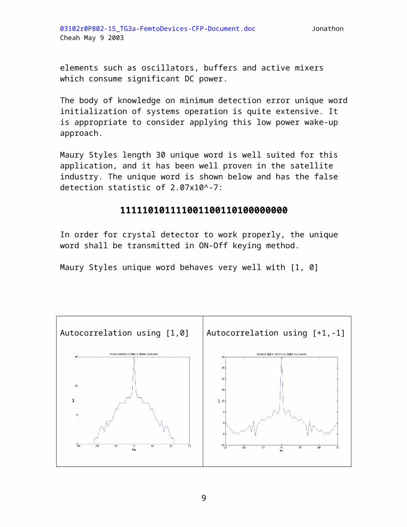
Maury Styles length 30 unique word is well suited for this application, and it has been well proven in the satellite industry. The unique word is shown below and has the false detection statistic of 2.07x10^-7:
111110101111001100110100000000
In order for crystal detector to work properly, the unique word shall be transmitted in ON-Off keying method.
Maury Styles unique word behaves very well with [1, 0]
Autocorrelation using [1,0] Autocorrelation using [+1,-1]
6

03102r0P802-15_TG3a-FemtoDevices-CFP-Document.doc Jonathon Cheah May 9 2003
7. The Receiver Chain
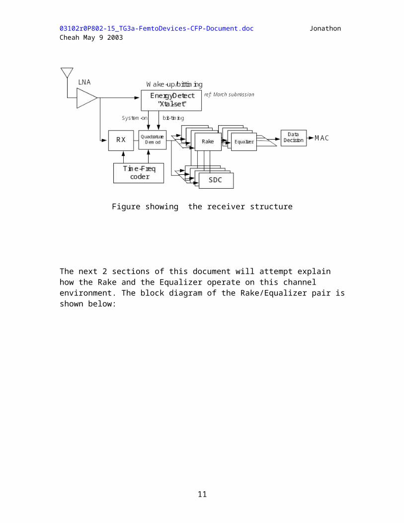
Consolidating all the concepts together, the receiver consists of a RF receiver that presents a baseband BPSK signal to the BPSK demodulator. Energy detection crystal set is used to wake up the receiver chain whenever there is a probable UWB transmitted signal to be detected. The design of the crystal set detector is very well known. Indeed, the modern day traffic radar detectors are still using a similar design, and a description for crystal detection can be found in doc. 03101r0P802-15_TG3a-femtoDevices-CFP-Document.doc [1].
The design of the BPSK demodulation can only be done in the analog domain due to the extremely high frequency of the UWB. Using digital technique on the front end would be inconceivable within the current DSP technology. However the analog Silicon implementation of BPSK and QPSK demodulation required here had been demonstrated before up to 20 Mbps [2] and it can be easily seen that the technology does not have any foreseeable technical impediments when it is extended to hundreds of Mhz range.
The backend Rake fingers and decision feedback equalizers have received considerable thoughts and considerations. These are elements that are potential complicated to implement, and therefore should be used in the simplest and the most effective manner. Any hints of over extending the design complexity would spell a possible death knell to the success of the UWB market. This is an area where other technology has suffered the unpleasant consequences over zealous in the application of digital communications complexity, and the lesson must be learnt.
7

03102r0P802-15_TG3a-FemtoDevices-CFP-Document.doc Jonathon Cheah May 9 2003
Figure showing the receiver structure
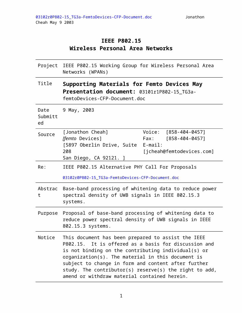
The next 2 sections of this document will attempt explain how the Rake and the Equalizer operate on this channel environment. The block diagram of the Rake/Equalizer pair is shown below:
Figure showing the detail configuration of the Rake receiver and the Equalizer.
8
03102r0P802-15_TG3a-FemtoDevices-CFP-Document.doc Jonathon Cheah May 9 2003
8. Rake Receiver
In the implementation of the Rake receiver, it is assumed that 10 PN sequences of length 31 is transmitted per channel are necessary to estimate the multipath coefficients and delays.
Each of the 10 PN sequences are assumed to be independent and uncorrelated, such that:
Multipath delays are estimated using a Swept Delay Correlator (SDC). SDC provides the multipath amplitude and delay coefficients.
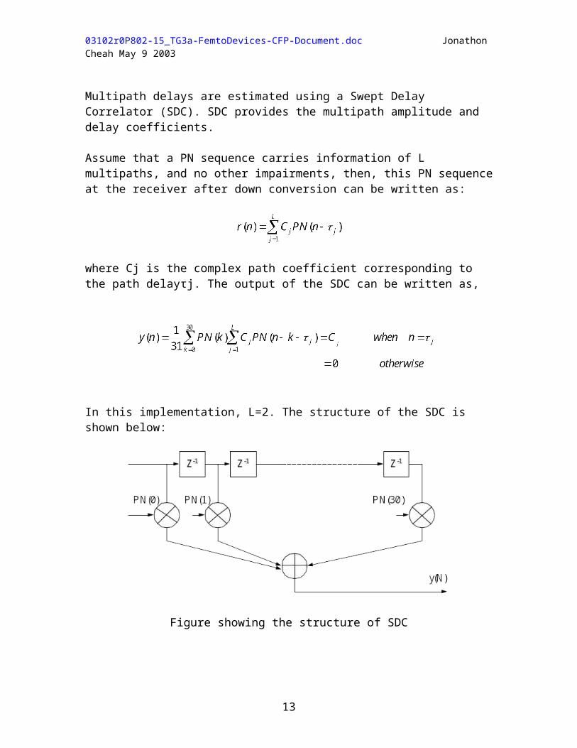
Assume that a PN sequence carries information of L multipaths, and no other impairments, then, this PN sequence at the receiver after down conversion can be written as:
where Cj is the complex path coefficient corresponding to the path delayτj. The output of the SDC can be written as,
In this implementation, L=2. The structure of the SDC is shown below:
9

03102r0P802-15_TG3a-FemtoDevices-CFP-Document.doc Jonathon Cheah May 9 2003
Figure showing the structure of SDC
The amplitude and delay coefficients, and respectively, are the fed to the Rake fingers. There are only 2 Rake fingers. It was determined that 2 Rake fingers are sufficient to combat the multipath effect if a PRF rate of ¼ for 2 nsec pulse width is used, ie: a 6 nsec time gap and 8 nsec repetitive time period.
The most simple structure of the Rake finger is used as shown below:
Figure showing the Rake structure.
8. Equalizer
The output of the Rake receiver is fed to the Equalizer which consists of a feed forward filter and a decision feedback filters. The equalizer is trained with a PN sequence that is 500 bits long. The equalizer used is a basic textbook adaptive MMSE equalizer.
10
03102r0P802-15_TG3a-FemtoDevices-CFP-Document.doc Jonathon Cheah May 9 2003
The Equalizer structure is shown below:
Figure showing the block diagram of the DFE
The M feed forward taps and N feedback taps are related in the following manner using M=16 and N=16:
Finally, in a graphical form, the following series of figures traces through the receive chain:
1. The CM1 channel 1 impulse response2. Resultant signal passing through the channel3. Multi-path complex real and imaginary signals.4. SDC resolvable paths with Cj and τj values extracted from the previous diagram.5. Equalizer convergence trajectory
11

03102r0P802-15_TG3a-FemtoDevices-CFP-Document.doc Jonathon Cheah May 9 2003
6. Resultant BPSK constellation after Rake receiver and equalization.
1 2
3 4
5 6
9. Mode of Operation
Now, the ability of the receiver to receive signal through the fading channel is established, a summary of how the system should work is provided here.
12
03102r0P802-15_TG3a-FemtoDevices-CFP-Document.doc Jonathon Cheah May 9 2003
The receiver is off by default at all times. Only the crystal detector is on. By good implementation technique, the resultant standby current should be very small, a wild guess based on radar detector design, this number should less than few mA. This is to power the LNA, and the LO at a fixed listening channel. It is also possible that individual built-in channel filter bank can provide a LO-less operation as presented in [1]
3 Maury-Styles unique words are sent to wake-up the main receiver through crystal detector activation.
10 concatenated length 31 M-sequence are sent per channel followed by a length 500 equalizer training sequence.
Now the receiver is ready to accept user data packets. The time-frequency coder is controlled by MAC, and any interference and NII
coexistence can be directly controlled by Time-Frequency coder, as it has direct control over the scheduling of the channel hopping sequences.
10. Channel Response Performance
The complexity and the length of the computing time make it very difficult to cover the required simulation.
A full simulation run on Matlab for 1 channel, 1 SNR point for a 1000 byte packet would take between 4 to 6 hours for a 2 Ghz Pentium processor, if it does not crash in the meantime. A significant number spot checks was conducted, and by no means meet the requirements set by the IEEE committee.
As a compromise, a stripped down version of the Matlab code can be provided on request so that reader who wishes to check the validity of the systems can do so. A C code version is being developed to cut down the simulation time.
So far the available data shows:
13

03102r0P802-15_TG3a-FemtoDevices-CFP-Document.doc Jonathon Cheah May 9 2003
10. Link Budget
Given that the required SNR is about 11 dB for BPSK before convolutional coding gain, then the required link budget can be constructed.
There is a 10.7dB path loss difference between 3.1 Ghz and 10.6 Ghz. Therefore transmission on the top band will have to be compensated by this amount for the link to be balanced.
Although there are a number of ways compensation can be made, however, an optimum solution with minimum cost objective is still being studied. At this point, high channel numbers at 480 Mbps is below link margin, and can only operate at 3 meter range.
Ch1 Ch8 Ch1 Ch8Throughput 100 100 480 480Over-the-air bit rate 275 275 1320 1320PRF rate 11 11 11 11Average TX power (PT) dBm -3.5 -0.5 0 0Tx Antenna gain (GT) dBi 0 0 0 0fc: center frequency of waveform Ghz 4.0 9.6 4.0 9.6Path loss at 1 meter (L1) dB 44.5 52.1 44.5 52.1Path loss at d meter (L2) dB 20 20 20 20Rx antenna gain (GR) dBi 0 0 0 0Rx Power (PR = PT+GT+GR-L1-L2) dBm -68 -72.6 -64.6 -72.2Noise bandwidth at antenna port (Mhz) 800 800 800 800Noise Power (N = -174 + 10*log(Rb)) dBm -89.6 -89.6 -82.8 -82.8Rx Noise Figure (NF) dB 7 7 7 7Rx Noise Power (PN = N+NF) dBm -82.6 -82.6 -75.8 -75.8Processing Gain (PG) 1 1 1 1Minimum C/N (S) dB 6 6 6 6
14

03102r0P802-15_TG3a-FemtoDevices-CFP-Document.doc Jonathon Cheah May 9 2003
Link Margin (M = PR + PG –PN- S) 5.6 1.0 2.2 -5.4Proposed Minimum Rx sensitivity level dBm -75 -75 -75 -75
The Link budget is calculated using a simple MathCad script as below, this is provided for the convenience of the reader who wishes to calculate other channel numbers or operational conditions:_____________________________________________________________________
15
030505aUWB Link Budget ref: 02490r0P802-15_SG3a-Channel-Modeling-Subcommittee-Report-Final.doc
Throughput Rb 1320106
channel frequency fc 4 109
channel BW(10dB) Cbw 2 Rb( ) 2.Rb 1200106if
4 Rb( ) fc 6.4 109 2. Rb 1200106if
1200106 otherwise
distance d 10
band repetition rate PRF 11
Average TX power Pt 41.3 10 log Cbw 10 6
TX power reduction Pprf 10log PRF( )
Total average TX power Pavg Pt Pprf
TX gain Gt 0Pavg 0.094RX gain Gr 0
Eb/No S 10Path loss 1 m L1 20 log4 fc
3 108
Implementation Loss I 3
Convolution Rate 1/2 C 4Path Loss L2 20 log d( )
RX power Pr Pavg Gt Gr L1 L2
Pr 64.577
Average Noise per bit N 174 10 log Rb( ) N 82.794
Noise Figure Nf 7 Pr 64.577
Pn N Nf Pn 75.794
Margin M Pr Pn S I C
M 2.217

03102r0P802-15_TG3a-FemtoDevices-CFP-Document.doc Jonathon Cheah May 9 2003
11. Reference:
[1] doc. 03101r0P802-15_TG3a-femtoDevices-CFP-Document.doc[2] J. Y. C. Cheah, “Practical Wireless Data Modem Design”, Artech House, 1999.
16