Embed Size (px)
Citation preview
Manifold Dual ContouringScott Schaefer, Tao Ju, and Joe Warren
Abstract—Dual Contouring (DC) is a feature-preserving isosurfacing method that extracts crack-free surfaces from both uniform and
adaptive octree grids. We present an extension of DC that further guarantees that the mesh generated is a manifold even under
adaptive simplification. Our main contribution is an octree-based topology-preserving vertex-clustering algorithm for adaptive
contouring. The contoured surface generated by our method contains only manifold vertices and edges, preserves sharp features, and
possesses much better adaptivity than those generated by other isosurfacing methods under topologically safe simplification.
Index Terms—Isosurfacing, contour simplification, vertex clustering, manifold.
Ç
1 INTRODUCTION
CONTOURING is the process of generating a piecewiselinear approximation to the zero-surface of an implicit
function. Originally motivated by the need for visualizing3D medical images, the study of contouring methods hasdeveloped into a major area in the field of graphics andvisualization. A large number of these methods aredesigned for volumes with a uniform grid structure. Forexample, the Marching Cubes (MC) method [1] generates aclosed manifold triangular mesh for any signed volume. Toimprove the quality of the contour geometry, methods likethe Extended MC [2] have been proposed to reproducesharp edges and corners by utilizing additional informationin the volume such as surface normals.
When the volume size is large, however, contouring on auniform grid may generate too many polygons forvisualization or further processing. To address this defi-ciency, Ju et al. [3] introduced the Dual Contouring (DC)method for generating adaptive contours. The DC methodsimplifies a uniform grid into an octree structure bymerging grid cells in which the underlying contourgeometry is flat. DC always produces crack-free contourson any octree grid and is also capable of reproducing sharpgeometry features when Hermite data is available. Incontrast, extending MC and its variants onto octree gridsoften results in cracks between the surface extracted fromadjacent octree cells at different octree depths, which needto be resolved using special crack-patching strategies suchas in [4] and [5].
Despite being adaptive and feature preserving, a majordrawback of the DC method is that, unlike MC and manyother uniform contouring methods, DC may generate
nonmanifold surfaces. That is, an edge on the contourmay be shared by more than two polygons, and theneighborhood of a vertex may not be topologicallyequivalent to a disk. Nonmanifold surfaces are not onlyless visually appealing than 2-manifolds, but also proble-matic for mesh processing tasks such as fairing andparameterization.
1.1 Contributions
In this paper, we propose an extension of the DC methodthat also guarantees production of manifold contours.Although there have been several variants of DC [6], [7]that introduce better topology control or even claim toproduce manifold contours, nonmanifold edges and ver-tices can still appear in the adaptive setting (see Section 2).In contrast, we present theoretical proofs that our methodalways generates closed 2-manifold surfaces even underadaptive simplification. Our method presents two noveladditions to the original DC method:
. A vertex clustering algorithm for contour simplifica-tion that allows multiple contour components in oneoctree cell. Compared to previous adaptive variantsof DC [7], [8], [9], our method is simpler toimplement and places no limit on the number ofintersections between the contour and each cell edge,hence allowing less restrictive simplification.
. A simple topology constraint in vertex clustering,which guarantees that the simplified contours arealways 2-manifold. To the best of our knowledge,this is the first manifold-preserving criterion devel-oped for octree-based vertex-clustering methods.
2 RELATED WORK
In this section, we briefly review the DC method, recentextensions and variants of DC, related mesh simplificationmethods using vertex clustering, and other approaches fortopology-preserving contour simplification.
2.1 DC
The DC method, proposed by Ju et al. [3], provides a uniformapproach for extracting water-tight isosurfaces on bothuniform grids and adaptive octree grids. The algorithm
IEEE TRANSACTIONS ON VISUALIZATION AND COMPUTER GRAPHICS, VOL. 13, NO. 3, MAY/JUNE 2007 1
. S. Schaefer is with the Department of Computer Science, 3112 Texas A&MUniversity, College Station, TX 77843-3112.E-mail: [email protected].
. T. Ju is with the Department of Computer Science and Engineering,Washington University in St. Louis, One Brookings Drive, Campus Box1045, St. Louis, MO 63130. E-mail: [email protected].
. J. Warren is with the Department of Computer Science, 6100 South Main,Rice University, Houston, TX 77251-1892. E-mail: [email protected].
Manuscript received 26 Aug. 2006; accepted 13 Nov. 2006; published online 8Jan. 2007.For information on obtaining reprints of this article, please send e-mail to:[email protected], and reference IEEECS Log Number TVCG-0137-0806.Digital Object Identifier no. 10.1109/TVCG.2007.1012.
1077-2626/07/$25.00 � 2007 IEEE Published by the IEEE Computer Society
creates one vertex for each grid cell that contains a sign changeand creates the surface by generating one polygon for everyedge in the grid containing a sign change. Along each sign-change edge, the polygon connects the four vertices of thecells sharing that edge. DC guarantees to generate a closesurface on any octree grid and can be implemented efficientlyusing recursive tree traversals [3].
Another advantage of DC over MC is its ability toreproduce sharp features such as edges and corners whenHermite data is available. In Hermite representation, eachgrid edge that contains a sign change is associated with anintersection point between the contour and the edge, as wellas a normal vector of the contour at the point. Such Hermiterepresentation can either be obtained from a closedtriangular mesh [10] or directly from an implicit function.In DC, the vertex within a cell is placed so as to minimize aQuadratic Error Function (QEF) [11] constructed from theHermite data associated with the cell edges.
2.2 Extensions and Variants of DC
A problem of DC that has been of common interest inalmost all subsequent work is the restriction of DC inmaintaining no more than one contour vertex within eachgrid cell. To relax this restriction on a uniform grid,multiple contour components in a cell can be detectedeither by identifying edge-connected components of posi-tive (or negative) cell corners [9], [12] or by utilizing thecycles in the MC lookup table [7], [13]. In this paper, wefollow the Dual MC approach of Nielson [13] to obtain onevertex for each contour component on the uniform grid (seedetails in Section 3).
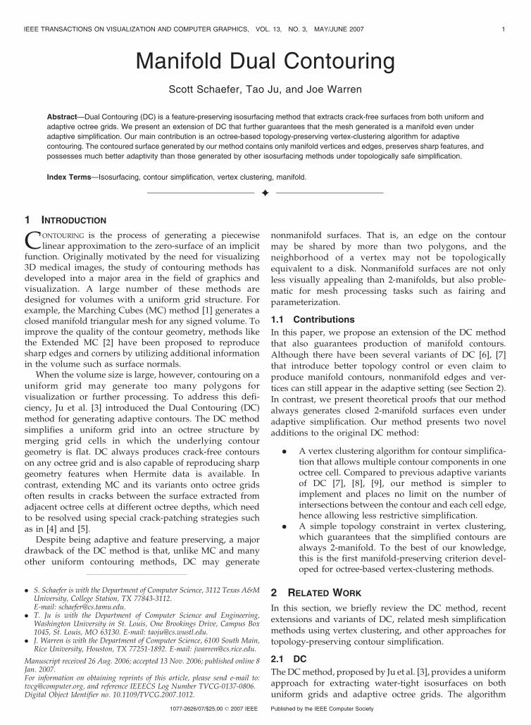
To handle multiple vertices per cell in adaptive contour-ing, Zhang et al. [7] propose a vertex-clustering approachfor simplifying contours. Their method maintains thedisconnected contour components during simplificationusing an enhanced cell representation and results in muchbetter adaptivity than DC. However, preserving compo-nents alone is not sufficient to avoid nonmanifold verticesor edges. Fig. 1 shows an example in which the method ofZhang et al. [7] would generate a nonmanifold edge whenvertex clustering is performed in two neighboring octreecells containing a cylinder-shaped surface. Moreover,contour simplification in [7] requires nontrivial coding-vector operations and is restricted to a maximum of twointersections between the contour and each cell edge. Suchrestriction places a bound on the maximum number ofcontour patches that an octree cell may contain, resulting inlimited simplification of complex contours (see an example
in Section 6). A similar restriction is also found in themethod of Varadhan et al. [9], which creates an adaptivegrid using octree refinement guided by feature detection.
Instead of contour simplification, the method of Ashidaand Badler [6] extracts contours directly from octrees withadaptive resolution. Their method identifies cycles ofcontour faces intersecting each octree cell and creates onevertex for each cycle. Despite their claim of a manifoldcontour, nonmanifold contour edges may still appearbetween two neighboring cells, such as in the cylinderexample of Fig. 1b. Moreover, cycle identification is a time-consuming process. In a completely different approach,Schaefer and Warren [8] extract contours by performing MCon a hexahedral grid dual to the octree grid, which isgenerated by extending DC to volumetric functions. Theresulting surface is guaranteed to be a 2-manifold but isvery expensive to compute.
2.3 Vertex Clustering
Contour simplification in DC and its variants is closelyrelated to vertex clustering methods for simplifying poly-gonal meshes. These methods group vertices based onspatial or geometric proximity and compute one represen-tative vertex for all vertices in a same group. Vertexgrouping often utilizes some type of spatial partitioningstructure such as uniform cubic grids [14], floating cells [15],octree grids [16], and binary space partitioning (BSP) trees[17]. As in DC, QEFs can be used for accurate placement ofrepresentative vertices [18], [19]. However, little work hasbeen done in controlling topology during vertex clustering.Brodsky and Watson [20] perform a topology check thatpartitions a group of vertices if the group contains disjointcomponents. Similarly, Kanaya et al. [21] compute onerepresentative vertex for each connected component in eachvertex group to preserve disjoint portions of a mesh. Todate, there has been no report of any octree-based vertex-clustering method that preserves the manifoldness or genusof the surface.
2.4 Topology-Preserving Contour Simplification
Besides the octree-based vertex-clustering approach in DCand its variants, there are several other contour simplifica-tion methods, some of which preserve surface topologyduring simplification. Lewiner et al. [22] presented anisosurface compression method on a simplicial (for exam-ple, triangular or tetrahedral) grid via simplificationoperators, known as “welds,” that are applied to the grid.The compression preserves isosurface topology and man-ifoldness by checking the Euler characteristic of the surfaceportion affected by each weld. However, such a test iscomputationally expensive as the fine isosurface has to becomputed locally prior to each weld.
Another approach for contour simplification is tocontour a uniform grid first and then simplify the resultingisosurface using a mainstream mesh simplification techni-que such as [23] or [11]. In contrast to DC and its variants,which apply grid simplification first and then contour, thissecond approach can be much more time and spaceconsuming due to the need to generate and store a finepolygonal isosurface prior to mesh simplification.
2 IEEE TRANSACTIONS ON VISUALIZATION AND COMPUTER GRAPHICS, VOL. 13, NO. 3, MAY/JUNE 2007
Fig. 1. (a) Vertex clustering in two neighboring cells results in (b) a
nonmanifold edge on the surface.
To reduce the high cost of the contour-and-simplifyapproach, Attali et al. [24] proposed a hybrid approachwhere a fine isosurface is formed and immediatelysimplified as each slice of the grid is processed. Theisosurface is contoured using MC and simplification isbased on edge contractions on the polygonal surface. Byenforcing the “link conditions” proposed by Dey et al. [25]during simplification, the simplified surface is alwaysmanifold and the topology of the original isosurface ispreserved. Although Attali et al.’s method avoids storingthe entire fine-level isosurface, the speed of the methodremains slow since this fine surface still needs to begenerated and then simplified. As we will see, ourtopology-preserving modification to DC simplifies anisosurface in much less time since no polygon is generateduntil after the grid is simplified.
3 CONTOURING ON A UNIFORM GRID
We start by describing a simple modification, first proposedby Nielson [13], to the original DC algorithm [3]. One of thelimitations of DC is that it allows no more than one vertexwithin each grid cell. On a uniform grid, DC leads tononmanifold vertices and edges for all of the ambiguoussign configurations in the original MC algorithm [1].
To combat this effect, Nielson’s modification allowsmultiple vertices to be placed in a single cell. In particular,Nielson associates one vertex with each cycle of a modifiedMC table [26]. Since each cycle consists of a list of edges onthe cubic cell, each vertex is associated with a set of edges,and each edge is associated with exactly one vertex. Tocreate polygons, the algorithm constructs one polygonconnecting the vertices associated with that edge in thefour adjacent cells. This algorithm creates a quadrilateralsurface that is the dual of the surface created using MC (andwas therefore given the name “Dual MC”). Furthermore,this surface is always a manifold because the original MCalgorithm always constructs a manifold and the dualpreserves the topology of the surface.
One of the advantages of DC over a traditional contouringmethod such as MC is its capability of reproducing sharpfeatures in the presence of Hermite data. To incorporateHermite data into Nielson’s Dual MC algorithm, we simplyconstruct a QEF [11] for each vertex using the Hermite data onthe edges associated with that vertex. We place this vertex atthe location that minimizes that error function.
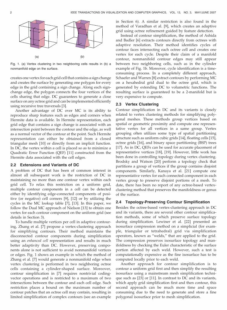
Fig. 2 shows a comparison in 2D of the different methods.MC always produces a manifold, but does not reproducesharp features. DC reproduces sharp features, but thetopology may be nonmanifold in some configurations. TheHermite extension to Dual MC always produces a topologicalmanifold and can reproduce sharp features as well.
4 ADAPTIVE CONTOURING
In Section 3, we considered constructing manifold isosur-faces from uniform grids that preserve sharp features.However, for models with relatively flat regions, theuniform contouring algorithm produces a large number ofpolygons covering these flat regions. Ideally, the contouringalgorithm would extract a surface where the number of
polygons adapts to the local properties of the surface (thatis, fewer polygons in flat regions).
DC provides such an algorithm to construct multi-resolution isosurfaces. The method essentially performsvertex clustering where the vertices of the child cells in theoctree collapse to a single vertex in a topologically safemanner. However, since only one vertex was allowed percell in DC, the collapse was very restrictive. Here, wedevelop a new contour simplification method via octree-based vertex clustering, which allows for an arbitrarynumber of vertices per cell. Furthermore, we describe apolygon generation algorithm for constructing surfacesfrom these adaptively clustered vertices.
4.1 Vertex Clustering
Given an error threshold, the vertex-clustering phasecreates a vertex tree starting with the vertices at the finestlevel of the octree. Each vertex contains a parent pointer, aswell as the QEF associated with this vertex and the value ofthe QEF evaluated at this vertex (that is, the error associatedwith this vertex). Furthermore, a vertex is marked as beingcollapsible if the error associated with the vertex is less thanour given threshold. Initially, we flag all vertices ascollapsible and set their parent indices to null.
When simplifying the octree, we only cluster verticestogether that are topologically connected on the surface.Note that this approach is similar to that of Zhang et al. [7],but it is not sufficient to guarantee that we maintain themanifold properties of the surface under simplification (thiswill be addressed in Section 5).
Our method traverses the octree cells in a bottom-upmanner. For each octree cell that is not a leaf, we considerits eight children. These children have 12 faces that areinternal to their parent cell (four for each of the euclideanaxes). We cluster together vertices at the root of the vertextree that are topologically connected by edges dual to the12 internal faces. The recursive octree traversal algorithm in
SCHAEFER ET AL.: MANIFOLD DUAL CONTOURING 3
Fig. 2. Comparison of contouring with Hermite data. (a) Cell with Hermite
data on edges, (b) MC, (c) DC, and (d) Hermite Dual MC.
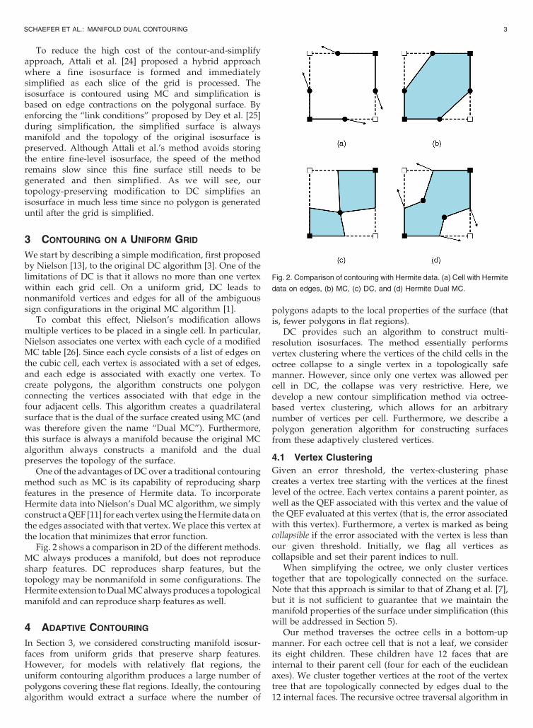
[3] provides an efficient technique for finding all of theseedges. For each group, we cluster the vertices together bycombining their QEFs and minimizing the error function tofind the new vertex location, as well as the error associatedwith this new vertex. If the error for this vertex is less thanthe threshold, we mark the new vertex as collapsible.
Fig. 3 shows a 2D illustration of this algorithm. Here, aquadtree has four children, and we cluster vertices togetherthat are connected by edges through the four internal gridedges. The vertex trees (see Fig. 3c) are maintainedindependent of the actual octree. If we compare ourapproach with that of Zhang et al. [7], which builds avertex tree by merging “coding vectors” associated withvertices, we can maintain similar topological connectivitywithout resorting to complex coding for each vertex insideof the cell. Also, we can handle an arbitrary number ofintersections per edge, whereas other methods [7], [8], [9]restrict the number of intersections to two.
Note that, so far, we permit a surface of arbitrarilycomplex topology to be clustered into a single vertex, whichmay yield nonmanifold topology after clustering. We willresolve this deficiency in Section 5 by introducing anadditional topology criterion for collapsible vertices, whichwill restrict clustering to surfaces with simple topology (forexample, a sheet) within each cell.
4.2 Polygonalization
After the vertex clustering stage, we construct polygons thatconnect these vertices together. The vertices included in theoutput mesh will be those vertices marked as beingcollapsible that do not have any collapsible ancestors inthe tree.
To construct polygons, we follow the uniform contouringalgorithm and create a polygon connecting the verticesassociated with each edge that exhibits a sign change. Foreach of those vertices, we follow the parent pointers up thevertex tree to find the last vertex marked as beingcollapsible. If the resulting polygon collapses to an edgeor a vertex, then we discard that polygon and continue.
To enumerate these edges, we use the recursive algo-rithm detailed by Ju et al. [3], which traverses the octree andcollects the octree cells adjacent to each of the edges. Theiralgorithm involves three types of functions that enumeratethe cells, faces, and edges of the octree along with theiradjacent octree cells, namely, cellProc, faceProc, andedgeProc. For further details, we refer the reader to theirpaper.
One disadvantage of the above algorithm is that itrequires a traversal of the entire octree even after vertexclustering has collapsed the vertices. To optimize thisalgorithm, we mark a cell during the clustering algorithmas “collapsed” if all clustered vertices created in that cellsatisfy the collapsible criterion and all of the children of thatcell are either leaf cells or marked as collapsed. If a cell iscollapsed, then none of the children cell in this octree cellcreate any polygons, and we can truncate the octreetraversal (cellProc) when it encounters a collapsed cell.Furthermore, we can truncate the faceProc traversal on aface if both cells sharing the face are collapsed cells becauseno polygons corresponding to the shared face will begenerated.
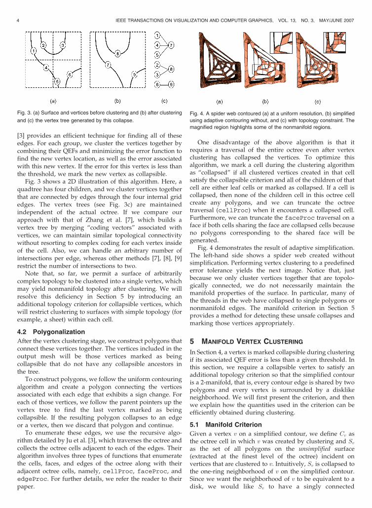
Fig. 4 demonstrates the result of adaptive simplification.The left-hand side shows a spider web created withoutsimplification. Performing vertex clustering to a predefinederror tolerance yields the next image. Notice that, justbecause we only cluster vertices together that are topolo-gically connected, we do not necessarily maintain themanifold properties of the surface. In particular, many ofthe threads in the web have collapsed to single polygons ornonmanifold edges. The manifold criterion in Section 5provides a method for detecting these unsafe collapses andmarking those vertices appropriately.
5 MANIFOLD VERTEX CLUSTERING
In Section 4, a vertex is marked collapsible during clusteringif its associated QEF error is less than a given threshold. Inthis section, we require a collapsible vertex to satisfy anadditional topology criterion so that the simplified contouris a 2-manifold, that is, every contour edge is shared by twopolygons and every vertex is surrounded by a disklikeneighborhood. We will first present the criterion, and thenwe explain how the quantities used in the criterion can beefficiently obtained during clustering.
5.1 Manifold Criterion
Given a vertex v on a simplified contour, we define Cv asthe octree cell in which v was created by clustering and Svas the set of all polygons on the unsimplified surface(extracted at the finest level of the octree) incident onvertices that are clustered to v. Intuitively, Sv is collapsed tothe one-ring neighborhood of v on the simplified contour.Since we want the neighborhood of v to be equivalent to adisk, we would like Sv to have a singly connected
4 IEEE TRANSACTIONS ON VISUALIZATION AND COMPUTER GRAPHICS, VOL. 13, NO. 3, MAY/JUNE 2007
Fig. 3. (a) Surface and vertices before clustering and (b) after clustering
and (c) the vertex tree generated by this collapse.
Fig. 4. A spider web contoured (a) at a uniform resolution, (b) simplified
using adaptive contouring without, and (c) with topology constraint. The
magnified region highlights some of the nonmanifold regions.
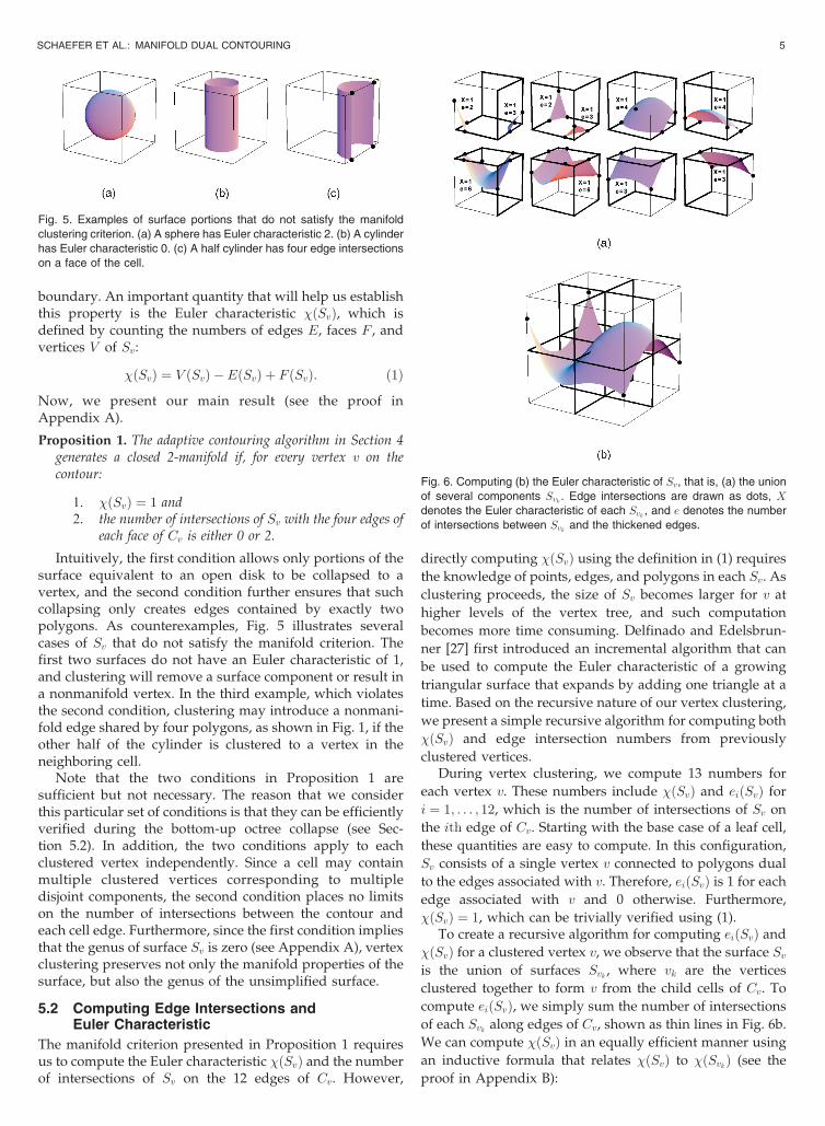
boundary. An important quantity that will help us establishthis property is the Euler characteristic �ðSvÞ, which isdefined by counting the numbers of edges E, faces F , andvertices V of Sv:
�ðSvÞ ¼ V ðSvÞ �EðSvÞ þ F ðSvÞ: ð1Þ
Now, we present our main result (see the proof inAppendix A).
Proposition 1. The adaptive contouring algorithm in Section 4generates a closed 2-manifold if, for every vertex v on thecontour:
1. �ðSvÞ ¼ 1 and2. the number of intersections of Sv with the four edges of
each face of Cv is either 0 or 2.
Intuitively, the first condition allows only portions of thesurface equivalent to an open disk to be collapsed to avertex, and the second condition further ensures that suchcollapsing only creates edges contained by exactly twopolygons. As counterexamples, Fig. 5 illustrates severalcases of Sv that do not satisfy the manifold criterion. Thefirst two surfaces do not have an Euler characteristic of 1,and clustering will remove a surface component or result ina nonmanifold vertex. In the third example, which violatesthe second condition, clustering may introduce a nonmani-fold edge shared by four polygons, as shown in Fig. 1, if theother half of the cylinder is clustered to a vertex in theneighboring cell.
Note that the two conditions in Proposition 1 aresufficient but not necessary. The reason that we considerthis particular set of conditions is that they can be efficientlyverified during the bottom-up octree collapse (see Sec-tion 5.2). In addition, the two conditions apply to eachclustered vertex independently. Since a cell may containmultiple clustered vertices corresponding to multipledisjoint components, the second condition places no limitson the number of intersections between the contour andeach cell edge. Furthermore, since the first condition impliesthat the genus of surface Sv is zero (see Appendix A), vertexclustering preserves not only the manifold properties of thesurface, but also the genus of the unsimplified surface.
5.2 Computing Edge Intersections andEuler Characteristic
The manifold criterion presented in Proposition 1 requiresus to compute the Euler characteristic �ðSvÞ and the numberof intersections of Sv on the 12 edges of Cv. However,
directly computing �ðSvÞ using the definition in (1) requires
the knowledge of points, edges, and polygons in each Sv. As
clustering proceeds, the size of Sv becomes larger for v at
higher levels of the vertex tree, and such computation
becomes more time consuming. Delfinado and Edelsbrun-
ner [27] first introduced an incremental algorithm that can
be used to compute the Euler characteristic of a growing
triangular surface that expands by adding one triangle at a
time. Based on the recursive nature of our vertex clustering,
we present a simple recursive algorithm for computing both
�ðSvÞ and edge intersection numbers from previously
clustered vertices.During vertex clustering, we compute 13 numbers for
each vertex v. These numbers include �ðSvÞ and eiðSvÞ for
i ¼ 1; . . . ; 12, which is the number of intersections of Sv on
the ith edge of Cv. Starting with the base case of a leaf cell,
these quantities are easy to compute. In this configuration,
Sv consists of a single vertex v connected to polygons dual
to the edges associated with v. Therefore, eiðSvÞ is 1 for each
edge associated with v and 0 otherwise. Furthermore,
�ðSvÞ ¼ 1, which can be trivially verified using (1).To create a recursive algorithm for computing eiðSvÞ and
�ðSvÞ for a clustered vertex v, we observe that the surface Svis the union of surfaces Svk , where vk are the vertices
clustered together to form v from the child cells of Cv. To
compute eiðSvÞ, we simply sum the number of intersections
of each Svk along edges of Cv, shown as thin lines in Fig. 6b.
We can compute �ðSvÞ in an equally efficient manner using
an inductive formula that relates �ðSvÞ to �ðSvkÞ (see the
proof in Appendix B):
SCHAEFER ET AL.: MANIFOLD DUAL CONTOURING 5
Fig. 5. Examples of surface portions that do not satisfy the manifold
clustering criterion. (a) A sphere has Euler characteristic 2. (b) A cylinder
has Euler characteristic 0. (c) A half cylinder has four edge intersections
on a face of the cell.
Fig. 6. Computing (b) the Euler characteristic of Sv, that is, (a) the union
of several components Svk . Edge intersections are drawn as dots, X
denotes the Euler characteristic of each Svk , and e denotes the number
of intersections between Svk and the thickened edges.
�ðSvÞ ¼X
k
�ðSvkÞ �P
k eðSvkÞ4
; ð2Þ
where eðSvkÞ denotes the sum of the number of intersectionsof Svk along the internal edges of Cv, shown as thickenedlines in Fig. 6b.
Fig. 6b shows an example where Sv is built from10 surfaces Svk (Fig. 6a). For each child cell, we displaythe quantities �ðSvkÞ and eðSvkÞ for each Svk in Fig. 6a.Observe that
Pk �ðSvkÞ ¼ 10 and
Pk eðSvkÞ ¼ 36 and, hence,
�ðSvÞ ¼ 1 by (2), which is the correct Euler characteristic ofthe disklike surface Sv.
To integrate the topology constraint into the adaptivecontouring algorithm in Section 4, we require that a vertex vis collapsible if the associated QEF error is below the giventhreshold and if eiðSvÞ and �ðSvÞ satisfy the two conditionsin Proposition 1. Fig. 4c shows the result of adaptivecontouring with topology constraint, which preserves allthe threads of the spider web with manifold vertices andedges.
6 RESULTS
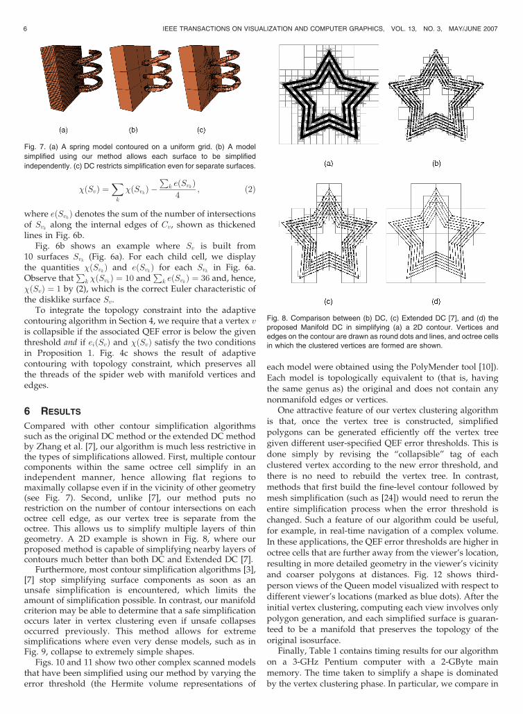
Compared with other contour simplification algorithmssuch as the original DC method or the extended DC methodby Zhang et al. [7], our algorithm is much less restrictive inthe types of simplifications allowed. First, multiple contourcomponents within the same octree cell simplify in anindependent manner, hence allowing flat regions tomaximally collapse even if in the vicinity of other geometry(see Fig. 7). Second, unlike [7], our method puts norestriction on the number of contour intersections on eachoctree cell edge, as our vertex tree is separate from theoctree. This allows us to simplify multiple layers of thingeometry. A 2D example is shown in Fig. 8, where ourproposed method is capable of simplifying nearby layers ofcontours much better than both DC and Extended DC [7].
Furthermore, most contour simplification algorithms [3],[7] stop simplifying surface components as soon as anunsafe simplification is encountered, which limits theamount of simplification possible. In contrast, our manifoldcriterion may be able to determine that a safe simplificationoccurs later in vertex clustering even if unsafe collapsesoccurred previously. This method allows for extremesimplifications where even very dense models, such as inFig. 9, collapse to extremely simple shapes.
Figs. 10 and 11 show two other complex scanned modelsthat have been simplified using our method by varying theerror threshold (the Hermite volume representations of
each model were obtained using the PolyMender tool [10]).Each model is topologically equivalent to (that is, havingthe same genus as) the original and does not contain anynonmanifold edges or vertices.
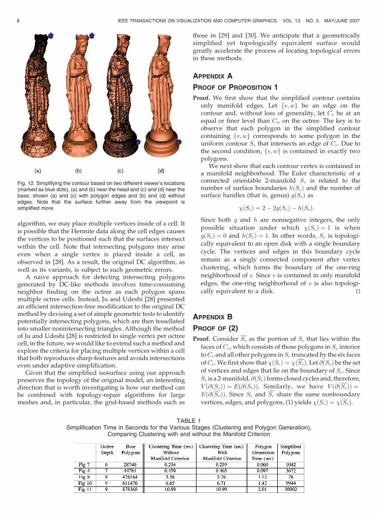
One attractive feature of our vertex clustering algorithmis that, once the vertex tree is constructed, simplifiedpolygons can be generated efficiently off the vertex treegiven different user-specified QEF error thresholds. This isdone simply by revising the “collapsible” tag of eachclustered vertex according to the new error threshold, andthere is no need to rebuild the vertex tree. In contrast,methods that first build the fine-level contour followed bymesh simplification (such as [24]) would need to rerun theentire simplification process when the error threshold ischanged. Such a feature of our algorithm could be useful,for example, in real-time navigation of a complex volume.In these applications, the QEF error thresholds are higher inoctree cells that are further away from the viewer’s location,resulting in more detailed geometry in the viewer’s vicinityand coarser polygons at distances. Fig. 12 shows third-person views of the Queen model visualized with respect todifferent viewer’s locations (marked as blue dots). After theinitial vertex clustering, computing each view involves onlypolygon generation, and each simplified surface is guaran-teed to be a manifold that preserves the topology of theoriginal isosurface.
Finally, Table 1 contains timing results for our algorithmon a 3-GHz Pentium computer with a 2-GByte mainmemory. The time taken to simplify a shape is dominatedby the vertex clustering phase. In particular, we compare in
6 IEEE TRANSACTIONS ON VISUALIZATION AND COMPUTER GRAPHICS, VOL. 13, NO. 3, MAY/JUNE 2007
Fig. 7. (a) A spring model contoured on a uniform grid. (b) A model
simplified using our method allows each surface to be simplified
independently. (c) DC restricts simplification even for separate surfaces.
Fig. 8. Comparison between (b) DC, (c) Extended DC [7], and (d) the
proposed Manifold DC in simplifying (a) a 2D contour. Vertices and
edges on the contour are drawn as round dots and lines, and octree cells
in which the clustered vertices are formed are shown.
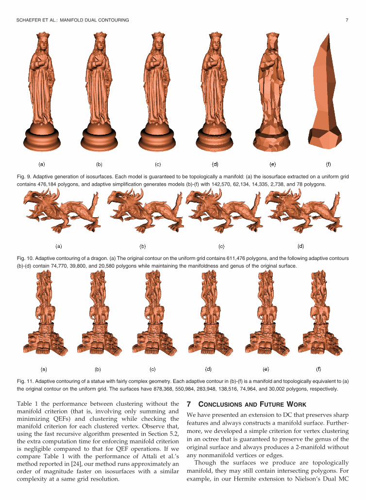
Table 1 the performance between clustering without themanifold criterion (that is, involving only summing andminimizing QEFs) and clustering while checking themanifold criterion for each clustered vertex. Observe that,using the fast recursive algorithm presented in Section 5.2,the extra computation time for enforcing manifold criterionis negligible compared to that for QEF operations. If wecompare Table 1 with the performance of Attali et al.’smethod reported in [24], our method runs approximately anorder of magnitude faster on isosurfaces with a similarcomplexity at a same grid resolution.
7 CONCLUSIONS AND FUTURE WORK
We have presented an extension to DC that preserves sharp
features and always constructs a manifold surface. Further-
more, we developed a simple criterion for vertex clustering
in an octree that is guaranteed to preserve the genus of the
original surface and always produces a 2-manifold without
any nonmanifold vertices or edges.Though the surfaces we produce are topologically
manifold, they may still contain intersecting polygons. For
example, in our Hermite extension to Nielson’s Dual MC
SCHAEFER ET AL.: MANIFOLD DUAL CONTOURING 7
Fig. 9. Adaptive generation of isosurfaces. Each model is guaranteed to be topologically a manifold: (a) the isosurface extracted on a uniform grid
contains 476,184 polygons, and adaptive simplification generates models (b)-(f) with 142,570, 62,134, 14,335, 2,738, and 78 polygons.
Fig. 10. Adaptive contouring of a dragon. (a) The original contour on the uniform grid contains 611,476 polygons, and the following adaptive contours
(b)-(d) contain 74,770, 39,800, and 20,580 polygons while maintaining the manifoldness and genus of the original surface.
Fig. 11. Adaptive contouring of a statue with fairly complex geometry. Each adaptive contour in (b)-(f) is a manifold and topologically equivalent to (a)
the original contour on the uniform grid. The surfaces have 878,368, 550,984, 283,948, 138,516, 74,964, and 30,002 polygons, respectively.
algorithm, we may place multiple vertices inside of a cell. Itis possible that the Hermite data along the cell edges causesthe vertices to be positioned such that the surfaces intersectwithin the cell. Note that intersecting polygons may ariseeven when a single vertex is placed inside a cell, asobserved in [28]. As a result, the original DC algorithm, aswell as its variants, is subject to such geometric errors.
A naive approach for detecting intersecting polygonsgenerated by DC-like methods involves time-consumingneighbor finding on the octree as each polygon spansmultiple octree cells. Instead, Ju and Udeshi [28] presentedan efficient intersection-free modification to the original DCmethod by devising a set of simple geometric tests to identifypotentially intersecting polygons, which are then tessellatedinto smaller nonintersecting triangles. Although the methodof Ju and Udeshi [28] is restricted to single vertex per octreecell, in the future, we would like to extend such a method andexplore the criteria for placing multiple vertices within a cellthat both reproduces sharp-features and avoids intersectionseven under adaptive simplification.
Given that the simplified isosurface using our approachpreserves the topology of the original model, an interestingdirection that is worth investigating is how our method canbe combined with topology-repair algorithms for largemeshes and, in particular, the grid-based methods such as
those in [29] and [30]. We anticipate that a geometricallysimplified yet topologically equivalent surface wouldgreatly accelerate the process of locating topological errorsin these methods.
APPENDIX A
PROOF OF PROPOSITION 1
Proof. We first show that the simplified contour containsonly manifold edges. Let fv; wg be an edge on thecontour and, without loss of generality, let Cv be at anequal or finer level than Cw on the octree. The key is toobserve that each polygon in the simplified contourcontaining fv; wg corresponds to some polygon in theuniform contour Sv that intersects an edge of Cv. Due tothe second condition, fv; wg is contained in exactly twopolygons.
We next show that each contour vertex is contained ina manifold neighborhood. The Euler characteristic of aconnected orientable 2-manifold Sv is related to thenumber of surface boundaries hðSvÞ and the number ofsurface handles (that is, genus) gðSvÞ as
�ðSvÞ ¼ 2� 2gðSvÞ � hðSvÞ:
Since both g and h are nonnegative integers, the onlypossible situation under which �ðSvÞ ¼ 1 is whengðSvÞ ¼ 0 and hðSvÞ ¼ 1. In other words, Sv is topologi-cally equivalent to an open disk with a single boundarycycle. The vertices and edges in this boundary cycleremain as a singly connected component after vertexclustering, which forms the boundary of the one-ringneighborhood of v. Since v is contained in only manifoldedges, the one-ring neighborhood of v is also topologi-cally equivalent to a disk. tu
APPENDIX B
PROOF OF (2)
Proof. Consider Sv as the portion of Sv that lies within thefaces of Cv, which consists of those polygons in Sv interiortoCv and all other polygons inSv truncated by the six facesofCv. We first show that�ðSvÞ ¼ �ðSvÞ. Let @ðSvÞ be the setof vertices and edges that lie on the boundary of Sv. SinceSv is a 2-manifold, @ðSvÞ forms closed cycles and, therefore,V ð@ðSvÞÞ ¼ Eð@ðSvÞÞ. Similarly, we have V ð@ðSvÞÞ ¼Eð@ðSvÞÞ. Since Sv and Sv share the same nonboundaryvertices, edges, and polygons, (1) yields �ðSvÞ ¼ �ðSvÞ.
8 IEEE TRANSACTIONS ON VISUALIZATION AND COMPUTER GRAPHICS, VOL. 13, NO. 3, MAY/JUNE 2007
Fig. 12. Simplifying the contour based on two different viewer’s locations(marked as blue dots), (a) and (b) near the head and (c) and (d) near thebase, shown (a) and (c) with polygon edges and (b) and (d) withoutedges. Note that the surface further away from the viewpoint issimplified more.
TABLE 1Simplification Time in Seconds for the Various Stages (Clustering and Polygon Generation),
Comparing Clustering with and without the Manifold Criterion
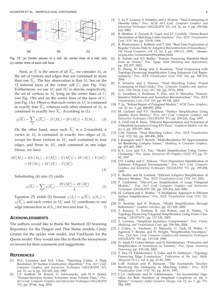
Next, as Sv is the union of all Svk , we consider Mv asthe set of vertices and edges that are contained in morethan one Svk . The key observation is that Mv lies on the12 internal faces of the octree cell Cv (see Fig. 13a).Furthermore, we use Mc
v and Mfv to denote, respectively,
the set of vertices in Mv lying on the center lines of Cv(see Fig. 13b) and on the center lines of the faces of Cv(see Fig. 13c). Observe that each vertex in Mc
v is containedin exactly four Svk , whereas each other element of Mv iscontained in exactly two Svk . According to (1):
�ðSvÞ ¼X
k
�ðSvkÞ � ðV ðMvÞ þ 2V ðMcvÞÞ þ EðMvÞ: ð3Þ
On the other hand, since each Svk is a 2-manifold, a
vertex in Mv is contained in exactly two edges of Mv
except for those vertices in Mcv , each contained in four
edges, and those in Mfv , each contained in one edge.
Hence, we have
2EðMvÞ ¼ 2ðV ðMvÞ � V ðMcvÞ � V ðMf
v ÞÞ þ 4V ðMcvÞ þ V ðMf
v Þ¼ 2V ðMvÞ þ 2V ðMc
vÞ � V ðMfv Þ:
ð4Þ
Substituting (4) into (3) yields
�ðSvÞ ¼X
k
�ðSvkÞ �2V ðMf
v Þ þ 4V ðMcvÞ
4: ð5Þ
Equation (5) yields (2) because �ðSvÞ ¼ �ðSvÞ, �ðSvkÞ ¼�ðSvkÞ, and each vertex in Mf
v and Mcv contributes to one
edge intersection in dðSvkÞ for two and four Svk . tu
ACKNOWLEDGMENTS
The authors would like to thank the Stanford 3D Scanning
Repository for the Dragon and Thai Statue models, Cindy
Grimm for the spider web model, and VanDuzan for the
Queen model. They would also like to thank the anonymous
reviewers for their comments and suggestions.
REFERENCES
[1] W.E. Lorensen and H.E. Cline, “Marching Cubes: A HighResolution 3D Surface Construction Algorithm,” Proc. Int’l Conf.Computer Graphics and Interactive Techniques (SIGGRAPH ’87),vol. 21, no. 4, pp. 163-169, July 1987.
[2] L.P. Kobbelt, M. Botsch, U. Schwanecke, and H.-P. Seidel,“Feature-Sensitive Surface Extraction from Volume Data,” Proc.Int’l Conf. Computer Graphics and Interactive Techniques (SIGGRAPH’01), pp. 57-66, Aug. 2001.
[3] T. Ju, F. Losasso, S. Schaefer, and J. Warren, “Dual Contouring ofHermite Data,” Proc. ACM Int’l Conf. Computer Graphics andInteractive Techniques (SIGGRAPH ’02), vol. 21, no. 3, pp. 339-346,July 2002.
[4] R. Shekhar, E. Fayyad, R. Yagel, and J.F. Cornhill, “Octree-BasedDecimation of Marching Cubes Surfaces,” Proc. IEEE VisualizationConf. (VIS ’96), pp. 335-ff, 1996.
[5] R. Westermann, L. Kobbelt, and T. Ertl, “Real-Time Exploration ofRegular Volume Data by Adaptive Reconstruction of Isosurfaces,”The Visual Computer, vol. 15, no. 2, pp. 100-111, 1999, citeseer.ist.psu.edu/westermann99realtime.html.
[6] K. Ashida and N.I. Badler, “Feature Preserving Manifold Meshfrom an Octree,” Proc. Symp. Solid Modeling and Applications,pp. 292-297, 2003.
[7] N. Zhang, W. Hong, and A. Kaufman, “Dual Contouring withTopology-Preserving Simplification Using Enhanced Cell Repre-sentation,” Proc. IEEE Visualization Conf. (VIS ’04), pp. 505-512,2004.
[8] S. Schaefer and J. Warren, “Dual Marching Cubes: PrimalContouring of Dual Grids,” Proc. Computer Graphics and Applica-tions, 12th Pacific Conf. (PG ’04), pp. 70-76, 2004.
[9] G. Varadhan, S. Krishnan, Y. Kim, and D. Manocha, “Feature-Sensitive Subdivision and Isosurface Reconstruction,” Proc. IEEEVisualization Conf. (VIS ’03), pp. 99-106, 2003.
[10] T. Ju, “Robust Repair of Polygonal Models,” ACM Trans. Graphics,vol. 23, no. 3, pp. 888-895, 2004.
[11] M. Garland and P.S. Heckbert, “Surface Simplification UsingQuadric Error Metrics,” Proc. Int’l Conf. Computer Graphics andInteractive Techniques (SIGGRAPH ’97), pp. 209-216, Aug. 1997.
[12] A. Greß and R. Klein, “Efficient Representation and Extraction of2-Manifold Isosurfaces Using KD-Trees,” Graphical Models, vol. 66,no. 6, pp. 370-397, 2004.
[13] G.M. Nielson, “Dual Marching Cubes,” Proc. IEEE VisualizationConf. (VIS ’04), pp. 489-496, 2004.
[14] J. Rossignac and P. Borrell, “Multi-Resolution 3D Approximationfor Rendering Complex Scenes,” Modeling in Computer Graphics,pp. 455-465, 1993.
[15] K.-L. Low and T.S. Tan, “Model Simplification Using Vertex-Clustering,” Proc. Symp. Interactive 3D Graphics (SI3D ’97), pp. 75-82, 1997.
[16] D.P. Luebke and C. Erikson, “View-Dependent Simplification ofArbitrary Polygonal Environments,” Proc. Int’l Conf. ComputerGraphics and Interactive Techniques (SIGGRAPH ’97), pp. 199-208,1997.
[17] E. Shaffer and M. Garland, “Efficient Adaptive Simplification ofMassive Meshes,” Proc. IEEE Visualization Conf. (VIS ’01), 2001.
[18] P. Lindstrom, “Out-of-Core Simplification of Large PolygonalModels,” Proc. Int’l Conf. Computer Graphics and InteractiveTechniques (SIGGRAPH ’00), pp. 259-262, July 2000.
[19] M. Garland and E. Shaffer, “A Multiphase Approach to EfficientSurface Simplification,” Proc. IEEE Visualization Conf. (VIS ’02),2002.
[20] D. Brodsky and B. Watson, “Model Simplification throughRefinement,” Graphics Interface, pp. 221-228, 2000.
[21] T. Kanaya, Y. Teshima, K. ichi Kobori, and K. Nishio, “ATopology-Preserving Polygonal Simplification Using Vertex Clus-tering,” GRAPHITE, pp. 117-120, 2005.
[22] T. Lewiner, “Simplicial Isosurface Compression,” Proc. Vision,Modeling, and Visualization Conf., pp. 299-306, 2004.
[23] J. Cohen, A. Varshney, D. Manocha, G. Turk, H. Weber, P.Agarwal, F. Brooks, and W. Wright, “Simplification Envelopes,”Proc. 23rd Ann. Conf. Computer Graphics and Interactive Techniques(SIGGRAPH ’96), pp. 119-128, 1996.
[24] D. Attali, D. Cohen-Steiner, and H. Edelsbrunner, “Extraction andSimplification of Isosurfaces in Tandem,” Proc. Symp. GeometryProcessing, pp. 139-148, 2005.
[25] T. Dey, H. Edelsbrunner, S. Guha, and D. Nekhayev, “TopologyPreserving Edge Contraction,” Publication of the Inst. Math.(Beograd) (N.S.), vol. 6, pp. 23-45, 1999.
[26] G.M. Nielson and B. Hamann, “The Asymptotic Decider:Resolving the Ambiguity in Marching Cubes,” Proc. IEEEVisualization Conf. (VIS ’91), pp. 83-91, 1991.
[27] C.J.A. Delfinado and H. Edelsbrunner, “An Incremental Algo-rithm for Betti Numbers of Simplicial Complexes on the 3-Sphere,” Computer Aided Geometric Design, vol. 12, no. 7, pp. 771-784, 1995.
SCHAEFER ET AL.: MANIFOLD DUAL CONTOURING 9
Fig. 13. (a) Center planes of a cell, (b) center lines of a cell, and
(c) center lines of each cell face.
[28] T. Ju and T. Udeshi, “Intersection-Free Contouring on an OctreeGrid,” Proc. 14th Pacific Conf. Computer Graphics and Applications(PG ’06), 2006.
[29] A. Szymczak and J. Vanderhyde, “Extraction of TopologicallySimple Isosurfaces from Volume Datasets,” Proc. IEEE Visualiza-tion Conf. (VIS ’03), pp. 67-74, 2003.
[30] Z.J. Wood, H. Hoppe, M. Desbrun, and P. Schroder, “RemovingExcess Topology from Isosurfaces,” ACM Trans. Graphics, vol. 23,no. 2, pp. 190-208, 2004.
Scott Schaefer received the BS degree incomputer science and mathematics from TrinityUniversity in 2000, the MS degree from RiceUniversity in 2003, and the PhD degree from RiceUniversity in 2006. He is an assistant professor inthe Computer Science Department at Texas A&MUniversity. His research interests include compu-ter graphics, geometric modeling, and scientificvisualization.
Tao Ju received the BA degree in english and theBS degree in computer science from TsinghuaUniversity in 2000 and the PhD degree incomputer science from Rice University in 2005.He is currently an assistant professor in theDepartment of Computer Science and Engineer-ing at Washington University in St. Louis. Hisresearch interests are in the areas of meshprocessing, visualization, geometric modeling,and biomedical applications.
Joe Warren, a professor of computer science atRice University, is one of the world’s leadingexperts on subdivision. He has published numer-ous papers on this topic and its applications tocomputer graphics. These publications haveappeared in such forums as SIGGRAPH, ACMTransactions on Graphics, Computer-Aided Geo-metric Design, and The Visual Computer. He hasalso organized and participated in a number ofinternational workshops, short courses, and
minisymposia on the theory and practice of subdivision. His relatedareas of expertise include computer graphics, geometric modeling, andvisualization.
. For more information on this or any other computing topic,please visit our Digital Library at www.computer.org/publications/dlib.
10 IEEE TRANSACTIONS ON VISUALIZATION AND COMPUTER GRAPHICS, VOL. 13, NO. 3, MAY/JUNE 2007