Embed Size (px)
Citation preview
IEEE TRANSACTIONS ON SIGNAL PROCESSING, VOL. 55, NO. 1, JANUARY 2007 267
Raise Your Voice at a Proper Pace to Synchronizein Multiple Ad Hoc Piconets
Xiliang Luo, Member, IEEE, and Georgios B. Giannakis, Fellow, IEEE
Abstract—Timing synchronization of symbol boundaries isknown to affect critically the performance of all coherent com-munication systems. Its effects are particularly pronounced incontemporary wireless technologies including ultrawideband(UWB) radios and wireless sensor networks (WSNs), where coop-erative or ad hoc access is challenged by arbitrary asynchronism,intersymbol interference (ISI), receiver noise, as well as inter andintrapiconet interference arising from concurrently communi-cating nodes. To cope with these challenges, this paper introducespiconet-specific synchronization patterns and simple averagingoperations at the receiving ends, which enable low-complexitytiming acquisition through energy detection and demodulation bymatching to a synchronized aggregate template (SAT). Pattern se-quences are designed for both training-based and blind operation.Either way, the idea behind these designs is to periodically increasethe transmit-power (“voice”) of each piconet’s synchronizing nodewith a period (“pace”) characteristic of each piconet. Performanceof the novel synchronization protocols is tested with simulationsconforming to an UWB wireless personal area network (WPAN)setup.
Index Terms—Synchronization, ultrawideband (UWB), wirelesspersonal area network (WPAN), wireless sensor network (WSN).
NOMENCLATURE
Integer ceiling.Floor operations.
E Expectation.Linear convolution.Set of natural numbers.Set of integers.Kronecker delta.Dirac delta.
Manuscript received November 29, 2005; revised April 2, 2006. The associateeditor coordinating the review of this manuscript and approving it for publica-tion was Dr. Mounir Ghogho. This work was supported in part by the NSF-ITRunder Grant EIA-0324864, and through collaborative participation in the Com-munications and Networks Consortium sponsored by the U.S. Army ResearchLaboratory under the Collaborative Technology Alliance Program, CooperativeAgreement DAAD19-01-2-0011. The U.S. Government is authorized to repro-duce and distribute reprints for Government purposes notwithstanding any copy-right notation thereon. Part of the results in this paper were presented at theAsilomar Conference on Signals, Systems, and Computers, Pacific Grove, CA,October 30–November 2, 2005.
X. Luo was with the Department of Electrical and Computer Engineering,University of Minnesota, Minneapolis, MN 55455 USA. He is now with Qual-comm Inc., San Diego, CA 92121 USA (e-mail: [email protected]).
G. B. Giannakis is with the Department of Electrical and Computer Engi-neering, University of Minnesota, Minneapolis, MN 55455 USA (e-mail: [email protected]).
Color versions of Figs. 1–9 are available online at http://ieeexplore.ieee.org.Digital Object Identifier 10.1109/TSP.2006.885783
I. INTRODUCTION
T IMING synchronization of symbol boundaries is a perfor-mance-critical factor at the physical layer of all coherent
communication systems: From classical narrowband (NB) andemerging ultrawideband (UWB) radios to cooperative relay-communications, wireless sensor networks (WSNs), distributedlocalization, and clustering and routing; see, e.g., [1], [10], [18],and references therein. Besides additive white Gaussian noise(AWGN) at the receiver, timing algorithms face one or moreof the following challenges: 1) intersymbol interference (ISI)induced by frequency-selective multipath propagation; 2) mul-tiuser interference (MUI) arising from concurrent communica-tions within the piconet (or cell) of interest as well as fromneighboring piconets; and 3) ad hoc access allowing for arbi-trarily large delays (unbounded asynchronism) among multiplecommunicating nodes. Being the first module of any coherentreceiver renders the task of symbol timing nearly formidablebecause ISI-inducing channels and spreading codes (that couldbe used for coping with MUI) are unknown during the synchro-nization phase.
SynchronizationchallengesaremagnifiedinUWBradiosevenfor single-user point-to-point links where ISI effects are partic-ularly pronounced, causing bit error rate (BER) performance todegrade severely due to mistiming [16], and capacity to diminishwhen timing offset as well as channel coefficients and tap de-lays cannot be acquired [12]. MUI is also severe in UWB linksenvisioned for wireless indoor multipiconet access [5], and po-tentially for low-power WSNs outdoors [11]. Most UWB syn-chronizers rely on training, and some assume absence of inter-frame interference and ISI [3], or sampling rates as high as sev-eral gigahertz [6]. The innovation rate sampling in [9] can af-ford analog-to-digital converters of pragmatic speed but cannothandle MUI and becomes increasingly complex in ad hoc oper-ation. Existing blind alternatives have either relied on the trans-mitted-reference scheme to bypass channel estimation at the ex-pense of bandwidth loss in the absence of ISI [2], or utilize thenonzero-mean property of pulse position modulated transmis-sions to estimate a single-user channel in the absence of MUI[17]. The timing with dirty templates (TDT) approach in [19]can cope with interframe interference without bandwidth loss,but does not allow for ISI especially when MUI is also present.
The blind scheme in [7] on the other hand, comes with anumber of attractive features, as follows: universal applicabilityto NB, WB, or UWB systems; resilience to AWGN, interframeinterference, and ISI without bandwidth loss; analog or digitalimplementation with affordable complexity; and robustness toMUI provided that the node-seeking timing acquisition receives
1053-587X/$20.00 © 2006 IEEE
268 IEEE TRANSACTIONS ON SIGNAL PROCESSING, VOL. 55, NO. 1, JANUARY 2007
only a single synchronization signal. The latter is reasonablewhen considering ad hoc access in a single UWB piconet witha single master node, or, when the base station in a fixed ac-cess cellular setting synchronizes mobile stations. Besides blindtiming acquisition, the approach in [7] enables decision-directedtracking and low-complexity demodulation based on what istermed synchronized aggregate template (SAT). Detailed per-formance analysis shows that SAT-based demodulation offersa number of advantages when compared to the popular RAKEreception [8].
The main theme of this paper is timing synchronization ofsymbol boundaries in multiple ad hoc piconets. To this end,we first derive a novel training-based synchronization protocolfor ad hoc access in a single piconet and unify it with its blindcounterpart in [7] (Section II). This unification permeates to thetraining approach, all attractive features of the blind scheme,including low-complexity SAT-based demodulation. Relativeto blind schemes, training consumes bandwidth but has com-plementary merits in high speed and reliability of acquisition.The second major contribution of this paper concerns thechallenging multipiconet scenario, where nodes are allowed tocommunicate in the presence of AWGN, ISI, and MUI arisingfrom both interpiconet as well as intrapiconet interference(Section III). For both training-based as well as blind modes,we design piconet-specific synchronization patterns and simpleaveraging operations at the receiving nodes in order to suppressthe sources of interference present and enable low-complexitytiming acquisition and SAT-based demodulation. Although thedevelopment of our analytical results in continuous-time sug-gests readily analog implementation, we show that all receiverprocessing can also be performed digitally (Section IV). Per-formance of our synchronization and demodulation algorithmsis tested with simulations conforming to an UWB wirelesspersonal area network (WPAN) setting (Section V). Finally, wewrap up this paper with conclusions in Section VI.
II. SYNCHRONIZATION WITHIN A SINGLE PICONET
In this section, we lay out the channel model as well astransmit–receive operating conditions based on which wederive timing synchronization and demodulation algorithmsfor a WPAN with a single piconet; see also Fig. 1. One node(but not necessarily the same one all the time) is designated tobe the piconet’s “master” node who is responsible for broad-casting intermittently a pattern for the rest of the (“slave”)nodes in the piconet to synchronize. Such a pattern was de-rived in [7] to enable low-complexity blind timing acquisition,tracking, and demodulation. Blind synchronizers and demod-ulators are attractive when the traffic is continuous as in, e.g.,high-definition television (HDTV) broadcasting. In bursty linkshowever, e.g., those encountered with packet switched net-works, training-based alternatives are preferable for their highspeed and performance. Apart from briefly reviewing the blindscheme of [7], we introduce in this section a simple trainingpattern to obtain a unified synchronization and demodulationapproach in a single piconet with a single master. The schemeis not only useful on its own, but also paves the way for tacklingthe challenging generalization to multiple piconets we pursuein Section III.
Fig. 1. WPAN comprising a single piconet.
A. System Model
Suppose that the master node broadcasts the binary modu-lated waveform
(1)
where are binary symbols and is the trans-mitted symbol waveform. This transmission can be NB, WB,or UWB [7]. For UWB systems,
, where denotes the normalized ultrashort pulse of du-ration , i.e., , is the frame period, is thenumber of frames per symbol period isthe time-hopping (TH) code which enables separation of mul-tiple users, and is the chip period. Typically, the frame periodis times the chip period, i.e., andwith . Each pulse is scaled by , so that the trans-mitted energy per pulse is .
The multipath channel between any two nodes (here betweenthe master node and a slave node) adheres to a block fadingtapped delay line model with taps (paths)
(2)
where is the real-valued coefficient of path , is the timedelay of path relative to path 0, and denotes the time delayof the first path. Without loss of generality (w.l.o.g.), we con-sider . All channel parameters areassumed invariant over a block of duration equal to the channelcoherence period , but are allowed to change independentlyfrom block to block. For typical UWB channels [4], we have
.Within one coherence period , the master’s signal re-
ceived at any slave node in the presence of additive Gaussiannoise (AGN), , and multiuser interference (MUI) fromother slave-to-slave communications, can be expressed as ( de-notes linear convolution)
(3)
where is the normalized receive filter with. Upon defining the receive symbol waveform as
, we can rewrite (3) as
(4)
LUO AND GIANNAKIS: RAISE YOUR VOICE AT PROPER PACE TO SYNCHRONIZE 269
where is the parameter we wish to estimate during the timingacquisition phase.
If we let denote the nonzero sup-port of and we select the symbol period , then theshifted replicas in (4) are separated in time and ISI doesnot show up in . However, higher data rates become possibleas becomes smaller, which gives rise to ISI. Given andwith ISI present or absent, we seek a synchronization patternleading to low-complexity training-based or blind estimation of
and . To this end, we adopt the following operating con-ditions.C0) We select the symbol period so that ,
where denotes a knownupper bound on successive path delay differences, anddenotes the nonzero support of ; we assumethroughout that drifts in are negligible.
C1) With an upper bound on the delay spread (and thus) known, we select an integer .
C2) Except for the symbols involved in the sync pattern whichis intermittently broadcasted only from the master node, allother symbols are zero-mean, i.e., E .
C3-T1) The master’s “training sync pattern” is a deterministicperiodic sequence with each period of size comprisingone symbol equal to 1 followed by zero symbols,i.e., .
C3-B1) The master’s “blind sync pattern” consists of onenonzero-mean symbol every zero-mean sym-bols. The corresponding stream of symbolstaking values from a finite alphabet equiprobably obeys:E with , i.e., the mean ofthe blind sync pattern coincides (up to a scale) with thedeterministic sync pattern under C3-T1).
C4) MUI and AGN in (4) are zero mean, i.e., EE .
Condition C0) is included for mathematical rigor to ensurethat over the support of , possible intervals where
are no larger than . It is satisfied easily in practiceespecially since multipath in UWB links is dense. The upperbound on the delay spread required by C1), can be made readilyavailable through sounding experiments. Communicating out-side the synchronization phase with zero-mean symbols [as perC2)] is typical for power efficiency reasons. Notice that the syncphase where C3) allows for nonzero-mean symbols lasts for avery small fraction of time. Since MUI comes from zero-meancommunications among already synchronized slave nodes, C4)is satisfied because of C2).
The nonzero-mean pattern under C3-B1) can be easily ef-fected by minimally biasing the amplitude of certain constella-tion points. For instance, we can draw asymmetric BPSK sym-bols taking values or equiprobably with nonzero-mean: E , where . This nonzero-mean pat-tern is related to the superimposed training used by [20] forblind estimation of discrete-time point-to-point channels, but ismore desirable in our multiaccess synchronization–demodula-tion context; see [7] and [8] for more details on this relationshipand for extensions to general linear (e.g., quadrature amplitude)and nonlinear (e.g., pulse position) modulations.
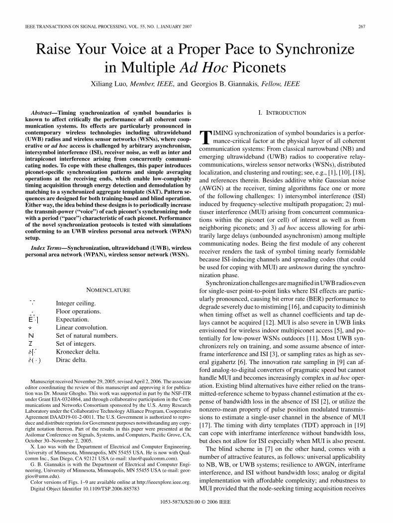
Fig. 2. Schematic illustrating the energy detector used in Theorem 1 for timingestimation.
B. Synchronization and Template Recovery
If the master node broadcasts the deterministic sync patternas in C3-T1), the waveform received by
any slave node can be written as [cf. (4)]
(5)
Taking expectation on both sides of (5), we find E. If we now consider any E
segment of size , the replica that falls into it willbe circularly shifted by . On the other hand, consecutive
replicas in (5) are separated by more than , sinceunder C2); see also Fig. 2. This guard time
which has size at least seconds, allows one to resolve thecircular shift and thus recover .
Interestingly, we arrive (within a scale ) at the same expres-sion for E , if we take expectation on both sides of (4) andadopt the pattern C3-B1) for which E .This observation establishes that similar to [7] which relied onC3-B1), even with the training pattern in C3-T1), the unknowntiming offset can be recovered using a low-complexity en-ergy detector as
E (6)
With available, the SAT of the received symbol waveformcan also be found as E .In practice, we consistently estimate E by averaging succes-sive segments of of duration to form
(7)
Using in place of E , we can readily obtain estimates ofthe timing and the SAT waveform as follows (see also[7]).
Theorem 1: Under C0)–C4), the timing offset and the SATcan be consistently estimated in the presence of AGN, ISI,
and MUI, using
(8)
where the operation is used because in (7) isestimated over a period of size whereas the integration in
270 IEEE TRANSACTIONS ON SIGNAL PROCESSING, VOL. 55, NO. 1, JANUARY 2007
(8) needs its periodic extension. Under C3-B1), the SAT esti-mate in (8) must be normalized by .
As detailed in [7], can be computed either digitally or inanalog form, and the maximization in (8) has to be performedover a finite grid of equispaced candidate offsets. Any desirableresolution can be achieved but the density of the grid is typicallyconstrained in practice by the affordable complexity.
The unified approach offered by Theorem 1 for training-basedor blind synchronization and SAT recovery is surprisinglysimple if one takes into account its attractive features which arenot matched by any existing alternative: Universal applicabilityto NB, WB, or UWB regimes, in the presence of AGN, ISI,and MUI. Only readily available upper bounds on channelparameters are required, for low-complexity estimation basedon sample averaging and energy detection. Neither transmit–re-ceive filters nor channels or spreading codes need to be known,so long as they remain invariant while averaging is performedin (7). Furthermore, it is worth mentioning that the approachworks even when phase errors are present at the transmitter,pulse distortions in the propagation channel, and unmodeleddynamics at reception (all these can be lumped intowhich is allowed to be unknown).
The pros and cons of training-based versus blind alternativesare well known and the choice between the two depends on theapplication. As we alluded to at the beginning of this section,training acquires timing faster and more reliably but with theblind pattern one does not interrupt transmission and does notsacrifice rate. What is common to the training and blind patternsin C3-T1) and C3-B1) is that they both have the master-nodeincrease power (i.e., “raise its voice”) periodically to accomplishsynchronization. Fortunately, this increase is small since it iseffected in a few symbols and only during the synchronizationphase which is short relative to the data transmission phase.
C. SAT-Based Demodulation
Having and available, slave nodes can demodulateusing the output of an SAT-based correlator which captures fullmultipath energy and yields the detection statistic
(9)
Relying on , linear equalization or Viterbi’s algorithm canbe adopted for demodulation depending on the tradeoff betweenBER requirements and affordable implementation complexity.To further reduce complexity, one can absorb the ISI and MUIplus AWGN terms at the SAT correlator output into a singlecolored noise term and proceed with a low-complexity (albeitsuboptimal) slicer. In code division multiple access (CDMA)and UWB single or multiuser access with binary symbol trans-missions this amounts to demodulating symbols with the signdetector
sign (10)
For a single piconet, error performance of the timing esti-mator in (8) with the blind sync pattern and the SAT-baseddemodulator in (9) and (10) has been evaluated thoroughly in
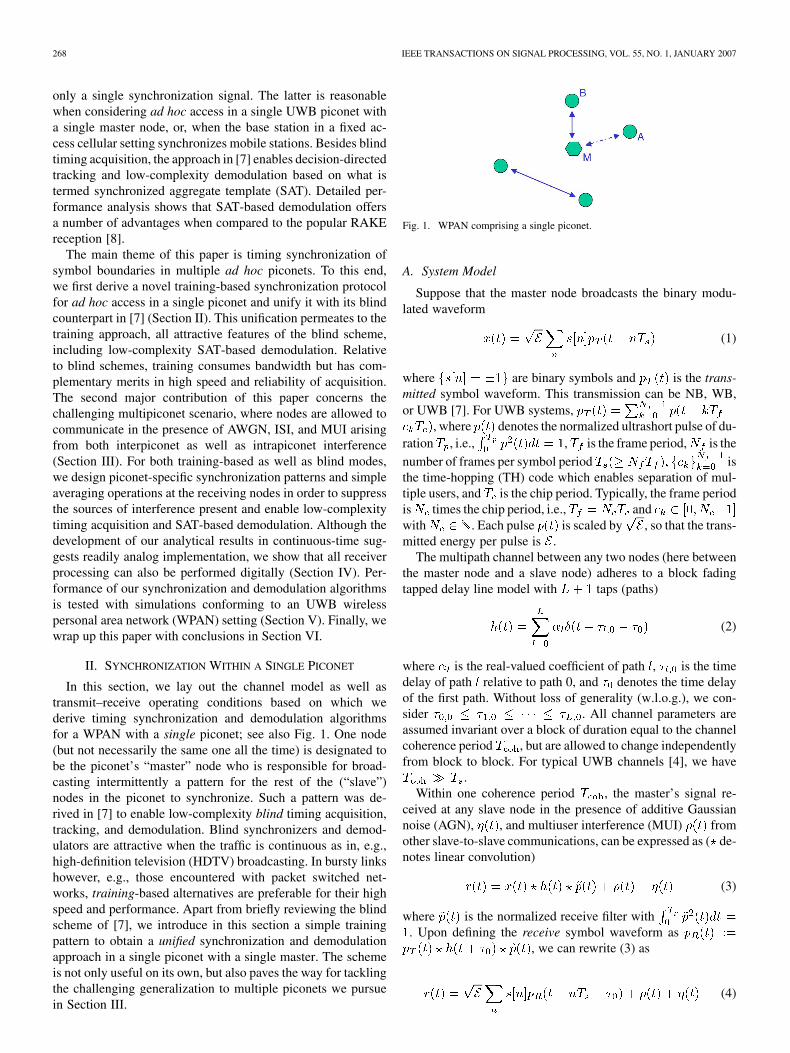
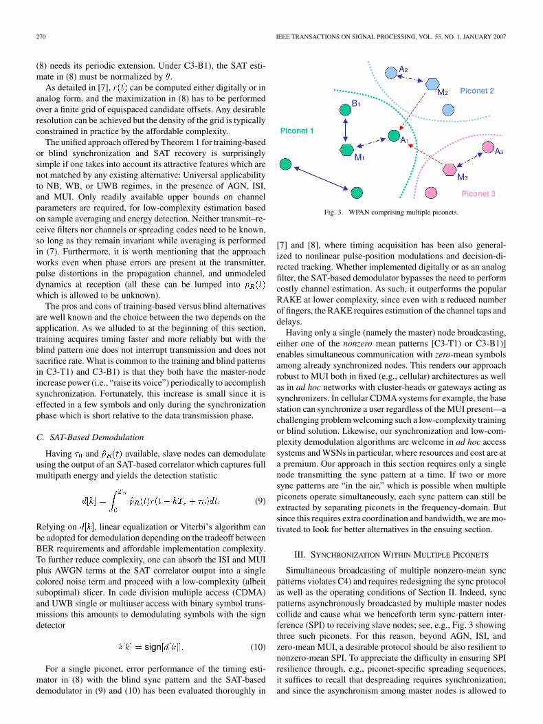
Fig. 3. WPAN comprising multiple piconets.
[7] and [8], where timing acquisition has been also general-ized to nonlinear pulse-position modulations and decision-di-rected tracking. Whether implemented digitally or as an analogfilter, the SAT-based demodulator bypasses the need to performcostly channel estimation. As such, it outperforms the popularRAKE at lower complexity, since even with a reduced numberof fingers, the RAKE requires estimation of the channel taps anddelays.
Having only a single (namely the master) node broadcasting,either one of the nonzero mean patterns [C3-T1) or C3-B1)]enables simultaneous communication with zero-mean symbolsamong already synchronized nodes. This renders our approachrobust to MUI both in fixed (e.g., cellular) architectures as wellas in ad hoc networks with cluster-heads or gateways acting assynchronizers. In cellular CDMA systems for example, the basestation can synchronize a user regardless of the MUI present—achallenging problem welcoming such a low-complexity trainingor blind solution. Likewise, our synchronization and low-com-plexity demodulation algorithms are welcome in ad hoc accesssystems and WSNs in particular, where resources and cost are ata premium. Our approach in this section requires only a singlenode transmitting the sync pattern at a time. If two or moresync patterns are “in the air,” which is possible when multiplepiconets operate simultaneously, each sync pattern can still beextracted by separating piconets in the frequency-domain. Butsince this requires extra coordination and bandwidth, we are mo-tivated to look for better alternatives in the ensuing section.
III. SYNCHRONIZATION WITHIN MULTIPLE PICONETS
Simultaneous broadcasting of multiple nonzero-mean syncpatterns violates C4) and requires redesigning the sync protocolas well as the operating conditions of Section II. Indeed, syncpatterns asynchronously broadcasted by multiple master nodescollide and cause what we henceforth term sync-pattern inter-ference (SPI) to receiving slave nodes; see, e.g., Fig. 3 showingthree such piconets. For this reason, beyond AGN, ISI, andzero-mean MUI, a desirable protocol should be also resilient tononzero-mean SPI. To appreciate the difficulty in ensuring SPIresilience through, e.g., piconet-specific spreading sequences,it suffices to recall that despreading requires synchronization;and since the asynchronism among master nodes is allowed to
LUO AND GIANNAKIS: RAISE YOUR VOICE AT PROPER PACE TO SYNCHRONIZE 271
be arbitrary, designing spreading codes which are (even approx-imately) orthogonal to all possible shifts is clearly impracticalbecause the required bandwidth is prohibitively large.
Instead of (de)spreading, our idea in this section is to de-sign training patterns with variable periods specific to each pi-conet- and corresponding receivers with averaging operationsspecific to each piconet- to suppress SPI and enable multipi-conet synchronization and SAT recovery. To this end, letdenote the number of piconets interfering the reception of aslave node under consideration. Supposing that all piconets
adopt the same symbol period , we can express thereceive waveform as
(11)
where is the waveform received at any slave node of pi-conet- as a result of the sync pattern transmitted by the masternode of piconet- ; denotes the MUI present at any nodeof piconet- which originates from slave nodes of the sameor other piconets; and is the AGN at the slave node ofpiconet- under consideration.1 Further, stands for thesymbol stream transmitted from the master node of piconet- ;
denotes the cor-responding waveform from piconet- received at any node ofpiconet- , where is the symbol waveform transmittedby the master of piconet- , and models the channel fromthe master node of piconet- to this receiving node of piconet-with time delay . We suppose that C0) and C2) of Section IIstill hold with proper modifications in notation, but we replaceC1) by the following.C1u) With an upper bound on the delay spread of all channels
involved known (and thus with the nonzero supportof also known ), we select theinteger .
As in Section II, C1u) will allow us to cope with ISI. To miti-gate SPI, we will need to modify also our sync patterns, startingwith the training-based ones, as follows.C3-Tu) The master node of the piconet- will transmit
, where [i.e., piconet-1will simply use C3-T1) as before]; but for , thesequence will be chosen periodic with period
satisfying three conditions. 1) Period is even. 2) If , then is even. 3) Sequence is binary valued with
for , and for.
Also, we can modify C4) as follows.C4u) Only the master node per piconet can transmit the nonzero
mean (NZM) sync pattern. As a result, and in(11) are zero mean, i.e., E E
.
1As a mnemonic, symbols with a single-piconet subscript pertain to transmitor receive quantities of the indicated piconet, while for symbols with two sub-scripts, the first subscript signifies the receiving piconet and the second one de-notes the piconet of the transmitting node.
Clearly, the constant sequence of piconet-1 canalso be viewed as periodic with period . Furthermore,we will see that selecting periodic with even period
, will allow us through proper averagingoperations over periods of size to eliminate SPI atreceiving slave nodes. This will be also facilitated by condition3) which dictates an equal number of s and s (hence,zero mean) per period, and also by condition 2) which basicallyasserts that the period of any piconet’s sync pattern shouldeither be an even multiple of another piconet’s smaller period,or it should yield another piconet’s larger period after beingmultiplied by an even number. Finally, our motivation behindbinary-valued samples is twofold: Constant modulus andsimplicity in averaging operations.
As an example of periods satisfying C3-Tu), consider the set
(12)
Notice though that there are more possibilities if one is willingto increase the periods assigned beyond , e.g., there is noneed to consider all the periods in the geometrically increasingset of (12), but select members with periods higher than .
Conditions 1)-3) under C3-Tu) endow the periodic withthree nice properties [P1)–P3)] that will prove handy in sup-pressing SPI; see the Appendixes A and B for their proofs. Thefirst one will be useful for slave nodes of piconet-1 to suppressSPI from piconets- .
P1) If is a multiple of and , then for any integershift , it holds for the sequences obeying C3-Tu) that
.The second property will enable slave nodes of each piconet
to recover the sync pattern of their master node.P2) For all integers and , with , it holds for
the sequences obeying C3-Tu) that.
The third property will allow slave nodes of a piconet-to suppress SPI originating from the master node of a piconet-with larger period training pattern.
P3) For , if with and, then , it holds for the se-
quences obeying C3-Tu) that.
Before proceeding, let us substitute the sync pattern of pi-conet- [cf. C3-Tu) with ] into (11) and use the Kroneckerdelta definition to obtain
(13)
Using P1)–P3) and this last expression of , we will shownext how the C3-Tu) sync patterns with proper operations atreceiving slave nodes can suppress SPI.
A. Suppression of SPI
To eliminate SPI in (11), each slave node of say piconet-should perform an operation enabling recovery of the signal
from its own master node and annihilation of the sig-nals from other masters . We have already seen
272 IEEE TRANSACTIONS ON SIGNAL PROCESSING, VOL. 55, NO. 1, JANUARY 2007
in Section II that sample averaging segments of size asin (7) allows recovery of piconet-1’s master-node pattern in theabsence of SPI. This will be used also here (after adding sub-scripts 1 for notational consistency) along with the followingreceive operations for piconets- with .C3-Ru) Slave nodes of piconet-1 will perform averaging as in
(7), i.e.,
(14)
Slave nodes of piconet- for all will perform
(15)
for . The number of segments averaged in(14) and (15) are selected to satisfy the following condi-tions: 1) must be a multiple of ; 2) mustbe even ; and 3) for andmust be an even multiple of .
As an example of the number of segments averaged by slavenodes, consider the set
(16)
for some . We can readily verify that with, e.g., theset of periods in (12), the set in (16) satisfies conditions 1)–3)under C3-Ru). Notice also that although the size of the periodsincreases with , the number of segments averaged decreaseswith . Hence, the overall time duration it takes to perform theaveraging operations in (14) and (15) is the same for all piconets,i.e., .
Having specified the training patterns broadcasted by themaster node of each piconet in C3-Tu) and the correspondingoperations performed by the receiving slave nodes of eachpiconet in C3-Ru), we are ready to show how their combinationenables SPI suppression. Starting with piconet-1, we alreadyknow from (5) that can recover the pattern of piconet-1,i.e., for
Proposition 1 shows that can also suppress SPI from allother piconets- with .
Proposition 1: Under C0), C1u), C2), C3-Tu), and C3-Ru),slave nodes of piconet-1 can annihilate SPI from piconet- ,
, i.e.,
Proof: Using (13) with and , we can write
where for the second equality, we used the change of variables, and in obtaining the last equality we relied on prop-
erty P1). [Recall also that P1) requires to be a multiple of ,thus justifying the need for condition 1) under C3-Ru)].
Switching roles, we also need to prove that a slave user inpiconet- , can recover the pattern of its own master nodewhile eliminating SPI from the master node of piconet-1.
Proposition 2: Under C0), C1u), C2), C3-Tu), and C3-Ru),slave nodes of piconet- can annihilate SPI from piconet-1while being able to recover the training signal from their ownmaster node of piconet- , i.e., for ,we have
Proof: To suppress interference from piconet-1, setin (8) and (13) to deduce that
. Upon plugging the latter into the averagingoperation performed by slave nodes of piconet- with ,we find that for
LUO AND GIANNAKIS: RAISE YOUR VOICE AT PROPER PACE TO SYNCHRONIZE 273
where the last equality follows because the last term in squarebrackets is zero for even, thus justifying the need for condi-tion 2) under C3-Ru).
To prove recovery of the training signal from the master nodeof piconet- , we use (8) and (13) with and plug theresultant into the averaging operation to obtain
for , where the last equality follows from prop-erty P2).
To this point, we have shown through Propositions 1 and 2how slave nodes of any piconet can recover the training signalof their own master node. We have also proved that interfer-ence to and from piconet-1 can be suppressed under C3-Tu) andC3-Ru). What is left to establish is SPI suppression to and frompiconet- for any . This is accomplished in Proposition 3.
Proposition 3: Under C0), C1u), C2), C3-Tu), and C3-Ru),slave nodes of piconet- can annihilate SPI from piconet- andvice versa, i.e., for and
Proof: Recalling condition 3) under C3-Tu) and supposingw.l.o.g. that , we can use to rewrite
as
which after invoking (13), with the roles of and inter-changed, yields
where the last equality follows since is even as per condition2) under C3-Ru). This shows that piconet- can cancel SPI frompiconet- .
To establish the converse, we plug (13) into the averagingoperation to arrive at
which upon changing variable to , yields
Recall now that is periodic with period , anduse condition 3) under C3-Ru) to write
for some . Using this into the last sum of theprevious equation, we deduce from property P3) that
which completes the proof of the proposition.
274 IEEE TRANSACTIONS ON SIGNAL PROCESSING, VOL. 55, NO. 1, JANUARY 2007
B. Timing and SAT Recovery
In Section III-A, we saw that with properly designed trainingpatterns as in C3-Tu) and with operations at receiving nodesadhering to C3-Ru), it is possible to extract the master node’ssignal in the piconet of interest from the SPI originating fromother piconets. In this section, we will use this extracted signalwaveform to acquire timing and recover the SAT of interest inthe multipiconet setup under consideration.
Since SPI has been suppressed, we can argue as in Theorem1 to recognize that AGN and MUI are also eliminated asymp-totically by the averaging operations C3-Ru) [cf. C4u)]. [Re-call that removal of ISI is already guaranteed thanks to C1u).]Specifically, as the averaging size grows large, in (14)converges to [cf. (11)], which according to Proposition 1is SPI-free, i.e., .Likewise, as we have for any piconet- that [cf. (11)and Propositions 2 and 3], as
(17)
Based on (17) and mimicking the steps from [7] we used forTheorem 1, we can readily prove the following.
Theorem 2: Under C0), C1u), C2), C3-Tu), C3-Ru), andC4u), the timing offset and the SAT of each pi-conet can be consistently estimated in the presenceof AGN, ISI, MUI, and SPI using
(18)
(19)
Because over the interval , the waveformin (17) actually contains independent shifted replicas of
, it is possible to improve the accuracy of the recoveredSAT using instead of (19) the weighted average estimator: For
(20)where the weights sign
account for possible sign differences among differentSAT replicas and is the SAT estimate from (19).
As in Section II-C, having and available, slavenodes in piconet- can demodulate information symbols usingthe detection statistic [cf. (9)]
(21)
which for binary symbols allows for simple demodulation usingthe sign detector
sign (22)
Since can take either or values, whenis outside the interval , although the esti-
mator in (18) produces a consistent timing estimate, therecovered SAT in (19) or (20) entails a possible sign am-biguity. For example, whenwith , we will have
, which will yield the correcttiming offset as .But even with the correct timing , the recovered SAT will be
,which has its sign reversed relative to the true SAT. For this pos-sible sign ambiguity in the estimated SAT of piconet- ,the detected symbols may have a systematic sign error.This ambiguity can certainly be handled using differential PSKmodulation ([13, Ch. 5]). Alternatively, we can extend thetransmit pattern in order to cope with this sign ambiguity. Onesimple approach is to append “ ” symbolsafter the training pattern. With the available SAT estimate
, we can then use the sign detector in (22) to find, and subsequently remove the sign ambiguity by
forming the SAT estimate (suppose is odd)
sign
(23)
In the sequel, we will ignore possible sign ambiguities since, ifpresent, they can be resolved using (23).
C. Blind Synchronization
Using the analogy between a deterministic periodic sequenceand the periodic mean of a cyclostationary received waveform,Theorem 1 unifies training-based and blind sync patterns forthe single-piconet scenario. Using the same analogy, it is evi-dent that our results in Sections III-A and III-B, which reliedon the training-based patterns for multipiconet synchronizationand SAT recovery, have their counterparts based on blind syncpatterns. For blind operation, however, C3-Tu) must be replacedby the following.C3-Bu) The master node of the piconet indexed by will
transmit
E (24)
where piconet-1 will use C3-B1) corresponding to, and the deterministic periodic sequence
as well as its period must obey conditions 1)–3)identical to those in C3-Tu).
If master nodes broadcast with the sync patterns C3-Bu), thenPropositions 1–3 remain valid for sufficiently large and SPIcan be suppressed. Formally stated, the law of large numbersimplies that for any , when
(25)
However, the latter implies that the timing and SAT estimatorsof Theorem 2 as well as the weighted and sign-compensated
LUO AND GIANNAKIS: RAISE YOUR VOICE AT PROPER PACE TO SYNCHRONIZE 275
SAT estimators of (20) and (23) can remain operational also ina blind mode. This is quite remarkable because AGN, ISI, MUI,and SPI can be handled without interrupting the broadcast andwithout bandwidth loss. As our simulations will confirm, at theexpense of requiring larger sample sizes for longer averaging,blind estimators can approach the performance of their training-based counterparts.
We will close this section with two remarks.Remark 1: In this section, we dealt with multiple piconets
each with a single master-node broadcasting the sync pattern.However, our results carry over to the uplink operation of a cel-lular, e.g., CDMA system where multiple (say ) ad hoc userswant to synchronize with a single access point. Viewing theseusers as the master nodes herein and equipping them with eitherthe C3-Tu) or the C3-Bu) patterns, solves the long-standingproblem of synchronizing multiple arbitrarily asynchronoususers in the presence of ISI and MUI. Notice that because thenumber of users seeking synchronization concurrently istypically small (as many as the number of neighboring mastersin the multipiconet setup), using in (12) requiresperiods of reasonable size.
Remark 2: Averaging continuous-time analog waveformsavoids the possibly high sampling rates involved in the UWBregime, but implementing analog delays required to shift suc-cessive segments by multiples [see (14) and (15)]can be challenging. Nonetheless, chips implementing analogdelays from 20 to 1000 ns are available [15] but they are costlyand have low accuracy and tolerances. On the other hand, whensampling at 1–2 GHz can be afforded, it is possible to store andprocess digitally, which also facilitates the maximizationrequired to find in (18). In Section IV, we elaboratefurther on this digital approach.
IV. DIGITAL IMPLEMENTATION
Although all previous derivations were carried out in contin-uous time, all estimators we developed can also be implementeddigitally. Indeed, upon sampling in (11) every seconds,we obtain
(26)
where for notational simplicity we have assumed thatwith , and with .
Over the time interval , we can collect thesamples of in a vector
. Based on , the receiver ofany slave node in piconet-1 will form the average
(27)
Likewise, the receiver of any slave node in piconet-, will form
(28)
We can then select as, e.g., in (12) and as, e.g., in (16) inorder to suppress SPI and recover the signal from the piconet ofinterest using either C3-Bu) or C3-Tu) patterns as establishedby Propositions 1–3. Then, we can estimate the digital timing
using
(29)where and we have used Matlab’s notation
to denote the subvector formed by the throughentries of a vector . With timing acquired, we can recover
, corresponding to theSAT of piconet- , as
(30)
After timing acquisition and SAT recovery, we can form sim-ilar to (21) the decision statistic
based on which we can proceed with a slicer or more elaboratedemodulation schemes such as zero-forcing, minimum mean-square error or maximum-likelihood multiuser detectors.
Remark 3: As far as the sampling rate is concerned,we can either use Nyquist or sub-Nyquist sampling which cor-responds to approximating the integral in the detection statistic[cf. (21)] with a large step size to form . Another op-tion is to filter the received waveform before sampling so thatNyquist rate is affordable. For example, we can have a frond-end500 MHz bandpass filter and sample its output at 1-GHz rate.Certainly, demodulation performance in this case is traded offfor relaxed sampling requirements.
Remark 4: Because the channel is changing with time,our averaging time should be limited to a small fraction ofthe channel coherent time. As discussed in [4], the antici-pated speed of moving users in a typical UWB scenario isabout 1 m/s, which implies that the rate of channelvariation is upper bounded by 3 ns/s. With maximum car-rier frequency 6 GHz, the maximum Doppler spread is:
20 Hz. The channelcoherence time is then about [14, Ch. 4]:21 ms. For the UWB system that we will simulate in Section V,the symbol period is 330 ns. We will have about
64 000 symbols within one coherence period. Aswe will see in the ensuing section, only a small fraction of thiscoherence period suffices for our multipiconet synchronizationand demodulation algorithms.
276 IEEE TRANSACTIONS ON SIGNAL PROCESSING, VOL. 55, NO. 1, JANUARY 2007
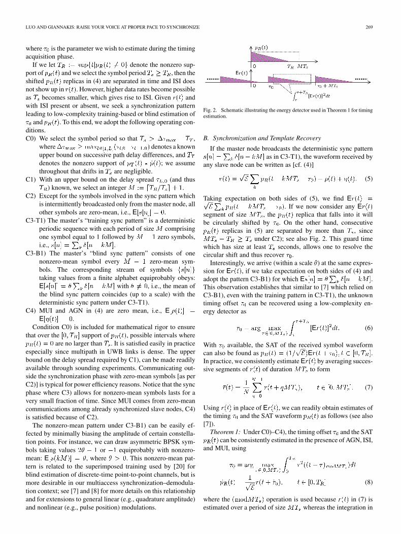
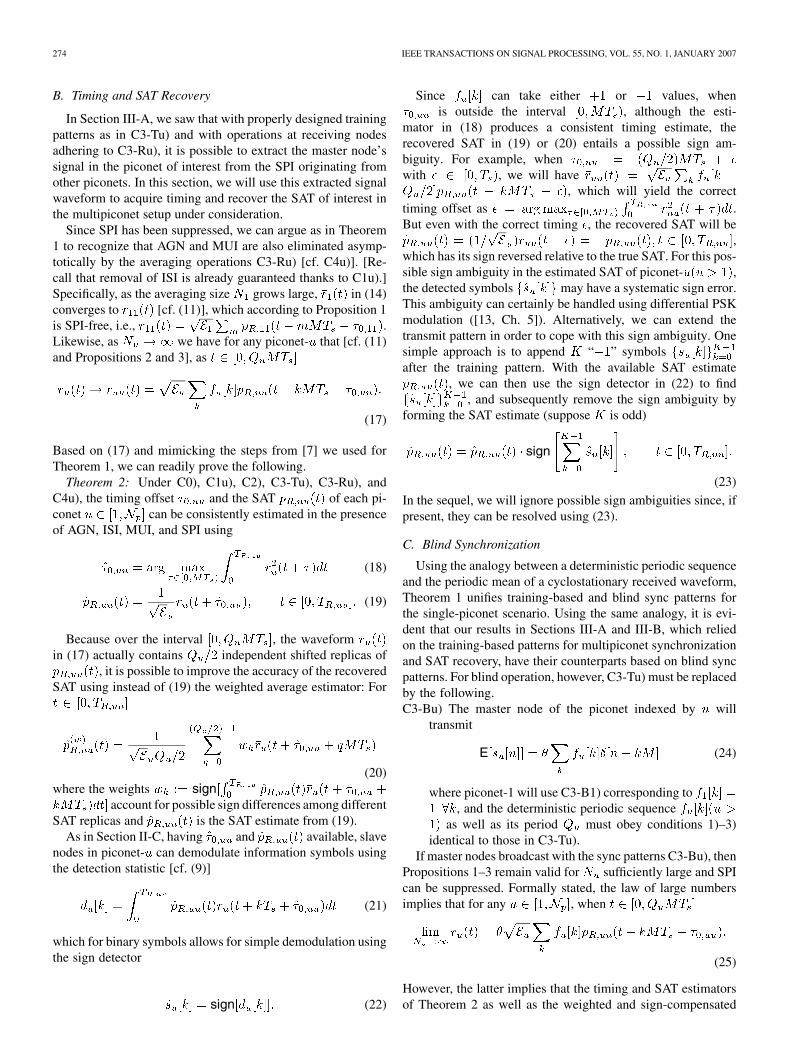
Fig. 4. SPI-resilient training patterns (M = 2) as in C3-Tu).
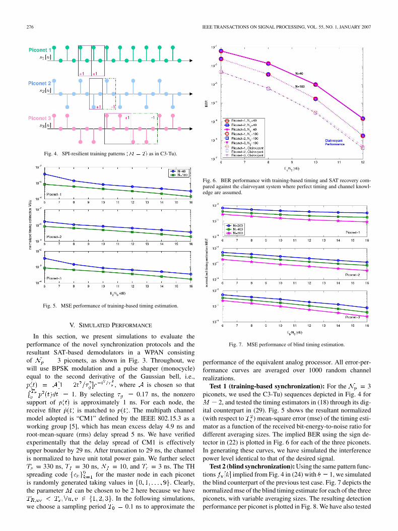
Fig. 5. MSE performance of training-based timing estimation.
V. SIMULATED PERFORMANCE
In this section, we present simulations to evaluate theperformance of the novel synchronization protocols and theresultant SAT-based demodulators in a WPAN consistingof 3 piconets, as shown in Fig. 3. Throughout, wewill use BPSK modulation and a pulse shaper (monocycle)equal to the second derivative of the Gaussian bell, i.e.,
, where is chosen so that
1. By selecting 0.17 ns, the nonzerosupport of is approximately 1 ns. For each node, thereceive filter is matched to . The multipath channelmodel adopted is “CM1” defined by the IEEE 802.15.3 as aworking group [5], which has mean excess delay 4.9 ns androot-mean-square (rms) delay spread 5 ns. We have verifiedexperimentally that the delay spread of CM1 is effectivelyupper bounder by 29 ns. After truncation to 29 ns, the channelis normalized to have unit total power gain. We further select
330 ns, 30 ns, 10, and 3 ns. The THspreading code for the master node in each piconetis randomly generated taking values in . Clearly,the parameter can be chosen to be 2 here because we have
. In the following simulations,we choose a sampling period 0.1 ns to approximate the
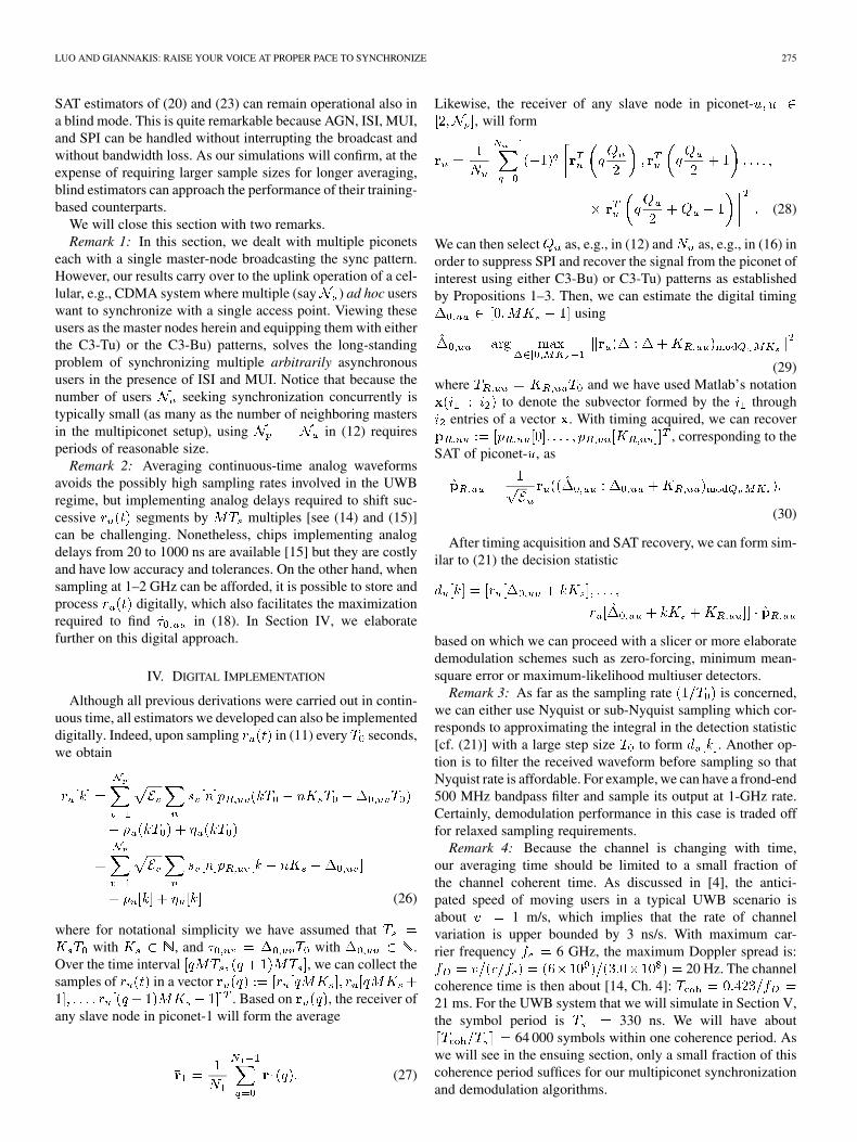
Fig. 6. BER performance with training-based timing and SAT recovery com-pared against the clairvoyant system where perfect timing and channel knowl-edge are assumed.
Fig. 7. MSE performance of blind timing estimation.
performance of the equivalent analog processor. All error-per-formance curves are averaged over 1000 random channelrealizations.
Test 1 (training-based synchronization): For the 3piconets, we used the C3-Tu) sequences depicted in Fig. 4 for
2, and tested the timing estimators in (18) through its dig-ital counterpart in (29). Fig. 5 shows the resultant normalized(with respect to ) mean-square error (mse) of the timing esti-mator as a function of the received bit-energy-to-noise ratio fordifferent averaging sizes. The implied BER using the sign de-tector in (22) is plotted in Fig. 6 for each of the three piconets.In generating these curves, we have simulated the interferencepower level identical to that of the desired signal.
Test 2 (blind synchronization): Using the same pattern func-tions implied from Fig. 4 in (24) with 1, we simulatedthe blind counterpart of the previous test case. Fig. 7 depicts thenormalized mse of the blind timing estimate for each of the threepiconets, with variable averaging sizes. The resulting detectionperformance per piconet is plotted in Fig. 8. We have also tested
LUO AND GIANNAKIS: RAISE YOUR VOICE AT PROPER PACE TO SYNCHRONIZE 277
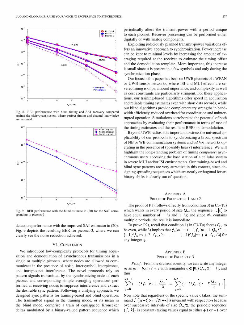
Fig. 8. BER performance with blind timing and SAT recovery comparedagainst the clairvoyant system where perfect timing and channel knowledgeare assumed.
Fig. 9. BER performance with the blind estimate in (20) for the SAT corre-sponding to piconet-3.
detection performance with the improved SAT estimator in (20).Fig. 9 depicts the resulting BER for piconet-3, where we canclearly see the noise reduction achieved.
VI. CONCLUSION
We introduced low-complexity protocols for timing acqui-sition and demodulation of asynchronous transmissions in asingle or multiple piconets, where nodes are allowed to com-municate in the presence of noise, intersymbol, interpiconet,and intrapiconet interference. The novel protocols rely onpattern signals transmitted by the synchronizing node of eachpiconet and corresponding simple averaging operations per-formed at receiving nodes to suppress interference and extractthe desirable sync pattern. Following a unifying approach, wedesigned sync patterns for training-based and blind operation.The transmitted signal in the training mode, or its mean inthe blind mode, comprise a train of equispaced Kroneckerdeltas modulated by a binary-valued pattern sequence which
periodically alters the transmit-power with a period uniqueto each piconet. Receiver processing can be performed eitherdigitally or with analog components.
Exploiting judiciously planned transmit-power variations of-fers an innovative approach to synchronization. Power increasecan be kept to minimal levels by increasing the amount of av-eraging required at the receiver to estimate the timing offsetand the demodulation template. More important, this increaseis small since it is present in a few symbols and only during thesynchronization phase.
Our focus in this paper has been on UWB piconets of a WPANor UWB sensor networks, where ISI and MUI effects are se-vere, timing is of paramount importance, and complexity as wellas cost constraints are particularly stringent. For these applica-tions, our training-based algorithms offer speed in acquisitionand reliable timing estimates even with short data records, whileour blind algorithms provide complementary strengths in band-width efficiency, reduced overhead for coordination and uninter-rupted operation. Simulations corroborated the potential of bothapproaches by evaluating their performance in terms of mse ofthe timing estimates and the resultant BERs in demodulation.
Beyond UWB radios, it is important to stress the universal ap-plicability of our protocols to synchronizing a broad spectrumof NB or WB communication systems and ad hoc networks op-erating in the presence of (possibly heavy) interference. We willhighlight the long-standing problem of timing completely asyn-chronous users accessing the base station of a cellular systemin severe MUI and/or ISI environments. Our training-based andblind sync patterns are very attractive in this context, since de-signing spreading sequences which are nearly orthogonal for ar-bitrary shifts is clearly out of question.
APPENDIX APROOF OF PROPERTIES 1 AND 2
The proof of P1) follows directly from condition 3) in C3-Tu)which wants in every period of size , the sequence tohave equal number of ’s and ’s; and since containsmultiple periods, the result is immediate.
To prove P2), recall that condition 1) in C3-Tu) forces tobe even, while 3) implies that
forany integer .
APPENDIX BPROOF OF PROPERTY 3
Proof: From the division identity, we can write any integeras with remainder , and
thus
Now note that regardless of the specific value takes, the sum-mand is invariant with respect to becauseover successive intervals of size , the periodic sequence
is constant (taking values equal to either or over
278 IEEE TRANSACTIONS ON SIGNAL PROCESSING, VOL. 55, NO. 1, JANUARY 2007
such intervals) [cf. condition 3) in C3-Tu)]. For this reason, wecan set w.l.o.g. and seek a proof of
(31)
We will prove (31) by induction on integer . Since, we have for that
when , and when. Hence, (31) is satisfied for , since
.Supposing that (31) holds for some , i.e.,
, we want to show that (31)is true for , i.e., we wish to show that the sum
is zero (the equality follows after changing variables to). However, after splitting the last sum, we readily see that
(32)
where we have used the induction assumption to zerothe first term, and the fact that is periodic withperiod , which implies that
and nulls the dif-ference between the last two terms. This completes theinduction and the proof of P3).
REFERENCES
[1] J. C. Chen, K. Yao, and R. E. Hudson, “Source localization and beam-forming,” IEEE Signal Process. Mag., vol. 19, no. 2, pp. 30–39, Mar.2002.
[2] R. Djapic, G. Leus, and A.-J. van der Veen, “Blind synchronizationin asynchronous UWB networks based on the transmit-referencescheme,” in Proc. Asilomar Conf. Signals, Syst., Comput., PacificGrove, CA, Nov. 2004, pp. 1506–1510.
[3] E. A. Homier and R. A. Scholtz, “Rapid acquisition of ultra-widebandsignals in the dense multi-path channels,” in Proc. Conf. Ultra-Wide-band Syst. Technol., Baltimore, MD, May 20–23, 2002, pp. 105–110.
[4] IEEE P802.15 Working Group for WPANs, “Time variance for UWBwireless channels” IEEE P802.15-02/461r1-SG3a, Nov. 2002.
[5] IEEE P802.15 Working Group for WPANs, “Channel modeling sub-committee report final” IEEE P802.15-02/368r5-SG3a, Nov. 2002.
[6] V. Lottici, A. D. Andrea, and U. Mengali, “Channel estimation forultra-wideband communications,” IEEE J. Sel. Areas Commun., vol.20, no. 9, pp. 1638–1645, Dec. 2002.
[7] X. Luo and G. B. Giannakis, “Low-complexity blind synchronizationand demodulation for (ultra-) wideband multi-user ad hoc access,”IEEE Trans. Wireless Commun., vol. 5, no. 7, pp. 1930–1941, Jul.2006.
[8] X. Luo and G. B. Giannakis, “Cyclic-mean based synchronization andefficient demodulation for UWB ad hoc access: Generalizations andcomparisons,” EURASIP J. Signal Process., vol. 89, pp. 2139–2152,Sep. 2006.
[9] I. Maravic, J. Kusuma, and M. Vetterli, “Low-sampling UWB channelcharacterization and synchronization,” J. Commun. Netw., vol. 5, no.4, pp. 319–327, Dec. 2003.
[10] U. Mengali and A. D. Andrea, Synchronization Techniques for DigitalReceivers. New York: Plenum, 1997.
[11] I. Oppermann, L. Stoica, A. Rabbachin, Z. Shelby, and J. Haapola,“UWB wireless sensor networks: UWEN—A practical example,”IEEE Commun. Mag., vol. 42, no. 12, pp. S27–S32, Dec. 2004.
[12] D. Porrat and D. Tse, “Bandwidth scaling in ultra wideband communi-cation,” presented at the 41st Allerton Conf., Monticello, IL, Oct. 1–3,2003.
[13] J. G. Proakis, Digital Communications, 4th ed. New York: McGraw-Hill, 2000.
[14] T. S. Rappaport, Wireless Communications—Principles and Practice,2nd ed. Englewood Cliffs, NJ: Prentice-Hall, 2001.
[15] RCD Components Inc. [Online]. Available: http://216.153.156.169:8080/rcd/rcdpdf/P1410-P2420.pdf
[16] Z. Tian and G. B. Giannakis, “BER sensitivity to mistiming in ultra-wideband communications,” IEEE Trans. Signal Process., vol. 53, no.4, pp. 1550–1560, Apr. 2005.
[17] Z. Wang and X. Yang, “Blind channel estimation for ultra wide-bandcommunications employing pulse position modulation,” IEEE SignalProcess. Lett., vol. 12, no. 7, pp. 520–523, Jul. 2005.
[18] L. Yang and G. B. Giannakis, “Ultra-wideband communications: Anidea whose time has come,” IEEE Signal Process. Mag., vol. 21, no. 6,pp. 26–54, Nov. 2004.
[19] L. Yang and G. B. Giannakis, “Timing UWB signals using dirty tem-plates,” IEEE Trans. Commun., vol. 53, no. 11, pp. 1952–1963, Nov.2005.
[20] G. T. Zhou, M. Viberg, and T. McKelvey, “A first-order statisticalmethod for channel estimation,” IEEE Signal Process. Lett., vol. 10,no. 2, pp. 57–60, Mar. 2003.
Xiliang Luo (S’03–M’06) received the B.S. degreein physics from Peking University, Beijing, China,in 2001 and the M.S. and Ph.D. degrees in electricalengineering from the University of Minnesota, Min-neapolis, in 2003 and 2006, respectively.
In 2006, he joined Qualcomm Inc., San Diego, CA,where he is currently working on the long-term evolu-tion of 3G. His general research interests lie in signalprocessing, communication, and information theory.
Georgios B. Giannakis (S’84–M’86–SM’91–F’97)received the Diploma in electrical engineering fromthe National Technical University of Athens, Athens,Greece, in 1981 and the M.Sc. degree in electricalengineering, M.Sc. degree in mathematics, and Ph.D.degree in electrical engineering from the Universityof Southern California (USC), Los Angeles, in 1983,1986, and 1986, respectively.
After lecturing for one year at USC, he joined theUniversity of Virginia in 1987, where he became aProfessor of Electrical Engineering in 1997. Since
1999, he has been a Professor with the Department of Electrical and Com-puter Engineering, University of Minnesota, Minneapolis, where he now holdsan ADC Chair in Wireless Telecommunications. His general interests are in theareas of communications and signal processing, estimation and detection theory,time-series analysis, and system identification—subjects on which he has au-thored or coauthored more than 200 journal papers, 350 conference papers, andtwo edited books. His current research focuses on transmitter and receiver diver-sity techniques for single and multiuser fading communication channels, com-plex-field and space–time coding, multicarrier, ultrawideband wireless commu-nication systems, cross-layer designs, and sensor networks.
Dr. Giannakis is the corecipient of six paper awards from the IEEE SignalProcessing (SP) and Communications Societies (1992, 1998, 2000, 2001,2003, 2004). He also received the IEEE SP Society’s Technical Achieve-ment Award in 2000. He served as an Editor-in-Chief for the IEEE SIGNAL
PROCESSING LETTERS, Associate Editor for the IEEE TRANSACTIONS ON
SIGNAL PROCESSING and the IEEE SIGNAL PROCESSING LETTERS, Secretaryof the SP Conference Board, member of the SP Publications Board, memberand Vice-Chair of the Statistical Signal and Array Processing TechnicalCommittee, Chair of the SP for Communications Technical Committee, andmember of the IEEE Fellows Election Committee. He has also served as amember of the IEEE-SP Society’s Board of Governors, the Editorial Boardfor the PROCEEDINGS OF THE IEEE, and the Steering Committee of the IEEETRANSACTIONS ON WIRELESS COMMUNICATIONS.