Embed Size (px)
Citation preview
IEEE TRANSACTIONS ON POWER ELECTRONICS, VOL. 21, NO. 2, MARCH 2006 459
Active Harmonic Eliminationfor Multilevel Converters
Zhong Du, Student Member, IEEE, Leon M. Tolbert, Senior Member, IEEE, andJohn N. Chiasson, Senior Member, IEEE
Abstract—This paper presents an active harmonic eliminationmethod to eliminate any number of specific higher order har-monics of multilevel converters with equal or unequal dc voltages.First, resultant theory is applied to transcendental equationscharacterizing the harmonic content to eliminate low order har-monics and to determine switching angles for the fundamentalfrequency switching scheme and a unipolar switching scheme.Next, the residual higher order harmonics are computed andsubtracted from the original voltage waveform to eliminate them.The simulation results show that the method can effectively elim-inate the specific harmonics, and a low total harmonic distortion(THD) near sine wave is produced. An experimental 11-levelH-bridge multilevel converter with a field programmable gatearray controller is employed to implement the method. The exper-imental results show that the method does effectively eliminate anynumber of specific harmonics, and the output voltage waveformhas low THD.
Index Terms—Active harmonic elimination, field programmablegate array (FPGA) controller, multilevel converter.
I. INTRODUCTION
MULTILEVEL converters have received more and moreattention because of their capability of high voltage
operation, high efficiency, and low electromagnetic interference(EMI) [1], [2]. The desired output of a multilevel converteris synthesized by several sources of dc voltages. With anincreasing number of dc voltage sources, the converter voltageoutput waveform approaches a nearly sinusoidal waveformwhile using a fundamental frequency switching scheme. Thisresults in low switching losses, and because of several dcsources, the switches experience a lower . As a result,multilevel converter technology is promising for high powerelectric devices such as utility applications [3]. For theseapplications, the output voltage of the converters must meetmaximum total harmonic distortion (THD) limitations such asthose specified in IEEE 519 [4]; therefore, some kind of methodmust be used to control the harmonics.
The traditional PWM method, space vector pulse-widthmodulation (PWM) method, sub-harmonic PWM method(SH-PWM) [5], and switching frequency optimal PWM
Manuscript received December 10, 2004; revised June 24, 2005. This workwas supported in part by the National Science Foundation under Contract NSFECS-0093884 and by the Oak Ridge National Laboratory under UT/BattelleContract 400023754. Recommended by Associate Editor J. H. R. Enslin.
L. M. Tolbert and J. N. Chiasson are with the Department of Electrical andComputer Engineering, The University of Tennessee, Knoxville, TN 37996-2100 USA (e-mail: [email protected]; [email protected]).
Z. Du is with the Department of Electrical and Computer Engineering, NorthCarolina State University, Raleigh, NC 27695 USA (e-mail: [email protected]).
Digital Object Identifier 10.1109/TPEL.2005.869757
(SFO-PWM) [6] for multilevel converters require equal dcvoltage sources. For fundamental switching scheme, the tran-scendental equations characterizing the harmonic content canbe converted into polynomial equations. Elimination theory[7]–[9] has been employed to determine the switching anglesto eliminate specific harmonics, such as the fifth, seventh, 11th,and the 13th. However, as the number of dc sources increases,the degrees of the polynomials in these equations are large andone reaches the limitations of contemporary computer algebrasoftware tools (e.g., Mathematica or Maple) to solve the systemof polynomial equations using resultants [11]. Another methodto eliminate harmonics in multilevel inverters is highlighted in[15].
The benefit of the fundamental frequency switching methodis its low switching frequency compared to other controlmethods. Generally, the computational complexity of the resul-tant method limits its use to multilevel converters with equaldc sources. If one wanted to apply the method to multilevelconverters with unequal dc sources, the set of transcendentalequations to be solved are no longer symmetric and requirethe solution of a set of high-degree equations, which is beyondthe capability of contemporary computer algebra [12]. In orderto use the method, the constant dc source voltages must bemaintained which increases the cost of the system [13].
Because of the computational difficulty of the resultantmethod for high degree polynomials, a new active harmonicelimination algorithm is proposed in this paper to eliminatehigher order harmonics. First, the low order harmonics (e.g.,the fifth, seventh, 11th, and 13th) can be eliminated using a fun-damental frequency switching scheme for the equal dc voltagesituation or by using a unipolar switching scheme for theunequal dc voltage situation in which the switching angles aredetermined using elimination theory. Next, specifically chosenhigher harmonics (the odd, nontriplen harmonics, such as the19th, 23rd, 25th, and 29th in the experiments) are eliminatedby using an additional switching angle (one for each higherharmonic) with corresponding higher frequency to generatethe opposite of the harmonic to cancel it. Therefore, the outputvoltage waveform will have low THD.
Here, an experimental 11-level H-bridge multilevel converterwith a field programmable gate array (FPGA) controller is em-ployed to implement the method. The experimental results showthat the method can effectively eliminate any number of specificharmonics for multilevel converters with equal dc voltages orunequal dc voltages, and the output voltage waveform has muchless THD than that from the fundamental switching scheme andthe unipolar switching scheme.
0885-8993/$20.00 © 2006 IEEE
460 IEEE TRANSACTIONS ON POWER ELECTRONICS, VOL. 21, NO. 2, MARCH 2006
Fig. 1. (a) Topology of single phase cascaded H-bridge multilevel converterand (b) output waveform of multilevel converter using fundamental frequencyswitching scheme.
The active harmonic elimination method also offers flexibilitywith the option of increasing the switching frequency for higherorder harmonic elimination. In order to eliminate more har-monics than the number of levels in a multilevel converter, theswitching frequency must be higher because generating the op-posite higher order harmonics needs more switchings in a cycle,however.
II. HARMONIC ELIMINATION FOR MULTILEVEL
CONVERTER WITH EQUAL dc VOLTAGES
A. Low Order Harmonic Elimination
A cascaded H-bridge multilevel converter uses several dcsources to synthesize a sinusoidal wave. Fig. 1(a) shows thetopology of a single-phase cascaded H-bridge multilevel con-verter. The control of the multilevel converter is to choose aseries of switching angles to synthesize a desired sinusoidalvoltage waveform. The 11-level multilevel converter outputvoltage waveform generated by the fundamental frequencyswitching scheme is shown in Fig. 1(b).
If the dc voltages for all the H-bridges are equal, which isdefined as here, the Fourier series expansion of the outputvoltage waveform using fundamental frequency switchingscheme as shown in Fig. 1 is
(1)
where is the number of dc sources in a cascaded H-bridge mul-tilevel converter. Ideally, given a desired fundamental voltage
, one wants to determine the switching angles sothat , and specific higher harmonics of
are equal to zero. For a three-phase applica-tion, the triplen harmonics in each phase need not be cancelledas they automatically cancel in the line-to-line voltages. For ex-ample, in the case of 5 dc sources, the fifth, seventh, 11th,and 13th order harmonics can be canceled.
The switching angles can be found by solving (2), shown atthe bottom of the page, where the modulation index is definedas .
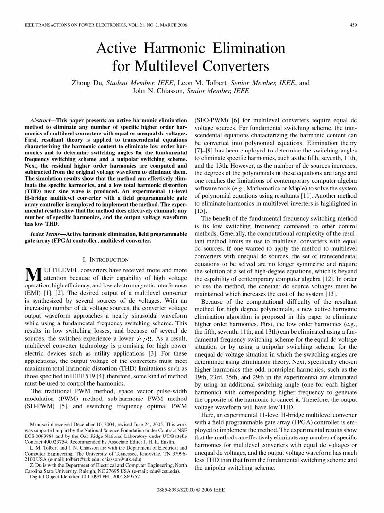
These transcendental equations characterizing the harmoniccontent can be converted into polynomial equations, and the re-sultant method is employed to find all their solutions when theyexist [7], [8]. The 11-level solutions are shown in Fig. 2(a). Thehigher order harmonic voltages are computed by (1), and theTHD for the corresponding solution is computed according to
is shown in Fig. 2(b).From the solution set shown in Fig. 2(a), the solutions exist
only for in a range from 1.88 to 4.23. Futhermore, even in thisrange there are intervals of for which no solution exists. Also,some modulation indices have more than one set of solutionswith different values for their residual harmonics and thus THD.For practical applications, the set of switching angles with thelowest THD will be used for implementation.
B. High Order Harmonic Elimination
From (1), the voltage content can be divided into four parts
(3)
1) Fundamental frequency voltage:
(4)
2) Triplen harmonic voltages:
(5)
3) Low order harmonic voltages that can be eliminated byapplying the resultant method:
(6)
(2)
DU et al.: ACTIVE HARMONIC ELIMINATION FOR MULTILEVEL CONVERTERS 461
Fig. 2. (a) Solutions for switching angles versusm and (b) corresponding THD versusm.
4) High order harmonic voltages that are not eliminated byapplying the resultant method:
(7)
Using the resultant method of [10], [11], is set, andgiven in (6) is identically zero by choosing the switching
angles appropriately. Assuming the application is a balancedthree-phase system, in (5) need not be eliminated becausethese harmonics cancel in the line-line voltage. This then leaves
in (7). To eliminate these harmonics, a square wave is gen-erated (one for each of these harmonics) whose fundamentalis the opposite of the harmonic that is to be eliminated. Forexample, to eliminate the 17th harmonic (let 17), a squarewave whose Fourier series expansion is
(8)
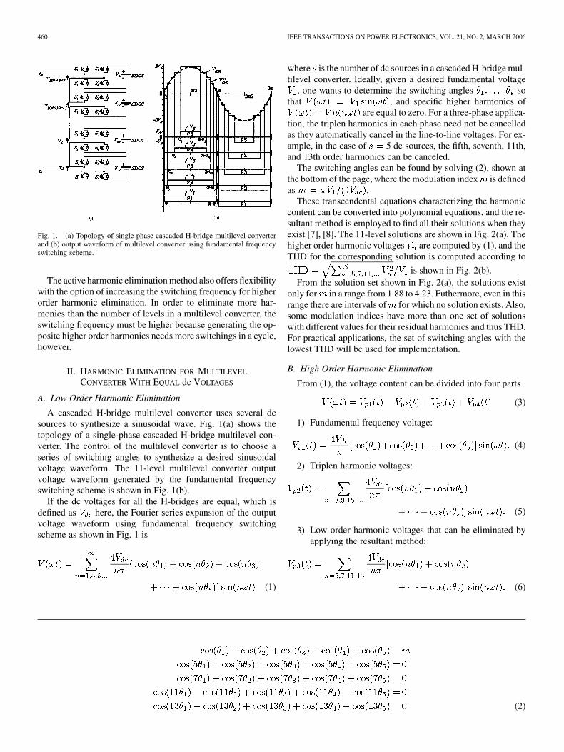
is generated. The 1, 17 term of (8) cancels the17 term of (7) and the next harmonic of concern that is pro-duced by (8) is at 5 17 85. This harmonic and higher ones(7 17, etc.,) are easy to filter using a low-pass filter. Repeatingthe above procedure, the 19th, 23rd, , 49th harmonics can allbe eliminated. The net effect of this method is to remove the loworder harmonics at the expense of generating new higher orderharmonics and increasing the switching frequency. This methodis referred to as active harmonic elimination method because theharmonic elimination is realized in the converter, not by a pas-sive filter. The THD of the output voltage that eliminates all ofthe low order harmonics up to 31st versusis shown in Fig. 3. Compared to the fundamental frequencyswitching method, the THD is much lower.
Fig. 3. THDs for active harmonic elimination method to eliminate harmonicsup to 31st and for fundamental frequency switching method.
Fundamental frequency switchings to eliminate harmonicsincurs only five switching per cycle to control the fundamentaland eliminate the fifth, seventh, 11th, and 13th harmonics. Toeliminate the th harmonic (when more harmonics are desiredto be eliminated than there are levels in the converter), the mul-tilevel converter active devices are required to switch an extra
times in a cycle. The additional number of switchings in acycle for the active harmonic elimination method is
17,19,23,25,29,31 , where is the harmonic number.
If a harmonic is near zero and the time step resolution is lowerthan that required to eliminate the harmonic, then switchingwill not occur. In this work, no attempt was made to eliminateresidual harmonics with amplitudes less than 0.5% of the fun-damental.
462 IEEE TRANSACTIONS ON POWER ELECTRONICS, VOL. 21, NO. 2, MARCH 2006
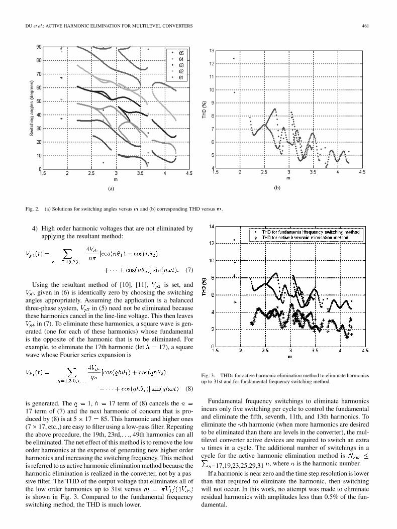
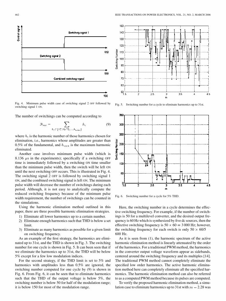
Fig. 4. Minimum pulse width case of switching signal 2 OFF followed byswitching signal 1 ON.
The number of switchings can be computed according to
(9)
where is the harmonic number of those harmonics chosen forelimination, i.e., harmonics whose amplitudes are greater than0.5% of the fundamental, and is the maximum harmoniceliminated.
Another case involves minimum pulse width (which is8.136 s in the experiments); specifically if a switching OFF
time is immediately followed by a switching ON time smallerthan the minimum pulse width, then the switch will be left ON
until the next switching OFF occurs. This is illustrated in Fig. 4.The switching signal 2 OFF is followed by switching signal 1ON, and the combined switching signal is left ON. The minimumpulse width will decrease the number of switchings during eachperiod. Although, it is not easy to analytically compute thereduced switching frequency because of the minimum pulsewidth requirement, the number of switchings can be counted inthe simulations.
Using the harmonic elimination method outlined in thispaper, there are three possible harmonic elimination strategies.
1) Eliminate all lower harmonics up to a certain number.2) Eliminate enough harmonics such that THD is below a set
limit.3) Eliminate as many harmonics as possible for a given limit
on switching frequency.As an example of the first strategy, the harmonics are elimi-
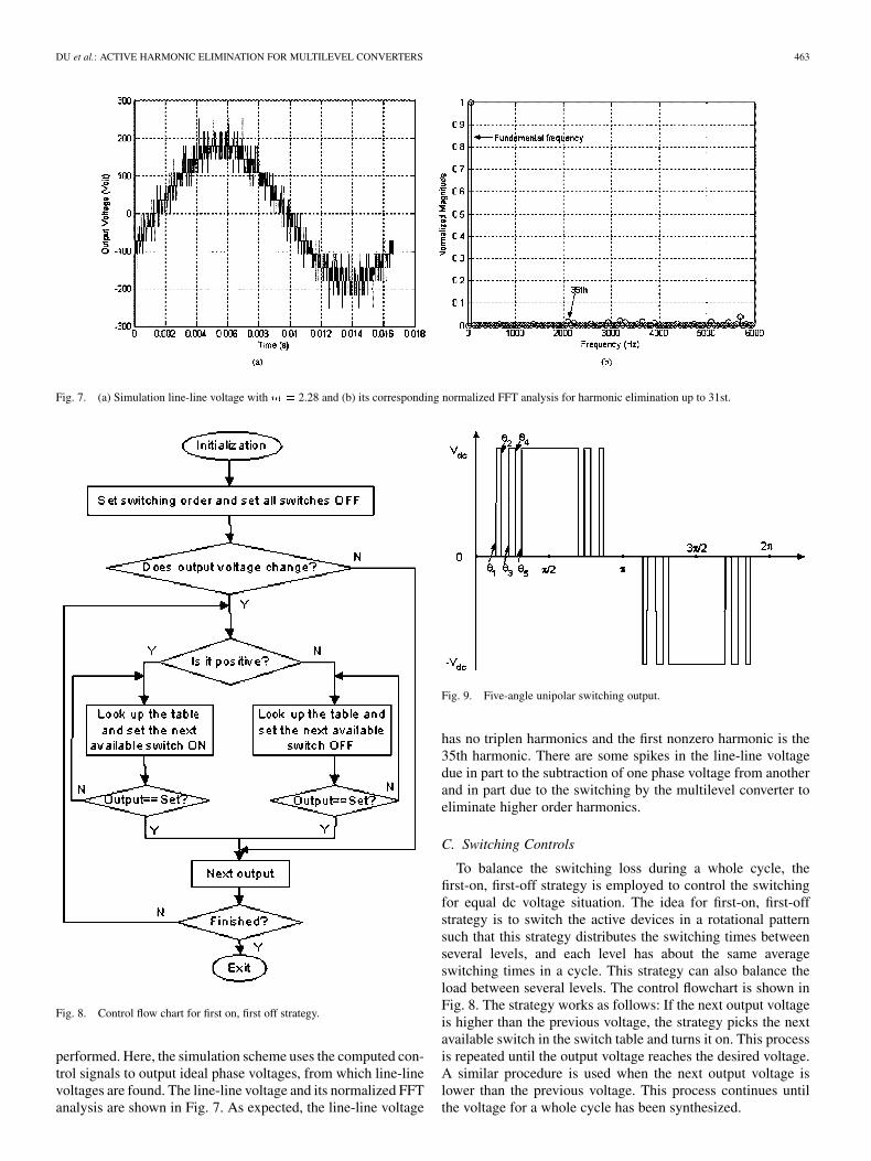
nated up to 31st, and the THD is shown in Fig. 3. The switchingnumber for one cycle is shown in Fig. 5. It can been seen that ifwe eliminate the harmonics up to 31st, the THD will be below5% except for a few low modulation indices.
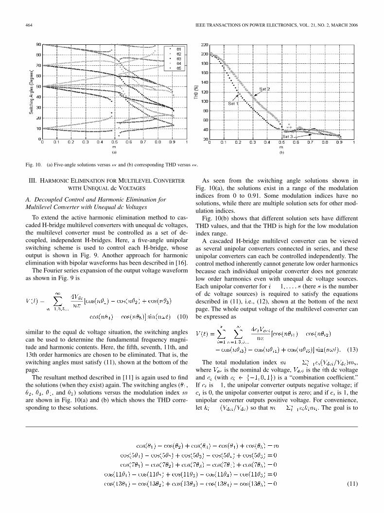
For the second strategy, if the THD limit is set to 5% andharmonics with amplitudes less than 0.5% are ignored, theswitching number computed for one cycle by (9) is shown inFig. 6. From Fig. 6, it can be seen that to eliminate harmonicssuch that the THD of the output voltage is below 5%, theswitching number is below 50 for half of the modulation range;it is below 150 for most of the modulation range.
Fig. 5. Switching number for a cycle to eliminate harmonics up to 31st.
Fig. 6. Switching number for a cycle for 5% THD.
Here, the switching number in a cycle determines the effec-tive switching frequency. For example, if the number of switch-ings is 50 for a multilevel converter, and the desired output fre-quency is 60 Hz which is synthesized by five dc sources, then theeffective switching frequency is 50 60 3 000 Hz; however,the switching frequency for each switch is only 50 60/5600 Hz.
As it is seen from (1), the harmonic spectrum of the activeharmonic elimination method is linearly attenuated by the orderof the harmonics. For a traditional PWM method, the harmonicsin the converter output voltage waveform appear as sidebands,centered around the switching frequency and its multiples [14].The traditional PWM method cannot completely eliminate thespecified low order harmonics. The active harmonic elimina-tion method here can completely eliminate all the specified har-monics. The harmonic elimination method can also be referredto as a computed PWM method because its pulses are computed.
To verify the proposed harmonic elimination method, a simu-lation case to eliminate harmonics up to 31st with 2.28 was
DU et al.: ACTIVE HARMONIC ELIMINATION FOR MULTILEVEL CONVERTERS 463
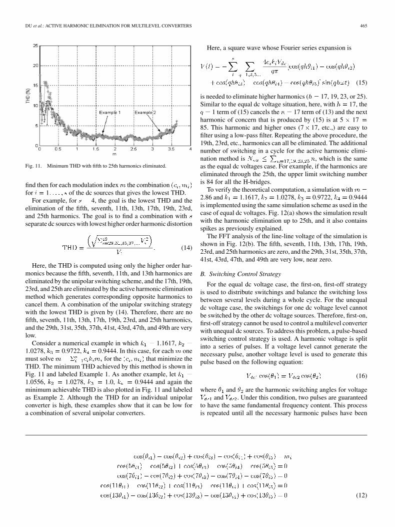
Fig. 7. (a) Simulation line-line voltage withm = 2.28 and (b) its corresponding normalized FFT analysis for harmonic elimination up to 31st.
Fig. 8. Control flow chart for first on, first off strategy.
performed. Here, the simulation scheme uses the computed con-trol signals to output ideal phase voltages, from which line-linevoltages are found. The line-line voltage and its normalized FFTanalysis are shown in Fig. 7. As expected, the line-line voltage
Fig. 9. Five-angle unipolar switching output.
has no triplen harmonics and the first nonzero harmonic is the35th harmonic. There are some spikes in the line-line voltagedue in part to the subtraction of one phase voltage from anotherand in part due to the switching by the multilevel converter toeliminate higher order harmonics.
C. Switching Controls
To balance the switching loss during a whole cycle, thefirst-on, first-off strategy is employed to control the switchingfor equal dc voltage situation. The idea for first-on, first-offstrategy is to switch the active devices in a rotational patternsuch that this strategy distributes the switching times betweenseveral levels, and each level has about the same averageswitching times in a cycle. This strategy can also balance theload between several levels. The control flowchart is shown inFig. 8. The strategy works as follows: If the next output voltageis higher than the previous voltage, the strategy picks the nextavailable switch in the switch table and turns it on. This processis repeated until the output voltage reaches the desired voltage.A similar procedure is used when the next output voltage islower than the previous voltage. This process continues untilthe voltage for a whole cycle has been synthesized.
464 IEEE TRANSACTIONS ON POWER ELECTRONICS, VOL. 21, NO. 2, MARCH 2006
Fig. 10. (a) Five-angle solutions versus m and (b) corresponding THD versus m.
III. HARMONIC ELIMINATION FOR MULTILEVEL CONVERTER
WITH UNEQUAL dc VOLTAGES
A. Decoupled Control and Harmonic Elimination forMultilevel Converter with Unequal dc Voltages
To extend the active harmonic elimination method to cas-caded H-bridge multilevel converters with unequal dc voltages,the multilevel converter must be controlled as a set of de-coupled, independent H-bridges. Here, a five-angle unipolarswitching scheme is used to control each H-bridge, whoseoutput is shown in Fig. 9. Another approach for harmonicelimination with bipolar waveforms has been described in [16].
The Fourier series expansion of the output voltage waveformas shown in Fig. 9 is
(10)
similar to the equal dc voltage situation, the switching anglescan be used to determine the fundamental frequency magni-tude and harmonic contents. Here, the fifth, seventh, 11th, and13th order harmonics are chosen to be eliminated. That is, theswitching angles must satisfy (11), shown at the bottom of thepage.
The resultant method described in [11] is again used to findthe solutions (when they exist) again. The switching angles ( ,
, , , and ) solutions versus the modulation indexare shown in Fig. 10(a) and (b) which shows the THD corre-sponding to these solutions.
As seen from the switching angle solutions shown inFig. 10(a), the solutions exist in a range of the modulationindices from 0 to 0.91. Some modulation indices have nosolutions, while there are multiple solution sets for other mod-ulation indices.
Fig. 10(b) shows that different solution sets have differentTHD values, and that the THD is high for the low modulationindex range.
A cascaded H-bridge multilevel converter can be viewedas several unipolar converters connected in series, and theseunipolar converters can each be controlled independently. Thecontrol method inherently cannot generate low order harmonicsbecause each individual unipolar converter does not generatelow order harmonics even with unequal dc voltage sources.Each unipolar converter for 1 (here is the numberof dc voltage sources) is required to satisfy the equationsdescribed in (11), i.e., (12), shown at the bottom of the nextpage. The whole output voltage of the multilevel converter canbe expressed as
(13)
The total modulation index ,where is the nominal dc voltage, is the th dc voltageand (with ) is a “combination coefficient.”If is 1, the unipolar converter outputs negative voltage; if
is 0, the unipolar converter output is zero; and if is 1, theunipolar converter outputs positive voltage. For convenience,let so that . The goal is to
(11)
DU et al.: ACTIVE HARMONIC ELIMINATION FOR MULTILEVEL CONVERTERS 465
Fig. 11. Minimum THD with fifth to 25th harmonics eliminated.
find then for each modulation index the combinationfor 1 of the dc sources that gives the lowest THD.
For example, for 4, the goal is the lowest THD and theelimination of the fifth, seventh, 11th, 13th, 17th, 19th, 23rd,and 25th harmonics. The goal is to find a combination withseparate dc sources with lowest higher order harmonic distortion
(14)
Here, the THD is computed using only the higher order har-monics because the fifth, seventh, 11th, and 13th harmonics areeliminated by the unipolar switching scheme, and the 17th, 19th,23rd, and 25th are eliminated by the active harmonic eliminationmethod which generates corresponding opposite harmonics tocancel them. A combination of the unipolar switching strategywith the lowest THD is given by (14). Therefore, there are nofifth, seventh, 11th, 13th, 17th, 19th, 23rd, and 25th harmonics,and the 29th, 31st, 35th, 37th, 41st, 43rd, 47th, and 49th are verylow.
Consider a numerical example in which 1.1617,1.0278, 0.9722, 0.9444. In this case, for each onemust solve for the that minimize theTHD. The minimum THD achieved by this method is shown inFig. 11 and labeled Example 1. As another example, let1.0556, 1.0278, 1.0, 0.9444 and again theminimum achievable THD is also plotted in Fig. 11 and labeledas Example 2. Although the THD for an individual unipolarconverter is high, these examples show that it can be low fora combination of several unipolar converters.
Here, a square wave whose Fourier series expansion is
(15)
is needed to eliminate higher harmonics ( 17, 19, 23, or 25).Similar to the equal dc voltage situation, here, with 17, the
1 term of (15) cancels the 17 term of (13) and the nextharmonic of concern that is produced by (15) is at 5 1785. This harmonic and higher ones (7 17, etc.,) are easy tofilter using a low-pass filter. Repeating the above procedure, the19th, 23rd, etc., harmonics can all be eliminated. The additionalnumber of switching in a cycle for the active harmonic elimi-nation method is , which is the sameas the equal dc voltages case. For example, if the harmonics areeliminated through the 25th, the upper limit switching numberis 84 for all the H-bridges.
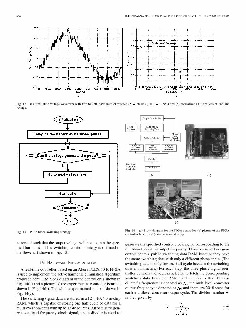
To verify the theoretical computation, a simulation with2.86 and 1.1617, 1.0278, 0.9722, 0.9444is implemented using the same simulation scheme as used in thecase of equal dc voltages. Fig. 12(a) shows the simulation resultwith the harmonic elimination up to 25th, and it also containsspikes as previously explained.
The FFT analysis of the line-line voltage of the simulation isshown in Fig. 12(b). The fifth, seventh, 11th, 13th, 17th, 19th,23rd, and 25th harmonics are zero, and the 29th, 31st, 35th, 37th,41st, 43rd, 47th, and 49th are very low, near zero.
B. Switching Control Strategy
For the equal dc voltage case, the first-on, first-off strategyis used to distribute switchings and balance the switching lossbetween several levels during a whole cycle. For the unequaldc voltage case, the switchings for one dc voltage level cannotbe switched by the other dc voltage sources. Therefore, first-on,first-off strategy cannot be used to control a multilevel converterwith unequal dc sources. To address this problem, a pulse-basedswitching control strategy is used. A harmonic voltage is splitinto a series of pulses. If a voltage level cannot generate thenecessary pulse, another voltage level is used to generate thispulse based on the following equation:
(16)
where and are the harmonic switching angles for voltageand . Under this condition, two pulses are guaranteed
to have the same fundamental frequency content. This processis repeated until all the necessary harmonic pulses have been
(12)
466 IEEE TRANSACTIONS ON POWER ELECTRONICS, VOL. 21, NO. 2, MARCH 2006
Fig. 12. (a) Simulation voltage waveform with fifth to 25th harmonics eliminated (f = 60 Hz) (THD = 1.79%) and (b) normalized FFT analysis of line-linevoltage.
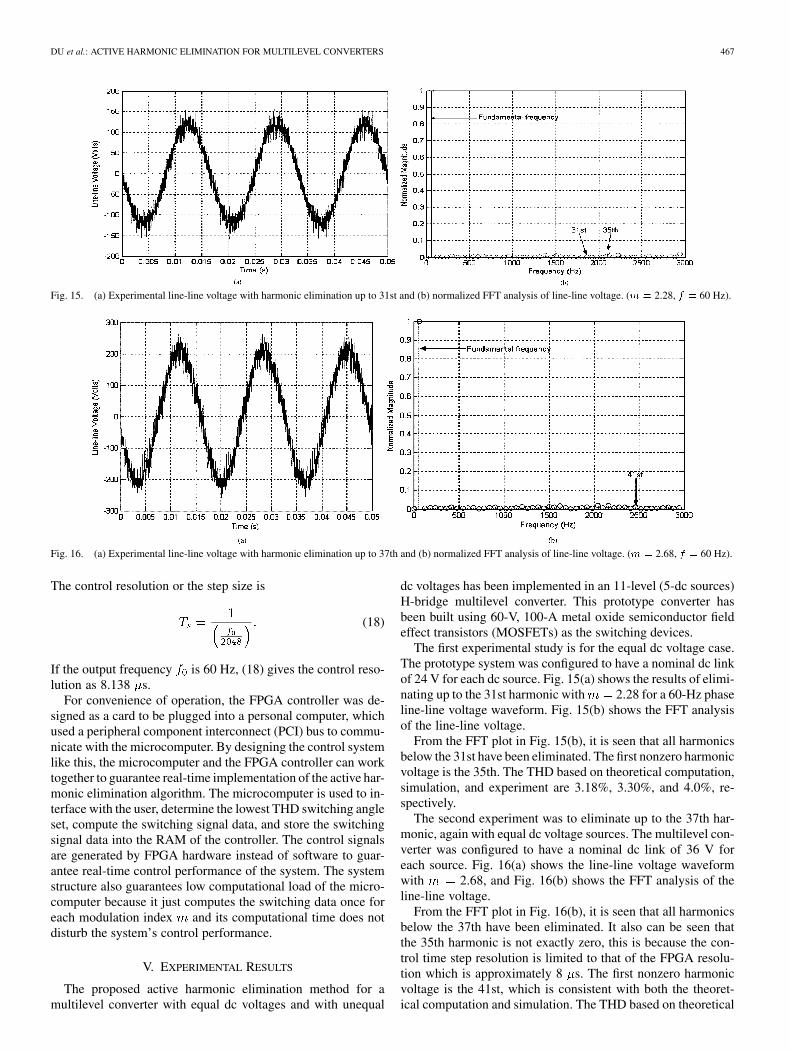
Fig. 13. Pulse based switching strategy.
generated such that the output voltage will not contain the spec-ified harmonics. This switching control strategy is outlined inthe flowchart shown in Fig. 13.
IV. HARDWARE IMPLEMENTATION
A real-time controller based on an Altera FLEX 10 K FPGAis used to implement the active harmonic elimination algorithmproposed here. The block diagram of the controller is shown inFig. 14(a) and a picture of the experimental controller board isshown in Fig. 14(b). The whole experimental setup is shown inFig. 14(c).
The switching signal data are stored in a 12 1024 b in-chipRAM, which is capable of storing one half cycle of data for amultilevel converter with up to 13 dc sources. An oscillator gen-erates a fixed frequency clock signal, and a divider is used to
Fig. 14. (a) Block diagram for the FPGA controller, (b) picture of the FPGAcontroller board, and (c) experimental setup.
generate the specified control clock signal corresponding to themultilevel converter output frequency. Three phase address gen-erators share a public switching data RAM because they havethe same switching data with only a different phase angle. (Theswitching data is only for one half cycle because the switchingdata is symmetric.) For each step, the three-phase signal con-troller controls the address selector to fetch the correspondingswitching data from the RAM to the output buffer. The os-cillator’s frequency is denoted as , the multilevel converteroutput frequency is denoted as , and there are 2048 steps foreach multilevel converter output cycle. The divider numberis then given by
(17)
DU et al.: ACTIVE HARMONIC ELIMINATION FOR MULTILEVEL CONVERTERS 467
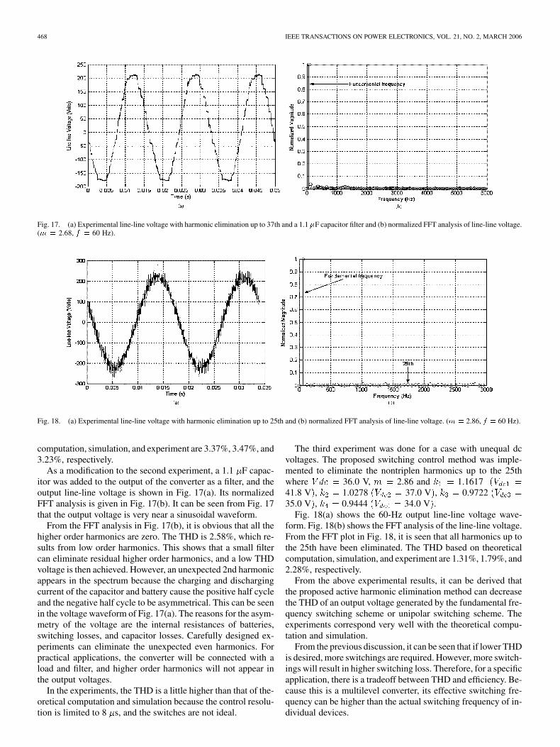
Fig. 15. (a) Experimental line-line voltage with harmonic elimination up to 31st and (b) normalized FFT analysis of line-line voltage. (m = 2.28, f = 60 Hz).
Fig. 16. (a) Experimental line-line voltage with harmonic elimination up to 37th and (b) normalized FFT analysis of line-line voltage. (m = 2.68, f = 60 Hz).
The control resolution or the step size is
(18)
If the output frequency is 60 Hz, (18) gives the control reso-lution as 8.138 s.
For convenience of operation, the FPGA controller was de-signed as a card to be plugged into a personal computer, whichused a peripheral component interconnect (PCI) bus to commu-nicate with the microcomputer. By designing the control systemlike this, the microcomputer and the FPGA controller can worktogether to guarantee real-time implementation of the active har-monic elimination algorithm. The microcomputer is used to in-terface with the user, determine the lowest THD switching angleset, compute the switching signal data, and store the switchingsignal data into the RAM of the controller. The control signalsare generated by FPGA hardware instead of software to guar-antee real-time control performance of the system. The systemstructure also guarantees low computational load of the micro-computer because it just computes the switching data once foreach modulation index and its computational time does notdisturb the system’s control performance.
V. EXPERIMENTAL RESULTS
The proposed active harmonic elimination method for amultilevel converter with equal dc voltages and with unequal
dc voltages has been implemented in an 11-level (5-dc sources)H-bridge multilevel converter. This prototype converter hasbeen built using 60-V, 100-A metal oxide semiconductor fieldeffect transistors (MOSFETs) as the switching devices.
The first experimental study is for the equal dc voltage case.The prototype system was configured to have a nominal dc linkof 24 V for each dc source. Fig. 15(a) shows the results of elimi-nating up to the 31st harmonic with 2.28 for a 60-Hz phaseline-line voltage waveform. Fig. 15(b) shows the FFT analysisof the line-line voltage.
From the FFT plot in Fig. 15(b), it is seen that all harmonicsbelow the 31st have been eliminated. The first nonzero harmonicvoltage is the 35th. The THD based on theoretical computation,simulation, and experiment are 3.18%, 3.30%, and 4.0%, re-spectively.
The second experiment was to eliminate up to the 37th har-monic, again with equal dc voltage sources. The multilevel con-verter was configured to have a nominal dc link of 36 V foreach source. Fig. 16(a) shows the line-line voltage waveformwith 2.68, and Fig. 16(b) shows the FFT analysis of theline-line voltage.
From the FFT plot in Fig. 16(b), it is seen that all harmonicsbelow the 37th have been eliminated. It also can be seen thatthe 35th harmonic is not exactly zero, this is because the con-trol time step resolution is limited to that of the FPGA resolu-tion which is approximately 8 s. The first nonzero harmonicvoltage is the 41st, which is consistent with both the theoret-ical computation and simulation. The THD based on theoretical
468 IEEE TRANSACTIONS ON POWER ELECTRONICS, VOL. 21, NO. 2, MARCH 2006
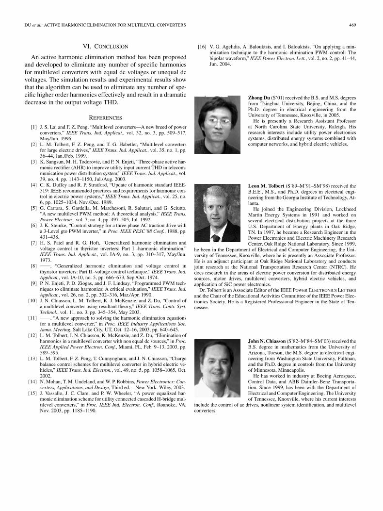
Fig. 17. (a) Experimental line-line voltage with harmonic elimination up to 37th and a 1.1 �F capacitor filter and (b) normalized FFT analysis of line-line voltage.(m = 2.68, f = 60 Hz).
Fig. 18. (a) Experimental line-line voltage with harmonic elimination up to 25th and (b) normalized FFT analysis of line-line voltage. (m = 2.86, f = 60 Hz).
computation, simulation, and experiment are 3.37%, 3.47%, and3.23%, respectively.
As a modification to the second experiment, a 1.1 F capac-itor was added to the output of the converter as a filter, and theoutput line-line voltage is shown in Fig. 17(a). Its normalizedFFT analysis is given in Fig. 17(b). It can be seen from Fig. 17that the output voltage is very near a sinusoidal waveform.
From the FFT analysis in Fig. 17(b), it is obvious that all thehigher order harmonics are zero. The THD is 2.58%, which re-sults from low order harmonics. This shows that a small filtercan eliminate residual higher order harmonics, and a low THDvoltage is then achieved. However, an unexpected 2nd harmonicappears in the spectrum because the charging and dischargingcurrent of the capacitor and battery cause the positive half cycleand the negative half cycle to be asymmetrical. This can be seenin the voltage waveform of Fig. 17(a). The reasons for the asym-metry of the voltage are the internal resistances of batteries,switching losses, and capacitor losses. Carefully designed ex-periments can eliminate the unexpected even harmonics. Forpractical applications, the converter will be connected with aload and filter, and higher order harmonics will not appear inthe output voltages.
In the experiments, the THD is a little higher than that of the-oretical computation and simulation because the control resolu-tion is limited to 8 s, and the switches are not ideal.
The third experiment was done for a case with unequal dcvoltages. The proposed switching control method was imple-mented to eliminate the nontriplen harmonics up to the 25thwhere 36.0 V, 2.86 and 1.161741.8 V , 1.0278 37.0 V , 0.972235.0 V , 0.9444 34.0 V .
Fig. 18(a) shows the 60-Hz output line-line voltage wave-form. Fig. 18(b) shows the FFT analysis of the line-line voltage.From the FFT plot in Fig. 18, it is seen that all harmonics up tothe 25th have been eliminated. The THD based on theoreticalcomputation, simulation, and experiment are 1.31%, 1.79%, and2.28%, respectively.
From the above experimental results, it can be derived thatthe proposed active harmonic elimination method can decreasethe THD of an output voltage generated by the fundamental fre-quency switching scheme or unipolar switching scheme. Theexperiments correspond very well with the theoretical compu-tation and simulation.
From the previous discussion, it can be seen that if lower THDis desired, more switchings are required. However, more switch-ings will result in higher switching loss. Therefore, for a specificapplication, there is a tradeoff between THD and efficiency. Be-cause this is a multilevel converter, its effective switching fre-quency can be higher than the actual switching frequency of in-dividual devices.
DU et al.: ACTIVE HARMONIC ELIMINATION FOR MULTILEVEL CONVERTERS 469
VI. CONCLUSION
An active harmonic elimination method has been proposedand developed to eliminate any number of specific harmonicsfor multilevel converters with equal dc voltages or unequal dcvoltages. The simulation results and experimental results showthat the algorithm can be used to eliminate any number of spe-cific higher order harmonics effectively and result in a dramaticdecrease in the output voltage THD.
REFERENCES
[1] J. S. Lai and F. Z. Peng, “Multilevel converters—A new breed of powerconverters,” IEEE Trans. Ind. Applicat., vol. 32, no. 3, pp. 509–517,May/Jun. 1996.
[2] L. M. Tolbert, F. Z. Peng, and T. G. Habetler, “Multilevel convertersfor large electric drives,” IEEE Trans. Ind. Applicat., vol. 35, no. 1, pp.36–44, Jan./Feb. 1999.
[3] K. Sangsun, M. H. Todorovic, and P. N. Enjeti, “Three-phase active har-monic rectifier (AHR) to improve utility input current THD in telecom-munication power distribution system,” IEEE Trans. Ind. Applicat., vol.39, no. 4, pp. 1143–1150, Jul./Aug. 2003.
[4] C. K. Duffey and R. P. Stratford, “Update of harmonic standard IEEE-519: IEEE recommended practices and requirements for harmonic con-trol in electric power systems,” IEEE Trans. Ind. Applicat., vol. 25, no.6, pp. 1025–1034, Nov./Dec. 1989.
[5] G. Carrara, S. Gardella, M. Marchesoni, R. Salutari, and G. Sciutto,“A new multilevel PWM method: A theoretical analysis,” IEEE Trans.Power Electron., vol. 7, no. 4, pp. 497–505, Jul. 1992.
[6] J. K. Steinke, “Control strategy for a three phase AC traction drive witha 3-Level gto PWM inverter,” in Proc. IEEE PESC’88 Conf., 1988, pp.431–438.
[7] H. S. Patel and R. G. Hoft, “Generalized harmonic elimination andvoltage control in thyristor inverters: Part I -harmonic elimination,”IEEE Trans. Ind. Applicat., vol. IA-9, no. 3, pp. 310–317, May/Jun.1973.
[8] , “Generalized harmonic elimination and voltage control inthyristor inverters: Part II -voltage control technique,” IEEE Trans. Ind.Applicat., vol. IA-10, no. 5, pp. 666–673, Sep./Oct. 1974.
[9] P. N. Enjeti, P. D. Ziogas, and J. F. Lindsay, “Programmed PWM tech-niques to eliminate harmonics: A critical evaluation,” IEEE Trans. Ind.Applicat., vol. 26, no. 2, pp. 302–316, Mar./Apr. 1990.
[10] J. N. Chiasson, L. M. Tolbert, K. J. McKenzie, and Z. Du, “Control ofa multilevel converter using resultant theory,” IEEE Trans. Contr. Syst.Technol., vol. 11, no. 3, pp. 345–354, May 2003.
[11] , “A new approach to solving the harmonic elimination equationsfor a multilevel converter,” in Proc. IEEE Industry Applications Soc.Annu. Meeting, Salt Lake City, UT, Oct. 12–16, 2003, pp. 640–645.
[12] L. M. Tolbert, J. N. Chiasson, K. McKenzie, and Z. Du, “Elimination ofharmonics in a multilevel converter with non equal dc sources,” in Proc.IEEE Applied Power Electron. Conf., Miami, FL, Feb. 9–13, 2003, pp.589–595.
[13] L. M. Tolbert, F. Z. Peng, T. Cunnyngham, and J. N. Chiasson, “Chargebalance control schemes for multilevel converter in hybrid electric ve-hicles,” IEEE Trans. Ind. Electron., vol. 49, no. 5, pp. 1058–1065, Oct.2002.
[14] N. Mohan, T. M. Undeland, and W. P. Robbins, Power Electronics: Con-verters, Applications, and Design, Third ed. New York: Wiley, 2003.
[15] J. Vassallo, J. C. Clare, and P. W. Wheeler, “A power equalized har-monic elimination scheme for utility connected cascaded H-bridge mul-tilevel converters,” in Proc. IEEE Ind. Electron. Conf., Roanoke, VA,Nov. 2003, pp. 1185–1190.
[16] V. G. Agelidis, A. Balouktsis, and I. Balouktsis, “On applying a min-imization technique to the harmonic elimination PWM control: Thebipolar waveform,” IEEE Power Electron. Lett., vol. 2, no. 2, pp. 41–44,Jun. 2004.
Zhong Du (S’01) received the B.S. and M.S. degreesfrom Tsinghua University, Bejing, China, and thePh.D. degree in electrical engineering from theUniversity of Tennessee, Knoxville, in 2005.
He is presently a Research Assistant Professorat North Carolina State University, Raleigh. Hisresearch interests include utility power electronicssystems, distributed energy systems combined withcomputer networks, and hybrid electric vehicles.
Leon M. Tolbert (S’89–M’91–SM’98) received theB.E.E., M.S., and Ph.D. degrees in electrical engi-neering from the Georgia Institute of Technology, At-lanta.
He joined the Engineering Division, LockheedMartin Energy Systems in 1991 and worked onseveral electrical distribution projects at the threeU.S. Department of Energy plants in Oak Ridge,TN. In 1997, he became a Research Engineer in thePower Electronics and Electric Machinery ResearchCenter, Oak Ridge National Laboratory. Since 1999,
he been in the Department of Electrical and Computer Engineering, the Uni-versity of Tennessee, Knoxville, where he is presently an Associate Professor.He is an adjunct participant at Oak Ridge National Laboratory and conductsjoint research at the National Transportation Research Center (NTRC). Hedoes research in the areas of electric power conversion for distributed energysources, motor drives, multilevel converters, hybrid electric vehicles, andapplication of SiC power electronics.
Dr. Tolbert is an Associate Editor of the IEEE POWER ELECTRONICS LETTERS
and the Chair of the Educational Activities Committtee of the IEEE Power Elec-tronics Society. He is a Registered Professional Engineer in the State of Ten-nessee.
John N. Chiasson (S’82–M’84–SM’03) received theB.S. degree in mathematics from the University ofArizona, Tucson, the M.S. degree in electrical engi-neering from Washington State University, Pullman,and the Ph.D. degree in controls from the Universityof Minnesota, Minneapolis.
He has worked in industry at Boeing Aerospace,Control Data, and ABB Daimler-Benz Transporta-tion. Since 1999, has been with the Department ofElectrical and Computer Engineering, The Universityof Tennessee, Knoxville, where his current interests
include the control of ac drives, nonlinear system identification, and multilevelconverters.