Embed Size (px)
Citation preview

IEEE TRANSACTIONS ON MICROWAVE THEORY AND TECHNIQUES, VOL. 54, NO. 7, JULY 2006 3001
Operation, System Architectures, and PhysicalLayer Design Considerations of Distributed
MAC Protocols for UWBNathaniel J. August, Member, IEEE, and Dong Sam Ha, Senior Member, IEEE
Abstract—Impulse-based ultra wideband (I-UWB) is an at-tractive radio technology for large ad hoc and sensor networksdue to its robustness to harmful multipath effects, sub-centimeterranging ability, simple hardware, and low radiated power. Toscale to large sizes, networks often implement distributed mediumaccess control (MAC) protocols. However, most MAC protocolsfor I-UWB are centralized, and they target small wireless personalarea networks and cellular networks. We propose three distributedMAC protocols suitable for I-UWB. Two multichannel protocols,called multichannel pulse sense multiple access (M-PSMA) andmultichannel ALOHA achieve high aggregate throughput. Abusy-signal protocol, called busy-signal multiple access (BSMA),reduces the energy wasted from re-transmitted packets. Thispaper describes the three protocols in terms of the protocol’soperation, the supporting system architecture, and the I-UWBphysical layer. Physical layer simulations confirm the feasibilityof implementing the proposed systems and also provide parame-ters for network simulations. Network simulations show that thethroughput of M-PSMA exceeds that of a centralized time-divisionmultiple-access protocol and that the energy efficiency of BSMAfar surpasses that of other distributed protocols.
Index Terms—Ad hoc and sensor networks, busy-signal multipleaccess (BSMA), medium access control (MAC), pulse sense, ultra-wideband (UWB).
I. INTRODUCTION
IMPULSE-BASED ultra-wideband (I-UWB) is an attractiveradio technology for ad hoc and sensor networks due to its
low radiated power, robustness to harmful multipath effects,sub-centimeter ranging ability, and simple hardware [1]–[4].Most medium access control (MAC) protocols for I-UWB arecentralized, and they target small wireless personal area net-works (WPANs) and cellular networks [5]–[18]. For ad hocand sensor networks with a large number of nodes, these proto-cols impose impractical constraints such as central coordination(which leads to a central point of failure), more complex hard-ware, or control traffic overhead.
Manuscript received January 2, 2006; revised March 8, 2006.N. J. August was with the Very Large Scale Integration for Telecommunica-
tions Laboratory, Bradley Department of Electrical and Computer Engineering,Virginia Polytechnic Institute and State University, Blacksburg, VA 24061USA. He is now with the Intel Corporation, Portland, OR 97124 USA (e-mail:[email protected]).
D. S. Ha is with the Very Large Scale Integration for TelecommunicationsLaboratory, Bradley Department of Electrical and Computer Engineering, Vir-ginia Polytechnic Institute and State University, Blacksburg, VA 24061 USA(e-mail: [email protected]).
Digital Object Identifier 10.1109/TMTT.2006.877424
To scale to a large size, networks generally implement dis-tributed MAC protocols because distributed protocols do notcomplicate hardware, require central coordination, or add con-trol traffic overhead [19]–[23]. In a previous study [24], we char-acterized the network performance of distributed MAC proto-cols suitable for I-UWB. In this paper, we further analyze theoperation of three MAC protocols and describe the supportingsystem architectures. In addition, this paper presents simula-tions that reflect physical layer considerations such as channeleffects. These physical layer simulations confirm the feasibilityof implementing the proposed systems and also provide param-eters for network simulations.
Two of the proposed protocols are classified as multichannelprotocols and the third is classified as a busy-signal protocol.
First, we explore the two multichannel protocols: multi-channel ALOHA (M-ALOHA) and multichannel pulse sensemultiple access (M-PSMA). Each sub-channel in M-PSMAand M-ALOHA operates at the full channel data rate, whereaseach sub-channel in a traditional multichannel protocol op-erates at a fraction of the full channel data rate. An optionalmultiuser receiver, which can receive on multiple sub-channelssimultaneously, further improves performance with moderateadditional hardware complexity.
Next, we investigate the busy-signal protocol, i.e.,busy-signal multiple access (BSMA). BSMA improves en-ergy efficiency by decreasing the number of collisions andalso by reducing the energy wasted on the collisions that dooccur. Whereas narrowband systems require two transceiversto implement a busy-tone MAC, the proposed I-UWB systemrequires only a single transceiver to save cost, power, andcircuit complexity.
This paper is organized as follows. Section II reviews I-UWBsignaling, our base transceiver architecture, and related workby others on MAC protocols. Section III focuses on the multi-channel protocols M-PSMA and M-ALOHA, while Section IVconcentrates on the busy-signal protocol BSMA. Sections IIIand IV explain the operation, system architecture, and physicallayer considerations for the proposed protocols. Sections III andSection IV also present physical layer simulation results. Sec-tion V presents network simulation results, and Section VI con-cludes this paper
II. PRELIMINARIES
A. I-UWB Signaling
An I-UWB signal consists of a series of sharp pulses withduration of a few hundred picoseconds to a few nanoseconds.
0018-9480/$20.00 © 2006 IEEE
3002 IEEE TRANSACTIONS ON MICROWAVE THEORY AND TECHNIQUES, VOL. 54, NO. 7, JULY 2006
The pulses repeat at a pulse repetition interval (PRI) that rangesfrom nanoseconds to microseconds. Our proposed MAC proto-cols benefit from I-UWB signals with a PRI in the approximaterange from 1 s to 10 ns. We claim that PRIs in this range aremoderate, as described below.
For PRIs shorter than our moderate range, systems must over-come several challenges. One challenge is that the channel delayspread starts to become longer than the PRI so an I-UWB com-munications system encounters significant inter-symbol inter-ference (ISI). Another challenge is that, as pulses appear morefrequently, each pulse must decrease in energy to meet the Fed-eral Communications Commission (FCC)’s average (over manyPRIs) power limits of 41.3 dBm/MHz [25]. In addition, theamplitude of spectral lines relative to the average power in-creases with decreasing PRI. Thus, a system designer cannot ar-bitrarily decrease the PRI to improve throughput without somecost.
For PRIs longer than our moderate range, the pulse repetitionfrequency (PRF) approaches the bandwidthof narrowband victim receivers. The FCC regulates the peakpower of a single pulse1 to prevent overloading nearby narrow-band victim receivers. Thus, a system designer cannot arbitrarilyincrease the PRI to improve the signal-to-noise ratio (SNR).
B. Base I-UWB Transceiver
Our base I-UWB transceiver targets CMOS implementationbecause the low power dissipation and low cost are suited toad hoc and sensor networks. All the critical front-end trans-ceiver components have been fabricated and tested in a 0.18- mCMOS process [26]–[29]. The fabricated components include apower amplifier (PA), variable gain amplifiers, peak detectors, alow-noise amplifier (LNA), a phase-locked loop, an analog-to-digital converter, the filters, and a transmit/receive (T/R) mech-anism. Instead of using a typical T/R switch, our system togglesthe disable inputs to the PA and LNA. This scheme improves theswitching time to 250 ps (which is much faster than our fastestPRI of 10 ns), and it avoids the additional noise and insertionloss of a T/R switch. A pulse sensor unit quickly and reliablydetects I-UWB traffic just as carrier sense detects narrowbandsignals [30]. The pulse sensor’s analog components occupy lessthan 3% of the total transceiver area, and its digital circuitryrequires a few hundred transistors. The remaining design workconsists of digital blocks for baseband signal processing and forimplementing our proposed MAC protocols.
System-level simulations and CMOS measurements of thetransceiver show that the performance is more than adequate forad hoc and sensor networks at moderate pulse rates. The trans-ceiver achieves a bit error rate (BER) of approximately 2 10for a link distance of 10 m in extreme nonline-of-sight (NLOS)channel conditions at a data rate of 100 Mb/s without channelcoding [31], [32]. Lowering the data rate (via spreading or re-ducing the pulse rate to around 50 ns, where FCC regulationsbegin to limit peak power) can increase the link distance or im-prove the BER. The transceiver dissipates an estimated 600 Wof power when actively transmitting and 180 mW when activelyreceiving. Low power design techniques, such as reduced ADC
1The peak power limit is 20 log (RBW/50 MHz), where “RBW” denotes thevictim receiver bandwidth centered on the frequency of peak UWB power [23].
resolution or sleep modes, can significantly reduce the averagepower from the active power levels [33].
Although the complete transceiver is not integrated in a singlechip, we believe that the fabrication and testing of the front-endcomponents and the simulations of the system show that thereare no significant barriers to implementing an integrated system.
C. MAC Protocols
Most MAC protocols for I-UWB are centralized, and theytarget small WPANs and cellular networks [5]–[18]. A cen-tral controller assigns concurrent transmissions to multiplesub-channels via time division multiple access (TDMA) [9],[10], time-hopping codes [5]–[8], frequency-hopping codes[11]–[14], or direct sequence codes [15]–[18]. Such central-ized multichannel approaches are a good strategy for smallnetworks with heavy traffic and strict quality of service (QoS)requirements. However, in large ad hoc and sensor networks,the centralized control does not scale well. Control trafficsignificantly increases the amount of overhead, thus wastingbandwidth and energy. Further, because nodes may not beeasily serviceable (e.g., battlefields), a central failure wouldrender the network useless.
Some multichannel protocols are modified to distributivelydetermine a transmission’s sub-channel based on the address ofthe receiver [34] or the sender [35]. However, to prevent simul-taneous transmissions to one node, these protocols incur over-head to establish a link [34], [35] and may require techniquessuch as adaptive coding to mitigate strong multiuser interfer-ence [34]. Design guidelines for distributed multichannel pro-tocols are suggested in [36]. In addition to controlling mediumaccess, a distributed management system may also control QoS[37].
Instead of altering existing I-UWB protocols to become moredistributed, we propose fundamentally distributed approachesto scale to large ad hoc and sensor networks. In a distributedprotocol, each node independently decides to transmit withoutcentral guidance. This reduces control overhead, and there isno central synchronization or central point of failure. However,as described below, adoption of some existing distributed MACprotocols is impractical for I-UWB [19]–[23].
ALOHA is a basic distributed MAC protocol that can be ap-plied to I-UWB in a straightforward manner. In ALOHA, a nodemay transmit a data packet anytime, unless it is busy with an-other packet. If the data transmission succeeds, the target noderesponds with an acknowledgment (ACK) packet. Otherwise,the source node waits a random period of time to retransmit thedata. ALOHA performs well under light traffic, but poorly underheavy traffic.
In narrowband systems, carrier sense multiple access(CSMA) improves on ALOHA by requiring a node to checkfor a busy medium before transmitting [19]–[21]. For I-UWB,a pulse sensor enables an analogous protocol, i.e., pulse sensemultiple access (PSMA) [30]. However, hidden terminal con-ditions cause poor performance in CSMA and PSMA.
Narrowband systems mitigate hidden terminal conditions viacollision avoidance (CA) with time-duplexed request-to-send(RTS) and clear-to-send (CTS) packets. For I-UWB, the RTSand CTS packets add excessive overhead in PSMA with CA

AUGUST AND HA: OPERATION, SYSTEM ARCHITECTURES, AND PHYSICAL LAYER DESIGN CONSIDERATIONS OF DISTRIBUTED MAC PROTOCOLS 3003
Fig. 1. Throughput for PSMA, PSMA/CA as acquisition time increases. Thetransmitting nodes are hidden from one another.
(PSMA/CA) [20], [38]. The narrow pulses, low radiated power,harsh channel conditions, and strict FCC power limits combineto produce long acquisition times, which results in excessivelylong preambles for the RTS and CTS packets.
Fig. 1 shows the shortcomings of PSMA and PSMA/CA ina linear network of three I-UWB nodes A–B–C. Nodes A andC are hidden from one another, and they both transmit to Bwith a 1-Mb/s data rate. The time between packets follows aPoisson distribution such that nodes A and C transmit at an av-erage of 0.5 offered load. Using serial correlation, practicalacquisition times for I-UWB range from 800 to 1600 s (800to 1600 symbols), compared to approximately 100 s for a nar-rowband system. Such long acquisition times significantly de-grade the throughput for PSMA/CA due to the overhead of theRTS and CTS packets. PSMA performs poorly due to the hiddenterminal condition. Our proposed MAC protocols exploit theunique signaling of I-UWB to improve performance over PSMAand PSMA/CA.
III. MULTICHANNEL MAC PROTOCOLS FOR I-UWB SYSTEMS
Multichannel MAC protocols are known to reduce collisionswithout the overhead of RTS and CTS packets [22]. A multi-channel MAC protocol divides a channel of bandwidth into
sub-channels of bandwidth , where is the spreadingfactor or number of time slots. Note that is not necessarilyequal to , especially in code division. Although multichannelprotocols reduce the link data rate by a factor of , they increaseoverall network throughput at high offered load. A node may se-lect from a greater number of (ideally) orthogonal sub-channelsso there is a smaller probability of collisions. However, the re-duced data rate of each sub-channel incurs a delay penalty atlow offered load.
A. Operation of M-ALOHA and M-PSMA
We propose two distributed multichannel MAC protocols,called M-ALOHA and M-PSMA, that exploit the inherently lowduty cycle of I-UWB to implement sub-channels. Depending
Fig. 2. Multichannel MAC operation [24].
on the pulse rate and channel conditions, I-UWB signals maycontain a large amount of “dead time” between pulses. Thisdead time is used to time-interleave additional sub-channels.Each sub-channel maintains the full data rate, so the networkincreases throughput without increasing delay.
In M-PSMA, nodes may transmit any time they sense an idlechannel. If a node senses activity, it waits until after the mediumis free to retransmit. A source node also waits for a random pe-riod of time to retransmit if it does not receive an acknowledge-ment. The random time period is bounded by a binary expo-nential. The operation of M-ALOHA is similar, but it does notcheck for an idle channel before transmitting.
The M-PSMA and M-ALOHA protocols provide multipletime-interleaved channels by allowing concurrent transmissionsof nonoverlapping pulse trains. During an initial reception, thereceiver may acquire (for a multiuser receiver) or ignore (for asingle-user receiver) other concurrent nonoverlapping transmis-sions. For example, in Fig. 2, two nodes sense an idle channel attime so they simultaneously start transmitting at time tothe same receiver. The receiver detects an incoming transmis-sion through the pulse sensor. Transmitter2 is closer, so its firstpulse arrives at time , while Transmitter1’s first pulse arrivesat . After some time, a single acquisition circuit detects thearrival time of the two pulse trains within a PRI. If the receiveris a multiuser receiver, two clock recovery circuits track Trans-mitter2’s pulse train starting at and Transmitter1’s pulse trainstarting at . The receiver time-shares a single demodulatorbetween the incoming signals. If the transmissions target dif-ferent nodes, the receiver would track and decode only its owntransmission. If the receiver is single user, it would track onlyTransmitter2’s pulse train and ignore Transmitter1’s pulse trainbecause Transmitter2’s pulse train precedes Transmitter1’s.
If two or more nodes transmit simultaneously, a collision canoccur only if the pulses (including multipaths) overlap withina PRI. To quantify this, consider a version of M-ALOHA thatallows up to sub-slots2 per PRI, so there may be maximumof simultaneous transmissions that do not share any common
2We use the term “sub-slot” to denote the number of multipath-delay-spread-sized time units within a PRI. This is to differentiate a sub-slot from a slot, whichoften denotes a packet-sized unit of time in a slotted MAC protocol.

3004 IEEE TRANSACTIONS ON MICROWAVE THEORY AND TECHNIQUES, VOL. 54, NO. 7, JULY 2006
sub-slots. For nodes transmitting, the probability that twoor more nodes share a slot is
(1)
We now consider the performance of a system withslots because a long multipath delay spread is 25 ns [39], a1-Mp/s pulse rate has a PRI of 1000 ns, and .From (1), it is improbable that two concurrenttransmissions overlap in time at a single receiver.
gradually approaches 100% as increases to , but italso becomes increasingly improbable that many more than twonodes transmit concurrently because the number of possible in-terfering transmissions is limited by the number of neighbors.To ensure a connected topology in large networks with powercontrol, note that the critical number of neighbors is approxi-mately , where is the total number of nodes [40].
The probability that neighbor nodes transmit during apacket time is designated ( nodes transmit), andthis probability depends on the application. For illustrativepurposes, we assume the nodes transmit with a Poisson dis-tribution at a mean rate of packets per packet time. Sincethe number of nodes transmitting is independent of the time oftransmission within a PRI, and are independent. Theprobabilities of collision for the proposed M-ALOHA protocoland for a single-channel protocol are
(2)
(3)
For such that , must be less thanbecause . This decreased probability
of collision is a huge benefit compared to a single-channel pro-tocol in which the probability of collision is 100% if two or morenodes transmit simultaneously.
For the proposed multichannel I-UWB protocols, the proba-bility of a collision remains low even when is greater thanthe number of packets per packet time, i.e., the protocol canoffer a throughput larger than the aggregate data rate. For ex-ample, with , the above M-ALOHA protocol has a 90%
chance of a successful transmission, whereasa single channel protocol has only a 20%chance of success. Thus, M-ALOHA and M-PSMA can miti-gate the reduction in throughput caused by collisions withoutthe overhead of handshaking packets.
B. System Architecture
For each sub-channel, the receiver in Section II (in either asingle-userormultiuserconfiguration)collectssignalenergyovera time window ns around the strongest multipath clusterfrom the signal of interest. The receiver can resolve a single signalwithin so 3 ns is also the minimum sub-slot time.
Multiuser receivers, which can receive on several sub-chan-nels concurrently, improve performance over a single channel
receiver [22]. However, traditional multiuser receivers are un-suitable for large ad hoc and sensor networks. A receiver undera TDMA protocol is inherently multiuser, but it requires cen-tralized control. A multiuser receiver under a code-division pro-tocol requires separate correlators for each sub-channel, and amultiuser receiver under a frequency-division protocol requiresa separate front-end for each channel.
Under M-PSMA and M-ALOHA, an I-UWB system can im-plement a multiuser receiver with simpler hardware and no cen-tral control [41]. Each supported sub-channel requires only adedicated clock recovery circuit. If the receiver detects morethan one incoming transmission during acquisition, it assignsan available clock recovery circuit to each nonoverlapping in-coming transmission. After acquisition, the acquisition circuitcontinues to look for nonoverlapping transmissions. Since theresolvable transmissions do not overlap, they may time-share asingle front end and a single decision block.
C. Physical Layer Design Considerations
When the pulses from two interleaved pulse trains appearclose in time to each other, the multipath spread from the firstpulse interferes with the second. The effective interference isdetermined by the delay between the pulses, the signal to inter-fering signal (S/I) level, the channel power delay profile, and thechannel delay spread. The receiver must separate the intendedsignal from the received signal in (4) as follows:
(4)
where
data signal from a node , the set of all nodeswhose transmissions experience a collision;data signal from a node , the set of all nodeswhose transmissions experience interference, butnot a collision;data signal from a node , the set of all nodeswhose transmissions do not experience interferenceor a collision;
, time offset of arrival within a PRI of signal fromnode . , s.t. for andreceiver time window ;time offset of arrival within a PRI of signal fromnode . , s.t. for ;also, , , for , where isthe multipath delay spread;time offset of arrival within a PRI of signal fromnode . , , for ;channel response from node to the receiver;
channel response from node to the receiver;
channel response from node to the receiver;
noise at the receiver.
As implied by (4), nodes can be broken into the three groups, , and . First, consider the case with a received transmission

AUGUST AND HA: OPERATION, SYSTEM ARCHITECTURES, AND PHYSICAL LAYER DESIGN CONSIDERATIONS OF DISTRIBUTED MAC PROTOCOLS 3005
Fig. 3. Interference from overlapping transmissions.
from node . Since the receiver in Section II cannot differ-entiate between signals that arrive within one time windowof each other, it discards all transmissions from nodes in group
, and they are considered as collisions.Using physical layer simulations in Agilent’s Advanced De-
sign System (ADS), we characterize the interference from anode to a node or . The simulations use binaryphase-shift keying (BPSK) modulation, and the second arrivingpulse is 6 dB over the receiver’s minimum sensitivity level.The power level of results in S/I levels from 10 dB to
10 dB to encompass a 10-m radius. Although an S/I level of10 dB places the average interference power below the sen-
sitivity level, the instantaneous power may affect reception. Wealso vary the delay between the pulses. We start with adelay of (3 ns) and stop when no longer interferes with
. Fig. 3 shows simulation results from an average of 20random implementations of the IEEE 802.15.3a channel modelCM4 [39]. As expected, the interference decreases as the delaybetween pulses increases and as the S/I ratio increases.
For a node , the pulses arrive at the receiver at leastone time window later than a pulse from node , and multi-paths from interfere with . For example, with an S/Iof 10 dB, Fig. 3 shows that adds an average of approx-imately 8.5 dB of noise to when the time difference isand an average of 2 dB of noise when the time difference is tworms delay spreads.
For a node , multipaths from do not significantlyinterfere with . We consider a transmission to be from anode in if it experiences an effective noise level less than acutoff of 0.1 dB. For an S/I of 10 dB, Fig. 3 shows that thisoccurs around a time difference of five rms delay spreads.
Results similar to Fig. 3 characterize the interference amongtransmissions for the network simulations in Section V. Insteadof using an average, each link has a unique channel model. Theadded noise is obtained for each pair-wise set of transmissionsfrom lookup tables indexed by the S/I ratio, the channel model,and the time difference between pulses.
IV. BUSY-SIGNAL MAC PROTOCOL FOR I-UWB SYSTEMS
M-ALOHA and M-PSMA improve throughput, but collisionsstill waste energy by forcing nodes to retransmit entire packets.
Fig. 4. Types of duplexing [45].
Collision detection or CA could reduce the wasted energy. How-ever, collision detection normally requires an additional trans-ceiver to duplex feedback signals in a frequency band separatefrom the data. From Section II, CA adds excessive overhead inI-UWB. An energy-efficient busy-signal MAC protocol, calledBSMA, that avoids the hardware cost of collision detection andthe overhead of CA is proposed here.
A busy signal provides three important services to the MAClayer, which are: 1) preventing nodes within range of the des-tination from initiating a transmission; 2) informing the sourcenode of a successful transmission; and 3) requesting the sourcenode to terminate transmission of a corrupt packet so it doesnot waste energy transmitting the entire packet. The busy signaleffectively acts as a symbol-level ACK. BSMA may require abusy signal to be emitted by any node that detects a transmis-sion [42], or by the destination node only [43]; or first, by anynode that detects a transmission and then, by only the destina-tion node after address decoding is complete [23]. Our imple-mentation follows that in [23].
A. Duplexing
To implement a busy signal, a transceiver must be capableof full duplex operation [44]. Narrowband radios implementfull duplex operation with frequency division duplexing (FDD),which requires two transceivers in different frequency bands.The FDD system in Fig. 4(a) can transmit a busy signal and re-ceive a data signal simultaneously, but the additional frequencyband is inefficient in hardware complexity, power dissipation,and spectral usage.
Since FDD is expensive, narrowband systems usually im-plement time-domain duplexing (TDD), as shown in Fig. 4(b).CA protocols use TDD, and the acquisition overhead for eachtime-duplexed packet incurs penalties in throughput, energy ef-ficiency, and latency. Further, a TDD system cannot detect apacket error until after the transaction completes, thus it wastesenergy transmitting corrupted data. TDD is especially unattrac-tive for energy-sensitive networks operating in harsh channelconditions
We propose a fine-grained half duplex for I-UWB thatachieves full duplex performance with a single transceiver.

3006 IEEE TRANSACTIONS ON MICROWAVE THEORY AND TECHNIQUES, VOL. 54, NO. 7, JULY 2006
Fig. 5. Full duplex system architectures [24].
An I-UWB signal is not continuous in time like a narrowbandsignal, thus the idle time between data pulses can serve asa feedback channel for a busy signal. The I-UWB system inFig. 4(c) achieves full duplex performance without the energy,latency, and throughput penalty of the TDD system and withoutthe additional frequency band of the FDD system. Startingin receive mode, a transceiver receives a data pulse. It thenswitches to transmit mode and transmits a busy-signal pulse.After transmitting, it switches to receive mode and preparesfor the next data pulse. The fine-grained half duplex switchesbetween receive and transmit modes on a symbol level, but itappears as full duplex at the MAC level.
B. System Architecture
Fig. 5 compares an FDD architecture for narrowband radiosto the proposed fine-grained half duplex architecture for I-UWBradios. An ad hoc network has no base station to translate be-tween frequency bands for inter-node communication. There-fore, the narrowband radio in Fig. 5(a) must be capable of op-erating in either band, depending upon whether it is a sourceor destination node. The dual bands result in a radio, with twotransceivers and two circulators, that demands more than twicethe power and hardware cost of a single transceiver. The feed-back channel also degrades spectral efficiency.
With the proposed I-UWB system in Fig. 5(b), the low dutycycle allows a single transceiver to access a feedback channel inthe same frequency band as the transmitted data. Since the datasignal and the busy signal share a band, they also share RF cir-cuitry. The switching time between transmit and receive modesdetermines the minimum PRI. The receiver in Section II togglesthe disable inputs to the PA and the LNA to achieve a switchingtime of 250 ps, which is much faster than our fastest PRI of10 ns. The proposed I-UWB transceiver significantly reducescircuit cost and power dissipation as compared to a narrowbandFDD transceiver. Further, the system leverages the low transmitpower of I-UWB by transmitting a busy signal for the durationof a successful transaction, while only periodically checking fora busy signal.
C. Physical Layer Design Considerations
A node under BSMA can be a source node, a destinationnode, or an idle node. The busy signal should not degrade datareception at a destination node, and it should be easily detectableby a source node or an idle node with data to transmit. Interfer-ence complicates these goals. After the destination node trans-mits a busy signal, the multipath channel causes a long ringdown time, and some of the busy-signal multipaths could inter-fere with data reception. Likewise, the source node’s data signalmay interfere with busy-signal detection. When multiple nodesemit busy signals, they may interfere with both data receptionand busy-signal detection. The received signal for a node
is given in (5) as follows:
(5)
where
impulse response of the PA in state on off ;
impulse response of the LNA in stateoff on ;
signal transmitted by node (data or busysignal);signal received by node from its link partner,node ;signal from a node , the set of all nodes
transmitting a busy signal, including ifit is a destination;signal from a node , the set of all nodes
transmitting a data signal, including if itis a source;channel impulse response of any node to node;
propagation delay from any node to node ;
internal delay from the transmitter to thereceiver;the receiver noise at node .
A node should mitigate the strong interference from its owntransmission such that ideally
(6)
Since the switching time is not instantaneous, we enable/disablethe PA/LNA such that either or is always off. Thus, toprevent interference from , the timing sequence consists of0.25 ns for the transition on off , 0.25 ns for thetransition off on , the transmitted pulsewidth time(usually less than 1 ns), 0.25 ns for the transition on
off , and 0.25 ns for the transition off on .

AUGUST AND HA: OPERATION, SYSTEM ARCHITECTURES, AND PHYSICAL LAYER DESIGN CONSIDERATIONS OF DISTRIBUTED MAC PROTOCOLS 3007
(a) Link Distance =c*PRI. (b) Link Distance= 0.75*c*PRI.
Fig. 6. Overlap effect at source node [45].
Next, a node should separate from other data and busysignals and from its own reflected multipaths such that ideally
(7)
To mitigate the interference in (7), we separate the data signalfrom the busy signal. Spreading the busy signal, as in direct-se-quenceultra-wideband(DS-UWB),differentiates thebusysignalfrom the data signal [17]. To prevent multiple busy signals fromcombining destructively, the DS-UWB code minimizes autocor-relation. Orthogonal pulse shapes also separate the busy signalfrom the data signal. Finally, node estimates and equalizes thereflections from its own transmitted signal. Such equalization isrelatively simple because the signal is known.
The phenomenon of overlap may also degrade performance[44], [45]. Depending on the link distance, a busy-signal pulsemay overlap a data pulse in time at either the source node or des-tination node. For clarity, we allow the destination to time itsbusy-signal transmission to avoid any overlap with the receiveddata signal. Thus, a source node may lose a portion of the busysignalwhen it transmitsadatapulsewith itsPAenabled onand its LNA disabled off . Fig. 6 illustrates overlap at asource node. At Time 1, the source node transmits a pulse, whicharrives one propagation time , later at the destination nodeat Time 2. At Time 3, the destination sends a busy-signal pulseexactly s after the arrival of the first data pulse. Fi-nally, at Time 4, the source node receives the busy-signal pulse.In Fig. 6(a), the link distance is m so the round-trip prop-agation time is s. Therefore, the busy-signal pulse arrives
s after the corresponding data pulse. In Fig. 6(b), thelink distance is m, the round-trip propagation timeis s, and the busy-signal pulse arrives s after thecorresponding data pulse. Since the source node is transmitting,it loses energy from the busy signal. Note that Fig. 6 shows onlythe first multipath of a busy signal; in reality, a receiver could de-tect some portion of the multipath energy.
A source node should mitigate overlap such that ideally
(8)
To completely avoid overlap, both the source and destinationnodes may wait for the maximum multipath delay spread of
between receiving a busy-signal (data) pulse andtransmitting a data (busy signal) pulse. Thus, for a maximumlink distance of , a PRI can satisfy (8) if [45]
(9)
At shorter PRIs, the source node may lose up to 2 ns of thebusy-signal energy from overlap and from the enable/disabletiming resulting from (6). The DS-UWB scheme reduces theenergy loss by spreading the busy-signal energy over a longertime period. Further, the energy from multipath reflections isavailable over a much longer period than 2 ns.
To mitigate the interference in (7), we have suggested threetechniques, which are: 1) separating the busy signal from thedata signal via DS-UWB and orthogonal pulse shapes; 2) mini-mizing destructive busy-signal interference by using a spreadingcode with low autocorrelation; and 3) equalizing self-interfer-ence. Fig. 7 compares the simulated performance of our pro-posed techniques (labeled Proposed) to a baseline I-UWB busysignal with none of the techniques (labeled I-UWB) and to anideal case with no interference or overlap. The figure considersthree interference scenarios. In the first, there is no overlap anda single busy signal. In the second, there is a single busy signal,and the strongest busy-signal multipaths overlap the data signal.In the third scenario, six busy signals may encounter overlap andare further corrupted by the data signal multipaths.
Fig. 7(a) shows the performance from the perspective of thesource node. We simulate the probability of detection versusthe probability of false alarm for a busy signal arriving at thesource node with 3 dB less power than the data signal reflec-tions. The destination limits its power so the strongest receivedbusy signal has an SNR of 4 dB after an 11-dB noise figure atthe antenna terminals. This SNR corresponds to a 10-m link dis-tance at 100 Mb/s under FCC limits. The SNR is purposefullylow to better compare the relative performance of the proposedmethods to the ideal case. Actual systems can achieve signifi-cantly better absolute performance with multiple looks, lowerdata rates, or shorter link distances.
The proposed techniques improve performance for all threescenarios as compared to the baseline I-UWB case. Withoutoverlap, equalization provides most of the performance gain.With overlap, the DS-UWB signal is responsible for the gainbecause the source node receiver loses less busy-signal energy.For multiple busy signals, the techniques result in smaller gainsover the baseline I-UWB case because the source can detect anyof the I-UWB busy signals. Note that one data point for Scenario3 attains a higher probability of detection (100%) than the idealcase, and this is because the simulations require an impracticalnumber of symbols to report any missed detections.
Fig. 7(b) shows the performance of the proposed techniquesfrom the perspective of the destination node at different PRIs.The reflections from the busy signal result in a data signal tointerference ratio of 3 dB. We consider the same scenarios asfor the source node with the exception of Scenario 2 because thedestination node times its transmission to avoid overlap.

3008 IEEE TRANSACTIONS ON MICROWAVE THEORY AND TECHNIQUES, VOL. 54, NO. 7, JULY 2006
Fig. 7. Performance of the techniques proposed to mitigate interference andoverlap in a busy-signal MAC protocol.
In the ideal case, the busy signal adds zero noise to the in-coming data transmission. Of the proposed techniques, equal-ization is mostly responsible for reducing the noise, and thesmall amount of noise is due to 8-bit quantization. The estima-tion and equalization process is relatively simple because thebusy signal is known. Without our techniques, a busy signal addssignificant noise to the received signal at short PRIs. Further,multiple busy signals add more noise than a single busy signalbecause the destination node cannot control the time at whichit receives the other busy signals. Without our techniques, a de-signer may need to considerably adjust the PRI (and, thus, thedata rate) to meet link budget constraints.
We apply results similar to Fig. 7 in network simulations.Each pair-wise link obtains an interference level from lookuptables indexed by link distance, PRI, and channel instance.
V. NETWORK PERFORMANCE RESULTS
In [24], we presented basic network simulation results. Here,we incorporate the physical layer effects in Sections III and IVinto the ns-2 simulation models. The results improve slightly overthe worst case assumptions in [24]. We characterize the network
performance in terms of throughput, delay, and energy efficiency.The throughput is defined as sum of the rates (bits per second) oftraffic the physical layer offers to the MAC layer of each destina-tion node. The delay is defined as the average time a successfulpacket spends between the source MAC layer and the destinationMAC layer. The energy efficiency is defined as the energy ex-pended for a successful data packet divided by the total energyexpended for all transmitted and received signals (note that [24]considered only the energy for data packets, not for all signals).These quantities are plotted against the offered load, which is de-fined as the sum of the rates (bits per second) of traffic that thenetwork layer offers to the link layer over all nodes.
Twenty different random topologies are averaged to obtainthe graphs for throughput, delay, and energy efficiency. For eachsimulation, we place 225 stationary nodes in random positionsin a 75 m 75 m square area. Within a simulation, each nodetransmits 50 000 packets at power limits that result in a max-imum link distance of approximately 10 m. Each topology pro-duces a large variation of distances and S/I values over all pos-sible links, but the results follow very similar trends.
TheI-UWBphysical layerandchannelmodelare implementedas custom blocks in ns-2. The packet format is from [17] with amaximum data size of 4095 B and an acquisition period of 900bits. The large maximum packet size allows the receiver to offsettheoverheadof theacquisition time.Traffic followsaPoissondis-tribution with a random source and destination for each packet.We use a spreading code only for the DS-UWB busy signal inSection IV, and there is no channel coding; so one data pulserepresents one data bit. This allows us to focus on the perfor-mance of the proposed protocols—instead of the performance ofa code—under the presence of the interference in (4) and (5).
To support an I-UWB physical layer, we alter ns-2 to allow si-multaneous transmissions to coexist without immediately drop-ping a packet. To decide if a packet is dropped, ns-2 first ascer-tains the interference level. The interference is added to a linkbudget that has been calculated from system-level simulations[31], [32]. A node then drops a packet if the total interference ex-ceeds the link budget including a 6-dB safety margin. The MACprotocols determine the unique interference level for each trans-mission from lookup tables.
All simulations use the 802.15.3a CM4 model because of thelong rms delay spread (25 ns) [39]. Each pair-wise link ran-domly realizes a different channel model instance, and the char-acteristics remain constant over the duration of a packet.
The M-PSMA and M-ALOHA protocols obtain the interfer-ence level from lookup tables of physical layer simulation re-sults similar to Fig. 3. For each transmission, the interferencedepends on the channel model between each pair of nodes, thetime offset between pulses, and the S/I level of the interferingsignal. The results of the lookup tables also place each trans-mission in group , , or . Recall from Section III that theinterference level is zero for transmissions in group and thatthe receiver drops all packets in group .
For BSMA, the source node determines the probability ofdetecting a busy signal from physical layer simulation resultssimilar to Fig. 7(a). Lookup tables provide the probabilities foreach transmission from the S/I ratio, the amount of overlap, andthe channel model. If the source node does not detect the busy
AUGUST AND HA: OPERATION, SYSTEM ARCHITECTURES, AND PHYSICAL LAYER DESIGN CONSIDERATIONS OF DISTRIBUTED MAC PROTOCOLS 3009
signal, it terminates the transmission and re-transmits the packetlater. The destination node determines the interference level inthe received data signal via lookup tables indexed by the S/Iratio, PRI, and channel model. If the interference causes thetransmission to exceed the link budget, the destination drops thetransmission. As in M-PSMA and M-ALOHA, each pair-wiselink uses a different channel model.
To focus on our proposed techniques, the simulator dropspackets due to the interference in (4) and (5)—and not due tonoise. Further, we do not include narrowband interference, asphysical layer simulations show that typical narrowband inter-ference does not significantly impact our receiver [31], [32].
For the RF circuit components, the energy dissipation is mod-eled from measurements of our CMOS test chips. For the dig-ital computations associated with the MAC Layer, we model theenergy with an average computational energy cost per bit. Notethat, unlike narrowband systems, the baseband processing en-ergy of I-UWB systems is comparable to the transmission en-ergy. The receiver’s energy dissipation includes the bias cur-rent of active devices, the startup energy of active devices, andthe processing energy. The transmitter’s energy dissipation in-cludes the radiated energy in addition to the above sources.
For the simulations, our ns-2 implementations of the pro-posed MAC protocols are unslotted. In an actual deployment,the cost of centrally synchronizing the slots would be undesir-able. In M-PSMA, PSMA/CA, and BSMA, nodes may transmitany time they sense an idle channel. In M-ALOHA, nodes maytransmit at any time.
In Figs. 8–11, the throughput and offered load are normalizedto the data rate of a single link. Thus, it is possible for the nor-malized throughput of the entire network to exceed unity—themaximum link data rate. Two conditions may cause the networkthroughput to exceed unity, which are: 1) spatial separation al-lows two simultaneous transmissions or 2) the pulses of two si-multaneous transmissions under M-PSMA or M-ALOHA areseparated in time within a PRI at the receiver.
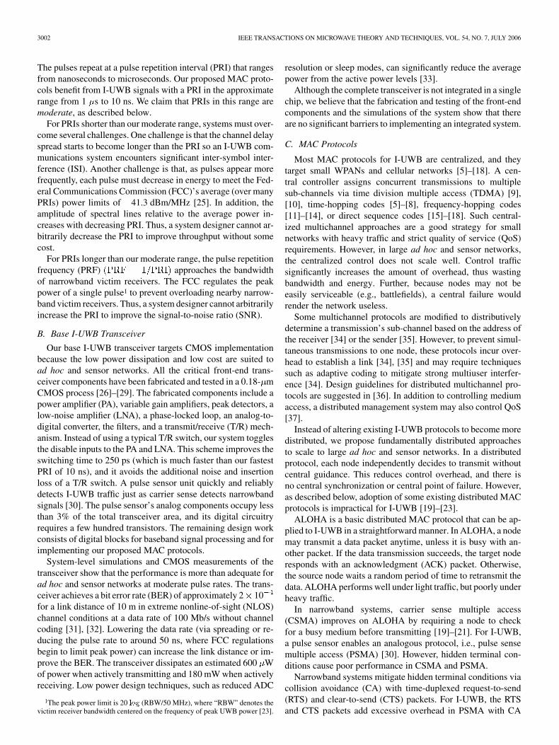
First,weevaluate the throughputofM-ALOHAandM-PSMA.Fig. 8(a) varies the number of number of sub-channels (thenumber of signals that the multiuser receiver in Section III cansimultaneously decode) from to at 1 Mp/s. Inall cases, M-PSMA achieves a higher throughput and is morestable than M-ALOHA. As a multiuser receiver supports moresub-channels, performance improves for both protocols, butreaches a limit around for M-PSMA and forM-ALOHA. This is because it is highly improbable for a nodeunder M-PSMA to receive more than four simultaneous trans-missions. The clear channel assessment (CCA) prevents anynode within range of a transmitter from initiating a transmissionso only hidden nodes may compete for the extra sub-channelsof a multiuser receiver. Thus, adding more than four sub-chan-nels in the multiuser receiver does not improve throughput forM-PSMA in our topologies. In M-ALOHA, nodes do not checkthe medium before transmitting. Thus, its performance reachesa limit at because it is unlikely that a node receives morethan eight simultaneous transmissions. (On average, less than5% of the nodes have more than eight neighbors).
Fig. 8(b) shows that the benefits of M-PSMA and M-ALOHAdiminish as the pulse rate increases. For a clearer comparison
Fig. 8. Throughput for M-PSMA and M-ALOHA.
among pulse rates, the simulations assume that the hardwarescales in proportion to the pulse rate. For example, at 100 Mp/s,the inter-frame times and pulse sense times are 100 times fasterthan at 1 Mp/s. However, the channel delay spread remains thesame, thus, overlap is more probable at higher rates. The sim-ulations consider a single-user receiver with sub-chan-nels for all pulse rates. At 1 Mp/s, the 1000 ns PRI is muchlonger than the rms delay spread, thus, most transmissions fall ingroup . For M-PSMA, the throughput declines rapidly beyond16 Mp/s and reaches a floor by 32 Mp/s. Beyond the throughputfloor, M-PSMA operates similarly to a single-channel narrow-band system, where simultaneous transmissions always overlap.This is because the PRI is on the order of the channel rms delayspread, thus, it is likely that a transmission falls in group or .The throughput of M-ALOHA transitions more gradually, butalso reaches a floor around 32 Mp/s. Further, M-ALOHA be-comes unstable at high offered loads.
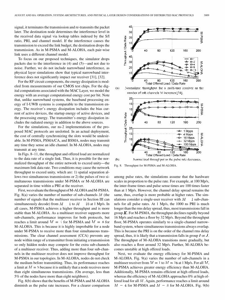
Next, we evaluate the energy efficiency for M-PSMA andM-ALOHA. Fig. 9(a) varies the number of sub-channels in amultiuser receiver from to at 1 Mp/s. For all ,M-PSMA achieves greater energy efficiency than M-ALOHA.Additionally, M-PSMA remains efficient at high offered loads,whereas the efficiency of M-ALOHA approaches 0% at high of-fered load for all . Again, performance reaches a limit around
for M-PSMA and for M-ALOHA. Fig. 9(b)

3010 IEEE TRANSACTIONS ON MICROWAVE THEORY AND TECHNIQUES, VOL. 54, NO. 7, JULY 2006
Fig. 9. Energy efficiency for M-PSMA and M-ALOHA.
shows that the energy efficiency decreases as the pulse rate in-creases because the reduced number of time slots cause morecollisions. For M-PSMA, the energy efficiency starts to decreaserapidly around 16 Mp/s and reaches a floor by 32 Mp/s. The ef-ficiency of M-ALOHA transitions more gradually, but it alsoreaches a floor around 32 Mp/s.
Next, we compare the performance of BSMA, M-PSMA, andM-ALOHA to a baseline distributed PSMA/CA protocol andto a baseline centralized TDMA protocol. Note that the pro-posed techniques in Section IV keep the performance of BSMAroughly independent of pulse rate3 so we simulate at 1 Mp/s fora fair comparison among protocols. The number of sub-chan-nels is , except for TDMA, which has time slots.For TDMA, an omniscient central controller perfectly schedulestime slots for exclusive channel access and spatial multiplexing.In an actual ad hoc network, the centralized control and singlepoint of failure for TDMA is undesirable.
Fig. 10(a) shows that M-PSMA attains an even higherthroughput than centralized TDMA with perfect scheduling.M-PSMA outperforms TDMA, BSMA, and PSMA/CA be-cause it allows sub-channel interleaving; and it outperformsM-ALOHA because it checks for a busy medium before trans-mitting. The random scheduling of BSMA achieves a throughput
3The 2-ns switching time required by (6) does limit the performance ofBSMA, but only for PRIs well below our moderate range. A full switchingcycle limits the maximum pulse rate to 250 Mp/s = 1 pulse=(2� 2 ns)
Fig. 10. Performance comparison of M-PSMA, PSMA/CA, M-ALOHA,BSMA, and TDMA [24].
close to the perfect scheduling of TDMA. BSMA avoids mostcollisions, and it efficiently handles collisions when they dooccur. BSMA outperforms PSMA/CA because the handshakingpackets add overhead. Further, BSMA allows transmissionsunder exposed node conditions, whereas PSMA/CA does not.M-ALOHA performs worse than even PSMA/CA at high offeredloads because the lack of virtual CCA or a pulse sensor resultsin a considerable number of collisions.
Fig. 10(b) compares the energy efficiency of M-PSMA,M-ALOHA, and BSMA to PSMA/CA and TDMA at 1 Mp/s.From the perspective of energy efficiency, the protocols rankmuch differently than from the perspective of throughput.BSMA is the most energy efficient distributed protocol, andit performs nearly as well as centralized TDMA. BSMA out-performs PSMA/CA because the RTS packets may directlycollide with data packets or indirectly cause collisions by in-terfering with control packets. BSMA outperforms M-ALOHAand M-PSMA because neither multichannel protocol has amechanism to detect or avoid collisions. At low offered load,the energy efficiency of M-PSMA follows that of PSMA/CA.At high offered load, M-PSMA attains about half the energyefficiency of PSMA/CA, but it outperforms M-ALOHA be-cause it checks for channel activity before transmitting. Under

AUGUST AND HA: OPERATION, SYSTEM ARCHITECTURES, AND PHYSICAL LAYER DESIGN CONSIDERATIONS OF DISTRIBUTED MAC PROTOCOLS 3011
Fig. 11. Normalized delay for M-PSMA and TDMA [24].
M-ALOHA, most transmissions collide with each other athigh offered load, and the energy efficiency approaches 0%. InFig. 10, M-ALOHA and M-PSMA operate under single-userreceivers so they may drop some transmissions due to a busyreceiver. Note, however, that increasing to still doesnot improve the energy efficiency of M-ALOHA or M-PSMAto that of BSMA.
Ignoring the relatively small propagation time, the averagetransmission delay of a packet is [22], [41]
(10)
where is the offered load, is the throughput at ,is a sub-channel’s proportion of total link bandwidth, is theaverage retransmission delay computed from the simulations,and is the normalized average delay between successiveretransmissions. We compare the delay of a 1-Mp/s M-PSMAsystem to a hypothetical 1-Mp/s TDMA system that can achievethe same throughput at each . We show M-PSMA only be-cause it outperforms M-ALOHA, and BSMA has no advantagein delay over TDMA. Fig. 11 plots the M-PSMA delay withsolid lines and the TDMA delay with dotted lines. TDMA incursa much longer delay than M-PSMA for low offered load (i.e.,when is close to 1). This is because each sub-channel’sbandwidth decreases by a factor of so it takes times longerto transmit a packet on an empty channel. For the proposedM-PSMA MAC, is always one because each successful trans-mission uses the full channel bandwidth.
VI. CONCLUSION
I-UWB is an attractive radio technology for ad hoc and sensornetworks due to its robustness to multipath fading, sub-cen-timeter ranging ability, and low-cost low-power hardware. Wehave proposed three distributed MAC protocols that are customtailored to large ad hoc and sensor networks with I-UWB radios.None of the protocols significantly complicates hardware, addscontrol traffic overhead, or has a central point of failure. Theproposed protocols outperform more general approaches suchas CA or time division.
The two multichannel MAC protocols, i.e., M-PSMA andM-ALOHA, can significantly reduce the probability of col-lision, depending on the PRI and the channel conditions. Incontrast to traditional multichannel MACs and handshakingschemes, M-PSMA and M-ALOHA improve performancewithout reducing link bandwidth, increasing delay, addinghardware complexity, or adding handshaking overhead. Interms of throughput and delay, M-PSMA outperforms all otherprotocols, and it is suitable for distributed networks that requirea high aggregate throughput. A multiuser I-UWB receiver,which can receive several time-interleaved transmissions con-currently, further improves throughput, and it brings the energyefficiency of M-PSMA close to that of PSMA/CA.
The busy-signal protocol, i.e., BSMA, provides superior en-ergy efficiency over other distributed MAC protocols becausesource nodes can assess the status of ongoing data transmis-sions. Hence, BSMA is a suitable protocol for energy-sensi-tive networks. Whereas narrowband systems require two trans-ceivers to implement a busy-signal MAC protocol, our I-UWBsystem requires only one transceiver to save cost, power, andcircuit complexity. Simulations show that our physical layer de-sign techniques result in a busy signal that is easily detectableand that does not interfere with data reception.
REFERENCES
[1] S. Verdu, “Spectral efficiency in the wideband regime,” IEEE Trans.Inf. Theory, vol. 48, no. 6, pp. 1319–1343, Jun. 2002.
[2] L. W. Fullerton, “Reopening the electromagnetic spectrum with ul-trawideband radio for aerospace,” in IEEE Proc. Aerosp. Conf., Mar.2000, vol. 11, pp. 201–210.
[3] M. Nakagawa, H. Zhang, and H. Sato, “Ubiquitous homelinks based onIEEE 1394 and ultra wideband solutions,” IEEE Commun. Mag., vol.41, no. 4, pp. 74–82, Apr. 2003.
[4] D. G. Leeper, “A long-term view of short-range wireless,” Comput.,vol. 34, no. 6, pp. 39–44, Jun. 2001.
[5] F. Cuomo, C. Martello, A. Baiocchi, and F. Capriotti, “Radio re-source sharing for ad hoc networking with UWB,” IEEE J. Sel. AreasCommun., vol. 20, no. 12, pp. 1722–1732, Dec. 2002.
[6] S. S. Kolenchery, J. K. Townsend, and J. A. Freebersyser, “A novelimpulse radio network for tactical military wireless communications,”in IEEE Military Commun. Conf., Oct. 1998, vol. 1, pp. 59–65.
[7] J. Zhang, R. A. Kennedy, and T. D. Abhayapala, “New results on the ca-pacity ofm-ary PPM ultra-wideband systems,” in IEEE Int. Commun.Conf., May 2003, vol. 4, pp. 2867–2871.
[8] M. Z. Win and R. A. Scholtz, “Ultra-wide bandwidth time-hoppingspread-spectrum impulse radio for wireless multiple-access communi-cations,” IEEE Trans. Commun., vol. 48, no. 4, pp. 679–689, Apr. 2000.
[9] 802.15.3-2003 IEEE Standards for Information Technology—Part15.3: Wireless Medium Access Control (MAC) and Physical Layer(PHY) Specifications for High Rate Wireless Personal Area Networks(WPAN), 802.15.3 Draft Standard, Draft P802.15.3/D17, Feb. 2003.
[10] J. P. K. Gilb, Wireless Multimedia: A Guide to the IEEE 802.15.3 Stan-dard. Piscataway, NJ: IEEE Press, 2004.
[11] E. Saberinia and A. H. Tewfik, “Multi-user UWB-OFDM communica-tions,” in IEEE Pacific Rim Commun., Comput., Signal Process. Conf.,Aug. 2003, vol. 1, pp. 127–120.
[12] G. R. Aiello and G. D. Rogerson, “Ultra-wideband wireless systems,”IEEE Micro, vol. 4, no. 2, pp. 36–47, Jun. 2003.
[13] Z. Shiwei, L. Huaping, and S. Mo, “Performance of a multi-band ultra-wideband system over indoor wireless channels,” in 1st IEEE Con-sumer Commun. Networking Conf., Jan. 2004, pp. 700–702.
[14] J. Balakrishnan, A. Batra, and A. Dabak, “A multi-band OFDMsystem for UWB communication,” in Proc. IEEE Ultra WidebandSyst. Technol. Conf., Nov. 2003, pp. 354–358.
[15] N. Boubaker and K. B. Letaief, “Ultra wideband DSSS for multiple ac-cess communications using antipodal signaling,” in IEEE Int. Commun.Conf., May 2003, vol. 3, pp. 2197–2201.
[16] L. Qinghua and L. A. Rusch, “Multiuser detection for DS-CDMAUWB in the home environment,” IEEE J. Sel. Areas Commun., vol.20, no. 12, pp. 1701–1711, Dec. 2002.

3012 IEEE TRANSACTIONS ON MICROWAVE THEORY AND TECHNIQUES, VOL. 54, NO. 7, JULY 2006
[17] P. Runkle, J. McCorkle, T. Miller, and M. Welborn, “DS-CDMA:The modulation technology of choice for UWB communications,”in Proc. IEEE Ultra Wideband Syst. Technol. Conf., Nov. 2003,pp. 364–368.
[18] W. Horie and Y. Sanada, “Novel CSMA scheme for DS-UWB ad hocnetwork with variable spreading factor,” in Joint Workshop Int. UltraWideband Syst. Conf. Ultra Wideband Syst. Technol., May 2004, pp.361–365.
[19] A. Woo and D. E. Culler, “A transmission control scheme for mediaaccess in sensor networks,” in Proc. Int. Mobile Comput. NetworkingConf., Jul. 2001, pp. 221–235.
[20] 802.15.4-2003 IEEE Standard for Information Technology—Part15.4: Wireless Medium Access Control (MAC) and Physical Layer(PHY) specifications for Low Rate Wireless Personal Area Networks(LR-WPANS), IEEE Standard 802.15.4, 2003.
[21] Y. Wei, J. Heidemann, and D. Estrin, “An energy-efficient MAC pro-tocol for wireless sensor networks,” in 21st Annu. Joint IEEE Comput.Commun. Societies Conf., Jun. 2002, vol. 3, pp. 1567–1576.
[22] A. Nasipuri, J. Zhuang, and S. Das, “A multichannel CSMA MAC pro-tocol for multihop wireless networks,” in IEEE Wireless Commun. Net-working Conf., Sep. 1999, vol. 3, pp. 1402–1406.
[23] A. C. V. Gummalla and J. O. Limb, “Design of an access mecha-nism for a high speed distributed wireless LAN,” IEEE J. Sel. AreasCommun., vol. 18, pp. 1740–1750, Sep. 2000.
[24] N. J. August, W. C. Chung, and D. S. Ha, “Distributed MAC protocolsfor UWB ad hoc and sensor networks,” in IEEE Radio Wireless Symp.,Jan. 2006, pp. 511–514.
[25] “FCC revision of part 15 of the Commission’s rules regarding ultra-wideband transmission systems: First report and order,” FCC, Wash-ington, DC, Tech. Rep., Feb. 2002. [Online]. Available: http://hraun-foss.fcc.gov/edocs_public/attachmatch/FCC-02-48A1.pdf
[26] S. Jose, H. J. Lee, D. S. Ha, and S. S. Choi, “A low power CMOS poweramplifier for ultra wideband (UWB) applications,” in Int. Circuits Syst.Symp., May 2005, pp. 5111–5114.
[27] R. Thirugnanam, D. S. Ha, and S. S. Choi, “4-bit 1.4 GS/s low powerfolding ADC for UWB systems,” in IEEE Int. Ultra Wideband Conf.,Sep. 2005, pp. 536–541.
[28] S. Wang, D. S. Ha, and S. S. Choi, “A 6-bit 5.4-Gsamples/s CMOSD/A converter for DS-CDMA UWB transceivers,” in IEEE Int. UltraWideband Conf., Sep. 2005, pp. 333–338.
[29] K. Marsden, H.-J. Lee, D. S. Ha, and H.-S. Lee, “Low powerCMOS re-programmable pulse generator for UWB systems,” inIEEE Ultra Wideband Syst. Technol. Conf., Nov. 2003, pp.443–337.
[30] N. J. August, H. J. Lee, and D. S. Ha, “Design of pulse sensor to de-tect medium activity in UWB networks,” in IEEE Int. Ultra WidebandConf., Sep. 2005, pp. 70–75.
[31] H. J. Lee, D. S. Ha, and H.-S. Lee, “Toward digital UWBradios: Part II—A system design to increase data throughputfor a frequency domain UWB receiver,” in Joint Int. WorkshopUltra Wideband Syst. Conf. Ultra Wideband Syst. Technol., May2004, pp. 253–257.
[32] H. Lee and D. Ha, “A frequency domain approach for all-digitalCMOS ultra wideband receivers,” in IEEE Ultra Wideband Syst.Technol. Conf., Nov. 2003, pp. 86–90.
[33] H.-J. Lee, D. S. Ha, and H.-S. Lee, “Toward digital UWB radios:Part I—Frequency domain UWB receiver with 1 bit ADCs,” in Proc.Joint Int. Workshop Ultra Wideband Syst. Conf. Ultra Wideband Syst.Technol., May 2004, pp. 248–252.
[34] J.-Y. Le Boudec, R. Merz, B. Radunovic, and J. Widmer, “DCC-MAC:A decentralized MAC protocol for 802.15.4a-like UWB mobile ad hocnetworks based on dynamic channel coding,” in Proc. 1st Annu. Broad-band Networks Conf., Oct. 2004, pp. 396–405.
[35] M.-G. Di Benedetto, L. De Nardis, M. Junk, and G. Giancola,“(UWB)2̂: Uncoordinated, wireless, baseborn, medium access con-trol for UWB communication networks,” Mobile Networks Applicat.,3rd quarter, 2005, to be published.
[36] A. El Fawal, J.-Y. Le Boudec, R. Merz, B. Radunovic, J. Widmer, andG. M. Maggio, “Tradeoff analysis of PHY-aware MAC in low-rate,low-power UWB networks,” IEEE Commun. Mag., vol. 43, no. 12, pp.147–155, 2005.
[37] G. Giancola, C. Martello, F. Cuomo, and M.-G. Di Benedetto, “Radioresource management in infrastructure-based and ad hoc UWB net-works,” Wireless Commun. Mobile Comput., vol. 5, no. 5, pp. 581–597,Aug. 2005.
[38] J. Ding, L. Zhao, S. Medidi, and K. Sivalingam, “MAC protocols forultra-wide-band (UWB) wireless networks: Impact and channel acqui-sition time,” in Proc. SPIE ITCOM02, Jul. 2002, pp. 97–106.
[39] J. Foerster, IEEE 802.15 WPANs, “Channel Modeling Subcom-mittee report (final),” Tech. Rep. P802. 15-02/368r5-SG3a, Dec.2000. [Online]. Available: http://grouprt.ieee.org/groups/802/15/pub/2002/Nov02/02490r0P802-15_SG3a-Channel-Modeling-Subcom-mittee-Report-Final.zip.
[40] F. Xue and P. R. Kumar, “The number of neighbors needed for con-nectivity of wireless networks,” ACM Wireless Networks, vol. 10, no.2, pp. 169–181, Mar. 2004.
[41] N. J. August, H.-J. Lee, and D. S. Ha, “An efficient multi-user UWBreceiver for distributed medium access in ad hoc and sensor networks,”in IEEE Radio Wireless Conf., Sep. 2004, pp. 455–458.
[42] F. Tobagi and L. Kleinrock, “Packet switching in radio channels: PartII—The hidden terminal problem in carrier sense multiple-access andthe busy-tone solution,” IEEE Trans. Commun., vol. COMM-23, no.12, pp. 1417–1433, Dec. 1975.
[43] C. Wu and V. Li, “Receiver-initiated busy-tone multiple access inpacket radio networks,” in Proc. ACM Frontiers Comput. Commun.Technol. Workshop, Stowe, VT, Aug. 11–13, 1987, pp. 336–342.
[44] L. W. Fullerton, “Full duplex ultrawide-band communication systemand method,” U.S. Patent 5 687 169, Nov. 11, 1997.
[45] N. J. August and D. S. Ha, “An efficient UWB radio architecture forbusy signal MAC protocols,” in IEEE Sensor and Ad Hoc Commun.Networks Conf., Oct. 2004, pp. 10–10.
Nathaniel J. August (S’03–M’05) was born inCumberland, MD, in 1975. He received the B.S.degree in computer engineering (with a minor incomputer science), M.S. degree in electrical engi-neering, and Ph.D. degree in electrical engineeringfrom the Virginia Polytechnic Institute and StateUniversity, Blacksburg, in 1998, 2001, and 2005,respectively.
From 1995 to 2005, during internships, he wasa Validation Engineer with the Intel Corporation inboth their Folsom, CA and Portland, OR branches.
In April 2006, he joined the Intel Corporation in Portland, OR, as a ComponentDesign Engineer. He has authored ten papers in the field of UWB commu-nication. He coauthored An Introduction to Ultra Wideband CommunicationSystems (Prentice-Hall, 2005). His research interests include low-power verylarge scale integration (VLSI) design, video codecs, signal processing, RFidentification (RFID) systems, and UWB communications systems.
Dong Sam Ha (M’86–SM’97) received the B.S.degree in electrical engineering from Seoul NationalUniversity, Seoul, Korea, in 1974, and the M.S. andPh.D. degrees in electrical and computer engineeringfrom the University of Iowa, Iowa City, in 1984 and1986, respectively.
Since Fall 1986, he has been a faculty memberwith the Department of Electrical and ComputerEngineering, Virginia Polytechnic Institute (VirginaTech) and State University, Blacksburg. He is cur-rently a Professor and Director of the Center for
Embedded Systems and Critical Applications (CESCA). He supervises theVirginia Tech VLSI for Telecommunications (VTVT) Group, which specializesin VLSI design for wireless communications including UWB and wirelesssensor systems for monitoring and diagnosis of buildings and vehicles. Duringa research leave from January to June 2003, he was with Freescale (formerlyXtreme Spectrum), where he was involved in UWB system design andlow-power baseband signal processing. Along with his students, he has devel-oped four computer-aided design (CAD) tools for digital circuit testing and hascreated a standard library of CMOS cells. The library cells and source code forthe four tools have been distributed to over 250 universities and research insti-tutions worldwide. He has authored or coauthored 30 papers in the UWB areaover the past three years. He contributed to An Introduction to Ultra WidebandCommunication Systems (Prentice-Hall, 2005). His research interests includelow-power VLSI design for wireless communications, low-power/high-speedanalog and mixed-signal design, RF integrated-circuit (IC) design, UWBRFIDs, wireless sensor systems for monitoring and diagnosis of buildings andvehicles, and reconfigurable architectures.
Dr. Ha was the general chair of the 2005 System-on-Chip (SOC) Conferenceand a member of the 2005 Technical Program Committee of the InternationalConference on Ultra Wideband (ICU).