Embed Size (px)
Citation preview

IEEE TRANSACTIONS ON ENERGY CONVERSION, VOL. 25, NO. 4, DECEMBER 2010 1187
Fuzzy Fault Diagnosis and Accommodation Systemfor Hybrid Fuel-Cell/Gas-Turbine Power Plant
Wenli Yang, Student Member, IEEE, Kwang Y. Lee, Fellow, IEEE, S. Tobias Junker, and Hossein Ghezel-Ayagh
Abstract—The concept of hybrid fuel-cell power plants hasshown its potential for applications and is already under com-mercialization. In a hybrid fuel-cell and turbine power plant, thecontrol system is an essential component that guarantees reliableand efficient operations. However, due to the limited informationpossessed by particular local controllers, the plant may become de-graded or unstable during system failures. To regulate the powerplants under such abnormal situations, a fault diagnosis and ac-commodation (FDA) system based on fuzzy logic has been devel-oped as an effective complement for the local control scheme. Beinga quantitative approach, the fuzzy FDA system can be implementedwith considerably lower complexities than an analytical fault reg-ulator. The system structures and design methods are discussed inthis paper. Three types of controllers are implemented and investi-gated. Simulation results are presented to verify the performanceof the overall system.
Index Terms—Fault accommodation, fault diagnosis, fuel cells,fuzzy logic, hybrid fuel-cell and turbine power plant.
I. INTRODUCTION
A S AN alternative to fossil fuel generation technologies,fuel-cell system has significant advantages compared to
traditional power plants—noticeably low emissions, high con-version efficiency, quiet operation, flexible siting, and scala-bility. Because of its predominancies, fuel-cell programs havereceived extensive attentions and become a major part of theU.S. distributed generation program [1]. The integration of afuel-cell stack with a gas turbine has become a convincing tech-nology that can greatly enhance the overall efficiency of thepower plant. Based on this hybrid structure, the molten car-bonate fuel-cell (MCFC) and turbine system [under the tradenames: Direct FuelCell/Turbine (DFC/T)] has been developedby FuelCell Energy, Inc., and is expected to approach an effi-ciency of 75%. The DFC/T power plant discussed in this paperconsists of a 250-kW Direct FuelCell [2], where natural gasis internally reformed to produce hydrogen fuel, and a 60-kWCapstone MicroTurbine.
Meanwhile, dynamic modeling and simulation have beenproven to be powerful tools for the study of the transient and
Manuscript received December 30, 2008; revised September 23, 2009; ac-cepted July 5, 2010. Date of publication September 16, 2010; date of currentversion November 19, 2010. This work was supported in part by the U.S.Department of Energy under Grant DE-FG02–02ER86140. Paper no. TEC-00520-2008.
W. Yang is with the Electrical Engineering Department, The PennsylvaniaState University, University Park, PA 16802 USA (e-mail: [email protected]).
K. Y. Lee is with the Department of Electrical & Computer Engineering,Baylor University, Waco, TX 76798 USA (e-mail: [email protected]).
S. T. Junker and H. Ghezel-Ayagh are with the FuelCell Energy, Inc.,Danbury, CT 06813 USA (e-mail: [email protected]; hghezel@fce. com).
Digital Object Identifier 10.1109/TEC.2010.2060341
global behaviors of these direct reforming MCFC systems [3].A fundamental model of the DFC along with the local con-trol and operation strategies were developed in [4] and [5]. Inaddition, the dynamic model provides a platform for investi-gating advanced control algorithms and dynamic optimizationroutines during the design phase. Choi et al. [6] developed aneural network supervisor (NNS) that generates optimal set-points and feedforward control inputs for the DFC/T system.The NNS was trained with the data generated by a large-scalenonlinear trajectory planning method [7]. However, performingwell only during normal operations is insufficient for a powerplant with advanced control technologies. Since local controllersonly have limited information regarding the entire plant, incor-rect control behaviors may be taken due to faults anytime andanywhere. These abnormalities may consequently trigger per-formance degradations or even instabilities. Therefore, whenfaults occur, the control system should be able to detect thefaults at an early stage and react properly to avoid damage ordegradation.
Extensive research and investigations on fault diagnosis andaccommodation (FDA) algorithms have been done in recentdecades by researchers [8]–[19]. Instead of hardware redun-dancy, where redundant physical subsystems are constructed,most of the current research in FDA is based on analyticalredundancy in which sensory measurements are processed ana-lytically to compute the value of a desired variable. Using thismethod, Polycarpou and Helmicki [10] and Farrel et al. [11]provided a framework of the FDA architecture and a generallearning methodology for detecting and regulating system fail-ures. Meanwhile, intelligent control theories are found to bepowerful tools in FDA in recent years. These intelligent ap-proaches mainly include NNs [12], [13], fuzzy systems [14],[15], and neurofuzzy systems [16]. However, most of these ap-proaches assume that the system, either linear or nonlinear, isfully measurable or observable, which is not always true in realengineering problems, especially for large-scale complex plantssuch as the DFC/T plant. Hence, in this paper, a fuzzy FDA sys-tem is introduced with simulation results for various possiblefaulty scenarios.
II. PROCESS DESCRIPTION OF THE DFC/T POWER PLANT
The two major components of the DFC/T system include aninternally reforming MCFC and a gas turbine [20]. The primaryfeature of this structure is a high integration level of fuel cells,gas turbine, and heat exchangers. The system flow diagram ofthe DFC/T is provided in Fig. 1, where gray blocks, single-sided black arrows, and double-sided arrows represent physical
0885-8969/$26.00 © 2010 IEEE

1188 IEEE TRANSACTIONS ON ENERGY CONVERSION, VOL. 25, NO. 4, DECEMBER 2010
Fig. 1. Flow diagram of FuelCell Energy’s DFC/T hybrid system with localcontrollers.
subunits, gas flows, and heat exchangers, respectively. Localcontrollers and control loops are plotted in dotted lines.
The fuel, i.e., methane and water, is introduced to the plantthrough a humidifying heat exchanger (HH), and heated againby a fuel preheater (FP) and a super heater (SH) prior to en-tering the anode of the fuel-cell stack. These heat exchangersprepare the cold fuel with an appropriate temperature for thechemical reactions in the fuel cells and the fuel preconverter,where the fuel is partially reformed into hydrogen and carbondioxide in the presence of catalysts. The chemical reactions canbe represented by the following [3]:
CH4 + H2Oreforming
———−→CO + 3H2 (1)
CO + H2Owater-gas shift
—————−→CO2 + H2 . (2)
Meanwhile, the air is injected to the system by an air com-pressor driven by a gas turbine. The cold air is subsequentlyheated by a low-temperature heat recuperator (LTR), a sec-ondary start-up heater (SSH), and a high-temperature heat re-cuperator (HTR). The compressed air with high temperature isthen expanded in the gas turbine, propelling the air compressorand an ac generator producing extra electric power. The anodeoff-gas containing a portion of unreacted fuel is fully oxidizedby the air in an anode gas oxidizer (AGO), producing extra heatto drive the gas turbine. The oxidized gas finally enters the cath-ode of the fuel-cell stack as a reactant of the electrochemicalreactions shown in the following:
Anode: H2 + CO2−3 → CO2 + H2O + 2e− (3)
Cathode: CO2 +12O2 + 2e− → CO2−
3 . (4)
The cathode off-gas is finally recycled by heat exchangers toheat up the cold fuel and the fresh air. All heaters in the systemare heat exchangers except SSH, which is an electrical heater.
To maintain the process performing smoothly and efficiently,five proportional–integral (PI) controllers are installed in theDFC/T system. A FP controller is used to maintain the temper-ature of the reforming reactions according to the characteristicof the catalyst. Meanwhile, LTR, SSH, AGO, and turbine speedcontrollers are placed, respectively, to regulate cathode inlet
temperature, AGO outlet temperature, and turbine rotationalspeed. The FDA scheme presented in this paper is developedbased on these processes and control structures.
III. FUZZY FAULT DIAGNOSIS
A. Definition of Fuzzy Faults
Power plant faults can occur anywhere in the plant at anytime. However, it is impossible and unnecessary for a controlsystem to identify the exact locations of all minor faults. On theother hand, the ability of locating faults at a subunit level is suffi-cient for control system design. Meanwhile, temperature controlscheme is more complicated and important than other controlschemes, since the temperature exchangers and controllers arethe major balance-of-plant equipments that determine the en-ergy distribution of the entire system and guarantee smooth andreliable operations [20]. The DFC/T power plant is operatingunder constant pressure and only two pressure controllers ex-ist in the system [4]. The fuel mass flow rate does not changealong pipes or heat exchangers. Thus, the faults in pressure ormass/mole flows can be easily determined directly from themeasurement data. However, the temperatures are highly cou-pled throughout the system and make the temperature faults noteasy to diagnosis and isolate.
In this paper, only six fault patterns are defined on temperaturecontrol failures at the six major heat exchangers in the fuzzy faultdiagnosis system. These fault patterns are:
1) HH fault;2) FP fault;3) LTR fault;4) HTR fault;5) AGO fault;6) SSH fault.To provide more information about the temperature failures,
two fault styles are defined for each fault pattern according tofault symptoms.
1) The first style is “P-fault,” which represents the case thatthe actual output temperature of a subunit is higher thanexpected. This is usually caused by the failure of a controlvalve, such that heat will be fully exchanged between twostreams without control.
2) In contrast, the second style is “N-fault,” which representsthe case that actual output temperature of a subunit is lowerthan expected. This is usually caused by the fault positionof a control valve such that heat cannot be transferredbetween two streams.
Although these fault styles are described by the faulty posi-tions of control valves, they can also represent a series of faultshaving similar symptoms, such as failures in sensors, actuators,and other parts of control loops or gas flows. Even though somesubunits such as HH and HTR are not controlled, faults withsimilar symptoms may be caused by other reasons, such as foul-ing, eroding, or electrical problems. Thus, these fault styles arealso applicable for temperature faults in these subunits. Oncethe fault pattern and style are determined by the fuzzy fault di-agnosis system, human operators will use this information toidentify the detailed reason for the fault.

YANG et al.: FUZZY FAULT DIAGNOSIS AND ACCOMMODATION SYSTEM FOR HYBRID FUEL-CELL/GAS-TURBINE POWER PLANT 1189
Fig. 2. Block diagram of the FDA system.
B. Diagnosis Algorithm
The fault-diagnosis algorithm usually includes two steps:residual generation and decision making [8], [13], [17]. The an-alytical redundancy method generates residuals by comparingthe outputs of a plant with a mathematical model, either analyt-ical or numerical [8]. In this paper, the mathematical model ofthe DFC/T in [20] is applied as a reference of normal operationswithout any fault. The outputs of the power plant (power, tem-perature, pressure, etc.) are compared with the estimated outputsof the model. The diversities between the plant and model serveas the residuals used for decision-making.
Since the DFC/T power plant is highly coupled and complex,the model outputs for each subunit are estimated separately. Forthe ith subunit, the output yi is a function of the states xi , theinputs yk of this subunit (or the outputs of the subunits connectedto it), and the control input ui , as shown in (5). Meanwhile,the estimated output yi of the ith subunit is a function of theestimated states xi , and the inputs yk and ui of the actual subunit,as shown in (6). The dynamic equations are defined in the plantmodel [3], [20] and have the same initial conditions as in thereal plant. The residual is thus calculated by (7) as follows:
yi = f (xi, yk , ui) (5)
yi = f (xi , yk , ui) (6)
resi = yi − yi . (7)
When the plant is devoid of faults, the residuals of all subunitswill be small. However, if a fault occurs in the plant, the residualsfor one or several subunits will be noticeable and detectable.
A number of decision-making methodologies have been in-vestigated [10]–[16]. In this study, fuzzy logic is used to deter-mine faulty conditions, because the fuzzy theory is an effectivetool in processing the ambiguous relationships of fuzzy faultsdue to the limited information of the system. The structure of thefault diagnosis system is shown in Fig. 2. While the residual onlyreflects the state of the plant at a particular time instant, its inte-gral contains much more information about the time history [21]of plant status, which is more important for fault diagnosis thanonly the residual. For instance, small and persistent residualswill be accumulated by integration and become noticeable. Incontrast, a brief disturbance may have a much smaller weightin decision-making. Therefore, the integral of the residual be-tween the actual plant and the nominal model is assigned as theprimary input of the FDA system.
Moreover, the integrals are unable to provide sufficient in-formation about faults, since either a large residual or a smallresidual can be accumulated to the same integral values as timeelapses. However, the causes of the residuals may be completelydifferent. The small residual could be caused by the inaccuracyof the model but not the system fault, and false alarm might betrigged, if monitoring only the integrals. Hence, the values ofresiduals for each subunit are used by the diagnosis system asthe secondary input variable in determining the causes for thedisturbances.
C. Selection of Variables
According to the algorithm indicated in Fig. 2, the variable yi
and the corresponding estimated variable yi should be selectedfrom all process variables for each subunit, on which the faultpatterns are defined. The variables need to possess the ability ofpresenting the fundamental operational status of the subunits,and must be easily measured or calculated from the actual plantso that the diagnosis can be made practical.
In this paper, the diagnosis system will be focused on the fail-ures of temperature control, where the fault patterns are definedon heaters or heat exchangers. The energy increase of a streamfrom inlet to outlet at the cold side of a heat exchanger is a primecandidate that represents the amount of heat transferred by theheat exchanger and indicates the working status of the subunit.The energy increase can be calculated as follows:
yi = ΔEi = N outi Hout
i − N ini H in
i (8)
Hi =7∑
k=1
x(k)i
(AkTi + BkT 2
i + CkT 3i + DkT 4
i
)(9)
where Nout/ ini and H
out/ ini are the outlet/inlet mole flow rate
and mole enthalpy of the ith subunit, respectively. The moleflow rate can either be measured from the actual plant, or beestimated by the mathematical model. The mole enthalpy ofthe gas mixture can be obtained from (9), where x
(k)i is the
mole fraction of the kth component of the gas mixture, which isnot measurable but can be approximated by the plant model; Ti
is the measured temperature of a particular gas flow; Ak , Bk , Ck ,and Dk are the coefficients obtained from the integration of thespecific heat capacity of the kth element of the gas mixture [3].The reference variable ΔEi is calculated similarly, but usingthe simulated variables from the model
yi = ΔEi = N outi Hout
i − N ini H in
i (10)
Hi =7∑
k=1
x(k)i
(Ak Ti + BkT 2
i + Ck T 3i + DkT 4
i
). (11)
Taking the HTR as an example, the variable ΔEHTR is theenergy transfer rate of the HTR based on measurements andrepresents its operational status. The reference ΔEHTR is cal-culated from the mathematical model. The residual for HTRfault diagnosis is the difference between ΔEHTR and ΔEHTR
resHTR = ΔEHTR − ΔEHTR . (12)

1190 IEEE TRANSACTIONS ON ENERGY CONVERSION, VOL. 25, NO. 4, DECEMBER 2010
Fig. 3. Fuzzy membership functions for fuzzy fault diagnosis.
D. Membership Functions and Fuzzy Rules
Three membership functions for fuzzy sets, i.e., positive (P),negative (N), and zero (Z) in Fig. 3, are defined for P-fault,N-fault, and fault-free status, respectively. The likelihood of theexistence of a fault is expressed by the membership values that itbelongs to a particular fuzzy set. Because of the nature of faultsand the limited information about failures, there does not existclear boundaries distinguishing the different faulty situations.Thus, the overlapping membership functions are useful toolsin expressing such fuzzy relationships. Meanwhile, the primaryand secondary inputs are represented in terms of fuzzy logicby the membership functions in Fig. 3. These functions mapthe normalized input variables to the membership values, whichwill be processed by fuzzy rules.
After the inputs are converted into the membership values,the fuzzy rules will be launched to compute the likelihood ofa fault belonging to different fuzzy sets. Three major rules aredefined for each fault pattern as follows:
1) if {∫
res(ΔEi)} is zero, then no fault exists;2) if {
∫res(ΔEi)} is positive and {res(ΔEi)} is positive,
then “P-fault” exists;3) if {
∫res(ΔEi)} is negative and {res(ΔEi)} is negative,
then “N-fault” exists.Here, ΔEi is the input variable for the ith subunit and res
indicates the residual of the variable. As in the first rule, if theintegral is zero, nonfault situation can be determined based onthe previous analysis. The second rule defines the conditionfor the “P-fault,” where the temperature difference is signifi-cantly higher than expected. The third rule defines the conditionfor the “N-fault” that the temperature difference is negative,which indicates heat cannot be transferred through the heatexchanger.
Finally, for convenience, the membership values for eachfuzzy set are defuzzified to a scalar value, likelihood in-dex, indicating the likelihood of each fault style. A positivevalue indicates a “P-fault,” while a negative value suggests an“N-fault.” The higher the absolute value is, the more likely thatthe particular fault style happens. Thus, a 6 × 1 vector can beobtained as the diagnosis result, suggesting the existence of thesix defined fault patterns.
IV. FUZZY FAULT ACCOMMODATION
Detecting faults alone is not sufficient, though it is necessaryfor an intelligent control system. When a fault occurs, the plantneeds to be regulated to prevent from entering critical or evenunstable operating regions before the fault is cleared or humantakes over the control system. Due to the high complexity of theDFC/T power plant and the random nature of faults, it is difficultto design specific and detailed regulators to accommodate thesystem with very limited information on the causes and conse-quences of the faults. Nevertheless, fuzzy logic, as a qualitativescenario, is a powerful tool that has low complexity and lessdifficulty in designing the fault-accommodation system.
A. Accommodation Strategies
The core of the DFC/T power plant is the fuel-cell stack,where chemical potential is converted into electric power. Thus,maintaining the electrochemical reactions smooth and stable isthe primary goal of the control system, either under normalsituations or during system failures. To achieve this goal, thetemperature of the fuel-cell stack should be maintained within acertain range determined by the characteristics of the catalystsand the operating conditions. After the temperature is regulated,the power plant needs to track the assigned power load demand.Therefore, the objective of the accommodation system is toregulate the temperature of the fuel-cell stack and to recover theoutput power during system failures.
Under normal operations, the stack temperature is dominatedby the cathode inlet temperature TCI , which is controlled by theLTR and SSH controllers on the basis of the setpoints TCISP .The stack power is controlled by the methane flow rate NCH4and the stack current density I2 . The unreacted methane is thenburned in the AGO, and the excessive heat is used by the turbineto generate additional power [5], [20]. However, during systemfailures, the temperature and power control schemes may be-come weak, not functional, or even broken. On the other hand,from the viewpoint of the overall power plant, the stack temper-ature is determined by the energy contained in the methane thatsupplied to the system. Meanwhile, the cold air takes heat offthe plant and transfers the excessive heat to the gas turbine forpower generation. Thus, even though the local control schememay not be fully functional, the stack temperature still can bemaintained by adjusting the amount of the fuel and the amountof the fresh air. The output power can be regulated by adjustingthe stack current density.
Therefore, the control strategies can be described as follows:1) if the stack temperature is higher/lower than normal, then
decrease/increase the fuel flow rate NCH4 and introducemore/less air by increasing/decreasing the compressorspeed RRPM ;
2) if the output power is higher/lower than demand, thendecrease/increase the current density I2 of the stack.
However, all strategies should be executed within the oper-ating regions of the DFC/T power plant. The ratios of fuel-to-current and fuel-to-air need to be maintained within a certainrange to satisfy the requirements of chemical reactions; other-wise, the plant may become unstable or damaged. Moreover,

YANG et al.: FUZZY FAULT DIAGNOSIS AND ACCOMMODATION SYSTEM FOR HYBRID FUEL-CELL/GAS-TURBINE POWER PLANT 1191
Fig. 4. Block diagram of the fault-accommodation system.
the strategies are built based on an assumption that the DFC/Tpower plant is connected to a utility grid so that the power dis-turbance caused by faults and accommodating actions can becompensated.
B. Accommodation Structure
According to the compensation strategies, the control schemein Fig. 4 is implemented in the FDA system. The input signalsare the residuals of the two variables that need to be regulated,i.e., the stack temperature Tstk and the net output power Pnet ofthe plant. Both the residuals and their integrals are introducedto the fault-accommodation controller for the same reason as inthe diagnosis system. The outputs of the controller are setpointsmodifications, which will compensate the original setpoints totake effect. The modified setpoints are restricted to the opera-tional limitations to prevent instability and damages.
C. Controller Design and Tuning
Since the inputs of the fault regulator are the residuals (errors)and their integrals, it is a PI-type controller that can be tunedby a number of classic PID tuning methods [22], [23]. In thisresearch, the membership functions of the fuzzy controller aretriangle functions evenly placed in the interval of [−1, 1]. Todetermine the gains of proportional and integral controls, theactual system is approximated as a first-order plus time-delaysystem, and the minimum integral of time-weighted square error(ITSE) controller tuning rules [22] are applied to optimize theaccommodation controller. Due to the random nature of faults,the dynamic of the postfailure system is hard to determine inreal-time. Thus, the fault controller is tuned according to theaverage parameters of the normal system from half-load modeto full-load mode. For example, the step responses of the stacktemperature of the healthy system are plotted in Fig. 5, wherea step of the methane flow rate NCH4 at 0.05 mol/s is injectedat t = 0 s. Because of the nonlinearity of the DFC/T plant, thetemperature responses are not identical under different powerload profiles. Hence, the average time delay, time constant, andgain are used for controller tuning.
Although the fuzzy accommodation controller is tuned withthe PID tuning method, it is different from the traditional PI con-troller. With the membership functions and fuzzy rules describedin Section IV-A, the fuzzy logic is able to realize nonlinear re-lationship between the proportional and integral controls, rather
Fig. 5. Step response of fuel-cell stack temperature.
Fig. 6. Structure of the fuzzy NN controller.
than the simple aggregation for PI controller. This nonlinearrelationship may achieve faster response and lower overshoot.
D. Fuzzy NNs
Another intelligent system approach for fault regulation is thefuzzy NNs, which possess the learning ability while regulatingthe system [16], [24]. The fuzzy NNs method is also investigatedin this paper and compared with other approaches.
A classic structure of the five-layer NN, as shown in Fig. 6,is used for fault accommodation. The first layer maps the inputsto the membership values for each fuzzy set by the membershipfunctions defined in the previous section. The second layer per-forms the fuzzy “and” operation with multiplication. The thirdlayer is the normalization layer, which normalizes the weightof each rule by the sum of the weights of all rules. The forthlayer is the consequent layer that calculates the implication fromthe decision wi for each rule. The final layer is the aggregationlayer, adding the implications of each rule to a scalar, whichis the output of the fuzzy-neural controller [16]. In the trainingalgorithm, the decisions wi (i = 1, . . . , 9) are the parametersneed to be optimized. The objective function is defined on theITSE index as
E =∫ t
o
τ[res(Tstk)2 + res(Pnet)2] dτ. (13)
1192 IEEE TRANSACTIONS ON ENERGY CONVERSION, VOL. 25, NO. 4, DECEMBER 2010
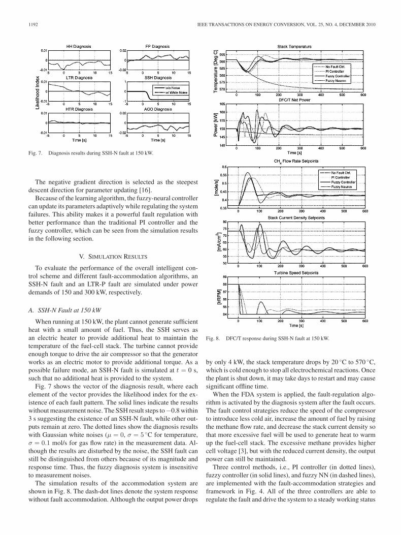
Fig. 7. Diagnosis results during SSH-N fault at 150 kW.
The negative gradient direction is selected as the steepestdescent direction for parameter updating [16].
Because of the learning algorithm, the fuzzy-neural controllercan update its parameters adaptively while regulating the systemfailures. This ability makes it a powerful fault regulation withbetter performance than the traditional PI controller and thefuzzy controller, which can be seen from the simulation resultsin the following section.
V. SIMULATION RESULTS
To evaluate the performance of the overall intelligent con-trol scheme and different fault-accommodation algorithms, anSSH-N fault and an LTR-P fault are simulated under powerdemands of 150 and 300 kW, respectively.
A. SSH-N Fault at 150 kW
When running at 150 kW, the plant cannot generate sufficientheat with a small amount of fuel. Thus, the SSH serves asan electric heater to provide additional heat to maintain thetemperature of the fuel-cell stack. The turbine cannot provideenough torque to drive the air compressor so that the generatorworks as an electric motor to provide additional torque. As apossible failure mode, an SSH-N fault is simulated at t = 0 s,such that no additional heat is provided to the system.
Fig. 7 shows the vector of the diagnosis result, where eachelement of the vector provides the likelihood index for the ex-istence of each fault pattern. The solid lines indicate the resultswithout measurement noise. The SSH result steps to−0.8 within3 s suggesting the existence of an SSH-N fault, while other out-puts remain at zero. The dotted lines show the diagnosis resultswith Gaussian white noises (μ = 0, σ = 5 ◦C for temperature,σ = 0.1 mol/s for gas flow rate) in the measurement data. Al-though the results are disturbed by the noise, the SSH fault canstill be distinguished from others because of its magnitude andresponse time. Thus, the fuzzy diagnosis system is insensitiveto measurement noises.
The simulation results of the accommodation system areshown in Fig. 8. The dash-dot lines denote the system responsewithout fault accommodation. Although the output power drops
Fig. 8. DFC/T response during SSH-N fault at 150 kW.
by only 4 kW, the stack temperature drops by 20 ◦C to 570 ◦C,which is cold enough to stop all electrochemical reactions. Oncethe plant is shut down, it may take days to restart and may causesignificant offline time.
When the FDA system is applied, the fault-regulation algo-rithm is activated by the diagnosis system after the fault occurs.The fault control strategies reduce the speed of the compressorto introduce less cold air, increase the amount of fuel by raisingthe methane flow rate, and decrease the stack current density sothat more excessive fuel will be used to generate heat to warmup the fuel-cell stack. The excessive methane provides highercell voltage [3], but with the reduced current density, the outputpower can still be maintained.
Three control methods, i.e., PI controller (in dotted lines),fuzzy controller (in solid lines), and fuzzy NN (in dashed lines),are implemented with the fault-accommodation strategies andframework in Fig. 4. All of the three controllers are able toregulate the fault and drive the system to a steady working status

YANG et al.: FUZZY FAULT DIAGNOSIS AND ACCOMMODATION SYSTEM FOR HYBRID FUEL-CELL/GAS-TURBINE POWER PLANT 1193
Fig. 9. Diagnosis results during LTR-P fault at 300 kW.
in 300 s with a maximum temperature drop of 10 ◦C. The fuzzycontroller has less overshoot and the fuzzy NN is faster thanthe traditional PI controller in regulating the stack temperature.The three controllers have comparable disturbances of 10 kWin power control, but the fuzzy controller has slightly moreoscillations as time elapses.
B. LTR-P Fault at 300 kW
An LTR-P fault at t = 0 s is simulated in Figs. 9 and 10. Whenthe DFC/T plant is running at an output power of 300 kW, theLTR fails in a faulty position so that heat is fully transferredwithout control. Thus, the compressed air is overheated by theLTR, and finally heats up the fuel-cell stack. Without the fault-accommodation system (see dash-dot lines in Fig. 10), the stacktemperature will rise up to 635 ◦C, which is the upper limit ofthe safe operational region, and may consequently damage thedevice or the catalyst.
The diagnosis results in Fig. 9 present the likelihood indexfor each fault pattern, where the LTR-P fault can be identifiedfrom others by its magnitude and response time, either withoutmeasurement noises, or with the similar Gaussian white noisesas in the previous case.
Once the accommodation system is activated, it increases thecompressor speed to blow more air into the system, decreases theamount of fuel by reducing the methane flow rate, and slightlyincreases the current density to compensate the power drop.However, the plant cannot recover to its previous output powerdue to the reduced amount of fuel and the ratio limitation be-tween current density and methane flow rate.
The three controllers are investigated with the LTR-P fault.In Fig. 10, the controllers are able to regulate the fault and drivethe system to a stable working status in 300 s with a temperaturedisturbance of 10 ◦C and a lower output power of 290 kW, whichis 3.3% less than the demand power. The fuzzy and fuzzy-neuralcontrollers have smaller temperature disturbance than the PIcontroller, but the fuzzy controller converges slower than theothers. For the power control, the fuzzy controller gives lessovershoot but lower convergence speed.
Fig. 10. DFC/T response during LTR-P fault at 300 kW.
VI. CONCLUSION
From the control point of view for the DFC/T plant, the FDAsystem is a necessary complement for the local control scheme,which has only limited authority of the whole system, suchthat the local controllers cannot regulate the system effectivelyduring system failures. However, due to the complexity of theDFC/T system and the random nature of faults, designing an-alytical and detailed fault controllers is extremely difficult. Incontrast, the fuzzy logic proves to be a powerful yet simple toolto achieve the FDA system for the DFC/T power plant.
The diagnosis algorithm based on fuzzy logic is implementedfor the six types of temperature faults and gives out the vector oflikelihood index for the six fault patterns. The diagnosis systemcan identify the fault correctly and promptly, and is insensi-tive to measurement noises. The fault regulation strategies andframework are developed for the fault-accommodation system,where three control methods are implemented and investigated.The simulation results demonstrate that all the three types of

1194 IEEE TRANSACTIONS ON ENERGY CONVERSION, VOL. 25, NO. 4, DECEMBER 2010
controllers are capable with the fault-accommodation frame-work, and can efficiently prevent the DFC/T power plant fromdegradation or damage during system failures.
REFERENCES
[1] M. C. Williams, J. P. Strakey, and S. C. Singhal, “U.S. distributed gener-ation fuel cell program,” J. Power Sources, vol. 131, pp. 79–85, 2004.
[2] H. Ghezel-Ayagh, J. M. Daly, and Z. Wang, “Advances in direct fu-elfell/gas turbine power plants,” in Proc. ASME Turbo Expo, 2003,pp. 625–629.
[3] M. D. Lukas, K. Y. Lee, and H. Ghezel-Ayagh, “Development of a stacksimulation model for control study on direct reforming molten carbonatefuel cell power plant,” IEEE Trans. Energy Convers., vol. 14, no. 4,pp. 1651–1657, Dec. 1999.
[4] M. D. Lukas, K. Y. Lee, and H. Ghezel-Ayagh, “Plant-wide simulation ofdirect reforming molten carbonate fuel cell systems,” in Proc. IEEE PESSummer Meet., 1999, vol. 1, pp. 532–535.
[5] M. D. Lukas, K. Y. Lee, and H. Ghezel-Ayagh, “Operation and control ofdirect reforming fuel cell power plant,” in Proc. IEEE PES Winter Meet.,2000, vol. 1, pp. 523–527.
[6] T.-I. Choi, K. Y. Lee, S. T. Junker, and H. Ghezel-Ayagh, “Neural networksupervisor for hybrid fuel cell/gas turbine power plants,” in Proc. IEEEPES Gen. Meet., 2007, pp. 1–8.
[7] S. Kameswaran, L. T. Biegler, S. T. Junker, and H. Ghezel-Ayagh, “Op-timal off-line trajectory planning of hybrid fuel cell/gas turbine powerplants,” AIChE J., vol. 53, pp. 460–474, Feb. 2007.
[8] J. Calado, J. Korbicz, K. Patan, R. Patton, and J. S. D. Costa, “Softcomputing approaches to fault diagnosis for dynamic systems: A survey,”Eur. J. Control, vol. 7, pp. 248–286, Jul. 2001.
[9] R. Isermann and P. Balle, “Trends in the application of model-based faultdetection and diagnosis of technical processes,” Control Eng. Pract.,vol. 5, pp. 709–719, Mar. 1997.
[10] M. M. Polycarpou and A. J. Helmicki, “Automated fault detection andaccommodation: A learning systems approach,” IEEE Trans. Syst., Man,Cybern., vol. 25, no. 1, pp. 1447–1458, Nov. 1995.
[11] J. Farrel, T. Berger, and B. D. Appleby, “Using learning techniques toaccommodate unanticipated faults,” IEEE Control Syst. Mag., vol. 13,no. 3, pp. 40–49, Jun. 1993.
[12] S. Simani and C. Fantuzzi, “Fault diagnosis in power plant using neuralnetworks,” Info. Sci., vol. 127, pp. 125–136, Aug. 2000.
[13] K. Kim and E. B. Bartlett, “Nuclear power plant fault diagnosis usingneural networks with error estimation by series association,” IEEE Trans.Nucl. Sci., vol. 43, no. 4, pp. 2373–2388, Aug. 1996.
[14] A. L. Dexter, “Fuzzy model based fault diagnosis,” Proc. Inst. Elect.Eng.— Control Theory Appl., vol. 142, no. 6, pp. 545–550, Nov. 1995.
[15] C.-W. Xu and Y.-Z. Lu, “Fuzzy model identification and self-learningfor dynamic systems,” IEEE Trans. Syst., Man, Cybern., vol. 17, no. 4,pp. 683–689, Jul. 1987.
[16] O. M. Al-Jarrah and M. Al-Rousan, “Fault detection and accommodationin dynamic systems using adaptive neurofuzzy systems,” Proc. Inst. Elect.Eng.—Control Theory Appl., vol. 148, no. 4, pp. 283–290, Jul. 2001.
[17] T. Escobet, D. Deroldi, S. D. Lira, V. Puig, J. Quevedo, J. Riera, andM. Serra, “Model-based fault diagnosis in PEM fuel cell systems,” J.Power Sources, vol. 192, pp. 216–223, 2009.
[18] P. M. Frank, “Fault diagnosis in dynamic systems using analytical andknowledge-based redundancy,” Automatica, vol. 26, pp. 459–474, 1990.
[19] H. Monsef, A. M. Ranjbar, and S. Jadid, “Fuzzy rule-based expert systemfor power system fault diagnosis,” Proc. Inst. Elect. Eng.—Gen., Trans.Distrib., vol. 144, no. 2, pp. 186–192, Mar. 1997.
[20] H. Ghezel-Ayagh, M. D. Lukas, and S. T. Junker, “Dynamic modeling andsimulation of a hybrid fuel cell/gas turbine power plant for control systemdevelopment,” in Proc. ASME 2nd Inter. Conf. Fuel Cell Sci., Eng. andTech., 2004, pp. 325–329.
[21] A. Ben-Abdennour and K. Y. Lee, “An autonomous control system forboiler-turbine units,” IEEE Trans. Energy Convers., vol. 11, no. 2,pp. 401–406, Jun. 1996.
[22] A. O’Dwyer, Handbook of PI and PID controller tuning rules, 2nd ed.London, U.K.: Imperial College Press, 2006, ch. 4.
[23] J.-X. Xu, C. Liu, and C. C. Hang, “Tuning of fuzzy PI controllers basedon gain/phase margin specifications and ITAE index,” ISA Trans., vol. 35,pp. 79–91, 1996.
[24] J.-S. R. Jang, “ANFIS: Adaptive-network-based fuzzy inference system,”IEEE Trans. Syst., Man, Cybern., vol. 23, no. 3, pp. 665–685, May/Jun.1993.
Wenli Yang (S’09) received the B.Eng. degree in au-tomation, and the M.Sc. degree in automatic controlfrom Tsinghua University, Beijing, China, in 2004and 2006, respectively, and the Ph.D. degree in elec-trical engineering from the Pennsylvania State Uni-versity, University Park, in 2009.
His research interests include control systems andelectronics, power systems, distributed generation,and artificial intelligence.
Kwang Y. Lee (F’01) received the B.S. degree inelectrical engineering from Seoul National Univer-sity, Seoul, Korea, in 1964, the M.S. degree in electri-cal engineering from North Dakota State University,Fargo, in 1968, and the Ph.D. degree in system sci-ence from Michigan State University, East Lansing,in 1971.
He had been with Michigan State University,Oregon State University, the University of Houston,and the Pennsylvania State University. He is currentlya Professor and Chair of electrical and computer en-
gineering in Baylor University, Waco, TX. His interests include power systemcontrol, operation, planning, and intelligent system applications to power sys-tems and power plant control.
Dr. Lee was an Associate Editor of the IEEE TRANSACTIONS ON NEURAL
NETWORKS, and is currently an Editor of the IEEE TRANSACTIONS ON ENERGY
CONVERSION.
S. Tobias Junker received the Diploma and Ph.D. de-grees in chemical engineering, respectively, from theAachen Institute of Technology, Aachen, Germany,in 1998, and the University of Delaware, Newark, in2004.
He is currently engaged at FuelCell Energy, Inc.,Danbury, CT, where he is involved in the research onadvanced process control concepts for Direct Fuel-Cell/Turbine (DFC/T) and solid oxide fuel-cell tur-bine (SOFC/T) power plants. He is also involved inthe development of detailed dynamic process models
of fuel cells and associated processing equipment, and is developing controlstrategies for DFC/T and SOFC/T power plants.
Hossein Ghezel-Ayagh received the B.S. degreefrom the Abadan Institute of Technology, Abadan,Iran, in 1971, and the M.S. and Ph.D. degrees fromthe Illinois Institute of Technology, respectively, in1977 and 1981, all three in chemical engineering.
He is currently the Project Manager for the de-velopment of Direct FuelCell/Turbine Power Plantunder a Vision 21 Cooperative Agreement with theDepartment of energy. He has been involved in theresearch on fuel cell development, process design andsimulation at FuelCell Energy, Inc., Danbury, CT. He
has also been engaged in evaluation, testing, and design of power plant systemsusing various types of fuels.