Embed Size (px)
Citation preview
IEEE TRANSACTIONS ON COMMUNICATIONS 1
Generalized Frequency Division Multiplexingfor 5th Generation Cellular Networks
Nicola Michailow∗, Maximilian Matthé∗, Ivan Simões Gaspar∗, Ainoa Navarro Caldevilla∗, Luciano Leonel Mendes†∗,Andreas Festag∗ and Gerhard Fettweis∗
∗Vodafone Chair Mobile Communication Systems, Technische Universität Dresden, Germany†Instituto Nacional de Telecomunicações, Sta. Rita do Sapucai, MG, Brazil
Abstract—Cellular systems of the fourth generation (4G) havebeen optimized to provide high data rates and reliable coverageto mobile users. Cellular systems of the next generation will facemore diverse application requirements: the demand for higherdata rates exceeds 4G capabilities; battery-driven communicationsensors need ultra-low power consumption; control applicationsrequire very short response times. We envision a unified physicallayer waveform, referred to as Generalized Frequency DivisionMultiplexing (GFDM), to address these requirements. In thispaper we analyze main characteristics of the proposed waveformand highlight relevant features. After introducing the pri nciplesof GFDM, this paper contributes to the following areas: (i)means for engineering the waveform’s spectral properties,(ii)analytical analysis of symbol error performance over differentchannel models, (iii) concepts for MIMO-GFDM to achievediversity, (iv) preamble-based synchronization that preservesthe excellent spectral properties of the waveform, (v) bit errorrate performance for channel coded GFDM transmission usingiterative receivers, (vi) relevant application scenariosand suitableGFDM parameterizations, (vii) GFDM proof-of-concept and im-plementation aspects of the prototype using hardware platformsavailable today. In summary, the flexible nature of GFDM makesthis waveform a suitable candidate for future 5G networks.
Index Terms—5G scenarios, physical layer, non-orthogonalwaveform, GFDM, pulse shaping, MIMO, synchronization, proof-of-concept.
I. I NTRODUCTION
M OBILE communication has become an essential toolfor the modern society. The first generation of cellular
systems provided basic, yet innovative, voice transmission.Communication started to become personal rather than be-ing connected to fixed locations. The second generation hasdigitalized the voice in order to increase system capacity,battery life of devices and Quality of Service (QoS). It alsointroduced the Short Message Service, which revolutionizedthe way people communicate. The third generation enabledmobile Internet access and data rates not too far behindof wired solutions of that time. The advent of smartphoneswith large storage and processing capabilities equipped withhigh definition screen and cameras, in combination with so-cial networks that turned users from media consumers into
The authors want to thank National Instruments for their generous supportin making the implementation happen.
The support by Vodafone Group R&D helped create the results,anddiscussions shaped our ideas.
This work has been performed in the framework of the FP7 project ICT-318555 "5GNOW", which is partly funded by the European Union.
The authors would like to thank Instituto Nacional de Telecomunicações(Inatel) and Conselho Nacional de Desenvolvimento Científico e Tecnológico(CNPq Brasil) for partially funding the work presented in this paper.
content providers, has pushed the fourth generation towardseven higher throughput. Starting with the second generation,the evolution of the mobile communication has focused onincreasing the throughput.
However, the scenarios foreseen for future fifth generation(5G) networks have requirements that clearly go beyond higherdata rates [1], [2]. The main scenarios for 5G networks aremachine type communication(MTC) [3], Tactile Internet[4]andWireless Regional Area Network(WRAN) [5], while clas-sical bitpipe communication is still considered an importantapplication.
At present, Orthogonal Frequency Division Multiplexing(OFDM) [6] is a widely adopted solution mainly becauseof its robustness against multipath channels [7] and easyimplementation based on Fast Fourier Transform (FFT) al-gorithms [8]. But the application scenarios predicted for 5Gnetworks present challenges which OFDM can only addressin a limited way. MTC and machine-to-machine (M2M) com-munication [9] require low power consumption, which makesthe strict synchronization process required to keep the orthog-onality between subcarriers unaffordable [2]. The low latencyrequired for Tactile Internet and vehicle-to-vehicle (V2V) [10]applications demands for short bursts of data, meaning thatOFDM signals with one cyclic prefix (CP) per symbol wouldpresent a prohibitive low spectral efficiency. The low spectrumefficiency due to the CP insertion is also a problem for WRANapplication, where the typical channel impulse response hasa duration of tenths of microseconds [11]. Additionally, thehigh out-of-band (OOB) emission of OFDM [12] poses achallenge for opportunistic and dynamic spectrum access [13].All these challenges make OFDM not the most promisingwaveform for the next generation networks. In this context,alternative multicarrier schemes are currently being evaluatedas candidates for the PHY layer of next generation of mobilecommunication systems.
In Filter Bank Multicarrier (FBMC) [14], one of the mostinvestigated filtered multicarrier systems, the subcarriers arepulse shaped individually in order to reduce the OOB emis-sions. Because the subcarriers have narrow bandwidth, thelength of the transmit filter impulse response is usually long.Typically, the filter has four times the length of the symbols.As a consequence, FBMC can only achieve good spectralefficiency if the number of transmit symbols is large. Clearly,this solution is not suitable for low latency scenarios, wherehigh efficiency must be achieved with short burst transmis-sions. Universal Filtered Multicarrier (UFMC) [15] is a recent

2 IEEE TRANSACTIONS ON COMMUNICATIONS
binary
sourceencoder mapper GFDM
modulator
A
cyclic
prefixwireless
channel
H̃, ~̃w
synch.remove
prefixequalizer
H−1
GFDM
demodulator
B
demapperdecoderbinary
sink
~b ~bc ~d ~x ~̃x ~̃y
~̃ys~y~z~̂d
~̂bc
~̂b
Fig. 1: Block diagram of the transceiver.
proposal where a group of subcarrier is filtered to reduce theOOB emission. Because the bandwidth of the filter coversseveral subcarriers, its impulse response can be short, whichmeans that high spectral efficiency can be reached in shortburst transmissions. UFMC does not require a CP and it ispossible to design the filters in order to obtain a total blocklength equivalent to the CP-OFDM. However, because thereis no CP, UFMC is more sensitive to small time misalignmentthan CP-OFDM [15]. Hence, UFMC might not be suitable forapplications that require loose time synchronization in order tosave energy. Bi-orthogonal Frequency Division Multiplexing(BFDM) [16] employs well localized pulse shapes at thetransmitter and receiver side that are bi-orthogonal to eachother. The good frequency-localization of the transmit pulsemakes the system robust against frequency dispersion (Dopplereffect) while the good time-localization of the pulse pro-vides robustness against time dispersion (multipath). Neverthe-less, the Balian-Low theorem prohibits time-frequency well-localized pulses when using standard Quadrature AmplitudeModulation (QAM) with maximum spectral efficiency [17].Therefore, BFDM employs Offset QAM (OQAM) to achievewell localized pulses both in time and frequency domains.Hence, critically dense BFDM cannot be easily integratedwith MIMO aiming diversity [18], which is one of the keypoints for 5G applications. Also, similar to FBMC, BFDMneeds to handle long pulse tails that reduces the efficiency forshort burst transmission necessary in low latency and M2Mapplications.
A flexible multicarrier modulation scheme, named Gener-alized Frequency Division Multiplexing (GFDM) [19], hasalso been proposed for the air interface of 5G networks.The flexibility of GFDM allows it to cover CP-OFDM andsingle-carrier frequency domain equalization (SC-FDE) [20]as special cases. GFDM is based on the modulation ofindependent blocks, where each block consist of a numberof subcarriers and subsymbols. The subcarriers are filteredwith a prototype filter that is circularly shifted in time andfrequency domain. This process reduces the OOB emissions,making fragmented spectrum and dynamic spectrum allocationfeasible without severe interference in incumbent servicesor other users. The subcarrier filtering can result in non-orthogonal subcarriers and both inter-symbol interference (ISI)and inter-carrier interference (ICI) might arise. Nevertheless,efficient receiving techniques can eliminate this interference,i.e. a matched filter receiver with iterative interference can-cellation [21] can achieve the same symbol error rate (SER)
performance as OFDM over different channel models.
GFDM is a promising solution for the 5G PHY layerbecause its flexibility can address the different requirements.For real-time applications, the signal length must be reducedto fulfill certain latency requirements [10]. Because GFDMis confined in a block structure ofMK samples, whereKsubcarriers carryM subsymbols each, it is possible to designthe time-frequency structure to match the time constraintsoflow latency applications. Different filter impulse responses canbe used to filter the subcarriers and this choice affects theOOB emissions and the SER performance. As will be shown,GFDM allows engineering signals in their frequency and timecharacteristics. Thus, the scheme retains all main benefitsof OFDM at the cost of some additional implementationcomplexity.In a GFDM block, the overhead is kept small by adding a sin-gle CP for an entire block that contains multiple subsymbols.This benefit can be used to improve the spectral efficiency ofthe system or it can be traded for an additional cyclic suffix(CS), which allows to relax the synchronization requirementsof multiple users in an MTC scenario [2]. Furthermore, allmajor synchronization algorithms developed for OFDM [22]can be adapted for GFDM. Of course, multiple input multipleoutput (MIMO) [23] will be a key feature in 5G networks. Inthis paper we show that space-time coding (STC) [24] can beeffectively combined with GFDM for achieving transmit andreceive diversity.Though the increased complexity of GFDM will surely bemanageable with the evolution of electronics, our proposedscheme can be implemented with today’s technology already.A flexible, customizable Field Programmable Gate Array(FPGA) platform [25] has been used to develop a GFDMproof-of-concept and testbed for experimental research. Anefficient receiver structure is employed to implement thematched filter or zero-forcing receivers based on any prototypefilter.
This work contributes with the following new aspects:We present a detailed description and numerical evaluationof two techniques that improve the spectral properties ofGFDM, namely inserting guard symbols and pinching theblock boundaries. SER performance is investigated with newanalytical expressions for the AWGN, frequency-selectiveandtime-variant channel. A way of applying space time coding toGFDM is proposed, which allows for full diversity gain despitethe fact that the waveform is non-orthogonal. Techniques tosynchronize the receiver which are known from OFDM are

ACCEPTED FOR PUBLICATION 3
serial-to-parallel
d0, . . . , dN−1
δ [n] g[n mod N ] exp [0]d0,0
δ [n− (M − 1)K] g[n mod N ] exp [0]d0,M−1
δ [n] g[n mod N ] exp[
−j2π 1
Kn]
d1,0
δ [n− (M − 1)K] g[n mod N ] exp[
−j2π 1
Kn]
d1,M−1
δ [n] g[n mod N ] exp[
−j2πK−1
Kn]
dK−1,0
δ [n− (M − 1)K] g[n mod N ] exp[
−j2πK−1
Kn]
dK−1,M−1
......
......
......
......
......
......
......
......
∑ x[0], . . . , x[N − 1]
subcarrier 0
subcarrier 1
subcarrier K − 1
Fig. 2: Details of the GFDM modulator.
adapted to GFDM. But, in this case, additionally the constraintof preserving the good spectral properties of the waveformis addressed. The bit error rate performance of linear anditerative GFDM receivers is evaluated in combination witherror control coding. Several sets of GFDM parameters arepresented, which serve as a guideline how to configure thetransmitter and receiver such that it can address the four5G application scenarios. And lastly, an efficient receiverarchitecture is presented that enables to implement receivefilters with arbitrary bandwidth.
The remaining sections are organized as follows: Section IIpresents basic principles of GFDM, highlighting the modu-lation and demodulation procedures. Section III presents thewaveform engineering for GFDM, where several prototypefilters are analyzed in terms of OOB emissions. Section IVanalyzes the SER performance of GFDM, including theo-retic equations, assuming zero-forcing receiver under differentchannel models. OOB emission vs. noise enhancement is alsoanalyzed in this section. Section V combines time-reversalSTC with GFDM to achieve diversity over time-variantfrequency-selective channels. Section VI provides solutions fortime and frequency domain synchronization, based on state-of-art approaches developed for OFDM. Section VII extendsthe basic matched filter receiver by successive interferencecancellation (SIC) and compares its performance in a codedsystem. In Section VIII, it is shown how GFDM can beparameterized in order to meet the channel and applicationrequirements for different scenarios. Section IX describes acase of study of a proof-of-concept receiver setup. Finally,Section X concludes the paper.
II. SYSTEM DESCRIPTION ANDPROPERTIES
Consider the block diagram depicted in Fig. 1. A datasource provides the binary data vector~b, which is encodedto obtain~bc. A mapper, e.g. QAM, maps the encoded bits tosymbols from a2µ-valued complex constellation whereµ isthe modulation order. The resulting vector~d denotes a datablock that containsN elements, which can be decomposed
into K subcarriers withM subsymbols each according to~d =
(
~d0T, . . . , ~dM−1
T)T
and ~dm = (d0,m, . . . , dK−1,m)T.
The total number of symbols follows asN = KM . Therein,the individual elementsdk,m correspond to the data transmit-ted on thekth subcarrier and in themth subsymbol of theblock. The details of the GFDM modulator are shown in Fig. 2.Eachdk,m is transmitted with the corresponding pulse shape
gk,m[n] = g
[
(n−mK) mod N
]
· exp[
−j2πk
Kn
]
, (1)
with n denoting the sampling index. Eachgk,m[n] is a time andfrequency shifted version of a prototype filterg[n], where themodulo operation makesgk,m[n] a circularly shifted versionof gk,0[n] and the complex exponential performs the shiftingoperation in frequency. The transmit samples~x = (x[n])
T areobtained by superposition of all transmit symbols
x[n] =K−1∑
k=0
M−1∑
m=0
gk,m[n]dk,m, n = 0, . . . , N − 1. (2)
Collecting the filter samples in a vector~gk,m = (gk,m[n])T
allows to formulate (2) as
~x = A~d, (3)
where A is a KM × KM transmitter matrix [26] with astructure according to
A =(
~g0,0 . . . ~gK−1,0 ~g0,1 . . . ~gK−1,M−1
)
. (4)
Fig. 3 shows three columns of an example transmittermatrix. As one can see,~g1,0 = [A]n,2 and~g0,1 = [A]n,K+1
are circularly frequency and time shifted versions of~g0,0 =[A]n,1.At this point,~x cointains the transmit samples that correspondto the GFDM data block~d. Lastly, on the transmitter side acyclic prefix ofNCP samples is added to produce~̃x.
Transmission through a wireless channel is modelledby ~̃y = H̃~̃x + ~̃w, where ~̃y is the received counter-part of ~̃x. Here, H̃ denotes the channel matrix which is

4 IEEE TRANSACTIONS ON COMMUNICATIONS
0
2804
812
1620
2428
0
1
column index isample index n
∣ ∣ ∣[A
] n,i
∣ ∣ ∣
(a) A transmitter matrix.
-1
0
1
[A] n
,1
-1
0
1
[A] n
,2
real imaginary absolute
-1
0
1
sample index n
[A] n
,K+1
(b) Three columns in detail.
Fig. 3: Illustration of GFDM transmitter matrix forN = 28, K = 4, M = 7 and a raised cosine (RC) filter with roll-off0.4.
a N +NCP+Nch − 1 by N +NCP convolution matrix withband-diagonal structure based on a channel impulse re-sponse~h = (h0, . . . , hNch−1)
T of length Nch. Lastly, ~̃w ∼CN
(
0, σ2wIN+NCP+Nch−1
)
denotes additive white Gaussiannoise (AWGN). At the receiver, time and frequency synchro-nization is performed, yielding~̃ys. Then the cyclic prefix isremoved. Under the assumption of perfect synchronization,i.e. ~̃ys = ~̃y, the cyclic prefix can be utilized to simplify themodel of the wireless channel to
~y = H~x+ ~w, (5)
by replacingH̃ with the N by N matrix H, which is thecorresponding circular convolution matrix. This allows em-ploying zero-forcing channel equalization as efficiently usedin OFDM [6], although other equalization procedures can beemployed [27]. The overall transceiver equation can be writtenas ~y = HA~d + ~w. Introducing~z = H
−1HA~d + H
−1 ~w =A~d+ ~̄w as the received signal after channel equalization, lineardemodulation of the signal can be expressed as
~̂d = B~z, (6)
where B is a KM × KM receiver matrix. Several stan-dard receiver options for the GFDM demodulator are read-ily available in literature: Thematched filter(MF) receiverBMF = A
H maximizes the signal-to-noise ratio (SNR) persubcarrier, but with the effect of introducing self-interferencewhen a non-orthogonal transmit pulse is applied, i.e. thescalar product〈g0,0, gk,m〉
CN 6= δ0,kδ0,m with Kroneckerdelta δi,j . The zero-forcing (ZF) receiverBZF = A
−1 onthe contrary completely removes any self-interference at thecost of enhancing the noise. Also, there are cases in whichA is ill-conditioned and thus the inverse does not exist.The linear minimum mean square error(MMSE) receiverBMMSE = (R2
w + AHH
HHA)−1
AHH
H makes a trade-offbetween self-interference and noise enhancement. Here,R
2w
denotes the covariance matrix of the noise. Note that in caseof MMSE reception, the channel is jointly equalized in the
receiving process, hence the zero-forcing channel equalizer
block is not required and~̂d = B~y. Finally, the received
symbols ~̂d are demapped to produce a sequence of bits~̂
bc
at the receiver, which are then passed to a decoder to obtain~̂b.
From the description of the transmitter and receiver, it canbe concluded that GFDM falls into the category of filteredmulticarrier systems. The name derives from the fact that thescheme offers more degrees of freedom than traditional OFDMor single carrier with SC-FDE. GFDM turns into OFDM whenM = 1, A = F
HN and B = FN , whereFN is a N × N
Fourier matrix. SC-FDE is obtained whenK = 1 and SC-FDM, a frequency division multiplexing of several SC-FDEsignals, is obtained when~g is a Dirichlet pulse [28]. However,the important property that distinguishes the proposed schemefrom OFDM and SC-FDE is that, like SC-FDM, it allowsdividing a given time-frequency resource intoK subcarriersandM subsymbols as depicted in Fig. 4. Therefore, it is pos-sible to engineer the spectrum according to given requirementsand enables pulse shaping on a per subcarrier basis. As aconsequence, without changing the sampling rate, GFDM canbe configured to cover a portion of bandwidth either with alarge number of narrow band subcarriers like in OFDM or witha small number of subcarriers of large individual bandwidthlike in SC-FDM. Further it is important to note that althoughfilters are introduced, GFDM is still a block based approach.These aspects are relevant for the scheduling of users ina multiple access scenario [2] and also when targeting lowlatency transmissions [4].
III. WAVEFORM ENGINEERING
The flexibility of GFDM allows designing a signal that has avery low OOB radiation. This section contains a theoretic anal-ysis of the OOB radiation of GFDM. The main contributionis a detailed description and numeric evaluation of techniquesfor reducing OOB radiation..
ACCEPTED FOR PUBLICATION 5
0 tT
f
B
1
T
TN
d0,0d1,0
dN−1,0
Nsubcarriers
N samples
(a) OFDM
0 tT
f
B
1
T
TN
d0,0
d0,1
d0,N
−1
Nsamples
N subsymbols
(b) SC-FDE
0 tT
f
B
MT
TM
d0,0 d0,M−1
dK−1,0
Ksubcarriers
Msamples
M subsymbols
K samples
(c) SC-FDM and GFDM
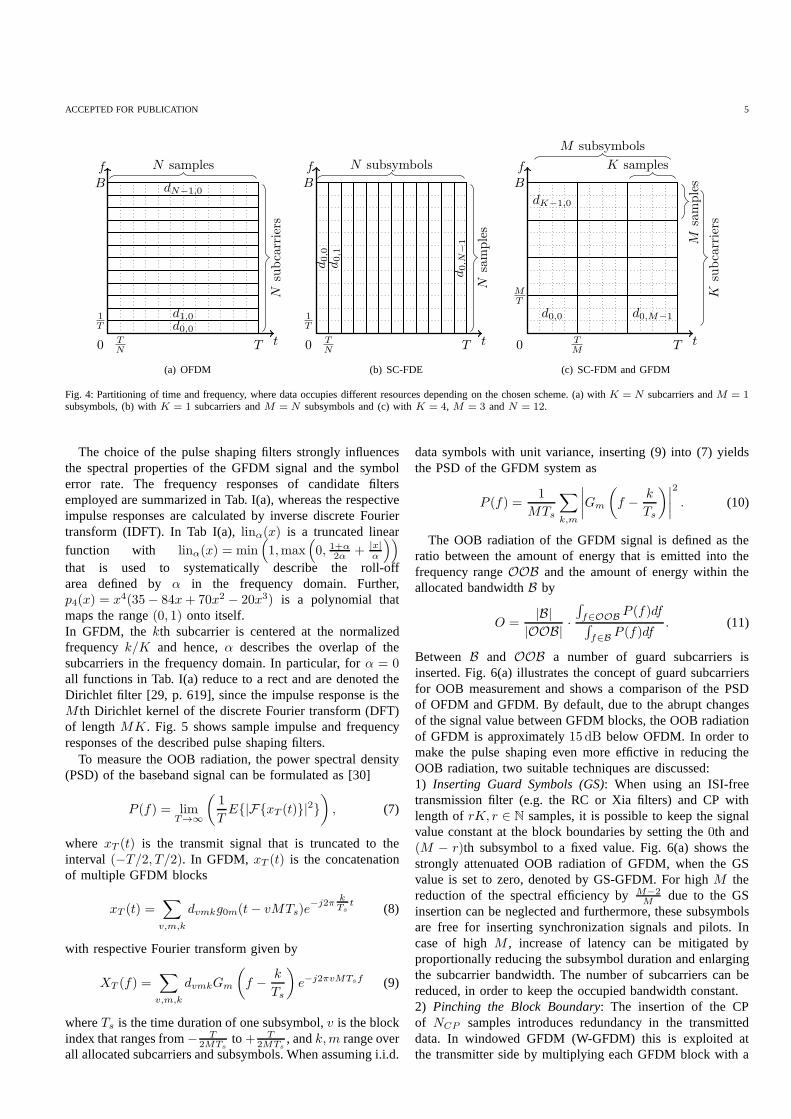
Fig. 4: Partitioning of time and frequency, where data occupies different resources depending on the chosen scheme. (a)with K = N subcarriers andM = 1subsymbols, (b) withK = 1 subcarriers andM = N subsymbols and (c) withK = 4, M = 3 andN = 12.
The choice of the pulse shaping filters strongly influencesthe spectral properties of the GFDM signal and the symbolerror rate. The frequency responses of candidate filtersemployed are summarized in Tab. I(a), whereas the respectiveimpulse responses are calculated by inverse discrete Fouriertransform (IDFT). In Tab I(a),linα(x) is a truncated linear
function with linα(x) = min(
1,max(
0, 1+α2α + |x|
α
))
that is used to systematically describe the roll-offarea defined byα in the frequency domain. Further,p4(x) = x4(35− 84x+ 70x2 − 20x3) is a polynomial thatmaps the range(0, 1) onto itself.In GFDM, the kth subcarrier is centered at the normalizedfrequencyk/K and hence,α describes the overlap of thesubcarriers in the frequency domain. In particular, forα = 0all functions in Tab. I(a) reduce to a rect and are denoted theDirichlet filter [29, p. 619], since the impulse response is theM th Dirichlet kernel of the discrete Fourier transform (DFT)of lengthMK. Fig. 5 shows sample impulse and frequencyresponses of the described pulse shaping filters.
To measure the OOB radiation, the power spectral density(PSD) of the baseband signal can be formulated as [30]
P (f) = limT→∞
(
1
TE{|F{xT (t)}|2}
)
, (7)
where xT (t) is the transmit signal that is truncated to theinterval (−T/2, T/2). In GFDM, xT (t) is the concatenationof multiple GFDM blocks
xT (t) =∑
v,m,k
dvmkg0m(t− vMTs)e−j2π
kTs
t (8)
with respective Fourier transform given by
XT (f) =∑
v,m,k
dvmkGm
(
f − k
Ts
)
e−j2πvMTsf (9)
whereTs is the time duration of one subsymbol,v is the blockindex that ranges from− T
2MTsto+ T
2MTs, andk,m range over
all allocated subcarriers and subsymbols. When assuming i.i.d.
data symbols with unit variance, inserting (9) into (7) yieldsthe PSD of the GFDM system as
P (f) =1
MTs
∑
k,m
∣
∣
∣
∣
Gm
(
f − k
Ts
)∣
∣
∣
∣
2
. (10)
The OOB radiation of the GFDM signal is defined as theratio between the amount of energy that is emitted into thefrequency rangeOOB and the amount of energy within theallocated bandwidthB by
O =|B|
|OOB| ·∫
f∈OOBP (f)df
∫
f∈BP (f)df
. (11)
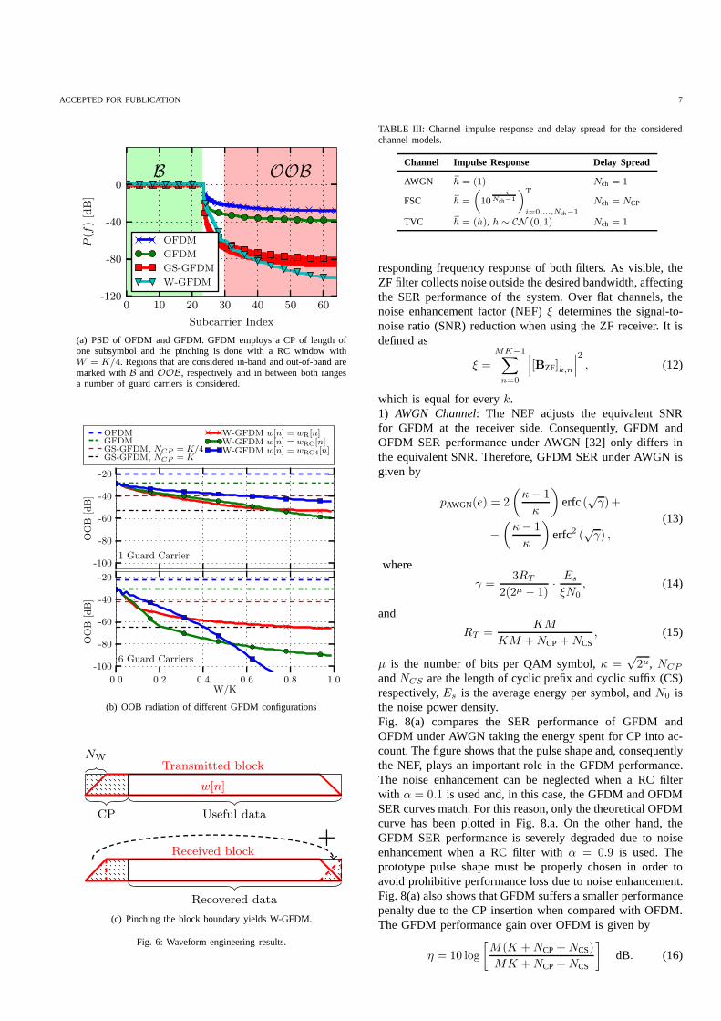
Between B and OOB a number of guard subcarriers isinserted. Fig. 6(a) illustrates the concept of guard subcarriersfor OOB measurement and shows a comparison of the PSDof OFDM and GFDM. By default, due to the abrupt changesof the signal value between GFDM blocks, the OOB radiationof GFDM is approximately15 dB below OFDM. In order tomake the pulse shaping even more effictive in reducing theOOB radiation, two suitable techniques are discussed:1) Inserting Guard Symbols (GS): When using an ISI-freetransmission filter (e.g. the RC or Xia filters) and CP withlength ofrK, r ∈ N samples, it is possible to keep the signalvalue constant at the block boundaries by setting the0th and(M − r)th subsymbol to a fixed value. Fig. 6(a) shows thestrongly attenuated OOB radiation of GFDM, when the GSvalue is set to zero, denoted by GS-GFDM. For highM thereduction of the spectral efficiency byM−2
Mdue to the GS
insertion can be neglected and furthermore, these subsymbolsare free for inserting synchronization signals and pilots.Incase of highM , increase of latency can be mitigated byproportionally reducing the subsymbol duration and enlargingthe subcarrier bandwidth. The number of subcarriers can bereduced, in order to keep the occupied bandwidth constant.2) Pinching the Block Boundary: The insertion of the CPof NCP samples introduces redundancy in the transmitteddata. In windowed GFDM (W-GFDM) this is exploited atthe transmitter side by multiplying each GFDM block with a

6 IEEE TRANSACTIONS ON COMMUNICATIONS
0 2 4 6 8n/K
0.00
0.05
0.10
g[n]
RRC
-0.5 0.5f/M
-0.50.00.51.0
G[f]
0 2 4 6 8n/K
RC
-0.5 0.5f/M
0 2 4 6 8n/K
Xia 1st
-0.5 0.5f/M
0 2 4 6 8n/K
Xia 4th
-0.5 0.5f/M
0 2 4 6 8n/K
Dirichlet
-0.5 0.5f/M
Fig. 5: Impulse and frequency response of employed pulse shaping filters. Roll-off α is set to0.5 except for the Dirichlet filter (α = 0). Solid and dashedlines denote real and imaginary part, respectively.
TABLE I: Pulse shaping filters and window functions.
(a) Investigated pulse shaping filters.
Name Frequency response
RC GRC[f ] =12
[
1− cos(π linα(f
M))]
Root RC GRRC[f ] =√
GRC [f ]
1st Xia [31] GXia[f ] =12
[
1− e−jπ linα(f
M) sign(f)
]
4th Xia [31] GXia4[f ] =12
[
1− e−jπp4(linα(f
M)) sign(f)
]
(b) Window functions for block pinching.
Window Time domain
Rect wRect[n] = 1
Ramp wR[n] = lin NWKM
[
KM+NW2KM
(
2nKM+NCP
− 1)]
RC wRC[n] =12[1− cos(πwR[n])]
4th RC wRC4[n] =12[1− cos(πp4(wR[n]))]
window functionw[n] in the time domain to provide a smoothfade-in and fade-out as illustrated in Fig. 6(c). Differentwindow functions are given in Tab. I(b), whereNW is thenumber of samples that are included in the linear part of therampwR[n]. At the receiver side, the data is recovered fromthe received W-GFDM block by summing the parts of theCP that were modified by the window. As a result, a noiseenhancement of10 log10(1 +
NWKM
)dB occurs because of thesummation of two redundant parts of the signal. This noiseenhancement can be mitigated by using the square root ofthe block window at the transmitter and at the receiver whichresembles the matched filter approach. Calculations of theOOB power have been carried out with the parameters inTab. II, where different CP lengths have been employed. Theresults for one and six guard carriers are shown in Fig. 6(b).Obviously, any of the presented GFDM configurations hasa lower OOB radiation than OFDM. GS-GFDM efficientlyreduces the OOB radiation to 32 dB below OFDM with a CPof K samples. For a CP length ofK/4, GS-GFDM performs20 dB below OFDM. Pinching is most effective in combinationwith a higher number of guard carriers, since the multiplicationwith a block window spreads the spectrum of the GFDMsignal. ThewRC4-window attenuates the OOB radiation withsix guard carriers most, but has the least suppression withone guard carrier due to its wide mainlobe in the frequencydomain. It can attenuate the OOB radiation to below -100 dBas is shown in Fig. 6(b) in the solid blue line. When toleratingsix guard carriers, the pinching technique can supress the OOBradiation below -70 dB with a ramp length of only a quartersubsymbol and an RC window.
IV. SYMBOL ERROR RATE PERFORMANCEANALYSIS
In this section we analyze the performance of the GFDMsystem in terms of SER versusEs/N0 assuming that a ZFreceiver is employed. This type of linear receiver is able toremove self-generated interference at the cost of introducingnoise enhancement, depending on the pulse shape. Differ-ently from previous work, where the bit error rates havebeen analyzed only based on simulations [26], this sectionintroduces analytical expression to evaluate the GFDM SERperformance under AWGN, static frequency-selective channels(FSC) and flat time-variant channels (TVC). Besides the SERperformance analysis, this section provides a trade-off analysisbetween noise enhancement and OOB emissions for differentpulse shapes.
The system parameters used for the simulation are presentedin Tab. II, while Tab. III shows the channel impulse responseused in the SER performance evaluation. Fig. 7(a) shows
TABLE II: Simulation parameters.
Parameter Value
Mapping 16-QAMTransmit Filter RCRoll-off (α) 0.1 or 0.9Number of subcarriers (K) 64Number of subsymbols (M ) 9CP length (NCP) 16 samplesCS length (NCS) 0 samples
the receive filter impulse response for ZF and MF receiversassuming the parameters presented in Tab. II withα = 0.9to highlight the noise enhancement. Fig. 7(b) shows the cor-
ACCEPTED FOR PUBLICATION 7
0 10 20 30 40 50 60
Subcarrier Index
-120
-80
-40
0
P(f
)[dB]
OOBB
OFDM
GFDM
GS-GFDM
W-GFDM
(a) PSD of OFDM and GFDM. GFDM employs a CP of length ofone subsymbol and the pinching is done with a RC window withW = K/4. Regions that are considered in-band and out-of-band aremarked withB andOOB, respectively and in between both rangesa number of guard carriers is considered.
-100
-80
-60
-40
-20
OOB
[dB]
1 Guard Carrier
OFDMGFDMGS-GFDM, NCP = K/4GS-GFDM, NCP = K
W-GFDM w[n] = wR[n]W-GFDM w[n] = wRC[n]W-GFDM w[n] = wRC4[n]
0.0 0.2 0.4 0.6 0.8 1.0W/K
-100
-80
-60
-40
-20
OOB
[dB]
6 Guard Carriers
(b) OOB radiation of different GFDM configurations
CP Useful data
Transmitted block
w[n]
NW
Received block
Recovered data
+
(c) Pinching the block boundary yields W-GFDM.
Fig. 6: Waveform engineering results.
TABLE III: Channel impulse response and delay spread for theconsideredchannel models.
Channel Impulse Response Delay Spread
AWGN ~h = (1) Nch = 1
FSC ~h =
(
10−i
Nch−1
)T
i=0,...,Nch−1
Nch = NCP
TVC ~h = (h), h ∼ CN (0, 1) Nch = 1
responding frequency response of both filters. As visible, theZF filter collects noise outside the desired bandwidth, affectingthe SER performance of the system. Over flat channels, thenoise enhancement factor (NEF)ξ determines the signal-to-noise ratio (SNR) reduction when using the ZF receiver. It isdefined as
ξ =MK−1∑
n=0
∣
∣
∣[BZF]k,n
∣
∣
∣
2
, (12)
which is equal for everyk.1) AWGN Channel: The NEF adjusts the equivalent SNRfor GFDM at the receiver side. Consequently, GFDM andOFDM SER performance under AWGN [32] only differs inthe equivalent SNR. Therefore, GFDM SER under AWGN isgiven by
pAWGN(e) = 2
(
κ− 1
κ
)
erfc(√γ)+
−(
κ− 1
κ
)
erfc2 (√γ) ,
(13)
where
γ =3RT
2(2µ − 1)· Es
ξN0, (14)
and
RT =KM
KM +NCP+NCS, (15)
µ is the number of bits per QAM symbol,κ =√2µ, NCP
andNCS are the length of cyclic prefix and cyclic suffix (CS)respectively,Es is the average energy per symbol, andN0 isthe noise power density.Fig. 8(a) compares the SER performance of GFDM andOFDM under AWGN taking the energy spent for CP into ac-count. The figure shows that the pulse shape and, consequentlythe NEF, plays an important role in the GFDM performance.The noise enhancement can be neglected when a RC filterwith α = 0.1 is used and, in this case, the GFDM and OFDMSER curves match. For this reason, only the theoretical OFDMcurve has been plotted in Fig. 8.a. On the other hand, theGFDM SER performance is severely degraded due to noiseenhancement when a RC filter withα = 0.9 is used. Theprototype pulse shape must be properly chosen in order toavoid prohibitive performance loss due to noise enhancement.Fig. 8(a) also shows that GFDM suffers a smaller performancepenalty due to the CP insertion when compared with OFDM.The GFDM performance gain over OFDM is given by
η = 10 log
[
M(K +NCP+NCS)
MK +NCP+NCS
]
dB. (16)

8 IEEE TRANSACTIONS ON COMMUNICATIONS
0 1 2 3 4 5 6 7 8
−0.1
0
0.1
0.2
Subsymbol index m
g0,0[n]
ZFMF
(a) Impulse response
-6 -4 -2 0 2 4 6−40
−20
0
20
Subcarrier index k
|G0,0[k]|[dB] ZF
MF
(b) Frequency response
Fig. 7: Time and frequency characteristics of the ZF and MF receiving filters.
Hence, a largeM must be chosen if spectrum efficiency isan important requirement in the system design. On the otherhand, it must be noted that latency increases linearly withMin this case. Therefore, when choosing the length of the CP,a trade-off between latency and spectrum efficiency must befound for given applications.2) Frequency-selective channel: A good SER performance overFSCs is an important requirement for multicarrier modulations.Following the block diagram presented in Fig. 1, the signal atthe input of the demapper when the ZF receiver is employedis given by
~̂d = ~d+ ~weq , (17)
where
~weq = BF−1
~W
~H(18)
is the equivalent noise,~W is the noise vector in the frequencydomain, and~H is the vector of the channel frequency response.The variance of the equivalent noise for thelth subcarrier canbe evaluated from (18) and leads to
σ2l =
1
MK
MK−1∑
k=0
∣
∣
∣
∣
GRl,m[−k]
H [k]
∣
∣
∣
∣
2
σ2n = ξlσ
2n = ξl
N0
2, (19)
whereGRl,m[k] is the frequency response of the filter for the
lth subcarrier andmth subsymbol andξl is the correspondingNEF. Notice thatσ2
l is equal for everym. The position of thefilter in the frequency domain changes the NEF because thechannel frequency response is not flat for multipath channels.Hence, the GFDM SER over FSCs is given by
pFSC(e) = 2
(
κ− 1
κK
)K−1∑
l=0
erfc(√γl)+
− 1
K
(
κ− 1
κ
)2 K−1∑
l=0
erfc2 (√γl) ,
(20)
where
γl =3RT
2(2µ − 1)· Es
ξlN0. (21)
GFDM has M times more samples per subcarrier whencompared to OFDM, which provides a higher spectrum reso-lution for equalization, allowing GFDM to better mitigate thefrequency selectivity per subcarrier.Fig. 8(b) compares the performance of GFDM and OFDM
over FSC considering the channel delay profile presented inTab. III with Nch = 16. Again, GFDM uses the CP moreefficiently when compared to OFDM. Notice that the channeldelay profile leads to a coherence bandwidth ofBc ≈ fs/259and the bandwidth of each subcarrier isBsc ≈ fs/64, whichmeans that this channel is frequency-selective per subcarrier.In this scenario, the larger number of samples per subcarriersallows GFDM to present a better performance than OFDM,as shown in Fig. 8(b). In fact, for high SNR, the GFDMperformance when employing an RC filter withα = 0.9 andlarge NEF approaches the OFDM SER.3) Time-variant channel: In a time-variant channel both instan-taneous SNR and instantaneous SER are random variables.Thus, the average symbol error probability over a time-variant channels is an important tool to analyse the systemperformance. Consider that a time-variant channel can bemodelled as a multiplicative channel where the amplitude gainis a Rayleigh random variable with parameterσr and phaseuniformly distributed between−π andπ. It is assumed that thechannel remains static during the transmission of one GFDMsymbol. In this case, the GFDM SER follows the OFDM SERwith the penalty of the noise enhancement when a ZF receiveris employed. Due to the flat property of the channel, the NEFis constant for all subcarriers. Therefore, the SER of GFDMover time-variant channels is given by
pTVC(e) = 2
(
κ− 1
κ
)(
1−√
γr1 + γr
)
+
−(
κ− 1
κ
)2 [
1− 4
π
√
γr1 + γr
atan
(√
1 + γrγr
)]
,
(22)
where
γr =3σ2
rRT
2µ − 1
Es
ξN0. (23)
Fig. 8(c) shows the GFDM and OFDM SER performanceassuming a Rayleigh channel with parameterσ2
r = 12 . Once
again, we can observe that the NEF resulting from the chosenpulse shape is neglectable when compared with OFDM forα = 0.1. GFDM benefits from using only one CP forMsubsymbols, which results in a better power and spectralefficiency.
Closed-form solutions for the SER performance underAWGN of the matched filter receiver are available in [33]. TheMF receiver outperforms the ZF receiver in low SNR regionsdue to the significant influence of the noise enhancement.

ACCEPTED FOR PUBLICATION 9
0 5 10 15 2010−4
10−3
10−2
10−1
100
Es/N0 [dB]
symbolerrorrate
0 5 10 15 20 25
Es/N0 [dB]
Theo. OFDM Theo CP-OFDM Sim. CP-OFDM
Theo. GFDM - RC α = 0.1 Theo. CP-GFDM - RC α = 0.1 Sim. CP-GFDM- RC α = 0.1
Theo. GFDM - RC α = 0.9 Theo. CP-GFDM - RC α = 0.9 Sim. CP-GFDM - RC α = 0.9
0 10 20 30 40
Es/N0 [dB]
(a) AWGN (b) frequency-selective (c) time-variant
Fig. 8: GFDM and OFDM SER performance in different channels.The minimum number of symbol errors for each SNR value is: 500for AWGN andfrequency-selective channels and 20000 for time-variant channel.
-70 -65 -60 -55 -50 -45 -40
OOB [dB]
0
1
2
3
NEF
[dB]
αα
GS-GFDMW-GFDM
RC
RRC
1st order Xia
4th order Xia
Fig. 9: NEF and OOB for various GFDM filters. OOB radiation wasmeasuredwith 6 guard carriers. The W-GFDM system uses a RC window witha ramplength ofK/4. The roll-off α increases in the direction of the arrows from0 to 1 in steps of 0.1.
However, since the MF receiver suffers from self-interference,it cannot reach the performance of the ZF approach at highSNR values. The MMSE receiver balances the noise enhance-ment and self-interference so that it converges to the MFreceiver for low SNR and to the ZF receiver for high SNRregions. However, no closed form solutions for the SER inRayleigh fading channels do exist. Simulated SER curves forthe MMSE receiver are provided in [26]. Fig. 9 shows theOOB radiation and NEF of different filters and different roll-off factors for W-GFDM and GS-GFDM assuming the systemparameters presented in Table II. The choice of the pulseshaping filter significantly influences the NEF and, in case ofGS-GFDM, also the OOB radiation. For W-GFDM the OOBradiation is nearly independent of the employed filter. The NEFincreases with the roll-off factor due to the wider overlappingof the subcarriers. The ZF receiver needs to put more effortinto ICI cancellation which is bought for an increased NEF inthe range from0 dB for the Dirichlet filter up to3.5dB for fullroll-off RRC and 1st order Xia filters. The 4th order Xia filtershows the lowest NEF of1.25 dB with full roll-off. However,
for practical applications, the RC and 4th order Xia filter withlower α in the range of0 ≤ α ≤ 0.2 are preferrable.
V. SPACE-TIME CODED GFDM
Any 5G system shall be able to exploit the benefits of multi-ple transmit and receive antennas. Transmission diversity[24]is a crucial feature for future wireless networks to achievetherequired reliability and robustness under frequency-selectiveand time-variant channels. Due to the orthogonality of thesymbols the Alamouti-STC is easily applied in OFDM [34].For GFDM, the overlapping subsymbols in the time domainimpede the direct application of the Alamouti-STC withinone GFDM block. However, as a major contribution of thissection, we show that the block-structure of GFDM enables theapplication of time-reversal STC, which has been developedfor single carrier systems to achieve diversity under frequency-selective channels [35]. Fig. 10 presents the block diagramsof the STC-GFDM transmitter and receiver.
In this approach, two data vectors~d1 and ~d2 are indepen-dently modulated leading to
~x1 = A~d1 and ~x2 = A~d2. (24)
The modulated signals are delivered to the space-time encoderto produce the signals that will be transmitted by the twoantennas in two successive time frames, which are presentedinTab. IV. A CP is appended to each signal before transmission.
TABLE IV: STC signals.
Antenna 1 Antenna 2
Time frame 1 x11[n] = x1[n] x21[n] = −x∗
2[−n mod N ]Time frame 2 x12[n] = x2[n] x22[n] = x∗
1[−n mod N ]
On the receiver side, the signals at theith receiving antenna

10 IEEE TRANSACTIONS ON COMMUNICATIONS
GFDM
mod.
A
space-time
encoder
CP
CP
~d1, ~d2 ~x1, ~x2
~x11, ~x12
~x21, ~x22
remove
prefix...
...space-time
combiner
GFDM
demod.
B
synch.channel
estimator/
2I
/
2I
~̂d1,
~̂d2
Fig. 10: Transceiver block diagram of the STC-GFDM.
on time frames 1 and 2 are given by
~yi1 = H1i~x11 +H2i~x21 + ~wi1
~yi2 = H1i~x12 +H2i~x22 + ~wi2,(25)
whereHji is the circulant matrix with the impulse responseof the channel between thejth transmitting antenna and theith receiving antenna, and~wi1 and ~wi2 are the noise vectorsreceived byith receiving antenna in the time frames 1 and 2,respectively. It is assumed that the channel coherence timeislarger than two GFDM symbols.The space-time maximum ratio combining is carried out in thefrequency domain to achieve diversity. The combined signalsin the frequency domain are given by
~̂X1 =
∑I
i=1 Ξ∗1i~Yi1 +Ξ2i
~Y ∗i2
∑Ii=1 Ξ
∗1iΞ1i +Ξ∗
2iΞ2i
= ~X1 +
∑I
i=1 Ξ∗1i~Wi1 +Ξ2i
~W ∗i2
∑Ii=1 Ξ
∗1iΞ1i +Ξ∗
2iΞ2i
= ~X1 + ~Weq1
~̂X2 =
∑Ii=1 Ξ
∗1i~Yi2 −Ξ2i
~Y ∗i1
∑I
i=1 Ξ∗1iΞ1i +Ξ∗
2iΞ2i
= ~X2 +
∑Ii=1 Ξ
∗1i~Wi2 −Ξ2i
~W ∗i1
∑I
i=1 Ξ∗1iΞ1i +Ξ∗
2iΞ2i
= ~X2 + ~Weq2
(26)
whereI is the number of receiving antennas,Ξji = FHjiF−1
and ~Yi1 and ~Yi2 are the discrete Fourier transform of~yi1 and~yi2, respectively.The estimated data vectors can be obtained from the combinedsignals presented in (26), therefore
~̂dj = BF−1 ~̂Xj. (27)
Fig. 11 compares the SER performance of classical STC-OFDM [34] with STC-GFDM considering the system param-eters from Tab. II and the frequency selective channel delayprofile from Tab. III, however, each tap of the channel impulseresponse is multiplied by i.i.d. Rayleigh random variableswith parameterσ2
r = 12 . Also, the total transmitting power
is kept constant, which means that each antenna transmitswith half of the available power. Two transmitting antennasand two receiving antennas have been used in this simulation.Fig. 11 shows that STC-GFDM and STC-OFDM achieve thesame diversity gain. In a practical system setup,α shall bechosen small because the NEF can be neglected. Again, STC-GFDM uses the CP more efficiently which leads to a better
0 4 8 12 16 20
10−6
10−4
10−2
100
Es/N0 [dB]
symbol
errorrate
STC-OFDM
STC-GFDM - RC α = 0.1
STC-GFDM - RC α = 0.9
Fig. 11: SER performance of the 2x2 STC-OFDM and STC-GFDM underfrequency-selective and time-variant channel. The minimal number of symbolerrors for each SNR value is 20000.
performance than STC-OFDM when smallα is used. TheNEF becomes significant for high values ofα, resulting ina performance loss. Nevertheless, the diversity gain of2I isachieved by STC-GFDM for both transmit pulses analyzedin this section. As stated in Sec. IV, GFDM has a higherspectrum resolution per subcarrier, which allows for a betterfrequency domain equalization. The benefit of a more preciseequalization can be also observed in Fig. 11, where theslopes of the STC-GFDM curves are steeper than for STC-OFDM. Hence, even STC-GFDM employing RC withα = 0.9performs better than STC-OFDM for high SNR (Es/N0 > 18dB).
VI. B LOCK BASED SYNCHRONIZATION
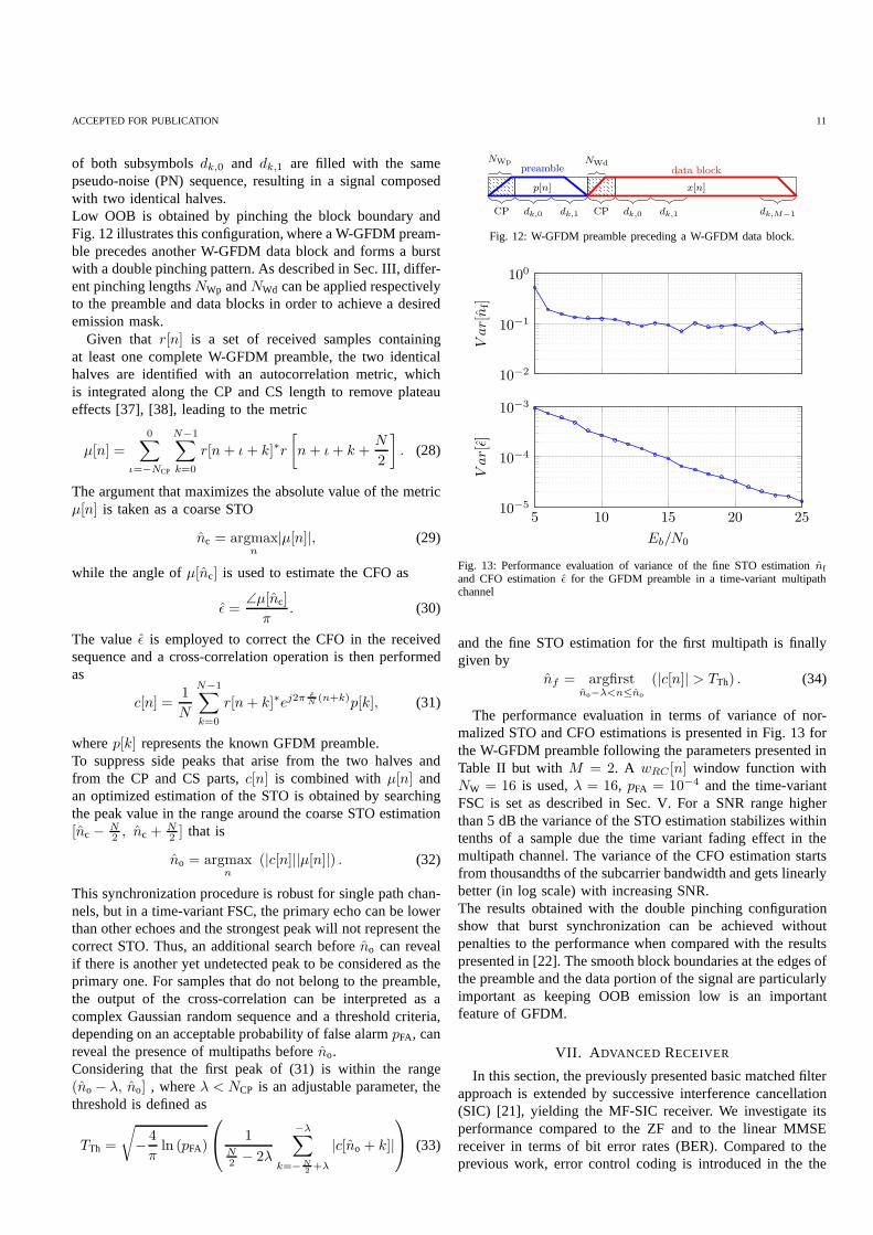
Synchronization is a key element in the performance ofthe signal processing carried out on receivers and can beachieved in GFDM on a block basis. The block structure withits CP allows adaptation of fundamental OFDM solutions toestimate symbol time offset (STO) and carrier frequency offset(CFO) [36], [37], but low OOB is a factor to be specificallyconsidered in GFDM.The algorithm proposed in [22] will be evaluated in this sectionto achieve one-shot synchronization using a straightforwardproposal of a separated W-GFDM preamble, which is definedwith M = 2 and the transmitted data in thekth subcarriers
ACCEPTED FOR PUBLICATION 11
of both subsymbolsdk,0 and dk,1 are filled with the samepseudo-noise (PN) sequence, resulting in a signal composedwith two identical halves.Low OOB is obtained by pinching the block boundary andFig. 12 illustrates this configuration, where a W-GFDM pream-ble precedes another W-GFDM data block and forms a burstwith a double pinching pattern. As described in Sec. III, differ-ent pinching lengthsNWp andNWd can be applied respectivelyto the preamble and data blocks in order to achieve a desiredemission mask.
Given that r[n] is a set of received samples containingat least one complete W-GFDM preamble, the two identicalhalves are identified with an autocorrelation metric, whichis integrated along the CP and CS length to remove plateaueffects [37], [38], leading to the metric
µ[n] =
0∑
ι=−NCP
N−1∑
k=0
r[n+ ι+ k]∗r
[
n+ ι+ k +N
2
]
. (28)
The argument that maximizes the absolute value of the metricµ[n] is taken as a coarse STO
n̂c = argmaxn
|µ[n]|, (29)
while the angle ofµ[n̂c] is used to estimate the CFO as
ǫ̂ =∠µ[n̂c]
π. (30)
The valueǫ̂ is employed to correct the CFO in the receivedsequence and a cross-correlation operation is then performedas
c[n] =1
N
N−1∑
k=0
r[n+ k]∗ej2πǫ̂N
(n+k)p[k], (31)
wherep[k] represents the known GFDM preamble.To suppress side peaks that arise from the two halves andfrom the CP and CS parts,c[n] is combined withµ[n] andan optimized estimation of the STO is obtained by searchingthe peak value in the range around the coarse STO estimation[n̂c − N
2 , n̂c +N2 ] that is
n̂o = argmaxn
(|c[n]||µ[n]|) . (32)
This synchronization procedure is robust for single path chan-nels, but in a time-variant FSC, the primary echo can be lowerthan other echoes and the strongest peak will not represent thecorrect STO. Thus, an additional search beforen̂o can revealif there is another yet undetected peak to be considered as theprimary one. For samples that do not belong to the preamble,the output of the cross-correlation can be interpreted as acomplex Gaussian random sequence and a threshold criteria,depending on an acceptable probability of false alarmpFA, canreveal the presence of multipaths beforen̂o.Considering that the first peak of (31) is within the range(n̂o − λ, n̂o] , whereλ < NCP is an adjustable parameter, thethreshold is defined as
TTh =
√
− 4
πln (pFA)
1N2 − 2λ
−λ∑
k=−N2+λ
|c[n̂o + k]|
(33)
CP dk,0 dk,1
preamble
p[n]
NWp
CP dk,0 dk,1 dk,M−1
data block
x[n]
NWd
Fig. 12: W-GFDM preamble preceding a W-GFDM data block.
10−2
10−1
100
Var[n̂f]
5 10 15 20 2510−5
10−4
10−3
Eb/N0
Var[ǫ̂]
Fig. 13: Performance evaluation of variance of the fine STO estimation n̂fand CFO estimation̂ǫ for the GFDM preamble in a time-variant multipathchannel
and the fine STO estimation for the first multipath is finallygiven by
n̂f = argfirstn̂o−λ<n≤n̂o
(|c[n]| > TTh) . (34)
The performance evaluation in terms of variance of nor-malized STO and CFO estimations is presented in Fig. 13 forthe W-GFDM preamble following the parameters presented inTable II but withM = 2. A wRC [n] window function withNW = 16 is used,λ = 16, pFA = 10−4 and the time-variantFSC is set as described in Sec. V. For a SNR range higherthan 5 dB the variance of the STO estimation stabilizes withintenths of a sample due the time variant fading effect in themultipath channel. The variance of the CFO estimation startsfrom thousandths of the subcarrier bandwidth and gets linearlybetter (in log scale) with increasing SNR.The results obtained with the double pinching configurationshow that burst synchronization can be achieved withoutpenalties to the performance when compared with the resultspresented in [22]. The smooth block boundaries at the edges ofthe preamble and the data portion of the signal are particularlyimportant as keeping OOB emission low is an importantfeature of GFDM.
VII. A DVANCED RECEIVER
In this section, the previously presented basic matched filterapproach is extended by successive interference cancellation(SIC) [21], yielding the MF-SIC receiver. We investigate itsperformance compared to the ZF and to the linear MMSEreceiver in terms of bit error rates (BER). Compared to theprevious work, error control coding is introduced in the the

12 IEEE TRANSACTIONS ON COMMUNICATIONS
GFDM demodulator
ZF/MMSE
softdemapper
iterativedecoder
~z~̂d
~̂bc
~̂b
(a) ZF and MMSE receiver configuration
GFDM demodulator
+ MFsoft
demapperiterative
decoder
SIC
~z ~z(ℓ) ~̂
d(ℓ) ~̂
bc~̂b
~u(ℓ)
(b) MF-SIC receiver configuration
Fig. 14: The considered receiver configurations.
setup. The results show that although ZF can severely enhancethe noise in the system, it can be a reasonable alternative totheiterative approach in some cases, mainly when small values ofα andM are employed.
A non-orthogonal waveform like GFDM inherently in-troduces correlation across all subcarriers and subsymbolswithin a block, which can result in unwanted self-interferenceamong the elements of~̂d, when the MF receiver is employed.Supposedℓ is the iteration index, the algorithm starts by
first detecting all data symbols~̂d(ℓ), ℓ = 0 based on thereceived signal~z. In the first iterationℓ = 1, the detected
data symbols~̂d(0) are then fed back to calculate a cancellation
signal~u(ℓ)k,m = A
~̂d(ℓ−1) − ~gk,md̂k,m for each pair of(k,m),
which is based on all but the(k,m)th element of ~̂d(ℓ−1).The received and equalized signal~z is partially cleaned ofinterference, producing~z(ℓ)k,m = ~z+ ~u
(ℓ)k,m. Lastly, the(k,m)th
data symbol is detected again to obtaind̂(ℓ)k,m. Theℓth iteration
is complete once all pairs of(k,m) are run through. The totalnumber of SIC iterations shall be denoted byJSIC.This method has been shown to be effective, even for highorder of QAM mapping [39]. However, for largeK andMthis can significantly increase the computational complexityof the receiver. In this case, using a Nyquist filter allows toelimininate self-intersymbol-interference and thus requires toiterate only through the subcarriers in the system. Anotheroption is to define a threshold for〈~gk′,m′ , ~gk,m〉 with k 6= k′
andm 6= m′, below whichdk′,m′ is considered not to haveinfluence ond̂k,m.Additionally, an interesting question is, to what degreecan coding help to overcome the impairments of the non-orthogonal waveform. To investigate this, encoder and decoderare introduced in the transmission chain. The parallel concate-nated convolutional code (PC-CC) from [40] with code rateR = 1/3 is considered for this section. On the receiver side,a turbo decoder [41] withJTD iterations is employed.
In the following, the two configurations depicted in Fig. 14shall be considered. In the first setup, a linear receiver, i.e. ZFor linear MMSE, is utilized in combination with the turbo
decoder. The second setup employs MF with several SICiterations prior to decoding. As a reference, an orthogonalSC-FDM transmission is used. The performance is comparedin terms of bit error rates in AWGN, frequency-selective andtime-variant channels from Tab. III and the configuration ofthe GFDM system is based on Tab. II.The main objective here is to evaluate the penalty of usinga non-orthogonal waveform. Generally, when the transmitfilter exhibits little self-interference (α = 0.1), for either ofMF and ZF, the PC-CC alone is able to close the gap tothe orthogonal system. In a situation where the interferencebecomes severe (α = 0.9), MF and ZF can strongly deviatefrom the performance of the orthogonal system. Looking atthe AWGN case, noise enhancement appears to have a moresevere impact than the self-interference as MF outperformsZF.However, with increasingEb/N0 in the frequency selectivechannel, the MF can only outperform the ZF, when combinedwith SIC. This behaviour is similar in the time-variant channel,however here a pronounced waterfall region is absent. In thecase of strong self-interference, the performance of the MMSEreceiver is comparable to MF-SIC for the time-variant channel,while MF-SIC outperforms it by0.5dB for high SNR inAWGN conditions and by an even smaller fraction of thatin the frequency-selective channel.Overall, it can be concluded that when operating with littleself-interference, ZF should be favored as ZF and MF-SICshow nearly identical performance, but ZF does not entailthe complexity overhead of the SIC iterations. When self-interference is severe, MF-SIC outperforms at the cost ofmore computational effort. The MMSE achieves similar per-formance as the ZF receiver, when looking at the frequency-selective or the time-variant channel.
VIII. A PPLICATION REQUIREMENTS
New scenarios are being foreseen for 5G networks withrequirements that cannot be addressed only with throughputincrement. In this section, we present a short description ofthe most prominent application scenarios and propose setsof GFDM parameters to address the specific requirements.In particular, adequate values ofK and M based on therestrictions from the wireless channel characteristics and onthe requirements of the application scenarios are established.Table V presents the typical channel parameters and a sug-gested GFDM configuration for each scenario. The applicationscenarios considered in this section are:1) Bitpipe communication: Currently broadcasting services areexperiencing a media shift, where television and radio contentare being broadcasted through the Internet. People demandtheir favorite shows anywhere, and smartphones and tabletsarecommonly used to access the content. With screen resolutionon mobile devices beyond high definition, videos and 3D con-tents will require several tens of Mbps to achieve a good Qual-ity of Experience (QoE). Therefore, next generation networksmust rely on advanced digital communication techniques, suchas MIMO [23] for diversity and multiplexing, highly efficientchannel coding, small cell coverage with inter-cell interferencemanagement and efficient dynamic spectrum allocation. For

ACCEPTED FOR PUBLICATION 13
0 2 4 610−4
10−3
10−2
10−1
100
Eb/N0 [dB]
biterrorprobability
11 13 15 17
Eb/N0 [dB]
MF-SIC α = 0.1 MF-SIC α = 0.9, ℓ = 0 MF-SIC α = 0.9, ℓ = 1ZF α = 0.1 ZF α = 0.9 MMSE α = 0.9SC-FDM
0 10 20 30
Eb/N0 [dB]
(a) AWGN (b) frequency-selective (c) time-variant
Fig. 15: BER simulation results for a coded system withJTD = 10 andJSIC = 1.
waveform engineering, low out-of-band emission is a crucialrequirement to allow fragmented and opportunistic spectrumallocation with cognitive radios (CR) [42]. Orthogonal Fre-quency Division Multiplexing (OFDM) [6] with−35dBcOOB emissions will hardly be able to attend the emission maskwithout additional filtering, which renders the deploymentofOFDM questionable in the next generation standards.As presented in Section IV, GFDM can achieve OOB emissionseveral dBs below OFDM and, therefore, is more suitableto explore vacant and fragmented spectrum. Besides the lowOOB emission, GFDM configuration with largeM can reducethe impact of the CP length in the overall throughput andcan significantly increase the spectrum efficiency. GFDMcombined with Coordinated Multipoint transmission [43] canincrease the spectrum re-use in small cell networks withoutincreasing the interference between cells.
2) Machine Type Communication (MTC): Machines, devicesand even objects are becoming intelligent and equippedwith sensors, which increasingly allow them to operate au-tonomously and to communicate without human interaction.While today’s MTC is mainly based on short-range wirelesstechnologies, such as Bluetooth and Zigbee, it is expectedthat cellular systems providing wide area coverage will gain asignificant market share. There are two major markets foreseenfor MTC. The first considers machines as complete systemswith only an interface that allows for controlling it overthe Internet. The other considers machines as sensors andactuators where all the control system is to be moved toa cloud infrastructure. Although the first approach can beimplemented shortly, the second one is regarded as the mostinteresting because the connected sensors will provide accurateinformation for Big Data processing [44], allowing for dataanalytics to uncover patterns and correlations, and offer newor better services. Consider a scenario, where smart devices ina given environment communicate among each other or witha central station without human intervention. These devices
CP data data data data data data data CS
CP data CP data CP data CP data CP data CP data CP data
GFDM
OFDM
Fig. 16: GFDM and OFDM frame comparison for the MTC scenario.
are typically powered by batteries and their lifetime mustbe extended. MTC devices connecting to cellular networkscannot pass through all the synchronization steps, becausethis process would consume a large amount of energy. Hence,MTC devices must be able to achieve reliable communicationwith a loose synchronization or even operate asynchronously.A large CP and CS can be used to allow for loose time domainsynchronization in a random access channel [15], but thisapproach cannot be efficiently used with OFDM as it requiresone CP and CS per symbol. GFDM applies one CP and one CSin a block with several subsymbols. Therefore, a LTE resourceblock can be organized as a GFDM block with CP andCS large enough to accommodate timing misalignment (seeFigure 16). It is worth noting that GFDM is able to increasethe size of the CP and introduce a CS without consumingfurther resources when compared with the LTE approach.3) Tactile Internet: This new application scenario is firstenvisioned in [4], where the 5G network is used for real-time control applications with at most1ms round-trip latencyrequirements. The low latency requirement is determined bythe typical interaction latency for tactile steering and controlof real and virtual objects. In fact, most of today’s mobiledevices use a touch screen as input interface and future deviceswill integrate various interfaces for haptic, visual and auditoryinput and feedback. These new interface devices are alsogoing to be used to interact with the online environment forvirtual and augmented reality, health monitoring, smart housecontrolling, gaming and many different applications. If too

14 IEEE TRANSACTIONS ON COMMUNICATIONS
TABLE V: Channel and system parameters for the identified application scenarios.
Parameters Bitpipe Tactile Internet MTC WRAN
Cell size [km] 4 1 4 100Delay Spread [µs] 5 1 5 50Bc [kHz] 40 200 40 4Doppler shift [Hz] 100 10 100 10Tc [ms] 5 50 5 50SubcarriersK 20,1,2,...,8 64 or 128 1 20,1,...,4
SubsymbolsM 1023 ... 5 5 7 1023 ... 127Receiver type MF-SIC ZF ZF MF-SICTCP [µ] 7 2 7 80Symbol duration [µs] ≤ 5000 ≈ 5 ≈ 500 ≤ 50000Modulation order 2, 4, 6 or 8 2 or 4 2 2, 4, 6 or 8Bw [MHz] 20 100 (Fragmented) 1 5, 10 or 20
large, the round-trip delays between the command insertion,the action in the online environment and the feedback canresult in a poor QoE or even cybersickness. Since the overallround-trip system delay cannot be larger than1ms, the timebudget for the physical layer will be of no more than hundredsof µs. The current frame structure of Long Term Evolution(LTE), based on70µs OFDM symbols, has a latency that isat least one order of magnitude above the target for the TactileInternet. GFDM can address this application by having a smallMK product. This approach will lead to larger bandwidth persubcarrier, which means that each one might suffer from chan-nel frequency-selectiveness. Nevertheless, because GFDMhasM samples per subcarrier, FDE can be applied in this case.
4) WRAN: Despite the fact that reasonable Internet accessis available in cities, sparsely populated areas suffer fromlow data rate and unreliable solutions. Wired technologieshave limited coverage and require large investments. Today’swireless networks have relatively small cell size and oper-ate in licensed frequencies, which makes them economicalunfeasible in low populated areas. CR technology addressesthis problem by dynamically and opportunistically accessingvacant UHF TV bands. When using OFDM as the air interface,it is a challenge to attend the emission mask imposed byspectrum regulation. Besides this, large cell coverage leadsto high delay spread and the conventional OFDM with a CPfor every symbol will result in a low spectral efficiency. Thenext generation network shall address large coverage areasusing dynamic channel allocation based on CR with low OOBemissions and efficiently deal with the multipath effects byreducing the impact of the CP in the overall data rate.Although a long CP is requested to avoid ISI, in this scenariothe user terminals are typically static and Doppler effect playsa small role. Slow time-variant channels allow for GFDMblocks with largeM , whereas the increased latency is notcritical to the WRAN application scenarios and CP and CScan be efficiently used to avoid ISI and time misalignment.In general, the channel characteristics, such as coherencetime(Tc) and coherence bandwidth (Bc), impose a restriction tothe number of subsymbols and subcarriers. The coherencetime defines an upper boundary forMK, while the coherencebandwidth defines a lower bound according to
Rs
Bc
(1 + α) < MK < TcRs, (35)
whereRs is the overall symbol rate.In summary, flexibility will be one key aspect for future
cellular systems in order to address the wide range of foreseenapplication scenarios. GFDM in particular can address therequirements of these application scenarios where the con-figuration of the number of subcarriers and subsymbols is animportant feature.
IX. PROTOTYPE IMPLEMENTATION
The GFDM scheme has been implemented as proof-of-concept on a FPGA based platform. The theoretical foun-dations for the transceiver algorithms are provided in [39]and [45]. Both, the transmitter and the receiver implementationexploit the fact that the corresponding filters are limited to Lsubcarriers in the frequency domain and this section exploresa way of realizing valuesL > 2 on the receiver side. In orderto utilize the parallel processing capabilities of the FPGAin apipelining structure, the transmit and receiver filter frequencyresponses are split intoL groups ofM samples according to
F [k] = DFTLM
{
(−1)ng[
KLn]}
Fl[j] = F [lM + j],(36)
where k = 0, . . . , LM − 1, j = 0, . . . ,M − 1, g[n] isthe impulse response of the prototype transmit or receivefilter, the factorK
Lcorresponds to a decimation in time, and
(−1)n causes a FFT shift in the frequency domain. At thetransmitter the standard RC and Xia filters limited toL = 2are implemented. The frequency response of the receiverfilter depends on the receiver type. For a smallα it can bereasonably limited toL = 2 andL = 16 for the MF and ZFreceiver, respectively (cf. Fig. 7). The main contributionof thissection is to present a receiver structure that is not limited toa specific receiver type but works with any given filter.
The transmitter pipeline structure is shown in Fig. 17(a). Ineach pipeline iteration,M samples of data in the frequencydomain are sent through a filter delay chain. Finally, the timedomain signal is acquired by IDFT of the frequency samples.Circularity in the frequency domain is achieved by initializingthe delay block with the data of the last subcarrier.Fig. 17(b) illustrates the corresponding receiver structure. Dueto a higher bandwidth of the receiver filter, more delays andfilter blocks are required. However, these will work in parallelon the FPGA which does not increase the overall delay, but the

ACCEPTED FOR PUBLICATION 15
GFDM modulator
~dk FFTM/M
D
F0
F1
+
Store
and
move
IFFTKM ~x/KM
(a) Transmitter
GFDM demodulator
~z FFTKM/KM
Read
and
move
FL−1 +
DL−2
FL−2 +
Dl
Fl +
D0
F0
IFFTM~̂dk
/M
(b) Receiver
Fig. 17: Implementation structure of GFDM transmitter and receiver. Drepresents a delay ofM samples.
occupied area in the chipset. The received time domain signalis first transformed to the frequency domain and then sentthrough the filter delay chain. The required decimation in timeby a factorL is achieved by the summation of theL separatelyfiltered groups before taking the IFFT of the data. Circularityfor every subcarrier is achieved by initializing the delayblocks according toDl[j] = X [j + (K − L+ 1 + l)M ]. Atthe output of the receiver, the subcarriers are delivered with adelay ofL/2− 1 due to the filter bandwidth.
To verify the practical feasibility of the low-complexityGFDM transceiver structure, a software defined radio platformwas designated for its implementation. The demonstrator con-sists of a National Instruments PXI [46] PC-based platformincluding an Intel i7 general purpose processor (GPP) forcontrolling the application and performing basic basebandprocessing and a FlexRIO 7965 FPGA module for high-throughput baseband processing. NI FlexRIO provides user-programmable FPGA modules coupled to interchangeable I/Oadapter modules, such as the NI-5791 RF transceiver module.The latter has a continuous frequency coverage from200MHzto 4.4GHz, 100MHz of instantaneous bandwidth on bothtransmitter and receiver, and performs signal up- and down-conversion to and from radio frequencies. The hardware andsoftware components of this platform are integrated with theLabVIEW graphical programming language.The GFDM transceiver was fully implemented on the FPGAof the platform, realizing the pipeline structure as describedin this section. The parameter configuration in Tab. VI isflexible, which allows to cover a variety of different GFDMapplications.
The GFDM implementation makes use of the Xilinx FFTIP core [47]. This IP core supports a pipelined streamingarchitecture for continuous data processing and a run-timeconfigurable transform point size that can be a positive integerpower of two. Compiling the GFDM transmitter for a Xilinx
TABLE VI: Implementation parameters.
Parameter Value
Number of subcarriers (K) 23,4,...,12
Number of subsymbols (M ) 23,4,...,7
Block length (N = KM ) 26 ≤ N ≤ 215
Modulation scheme QPSK, 16QAM, 64QAMFilter configurableUsed subcarrier mapping configurableBandwidth 10... 30MHzCP length 0 . . . 3K samples
TABLE VII: Compilation results.
Resources Value
Total Slices 73,3% (10783 out of 14720)Slice Registers 44,3% (26104 out of 58880)Slice LUT 48,6% (28642 out of 58880)DSP48s 19,7% (126 out of 640)Block RAMs 80,3% (196 out of 244)
Virtex-5 SX95T FPGA platform uses around 75% of the chipresources. Detailed results of the compilation are presented inthe Tab. VII. The digital baseband processing uses a parallelstructure with different timed loops and a first-in-first-out(FIFO) memory approach to exchange data among processingblocks. Notice that the design also includes advanced debug-ging features that allow collection of internal data and thecontrol of system parameters through an external graphicaluser interface (GUI) developed with LabVIEW. The bottleneckin the system is the loop that feeds the DAC. With typicalbandwidths being in the range between20MHz and50MHz,the current design is capable to generate GFDM blocks of upto 32768 samples length continuously.
The complete base implementation verifies that GFDM canbe implemented with reasonable complexity using today’stechnology. The prototype is the core of our 5G wirelesstestbed for experimental research and will be extended by moreadvanced algorithms and additional PHY layer features, suchas framing, channel coding, and data interfaces in the future.
X. CONCLUSIONS
A novel modulation proposal for a 5G physical layer needsto address the specific requirements described in this paper.The first key property of a future waveform is flexibility, sothat different applications can be addressed by a single solutionwith different parameter settings instead of multiple solutions.This flexibility includes the partitioning of time and frequencyresources, as well as means for spectrum engineering. Thelatter property is especially useful to control the impact ofinterference among multiple users and between systems inadjacent frequency bands. It is also important to guaranteeaharmonious coexistence with other technologies, as we experi-ence today with 4G networks operating in the so called DigitalDividend. Typically, filtering needs to be introduced on thetransmitter or receiver side to achieve coexistence. But doingso, chances are that orthogonality will be forfeit. Nevertheless,the proposed scheme should still be capable of MIMO, andsynchronization and channel estimation should preferablybeeasy to implement. Also error rate performance should not
16 IEEE TRANSACTIONS ON COMMUNICATIONS
be neglected, once the focus is shifted towards robustnessfor certain applications. In this respect, the proposed schemeneeds to be as good as state-of-the art orthogonal waveforms,if not outperform them. Lastly, a laboratory proof-of-conceptis desirable, in order to validate the feasibility of the proposal.In this work, we have presented GFDM as a candidate wave-form modulation scheme for the air interface of future 5Gnetworks. We have shown how the requirements imposed bythe different envisioned application scenarios can be addressedwith a flexible block structure and subcarrier filtering and havepresented suitable parameter configurations for these scenar-ios. We have introduced two techniques, which in addition tothe subcarrier filter address the requirement of low out-of-bandradiation and presented a preamble based synchronizationscheme that preserves these low spectral emission. We haveanalyzed the error rate performance of GFDM analytically andnumerically for various channel conditions and with iterativereceivers, yielding several GFDM configurations that haveno penalties compared to OFDM and SC-FDE. We haveaddressed MIMO-GFDM as a mean to obtain diversity in thesystem and lastly presented a proof-of-concept implementa-tion.Certainly, many more issues still need to be resolved. Never-theless, this paper has shown that GFDM is a novel modulationtechnology with the potential to fulfill the requirements ofthenext generation of mobile wireless systems.
REFERENCES
[1] G. Fettweis and S. Alamouti, “5G: Personal Mobile Internet Beyond
What Cellular Did to Telephony,”IEEE Communications Magazine,
vol. 52, no. 2, pp. 140–145, Feb. 2014.
[2] G. Wunder, P. Jung, M. Kasparick, T. Wild, F. Schaich, Y. Chen,
S. Brink, I. Gaspar, N. Michailow, A. Festag, L. Mendes, N. Cassiau,
D. Ktenas, M. Dryjanski, S. Pietrzyk, B. Eged, P. Vago, and F.Wied-
mann, “5GNOW: Non-Orthogonal, Asynchronous Waveforms forFuture
Mobile Applications,” IEEE Communications Magazine, vol. 52, no. 2,
pp. 97–105, Feb. 2014.
[3] Y. Ding, Y. Jin, L. Ren, and K. Hao, “An Intelligent Self-Organization
Scheme for the Internet of Things,”IEEE Computational Intelligence
Magazine, vol. 8, no. 3, pp. 41–53, Aug. 2013.
[4] G. P. Fettweis, “The Tactile Internet: Applications andChallenges,”
IEEE Vehicular Technology Magazine, vol. 9, no. 1, pp. 64–70, Mar.
2014.
[5] N. Tadayon and S. Aissa, “Modeling and Analysis of Cognitive Radio
Based IEEE 802.22 Wireless Regional Area Networks,”IEEE Transac-
tions on Wireless Communications, vol. 12, no. 9, pp. 4363–4375, Sep.
2013.
[6] J. Bingham, “Multicarrier Modulation for Data Transmission: An Idea
Whose Time Has Come,”IEEE Communications Magazine, vol. 28,
no. 5, pp. 5–14, May 1990.
[7] M. Mirahmadi, A. Al-Dweik, and A. Shami, “BER Reduction of OFDM
Based Broadband Communication Systems over Multipath Channels
with Impulsive Noise,”IEEE Transactions on Communications, vol. 61,
no. 11, pp. 4602–4615, Nov. 2013.
[8] S. Fechtel and A. Blaickner, “Efficient FFT and EqualizerImplementa-
tion for OFDM Receivers,”IEEE Transactions on Consumer Electronics,
vol. 45, no. 4, pp. 1104–1107, Nov. 1999.
[9] J. Kim, J. Lee, J. Kim, and J. Yun, “M2M Service Platforms:Survey,
Issues, and Enabling Technologies,”IEEE Communications Surveys &
Tutorials, vol. 16, no. 1, pp. 61–76, 2014.
[10] M. Nekovee, “Quantifying Performance Requirements ofVehicle-to-
Vehicle Communication Protocols for Rear-End Collision Avoidance,” in
Proc. IEEE 69th Vehicular Technology Conference, vol. 1. Barcelona,
Spain: IEEE, Apr. 2009, pp. 1–5.
[11] H. Kim, J. Kim, S. Yang, M. Hong, and Y. Shin, “An Effective MIMO-
OFDM System for IEEE 802.22 WRAN Channels,”IEEE Transactions
on Circuits and Systems II: Express Briefs, vol. 55, no. 8, pp. 821–825,
Aug. 2008.
[12] J. Van De Beek and F. Berggren, “Out-of-Band Power Suppression in
OFDM,” IEEE Communications Letters, vol. 12, no. 9, pp. 609–611,
Sep. 2008.
[13] E. Hossain,Dynamic Spectrum Access and Management in Cognitive
Radio Networks. Cambridge University Press, 2009.
[14] B. Farhang-Boroujeny, “OFDM Versus Filter Bank Multicarrier,” Signal
Processing Magazine, IEEE, vol. 28, no. 3, pp. 92–112, May 2011.
[15] V. Vakilian, T. Wild, F. Schaich, S. ten Brink, and J.-F.Frigon,
“Universal-Filtered Multi-Carrier Technique for Wireless Systems Be-
yond LTE,” in 9th International Workshop on Broadband Wireless
Access (BWA’13) co-located with IEEE Globecom’13, Atlanta, GA,
USA, Dec. 2013.
[16] R. Ayadi, M. Siala, and I. Kammoun, “Transmit/Receive Pulse-Shaping
Design in BFDM Systems over Time-Frequency Dispersive AWGN
Channel,” in Proceedings IEEE International Conference on Signal
Processing and Communications (ICSPC’07), Dubai, UAE, Nov. 2007,
pp. 772–775.
[17] H. G. Feichtinger and T. Strohmer, Eds.,Advances in Gabor Analysis,
ser. Applied and Numerical Harmonic Analysis. Boston: Birkhauser,
2003.
[18] C. Lélé, P. Siohan, and R. Legouable, “The Alamouti Scheme with
CDMA-OFDM/OQAM,” EURASIP Journal on Advances in Signal
Processing, vol. 2010, pp. 1–14, 2010.
[19] G. Fettweis, M. Krondorf, and S. Bittner, “GFDM – Generalized
Frequency Division Multiplexing,” inProceedings 69th IEEE Vehicular
Technology Conference (VTC Spring’09), Barcelona, Spain, Apr. 2009.
[20] D. Falconer, S. Ariyavisitakul, A. Benyamin-Seeyar, and B. Eidson,
“Frequency Domain Equalization for Single-Carrier Broadband Wireless
Systems,”Communications Magazine, IEEE, vol. 40, no. 4, pp. 58–66,
2002.
[21] R. Datta, N. Michailow, M. Lentmaier, and G. Fettweis, “GFDM
Interference Cancellation for Flexible Cognitive Radio PHY Design,” in
Proceedings 76th IEEE Vehicular Technology Conference (VTC Fall’12),
Québec City, Canada, Sep. 2012, pp. 1–5.
[22] A. Awoseyila, C. Kasparis, and B. G. Evans, “Improved Preamble-Aided
Timing Estimation for OFDM Systems,”IEEE Communications Letters,
vol. 12, no. 11, pp. 825–827, Nov. 2008.
[23] E. Biglieri, MIMO Wireless Communications. Cambridge: Cambridge
University Press, 2010.
[24] S. Alamouti, “A Simple Transmit Diversity Technique for Wireless
Communications,”IEEE Journal on Selected Areas in Communications,
vol. 16, no. 8, pp. 1451–1458, Oct. 1998.
[25] I. Bravo, M. Mazo, J. Lazaro, P. Jimenez, A. Gardel, and M. Marron,
“Novel HW Architecture Based on FPGAs Oriented to Solve the
Eigen Problem,”Very Large Scale Integration (VLSI) Systems, IEEE
Transactions on, vol. 16, no. 12, pp. 1722–1725, Dec 2008.

ACCEPTED FOR PUBLICATION 17
[26] N. Michailow, S. Krone, M. Lentmaier, and G. Fettweis, “Bit Error
Rate Performance of Generalized Frequency Division Multiplexing,” in
Proceedings 76th IEEE Vehicular Technology Conference (VTC Fall’12),
Québec City, Canada, Sep. 2012, pp. 1–5.
[27] S. M. Kay, “Fundamentals of statistical signal processing: detection
theory,” 1998.
[28] N. Michailow and G. Fettweis, “Low Peak-to-Average Power Ratio for
Next Generation Cellular Systems with Generalized Frequency Division
Multiplexing,” in Proceedings International Symposium on Intelligent
Signal Processing and Communications Systems (ISPACS’13), Naha,
Okinawa, Japan, Nov. 2013, pp. 651–655.
[29] B. S. Thomson, J. B. Bruckner, and A. M. Bruckner,Real Analysis.
ClassicalRealAnalysis. com, 2008.
[30] T. van Waterschoot, V. Le Nir, J. Duplicy, and M. Moonen,“Analytical
Expressions for the Power Spectral Density of CP-OFDM and ZP-
OFDM Signals,” Signal Processing Letters, IEEE, vol. 17, no. 4, pp.
371–374, Apr. 2010.
[31] X. Xia, “A Family of Pulse-Shaping Filters with ISI-Free Matched and
Unmatched Filter Properties,”IEEE Transactions on Communications,
vol. 45, no. 10, pp. 1157–1158, 1997.
[32] B. Sklar, Digital Communications: Fundamentals and Applications,
2nd ed. New York: Prentice Hall, 2001.
[33] M. Matthé, N. Michailow, I. Gaspar, and G. Fettweis, “Influence of Pulse
Shaping on Bit Error Rate Performance and Out of Band Radiation of
Generalized Frequency Division Multiplexing,” inSubmitted to: ICC’14
- Workshop on 5G Technologies (ICC’14 WS - 5G), Sydney, Australia,
Jun. 2014.
[34] K. Lee and D. Williams, “A Space-Time Coded TransmitterDiversity
Technique for Frequency Selective Fading Channels,” inProceedings
IEEE Sensor Array and Multichannel Signal Processing Workshop
(SAM’00), Cambridge, MA, USA, Aug. 2000, pp. 149–152.
[35] N. Al-Dhahir, “Single-Carrier Frequency-Domain Equalization for
Space-Time Block-Coded Transmissions over Frequency-Selective Fad-
ing Channels,”IEEE Communications Letters, vol. 5, no. 7, pp. 304–306,
Jul. 2001.
[36] J. van de Beek, M. Sandell, and P. Borjesson, “ML Estimation of Time
and Frequency Offset in OFDM Systems,”IEEE Transactions on Signal
Processing, vol. 45, no. 7, pp. 1800–1805, Jul. 1997.
[37] T. Schmidl and D. Cox, “Robust Frequency and Timing Synchronization
for OFDM,” IEEE Transactions on Communications, vol. 45, no. 12, pp.
1613–1621, Dec. 1997.
[38] H. Minn, M. Zeng, and V. Bhargava, “On Timing Offset Estimation
for OFDM Systems,”IEEE Communications Letters, vol. 4, no. 7, pp.
242–244, Jul. 2000.
[39] I. Gaspar, N. Michailow, A. Navarro Caldevilla, E. Ohlmer, S. Krone,
and G. Fettweis, “Low Complexity GFDM Receiver Based On Sparse
Frequency Domain Processing,” inProceedings of the 77th IEEE Vehic-
ular Technology Conference (VTC Spring’13), Dresden, Germany, Jun.
2013, pp. 1–6.
[40] 3GPP, “Multiplexing and Channel Coding,” 3rd Generation Partnership
Project (3GPP), TS 36.202, 09 2010.
[41] C. Berrou, A. Glavieux, and P. Thitimajshima, “Near Shannon Limit
Error-Correcting Coding and Decoding: Turbo-Codes. 1,” inProceedings
IEEE International Conference on Communications (ICC’93), vol. 2,
May 1993, pp. 1064–1070 vol.2.
[42] Y.-C. Liang, K.-C. Chen, G. Y. Li, and P. Mahonen, “Cognitive Radio
Networking and Communications: An Overview,”IEEE Transactions on
Vehicular Technology, vol. 60, no. 7, pp. 3386–3407, Sep. 2011.
[43] J. Lee, Y. Kim, H. Lee, B. Ng, D. Mazzarese, J. Liu, W. Xiao, and
Y. Zhou, “Coordinated Multipoint Transmission and Reception in LTE-
advanced Systems,”IEEE Communications Magazine, vol. 50, no. 11,
pp. 44–50, Nov. 2012.
[44] V. Mayer-Schönberger and K. Cukier,Big data: A revolution that will
transform how we live, work, and think. Houghton Mifflin Harcourt,
2013.
[45] N. Michailow, I. Gaspar, S. Krone, M. Lentmaier, and G. Fettweis,
“Generalized Frequency Division Multiplexing: Analysis of an Alterna-
tive Multi-Carrier Technique for Next Generation CellularSystems,” in
Proceedings 9th International Symposium on Wireless Communication
Systems (ISWCS’12), Paris, France, Aug. 2012, pp. 171–175.
[46] N. Instruments. (2014, May 23) Parts of a PXI System. [Online].
Available: http://www.ni.com/white-paper/4811/en/pdf
[47] Xilinx. (2014, May 23) Fast Fourier Transform (FFT). [Online]. Avail-
able: http://www.xilinx.com/products/intellectual-property/FFT.htm
Nicola Michailow received his Dipl.-Ing. degreein electrical engineering with focus on wirelesscommunications and information theory from TUDresden, Germany in 2010. From 2008 to 2009he worked in the R&D department of Asahi KaseiCorporation, Japan, developing signal processing al-gorithms for sensor data analysis. Since 2010, he hasbeen research associate at the Vodafone Chair at TUDresden, pursuing a Dr.-Ing. degree. His scientificinterests are focused on flexible and non-orthogonalmulti-carrier waveforms for next generation cellular
systems. During his time at the Vodafone Chair, he contributed to the FP7projects 5GNOW, CREW, QOSMOS, EXALTED and was part of the RF LeadUser Program with National Instruments.
Maximilian Matthé received his Dipl.-Ing degreein Electrical Engineering from TU Dresden in 2013.During his studies he focused on mobile communi-cation systems and communication theory. He per-formed his internship at National Instruments Dres-den and worked on the design and implementation ofa measurement site for LTE test UEs. In his DiplomaThesis he concentrated on waveform design for flexi-ble multicarrier transmission systems. Since 2013 heis with the Vodafone Chair Mobile CommunicationSystems at Technical University Dresden. Maximil-
ian’s research focuses on the design and evaluation of MIMO architecturesfor future cellular networks.
Ivan Simõoes Gasparstudied electronic technician(1998) at ETE ’FMC’ and received the BSc. (2003)and MSc. (2006) degrees in telecommunicationsfrom Inatel. From 2003 to 2011 he was as a technicalsupervisor and product manager in the R&D depart-ment of Hitachi Kokusai Linear S/A, responsible forthe design of digital TV transmitters, terrestrial andsatellite microwave links and multiplexer equipmentoperating in single frequency networks. From 2008to 2011 he was also a lecturer at Inatel. SinceFebruary 2012 he is research associate and doctorate
candidate at the Vodafone Chair at TU Dresden, working on robust non-orthogonal modulation schemes in the 5GNOW project and in the RF LeadUser Program with National Instruments.

18 IEEE TRANSACTIONS ON COMMUNICATIONS
Ainoa Navarro Caldevilla received her Dipl-Ing.degree from the University of Cantabria (Spain) inApril 2007. She studied telecommunication engi-neering with keen interest in mobile communica-tions systems and digital signal processing. Throughher final thesis in 2007 she was specialized inwireless communications, IEEE 802.11 and networkprogramming. Since March 2009 she is a memberof the Vodafone Chair working on projects likeEASY-C, FUTON, Artist4G, 5GNOW and RF LeadUser Program with National Instruments focusing on
system design for embedded systems, software defined radio platforms andFPGA prototyping for signal processing algorithms.
Luciano Leonel Mendes received the BSc. andMSc. in Electrical Engineer from Inatel, Brazil in2001 and 2003, respectively. In 2007 he receivedthe Doctor in Electrical Engineer degree from Uni-camp, Brazil. Since 2001 he is a professor at Inatel,Brazil, where he has acted as technical managerof the hardware development laboratory from 2006to 2012. He has coordinated the Master Programat Inatel and several research projects funded byFAPEMIG, FINEP and BNDES. He is a post-docvisiting researcher, sponsored by CNPq-Brasil, at
Vodafone Chair Mobile Communications Systems at the TU Dresden since2013. His main area of research is wireless communication and currently heis working on multicarrier modulations for 5G networks and future mobilecommunication systems.
Andreas Festagreceived a Dipl.-Ing degree (1996)and Ph.D. (2003) in Electrical Engineering fromthe Technical University Berlin. As researcher,he worked with the Telecommunication NetworksGroup (TKN) at Technical University Berlin,Heinrich-Hertz-Institute (HHI) in Berlin and NECLaboratories in Heidelberg, where he lastly had theposition of a Chief Researcher. Since 2013 he isresearch group leader at the Technical UniversityDresden, Vodafone Chair Mobile CommunicationSystems. Andreas has worked on various research
projects for wireless and mobile communication networks and published morethan 50 papers in journals, conference proceedings and workshops. He activelycontributes to the CAR-2-CAR Communication Consortium andto ETSITechnical Committee ITS. He is senior member of IEEE.
Gerhard Fettweis earned his Ph.D. under H. Meyr’ssupervision from RWTH Aachen in 1990. Thereafterhe was at IBM Research and then at TCSI Inc.,California. Since 1994 he is Vodafone Chair Pro-fessor at TU Dresden, Germany, with main researchinterest on wireless transmission and chip design. Heis an IEEE Fellow and an honorary doctorate of TUTampere. As repeat entrepreneur he has co-founded11 startups so far. He has setup funded projects insize of close to EUR 1/2 billion, notably he runs theGerman science foundation’s CRC HAEC and COE
cfAED. He is actively involved in organizing IEEE conferences, e.g. TPCChair of ICC 2009 and TTM 2012, General Chair of VTC Spring 2013 andDATE 2014.