Embed Size (px)
Citation preview

0018-926X (c) 2016 IEEE. Personal use is permitted, but republication/redistribution requires IEEE permission. See http://www.ieee.org/publications_standards/publications/rights/index.html for more information.
This article has been accepted for publication in a future issue of this journal, but has not been fully edited. Content may change prior to final publication. Citation information: DOI 10.1109/TAP.2016.2637867, IEEETransactions on Antennas and Propagation
IEEE TRANSACTIONS ON ANTENNAS AND PROPAGATION 1
A Dissipative Systems Theory for FDTD withApplication to Stability Analysis and Subgridding
Fadime Bekmambetova, Xinyue Zhang, and Piero Triverio, Senior Member, IEEE
Abstract—A connection between the Finite-Difference Time-Domain method (FDTD) and the theory of dissipative systemsis established. The FDTD equations for a rectangular regionare interpreted as a dynamical system having the magneticfield on the boundary as input and the electric field on theboundary as output. Suitable expressions for the energy storedin the region and the energy absorbed from the boundaries areintroduced, and used to show that the FDTD system is dissipativeunder a generalized Courant-Friedrichs-Lewy condition. Basedon the concept of dissipation, a powerful theoretical frameworkto investigate the stability of FDTD-like methods is devised.The new method makes FDTD stability proofs simpler, moreintuitive, and modular. Stability conditions can indeed be givenon the individual components (e.g. boundary conditions, meshes,embedded models) instead of the whole coupled setup. As anexample of application, we derive a new subgridding schemewith support for material traverse, arbitrary grid refinement, andguaranteed stability. The method is easy to implement and hasa straightforward stability proof. Numerical results confirm itsstability, low reflections, and ability to handle material traverse.
Index Terms—finite-difference time-domain, stability, energy,dissipation, subgridding.
I. INTRODUCTION
The Finite-Difference Time-Domain (FDTD) method iswidely used to solve Maxwell’s equations numerically in mi-crowave and antenna engineering, photonics and physics [1],[2]. FDTD is versatile, easy to implement, and has a lowcomputational cost per time step. Through explicit updateequations, FDTD recursively computes the electric and mag-netic field in the region of interest without requiring thesolution of linear systems. This update process is stable onlyif time step ∆t satisfies the Courant-Friedrichs-Lewy (CFL)stability limit [2]
∆t <1√
1εµ
√1
∆x2 + 1∆y2 + 1
∆z2
, (1)
where ∆x, ∆y, ∆z denote cell size, ε denotes permittivityand µ denotes permeability. While many advancements havebeen achieved since Yee’s original algorithm [3], FDTD ef-ficiency for multiscale problems remains an open problem.
Manuscript received ...; revised ...This work was supported in part by the Natural Sciences and Engineering
Research Council of Canada (Discovery grant program) and in part by theCanada Research Chairs program.
F. Bekmambetova, X. Zhang and P. Triverio are withthe Edward S. Rogers Sr. Department of Electrical andComputer Engineering, University of Toronto, Toronto, M5S3G4 Canada (email: [email protected],[email protected], [email protected]).
The simultaneous presence of large and small geometricalfeatures can dramatically reduce FDTD efficiency because oftwo factors. First, the mesh has to be refined, at least locally,to properly resolve small features, which increases the numberof unknowns and the cost per iteration. Second, because of (1),a mesh refinement imposes a smaller time step, which furtherincreases computational cost. For example, a 3X refinementof the entire FDTD mesh increases computational cost by 81times. These issues are unfortunate since multiscale problemsabound in practice.
Numerous solutions have been proposed to mitigate thisissue, including sophisticated boundary conditions to mimican open space [2], local grid refinement [4], [5], [6] (com-monly known as subgridding), thin wire models [1], lumpedelements [7], [8], and hybridizations with model order reduc-tion [9], [10], [11], finite elements [12], integral equations [13],ray tracing [14] and implicit schemes like ADI-FDTD [15],[16]. From a system theory viewpoint, many of these methodscan be seen as the interconnection of multiple subsystems,such as models, algorithms, boundary conditions. For example,in [13], an FDTD model, used to describe an inhomogeneousscatterer, is coupled to the time-domain method of moments,used to model a thin-wire antenna. In this way, one can lever-age the respective strengths of different algorithms. However,while the stability properties of the individual algorithms maybe well understood, ensuring the stability of their combinationcan be a formidable task. Ensuring stability is not trivial evenin the relatively simple case of FDTD subgridding, where onejust couples a coarse and a fine grid through an interpolationrule. The lack of a systematic approach to ensure the stabilityof advanced FDTD methods is a major issue, that limits thedevelopment of new methods and their adoption by industry,where guaranteed stability is mandatory. This issue is themain motivation for this paper, that proposes a new theoreticalframework to investigate and ensure the stability of bothsimple and advanced FDTD methods.
Several techniques are available to analyze the stabilityof FDTD-like methods. Von Neumann analysis [1] is thesimplest, but is only applicable to uniform meshes and ho-mogeneous materials. The iteration method [2] checks if theeigenvalues of the matrix that relates the current and nextfield solution are all below one in magnitude. In the energymethod [8], one writes an expression for the total energystored in the simulation domain, and then checks if thealgorithm satisfies a discrete equivalent of the principle ofenergy conservation. Since energy conservation prevents anunphysical growth of the solution, this implies stability [17].The iteration and energy methods are general, but they can lead

0018-926X (c) 2016 IEEE. Personal use is permitted, but republication/redistribution requires IEEE permission. See http://www.ieee.org/publications_standards/publications/rights/index.html for more information.
This article has been accepted for publication in a future issue of this journal, but has not been fully edited. Content may change prior to final publication. Citation information: DOI 10.1109/TAP.2016.2637867, IEEETransactions on Antennas and Propagation
IEEE TRANSACTIONS ON ANTENNAS AND PROPAGATION 2
to long derivations, since they require the analysis of the wholecoupled scheme, which may consist of many subsystems, suchas FDTD meshes, different boundary conditions, reduced ordermodels, and so on. For example, in a subgridding scenario,one must derive the iteration matrix or energy function of thewhole scheme, taking simultaneously into account coarse andfine meshes, interpolation rules and boundary conditions. Thisissue makes stability analysis quite involved. Moreover, it doesnot yield stability conditions on the individual subsystems.Consequently, if a subsystem is changed (for example, a differ-ent boundary condition is introduced), the iteration matrix orenergy function of the whole problem must be derived again.
In this paper, we propose a new stability framework forFDTD. The framework is based on the theory of dissipativesystems [18], and generalizes the energy method. First, startingfrom FDTD update equations, we develop a self-containedmathematical model for a region with arbitrary permittivity,permeability and conductivity. The model is in the form of adiscrete-time dynamical system. The magnetic field tangentialto the boundary is taken as input, while the electric fieldtangential to the boundary is taken as output. Through thisform, we reveal that an FDTD model can be interpreted asa dynamical system which is dissipative when ∆t satisfies ageneralized CFL condition. If this condition is not met, thesystem can generate energy on its own, leading to an unstablesimulation. We thus establish a connection between FDTD andthe elegant theory of dissipative systems, which is a novelresult. We believe that this connection will greatly benefit theFDTD community, since the theory of dissipative systems hasbeen extremely successful in control theory for ensuring thestability of interconnected systems. This key result sets thebasis for a powerful FDTD stability theory, where each partof a given FDTD setup (standard meshes, boundary conditions,interpolation schemes, ...) is interpreted as a subsystem, and isrequired to be dissipative. Since the connection of dissipativesystems is dissipative [18], [17], this will ensure the stabilityof the FDTD algorithm resulting from the connection of thesubsystems. The proposed theory has numerous advantages. Itsimplifies stability proofs, since conditions can be imposedon each subsystem individually, rather than on the wholecoupled algorithm. Stability proofs are thus made modularand “reusable”: once a given FDTD model (e.g., an advancedboundary condition) has been deemed to be dissipative, it canbe combined to any other dissipative FDTD subsystem withguaranteed stability. The proposed approach also naturallyprovides the CFL stability limit of the resulting scheme,which will be the most restrictive CFL limit of the individualsubsystems. Finally, the theory is intuitive, since it is based onthe concept of energy, familiar to most scientists. The proposedtheory is presented in 2D, for the sake of clarity. An extensionto 3D is feasible and is currently under development.
As an example of application, the proposed theory is usedto derive a subgridding algorithm which has several desirablefeatures. Material traverse is supported for both dielectricsand highly conductive materials, which is a limitation ofother stable subgridding methods [19]. The proposed methodhas guaranteed stability, low reflections, and is simple toimplement, since it avoids non-rectangular cells [6], finite
Hz| 32, 32
Hz| 32, 32
Hz| 32,1
Hz|1, 32
Ex| 32,1
Ey|1, 32
(1, 1)
(Nx + 1, Ny + 1)(Nx + 1, Ny + 1)
∆x
∆y
South boundary
North boundary
Wes
tbo
unda
ry East
boundary
x
y
z
Fig. 1. Graphical representation of the 2D region considered in Sec. II. Thehanging variables introduced on the four boundaries are denoted in green.
element concepts [20] and Withney forms [21], [22]. Cornersare natively supported without requiring special treatment [5]nor L-shaped cells [6]. Ultimately, the proposed algorithm justconsists of a simple FDTD-like update equation for the edgesbetween coarse and fine mesh, and is thus easy to implement.This update equation is provided explicitly for an arbitraryinteger refinement ratio r, while several previous works [5],[6] provide the update weights only for specific refinements(typically r = 2 or 3), leaving the derivation of other cases tothe Reader.
The paper is organized as follows. In Sec. II, we cast theFDTD update equations for a rectangular region into the formof a dynamical system with suitable inputs and outputs. InSec. III, we show that FDTD equations can be interpreted asa dissipative system, and propose the new stability theory. Thetheory is applied to derive a stable subgridding algorithm inSec. IV, followed by numerical results in Sec. V.
II. DISCRETE-TIME DYNAMICAL MODEL FOR A 2D FDTDREGION
We consider the 2D rectangular region shown in Fig. 1,operating in a TE mode with components Ex, Ey , and Hz .The region is discretized with a uniform rectangular grid withNx × Ny cells, of width ∆x and height ∆y. In addition tothe field samples used by standard FDTD, we also sample theH field on the four boundaries of the region. These additionalsamples will be referred to as hanging variables [22], and willallow us to:
1) develop a self-contained model for the region, whichdoes not involve field samples beyond its boundaries;
2) derive an expression for the energy absorbed from eachboundary;
3) connect the FDTD grid to other subsystems while main-taining stability.
To keep the notation compact, we collect all Enx and Enysamples into column vectors Enx and Eny , of size NEx =
Nx(Ny+1) and NEy = (Nx+1)Ny , respectively. The Hn+ 12
z
samples at the internal nodes are collected into column vectorHn+ 1
2z of size NHz = NxNy . The hanging variables on the
South boundary of the region are collected into the Nx × 1
0018-926X (c) 2016 IEEE. Personal use is permitted, but republication/redistribution requires IEEE permission. See http://www.ieee.org/publications_standards/publications/rights/index.html for more information.
This article has been accepted for publication in a future issue of this journal, but has not been fully edited. Content may change prior to final publication. Citation information: DOI 10.1109/TAP.2016.2637867, IEEETransactions on Antennas and Propagation
IEEE TRANSACTIONS ON ANTENNAS AND PROPAGATION 3
vector
Hn+ 1
2
S =[Hz|
n+ 12
1+ 12 ,1
. . . Hz|n+ 1
2
Nx+ 12 ,1
]T. (2)
Similarly, the hanging variables on the North, East and Westsides are cast into column vectors H
n+ 12
N , Hn+ 12
E and Hn+ 1
2
W ,respectively.
A. State Equation for Each Node
The dynamical model for the region consists of an updateequation for each E and H sample, excluding the hangingvariables. Those variables will indeed be eliminated once theregion is connected to the surrounding subsystems or boundaryconditions.
1) Internal Hz Nodes: For these nodes, we use a standardFDTD update equation [2]
∆x∆yµ
∆tHz|
n+ 12
i+ 12 ,j+
12
= ∆x∆yµ
∆tHz|
n− 12
i+ 12 ,j+
12
−∆xEx|ni+ 12 ,j
+ ∆xEx|ni+ 12 ,j+1
+ ∆yEy|ni,j+ 12−∆yEy|ni+1,j+ 1
2(3)
for i = 1, . . . , Nx and j = 1, . . . , Ny . In (3), µ denotesthe average permittivity on the edge where Hz|
n+ 12
i+ 12 ,j+
12
issampled. Subscripts are omitted from µ in order to simplifythe notation. Equations (3) can be written in matrix form as
DADµ
∆tHn+ 1
2z = DA
Dµ
∆tHn− 1
2z + GyDlxE
nx −GxDlyE
ny ,
(4)where DA is a diagonal matrix containing the area of theprimary cells, and Dµ is a diagonal matrix containing theaverage permittivity on each edge of the secondary grid.Diagonal matrices
Dlx = ∆xINEx Dly = ∆yINEy (5)
contain the length of the x- and y-directed edges of the primarygrid, respectively. With Im, we denote the m × m identitymatrix. Matrix Gx is the discrete derivative operator along x,which can be written as
Gx = INy ⊗WNx , (6)
where ⊗ is the Kronecker’s product [23] and Wm is the m×(m+ 1) matrix [24]
Wm =
−1 +1
−1 +1. . . . . .
−1 +1
. (7)
Similarly,
Gy = WNy ⊗ INx . (8)
2) Ex Nodes: For the Ex nodes that fall strictly inside theregion, we use a standard FDTD update equation [2]
∆x∆y( εx
∆t+σx2
)Ex|n+1
i+ 12 ,j
= ∆x∆y( εx
∆t− σx
2
)Ex|ni+ 1
2 ,j
+ ∆xHz|n+ 1
2
i+ 12 ,j+
12
−∆xHz|n+ 1
2
i+ 12 ,j−
12
(9)
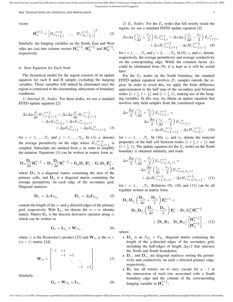
for i = 1, . . . , Nx and j = 2, . . . , Ny . In (9), εx and σx denote,respectively, the average permittivity and average conductivityon the corresponding edge. While the common factor ∆xcould be eliminated from (9), it is kept as it will be usefullater.
For the Ex nodes on the South boundary, the standardFDTD update equation involves Hz samples outside the re-gion. In order to avoid this, we apply the finite differenceapproximation to the half step of the secondary grid betweennodes
(i+ 1
2 , 1 + 12
)and
(i+ 1
2 , 1), making use of the hang-
ing variables. In this way, we obtain an update equation thatinvolves only field samples from the considered region
∆x∆y
2
( εx∆t
+σx2
)Ex|n+1
i+ 12 ,1
=
∆x∆y
2
( εx∆t− σx
2
)Ex|ni+ 1
2 ,1
+ ∆xHz|n+ 1
2
i+ 12 ,1+ 1
2
−∆xHz|n+ 1
2
i+ 12 ,1
, (10)
for i = 1, . . . , Nx. In (10), εx and σx denote the materialproperties of the half cell between nodes
(i+ 1
2 , 1 + 12
)and(
i+ 12 , 1). The update equation for the Ex nodes on the North
boundary is obtained similarly, and reads
∆x∆y
2
( εx∆t
+σx2
)Ex|n+1
i+ 12 ,Ny+1
=
∆x∆y
2
( εx∆t− σx
2
)Ex|ni+ 1
2 ,Ny+1
+ ∆xHz|n+ 1
2
i+ 12 ,Ny+1
−∆xHz|n+ 1
2
i+ 12 ,Ny+ 1
2
, (11)
for i = 1, . . . , Nx. Relations (9), (10) and (11) can be alltogether written in matrix form
DlxDl′y
(Dεx
∆t+
Dσx
2
)En+1x =
DlxDl′y
(Dεx
∆t− Dσx
2
)Enx −DlxG
TyH
n+ 12
z
+[DlxBS DlxBN
] [Hn+ 12
S
Hn+ 1
2
N
], (12)
where:• Dl′y is an NEx × NEx diagonal matrix containing the
length of the y-directed edges of the secondary grid,including the half-edges of length ∆y/2 that intersectthe North and South boundaries;
• Dεx and Dσx are diagonal matrices storing the permit-tivity and conductivity on each x-directed primary edge,respectively;
• BS has all entries set to zero, except for a −1 atthe intersection of each row associated with a Southboundary edge and the column of the correspondinghanging variable in H
n+ 12
S ;

0018-926X (c) 2016 IEEE. Personal use is permitted, but republication/redistribution requires IEEE permission. See http://www.ieee.org/publications_standards/publications/rights/index.html for more information.
This article has been accepted for publication in a future issue of this journal, but has not been fully edited. Content may change prior to final publication. Citation information: DOI 10.1109/TAP.2016.2637867, IEEETransactions on Antennas and Propagation
IEEE TRANSACTIONS ON ANTENNAS AND PROPAGATION 4
• BN is defined similarly to BS , but has a +1 on eachentry associated with an edge of the North boundary.
3) Ey Nodes: The update equations for the Ey nodes arederived with a similar procedure. A standard FDTD updateequation is written for the Ey nodes that fall strictly inside theregion. For the Ey nodes on the West and East boundaries,instead, finite differences are applied on a half grid step,similarly to (10) and (11). This process leads to
DlyDl′x
(Dεy
∆t+
Dσy
2
)En+1y =
DlyDl′x
(Dεy
∆t−
Dσy
2
)Eny + DlyG
TxH
n+ 12
z
+[DlyBW DlyBE
] [Hn+ 12
W
Hn+ 1
2
E
], (13)
where• Dl′x is an NEy × NEy diagonal matrix containing the
length of the x-directed edges of the secondary grid,including the half-edges of length ∆x/2 that intersectthe East and West boundaries;
• Dεy and Dσy are diagonal permittivity and conductivitymatrices associated with the y-directed edges of theprimary grid, respectively;
• BW has all entries set to zero, except for a +1 atthe intersection of each row associated with a Westboundary edge and the column of the correspondinghanging variable in H
n+ 12
W ;• BE is analogous to BW , but has a −1 on each entry
associated with an East boundary edge.
B. Descriptor System Formulation
The update equations from the previous sections form acomplete dynamical model for the electromagnetic field in theregion
(R + F)xn+1 = (R− F)xn + Bun+ 12 , (14a)
yn = LTxn . (14b)
The first equation (14a) is formed by update equations (4),(12) and (13). Equation (14a) updates the state vector
xn =
EnxEny
Hn− 1
2z
, (15)
which consists of all electric and magnetic field samples in theregion, excluding hanging variables. The input vector un+ 1
2
and output vector yn are given by
un+ 12 =
Hn+ 1
2
S
Hn+ 1
2
N
Hn+ 1
2
W
Hn+ 1
2
E
yn =
EnSEnNEnWEnE
. (16)
The input vector contains all hanging variables, i.e. all mag-netic field samples on the region boundaries. The outputvector is made by the E samples at the same nodes, which
are collected into vectors EnS , EnN , EnW and EnE . Outputequation (14b) extracts these values from the state vector xn.The coefficients matrices in (14a) and (14b) read
R =
DlxDl′yDεx
∆t 0 12DlxG
Ty
0 DlyDl′x
Dεy
∆t − 12DlyG
Tx
12GyDlx − 1
2GxDly DADµ
∆t
, (17)
F =
DlxDl′yDσx
2 0 12DlxG
Ty
0 DlyDl′x
Dσy
2 − 12DlyG
Tx
− 12GyDlx
12GxDly 0
, (18)
B =
DlxBS DlxBN 0 00 0 DlyBW DlyBE
0 0 0 0
, (19)
L =
−BS BN 0 00 0 BW −BE
0 0 0 0
. (20)
Equations (14a)-(14b) define an FDTD-like model for a2D lossy, source-free region, with possibly non-uniform per-mittivity, permeability and conductivity. From a control per-spective, this model is a discrete-time descriptor system [25],also known as generalized state-space. From an electricalstandpoint, the model is an impedance-type description of theregion, because it gives the electric field tangential to theboundary in terms of the tangential magnetic field. In [24],a special case of the proposed representation was derived fora lossy region enclosed by PEC boundaries. The proposeddevelopments generalize [24] in two directions:
1) the assumption of a PEC termination is removed. Suit-able input-output variables are introduced in such a waythat model (14a)-(14b) can be connected to other subsys-tems, such as other FDTD grids, boundary conditions,or reduced models;
2) the proposed formulation will allow us to prove, in thenext section, that FDTD equations can be interpreted asa dissipative dynamical system.
III. FDTD AS A DISSIPATIVE DISCRETE-TIME SYSTEM
A. Dissipation Inequality
A discrete-time system like (14a)-(14b) is dissipative whenit satisfies the following condition [26].
Definition 1. Dynamic system (14a)-(14b) is said to bedissipative with supply rate s(yn,un+ 1
2 ) if there exists anonnegative function E(xn) with E(0) = 0, called storagefunction, such that
E(xn+1)− E(xn) ≤ s(yn,un+ 12 ) (21)
for all un+ 12 and all n.
Storage function E(xn) can be interpreted as the energystored in the system at time n. Supply rate s(yn,un+ 1
2 ) can beseen as the energy absorbed by the system from its boundariesbetween time n and n+1. Clearly, only dissipative systems cansatisfy dissipation inequality (21). Indeed, their stored energycan increase between time n and n+ 1 by at most the energy

0018-926X (c) 2016 IEEE. Personal use is permitted, but republication/redistribution requires IEEE permission. See http://www.ieee.org/publications_standards/publications/rights/index.html for more information.
This article has been accepted for publication in a future issue of this journal, but has not been fully edited. Content may change prior to final publication. Citation information: DOI 10.1109/TAP.2016.2637867, IEEETransactions on Antennas and Propagation
IEEE TRANSACTIONS ON ANTENNAS AND PROPAGATION 5
absorbed from the outside world. If this limit is violated, thesystem is considered active, since it can generate energy onits own. For most practical systems, inequality (21) is satisfiedstrictly because of losses.
B. Storage Function and Supply Rate for a FDTD Region
For system (14a)-(14b), we choose as storage function
E(xn) =∆t
2(xn)
TRxn , (22)
and as supply rate
s(yn,un+ 12 ) = ∆t
(yn + yn+1
)T2
LTBun+ 12 . (23)
Before showing that these functions satisfy (21), we investigatetheir physical meaning. Substituting (17) into (22), we get
E(xn) =1
2(Enx)
TDlxDl′yDεxE
nx (24)
+1
2
(Eny)T
DlyDl′xDεyEny
+∆t
2
(Hn− 1
2z
)T[GyDlxE
nx−GxDlyE
ny+DA
Dµ
∆tHn− 1
2z
].
Since the term between square brackets is the right hand sideof (4), we can reduce (24) to
E(xn) =1
2(Enx)
TDlxDl′yDεxE
nx
+1
2
(Eny)T
DlyDl′xDεyEny
+1
2
(Hn− 1
2z
)TDADµH
n+ 12
z . (25)
This expression was proposed in [8] as a discrete approx-imation of the electromagnetic energy stored at time n ina region modelled with the Finite Integration Technique orFDTD. Formula (25) indeed mimics∫
A
[1
2εE2
x(t) +1
2εE2
y(t) +1
2µH2
z (t)
]dA , (26)
the continuous expression for the electromagnetic energy perunit height of a 2D TE mode in a region of area A. The firstterm of (25) is the energy stored in the x component of theelectric field in the region. Indeed, the diagonal matrix DlxDl′yis the area of the half cells around the Ex edges. Similarly,the second and third term in (25) represent the energy storedin the Ey and Hz components, respectively.
We now discuss the physical meaning of supply rate (23).Direct inspection reveals that
LTB =
−∆xINx 0 0 0
0 +∆xINx 0 00 0 +∆yINy 00 0 0 −∆yINy
.(27)
Substituting (27) into (23), we obtain
s(yn,un+ 12 ) = −∆t∆x
(EnS + En+1S )T
2Hn+ 1
2
S
+∆t∆x(EnN + En+1
N )T
2Hn+ 1
2
N +∆t∆y(EnW + En+1
W )T
2Hn+ 1
2
W
−∆t∆y(EnE + En+1
E )T
2Hn+ 1
2
E , (28)
and see that the supply rate is the sum of the energy absorbedby the region from each boundary between time n and n+ 1.Signs in (28) are consistent with the direction of the Poyntingvector on each boundary.
C. Dissipativity Conditions
Using the proposed storage function (22) and supplyrate (23), we can derive simple dissipativity conditions on thecoefficients matrices R, F, B and L in (14a)-(14b).
Theorem 1. If
R = RT > 0 , (29a)F + FT ≥ 0 , (29b)B = LLTB , (29c)
then system (14a)-(14b) is dissipative according to Defini-tion 1, with (22) as storage function and (23) as supply rate.
Proof. Condition (29a) makes storage function (22) nonneg-ative for all xn, as required by Definition 1. Next, we showthat if (29b) and (29c) hold, dissipation inequality (21) willhold as well. Substituting (22) and (23) into (21), we obtain(xn+1
)TRxn+1−(xn)
TRxn−
(yn + yn+1
)TLTBun+ 1
2 ≤ 0 .
This inequality can be rewritten as(xn+1
)TR(xn+1 − xn
)+(xn+1 − xn
)TRxn
−(yn + yn+1
)TLTBun+ 1
2 ≤ 0 (30)
From (14a), we have that
R(xn+1 − xn
)= −F
(xn+1 + xn
)−Bun+ 1
2 (31)
Using (31), the terms R(xn+1 − xn
)and
(xn+1 − xn
)TR
in (30) can be expressed in terms of F
−(xn+1
)TF(xn+1 + xn
)−(xn+1 + xn
)TFTxn
+(xn+1
)TBun+ 1
2 +(un+ 1
2
)TBTxn
− (xn)TLLTBun+ 1
2 −(xn+1
)TLLTBun+ 1
2 ≤ 0 (32)
Under (29c), we can finally rewrite (32) as(xn+1 + xn
)T (F + FT
) (xn+1 + xn
)≥ 0 (33)
which is clearly satisfied if (29b) holds.
We now investigate the physical meaning of the threedissipativity conditions. Equality (29c) can be directly verifiedby combining (27) and (20). This condition holds because theregion inputs and outputs in (16) are sampled at the samenodes, and is reminiscent of a similar relation which holds

0018-926X (c) 2016 IEEE. Personal use is permitted, but republication/redistribution requires IEEE permission. See http://www.ieee.org/publications_standards/publications/rights/index.html for more information.
This article has been accepted for publication in a future issue of this journal, but has not been fully edited. Content may change prior to final publication. Citation information: DOI 10.1109/TAP.2016.2637867, IEEETransactions on Antennas and Propagation
IEEE TRANSACTIONS ON ANTENNAS AND PROPAGATION 6
for linear circuits under the impedance representation [27].Condition (29b) is related to losses, and reads
F + FT =
DlxDl′yDσx 0 0
0 DlyDl′xDσy 00 0 0
≥ 0 . (34)
Since Dlx , Dly , Dl′x and Dl′y are diagonal with positiveelements only, (34) boils down to
Dσx ≥ 0 , (35)Dσy ≥ 0 . (36)
As one may expect, the average conductivity on each primaryedge must be non-negative in a dissipative system. Condi-tion (29a) is the most interesting, and is a generalized CFLcriterion. From (17), we see that R = RT by construction.With the Schur’s complement [28], we can transform (29a)into
DlxDl′yDεx > 0 , (37)
DlyDl′xDεy > 0 , (38)
SST <4
∆t2INHz , (39)
where
S = D− 1
2
A D− 1
2µ
[GyD
12
lxD
− 12
l′yD
− 12
εx −GxD12
lyD
− 12
l′xD
− 12
εy
].
(40)Inequalities (37) and (38) are clearly satisfied by construction.If we denote with sk the singular values of (40), inequality (39)will hold if and only if
∆t <2
sk∀k . (41)
This condition sets an upper bound on the FDTD time step,and is analogous to the generalized CFL constraint derivedin [24] for an FDTD grid terminated on PEC boundaries.From (40), we indeed see that the time step upper limitdepends on grid size, permittivity and permeability. Using atime step which violates (41) has two consequences. First,the discretization of Maxwell’s equations leads to an activediscrete-time model, even if the real physical system haspositive losses everywhere, and should therefore be dissi-pative. The numerical model is thus inconsistent with theactual physics. Second, being able to generate energy onits own, model (14a)-(14b) can lead to divergent transientsimulations. Even when such model is connected to otherdissipative subsystems, its ability to generate energy on itsown can destabilize the whole simulation. The proposed theoryprovides a new, deeper understanding on the root causes ofFDTD instability, and is able to pinpoint which part of anFDTD setup is responsible for it.
D. Relation to CFL Stability Limit
The relation between (41) and the CFL limit can be furtherunderstood if we apply (41) to a single cell. The purposeof (41) is to make storage function (22) non-negative. Asufficient condition for this is to require the energy stored ineach primary cell to be positive. This condition can be derived
by applying (39) to a single primary cell. We consider theprimary cell extending from node (i, j) to node (i+ 1, j+ 1).The coefficient matrices for this special case can be obtainedfrom the formulas in Sec. II by setting Nx = Ny = 1
Dlx = ∆xI2 Dly = ∆yI2 (42)
Dl′x =∆x
2I2 Dl′y =
∆y
2I2 (43)
Gx = Gy =[−1 1
]DA = ∆x∆y (44)
The permeability matrix Dµ = µ|i+ 12 ,j+
12
is the averagepermeability on the secondary edge, while the permittivitymatrices
Dεx =
[εx|i+ 1
2 ,j0
0 εx|i+ 12 ,j+1
]Dεy =
[εy|i,j+ 1
20
0 εy|i+1,j+ 12
](45)
contain the average permittivity on the four primary edges.Substituting (42)-(45) into (39), we obtain
∆t <
[1
2∆x2µ|i+ 12 ,j+
12
(1
εy|i,j+ 12
+1
εy|i+1,j+ 12
)
+1
2∆y2µ|i+ 12 ,j+
12
(1
εx|i+ 12 ,j
+1
εx|i+ 12 ,j+1
)]− 12
, (46)
which is a generalized CFL condition. For a uniform mediumwith permittivity ε and permeability µ, (46) reduces to
∆t <1√
1εµ
√1
∆x2 + 1∆y2
, (47)
the CFL limit of 2D FDTD. This derivation confirms that (29a)is a generalized CFL condition, here reinterpreted in thecontext of dissipation.
E. Application to Stability Analysis
The proposed dissipation theory can be effectively usedto investigate and enforce the stability of FDTD algorithms.Most FDTD setups consist of an interconnection of FDTDsubsystems. In the simplest scenario, a uniform FDTD gridis connected to some boundary conditions. In most advancedscenarios, one may want to couple a main FDTD grid torefined grids, reduced models, lumped elements, or modelsfrom other numerical techniques, such as finite elements,integral equations or ray tracing.
Ensuring stability of these hybrid schemes can be verychallenging, since stability is a property of the overall scheme,rather than of its individual subsystems. By invoking the con-cept of dissipation, we can instead achieve stability in an easyand modular way. Each part is seen as an FDTD subsystemand required to satisfy dissipativity conditions (29a)-(29c).Since the connection of dissipative systems is dissipative byconstruction [17], the overall method will be guaranteed to bestable. The proposed theoretical framework generalizes the so-called energy method [8], and has numerous advantages overthe state of the art:
1) non-uniform problems can be handled, unlike in the vonNeumann analysis [1];

0018-926X (c) 2016 IEEE. Personal use is permitted, but republication/redistribution requires IEEE permission. See http://www.ieee.org/publications_standards/publications/rights/index.html for more information.
This article has been accepted for publication in a future issue of this journal, but has not been fully edited. Content may change prior to final publication. Citation information: DOI 10.1109/TAP.2016.2637867, IEEETransactions on Antennas and Propagation
IEEE TRANSACTIONS ON ANTENNAS AND PROPAGATION 7
2) stability conditions can be given on each subsystemseparately, unlike in the iteration method [2], whichrequires the analysis of the iteration matrix of the wholescheme. This makes stability analysis modular and thussimpler;
3) once some given FDTD models have been proven dis-sipative, they can be arbitrarily interconnected withouthaving to carry out further stability proofs. With theiteration method, when a single part of a coupled schemechanges, the whole proof must be revised;
4) the CFL limit of the resulting scheme can be easilydetermined by applying (39) to each subsystem andtaking the most restrictive CFL limit;
5) the stability framework is intuitive, since it is based onthe fundamental physical concept of energy dissipation.
IV. APPLICATION: STABLE FDTD SUBGRIDDING
We demonstrate the usefulness of the proposed theory byderiving a subgridding algorithm which is stable by con-struction, easy to implement and supports an arbitrary gridrefinement ratio. The goal is to derive stable update equationsfor a setup where one or more fine grids are embedded ina main coarse grid. Without loss of generality, we considerthe case where a coarse grid with cell size ∆x × ∆y hostsa single fine grid with cell size ∆x/r ×∆y/r, where r ≥ 2is an arbitrary integer. The algorithm will ultimately consistof conventional FDTD equations to update the fields that fallstrictly inside the two grids, and a special update equation toupdate the fields on the edges shared by the coarse and finegrids. To derive the method, it is sufficient to consider theinterface between a single coarse cell and the correspondingfine cells, as shown in Fig. 2. In the figure a virtual gap hasbeen opened between the two grids for clarity. Without loss ofgenerality, we consider a refinement in the positive x direction.The other three cases can be derived in the same way. Thecoarse cell under consideration is centered at node (i+ 1
2 , j−12 )
and the corresponding fine cells at nodes (ı + 12 , + 1
2 ), ... ,(ı+ r − 1
2 , + 12 ), where coordinates (ı, ) correspond to the
same physical location as (i, j) in the coarse grid. Superscript“ˆ” denotes variables related to the fine grid.
A subgridding algorithm can be interpreted as the result ofthe connection of three subsystems, as shown in Fig. 3. Twoof those subsystems are the coarse and fine grids. The thirdsubsystem represents the interpolation rule which is used torelate the fields on the boundaries of the two grids, that aresampled with different resolution.
A. State Equations for the Coarse and Fine Cells on theBoundary
For the coarse and fine grids, we adopt the formulation ofSec. II, introducing hanging variables on the two boundaries tobe connected. The purpose of hanging variables is to facilitatethe coupling of the two meshes and the proof of stability.These extra variables will be eliminated when deriving thefinal update equation for the fields at the interface. On theNorth boundary of the coarse cell, we introduce the hangingvariable
Hn+ 1
2
N = Hz|n+ 1
2
i+ 12 ,j. (48)
Hz|ı+ 12 ,+
12
Hz|ı+ 32 ,+
12
Hz|ı+ 12, Hz|ı+ 3
2,
Hz|i+ 12,j− 1
2
Hz|i+ 12,j
Ex|ı+ 12, Ex|ı+ 3
2,
Ex|i+ 12,j
(ı, )
(i, j)
x
y
z
∆xr
∆yr
Fig. 2. Subgridding scenario considered in Sec. IV for the case of r = 2.For clarity, a virtual gap has been inserted between the two grids.
Fine mesh
Coarse mesh
Interpolation rule
Hz|i+ 12,j Ex|i+ 1
2,j
Hz|ı+ 12, Ex|ı+ 3
2, Hz|ı+ 3
2, Ex|ı+ 1
2,
Fig. 3. Interpretation of the subgridding method as the connection ofthree dynamical systems, representing the coarse grid, the fine grid, and theinterpolation rule.
Similarly, on the South boundary of the fine cells we introducethe hanging variables
Hn+ 1
2
S =[Hz|
n+ 12
ı+ 12 ,
. . . Hz|n+ 1
2
ı+r− 12 ,
]T, (49)
as shown in Fig. 2.From (11), we obtain the following state equation for EnN ,
the coarsely-sampled electric field at the interface
∆y
2
( εx∆t
+σx2
)En+1N =
∆y
2
( εx∆t− σx
2
)EnN +H
n+ 12
N −Hn+ 12
j− 12
, (50)
where
Hn+ 1
2
j− 12
= Hz|n+ 1
2
i+ 12 ,j−
12
, EnN = Ex|ni+ 12 ,j, (51)
and εx and σx are the permittivity and conductivity on theprimary edge of the coarse cell below the interface. Similarly,the state equation for the r fine cells can be obtained from (10)
∆y
2r
(Dεx
∆t+
Dσx
2
)En+1S =
∆y
2r
(Dεx
∆t− Dσx
2
)EnS + H
n+ 12
+ 12
− Hn+ 1
2
S , (52)
where
Hn+ 1
2
+ 12
=[Hz|
n+ 12
ı+ 12 ,+
12
. . . Hz|n+ 1
2
ı+r− 12 ,+
12
]T, (53)
EnS =[Ex|nı+ 1
2 ,. . . Ex|nı+r− 1
2 ,
]T, (54)

0018-926X (c) 2016 IEEE. Personal use is permitted, but republication/redistribution requires IEEE permission. See http://www.ieee.org/publications_standards/publications/rights/index.html for more information.
This article has been accepted for publication in a future issue of this journal, but has not been fully edited. Content may change prior to final publication. Citation information: DOI 10.1109/TAP.2016.2637867, IEEETransactions on Antennas and Propagation
IEEE TRANSACTIONS ON ANTENNAS AND PROPAGATION 8
and Dεx and Dσx are r × r diagonal matrices containing thevalues of permittivity and conductivity above the interface forthe South edges where the fine Ex fields are sampled.
B. Interpolation Rule
The coarse and fine grids are connected by imposing asuitable relation between the electric and magnetic sampleson the two boundaries. For the electric field, we impose
EnS = TEnN ∀n , (55)
where T is an r × 1 matrix of ones. Condition (55) makesthe coarsely- and finely-sampled E fields equal at all times, asone may expect from the boundary condition on the electricfield tangential to an interface. On the magnetic fields at theboundary, we impose a reciprocal constraint similar to the oneused in [29], but applied right at interface
Hn+ 1
2
N =1
rTT H
n+ 12
S ∀n . (56)
This condition sets the coarsely-sampled magnetic field tobe equal to the spatial average of the finely-sampled mag-netic field. We will see in Sec. IV-D that the reciprocitybetween (55) and (56) is required to ensure stability.
C. Explicit Update Equation for the Interface
Interpolation conditions (55) and (56) can now be usedto combine (50) and (52) in order to derive an explicitupdate equation for the fields at the coarse-fine interface, andeliminate hanging variables.
Substituting (55) into (52), and multiplying the obtainedequation by TT /r on the left yields
∆y
2r
(TT DεxT
r∆t+
TT DσxT
2r
)En+1N =
∆y
2r
(TT DεxT
r∆t− TT DσxT
2r
)EnN
+TT H
n+ 12
+ 12
r−
TT Hn+ 1
2
S
r. (57)
Equation (57) can now be added to (50), yielding
∆y
2
(εx + εx
r
∆t+σx + σx
r
2
)En+1N =
∆y
2
(εx + εx
r
∆t−σx + σx
r
2
)EnN
+Hn+ 1
2
N −Hn+ 12
j− 12
+TT H
n+ 12
+ 12
r−
TT Hn+ 1
2
S
r, (58)
where
εx =1
rTT DεxT , σx =
1
rTT DσxT . (59)
Because of (56), the hanging variable Hn+ 12
N in (58) can beeliminated, obtaining
∆y
2
(εx + εx
r
∆t+σx + σx
r
2
)En+1N =
∆y
2
(εx + εx
r
∆t−σx + σx
r
2
)EnN −H
n+ 12
j− 12
+TT H
n+ 12
+ 12
r.
(60)
Rearranging (60), we get the following explicit update equa-tion for EnN in terms of the neighboring magnetic fields
En+1N =
(εx + εx
r
∆t+σx + σx
r
2
)−1(εx + εx
r
∆t−σx + σx
r
2
)EnN
+2
∆y
(εx + εx
r
∆t+σx + σx
r
2
)−1TT H
n+ 12
+ 12
r−Hn+ 1
2
j− 12
.
(61)
The fine interface electric fields are then updated using (55).It should be noted that, when r = 1, equation (61) reduces tothe standard FDTD update equation.
The overall subgridding algorithm can be summarized asfollows:
1) Calculate the magnetic field samples everywhere at timen+ 1
2 using conventional FDTD update equations.2) Use standard FDTD update equations to compute the E
fields at time n+ 1 on the edges that are strictly insidethe coarse and fine grids.
3) Compute En+1N , the coarsely-sampled electric field at
the interface, using (61).4) Compute the finely-sampled En+1
S fields at the interfaceusing (55).
The proposed method is thus simple to implement, since itconsists of conventional FDTD update equations inside thetwo meshes and a modified update equation for the edges atthe interface. In comparison to previous subgridding methods,we avoid non-rectangular cells [6], finite element concepts [20]and Withney forms [21], [22]. Corners are natively handled,without any need for special treatment [5] nor L-shapedcells [6]. The computational overhead of the proposed schemeis minimal, since the coefficients in (61) can be pre-computedonce before runtime. Any integer refinement factor r is sup-ported, both even and odd. Finally, we remark that, in Sec. II,the FDTD update equations have been given in matrix formin order to reveal their dissipative nature. This form does nothave to be used in practical implementations, which can useconventional “for” loops or vectorized operations.
D. Proof of Stability
The dissipation theory proposed in Sec. III makes it straight-forward to analyse the stability of the proposed method. For atimestep below the CFL limit of the fine grid, the subsystemsassociated to both the coarse and the fine mesh are dissipative,as discussed in Sec. III. In order to guarantee overall stability,we need to only ensure the dissipativity of the interpolation

0018-926X (c) 2016 IEEE. Personal use is permitted, but republication/redistribution requires IEEE permission. See http://www.ieee.org/publications_standards/publications/rights/index.html for more information.
This article has been accepted for publication in a future issue of this journal, but has not been fully edited. Content may change prior to final publication. Citation information: DOI 10.1109/TAP.2016.2637867, IEEETransactions on Antennas and Propagation
IEEE TRANSACTIONS ON ANTENNAS AND PROPAGATION 9
rule which connects them. Analogously to (28), the supplyrate for the interpolation subsystem reads
s(yn,un+ 12 ) = −∆t∆x
EnN + En+1N
2Hn+ 1
2
N
+ ∆t∆x
r
(EnS + En+1S )T
2Hn+ 1
2
S . (62)
Substituting (55) and (56) into (62), we have
s(yn,un+ 12 ) =
∆t∆x(EnN + En+1
N )T
2
(TT H
n+ 12
S
r−Hn+ 1
2
N
)= 0 . (63)
Therefore, the proposed interpolation rule corresponds to alossless system that does not dissipate nor generate any energy.Physically, this result makes sense, since the connection sys-tem corresponds to an infinitely thin region where no energydissipation takes place. In conclusion, since the proposedsubgridding method can be seen as the connection of threedissipative systems, it is overall dissipative, and thus stable,for any timestep ∆t below the CFL limit of the fine mesh.
V. NUMERICAL EXAMPLES
Several numerical tests were performed to verify the pro-posed theory and test the subgridding method. All algorithmswere implemented in MATLAB using vectorized operationsfor efficiency reasons. Computations were performed on a3.40 GHz Intel i7 CPU with 16 GB of memory. Somepreliminary results were presented in [30].
A. Stability Verification
Stability was verified by simulating an empty cavity withperfect electric conductor (PEC) walls with a centrally placedsubgridding region for 106 time steps. A refinement factorr = 4 was used. The layout of the simulation is shown inFig. 4. The cavity was excited using a modulated Gaussianmagnetic current source with central frequency of 3.75 GHzand half-width at half-maximum of 0.74 GHz. Magnetic fieldwas recorded at a probe placed inside the cavity. The time stepwas set at 0.99 times the CFL limit of the fine grid.
The magnetic field at the probe in Fig. 5 shows that noinstability occurred after 106 time steps. Stable behavior aftersuch a large number of time steps verifies the correctness ofthe proposed theory, especially since no lossy materials werepresent to dissipate any spurious energy artificially created bythe algorithm.
B. Material Traverse Test
The ability of the proposed method to produce meaningfulresults when objects traverse the subgridding interface wastested using the setup in Fig. 6. A 16 × 16 mm block ofmaterial was simulated for three different placements of thesubgridding region: enclosing, traversing and away from theblock. The test was done for copper and for a lossy dielectricwith conductivity of 5 S/m and relative permittivity of 2.As a reference, uniformly discretized all-coarse and all-fine
PEC
Source
Probe
∆x = ∆x/4∆y = ∆y/4
∆x = 1 mm∆y = 2 mm
x
y
z
60 mm
40m
m
40 mm
20m
m
Fig. 4. Layout of the PEC cavity considered in Sec. V-A.
0 2 4 6 8 10
x 105
−0.5
0
0.5
Timestep
Hz (
A/m
)
Fig. 5. Magnetic field at the probe for the the empty cavity with subgriddingof Sec. V-A, computed for 106 time steps.
simulations were performed at the fine time step, in additionto the subgridding simulations. The coarse mesh resolutionwas set to ∆x = ∆y = 1 mm, and a refinement factor ofr = 5 was used. The simulation region was terminated ona 15 mm-thick perfectly matched layer (PML). A modulatedGaussian magnetic current excitation was used, with 15.0 GHzcentral frequency and 8.82 GHz half-width at half-maximumbandwidth. In all test cases, a time step of 0.467 ps was used.This value corresponds to 0.99 times the CFL limit of thefine grid. The magnetic field waveforms at the probe recordedin the different subgridding scenarios are shown in Fig. 7,and are in excellent agreement among each other. This resultconfirms that the proposed subgridding method can properlyhandle material traverse, for both very good conductors andfor lossy dielectrics.
C. Reflection Test
In order to investigate the accuracy of the proposed scheme,we looked at waveguide reflections from the scatterer shownin Fig. 8, which consisted of four copper rods with 1 mmradius. We have also investigated the reflections from thesubgridding interface, in order to assess the quality of thesubgridding scheme. The coarse cell was chosen to be 1 mm,which was 1
10 of the minimum wavelength of interest thatcorresponded to 30.0 GHz. The fields of the incident wavewere computed by running a reference simulation withoutthe scatterer and without subgridding. The reflected field wasfound by subtracting the incident field from the total field insimulations with the scatterer. A 15 mm-thick PML boundarywas chosen to terminate the two sides of the waveguide. Thetime step in the subgridding runs was set to 0.99 times the CFL

0018-926X (c) 2016 IEEE. Personal use is permitted, but republication/redistribution requires IEEE permission. See http://www.ieee.org/publications_standards/publications/rights/index.html for more information.
This article has been accepted for publication in a future issue of this journal, but has not been fully edited. Content may change prior to final publication. Citation information: DOI 10.1109/TAP.2016.2637867, IEEETransactions on Antennas and Propagation
IEEE TRANSACTIONS ON ANTENNAS AND PROPAGATION 10
PML
Source
Probe
subgridssubgrids
x
y
z
Fig. 6. Layout used for the material traverse test of Sec. V-B. The dashed linesshow the different placements of the subgridded region that were considered.
−0.02
0
0.02
Hz (
A/m
)
Lossy dielectric
0.2 0.25 0.3 0.35
−0.02
0
0.02
Time (ns)
Hz (
A/m
)
Copper
Fig. 7. Magnetic field at the probe for the material traverse test of Sec. V-B,with the subgridding region enclosing the object ( ), traversing theobject ( ) or outside the object ( ). Waveforms from the all-coarse ( � ) and all-fine ( ) simulations are also shown.
limit of the refined region. Uniformly discretized simulationswere run at 0.99 times the CFL limit of the correspondingmesh.
The resulting reflections are shown in Fig. 9 for the sub-gridding case with different refinement ratios, as well as thereference run with a full refinement of the mesh by a factor of6. The simulation times are shown in Table I. It can be seenthat the local refinement of the grid around the scatterer withthe proposed subgridding method can improve the accuracysubstantially compared to the coarse grid run. The largerchoice of refinement ratio makes the solution very close tothe reference all-fine solution. Moreover, very good speedup- almost by a factor of 11 - is achieved even for the highestgrid refinement of r = 6. The reflections from subgriddinginterface are significantly lower than those from the scatterer,further demonstrating the accuracy of the proposed method.
D. Human Exposure Test
The final test is inspired by a human exposure study,where one wants to assess the exposure to electromagneticradiation of human tissues caused by an antenna. This problem
PML PML
8×8 mm
Jy currentProbes
PEC
x
y
z
66 mm
40m
m
∆x = 1 mm∆y = 1 mm
20 mm
Scatterer
2 mm
2 mm
Fig. 8. Layout of the four-rod reflection test in Sec. V-C. The dashed lineshows the location of the subgrid.
−35
−30
−25
−20
−15
−10
−5With scatterer
|S1
1| (
dB
)
0 5 10 15 20 25
−100
−80
−60
−40
Frequency (GHz)
|S1
1| (
dB
)
Sub−grid interface only
Fig. 9. Reflected power with respect to the incident for the example ofSec. V-C. Top panel: reflections from the four-rod scatterer for an all-coarsemesh ( � ), an all-fine mesh with r = 6 ( ), and for the proposedsubgridding method for r = 2 ( ), r = 4 ( ) and r = 6 ( ).Bottom panel: reflections from the subgrid interface only.
is intrinsically multiscale, due to the fine tissues present inthe human body. The chosen setup is shown in Fig. 10. Atransverse cross-section of the head of the Ella model fromIT’IS Virtual Population V1.x [31] was used to assign thematerial properties [32] to the FDTD cells. A 900 MHz sourcewas placed approximately 3 meters away from the humanhead. The simulation region was terminated with a 20 cm-thick PML. The reference (fine) resolution in the tissues wasset to 2 mm, based on the mesh size chosen by [33] in aradiation exposure study at that frequency. Specific absorptionrate, or SAR, was evaluated according to the formula in [34],which was used as follows for sinusoidal excitation
SAR =σ(E2
xp + E2yp)
2ρ, (64)
where subscript “p” denotes the peak absolute value of a fieldcomponent and ρ corresponds to tissue density. SAR wascalculated for each primary cell. The values of the electricfield components at the primary cell centers were found by

0018-926X (c) 2016 IEEE. Personal use is permitted, but republication/redistribution requires IEEE permission. See http://www.ieee.org/publications_standards/publications/rights/index.html for more information.
This article has been accepted for publication in a future issue of this journal, but has not been fully edited. Content may change prior to final publication. Citation information: DOI 10.1109/TAP.2016.2637867, IEEETransactions on Antennas and Propagation
IEEE TRANSACTIONS ON ANTENNAS AND PROPAGATION 11
Table ISIMULATION TIME FOR THE FOUR-ROD SCATTERING TEST IN SEC. V-C.
Method Simulation time (s)All-fine (r = 6) 427.4
All-coarse 3.2Subgridding (r = 2) 10.7Subgridding (r = 4) 23.3Subgridding (r = 6) 39.5
PML
Sourcesubgrid
Headslice
x
y
z
4.01m
3.05
m
Fig. 10. Layout of the simulation in Sec. V-D with human head cross-sectionplaced approximately 3 m away from a point source.
averaging the nearest known samples at the cell edges. Thepeak values of the fields were found for the time interval from25.6 ns to 26.8 ns, which gave the wave sufficient time to reachthe head and penetrate inside it prior to the SAR computation.
For the coarse mesh, a resolution of ∆x = ∆y = 1 cmwas used, which corresponds to 1
33.3 of the wavelength at900 MHz. The proposed subgridding method was run for arefinement ratio of r = 5. An all-fine mesh with a resolutionof 2 mm everywhere was taken as reference. The volumetricintegral of SAR over the tissues was used as an accuracymetric ∑
i
∑j
SAR|i+ 12 ,j+
12∆x∆y , (65)
where ∆x and ∆y are FDTD cell dimensions in the tissues.A time step of 4.67 ps was chosen for the all-fine simulationand for the subgridding simulation. This value corresponds to0.99 times the CFL limit of the fine mesh. The coarse gridcase was run with ∆t = 23.11 ps.
The resulting SAR maps are shown in Fig. 11. Table IIshows simulation times and percent error in the total SARwith respect to the all-fine simulation. The results show thatwith subgridding a speedup of 46X can be obtained with only3.1% loss in accuracy. No noticeable difference can be seenon the SAR maps in Fig. 11 between the subgridding andall-fine simulations. When, instead, the coarse resolution waschosen for the entire grid, the head tissues were not sufficientlyresolved and the integral SAR differed from the reference by59.5%, showing the necessity of local grid refinement.
VI. CONCLUSION
This paper proposed a dissipative systems theory for FDTD,which can be conveniently used to analyse the stability of bothsimple and advanced FDTD schemes. The FDTD equationsfor a two-dimensional region are written in the form of adynamical system that has the magnetic field on the boundaryas input, and the electric field on the boundary as output.Suitable expressions for the energy stored in the region and
Table IIERROR IN THE INTEGRAL OF SAR AND SIMULATION TIME FOR THE
EXAMPLE OF SEC. V-D.
Method Error in SAR integral Simulation time (s)All-fine Not applicable 1596.4
All-coarse 59.5% 6.9Subgridding -3.1% 34.5
All-fine Subgridding All-coarse
Fig. 11. SAR maps for the test of Sec. V-D with all-fine, all-coarse meshand with the proposed subgridding method for r = 5.
the energy absorbed from the boundaries are presented, andused to show that, under a generalized Courant-Friedrichs-Lewy condition, FDTD equations can be seen as a dissipativesystem. The theory provides a new, powerful framework tomake FDTD stability analysis simpler and modular. Stabilityconditions can indeed be given on the individual components(e.g. boundary conditions, meshes, thin-wire models) ratherthan on the whole coupled FDTD setup. The theory is intuitivesince rooted on the familiar concept of energy dissipation,and sheds new light on the root mechanisms behind FDTDinstability. As an example of application, a simple yet effectivesubgridding algorithm is derived, with straightforward stabilityproof. The proposed algorithm allows material traverse, issimpler to implement than existing solutions, and supports anarbitrary grid refinement ratio. Numerical results confirm itsstability and accuracy. Speedups of up to 46X were observedwith only 3.1% error with respect to standard FDTD.
REFERENCES
[1] A. Taflove and S. C. Hagness, Computational electrodynamics. Artechhouse, 2005.
[2] S. D. Gedney, Introduction to the Finite-Difference Time-Domain(FDTD) Method for Electromagnetics, 1st ed. San Rafael, CA: Morgan& Claypool Publishers, 2011.
[3] K. Yee, “Numerical solution of initial boundary value problems involv-ing Maxwell’s equations in isotropic media,” IEEE Trans. AntennasPropag., vol. 14, no. 3, pp. 302–307, 1966.
[4] M. Okoniewski, E. Okoniewska, and M. Stuchly, “Three-dimensionalsubgridding algorithm for FDTD,” IEEE Trans. Antennas Propag.,vol. 45, no. 3, pp. 422–429, 1997.
[5] P. Thoma and T. Weiland, “A consistent subgridding scheme for thefinite difference time domain method,” Int. J. Numer. Model El., vol. 9,no. 5, pp. 359–374, 1996.
[6] K. Xiao, D. J. Pommerenke, and J. L. Drewniak, “A three-dimensionalFDTD subgridding algorithm with separated temporal and spatial in-terfaces and related stability analysis,” IEEE Trans. Antennas Propag.,vol. 55, no. 7, pp. 1981–1990, 2007.
[7] W. Sui, D. A. Christensen, and C. H. Durney, “Extending the two-dimensional FDTD method to hybrid electromagnetic systems withactive and passive lumped elements,” IEEE Trans. Microw. TheoryTechn., vol. 40, no. 4, pp. 724–730, 1992.
[8] F. Edelvik, R. Schuhmann, and T. Weiland, “A general stability analysisof FIT/FDTD applied to lossy dielectrics and lumped elements,” Inter-national Journal of Numerical Modelling: Electronic Networks, Devicesand Fields, vol. 17, no. 4, pp. 407–419, 2004.

0018-926X (c) 2016 IEEE. Personal use is permitted, but republication/redistribution requires IEEE permission. See http://www.ieee.org/publications_standards/publications/rights/index.html for more information.
This article has been accepted for publication in a future issue of this journal, but has not been fully edited. Content may change prior to final publication. Citation information: DOI 10.1109/TAP.2016.2637867, IEEETransactions on Antennas and Propagation
IEEE TRANSACTIONS ON ANTENNAS AND PROPAGATION 12
[9] B. Denecker, F. Olyslager, L. Knockaert, and D. De Zutter, “Generationof FDTD subcell equations by means of reduced order modeling,” IEEETrans. Antennas Propag., vol. 51, no. 8, pp. 1806–1817, 2003.
[10] X. Li, C. D. Sarris, and P. Triverio, “Structure-Preserving Reduction ofFinite-Difference Time-Domain Equations with Controllable StabilityBeyond the CFL Limit,” IEEE Trans. Microw. Theory Techn., vol. 62,no. 12, pp. 3228–3238, 2014.
[11] X. Li and P. Triverio, “Stable FDTD Simulations with Subgridding at theTime Step of the Coarse Grid: a Model Order Reduction Approach,” inIEEE MTT-S Int. Conf. on Numerical Electromagnetic and MultiphysicsModeling and Optimization, Ottawa, Canada, August 11–14 2015.
[12] J.-F. Lee, R. Lee, and A. Cangellaris, “Time-domain finite-elementmethods,” IEEE Trans. Antennas Propag., vol. 45, no. 3, pp. 430–442,1997.
[13] A. R. Bretones, R. Mittra, and R. G. Martın, “A hybrid techniquecombining the method of moments in the time domain and FDTD,”IEEE Microw. Guided Wave Lett., vol. 8, no. 8, pp. 281–283, 1998.
[14] Y. Wang, S. Safavi-Naeini, and S. K. Chaudhuri, “A hybrid techniquebased on combining ray tracing and FDTD methods for site-specificmodeling of indoor radio wave propagation,” IEEE Trans. AntennasPropag., vol. 48, no. 5, pp. 743–754, 2000.
[15] T. Namiki, “A new FDTD algorithm based on alternating-directionimplicit method,” IEEE Microw. Wireless Compon. Lett., vol. 47, no. 10,pp. 2003–2007, 1999.
[16] F. Zheng, Z. Chen, and J. Zhang, “A Finite-Difference time-domainmethod without the Courant stability conditions,” IEEE MicrowaveGuided Wave Lett., vol. 9, no. 11, pp. 441–443, Nov 1999.
[17] P. Triverio, S. Grivet-Talocia, M. S. Nakhla, F. Canavero, R. Achar,“Stability, causality, and passivity in electrical interconnect models,”IEEE Trans. Adv. Packag., vol. 30, no. 4, pp. 795–808, 2007.
[18] J. C. Willems, “Dissipative dynamical systems part i: General theory,”Archive for rational mechanics and analysis, vol. 45, no. 5, pp. 321–351,1972.
[19] Y. Wang, S. Langdon, and C. Penney, “Analysis of accuracy and stabilityof FDTD subgridding schemes,” in 2010 European Microwave Conf.,2010, pp. 1297–1300.
[20] F. Collino, T. Fouquet, and P. Joly, “Conservative space-time meshrefinement methods for the FDTD solution of Maxwell’s equations,”J. Comput. Phys., vol. 211, no. 1, pp. 9–35, 2006.
[21] R. A. Chilton and R. Lee, “Conservative and provably stable FDTDsubgridding,” IEEE Trans. Antennas Propag., vol. 55, no. 9, pp. 2537–2549, 2007.
[22] N. V. Venkatarayalu, R. Lee, Y.-B. Gan, and L.-W. Li, “A stable FDTDsubgridding method based on finite element formulation with hangingvariables,” IEEE Trans. Antennas Propag., vol. 55, no. 3, pp. 907–915,2007.
[23] J. Brewer, “Kronecker products and matrix calculus in system theory,”IEEE Trans. Circuits Syst., vol. 25, no. 9, pp. 772–781, 1978.
[24] B. Denecker, F. Olyslager, L. Knockaert, and D. De Zutter, “A new state-space-based algorithm to assess the stability of the Finite-Differencetime-domain method for 3D finite inhomogeneous problems,” AEU-Int.J. Electron. C, vol. 58, no. 5, pp. 339 – 348, 2004.
[25] L. Dai, Singular control systems. Springer, 1989.[26] C. Byrnes and W. Lin, “Losslessness, feedback equivalence, and the
global stabilization of discrete-time nonlinear systems,” IEEE Trans.Autom. Control, vol. 39, no. 1, pp. 83–98, 1994.
[27] S. Grivet-Talocia and B. Gustavsen, Passive Macromodeling: Theoryand Applications. Hoboken, NJ: Wiley, 2015.
[28] S. Boyd, L. El Ghaoui, E. Feron, and V. Balakrishnan, Linear MatrixInequalities in System and Control Theory, ser. Studies in AppliedMathematics. SIAM, 1994, vol. 15.
[29] L. Kulas and M. Mrozowski, “Reciprocity principle for stable subgrid-ding in the finite difference time domain method,” in EUROCON, 2007.The International Conference on “Computer as a Tool”, Sept 2007, pp.106–111.
[30] X. Zhang, F. Bekmambetova, and P. Triverio, “A Dissipative ControlApproach to Ensure Stability in Advanced FDTD Schemes,” in 2016USNC-URSI National Radio Science meeting, Fajardo, Puerto Rico, June26 - July 1 2016.
[31] A. Christ et al., “The Virtual Family - Development of surface-basedanatomical models of two adults and two children for dosimetricsimulations,” Physics in Medicine and Biology, vol. 55, no. 2, pp. N23–N38, 2010.
[32] IT’IS Foundation, “Overview - Database of Tissue Properties.”[Online]. Available: http://www.itis.ethz.ch/virtual-population/tissue-properties/overview/ [Aug. 19, 2015].
[33] S. Kuhn et al., “MMF/GSMA phase 2: scientific basis for base stationexposure compliance standards,” IT’IS Foundation, Tech. Rep. 21, June2009.
[34] D. A. Sanchez-Hernandez, High Frequency Electromagnetic Dosimetry.Boston, MA: Artech House, 2009.
Fadime Bekmambetova (S’16) completed theB.A.Sc degree in Engineering Science at the Uni-versity of Toronto in 2016 and is currently pursuingthe M.A.Sc degree at the same university. In 2016,she received the Best Student Paper Award at the25th IEEE Conference on Electronic Packages andSystems.
Xinyue Zhang (S’16) received her B.Sc. and M.S.degree in electrical engineering from Harbin Instituteof Technology, Harbin, China, in 2012 and 2014, re-spectively. Currently, she is working towards a Ph.D.degree in electrical engineering from the Universityof Toronto, Toronto, ON, Canada. Her research inter-ests include computational electromagnetics, modelorder reduction, and wireless communication. Shereceived the Best Paper Award of 6th InternationalICST Conference on Communications and Network-ing, 2011.
Piero Triverio (S’06 – M’09 – SM’16) received theM.Sc. and Ph.D. degrees in Electronic Engineeringfrom Politecnico di Torino, Italy in 2005 and 2009,respectively. He is an Assistant Professor with theDepartment of Electrical and Computer Engineeringat the University of Toronto, where he holds theCanada Research Chair in Modeling of ElectricalInterconnects. His research interests include signalintegrity, electromagnetic compatibility, and modelorder reduction. He received several internationalawards, including the 2007 Best Paper Award of the
IEEE Transactions on Advanced Packaging, the EuMIC Young Engineer Prizeat the 13th European Microwave Week, and the Best Paper Award at the IEEE17th Topical Meeting on Electrical Performance of Electronic Packaging.