Embed Size (px)
Citation preview

IEEE Std 802.1AB™- 2005
802.1ABTM
I E E E Standard forLocal and metropolitan area networks
Station and Media Access ControlConnectivity Discovery
3 Park Avenue, New York, NY 10016-5997, USA
IEEE Computer Society
Sponsored by theLAN/MAN Standards Committee
6 May 2005
Print: SH95332PDF: SS95332

Recognized as anAmerican National Standard (ANSI)
The Institute of Electrical and Electronics Engineers, Inc.3 Park Avenue, New York, NY 10016-5997, USA
Copyright © 2005 by the Institute of Electrical and Electronics Engineers, Inc.All rights reserved. Published 6 May 2005. Printed in the United States of America.
IEEE and 802 are registered trademarks in the U.S. Patent & Trademark Office, owned by the Institute of Electrical andElectronics Engineers, Incorporated.
Print: ISBN 0-7381-4687-0 SH95332PDF: ISBN 0-7381-4688-9 SS95332
No part of this publication may be reproduced in any form, in an electronic retrieval system or otherwise, without the priorwritten permission of the publisher.
IEEE Std 802.1AB™-2005
IEEE Standard for Local and metropolitan area networks
Station and Media Access Control Connectivity Discovery
Sponsor
LAN/MAN Standards Committeeof theIEEE Computer Society
Approved 28 June 2005
American National Standards Institute
Approved 20 March 2005
IEEE-SA Standards Board
Abstract: This document defines a protocol and a set of managed objects that can be used fordiscovering the physical topology from adjacent stations in IEEE 802® LANs.Keywords: link layer discovery protocol, management information base, topology discovery,topology information.
IEEE Standards documents are developed within the IEEE Societies and the Standards Coordinating Committees of theIEEE Standards Association (IEEE-SA) Standards Board. The IEEE develops its standards through a consensusdevelopment process, approved by the American National Standards Institute, which brings together volunteersrepresenting varied viewpoints and interests to achieve the final product. Volunteers are not necessarily members of theInstitute and serve without compensation. While the IEEE administers the process and establishes rules to promote fairnessin the consensus development process, the IEEE does not independently evaluate, test, or verify the accuracy of any of theinformation contained in its standards.
Use of an IEEE Standard is wholly voluntary. The IEEE disclaims liability for any personal injury, property or otherdamage, of any nature whatsoever, whether special, indirect, consequential, or compensatory, directly or indirectly resultingfrom the publication, use of, or reliance upon this, or any other IEEE Standard document.
The IEEE does not warrant or represent the accuracy or content of the material contained herein, and expressly disclaimsany express or implied warranty, including any implied warranty of merchantability or fitness for a specific purpose, or thatthe use of the material contained herein is free from patent infringement. IEEE Standards documents are supplied “AS IS.”
The existence of an IEEE Standard does not imply that there are no other ways to produce, test, measure, purchase, market,or provide other goods and services related to the scope of the IEEE Standard. Furthermore, the viewpoint expressed at thetime a standard is approved and issued is subject to change brought about through developments in the state of the art andcomments received from users of the standard. Every IEEE Standard is subjected to review at least every five years forrevision or reaffirmation. When a document is more than five years old and has not been reaffirmed, it is reasonable toconclude that its contents, although still of some value, do not wholly reflect the present state of the art. Users are cautionedto check to determine that they have the latest edition of any IEEE Standard.
In publishing and making this document available, the IEEE is not suggesting or rendering professional or other servicesfor, or on behalf of, any person or entity. Nor is the IEEE undertaking to perform any duty owed by any other person orentity to another. Any person utilizing this, and any other IEEE Standards document, should rely upon the advice of acompetent professional in determining the exercise of reasonable care in any given circumstances.
Interpretations: Occasionally questions may arise regarding the meaning of portions of standards as they relate to specificapplications. When the need for interpretations is brought to the attention of IEEE, the Institute will initiate action to prepareappropriate responses. Since IEEE Standards represent a consensus of concerned interests, it is important to ensure that anyinterpretation has also received the concurrence of a balance of interests. For this reason, IEEE and the members of itssocieties and Standards Coordinating Committees are not able to provide an instant response to interpretation requests exceptin those cases where the matter has previously received formal consideration. At lectures, symposia, seminars, or educationalcourses, an individual presenting information on IEEE standards shall make it clear that his or her views should be consideredthe personal views of that individual rather than the formal position, explanation, or interpretation of the IEEE.
Comments for revision of IEEE Standards are welcome from any interested party, regardless of membership affiliation withIEEE. Suggestions for changes in documents should be in the form of a proposed change of text, together with appropriatesupporting comments. Comments on standards and requests for interpretations should be addressed to:
Secretary, IEEE-SA Standards Board
445 Hoes Lane
Piscataway, NJ 08854
USA
Authorization to photocopy portions of any individual standard for internal or personal use is granted by the Institute ofElectrical and Electronics Engineers, Inc., provided that the appropriate fee is paid to Copyright Clearance Center. Toarrange for payment of licensing fee, please contact Copyright Clearance Center, Customer Service, 222 Rosewood Drive,Danvers, MA 01923 USA; +1 978 750 8400. Permission to photocopy portions of any individual standard for educationalclassroom use can also be obtained through the Copyright Clearance Center.
NOTE−Attention is called to the possibility that implementation of this standard may require use of subjectmatter covered by patent rights. By publication of this standard, no position is taken with respect to theexistence or validity of any patent rights in connection therewith. The IEEE shall not be responsible foridentifying patents for which a license may be required by an IEEE standard or for conducting inquiries into thelegal validity or scope of those patents that are brought to its attention.
Introduction
Notice to users
Errata
Errata, if any, for this and all other standards can be accessed at the following URL: http://standards.ieee.org/reading/ieee/updates/errata/index.html. Users are encouraged to check this URL forerrata periodically.
Interpretations
Current interpretations can be accessed at the following URL: http://standards.ieee.org/reading/ieee/interp/index.html.
Patents
Attention is called to the possibility that implementation of this standard may require use of subject mattercovered by patent rights. By publication of this standard, no position is taken with respect to the existence orvalidity of any patent rights in connection therewith. The IEEE shall not be responsible for identifyingpatents or patent applications for which a license may be required to implement an IEEE standard or forconducting inquiries into the legal validity or scope of those patents that are brought to its attention. A patentholder or patent applicant has filed a statement of assurance that it will grant licenses under these rightswithout compensation or under reasonable rates and nondiscriminatory, reasonable terms and conditions toapplicants desiring to obtain such licenses. The IEEE makes no representation as to the reasonableness ofrates, terms, and conditions of the license agreements offered by patent holders or patent applicants. Furtherinformation may be obtained from the IEEE Standards Department.
This introduction is not part of IEEE Std 802.1AB-2005, IEEE Standard for Local and Metropolitan AreaNetworks Station and Media Access Control Conmectivity Discovery.
Copyright © 2005 IEEE. All rights reserved. iii
Participants
At the time this standard was completed, the IEEE 802.1AB working group had the following membership:
Tony Jeffree, ChairPaul Congdon, Vice-ChairBill Lane, Technical Editor
Mick Seaman, Interworking Task Group Chair
The following members of the individual balloting committee voted on this standard. Balloters may havevoted for approval, disapproval, or abstention.
Les BellPaul BottorffJim BurnsMarco CarugiDirceu CavendishArjan de HeerAnush ElangovanHesham ElbakouryDavid Elie-Dit-CosaqueNorm FinnDavid FratturaGerard GoubertSteve HaddockRan Ish-ShalomAtsushi Iwata
Neil JarvisManu KayceeHal KeenRoger LapuhLoren LarsenJoe LawrenceYannick Le GoffMarcus LeechMahalingam ManiDinesh MohanBob MoskowitzDon O'ConnorDon PannellGlenn Parsons
Ken PattonFrank ReichsteinJohn RoeseAllyn RomanowDan RomascanuJessy V. RouyerAli SajassiDolors SalaMuneyoshi SuzukiJonathan ThatcherMichel ThorsenDennis VolpanoKarl WeberLudwig WinkelMichael D. Wright
Butch AntonKeith ChowGuru Dutt DhingraWael DiabThomas DineenSourav DuttaClint Early, Jr.Will FouldsSamuel FryerYukihiro FujimotoMike GeipelPatrick GoniaAtsushi ItoPeeya IwagoshiRaj JainDavid JamesNeil Jarvis
Tony JeffreePeter JonesPiotr KarockiStuart KerryRandolph LittleNikolai MalykhJonathon McLendonDavid MittonMike MoretonNarayanan MurugesanJeremy NewberryNick S.A. NikjooDonald O'ConnorBob O'HaraSatoshi Obara
Chris OsterlohStephen PalmVikram PunjMaximilian RiegelJohn RoeseFloyd RossMarco ScorranoVaughn ShelineGil ShultzMatt SquireAdrian StephensJoseph TardoMark-Rene UchidaScott ValcourtDerek WooOren YuenKarl Weber
iv
Copyri ght © 2005 IEEE. All rights reserved.
When the IEEE-SA Standards Board approved this standard on 20 March 2005, it had the followingmembership:
Steve M. Mills, ChairRchard H. Hulett, Vice Chair
Judith Gorman, Secretary
*Member Emeritus
Also included are the following nonvoting IEEE-SA Standards Board liaisons:
Satish K. Aggarwal, NRC RepresentativeRichard DeBlasio, DOE Representative
Alan Cookson, NIST Representative
Michelle TurnerIEEE Standards Project Editor
Mark D. BowmanDennis B. BrophyJoseph BruderRichard CoxBob DavisJulian Forster*Joanna N. GueninMark S. HalpinRaymond Hapeman
William B. HopfLowell G. JohnsonHerman KochJoseph L. Koepfinger*David J. LawDaleep C. MohlaPaul Nikolich
T. W. OlsenGlenn ParsonsRonald C. PetersenGary S. RobinsonFrank StoneMalcolm V. ThadenRichard L. TownsendJoe D. WatsonHoward L. Wolfman
Copyright © 2005 IEEE. All rights reserved
. v
IEEEStd 802.1AB-2005 LOCAL AND METROPOLITAN AREA NETWORKS
CONTENTS
1. Overview.............................................................................................................................................. 1
1.1 Scope............................................................................................................................................ 11.2 Purpose......................................................................................................................................... 1
2. References............................................................................................................................................ 3
3. Definitions and numerical representation ............................................................................................ 5
3.1 Definitions ................................................................................................................................... 53.2 Numerical representation ............................................................................................................. 6
4. Acronyms and abbreviations ............................................................................................................... 7
5. Conformance........................................................................................................................................ 8
5.1 Terminology................................................................................................................................. 85.2 Required capabilities.................................................................................................................... 85.3 Optional capabilities .................................................................................................................... 9
6. Architectural overview ...................................................................................................................... 10
7. Principles of operation ....................................................................................................................... 12
7.1 LLDP operational modes ........................................................................................................... 127.2 Connectivity and management information............................................................................... 127.3 Optional information categories ................................................................................................ 137.4 LLDP design principles ............................................................................................................. 137.5 TLV selection ............................................................................................................................ 147.6 Transmission principles ............................................................................................................. 147.7 Reception principles .................................................................................................................. 14
7.7.1 LLDPDU and TLV error handling ................................................................................ 147.7.2 LLDP remote systems MIB update ............................................................................... 14
7.8 Relationship between LLDP and IETF MIBs............................................................................ 157.8.1 IETF Physical Topology MIB ....................................................................................... 157.8.2 IETF Entity MIB............................................................................................................ 157.8.3 IETF Interfaces MIB...................................................................................................... 15
8. LLDPDU transmission, reception, and addressing............................................................................ 16
8.1 Destination address .................................................................................................................... 168.2 Source address ........................................................................................................................... 178.3 Ethertype use and encoding ....................................................................................................... 178.4 LLDPDU reception.................................................................................................................... 17
9. LLDPDU and TLV formats ............................................................................................................... 18
9.1 LLDPDU bit and octet ordering conventions ............................................................................ 189.2 LLDPDU format ........................................................................................................................ 189.3 TLV categories .......................................................................................................................... 18
vi Copyright © 2005 IEEE. All rights reserved.
IEEESTATION AND MEDIA ACCESS CONTROL CONNECTIVITY DISCOVERY Std 802.1AB-2005
9.4 Basic TLV format ...................................................................................................................... 199.4.1 TLV type........................................................................................................................ 199.4.2 TLV information string length....................................................................................... 209.4.3 TLV information string.................................................................................................. 20
9.5 Basic management TLV set formats and definitions................................................................. 209.5.1 End Of LLDPDU TLV .................................................................................................. 209.5.2 Chassis ID TLV ............................................................................................................. 21
9.5.2.1 TLV information string length....................................................................... 219.5.2.2 chassis ID subtype ......................................................................................... 219.5.2.3 chassis ID....................................................................................................... 229.5.2.4 Chassis ID TLV usage rules .......................................................................... 22
9.5.3 Port ID TLV................................................................................................................... 229.5.3.1 TLV information string Length ..................................................................... 239.5.3.2 port ID subtype .............................................................................................. 239.5.3.3 port ID............................................................................................................ 249.5.3.4 Port ID TLV usage rules ................................................................................ 24
9.5.4 Time To Live TLV ........................................................................................................ 249.5.4.1 time to live (TTL) .......................................................................................... 249.5.4.2 Time To Live TLV usage rules...................................................................... 24
9.5.5 Port Description TLV .................................................................................................... 249.5.5.1 TLV information string length....................................................................... 259.5.5.2 port description .............................................................................................. 259.5.5.3 Port Description TLV usage rules ................................................................. 25
9.5.6 System Name TLV ........................................................................................................ 259.5.6.1 TLV information string length....................................................................... 259.5.6.2 system name................................................................................................... 259.5.6.3 System Name TLV usage rules ..................................................................... 26
9.5.7 System Description TLV ............................................................................................... 269.5.7.1 TLV information string length....................................................................... 269.5.7.2 system description.......................................................................................... 269.5.7.3 System Description TLV usage rules ............................................................ 26
9.5.8 System Capabilities TLV............................................................................................... 269.5.8.1 system capabilities ......................................................................................... 279.5.8.2 enabled capabilities ........................................................................................ 279.5.8.3 System Capabilities TLV usage rules ............................................................ 27
9.5.9 Management Address TLV............................................................................................ 279.5.9.1 TLV information string length....................................................................... 289.5.9.2 management address string length ................................................................. 289.5.9.3 management address subtype......................................................................... 289.5.9.4 management address ...................................................................................... 289.5.9.5 interface numbering subtype.......................................................................... 289.5.9.6 interface number ............................................................................................ 299.5.9.7 object identifier (OID) string length .............................................................. 299.5.9.8 object identifier .............................................................................................. 299.5.9.9 Management Address TLV usage rules......................................................... 29
9.6 Organizationally Specific TLVs ................................................................................................ 299.6.1 Basic Organizationally Specific TLV format ................................................................ 30
9.6.1.1 TLV type........................................................................................................ 309.6.1.2 TLV information string length....................................................................... 309.6.1.3 organizationally unique identifier (OUI) ....................................................... 309.6.1.4 organizationally defined subtype ................................................................... 309.6.1.5 organizationally defined information string .................................................. 31
9.6.2 Organizationally Specific TLV usage rules................................................................... 31
Copyright © 2005 IEEE. All rights reserved. vii

IEEEStd 802.1AB-2005 LOCAL AND METROPOLITAN AREA NETWORKS
10. The protocol ....................................................................................................................................... 32
10.1 Protocol initialization................................................................................................................. 3310.1.1 LLDP transmit module initialization ............................................................................. 3310.1.2 LLDP receive module initialization............................................................................... 33
10.2 Frame transmission .................................................................................................................... 3310.2.1 LLDPDU construction ................................................................................................... 34
10.2.1.1 Normal LLDPDU construction...................................................................... 3410.2.1.2 Shutdown LLDPDU construction.................................................................. 35
10.2.2 LLDP frame formatting/transmission ............................................................................ 3510.3 Frame reception ......................................................................................................................... 35
10.3.1 LLDP frame recognition ................................................................................................ 3510.3.2 LLDPDU validation....................................................................................................... 35
10.3.2.1 General validation rules for all TLVs ............................................................ 3710.3.2.2 General validation rules for all Organizationally Specific TLVs .................. 38
10.3.3 TLV/MIB object value comparison ............................................................................... 3810.3.4 Too many neighbors ...................................................................................................... 3910.3.5 LLDP remote systems MIB update ............................................................................... 4010.3.6 LLDP remote systems rxInfoTTL timer expiration....................................................... 4010.3.7 LLDP local port/connection failure ............................................................................... 40
10.4 Notational conventions used in state diagrams.......................................................................... 4010.5 State machines ........................................................................................................................... 43
10.5.1 Global variables ............................................................................................................. 4310.5.2 Statistical counters ......................................................................................................... 43
10.5.2.1 Transmission counters ................................................................................... 4310.5.2.2 Reception counters......................................................................................... 43
10.5.3 Timers ............................................................................................................................ 4410.5.3.1 Transmit state machine timers ....................................................................... 4410.5.3.2 Receive state machine timers......................................................................... 4410.5.3.3 Transmit state machine timing parameters .................................................... 4410.5.3.4 Receive state machine timing parameters...................................................... 45
10.5.4 Transmit state machine .................................................................................................. 4510.5.4.1 Transmit state machine variables................................................................... 4510.5.4.2 Transmit state machine procedures................................................................ 4510.5.4.3 Transmit state machine diagram .................................................................... 46
10.5.5 Receive state machine.................................................................................................... 4610.5.5.1 Receive state machine variables .................................................................... 4610.5.5.2 .Receive state machine procedures ................................................................ 4710.5.5.3 Receive state machine diagram...................................................................... 48
11. LLDP management ............................................................................................................................ 49
11.1 Data storage and retrieval .......................................................................................................... 4911.2 The LLDP manager’s responsibilities: ...................................................................................... 49
11.2.1 Protocol initialization management ............................................................................... 4911.2.2 TLV selection management ........................................................................................... 4911.2.3 Transmission management ............................................................................................ 5011.2.4 Reception management.................................................................................................. 5011.2.5 Performance management.............................................................................................. 50
11.3 Managed objects ........................................................................................................................ 5111.4 Data types .................................................................................................................................. 5111.5 LLDP variables .......................................................................................................................... 51
11.5.1 LLDP operational status and control ............................................................................. 5111.5.2 LLDP operational statistics counters ............................................................................. 52
viii Copyright © 2005 IEEE. All rights reserved.

IEEESTATION AND MEDIA ACCESS CONTROL CONNECTIVITY DISCOVERY Std 802.1AB-2005
11.5.3 TLV required variables .................................................................................................. 5211.5.3.1 Chassis ID TLV objects ................................................................................. 5211.5.3.2 Port ID TLV objects ...................................................................................... 5311.5.3.3 Port description TLV object .......................................................................... 5311.5.3.4 System name TLV object .............................................................................. 5311.5.3.5 System description TLV object ..................................................................... 5311.5.3.6 System capabilities TLV objects ................................................................... 5311.5.3.7 Management address TLV objects ................................................................ 53
11.5.4 Relationship between LLDP variables and LLDP managed objects ............................. 53
12. LLDP MIB definitions....................................................................................................................... 57
12.1 LLDP MIB design philosophy................................................................................................... 5712.2 LLDP MIB module , .................................................................................................................. 5812.3 Security considerations for LLDP base MIB module................................................................ 93
Annex A (informative) Bibliography ............................................................................................................ 95
Annex B (normative) PICS Proforma............................................................................................................ 96
B.1 Introduction........................................................................................................................ 96B.2 Abbreviations and special symbols.................................................................................... 96B.3 Instructions for completing the PICS proforma................................................................. 97B.4 Major capabilities and options......................................................................................... 100
Annex C (informative) PTOPO MIB update ............................................................................................... 102
Annex D (informative) Example LLDP transmission frame formats.......................................................... 103
D.1 Direct-encoded LLDP frame format................................................................................ 103D.2 SNAP-encoded LLDP frame format................................................................................ 103
Annex E (informative) Using LLDP to detect potential communication problems .................................... 104
E.1 Overview.......................................................................................................................... 104E.2 IEEE 802.1 Organizationally Specific TLVs .................................................................. 104E.3 IEEE 802.3 Organizationally Specific TLVs .................................................................. 105
Annex F (normative) IEEE 802.1 Organizationally Specific TLVs............................................................ 107
F.1 Requirements of the IEEE 802.1 Organizationally Specific TLV set ............................. 107F.2 Port VLAN ID TLV......................................................................................................... 107F.3 Port And Protocol VLAN ID TLV .................................................................................. 108F.4 VLAN Name TLV ........................................................................................................... 109F.5 Protocol Identity TLV...................................................................................................... 110F.6 IEEE 802.1 Organizationally Specific TLV management............................................... 111F.7 IEEE 802.1/LLDP extension MIB................................................................................... 113F.8 PICS proforma for IEEE 802.1 Organizationally SpecificTLV extensions ................... 130
Annex G (normative) IEEE 802.3 Organizationally Specific TLVs ........................................................... 132
G.1 Requirements of the IEEE 802.3 Organizationally Specific TLV set ............................. 132G.2 MAC/PHY Configuration/Status TLV ............................................................................ 132G.3 Power Via MDI TLV....................................................................................................... 133
Copyright © 2005 IEEE. All rights reserved. ix
IEEEStd 802.1AB-2005 LOCAL AND METROPOLITAN AREA NETWORKS
G.4 Link Aggregation TLV .................................................................................................... 135G.5 Maximum Frame Size TLV............................................................................................. 136G.6 IEEE 802.3 Organizationally Specific TLV selection management ............................... 136G.7 IEEE 802.1/LLDP extension MIB................................................................................... 139G.8 PICS proforma for IEEE 802.3 TLV extensions ............................................................ 157
x Copyright © 2005 IEEE. All rights reserved.
IEEESTATION AND MEDIA ACCESS CONTROL CONNECTIVITY DISCOVERY Std 802.1AB-2005
List of Figures
Figure 6-1—Architectural relationship between LLDP and the LLC .......................................................... 10Figure 6-2—LLDP agent block diagram ....................................................................................................... 10Figure 8-1—MSDU format ........................................................................................................................... 16Figure 9-1—LLDPDU Format ...................................................................................................................... 18Figure 9-2—Basic TLV format .................................................................................................................... 19Figure 9-3—End Of LLDPDU TLV format .................................................................................................. 21Figure 9-4—Chassis ID TLV format............................................................................................................. 21Figure 9-5—Port ID TLV format .................................................................................................................. 23Figure 9-6—Time To Live TLV format ........................................................................................................ 24Figure 9-7—Port Description TLV format .................................................................................................... 25Figure 9-8—System Name TLV format ........................................................................................................ 25Figure 9-9—System Description TLV format............................................................................................... 26Figure 9-10—System Capabilities TLV format ............................................................................................ 26Figure 9-11—Management Address TLV format ......................................................................................... 28Figure 9-12—Basic format for Organizationally Specific TLVs .................................................................. 30Figure 10-1—Transmit state machine ........................................................................................................... 46Figure 10-2—Receive state machine ............................................................................................................. 48Figure 12-1—LLDP MIB block diagram ...................................................................................................... 57Figure D-1—IEEE 802.3 LLDP frame format ............................................................................................ 103Figure D-2—Token Ring/FDDI LLDP frame format ................................................................................. 103Figure F-1—Port VLAN ID TLV Format ................................................................................................... 107Figure F-2—Port And Protocol VLAN ID TLV Format............................................................................. 108Figure F-3—VLAN Name TLV format ...................................................................................................... 109Figure F-4—Protocol Identity TLV format ................................................................................................. 110Figure G-1—MAC/PHY configuration/status TLV format ........................................................................ 132Figure G-2—Power Via MDI TLV format.................................................................................................. 134Figure G-3—Link Aggregation TLV format............................................................................................... 135Figure G-4—Maximum Frame Size TLV format........................................................................................ 136
Copyright © 2005 IEEE. All rights reserved. xi

IEEEStd 802.1AB-2005 LOCAL AND METROPOLITAN AREA NETWORKS
List of Tables
Table 8-1—LLDP_Multicast address ............................................................................................................ 16Table 8-2—LLDP Ethertype ......................................................................................................................... 17Table 9-1—TLV type values ......................................................................................................................... 20Table 9-2—Chassis ID subtype enumeration ................................................................................................ 22Table 9-3—Port ID subtype enumeration...................................................................................................... 23Table 9-4—System capabilities ..................................................................................................................... 27Table 10-1—Subclause/operating mode applicability................................................................................... 32Table 10-2—State machine symbols ............................................................................................................. 42Table 11-1—LLDP variable/LLDP MIB object cross reference................................................................... 54Table 11-2—Basic TLV variable/local system MIB object cross references................................................ 55Table 11-3—Basic TLV variable/remote systems MIB object cross references........................................... 56Table 12-1—MIB object group operating mode applicability ...................................................................... 58Table F-1— IEEE 802.1 Organizationally Specific TLVs.......................................................................... 107Table F-2—Port and protocol capability/status ........................................................................................... 108Table F-4—IEEE 802.1 Organizationally Specific TLV/local system MIB cross references .................... 112Table F-3—802.1 Organizationally Specific TLV selection variable/LLDP MIB object cross reference . 112Table F-6—802.1 extension MIB object group conformance requirements ............................................... 113Table F-5—IEEE 802.1 Organizationally Specific TLV/remote system MIB cross references................. 113Table G-1—IEEE 802.3 Organizationally Specific TLVs .......................................................................... 132Table G-2—IEEE 802.3 auto-negotiation support/status ............................................................................ 133Table G-3—MDI power capabilities/status ................................................................................................. 134Table G-4—Link aggregation capability/status........................................................................................... 135Table G-5—802.3 Organizationally Specific TLV selection variable/LLDP MIB object cross reference. 137Table G-6—IEEE 802.3 Organizationally Specific TLV/local system MIB cross references.................... 138Table G-7—IEEE 802.3 Organizationally Specific TLV/remote systems MIB cross references............... 139Table G-8—802.1 extension MIB object group conformance requirements .............................................. 140
xii Copyright © 2005 IEEE. All rights reserved.

IEEE Standard for Local and metropolitan area networks
Station and Media Access Control Connectivity Discovery
1. Overview
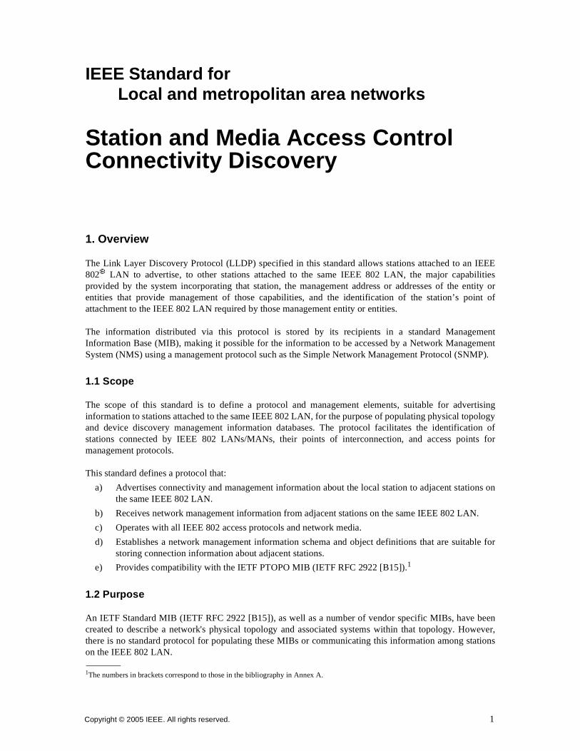
The Link Layer Discovery Protocol (LLDP) specified in this standard allows stations attached to an IEEE802® LAN to advertise, to other stations attached to the same IEEE 802 LAN, the major capabilitiesprovided by the system incorporating that station, the management address or addresses of the entity orentities that provide management of those capabilities, and the identification of the station’s point ofattachment to the IEEE 802 LAN required by those management entity or entities.
The information distributed via this protocol is stored by its recipients in a standard ManagementInformation Base (MIB), making it possible for the information to be accessed by a Network ManagementSystem (NMS) using a management protocol such as the Simple Network Management Protocol (SNMP).
1.1 Scope
The scope of this standard is to define a protocol and management elements, suitable for advertisinginformation to stations attached to the same IEEE 802 LAN, for the purpose of populating physical topologyand device discovery management information databases. The protocol facilitates the identification ofstations connected by IEEE 802 LANs/MANs, their points of interconnection, and access points formanagement protocols.
This standard defines a protocol that:
a) Advertises connectivity and management information about the local station to adjacent stations onthe same IEEE 802 LAN.
b) Receives network management information from adjacent stations on the same IEEE 802 LAN.
c) Operates with all IEEE 802 access protocols and network media.
d) Establishes a network management information schema and object definitions that are suitable forstoring connection information about adjacent stations.
e) Provides compatibility with the IETF PTOPO MIB (IETF RFC 2922 [B15]).1
1.2 Purpose
An IETF Standard MIB (IETF RFC 2922 [B15]), as well as a number of vendor specific MIBs, have beencreated to describe a network's physical topology and associated systems within that topology. However,there is no standard protocol for populating these MIBs or communicating this information among stationson the IEEE 802 LAN.
1The numbers in brackets correspond to those in the bibliography in Annex A.
Copyright © 2005 IEEE. All rights reserved. 1
IEEEStd 802.1AB-2005 LOCAL AND METROPOLITAN AREA NETWORKS
This standard specifies the necessary protocol and management elements to:
a) Facilitate multi-vendor inter-operability and the use of standard management tools to discover andmake available physical topology information for network management.
b) Make it possible for network management to discover certain configuration inconsistencies ormalfunctions that can result in impaired communication at higher layers.
c) Provide information to assist network management in making resource changes and/or re-configurations that correct configuration inconsistencies or malfunctions identified in b) above.
NOTE—The LLDP protocol is designed to advertise information useful for discovering pertinent information about aremote port and to populate topology MIBs. It is not intended to act as a configuration protocol for remote systems, noras a mechanism to signal control information between ports. During the operation of LLDP, it may be possible todiscover configuration inconsistencies between systems on the same IEEE 802 LAN. LLDP does not provide amechanism to resolve those inconsistencies. Rather, it provides a means to report discovered information to higher layermanagement entities. A port in this context is a single point of attachment to the LAN infrastructure.2
2Notes in text, tables, and figures are given for information only and do not contain requirements needed to implement the standard.
2 Copyright © 2005 IEEE. All rights reserved.

IEEESTATION AND MEDIA ACCESS CONTROL CONNECTIVITY DISCOVERY Std 802.1AB-2005
2. References
The following standards contain provisions which, through reference in this text, constitute provisions ofthis standard. At the time of this publication, editions indicated were valid. All standards are subject torevision, and parties to agreements based on this standard are encouraged to investigate the possibility ofapplying the most recent editions of the standards indicated below. Members of ISO and IEC maintainregisters of currently valid International standards.
Abstract Syntax Notation One (ASN.1): Specification of Basic Notation, ITU-T Rec. X.680 (2002) ISO/IEC8824-1:2002.3
IEEE Std 802®-2001, IEEE Standard for Local and Metropolitan Area Networks: Overview andArchitecture.4, 5
IEEE Std 802a™-2003, IEEE Standard for Local and Metropolitan Area Networks: Overview andArchitecture—Amendment 1: Ethertypes for Prototype and Vendor-Specific Protocol Development.
IEEE Std 802.1D™-2004, Standard for Local and Metropolitan Area Networks: Media Access Control(MAC) Bridges.
IEEE Std 802.1Q™-1998, IEEE Standards for Local and Metropolitan Area Networks: Virtual BridgedLocal Area Networks.
IEEE Std 802.1X™-2004, IEEE Standard for Local and Metropolitan Area Networks—Port-Based NetworkAccess Control.
IEEE Std 802.3™-2002, Part 3: Carrier Sense Multiple Access with Collision Detection (CSMA/CD) AccessMethod and Physical Layer Specifications.
IEEE Std 802.3ae™-2002, Part 3: Carrier Sense Multiple Access with Collision Detection (CSMA/CD)Access Method and Physical Layer Specifications—Amendment: Media Access Control (MAC)Parameters, Physical Layers, and Management Parameters for 10 Gb/s Operation.
IEEE Std 802.3af™-2003, Part 3: Carrier Sense Multiple Access with Collision Detection (CSMA/CD)Access Method and Physical Layer Specifications—Amendment: Data Terminal Equipment (DTE) Powervia Media Dependent Interface (MDI).
IETF RFC 1493, Definitions of Managed Objects for Bridges, Decker, E., Langille, P., Rijsinghani, A., and
McCloghrie, K., July 1993.6
IETF RFC 1812, Requirements for IP Version 4 Routers, Baker, F., June 1995.
IETF RFC 2108, Definitions of Managed Objects for IEEE 802.3 Repeater Devices using SMIv2, de Graaf,K., and Romascanu, D., February 1997.
3ASN.1 standards are available on-line by Web browser at http://asn1.elibel.tm.fr/en/standards/index.htm#asn1.4IEEE and 802 are registered trademarks in the U.S. Patent & Trademark Office, owned by the Institute of Electrical and ElectronicsEngineers, Incorporated.5IEEE publications are available from the Institute of Electrical and Electronics Engineers, 445 Hoes Lane, Piscataway, NJ 08855,USA (http://standards.ieee.org).6Internet RFCs are retrievable by FTP at ds.internic.net/rfc/rfcnnnn.txt, or by Web browser at http://www.ietf.org/rfc/rfcNNNN.txt(where NNNN is the RFC number prefixed with zeroes as necessary to make a four digit number), or call InterNIC at 1-800-444-4345for information about receiving copies through the mail.
Copyright © 2005 IEEE. All rights reserved. 3

IEEEStd 802.1AB-2005 LOCAL AND METROPOLITAN AREA NETWORKS
IETF RFC 2011, SNMPv2 Management Information Base for the Internet Protocol using SMIv2,McCloghrie, K., November 1996.
IETF RFC 2021, Remote Network Monitoring Management Information Base Version 2 using SMIv2, Waldbusser, S., January 1997.
IETF RFC 2669, DOCSIS Cable Device MIB Cable Device Management Information Base for DOCSIScompliant Cable Modems and Cable Modem Termination Systems, St. Johns, M., August 1999.
IETF RFC 2670, Radio Frequency (RF) Interface Management Information Base for MCNS/DOCSIScompliant RF interfaces, St. Johns, M., August 1999.
IETF RFC 2674, Definitions of Managed Objects for Bridges with Traffic Classes, Multicast Filtering andVirtual LAN Extensions, Bell, E., Smith, A., Langille, P., Rijhsinghani, A., and McCloghrie, K., August1999.
IETF RFC 2683, IMAP4 Implementation Recommendations, Leiba, B., September 1999.
IETF RFC 2737, Entity MIB (Version 2), McCloghrie, K., and Bierman, A., December 1999.
IETF RFC 2863, The Interfaces Group MIB, McCloghrie, K. and Kastenholz, F., June 2000.
IETF RFC 3046, DHCP Relay Agent Information Option, Patrick, M., January 2001.
IETF RFC 3232, Assigned Numbers: RFC 1700 is Replaced by an On-line Database, Reynolds, J., January2002.7
IETF RFC 3410, Introduction and Applicability Statements for Internet-Standard Management Framework,Case, J., Mundy, R.,Partain, D., and Stewart, B., December 2002.
IETF RFC 3418, Management Information Base (MIB) for the Simple Network Management Protocol (SNMP), Presuhn, R., ED., December 2002.
IETF RFC 3621, Power Ethernet MIB, Berger, A. and Romascanu, D., December 2003.
IETF RFC 3629, UTF-8, a transformation format of ISO 10646, Yergeau, F. November 2003.
IETF RFC 3636, Definitions of Managed Objects for IEEE 802.3 Medium Attachment Units (MAUs),Flick, J., September 2003.
7The IETF RFC 3232 ianaAddressFamilyNumbers on-line database module is accessible through a web page (currently, http://www.iana.org).
4 Copyright © 2005 IEEE. All rights reserved.
IEEESTATION AND MEDIA ACCESS CONTROL CONNECTIVITY DISCOVERY Std 802.1AB-2005
3. Definitions and numerical representation
3.1 Definitions
For purposes of this standard, the following terms and definitions apply. IEEE 100, The AuthoritativeDictionary of IEEE Standard Terms, Seventh Edition [B2], as well as other referenced IEEE standards andIETF RFCs, should be referenced for terms not defined in this clause.
3.1.1 alpha-numeric information: Information that is encoded using the UTF-8 octet sequence [IETF RFC3629].
3.1.2 chassis: A physical component incorporating one or more IEEE 802 LAN stations and their associatedapplication functionality.
3.1.3 chassis identifier: An administratively assigned name that identifies the particular chassis within thecontext of an administrative domain that comprises one or more networks.
3.1.4 IEEE 802® LAN: Local area network (LAN) technologies that provide a media access control (MAC)Service equivalent to the MAC Service defined in ISO/IEC 15802-1. IEEE 802 LANs include IEEE Std802.3, (CSMA/CD), IEEE Std 802.5™ (Token Ring), IEEE Std 802.11™ (Wireless), and ISO 9314-2(FDDI) LANs.
3.1.5 IEEE 802® LAN station: An IEEE 802-compatible entity that incorporates all the necessarymechanisms to participate in media access control of an IEEE 802 LAN, and that is at least capable ofproviding the MAC service plus the mandatory capabilities of the LLC.
3.1.6 Link Layer Discovery Protocol (LLDP): A media-independent protocol intended to be run on allIEEE 802® LAN stations and to allow an LLDP agent to learn the connectivity and managementinformation from adjacent stations.
3.1.7 LLDP agent: The protocol entity that implements LLDP for a particular IEEE 802® chassis.
3.1.8 MAC service access point (MSAP): The access point for MAC services provided to the LLCsublayer.
3.1.9 MSAP identifier: The identifier of a MAC service access point.
NOTE—In this standard, the concatenation of the chassis ID and the port ID is used by LLDP as an MSAP identifier, toidentify the LLDP agent and physical port associated with an IEEE 802® LAN station.
3.1.10 management entity: The protocol entity that implements a particular network management protocoland that provides access support to a MIB associated with the protocol and implemented on a host chassis.
3.1.11 Management Information Base (MIB): The instantiation of MIB module.
3.1.12 Management Information Base module (MIB module): The specification or schema for a database that can be populated with the information required to support a network management informationsystem.
3.1.13 network: An interconnected group of systems, each comprising one or more IEEE 802® LANstations.
3.1.14 Network Management System (NMS): A management system that is capable of utilizing theinformation in a MIB.
Copyright © 2005 IEEE. All rights reserved. 5
IEEEStd 802.1AB-2005 LOCAL AND METROPOLITAN AREA NETWORKS
3.1.15 object identifier (OID): An identifier used to identify the type of a MIB object. Each MIB object’sobject type is named by an object identifier, an administratively assigned name.
3.1.16 physical network topology: The identification of systems, of IEEE 802® LAN stations that composeeach system, and of the IEEE 802 LAN stations that attach to the same IEEE 802® LAN.
3.1.17 port: The entity in a chassis/system to support an MSAP. A port incorporates one and only oneMSAP and identifies the collection of manageable entities that provide the MAC Service at the MSAP.
3.1.18 port identifier: An administratively assigned name that identifies the particular port within thecontext of a system, where the identification is convenient, local to the system, and persistent for thesystem’s use and management (whereas the MAC address that globally identifies the MSAP can not be).
3.1.19 system: A managed collection of hardware and software components incorporating one or morechassises, stations and ports.
3.1.20 station only: A non-forwarding IEEE 802® LAN station such as a user workstation, network fileserver, or print server.
3.1.21 type, length, value (TLV): A short, variable length encoding of an information element consisting ofsequential type, length, and value fields where the type field identifies the type of information, the lengthfield indicates the length of the information field in octets, and the value field contains the information,itself.
3.2 Numerical representation
Decimal, hexadecimal, and binary numbers are used within this document. For clarity, decimal numbers aregenerally used to represent counts, hexadecimal numbers are used to represent addresses, and binarynumbers are used to describe bit patterns within binary fields.
Decimal numbers are represented in their usual 0, 1, 2, … format. Hexadecimal numbers are represented bya string of one or more hexadecimal (0-9, A-F) digits followed by the subscript 16, except in C-codecontexts, where they are written as 0x123EF2 etc. Binary numbers are represented by a string of one ormore binary (0,1) digits, followed by the subscript 2. Thus the decimal number “26” may also be representedas “1A16” or “110102”.
MAC addresses and OUI/EUI values are represented as strings of 8-bit hexadecimal numbers separated byhyphens and without a subscript, as for example “01-80-C2-00-00-15” or “AA-55-11”.
6 Copyright © 2005 IEEE. All rights reserved.
IEEESTATION AND MEDIA ACCESS CONTROL CONNECTIVITY DISCOVERY Std 802.1AB-2005
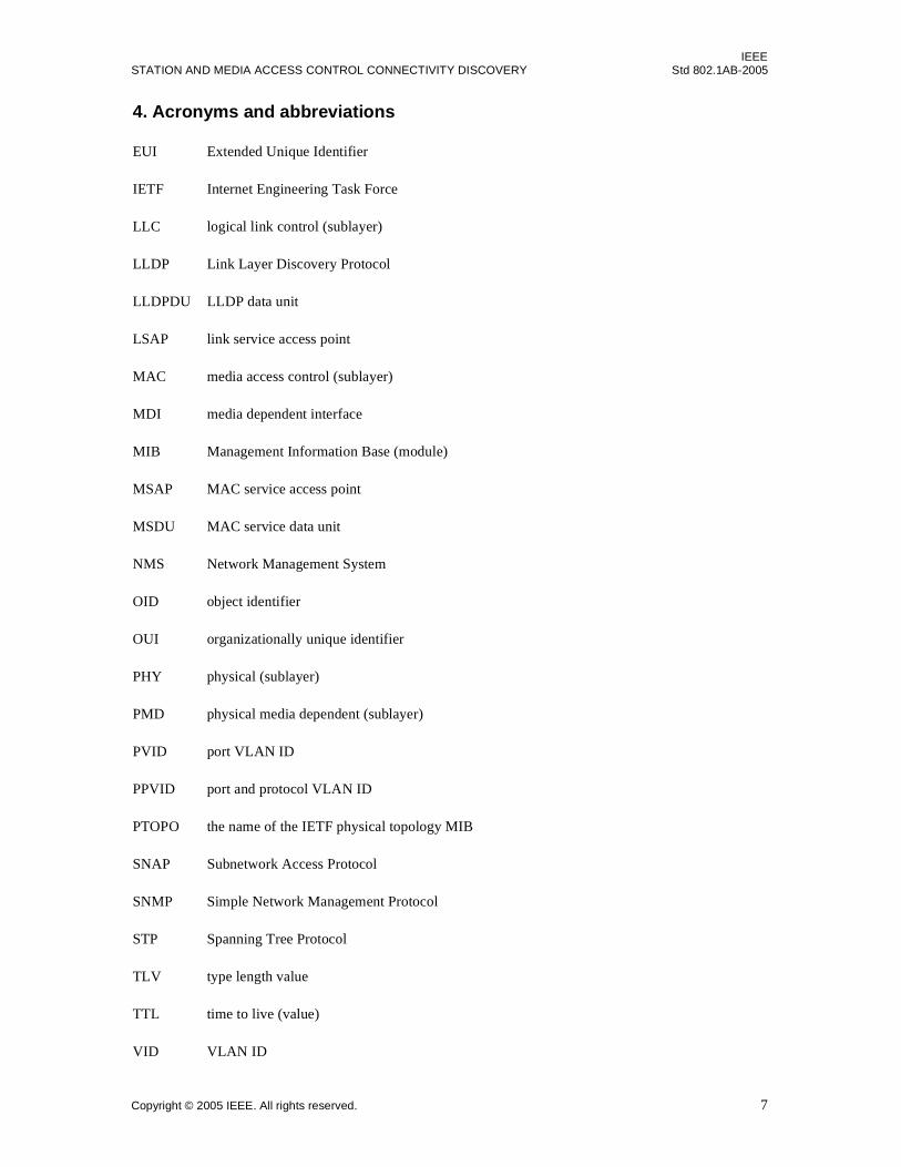
4. Acronyms and abbreviations
EUI Extended Unique Identifier
IETF Internet Engineering Task Force
LLC logical link control (sublayer)
LLDP Link Layer Discovery Protocol
LLDPDU LLDP data unit
LSAP link service access point
MAC media access control (sublayer)
MDI media dependent interface
MIB Management Information Base (module)
MSAP MAC service access point
MSDU MAC service data unit
NMS Network Management System
OID object identifier
OUI organizationally unique identifier
PHY physical (sublayer)
PMD physical media dependent (sublayer)
PVID port VLAN ID
PPVID port and protocol VLAN ID
PTOPO the name of the IETF physical topology MIB
SNAP Subnetwork Access Protocol
SNMP Simple Network Management Protocol
STP Spanning Tree Protocol
TLV type length value
TTL time to live (value)
VID VLAN ID
Copyright © 2005 IEEE. All rights reserved. 7

IEEEStd 802.1AB-2005 LOCAL AND METROPOLITAN AREA NETWORKS
5. Conformance
5.1 Terminology
For consistency with IEEE and existing IEEE 802.1™ standards, requirements placed upon conformantimplementations of this standard are expressed using the following terminology:
a) shall is used for mandatory requirements;
b) may is used to describe implementation or administrative choices (“may” means “is permitted to,”and hence, “may” and “may not” mean precisely the same thing);
c) should is used for recommended choices (the behaviors described by “should” and “should not” areboth permissible but not equally desirable choices).
The PICS proforma provided in Annex B reflects the occurrences of the words shall, may, and should withinthe standard.
The standard avoids needless repetition and apparent duplication of its formal requirements by using is, isnot, are, and are not for definitions and the logical consequences of conformant behavior. Behavior that ispermitted but is neither always required nor directly controlled by an implementor or administrator, orwhose conformance requirement is detailed elsewhere, is described by can. Behavior that never occurs in aconformant implementation or system of conformant implementations is described by cannot. The wordallow is used as a replacement for the cliche “Support the ability for”, and the word capability means “canbe configured to.”
5.2 Required capabilities
A system for which conformance to this standard is claimed shall, for all ports for which support is claimed,include the following capabilities:
a) If port access is controlled by IEEE Std 802.1X-20048, LLDP exchanges shall be through thecontrolled port as specified in Clause 6.
b) The destination and source addressing shall conform to 8.1 and 8.2.
c) Ethertype encapsulation shall conform to 8.3.
d) LLDPDU recognition and reception shall conform to 8.4 and 10.3.1.
e) LLDPDU encapsulation shall conform to the specifications in 9.2.
f) The basic TLV format capability shall be implemented as defined in 9.4.
g) The basic management set of TLVs shall be implemented as defined in 9.5.
h) The Organizationally Specific TLV format capability shall be implemented as defined in 9.6.
i) The protocol shall conform to the specifications for all Clause 10 subclauses indicated in Table 10-1for the particular operating mode (transmit only, receive only, or transmit and receive) beingimplemented.
j) If receipt of LLDPDUs is supported, for every set of TLVs (the basic management set and anyorganizationally specific sets) supported, support shall be implemented for receipt of every TLVdefined in the set.
k) If transmission of LLDPDUs is supported, for every set of TLVs (the basic management set and anyorganizationally specific sets) supported, support shall be implemented for transmission of everyTLV defined in the set.
8Information on references can be found in Clause 2.
8 Copyright © 2005 IEEE. All rights reserved.
IEEESTATION AND MEDIA ACCESS CONTROL CONNECTIVITY DISCOVERY Std 802.1AB-2005
l) If transmission of LLDPDUs is supported, for every set of TLVs (the basic management set and anyorganizationally specific sets) supported, a capability shall be implemented for users to determinewhich optional TLVs are transmitted in any particular LLDPDU.
m) If SNMP is supported, the system shall conform to the LLDP management specifications in Clause 11.and shall implement the sections of the basic LLDP MIB indicated in Table 12-1 for the operatingmode being implemented.
n) If SNMP is not supported, the system shall provide storage and retrieval capability equivalent to thefunctionality specified in 11.1 for the operating mode being implemented.
5.3 Optional capabilities
A system for which conformance to this standard is claimed, for each port for which support is claimed,may:
a) Implement the entire IEEE 802.1 Organizationally Specific TLV extension set and the associatedIEEE 802.1 MIB extension capability defined in Annex F.
b) Implement the entire IEEE 802.3 Organizationally Specific TLV extension set and the associatedIEEE 802.3 MIB extension capability defined in Annex G.
Copyright © 2005 IEEE. All rights reserved. 9
IEEEStd 802.1AB-2005 LOCAL AND METROPOLITAN AREA NETWORKS
6. Architectural overview
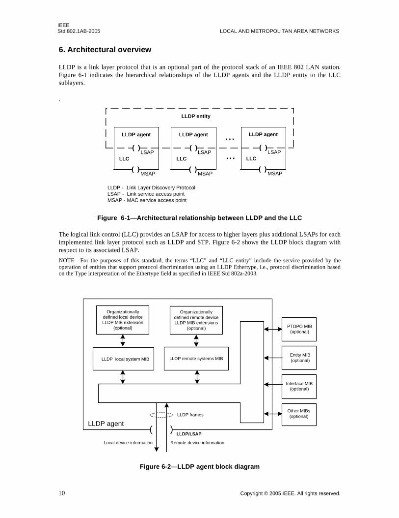
LLDP is a link layer protocol that is an optional part of the protocol stack of an IEEE 802 LAN station.Figure 6-1 indicates the hierarchical relationships of the LLDP agents and the LLDP entity to the LLCsublayers.
.
Figure 6-1—Architectural relationship between LLDP and the LLC
The logical link control (LLC) provides an LSAP for access to higher layers plus additional LSAPs for eachimplemented link layer protocol such as LLDP and STP. Figure 6-2 shows the LLDP block diagram withrespect to its associated LSAP.
NOTE—For the purposes of this standard, the terms “LLC” and “LLC entity” include the service provided by theoperation of entities that support protocol discrimination using an LLDP Ethertype, i.e., protocol discrimination basedon the Type interpretation of the Ethertype field as specified in IEEE Std 802a-2003.
Figure 6-2—LLDP agent block diagram
LLDP - Link Layer Discovery ProtocolLSAP - Link service access pointMSAP - MAC service access point
( )
LLDP agent
LLCLSAP
( )MSAP
( )
LLDP agent
LLCLSAP
( )MSAP
( )
LLDP agent
LLCLSAP
( )MSAP
LLDP entity
...
...
LLDP local system MIB LLDP remote systems MIB
LLDP agentLLDP frames
( )
LLDP manager
LLDP/LSAP
Local device information Remote device information
Organizationallydefined local deviceLLDP MIB extension
(optional)
Organizationallydefined remote deviceLLDP MIB extensions
(optional)
Entity MIB(optional)
Interface MIB(optional)
PTOPO MIB(optional)
Other MIBs(optional)
10 Copyright © 2005 IEEE. All rights reserved.

IEEESTATION AND MEDIA ACCESS CONTROL CONNECTIVITY DISCOVERY Std 802.1AB-2005
If port access is controlled by IEEE Std 802.1X-2004, Clause 8, LLDP exchanges shall run on the controlledport. (See also IEEE Std 802.1D-2004, 7.12.7). In a bridge, LLDP operates as an LLC procedure over thebridge port and is therefore not affected by the spanning tree port state.
Copyright © 2005 IEEE. All rights reserved. 11
IEEEStd 802.1AB-2005 LOCAL AND METROPOLITAN AREA NETWORKS
7. Principles of operation
LLDP uses the services of the LLC and the MAC to transmit and receive information to and from otherLLDP agents, as defined in 8.1, 8.2, 8.3, and 8.4.
7.1 LLDP operational modes
LLDP is a one way protocol. An LLDP agent can transmit information about the capabilities and currentstatus of the system associated with its MSAP identifier. The LLDP agent can also receive informationabout the capabilities and current status of the system associated with a remote MSAP identifier. However,LLDP agents are not provided any means of soliciting information from other LLDP agents via thisprotocol.
LLDP allows the transmitter and the receiver to be separately enabled, making it possible to configure animplementation to restrict the local LLDP agent either to transmit only or receive only, or to allow the localLLDP agent to both transmit and receive LLDP information.
7.2 Connectivity and management information
The information fields in each LLDP frame are contained in a Link Layer Discovery Protocol Data Unit(LLDPDU) as a sequence of short, variable length, information elements known as TLVs that each includetype, length, and value fields where:
a) Type identifies what kind of information is being sent.
b) Length indicates the length of the information string in octets.
c) Value is the actual information that needs to be sent (for example, a binary bit map or an alpha-numeric string that can contain one or more fields).
Each LLDPDU includes four mandatory TLVs plus optional TLVs as selected by network management:
a) A Chassis ID TLV.
b) A Port ID TLV.
c) A Time To Live TLV.
d) From zero to n optional TLVs, as allowed by the space limitation of the LLDPDU.
e) An End Of LLDPDU TLV.
The chassis ID and the port ID values are concatenated to form a logical MSAP identifier that is used by therecipient to identify the sending LLDP agent/port. Both the chassis ID and port ID values can be defined in anumber of convenient forms. Once selected however, the chassis ID/port ID value combination remains thesame as long as the particular port remains operable.
A non-zero value in the TTL field of Time To Live TLV tells the receiving LLDP agent how long allinformation pertaining to this LLDPDU’s MSAP identifier will be valid so that all the associatedinformation can later be automatically discarded by the receiving LLDP agent if the sender fails to update itin a timely manner.
The End Of LLDPDU TLV marks the end of the LLDPDU.
The format for the LLDPDU is defined in 9.2. The TLV categories and the basic TLV format are defined in9.3 and 9.4. The specific format and field contents for the Chassis ID TLV are defined in 9.5.2; for thePort ID TLV, in 9.5.3; for the Time To Live TLV in 9.5.4; and for the End Of LLDPDU TLV, in 9.5.1.
12 Copyright © 2005 IEEE. All rights reserved.
IEEESTATION AND MEDIA ACCESS CONTROL CONNECTIVITY DISCOVERY Std 802.1AB-2005
NOTE—A time to live (TTL) value of zero, tells the recipient LLDP agent that all the system information associatedwith the LLDPDU’s MSAP identifier is to be deleted. This can be used, for example, to signal that the sending port hasinitiated a port shutdown procedure.
7.3 Optional information categories
Three sets of optional use TLVs are currently defined and may be used to describe the system and/or toassist in the detection of configuration inconsistencies associated the MSAP identifier:
a) Basic management TLV set (this set is required in all LLDP implementations):
1) Port Description TLV.
2) System Name TLV.
3) System Description TLV.
4) System Capabilities TLV (indicates both the system’s capabilities and its current primarynetwork function, such as end station, bridge, router).
5) Management Address TLV.
b) IEEE 802.1 Organizationally Specific TLV set (this set is optional for all LLDP implementations).
1) Port VLAN ID TLV.
2) Port And Protocol VLAN ID TLV.
3) VLAN Name TLV.
4) Protocol Identity TLV.
c) IEEE 802.3 Organizationally Specific TLV set (this set is optional for all LLDP implementations).
1) MAC/PHY Configuration/Status TLV (indicates the auto-negotiation capability and theduplex/speed status of IEEE 802.3 MAC/PHYs).
2) Power Via MDI TLV (indicates the capabilities and current status of IEEE 802.3 PMDs thateither require or are able to provide power over twisted-pair copper links).
3) Link Aggregation TLV (indicates the current link aggregation status of IEEE 802.3 MACs).
4) Maximum Frame Size TLV (indicates the maximum supported IEEE 802.3 frame size).
Table 9-1 includes a list of the currently defined optional TLVs in the basic management set and providessubclause references for their specific definitions.
Organizationally Specific TLVs can be defined by either the professional organizations or the individualvendors that are involved with the particular functionality being implemented within a system. The basicformat and procedures for defining Organizationally Specific TLVs are provided in 9.6.
Annex F contains definitions of Organizationally Specific TLVs associated with IEEE Std 802.1. Annex Gcontains definitions of Organizationally Specific TLVs associated with IEEE Std 802.3. Annex E containsan informative discussion of how several Organizationally Specific TLVs could be used to detect potentialproblems in communications networks.
7.4 LLDP design principles
LLDP is designed to operate in a manner consistent with the principles of the Internet-standard ManagementFramework, which describes the separation of a data modeling language (for example, SMIv2) fromcontent-specific data models (for example, the LLDP remote systems MIB), and from messages andprotocol operations used to manipulate the data (for example, SNMPv3). Managed objects are accessed viaa virtual information store (the MIB). MIB objects are generally accessed through SNMP. Objects in theMIB are defined using the mechanisms of the Structure of Management Information (SMI). For an overviewof this structure, see section 7 of IETF RFC 3410.
Copyright © 2005 IEEE. All rights reserved. 13
IEEEStd 802.1AB-2005 LOCAL AND METROPOLITAN AREA NETWORKS
Clause 12, Annex G, and Annex F include specifications for an LLDP MIB module and for IEEE 802.1 andIEEE 802.3 extension MIB modules that are compliant with the SMIv2 as defined in IETF STD 58, RFC2578 [B10]; IETF STD 58, RFC 2579 [B11]; and IETF STD 58, RFC 2580 [B12].
7.5 TLV selection
Information for constructing the various TLVs to be sent is stored in the LLDP local system MIB. Theselection of which particular TLVs to send is under control of the network manager. Information receivedfrom remote LLDP agents is stored in the LLDP remote systems MIB.
7.6 Transmission principles
Transmission can be initiated either by the expiration of a transmit countdown timing counter or by a changein the status or value in one or more of the information elements (managed objects) associated with the localsystem. When a transmit cycle is initiated, the LLDP manager extracts the managed objects from the LLDPlocal system MIB and formats this information into TLVs. The TLVs are inserted into the LLDPDU that ispassed to the LLDP transmit module. The LLDP transmit module prepends addressing parameters to theLLDPDU as defined in 9.2, 9.3, and 9.4. The LLDPDU and TLV formats are defined in Clause 9 The LLDPtransmit state machine is described in 10.4 and 10.5.4.
NOTES
1—Because a transmission cycle can be initiated whenever a change occurs within the LLDP local system MIB, it ispossible that a series of successive changes over a short period of time could trigger a number of LLDP frames to besent, each reporting only a single change, LLDP utilizes a transmission delay timer that can be set by networkmanagement to ensure that there is a defined minimum time between successive LLDP frame transmissions.
2—Under normal circumstances, the information in the receiving LLDP agent’s remote systems MIB is refreshedperiodically to avoid being discarded due to aging. To prevent the receiving LLDP agent’s remote systems MIBinformation being aged out because a refresh frame has been lost in transmission, the sending LLDP agent will typicallyset the TTL value so that several refresh cycles will occur before the received MIB information will age out.
7.7 Reception principles
The LLDP receive module uses the services of the LLC entity to recognize that the incomingMA_UNITDATA.indication contains the correct combination of destination address and MSDU headervalues to identify it as being derived from an incoming LLDP frame. The LLDPDU recognition is defined in8.4 and 10.3.1.
7.7.1 LLDPDU and TLV error handling
The LLDPDU is checked to ensure that it contains the correct sequence of mandatory TLVs and then eachoptional TLV is validated in succession. LLDPDUs and TLVs that contain detectable errors are discarded.TLVs that are not recognized, but that also contain no basic format errors, are assumed to be validated andare stored for possible later retrieval by network management (see 10.3.2 and 10.3.5).
7.7.2 LLDP remote systems MIB update
The LLDP remote systems MIB is updated after all TLVs have been validated. LLDP remote system MIBupdate procedures are defined in 10.3.3, 10.3.4, 10.3.5, 10.3.6, and 10.3.7. The LLDP receive state machineis described in 10.4 and 10.5.5.
14 Copyright © 2005 IEEE. All rights reserved.
IEEESTATION AND MEDIA ACCESS CONTROL CONNECTIVITY DISCOVERY Std 802.1AB-2005
7.8 Relationship between LLDP and IETF MIBs
LLDP is designed to operate in conjunction with MIBs defined by IETF, IEEE 802, and others. Thefollowing subclauses discuss the relationship between LLDP and IETF MIBs. LLDP agents automaticallynotify the managers of these MIBs whenever there is a value or status change in an LLDP MIB object.
LLDP managed objects for the local system are stored in the LLDP local system MIB. Information receivedfrom a remote LLDP agent is stored in the local LLDP agent’s LLDP remote system MIB. NOTE—In this standard, managed objects for an LLDP MIB module are defined as they would be for an SNMP MIB.However, it is not required for LLDP implementations to support SNMP to store and retrieve system data. LLDP agentsneed to have a place to store both information about the local system and information they have received about remotesystems. No particular implementation is implied.
7.8.1 IETF Physical Topology MIB
The Physical Topology MIB (IETF RFC 2922 [B15]) allows a LLDP agent to expose learned physicaltopology information, using a standard MIB. LLDP is intended to support the PTOPO MIB.
NOTE—The LLDP MIB module is a logical superset of the IETF Physical Topology MIB, and from a functional pointof view if the LLDP MIB module is implemented, there is no need to implement the PTOPO MIB defined in RFC 2922[B15].
7.8.2 IETF Entity MIB
The Entity MIB (IETF RFC 2737) allows the physical component inventory and hierarchy to be identified.Chassis IDs passed in the LLDPDU may identify entPhysicalTable entries. SNMP agents that implement theLLDP MIB should implement the entPhysicalAlias object from the Entity MIB version 2 or higher.
7.8.3 IETF Interfaces MIB
The Interfaces MIB (IETF RFC 2863) provides a standard mechanism for managing network ports. Port IDspassed in the LLDPDU may identify ifTable (or entPhysicalTable) entries. SNMP agents that implement theLLDP MIB, should also implement the ifTable and ifXTable for the ports that are represented in theInterfaces MIB.
Copyright © 2005 IEEE. All rights reserved. 15
IEEEStd 802.1AB-2005 LOCAL AND METROPOLITAN AREA NETWORKS
8. LLDPDU transmission, reception, and addressing
This standard is intended to be compatible with all IEEE 802 MACs.
LLDP uses the service provided by the LLDP/LSAP and LLC to transmit and receive LLDPDUs. Each
LLDPDU is transmitted as a single MAC service request by an LLC entity that uses a single instance of the
MAC Service provided at an MSAP. Each incoming LLDP frame is received at the MSAP by the LLC
entity as a MAC service indication.
NOTE—For the purposes of this standard, the terms “LLC” and “LLC entity” include the service provided by theoperation of entities that support protocol discrimination using an Ethertype, i.e., protocol discrimination based on theEthertype field specified in IEEE Std 802a-2003.
The parameters of each service request and service indication comprise:
a) destination address.
b) source address.
c) Ethertype.
d) LLDPDU.
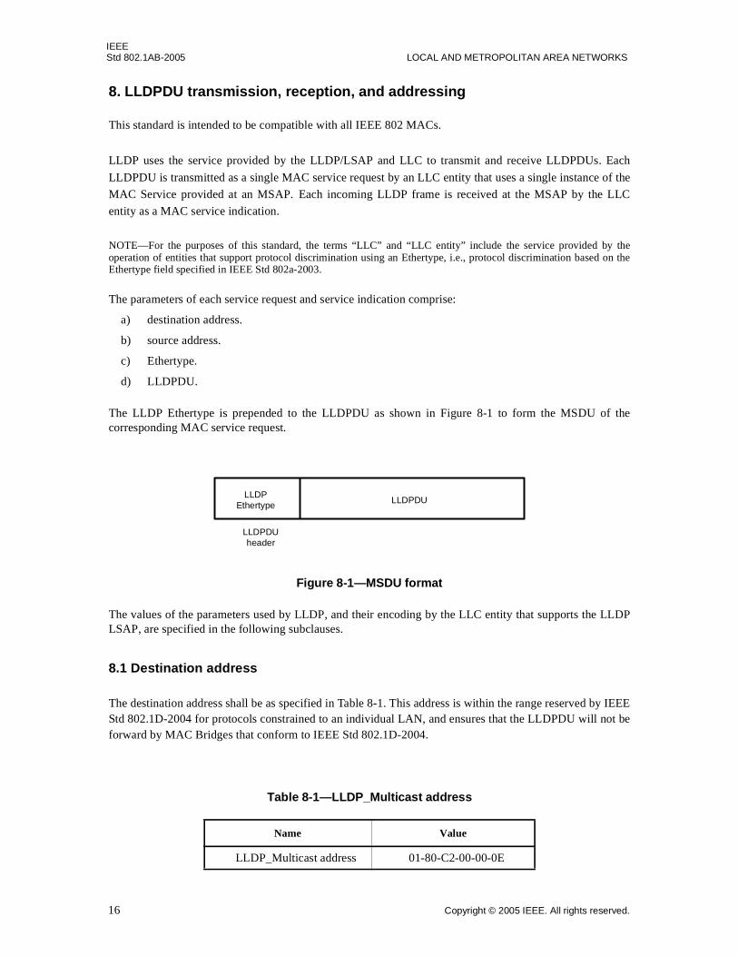
The LLDP Ethertype is prepended to the LLDPDU as shown in Figure 8-1 to form the MSDU of thecorresponding MAC service request.
Figure 8-1—MSDU format
The values of the parameters used by LLDP, and their encoding by the LLC entity that supports the LLDPLSAP, are specified in the following subclauses.
8.1 Destination address
The destination address shall be as specified in Table 8-1. This address is within the range reserved by IEEEStd 802.1D-2004 for protocols constrained to an individual LAN, and ensures that the LLDPDU will not beforward by MAC Bridges that conform to IEEE Std 802.1D-2004.
Table 8-1—LLDP_Multicast address
Name Value
LLDP_Multicast address 01-80-C2-00-00-0E
LLDPEthertype LLDPDU
LLDPDUheader
16 Copyright © 2005 IEEE. All rights reserved.
IEEESTATION AND MEDIA ACCESS CONTROL CONNECTIVITY DISCOVERY Std 802.1AB-2005
NOTE—This address has been selected from amongst those addresses that are not forwarded by MAC Bridges, or byVLAN-aware Bridges (see IEEE Std 802.1Q-1998).
8.2 Source address
The source address shall be the MAC address of the sending station or port.
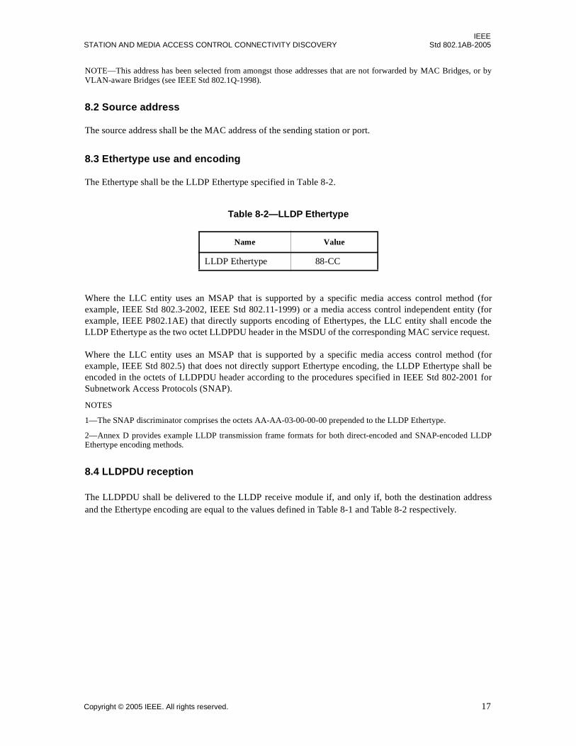
8.3 Ethertype use and encoding
The Ethertype shall be the LLDP Ethertype specified in Table 8-2.
Where the LLC entity uses an MSAP that is supported by a specific media access control method (forexample, IEEE Std 802.3-2002, IEEE Std 802.11-1999) or a media access control independent entity (forexample, IEEE P802.1AE) that directly supports encoding of Ethertypes, the LLC entity shall encode theLLDP Ethertype as the two octet LLDPDU header in the MSDU of the corresponding MAC service request.
Where the LLC entity uses an MSAP that is supported by a specific media access control method (forexample, IEEE Std 802.5) that does not directly support Ethertype encoding, the LLDP Ethertype shall beencoded in the octets of LLDPDU header according to the procedures specified in IEEE Std 802-2001 forSubnetwork Access Protocols (SNAP).
NOTES
1—The SNAP discriminator comprises the octets AA-AA-03-00-00-00 prepended to the LLDP Ethertype.
2—Annex D provides example LLDP transmission frame formats for both direct-encoded and SNAP-encoded LLDPEthertype encoding methods.
8.4 LLDPDU reception
The LLDPDU shall be delivered to the LLDP receive module if, and only if, both the destination addressand the Ethertype encoding are equal to the values defined in Table 8-1 and Table 8-2 respectively.
Table 8-2—LLDP Ethertype
Name Value
LLDP Ethertype 88-CC
Copyright © 2005 IEEE. All rights reserved. 17

IEEEStd 802.1AB-2005 LOCAL AND METROPOLITAN AREA NETWORKS
9. LLDPDU and TLV formats
9.1 LLDPDU bit and octet ordering conventions
All LLDPDUs shall contain an integral number of octets. The octets in an LLDPDU are numbered startingfrom 1 and increasing in the order they are put into the LLDP frame. The bits are numbered from 0 to 7,where 0 is the low-order bit.
When consecutive bits within an octet are used to represent a binary number, the highest bit number has themost significant value. When consecutive octets are used to represent a binary number, the lower octetnumber has the most significant value. All TLVs respect these bit and octet ordering conventions, thusallowing communications to take place.
9.2 LLDPDU format
The LLDPDU shall contain an ordered sequence of three mandatory TLVs followed by one or more optionalTLVs plus an End Of LLDPDU TLV, as shown in Figure 9-1:
a) Three mandatory TLVs shall be included at the beginning of each LLDPDU and shall be in the ordershown:
1) Chassis ID TLV.
2) Port ID TLV.
3) Time To Live TLV.
b) Optional TLVs as selected by network management (may be inserted in any order).
c) The End Of LLDPDU TLV shall be the last TLV in the LLDPDU.
Figure 9-1—LLDPDU Format
The maximum length of the LLDPDU shall be the maximum information field length allowed by theparticular transmission rate and protocol. In IEEE 802.3 MACs, for example, the maximum LLDPDUlength is the maximum data field length for the basic, untagged MAC frame (1500 octets).
9.3 TLV categories
The TLVs are grouped into two general categories:
a) A set of TLVs that are considered to be basic to the management of network stations and that are arequired capability of all LLDP implementations. Each TLV in this category is identified by anunique TLV type value that indicates the particular kind of information contained in the TLV.
b) Organizationally specific extension sets of TLVs that are defined by standards groups such as IEEE802.1 and IEEE 802.3 and others to enhance management of network stations that are operating withparticular media and/or protocols.
M - mandatory TLV - required for all LLDPDUs
Time ToLive TLV
Chassis IDTLV
OptionalTLV
Port IDTLV
OptionalTLV
... End OfLLDPDU TLV
M M M M
18 Copyright © 2005 IEEE. All rights reserved.

IEEESTATION AND MEDIA ACCESS CONTROL CONNECTIVITY DISCOVERY Std 802.1AB-2005
1) TLVs in this category are identified by a common TLV type value that indicates the TLV asbelonging to the set of Organizationally Specific TLVs.
2) Each organization is identified by its organizationally unique identifier (OUI).
3) Organizationally Specific TLV subtype values indicate the kind of information contained in theTLV.
The basic TLV format and general field definition rules are defined in 9.4. Specific definitions and usagerequirements for all basic management set TLVs are defined in 9.5. Usage rules/requirements that pertain toeach individual basic TLV are contained in the definition for that particular TLV.
The basic format and the field definition/general usage rules/restrictions for Organizationally Specific TLVsare defined in 9.6. Specific definitions for IEEE 802.1 and IEEE 802.3 extension sets are contained in AnnexF and Annex G.
Usage rules/requirements that pertain to each individual basic TLV are contained in the definition for thatparticular TLV.
9.4 Basic TLV format
Figure 9-2 shows the basic TLV format.
Figure 9-2—Basic TLV format
The TLV type field occupies the seven most significant bits of the first octet of the TLV format. The leastsignificant bit in the first octet of the TLV format is the most significant bit of the TLV information stringlength field.
9.4.1 TLV type
The TLV type field is seven bits long and identifies the specific TLV. Two classes of TLVs are defined:
a) Mandatory TLVs that shall be included in each LLDPDU.
b) Optional TLVs that may be included some LLDPDUs.
Table 9-1 lists the currently defined TLVs, their identifying TLV type values, and whether they aremandatory or optional for inclusion in any particular LLDPDU.
0 < n < 511 octets
TLV header
TLV type TLV informationstring length
TLV information string
9 bits7 bits
Copyright © 2005 IEEE. All rights reserved. 19
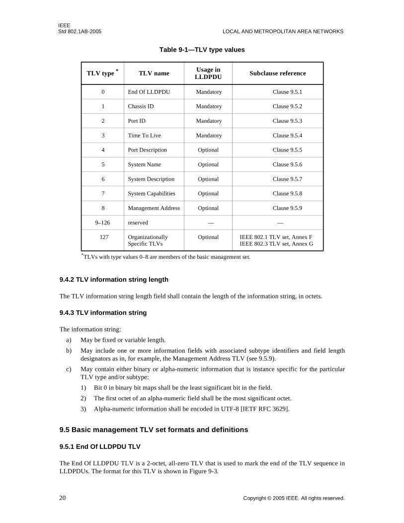
IEEEStd 802.1AB-2005 LOCAL AND METROPOLITAN AREA NETWORKS
9.4.2 TLV information string length
The TLV information string length field shall contain the length of the information string, in octets.
9.4.3 TLV information string
The information string:
a) May be fixed or variable length.
b) May include one or more information fields with associated subtype identifiers and field lengthdesignators as in, for example, the Management Address TLV (see 9.5.9).
c) May contain either binary or alpha-numeric information that is instance specific for the particularTLV type and/or subtype:
1) Bit 0 in binary bit maps shall be the least significant bit in the field.
2) The first octet of an alpha-numeric field shall be the most significant octet.
3) Alpha-numeric information shall be encoded in UTF-8 [IETF RFC 3629].
9.5 Basic management TLV set formats and definitions
9.5.1 End Of LLDPDU TLV
The End Of LLDPDU TLV is a 2-octet, all-zero TLV that is used to mark the end of the TLV sequence inLLDPDUs. The format for this TLV is shown in Figure 9-3.
Table 9-1—TLV type values
TLV type * TLV name Usage in LLDPDU Subclause reference
0 End Of LLDPDU Mandatory Clause 9.5.1
1 Chassis ID Mandatory Clause 9.5.2
2 Port ID Mandatory Clause 9.5.3
3 Time To Live Mandatory Clause 9.5.4
4 Port Description Optional Clause 9.5.5
5 System Name Optional Clause 9.5.6
6 System Description Optional Clause 9.5.7
7 System Capabilities Optional Clause 9.5.8
8 Management Address Optional Clause 9.5.9
9–126 reserved — —
127 Organizationally Specific TLVs
Optional IEEE 802.1 TLV set, Annex FIEEE 802.3 TLV set, Annex G
*TLVs with type values 0–8 are members of the basic management set.
20 Copyright © 2005 IEEE. All rights reserved.
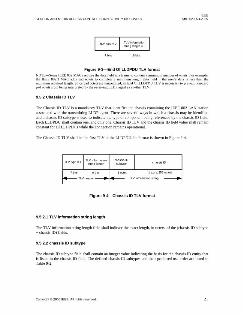
IEEESTATION AND MEDIA ACCESS CONTROL CONNECTIVITY DISCOVERY Std 802.1AB-2005
Figure 9-3—End Of LLDPDU TLV formatNOTE—Some IEEE 802 MACs require the data field in a frame to contain a minimum number of octets. For example,the IEEE 802.3 MAC adds pad octets to complete a minimum length data field if the user’s data is less than theminimum required length. Since pad octets are unspecified, an End Of LLDPDU TLV is necessary to prevent non-zeropad octets from being interpreted by the receiving LLDP agent as another TLV.
9.5.2 Chassis ID TLV
The Chassis ID TLV is a mandatory TLV that identifies the chassis containing the IEEE 802 LAN stationassociated with the transmitting LLDP agent. There are several ways in which a chassis may be identifiedand a chassis ID subtype is used to indicate the type of component being referenced by the chassis ID field.Each LLDPDU shall contain one, and only one, Chassis ID TLV and the chassis ID field value shall remainconstant for all LLDPDUs while the connection remains operational.
The Chassis ID TLV shall be the first TLV in the LLDPDU. Its format is shown in Figure 9-4.
Figure 9-4—Chassis ID TLV format
9.5.2.1 TLV information string length
The TLV information string length field shall indicate the exact length, in octets, of the (chassis ID subtype+ chassis ID) fields.
9.5.2.2 chassis ID subtype
The chassis ID subtype field shall contain an integer value indicating the basis for the chassis ID entity thatis listed in the chassis ID field. The defined chassis ID subtypes and their preferred use order are listed inTable 9-2.
TLV type = 0 TLV informationstring length = 0
9 bits7 bits
TLV header TLV information string
TLV informationstring length chassis ID
chassis IDsubtype
1 < n < 255 octets9 bits7 bits 1 octet
TLV type = 1
Copyright © 2005 IEEE. All rights reserved. 21
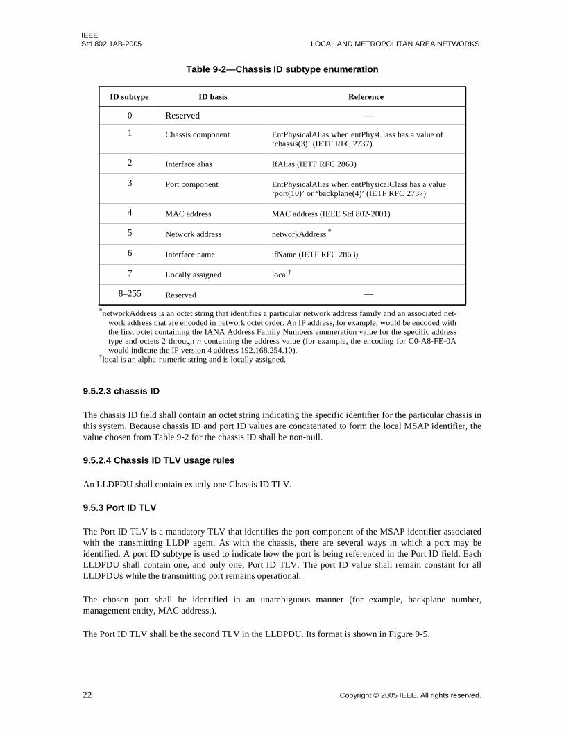
IEEEStd 802.1AB-2005 LOCAL AND METROPOLITAN AREA NETWORKS
9.5.2.3 chassis ID
The chassis ID field shall contain an octet string indicating the specific identifier for the particular chassis inthis system. Because chassis ID and port ID values are concatenated to form the local MSAP identifier, thevalue chosen from Table 9-2 for the chassis ID shall be non-null.
9.5.2.4 Chassis ID TLV usage rules
An LLDPDU shall contain exactly one Chassis ID TLV.
9.5.3 Port ID TLV
The Port ID TLV is a mandatory TLV that identifies the port component of the MSAP identifier associatedwith the transmitting LLDP agent. As with the chassis, there are several ways in which a port may beidentified. A port ID subtype is used to indicate how the port is being referenced in the Port ID field. EachLLDPDU shall contain one, and only one, Port ID TLV. The port ID value shall remain constant for allLLDPDUs while the transmitting port remains operational.
The chosen port shall be identified in an unambiguous manner (for example, backplane number,management entity, MAC address.).
The Port ID TLV shall be the second TLV in the LLDPDU. Its format is shown in Figure 9-5.
Table 9-2—Chassis ID subtype enumeration
ID subtype ID basis Reference
0 Reserved —
1 Chassis component EntPhysicalAlias when entPhysClass has a value of ‘chassis(3)’ (IETF RFC 2737)
2 Interface alias IfAlias (IETF RFC 2863)
3 Port component EntPhysicalAlias when entPhysicalClass has a value ‘port(10)’ or ‘backplane(4)’ (IETF RFC 2737)
4 MAC address MAC address (IEEE Std 802-2001)
5 Network address networkAddress *
6 Interface name ifName (IETF RFC 2863)
7 Locally assigned local†
8–255 Reserved —
*networkAddress is an octet string that identifies a particular network address family and an associated net-work address that are encoded in network octet order. An IP address, for example, would be encoded withthe first octet containing the IANA Address Family Numbers enumeration value for the specific addresstype and octets 2 through n containing the address value (for example, the encoding for C0-A8-FE-0Awould indicate the IP version 4 address 192.168.254.10).
†local is an alpha-numeric string and is locally assigned.
22 Copyright © 2005 IEEE. All rights reserved.

IEEESTATION AND MEDIA ACCESS CONTROL CONNECTIVITY DISCOVERY Std 802.1AB-2005
Figure 9-5—Port ID TLV format
9.5.3.1 TLV information string Length
The TLV information string length field shall indicate the length, in octets, of the (port ID subtype + port ID)fields.
9.5.3.2 port ID subtype
The port ID subtype field shall contain an integer value indicating the basis for the identifier that is listed inthe port ID field. The defined port ID subtypes and their preferred use order are listed in Table 9-3.
Table 9-3—Port ID subtype enumeration
ID subtype ID basis References
0 Reserved —
1 Interface alias ifAlias (IETF RFC 2863)
2 Port component entPhysicalAlias when entPhysicalClass has a value ‘port(10)’ or ‘backplane(4)’ (IETF RFC 2737)
3 MAC address MAC address (IEEE Std 802-2001)
4 Network address networkAddress *
*networkAddress is an octet string that identifies a particular network address family and an asso-ciated network address that are encoded in network octet order. An IP address, for example,would be encoded with the first octet containing the IANA Address Family Numbers enumer-ation value for the specific address type and octets 2 through n containing the address value (forexample, the encoding for C0-A8-FE-0A would indicate the IP version 4 address192.168.254.10).
5 Interface name ifName (IETF RFC 2863)
6 Agent circuit ID agent circuit ID (IETF RFC 3046)
7 Locally assigned local †
†local is an alpha-numeric string and is locally assigned.
8–255 Reserved —
TLV header TLV information string
TLV type = 2TLV information
string length port IDport ID subtype
7 bits 9 bits 1 octet 1 < n < 255 octets
Copyright © 2005 IEEE. All rights reserved. 23
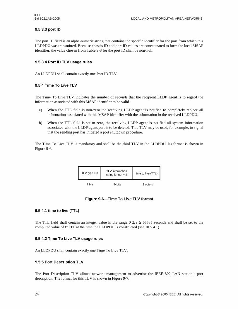
IEEEStd 802.1AB-2005 LOCAL AND METROPOLITAN AREA NETWORKS
9.5.3.3 port ID
The port ID field is an alpha-numeric string that contains the specific identifier for the port from which thisLLDPDU was transmitted. Because chassis ID and port ID values are concatenated to form the local MSAPidentifier, the value chosen from Table 9-3 for the port ID shall be non-null.
9.5.3.4 Port ID TLV usage rules
An LLDPDU shall contain exactly one Port ID TLV.
9.5.4 Time To Live TLV
The Time To Live TLV indicates the number of seconds that the recipient LLDP agent is to regard theinformation associated with this MSAP identifier to be valid.
a) When the TTL field is non-zero the receiving LLDP agent is notified to completely replace allinformation associated with this MSAP identifier with the information in the received LLDPDU.
b) When the TTL field is set to zero, the receiving LLDP agent is notified all system informationassociated with the LLDP agent/port is to be deleted. This TLV may be used, for example, to signalthat the sending port has initiated a port shutdown procedure.
The Time To Live TLV is mandatory and shall be the third TLV in the LLDPDU. Its format is shown inFigure 9-6.
Figure 9-6—Time To Live TLV format
9.5.4.1 time to live (TTL)
The TTL field shall contain an integer value in the range 0 ≤ t ≤ 65535 seconds and shall be set to thecomputed value of txTTL at the time the LLDPDU is constructed (see 10.5.4.1).
9.5.4.2 Time To Live TLV usage rules
An LLDPDU shall contain exactly one Time To Live TLV.
9.5.5 Port Description TLV
The Port Description TLV allows network management to advertise the IEEE 802 LAN station’s portdescription. The format for this TLV is shown in Figure 9-7.
TLV type = 3TLV informationstring length = 2 time to live (TTL)
9 bits7 bits 2 octets
24 Copyright © 2005 IEEE. All rights reserved.
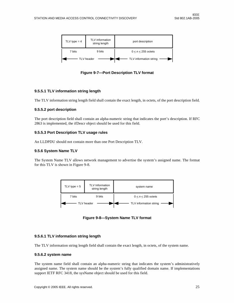
IEEESTATION AND MEDIA ACCESS CONTROL CONNECTIVITY DISCOVERY Std 802.1AB-2005
Figure 9-7—Port Description TLV format
9.5.5.1 TLV information string length
The TLV information string length field shall contain the exact length, in octets, of the port description field.
9.5.5.2 port description
The port description field shall contain an alpha-numeric string that indicates the port’s description. If RFC2863 is implemented, the ifDescr object should be used for this field.
9.5.5.3 Port Description TLV usage rules
An LLDPDU should not contain more than one Port Description TLV.
9.5.6 System Name TLV
The System Name TLV allows network management to advertise the system’s assigned name. The formatfor this TLV is shown in Figure 9-8.
Figure 9-8—System Name TLV format
9.5.6.1 TLV information string length
The TLV information string length field shall contain the exact length, in octets, of the system name.
9.5.6.2 system name
The system name field shall contain an alpha-numeric string that indicates the system’s administrativelyassigned name. The system name should be the system’s fully qualified domain name. If implementationssupport IETF RFC 3418, the sysName object should be used for this field.
TLV header TLV information string
TLV type = 4 TLV informationstring length
port description
7 bits 9 bits 0 < n < 255 octets
TLV header TLV information string
TLV type = 5 TLV Informationstring length
system name
7 bits 9 bits 0 < n < 255 octets
Copyright © 2005 IEEE. All rights reserved. 25

IEEEStd 802.1AB-2005 LOCAL AND METROPOLITAN AREA NETWORKS
9.5.6.3 System Name TLV usage rules
An LLDPDU should not contain more than one System Name TLV.
9.5.7 System Description TLV
The System Description TLV allows network management to advertise the system’s description. The formatfor this TLV is shown in Figure 9-9.
Figure 9-9—System Description TLV format
9.5.7.1 TLV information string length
The TLV information string length field shall indicate the exact length, in octets, of the system description.
9.5.7.2 system description
The system description field shall contain an alpha-numeric string that is the textual description of thenetwork entity. The system description should include the full name and version identification of thesystem's hardware type, software operating system, and networking software. If implementations supportIETF RFC 3418, the sysDescr object should be used for this field.
9.5.7.3 System Description TLV usage rules
An LLDPDU should not contain more than one System Description TLV.
9.5.8 System Capabilities TLV
The System Capabilities TLV is an optional TLV that identifies the primary function(s) of the system andwhether or not these primary functions are enabled. Figure 9-10 shows the format of this TLV.
Figure 9-10—System Capabilities TLV format
TLV header TLV information string
TLV type = 6 TLV informationstring length
system description
7 bits 9 bits 0 < n < 255 octets
TLV header TLV information string
TLV type = 7TLV informationstring length = 4
systemcapabilities
7 bits 9 bits 2 octets
enabledcapabilities
2 octets
26 Copyright © 2005 IEEE. All rights reserved.
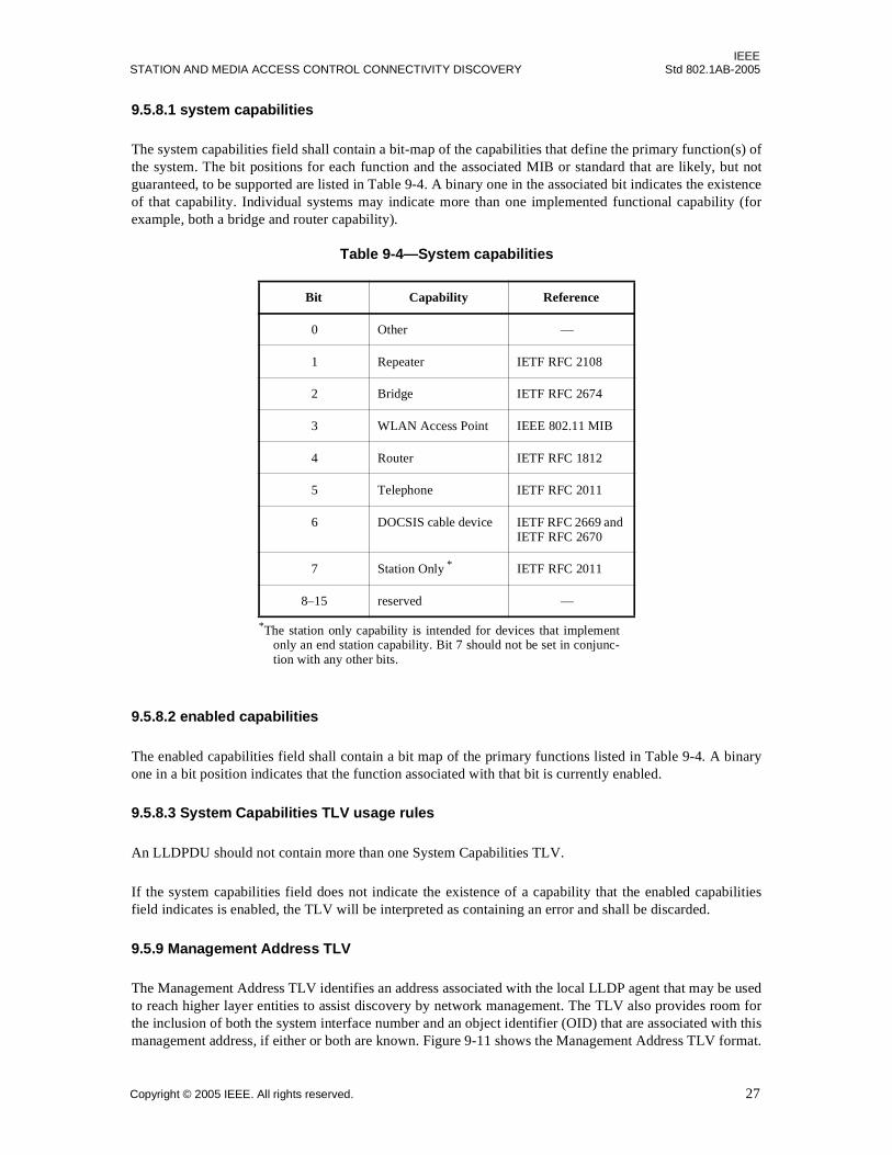
IEEESTATION AND MEDIA ACCESS CONTROL CONNECTIVITY DISCOVERY Std 802.1AB-2005
9.5.8.1 system capabilities
The system capabilities field shall contain a bit-map of the capabilities that define the primary function(s) ofthe system. The bit positions for each function and the associated MIB or standard that are likely, but notguaranteed, to be supported are listed in Table 9-4. A binary one in the associated bit indicates the existenceof that capability. Individual systems may indicate more than one implemented functional capability (forexample, both a bridge and router capability).
9.5.8.2 enabled capabilities
The enabled capabilities field shall contain a bit map of the primary functions listed in Table 9-4. A binaryone in a bit position indicates that the function associated with that bit is currently enabled.
9.5.8.3 System Capabilities TLV usage rules
An LLDPDU should not contain more than one System Capabilities TLV.
If the system capabilities field does not indicate the existence of a capability that the enabled capabilitiesfield indicates is enabled, the TLV will be interpreted as containing an error and shall be discarded.
9.5.9 Management Address TLV
The Management Address TLV identifies an address associated with the local LLDP agent that may be usedto reach higher layer entities to assist discovery by network management. The TLV also provides room forthe inclusion of both the system interface number and an object identifier (OID) that are associated with thismanagement address, if either or both are known. Figure 9-11 shows the Management Address TLV format.
Table 9-4—System capabilities
Bit Capability Reference
0 Other —
1 Repeater IETF RFC 2108
2 Bridge IETF RFC 2674
3 WLAN Access Point IEEE 802.11 MIB
4 Router IETF RFC 1812
5 Telephone IETF RFC 2011
6 DOCSIS cable device IETF RFC 2669 and IETF RFC 2670
7 Station Only *
*The station only capability is intended for devices that implementonly an end station capability. Bit 7 should not be set in conjunc-tion with any other bits.
IETF RFC 2011
8–15 reserved —
Copyright © 2005 IEEE. All rights reserved. 27

IEEEStd 802.1AB-2005 LOCAL AND METROPOLITAN AREA NETWORKS
Figure 9-11—Management Address TLV format
9.5.9.1 TLV information string length
The TLV information string length field shall contain the length, in octets, of all the fields in the TLVinformation string.
9.5.9.2 management address string length
The management address string length field shall contain the length, in octets, of the (management addresssubtype + management address) fields.
9.5.9.3 management address subtype
The management address subtype field shall contain an integer value indicating the type of address that islisted in the management address field. Enumeration for this field is contained in theianaAddressFamilyNumbers module of the IETF RFC 3232 on-line database that is accessible through aweb page (currently, http://www.iana.org). The management address subtype is contained in the first octetof the management address string.
9.5.9.4 management address
The management address field shall contain an octet string indicating the particular management addressassociated with this TLV.
a) The returned address should be the most appropriate for management use, typically a layer 3 addresssuch as the IPv4 address, 192.168.254.10 (see also Table 9-2, footnote 1).
b) If no management address is available, the return address should be the MAC address for the stationor port.
9.5.9.5 interface numbering subtype
The interface numbering subtype field shall contain an integer value indicating the numbering method usedfor defining the interface number. Three values are currently defined:
1) Unknown.
2) ifIndex.
3) system port number.
TLVheader
TLV information string9 < n < 167 octets
TLVtype = 8
TLVinformation
stringlength
managementaddress
managementaddresssubtype
OIDstringlength
objectidentifier
managementaddress string
OID string
7 bits 9 bits 1 octet 1 octet1-31 octets 0-128octets
interfacenumber
interfacenumbering
subtype
4 octets1 octet
managementaddress
string length
1 octet
28 Copyright © 2005 IEEE. All rights reserved.
IEEESTATION AND MEDIA ACCESS CONTROL CONNECTIVITY DISCOVERY Std 802.1AB-2005
9.5.9.6 interface number
The interface number field shall contain the assigned number within the system that identifies the specificinterface associated with this management address. If the value of the interface subtype is unknown, thisfield shall be set to zero.
9.5.9.7 object identifier (OID) string length
The object identifier string length field shall contain the length, in octets, of the OID. A value of zero in thisfield indicates that the OID field is not provided.
9.5.9.8 object identifier
The object identifier field contains an OID that identifies the type of hardware component or protocol entityassociated with the indicated management address. The OID shall be the value portion of the ASN.1encoding of the object identifier [ASN.1]. If no OID is available, this field shall not be provided.
NOTE—The interface number and OID are included in this TLV to assist NMS discovery by indicating EnterpriseSpecific or other starting points for the search, such as the Interface or Entity MIB.
9.5.9.9 Management Address TLV usage rules
Management Address TLVs are subject to the following:
a) At least one Management Address TLV should be included in every LLDPDU.
b) Since there are typically a number of different addresses associated with a MSAP identifier, anindividual LLDPDU may contain more than one Management Address TLV.
c) When Management Address TLV(s) are included in an LLDPDU, the included address(es) shouldbe the address(es) offering the best management capability.
d) If more than one Management Address TLV is included in an LLDPDU, each management addressshall be different from the management address in any other management address TLV in theLLDPDU.
e) If no management address is available, the MAC address may be used.
f) If an OID is included in the TLV, it shall be reachable by the management address.
g) If the network system is a VLAN bridge that implements the port and protocol based VLANclassification, every Management Address TLV that reports an address that is accessible on a portand protocol VLAN through the particular port should be accompanied by a port and protocolVLAN TLV that indicates the VLAN identifier (VID) associated with the management addressreported by this TLV (see F.3.2).
9.6 Organizationally Specific TLVs
This TLV category is provided to allow different organizations, such as IEEE 802.1, IEEE 802.3, IETF, aswell as individual software and equipment vendors, to define TLVs that advertise information to remoteentities attached to the same media, subject to the following restrictions:
a) Information transmitted in an Organizationally Specific TLV is intended to be a one wayadvertisement. The TLV shall not solicit a response and shall not provide an acknowledgement.
b) Information transmitted in an Organizationally Specific TLV shall be independent from informationin a TLV received from a remote port.
c) Information transmitted in one Organizationally Specific TLV shall not be concatenated withinformation transmitted in another TLV on the same media in order to provide a means for sendingmessages that are larger than would fit within a single TLV.
Copyright © 2005 IEEE. All rights reserved. 29
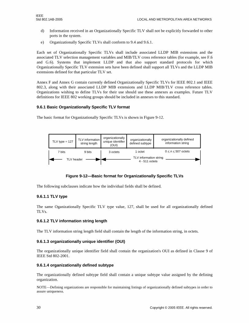
IEEEStd 802.1AB-2005 LOCAL AND METROPOLITAN AREA NETWORKS
d) Information received in an Organizationally Specific TLV shall not be explicitly forwarded to otherports in the system.
e) Organizationally Specific TLVs shall conform to 9.4 and 9.6.1.
Each set of Organizationally Specific TLVs shall include associated LLDP MIB extensions and theassociated TLV selection management variables and MIB/TLV cross reference tables (for example, see F.6and G.6). Systems that implement LLDP and that also support standard protocols for whichOrganizationally Specific TLV extension sets have been defined shall support all TLVs and the LLDP MIBextensions defined for that particular TLV set.
Annex F and Annex G contain currently defined Organizationally Specific TLVs for IEEE 802.1 and IEEE802.3, along with their associated LLDP MIB extensions and LLDP MIB/TLV cross reference tables.Organizations wishing to define TLVs for their use should use these annexes as examples. Future TLVdefinitions for IEEE 802 working groups should be included in annexes to this standard.
9.6.1 Basic Organizationally Specific TLV format
The basic format for Organizationally Specific TLVs is shown in Figure 9-12.
Figure 9-12—Basic format for Organizationally Specific TLVs
The following subclauses indicate how the individual fields shall be defined.
9.6.1.1 TLV type
The same Oganizationally Specific TLV type value, 127, shall be used for all organizationally definedTLVs.
9.6.1.2 TLV information string length
The TLV information string length field shall contain the length of the information string, in octets.
9.6.1.3 organizationally unique identifier (OUI)
The organizationally unique identifier field shall contain the organization's OUI as defined in Clause 9 ofIEEE Std 802-2001.
9.6.1.4 organizationally defined subtype
The organizationally defined subtype field shall contain a unique subtype value assigned by the definingorganization.
NOTE—Defining organizations are responsible for maintaining listings of organizationally defined subtypes in order toassure uniqueness.
TLV header
TLV type = 127TLV information
string length organizationally defined
information string organizationallydefined subtype
3 octets 0 < n < 507 octets
organizationallyunique identifier
(OUI)
1 octet7 bits 9 bits
TLV information string4 - 511 octets
30 Copyright © 2005 IEEE. All rights reserved.
IEEESTATION AND MEDIA ACCESS CONTROL CONNECTIVITY DISCOVERY Std 802.1AB-2005
9.6.1.5 organizationally defined information string
The actual format of the organizationally defined information string field is organizationally specific andcan:
a) Contain either binary or alpha-numeric information that is instance specific for the particular TLVtype and/or subtype. Alpha-numeric information should be encoded in UTF-8 (IETF RFC 3629).
b) Include one or more information fields with their associated field-type identifiers and field lengthdesignators similar to those in the Management Address TLV (see 9.5.9).
9.6.2 Organizationally Specific TLV usage rules
Organizations defining their own Organizationally Specific TLVs should include a subclause that definesany specific usage rules and/or specific conditions that will affect how the receiving LLDP agent shall treatthe TLV.
The Organizationally Specific TLV usage rules should include:
a) The number of Organizationally Specific TLVs that may be contained in an LLDPDU and anyadditional information field subtypes that would identify differences between two TLVs with thesame OUI and organizationally defined subtype (for example, see F.3.3 a).
b) Any error conditions that are specific to the particular Organizationally Specific TLV and the actionthat will be taken for each defined error condition (see F.3.3 b and c).
Copyright © 2005 IEEE. All rights reserved. 31

IEEEStd 802.1AB-2005 LOCAL AND METROPOLITAN AREA NETWORKS
10. The protocol
This clause describes the protocol for a single port where the local LLDP agent manages LLDP operationsfor that port.
The local LLDP agent is responsible for causing the following tasks to be performed:
a) Maintaining current information in the LLDP local system MIB.
b) Extracting and formatting LLDP local system MIB information for transmission to the remote portLLDP agent(s) at regular intervals or whenever there is a change in the system condition or status.
c) Recognizing and processing received LLDP frames.
d) Maintaining current values in the LLDP remote system MIB.
e) Setting the variables somethingChangedLocal and somethingChangedRemote to notify the PTOPOMIB manager and MIB managers of other optional MIBs whenever a value or status change hasoccurred in one or more objects in the LLDP local system LLDP remote systems MIB.
LLDP allows implementations that support three different operating modes: transmit only mode, receiveonly, or both transmit and receive. Implementations of this protocol shall conform to the specifications eachsubclause indicated in Table 10-1 for the operating mode being implemented.
Table 10-1—Subclause/operating mode applicability
Subclause number Subclause title Transmit
onlyReceive
only
Transmit and
receive
10.1.1 LLDP transmit module initialization M*
*M = mandatory
— M
10.2.1 LLDP receive module initialization — M M
10.2 Frame transmission M — M
10.3 Frame reception — M M
10.4 Notational conventions used in state machines M M M
10.5.1 Global variables M M M
10.5.2 Statistical counters M M M
10.5.2.1 Transmission counters M — M
10.5.2.2 Reception counters — M M
10.5.3 Timers M M M
10.5.3.1 Transmit state machine timers M — M
10.5.3.4 Receive state machine timers — M M
10.5.3.3 Transmit state machine timing parameters M — M
10.5.3.4 Receive state machine timing parameters — M M
10.5.4 Transmit state machine M — M
10.5.5 Receive state machine — M M
32 Copyright © 2005 IEEE. All rights reserved.
IEEESTATION AND MEDIA ACCESS CONTROL CONNECTIVITY DISCOVERY Std 802.1AB-2005
10.1 Protocol initialization
Because the local LLDP agent may be configured to both transmit and receive LLDP frames, to onlytransmit LLDP frames, or to only receive LLDP frames, separate protocol initialization processes are neededfor frame transmission and reception.
10.1.1 LLDP transmit module initialization
During LLDP initialization or re-initialization of the transmit module, the local LLDP agent shall performthe following tasks:
a) If applicable, either the non-volatile configuration for the LLDP local system MIB shall be retrievedor the appropriate default values shall be assigned to all LLDP configuration variables.
b) The internal (implementation specific) data structures shall be initialized with appropriate localphysical topology information.
c) The variable somethingChangedLocal shall be set to FALSE
d) Appropriate values shall be set for the following timing parameters:
1) reinitDelay.
2) msgTxHold.
3) msgTxInterval.
4) txDelay.
e) The variable adminStatus shall be interrogated to determine whether initialization should proceedfurther. If the value of adminStatus is ‘disabled’, LLDP transmit module initialization shall be halteduntil the variable portEnabled is equal to TRUE and the value of adminStatus is either of thefollowing:
1) enabledTxRx: the local LLDP agent can both transmit and receive LLDP frames.
2) enabledTxOnly: the local LLDP agent can only transmit LLDP frames.
NOTE—It is both permissible and recommended to introduce a degree of stagger into starting the LLDP local agentinitialization in multi-port implementations so that the timing of LLDP frame transmission cycles can be distributedamong system ports. The method of accomplishing the stagger is an implementation issue and is beyond the scope ofthis standard.
10.1.2 LLDP receive module initialization
After the variable portEnabled is equal to TRUE, the LLDP receive module is initialized or re-initialized forframe reception. During this process, the local LLDP agent shall perform the following tasks:
a) The variable tooManyNeighbors shall be set to FALSE.
b) The adminStatus object shall be interrogated to determine whether initialization should proceedfurther. If the value of adminStatus is ‘disabled’, LLDP receive initialization shall be halted until thevalue of adminStatus is one of the following:
1) enabledTxRx: the local LLDP agent can both transmit and receive LLDP frames.
2) enabledRxOnly: the local LLDP agent can only receive LLDP frames.
c) All information in the remote systems MIB associated with this port shall be deleted.
10.2 Frame transmission
Frame transmission is a combined responsibility of the LLDP MIB manager and the LLDP transmit module.LLDP transmission shall conform to the following:
Copyright © 2005 IEEE. All rights reserved. 33

IEEEStd 802.1AB-2005 LOCAL AND METROPOLITAN AREA NETWORKS
a) An active LLDP agent enabled for transmission shall initiate an LLDP frame transmission whenevereither of the following events occur:
1) Expiration of the transmission countdown timing counter, txTTR, associated with the LLDPlocal system MIB.
2) A condition (status or value) change in one or more objects in the LLDP local system MIB.
b) To prevent a series of successive LLDP frame transmissions during a short period due to rapidchanges in LLDP local systems MIB objects and to increase the probability that multiple, rather thansingle changes are reported in each frame, the local LLDP shall limit the LLDP frame transmissionrate through use of a variable transmit delay timer that may be set by network management.
c) The LLDP agent shall suppress the transmission of multiple frames during a single transmissioncycle if frame transmission cannot be restricted to a single port, but rather is transmitted through agroup of ports attached to the same LAN segment (for example, in a repeater). In this case, a singleport in the port group should be selected (in an implementation specific manner) to represent theport group. An LLDP agent should represent port groups as “backplanes”, in the LLDP local systemMIB (and in the entPhysicalTable of the Entity MIB, rather than individual ports in either the EntityMIB or Interfaces MIB).
d) Actual transmission intervals for different ports on the same multi-port implementation should bestaggered to prevent synchronization effects.
10.2.1 LLDPDU construction
Two types of LLDPDUs are defined:
a) Normal LLDPDUs where the purpose is to provide management information about the local station.
b) A special shutdown advisory LLDPDU indicating that the information about the local station that ismaintained in the remote LLDP agent’s remote systems MIB is about to become invalid.
10.2.1.1 Normal LLDPDU construction
The LLDP local system MIB shall contain the information needed for constructing individual TLVs andshall include a capability that will allow network managers to select which optional TLVs are to be includedin the LLDPDU (see 11.2.2).
When a new transmission cycle is indicated for an LLDP enabled port, the LLDP MIB manager shall extractthe selected information from the LLDP local system MIB and shall construct an LLDPDU as defined in9.1, containing:
a) Three mandatory TLVs as specified in 9.2:
1) Chassis ID TLV (see 9.5.2).
2) Port ID TLV (see 9.5.3).
3) Time To Live TLV, with the TTL value set equal to txTTL (see 9.5.4).
b) Additional optional TLVs from either the basic management set or from one or moreorganizationally specific sets, as allowed by LLDPDU length restrictions and as selected in theLLDP local system MIB by network management (see Table 9-1, Table F-1, and Table G-1).
c) An End Of LLDPDU TLV.
Optional TLVs from the basic management set, such as the Management Address TLV, with different TLVtype and subtype combinations as well as optional TLVs with different OUI and organizationally definedsubtype combinations from one or more organizationally specific sets may be included within the sameLLDPDU.
34 Copyright © 2005 IEEE. All rights reserved.
IEEESTATION AND MEDIA ACCESS CONTROL CONNECTIVITY DISCOVERY Std 802.1AB-2005
When the LLDPDU is complete, the MIB manager shall re-initialize the txTTR timing counter in the LLDPlocal system MIB.
10.2.1.2 Shutdown LLDPDU construction
A special procedure exists for the case in which a LLDP agent knows an associated port is about to becomenon-operational (for example, the adminStatus for the port is transitioning to ‘disabled’). In the event a port,currently configured with LLDP frame transmission enabled, either becomes disabled for LLDP activity, orthe interface is administratively disabled, a final LLDP shutdown LLDPDU may be sent with:
1) The Chassis ID and Port ID TLVs.
2) The Time To Live TLV with the TTL field set to zero.
3) An End Of LLDPDU TLV.
The LLDPDU shall not include any optional TLVs and should be transmitted before the interface isdisabled.
NOTE—There is an inherent race condition between an interface knowing it is going down and its ability to send “onemore frame.” If possible, the actual termination of the connection should be delayed until after this frame is transmitted.In the event where adminStatus is transitioning to the disabled state and the LLDP agent will be shutting down, then thisshutdown procedure should be executed for all local ports.
10.2.2 LLDP frame formatting/transmission
Upon receipt of an LLDPDU, the LLDP transmission module shall:
a) Prepend the appropriate source and destination addresses plus the LLDP Ethertype to the LLDPDUas defined in 8.1, 8.2, and 8.3 to complete the construction of the MA_UNITDATA.request.
b) Utilize the services of the LLC to pass the MA_UNITDATA.request to the MAC for final frameformatting and transmission.
c) Increment the statsFramesOutTotal counter.
10.3 Frame reception
LLDP frame reception consists of three phases: frame recognition, frame validation, and LLDP remotesystems MIB updating. All error checking is done during frame validation.
10.3.1 LLDP frame recognition
The frame recognition is done at the LLDP/LSAP (see Figure 6-2) where the following frame elements shallbe checked to determine whether:
a) The destination address value is the assigned LLDP_Multicast address defined in 8.1.
b) The Ethertype value is the LLDP Ethertype defined in 8.3 for the particular frame format.
If both of the above conditions are TRUE, the global variable rcvFrame shall be set to TRUE and the frameshall be sent to the LLDP receive module for validation.
10.3.2 LLDPDU validation
The receive module shall process each incoming LLDPDU as it is received. The statsFramesInTotal counterfor the port shall be incremented and the LLDPDU shall be checked to verify the presence of the threemandatory TLVs at the beginning of the LLDPDU as defined in 9.2.
a) The first TLV shall be extracted:
1) If the extracted TLV type value does not equal 1, the TLV is not a Chassis ID TLV:
Copyright © 2005 IEEE. All rights reserved. 35
IEEEStd 802.1AB-2005 LOCAL AND METROPOLITAN AREA NETWORKS
i) The LLDPDU shall be discarded.
ii) The statsFramesDiscardedTotal and statsFramesInErrorsTotal counters shall both beincremented.
iii) The variable badFrame shall be set to TRUE.
iv) The procedure rxProcessFrame() shall be terminated.
2) If the extracted TLV type value equals 1, and the chassis ID TLV information string length isnot within the range 2 < n < 256:
i) The LLDPDU shall be discarded.
ii) The statsFramesDiscardedTotal and statsFramesInErrorsTotal counters shall both beincremented.
iii) The variable badFrame shall be set to TRUE.
iv) The procedure rxProcessFrame() shall be terminated.
3) If the extracted TLV type value equals 1, and the chassis ID TLV information string length iswithin the range 2 < n < 256, the chassis ID value shall be extracted to become the first part ofthe MSAP identifier.
b) The second TLV shall be extracted:
1) If the extracted TLV type value does not equal 2, the TLV is not a Port ID TLV:
i) The LLDPDU shall be discarded.
ii) The statsFramesDiscardedTotal and statsFramesInErrorsTotal counters shall both beincremented.
iii) The variable badFrame shall be set to TRUE.
iv) The procedure rxProcessFrame() shall be terminated.
2) If the extracted TLV type value equals 2, and the port ID TLV information string length is notwithin the range 2 < n < 256:
i) The LLDPDU shall be discarded.
ii) The statsFramesDiscardedTotal and statsFramesInErrorsTotal counters shall both beincremented.
iii) The variable badFrame shall be set to TRUE.
iv) The procedure rxProcessFrame() shall be terminated.
3) If the extracted TLV type value equals 2, and the port ID TLV information string length iswithin the range 2 < n < 256, the port ID value shall be extracted and appended to thechassis ID value to complete construction of the MSAP identifier.
c) The third TLV shall be extracted:
1) If the extracted TLV type value does not equal 3, the TLV is not a Time To Live TLV.
i) The LLDPDU shall be discarded.
ii) The statsFramesDiscardedTotal and statsFramesInErrorsTotal counters shall both beincremented.
iii) The variable badFrame shall be set to TRUE.
iv) The procedure rxProcessFrame() shall be terminated.
2) If the extracted TLV type value equals 3, and the Time To Live TLV information string lengthis less than 2:
i) The LLDPDU shall be discarded.
ii) The statsFramesDiscardedTotal and statsFramesInErrorsTotal counters shall both beincremented.
iii) The variable badFrame shall be set to TRUE.
iv) The procedure rxProcessFrame() shall be terminated.
36 Copyright © 2005 IEEE. All rights reserved.

IEEESTATION AND MEDIA ACCESS CONTROL CONNECTIVITY DISCOVERY Std 802.1AB-2005
3) If the extracted TLV type value equals 3, and the Time To Live TLV information string lengthis greater than or equal to 2, the first two octets of the TLV information string shall be extractedand rxTTL shall be set to this value:
i) If rxTTL equals zero, a shutdown frame has been received. The MSAP identifier andrxTTL shall be passed up to the LLDP MIB manager, and further LLDPDU validationshall be terminated.
ii) If rxTTL is non-zero, LLDPDU validation shall continue and the remaining TLVs shall bevalidated.
Each of the remaining TLV information elements shall be decoded in succession as required by theirparticular TLV format definitions:
d) If the TLV type value equals 0, the TLV is the End Of LLDPDU TLV. The MSAP identifier,rxTTL, and all validated TLVs shall be passed to the LLDP manager for LLDP remote systems MIBupdating.
e) If (0 < TLV_type_value < 8) the TLV is a member of the basic management set and shall bevalidated according to the general rules for all TLVs defined in 10.3.2.1 as well as any specific rulesdefined for the particular TLVs defined in 9.5.
f) If TLV_type_value is in the range of reserved TLV types in Table 9-1, the TLV is unrecognized andmay be a basic TLV from a later LLDP version. The statsTLVsUnrecognizedTotal counter shall beincremented, and the TLV shall be assumed to be validated.
g) If the TLV type value is 127, the TLV is an Organizationally Specific TLV:
1) If the TLV’s OUI and organizationally defined subtype are recognized, the TLV shall bevalidated according to the general rules for all TLVs defined in 10.3.2.1 as well as the generalrules for Organizationally Specific TLVs defined in 10.3.2.2 plus any specific rules defined forthe particular TLV (see Annex F for IEEE 802.1 TLVs and Annex G for IEEE 802.3 TLVs).
2) If the TLV’s OUI and/or organizationally defined subtype are not recognized, thestatsTLVsUnrecognizedTotal counter shall be incremented, and the TLV shall be assumed tobe validated.
h) If the end of the LLDPDU has been reached, the MSAP identifier, rxTTL, and all validated TLVsshall be passed to the LLDP manager for LLDP remote systems MIB updating.
10.3.2.1 General validation rules for all TLVs
The value in the TLV information string length field shall be the value that is used to validate the TLV andto indicate the location of the next TLV in the LLDPDU.
All TLVs shall conform to the general validation rules listed in this subclause as well as any specific usagerules defined for the particular TLV (for example, see systems capabilities TLV usage rules in 9.5.8.3):
a) If the LLDPDU contains more than one Chassis ID TLV, Port ID TLV, or Time To Live TLV:
1) The LLDPDU shall be discarded.
2) The statsFramesDiscardedTotal and statsFramesInErrorsTotal counters shall both beincremented.
b) If the TLV information string length value is greater than the sum of the lengths of all fieldscontained in the TLV information string:
1) The extra octets shall be ignored.
2) The location of the next TLV shall be based on the TLV information string length value of thecurrent TLV.
c) If the TLV information string length value is less than the sum of the lengths of the contained fields,the location of the next TLV is indeterminate:
Copyright © 2005 IEEE. All rights reserved. 37
IEEEStd 802.1AB-2005 LOCAL AND METROPOLITAN AREA NETWORKS
1) The LLDPDU shall be discarded.
2) The statsFramesDiscardedTotal and statsFramesInErrorsTotal counters shall both beincremented.
d) If any TLV contains an error condition specified for that particular TLV (for example, see F.3.3):
1) The TLV shall be discarded.
2) The statsTLVsDiscardedTotal and statsFramesInErrorsTotal counters shall both beincremented.
3) The location of the next TLV shall be based on the TLV information string length value of thecurrent TLV.
e) If any TLV extends past the physical end of the frame:
1) The TLV shall be discarded.
2) The statsTLVsDiscardedTotal and statsFramesInErrorsTotal counters shall both beincremented.
f) Any information following an End Of LLDPDU TLV shall be ignored.
NOTE—Usage rules for individual TLVs allow some TLVs to appear more than once in an LLDPDU. Duplicate TLVsmay result in any one of the values being placed in the MIB, may but will not necessarily cause the discard stats toincrement, and may cause the change marker for the MIB entry to change if any of the TLV copies change the valueeven if the value finally recorded is unchanged. The only thing guaranteed is that the MIB value will be set to one(unspecified) of the TLV values, and if that value is different to what was previously in the MIB then the change markerwill be set.
10.3.2.2 General validation rules for all Organizationally Specific TLVs
If an Organizationally Specific TLV is not recognized by the receiving LLDP agent, the content of the TLVcan be ignored but the TLV shall be stored in the LLDP remote systems MIB for possible retrieval bynetwork management using the basic Organizationally Specific TLV format (see 9.6). If more than oneunrecognized Organizationally Specific TLV is received with the same OUI and organizationally definedsubtype, but with identifiable differences in the organizationally defined information strings, all copies shallbe assigned a temporary identification index and stored.
10.3.3 TLV/MIB object value comparison
The LLDP MIB manager is responsible for updating and maintaining each LLDP remote systems MIBassociated with the LLDP agent. It uses one control variable somethingChangedRemote to track when anychange has occurred in the LLDP remote systems MIB due to new or different information in the TLVs froman incoming LLDPDU.
When an LLDPDU is passed up from the LLDP receive module, the LLDP MIB manager shall:
a) Set the flag variable somethingChangedRemote associated with the MSAP identifier to FALSE.
b) If rxTTL is zero, delete all information associated with the MSAP identifier from the LLDP remotesystems MIB, set the variable somethingChangedRemote to TRUE, and wait for the next LLDPDU.
c) If rxTTL is non-zero and the LLDPDU’s MSAP identifier is not associated with an existing LLDPremote systems MIB, check to determine if sufficient space exists in the LLDP remote systems MIBto accommodate the current LLDPDU:
1) If sufficient space exists, perform the LLDP remote systems MIB update procedure defined in10.3.5.
2) If sufficient space does not exist, perform the “Too many neighbors” process defined in 10.3.4.
d) If rxTTL is non-zero and the LLDPDU’s MSAP identifier is associated with an existing LLDPremote systems MIB, compare all current information in the LLDP remote systems MIB with theinformation in the TLVs just received:
38 Copyright © 2005 IEEE. All rights reserved.
IEEESTATION AND MEDIA ACCESS CONTROL CONNECTIVITY DISCOVERY Std 802.1AB-2005
1) If no differences are found, set the control variable rxChanges to FALSE, set the timing counterrxInfoTTL associated with the MSAP identifier to rxTTL, and wait for the next LLDPDU.
2) If any differences are found and there is sufficient space in the LLDP remote systems MIB tostore the new LLDPDU, set the control variable rxChanges to TRUE and perform the LLDPremote systems MIB update process defined in 10.3.5.
3) If differences are found but there is not sufficient space to store the new LLDPDU, perform the“Too many neighbors” process defined in 10.3.4.
10.3.4 Too many neighbors
The amount of space needed in the LLDP remote systems MIB to accommodate the creation of several newMIB structures is beyond the scope of this standard. It may not always be possible to accommodate anothernew neighbor in implementations with limited memory. There are several possibilities for handling thiscase, including but not limited to the following examples:
a) Ignore and not process the new neighbor’s information.
b) Delete the information from the oldest neighbor(s) until there is sufficient memory available to storethe new neighbor’s information.
c) Randomly delete neighbors until there is sufficient memory available to store the new neighbor’sinformation.
The method of handling the case where a new entry in the remote systems MIB can not be created is beyondthe scope of this standard, however it is necessary for the implementation to keep track of this case byproperly updating the variable tooManyNeighbors and the tooManyNeighborsTimer. The variable tooMany-Neighbors identifies when there is insufficient space in the LLDP remote systems MIB to store informationfrom all active neighbors. The tooManyNeighborsTimer indicates the minimum time that this condition willexist.
When there is insufficient space in the LLDP remote systems MIB to store information from a new neighborsomething needs to be discarded. Either the received LLDPDU is discarded or existing information withinthe current remote systems MIB is discarded in order to make space for the new information received in theLLDPDU:
d) Set the flag variable tooManyNeighbors to TRUE.
e) If the information selected to be discarded is the information in the current LLDPDU:
1) Set the tooManyNeighborsTimer as follows:
tooManyNeighborsTimer = max (tooManyNeighborsTimer, rxTTL) (1)
where rxTTL is the TTL value in the current LLDPDU
2) Discard the current LLDPDU and increment the statsFramesDiscardedTotal counter.
3) Wait for the next LLDPDU.
f) If the information selected to be discarded is currently in the LLDP remote systems MIB:
1) Delete all information associated with the selected neighbor’s MSAP identifier from the LLDPremote systems MIB.
2) Set the tooManyNeighborsTimer as follows:
tooManyNeighborsTimer = max (tooManyNeighborsTimer, rxInfoTTL) (2)
where: rxInfoTTL = the selected neighbor’s TTL value
3) If sufficient space exists to store the information received in the current LLDPDU in the LLDPremote systems MIB, perform the MIB update process defined in 10.3.5.
Copyright © 2005 IEEE. All rights reserved. 39
IEEEStd 802.1AB-2005 LOCAL AND METROPOLITAN AREA NETWORKS
4) If sufficient space still does not exist to store the information received in the current LLDPDUin the LLDP remote systems MIB, perform steps 1–3 again.
The variable tooManyNeighbors shall be automatically set to FALSE whenever the tooManyNeigh-borsTimer expires.
NOTE—To prevent numerous unnecessary deletions and additions to the PTOPO and other optional MIBs, during timeswhen there are too many neighbors for the space available in the LLDP remote systems MIBs, the flag variablesomethingChangedRemote associated with the deleted MIB information will not be set to TRUE. Rather, the associatedMIB objects in the PTOPO and other MIBS will be allowed to age out.
10.3.5 LLDP remote systems MIB update
MIB space is available and an LLDP remote systems MIB update is needed:
a) Compare the MSAP identifier in the current LLDPDU with the MSAP identifiers in the LLDPremote systems MIB:
1) If a match is found, replace all current information associated with the MSAP identifier in theLLDP remote systems MIB with the information in the current LLDPDU.
2) If no match is found, create a new MIB structure to receive information associated with the newMSAP identifier, and set these MIB objects to the values indicated in their respective TLVs.
b) Set the timing counter rxInfoTTL associated with the MSAP identifier to rxTTL.
c) Set the flag variable somethingChangedRemote associated with the MSAP identifier to TRUE tonotify the managers of PTOPO and other optional MIBs that something has changed in the LLDPremote systems MIB associated with that MSAP identifier.
If an incoming TLV is not recognized by the receiving LLDP agent, the TLV shall be stored in the LLDPremote systems MIB as follows:
d) If the TLV type value is in the range of the reserved TLV types in Table 9-1, the TLV may be froma later version of the basic management set and shall be stored according to the basic TLV formatshown in Figure 9-2. These TLVs shall be indexed by their TLV type.
e) If the TLV type value is 127, the TLV is an Organizationally Specific TLV and shall be storedaccording to the basic format for Organizationally Specific TLVs shown in Figure 9-12. TheseTLVs shall be indexed by their OUI and organizationally defined TLV subtype.
10.3.6 LLDP remote systems rxInfoTTL timer expiration
If rxInfoTTL timer associated with an MSAP identifier expires, all information associated with that MSAPidentifier shall be deleted and the flag variable somethingChangedRemote associated with the MSAPidentifier shall be set to TRUE to notify the managers of IETF optional MIBs that something has changed inthe LLDP remote systems MIB associated with that MSAP identifier.
10.3.7 LLDP local port/connection failure
If the local port or the connection to the remote system fails before a shutdown frame can be sent, the LLDPmanager shall not delete objects in the LLDP remote systems MIB pertaining to information received fromany MSAP identifier through that local port until the port is re-initialized or the associated rxInfoTTL timerexpires.
10.4 Notational conventions used in state diagrams.
State diagrams are used to represent the operation of a function as a group of connected, mutually exclusivestates. Only one state of a function can be active at any given time.
40 Copyright © 2005 IEEE. All rights reserved.
IEEESTATION AND MEDIA ACCESS CONTROL CONNECTIVITY DISCOVERY Std 802.1AB-2005
Each state is represented in the state diagram as a rectangular box, divided into two parts by a horizontalline. The upper part contains the state identifier, written in uppercase letters. The lower part contains anyprocedures that are executed on entry to the state.
All permissible transitions between states are represented by arrows, the arrowhead denoting the direction ofthe possible transition. Labels attached to arrows denote the condition(s) that shall be met in order for thetransition to take place. A transition that is global in nature (i.e., a transition that occurs from any of thepossible states if the condition attached to the arrow is met) is denoted by an open arrow; i.e., no specificstate is identified as the origin of the transition.
On entry to a state, the procedures defined for the state (if any) are executed exactly once, in the order thatthey appear on the page. Each action is deemed to be atomic; i.e., execution of a procedure completes beforethe next sequential procedure starts to execute. No procedures execute outside of a state block. Oncompletion of all of the procedures within a state, all exit conditions for the state (including all conditionsassociated with global transitions) are evaluated continuously until such a time as one of the conditions ismet. All exit conditions are regarded as Boolean expressions that evaluate to TRUE or FALSE; if acondition evaluates to True, then the condition is met. When the condition associated with a global transitionis met, it supersedes all other exit conditions, including UCT. The label UCT denotes an unconditionaltransition (i.e., UCT always evaluates to True). The label ELSE denotes a transition that occurs if none ofthe other conditions for transitions from the state are met (i.e., ELSE evaluates to TRUE if all other possibleexit conditions from the state evaluate to FALSE).
A variable that is set to a particular value in a state block retains this value until a subsequent state blockexecutes a procedure that modifies the value.
Where it is necessary to segment a state machine description across more than one diagram, a transitionbetween two states that appear on different diagrams is represented by an exit arrow drawn with dashedlines, plus a reference to the diagram that contains the destination state. Similarly, dashed arrows and adashed state box are used on the destination diagram to show the transition to the destination state. In a statemachine that has been segmented in this way, any global transitions that can cause entry to states defined inone of the diagrams are deemed to be potential exit conditions for all of the states of the state machine,regardless of which diagram the state boxes appear in.
Should a conflict exist between the interpretation of a state diagram and either the corresponding globaltransition tables or the textual description associated with the state machine, the state diagram takesprecedence.
The interpretation of the special symbols and operators used in the state diagrams is defined in Table 10-2;these symbols and operators are derived from the notation of the “C” programming language, ANSI X3.159.
Copyright © 2005 IEEE. All rights reserved. 41

IEEEStd 802.1AB-2005 LOCAL AND METROPOLITAN AREA NETWORKS
Table 10-2—State machine symbols
Symbol Interpretation
( ) Used to force the precedence of operators in Boolean expressions and to delimit the argument(s) of actions within state boxes.
; Used as a terminating delimiter for actions within state boxes. Where a state box contains multi-ple actions, the order of execution follows the normal English language conventions for reading text.
= Assignment action. The value of the expression to the right of the operator is assigned to the variable to the left of the operator. Where this operator is used to define multiple assignments, e.g., a = b = Xthe action causes the value of the expression following the right-most assignment operator to be assigned to all of the variables that appear to the left of the right-most assignment operator.
! Logical NOT operator.
&& Logical AND operator.
|| Logical OR operator.
if...then... Conditional action. If the Boolean expression following the if evaluates to TRUE, then the action following the then is executed.
{statement 1, ... statement N}
Compound statement. Braces are used to group statements that are executed together as if they were a single statement.
!= Inequality. Evaluates to TRUE if the expression to the left of the operator is not equal in value to the expression to the right.
== Equality. Evaluates to TRUE if the expression to the left of the operator is equal in value to the expression to the right.
< Less than. Evaluates to TRUE if the value of the expression to the left of the operator is less than the value of the expression to the right.
> Greater than. Evaluates to TRUE if the value of the expression to the left of the operator is greater than the value of the expression to the right.
>= Greater than or equal to. Evaluates to TRUE if the value of the expression to the left of the oper-ator is either greater than or equal to the value of the expression to the right.
+ Arithmetic addition operator.
– Arithmetic subtraction operator.
42 Copyright © 2005 IEEE. All rights reserved.

IEEESTATION AND MEDIA ACCESS CONTROL CONNECTIVITY DISCOVERY Std 802.1AB-2005
10.5 State machines
The operation of the protocol can be represented with two simple state machines and associated timingcounters to indicate when local system managed object values need to be sent to refresh the values in remoteLLDP agent’s LLDP remote systems MIB and when object values in the local LLDP agent’s remote systemsMIB will become invalid:
a) Transmit state machine.
b) Receive state machine.
10.5.1 Global variables
Global variables are available for use by more than one state machine, and are used to perform inter-state-machine communication and initialization functions.
a) adminStatus: This is a per-port variable that indicates whether or not the local LLDP agent isenabled. The defined values for this variable are:
1) enabledRxTx: the local LLDP agent can both transmit and receive LLDP frames through theport. ‘enabledRxTx’ is the adminStatus recommended default value.
2) enabledTxOnly: the local LLDP agent can only transmit LLDP frames.
3) enabledRxOnly: the local LLDP agent can only receive LLDP frames.
4) disabled: the local LLDP agent can neither transmit or receive LLDP frames.
b) portEnabled: This variable is externally controlled. Its value reflects the operational state of theMAC service supporting the port. Its value is TRUE if the MAC service supporting the port is in anoperable condition, otherwise it is FALSE.
10.5.2 Statistical counters
Statistical counters shall be provided to accumulate operational statistics on a per-port basis.
10.5.2.1 Transmission counters
The following counter has been defined for the transmit state machine:
a) statsFramesOutTotal: This counter provides a count of all LLDP frames transmitted.
10.5.2.2 Reception counters
The following counters have been defined for the receive state machine:
a) statsAgeoutsTotal: This counter provides a count of the times that a neighbor’s information hasbeen deleted from the LLDP remote systems MIB because the rxInfoTTL timer associated with theneighbor’s MSAP has expired.
b) statsFramesDiscardedTotal: This counter provides a count of all LLDPDUs received and then dis-carded for any of the following reasons:
1) One or more of the three mandatory TLVs at the beginning of the LLDPDU is missing, out oforder or contains an out of range information string length.
2) There is insufficient space in the remote systems MIB to store the LLDPDU.
c) statsFramesInErrorsTotal: This counter provides a count of all LLDPDUs received with one ormore detectable errors.
d) statsFramesInTotal: This counter provides a count of all LLDP frames received.
e) statsTLVsDiscardedTotal: This counter provides a count of all TLVs received and then discardedfor any reason.
Copyright © 2005 IEEE. All rights reserved. 43
IEEEStd 802.1AB-2005 LOCAL AND METROPOLITAN AREA NETWORKS
f) statsTLVsUnrecognizedTotal: This counter provides a count of all TLVs received on the port thatare not recognized by the LLDP local agent.
All statistical counters shall be four octets long. Counter values shall be maintained in the LLDP localcontrol MIB on a continuing basis and shall not be deleted upon expiration of rxInfoTTL timing counters inthe LLDP remote systems MIB or upon the receipt of a shutdown frame from a remote LLDP agent.
10.5.3 Timers
The timer used for LLDP state machines decrements countdown counters that keep time values for the allobjects in the resident station’s LLDP MIB. All counters shall:
a) Have a resolution of one second.
b) Have an integer value n, where 0 < n < 65535 seconds.
c) Be started by loading an initial integer value.
d) Be decremented once per second as long as n > 0.
e) Represent the remaining time in the period.
10.5.3.1 Transmit state machine timers
The following timing counters have been defined for the transmit state machine:
a) txShutdownWhile: This timer indicates the number of seconds remaining until LLDP re-initializa-tion can occur.
b) txDelayWhile: This timer introduces a minimum delay between transmission of successive LLDPframes.
c) txTTR: The transmit time to refresh timer indicates the number of seconds remaining until the localLLDP agent needs to send a new frame containing information from the LLDP local systems MIB torefresh the information in the remote LLDP agent’s remote systems MIB.
10.5.3.2 Receive state machine timers
The following timing counters have been defined for the receive state machine:
a) rxInfoTTL: This timer indicates the number of seconds remaining until the information in all theobjects in the LLDP remote systems MIB associated with the MSAP identifier will no longer bevalid and need to be deleted.
b) TooManyNeighborsTimer: This timer indicates the number of seconds remaining during which itis known that an LLDP neighbor exists that may not be stored in the remote systems MIB.
10.5.3.3 Transmit state machine timing parameters
The following timing counters are used in conjunction with the timers defined in 10.5.3.1:
a) msgTxHold: This parameter is a multiplier on the msgTxInterval that determines the actual TTLvalue used in an LLDPDU. The recommended default value for msgTxHold is 4.
b) msgTxInterval: This parameter indicates the interval at which LLDP frames are transmitted onbehalf of this LLDP agent. The recommended default value for msgTxInterval is 30 seconds.
c) reinitDelay: This parameter indicates the amount of delay from when adminStatus becomes“disabled’ until re-initialization will be attempted. The recommended default value for reinitDelay is2 seconds.
d) txDelay: This parameter indicates the delay between successive LLDP frame transmissions initiatedby value or status changes in the LLDP local systems MIB. The value for txDelay is set by thefollowing range formula:
44 Copyright © 2005 IEEE. All rights reserved.

IEEESTATION AND MEDIA ACCESS CONTROL CONNECTIVITY DISCOVERY Std 802.1AB-2005
1 < txDelay < (0.25 × msgTxInterval) (3)
The recommended default value for txDelay is 2 seconds.
10.5.3.4 Receive state machine timing parameters
There are no receive state machine timing parameters associated with the timers defined in 10.5.3.2.
10.5.4 Transmit state machine
The transmit state machine is used to format TLVs and to construct LLDPDUs with information extractedfrom MIB objects in the LLDP local system MIB.
10.5.4.1 Transmit state machine variables
a) somethingChangedLocal: This variable indicates that the status/value of one or more of theselected objects in the LLDP local system MIB has changed. It is also used as a flag to notify themanagers of the PTOPO and other optional MIB that something has changed in the LLDP localsystems MIB.
b) txTTL: This variable indicates the time remaining before information in the outgoing LLDPDUwill no longer be valid. The TTL field in the Time To Live TLV is set to txTTL during LLDPDUconstruction (see 10.2.1.1). The value of txTTL depends on the following:
1) During normal operation, txTTL is set according to the following:
(msgTxInterval × msgTxHold) < txTTL < 65535 (4)
2) If adminStatus is transitioning to ‘disabled’ or portEnabled is transitioning to FALSE, txTTLshall be set to zero.
10.5.4.2 Transmit state machine procedures
Four procedures are defined for the transmit state machine.
10.5.4.2.1 mibConstrInfoLLDPDU ()
The mibConstrInfoLLDPDU () procedure constructs an information LLDPDU as defined in 10.2.1.1according to the LLDPDU and associated basic TLV formats as specified in 9.2 and 9.4 plus any optionalOrganizationally Specific TLVs as specified in 9.6 and their associated individual organizationally definedformats (as, for example, in Annex F and Annex G).
NOTE—Because selection of which specific TLVs to include in an LLDPDU is a LLDP MIB management function, thetransmit state machine does not include a separate procedure for this purpose (see 10.2.1.1).
10.5.4.2.2 mibConstrShutdownLLDPDU ()
The mibConstrShutdownLLDPDU () procedure constructs a shutdown LLDPDU as defined in 10.2.1.2 andaccording to the LLDPDU and the associated TLV formats specified in 9.2 and 9.5.
10.5.4.2.3 txFrame ()
The txFrame () procedure prepends the source and destinations addresses and the LLDP Ethertype to eachLLDPDU as defined in 10.2.2 before it is sent to the MAC for transmission.
Copyright © 2005 IEEE. All rights reserved. 45
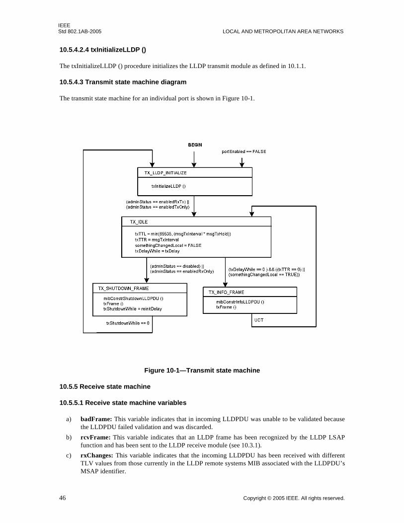
IEEEStd 802.1AB-2005 LOCAL AND METROPOLITAN AREA NETWORKS
10.5.4.2.4 txInitializeLLDP ()
The txInitializeLLDP () procedure initializes the LLDP transmit module as defined in 10.1.1.
10.5.4.3 Transmit state machine diagram
The transmit state machine for an individual port is shown in Figure 10-1.
Figure 10-1—Transmit state machine
10.5.5 Receive state machine
10.5.5.1 Receive state machine variables
a) badFrame: This variable indicates that in incoming LLDPDU was unable to be validated becausethe LLDPDU failed validation and was discarded.
b) rcvFrame: This variable indicates that an LLDP frame has been recognized by the LLDP LSAPfunction and has been sent to the LLDP receive module (see 10.3.1).
c) rxChanges: This variable indicates that the incoming LLDPDU has been received with differentTLV values from those currently in the LLDP remote systems MIB associated with the LLDPDU’sMSAP identifier.
46 Copyright © 2005 IEEE. All rights reserved.
IEEESTATION AND MEDIA ACCESS CONTROL CONNECTIVITY DISCOVERY Std 802.1AB-2005
d) rxInfoAge: This variable indicates that the rxInfoTTL timing counter associated with a particularMSAP identifier in the LLDP remote systems MIB has expired.
e) rxTTL: This variable indicates the time to live value associated with all TLVs received in thecurrent frame.
f) somethingChangedRemote: This per-MSAP variable is only set after all the informationassociated with the particular MSAP identifier has been updated in the LLDP remote systems MIB.The variable serves as an indication to the managers of the PTOPO and other optional MIBs thatindicates one or more of the following, as defined in 10.3.3:
1) That the status/value of one or more objects in the LLDP remote systems MIB associated withthe particular MSAP identifier has changed.
2) That the incoming LLDPDU contains an MSAP identifier requiring creation of a new MIBstructure in the LLDP remote systems MIB to receive the information in the current LLDPDU.
3) That information in the LLDP remote systems MIB associated with the MSAP identifier hasbeen deleted.
g) tooManyNeighbors: This variable indicates that there is insufficient space in the LLDP remotesystems MIB to store information from all connected active remote ports (see 10.3.4).
10.5.5.2 .Receive state machine procedures
10.5.5.2.1 mibDeleteObjects ()
The mibDeleteObjects () procedure deletes all information in the LLDP remote systems MIB associatedwith the MSAP identifier if an LLDPDU is received with an rxTTL value of zero (see 10.3.2) or the timingcounter rxInfoTTL expires. (see 10.3.6).
10.5.5.2.2 mibUpdateObjects ()
The mibUpdateObjects () procedure updates the MIB objects corresponding to the TLVs contained in thereceived LLDPDU for the LLDP remote system indicated by the LLDP remote systems update processdefined in 10.3.5.
NOTE—To avoid a race condition, the flag variable somethingChangedRemote is not set to TRUE until after theinformation in the LLDP remote systems MIB has been updated.
10.5.5.2.3 rxInitializeLLDP ()
The rxInitializeLLDP () procedure initializes the LLDP receive module as defined in 10.1.2.
10.5.5.2.4 rxProcessFrame ()
The rxProcessFrame () procedure:
a) Strips the protocol identification fields from the received frame and validates the TLVs contained inthe LLDPDU as defined in 10.3.1 and 10.3.2.
b) Determines whether or not a MIB update may be required as defined in 10.3.3.
1) If an update is required and sufficient space is available to store the LLDPDU information inthe LLDP remote systems MIB, the control variable rxChanges is set to TRUE.
2) If an update is not required, the control variable rxChanges is set to FALSE.
c) If sufficient space is not available, determines whether to discard the incoming LLDPDU from anew neighbor or to delete information from an existing neighbor that is already in the LLDP remotesystems MIB, as defined in 10.3.4. The tooManyNeighborsTimer and the tooManyNeighbors flagvariable are both set during this process.
Copyright © 2005 IEEE. All rights reserved. 47
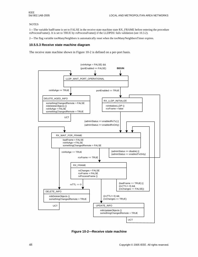
IEEEStd 802.1AB-2005 LOCAL AND METROPOLITAN AREA NETWORKS
NOTES
1—The variable badFrame is set to FALSE in the receive state machine state RX_FRAME before entering the procedurerxProcessFrame(). It is set to TRUE by rxProcessFrame() if the LLDPDU fails validation (see 10.3.2).
2—The flag variable tooManyNeighbors is automatically reset when the tooManyNeighborsTimer expires.
10.5.5.3 Receive state machine diagram
The receive state machine shown in Figure 10-2 is defined on a per-port basis.
Figure 10-2—Receive state machine
RX_WAIT_FOR_FRAME
RX_FRAME
badFrame = FALSErxInfoAge = FALSEsomethingChangedRemote = FALSE
rxChanges = FALSErcvFrame = FALSErxProcessFrame ()
rcvFrame == TRUE
DELETE_INFO
mibDeleteObjects ()somethingChangedRemote = TRUE
rxTTL == 0
rxInfoAge == TRUE
UCT
UCT
(adminStatus == disable) ||(adminStatus == enabledTxOnly)
(badFrame == TRUE) ||((rxTTL!= 0) &&(rxChanges == FALSE))
((rxTTL!= 0) &&(rxChanges == TRUE)
mibUpdateObjects ()somethingChangedRemote = TRUE
UPDATE_INFO
(adminStatus == enabledRxTx) ||
(adminStatus == enabledRxOnly)
RX_LLDP_INITIALIZE
rxInitializeLLDP ()rcvFrame = false
rxInfoAge == TRUE portEnabled == TRUE
(rxInfoAge = FALSE) &&
(portEnabled == FALSE)
LLDP_WAIT_PORT_OPERATIONAL
BEGIN
DELETE_AGED_INFO
somethingChangedRemote = FALSEmibDeleteObjects ()rxInfoAge = FALSEsomethingChangedRemote = TRUE
UCT
48 Copyright © 2005 IEEE. All rights reserved.
IEEESTATION AND MEDIA ACCESS CONTROL CONNECTIVITY DISCOVERY Std 802.1AB-2005
11. LLDP management
This clause defines the set of managed objects and their functionality that allow administrative configurationand monitoring of LLDP operation.
11.1 Data storage and retrieval
LLDP agents need to have a place to store both information about the local system and information theyhave received about remote systems. Data storage and retrieval capability to support the functionalitydefined in Clause 8, Clause 9, Clause 10, and Clause 11 shall be provided. No particular implementation isimplied.
11.2 The LLDP manager’s responsibilities:
The LLDP manager has the following responsibilities:
a) Starting the transmit and receive state machines.
b) Providing a means for the network manager to select TLVs to be included in outgoing LLDPDUs.
c) Extracting the necessary information from the LLDP local system MIB and constructing theindividual TLVs selected for insertion into the LLDPDU.
d) Prepending appropriate addressing and LLDP Ethertype to the LLDPDU before submitting theMA_UNITDATA.request for frame transmission.
e) Updating the LLDP remote systems MIB and monitoring for MIB object adds, deletions, and valuechanges.
f) Maintaining operational statistics.
11.2.1 Protocol initialization management
Protocol initialization consists of:
a) Retrieving non-volatile configuration values for the LLDP local system MIB.
b) Assigning default or management assigned values to LLDP configuration variables.
c) Loading physical topology information into their associated LLDP local system MIB objects.
11.2.2 TLV selection management
TLV selection management consists of providing the network manager with the means to select whichspecific TLVs are enabled for inclusion in an LLDPDU. The following LLDP variables cross reference toLLDP local systems configuration MIB tables indicating which specific TLVs are enabled for the particularport(s) on the system. The specific port(s) through which each TLV is enabled for transmission may be set(or reset) by the network manager:
a) mibBasicTLVsTxEnable: This variable lists the single-instance-use basic management TLVs, eachwith a bit map indicating the system ports through which the referenced TLV is enabled fortransmission.
b) mibMgmtAddrInstanceTxEnable: This variable lists the different management addresses (bysubtype) that are defined for the system, each with a bit map indicating the system ports throughwhich the particular management address/subtype TLV is enabled for transmission.
NOTE—Implementers of new TLVs should be aware that provision needs to be made to allow similar networkmanagement selection of new TLVs and that doing so will require linkage to the LLDP MIB, regardless of whether ornot the TLV is part of the basic management set or part of an Organizationally Specific TLV set.
Copyright © 2005 IEEE. All rights reserved. 49
IEEEStd 802.1AB-2005 LOCAL AND METROPOLITAN AREA NETWORKS
11.2.3 Transmission management
Transmission management consists of:
a) Monitoring both somethingChangedLocal and txTTR to determine when a new transmission cycleis required.
b) Extracting the appropriate LLDP local system MIB information for the three mandatory TLVs andinserting them at the beginning of the LLDPDU in proper format order.
c) Extracting the appropriate LLDP local system MIB information for the selected optional TLVs andinserting them into the LLDPDU.
d) Appending an End Of LLDPDU TLV after the last optional TLV in the LLDPDU.
e) Maintaining length control during LLDPDU construction to ensure that the TLVs do not exceed themaximum length allowed for the LLDPDU.
f) Submitting the frame for transmission.
11.2.4 Reception management
Reception management consists of:
a) Receiving and parsing the incoming LLDPDUs.
b) Validating, and checking the types of the first three TLVs to ensure that they are the required typeand in LLDPDU format order.
c) Validating optional TLVs and extracting information values.
d) Checking whether or not the current LLDPDU represents a new MSAP identifier.
e) Monitoring whether or not there is sufficient space available in the LLDP remote systems MIB forall active neighbors.
f) Arbitrating which information is to be discarded in cases where insufficient space is available in theLLDP remote systems MIB for all active neighbors.
g) Checking whether or not the received information represents a status or value change to the existingMIB object.
h) Updating remote systems MIB objects as necessary.
11.2.5 Performance management
Performance management consists of:
a) Monitoring the LLDP local system MIB update activities for status or value changes to selectedMIB objects and:
1) Setting the variable somethingChangedLocal to TRUE whenever a status/value change occurs.
2) Initiating a new transmit cycle if the txDelayWhile timer has expired.
b) Monitoring the txTTR timer for countdown expiration and initiating a new transmit cycle if thetxDelayWhile timer has expired.
c) Monitoring the rxInfoTTL timer for countdown expiration and:
1) Deleting the associated objects from the LLDP remote systems MIB whenever the timingcounter expires.
2) Setting the variable somethingChangedRemote associated with the MSAP identifier to TRUE.
d) Monitoring rxTTL in the incoming LLDPDUs for shutdown indication and:
1) Deleting the associated objects from the LLDP remote systems MIB whenever rxTTL = 0.
2) Setting the variable somethingChangedRemote associated with the MSAP identifier to TRUE.
50 Copyright © 2005 IEEE. All rights reserved.
IEEESTATION AND MEDIA ACCESS CONTROL CONNECTIVITY DISCOVERY Std 802.1AB-2005
e) Monitoring the “tooManyNeighbors” process to determine whether an existing neighbor’sinformation needs to be deleted and:
1) Deleting the objects associated with a selected MSAP identifier from the LLDP remote systemsMIB whenever existing information is selected to be deleted.
2) Setting the variable somethingChangedRemote associated with the MSAP identifier to TRUE.
f) Monitoring the tooManyNeighborsTimer to determine when there is not sufficient space available toaccommodate information from all active neighbors and setting the variable tooManyNeighborsassociated with the port to FALSE when the tooManyNeighborsTimer expires.
g) Notifying the IETF MIB managers of the optional MIB modules whenever the variablessomethingChangedLocal or somethingChangedRemote become TRUE.
h) Maintaining operational statistics regarding the LLDP frames sent and received.
11.3 Managed objects
Managed objects model the semantics of management operations. Operations upon a managed object supplyinformation concerning, or facilitate control over, the process or entity associated with that managed object.
Management of LLDP is described in terms of the managed resources that are associated with individualTLVs and that support frame transmission and reception.
11.4 Data types
This subclause specifies the semantics of operations independent of their encoding in management protocol.The data types of the parameters of operations are defined for that specification.
The following data types are used:
a) Boolean.
b) Enumerated, for a collection of named values.
c) Unsigned, for all parameters specified as “number of” some quantity.
d) MAC address.
e) Time interval, an Unsigned value representing a positive integral number of seconds for all time outparameters.
f) Counter, for all parameters specified as a “count” of some quantity (all counters increment and wrapwith a modulus of 2 to the power 32).
11.5 LLDP variables
LLDP managed objects fall into the following categories:
a) Status/control variables necessary for operation of the protocol.
b) Variables that accumulate operational statistics.
c) Variables that are required by the particular TLVs.
11.5.1 LLDP operational status and control
a) Global parameters and variables:
1) adminStatus: The authority that controls whether or not a local LLDP agent is enabled fortransmit and receive, transmit only, or receive only; or is disabled (10.5.1).
b) Transmit state machine parameters and variables:
Copyright © 2005 IEEE. All rights reserved. 51
IEEEStd 802.1AB-2005 LOCAL AND METROPOLITAN AREA NETWORKS
1) msgTxHold: A multiplier on msgTxInterval used to compute the TTL value of txTTL(10.5.3.3).
2) msgTxInterval: The interval between successive transmit cycles (10.5.3.3).
3) reinitDelay: The delay after adminStatus becomes ‘disable’ before re-initialization isattempted (10.5.3.3).
4) txDelay: The minimum delay between successive LLDP frame transmissions (10.5.3.3).
c) Receive state machine parameters and variables:
1) somethingChangedRemote: An indication that the status/value of one or more selectedobjects in the LLDP remote systems MIB has changed or that all objects associated with aparticular MSAP identifier have been deleted (10.5.5.1).
2) tooManyNeighbors: An indication that there is insufficient space in the LLDP remote systemsMIB to store information from all active neighbors (10.5.5.1).
11.5.2 LLDP operational statistics counters
The following counters provide operational statistics on a per port basis:
a) Transmission counter:
1) statsFramesOutTotal: A count of all LLDP frames transmitted through the port (10.5.2).
b) Reception counters:
1) statsAgeoutsTotal: A count of the times that a neighbor’s information is deleted from theLLDP remote systems MIB because of rxInfoTTL timer expiration (10.5.2).
2) statsFramesDiscardedTotal: A count of all LLDPDUs received and then discarded (10.5.2).
3) statsFramesInErrorsTotal: A count of all LLDPDUs received at the port with one or moredetectable errors 10.5.2).
4) statsFramesInTotal: A count of all LLDP frames received at the port (10.5.2).
5) statsTlvsDiscardedTotal: A count of all TLVs received at the port and discarded for anyreason (10.5.2).
6) statsTLVsUnrecognizedTotal: This counter provides a count of all TLVs not recognized bythe receiving LLDP local agent (10.5.2).
11.5.3 TLV required variables
Variables in this category are defined by the requirements of the particular TLVs. They are maintained withreference to the local system in the LLDP local system MIB; and with reference to the remote system, in theLLDP remote systems MIB. TLV variables are outputs from the local LLDP agent and inputs to the remoteLLDP agent.
Variables that pertain to basic set TLVs are listed below. Variables pertaining to Organizationally SpecificTLVs are listed in Annex F for IEEE 802.1 defined extensions and in Annex F for IEEE 802.3 definedextensions.
11.5.3.1 Chassis ID TLV objects
a) chassis ID subtype: The type of identifier used for the chassis (see 9.5.2.2).
b) chassis ID: The identification assigned to the chassis containing the port (see 9.5.2.3).
52 Copyright © 2005 IEEE. All rights reserved.
IEEESTATION AND MEDIA ACCESS CONTROL CONNECTIVITY DISCOVERY Std 802.1AB-2005
11.5.3.2 Port ID TLV objects
a) port ID subtype: The type of identifier used for the port (see 9.5.3.2).
b) port ID: The identification assigned to the port (see 9.5.3.3).
11.5.3.3 Port description TLV object
a) port description: The port’s description (see 9.5.5.2).
11.5.3.4 System name TLV object
a) system name: The system’s assigned name (see 9.5.6.2).
11.5.3.5 System description TLV object
a) system description: The system’s description (see 9.5.7.2).
11.5.3.6 System capabilities TLV objects
a) system capabilities: The primary capabilities of the system (see 9.5.8.1).
b) enabled capabilities: The system’s enabled capabilities (see 9.5.8.2).
11.5.3.7 Management address TLV objects
a) management address length: The length of the management address (see 9.5.9.2).
b) management address subtype: The management address type (see 9.5.9.3).
c) management address: The management address (see 9.5.9.4).
d) interface numbering subtype: The interface type (see 9.5.9.5).
e) interface number: The interface number (see 9.5.9.6).
f) OID length: The object identifier length (see 9.5.9.7).
g) OID: The object identifier (see 9.5.9.8).
11.5.4 Relationship between LLDP variables and LLDP managed objects
Table 11-1 lists the relationship both between LLDP operational status/control variables and theircorresponding LLDP CONFIG objects and between LLDP operational statistics variables and theircorresponding LLDP STATS objects.
Copyright © 2005 IEEE. All rights reserved. 53
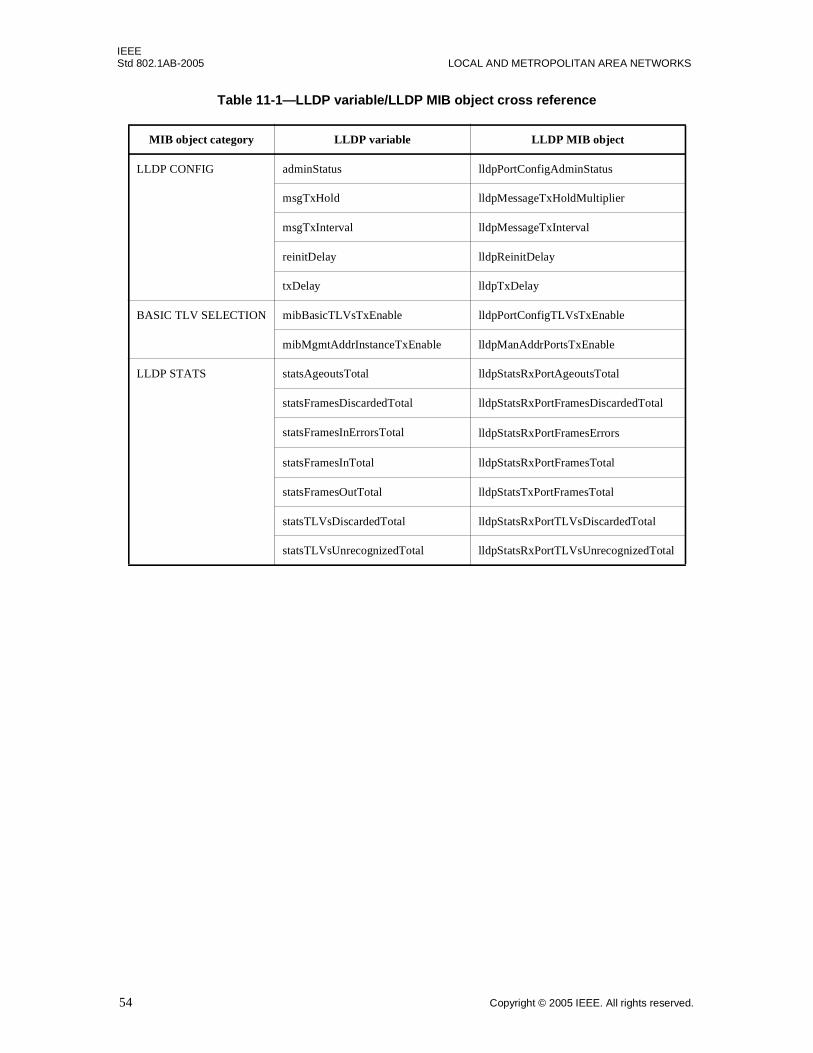
IEEEStd 802.1AB-2005 LOCAL AND METROPOLITAN AREA NETWORKS
Table 11-1—LLDP variable/LLDP MIB object cross reference
MIB object category LLDP variable LLDP MIB object
LLDP CONFIG adminStatus lldpPortConfigAdminStatus
msgTxHold lldpMessageTxHoldMultiplier
msgTxInterval lldpMessageTxInterval
reinitDelay lldpReinitDelay
txDelay lldpTxDelay
BASIC TLV SELECTION mibBasicTLVsTxEnable lldpPortConfigTLVsTxEnable
mibMgmtAddrInstanceTxEnable lldpManAddrPortsTxEnable
LLDP STATS statsAgeoutsTotal lldpStatsRxPortAgeoutsTotal
statsFramesDiscardedTotal lldpStatsRxPortFramesDiscardedTotal
statsFramesInErrorsTotal lldpStatsRxPortFramesErrors
statsFramesInTotal lldpStatsRxPortFramesTotal
statsFramesOutTotal lldpStatsTxPortFramesTotal
statsTLVsDiscardedTotal lldpStatsRxPortTLVsDiscardedTotal
statsTLVsUnrecognizedTotal lldpStatsRxPortTLVsUnrecognizedTotal
54 Copyright © 2005 IEEE. All rights reserved.
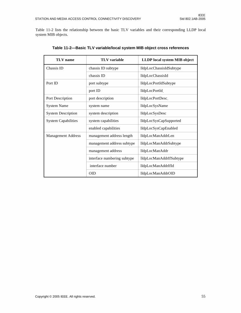
IEEESTATION AND MEDIA ACCESS CONTROL CONNECTIVITY DISCOVERY Std 802.1AB-2005
Table 11-2 lists the relationship between the basic TLV variables and their corresponding LLDP localsystem MIB objects.
Table 11-2—Basic TLV variable/local system MIB object cross references
TLV name TLV variable LLDP local system MIB object
Chassis ID chassis ID subtype lldpLocChassisIdSubtype
chassis ID lldpLocChassisId
Port ID port subtype lldpLocPortIdSubtype
port ID lldpLocPortId
Port Description port description lldpLocPortDesc
System Name system name lldpLocSysName
System Description system description lldpLocSysDesc
System Capabilities system capabilities lldpLocSysCapSupported
enabled capabilities lldpLocSysCapEnabled
Management Address management address length lldpLocManAddrLen
management address subtype lldpLocManAddrSubtype
management address lldpLocManAddr
interface numbering subtype lldpLocManAddrIfSubtype
interface number lldpLocManAddrIfId
OID lldpLocManAddrOID
Copyright © 2005 IEEE. All rights reserved. 55
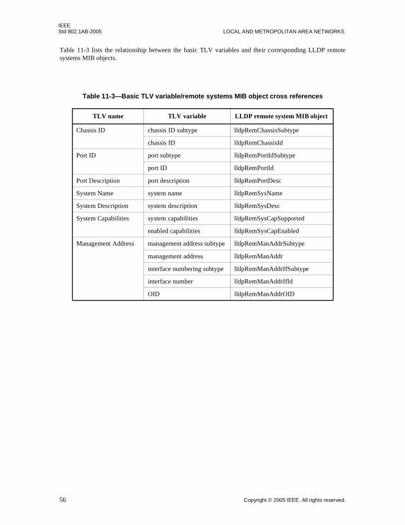
IEEEStd 802.1AB-2005 LOCAL AND METROPOLITAN AREA NETWORKS
Table 11-3 lists the relationship between the basic TLV variables and their corresponding LLDP remotesystems MIB objects.
Table 11-3—Basic TLV variable/remote systems MIB object cross references
TLV name TLV variable LLDP remote system MIB object
Chassis ID chassis ID subtype lldpRemChassisSubtype
chassis ID lldpRemChassisId
Port ID port subtype lldpRemPortIdSubtype
port ID lldpRemPortId
Port Description port description lldpRemPortDesc
System Name system name lldpRemSysName
System Description system description lldpRemSysDesc
System Capabilities system capabilities lldpRemSysCapSupported
enabled capabilities lldpRemSysCapEnabled
Management Address management address subtype lldpRemManAddrSubtype
management address lldpRemManAddr
interface numbering subtype lldpRemManAddrIfSubtype
interface number lldpRemManAddrIfId
OID lldpRemManAddrOID
56 Copyright © 2005 IEEE. All rights reserved.
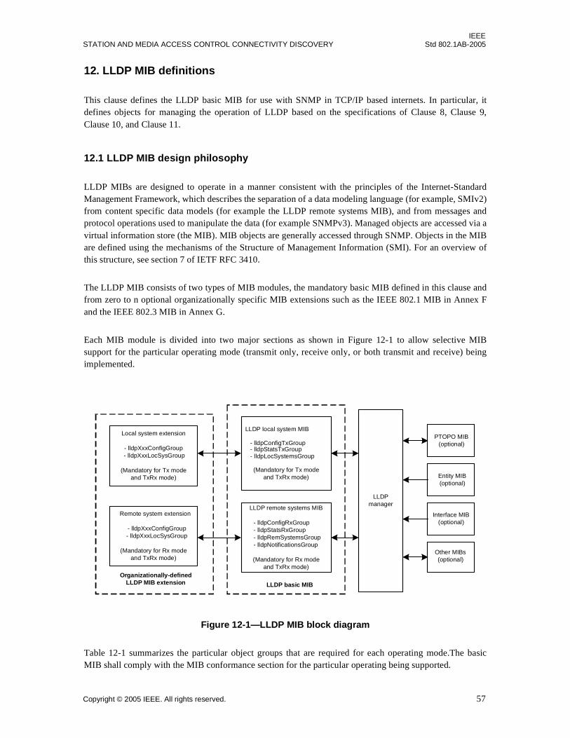
IEEESTATION AND MEDIA ACCESS CONTROL CONNECTIVITY DISCOVERY Std 802.1AB-2005
12. LLDP MIB definitions
This clause defines the LLDP basic MIB for use with SNMP in TCP/IP based internets. In particular, itdefines objects for managing the operation of LLDP based on the specifications of Clause 8, Clause 9,Clause 10, and Clause 11.
12.1 LLDP MIB design philosophy
LLDP MIBs are designed to operate in a manner consistent with the principles of the Internet-StandardManagement Framework, which describes the separation of a data modeling language (for example, SMIv2)from content specific data models (for example the LLDP remote systems MIB), and from messages andprotocol operations used to manipulate the data (for example SNMPv3). Managed objects are accessed via avirtual information store (the MIB). MIB objects are generally accessed through SNMP. Objects in the MIBare defined using the mechanisms of the Structure of Management Information (SMI). For an overview ofthis structure, see section 7 of IETF RFC 3410.
The LLDP MIB consists of two types of MIB modules, the mandatory basic MIB defined in this clause andfrom zero to n optional organizationally specific MIB extensions such as the IEEE 802.1 MIB in Annex Fand the IEEE 802.3 MIB in Annex G.
Each MIB module is divided into two major sections as shown in Figure 12-1 to allow selective MIBsupport for the particular operating mode (transmit only, receive only, or both transmit and receive) beingimplemented.
Figure 12-1—LLDP MIB block diagram
Table 12-1 summarizes the particular object groups that are required for each operating mode.The basicMIB shall comply with the MIB conformance section for the particular operating being supported.
LLDP basic MIB
LLDPmanager
Entity MIB(optional)
Interface MIB(optional)
PTOPO MIB(optional)
Other MIBs(optional)
Organizationally-definedLLDP MIB extension
Local system extension
- lldpXxxConfigGroup - lldpXxxLocSysGroup
(Mandatory for Tx modeand TxRx mode)
Remote system extension
- lldpXxxConfigGroup - lldpXxxLocSysGroup
(Mandatory for Rx modeand TxRx mode)
LLDP local system MIB
- lldpConfigTxGroup - lldpStatsTxGroup - lldpLocSystemsGroup
(Mandatory for Tx modeand TxRx mode)
LLDP remote systems MIB
- lldpConfigRxGroup - lldpStatsRxGroup - lldpRemSystemsGroup - lldpNotificationsGroup
(Mandatory for Rx modeand TxRx mode)
Copyright © 2005 IEEE. All rights reserved. 57

IEEEStd 802.1AB-2005 LOCAL AND METROPOLITAN AREA NETWORKS
12.2 LLDP MIB module 9,10
In the following MIB module, should any discrepancy between the DESCRIPTION text and thecorresponding definition in Clause 10 and Clause 11 occur, the definition in Clause 10 and Clause 11 shalltake precedence.
LLDP-MIB DEFINITIONS ::= BEGIN
IMPORTS MODULE-IDENTITY, OBJECT-TYPE, Integer32, Counter32, NOTIFICATION-TYPE FROM SNMPv2-SMI TEXTUAL-CONVENTION, TimeStamp, TruthValue FROM SNMPv2-TC SnmpAdminString FROM SNMP-FRAMEWORK-MIB MODULE-COMPLIANCE, OBJECT-GROUP, NOTIFICATION-GROUP FROM SNMPv2-CONF TimeFilter, ZeroBasedCounter32 FROM RMON2-MIB AddressFamilyNumbers FROM IANA-ADDRESS-FAMILY-NUMBERS-MIB;
lldpMIB MODULE-IDENTITY LAST-UPDATED "200505060000Z" -- May 06, 2005 ORGANIZATION "IEEE 802.1 Working Group" CONTACT-INFO " WG-URL: http://grouper.ieee.org/groups/802/1/index.html WG-EMail: [email protected]
Contact: Paul Congdon Postal: Hewlett-Packard Company 8000 Foothills Blvd. Roseville, CA 95747 USA
Table 12-1—MIB object group operating mode applicability
MIB group Rx mode Tx mode TxRx mode
lldpConfigRxGroup M* — M
lldpConfigTxGroup — M M
lldpStatsRxGroup M — M
lldpStatsTxGroup — M M
lldpLocSystemsGroup — M M
lldpRemSystemsGroup M — M
lldpNotificationsGroup M — M
*Mandatory
9Copyright release for MIBs: Users of this standard may freely reproduce the MIB contained in this subclause so that it can be used forits intended purpose. 10An ASCII version of this MIB module can be obtained by Web browser from the IEEE 802.1 Website at http://www.ieee802.org/1/pages/MIBS.html.
58 Copyright © 2005 IEEE. All rights reserved.
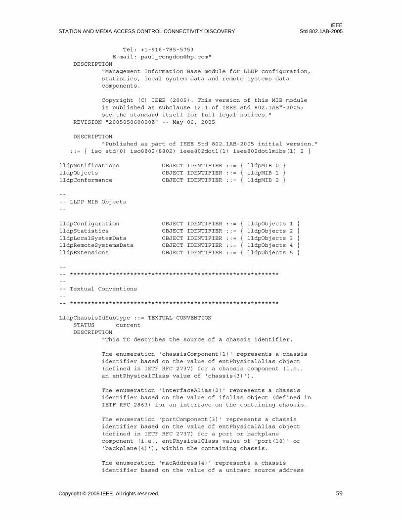
IEEESTATION AND MEDIA ACCESS CONTROL CONNECTIVITY DISCOVERY Std 802.1AB-2005
Tel: +1-916-785-5753 E-mail: [email protected]" DESCRIPTION "Management Information Base module for LLDP configuration, statistics, local system data and remote systems data components.
Copyright (C) IEEE (2005). This version of this MIB module is published as subclause 12.1 of IEEE Std 802.1AB™-2005; see the standard itself for full legal notices." REVISION "200505060000Z" -- May 06, 2005
DESCRIPTION "Published as part of IEEE Std 802.1AB-2005 initial version." ::= { iso std(0) iso8802(8802) ieee802dot1(1) ieee802dot1mibs(1) 2 }
lldpNotifications OBJECT IDENTIFIER ::= { lldpMIB 0 }lldpObjects OBJECT IDENTIFIER ::= { lldpMIB 1 }lldpConformance OBJECT IDENTIFIER ::= { lldpMIB 2 }
---- LLDP MIB Objects--
lldpConfiguration OBJECT IDENTIFIER ::= { lldpObjects 1 }lldpStatistics OBJECT IDENTIFIER ::= { lldpObjects 2 }lldpLocalSystemData OBJECT IDENTIFIER ::= { lldpObjects 3 }lldpRemoteSystemsData OBJECT IDENTIFIER ::= { lldpObjects 4 }lldpExtensions OBJECT IDENTIFIER ::= { lldpObjects 5 }
-- -- ***********************************************************-- -- Textual Conventions-- -- ***********************************************************
LldpChassisIdSubtype ::= TEXTUAL-CONVENTION STATUS current DESCRIPTION "This TC describes the source of a chassis identifier.
The enumeration 'chassisComponent(1)' represents a chassis identifier based on the value of entPhysicalAlias object (defined in IETF RFC 2737) for a chassis component (i.e., an entPhysicalClass value of 'chassis(3)').
The enumeration 'interfaceAlias(2)' represents a chassis identifier based on the value of ifAlias object (defined in IETF RFC 2863) for an interface on the containing chassis.
The enumeration 'portComponent(3)' represents a chassis identifier based on the value of entPhysicalAlias object (defined in IETF RFC 2737) for a port or backplane component (i.e., entPhysicalClass value of 'port(10)' or 'backplane(4)'), within the containing chassis.
The enumeration 'macAddress(4)' represents a chassis identifier based on the value of a unicast source address
Copyright © 2005 IEEE. All rights reserved. 59
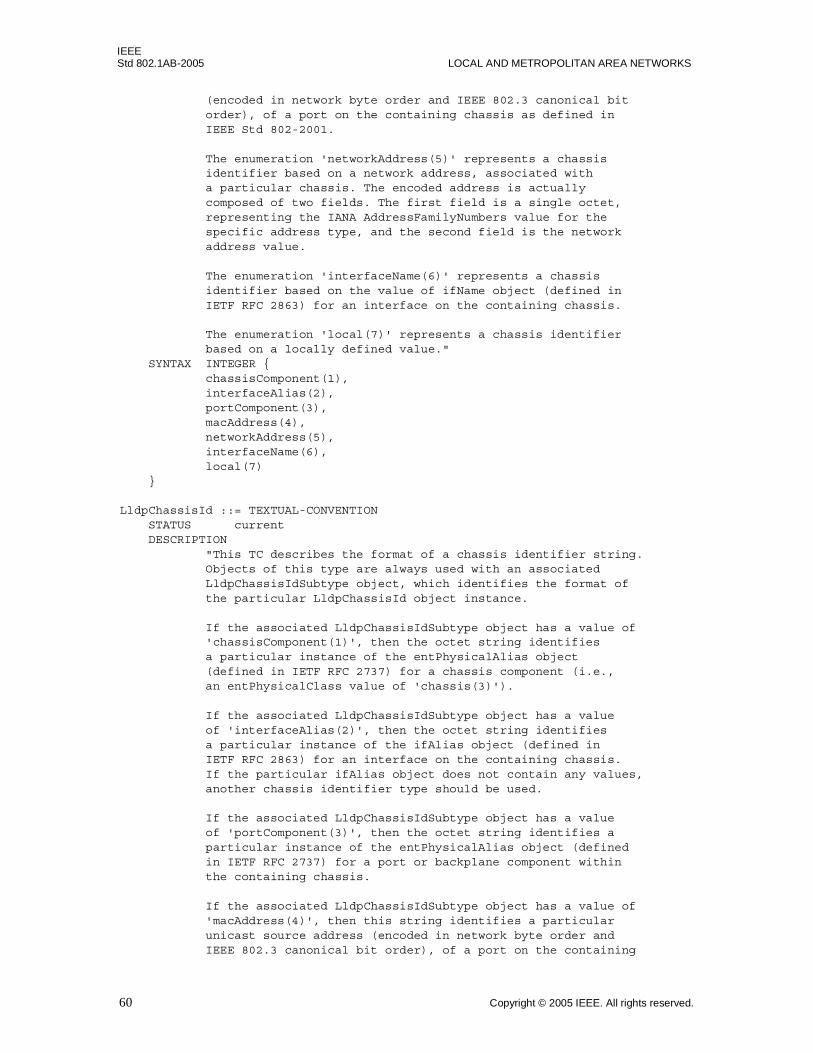
IEEEStd 802.1AB-2005 LOCAL AND METROPOLITAN AREA NETWORKS
(encoded in network byte order and IEEE 802.3 canonical bit order), of a port on the containing chassis as defined in IEEE Std 802-2001.
The enumeration 'networkAddress(5)' represents a chassis identifier based on a network address, associated with a particular chassis. The encoded address is actually composed of two fields. The first field is a single octet, representing the IANA AddressFamilyNumbers value for the specific address type, and the second field is the network address value.
The enumeration 'interfaceName(6)' represents a chassis identifier based on the value of ifName object (defined in IETF RFC 2863) for an interface on the containing chassis.
The enumeration 'local(7)' represents a chassis identifier based on a locally defined value." SYNTAX INTEGER { chassisComponent(1), interfaceAlias(2), portComponent(3), macAddress(4), networkAddress(5), interfaceName(6), local(7) }
LldpChassisId ::= TEXTUAL-CONVENTION STATUS current DESCRIPTION "This TC describes the format of a chassis identifier string. Objects of this type are always used with an associated LldpChassisIdSubtype object, which identifies the format of the particular LldpChassisId object instance.
If the associated LldpChassisIdSubtype object has a value of 'chassisComponent(1)', then the octet string identifies a particular instance of the entPhysicalAlias object (defined in IETF RFC 2737) for a chassis component (i.e., an entPhysicalClass value of 'chassis(3)').
If the associated LldpChassisIdSubtype object has a value of 'interfaceAlias(2)', then the octet string identifies a particular instance of the ifAlias object (defined in IETF RFC 2863) for an interface on the containing chassis. If the particular ifAlias object does not contain any values, another chassis identifier type should be used.
If the associated LldpChassisIdSubtype object has a value of 'portComponent(3)', then the octet string identifies a particular instance of the entPhysicalAlias object (defined in IETF RFC 2737) for a port or backplane component within the containing chassis.
If the associated LldpChassisIdSubtype object has a value of 'macAddress(4)', then this string identifies a particular unicast source address (encoded in network byte order and IEEE 802.3 canonical bit order), of a port on the containing
60 Copyright © 2005 IEEE. All rights reserved.

IEEESTATION AND MEDIA ACCESS CONTROL CONNECTIVITY DISCOVERY Std 802.1AB-2005
chassis as defined in IEEE Std 802-2001.
If the associated LldpChassisIdSubtype object has a value of 'networkAddress(5)', then this string identifies a particular network address, encoded in network byte order, associated with one or more ports on the containing chassis. The first octet contains the IANA Address Family Numbers enumeration value for the specific address type, and octets 2 through N contain the network address value in network byte order.
If the associated LldpChassisIdSubtype object has a value of 'interfaceName(6)', then the octet string identifies a particular instance of the ifName object (defined in IETF RFC 2863) for an interface on the containing chassis. If the particular ifName object does not contain any values, another chassis identifier type should be used.
If the associated LldpChassisIdSubtype object has a value of 'local(7)', then this string identifies a locally assigned Chassis ID." SYNTAX OCTET STRING (SIZE (1..255))
LldpPortIdSubtype ::= TEXTUAL-CONVENTION STATUS current DESCRIPTION "This TC describes the source of a particular type of port identifier used in the LLDP MIB.
The enumeration 'interfaceAlias(1)' represents a port identifier based on the ifAlias MIB object, defined in IETF RFC 2863.
The enumeration 'portComponent(2)' represents a port identifier based on the value of entPhysicalAlias (defined in IETF RFC 2737) for a port component (i.e., entPhysicalClass value of 'port(10)'), within the containing chassis.
The enumeration 'macAddress(3)' represents a port identifier based on a unicast source address (encoded in network byte order and IEEE 802.3 canonical bit order), which has been detected by the agent and associated with a particular port (IEEE Std 802-2001).
The enumeration 'networkAddress(4)' represents a port identifier based on a network address, detected by the agent and associated with a particular port.
The enumeration 'interfaceName(5)' represents a port identifier based on the ifName MIB object, defined in IETF RFC 2863.
The enumeration 'agentCircuitId(6)' represents a port identifier based on the agent-local identifier of the circuit (defined in RFC 3046), detected by the agent and associated with a particular port.
The enumeration 'local(7)' represents a port identifier based on a value locally assigned."
Copyright © 2005 IEEE. All rights reserved. 61
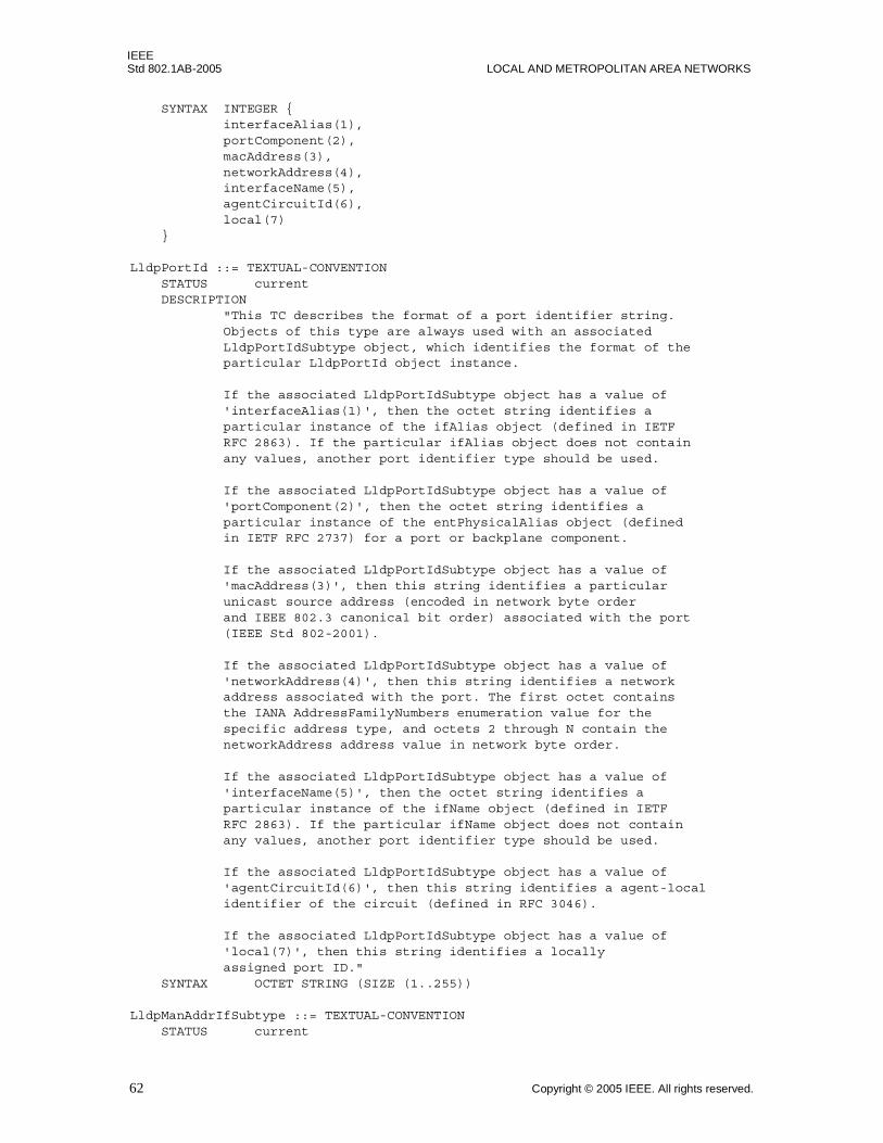
IEEEStd 802.1AB-2005 LOCAL AND METROPOLITAN AREA NETWORKS
SYNTAX INTEGER { interfaceAlias(1), portComponent(2), macAddress(3), networkAddress(4), interfaceName(5), agentCircuitId(6), local(7) }
LldpPortId ::= TEXTUAL-CONVENTION STATUS current DESCRIPTION "This TC describes the format of a port identifier string. Objects of this type are always used with an associated LldpPortIdSubtype object, which identifies the format of the particular LldpPortId object instance.
If the associated LldpPortIdSubtype object has a value of 'interfaceAlias(1)', then the octet string identifies a particular instance of the ifAlias object (defined in IETF RFC 2863). If the particular ifAlias object does not contain any values, another port identifier type should be used.
If the associated LldpPortIdSubtype object has a value of 'portComponent(2)', then the octet string identifies a particular instance of the entPhysicalAlias object (defined in IETF RFC 2737) for a port or backplane component.
If the associated LldpPortIdSubtype object has a value of 'macAddress(3)', then this string identifies a particular unicast source address (encoded in network byte order and IEEE 802.3 canonical bit order) associated with the port (IEEE Std 802-2001).
If the associated LldpPortIdSubtype object has a value of 'networkAddress(4)', then this string identifies a network address associated with the port. The first octet contains the IANA AddressFamilyNumbers enumeration value for the specific address type, and octets 2 through N contain the networkAddress address value in network byte order.
If the associated LldpPortIdSubtype object has a value of 'interfaceName(5)', then the octet string identifies a particular instance of the ifName object (defined in IETF RFC 2863). If the particular ifName object does not contain any values, another port identifier type should be used.
If the associated LldpPortIdSubtype object has a value of 'agentCircuitId(6)', then this string identifies a agent-local identifier of the circuit (defined in RFC 3046).
If the associated LldpPortIdSubtype object has a value of 'local(7)', then this string identifies a locally assigned port ID." SYNTAX OCTET STRING (SIZE (1..255))
LldpManAddrIfSubtype ::= TEXTUAL-CONVENTION STATUS current
62 Copyright © 2005 IEEE. All rights reserved.
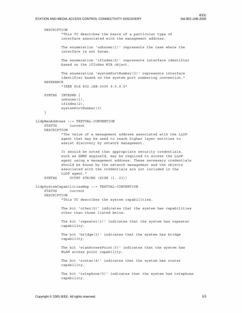
IEEESTATION AND MEDIA ACCESS CONTROL CONNECTIVITY DISCOVERY Std 802.1AB-2005
DESCRIPTION "This TC describes the basis of a particular type of interface associated with the management address.
The enumeration 'unknown(1)' represents the case where the interface is not known.
The enumeration 'ifIndex(2)' represents interface identifier based on the ifIndex MIB object.
The enumeration 'systemPortNumber(3)' represents interface identifier based on the system port numbering convention." REFERENCE "IEEE Std 802.1AB-2005 9.5.9.5" SYNTAX INTEGER { unknown(1), ifIndex(2), systemPortNumber(3) }
LldpManAddress ::= TEXTUAL-CONVENTION STATUS current DESCRIPTION "The value of a management address associated with the LLDP agent that may be used to reach higher layer entities to assist discovery by network management.
It should be noted that appropriate security credentials, such as SNMP engineId, may be required to access the LLDP agent using a management address. These necessary credentials should be known by the network management and the objects associated with the credentials are not included in the LLDP agent." SYNTAX OCTET STRING (SIZE (1..31))
LldpSystemCapabilitiesMap ::= TEXTUAL-CONVENTION STATUS current DESCRIPTION "This TC describes the system capabilities.
The bit 'other(0)' indicates that the system has capabilities other than those listed below.
The bit 'repeater(1)' indicates that the system has repeater capability.
The bit 'bridge(2)' indicates that the system has bridge capability.
The bit 'wlanAccessPoint(3)' indicates that the system has WLAN access point capability.
The bit 'router(4)' indicates that the system has router capability.
The bit 'telephone(5)' indicates that the system has telephone capability.
Copyright © 2005 IEEE. All rights reserved. 63

IEEEStd 802.1AB-2005 LOCAL AND METROPOLITAN AREA NETWORKS
The bit 'docsisCableDevice(6)' indicates that the system has DOCSIS Cable Device capability (IETF RFC 2669 & 2670).
The bit 'stationOnly(7)' indicates that the system has only station capability and nothing else." SYNTAX BITS { other(0), repeater(1), bridge(2), wlanAccessPoint(3), router(4), telephone(5), docsisCableDevice(6), stationOnly(7) }
LldpPortNumber ::= TEXTUAL-CONVENTION DISPLAY-HINT "d" STATUS current DESCRIPTION "Each port contained in the chassis (that is known to the LLDP agent) is uniquely identified by a port number.
A port number has no mandatory relationship to an InterfaceIndex object (of the interfaces MIB, IETF RFC 2863). If the LLDP agent is a IEEE 802.1D, IEEE 802.1Q bridge, the LldpPortNumber will have the same value as the dot1dBasePort object (defined in IETF RFC 1493) associated corresponding bridge port. If the system hosting LLDP agent is not an IEEE 802.1D or an IEEE 802.1Q bridge, the LldpPortNumber will have the same value as the corresponding interface's InterfaceIndex object.
Port numbers should be in the range of 1 and 4096 since a particular port is also represented by the corresponding port number bit in LldpPortList." SYNTAX Integer32(1..4096)
LldpPortList ::= TEXTUAL-CONVENTION STATUS current DESCRIPTION "Each octet within this value specifies a set of eight ports, with the first octet specifying ports 1 through 8, the second octet specifying ports 9 through 16, etc. Within each octet, the most significant bit represents the lowest numbered port, and the least significant bit represents the highest numbered port. Thus, each port of the system is represented by a single bit within the value of this object. If that bit has a value of '1' then that port is included in the set of ports; the port is not included if its bit has a value of '0'." REFERENCE "IETF RFC 2674 section 5" SYNTAX OCTET STRING(SIZE(0..512))
-- -- ***********************************************************-- -- L L D P C O N F I G --
64 Copyright © 2005 IEEE. All rights reserved.

IEEESTATION AND MEDIA ACCESS CONTROL CONNECTIVITY DISCOVERY Std 802.1AB-2005
-- *********************************************************** --
lldpMessageTxInterval OBJECT-TYPE SYNTAX Integer32(5..32768) UNITS "seconds" MAX-ACCESS read-write STATUS current DESCRIPTION "The interval at which LLDP frames are transmitted on behalf of this LLDP agent.
The default value for lldpMessageTxInterval object is 30 seconds.
The value of this object must be restored from non-volatile storage after a re-initialization of the management system." REFERENCE "IEEE Std 802.1AB-2005 10.5.3.3" DEFVAL { 30 } ::= { lldpConfiguration 1 }
lldpMessageTxHoldMultiplier OBJECT-TYPE SYNTAX Integer32(2..10) MAX-ACCESS read-write STATUS current DESCRIPTION "The time-to-live value expressed as a multiple of the lldpMessageTxInterval object. The actual time-to-live value used in LLDP frames, transmitted on behalf of this LLDP agent, can be expressed by the following formula: TTL = min(65535, (lldpMessageTxInterval * lldpMessageTxHoldMultiplier)) For example, if the value of lldpMessageTxInterval is '30', and the value of lldpMessageTxHoldMultiplier is '4', then the value '120' is encoded in the TTL field in the LLDP header.
The default value for lldpMessageTxHoldMultiplier object is 4.
The value of this object must be restored from non-volatile storage after a re-initialization of the management system." REFERENCE "IEEE Std 802.1AB-2005 10.5.3.3" DEFVAL { 4 } ::= { lldpConfiguration 2 }
lldpReinitDelay OBJECT-TYPE SYNTAX Integer32(1..10) UNITS "seconds" MAX-ACCESS read-write STATUS current DESCRIPTION "The lldpReinitDelay indicates the delay (in units of seconds) from when lldpPortConfigAdminStatus object of a particular port becomes 'disabled' until re-initialization will be attempted.
The default value for lldpReintDelay object is two seconds.
The value of this object must be restored from non-volatile
Copyright © 2005 IEEE. All rights reserved. 65

IEEEStd 802.1AB-2005 LOCAL AND METROPOLITAN AREA NETWORKS
storage after a re-initialization of the management system." REFERENCE "IEEE Std 802.1AB-2005 10.5.3.3" DEFVAL { 2 } ::= { lldpConfiguration 3 }
lldpTxDelay OBJECT-TYPE SYNTAX Integer32(1..8192) UNITS "seconds" MAX-ACCESS read-write STATUS current DESCRIPTION "The lldpTxDelay indicates the delay (in units of seconds) between successive LLDP frame transmissions initiated by value/status changes in the LLDP local systems MIB. The recommended value for the lldpTxDelay is set by the following formula:
1 <= lldpTxDelay <= (0.25 * lldpMessageTxInterval)
The default value for lldpTxDelay object is two seconds.
The value of this object must be restored from non-volatile storage after a re-initialization of the management system." REFERENCE "IEEE Std 802.1AB-2005 10.5.3.3" DEFVAL { 2 } ::= { lldpConfiguration 4 }
lldpNotificationInterval OBJECT-TYPE SYNTAX Integer32(5..3600) UNITS "seconds" MAX-ACCESS read-write STATUS current DESCRIPTION "This object controls the transmission of LLDP notifications.
the agent must not generate more than one lldpRemTablesChange notification-event in the indicated period, where a 'notification-event' is the transmission of a single notification PDU type to a list of notification destinations. If additional changes in lldpRemoteSystemsData object groups occur within the indicated throttling period, then these trap- events must be suppressed by the agent. An NMS should periodically check the value of lldpStatsRemTableLastChangeTime to detect any missed lldpRemTablesChange notification-events, e.g. due to throttling or transmission loss.
If notification transmission is enabled for particular ports, the suggested default throttling period is 5 seconds.
The value of this object must be restored from non-volatile storage after a re-initialization of the management system." DEFVAL { 5 } ::= { lldpConfiguration 5 }
---- lldpPortConfigTable: LLDP configuration on a per port basis
66 Copyright © 2005 IEEE. All rights reserved.
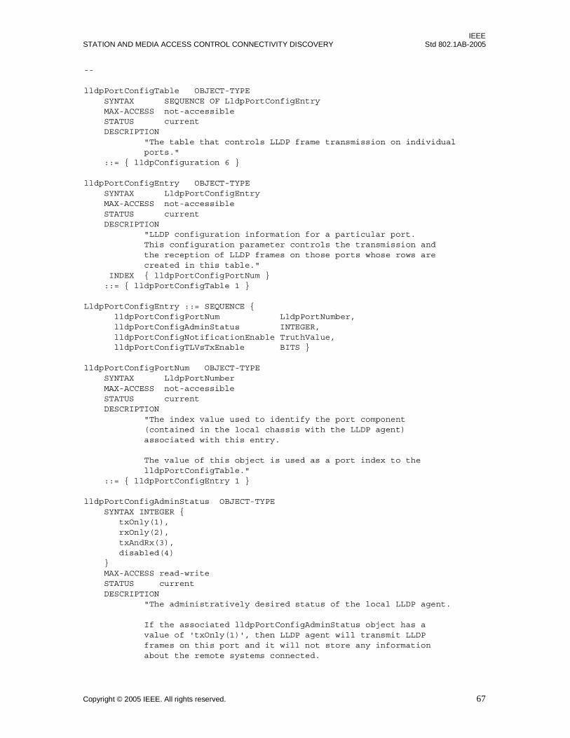
IEEESTATION AND MEDIA ACCESS CONTROL CONNECTIVITY DISCOVERY Std 802.1AB-2005
--
lldpPortConfigTable OBJECT-TYPE SYNTAX SEQUENCE OF LldpPortConfigEntry MAX-ACCESS not-accessible STATUS current DESCRIPTION "The table that controls LLDP frame transmission on individual ports." ::= { lldpConfiguration 6 }
lldpPortConfigEntry OBJECT-TYPE SYNTAX LldpPortConfigEntry MAX-ACCESS not-accessible STATUS current DESCRIPTION "LLDP configuration information for a particular port. This configuration parameter controls the transmission and the reception of LLDP frames on those ports whose rows are created in this table." INDEX { lldpPortConfigPortNum } ::= { lldpPortConfigTable 1 }
LldpPortConfigEntry ::= SEQUENCE { lldpPortConfigPortNum LldpPortNumber, lldpPortConfigAdminStatus INTEGER, lldpPortConfigNotificationEnable TruthValue, lldpPortConfigTLVsTxEnable BITS }
lldpPortConfigPortNum OBJECT-TYPE SYNTAX LldpPortNumber MAX-ACCESS not-accessible STATUS current DESCRIPTION "The index value used to identify the port component (contained in the local chassis with the LLDP agent) associated with this entry.
The value of this object is used as a port index to the lldpPortConfigTable." ::= { lldpPortConfigEntry 1 }
lldpPortConfigAdminStatus OBJECT-TYPE SYNTAX INTEGER { txOnly(1), rxOnly(2), txAndRx(3), disabled(4) } MAX-ACCESS read-write STATUS current DESCRIPTION "The administratively desired status of the local LLDP agent.
If the associated lldpPortConfigAdminStatus object has a value of 'txOnly(1)', then LLDP agent will transmit LLDP frames on this port and it will not store any information about the remote systems connected.
Copyright © 2005 IEEE. All rights reserved. 67
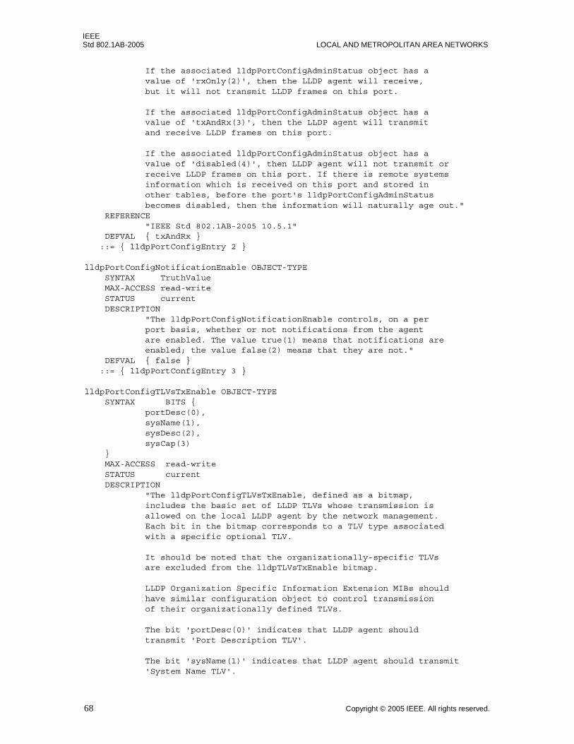
IEEEStd 802.1AB-2005 LOCAL AND METROPOLITAN AREA NETWORKS
If the associated lldpPortConfigAdminStatus object has a value of 'rxOnly(2)', then the LLDP agent will receive, but it will not transmit LLDP frames on this port.
If the associated lldpPortConfigAdminStatus object has a value of 'txAndRx(3)', then the LLDP agent will transmit and receive LLDP frames on this port.
If the associated lldpPortConfigAdminStatus object has a value of 'disabled(4)', then LLDP agent will not transmit or receive LLDP frames on this port. If there is remote systems information which is received on this port and stored in other tables, before the port's lldpPortConfigAdminStatus becomes disabled, then the information will naturally age out." REFERENCE "IEEE Std 802.1AB-2005 10.5.1" DEFVAL { txAndRx } ::= { lldpPortConfigEntry 2 }
lldpPortConfigNotificationEnable OBJECT-TYPE SYNTAX TruthValue MAX-ACCESS read-write STATUS current DESCRIPTION "The lldpPortConfigNotificationEnable controls, on a per port basis, whether or not notifications from the agent are enabled. The value true(1) means that notifications are enabled; the value false(2) means that they are not." DEFVAL { false } ::= { lldpPortConfigEntry 3 }
lldpPortConfigTLVsTxEnable OBJECT-TYPE SYNTAX BITS { portDesc(0), sysName(1), sysDesc(2), sysCap(3) } MAX-ACCESS read-write STATUS current DESCRIPTION "The lldpPortConfigTLVsTxEnable, defined as a bitmap, includes the basic set of LLDP TLVs whose transmission is allowed on the local LLDP agent by the network management. Each bit in the bitmap corresponds to a TLV type associated with a specific optional TLV.
It should be noted that the organizationally-specific TLVs are excluded from the lldpTLVsTxEnable bitmap. LLDP Organization Specific Information Extension MIBs should have similar configuration object to control transmission of their organizationally defined TLVs.
The bit 'portDesc(0)' indicates that LLDP agent should transmit 'Port Description TLV'.
The bit 'sysName(1)' indicates that LLDP agent should transmit 'System Name TLV'.
68 Copyright © 2005 IEEE. All rights reserved.

IEEESTATION AND MEDIA ACCESS CONTROL CONNECTIVITY DISCOVERY Std 802.1AB-2005
The bit 'sysDesc(2)' indicates that LLDP agent should transmit 'System Description TLV'.
The bit 'sysCap(3)' indicates that LLDP agent should transmit 'System Capabilities TLV'.
There is no bit reserved for the management address TLV type since transmission of management address TLVs are controlled by another object, lldpConfigManAddrTable.
The default value for lldpPortConfigTLVsTxEnable object is empty set, which means no enumerated values are set.
The value of this object must be restored from non-volatile storage after a re-initialization of the management system." REFERENCE "IEEE Std 802.1AB-2005 10.2.1.1" DEFVAL { { } } ::= { lldpPortConfigEntry 4 }
---- lldpManAddrConfigTxPortsTable : selection of management addresses-- to be transmitted on a specified set-- of ports.--
lldpConfigManAddrTable OBJECT-TYPE SYNTAX SEQUENCE OF LldpConfigManAddrEntry MAX-ACCESS not-accessible STATUS current DESCRIPTION "The table that controls selection of LLDP management address TLV instances to be transmitted on individual ports." ::= { lldpConfiguration 7 }
lldpConfigManAddrEntry OBJECT-TYPE SYNTAX LldpConfigManAddrEntry MAX-ACCESS not-accessible STATUS current DESCRIPTION "LLDP configuration information that specifies the set of ports (represented as a PortList) on which the local system management address instance will be transmitted.
This configuration object augments the lldpLocManAddrEntry, therefore it is only present along with the management address instance contained in the associated lldpLocManAddrEntry entry.
Each active lldpConfigManAddrEntry must be restored from non-volatile and re-created (along with the corresponding lldpLocManAddrEntry) after a re-initialization of the management system." AUGMENTS { lldpLocManAddrEntry } ::= { lldpConfigManAddrTable 1 }
LldpConfigManAddrEntry ::= SEQUENCE { lldpConfigManAddrPortsTxEnable LldpPortList
Copyright © 2005 IEEE. All rights reserved. 69

IEEEStd 802.1AB-2005 LOCAL AND METROPOLITAN AREA NETWORKS
}
lldpConfigManAddrPortsTxEnable OBJECT-TYPE SYNTAX LldpPortList MAX-ACCESS read-write STATUS current DESCRIPTION "A set of ports that are identified by a PortList, in which each port is represented as a bit. The corresponding local system management address instance will be transmitted on the member ports of the lldpManAddrPortsTxEnable.
The default value for lldpConfigManAddrPortsTxEnable object is empty binary string, which means no ports are specified for advertising indicated management address instance." REFERENCE "IEEE Std 802.1AB-2005 10.2.1.1" DEFVAL { ''H } -- empty binary string ::= { lldpConfigManAddrEntry 1 }
---- *********************************************************** ---- L L D P S T A T S ---- *********************************************************** ---- LLDP Stats Group
lldpStatsRemTablesLastChangeTime OBJECT-TYPE SYNTAX TimeStamp MAX-ACCESS read-only STATUS current DESCRIPTION "The value of sysUpTime object (defined in IETF RFC 3418) at the time an entry is created, modified, or deleted in the in tables associated with the lldpRemoteSystemsData objects and all LLDP extension objects associated with remote systems.
An NMS can use this object to reduce polling of the lldpRemoteSystemsData objects." ::= { lldpStatistics 1 }
lldpStatsRemTablesInserts OBJECT-TYPE SYNTAX ZeroBasedCounter32 UNITS "table entries" MAX-ACCESS read-only STATUS current DESCRIPTION "The number of times the complete set of information advertised by a particular MSAP has been inserted into tables contained in lldpRemoteSystemsData and lldpExtensions objects.
The complete set of information received from a particular MSAP should be inserted into related tables. If partial information cannot be inserted for a reason such as lack of resources, all of the complete set of information should be removed.
70 Copyright © 2005 IEEE. All rights reserved.
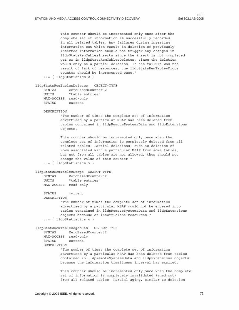
IEEESTATION AND MEDIA ACCESS CONTROL CONNECTIVITY DISCOVERY Std 802.1AB-2005
This counter should be incremented only once after the complete set of information is successfully recorded in all related tables. Any failures during inserting information set which result in deletion of previously inserted information should not trigger any changes in lldpStatsRemTablesInserts since the insert is not completed yet or in lldpStatsRemTablesDeletes, since the deletion would only be a partial deletion. If the failure was the result of lack of resources, the lldpStatsRemTablesDrops counter should be incremented once." ::= { lldpStatistics 2 }
lldpStatsRemTablesDeletes OBJECT-TYPE SYNTAX ZeroBasedCounter32 UNITS "table entries" MAX-ACCESS read-only STATUS current
DESCRIPTION "The number of times the complete set of information advertised by a particular MSAP has been deleted from tables contained in lldpRemoteSystemsData and lldpExtensions objects.
This counter should be incremented only once when the complete set of information is completely deleted from all related tables. Partial deletions, such as deletion of rows associated with a particular MSAP from some tables, but not from all tables are not allowed, thus should not change the value of this counter." ::= { lldpStatistics 3 }
lldpStatsRemTablesDrops OBJECT-TYPE SYNTAX ZeroBasedCounter32 UNITS "table entries" MAX-ACCESS read-only
STATUS current DESCRIPTION "The number of times the complete set of information advertised by a particular MSAP could not be entered into tables contained in lldpRemoteSystemsData and lldpExtensions objects because of insufficient resources." ::= { lldpStatistics 4 }
lldpStatsRemTablesAgeouts OBJECT-TYPE SYNTAX ZeroBasedCounter32 MAX-ACCESS read-only STATUS current DESCRIPTION "The number of times the complete set of information advertised by a particular MSAP has been deleted from tables contained in lldpRemoteSystemsData and lldpExtensions objects because the information timeliness interval has expired.
This counter should be incremented only once when the complete set of information is completely invalidated (aged out) from all related tables. Partial aging, similar to deletion
Copyright © 2005 IEEE. All rights reserved. 71
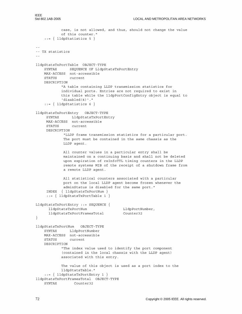
IEEEStd 802.1AB-2005 LOCAL AND METROPOLITAN AREA NETWORKS
case, is not allowed, and thus, should not change the value of this counter." ::= { lldpStatistics 5 }
---- TX statistics--
lldpStatsTxPortTable OBJECT-TYPE SYNTAX SEQUENCE OF LldpStatsTxPortEntry MAX-ACCESS not-accessible STATUS current DESCRIPTION "A table containing LLDP transmission statistics for individual ports. Entries are not required to exist in this table while the lldpPortConfigEntry object is equal to 'disabled(4)'." ::= { lldpStatistics 6 }
lldpStatsTxPortEntry OBJECT-TYPE SYNTAX LldpStatsTxPortEntry MAX-ACCESS not-accessible STATUS current DESCRIPTION "LLDP frame transmission statistics for a particular port. The port must be contained in the same chassis as the LLDP agent. All counter values in a particular entry shall be maintained on a continuing basis and shall not be deleted upon expiration of rxInfoTTL timing counters in the LLDP remote systems MIB of the receipt of a shutdown frame from a remote LLDP agent.
All statistical counters associated with a particular port on the local LLDP agent become frozen whenever the adminStatus is disabled for the same port." INDEX { lldpStatsTxPortNum } ::= { lldpStatsTxPortTable 1 }
LldpStatsTxPortEntry ::= SEQUENCE { lldpStatsTxPortNum LldpPortNumber, lldpStatsTxPortFramesTotal Counter32}
lldpStatsTxPortNum OBJECT-TYPE SYNTAX LldpPortNumber MAX-ACCESS not-accessible STATUS current DESCRIPTION "The index value used to identify the port component (contained in the local chassis with the LLDP agent) associated with this entry.
The value of this object is used as a port index to the lldpStatsTable." ::= { lldpStatsTxPortEntry 1 } lldpStatsTxPortFramesTotal OBJECT-TYPE SYNTAX Counter32
72 Copyright © 2005 IEEE. All rights reserved.
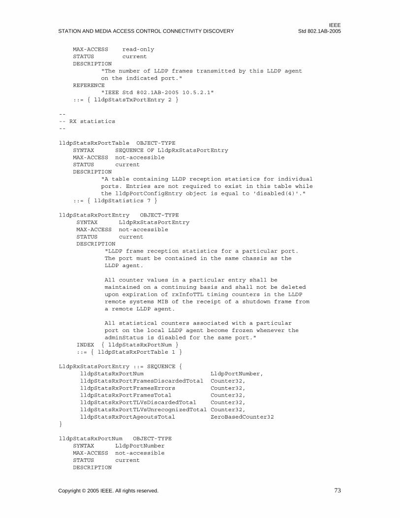
IEEESTATION AND MEDIA ACCESS CONTROL CONNECTIVITY DISCOVERY Std 802.1AB-2005
MAX-ACCESS read-only STATUS current DESCRIPTION "The number of LLDP frames transmitted by this LLDP agent on the indicated port." REFERENCE "IEEE Std 802.1AB-2005 10.5.2.1" ::= { lldpStatsTxPortEntry 2 }
---- RX statistics--
lldpStatsRxPortTable OBJECT-TYPE SYNTAX SEQUENCE OF LldpRxStatsPortEntry MAX-ACCESS not-accessible STATUS current DESCRIPTION "A table containing LLDP reception statistics for individual ports. Entries are not required to exist in this table while the lldpPortConfigEntry object is equal to 'disabled(4)'." ::= { lldpStatistics 7 }
lldpStatsRxPortEntry OBJECT-TYPE SYNTAX LldpRxStatsPortEntry MAX-ACCESS not-accessible STATUS current DESCRIPTION "LLDP frame reception statistics for a particular port. The port must be contained in the same chassis as the LLDP agent. All counter values in a particular entry shall be maintained on a continuing basis and shall not be deleted upon expiration of rxInfoTTL timing counters in the LLDP remote systems MIB of the receipt of a shutdown frame from a remote LLDP agent.
All statistical counters associated with a particular port on the local LLDP agent become frozen whenever the adminStatus is disabled for the same port." INDEX { lldpStatsRxPortNum } ::= { lldpStatsRxPortTable 1 }
LldpRxStatsPortEntry ::= SEQUENCE { lldpStatsRxPortNum LldpPortNumber, lldpStatsRxPortFramesDiscardedTotal Counter32, lldpStatsRxPortFramesErrors Counter32, lldpStatsRxPortFramesTotal Counter32, lldpStatsRxPortTLVsDiscardedTotal Counter32, lldpStatsRxPortTLVsUnrecognizedTotal Counter32, lldpStatsRxPortAgeoutsTotal ZeroBasedCounter32}
lldpStatsRxPortNum OBJECT-TYPE SYNTAX LldpPortNumber MAX-ACCESS not-accessible STATUS current DESCRIPTION
Copyright © 2005 IEEE. All rights reserved. 73
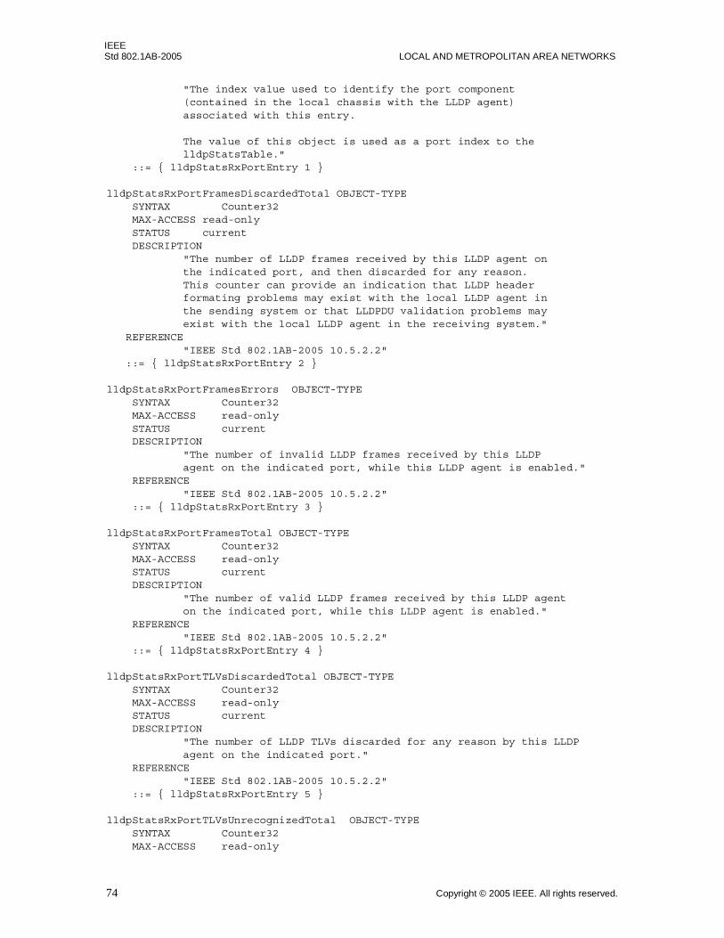
IEEEStd 802.1AB-2005 LOCAL AND METROPOLITAN AREA NETWORKS
"The index value used to identify the port component (contained in the local chassis with the LLDP agent) associated with this entry.
The value of this object is used as a port index to the lldpStatsTable." ::= { lldpStatsRxPortEntry 1 }
lldpStatsRxPortFramesDiscardedTotal OBJECT-TYPE SYNTAX Counter32 MAX-ACCESS read-only STATUS current DESCRIPTION "The number of LLDP frames received by this LLDP agent on the indicated port, and then discarded for any reason. This counter can provide an indication that LLDP header formating problems may exist with the local LLDP agent in the sending system or that LLDPDU validation problems may exist with the local LLDP agent in the receiving system." REFERENCE "IEEE Std 802.1AB-2005 10.5.2.2" ::= { lldpStatsRxPortEntry 2 }
lldpStatsRxPortFramesErrors OBJECT-TYPE SYNTAX Counter32 MAX-ACCESS read-only STATUS current DESCRIPTION "The number of invalid LLDP frames received by this LLDP agent on the indicated port, while this LLDP agent is enabled." REFERENCE "IEEE Std 802.1AB-2005 10.5.2.2" ::= { lldpStatsRxPortEntry 3 }
lldpStatsRxPortFramesTotal OBJECT-TYPE SYNTAX Counter32 MAX-ACCESS read-only STATUS current DESCRIPTION "The number of valid LLDP frames received by this LLDP agent on the indicated port, while this LLDP agent is enabled." REFERENCE "IEEE Std 802.1AB-2005 10.5.2.2" ::= { lldpStatsRxPortEntry 4 }
lldpStatsRxPortTLVsDiscardedTotal OBJECT-TYPE SYNTAX Counter32 MAX-ACCESS read-only STATUS current DESCRIPTION "The number of LLDP TLVs discarded for any reason by this LLDP agent on the indicated port." REFERENCE "IEEE Std 802.1AB-2005 10.5.2.2" ::= { lldpStatsRxPortEntry 5 }
lldpStatsRxPortTLVsUnrecognizedTotal OBJECT-TYPE SYNTAX Counter32 MAX-ACCESS read-only
74 Copyright © 2005 IEEE. All rights reserved.

IEEESTATION AND MEDIA ACCESS CONTROL CONNECTIVITY DISCOVERY Std 802.1AB-2005
STATUS current DESCRIPTION "The number of LLDP TLVs received on the given port that are not recognized by this LLDP agent on the indicated port. An unrecognized TLV is referred to as the TLV whose type value is in the range of reserved TLV types (000 1001 - 111 1110) in Table 9.1 of IEEE Std 802.1AB-2005. An unrecognized TLV may be a basic management TLV from a later LLDP version." REFERENCE "IEEE Std 802.1AB-2005 10.5.2.2" ::= { lldpStatsRxPortEntry 6 }
lldpStatsRxPortAgeoutsTotal OBJECT-TYPE SYNTAX ZeroBasedCounter32 MAX-ACCESS read-only STATUS current DESCRIPTION "The counter that represents the number of age-outs that occurred on a given port. An age-out is the number of times the complete set of information advertised by a particular MSAP has been deleted from tables contained in lldpRemoteSystemsData and lldpExtensions objects because the information timeliness interval has expired.
This counter is similar to lldpStatsRemTablesAgeouts, except that the counter is on a per port basis. This enables NMS to poll tables associated with the lldpRemoteSystemsData objects and all LLDP extension objects associated with remote systems on the indicated port only.
This counter should be set to zero during agent initialization and its value should not be saved in non-volatile storage. When a port's admin status changes from 'disabled' to 'rxOnly', 'txOnly' or 'txAndRx', the counter associated with the same port should reset to 0. The agent should also flush all remote system information associated with the same port.
This counter should be incremented only once when the complete set of information is invalidated (aged out) from all related tables on a particular port. Partial aging is not allowed, and thus, should not change the value of this counter." REFERENCE "IEEE Std 802.1AB-2005 10.5.2.2" ::= { lldpStatsRxPortEntry 7 }
-- ***********************************************************---- L O C A L S Y S T E M D A T A---- ***********************************************************
lldpLocChassisIdSubtype OBJECT-TYPE SYNTAX LldpChassisIdSubtype MAX-ACCESS read-only STATUS current DESCRIPTION "The type of encoding used to identify the chassis
Copyright © 2005 IEEE. All rights reserved. 75
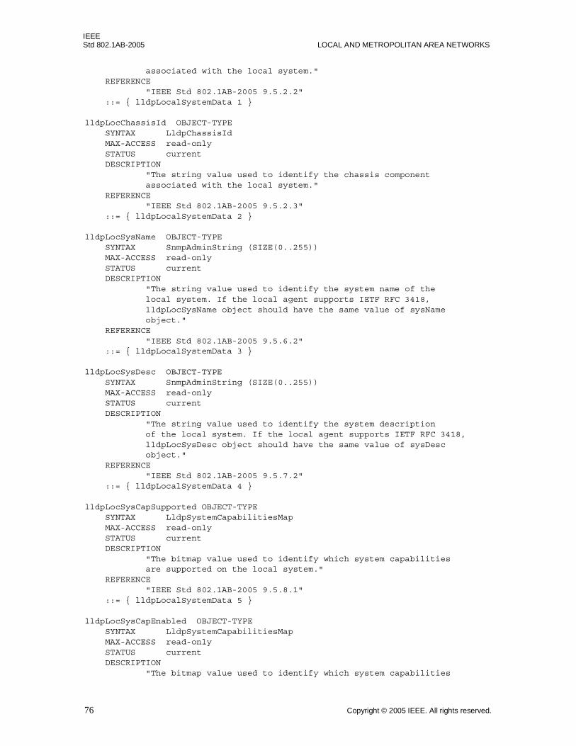
IEEEStd 802.1AB-2005 LOCAL AND METROPOLITAN AREA NETWORKS
associated with the local system." REFERENCE "IEEE Std 802.1AB-2005 9.5.2.2" ::= { lldpLocalSystemData 1 }
lldpLocChassisId OBJECT-TYPE SYNTAX LldpChassisId MAX-ACCESS read-only STATUS current DESCRIPTION "The string value used to identify the chassis component associated with the local system." REFERENCE "IEEE Std 802.1AB-2005 9.5.2.3" ::= { lldpLocalSystemData 2 }
lldpLocSysName OBJECT-TYPE SYNTAX SnmpAdminString (SIZE(0..255)) MAX-ACCESS read-only STATUS current DESCRIPTION "The string value used to identify the system name of the local system. If the local agent supports IETF RFC 3418, lldpLocSysName object should have the same value of sysName object." REFERENCE "IEEE Std 802.1AB-2005 9.5.6.2" ::= { lldpLocalSystemData 3 }
lldpLocSysDesc OBJECT-TYPE SYNTAX SnmpAdminString (SIZE(0..255)) MAX-ACCESS read-only STATUS current DESCRIPTION "The string value used to identify the system description of the local system. If the local agent supports IETF RFC 3418, lldpLocSysDesc object should have the same value of sysDesc object." REFERENCE "IEEE Std 802.1AB-2005 9.5.7.2" ::= { lldpLocalSystemData 4 }
lldpLocSysCapSupported OBJECT-TYPE SYNTAX LldpSystemCapabilitiesMap MAX-ACCESS read-only STATUS current DESCRIPTION "The bitmap value used to identify which system capabilities are supported on the local system." REFERENCE "IEEE Std 802.1AB-2005 9.5.8.1" ::= { lldpLocalSystemData 5 }
lldpLocSysCapEnabled OBJECT-TYPE SYNTAX LldpSystemCapabilitiesMap MAX-ACCESS read-only STATUS current DESCRIPTION "The bitmap value used to identify which system capabilities
76 Copyright © 2005 IEEE. All rights reserved.
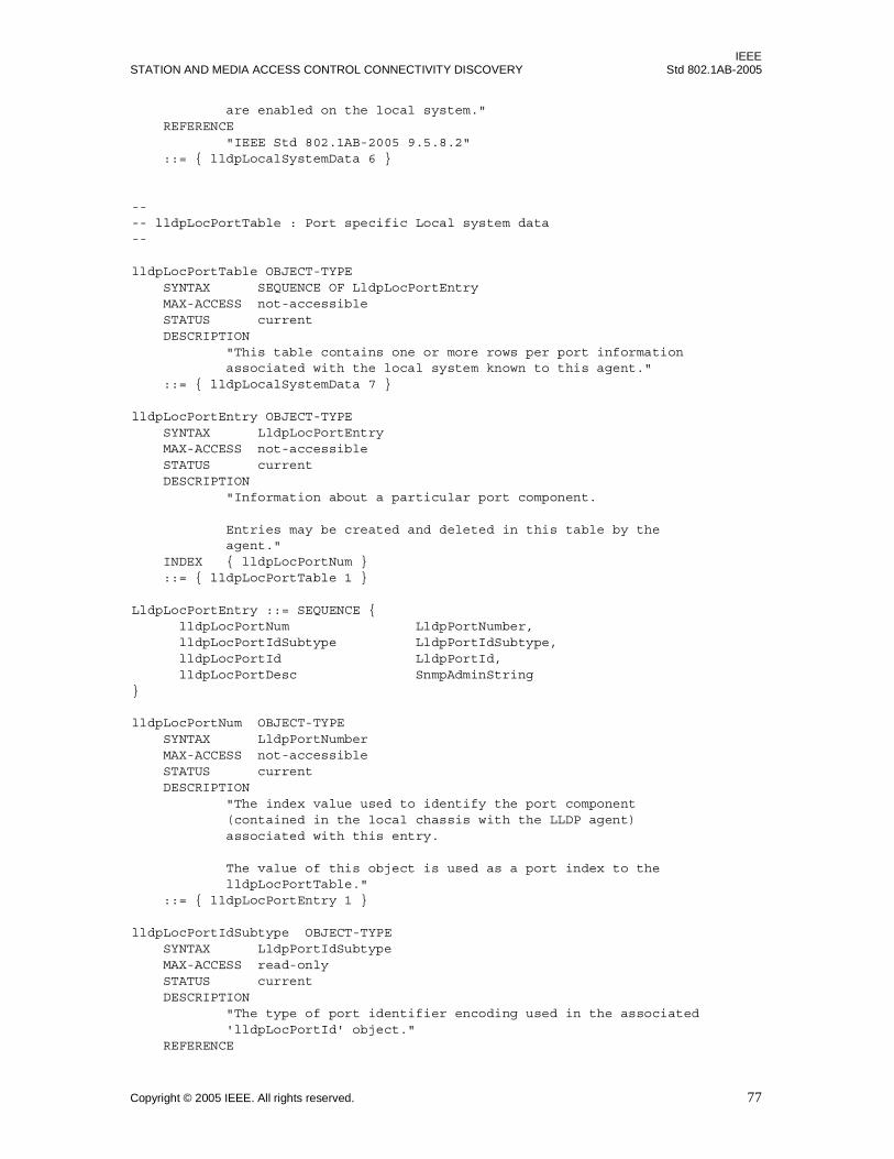
IEEESTATION AND MEDIA ACCESS CONTROL CONNECTIVITY DISCOVERY Std 802.1AB-2005
are enabled on the local system." REFERENCE "IEEE Std 802.1AB-2005 9.5.8.2" ::= { lldpLocalSystemData 6 }
---- lldpLocPortTable : Port specific Local system data--
lldpLocPortTable OBJECT-TYPE SYNTAX SEQUENCE OF LldpLocPortEntry MAX-ACCESS not-accessible STATUS current DESCRIPTION "This table contains one or more rows per port information associated with the local system known to this agent." ::= { lldpLocalSystemData 7 }
lldpLocPortEntry OBJECT-TYPE SYNTAX LldpLocPortEntry MAX-ACCESS not-accessible STATUS current DESCRIPTION "Information about a particular port component.
Entries may be created and deleted in this table by the agent." INDEX { lldpLocPortNum } ::= { lldpLocPortTable 1 }
LldpLocPortEntry ::= SEQUENCE { lldpLocPortNum LldpPortNumber, lldpLocPortIdSubtype LldpPortIdSubtype, lldpLocPortId LldpPortId, lldpLocPortDesc SnmpAdminString}
lldpLocPortNum OBJECT-TYPE SYNTAX LldpPortNumber MAX-ACCESS not-accessible STATUS current DESCRIPTION "The index value used to identify the port component (contained in the local chassis with the LLDP agent) associated with this entry. The value of this object is used as a port index to the lldpLocPortTable." ::= { lldpLocPortEntry 1 }
lldpLocPortIdSubtype OBJECT-TYPE SYNTAX LldpPortIdSubtype MAX-ACCESS read-only STATUS current DESCRIPTION "The type of port identifier encoding used in the associated 'lldpLocPortId' object." REFERENCE
Copyright © 2005 IEEE. All rights reserved. 77

IEEEStd 802.1AB-2005 LOCAL AND METROPOLITAN AREA NETWORKS
"IEEE Std 802.1AB-2005 9.5.3.2" ::= { lldpLocPortEntry 2 }
lldpLocPortId OBJECT-TYPE SYNTAX LldpPortId MAX-ACCESS read-only STATUS current DESCRIPTION "The string value used to identify the port component associated with a given port in the local system." REFERENCE "IEEE Std 802.1AB-2005 9.5.3.3" ::= { lldpLocPortEntry 3 }
lldpLocPortDesc OBJECT-TYPE SYNTAX SnmpAdminString (SIZE(0..255)) MAX-ACCESS read-only STATUS current DESCRIPTION "The string value used to identify the IEEE 802 LAN station's port description associated with the local system. If the local agent supports IETF RFC 2863, lldpLocPortDesc object should have the same value of ifDescr object." REFERENCE "IEEE Std 802.1AB-2005 9.5.5.2" ::= { lldpLocPortEntry 4 }
---- lldpLocManAddrTable : Management addresses of the local system--
lldpLocManAddrTable OBJECT-TYPE SYNTAX SEQUENCE OF LldpLocManAddrEntry MAX-ACCESS not-accessible STATUS current DESCRIPTION "This table contains management address information on the local system known to this agent." ::= { lldpLocalSystemData 8 }
lldpLocManAddrEntry OBJECT-TYPE SYNTAX LldpLocManAddrEntry MAX-ACCESS not-accessible STATUS current DESCRIPTION "Management address information about a particular chassis component. There may be multiple management addresses configured on the system identified by a particular lldpLocChassisId. Each management address should have distinct 'management address type' (lldpLocManAddrSubtype) and 'management address' (lldpLocManAddr.)
Entries may be created and deleted in this table by the agent." INDEX { lldpLocManAddrSubtype, lldpLocManAddr } ::= { lldpLocManAddrTable 1 }
LldpLocManAddrEntry ::= SEQUENCE {
78 Copyright © 2005 IEEE. All rights reserved.
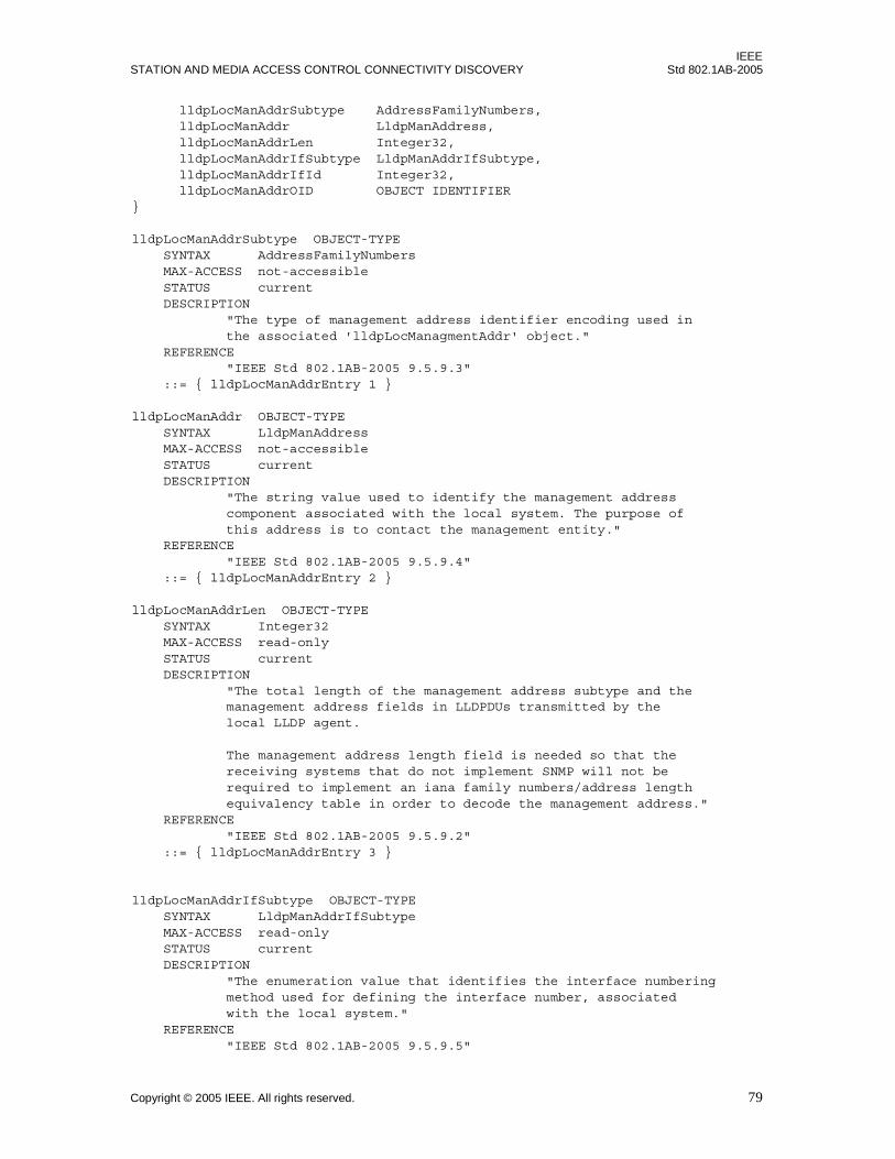
IEEESTATION AND MEDIA ACCESS CONTROL CONNECTIVITY DISCOVERY Std 802.1AB-2005
lldpLocManAddrSubtype AddressFamilyNumbers, lldpLocManAddr LldpManAddress, lldpLocManAddrLen Integer32, lldpLocManAddrIfSubtype LldpManAddrIfSubtype, lldpLocManAddrIfId Integer32, lldpLocManAddrOID OBJECT IDENTIFIER}
lldpLocManAddrSubtype OBJECT-TYPE SYNTAX AddressFamilyNumbers MAX-ACCESS not-accessible STATUS current DESCRIPTION "The type of management address identifier encoding used in the associated 'lldpLocManagmentAddr' object." REFERENCE "IEEE Std 802.1AB-2005 9.5.9.3" ::= { lldpLocManAddrEntry 1 }
lldpLocManAddr OBJECT-TYPE SYNTAX LldpManAddress MAX-ACCESS not-accessible STATUS current DESCRIPTION "The string value used to identify the management address component associated with the local system. The purpose of this address is to contact the management entity." REFERENCE "IEEE Std 802.1AB-2005 9.5.9.4" ::= { lldpLocManAddrEntry 2 }
lldpLocManAddrLen OBJECT-TYPE SYNTAX Integer32 MAX-ACCESS read-only STATUS current DESCRIPTION "The total length of the management address subtype and the management address fields in LLDPDUs transmitted by the local LLDP agent.
The management address length field is needed so that the receiving systems that do not implement SNMP will not be required to implement an iana family numbers/address length equivalency table in order to decode the management address." REFERENCE "IEEE Std 802.1AB-2005 9.5.9.2" ::= { lldpLocManAddrEntry 3 }
lldpLocManAddrIfSubtype OBJECT-TYPE SYNTAX LldpManAddrIfSubtype MAX-ACCESS read-only STATUS current DESCRIPTION "The enumeration value that identifies the interface numbering method used for defining the interface number, associated with the local system." REFERENCE "IEEE Std 802.1AB-2005 9.5.9.5"
Copyright © 2005 IEEE. All rights reserved. 79

IEEEStd 802.1AB-2005 LOCAL AND METROPOLITAN AREA NETWORKS
::= { lldpLocManAddrEntry 4 }
lldpLocManAddrIfId OBJECT-TYPE SYNTAX Integer32 MAX-ACCESS read-only STATUS current DESCRIPTION "The integer value used to identify the interface number regarding the management address component associated with the local system." REFERENCE "IEEE Std 802.1AB-2005 9.5.9.6" ::= { lldpLocManAddrEntry 5 }
lldpLocManAddrOID OBJECT-TYPE SYNTAX OBJECT IDENTIFIER MAX-ACCESS read-only STATUS current DESCRIPTION "The OID value used to identify the type of hardware component or protocol entity associated with the management address advertised by the local system agent." REFERENCE "IEEE Std 802.1AB-2005 9.5.9.8" ::= { lldpLocManAddrEntry 6 }
-- ***********************************************************---- R E M O T E S Y S T E M S D A T A---- ***********************************************************
lldpRemTable OBJECT-TYPE SYNTAX SEQUENCE OF LldpRemEntry MAX-ACCESS not-accessible STATUS current DESCRIPTION "This table contains one or more rows per physical network connection known to this agent. The agent may wish to ensure that only one lldpRemEntry is present for each local port, or it may choose to maintain multiple lldpRemEntries for the same local port.
The following procedure may be used to retrieve remote systems information updates from an LLDP agent:
1. NMS polls all tables associated with remote systems and keeps a local copy of the information retrieved. NMS polls periodically the values of the following objects: a. lldpStatsRemTablesInserts b. lldpStatsRemTablesDeletes c. lldpStatsRemTablesDrops d. lldpStatsRemTablesAgeouts e. lldpStatsRxPortAgeoutsTotal for all ports.
2. LLDP agent updates remote systems MIB objects, and sends out notifications to a list of notification
80 Copyright © 2005 IEEE. All rights reserved.
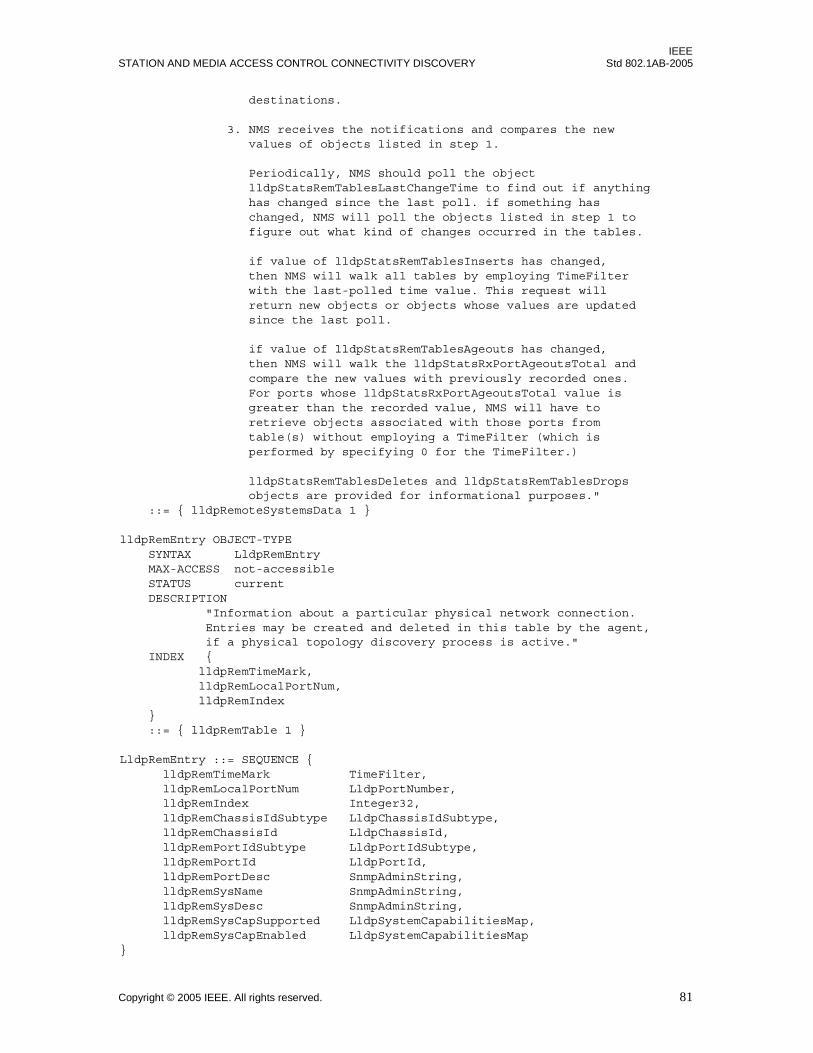
IEEESTATION AND MEDIA ACCESS CONTROL CONNECTIVITY DISCOVERY Std 802.1AB-2005
destinations.
3. NMS receives the notifications and compares the new values of objects listed in step 1.
Periodically, NMS should poll the object lldpStatsRemTablesLastChangeTime to find out if anything has changed since the last poll. if something has changed, NMS will poll the objects listed in step 1 to figure out what kind of changes occurred in the tables.
if value of lldpStatsRemTablesInserts has changed, then NMS will walk all tables by employing TimeFilter with the last-polled time value. This request will return new objects or objects whose values are updated since the last poll.
if value of lldpStatsRemTablesAgeouts has changed, then NMS will walk the lldpStatsRxPortAgeoutsTotal and compare the new values with previously recorded ones. For ports whose lldpStatsRxPortAgeoutsTotal value is greater than the recorded value, NMS will have to retrieve objects associated with those ports from table(s) without employing a TimeFilter (which is performed by specifying 0 for the TimeFilter.)
lldpStatsRemTablesDeletes and lldpStatsRemTablesDrops objects are provided for informational purposes." ::= { lldpRemoteSystemsData 1 }
lldpRemEntry OBJECT-TYPE SYNTAX LldpRemEntry MAX-ACCESS not-accessible STATUS current DESCRIPTION "Information about a particular physical network connection. Entries may be created and deleted in this table by the agent, if a physical topology discovery process is active." INDEX { lldpRemTimeMark, lldpRemLocalPortNum, lldpRemIndex } ::= { lldpRemTable 1 }
LldpRemEntry ::= SEQUENCE { lldpRemTimeMark TimeFilter, lldpRemLocalPortNum LldpPortNumber, lldpRemIndex Integer32, lldpRemChassisIdSubtype LldpChassisIdSubtype, lldpRemChassisId LldpChassisId, lldpRemPortIdSubtype LldpPortIdSubtype, lldpRemPortId LldpPortId, lldpRemPortDesc SnmpAdminString, lldpRemSysName SnmpAdminString, lldpRemSysDesc SnmpAdminString, lldpRemSysCapSupported LldpSystemCapabilitiesMap, lldpRemSysCapEnabled LldpSystemCapabilitiesMap}
Copyright © 2005 IEEE. All rights reserved. 81

IEEEStd 802.1AB-2005 LOCAL AND METROPOLITAN AREA NETWORKS
lldpRemTimeMark OBJECT-TYPE SYNTAX TimeFilter MAX-ACCESS not-accessible STATUS current DESCRIPTION "A TimeFilter for this entry. See the TimeFilter textual convention in IETF RFC 2021 and http://www.ietf.org/IESG/Implementations/RFC2021-Implementation.txt to see how TimeFilter works." REFERENCE "IETF RFC 2021 section 6" ::= { lldpRemEntry 1 }
lldpRemLocalPortNum OBJECT-TYPE SYNTAX LldpPortNumber MAX-ACCESS not-accessible STATUS current DESCRIPTION "The index value used to identify the port component (contained in the local chassis with the LLDP agent) associated with this entry. The lldpRemLocalPortNum identifies the port on which the remote system information is received.
The value of this object is used as a port index to the lldpRemTable." ::= { lldpRemEntry 2 }
lldpRemIndex OBJECT-TYPE SYNTAX Integer32(1..2147483647) MAX-ACCESS not-accessible STATUS current DESCRIPTION "This object represents an arbitrary local integer value used by this agent to identify a particular connection instance, unique only for the indicated remote system.
An agent is encouraged to assign monotonically increasing index values to new entries, starting with one, after each reboot. It is considered unlikely that the lldpRemIndex will wrap between reboots." ::= { lldpRemEntry 3 }
lldpRemChassisIdSubtype OBJECT-TYPE SYNTAX LldpChassisIdSubtype MAX-ACCESS read-only STATUS current DESCRIPTION "The type of encoding used to identify the chassis associated with the remote system." REFERENCE "IEEE Std 802.1AB-2005 9.5.2.2" ::= { lldpRemEntry 4 }
lldpRemChassisId OBJECT-TYPE SYNTAX LldpChassisId MAX-ACCESS read-only STATUS current
82 Copyright © 2005 IEEE. All rights reserved.

IEEESTATION AND MEDIA ACCESS CONTROL CONNECTIVITY DISCOVERY Std 802.1AB-2005
DESCRIPTION "The string value used to identify the chassis component associated with the remote system." REFERENCE "IEEE Std 802.1AB-2005 9.5.2.3" ::= { lldpRemEntry 5 }
lldpRemPortIdSubtype OBJECT-TYPE SYNTAX LldpPortIdSubtype MAX-ACCESS read-only STATUS current DESCRIPTION "The type of port identifier encoding used in the associated 'lldpRemPortId' object." REFERENCE "IEEE Std 802.1AB-2005 9.5.3.2" ::= { lldpRemEntry 6 }
lldpRemPortId OBJECT-TYPE SYNTAX LldpPortId MAX-ACCESS read-only STATUS current DESCRIPTION "The string value used to identify the port component associated with the remote system." REFERENCE "IEEE Std 802.1AB-2005 9.5.3.3" ::= { lldpRemEntry 7 }
lldpRemPortDesc OBJECT-TYPE SYNTAX SnmpAdminString (SIZE(0..255)) MAX-ACCESS read-only STATUS current DESCRIPTION "The string value used to identify the description of the given port associated with the remote system." REFERENCE "IEEE Std 802.1AB-2005 9.5.5.2" ::= { lldpRemEntry 8 }
lldpRemSysName OBJECT-TYPE SYNTAX SnmpAdminString (SIZE(0..255)) MAX-ACCESS read-only STATUS current DESCRIPTION "The string value used to identify the system name of the remote system." REFERENCE "IEEE Std 802.1AB-2005 9.5.6.2" ::= { lldpRemEntry 9 }
lldpRemSysDesc OBJECT-TYPE SYNTAX SnmpAdminString (SIZE(0..255)) MAX-ACCESS read-only STATUS current DESCRIPTION "The string value used to identify the system description of the remote system." REFERENCE
Copyright © 2005 IEEE. All rights reserved. 83

IEEEStd 802.1AB-2005 LOCAL AND METROPOLITAN AREA NETWORKS
"IEEE Std 802.1AB-2005 9.5.7.2" ::= { lldpRemEntry 10 }
lldpRemSysCapSupported OBJECT-TYPE SYNTAX LldpSystemCapabilitiesMap MAX-ACCESS read-only STATUS current DESCRIPTION "The bitmap value used to identify which system capabilities are supported on the remote system." REFERENCE "IEEE Std 802.1AB-2005 9.5.8.1" ::= { lldpRemEntry 11 }
lldpRemSysCapEnabled OBJECT-TYPE SYNTAX LldpSystemCapabilitiesMap MAX-ACCESS read-only STATUS current DESCRIPTION "The bitmap value used to identify which system capabilities are enabled on the remote system." REFERENCE "IEEE Std 802.1AB-2005 9.5.8.2" ::= { lldpRemEntry 12 }
---- lldpRemManAddrTable : Management addresses of the remote system--
lldpRemManAddrTable OBJECT-TYPE SYNTAX SEQUENCE OF LldpRemManAddrEntry MAX-ACCESS not-accessible STATUS current DESCRIPTION "This table contains one or more rows per management address information on the remote system learned on a particular port contained in the local chassis known to this agent." ::= { lldpRemoteSystemsData 2 }
lldpRemManAddrEntry OBJECT-TYPE SYNTAX LldpRemManAddrEntry MAX-ACCESS not-accessible STATUS current DESCRIPTION "Management address information about a particular chassis component. There may be multiple management addresses configured on the remote system identified by a particular lldpRemIndex whose information is received on lldpRemLocalPortNum of the local system. Each management address should have distinct 'management address type' (lldpRemManAddrSubtype) and 'management address' (lldpRemManAddr.)
Entries may be created and deleted in this table by the agent." INDEX { lldpRemTimeMark, lldpRemLocalPortNum, lldpRemIndex, lldpRemManAddrSubtype,
84 Copyright © 2005 IEEE. All rights reserved.
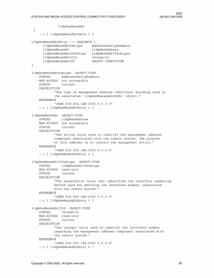
IEEESTATION AND MEDIA ACCESS CONTROL CONNECTIVITY DISCOVERY Std 802.1AB-2005
lldpRemManAddr } ::= { lldpRemManAddrTable 1 }
LldpRemManAddrEntry ::= SEQUENCE { lldpRemManAddrSubtype AddressFamilyNumbers, lldpRemManAddr LldpManAddress, lldpRemManAddrIfSubtype LldpManAddrIfSubtype, lldpRemManAddrIfId Integer32, lldpRemManAddrOID OBJECT IDENTIFIER}
lldpRemManAddrSubtype OBJECT-TYPE SYNTAX AddressFamilyNumbers MAX-ACCESS not-accessible STATUS current DESCRIPTION "The type of management address identifier encoding used in the associated 'lldpRemManagmentAddr' object." REFERENCE "IEEE Std 802.1AB-2005 9.5.9.3" ::= { lldpRemManAddrEntry 1 }
lldpRemManAddr OBJECT-TYPE SYNTAX LldpManAddress MAX-ACCESS not-accessible STATUS current DESCRIPTION "The string value used to identify the management address component associated with the remote system. The purpose of this address is to contact the management entity." REFERENCE "IEEE Std 802.1AB-2005 9.5.9.4" ::= { lldpRemManAddrEntry 2 }
lldpRemManAddrIfSubtype OBJECT-TYPE SYNTAX LldpManAddrIfSubtype MAX-ACCESS read-only STATUS current DESCRIPTION "The enumeration value that identifies the interface numbering method used for defining the interface number, associated with the remote system." REFERENCE "IEEE Std 802.1AB-2005 9.5.9.5" ::= { lldpRemManAddrEntry 3 }
lldpRemManAddrIfId OBJECT-TYPE SYNTAX Integer32 MAX-ACCESS read-only STATUS current DESCRIPTION "The integer value used to identify the interface number regarding the management address component associated with the remote system." REFERENCE "IEEE Std 802.1AB-2005 9.5.9.6" ::= { lldpRemManAddrEntry 4 }
Copyright © 2005 IEEE. All rights reserved. 85
IEEEStd 802.1AB-2005 LOCAL AND METROPOLITAN AREA NETWORKS
lldpRemManAddrOID OBJECT-TYPE SYNTAX OBJECT IDENTIFIER MAX-ACCESS read-only STATUS current DESCRIPTION "The OID value used to identify the type of hardware component or protocol entity associated with the management address advertised by the remote system agent." REFERENCE "IEEE Std 802.1AB-2005 9.5.9.8" ::= { lldpRemManAddrEntry 5 }
---- lldpRemUnknownTLVTable : Unrecognized TLV information --lldpRemUnknownTLVTable OBJECT-TYPE SYNTAX SEQUENCE OF LldpRemUnknownTLVEntry MAX-ACCESS not-accessible STATUS current DESCRIPTION "This table contains information about an incoming TLV which is not recognized by the receiving LLDP agent. The TLV may be from a later version of the basic management set.
This table should only contain TLVs that are found in a single LLDP frame. Entries in this table, associated with an MAC service access point (MSAP, the access point for MAC services provided to the LCC sublayer, defined in IEEE 100, which is also identified with a particular lldpRemLocalPortNum, lldpRemIndex pair) are overwritten with most recently received unrecognized TLV from the same MSAP, or they will naturally age out when the rxInfoTTL timer (associated with the MSAP) expires." REFERENCE "IEEE Std 802.1AB-2005 10.3.2" ::= { lldpRemoteSystemsData 3 }
lldpRemUnknownTLVEntry OBJECT-TYPE SYNTAX LldpRemUnknownTLVEntry MAX-ACCESS not-accessible STATUS current DESCRIPTION "Information about an unrecognized TLV received from a physical network connection. Entries may be created and deleted in this table by the agent, if a physical topology discovery process is active." INDEX { lldpRemTimeMark, lldpRemLocalPortNum, lldpRemIndex, lldpRemUnknownTLVType } ::= { lldpRemUnknownTLVTable 1 }
LldpRemUnknownTLVEntry ::= SEQUENCE { lldpRemUnknownTLVType Integer32, lldpRemUnknownTLVInfo OCTET STRING}
86 Copyright © 2005 IEEE. All rights reserved.
IEEESTATION AND MEDIA ACCESS CONTROL CONNECTIVITY DISCOVERY Std 802.1AB-2005
lldpRemUnknownTLVType OBJECT-TYPE SYNTAX Integer32(9..126) MAX-ACCESS not-accessible STATUS current DESCRIPTION "This object represents the value extracted from the type field of the TLV." REFERENCE "IEEE Std 802.1AB-2005 10.3.5" ::= { lldpRemUnknownTLVEntry 1 }
lldpRemUnknownTLVInfo OBJECT-TYPE SYNTAX OCTET STRING (SIZE(0..511)) MAX-ACCESS read-only STATUS current DESCRIPTION "This object represents the value extracted from the value field of the TLV." REFERENCE "IEEE Std 802.1AB-2005 10.3.5" ::= { lldpRemUnknownTLVEntry 2 }
-------------------------------------------------------------------------------- Remote Systems Extension Table - Organizationally-Defined Information ------------------------------------------------------------------------------lldpRemOrgDefInfoTable OBJECT-TYPE SYNTAX SEQUENCE OF LldpRemOrgDefInfoEntry MAX-ACCESS not-accessible STATUS current DESCRIPTION "This table contains one or more rows per physical network connection which advertises the organizationally defined information.
Note that this table contains one or more rows of organizationally defined information that is not recognized by the local agent.
If the local system is capable of recognizing any organizationally defined information, appropriate extension MIBs from the organization should be used for information retrieval." ::= { lldpRemoteSystemsData 4 }
lldpRemOrgDefInfoEntry OBJECT-TYPE SYNTAX LldpRemOrgDefInfoEntry MAX-ACCESS not-accessible STATUS current DESCRIPTION "Information about the unrecognized organizationally defined information advertised by the remote system. The lldpRemTimeMark, lldpRemLocalPortNum, lldpRemIndex, lldpRemOrgDefInfoOUI, lldpRemOrgDefInfoSubtype, and lldpRemOrgDefInfoIndex are indexes to this table. If there is an lldpRemOrgDefInfoEntry associated with a particular remote system identified by the lldpRemLocalPortNum and lldpRemIndex, there must be an lldpRemEntry associated with the same instance (i.e, using same indexes.) When the lldpRemEntry for the same index is removed from the lldpRemTable, the
Copyright © 2005 IEEE. All rights reserved. 87
IEEEStd 802.1AB-2005 LOCAL AND METROPOLITAN AREA NETWORKS
associated lldpRemOrgDefInfoEntry should be removed from the lldpRemOrgDefInfoTable.
Entries may be created and deleted in this table by the agent." INDEX { lldpRemTimeMark, lldpRemLocalPortNum, lldpRemIndex, lldpRemOrgDefInfoOUI, lldpRemOrgDefInfoSubtype, lldpRemOrgDefInfoIndex } ::= { lldpRemOrgDefInfoTable 1 }
LldpRemOrgDefInfoEntry ::= SEQUENCE { lldpRemOrgDefInfoOUI OCTET STRING, lldpRemOrgDefInfoSubtype Integer32, lldpRemOrgDefInfoIndex Integer32, lldpRemOrgDefInfo OCTET STRING}
lldpRemOrgDefInfoOUI OBJECT-TYPE SYNTAX OCTET STRING (SIZE(3)) MAX-ACCESS not-accessible STATUS current DESCRIPTION "The Organizationally Unique Identifier (OUI), as defined in IEEE Std 802-2001, is a 24 bit (three octets) globally unique assigned number referenced by various standards, of the information received from the remote system." REFERENCE "IEEE Std 802.1AB-2005 9.6.1.3" ::= { lldpRemOrgDefInfoEntry 1 }
lldpRemOrgDefInfoSubtype OBJECT-TYPE SYNTAX Integer32(1..255) MAX-ACCESS not-accessible STATUS current DESCRIPTION "The integer value used to identify the subtype of the organizationally defined information received from the remote system.
The subtype value is required to identify different instances of organizationally defined information that could not be retrieved without a unique identifier that indicates the particular type of information contained in the information string." REFERENCE "IEEE Std 802.1AB-2005 9.6.1.4" ::= { lldpRemOrgDefInfoEntry 2 }
lldpRemOrgDefInfoIndex OBJECT-TYPE SYNTAX Integer32(1..2147483647) MAX-ACCESS not-accessible STATUS current DESCRIPTION "This object represents an arbitrary local integer value used by this agent to identify a particular unrecognized organizationally defined information instance, unique only
88 Copyright © 2005 IEEE. All rights reserved.
IEEESTATION AND MEDIA ACCESS CONTROL CONNECTIVITY DISCOVERY Std 802.1AB-2005
for the lldpRemOrgDefInfoOUI and lldpRemOrgDefInfoSubtype from the same remote system.
An agent is encouraged to assign monotonically increasing index values to new entries, starting with one, after each reboot. It is considered unlikely that the lldpRemOrgDefInfoIndex will wrap between reboots." ::= { lldpRemOrgDefInfoEntry 3 }
lldpRemOrgDefInfo OBJECT-TYPE SYNTAX OCTET STRING(SIZE(0..507)) MAX-ACCESS read-only STATUS current DESCRIPTION "The string value used to identify the organizationally defined information of the remote system. The encoding for this object should be as defined for SnmpAdminString TC." REFERENCE "IEEE Std 802.1AB-2005 9.6.1.5" ::= { lldpRemOrgDefInfoEntry 4 }
---- ***********************************************************-- -- L L D P M I B N O T I F I C A T I O N S-- -- *********************************************************** --
lldpNotificationPrefix OBJECT IDENTIFIER ::= { lldpNotifications 0 }
lldpRemTablesChange NOTIFICATION-TYPE OBJECTS { lldpStatsRemTablesInserts, lldpStatsRemTablesDeletes, lldpStatsRemTablesDrops, lldpStatsRemTablesAgeouts } STATUS current DESCRIPTION "A lldpRemTablesChange notification is sent when the value of lldpStatsRemTableLastChangeTime changes. It can be utilized by an NMS to trigger LLDP remote systems table maintenance polls.
Note that transmission of lldpRemTablesChange notifications are throttled by the agent, as specified by the 'lldpNotificationInterval' object." ::= { lldpNotificationPrefix 1 }
---- ***********************************************************-- -- L L D P M I B C O N F O R M A N C E -- -- *********************************************************** --
Copyright © 2005 IEEE. All rights reserved. 89

IEEEStd 802.1AB-2005 LOCAL AND METROPOLITAN AREA NETWORKS
lldpCompliances OBJECT IDENTIFIER ::= { lldpConformance 1 }lldpGroups OBJECT IDENTIFIER ::= { lldpConformance 2 }
-- compliance statements
lldpCompliance MODULE-COMPLIANCE STATUS current DESCRIPTION "The compliance statement for SNMP entities which implement the LLDP MIB." MODULE -- this module MANDATORY-GROUPS { lldpConfigGroup, lldpConfigRxGroup, lldpConfigTxGroup, lldpStatsRxGroup, lldpStatsTxGroup, lldpLocSysGroup, lldpRemSysGroup, lldpNotificationsGroup } ::= { lldpCompliances 1 }
-- MIB groupings
lldpConfigGroup OBJECT-GROUP OBJECTS { lldpPortConfigAdminStatus } STATUS current DESCRIPTION "The collection of objects which are used to configure the LLDP implementation behavior.
This group is mandatory for agents which implement the LLDP." ::= { lldpGroups 1 }
lldpConfigRxGroup OBJECT-GROUP OBJECTS { lldpNotificationInterval, lldpPortConfigNotificationEnable } STATUS current DESCRIPTION "The collection of objects which are used to configure the LLDP implementation behavior.
This group is mandatory for agents which implement the LLDP and have the capability of receiving LLDP frames." ::= { lldpGroups 2 }
lldpConfigTxGroup OBJECT-GROUP OBJECTS { lldpMessageTxInterval, lldpMessageTxHoldMultiplier, lldpReinitDelay, lldpTxDelay, lldpPortConfigTLVsTxEnable, lldpConfigManAddrPortsTxEnable
90 Copyright © 2005 IEEE. All rights reserved.
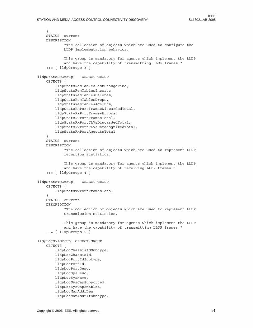
IEEESTATION AND MEDIA ACCESS CONTROL CONNECTIVITY DISCOVERY Std 802.1AB-2005
} STATUS current DESCRIPTION "The collection of objects which are used to configure the LLDP implementation behavior.
This group is mandatory for agents which implement the LLDP and have the capability of transmitting LLDP frames." ::= { lldpGroups 3 }
lldpStatsRxGroup OBJECT-GROUP OBJECTS { lldpStatsRemTablesLastChangeTime, lldpStatsRemTablesInserts, lldpStatsRemTablesDeletes, lldpStatsRemTablesDrops, lldpStatsRemTablesAgeouts, lldpStatsRxPortFramesDiscardedTotal, lldpStatsRxPortFramesErrors, lldpStatsRxPortFramesTotal, lldpStatsRxPortTLVsDiscardedTotal, lldpStatsRxPortTLVsUnrecognizedTotal, lldpStatsRxPortAgeoutsTotal } STATUS current DESCRIPTION "The collection of objects which are used to represent LLDP reception statistics.
This group is mandatory for agents which implement the LLDP and have the capability of receiving LLDP frames." ::= { lldpGroups 4 }
lldpStatsTxGroup OBJECT-GROUP OBJECTS { lldpStatsTxPortFramesTotal } STATUS current DESCRIPTION "The collection of objects which are used to represent LLDP transmission statistics.
This group is mandatory for agents which implement the LLDP and have the capability of transmitting LLDP frames." ::= { lldpGroups 5 }
lldpLocSysGroup OBJECT-GROUP OBJECTS { lldpLocChassisIdSubtype, lldpLocChassisId, lldpLocPortIdSubtype, lldpLocPortId, lldpLocPortDesc, lldpLocSysDesc, lldpLocSysName, lldpLocSysCapSupported, lldpLocSysCapEnabled, lldpLocManAddrLen, lldpLocManAddrIfSubtype,
Copyright © 2005 IEEE. All rights reserved. 91
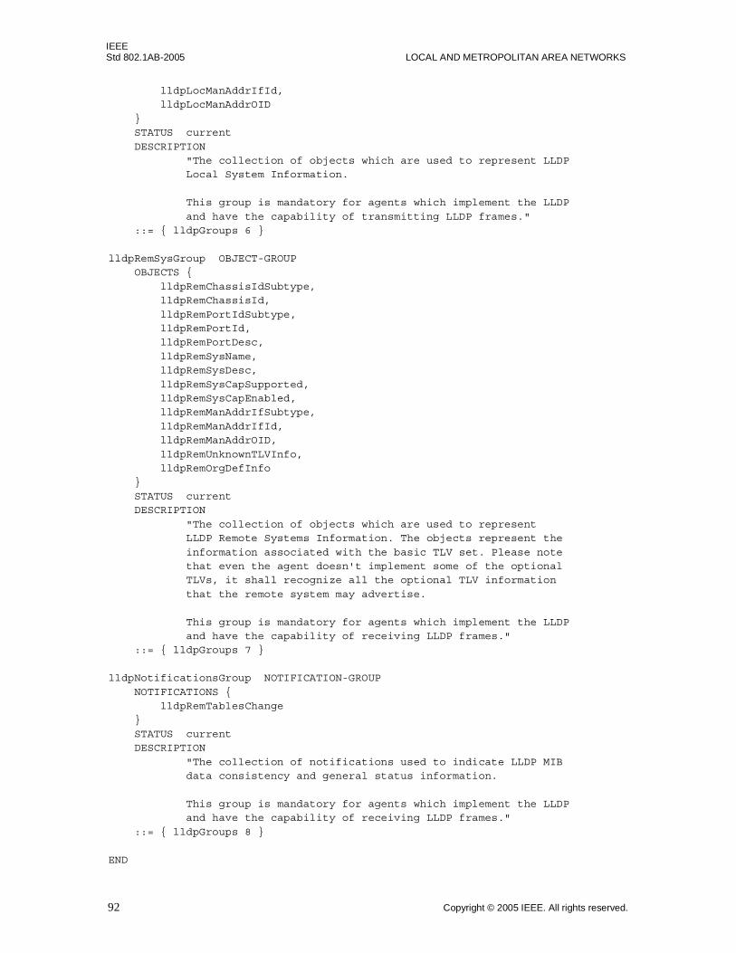
IEEEStd 802.1AB-2005 LOCAL AND METROPOLITAN AREA NETWORKS
lldpLocManAddrIfId, lldpLocManAddrOID
} STATUS current
DESCRIPTION "The collection of objects which are used to represent LLDP Local System Information.
This group is mandatory for agents which implement the LLDP
and have the capability of transmitting LLDP frames." ::= { lldpGroups 6 }
lldpRemSysGroup OBJECT-GROUP OBJECTS {
lldpRemChassisIdSubtype, lldpRemChassisId,
lldpRemPortIdSubtype, lldpRemPortId, lldpRemPortDesc,
lldpRemSysName, lldpRemSysDesc,
lldpRemSysCapSupported, lldpRemSysCapEnabled, lldpRemManAddrIfSubtype,
lldpRemManAddrIfId, lldpRemManAddrOID,
lldpRemUnknownTLVInfo, lldpRemOrgDefInfo }
STATUS current DESCRIPTION
"The collection of objects which are used to represent LLDP Remote Systems Information. The objects represent the
information associated with the basic TLV set. Please note that even the agent doesn't implement some of the optional TLVs, it shall recognize all the optional TLV information
that the remote system may advertise.
This group is mandatory for agents which implement the LLDP and have the capability of receiving LLDP frames." ::= { lldpGroups 7 }
lldpNotificationsGroup NOTIFICATION-GROUP
NOTIFICATIONS { lldpRemTablesChange }
STATUS current DESCRIPTION
"The collection of notifications used to indicate LLDP MIB data consistency and general status information.
This group is mandatory for agents which implement the LLDP and have the capability of receiving LLDP frames."
::= { lldpGroups 8 }
END
92 Copyright © 2005 IEEE. All rights reserved.
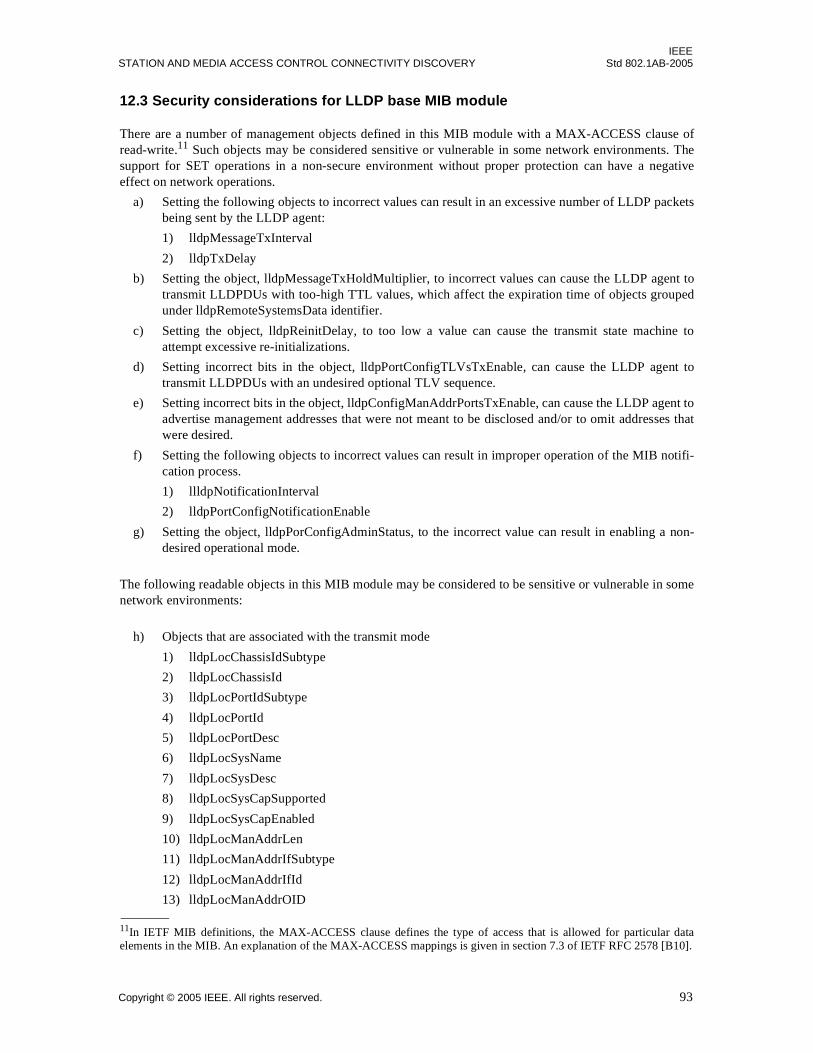
IEEESTATION AND MEDIA ACCESS CONTROL CONNECTIVITY DISCOVERY Std 802.1AB-2005
12.3 Security considerations for LLDP base MIB module
There are a number of management objects defined in this MIB module with a MAX-ACCESS clause ofread-write.11 Such objects may be considered sensitive or vulnerable in some network environments. Thesupport for SET operations in a non-secure environment without proper protection can have a negativeeffect on network operations.
a) Setting the following objects to incorrect values can result in an excessive number of LLDP packetsbeing sent by the LLDP agent:
1) lldpMessageTxInterval
2) lldpTxDelay
b) Setting the object, lldpMessageTxHoldMultiplier, to incorrect values can cause the LLDP agent totransmit LLDPDUs with too-high TTL values, which affect the expiration time of objects groupedunder lldpRemoteSystemsData identifier.
c) Setting the object, lldpReinitDelay, to too low a value can cause the transmit state machine toattempt excessive re-initializations.
d) Setting incorrect bits in the object, lldpPortConfigTLVsTxEnable, can cause the LLDP agent totransmit LLDPDUs with an undesired optional TLV sequence.
e) Setting incorrect bits in the object, lldpConfigManAddrPortsTxEnable, can cause the LLDP agent toadvertise management addresses that were not meant to be disclosed and/or to omit addresses thatwere desired.
f) Setting the following objects to incorrect values can result in improper operation of the MIB notifi-cation process.
1) llldpNotificationInterval
2) lldpPortConfigNotificationEnable
g) Setting the object, lldpPorConfigAdminStatus, to the incorrect value can result in enabling a non-desired operational mode.
The following readable objects in this MIB module may be considered to be sensitive or vulnerable in somenetwork environments:
h) Objects that are associated with the transmit mode
1) lldpLocChassisIdSubtype
2) lldpLocChassisId
3) lldpLocPortIdSubtype
4) lldpLocPortId
5) lldpLocPortDesc
6) lldpLocSysName
7) lldpLocSysDesc
8) lldpLocSysCapSupported
9) lldpLocSysCapEnabled
10) lldpLocManAddrLen
11) lldpLocManAddrIfSubtype
12) lldpLocManAddrIfId
13) lldpLocManAddrOID
11In IETF MIB definitions, the MAX-ACCESS clause defines the type of access that is allowed for particular dataelements in the MIB. An explanation of the MAX-ACCESS mappings is given in section 7.3 of IETF RFC 2578 [B10].
Copyright © 2005 IEEE. All rights reserved. 93
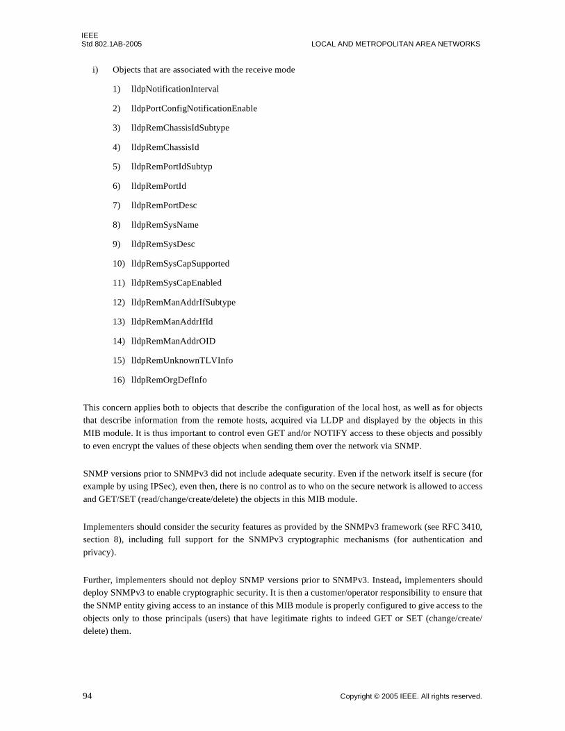
IEEEStd 802.1AB-2005 LOCAL AND METROPOLITAN AREA NETWORKS
i) Objects that are associated with the receive mode
1) lldpNotificationInterval
2) lldpPortConfigNotificationEnable
3) lldpRemChassisIdSubtype
4) lldpRemChassisId
5) lldpRemPortIdSubtyp
6) lldpRemPortId
7) lldpRemPortDesc
8) lldpRemSysName
9) lldpRemSysDesc
10) lldpRemSysCapSupported
11) lldpRemSysCapEnabled
12) lldpRemManAddrIfSubtype
13) lldpRemManAddrIfId
14) lldpRemManAddrOID
15) lldpRemUnknownTLVInfo
16) lldpRemOrgDefInfo
This concern applies both to objects that describe the configuration of the local host, as well as for objectsthat describe information from the remote hosts, acquired via LLDP and displayed by the objects in this
MIB module. It is thus important to control even GET and/or NOTIFY access to these objects and possibly
to even encrypt the values of these objects when sending them over the network via SNMP.
SNMP versions prior to SNMPv3 did not include adequate security. Even if the network itself is secure (forexample by using IPSec), even then, there is no control as to who on the secure network is allowed to access
and GET/SET (read/change/create/delete) the objects in this MIB module.
Implementers should consider the security features as provided by the SNMPv3 framework (see RFC 3410,section 8), including full support for the SNMPv3 cryptographic mechanisms (for authentication and
privacy).
Further, implementers should not deploy SNMP versions prior to SNMPv3. Instead, implementers shoulddeploy SNMPv3 to enable cryptographic security. It is then a customer/operator responsibility to ensure that
the SNMP entity giving access to an instance of this MIB module is properly configured to give access to the
objects only to those principals (users) that have legitimate rights to indeed GET or SET (change/create/delete) them.
94 Copyright © 2005 IEEE. All rights reserved.
IEEESTATION AND MEDIA ACCESS CONTROL CONNECTIVITY DISCOVERY Std 802.1AB-2005
Annex A
(informative)
Bibliography
[B1] ANSI X.3-159-1989, American National Standards for Information Systems—Programming LanguageC.12
[B2] IEEE 100, The Authoritative Dictionary of IEEE Standard Terms, Seventh Edition.13
[B3] IETF RFC 1305, Network Time Protocol (Version 3) Specification, Implementation and Analysis,Mills, D. L., March 1992.14
[B4] IETF RFC 1321, The MD5 Message Digest Algorithm, R. Rivest, S. Dusse, April 1992.
[B5] IETF RFC 2104, HMAC: Keyed-Hashing for Message Authentication, Krawczyk, H., Bellare, M., andCanetti, R., February 1997.
[B6] IETF RFC 2284, PPP Extensible Authentication Protocol (EAP), Blunk, L. and Vollbrecht, J., March1998.
[B7] IETF RFC 2433, Microsoft PPP CHAP Extensions, G. Zorn, S. Cobb, October 1998.
[B8] IETF RFC 2484, PPP LCP Internationalization Configuration Option, Zorn, G., January 1999.
[B9] IETF RFC 2548, Microsoft Vendor-specific RADIUS Attributes, G. Zorn, March 1999.
[B10] IETF STD 58, RFC 2578, Structure of Management Information for Version 2 of the Simple NetworkManagement Protocol (SNMPv2), McCloghrie, K., Perkins, D., Schoenwaelder, J., Case, J., Rose, M.,Waldbusser, S., April 1999.
[B11] IETF STD 58, RFC 2579, Textual Conventions for Version 2 of the Simple Network ManagementProtocol (SNMPv2), McCloghrie, K., Perkins, D., Schoenwaelder, J., Case, J., Rose, M., Waldbusser, S.,April 1999.
[B12] IETF STD 58, RFC 2580, Conformance Statements for SMIv2, McCloghrie, K., Perkins, D.,Schoenwaelder, J., Case, J., Rose, M., Waldbusser, S., April 1999.
[B13] IETF RFC 2607, Proxy Chaining and Policy Implementation in Roaming, B. Aboba, J. Volbrecht,June 1999.
[B14] IETF RFC 2716, PPP EAP TLS Authentication Protocol, Aboba, B. and Simon, D., October 1999.
[B15] IETF RFC 2922, Physical Topology MIB, Bierman, A., and Jones, K., November 1998.
12ANSI publications are available from the Sales Department, American National Standards Institute, 11 West 42nd Street, 13th Floor,New York, NY 10035, USA.13IEEE publications are available from the Institute of Electrical and Electronic Engineers, 445 Hoes Lane, P.O. box 1331, Piscataway,NJ 08855-1331, USA. IEEE publications can be ordered on-line from the IEEE Standards Website: http://www.standards.ieee.org. 14Internet RFCs are retrievable by FTP at ds.internic.net/rfc/rfcnnnn.txt, or by Web browser at http://www.ietf.org/rfc/rfcNNNN.txt(where NNNN is the RFC number prefixed with zeroes as necessary to make a four digit number), or call InterNIC at 1-800-444-4345for information about receiving copies through the mail.
Copyright © 2005 IEEE. All rights reserved. 95
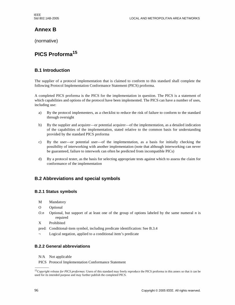
IEEEStd 802.1AB-2005 LOCAL AND METROPOLITAN AREA NETWORKS
Annex B
(normative)
PICS Proforma15
B.1 Introduction
The supplier of a protocol implementation that is claimed to conform to this standard shall complete thefollowing Protocol Implementation Conformance Statement (PICS) proforma.
A completed PICS proforma is the PICS for the implementation in question. The PICS is a statement ofwhich capabilities and options of the protocol have been implemented. The PICS can have a number of uses,including use:
a) By the protocol implementers, as a checklist to reduce the risk of failure to conform to the standardthrough oversight
b) By the supplier and acquirer—or potential acquirer—of the implementation, as a detailed indicationof the capabilities of the implementation, stated relative to the common basis for understandingprovided by the standard PICS proforma
c) By the user—or potential user—of the implementation, as a basis for initially checking thepossibility of interworking with another implementation (note that although interworking can neverbe guaranteed, failure to interwork can often be predicted from incompatible PICs)
d) By a protocol tester, as the basis for selecting appropriate tests against which to assess the claim forconformance of the implementation
B.2 Abbreviations and special symbols
B.2.1 Status symbols
M Mandatory
O Optional
O.n Optional, but support of at least one of the group of options labeled by the same numeral n isrequired
X Prohibited
pred: Conditional-item symbol, including predicate identification: See B.3.4
¬ Logical negation, applied to a conditional item’s predicate
B.2.2 General abbreviations
N/A Not applicable
PICS Protocol Implementation Conformance Statement
15Copyright release for PICS proformas: Users of this standard may freely reproduce the PICS proforma in this annex so that it can beused for its intended purpose and may further publish the completed PICS.
96 Copyright © 2005 IEEE. All rights reserved.

IEEESTATION AND MEDIA ACCESS CONTROL CONNECTIVITY DISCOVERY Std 802.1AB-2005
B.3 Instructions for completing the PICS proforma
B.3.1 General structure of the PICS proforma
The first part of the PICS proforma, implementation identification and protocol summary, is to be completedas indicated with the information necessary to identify fully both the supplier and the implementation.
The main part of the PICS proforma is a fixed-format questionnaire, divided into several subclauses, eachcontaining a number of individual items. Answers to the questionnaire items are to be provided in the right-most column, either by simply marking an answer to indicate a restricted choice (usually Yes or No), or byentering a value or a set or range of values. (Note that there are some items in which two or more choicesfrom a set of possible answers can apply; all relevant choices are to be marked.)
Each item is identified by an item reference in the first column. The second column contains the question tobe answered; the third column records the status of the item—whether support is mandatory, optional, orconditional; see also B.3.4. The fourth column contains the reference or references to the material thatspecifies the item in the main body of this standard, and the fifth column provides the space for the answers.
A supplier may also provide (or be required to provide) further information, categorized as either AdditionalInformation or Exception Information. When present, each kind of further information is to be provided in afurther subclause of items labeled Ai or Xi, respectively, for cross-referencing purposes, where i is anyunambiguous identification for the item (e.g., simply a numeral). There are no other restrictions on its formatand presentation.
A completed PICS proforma, including any Additional Information and Exception Information, is theProtocol Implementation Conformation Statement for the implementation in question.
NOTE—Where an implementation is capable of being configured in more than one way, a single PICS may be able todescribe all such configurations. However, the supplier has the choice of providing more than one PICS, each coveringsome subset of the implementation's configuration capabilities, in case that makes for easier and clearer presentation ofthe information.
B.3.2 Additional information
Items of Additional Information allow a supplier to provide further information intended to assist theinterpretation of the PICS. It is not intended or expected that a large quantity will be supplied, and a PICScan be considered complete without any such information. Examples might be an outline of the ways inwhich a (single) implementation can be set up to operate in a variety of environments and configurations, orinformation about aspects of the implementation that are outside the scope of this standard but that have abearing on the answers to some items.
References to items of Additional Information may be entered next to any answer in the questionnaire andmay be included in items of Exception Information.
B.3.3 Exception information
It may occasionally happen that a supplier will wish to answer an item with mandatory status (after anyconditions have been applied) in a way that conflicts with the indicated requirement. No preprinted answerwill be found in the Support column for this: instead, the supplier shall write the missing answer into theSupport column, together with an Xi reference to an item of Exception Information, and shall provide theappropriate rationale in the Exception item.
An implementation for which an Exception item is required in this way does not conform to this standard.
NOTE—A possible reason for the situation described above is that a defect in this standard has been reported, acorrection for which is expected to change the requirement not met by the implementation.
Copyright © 2005 IEEE. All rights reserved. 97

IEEEStd 802.1AB-2005 LOCAL AND METROPOLITAN AREA NETWORKS
B.3.4 Conditional status
B.3.4.1 Conditional items
The PICS proforma contains a number of conditional items. These are items for which both the applicabilityof the item itself, and its status if it does apply—mandatory or optional—are dependent upon whether or notcertain other items are supported.
Where a group of items is subject to the same condition for applicability, a separate preliminary questionabout the condition appears at the head of the group, with an instruction to skip to a later point in thequestionnaire if the “Not Applicable” answer is selected. Otherwise, individual conditional items areindicated by a conditional symbol in the Status column.
A conditional symbol is of the form “pred: S,” where pred is a predicate as described in B.3.4.2, and S is astatus symbol, M or 0.
If the value of the predicate is TRUE (see B.3.4.2), the conditional item is applicable, and its status isindicated by the status symbol following the predicate: the answer column is to be marked in the usual way.If the value of the predicate is FALSE, the “Not Applicable” (N/A)16 answer is to be marked.
B.3.4.2 Predicates
A predicate is one of the following:
a) An item-reference for an item in the PICS proforma: The value of the predicate is TRUE if the itemis marked as supported, and is FALSE otherwise.
b) A predicate-name, for a predicate defined as a boolean expression constructed by combiningitem-references using the boolean operator OR: The value of the predicate is TRUE if one or moreof the items is marked as supported.
c) A predicate-name, for a predicate defined as a boolean expression constructed by combiningitem-references using the boolean operator AND: The value of the predicate is TRUE if all of theitems are marked as supported.
d) The logical negation symbol “¬” prefixed to an item-reference or predicate-name: The value of thepredicate is TRUE if the value of the predicate formed by omitting the “¬” symbol is FALSE, andvice versa.
Each item whose reference is used in a predicate or predicate definition, or in a preliminary question forgrouped conditional items, is indicated by an asterisk17 in the Item column.
16(N/A) is currently not used in this PICs.17Asterisks are currently not used in this PICs.
98 Copyright © 2005 IEEE. All rights reserved.
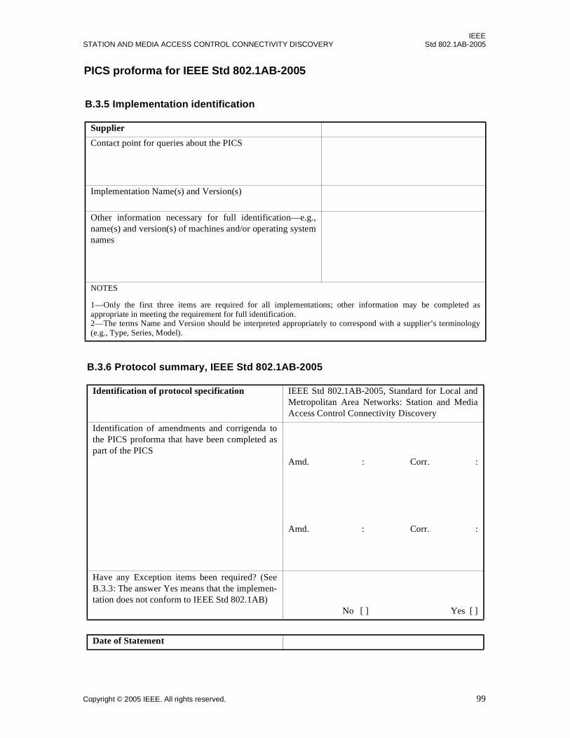
IEEESTATION AND MEDIA ACCESS CONTROL CONNECTIVITY DISCOVERY Std 802.1AB-2005
PICS proforma for IEEE Std 802.1AB-2005
B.3.5 Implementation identification
Supplier
Contact point for queries about the PICS
Implementation Name(s) and Version(s)
Other information necessary for full identification—e.g.,name(s) and version(s) of machines and/or operating systemnames
NOTES
1—Only the first three items are required for all implementations; other information may be completed asappropriate in meeting the requirement for full identification.2—The terms Name and Version should be interpreted appropriately to correspond with a supplier’s terminology(e.g., Type, Series, Model).
B.3.6 Protocol summary, IEEE Std 802.1AB-2005
Identification of protocol specification IEEE Std 802.1AB-2005, Standard for Local andMetropolitan Area Networks: Station and MediaAccess Control Connectivity Discovery
Identification of amendments and corrigenda tothe PICS proforma that have been completed aspart of the PICS
Amd. : Corr. :
Amd. : Corr. :
Have any Exception items been required? (SeeB.3.3: The answer Yes means that the implemen-tation does not conform to IEEE Std 802.1AB)
No [ ] Yes [ ]
Date of Statement
Copyright © 2005 IEEE. All rights reserved. 99
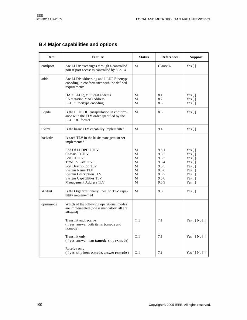
IEEEStd 802.1AB-2005 LOCAL AND METROPOLITAN AREA NETWORKS
B.4 Major capabilities and options
Item Feature Status References Support
cntrlport Are LLDP exchanges through a controlled port if port access is controlled by 802.1X
M Clause 6 Yes [ ]
addr Are LLDP addressing and LLDP Ethertype encoding in conformance with the defined requirements
DA = LLDP_Multicast address SA = station MAC address LLDP Ethertype encoding
M M M
8.18.2 8.3
Yes [ ] Yes [ ] Yes [ ]
lldpdu Is the LLDPDU encapsulation in conform-ance with the TLV order specified by the LLDPDU format
M 8.3 Yes [ ]
tlvfmt Is the basic TLV capability implemented M 9.4 Yes [ ]
basictlv Is each TLV in the basic management set implemented
End Of LLDPDU TLV Chassis ID TLV Port ID TLV Time To Live TLV Port Description TLV System Name TLV System Description TLV System Capabilities TLV Management Address TLV
M M M M M M M M M
9.5.1 9.5.2 9.5.3 9.5.4 9.5.5 9.5.6 9.5.7 9.5.8 9.5.9
Yes [ ] Yes [ ] Yes [ ] Yes [ ] Yes [ ] Yes [ ] Yes [ ] Yes [ ] Yes [ ]
xtlvfmt Is the Organizationally Specific TLV capa-bility implemented
M 9.6 Yes [ ]
oprmmode Which of the following operational modes are implemented (one is mandatory, all are allowed)
Transmit and receive (if yes, answer both items txmode and rxmode)
Transmit only (if yes, answer item txmode, skip rxmode)
Receive only (if yes, skip item txmode, answer rxmode )
O.1
O.1
O.1
7.1
7.1
7.1
Yes [ ] No [ ]
Yes [ ] No [ ]
Yes [ ] No [ ]
100 Copyright © 2005 IEEE. All rights reserved.
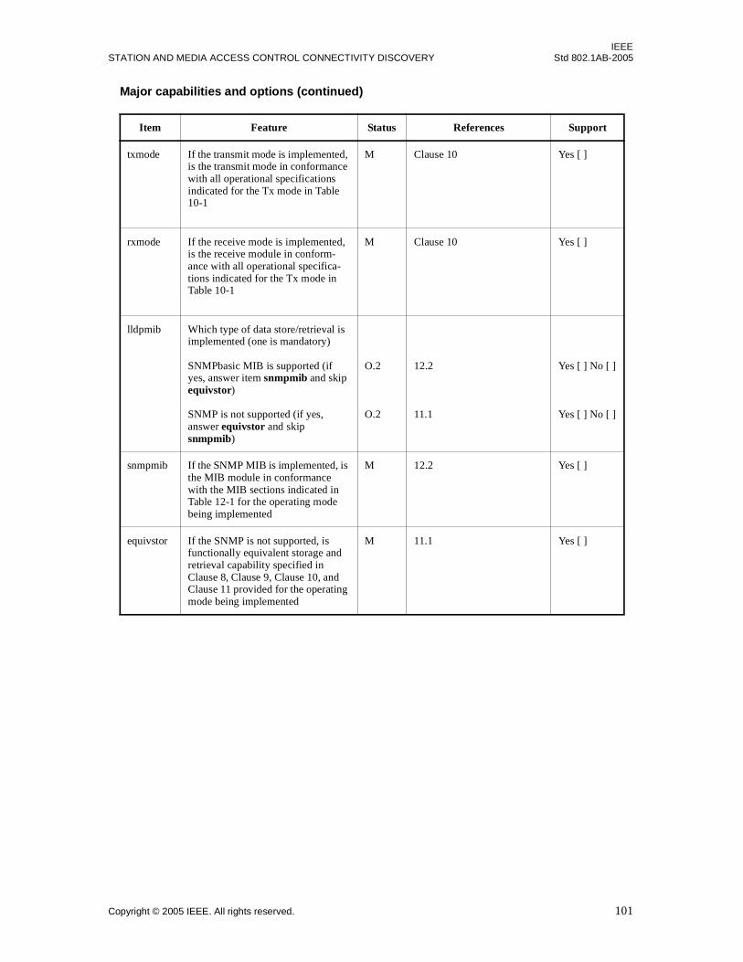
IEEESTATION AND MEDIA ACCESS CONTROL CONNECTIVITY DISCOVERY Std 802.1AB-2005
Major capabilities and options (continued)
Item Feature Status References Support
txmode If the transmit mode is implemented, is the transmit mode in conformance with all operational specifications indicated for the Tx mode in Table 10-1
M Clause 10 Yes [ ]
rxmode If the receive mode is implemented, is the receive module in conform-ance with all operational specifica-tions indicated for the Tx mode in Table 10-1
M Clause 10 Yes [ ]
lldpmib Which type of data store/retrieval is implemented (one is mandatory)
SNMPbasic MIB is supported (if yes, answer item snmpmib and skip equivstor)
SNMP is not supported (if yes, answer equivstor and skip snmpmib)
O.2
O.2
12.2
11.1
Yes [ ] No [ ]
Yes [ ] No [ ]
snmpmib If the SNMP MIB is implemented, is the MIB module in conformance with the MIB sections indicated in Table 12-1 for the operating mode being implemented
M 12.2 Yes [ ]
equivstor If the SNMP is not supported, is functionally equivalent storage and retrieval capability specified in Clause 8, Clause 9, Clause 10, and Clause 11 provided for the operating mode being implemented
M 11.1 Yes [ ]
Copyright © 2005 IEEE. All rights reserved. 101

IEEEStd 802.1AB-2005 LOCAL AND METROPOLITAN AREA NETWORKS
Annex C
(informative)
PTOPO MIB update
The PTOPO MIB should be updated according to the following rules:
a) If any objects in the LLDP remote systems MIB age out, the equivalent objects in the PTOPO MIBshould be deleted.
b) If the TTL value in the Time To Live TLV is zero, then the port is being shutdown and the PTOPOMIB objects associated with the MSAP identifier should be deleted.
c) If the TTL field is non-zero, then the appropriate ptopoRemEntry is found or created, based on thedata elements included in the LLDP frame. If the indicated entry is dynamic (i.e., ptopoConnIsStaticis FALSE), then the current sysUpTime value is stored in the ptopoConnLastVerifyTime field forthe entry.
d) If a ptopoRemEntry was added then the ptopoConnTabInserts counter is incremented.
e) If any ptopoRemEntry was added or deleted, or if information other than the ptopoRemLastVerify-Time changed for any entry due to the processing of this LLDP frame, the ptopoLastChangeTimeobject is set with the current sysUpTime, and a ptopoConfigChange trap event is generated. (See thePTOPO MIB for information on ptopoConfigChange trap generation.)
102 Copyright © 2005 IEEE. All rights reserved.

IEEESTATION AND MEDIA ACCESS CONTROL CONNECTIVITY DISCOVERY Std 802.1AB-2005
Annex D
(informative)
Example LLDP transmission frame formats
The LLDP MAC frame format is based on the particular transmission protocol. The following exampleformats illustrate the indicated LLDP Ethertype encoding method.
D.1 Direct-encoded LLDP frame format
The IEEE 802.3 LLDP frame format is shown in Figure D-1.
Figure D-1—IEEE 802.3 LLDP frame format
D.2 SNAP-encoded LLDP frame format
The Token Ring/FDDI LLDP frame format is shown in Figure D-2.
Figure D-2—Token Ring/FDDI LLDP frame format
LLDP_Multicastaddress
MACaddress LLDPDU
DA SA Ethertype Data + pad
FCS88-CC
LLDP
4 octets1500 octets2 octets6 octets6 octets
LLDP_Multicastaddress
MACaddress.
LLDPDU
NOTE---the maximum length for the LLDPDU is dependent on the maximum information field size for the transmission rate and protocol. (See 9.1)
FCS
SNAP-encoded LLDP Ethertype
DA SA Information field
AA-AA-03-00-00-00-88-CC
4 octetsSee note8 octets6 octets6 octets
Copyright © 2005 IEEE. All rights reserved. 103
IEEEStd 802.1AB-2005 LOCAL AND METROPOLITAN AREA NETWORKS
Annex E
(informative)
Using LLDP to detect potential communication problems
E.1 Overview
Some of the attributes exchanged via LLDP may be used to detect certain mis-configurations that mayimpair station communication. Under certain circumstances, while LLDPDU exchange is possible,communication between two stations may be impaired because of partial component failure or impropermanual configuration of local parameters. In these cases, analysis of the information exchanged withinLLDP may be used to detect potential communication or configuration problems and notify the localmanagement entity.
LLDP does not provide a means to resolve problems due to inconsistent configuration or component failure.These actions are clearly beyond the scope of this specification. LLDP does offer an advertisement ofinformation that can be used to detect a limited set of such problems. Whether a problem truly exists or notis also a question of local management policy and interpretation of the advertised information. In manycommon installations, the information exchanged in the following TLVs can indicate the associatedproblems.
E.2 IEEE 802.1 Organizationally Specific TLVs
E.2.1 Port VLAN ID TLV
While it is not strictly an error to have two systems configured with different port VLAN ID (PVID) valuesconnected to the same link, in practice it can represent a mis-configuration that is prohibiting twomanagement interfaces from talking with one another. In many deployments of IEEE 802.1Q, amanagement interface for a system is accessible by a management addresses that is associated with theVLAN the port has been configured on. The network addresses for two systems assumed to be on the sameVLAN can assume their addresses are on the same subnet, allowing direct communication. If the systemsare actually configured to be on different VLANs, but happen to be connected to a common link withdifferent views of what is the port VLAN on that link, communication problems between the managementstacks may exist. Since the PVID is a locally administered value it is possible that it may be configured to beany valid value, however, it is common practice to have the PVID of two systems connected to the same linkto be the same.
E.2.2 IEEE 802.1 Port and Protocol VLAN ID TLVs
The port and protocol VLAN IDs (PPVID) are untagged VLANs for a port, which when connected to a linkwith other port and protocol VLAN members, can have the same issues described with port VLAN IDs. Themanagement addresses used to access management objects should be mapped to the correct VIDs so aremote manager can properly access the system.
Port and protocol VLANs have the additional complication that specific classification rules are used to mapframes to the appropriate VLAN. In many cases these classification rules should be consistent betweensystems on the same link. The rules are represented in the IEEE 802.1Q management structures, but it wouldbe excessive and redundant to advertise these rules in LLDP. However, knowing the set of ports attached tothe link that are capable and enabled for port and protocol VLANs is valuable for detecting a possible mis-configuration. Ports that are using a management address reachable by a port and protocol VLAN may wishto have equivalent mapping rules for frames to VLANs. The IEEE 802.1Q MIB of each system enabled withport and protocol VLANs can be consulted to verify the mapping rules.
104 Copyright © 2005 IEEE. All rights reserved.

IEEESTATION AND MEDIA ACCESS CONTROL CONNECTIVITY DISCOVERY Std 802.1AB-2005
E.2.3 VLAN Name TLVs
The MIB of managed objects for bridges with VLAN extensions [RFC 2674] defines an object,dot1qVlanStaticName, which provides a name for a VLAN. Additionally, most VLAN bridgeimplementations provide some method for the network manager to administratively assign a name to aVLAN. While there is no requirement for the name of a VLAN on one bridge to be consistent with the nameof the same VLAN on another bridge, it is common practice that these names would be the same.
Network managers typically assign meaningful names to VLANs. For example, a VLAN with VID 10 mightbe called the ‘Management’ VLAN from which all bridges on the LAN can be accessed by a networkmanagement utility. A VLAN with VID 408 might be called the ‘Voice’ VLAN on which IP Telephonyequipment resides. Network managers might also assign names to VLANs that help indicate what subnetaddresses are used by stations on that VLAN. For example, a VLAN with VID 23 might be called‘192.168.254.0/24’. In any case, the network manager often uses the naming facility to provide meaningfuland consistent names for the VLANs.
In situations where VLAN names have been consistently applied throughout the LAN, the informationcarried in the VLAN Name TLV may be used to detect a mis-configuration. The VLAN Name TLVessentially provides the mapping of a VID to a VLAN name as assigned by the network manager. The sameVID with two different names will not prevent communication on the associated VLAN, however, thecommunication may not be what the network manager intended.
E.2.4 Protocol Identity TLVs
Protocols such as Spanning Tree Protocol, the Link Aggregation Control Protocol, and numerous vendorproprietary variations are responsible for maintaining the topology and connectivity of the network. Whilemany of these protocols have mechanisms built into them that allow interpretability with older versions,different variations or alternate modes of operation, it is possible for some of these protocols to interactimproperly with one another causing breaks in the topology or interruptions in an otherwise connectednetwork.
The Protocol Identity TLV provides a way for stations to advertise protocols that are important to theoperation of the network. A management entity may be able to diagnose connectivity issues byunderstanding the set of topology management protocols operating on peer network devices. Stations mayalso be able to discover peer protocol agents that operate a preferred version of a proprietary protocol andtherefore eliminate the need to develop or execute multiple independent protocol discovery mechanisms.
E.3 IEEE 802.3 Organizationally Specific TLVs
E.3.1 MAC/PHY Configuration/Status TLV
It is possible for two ends of an IEEE 802.3 link to be configured with different duplex and/or speed settingsand still establish some limited network connectivity. For example:
a) In IEEE 802.3 copper links, auto-negotiation can be overridden by manual configuration and maycause the link configuration to converge in an undesirable way. The auto-negotiation supported andauto-negotiation status fields of the auto-negotiation TLVs passed between two systems attached tothe same link should indicate the same settings:
1) If auto-negotiation is supported and enabled in both systems, there should be not duplex orspeed differences. The current speed and duplex settings can be determined by comparing the802.3 PMD supported functionality field settings to determine highest common denominatorlevel as defined in IEEE Std 802.3-2002, Annex 28 B.3
Copyright © 2005 IEEE. All rights reserved. 105
IEEEStd 802.1AB-2005 LOCAL AND METROPOLITAN AREA NETWORKS
2) If the received TLV indicates that auto-negotiation is supported but not enabled, the currentduplex and speed settings of the sending system will be defined by the operational MAU typefield in that TLV. These can be compared with the speed and duplex settings in the receivingsystem to determine whether there is a mismatch.
b) In fiber links supporting data rates less than 10 Gbits/second, full duplex IEEE 802.3 MAC/PHYscan also support half duplex operation:
1) The duplex configuration can not be auto-configured in full duplex MAC/PHYs and must beset by network management.
2) A received TLV with an operational MAU type that is different from the local system’soperational MAU type can indicate the potential for frame loss.
E.3.2 Link Aggregation TLV
It is possible for one system to believe it has formed a link aggregation with a remote port while the othersystem is unaware of the aggregation. This type of configuration may cause network loops or unpredictablecommunication depending upon the distribution algorithm used to load balance traffic. This situation canoccur with manual configuration of the link aggregation and the setting the LACP protocol to passive onboth sides. It may also occur if manual link aggregations have been established by implementations that arenot using the LACP protocol (while this approach is non-standard, it is in wide use today).
The Link Aggregation TLV informs the remote port whether or not the sending port believes it is currentlyin a link aggregation. It also provides Port ID information for the aggregated port so a management stationcan efficiently access the link aggregation management objects.
E.3.3 Power Via MDI TLV
An incompatibility of power classes may exist when there is a configuration inconsistency between thepower sourcing equipment (PSE) and the powered device (PD). For example, if the PSE port suppliesClass_2 (7.0 watts) and advertises it, but the PD port is class_0 (0.44 to 19.95 watts) and requires higherpower (more than 7.0 watts) in some modes, connectivity problems may result.
E.3.4 Maximum Frame Size TLV
Differences in maximum frame size can result in loss of frames if a sending station transmits frames largerthan the advertised maximum frame size supported by the receiving station. The Maximum Frame Size TLVcan be used to detect mis-configurations or incompatibility between two stations with different maximumsupported frame sizes.
106 Copyright © 2005 IEEE. All rights reserved.
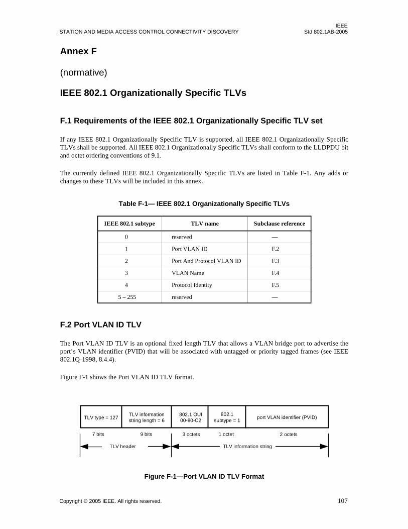
IEEESTATION AND MEDIA ACCESS CONTROL CONNECTIVITY DISCOVERY Std 802.1AB-2005
Annex F
(normative)
IEEE 802.1 Organizationally Specific TLVs
F.1 Requirements of the IEEE 802.1 Organizationally Specific TLV set
If any IEEE 802.1 Organizationally Specific TLV is supported, all IEEE 802.1 Organizationally SpecificTLVs shall be supported. All IEEE 802.1 Organizationally Specific TLVs shall conform to the LLDPDU bitand octet ordering conventions of 9.1.
The currently defined IEEE 802.1 Organizationally Specific TLVs are listed in Table F-1. Any adds orchanges to these TLVs will be included in this annex.
F.2 Port VLAN ID TLV
The Port VLAN ID TLV is an optional fixed length TLV that allows a VLAN bridge port to advertise theport’s VLAN identifier (PVID) that will be associated with untagged or priority tagged frames (see IEEE802.1Q-1998, 8.4.4).
Figure F-1 shows the Port VLAN ID TLV format.
Figure F-1—Port VLAN ID TLV Format
Table F-1— IEEE 802.1 Organizationally Specific TLVs
IEEE 802.1 subtype TLV name Subclause reference
0 reserved —
1 Port VLAN ID F.2
2 Port And Protocol VLAN ID F.3
3 VLAN Name F.4
4 Protocol Identity F.5
5 – 255 reserved —
TLV header
TLV type = 127TLV informationstring length = 6
port VLAN identifier (PVID)802.1
subtype = 1
9 bits7 bits 1 octet 2 octets3 octets
TLV information string
802.1 OUI00-80-C2
Copyright © 2005 IEEE. All rights reserved. 107
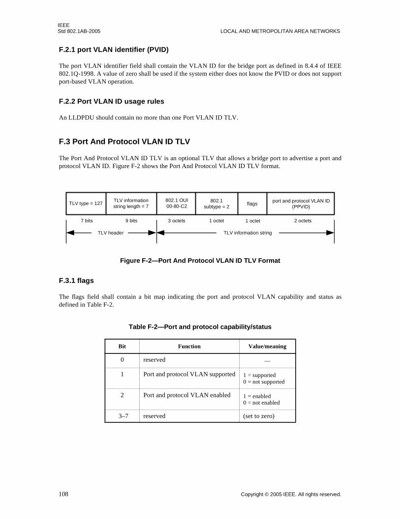
IEEEStd 802.1AB-2005 LOCAL AND METROPOLITAN AREA NETWORKS
F.2.1 port VLAN identifier (PVID)
The port VLAN identifier field shall contain the VLAN ID for the bridge port as defined in 8.4.4 of IEEE802.1Q-1998. A value of zero shall be used if the system either does not know the PVID or does not supportport-based VLAN operation.
F.2.2 Port VLAN ID usage rules
An LLDPDU should contain no more than one Port VLAN ID TLV.
F.3 Port And Protocol VLAN ID TLV
The Port And Protocol VLAN ID TLV is an optional TLV that allows a bridge port to advertise a port andprotocol VLAN ID. Figure F-2 shows the Port And Protocol VLAN ID TLV format.
Figure F-2—Port And Protocol VLAN ID TLV Format
F.3.1 flags
The flags field shall contain a bit map indicating the port and protocol VLAN capability and status asdefined in Table F-2.
Table F-2—Port and protocol capability/status
Bit Function Value/meaning
0 reserved —
1 Port and protocol VLAN supported 1 = supported0 = not supported
2 Port and protocol VLAN enabled 1 = enabled0 = not enabled
3–7 reserved (set to zero)
2 octets
flags
1 octet
TLV header
TLV type = 127TLV informationstring length = 7
802.1subtype = 2
9 bits7 bits 1 octet
port and protocol VLAN ID(PPVID)
3 octets
TLV information string
802.1 OUI00-80-C2
108 Copyright © 2005 IEEE. All rights reserved.
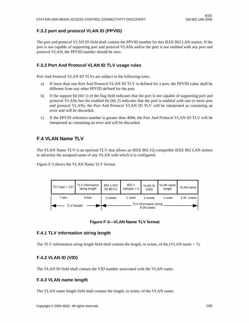
IEEESTATION AND MEDIA ACCESS CONTROL CONNECTIVITY DISCOVERY Std 802.1AB-2005
F.3.2 port and protocol VLAN ID (PPVID)
The port and protocol VLAN ID field shall contain the PPVID number for this IEEE 802 LAN station. If theport is not capable of supporting port and protocol VLANs and/or the port is not enabled with any port andprotocol VLAN, the PPVID number should be zero.
F.3.3 Port And Protocol VLAN ID TLV usage rules
Port And Protocol VLAN ID TLVs are subject to the following rules:
a) If more than one Port And Protocol VLAN ID TLV is defined for a port, the PPVID value shall bedifferent from any other PPVID defined for the port.
b) If the support bit (bit 1) of the flag field indicates that the port is not capable of supporting port andprotocol VLANs but the enabled bit (bit 2) indicates that the port is enabled with one or more portand protocol VLANs, the Port And Protocol VLAN ID TLV will be interpreted as containing anerror and will be discarded.
c) If the PPVID reference number is greater than 4094, the Port And Protocol VLAN ID TLV will beinterpreted as containing an error and will be discarded.
F.4 VLAN Name TLV
The VLAN Name TLV is an optional TLV that allows an IEEE 802.1Q-compatible IEEE 802 LAN stationto advertise the assigned name of any VLAN with which it is configured.
Figure F-3 shows the VLAN Name TLV format.
Figure F-3—VLAN Name TLV format
F.4.1 TLV information string length
The TLV information string length field shall contain the length, in octets, of the (VLAN name + 7).
F.4.2 VLAN ID (VID)
The VLAN ID field shall contain the VID number associated with the VLAN name.
F.4.3 VLAN name length
The VLAN name length field shall contain the length, in octets, of the VLAN name.
TLV header
TLV type = 127TLV information
string length VLAN name802.1
subtype = 3
9 bits7 bits 1 octet 1-32 octets3 octets
TLV information string8-39 octets
VLAN ID(VID)
1 octet2 octets
VLAN namelength
802.1 OUI00-80-C2
Copyright © 2005 IEEE. All rights reserved. 109
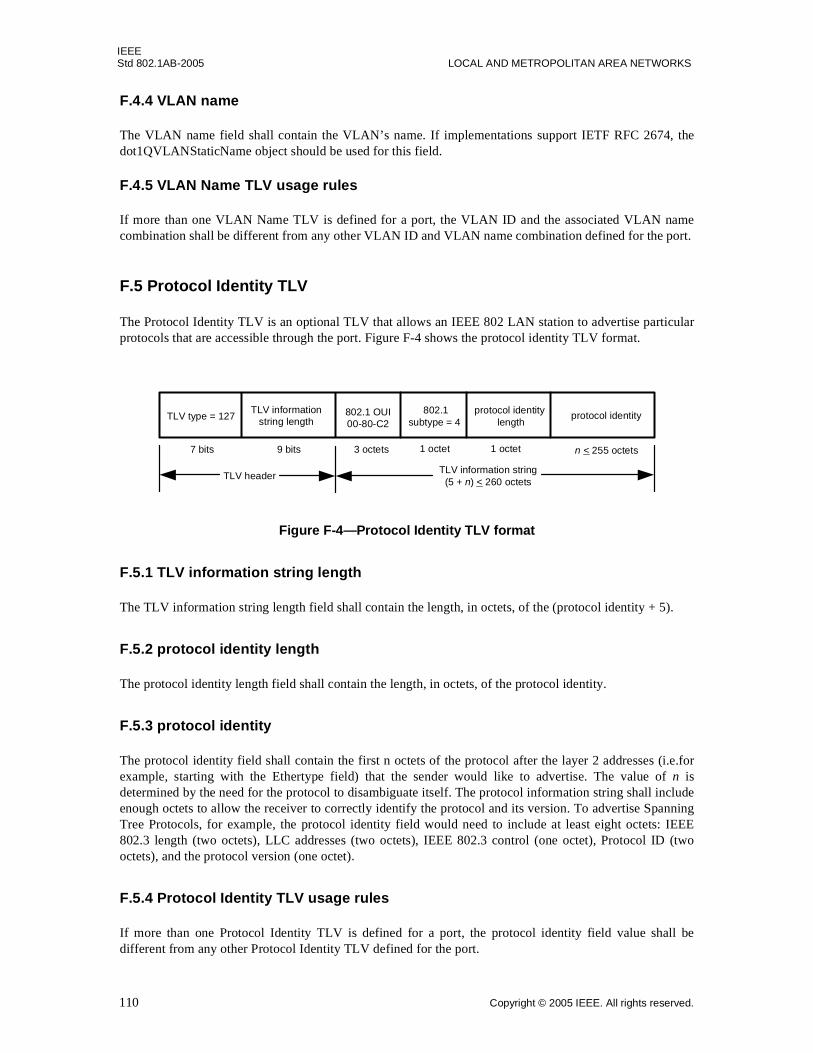
IEEEStd 802.1AB-2005 LOCAL AND METROPOLITAN AREA NETWORKS
F.4.4 VLAN name
The VLAN name field shall contain the VLAN’s name. If implementations support IETF RFC 2674, thedot1QVLANStaticName object should be used for this field.
F.4.5 VLAN Name TLV usage rules
If more than one VLAN Name TLV is defined for a port, the VLAN ID and the associated VLAN namecombination shall be different from any other VLAN ID and VLAN name combination defined for the port.
F.5 Protocol Identity TLV
The Protocol Identity TLV is an optional TLV that allows an IEEE 802 LAN station to advertise particularprotocols that are accessible through the port. Figure F-4 shows the protocol identity TLV format.
Figure F-4—Protocol Identity TLV format
F.5.1 TLV information string length
The TLV information string length field shall contain the length, in octets, of the (protocol identity + 5).
F.5.2 protocol identity length
The protocol identity length field shall contain the length, in octets, of the protocol identity.
F.5.3 protocol identity
The protocol identity field shall contain the first n octets of the protocol after the layer 2 addresses (i.e.forexample, starting with the Ethertype field) that the sender would like to advertise. The value of n isdetermined by the need for the protocol to disambiguate itself. The protocol information string shall includeenough octets to allow the receiver to correctly identify the protocol and its version. To advertise SpanningTree Protocols, for example, the protocol identity field would need to include at least eight octets: IEEE802.3 length (two octets), LLC addresses (two octets), IEEE 802.3 control (one octet), Protocol ID (twooctets), and the protocol version (one octet).
F.5.4 Protocol Identity TLV usage rules
If more than one Protocol Identity TLV is defined for a port, the protocol identity field value shall bedifferent from any other Protocol Identity TLV defined for the port.
TLV header
TLV type = 127TLV information
string lengthprotocol identity 802.1
subtype = 4
3 octets n < 255 octets1 octet7 bits 9 bits
TLV information string(5 + n) < 260 octets
protocol identity length
1 octet
802.1 OUI00-80-C2
110 Copyright © 2005 IEEE. All rights reserved.
IEEESTATION AND MEDIA ACCESS CONTROL CONNECTIVITY DISCOVERY Std 802.1AB-2005
F.6 IEEE 802.1 Organizationally Specific TLV management
F.6.1 IEEE 802.1 Organizationally Specific TLV selection management
TLV selection management consists of providing the network manager with the means to select whichspecific IEEE 802.1 Organizationally Specific TLVs are enabled for inclusion in an LLDPDU. Thefollowing LLDP variables cross reference to LLDP local systems configuration MIB tables indicate whichspecific TLVs are enabled for the particular port(s) on the system. The specific port(s) through which eachTLV is enabled for transmission may be set (or reset) by the network manager:
a) mibXdot1PortVlanTxEnable: This variable lists the VLAN ID of the port through which thereferenced TLV is enabled for transmission.
b) mibXdot1VlanNameConfigTxEnable: This variable lists the different VLAN name/PPVID TLVsthat are defined for the system, each with a bit map indicating the system ports through which theparticular VLAN name TLV is enabled for transmission.
c) mibXdot1ProtoVlanConfigTxEnable: This variable lists the port and protocol VLAN TLVs thatare defined for the system, each with a bit map indicating the system ports through which theparticular port and protocol VLAN TLV is enabled for transmission.
d) mibXdot1ProtocolConfigTxEnable: This variable lists the protocol identity TLVs that are definedfor the system, each with a bit map indicating the system ports through which the particular protocolTLV is enabled for transmission.
F.6.2 IEEE 802.1 managed objects—TLV variables
F.6.2.1 Port VLAN ID TLV managed objects
a) PVID: The port VLAN identifier (see F.2.1).
F.6.2.2 Port And Protocol VLAN ID TLV managed objects
a) Port and protocol VLAN supported: A flag indicating whether port and protocol VLANs aresupported (see F.3.1).
b) Port and protocol VLAN enabled: A flag indicating whether port and protocol VLANs areenabled (see F.3.1).
c) PPVID: The advertised port and protocol VLAN ID (see F.3.2).
F.6.2.3 VLAN Name TLV managed objects
a) VID: The VLAN ID associated with the VLAN name (see F.4.2).
b) VLAN name length: The length of the VLAN name (see F.4.3).
c) VLAN name: The VLAN’s name (see F.4.4).
F.6.2.4 Protocol Identity TLV managed objects
a) protocol identity length: The length of the protocol identity (see F.5.2).
b) protocol identity: The protocol’s identity (see F.5.3).
F.6.3 IEEE 802.1 Organizationally Specific TLV variable/MIB object cross reference
Table F-3 lists the relationship both between 802.3 TLV selection variables and their corresponding LLDPCONFIG objects.
Copyright © 2005 IEEE. All rights reserved. 111

IEEEStd 802.1AB-2005 LOCAL AND METROPOLITAN AREA NETWORKS
F.6.4 IEEE 802.1 Organizationally Specific TLV/MIB object cross references
The cross references between the IEEE 802.1 Organizationally Specific TLVs and the LLDP local systemMIB objects are listed in Table F-4.
The cross references between the IEEE 802.1 Organizationally Specific TLVs and the LLDP remotesystems MIB objects are listed in Table F-5.
Table F-3—802.1 Organizationally Specific TLV selection variable/LLDP MIB object cross reference
802.1 TLV selection variable LLDP 802.1 MIB extension object
mibXdot1PortVlanTLVTxEnable lldpXdot1configPortVlanTxEnable
mibXdot1VlanNameTLVsTxEnable mibXdot1ConfigVlanNameTxEnable
mibXdot1ProtoVlanTLVsTxEnable mibXdot1ConfigProtoVlanTxEnable
mibXdot1ProtocolTLVsTxEnable mibXdot1ConfigProtocolTxEnable
Table F-4—IEEE 802.1 Organizationally Specific TLV/local system MIB cross references
TLV name TLV variable LLDP local system MIB Object
Port VLAN ID PVID lldpXdot1LocPortVlanId
Port And Protocol VLAN ID port and protocol VLAN supported lldpXdot1LocProtoVlanSupported
port and protocol VLAN enabled lldpXdot1LocProtoVlanEnabled
PPVID lldpXdot1LocProtoVlanId
VLAN Name VID lldpXdot1LocVlanId
VLAN name length lldpXdot1LocVlanName
VLAN name lldpXdot1LocVlanName
Protocol Identity protocol identity length lldpXdot1LocProtoId
protocol identity lldpXdot1LocProtoId
112 Copyright © 2005 IEEE. All rights reserved.
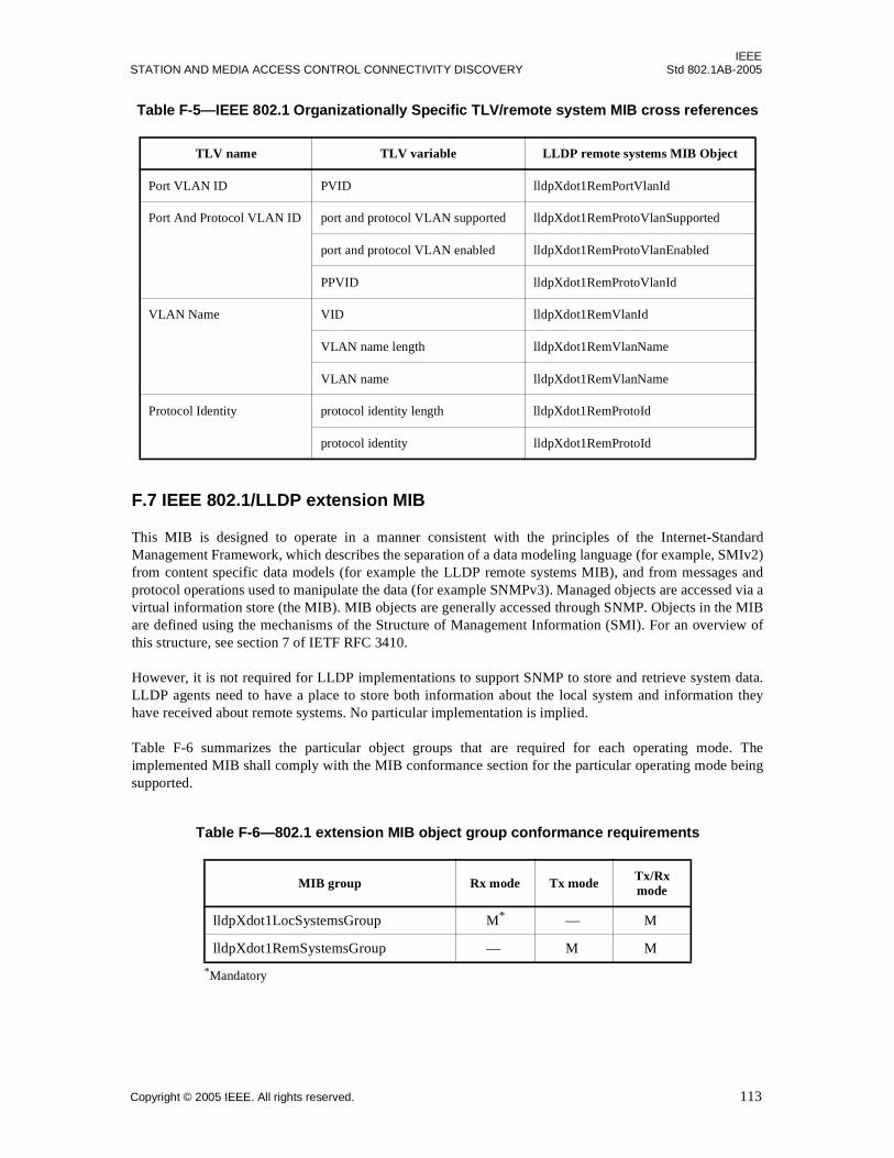
IEEESTATION AND MEDIA ACCESS CONTROL CONNECTIVITY DISCOVERY Std 802.1AB-2005
F.7 IEEE 802.1/LLDP extension MIB
This MIB is designed to operate in a manner consistent with the principles of the Internet-StandardManagement Framework, which describes the separation of a data modeling language (for example, SMIv2)from content specific data models (for example the LLDP remote systems MIB), and from messages andprotocol operations used to manipulate the data (for example SNMPv3). Managed objects are accessed via avirtual information store (the MIB). MIB objects are generally accessed through SNMP. Objects in the MIBare defined using the mechanisms of the Structure of Management Information (SMI). For an overview ofthis structure, see section 7 of IETF RFC 3410.
However, it is not required for LLDP implementations to support SNMP to store and retrieve system data.LLDP agents need to have a place to store both information about the local system and information theyhave received about remote systems. No particular implementation is implied.
Table F-6 summarizes the particular object groups that are required for each operating mode. Theimplemented MIB shall comply with the MIB conformance section for the particular operating mode beingsupported.
Table F-5—IEEE 802.1 Organizationally Specific TLV/remote system MIB cross references
TLV name TLV variable LLDP remote systems MIB Object
Port VLAN ID PVID lldpXdot1RemPortVlanId
Port And Protocol VLAN ID port and protocol VLAN supported lldpXdot1RemProtoVlanSupported
port and protocol VLAN enabled lldpXdot1RemProtoVlanEnabled
PPVID lldpXdot1RemProtoVlanId
VLAN Name VID lldpXdot1RemVlanId
VLAN name length lldpXdot1RemVlanName
VLAN name lldpXdot1RemVlanName
Protocol Identity protocol identity length lldpXdot1RemProtoId
protocol identity lldpXdot1RemProtoId
Table F-6—802.1 extension MIB object group conformance requirements
MIB group Rx mode Tx mode Tx/Rx mode
lldpXdot1LocSystemsGroup M*
*Mandatory
— M
lldpXdot1RemSystemsGroup — M M
Copyright © 2005 IEEE. All rights reserved. 113

IEEEStd 802.1AB-2005 LOCAL AND METROPOLITAN AREA NETWORKS
F.7.1 IEEE 802.1 LLDP extension MIB module 18,19
In the following MIB definition, should any discrepancy between the DESCRIPTION text and thecorresponding definition in F.2, F.3, F.4, and F.5 of this annex occur, the definition in F.2, F.3, F.4, and F.5shall take precedence.
LLDP-EXT-DOT1-MIB DEFINITIONS ::= BEGIN
IMPORTS MODULE-IDENTITY, OBJECT-TYPE, Integer32 FROM SNMPv2-SMI TruthValue FROM SNMPv2-TC SnmpAdminString FROM SNMP-FRAMEWORK-MIB MODULE-COMPLIANCE, OBJECT-GROUP FROM SNMPv2-CONF lldpExtensions, lldpLocPortNum, lldpRemTimeMark, lldpRemLocalPortNum, lldpRemIndex, lldpPortConfigEntry FROM LLDP-MIB VlanId FROM Q-BRIDGE-MIB;
lldpXdot1MIB MODULE-IDENTITY LAST-UPDATED "200505060000Z" -- May 06, 2005 ORGANIZATION "IEEE 802.1 Working Group" CONTACT-INFO " WG-URL: http://grouper.ieee.org/groups/802/1/index.html WG-EMail: [email protected]
Contact: Paul Congdon Postal: Hewlett-Packard Company 8000 Foothills Blvd. Roseville, CA 95747 USA Tel: +1-916-785-5753 E-mail: [email protected]" DESCRIPTION "The LLDP Management Information Base extension module for IEEE 802.1 organizationally defined discovery information.
In order to assure the uniqueness of the LLDP-MIB, lldpXdot1MIB is branched from lldpExtensions using OUI value as the node. An OUI/'company_id' is a 24 bit globally unique assigned number referenced by various standards.
Copyright (C) IEEE (2005). This version of this MIB module is published as Annex F.7.1 of IEEE Std 802.1AB-2005; see the standard itself for full legal notices." REVISION "200505060000Z" -- May 06, 2005 DESCRIPTION "Published as part of IEEE Std 802.1AB-2005 initial version."-- OUI for IEEE 802.1 is 32962 (00-80-C2)
18Copyright release for MIBs: Users of this standard may freely reproduce the MIB contained in this subclause so that it can be used forits intended purpose. 19An ASCII version of this MIB module can be obtained by Web browser from the IEEE 802.1 Website at http://www.ieee802.org/1/pages/MIBS.html.
114 Copyright © 2005 IEEE. All rights reserved.
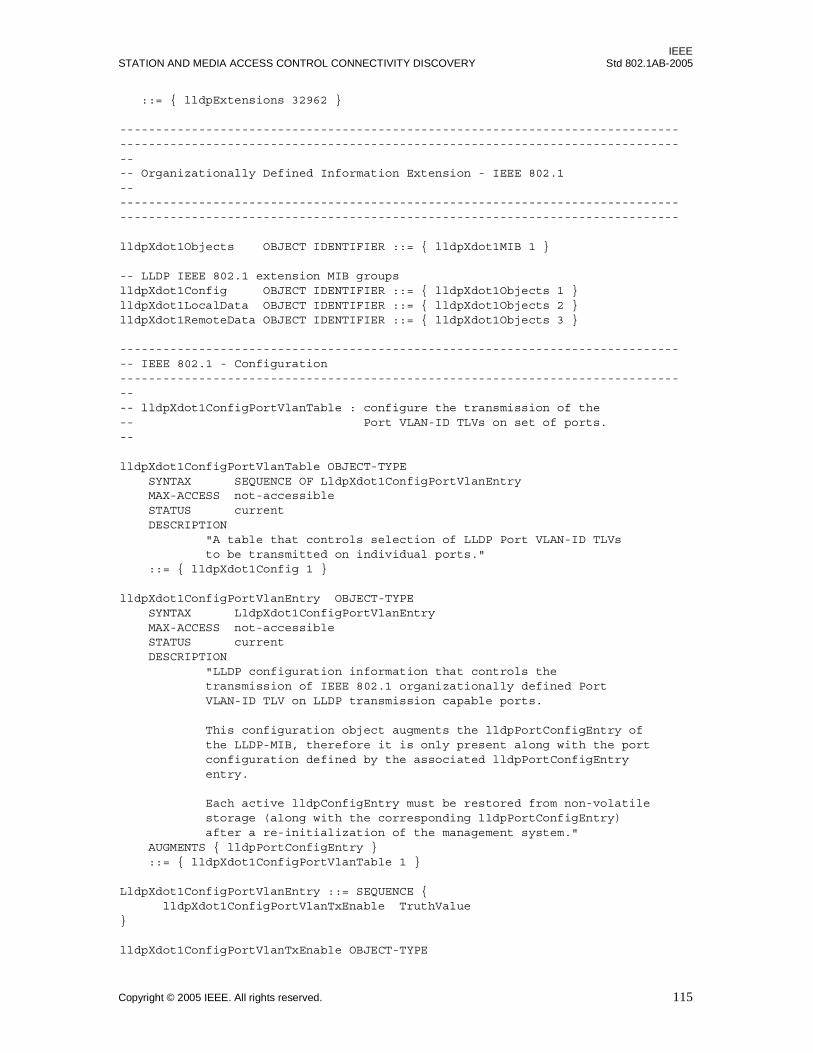
IEEESTATION AND MEDIA ACCESS CONTROL CONNECTIVITY DISCOVERY Std 802.1AB-2005
::= { lldpExtensions 32962 }
---------------------------------------------------------------------------------------------------------------------------------------------------------------- Organizationally Defined Information Extension - IEEE 802.1--------------------------------------------------------------------------------------------------------------------------------------------------------------
lldpXdot1Objects OBJECT IDENTIFIER ::= { lldpXdot1MIB 1 }
-- LLDP IEEE 802.1 extension MIB groupslldpXdot1Config OBJECT IDENTIFIER ::= { lldpXdot1Objects 1 }lldpXdot1LocalData OBJECT IDENTIFIER ::= { lldpXdot1Objects 2 }lldpXdot1RemoteData OBJECT IDENTIFIER ::= { lldpXdot1Objects 3 }
-------------------------------------------------------------------------------- IEEE 802.1 - Configuration---------------------------------------------------------------------------------- lldpXdot1ConfigPortVlanTable : configure the transmission of the -- Port VLAN-ID TLVs on set of ports.--
lldpXdot1ConfigPortVlanTable OBJECT-TYPE SYNTAX SEQUENCE OF LldpXdot1ConfigPortVlanEntry MAX-ACCESS not-accessible STATUS current DESCRIPTION "A table that controls selection of LLDP Port VLAN-ID TLVs to be transmitted on individual ports." ::= { lldpXdot1Config 1 }
lldpXdot1ConfigPortVlanEntry OBJECT-TYPE SYNTAX LldpXdot1ConfigPortVlanEntry MAX-ACCESS not-accessible STATUS current DESCRIPTION "LLDP configuration information that controls the transmission of IEEE 802.1 organizationally defined Port VLAN-ID TLV on LLDP transmission capable ports.
This configuration object augments the lldpPortConfigEntry of the LLDP-MIB, therefore it is only present along with the port configuration defined by the associated lldpPortConfigEntry entry.
Each active lldpConfigEntry must be restored from non-volatile storage (along with the corresponding lldpPortConfigEntry) after a re-initialization of the management system." AUGMENTS { lldpPortConfigEntry } ::= { lldpXdot1ConfigPortVlanTable 1 }
LldpXdot1ConfigPortVlanEntry ::= SEQUENCE { lldpXdot1ConfigPortVlanTxEnable TruthValue}
lldpXdot1ConfigPortVlanTxEnable OBJECT-TYPE
Copyright © 2005 IEEE. All rights reserved. 115
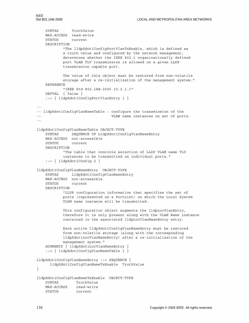
IEEEStd 802.1AB-2005 LOCAL AND METROPOLITAN AREA NETWORKS
SYNTAX TruthValue MAX-ACCESS read-write STATUS current DESCRIPTION "The lldpXdot1ConfigPortVlanTxEnable, which is defined as a truth value and configured by the network management, determines whether the IEEE 802.1 organizationally defined port VLAN TLV transmission is allowed on a given LLDP transmission capable port.
The value of this object must be restored from non-volatile storage after a re-initialization of the management system." REFERENCE "IEEE Std 802.1AB-2005 10.2.1.1" DEFVAL { false } ::= { lldpXdot1ConfigPortVlanEntry 1 }
---- lldpXdot1ConfigVlanNameTable : configure the transmission of the -- VLAN name instances on set of ports.--
lldpXdot1ConfigVlanNameTable OBJECT-TYPE SYNTAX SEQUENCE OF LldpXdot1ConfigVlanNameEntry MAX-ACCESS not-accessible STATUS current DESCRIPTION "The table that controls selection of LLDP VLAN name TLV instances to be transmitted on individual ports." ::= { lldpXdot1Config 2 }
lldpXdot1ConfigVlanNameEntry OBJECT-TYPE SYNTAX LldpXdot1ConfigVlanNameEntry MAX-ACCESS not-accessible STATUS current DESCRIPTION "LLDP configuration information that specifies the set of ports (represented as a PortList) on which the Local System VLAN name instance will be transmitted.
This configuration object augments the lldpLocVlanEntry, therefore it is only present along with the VLAN Name instance contained in the associated lldpLocVlanNameEntry entry.
Each active lldpXdot1ConfigVlanNameEntry must be restored from non-volatile storage (along with the corresponding lldpXdot1LocVlanNameEntry) after a re-initialization of the management system." AUGMENTS { lldpXdot1LocVlanNameEntry } ::= { lldpXdot1ConfigVlanNameTable 1 }
LldpXdot1ConfigVlanNameEntry ::= SEQUENCE { lldpXdot1ConfigVlanNameTxEnable TruthValue }
lldpXdot1ConfigVlanNameTxEnable OBJECT-TYPE SYNTAX TruthValue MAX-ACCESS read-write STATUS current
116 Copyright © 2005 IEEE. All rights reserved.
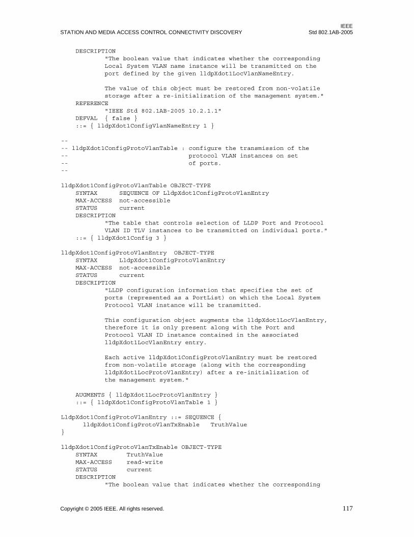
IEEESTATION AND MEDIA ACCESS CONTROL CONNECTIVITY DISCOVERY Std 802.1AB-2005
DESCRIPTION "The boolean value that indicates whether the corresponding Local System VLAN name instance will be transmitted on the port defined by the given lldpXdot1LocVlanNameEntry.
The value of this object must be restored from non-volatile storage after a re-initialization of the management system." REFERENCE "IEEE Std 802.1AB-2005 10.2.1.1" DEFVAL { false } ::= { lldpXdot1ConfigVlanNameEntry 1 }
---- lldpXdot1ConfigProtoVlanTable : configure the transmission of the -- protocol VLAN instances on set-- of ports.--
lldpXdot1ConfigProtoVlanTable OBJECT-TYPE SYNTAX SEQUENCE OF LldpXdot1ConfigProtoVlanEntry MAX-ACCESS not-accessible STATUS current DESCRIPTION "The table that controls selection of LLDP Port and Protocol VLAN ID TLV instances to be transmitted on individual ports." ::= { lldpXdot1Config 3 }
lldpXdot1ConfigProtoVlanEntry OBJECT-TYPE SYNTAX LldpXdot1ConfigProtoVlanEntry MAX-ACCESS not-accessible STATUS current DESCRIPTION "LLDP configuration information that specifies the set of ports (represented as a PortList) on which the Local System Protocol VLAN instance will be transmitted.
This configuration object augments the lldpXdot1LocVlanEntry, therefore it is only present along with the Port and Protocol VLAN ID instance contained in the associated lldpXdot1LocVlanEntry entry.
Each active lldpXdot1ConfigProtoVlanEntry must be restored from non-volatile storage (along with the corresponding lldpXdot1LocProtoVlanEntry) after a re-initialization of the management system."
AUGMENTS { lldpXdot1LocProtoVlanEntry } ::= { lldpXdot1ConfigProtoVlanTable 1 }
LldpXdot1ConfigProtoVlanEntry ::= SEQUENCE { lldpXdot1ConfigProtoVlanTxEnable TruthValue}
lldpXdot1ConfigProtoVlanTxEnable OBJECT-TYPE SYNTAX TruthValue MAX-ACCESS read-write STATUS current DESCRIPTION "The boolean value that indicates whether the corresponding
Copyright © 2005 IEEE. All rights reserved. 117
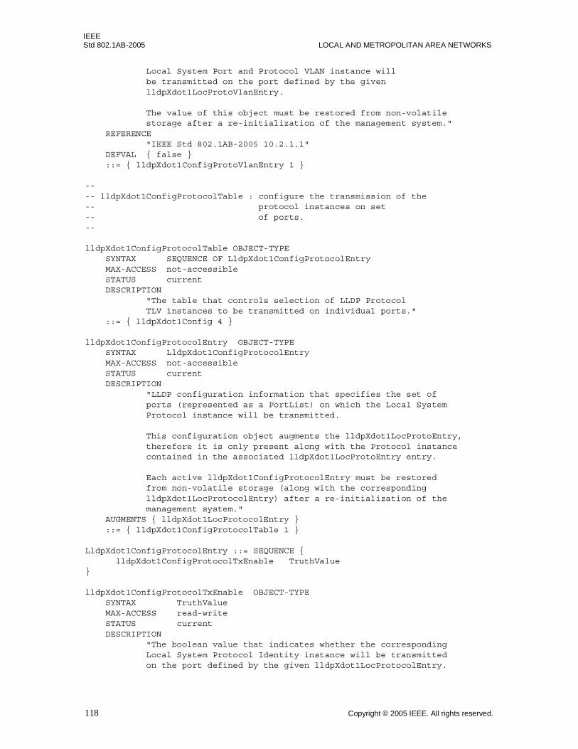
IEEEStd 802.1AB-2005 LOCAL AND METROPOLITAN AREA NETWORKS
Local System Port and Protocol VLAN instance will be transmitted on the port defined by the given lldpXdot1LocProtoVlanEntry.
The value of this object must be restored from non-volatile storage after a re-initialization of the management system." REFERENCE "IEEE Std 802.1AB-2005 10.2.1.1" DEFVAL { false } ::= { lldpXdot1ConfigProtoVlanEntry 1 }
---- lldpXdot1ConfigProtocolTable : configure the transmission of the -- protocol instances on set-- of ports.--
lldpXdot1ConfigProtocolTable OBJECT-TYPE SYNTAX SEQUENCE OF LldpXdot1ConfigProtocolEntry MAX-ACCESS not-accessible STATUS current DESCRIPTION "The table that controls selection of LLDP Protocol TLV instances to be transmitted on individual ports." ::= { lldpXdot1Config 4 }
lldpXdot1ConfigProtocolEntry OBJECT-TYPE SYNTAX LldpXdot1ConfigProtocolEntry MAX-ACCESS not-accessible STATUS current DESCRIPTION "LLDP configuration information that specifies the set of ports (represented as a PortList) on which the Local System Protocol instance will be transmitted.
This configuration object augments the lldpXdot1LocProtoEntry, therefore it is only present along with the Protocol instance contained in the associated lldpXdot1LocProtoEntry entry.
Each active lldpXdot1ConfigProtocolEntry must be restored from non-volatile storage (along with the corresponding lldpXdot1LocProtocolEntry) after a re-initialization of the management system." AUGMENTS { lldpXdot1LocProtocolEntry } ::= { lldpXdot1ConfigProtocolTable 1 }
LldpXdot1ConfigProtocolEntry ::= SEQUENCE { lldpXdot1ConfigProtocolTxEnable TruthValue}
lldpXdot1ConfigProtocolTxEnable OBJECT-TYPE SYNTAX TruthValue MAX-ACCESS read-write STATUS current DESCRIPTION "The boolean value that indicates whether the corresponding Local System Protocol Identity instance will be transmitted on the port defined by the given lldpXdot1LocProtocolEntry.
118 Copyright © 2005 IEEE. All rights reserved.
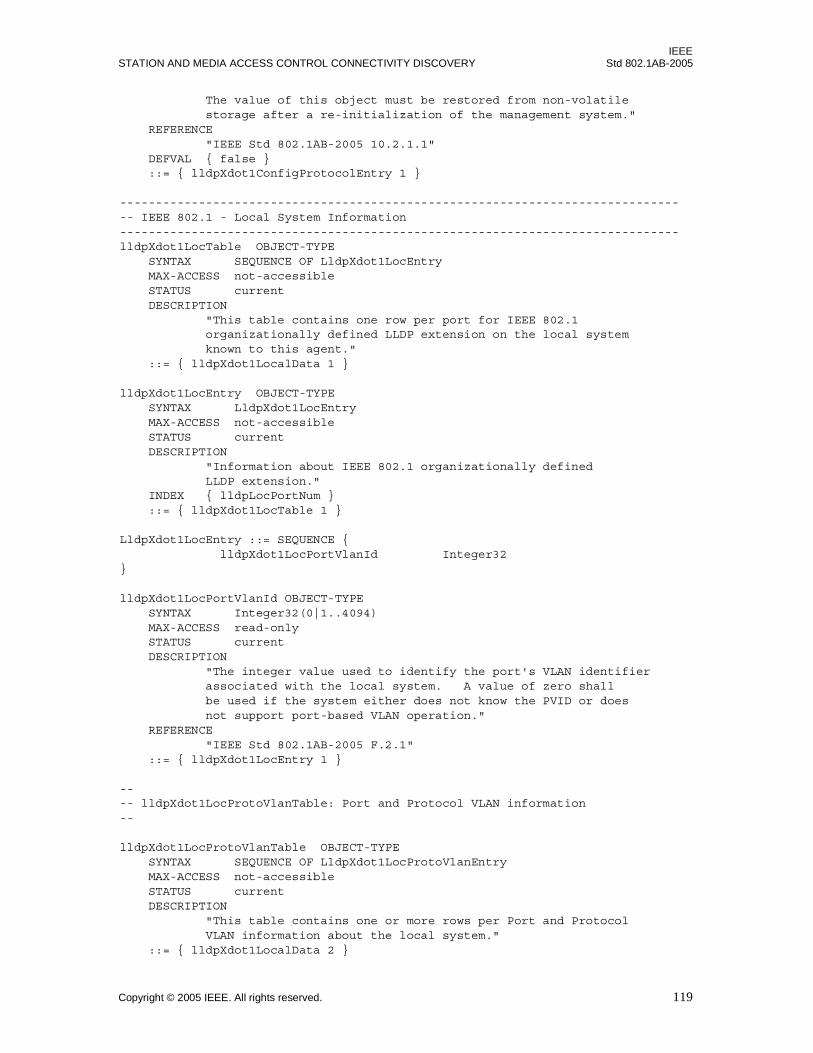
IEEESTATION AND MEDIA ACCESS CONTROL CONNECTIVITY DISCOVERY Std 802.1AB-2005
The value of this object must be restored from non-volatile storage after a re-initialization of the management system." REFERENCE "IEEE Std 802.1AB-2005 10.2.1.1" DEFVAL { false } ::= { lldpXdot1ConfigProtocolEntry 1 }
-------------------------------------------------------------------------------- IEEE 802.1 - Local System Information------------------------------------------------------------------------------lldpXdot1LocTable OBJECT-TYPE SYNTAX SEQUENCE OF LldpXdot1LocEntry MAX-ACCESS not-accessible STATUS current DESCRIPTION "This table contains one row per port for IEEE 802.1 organizationally defined LLDP extension on the local system known to this agent." ::= { lldpXdot1LocalData 1 }
lldpXdot1LocEntry OBJECT-TYPE SYNTAX LldpXdot1LocEntry MAX-ACCESS not-accessible STATUS current DESCRIPTION "Information about IEEE 802.1 organizationally defined LLDP extension." INDEX { lldpLocPortNum } ::= { lldpXdot1LocTable 1 }
LldpXdot1LocEntry ::= SEQUENCE { lldpXdot1LocPortVlanId Integer32}
lldpXdot1LocPortVlanId OBJECT-TYPE SYNTAX Integer32(0|1..4094) MAX-ACCESS read-only STATUS current DESCRIPTION "The integer value used to identify the port's VLAN identifier associated with the local system. A value of zero shall be used if the system either does not know the PVID or does not support port-based VLAN operation." REFERENCE "IEEE Std 802.1AB-2005 F.2.1" ::= { lldpXdot1LocEntry 1 }
---- lldpXdot1LocProtoVlanTable: Port and Protocol VLAN information --
lldpXdot1LocProtoVlanTable OBJECT-TYPE SYNTAX SEQUENCE OF LldpXdot1LocProtoVlanEntry MAX-ACCESS not-accessible STATUS current DESCRIPTION "This table contains one or more rows per Port and Protocol VLAN information about the local system." ::= { lldpXdot1LocalData 2 }
Copyright © 2005 IEEE. All rights reserved. 119
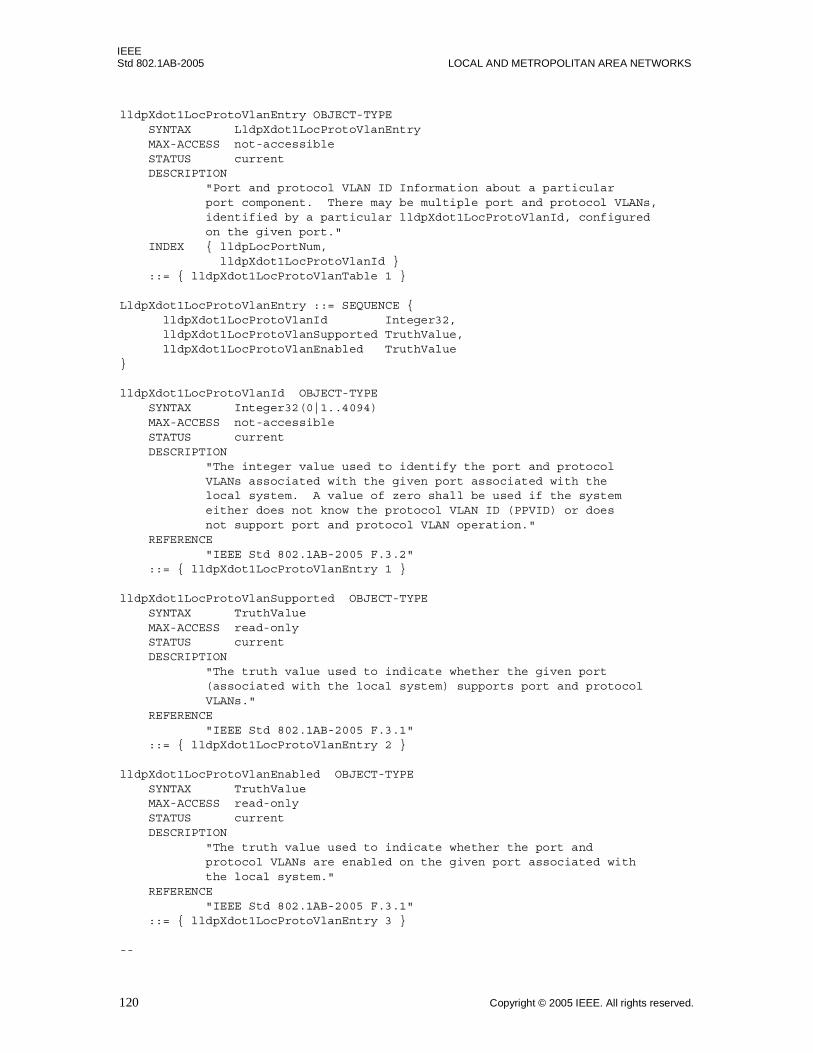
IEEEStd 802.1AB-2005 LOCAL AND METROPOLITAN AREA NETWORKS
lldpXdot1LocProtoVlanEntry OBJECT-TYPE SYNTAX LldpXdot1LocProtoVlanEntry MAX-ACCESS not-accessible STATUS current DESCRIPTION "Port and protocol VLAN ID Information about a particular port component. There may be multiple port and protocol VLANs, identified by a particular lldpXdot1LocProtoVlanId, configured on the given port." INDEX { lldpLocPortNum, lldpXdot1LocProtoVlanId } ::= { lldpXdot1LocProtoVlanTable 1 }
LldpXdot1LocProtoVlanEntry ::= SEQUENCE { lldpXdot1LocProtoVlanId Integer32, lldpXdot1LocProtoVlanSupported TruthValue, lldpXdot1LocProtoVlanEnabled TruthValue}
lldpXdot1LocProtoVlanId OBJECT-TYPE SYNTAX Integer32(0|1..4094) MAX-ACCESS not-accessible STATUS current DESCRIPTION "The integer value used to identify the port and protocol VLANs associated with the given port associated with the local system. A value of zero shall be used if the system either does not know the protocol VLAN ID (PPVID) or does not support port and protocol VLAN operation." REFERENCE "IEEE Std 802.1AB-2005 F.3.2" ::= { lldpXdot1LocProtoVlanEntry 1 }
lldpXdot1LocProtoVlanSupported OBJECT-TYPE SYNTAX TruthValue MAX-ACCESS read-only STATUS current DESCRIPTION "The truth value used to indicate whether the given port (associated with the local system) supports port and protocol VLANs." REFERENCE "IEEE Std 802.1AB-2005 F.3.1" ::= { lldpXdot1LocProtoVlanEntry 2 }
lldpXdot1LocProtoVlanEnabled OBJECT-TYPE SYNTAX TruthValue MAX-ACCESS read-only STATUS current DESCRIPTION "The truth value used to indicate whether the port and protocol VLANs are enabled on the given port associated with the local system." REFERENCE "IEEE Std 802.1AB-2005 F.3.1" ::= { lldpXdot1LocProtoVlanEntry 3 }
--
120 Copyright © 2005 IEEE. All rights reserved.
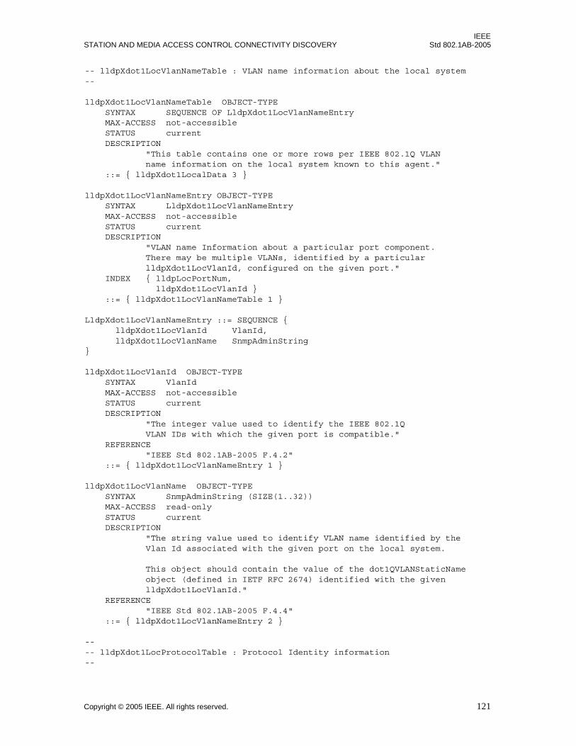
IEEESTATION AND MEDIA ACCESS CONTROL CONNECTIVITY DISCOVERY Std 802.1AB-2005
-- lldpXdot1LocVlanNameTable : VLAN name information about the local system--
lldpXdot1LocVlanNameTable OBJECT-TYPE SYNTAX SEQUENCE OF LldpXdot1LocVlanNameEntry MAX-ACCESS not-accessible STATUS current DESCRIPTION "This table contains one or more rows per IEEE 802.1Q VLAN name information on the local system known to this agent." ::= { lldpXdot1LocalData 3 }
lldpXdot1LocVlanNameEntry OBJECT-TYPE SYNTAX LldpXdot1LocVlanNameEntry MAX-ACCESS not-accessible STATUS current DESCRIPTION "VLAN name Information about a particular port component. There may be multiple VLANs, identified by a particular lldpXdot1LocVlanId, configured on the given port." INDEX { lldpLocPortNum, lldpXdot1LocVlanId } ::= { lldpXdot1LocVlanNameTable 1 }
LldpXdot1LocVlanNameEntry ::= SEQUENCE { lldpXdot1LocVlanId VlanId, lldpXdot1LocVlanName SnmpAdminString}
lldpXdot1LocVlanId OBJECT-TYPE SYNTAX VlanId MAX-ACCESS not-accessible STATUS current DESCRIPTION "The integer value used to identify the IEEE 802.1Q VLAN IDs with which the given port is compatible." REFERENCE "IEEE Std 802.1AB-2005 F.4.2" ::= { lldpXdot1LocVlanNameEntry 1 }
lldpXdot1LocVlanName OBJECT-TYPE SYNTAX SnmpAdminString (SIZE(1..32)) MAX-ACCESS read-only STATUS current DESCRIPTION "The string value used to identify VLAN name identified by the Vlan Id associated with the given port on the local system.
This object should contain the value of the dot1QVLANStaticName object (defined in IETF RFC 2674) identified with the given lldpXdot1LocVlanId." REFERENCE "IEEE Std 802.1AB-2005 F.4.4" ::= { lldpXdot1LocVlanNameEntry 2 }
---- lldpXdot1LocProtocolTable : Protocol Identity information --
Copyright © 2005 IEEE. All rights reserved. 121
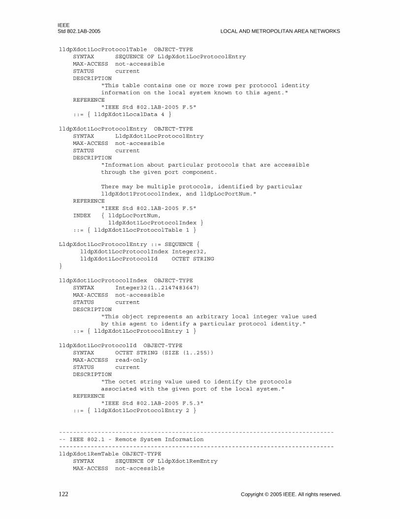
IEEEStd 802.1AB-2005 LOCAL AND METROPOLITAN AREA NETWORKS
lldpXdot1LocProtocolTable OBJECT-TYPE SYNTAX SEQUENCE OF LldpXdot1LocProtocolEntry MAX-ACCESS not-accessible STATUS current DESCRIPTION "This table contains one or more rows per protocol identity information on the local system known to this agent." REFERENCE "IEEE Std 802.1AB-2005 F.5" ::= { lldpXdot1LocalData 4 }
lldpXdot1LocProtocolEntry OBJECT-TYPE SYNTAX LldpXdot1LocProtocolEntry MAX-ACCESS not-accessible STATUS current DESCRIPTION "Information about particular protocols that are accessible through the given port component.
There may be multiple protocols, identified by particular lldpXdot1ProtocolIndex, and lldpLocPortNum." REFERENCE "IEEE Std 802.1AB-2005 F.5" INDEX { lldpLocPortNum, lldpXdot1LocProtocolIndex } ::= { lldpXdot1LocProtocolTable 1 }
LldpXdot1LocProtocolEntry ::= SEQUENCE { lldpXdot1LocProtocolIndex Integer32, lldpXdot1LocProtocolId OCTET STRING}
lldpXdot1LocProtocolIndex OBJECT-TYPE SYNTAX Integer32(1..2147483647) MAX-ACCESS not-accessible STATUS current DESCRIPTION "This object represents an arbitrary local integer value used by this agent to identify a particular protocol identity." ::= { lldpXdot1LocProtocolEntry 1 }
lldpXdot1LocProtocolId OBJECT-TYPE SYNTAX OCTET STRING (SIZE (1..255)) MAX-ACCESS read-only STATUS current DESCRIPTION "The octet string value used to identify the protocols associated with the given port of the local system." REFERENCE "IEEE Std 802.1AB-2005 F.5.3" ::= { lldpXdot1LocProtocolEntry 2 }
-------------------------------------------------------------------------------- IEEE 802.1 - Remote System Information------------------------------------------------------------------------------lldpXdot1RemTable OBJECT-TYPE SYNTAX SEQUENCE OF LldpXdot1RemEntry MAX-ACCESS not-accessible
122 Copyright © 2005 IEEE. All rights reserved.
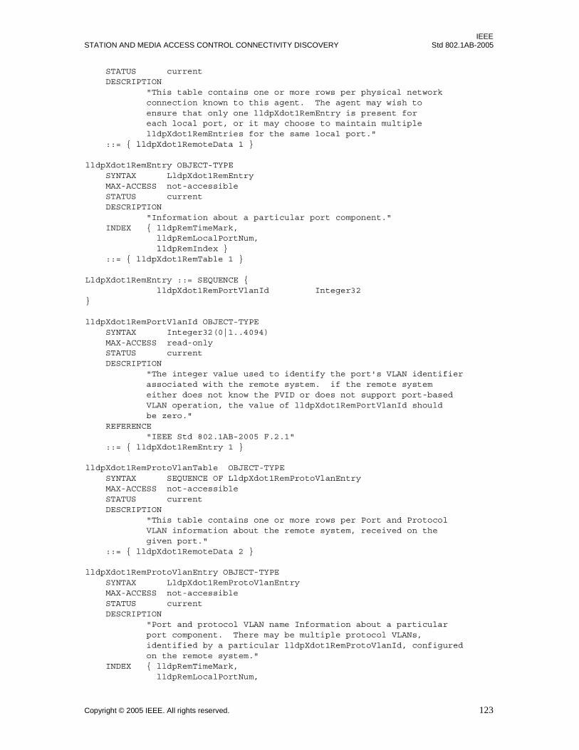
IEEESTATION AND MEDIA ACCESS CONTROL CONNECTIVITY DISCOVERY Std 802.1AB-2005
STATUS current DESCRIPTION "This table contains one or more rows per physical network connection known to this agent. The agent may wish to ensure that only one lldpXdot1RemEntry is present for each local port, or it may choose to maintain multiple lldpXdot1RemEntries for the same local port." ::= { lldpXdot1RemoteData 1 }
lldpXdot1RemEntry OBJECT-TYPE SYNTAX LldpXdot1RemEntry MAX-ACCESS not-accessible STATUS current DESCRIPTION "Information about a particular port component." INDEX { lldpRemTimeMark, lldpRemLocalPortNum, lldpRemIndex } ::= { lldpXdot1RemTable 1 }
LldpXdot1RemEntry ::= SEQUENCE { lldpXdot1RemPortVlanId Integer32}
lldpXdot1RemPortVlanId OBJECT-TYPE SYNTAX Integer32(0|1..4094) MAX-ACCESS read-only STATUS current DESCRIPTION "The integer value used to identify the port's VLAN identifier associated with the remote system. if the remote system either does not know the PVID or does not support port-based VLAN operation, the value of lldpXdot1RemPortVlanId should be zero." REFERENCE "IEEE Std 802.1AB-2005 F.2.1" ::= { lldpXdot1RemEntry 1 }
lldpXdot1RemProtoVlanTable OBJECT-TYPE SYNTAX SEQUENCE OF LldpXdot1RemProtoVlanEntry MAX-ACCESS not-accessible STATUS current DESCRIPTION "This table contains one or more rows per Port and Protocol VLAN information about the remote system, received on the given port." ::= { lldpXdot1RemoteData 2 }
lldpXdot1RemProtoVlanEntry OBJECT-TYPE SYNTAX LldpXdot1RemProtoVlanEntry MAX-ACCESS not-accessible STATUS current DESCRIPTION "Port and protocol VLAN name Information about a particular port component. There may be multiple protocol VLANs, identified by a particular lldpXdot1RemProtoVlanId, configured on the remote system." INDEX { lldpRemTimeMark, lldpRemLocalPortNum,
Copyright © 2005 IEEE. All rights reserved. 123

IEEEStd 802.1AB-2005 LOCAL AND METROPOLITAN AREA NETWORKS
lldpRemIndex, lldpXdot1RemProtoVlanId } ::= { lldpXdot1RemProtoVlanTable 1 }
LldpXdot1RemProtoVlanEntry ::= SEQUENCE { lldpXdot1RemProtoVlanId Integer32, lldpXdot1RemProtoVlanSupported TruthValue, lldpXdot1RemProtoVlanEnabled TruthValue}
lldpXdot1RemProtoVlanId OBJECT-TYPE SYNTAX Integer32(0|1..4094) MAX-ACCESS not-accessible STATUS current DESCRIPTION "The integer value used to identify the port and protocol VLANs associated with the given port associated with the remote system.
If port and protocol VLANs are not supported on the given port associated with the remote system, or if the port is not enabled with any port and protocol VLAN, the value of lldpXdot1RemProtoVlanId should be zero." REFERENCE "IEEE Std 802.1AB-2005 F.3.2" ::= { lldpXdot1RemProtoVlanEntry 1 }
lldpXdot1RemProtoVlanSupported OBJECT-TYPE SYNTAX TruthValue MAX-ACCESS read-only STATUS current DESCRIPTION "The truth value used to indicate whether the given port (associated with the remote system) is capable of supporting port and protocol VLANs." REFERENCE "IEEE Std 802.1AB-2005 F.3.1" ::= { lldpXdot1RemProtoVlanEntry 2 }
lldpXdot1RemProtoVlanEnabled OBJECT-TYPE SYNTAX TruthValue MAX-ACCESS read-only STATUS current DESCRIPTION "The truth value used to indicate whether the port and protocol VLANs are enabled on the given port associated with the remote system." REFERENCE "IEEE Std 802.1AB-2005 F.3.1" ::= { lldpXdot1RemProtoVlanEntry 3 }
-- -- lldpXdot1RemVlanNameTable : VLAN name information of the remote -- systems--
lldpXdot1RemVlanNameTable OBJECT-TYPE SYNTAX SEQUENCE OF LldpXdot1RemVlanNameEntry
124 Copyright © 2005 IEEE. All rights reserved.
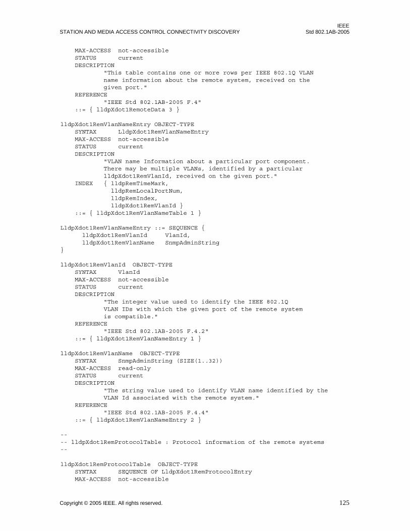
IEEESTATION AND MEDIA ACCESS CONTROL CONNECTIVITY DISCOVERY Std 802.1AB-2005
MAX-ACCESS not-accessible STATUS current DESCRIPTION "This table contains one or more rows per IEEE 802.1Q VLAN name information about the remote system, received on the given port." REFERENCE "IEEE Std 802.1AB-2005 F.4" ::= { lldpXdot1RemoteData 3 }
lldpXdot1RemVlanNameEntry OBJECT-TYPE SYNTAX LldpXdot1RemVlanNameEntry MAX-ACCESS not-accessible STATUS current DESCRIPTION "VLAN name Information about a particular port component. There may be multiple VLANs, identified by a particular lldpXdot1RemVlanId, received on the given port." INDEX { lldpRemTimeMark, lldpRemLocalPortNum, lldpRemIndex, lldpXdot1RemVlanId } ::= { lldpXdot1RemVlanNameTable 1 }
LldpXdot1RemVlanNameEntry ::= SEQUENCE { lldpXdot1RemVlanId VlanId, lldpXdot1RemVlanName SnmpAdminString}
lldpXdot1RemVlanId OBJECT-TYPE SYNTAX VlanId MAX-ACCESS not-accessible STATUS current DESCRIPTION "The integer value used to identify the IEEE 802.1Q VLAN IDs with which the given port of the remote system is compatible." REFERENCE "IEEE Std 802.1AB-2005 F.4.2" ::= { lldpXdot1RemVlanNameEntry 1 }
lldpXdot1RemVlanName OBJECT-TYPE SYNTAX SnmpAdminString (SIZE(1..32)) MAX-ACCESS read-only STATUS current DESCRIPTION "The string value used to identify VLAN name identified by the VLAN Id associated with the remote system." REFERENCE "IEEE Std 802.1AB-2005 F.4.4" ::= { lldpXdot1RemVlanNameEntry 2 }
---- lldpXdot1RemProtocolTable : Protocol information of the remote systems--
lldpXdot1RemProtocolTable OBJECT-TYPE SYNTAX SEQUENCE OF LldpXdot1RemProtocolEntry MAX-ACCESS not-accessible
Copyright © 2005 IEEE. All rights reserved. 125
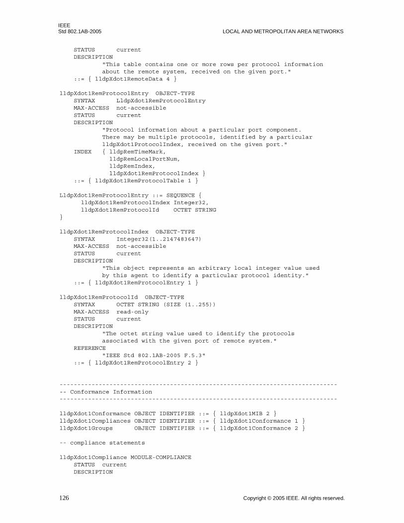
IEEEStd 802.1AB-2005 LOCAL AND METROPOLITAN AREA NETWORKS
STATUS current DESCRIPTION "This table contains one or more rows per protocol information about the remote system, received on the given port." ::= { lldpXdot1RemoteData 4 }
lldpXdot1RemProtocolEntry OBJECT-TYPE SYNTAX LldpXdot1RemProtocolEntry MAX-ACCESS not-accessible STATUS current DESCRIPTION "Protocol information about a particular port component. There may be multiple protocols, identified by a particular lldpXdot1ProtocolIndex, received on the given port." INDEX { lldpRemTimeMark, lldpRemLocalPortNum, lldpRemIndex, lldpXdot1RemProtocolIndex } ::= { lldpXdot1RemProtocolTable 1 }
LldpXdot1RemProtocolEntry ::= SEQUENCE { lldpXdot1RemProtocolIndex Integer32, lldpXdot1RemProtocolId OCTET STRING}
lldpXdot1RemProtocolIndex OBJECT-TYPE SYNTAX Integer32(1..2147483647) MAX-ACCESS not-accessible STATUS current DESCRIPTION "This object represents an arbitrary local integer value used by this agent to identify a particular protocol identity." ::= { lldpXdot1RemProtocolEntry 1 }
lldpXdot1RemProtocolId OBJECT-TYPE SYNTAX OCTET STRING (SIZE (1..255)) MAX-ACCESS read-only STATUS current DESCRIPTION "The octet string value used to identify the protocols associated with the given port of remote system." REFERENCE "IEEE Std 802.1AB-2005 F.5.3" ::= { lldpXdot1RemProtocolEntry 2 }
-------------------------------------------------------------------------------- Conformance Information------------------------------------------------------------------------------
lldpXdot1Conformance OBJECT IDENTIFIER ::= { lldpXdot1MIB 2 }lldpXdot1Compliances OBJECT IDENTIFIER ::= { lldpXdot1Conformance 1 }lldpXdot1Groups OBJECT IDENTIFIER ::= { lldpXdot1Conformance 2 }
-- compliance statements
lldpXdot1Compliance MODULE-COMPLIANCE STATUS current DESCRIPTION
126 Copyright © 2005 IEEE. All rights reserved.
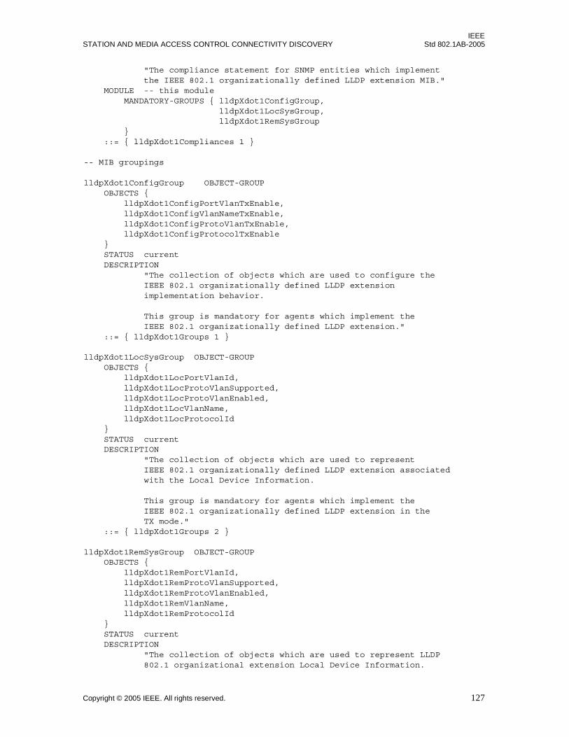
IEEESTATION AND MEDIA ACCESS CONTROL CONNECTIVITY DISCOVERY Std 802.1AB-2005
"The compliance statement for SNMP entities which implement the IEEE 802.1 organizationally defined LLDP extension MIB." MODULE -- this module MANDATORY-GROUPS { lldpXdot1ConfigGroup, lldpXdot1LocSysGroup, lldpXdot1RemSysGroup } ::= { lldpXdot1Compliances 1 }
-- MIB groupings
lldpXdot1ConfigGroup OBJECT-GROUP OBJECTS { lldpXdot1ConfigPortVlanTxEnable, lldpXdot1ConfigVlanNameTxEnable, lldpXdot1ConfigProtoVlanTxEnable, lldpXdot1ConfigProtocolTxEnable } STATUS current DESCRIPTION "The collection of objects which are used to configure the IEEE 802.1 organizationally defined LLDP extension implementation behavior.
This group is mandatory for agents which implement the IEEE 802.1 organizationally defined LLDP extension." ::= { lldpXdot1Groups 1 }
lldpXdot1LocSysGroup OBJECT-GROUP OBJECTS { lldpXdot1LocPortVlanId, lldpXdot1LocProtoVlanSupported, lldpXdot1LocProtoVlanEnabled, lldpXdot1LocVlanName, lldpXdot1LocProtocolId } STATUS current DESCRIPTION "The collection of objects which are used to represent IEEE 802.1 organizationally defined LLDP extension associated with the Local Device Information. This group is mandatory for agents which implement the IEEE 802.1 organizationally defined LLDP extension in the TX mode." ::= { lldpXdot1Groups 2 }
lldpXdot1RemSysGroup OBJECT-GROUP OBJECTS { lldpXdot1RemPortVlanId, lldpXdot1RemProtoVlanSupported, lldpXdot1RemProtoVlanEnabled, lldpXdot1RemVlanName, lldpXdot1RemProtocolId } STATUS current DESCRIPTION "The collection of objects which are used to represent LLDP 802.1 organizational extension Local Device Information.
Copyright © 2005 IEEE. All rights reserved. 127

IEEEStd 802.1AB-2005 LOCAL AND METROPOLITAN AREA NETWORKS
This group is mandatory for agents which implement the
LLDP 802.1 organizational extension in the RX mode."
::= { lldpXdot1Groups 3 }
END
F.7.2 Security considerations for IEEE 802.1 LLDP extension MIB module
There are a number of management objects defined in this MIB module with a MAX-ACCESS clause ofread-write.20 Such objects may be considered sensitive or vulnerable in some network environments. Thesupport for SET operations in a non-secure environment without proper protection can have a negativeeffect on network operations.
Setting the following objects to incorrect values can result in improper operation of LLDP when in thetransmit mode:
a) lldpXdot1ConfigPortVlanTxEnable.
b) lldpXdot1ConfigVlanNameTxEnable.
c) lldpXdot1ConfigProtoVlanTxEnable.
d) lldpXdot1ConfigProtocolTxEnable.
The following readable objects in this MIB module may be considered to be sensitive or vulnerable in somenetwork environments:
e) MIB objects that are related to the transmit mode:
1) lldpXdot1LocPortVlanId.
2) lldpXdot1LocProtoVlanSupported.
3) lldpXdot1LocProtoVlanEnabled.
4) lldpXdot1LocVlanName.
5) lldpXdot1LocProtocolId.
f) MIB objects that are related to the receive mode:
1) lldpXdot1RemPortVlanId.
2) lldpXdot1RemProtoVlanSupported.
3) lldpXdot1RemProtoVlanEnabled.
4) lldpXdot1RemVlanName.
5) lldpXdot1RemProtocolId.
This concern applies both to objects that describe the configuration of the local host, as well as for objectsthat describe information from the remote hosts, acquired via LLDP and displayed by the objects in thisMIB module. It is thus important to control even GET and/or NOTIFY access to these objects and possiblyto even encrypt the values of these objects when sending them over the network via SNMP.
SNMP versions prior to SNMPv3 did not include adequate security. Even if the network itself is secure (forexample by using IPSec), even then, there is no control as to who on the secure network is allowed to accessand GET/SET (read/change/create/delete) the objects in this MIB module.
20In IETF MIB definitions, the MAX-ACCESS clause defines the type of access that is allowed for particular dataelements in the MIB. An explanation of the MAX-ACCESS mappings is given in section 7.3 of IETF RFC 2578 [B10].
128 Copyright © 2005 IEEE. All rights reserved.

IEEESTATION AND MEDIA ACCESS CONTROL CONNECTIVITY DISCOVERY Std 802.1AB-2005
Implementers should consider the security features as provided by the SNMPv3 framework (see RFC 3410,section 8), including full support for the SNMPv3 cryptographic mechanisms (for authentication andprivacy).
Further, implementers should not deploy SNMP versions prior to SNMPv3. Instead, implementers shoulddeploy SNMPv3 to enable cryptographic security. It is then a customer/operator responsibility to ensurethat the SNMP entity giving access to an instance of this MIB module is properly configured to give accessto the objects only to those principals (users) that have legitimate rights to indeed GET or SET (change/create/delete) them.
Copyright © 2005 IEEE. All rights reserved. 129
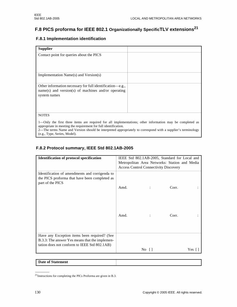
IEEEStd 802.1AB-2005 LOCAL AND METROPOLITAN AREA NETWORKS
F.8 PICS proforma for IEEE 802.1 Organizationally SpecificTLV extensions21
F.8.1 Implementation identification
Supplier
Contact point for queries about the PICS
Implementation Name(s) and Version(s)
Other information necessary for full identification—e.g.,name(s) and version(s) of machines and/or operatingsystem names
NOTES
1—Only the first three items are required for all implementations; other information may be completed asappropriate in meeting the requirement for full identification.2—The terms Name and Version should be interpreted appropriately to correspond with a supplier’s terminology(e.g., Type, Series, Model).
F.8.2 Protocol summary, IEEE Std 802.1AB-2005
Identification of protocol specification IEEE Std 802.1AB-2005, Standard for Local andMetropolitan Area Networks: Station and MediaAccess Control Connectivity Discovery
Identification of amendments and corrigenda tothe PICS proforma that have been completed aspart of the PICS
Amd. : Corr. :
Amd. : Corr. :
Have any Exception items been required? (SeeB.3.3: The answer Yes means that the implemen-tation does not conform to IEEE Std 802.1AB)
No [ ] Yes [ ]
Date of Statement
21Instructions for completing the PICs Proforma are given in B.3.
130 Copyright © 2005 IEEE. All rights reserved.
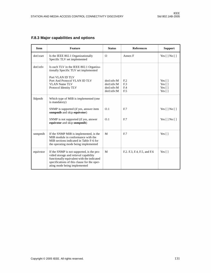
IEEESTATION AND MEDIA ACCESS CONTROL CONNECTIVITY DISCOVERY Std 802.1AB-2005
F.8.3 Major capabilities and options
Item Feature Status References Support
dot1xset Is the IEEE 802.1 OrganizationallySpecific TLV set implemented
O Annex F Yes [ ] No [ ]
dot1xtlv Is each TLV in the IEEE 802.1 Organiza-tionally Specific TLV set implemented
Port VLAN ID TLV Port And Protocol VLAN ID TLVVLAN Name TLV Protocol Identity TLV
dot1xtlv:M dot1xtlv:M dot1xtlv:M dot1xtlv:M
F.2F.3 F.4 F.5
Yes [ ] Yes [ ] Yes [ ] Yes [ ]
lldpmib Which type of MIB is implemented (one is mandatory)
SNMP is supported (if yes, answer item snmpmib and skip equivstor)
SNMP is not supported (if yes, answer equivstor and skip snmpmib)
O.1
O.1
F.7
F.7
Yes [ ] No [ ]
Yes [ ] No [ ]
snmpmib If the SNMP MIB is implemented, is the MIB module in conformance with the MIB sections indicated in Table F-6 for the operating mode being implemented
M F.7 Yes [ ]
equivstor If the SNMP is not supported, is the pro-vided storage and retieval capability functionally equivalent with the indicated specifications of this clause for the oper-ating mode being implemented
M F.2. F.3, F.4, F.5, and F.6 Yes [ ]
Copyright © 2005 IEEE. All rights reserved. 131

IEEEStd 802.1AB-2005 LOCAL AND METROPOLITAN AREA NETWORKS
Annex G
(normative)
IEEE 802.3 Organizationally Specific TLVs
G.1 Requirements of the IEEE 802.3 Organizationally Specific TLV set
If any IEEE 802.3 Organizationally Specific TLV is supported, all IEEE 802.1 Organizationally SpecificTLVs shall be supported. All IEEE 802.3 Organizationally Specific TLVs shall conform to the LLDPDU bitand octet ordering conventions of 9.1.
The currently defined IEEE 802.3 Organizationally Specific TLVs are listed in Table G-1. Any adds orchanges to these TLVs will be included in this annex.
G.2 MAC/PHY Configuration/Status TLV
The MAC/PHY Configuration/Status TLV is an optional TLV that identifies:
a) The duplex and bit-rate capability of the sending IEEE 802.3 LAN node that is connected to thephysical medium.
b) The current duplex and bit-rate settings of the sending IEEE 802.3 LAN node.
c) Whether these settings are the result of auto-negotiation during link initiation or of manual set over-ride action.
Figure G-1 shows the format of this TLV.
Figure G-1—MAC/PHY configuration/status TLV format
Table G-1—IEEE 802.3 Organizationally Specific TLVs
IEEE 802.3 subtype TLV name Subclause reference
0 reserved —
1 MAC/PHY Configuration/Status G.2
2 Power Via MDI G.3
3 Link Aggregation G.4
4 Maximum Frame Size G.5
5–255 reserved —
TLV type = 127
TLV header TLV information string
TLV informationstring length = 9
auto-negotiationsupport/status
7 bits 9 bits 2 octets
802.3subtype = 1
1 octet3 octets
PMD auto-negotiationadvertised capability
operationalMAU type
1 octet 2 octets
802.3 OUI00-12-0F
132 Copyright © 2005 IEEE. All rights reserved.

IEEESTATION AND MEDIA ACCESS CONTROL CONNECTIVITY DISCOVERY Std 802.1AB-2005
G.2.1 auto-negotiation support/status
The auto-negotiation support/status field shall contain a bit map that identifies the auto-negotiation supportand current status of the local 802.3 LAN station as defined in Table G-2. If the auto-negotiation support bit(bit 0) is one and the auto-negotiation status bit (bit 1) is zero, the 802.3 PMD operating mode will bedetermined the operational MAU type field value rather than by auto-negotiation.
G.2.2 PMD auto-negotiation advertised capability field
The PMD auto-negotiation advertised capability field shall contain an integer value as defined by theifMauAutoNegCapAdvertisedBits object in IETF RFC 3636.
G.2.3 operational MAU type
The operational MAU type field contains an integer value indicating the MAU type of the sending device.This value is derived from the list position of the corresponding dot3MauType as listed in RFC 3636 (orsubsequent revisions) and is equal to the last number in the respective dot3MauType OID. For example, ifthe ifMauType object is dot3MauType1000BaseTHD which corresponds to ‘dot3MauType 29’, thenumerical value of this field will be 29. For MAU types not listed in RFC 3636 (or subsequent revisions),the value of this field shall be set to zero. For more information, see IEEE Std 802.3-2002, IEEE Std802.3ae-2002, and IEEE Std 802.3af-2004.
G.2.4 MAC/PHY Configuration/Status TLV usage rules
An LLDPDU should contain no more than one MAC/PHY Configuration/Status TLV.
G.3 Power Via MDI TLV
Three IEEE 802.3 PMD implementations (10BASE-T, 100BASE-TX, and 1000BASE-T) allow power to besupplied over the link for connected non-powered systems. The Power Via MDI TLV allows networkmanagement to advertise and discover the MDI power support capabilities of the sending IEEE 802.3 LANstation. Figure G-2 shows the format of this TLV.
Table G-2—IEEE 802.3 auto-negotiation support/status
Bit Function Value/meaning IETF RFC 3636 reference
0 Auto-negotiation support 1 = supported 0 = not supported
ifMauAutoNegSupported
1 Auto-negotiation status 1 = enabled 0 = not enabled
ifMauAutoNegAdminStatus
2–7 — reserved —
Copyright © 2005 IEEE. All rights reserved. 133
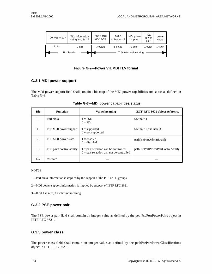
IEEEStd 802.1AB-2005 LOCAL AND METROPOLITAN AREA NETWORKS
Figure G-2—Power Via MDI TLV format
G.3.1 MDI power support
The MDI power support field shall contain a bit-map of the MDI power capabilities and status as defined inTable G-3.
NOTES
1—Port class information is implied by the support of the PSE or PD groups.
2—MDI power support information is implied by support of IETF RFC 3621.
3—If bit 1 is zero, bit 2 has no meaning.
G.3.2 PSE power pair
The PSE power pair field shall contain an integer value as defined by the pethPsePortPowerPairs object inIETF RFC 3621.
G.3.3 power class
The power class field shall contain an integer value as defined by the pethPsePortPowerClassificationsobject in IETF RFC 3621.
Table G-3—MDI power capabilities/status
Bit Function Value/meaning IETF RFC 3621 object reference
0 Port class 1 = PSE 0 = PD
See note 1
1 PSE MDI power support 1 = supported 0 = not supported
See note 2 and note 3
2 PSE MDI power state 1 = enabled0 = disabled
pethPsePortAdminEnable
3 PSE pairs control ability 1 = pair selection can be controlled0 = pair selection can not be controlled
pethPsePortPowerPairContolAbility
4–7 reserved — —
TLV header TLV information string
TLV type = 127 TLV informationstring length = 7
MDI powersupport
7 bits 9 bits
802.3subtype = 2
1 octet3 octets
PSEpowerpair
powerclass
1 octet 1 octet 1 octet
802.3 OUI00-12-0F
134 Copyright © 2005 IEEE. All rights reserved.
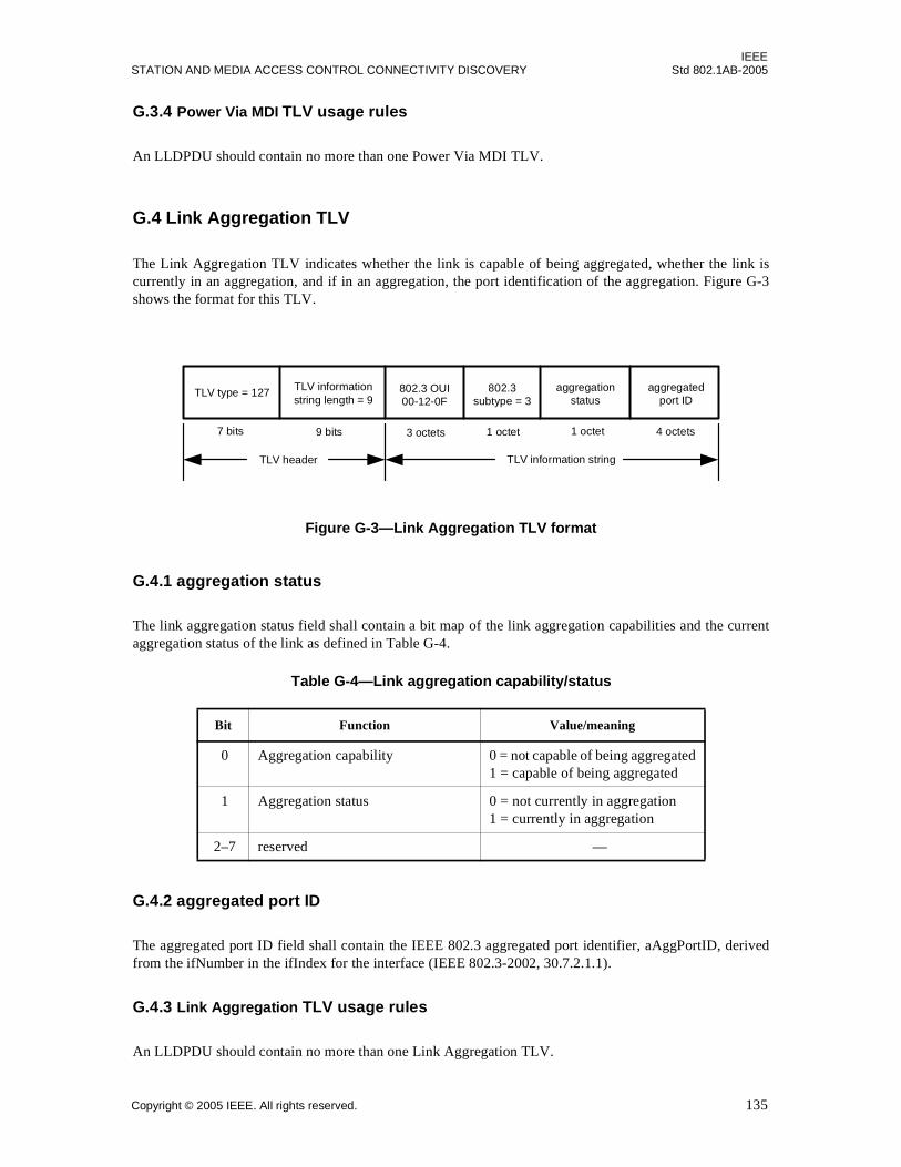
IEEESTATION AND MEDIA ACCESS CONTROL CONNECTIVITY DISCOVERY Std 802.1AB-2005
G.3.4 Power Via MDI TLV usage rules
An LLDPDU should contain no more than one Power Via MDI TLV.
G.4 Link Aggregation TLV
The Link Aggregation TLV indicates whether the link is capable of being aggregated, whether the link iscurrently in an aggregation, and if in an aggregation, the port identification of the aggregation. Figure G-3shows the format for this TLV.
Figure G-3—Link Aggregation TLV format
G.4.1 aggregation status
The link aggregation status field shall contain a bit map of the link aggregation capabilities and the currentaggregation status of the link as defined in Table G-4.
G.4.2 aggregated port ID
The aggregated port ID field shall contain the IEEE 802.3 aggregated port identifier, aAggPortID, derivedfrom the ifNumber in the ifIndex for the interface (IEEE 802.3-2002, 30.7.2.1.1).
G.4.3 Link Aggregation TLV usage rules
An LLDPDU should contain no more than one Link Aggregation TLV.
Table G-4—Link aggregation capability/status
Bit Function Value/meaning
0 Aggregation capability 0 = not capable of being aggregated1 = capable of being aggregated
1 Aggregation status 0 = not currently in aggregation1 = currently in aggregation
2–7 reserved —
TLV information string
TLV type = 127 TLV informationstring length = 9
aggregatedport ID
802.3subtype = 3
7 bits 4 octets9 bits 1 octet
TLV header
aggregationstatus
1 octet3 octets
802.3 OUI00-12-0F
Copyright © 2005 IEEE. All rights reserved. 135
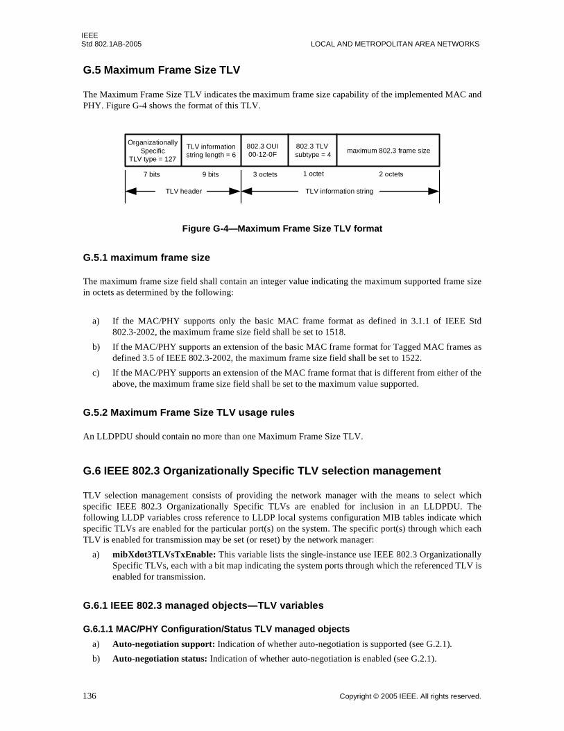
IEEEStd 802.1AB-2005 LOCAL AND METROPOLITAN AREA NETWORKS
G.5 Maximum Frame Size TLV
The Maximum Frame Size TLV indicates the maximum frame size capability of the implemented MAC andPHY. Figure G-4 shows the format of this TLV.
Figure G-4—Maximum Frame Size TLV format
G.5.1 maximum frame size
The maximum frame size field shall contain an integer value indicating the maximum supported frame sizein octets as determined by the following:
a) If the MAC/PHY supports only the basic MAC frame format as defined in 3.1.1 of IEEE Std802.3-2002, the maximum frame size field shall be set to 1518.
b) If the MAC/PHY supports an extension of the basic MAC frame format for Tagged MAC frames asdefined 3.5 of IEEE 802.3-2002, the maximum frame size field shall be set to 1522.
c) If the MAC/PHY supports an extension of the MAC frame format that is different from either of theabove, the maximum frame size field shall be set to the maximum value supported.
G.5.2 Maximum Frame Size TLV usage rules
An LLDPDU should contain no more than one Maximum Frame Size TLV.
G.6 IEEE 802.3 Organizationally Specific TLV selection management
TLV selection management consists of providing the network manager with the means to select whichspecific IEEE 802.3 Organizationally Specific TLVs are enabled for inclusion in an LLDPDU. Thefollowing LLDP variables cross reference to LLDP local systems configuration MIB tables indicate whichspecific TLVs are enabled for the particular port(s) on the system. The specific port(s) through which eachTLV is enabled for transmission may be set (or reset) by the network manager:
a) mibXdot3TLVsTxEnable: This variable lists the single-instance use IEEE 802.3 OrganizationallySpecific TLVs, each with a bit map indicating the system ports through which the referenced TLV isenabled for transmission.
G.6.1 IEEE 802.3 managed objects—TLV variables
G.6.1.1 MAC/PHY Configuration/Status TLV managed objects
a) Auto-negotiation support: Indication of whether auto-negotiation is supported (see G.2.1).
b) Auto-negotiation status: Indication of whether auto-negotiation is enabled (see G.2.1).
TLV header
OrganizationallySpecific
TLV type = 127
TLV informationstring length = 6
802.3 TLV subtype = 4
3 octets 2 octets1 octet7 bits 9 bits
TLV information string
maximum 802.3 frame size802.3 OUI00-12-0F
136 Copyright © 2005 IEEE. All rights reserved.
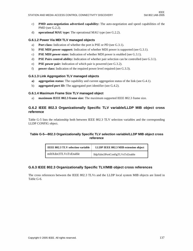
IEEESTATION AND MEDIA ACCESS CONTROL CONNECTIVITY DISCOVERY Std 802.1AB-2005
c) PMD auto-negotiation advertised capability: The auto-negotiation and speed capabilities of thePMD (see G.2.2).
d) operational MAU type: The operational MAU type (see G.2.2).
G.6.1.2 Power Via MDI TLV managed objects
a) Port class: Indication of whether the port is PSE or PD (see G.3.1).
b) PSE MDI power support: Indication of whether MDI power is supported (see G.3.1).
c) PSE MDI power state: Indication of whether MDI power is enabled (see G.3.1).
d) PSE Pairs control ability: Indication of whether pair selection can be controlled (see G.3.1).
e) PSE power pair: Indication of which pair is powered (see G.3.2).
f) power class: Indication of the required power level required (see G.3.3).
G.6.1.3 Link Aggregation TLV managed objects
a) aggregation status: The capability and current aggregation status of the link (see G.4.1).
b) aggregated port ID: The aggregated port identifier (see G.4.2).
G.6.1.4 Maximum Frame Size TLV managed object
a) maximum IEEE 802.3 frame size: The maximum supported IEEE 802.3 frame size.
G.6.2 IEEE 802.3 Organizationally Specific TLV variable/LLDP MIB object crossreference
Table G-5 lists the relationship both between IEEE 802.3 TLV selection variables and the correspondingLLDP CONFIG object.
G.6.3 IEEE 802.3 Organizationally Specific TLV/MIB object cross references
The cross references between the IEEE 802.3 TLVs and the LLDP local system MIB objects are listed inTable G-6.
Table G-5—802.3 Organizationally Specific TLV selection variable/LLDP MIB object cross reference
IEEE 802.3 TLV selection variable LLDP IEEE 802.3 MIB extension object
mibXdot3TLVsTxEnable lldpXdot3PortConfigTLVsTxEnable
Copyright © 2005 IEEE. All rights reserved. 137
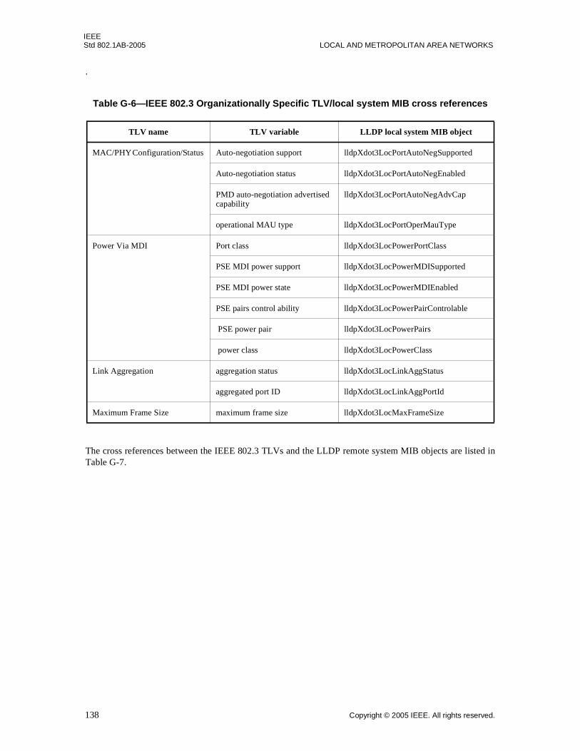
IEEEStd 802.1AB-2005 LOCAL AND METROPOLITAN AREA NETWORKS
.
The cross references between the IEEE 802.3 TLVs and the LLDP remote system MIB objects are listed inTable G-7.
Table G-6—IEEE 802.3 Organizationally Specific TLV/local system MIB cross references
TLV name TLV variable LLDP local system MIB object
MAC/PHY Configuration/Status Auto-negotiation support lldpXdot3LocPortAutoNegSupported
Auto-negotiation status lldpXdot3LocPortAutoNegEnabled
PMD auto-negotiation advertised capability
lldpXdot3LocPortAutoNegAdvCap
operational MAU type lldpXdot3LocPortOperMauType
Power Via MDI Port class lldpXdot3LocPowerPortClass
PSE MDI power support lldpXdot3LocPowerMDISupported
PSE MDI power state lldpXdot3LocPowerMDIEnabled
PSE pairs control ability lldpXdot3LocPowerPairControlable
PSE power pair lldpXdot3LocPowerPairs
power class lldpXdot3LocPowerClass
Link Aggregation aggregation status lldpXdot3LocLinkAggStatus
aggregated port ID lldpXdot3LocLinkAggPortId
Maximum Frame Size maximum frame size lldpXdot3LocMaxFrameSize
138 Copyright © 2005 IEEE. All rights reserved.
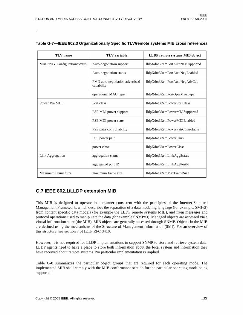
IEEESTATION AND MEDIA ACCESS CONTROL CONNECTIVITY DISCOVERY Std 802.1AB-2005
.
G.7 IEEE 802.1/LLDP extension MIB
This MIB is designed to operate in a manner consistent with the principles of the Internet-StandardManagement Framework, which describes the separation of a data modeling language (for example, SMIv2)from content specific data models (for example the LLDP remote systems MIB), and from messages andprotocol operations used to manipulate the data (for example SNMPv3). Managed objects are accessed via avirtual information store (the MIB). MIB objects are generally accessed through SNMP. Objects in the MIBare defined using the mechanisms of the Structure of Management Information (SMI). For an overview ofthis structure, see section 7 of IETF RFC 3410.
However, it is not required for LLDP implementations to support SNMP to store and retrieve system data.LLDP agents need to have a place to store both information about the local system and information theyhave received about remote systems. No particular implementation is implied.
Table G-8 summarizes the particular object groups that are required for each operating mode. Theimplemented MIB shall comply with the MIB conformance section for the particular operating mode beingsupported.
Table G-7—IEEE 802.3 Organizationally Specific TLV/remote systems MIB cross references
TLV name TLV variable LLDP remote systems MIB object
MAC/PHY Configuration/Status Auto-negotiation support lldpXdot3RemPortAutoNegSupported
Auto-negotiation status lldpXdot3RemPortAutoNegEnabled
PMD auto-negotiation advertised capability
lldpXdot3RemPortAutoNegAdvCap
operational MAU type lldpXdot3RemPortOperMauType
Power Via MDI Port class lldpXdot3RemPowerPortClass
PSE MDI power support lldpXdot3RemPowerMDISupported
PSE MDI power state lldpXdot3RemPowerMDIEnabled
PSE pairs control ability lldpXdot3RemPowerPairControlable
PSE power pair lldpXdot3RemPowerPairs
power class lldpXdot3RemPowerClass
Link Aggregation aggregation status lldpXdot3RemLinkAggStatus
aggregated port ID lldpXdot3RemLinkAggPortId
Maximum Frame Size maximum frame size lldpXdot3RemMaxFrameSize
Copyright © 2005 IEEE. All rights reserved. 139
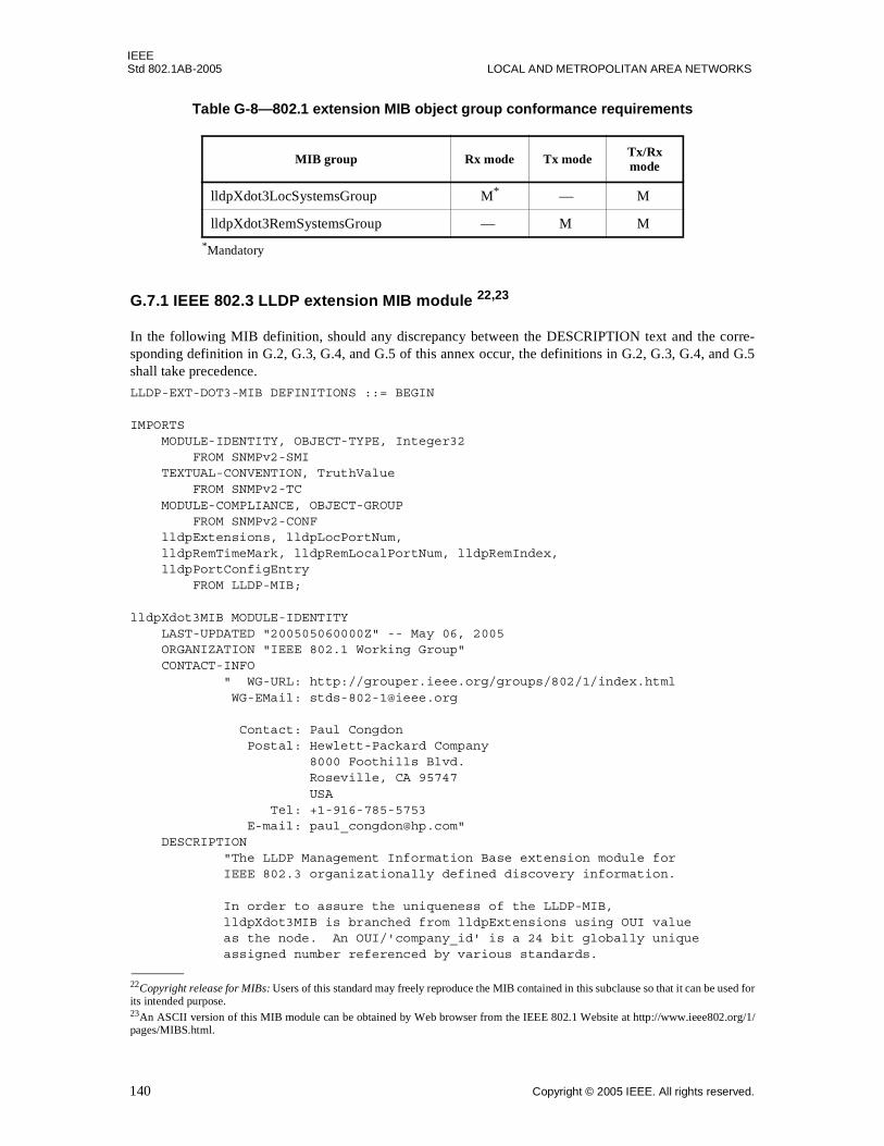
IEEEStd 802.1AB-2005 LOCAL AND METROPOLITAN AREA NETWORKS
G.7.1 IEEE 802.3 LLDP extension MIB module 22,23
In the following MIB definition, should any discrepancy between the DESCRIPTION text and the corre-sponding definition in G.2, G.3, G.4, and G.5 of this annex occur, the definitions in G.2, G.3, G.4, and G.5shall take precedence.
LLDP-EXT-DOT3-MIB DEFINITIONS ::= BEGIN
IMPORTS MODULE-IDENTITY, OBJECT-TYPE, Integer32 FROM SNMPv2-SMI TEXTUAL-CONVENTION, TruthValue FROM SNMPv2-TC MODULE-COMPLIANCE, OBJECT-GROUP FROM SNMPv2-CONF lldpExtensions, lldpLocPortNum, lldpRemTimeMark, lldpRemLocalPortNum, lldpRemIndex, lldpPortConfigEntry FROM LLDP-MIB;
lldpXdot3MIB MODULE-IDENTITY LAST-UPDATED "200505060000Z" -- May 06, 2005 ORGANIZATION "IEEE 802.1 Working Group" CONTACT-INFO " WG-URL: http://grouper.ieee.org/groups/802/1/index.html WG-EMail: [email protected]
Contact: Paul Congdon Postal: Hewlett-Packard Company 8000 Foothills Blvd. Roseville, CA 95747 USA Tel: +1-916-785-5753 E-mail: [email protected]" DESCRIPTION "The LLDP Management Information Base extension module for IEEE 802.3 organizationally defined discovery information.
In order to assure the uniqueness of the LLDP-MIB, lldpXdot3MIB is branched from lldpExtensions using OUI value as the node. An OUI/'company_id' is a 24 bit globally unique assigned number referenced by various standards.
Table G-8—802.1 extension MIB object group conformance requirements
MIB group Rx mode Tx mode Tx/Rx mode
lldpXdot3LocSystemsGroup M* — M
lldpXdot3RemSystemsGroup — M M
*Mandatory
22Copyright release for MIBs: Users of this standard may freely reproduce the MIB contained in this subclause so that it can be used forits intended purpose. 23An ASCII version of this MIB module can be obtained by Web browser from the IEEE 802.1 Website at http://www.ieee802.org/1/pages/MIBS.html.
140 Copyright © 2005 IEEE. All rights reserved.
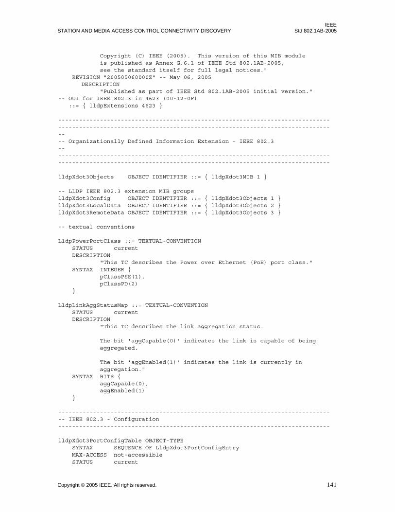
IEEESTATION AND MEDIA ACCESS CONTROL CONNECTIVITY DISCOVERY Std 802.1AB-2005
Copyright (C) IEEE (2005). This version of this MIB module is published as Annex G.6.1 of IEEE Std 802.1AB-2005; see the standard itself for full legal notices." REVISION "200505060000Z" -- May 06, 2005
DESCRIPTION "Published as part of IEEE Std 802.1AB-2005 initial version."-- OUI for IEEE 802.3 is 4623 (00-12-0F) ::= { lldpExtensions 4623 }
---------------------------------------------------------------------------------------------------------------------------------------------------------------- Organizationally Defined Information Extension - IEEE 802.3--------------------------------------------------------------------------------------------------------------------------------------------------------------
lldpXdot3Objects OBJECT IDENTIFIER ::= { lldpXdot3MIB 1 }
-- LLDP IEEE 802.3 extension MIB groupslldpXdot3Config OBJECT IDENTIFIER ::= { lldpXdot3Objects 1 }lldpXdot3LocalData OBJECT IDENTIFIER ::= { lldpXdot3Objects 2 }lldpXdot3RemoteData OBJECT IDENTIFIER ::= { lldpXdot3Objects 3 }
-- textual conventions
LldpPowerPortClass ::= TEXTUAL-CONVENTION STATUS current DESCRIPTION "This TC describes the Power over Ethernet (PoE) port class." SYNTAX INTEGER { pClassPSE(1), pClassPD(2) }
LldpLinkAggStatusMap ::= TEXTUAL-CONVENTION STATUS current DESCRIPTION "This TC describes the link aggregation status.
The bit 'aggCapable(0)' indicates the link is capable of being aggregated.
The bit 'aggEnabled(1)' indicates the link is currently in aggregation." SYNTAX BITS { aggCapable(0), aggEnabled(1) }
-------------------------------------------------------------------------------- IEEE 802.3 - Configuration------------------------------------------------------------------------------
lldpXdot3PortConfigTable OBJECT-TYPE SYNTAX SEQUENCE OF LldpXdot3PortConfigEntry MAX-ACCESS not-accessible STATUS current
Copyright © 2005 IEEE. All rights reserved. 141
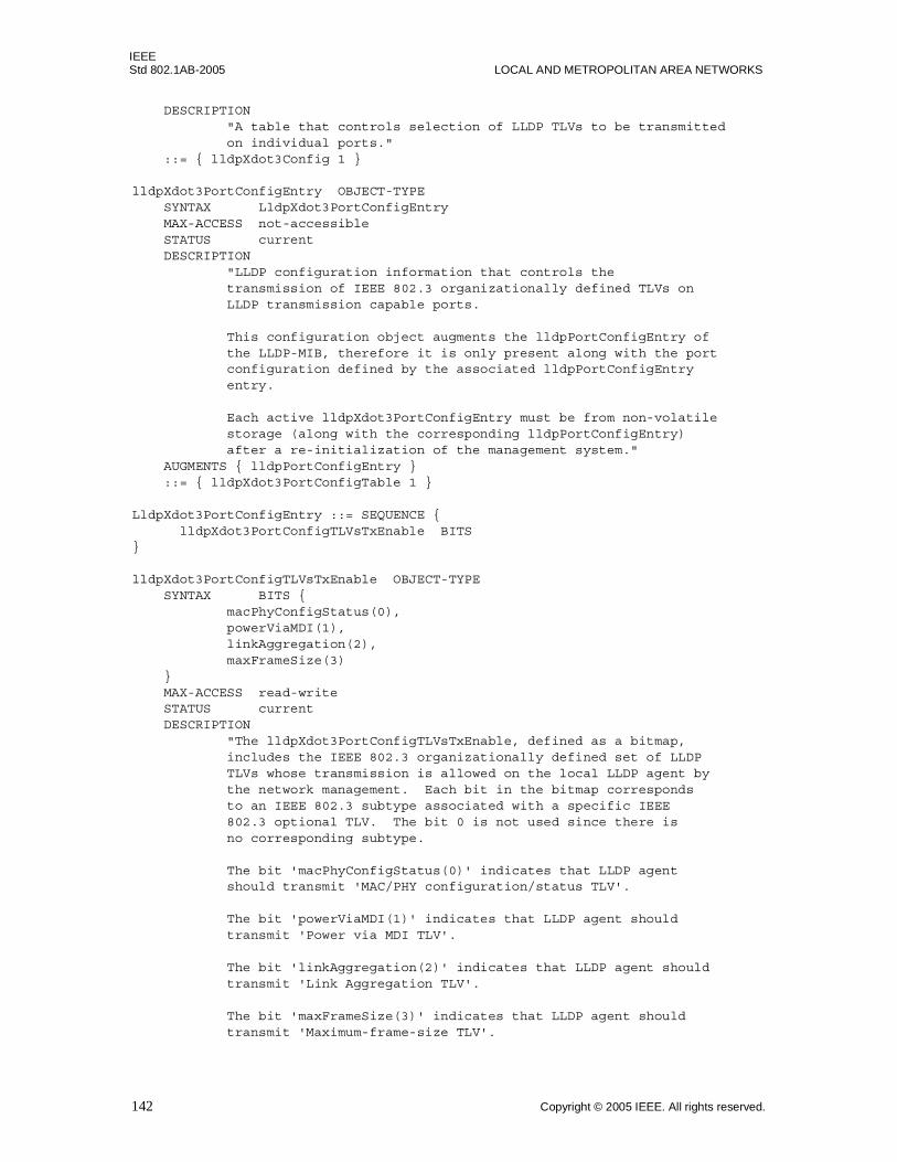
IEEEStd 802.1AB-2005 LOCAL AND METROPOLITAN AREA NETWORKS
DESCRIPTION "A table that controls selection of LLDP TLVs to be transmitted on individual ports." ::= { lldpXdot3Config 1 }
lldpXdot3PortConfigEntry OBJECT-TYPE SYNTAX LldpXdot3PortConfigEntry MAX-ACCESS not-accessible STATUS current DESCRIPTION "LLDP configuration information that controls the transmission of IEEE 802.3 organizationally defined TLVs on LLDP transmission capable ports.
This configuration object augments the lldpPortConfigEntry of the LLDP-MIB, therefore it is only present along with the port configuration defined by the associated lldpPortConfigEntry entry.
Each active lldpXdot3PortConfigEntry must be from non-volatile storage (along with the corresponding lldpPortConfigEntry) after a re-initialization of the management system." AUGMENTS { lldpPortConfigEntry } ::= { lldpXdot3PortConfigTable 1 }
LldpXdot3PortConfigEntry ::= SEQUENCE { lldpXdot3PortConfigTLVsTxEnable BITS}
lldpXdot3PortConfigTLVsTxEnable OBJECT-TYPE SYNTAX BITS { macPhyConfigStatus(0), powerViaMDI(1), linkAggregation(2), maxFrameSize(3) } MAX-ACCESS read-write STATUS current DESCRIPTION "The lldpXdot3PortConfigTLVsTxEnable, defined as a bitmap, includes the IEEE 802.3 organizationally defined set of LLDP TLVs whose transmission is allowed on the local LLDP agent by the network management. Each bit in the bitmap corresponds to an IEEE 802.3 subtype associated with a specific IEEE 802.3 optional TLV. The bit 0 is not used since there is no corresponding subtype.
The bit 'macPhyConfigStatus(0)' indicates that LLDP agent should transmit 'MAC/PHY configuration/status TLV'.
The bit 'powerViaMDI(1)' indicates that LLDP agent should transmit 'Power via MDI TLV'.
The bit 'linkAggregation(2)' indicates that LLDP agent should transmit 'Link Aggregation TLV'.
The bit 'maxFrameSize(3)' indicates that LLDP agent should transmit 'Maximum-frame-size TLV'.
142 Copyright © 2005 IEEE. All rights reserved.
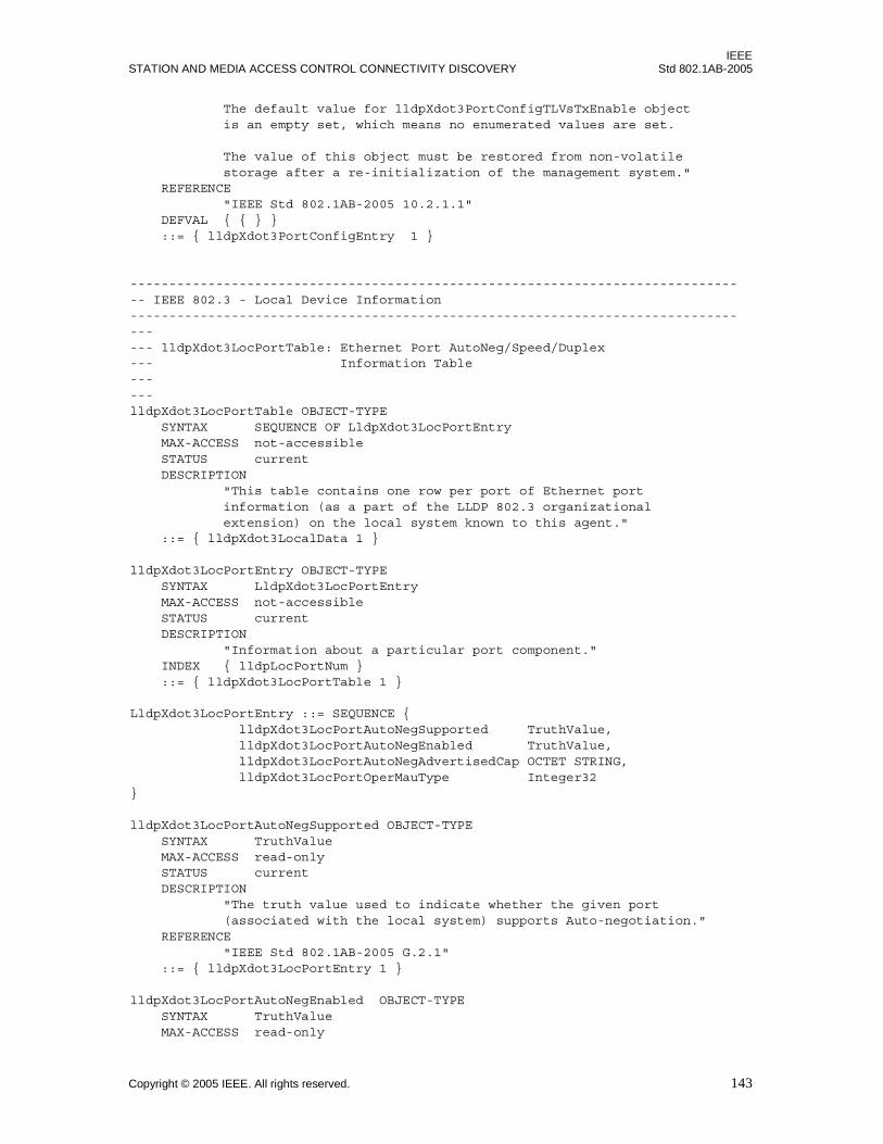
IEEESTATION AND MEDIA ACCESS CONTROL CONNECTIVITY DISCOVERY Std 802.1AB-2005
The default value for lldpXdot3PortConfigTLVsTxEnable object is an empty set, which means no enumerated values are set.
The value of this object must be restored from non-volatile storage after a re-initialization of the management system." REFERENCE "IEEE Std 802.1AB-2005 10.2.1.1" DEFVAL { { } } ::= { lldpXdot3PortConfigEntry 1 }
-------------------------------------------------------------------------------- IEEE 802.3 - Local Device Information ------------------------------------------------------------------------------------ lldpXdot3LocPortTable: Ethernet Port AutoNeg/Speed/Duplex--- Information Table------lldpXdot3LocPortTable OBJECT-TYPE SYNTAX SEQUENCE OF LldpXdot3LocPortEntry MAX-ACCESS not-accessible STATUS current DESCRIPTION "This table contains one row per port of Ethernet port information (as a part of the LLDP 802.3 organizational extension) on the local system known to this agent." ::= { lldpXdot3LocalData 1 }
lldpXdot3LocPortEntry OBJECT-TYPE SYNTAX LldpXdot3LocPortEntry MAX-ACCESS not-accessible STATUS current DESCRIPTION "Information about a particular port component." INDEX { lldpLocPortNum } ::= { lldpXdot3LocPortTable 1 }
LldpXdot3LocPortEntry ::= SEQUENCE { lldpXdot3LocPortAutoNegSupported TruthValue, lldpXdot3LocPortAutoNegEnabled TruthValue, lldpXdot3LocPortAutoNegAdvertisedCap OCTET STRING, lldpXdot3LocPortOperMauType Integer32}
lldpXdot3LocPortAutoNegSupported OBJECT-TYPE SYNTAX TruthValue MAX-ACCESS read-only STATUS current DESCRIPTION "The truth value used to indicate whether the given port (associated with the local system) supports Auto-negotiation." REFERENCE "IEEE Std 802.1AB-2005 G.2.1" ::= { lldpXdot3LocPortEntry 1 }
lldpXdot3LocPortAutoNegEnabled OBJECT-TYPE SYNTAX TruthValue MAX-ACCESS read-only
Copyright © 2005 IEEE. All rights reserved. 143

IEEEStd 802.1AB-2005 LOCAL AND METROPOLITAN AREA NETWORKS
STATUS current DESCRIPTION "The truth value used to indicate whether port Auto-negotiation is enabled on the given port associated with the local system." REFERENCE "IEEE Std 802.1AB-2005 G.2.1" ::= { lldpXdot3LocPortEntry 2 }
lldpXdot3LocPortAutoNegAdvertisedCap OBJECT-TYPE SYNTAX OCTET STRING(SIZE(2)) MAX-ACCESS read-only STATUS current DESCRIPTION "This object contains the value (bitmap) of the ifMauAutoNegCapAdvertisedBits object (defined in IETF RFC 3636) which is associated with the given port on the local system." REFERENCE "IEEE Std 802.1AB-2005 G.2.2" ::= { lldpXdot3LocPortEntry 3 }
lldpXdot3LocPortOperMauType OBJECT-TYPE SYNTAX Integer32(0..2147483647) MAX-ACCESS read-only STATUS current DESCRIPTION "An integer value that indicates the operational MAU type of the given port on the local system.
This object contains the integer value derived from the list position of the corresponding dot3MauType as listed in IETF RFC 3636 (or subsequent revisions) and is equal to the last number in the respective dot3MauType OID. For example, if the ifMauType object is dot3MauType1000BaseTHD which corresponds to {dot3MauType 29}, the numerical value of this field will be 29. For MAU types not listed in RFC 3636 (or subsequent revisions), the value of this field shall be set to zero." REFERENCE "IEEE Std 802.1AB-2005 G.2.3" ::= { lldpXdot3LocPortEntry 4 }
--------- lldpXdot3LocPowerTable: Power Ethernet Information Table------lldpXdot3LocPowerTable OBJECT-TYPE SYNTAX SEQUENCE OF LldpXdot3LocPowerEntry MAX-ACCESS not-accessible STATUS current DESCRIPTION "This table contains one row per port of power ethernet information (as a part of the LLDP 802.3 organizational extension) on the local system known to this agent." ::= { lldpXdot3LocalData 2 }
144 Copyright © 2005 IEEE. All rights reserved.
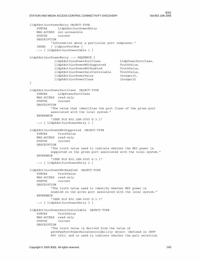
IEEESTATION AND MEDIA ACCESS CONTROL CONNECTIVITY DISCOVERY Std 802.1AB-2005
lldpXdot3LocPowerEntry OBJECT-TYPE SYNTAX LldpXdot3LocPowerEntry MAX-ACCESS not-accessible STATUS current DESCRIPTION "Information about a particular port component." INDEX { lldpLocPortNum } ::= { lldpXdot3LocPowerTable 1 }
LldpXdot3LocPowerEntry ::= SEQUENCE { lldpXdot3LocPowerPortClass LldpPowerPortClass, lldpXdot3LocPowerMDISupported TruthValue, lldpXdot3LocPowerMDIEnabled TruthValue, lldpXdot3LocPowerPairControlable TruthValue, lldpXdot3LocPowerPairs Integer32, lldpXdot3LocPowerClass Integer32}
lldpXdot3LocPowerPortClass OBJECT-TYPE SYNTAX LldpPowerPortClass MAX-ACCESS read-only STATUS current DESCRIPTION "The value that identifies the port Class of the given port associated with the local system." REFERENCE "IEEE Std 802.1AB-2005 G.3.1" ::= { lldpXdot3LocPowerEntry 1 }
lldpXdot3LocPowerMDISupported OBJECT-TYPE SYNTAX TruthValue MAX-ACCESS read-only STATUS current DESCRIPTION "The truth value used to indicate whether the MDI power is supported on the given port associated with the local system." REFERENCE "IEEE Std 802.1AB-2005 G.3.1" ::= { lldpXdot3LocPowerEntry 2 }
lldpXdot3LocPowerMDIEnabled OBJECT-TYPE SYNTAX TruthValue MAX-ACCESS read-only STATUS current DESCRIPTION "The truth value used to identify whether MDI power is enabled on the given port associated with the local system." REFERENCE "IEEE Std 802.1AB-2005 G.3.1" ::= { lldpXdot3LocPowerEntry 3 }
lldpXdot3LocPowerPairControlable OBJECT-TYPE SYNTAX TruthValue MAX-ACCESS read-only STATUS current DESCRIPTION "The truth value is derived from the value of pethPsePortPowerPairsControlAbility object (defined in IETF RFC 3621) and is used to indicate whether the pair selection
Copyright © 2005 IEEE. All rights reserved. 145
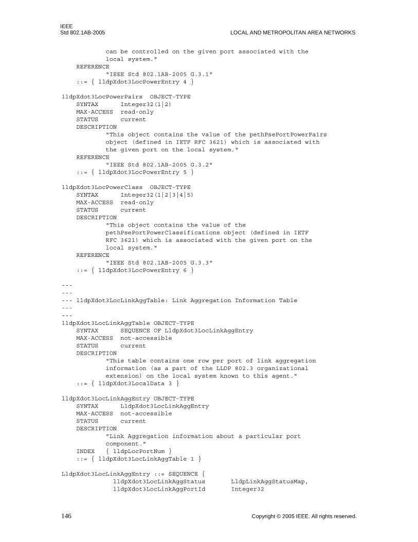
IEEEStd 802.1AB-2005 LOCAL AND METROPOLITAN AREA NETWORKS
can be controlled on the given port associated with the local system." REFERENCE "IEEE Std 802.1AB-2005 G.3.1" ::= { lldpXdot3LocPowerEntry 4 }
lldpXdot3LocPowerPairs OBJECT-TYPE SYNTAX Integer32(1|2) MAX-ACCESS read-only STATUS current DESCRIPTION "This object contains the value of the pethPsePortPowerPairs object (defined in IETF RFC 3621) which is associated with the given port on the local system." REFERENCE "IEEE Std 802.1AB-2005 G.3.2" ::= { lldpXdot3LocPowerEntry 5 }
lldpXdot3LocPowerClass OBJECT-TYPE SYNTAX Integer32(1|2|3|4|5) MAX-ACCESS read-only STATUS current DESCRIPTION "This object contains the value of the pethPsePortPowerClassifications object (defined in IETF RFC 3621) which is associated with the given port on the local system." REFERENCE "IEEE Std 802.1AB-2005 G.3.3" ::= { lldpXdot3LocPowerEntry 6 }
--------- lldpXdot3LocLinkAggTable: Link Aggregation Information Table------lldpXdot3LocLinkAggTable OBJECT-TYPE SYNTAX SEQUENCE OF LldpXdot3LocLinkAggEntry MAX-ACCESS not-accessible STATUS current DESCRIPTION "This table contains one row per port of link aggregation information (as a part of the LLDP 802.3 organizational extension) on the local system known to this agent." ::= { lldpXdot3LocalData 3 }
lldpXdot3LocLinkAggEntry OBJECT-TYPE SYNTAX LldpXdot3LocLinkAggEntry MAX-ACCESS not-accessible STATUS current DESCRIPTION "Link Aggregation information about a particular port component." INDEX { lldpLocPortNum } ::= { lldpXdot3LocLinkAggTable 1 }
LldpXdot3LocLinkAggEntry ::= SEQUENCE { lldpXdot3LocLinkAggStatus LldpLinkAggStatusMap, lldpXdot3LocLinkAggPortId Integer32
146 Copyright © 2005 IEEE. All rights reserved.
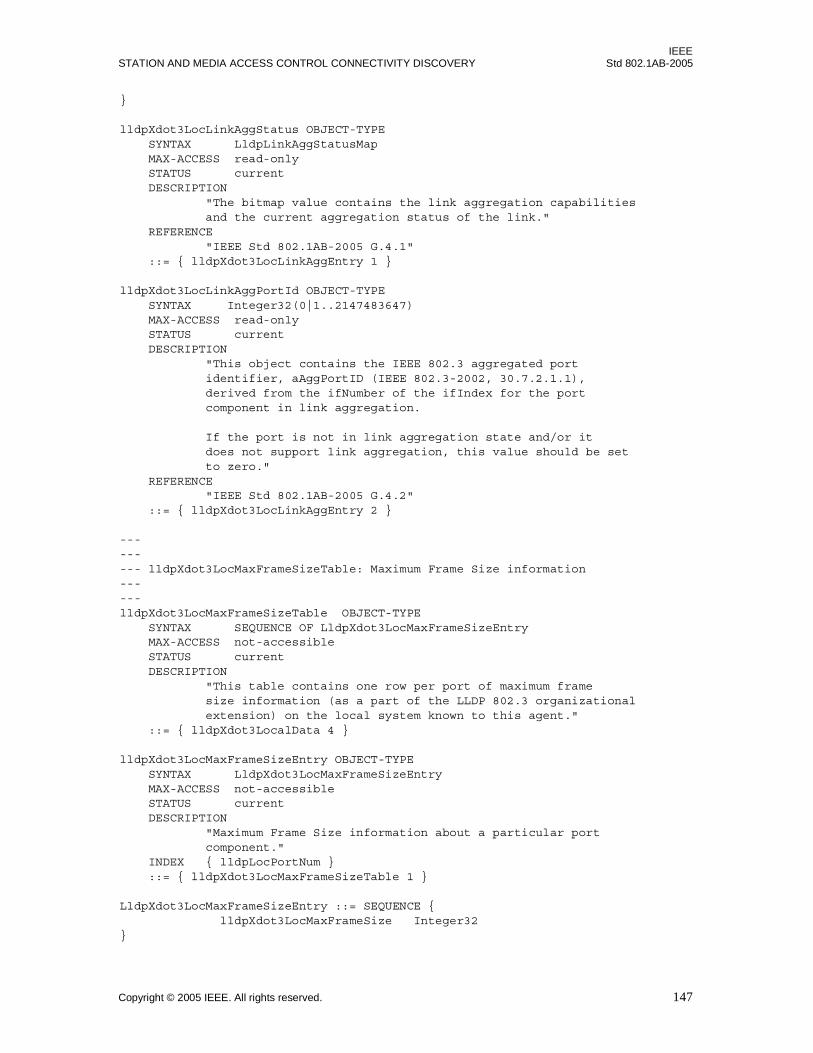
IEEESTATION AND MEDIA ACCESS CONTROL CONNECTIVITY DISCOVERY Std 802.1AB-2005
}
lldpXdot3LocLinkAggStatus OBJECT-TYPE SYNTAX LldpLinkAggStatusMap MAX-ACCESS read-only STATUS current DESCRIPTION "The bitmap value contains the link aggregation capabilities and the current aggregation status of the link." REFERENCE "IEEE Std 802.1AB-2005 G.4.1" ::= { lldpXdot3LocLinkAggEntry 1 }
lldpXdot3LocLinkAggPortId OBJECT-TYPE SYNTAX Integer32(0|1..2147483647) MAX-ACCESS read-only STATUS current DESCRIPTION "This object contains the IEEE 802.3 aggregated port identifier, aAggPortID (IEEE 802.3-2002, 30.7.2.1.1), derived from the ifNumber of the ifIndex for the port component in link aggregation.
If the port is not in link aggregation state and/or it does not support link aggregation, this value should be set to zero." REFERENCE "IEEE Std 802.1AB-2005 G.4.2" ::= { lldpXdot3LocLinkAggEntry 2 }
--------- lldpXdot3LocMaxFrameSizeTable: Maximum Frame Size information ------lldpXdot3LocMaxFrameSizeTable OBJECT-TYPE SYNTAX SEQUENCE OF LldpXdot3LocMaxFrameSizeEntry MAX-ACCESS not-accessible STATUS current DESCRIPTION "This table contains one row per port of maximum frame size information (as a part of the LLDP 802.3 organizational extension) on the local system known to this agent." ::= { lldpXdot3LocalData 4 }
lldpXdot3LocMaxFrameSizeEntry OBJECT-TYPE SYNTAX LldpXdot3LocMaxFrameSizeEntry MAX-ACCESS not-accessible STATUS current DESCRIPTION "Maximum Frame Size information about a particular port component." INDEX { lldpLocPortNum } ::= { lldpXdot3LocMaxFrameSizeTable 1 }
LldpXdot3LocMaxFrameSizeEntry ::= SEQUENCE { lldpXdot3LocMaxFrameSize Integer32}
Copyright © 2005 IEEE. All rights reserved. 147

IEEEStd 802.1AB-2005 LOCAL AND METROPOLITAN AREA NETWORKS
lldpXdot3LocMaxFrameSize OBJECT-TYPE SYNTAX Integer32(0..65535) MAX-ACCESS read-only STATUS current DESCRIPTION "An integer value indicating the maximum supported frame size in octets on the given port of the local system." REFERENCE "IEEE Std 802.1AB-2005 G.5.1" ::= { lldpXdot3LocMaxFrameSizeEntry 1 }
-------------------------------------------------------------------------------- IEEE 802.3 - Remote Devices Information--------------------------------------------------------------------------------------- lldpXdot3RemPortTable: Ethernet Information Table------lldpXdot3RemPortTable OBJECT-TYPE SYNTAX SEQUENCE OF LldpXdot3RemPortEntry MAX-ACCESS not-accessible STATUS current DESCRIPTION "This table contains Ethernet port information (as a part of the LLDP 802.3 organizational extension) of the remote system." ::= { lldpXdot3RemoteData 1 }
lldpXdot3RemPortEntry OBJECT-TYPE SYNTAX LldpXdot3RemPortEntry MAX-ACCESS not-accessible STATUS current DESCRIPTION "Information about a particular physical network connection." INDEX { lldpRemTimeMark, lldpRemLocalPortNum, lldpRemIndex } ::= { lldpXdot3RemPortTable 1 }
LldpXdot3RemPortEntry ::= SEQUENCE { lldpXdot3RemPortAutoNegSupported TruthValue, lldpXdot3RemPortAutoNegEnabled TruthValue, lldpXdot3RemPortAutoNegAdvertisedCap OCTET STRING, lldpXdot3RemPortOperMauType Integer32}
lldpXdot3RemPortAutoNegSupported OBJECT-TYPE SYNTAX TruthValue MAX-ACCESS read-only STATUS current DESCRIPTION "The truth value used to indicate whether the given port (associated with remote system) supports Auto-negotiation." REFERENCE "IEEE Std 802.1AB-2005 G.2.1" ::= { lldpXdot3RemPortEntry 1 }
148 Copyright © 2005 IEEE. All rights reserved.

IEEESTATION AND MEDIA ACCESS CONTROL CONNECTIVITY DISCOVERY Std 802.1AB-2005
lldpXdot3RemPortAutoNegEnabled OBJECT-TYPE SYNTAX TruthValue MAX-ACCESS read-only STATUS current DESCRIPTION "The truth value used to indicate whether port Auto-negotiation is enabled on the given port associated with the remote system." REFERENCE "IEEE Std 802.1AB-2005 G.2.1" ::= { lldpXdot3RemPortEntry 2 }
lldpXdot3RemPortAutoNegAdvertisedCap OBJECT-TYPE SYNTAX OCTET STRING(SIZE(2)) MAX-ACCESS read-only STATUS current DESCRIPTION "This object contains the value (bitmap) of the ifMauAutoNegCapAdvertisedBits object (defined in IETF RFC 3636) which is associated with the given port on the remote system." REFERENCE "IEEE Std 802.1AB-2005 G.2.2" ::= { lldpXdot3RemPortEntry 3 }
lldpXdot3RemPortOperMauType OBJECT-TYPE SYNTAX Integer32(0..2147483647) MAX-ACCESS read-only STATUS current DESCRIPTION "An integer value that indicates the operational MAU type of the sending device.
This object contains the integer value derived from the list position of the corresponding dot3MauType as listed in in IETF RFC 3636 (or subsequent revisions) and is equal to the last number in the respective dot3MauType OID. For example, if the ifMauType object is dot3MauType1000BaseTHD which corresponds to {dot3MauType 29}, the numerical value of this field will be 29. For MAU types not listed in RFC 3636 (or subsequent revisions), the value of this field shall be set to zero." REFERENCE "IEEE Std 802.1AB-2005 G.2.3" ::= { lldpXdot3RemPortEntry 4 }
--------- lldpXdot3RemPowerTable: Power Ethernet Information Table------lldpXdot3RemPowerTable OBJECT-TYPE SYNTAX SEQUENCE OF LldpXdot3RemPowerEntry MAX-ACCESS not-accessible STATUS current DESCRIPTION "This table contains Ethernet power information (as a part of the LLDP 802.3 organizational extension) of the remote
Copyright © 2005 IEEE. All rights reserved. 149
IEEEStd 802.1AB-2005 LOCAL AND METROPOLITAN AREA NETWORKS
system." ::= { lldpXdot3RemoteData 2 }
lldpXdot3RemPowerEntry OBJECT-TYPE SYNTAX LldpXdot3RemPowerEntry MAX-ACCESS not-accessible STATUS current DESCRIPTION "Information about a particular physical network connection." INDEX { lldpRemTimeMark, lldpRemLocalPortNum, lldpRemIndex } ::= { lldpXdot3RemPowerTable 1 }
LldpXdot3RemPowerEntry ::= SEQUENCE { lldpXdot3RemPowerPortClass LldpPowerPortClass, lldpXdot3RemPowerMDISupported TruthValue, lldpXdot3RemPowerMDIEnabled TruthValue, lldpXdot3RemPowerPairControlable TruthValue, lldpXdot3RemPowerPairs Integer32, lldpXdot3RemPowerClass Integer32}
lldpXdot3RemPowerPortClass OBJECT-TYPE SYNTAX LldpPowerPortClass MAX-ACCESS read-only STATUS current DESCRIPTION "The value that identifies the port Class of the given port associated with the remote system." REFERENCE "IEEE Std 802.1AB-2005 G.3.1" ::= { lldpXdot3RemPowerEntry 1 }
lldpXdot3RemPowerMDISupported OBJECT-TYPE SYNTAX TruthValue MAX-ACCESS read-only STATUS current DESCRIPTION "The truth value used to indicate whether the MDI power is supported on the given port associated with the remote system." REFERENCE "IEEE Std 802.1AB-2005 G.3.1" ::= { lldpXdot3RemPowerEntry 2 }
lldpXdot3RemPowerMDIEnabled OBJECT-TYPE SYNTAX TruthValue MAX-ACCESS read-only STATUS current DESCRIPTION "The truth value used to identify whether MDI power is enabled on the given port associated with the remote system." REFERENCE "IEEE Std 802.1AB-2005 G.3.1" ::= { lldpXdot3RemPowerEntry 3 }
lldpXdot3RemPowerPairControlable OBJECT-TYPE SYNTAX TruthValue
150 Copyright © 2005 IEEE. All rights reserved.

IEEESTATION AND MEDIA ACCESS CONTROL CONNECTIVITY DISCOVERY Std 802.1AB-2005
MAX-ACCESS read-only STATUS current DESCRIPTION "The truth value is derived from the value of pethPsePortPowerPairsControlAbility object (defined in IETF RFC 3621) and is used to indicate whether the pair selection can be controlled on the given port associated with the remote system." REFERENCE "IEEE Std 802.1AB-2005 G.3.1" ::= { lldpXdot3RemPowerEntry 4 }
lldpXdot3RemPowerPairs OBJECT-TYPE SYNTAX Integer32(1|2) MAX-ACCESS read-only STATUS current DESCRIPTION "This object contains the value of the pethPsePortPowerPairs object (defined in IETF RFC 3621) which is associated with the given port on the remote system." REFERENCE "IEEE Std 802.1AB-2005 G.3.2" ::= { lldpXdot3RemPowerEntry 5 }
lldpXdot3RemPowerClass OBJECT-TYPE SYNTAX Integer32(1|2|3|4|5) MAX-ACCESS read-only STATUS current DESCRIPTION "This object contains the value of the pethPsePortPowerClassifications object (defined in IETF RFC 3621) which is associated with the given port on the remote system." REFERENCE "IEEE Std 802.1AB-2005 G.3.3" ::= { lldpXdot3RemPowerEntry 6 }
--------- lldpXdot3RemLinkAggTable: Link Aggregation Information Table------lldpXdot3RemLinkAggTable OBJECT-TYPE SYNTAX SEQUENCE OF LldpXdot3RemLinkAggEntry MAX-ACCESS not-accessible STATUS current DESCRIPTION "This table contains port link aggregation information (as a part of the LLDP IEEE 802.3 organizational extension) of the remote system." ::= { lldpXdot3RemoteData 3 }
lldpXdot3RemLinkAggEntry OBJECT-TYPE SYNTAX LldpXdot3RemLinkAggEntry MAX-ACCESS not-accessible STATUS current DESCRIPTION "Link Aggregation information about remote system's port component."
Copyright © 2005 IEEE. All rights reserved. 151
IEEEStd 802.1AB-2005 LOCAL AND METROPOLITAN AREA NETWORKS
INDEX { lldpRemTimeMark, lldpRemLocalPortNum, lldpRemIndex } ::= { lldpXdot3RemLinkAggTable 1 }
LldpXdot3RemLinkAggEntry ::= SEQUENCE { lldpXdot3RemLinkAggStatus LldpLinkAggStatusMap, lldpXdot3RemLinkAggPortId Integer32}
lldpXdot3RemLinkAggStatus OBJECT-TYPE SYNTAX LldpLinkAggStatusMap MAX-ACCESS read-only STATUS current DESCRIPTION "The bitmap value contains the link aggregation capabilities and the current aggregation status of the link." REFERENCE "IEEE Std 802.1AB-2005 G.4.1" ::= { lldpXdot3RemLinkAggEntry 1 }
lldpXdot3RemLinkAggPortId OBJECT-TYPE SYNTAX Integer32(0|1..2147483647) MAX-ACCESS read-only STATUS current DESCRIPTION "This object contains the IEEE 802.3 aggregated port identifier, aAggPortID (IEEE Std 802.3-2002, 30.7.2.1.1), derived from the ifNumber of the ifIndex for the port component associated with the remote system.
If the remote port is not in link aggregation state and/or it does not support link aggregation, this value should be zero." REFERENCE "IEEE Std 802.1AB-2005 G.4.2" ::= { lldpXdot3RemLinkAggEntry 2 }
--------- lldpXdot3RemMaxFrameSizeTable: Maximum Frame Size information ------lldpXdot3RemMaxFrameSizeTable OBJECT-TYPE SYNTAX SEQUENCE OF LldpXdot3RemMaxFrameSizeEntry MAX-ACCESS not-accessible STATUS current DESCRIPTION "This table contains one row per port of maximum frame size information (as a part of the LLDP IEEE 802.3 organizational extension) of the remote system." ::= { lldpXdot3RemoteData 4 }
lldpXdot3RemMaxFrameSizeEntry OBJECT-TYPE SYNTAX LldpXdot3RemMaxFrameSizeEntry MAX-ACCESS not-accessible STATUS current DESCRIPTION
152 Copyright © 2005 IEEE. All rights reserved.
IEEESTATION AND MEDIA ACCESS CONTROL CONNECTIVITY DISCOVERY Std 802.1AB-2005
"Maximum Frame Size information about a particular port component." INDEX { lldpRemTimeMark, lldpRemLocalPortNum, lldpRemIndex } ::= { lldpXdot3RemMaxFrameSizeTable 1 }
LldpXdot3RemMaxFrameSizeEntry ::= SEQUENCE { lldpXdot3RemMaxFrameSize Integer32}
lldpXdot3RemMaxFrameSize OBJECT-TYPE SYNTAX Integer32(0..65535) MAX-ACCESS read-only STATUS current DESCRIPTION "An integer value indicating the maximum supported frame size in octets on the port component associated with the remote system." REFERENCE "IEEE Std 802.1AB-2005 G.5.1" ::= { lldpXdot3RemMaxFrameSizeEntry 1 }
-------------------------------------------------------------------------------- Conformance Information------------------------------------------------------------------------------lldpXdot3Conformance OBJECT IDENTIFIER ::= { lldpXdot3MIB 2 }lldpXdot3Compliances OBJECT IDENTIFIER ::= { lldpXdot3Conformance 1 }lldpXdot3Groups OBJECT IDENTIFIER ::= { lldpXdot3Conformance 2 }
-- compliance statements
lldpXdot3Compliance MODULE-COMPLIANCE STATUS current DESCRIPTION "The compliance statement for SNMP entities which implement the LLDP 802.3 organizational extension MIB." MODULE -- this module MANDATORY-GROUPS { lldpXdot3ConfigGroup, lldpXdot3LocSysGroup, lldpXdot3RemSysGroup } ::= { lldpXdot3Compliances 1 }
-- MIB groupings
lldpXdot3ConfigGroup OBJECT-GROUP OBJECTS { lldpXdot3PortConfigTLVsTxEnable } STATUS current DESCRIPTION "The collection of objects which are used to configure the LLDP 802.3 organizational extension implementation behavior.
This group is mandatory for agents which implement the LLDP 802.3 organizational extension." ::= { lldpXdot3Groups 1 }
Copyright © 2005 IEEE. All rights reserved. 153

IEEEStd 802.1AB-2005 LOCAL AND METROPOLITAN AREA NETWORKS
lldpXdot3LocSysGroup OBJECT-GROUP
OBJECTS {
lldpXdot3LocPortAutoNegSupported,
lldpXdot3LocPortAutoNegEnabled,
lldpXdot3LocPortAutoNegAdvertisedCap,
lldpXdot3LocPortOperMauType,
lldpXdot3LocPowerPortClass,
lldpXdot3LocPowerMDISupported,
lldpXdot3LocPowerMDIEnabled,
lldpXdot3LocPowerPairControlable,
lldpXdot3LocPowerPairs,
lldpXdot3LocPowerClass,
lldpXdot3LocLinkAggStatus,
lldpXdot3LocLinkAggPortId,
lldpXdot3LocMaxFrameSize
}
STATUS current
DESCRIPTION
"The collection of objects which are used to represent LLDP
802.3 organizational extension Local Device Information.
This group is mandatory for agents which implement the
LLDP 802.3 organizational extension in the TX mode."
::= { lldpXdot3Groups 2 }
lldpXdot3RemSysGroup OBJECT-GROUP
OBJECTS {
lldpXdot3RemPortAutoNegSupported,
lldpXdot3RemPortAutoNegEnabled,
lldpXdot3RemPortAutoNegAdvertisedCap,
lldpXdot3RemPortOperMauType,
lldpXdot3RemPowerPortClass,
lldpXdot3RemPowerMDISupported,
lldpXdot3RemPowerMDIEnabled,
lldpXdot3RemPowerPairControlable,
lldpXdot3RemPowerPairs,
lldpXdot3RemPowerClass,
lldpXdot3RemLinkAggStatus,
lldpXdot3RemLinkAggPortId,
lldpXdot3RemMaxFrameSize
}
STATUS current
DESCRIPTION
"The collection of objects which are used to represent LLDP
802.3 organizational extension Local Device Information.
This group is mandatory for agents which implement the
LLDP 802.3 organizational extension in the RX mode."
::= { lldpXdot3Groups 3 }
END
154 Copyright © 2005 IEEE. All rights reserved.
IEEESTATION AND MEDIA ACCESS CONTROL CONNECTIVITY DISCOVERY Std 802.1AB-2005
G.7.2 Security considerations for IEEE 802.3 LLDP extension MIB module
There are a number of management objects defined in this MIB module with a MAX-ACCESS clause ofread-write.24 Such objects may be considered sensitive or vulnerable in some network environments. Thesupport for SET operations in a non-secure environment without proper protection can have a negativeeffect on network operations.
Setting the object, lldpXdot3PortConfigTLVsTxEnable, to incorrect values can result in improper operationof LLDP.
The following readable objects in this MIB module may be considered to be sensitive of vulnerable in somenetwork environments:
a) Objects that are associated with the transmit mode:
1) lldpXdot3LocPortAutoNegSupported,
2) lldpXdot3LocPortAutoNegEnabled,
3) lldpXdot3LocPortAutoNegAdvertisedCap,
4) lldpXdot3LocPortOperMauType,
5) lldpXdot3LocPowerPortClass,
6) lldpXdot3LocPowerMDISupported,
7) lldpXdot3LocPowerMDIEnabled,
8) lldpXdot3LocPowerPairControlable,
9) lldpXdot3LocPowerPairs,
10) lldpXdot3LocPowerClass,
11) lldpXdot3LocLinkAggStatus,
12) lldpXdot3LocLinkAggPortId,
13) lldpXdot3LocMaxFrameSize
b) Objects that are associated with the receive mode:
1) lldpXdot3RemPortAutoNegSupported,
2) lldpXdot3RemPortAutoNegEnabled,
3) lldpXdot3RemPortAutoNegAdvertisedCap,
4) lldpXdot3RemPortOperMauType,
5) lldpXdot3RemPowerPortClass,
6) lldpXdot3RemPowerMDISupported,
7) lldpXdot3RemPowerMDIEnabled,
8) lldpXdot3RemPowerPairControlable,
9) lldpXdot3RemPowerPairs,
10) lldpXdot3RemPowerClass,
11) lldpXdot3RemLinkAggStatus,
12) lldpXdot3RemLinkAggPortId,
13) lldpXdot3RemMaxFrameSize
This concern applies both to objects that describe the configuration of the local host, as well as for objectsthat describe information from the remote hosts, acquired via LLDP and displayed by the objects in this
24In IETF MIB definitions, the MAX-ACCESS clause defines the type of access that is allowed for particular data elements in the MIB.An explanation of the MAX-ACCESS mapping is given in section 7.3 of IETF RFC 2578 [B10].
Copyright © 2005 IEEE. All rights reserved. 155

IEEEStd 802.1AB-2005 LOCAL AND METROPOLITAN AREA NETWORKS
MIB module. It is thus important to control even GET and/or NOTIFY access to these objects and possiblyto even encrypt the values of these objects when sending them over the network via SNMP.
SNMP versions prior to SNMPv3 did not include adequate security. Even if the network itself is secure (forexample by using IPSec), even then, there is no control as to who on the secure network is allowed to accessand GET/SET (read/change/create/delete) the objects in this MIB module.
Implementers consider the security features as provided by the SNMPv3 framework (see RFC 3410, section8), including full support for the SNMPv3 cryptographic mechanisms (for authentication and privacy). Further, implementers should not deploy SNMP versions prior to SNMPv3. Instead, implementers shoulddeploy SNMPv3 to enable cryptographic security. It is then a customer/operator responsibility to ensure thatthe SNMP entity giving access to an instance of this MIB module is properly configured to give access to theobjects only to those principals (users) that have legitimate rights to indeed GET or SET (change/create/delete) them.
156 Copyright © 2005 IEEE. All rights reserved.
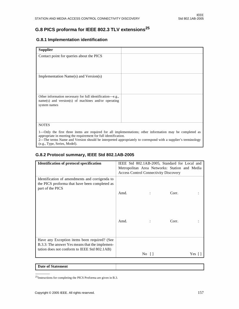
IEEESTATION AND MEDIA ACCESS CONTROL CONNECTIVITY DISCOVERY Std 802.1AB-2005
G.8 PICS proforma for IEEE 802.3 TLV extensions25
G.8.1 Implementation identification
Supplier
Contact point for queries about the PICS
Implementation Name(s) and Version(s)
Other information necessary for full identification—e.g.,name(s) and version(s) of machines and/or operatingsystem names
NOTES
1—Only the first three items are required for all implementations; other information may be completed asappropriate in meeting the requirement for full identification.2—The terms Name and Version should be interpreted appropriately to correspond with a supplier’s terminology(e.g., Type, Series, Model).
G.8.2 Protocol summary, IEEE Std 802.1AB-2005
Identification of protocol specification IEEE Std 802.1AB-2005, Standard for Local andMetropolitan Area Networks: Station and MediaAccess Control Connectivity Discovery
Identification of amendments and corrigenda tothe PICS proforma that have been completed aspart of the PICS
Amd. : Corr. :
Amd. : Corr. :
Have any Exception items been required? (SeeB.3.3: The answer Yes means that the implemen-tation does not conform to IEEE Std 802.1AB)
No [ ] Yes [ ]
Date of Statement
25Instructions for completing the PICS Proforma are given in B.3.
Copyright © 2005 IEEE. All rights reserved. 157
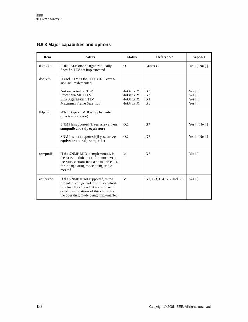
IEEEStd 802.1AB-2005
G.8.3 Major capabiities and options
Item Feature Status References Support
dot3xset Is the IEEE 802.3 Organizationally Specific TLV set implemented
O Annex G Yes [ ] No [ ]
dot3xtlv Is each TLV in the IEEE 802.3 exten-sion set implemented
Auto-negotiation TLV Power Via MDI TLVLink Aggregation TLVMaximum Frame Size TLV
dot3xtlv:M dot3xtlv:M dot3xtlv:M dot3xtlv:M
G.2 G.3 G.4 G.5
Yes [ ] Yes [ ] Yes [ ] Yes [ ]
lldpmib Which type of MIB is implemented (one is mandatory)
SNMP is supported (if yes, answer item snmpmib and skip equivstor)
SNMP is not supported (if yes, answer equivstor and skip snmpmib)
O.2
O.2
G.7
G.7
Yes [ ] No [ ]
Yes [ ] No [ ]
snmpmib If the SNMP MIB is implemented, is the MIB module in conformance with the MIB sections indicated in Table F-6 for the operating mode being imple-mented
M G.7 Yes [ ]
equivstor If the SNMP is not supported, is the provided storage and retieval capability functionally equivalent with the indi-cated specifications of this clause for the operating mode being implemented
M G.2, G.3, G.4, G.5, and G.6 Yes [ ]
158 Copyright © 2005 IEEE. All rights reserved.