Embed Size (px)
Citation preview
SA
ut the
COPYRIGHT InLicensed by COPYRIGHT InLicensed by
IEEE Std C37.20.1-1993(Revision of IEEE Std C37.20.1-1987)
IEEE Standard for Metal-Enclosed Low-Voltage Power Circuit Breaker Switchgear
SponsorSwitchgear Committeeof theIEEE Power Engineering Society
Approved September 15,1993
IEEE Standards Board
Abstract: Low-voltage metal-enclosed switchgear, which can contain either stationary or drawout,manually or electrically operated low-voltage ac or dc power circuit breakers in individual grounded metalcompartments, in three-pole, two-pole, or single-pole construction is covered. Rated maximum voltagelevels can be 254 V, 508 V, or 635 Vac and 300/325 V, 800 V, 1000 V, 1600 V, or 3200 Vdc. The continuouscurrent ratings of the main bus in ac designs can be 1600 Al 2000 A, 2500 A, 4000 A, 6000 A, 8000 A,10,000 A, or 12,000 A. The switchgear can also contain associated control, instruments, metering,protective, and regulating devices as necessary. The standard deals with service conditions, ratings,temperature limitations, and classification of insulating materials, insulation (dielectric) withstand voltagerequirements, test procedures, and application.Keywords: common related terms, control, cumulative loading, current transformers, drawout, indoor,instrumentation, load current-carrying, metering, outdoor, protection, qualifying terms, stationary
The Institute of Electrical and Electronics Engineers, Inc.345 East 47th Street, New York, NY 10017-2394, U
Copyright © 1994 by the Institute of Electrical and Electronics Engineers, Inc. All rights reserved.Published 1994. Printed in the United States of America.
ISBN 1-55937-378-4
No part of this publication may be reproduced in any form, in an electronic retrieval system or otherwise, withoprior written permission of the publisher
i
stitute of Electrical and Electronics Engineers, Inc.Information Handling Servicesstitute of Electrical and Electronics Engineers, Inc.Information Handling Services
ndardswithoutresent a
that have
no otherf the IEEEto changerd. Every is moreof some have the
ffiliationher with
relate tonitiateerests, it isis reason requests
te ofing toin all
COPYRIGHT InLicensed by COPYRIGHT InLicensed by
IEEE Standards documents are developed within the Technical Committees of the IEEE Societies and the StaCoordinating Committees of the IEEE Standards Board. Members of the committees serve voluntarily and compensation. They are not necessarily members of the Institute. The standards developed within IEEE repconsensus of the broad expertise on the subject within the Institute as well as those activities outside of IEEE expressed an interest in participating in the development of the standard.
Use of an IEEE Standard is wholly voluntary. The existence of an IEEE Standard does not imply that there are ways to produce, test, measure, purchase, market, or provide other goods and services related to the scope oStandard. Furthermore, the viewpoint expressed at the time a standard is approved and issued is subject brought about through developments in the state of the art and comments received from users of the standaIEEE Standard is subjected to review at least every five years for revision or reaffirmation. When a documentthan five years old and has not been reaffirmed, it is reasonable to conclude that its contents, although still value, do not wholly reflect the present state of the art. Users are cautioned to check to determine that theylatest edition of any IEEE Standard.
Comments for revision of IEEE Standards are welcome from any interested party, regardless of membership awith IEEE. Suggestions for changes in documents should be in the form of a proposed change of text, togetappropriate supporting comments.
Interpretations: Occasionally questions may arise regarding the meaning of portions of standards as they specific applications. When the need for interpretations is brought to the attention of IEEE, the Institute will iaction to prepare appropriate responses. Since IEEE Standards represent a consensus of all concerned intimportant to ensure that any interpretation has also received the concurrence of a balance of interests. For thIEEE and the members of its technical committees are not able to provide an instant response to interpretationexcept in those cases where the matter has previously received formal consideration.
Comments on standards and requests for interpretations should be addressed to:
Secretary, IEEE Standards Board445 Hoes LaneP.O. Box 1331Piscataway, NJ 08855-1331USA
IEEE standards documents may involve the use of patented technology. Their approval by the InstituElectrical and Electronics Engineers does not mean that using such technology for the purpose of conformsuch standards is authorized by the patent owner. It is the obligation of the user of such technology to obtanecessary permissions.
ii
stitute of Electrical and Electronics Engineers, Inc.Information Handling Servicesstitute of Electrical and Electronics Engineers, Inc.Information Handling Services
reaker
e original
r. Thesechgearcluded
bus.tchgearriate, thatce Test
blies
IEEE
-1970,cumentmmittee
lue to the
COPYRIGHT InLicensed by COPYRIGHT InLicensed by
Introduction
(This introduction is not a part of IEEE Std C37.20.1-1993, IEEE Standard for Metal-Enclosed Low-Voltage Power Circuit BSwitchgear.)
This standard has been revised to reflect needed technical changes that have been suggested since thdocument was published in 1987.
This standard includes the requirements for only metal-enclosed low-voltage power circuit breaker switchgearequirements were previously a part of IEEE Std C37.20-1969 (Reaff 1981), IEEE Standard for SwitAssemblies Including Metal-Enclosed Bus (1974 consolidated edition). Other types of equipment previously inin IEEE Std C37.20-1969 (Reaff 1981), will be incorporated in separate publications.
IEEE Std C37.20-1969 1 has for many years covered all switchgear assemblies, including metal-enclosedStandards committees of the IEEE Switchgear Assemblies Subcommittee and the NEMA Power SwiAssemblies Technical Committee recommended that the document be further developed and, where appropthe various sections be identified with their own standards. This approach also identifies with the ConformanProcedure Standards.
The IEEE Switchgear Assemblies Committee, in cooperation with the NEMA Power Switchgear AssemTechnical Committee, was responsible for this revision.
NEMA is responsible for developing clauses 4. and 6.. The Switchgear Assemblies Committee of theSwitchgear Committee is responsible for developing clauses 2., 3., 5., 7., and 8..
A Working Group of the NEMA Power Switchgear Assemblies Technical Committee revised IEEE Std C37.23IEEE Guide for Calculating Losses in Isolated-Phase Bus to include clause 8. of IEEE Std C37.20. The doupdates the material for metal-enclosed conductors including cable bus. The IEEE Switchgear Assemblies Corefined and expanded the document.
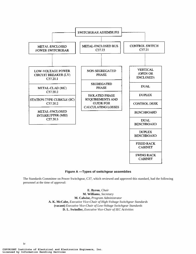
This publication is one of a series covering Switchgear Assemblies as follows (see figure A):
Through this joint effort over the many years, the switchgear assemblies standards have been of extreme vaindustry. Further suggestions for improvement gained in the use of this standard will be welcomed.
1IEEE Std C37.20-1969 has been withdrawn. This standard was delineated into the various branches of the IEEE Std C37.20 series.
IEEE Std C37.20.1-1993 Metal-Enclosed Low-Voltage Power Circuit Breaker Switchgear(1000 V and Below)
IEEE Std C27.20.2-1993 Metal-Clad and Station-Type Cubicle Switchgear (Above 1000 V)
IEEE Std C37.20.3-1987 Metal-Enclosed Interrupter Switchgear (Above 1000 V)
IEEE Std C37.21-1985 Control Switchboards
IEEE Std C37.23-1987 IEEE Standard for Metal-Enclosed Bus and Guide for Calculating Losses in Isolated Phase Bus
iii
stitute of Electrical and Electronics Engineers, Inc.Information Handling Servicesstitute of Electrical and Electronics Engineers, Inc.Information Handling Services
ollowing
COPYRIGHT InLicensed by COPYRIGHT InLicensed by
Figure A —Types of switchgear assemblies
The Standards Committee on Power Switchgear, C37, which reviewed and approved this standard, had the fpersonnel at the time of approval:
E. Byron, Chair M. Williams , Secretary
M. Calwise, Program AdministratorA. K. McCabe, Executive Vice-Chair of High-Voltage Switchgear Standards
(vacant) Executive Vice-Chair of Low-Voltage Switchgear StandardsD. L. Swindler, Executive Vice-Chair of IEC Activities
iv
stitute of Electrical and Electronics Engineers, Inc.Information Handling Servicesstitute of Electrical and Electronics Engineers, Inc.Information Handling Services
ved this
COPYRIGHT InLicensed by COPYRIGHT InLicensed by
The Switchgear Assemblies Subcommittee of the IEEE Switchgear Committee that prepared and approstandard had the following membership:
L. W. Gaussa, Sr., Chair
S. C. AtkinsonJ. A. BishopC. BallC. G. BurlandT. BurseE. R. Byron
P ClicknerJ. J. DravisJ. M. JerabekW. McCowanW. McKayW. E. Laubach
G. R. NourseG. O. PerkinsG. SakatsJ. C. ScottS. H. TelanderA. Tomeo
Organization Represented Name of Representative
Association of Iron and Steel Engineers (vacant)
Electric Light and Power Group M. C. MingoiaD. J. BorchartT. E. BruckJ. H. ProvanzanaJ. D. StewartG. R. Brandenberger (Alt.)A. K. McCabe (Alt.)
Institute of Electrical and Electronics Engineers D. F. PeeloL. B. BeardH. L. BowlesP. W. DwyerD. SignonS. C. Atkinson (Alt.)D. G. Kumbera (Alt.)L. V. McCall (Alt.)
Laubach Associates W. Laubach
National Electrical Manufacturers Association R. GarzonG. HaynesW. KrachtH. L. MillerT OlsonE. Byron (Alt.)G. T Jones (Alt.)G. Sakats (Alt.)S. Stone (Alt.)D. L. Swindler (Alt.)
Tennessee Valley Authority D. N. Reynolds
Testing Laboratory Group L. FrierW. T O’Grady
U.S. Department of the Army, Office of the Chief of Engineers J. A. Gilson
U.S. Department of the Interior, Bureau of Reclamation R. Arnold
U.S. Department of the Navy, Naval Construction Battalion Center R. L. Clark
Western Area Power Administration G. D. Birney
v
stitute of Electrical and Electronics Engineers, Inc.Information Handling Servicesstitute of Electrical and Electronics Engineers, Inc.Information Handling Services
rship:
COPYRIGHT InLicensed by COPYRIGHT InLicensed by
The following persons were on the balloting committee:
R. J. AltonJ. G. AngelisR. H. ArndtL. R. BeardH. L. BowlesM. T. BrownJ. H. BrunkeC. G. BurlandR. L. CapraA. DixonJ. J. DravisC. J. DvorakP. W. DwyerR. D. GarzonL. W. GaussaK. I. GrayK. D. HendrixH. L. HessW. F. HoenigmannJ. M. Jerabek
P. L. KolarikD. G. KumberaS. R. LambertD. M. LarsonW. E. LaubachJ. G. LeachG. N. LesterD. L. LottE. L. LuehringJ. A. ManeatisR. MatulicP. C. MayoA. K. McCabeL. V. McCallW. C. McKayH. W. MikuleckyD. C. MillsG. F. MontilletF. J. MuenchR. P. O’Leary
A. F. ParksD. F. PerkinsG. O. PerkinsR. RanjanJ. C. W. RansomJ. E. ReedA. B. RishworthH. C. RossL. R. SaavedraL. H. SchmidtC. A. SchwalbeG. St-JeanD. L. SwindlerS. H. TelanderF. C. TeufelE. F VeverkaC. L. WagnerW. R. WilsonB. F. Wirtz
When the IEEE Standards Board approved this standard on September 15, 1993, it had the following membe
Wallace S. Read, Chair Donald C. Loughry, Vice Chair
Andrew G. Salem, Secretary
Gilles A. BarilJosé A. Berrios de la PazClyde R. CampDonald C. FleckensteinJay Forster*David F. FranklinRamiro GarciaDonald N. Heirman
Jim IsaakBen C. JohnsonWalter J. KarplusLorraine C. KevraE. G. “Al” KienerIvor N. KnightJoseph L. Koepfinger*D. N. “Jim” Logothetis
Don T. Michael*Marco W. MigliaroL. John RankineArthur K. ReillyRonald H. ReimerGary S. RobinsonLeonard L. TrippDonald W. Zipse
*Member Emeritus
Also included are the following nonvoting IEEE Standards Board liaisons:
Satish K. AggarwalJames Beall
Richard B. EngelmanDavid E. Soffrin
Stanley I. Warshaw
Rochelle L. Stem IEEE Standards Project Editor
vi
stitute of Electrical and Electronics Engineers, Inc.Information Handling Servicesstitute of Electrical and Electronics Engineers, Inc.Information Handling Services
CLAUSE PAGE
..
COPYRIGHT InLicensed by COPYRIGHT InLicensed by
1. Scope and references...........................................................................................................................................1
1.1 Scope.......................................................................................................................................................... 11.2 References .................................................................................................................................................. 1
2. Definitions...........................................................................................................................................................3
2.1 General ....................................................................................................................................................... 32.2 Qualifying terms ........................................................................................................................................ 52.3 Common or related terms........................................................................................................................... 5
3. Service conditions ...............................................................................................................................................6
4. Ratings ................................................................................................................................................................7
4.1 General ....................................................................................................................................................... 74.2 Voltage and insulation levels ..................................................................................................................... 84.3 Rated frequency ......................................................................................................................................... 84.4 Rated current .............................................................................................................................................. 84.5 Temperature limitations ............................................................................................................................. 94.6 Current transformer ratings...................................................................................................................... 114.7 Current transformer accuracies ................................................................................................................ 11
5. Tests ..................................................................................................................................................................12
5.1 General ..................................................................................................................................................... 125.2 Design tests .............................................................................................................................................. 125.3 Production tests ........................................................................................................................................ 195.4 Conformance tests.................................................................................................................................... 205.5 Field dielectric tests ................................................................................................................................. 20
6. Construction ......................................................................................................................................................20
6.1 General requirements ............................................................................................................................... 206.2 Materials and finish.................................................................................................................................. 266.3 Barriers..................................................................................................................................................... 266.4 Buses and connections ............................................................................................................................. 276.5 Access doors and covers .......................................................................................................................... 276.6 Closing and tripping................................................................................................................................. 276.7 Indoor LV switchgear .............................................................................................................................. 276.8 Outdoor LV switchgear............................................................................................................................ 276.9 Pull box .................................................................................................................................................... 286.10 Arrangements with stationary circuit breakers ........................................................................................ 286.11 Arrangements with drawout circuit breakers ........................................................................................... 286.12 Primary cable space ................................................................................................................................. 296.13 Precautionary labels ................................................................................................................................. 306.14 Lifting devices.......................................................................................................................................... 30
7. Application guide for LV switchgear................................................................................................................30
7.1 Unusual service conditions ...................................................................................................................... 307.2 System characteristics—Voltage and frequency.................................................................................... 33
vii
stitute of Electrical and Electronics Engineers, Inc.Information Handling Servicesstitute of Electrical and Electronics Engineers, Inc.Information Handling Services
CLAUSE PAGE
...... 42
COPYRIGHT InLicensed by COPYRIGHT InLicensed by
7.3 Overvoltage considerations—Insulation levels ....................................................................................... 337.4 Continuous current rating and overload capability .................................................................................. 347.5 Short-circuit considerations ..................................................................................................................... 407.6 Nuclear power plant application .............................................................................................................. 407.7 Associated devices often used in LV switchgear..................................................................................... 407.8 Protection and isolation of switchgear connected to other circuit protective equipment ..................7.9 Overcurrent protection ............................................................................................................................. 42
8. Guide for handling, storage, and installation ....................................................................................................42
8.1 General ..................................................................................................................................................... 428.2 Handling................................................................................................................................................... 428.3 Preoperation check................................................................................................................................... 448.4 Removable elements ................................................................................................................................ 448.5 Interlocks.................................................................................................................................................. 448.6 Energizing ................................................................................................................................................ 45
viii
stitute of Electrical and Electronics Engineers, Inc.Information Handling Servicesstitute of Electrical and Electronics Engineers, Inc.Information Handling Services
but notitches,
includesndustrialn board
r ac LV
in this
lication
COPYRIGHT InLicensed by COPYRIGHT InLicensed by
IEEE Standard for Metal-Enclosed Low-Voltage Power Circuit Breaker Switchgear
1. Scope and references
1.1 Scope
This standard covers metal-enclosed low-voltage power circuit breaker switchgear assemblies containing,limited to, such devices as low-voltage power circuit breakers (fused or unfused); other interrupting devices; swcontrol, instrumentation, and metering; and protective and regulating equipment.
This standard is concerned with enclosed, rather than open, indoor and outdoor switchgear assemblies. Ittypes of equipment that are part of secondary unit substations. It does not apply to equipment covered by icontrol standards, communication switchboards, communication switching equipment, switchboards for use oships, or dead-front distribution switchboards.
In this standard, metal-enclosed low-voltage power circuit breaker switchgear shall be called LV switchgear. Foswitchgear, the voltage shall be 1000 V or below; for dc LV switchgear, the voltage shall be 3200 V or below.
1.2 References
This standard shall be used in conjunction with the following publications. When the standards referenceddocument are superseded by an approved revision, the revision shall apply.
Accredited Standards Committee C2-1993, National Electrical Safety Code (NESC).1
ANSI C37.16-1988, American National Standard Preferred Ratings, Related Requirements and AppRecommendations for Low-Voltage Power Circuit Breakers and AC Power Circuit Protectors.2
1The NESC is available from the Institute of Electrical and Electronics Engineers, 445 Hoes Lane, P.O. Box 1331, Piscataway, NJ 08855-1331,USA.2ANSI publications are available from the Sales Department, American National Standards Institute, 11 West 42nd Street, 13th Floor, New York,NY 10036, USA.
1
stitute of Electrical and Electronics Engineers, Inc.Information Handling Servicesstitute of Electrical and Electronics Engineers, Inc.Information Handling Services
IEEE Std C37.20.1-1993 LOW-VOLTAGE POWER CIRCUIT BREAKER SWITCHGEAR
ircuit
orrosive
nt and
Red
s (IEEE
E Gray
ial and
uclear
trial and
COPYRIGHT InLicensed by COPYRIGHT InLicensed by
ANSI C37.51-1989, American National Standard for Switchgear—Metal-Enclosed Low-Voltage AC Power CBreaker Switchgear Assemblies—Conformance Test Procedures.
ANSI/NFPA 70-1993, National Electrical Code.3
ANSI/UL 486A-1991, Wire Connectors and Soldering Lugs for Use With Copper Conductors.4
ANSI Z535.4-1991, American National Standard for Product Safety Signs and Labels.
ASTM B117-90, Standard Method of Salt Spray (Fog) Testing.5
ASTM D229-91, Standard Method of Testing Rigid Sheet and Plate Materials Used for Electrical Insulation.
ASTM D714-87, Standard Method for Evaluating Degree of Blistering of Paints.
ASTM D1535-89, Standard Method of Specifying Color by the Munsell System.
ASTM D1654-79a (R 1984), Standard Method for Evaluation of Painted or Coated Specimens Subjected to CEnvironments.
ASTM G21-90, Standard Practice for Determining Resistance of Synthetic Polymeric Materials to Fungi.
IEEE Std 1-1986, IEEE Standard General Principles for Temperature Limits in the Rating of Electric Equipmefor the Evaluation of Electrical Insulation (ANSI).6
IEEE Std 4-1978, IEEE Standard Techniques for High-Voltage Testing (ANSI).
IEEE Std 100-1992, The New IEEE Standard Dictionary of Electrical and Electronics Terms (ANSI).
IEEE Std 141-1993, IEEE Recommended Practice for Electric Power Distribution for Industrial Plants (IEEEBook).
IEEE Std 142-1991, IEEE Recommended Practice for Grounding of Industrial and Commercial Power SystemGreen Book) (ANSI).
IEEE Std 241-1990, IEEE Recommended Practice for Electric Power Systems in Commercial Buildings (IEEBook) (ANSI).
IEEE Std 242-1986 (Reaff 1991), IEEE Recommended Practice for Protection and Coordination of IndustrCommercial Power Systems (IEEE Buff Book) (ANSI).
IEEE Std 344-1987, IEEE Recommended Practices for Seismic Qualification of Class 1E Equipment for NPower Generating Stations (ANSI).
IEEE Std 446-1987, IEEE Recommended Practice for Emergency and Standby Power Systems for IndusCommercial Applications (IEEE Orange Book) (ANSI).
3The National Electrical Code is published by the National Fire Protection Association, Batterymarch Park, Quincy, MA 02269. Copies are alsoavailable from the Sales Department, American National Standards Institute, 11 West 42nd Street, 13th Floor, New York, NY 10036, USA.4ANSI/UL publications are available from Underwriters Laboratories Inc., Publication Stock, 333 Pfingsten Road, Northbrook, IL 60062. Copiesare also available from the Sales Department, American National Standards Institute, 11 West 42nd Street, 13th Floor, New York, NY 10036, USA.5ASTM publications are available from American Society for Testing and Materials, 1916 Race St, Philadelphia, PA 19103, USA.61EEE publications are available from the Institute of Electrical and Electronics Engineers, 445 Hoes Lane, PO Box 1331, Piscataway, NJ 08855-1331, USA.
2 Copyright © 1998 IEEE All Rights Reserved
stitute of Electrical and Electronics Engineers, Inc.Information Handling Servicesstitute of Electrical and Electronics Engineers, Inc.Information Handling Services
IEEE STANDARD FOR METAL-ENCLOSED IEEE Std C37.20.1-1993
ated on
I).
I).
etal-
oltage
d Relay
diated
ion of
n and
intendedrd.
ger (†)
unding a
COPYRIGHT InLicensed by COPYRIGHT InLicensed by
IEEE Std C37.09-1979 (Reaff 1988), IEEE Standard Test Procedures for AC High-Voltage Circuit Breakers Ra Symmetrical Current Basis (ANSI).
IEEE Std C37.2-1991, IEEE Standard Electrical Power System Device Function Numbers (ANSI).
IEEE Std C37.13-1990, IEEE Standard for Low-Voltage AC Power Circuit Breakers Used in Enclosures (ANS
IEEE Std C37.14-1992, IEEE Standard for Low-Voltage DC Power Circuit Breakers Used in Enclosures (ANS
IEEE Std C37.24-1986 (Reaff 1991), IEEE Guide for Evaluating the Effect of Solar Radiation on Outdoor MEnclosed Switchgear (ANSI).
IEEE Std C37.26-1972 (Reaff 1976), IEEE Guide for Methods of Power-Factor Measurement for Low-VInductive Test Circuits (ANSI).
IEEE Std C37.100-1992, IEEE Standard Definitions for Power Switchgear.
IEEE Std C37.90.1-1989, IEEE Standard Surge Withstand Capability (SWC) Tests for Protective Relays anSystems (ANSI).
IEEE Std C37.90.2-1987, IEEE Trial-Use Standard Withstand Capability of Relay Systems to RaElectromagnetic Interference from Transceivers (ANSI).
IEEE Std C57.13-1978 (Reaff 1986), IEEE Standard Requirements for Instrument Transformers (ANSI).
NEMA CC1-1993, Electric Power Connectors for Substations.7
NEMA WC5-1992/ICEA S-61-402, Thermoplastic-Insulated Wire and Cable for the Transmission and DistributElectrical Energy.
NEMA WC7-1991/ICEA S-66-524, Cross-Linked Polyethylene-Insulated Wire and Cable for the TransmissioDistribution of Electrical Energy.
2. Definitions
The definitions of terms contained in this standard, or in other standards referred to in this standard, are not to embrace all legitimate meanings of the terms. They are applicable only to the subject treated in this standa
If a term is not defined in this standard, the definition in IEEE Std C37.100-1992 8 applies. An asterisk(*) following adefinition indicates that the definition in this standard is not contained in IEEE Std C37.100-1992 while a dagindicates the definition differs from that in IEEE Std C37.100-1992 .
2.1 General
2.1.1 ambient air temperature: The temperature of the surrounding air that comes in contact with equipment.
NOTE — Ambient air temperature, as applied to enclosed switchgear assemblies, is the average temperature of the surroirthat comes in contact with the enclosure. (See 5.2.2.3 for method of measurement.)
7NEMA publications are available from the National Electrical Manufacturers Association, 2101 L Street, NW, Washington, DC 20037, USA.8Information on references can be found in 1.2.
Copyright © 1998 IEEE All Rights Reserved 3
stitute of Electrical and Electronics Engineers, Inc.Information Handling Servicesstitute of Electrical and Electronics Engineers, Inc.Information Handling Services
IEEE Std C37.20.1-1993 LOW-VOLTAGE POWER CIRCUIT BREAKER SWITCHGEAR
iliary
d the
men is
) beyo
, style,r normalplicable
alculationsts are not of theses not beenate. Once
trolledt) type;
withing or
devices.
mples,ons and
plann
iatedsociatederation,
COPYRIGHT InLicensed by COPYRIGHT InLicensed by
2.1.2 auxiliary compartment: That portion of the switchgear assembly that is assigned to the housing of auxequipment, such as potential transformers, control power transformers, or other miscellaneous devices.*
2.1.3 circuit breaker compartment: That portion of a switchgear assembly that contains one circuit breaker anassociated primary conductors and secondary control connection devices including current transformers.*
2.1.4 conformance tests: Tests that demonstrate compliance with the applicable standards. The test specinormally subjected to all planned production tests prior to initiation of the conformance test program.†
NOTE — The conformance tests may, or may not, be similar to certain design tests. Demonstration of margin (capabilitiesndthe standards is not required.
2.1.5 design tests: Tests made by the manufacturer to determine the adequacy of the design of a particular typeor model of equipment or its component parts to meet its assigned ratings and to operate satisfactorily undeservice conditions or under special conditions if specified, and may be used to demonstrate compliance with apstandards of the industry.†
NOTES:
1 — Design tests are made on representative apparatuses or prototypes to verify the validity of design analyses and cmethods and to substantiate the ratings assigned to all other apparatuses of basically the same design. These teintended to be made on every design variation or to be used as part of normal production. The applicable portiondesign tests may also be used to evaluate modifications of a previous design and to ensure that performance haadversely affected. Test data from previous similar designs may also be used for current designs, where approprimade, the tests need not be repeated unless the design is changed so as to modify performance.
2 — Design tests are sometimes called type tests.
2.1.6 field tests: Tests made after the switchgear assembly has been installed at its place of utilization.
2.1.7 metal-enclosed low-voltage power circuit-breaker switchgear (LV): LV switchgear of multiple or individualenclosures, including the following equipment as required:
a) Low-voltage power circuit breakers (fused or unfused) in accordance with IEEE Std C37.13-1990 .†b) Bare bus and connectionsc) Instrument and control power transformersd) Instruments, meters, and relayse) Control wiring and accessory devices
The low-voltage power circuit breakers are contained in individual grounded metal compartments and coneither remotely or from the front of the enclosure. The circuit breakers may be stationary or removable (drawouwhen of removable type, mechanical interlocks are provided for proper operating sequence.†
2.1.8 metal-enclosed power switchgear (ME): A switchgear assembly completely enclosed on all sides and top sheet metal (except for ventilating openings and inspection windows) containing primary power circuit switchinterrupting devices, or both, with buses and connections. The assembly may include control and auxiliary Access to the interior of the enclosure is provided by doors or removable covers, or both.†
2.1.9 production tests: Tests made for quality control by the manufacturer on every device or representative saor on parts or materials as required to verify during production that the product meets the design specificatiapplicable standards.†
NOTES:
1 — Certain quality assurance tests on identified critical parts of repetitive high-production devices may be tested on aedstatistical sampling basis.
2 — Production tests are sometimes called routine tests.
2.1.10 switchgear: A general term covering switching and interrupting devices and their combination with assoccontrol, instruments, metering, protective, and regulating devices; also assemblies of these devices with asinterconnections, accessories, and supporting structures used primarily in connection with the gentransmission, distribution, and conversion of electric power.†
4 Copyright © 1998 IEEE All Rights Reserved
stitute of Electrical and Electronics Engineers, Inc.Information Handling Servicesstitute of Electrical and Electronics Engineers, Inc.Information Handling Services
IEEE STANDARD FOR METAL-ENCLOSED IEEE Std C37.20.1-1993
r)ation,uctors,
s, and
td 100-
s given
to the
COPYRIGHT InLicensed by COPYRIGHT InLicensed by
2.1.11 switchgear assembly (see figure A in the introduction): An assembled equipment (indoor or outdooincluding, but not limited to, one or more of the following categories: switching, interrupting, control, instrumentmetering, protective, and regulating devices; together with their supporting structures, enclosures, condelectrical interconnections, and accessories.†
2.1.12 vertical section: That portion of the switchgear assembly between two successive vertical delineationmay contain one or more circuit breakers, auxiliary compartments, and associated primary conductors.†
2.2 Qualifying terms
The following qualifying terms relating to types of enclosures, ventilation methods, etc., are defined in IEEE S1992 and the user is referred to the definitions given therein:
2.2.1 accessible (as applied to equipment):
2.2.2 alive (live):
2.2.3 automatic (self-coupling):
2.2.4 dead front:
2.2.5 enclosed (inclosed):
2.2.6 enclosed ventilated apparatus:
2.2.7 insulated:
2.2.8 insulating:
2.2.9 isolated:
2.2.10 manual:
2.2.11 ventilated:
The following qualifying terms are defined in IEEE Std C37.100-1992 and the user is referred to the definitiontherein:
2.2.12 electrical:
2.2.13 enclosure:
2.2.14 flame-resistant (retardant):
2.2.15 general-purpose enclosure:
2.2.16 indoor:
2.2.17 metal-enclosed:
2.2.18 outdoor:
2.2.19 resistant (used as a suffix):
2.2.20 secondary (used as an adjective):
2.2.21 ventilated enclosure:
2.3 Common or related terms
The following common or related terms are defined in IEEE Std C37.100-1992 and the user is referreddefinitions given therein:
Copyright © 1998 IEEE All Rights Reserved 5
stitute of Electrical and Electronics Engineers, Inc.Information Handling Servicesstitute of Electrical and Electronics Engineers, Inc.Information Handling Services
IEEE Std C37.20.1-1993 LOW-VOLTAGE POWER CIRCUIT BREAKER SWITCHGEAR
ed below.d in this
tchgear
e used
COPYRIGHT InLicensed by COPYRIGHT InLicensed by
2.3.1 asymmetrical:
2.3.2 auxiliary switches:
2.3.3 barrier:
2.3.4 bus:
2.3.5 connected position (of a switchgear assembly removable element):
2.3.6 continuous current tests:
2.3.7 current limiting fuse:
2.3.8 disconnected position (of a switchgear assembly removable element):
2.3.9 drawout-mounted device:
2.3.10 ground bus:
2.3.11 live parts:
2.3.12 main (primary) switchgear connections:
2.3.13 mimic bus:
2.3.14 normal frequency:
2.3.15 primary disconnecting devices (of a switchgear assembly):
2.3.16 removable element (of a switchgear assembly):
2.3.17 secondary and control wiring (small wiring):
2.3.18 secondary disconnecting contacts:
2.3.19 silver surfaced or equivalent:
2.3.20 stationary-mounted device:
2.3.21 symmetrical:
2.3.22 terminal (terminal connector):
2.3.23 terminal block (terminal board):
2.3.24 test position:
3. Service conditions
Standards for the design and performance of LV switchgear are based on usual service conditions as describThe selection of equipment for a particular application can be based on the construction and ratings as definestandard provided that the following usual service conditions exist:
a) The temperature of the cooling air (ambient air temperature) surrounding the enclosure of the LV swiis within the limits of −30 °C and +40 °C.
b) The altitude of the installation does not exceed 6600 ft (2000 m).c) The effect of solar radiation is not significant. (The principles stated in IEEE Std C37.24-1986 may b
for guidance.)d) Unusual service conditions, such as those outlined in 7.1, do not prevail.
6 Copyright © 1998 IEEE All Rights Reserved
stitute of Electrical and Electronics Engineers, Inc.Information Handling Servicesstitute of Electrical and Electronics Engineers, Inc.Information Handling Services
IEEE STANDARD FOR METAL-ENCLOSED IEEE Std C37.20.1-1993
mbientecondary
e ratings,s of thespecific
COPYRIGHT InLicensed by COPYRIGHT InLicensed by
4. Ratings
4.1 General
The ratings of a switchgear assembly are designations of operating limits under specified conditions of atemperature, temperature rise, etc. Where the switchgear assembly comprises a combination of primary and scircuits, each may be given ratings.
LV switchgear shall have the following ratings:
a) Rated maximum voltageb) Rated frequencyc) Rated insulation leveld) Rated continuous currente) Rated short-time currentf) Rated short-circuit current
The designated ratings in this standard are preferred but are not considered to be restrictive. In addition to thesa switchgear assembly may have interrupting or switching capabilities, which are determined by the ratingparticular interrupting and switching devices that are integral parts of the switchgear assembly. Refer to standards for the ratings of these devices.
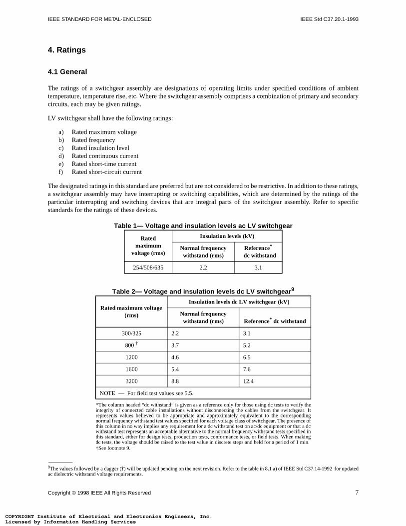
Table 1— Voltage and insulation levels ac LV switchgear
Table 2— Voltage and insulation levels dc LV switchgear 9
Rated maximum
voltage (rms)
Insulation levels (kV)
Normal frequency withstand (rms)
Reference*
dc withstand
254/508/635 2.2 3.1
Rated maximum voltage (rms)
Insulation levels dc LV switchgear (kV)
Normal frequency withstand (rms) Reference* dc withstand
*The column headed “dc withstand” is given as a reference only for those using dc tests to verify theintegrity of connected cable installations without disconnecting the cables from the switchgear. Itrepresents values believed to be appropriate and approximately equivalent to the correspondingnormal frequency withstand test values specified for each voltage class of switchgear. The presence ofthis column in no way implies any requirement for a dc withstand test on ac/dc equipment or that a dcwithstand test represents an acceptable alternative to the normal frequency withstand tests specified inthis standard, either for design tests, production tests, conformance tests, or field tests. When makingdc tests, the voltage should be raised to the test value in discrete steps and held for a period of 1 min.
300/325 2.2 3.1
800 †
†See footnote 9.
3.7 5.2
1200 4.6 6.5
1600 5.4 7.6
3200 8.8 12.4
NOTE — For field test values see 5.5.
9The values followed by a dagger (†) will be updated pending on the next revision. Refer to the table in 8.1 a) of IEEE Std C37.14-1992 for updatedac dielectric withstand voltage requirements.
Copyright © 1998 IEEE All Rights Reserved 7
stitute of Electrical and Electronics Engineers, Inc.Information Handling Servicesstitute of Electrical and Electronics Engineers, Inc.Information Handling Services
IEEE Std C37.20.1-1993 LOW-VOLTAGE POWER CIRCUIT BREAKER SWITCHGEAR
, and is
erform.
r direct without
0 A, or000 A,
r circuit circuitbut in no
rrent atated by
COPYRIGHT InLicensed by COPYRIGHT InLicensed by
4.2 Voltage and insulation levels
4.2.1 Rated maximum voltage
The rated maximum voltage of LV switchgear is the highest rms voltage for which the equipment is designedthe upper limit for operation.
4.2.2 Rated insulation level
The rated insulation level of LV switchgear is equal to the normal frequency one-minute withstand voltage.
4.2.3 Voltage and insulation levels for ac LV switchgear
The rated maximum voltages and corresponding insulation levels for ac LV switchgear are listed in table 1.
4.2.4 Voltage and insulation level for dc LV switchgear
The rated maximum voltages and corresponding insulation levels for dc LV switchgear are listed in table 2.
4.3 Rated frequency
The rated frequency of a device, or an assembly, is the frequency of the circuit at which it is designed to p(Ratings for ac equipment are based on a frequency of 60 Hz.)
4.4 Rated current
4.4.1 Rated continuous current
The rated continuous current of LV switchgear is the maximum current in rms amperes at rated frequency ocurrent that can be carried continuously by the primary circuit components, including buses and connections,causing temperatures in excess of specified limits for the following:
a) Any primary or secondary circuit componentb) Any insulating medium, or structural or enclosing member
The specified temperature limits applicable to switchgear assemblies are given in 4.5.1 through 4.5.6.
4.4.2 Continuous current ratings
The preferred continuous current ratings of the main bus in ac LV switchgear are 1600 A, 2000 A, 3000 A, 3204000 A. In dc LV switchgear the preferred continuous current ratings are 1600 A, 2000 A, 2500 A, 4000 A, 56000 A, 8000 A, 10,000 A, and 12,000 A.
The continuous current rating of the vertical section bus riser shall be equal to the frame size of the ac LV powebreaker used (see ANSI C37.16-1988 ) except as modified by the allowable cumulative loading of multiple acbreakers in the same section (see table 13), or by lower continuous current ratings for current transformers, case does it need to be greater than the rating of the main bus.
4.4.3 Rated short-time current
The rated short-time current of a LV switchgear assembly is the designated limit of available (prospective) cuwhich it shall be required to withstand its short-time current duty cycle (two periods of 1/2 s current flow, separ
8 Copyright © 1998 IEEE All Rights Reserved
stitute of Electrical and Electronics Engineers, Inc.Information Handling Servicesstitute of Electrical and Electronics Engineers, Inc.Information Handling Services
IEEE STANDARD FOR METAL-ENCLOSED IEEE Std C37.20.1-1993
xpressedalf cycle
currentater (X/ort-time
at ratedis underfrom the
t ratinger factor
vered in
evices
3 for the
ith their when the
COPYRIGHT InLicensed by COPYRIGHT InLicensed by
a 15 s interval of zero current) at rated maximum voltage under the prescribed test conditions. This current is ein rms symmetrical amperes and is measured from the envelope of the available current wave at a time one-hafter current is established. This current also demonstrates the dc short-time current ratings.
LV switchgear assemblies shall be capable of withstanding the short-time current duty cycle with all degrees ofasymmetry produced by three-phase or single-phase circuits having a short-circuit power factor of 15% or greR ratio 6.6 or less). LV switchgear assemblies shall have preferred short-time current ratings equal to the shcurrent rating of the smallest frame size circuit breaker used in the assembly as listed in ANSI C37.16-1988.
4.4.4 Rated short-circuit current
The rated short-circuit current of an LV ac assembly is the designated limit of available (prospective) current maximum voltage that it shall be required to withstand for a period of no less than four cycles on a 60 Hz basthe prescribed test conditions. This current is expressed in rms symmetrical amperes and is measured envelope of the available current wave at a time 1/2 cycle after current is established.
AC LV switchgear assemblies shall have preferred short-circuit current ratings equal to the short-circuit currenof the smallest frame size circuit breaker used in the assembly as covered in ANSI C37.16-1988. Use pow(X/R ratio) identical to that of 4.4.3 for this test.
DC LV switchgear shall meet the ratings and test parameters required for LV dc power circuit breakers as coIEEE Std C37.14-1992 and ANSI C37.16-1988.
4.5 Temperature limitations
4.5.1 Limiting temperature
The limiting temperature for LV switchgear is the maximum temperature permitted for the following:
a) Any component such as insulation, buses, instrument transformers, and switching and interrupting db) Air in cable termination compartmentsc) Any non-current-carrying structural partsd) Air-surrounding devices
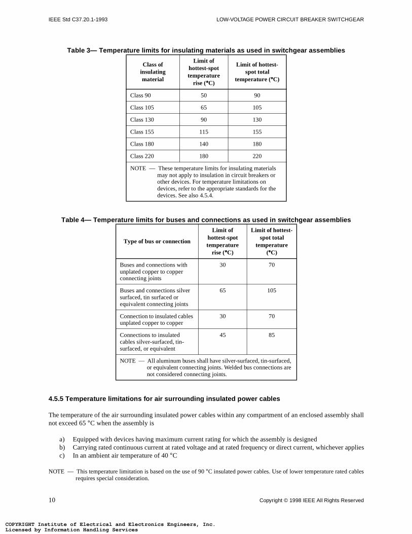
4.5.2 Temperature limits for insulating materials
The total temperature to which insulating materials are subjected shall not exceed the values listed in table various classes of insulating materials.
4.5.3 Temperature limits for buses and connections
The total temperature of buses and connections shall not exceed the values listed in table 4.
4.5.4 Temperature limitations for air surrounding devices within an enclosed assembly
The temperature of the air surrounding all devices within an enclosed assembly, considered in conjunction wrating and loading as used, shall not cause these devices to operate outside their rated temperature rangeenclosure of the assembly is surrounded by air within an ambient temperature range of −30 °C to +40 °C.
Copyright © 1998 IEEE All Rights Reserved 9
stitute of Electrical and Electronics Engineers, Inc.Information Handling Servicesstitute of Electrical and Electronics Engineers, Inc.Information Handling Services
IEEE Std C37.20.1-1993 LOW-VOLTAGE POWER CIRCUIT BREAKER SWITCHGEAR
bly shall
applies
bles
COPYRIGHT InLicensed by COPYRIGHT InLicensed by
Table 3— Temperature limits for insulating materials as used in switchgear assemblies
Table 4— Temperature limits for buses and connections as used in switchgear assemblies
4.5.5 Temperature limitations for air surrounding insulated power cables
The temperature of the air surrounding insulated power cables within any compartment of an enclosed assemnot exceed 65 °C when the assembly is
a) Equipped with devices having maximum current rating for which the assembly is designedb) Carrying rated continuous current at rated voltage and at rated frequency or direct current, whicheverc) In an ambient air temperature of 40 °C
NOTE — This temperature limitation is based on the use of 90 °C insulated power cables. Use of lower temperature rated carequires special consideration.
Class of insulating material
Limit of hottest-spot temperature
rise (°°°°C)
Limit of hottest-spot total
temperature (°°°°C)
Class 90 50 90
Class 105 65 105
Class 130 90 130
Class 155 115 155
Class 180 140 180
Class 220 180 220
NOTE — These temperature limits for insulating materials may not apply to insulation in circuit breakers or other devices. For temperature limitations on devices, refer to the appropriate standards for the devices. See also 4.5.4.
Type of bus or connection
Limit of hottest-spot temperature
rise (°°°°C)
Limit of hottest-spot total
temperature (°°°°C)
Buses and connections with unplated copper to copper connecting joints
30 70
Buses and connections silver surfaced, tin surfaced or equivalent connecting joints
65 105
Connection to insulated cables unplated copper to copper
30 70
Connections to insulated cables silver-surfaced, tin-surfaced, or equivalent
45 85
NOTE — All aluminum buses shall have silver-surfaced, tin-surfaced, or equivalent connecting joints. Welded bus connections are not considered connecting joints.
10 Copyright © 1998 IEEE All Rights Reserved
stitute of Electrical and Electronics Engineers, Inc.Information Handling Servicesstitute of Electrical and Electronics Engineers, Inc.Information Handling Services
IEEE STANDARD FOR METAL-ENCLOSED IEEE Std C37.20.1-1993
er total
her total
o higher
t-circuitted byt of thee short-
currenturrent-
dered as
if highercies may
le 5.
COPYRIGHT InLicensed by COPYRIGHT InLicensed by
4.5.6 Temperature limitations for external parts subject to contact by personnel
a) External parts handled by the operator in the normal course of his or her duties shall have no hightemperature than 50 °C.
b) External surfaces accessible to an operator in the normal course of his or her duties shall have no higtemperature than 70 °C.
c) External surfaces not accessible to an operator in the normal course of his or her duties shall have ntotal temperature than 110 °C.
NOTE — For additional information on temperature limits, see IEEE Std 1-1986.
4.6 Current transformer ratings
4.6.1 Current transformer mechanical ratings
The mechanical ratings of current transformers shall be such that they will successfully withstand the shorcurrent for which the associated circuit-interrupting devices are applied. When the primary circuit is proteccurrent-limiting fuses, the current transformers shall successfully withstand the maximum let-through currenfuses. Unless specifically limited to a shorter time by the associated protective equipment, the duration of thcircuit shall be considered as being four cycles.
4.6.2 Current transformer thermal ratings
The thermal ratings of current transformers shall be such that they will successfully withstand the short-circuitfor which the associated circuit-interrupting devices are applied. When the primary circuit is protected by climiting fuses, the current transformers shall successfully withstand the maximum I2t of the fuses. Unless specificallylimited to a shorter time by the associated protective equipment, the duration of the short circuit shall be consibeing 1 s.
4.6.3 Current transformer ambient temperature
Current transformers for use in switchgear assemblies shall be rated on the basis of at least 55 °C ambient temperaturein accordance with 4.1.1.2 in IEEE Std C57.13-1978.
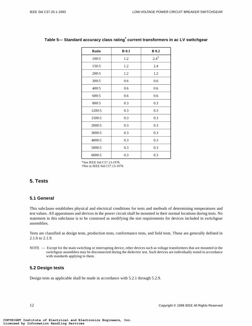
4.7 Current transformer accuracies
Accuracies tabulated hereafter are the minimum that shall be supplied. The manufacturer should be consultedaccuracies are required by the purchaser. It should be recognized that current transformers with higher accuranot meet the requirements of 4.6.1 and 4.6.2.
For installation in ac LV switchgear, the standard current transformer accuracies for metering are listed in tab
Copyright © 1998 IEEE All Rights Reserved 11
stitute of Electrical and Electronics Engineers, Inc.Information Handling Servicesstitute of Electrical and Electronics Engineers, Inc.Information Handling Services
IEEE Std C37.20.1-1993 LOW-VOLTAGE POWER CIRCUIT BREAKER SWITCHGEAR
tures andests. Noitchgear
defined in
ed in tcordance
COPYRIGHT InLicensed by COPYRIGHT InLicensed by
5. Tests
5.1 General
This subclause establishes physical and electrical conditions for tests and methods of determining temperatest values. All apparatuses and devices in the power circuit shall be mounted in their normal locations during tstatement in this subclause is to be construed as modifying the test requirements for devices included in swassemblies.
Tests are classified as design tests, production tests, conformance tests, and field tests. These are generally2.1.6 to 2.1.9.
NOTE — Except for the main switching or interrupting device, other devices such as voltage transformers that are mountheswitchgear assemblies may be disconnected during the dielectric test. Such devices are individually tested in acwith standards applying to them.
5.2 Design tests
Design tests as applicable shall be made in accordance with 5.2.1 through 5.2.9.
Table 5— Standard accuracy class rating * current transformers in ac LV switchgear
*See IEEE Std C57.13-1978.
Ratio B 0.1 B 0.2
100:5 1.2 2.4†
†Not in IEEE Std C57.13-1978.
150:5 1.2 2.4
200:5 1.2 1.2
300:5 0.6 0.6
400:5 0.6 0.6
600:5 0.6 0.6
800:5 0.3 0.3
1200:5 0.3 0.3
1500:5 0.3 0.3
2000:5 0.3 0.3
3000:5 0.3 0.3
4000:5 0.3 0.3
5000:5 0.3 0.3
6000:5 0.3 0.3
12 Copyright © 1998 IEEE All Rights Reserved
stitute of Electrical and Electronics Engineers, Inc.Information Handling Servicesstitute of Electrical and Electronics Engineers, Inc.Information Handling Services
IEEE STANDARD FOR METAL-ENCLOSED IEEE Std C37.20.1-1993
ulationnce with0 s and
imes thetchgearoltmeterth tableser:
ovable
idually
e frame
tgoing frame
st shall
icable, beot exceed
t positdoes not must be
ear).
various be made
COPYRIGHT InLicensed by COPYRIGHT InLicensed by
5.2.1 Dielectric tests
Normal frequency withstand tests on LV switchgear shall be performed to demonstrate the ability of the inssystem to withstand the voltages in accordance with tables 1 and 2. All voltages shall be measured in accordaIEEE Std 4-1978. The voltage is to be increased gradually from zero to the required test value within 5 s to 1shall be held at that value for 1 min.
The ac test voltages shall be essentially sinusoidal and applied with a minimum crest value equal to 1.414 tspecified values. The frequency of the test voltage shall be within +20% of the rated frequency of the LV swior ± 20% of 60 Hz for dc switchgear being tested. If a test transformer of less than 500 VA is used, a suitable vshall be provided to measure the applied output voltage directly. The applicable test voltage in accordance wi1 and 2, shall be applied for a period of I min to the primary circuit of the LV switchgear in the following mann
a) For equipment with stationary devices and for equipment with drawout-mounted devices with the remelements in the connected position, apply the test voltage as follows:1) With the circuit breaker contacts closed, between each phase of the switchgear assembly indiv
with the frame and the other phases and the neutral bus grounded2) With the circuit breaker contacts open, between each terminal of the switchgear assembly with th
and all other terminals groundedb) With the drawout circuit breaker in the test position and closed, apply the test voltage as follows:
1) Simultaneously to all the incoming terminals of the switchgear assembly with the frame and outerminals grounded. Repeat tests by applying the test voltage to the outgoing terminals with theand incoming terminals grounded.
2) Simultaneously between all incoming and outgoing terminals of the switchgear assembly. This tebe made with a value of voltage 10% higher than that specified in tables 1 and 2.
NOTES:
1 — For the test across the open gap at 10% higher voltage, an intermediate point of the voltage source may, if practconnected to ground and to the frame of the assembly so that the voltage between any live part and the frame will nthat specified in table 1. If this is not practicable, the frame may be insulated from ground.
2 — Successful completion of these tests does not necessarily provide assurance that with the circuit breaker in the tesion,it will always flashover to ground instead of across the gap between line and load terminals. Switchgear insulation provide surge protection for the open gap. Where surge protection of the gap is required, suitable protective devicesapplied.
3 — Apply test voltage between neutral and ground, except at 1800 V instead of 2200 V (not applicable to dc LV switchg
5.2.2 Rated continuous current tests
To determine compliance with continuous current ratings, it is necessary to determine that temperatures of thecomponents of the switchgear assembly are within the limits set forth in 4.5. Temperature measurements shallin accordance with 5.2.2.1 through 5.2.2.7.
5.2.2.1 Test area conditions
Temperature tests shall be conducted indoors in a test room that is reasonably free from drafts.
5.2.2.2 Ambient air temperature limits
Tests may be made at any ambient air temperature between 10 °C and 40 °C.
Copyright © 1998 IEEE All Rights Reserved 13
stitute of Electrical and Electronics Engineers, Inc.Information Handling Servicesstitute of Electrical and Electronics Engineers, Inc.Information Handling Services
IEEE Std C37.20.1-1993 LOW-VOLTAGE POWER CIRCUIT BREAKER SWITCHGEAR
erature-
rs, andhen therise, ther reliably
. The size
carrying current-breakercarryingsulation.
ing, and
ugh it maye actual
ceeding
point in bylimits, andure rise is
ve shape rms test
ual to the
COPYRIGHT InLicensed by COPYRIGHT InLicensed by
5.2.2.3 Measurement of ambient air temperature
Indoor ambient air temperatures shall be determined by taking the average of the readings of three tempmeasuring devices, such as thermometers or thermocouples, placed as follows:
a) One level with the top of the structureb) One 12 in (305 mm) above the bottom of the structurec) One midway between the two positions a) and b)
All temperature-measuring devices shall be placed 12 in (305 mm) from the structure, not in front of ventilatoin locations unaffected by drafts caused by the structure or appreciable radiation from the equipment. Wambient air temperature is subject to variations that might result in errors in measuring the temperature temperature-measuring devices should be immersed in a suitable liquid, such as oil in a suitable container, oattached to a suitable mass of metal.
NOTE — A convenient form for such a container consists of a metal cylinder with a hole drilled partly through it. This is filled withliquid and the temperature-measuring device is placed therein. A glass bottle may also be used as a containerof the container should be at least 1 in (25.4 mm) in diameter and 2 in (50.8 mm) high.
5.2.2.4 Method of measuring temperature
Thermocouples, when used for measuring the temperature of insulation, shall be located on the current-member or other metal part at a point as close as practical to the accessible junction of the insulation and thecarrying member or other metal part. Thermocouples used for measuring the temperature of the circuit separable primary contacts shall be located approximately 0.5 in (13 mm) from the contacts on the current-member. For cable terminations, the thermocouples shall be located at the junction of the conductor and its in
Thermocouples shall be held in intimate contact with the conductor surface by such methods as welding, drillpeening, or cementing.
The thermocouples on a design test shall be located in a manner so as to measure the hottest spot even thoinvolve drilling holes that destroy some parts. It is recognized that thermocouples cannot be located in thcontact point of line or point contacts without destroying the effectiveness of such line or point contacts.
Measurements shall be made at junction points of insulation and conducting parts to ensure against extemperature limits of the insulation.
5.2.2.5 Duration of tests
The continuous current test shall be made for such a period of time that the temperature rise of any monitoredthe assembly has not increased by more than 1.0 °C during each of two successive 30 min intervals as indicatedthree successive readings. If the temperature rise at the end of the second interval is equal to the established if the temperature rise has increased since the previous reading, the test shall be continued until the temperatconstant.
5.2.2.6 Frequency of test current
The frequency of the test current shall not be less than the rated frequency of the assembly tested. A sine wais recommended. The test shall be made with alternating current having a crest value equal to 1.414 times thecurrent. Direct current assemblies should be tested using a de power supply with an rms ampere output eqcontinuous current rating.
14 Copyright © 1998 IEEE All Rights Reserved
stitute of Electrical and Electronics Engineers, Inc.Information Handling Servicesstitute of Electrical and Electronics Engineers, Inc.Information Handling Services
IEEE STANDARD FOR METAL-ENCLOSED IEEE Std C37.20.1-1993
nection tod 7, then
uses andhysical
and shalltted. Forlternating
uses, andmbly is of the
COPYRIGHT InLicensed by COPYRIGHT InLicensed by
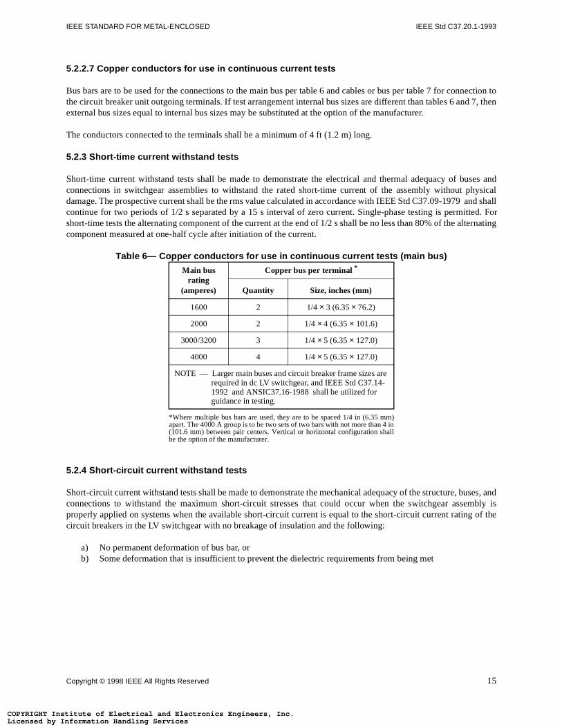
5.2.2.7 Copper conductors for use in continuous current tests
Bus bars are to be used for the connections to the main bus per table 6 and cables or bus per table 7 for conthe circuit breaker unit outgoing terminals. If test arrangement internal bus sizes are different than tables 6 anexternal bus sizes equal to internal bus sizes may be substituted at the option of the manufacturer.
The conductors connected to the terminals shall be a minimum of 4 ft (1.2 m) long.
5.2.3 Short-time current withstand tests
Short-time current withstand tests shall be made to demonstrate the electrical and thermal adequacy of bconnections in switchgear assemblies to withstand the rated short-time current of the assembly without pdamage. The prospective current shall be the rms value calculated in accordance with IEEE Std C37.09-1979 continue for two periods of 1/2 s separated by a 15 s interval of zero current. Single-phase testing is permishort-time tests the alternating component of the current at the end of 1/2 s shall be no less than 80% of the acomponent measured at one-half cycle after initiation of the current.
Table 6— Copper conductors for use in continuous current tests (main bus)
5.2.4 Short-circuit current withstand tests
Short-circuit current withstand tests shall be made to demonstrate the mechanical adequacy of the structure, bconnections to withstand the maximum short-circuit stresses that could occur when the switchgear asseproperly applied on systems when the available short-circuit current is equal to the short-circuit current ratingcircuit breakers in the LV switchgear with no breakage of insulation and the following:
a) No permanent deformation of bus bar, orb) Some deformation that is insufficient to prevent the dielectric requirements from being met
Main bus rating
(amperes)
Copper bus per terminal *
*Where multiple bus bars are used, they are to be spaced 1/4 in (6.35 mm)apart. The 4000 A group is to be two sets of two bars with not more than 4 in(101.6 mm) between pair centers. Vertical or horizontal configuration shallbe the option of the manufacturer.
Quantity Size, inches (mm)
1600 2 1/4 × 3 (6.35 × 76.2)
2000 2 1/4 × 4 (6.35 × 101.6)
3000/3200 3 1/4 × 5 (6.35 × 127.0)
4000 4 1/4 × 5 (6.35 × 127.0)
NOTE — Larger main buses and circuit breaker frame sizes are required in dc LV switchgear, and IEEE Std C37.14-1992 and ANSIC37.16-1988 shall be utilized for guidance in testing.
Copyright © 1998 IEEE All Rights Reserved 15
stitute of Electrical and Electronics Engineers, Inc.Information Handling Servicesstitute of Electrical and Electronics Engineers, Inc.Information Handling Services
IEEE Std C37.20.1-1993 LOW-VOLTAGE POWER CIRCUIT BREAKER SWITCHGEAR
on a 60e for the
applied.
ined bytion of
C37.09-
seriesr minus
% of the
less thanase rms
onductorhe neutralhe nearest
COPYRIGHT InLicensed by COPYRIGHT InLicensed by
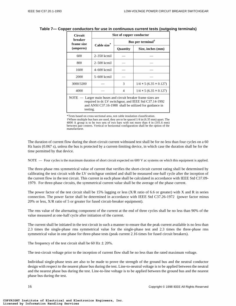
Table 7— Copper conductors for use in continuous current tests (outgoing terminals)
The duration of current flow during the short-circuit current withstand test shall be for no less than four cycles Hz basis (0.067 s), unless the bus is protected by a current-limiting device, in which case the duration shall btime permitted by that device.
NOTE — Four cycles is the maximum duration of short circuit expected on 600 V ac systems on which this equipment is
The three-phase rms symmetrical value of current that verifies the short-circuit current rating shall be determcalibrating the test circuit with the LV switchgear omitted and shall be measured one-half cycle after the incepthe current flow in the test circuit. This current in each phase shall be calculated in accordance with IEEE Std 1979. For three-phase circuits, the symmetrical current value shall be the average of the phase current.
The power factor of the test circuit shall be 15% lagging or less (X/R ratio of 6.6 or greater) with X and R inconnection. The power factor shall be determined in accordance with IEEE Std C37.26-1972 (power facto20% or less, X/R ratio of 5 or greater for fused circuit-breaker equipment).
The rms value of the alternating component of the current at the end of three cycles shall be no less than 90value measured at one-half cycle after initiation of the current.
The current shall be initiated in the test circuit in such a manner to ensure that the peak current available is no2.3 times the single-phase rms symmetrical value for the single-phase test and 2.3 times the three-phsymmetrical value in one phase for three-phase tests (peak current 2.16 times for fused circuit breakers).
The frequency of the test circuit shall be 60 Hz ± 20%.
The test-circuit voltage prior to the inception of current flow shall be no less than the rated maximum voltage.
Individual single-phase tests are also to be made to prove the strength of the ground bus and the neutral cdesign with respect to the nearest phase bus during the test. Line-to-neutral voltage is to be applied between tand the nearest phase bus during the test. Line-to-line voltage is to be applied between the ground bus and tphase bus during the test.
Circuit breaker
frame size (amperes)
Size of copper conductor
Cable size*
*Tests based on cross-sectional area, not cable insulation classification.
Bus per terminal†
†Where multiple bus bars are used, they are to be spaced 1/4 in (6.35 mm) apart. The4000 A group is to be two sets of two bars with not more than 4 in (101.6 mm)between pair centers. Vertical or horizontal configuration shall be the option of themanufacturer.
Quantity Size, inches (mm)
600 2–350 kcmil — —
800 2–500 kcmil — —
1600 4–600 kcmil — —
2000 5–600 kcmil — —
3000/3200 — 3 1/4 × 5 (6.35 × 0.127)
4000 — 4 1/4 × 5 (6.35 × 0.127)
NOTE — Larger main buses and circuit breaker frame sizes are required in dc LV switchgear, and IEEE Std C37.14-1992 and ANSI C37.16-1988 shall be utilized for guidance in testing.
16 Copyright © 1998 IEEE All Rights Reserved
stitute of Electrical and Electronics Engineers, Inc.Information Handling Servicesstitute of Electrical and Electronics Engineers, Inc.Information Handling Services
IEEE STANDARD FOR METAL-ENCLOSED IEEE Std C37.20.1-1993
ast 100te properded in
resistantn tested
, excepthaving ar greater
nclosure.
res with
rust on
testinishinge ferrousen days
ions forcimens,17-90.
COPYRIGHT InLicensed by COPYRIGHT InLicensed by
5.2.5 Mechanical endurance tests
LV switchgear with drawout circuit breakers shall have mechanical endurance test cycles consisting of at leoperations between connected and test positions for each frame size and type of circuit breaker to demonstrasequential operation and to establish satisfactory function of the following elements. All primary power, incluthe following, should be disconnected during these mechanical tests:
a) Separable primary contactsb) Separable control contactsc) Circuit breaker removable element position interlocks (every tenth operation to withdrawn position)d) Stored energy mechanism interlocks, as applicable (every tenth operation to withdrawn position)e) Structure mounted breaker position switchesf) Auxiliary switches mounted on stationary structure (every tenth operation)
5.2.6 Flame-resistance tests
Sheet-, molded-, or cast-insulating material used in a switchgear assembly shall not be classified as flame-unless they have a minimum average ignition time of 60 s and a maximum average burning time of 500 s whein accordance with method II of ASTM D229-91.
5.2.7 Rod entry test
5.2.7.1 Method for ventilated enclosures
This test shall prevent the insertion of a straight rod having a diameter of 0.500 in (12.7 mm) into the openingthat, if the distance between the openings and the nearest live part is greater than 4 in (101.6 mm), a rod diameter greater than 0.500 in (12.7 mm) shall be permitted to enter the opening, but a rod having a diametethan 0.750 in (19 mm) shall not be permitted to enter the opening.
5.2.7.2 Evaluation
The enclosure is considered to have met the requirements of this test if the appropriate rod cannot enter the e
5.2.8 Paint qualification test
The paint qualification test applies to all enclosures incorporating external ferrous parts. Nonferrous enclosuno external ferrous parts need not be tested.
The paint qualification test shall be performed to ensure the adequacy of finishes to inhibit the buildup of ferrous metal materials used for enclosures. The following methods are used.
5.2.8.1 Test specimens
Representative test panels of a 3 in × 6 in (76.2 mm × 152.4 mm) minimum size that can be accommodated by thechamber shall be provided. Each specimen shall be uniformly processed in the standard production paint-fsystem. At least four panels shall be selected for the test. All the test specimens shall be of standard gaugmetal equivalent to that used for the enclosure. The specimen shall be allowed to age for a minimum of sevbefore being tested.
5.2.8.2 Test apparatus
The test apparatus shall consist of a fog chamber, salt-solution reservoir, compressed-air supply, provisheating, and means of control. The conditions in the salt-spray chamber, including the positioning of the specontent of the salt solution, and temperature and pressure to be maintained, shall be as defined in ASTM-B1
Copyright © 1998 IEEE All Rights Reserved 17
stitute of Electrical and Electronics Engineers, Inc.Information Handling Servicesstitute of Electrical and Electronics Engineers, Inc.Information Handling Services
IEEE Std C37.20.1-1993 LOW-VOLTAGE POWER CIRCUIT BREAKER SWITCHGEAR
ort daily
D1654-
D1654-nce with
higher asf the test14-87.
rea to best the
er thearately or
er test
hall have
spray is
urfacee this rate the
irements test if
COPYRIGHT InLicensed by COPYRIGHT InLicensed by
5.2.8.3 Preparation of test specimens
Two of the test panels shall be suitably scribed for testing in accordance with ASTM D1654-79a.
5.2.8.4 Exposure of test specimens
All test specimens shall be tested in the salt-spray chamber for a period of 200 h continuously except for the shinterruptions necessary to inspect the test specimen or replenish the solution in the reservoir.
5.2.8.5 Procedure
After completion of the exposure period, the scribed specimens shall be processed in accordance with ASTM79a, either method A (tape) or method B (scraper).
5.2.8.6 Evaluation
The scribed specimens shall then be evaluated for creepage from the scribe mark in accordance with ASTM79a, rating schedule No. 1. The non-scribed specimen shall be evaluated for degree of blistering in accordaASTM D714-87.
5.2.8.7 Performance
The scribed specimens shall be judged to have met the requirements of the test if their rating number is 5 or determined by ASTM D1654-79a. The non-scribed specimens shall be judged to have met the requirements oif their blistering size is No. 6 or higher, and their frequency designation is F or M as determined by ASTM D7
5.2.9 Rain test for outdoor LV switchgear
The enclosure to be tested shall be equipped and complete with typical appurtenances, and placed in the asupplied with artificial precipitation. For multiple unit construction a minimum of two units shall be used to tejoints between units. A roof joint shall be included.
The artificial precipitation shall be supplied by a sufficient number of nozzles to produce a uniform spray oventire surface or surfaces under test. The various vertical surfaces of an enclosure may be tested sepcollectively, provided that a uniform spray is simultaneously applied to both a) and b) as follows:
a) The roof surface, from nozzles located at a suitable heightb) The floor outside the enclosure for a distance of approximately 3 ft (0.91 m) in front of the surface und
with the enclosure located at floor level.
The nozzles used for this test shall deliver a square-shaped spray pattern with uniform spray distribution and sa capacity of at least 7.1 gal/min (450 cm3/s) at a pressure of 60 lbf/in2 (41.4 N/cm2), and a spray angle ofapproximately 75 degrees. The centerline of the nozzles shall be inclined downward so that the top of the horizontal as it is directed toward the vertical and roof surfaces being tested.
The pressure at the nozzles shall be a minimum of 60 lbf/in2 (41.4 N/cm2) under flow conditions. (This isapproximately equivalent to rain driven by a 65 mi/h [29 m/s] wind.) The quantity of water applied to each sunder test shall be at least 0.2 in (0.5 cm) per unit surface per minute, and each surface so tested shall receivof artificial precipitation for a duration of 5 min. The spray nozzle shall not be more than 10 ft (3.05 m) fromnearest vertical surface under test.
After the test is completed, an inspection shall be made promptly to determine if the enclosure meets the requof outdoor construction. More specifically, the equipment shall have satisfactorily met the requirements of thisthe visible inspection indicates the following:
a) No water on primary or secondary insulation
18 Copyright © 1998 IEEE All Rights Reserved
stitute of Electrical and Electronics Engineers, Inc.Information Handling Servicesstitute of Electrical and Electronics Engineers, Inc.Information Handling Services
IEEE STANDARD FOR METAL-ENCLOSED IEEE Std C37.20.1-1993
imize
ding ofneed not
irements phase and
sts shall
otentialmers are
or 1800turer,
or relays,ested tont.
COPYRIGHT InLicensed by COPYRIGHT InLicensed by
b) No water on any electrical components or mechanisms of the assemblyc) No significant accumulation of water retained by the structure or other noninsulating parts (to min
corrosion)
5.3 Production tests
Production tests for LV switchgear shall be normal frequency dielectric tests, mechanical tests, grouninstrument transformer case tests, and electrical operation and control wiring tests. Drawout circuit breakers be tested in the assembly if they are tested separately.
5.3.1 Dielectric tests
Normal frequency withstand tests shall be made on each LV switchgear in accordance with the general requof 5.2.1 with the exception that tests across the open gap are not required. Tests shall be made between eachground with the other phases grounded.
Apply a test voltage of 1800 V between neutral and ground.
5.3.2 Mechanical operation tests
Mechanical tests shall be performed to ensure the proper functioning of mechanical interlocks, etc. These teensure the interchangeability of removable elements designed to be interchangeable.
5.3.3 Grounding of instrument transformer case test
The effectiveness of grounding of each instrument transformer case or frame shall be checked by a low psource such as 10 V or less using bells, buzzers, or lights. This test is required only when instrument transforof metal-case design.
5.3.4 Electrical operation and control-wiring tests
5.3.4.1 Control wiring continuity
The correctness of the control wiring of a switchgear assembly shall be verified by either or both
a) Actual electrical operation of the component control devicesb) Individual circuit continuity checks by electrical circuit testers
5.3.4.2 Control wiring insulation test
A 60 Hz test voltage shall be applied after all circuit grounds have been disconnected. Either 1500 V for 1 min V for 1 s may be utilized. All wires shall be tested either individually or in groups. At the option of the manufacswitchgear-mounted devices that have been individually tested may be disconnected during the test.
DC switchgear rated above 300 Vdc may require a test voltage higher than stated above.
5.3.4.3 Polarity verification
Tests or inspections shall be made to ensure that connections between instrument transformers and metersetc., are correctly connected with proper polarities in accordance with circuit diagrams. Instruments shall be tensure that pointers move in the proper direction. This does not require tests using primary voltage and curre
Copyright © 1998 IEEE All Rights Reserved 19
stitute of Electrical and Electronics Engineers, Inc.Information Handling Servicesstitute of Electrical and Electronics Engineers, Inc.Information Handling Services
IEEE Std C37.20.1-1993 LOW-VOLTAGE POWER CIRCUIT BREAKER SWITCHGEAR
equence
er, this
tchgear
ons. Tected toisture, or
the front
be 1, 2, 3,ear.se cases
front topment
polyphase of phaserting with 1.
COPYRIGHT InLicensed by COPYRIGHT InLicensed by
5.3.4.4 Sequence tests
LV switchgear involving the sequential operation of devices shall be tested to ensure that the devices in the sfunction properly and in the order intended.
This sequence test need not include remote equipment controlled by the switchgear assembly. Howevequipment may be simulated, where necessary.
5.4 Conformance tests
Conformance test procedures for LV switchgear are given in ANSI C37.51-1989.
5.5 Field dielectric tests
When normal frequency withstand tests are to be made on LV switchgear after installation in the field, the swishall not be tested at greater than 75% of the test values given in tables 1 and 2.
NOTE — Field tests are recommended when new units are added to an existing installation or after major field modificatiheequipment should be put in good condition prior to the field test. It is not expected that equipment shall be subjthese tests after it has been stored for long periods of time or has accumulated a large amount of dust, dirt, moother contaminants without first being restored to good condition.
6. Construction
6.1 General requirements
6.1.1 Buses and primary connections
Buses and primary connections shall be of copper or aluminum, or both. For bus ratings see 4.4.2.
6.1.1.1 Phase or polarity arrangements
Panel-mounted devices shall be mounted in the same arrangement as described in a) and b), as viewed fromof the panel.
a) The phase arrangement on three-phase assembled switchgear buses and primary connections shall(or A, B, C) from front to back, top to bottom, or left to right, as viewed from the front of the switchgCertain types of equipment may require other phasing arrangements and a neutral conductor. In thethe phasing shall be suitably indicated.
b) Polarities on dc assembled switchgear buses and connections shall be positive, neutral, negative,back, top to bottom, or left to right, as viewed from the front of the switchgear. Certain types of equimay require other polarity arrangements. In these cases the polarity shall be suitably indicated.
6.1.1.2 Phase sequence
The phase sequence on connection diagrams shall be such that when considering voltages to neutral on a system with respect to the element of time, the voltage of phase 1 will reach a maximum ahead of the voltage2, phase 3, etc. This sequence shall be designated as phase sequence in the consecutive numerical order sta
20 Copyright © 1998 IEEE All Rights Reserved
stitute of Electrical and Electronics Engineers, Inc.Information Handling Servicesstitute of Electrical and Electronics Engineers, Inc.Information Handling Services
IEEE STANDARD FOR METAL-ENCLOSED IEEE Std C37.20.1-1993
tions to NEMA
olts shall
ly in or
aint, shall
bus by
o remove
nism areIEEE Std
lays, and mounting
d (4110. Where
It ishigh
COPYRIGHT InLicensed by COPYRIGHT InLicensed by
6.1.1.3 Cable terminations
The LV switchgear shall provide space for the devices used for making electrical and mechanical connecincoming and outgoing cables. Each cable terminal connection point shall meet the bolt hole requirements ofCC 1-1984.
6.1.1.4 Bushings, potheads, or other terminators
These devices are not ordinarily used in LV switchgear.
6.1.1.5 Main bus splices
When bolts, nuts, and washers are provided for connecting through buses to other sections, the length of the bbe such that the dielectric integrity is not impaired.
6.1.2 Grounding
A ground bus shall be included which will electrically connect together the structures in a switchgear assembon which primary equipment or devices are mounted.
At all points of connection between the ground bus and the assembly, any nonconductive coatings, such as pbe removed or penetrated to ensure good electrical contact.
The ground bus for each group of vertical sections shall have facilities for connection to a station groundsuitable conductors.
Circuit connections to the ground bus shall be made so that it is not necessary to open-circuit the ground bus tany connection made to the ground bus.
Ground connections shall be provided for all removable elements to ensure that the frame and mechagrounded until the primary circuit is disconnected and the removable element is moved a safe distance. (See C37.100-1992 for the test or disconnected position definition.)
When mounted on metal switchgear structures, cases of instruments, instrument transformers, meters, resimilar devices shall be considered as being adequately grounded when secured to these structures by metalhardware with adequate provision for penetrating the paint film (see 5.3.3).
The ground bus shall be capable of carrying the rated short-time current of the LV switchgear for 0.5 s.
6.1.3 Control and secondary circuits and devices
6.1.3.1 Control, secondary, and logic level wiring
Flame-resistant, 600 V insulated copper wire, with a cross-sectional area not less than AWG No. 14 strandenominal cmil) shall be used on small wiring between component devices or parts of switchgear assemblieswire is connected across a hinge, flexible wire (37 or more strands) shall be used.
EXCEPTIONLV switchgear having single polarity direct-current circuits, rated above 250 V, shall be ungrounded. recommended that they be connected to ground only by protective or indicating devices of relatively resistance.
Copyright © 1998 IEEE All Rights Reserved 21
stitute of Electrical and Electronics Engineers, Inc.Information Handling Servicesstitute of Electrical and Electronics Engineers, Inc.Information Handling Services
IEEE Std C37.20.1-1993 LOW-VOLTAGE POWER CIRCUIT BREAKER SWITCHGEAR
maylass C or Smaller
rol, or
ds.
eet the
ped orwasherterminalcondary
assess
evicesh that all the wire
d wire.
ive voltage
sessed by
ated as
ositionposition
COPYRIGHT InLicensed by COPYRIGHT InLicensed by
For logic level wiring and for wiring from supervisory and annunciator devices to terminal blocks, smaller wirebe used provided it is adequately supported and meets the voltage and current requirements. Wire shall be CD stranded and shall meet the surge requirements of IEEE Std C37.90.1-1989 and IEEE Std C37.90.2-1987.wire, when used, shall not run in the same wire packs with other control and secondary wiring.
Bushings, grommets, or other mechanical protection shall be provided for the wiring where logic level, contsecondary wiring is run through a metal sheet, barrier, or raceway.
The internal wiring of component devices or parts shall be in accordance with the applicable industry standar
The insulated wire shall be Type TBS or SIS as listed in ANSI/NFPA 70-1993 or an equivalent and shall mrequirements of the following standards publication as applicable:
a) Type TBS NEMA WC5-1992/ICEA S-61-402b) Type SIS NEMA WC7-1991/ICEA S66-524
6.1.3.2 Secondary-wiring terminals
Stranded control wire shall have solderless terminals of the type wherein the body of the terminal is crimindented onto the conductor or where the wire is formed into an eye and confined within a crimp and flat assembly. Solderless terminals are not required for connection to devices that have integral pressure connectors. The wire may be soldered into terminals or, where desirable, directly to devices, such as sedisconnecting contacts, or to soldered terminals on supervisory control and annunciator equipment.
NOTE — In the absence with this standard of definitive performance requirements, compliance with this subclause can beedby referencing ANSI/UL 486A-1991.
6.1.3.3 Terminal blocks
Terminal blocks incorporating screw- or stud-and-nut-type terminals shall accommodate wire lugs or similar daffixed to stranded wire. Screw or stud and-nut-type terminals intended for use with stranded wire shall be sucstrands of the conductor are confined. Terminal blocks incorporating pressure connectors shall not damageand, when terminating stranded conductors, all strands shall be clamped within the connector.
Terminal blocks for external connections shall be suitable to accept AWG No. 10 (10380 nominal cmil) strandeThe use of solid wire is not recommended.
NOTES:
1 — Where long connections to the control battery are necessary the cable should be large enough to prevent excessdrop.
2 — In the absence with this standard of definitive performance requirements, compliance with this subclause can be asreferencing ANSI/UL 486A-1991.
6.1.3.4 Designation of auxiliary switches and contacts
The operation of auxiliary switches and contacts for circuit-interrupting and switching devices shall be designfollows:
a is open when the device is in the de-energized or nonoperated positionb is closed when the device is in the de-energized or nonoperated positionaa is open when the operating mechanism of the main device is in the de-energized or nonoperated pbb is closed when the operating mechanism of the main device is in the de-energized or nonoperated e, f, h, kare special contacts and auxiliary switches other than a, b, aa, or bb
22 Copyright © 1998 IEEE All Rights Reserved
stitute of Electrical and Electronics Engineers, Inc.Information Handling Servicesstitute of Electrical and Electronics Engineers, Inc.Information Handling Services
IEEE STANDARD FOR METAL-ENCLOSED IEEE Std C37.20.1-1993
ovableent
r open-n
merically
uits over
d to the
uits over
irectly toted fromevices are
voltageted from
COPYRIGHT InLicensed by COPYRIGHT InLicensed by
Auxiliary switches mounted on the stationary housing used to indicate the connected position of the remelement shall have the suffix TOC (circuit breaker truck-operated cell switch). The position of the removable elemin which the contacts are closed or open shall be designated. The following are examples:
Auxiliary switches mounted on the stationary housing operated by the circuit breaker to indicate circuit-breakeclosed position shall have a suffix MOC (circuit-breaker mechanism-operated cell switch). The open-closed positioof the circuit breaker shall be designated for the contacts. The following are examples:
If several auxiliary switches and contacts are present on the same device, they shall be designated nuconsecutive starting at 1, when necessary.
On diagrams of all types, contacts, and switches shall be shown in the de-energized position of the device.
6.1.3.5 Device function numbers
Device function numbers shall be in accordance with IEEE Std C37.2-1991.
6.1.3.6 Voltage limits of instrument and control circuits
Voltage and current transformers shall be used for all instruments, meters, and relays connected to ac circ240 V so as to reduce the voltage on instrument wiring, which must necessarily be closely grouped.
DC instruments, meters, and relays may be used directly on circuits up to 750 V if their cases are groundeswitchgear structures in accordance with 6.1.2.
DC instruments, meters, and relays together with their associated wiring and accessories, when used on circ750 V, shall be connected through isolating transducers.
EXCEPTIONS
1—Instruments, meters, and relays, along with their associated wiring and accessories may be connected dcircuits over 750 V dc when the instrument, meter, or relay and its associated wiring and accessories are isolaother instruments, meters, relays, and their associated wiring and accessories and where the cases of such dleft ungrounded and are provided with suitable protective barriers, insulated covers, or guards.
2—Ground detectors may be connected directly to circuits up to 600 V ac if connected to ground through dividing resistors. The resistors should not be mounted on the instrument panel and the wires should be isolaother control wiring.
52TOCa
------------------ is open when the circuit breaker is not in the connected position
52TOCb
------------------ is closed when the circuit breaker is not in the connected position
52MOCa
-------------------- is open when the circuit breaker is open
52MOCb
-------------------- is closed when the circuit breaker is open
Copyright © 1998 IEEE All Rights Reserved 23
stitute of Electrical and Electronics Engineers, Inc.Information Handling Servicesstitute of Electrical and Electronics Engineers, Inc.Information Handling Services
IEEE Std C37.20.1-1993 LOW-VOLTAGE POWER CIRCUIT BREAKER SWITCHGEAR
are nothen de-
s:
ontrol
sameion may
tection.
shall be
COPYRIGHT InLicensed by COPYRIGHT InLicensed by
6.1.3.7 Polarity of dc connections to device coils
Where coils on devices used in LV switchgear are connected to a dc supply and when de-energized,disconnected from both the positive and negative supply leads, such coils shall be so connected that, wenergized, they will be left connected to the negative supply lead to minimize the possibility of corrosion.
6.1.3.8 Voltage circuit protection
All voltage circuits used for control, relaying, or metering shall be protected within the LV switchgear as follow
a) All circuits supplied from external sources (ac or dc) shall have short-circuit protection within the csource incoming section. This may be provided by a single set of short-circuit protective devices.
b) All circuits supplied from internal sources (ac or dc) shall have short-circuit protection within the section as the supply source. If these circuits are supplied by a control power transformer, this protectbe in the primary circuit only.
Overcurrent protection of voltage circuits may be provided in addition to the required short-circuit protection.
Voltage transformers are required whenever the nominal primary voltage is greater than 240 V ac.
Other circuits supplying loads such as heaters, receptacles, or lights shall have overload and short-circuit pro
6.1.3.8.1 Control power transformers
Short-circuit protection of control power transformers shall be provided in accordance with table 8.
6.1.3.8.2 Voltage transformers
Voltage transformers shall be protected in the primary circuit with current-limiting fuses not larger than 10 A.
6.1.3.8.3 Isolation
Switches, fuse pullouts, and molded-case circuit breakers used to disconnect devices from the primary circuitsof a dead-front design.
24 Copyright © 1998 IEEE All Rights Reserved
stitute of Electrical and Electronics Engineers, Inc.Information Handling Servicesstitute of Electrical and Electronics Engineers, Inc.Information Handling Services
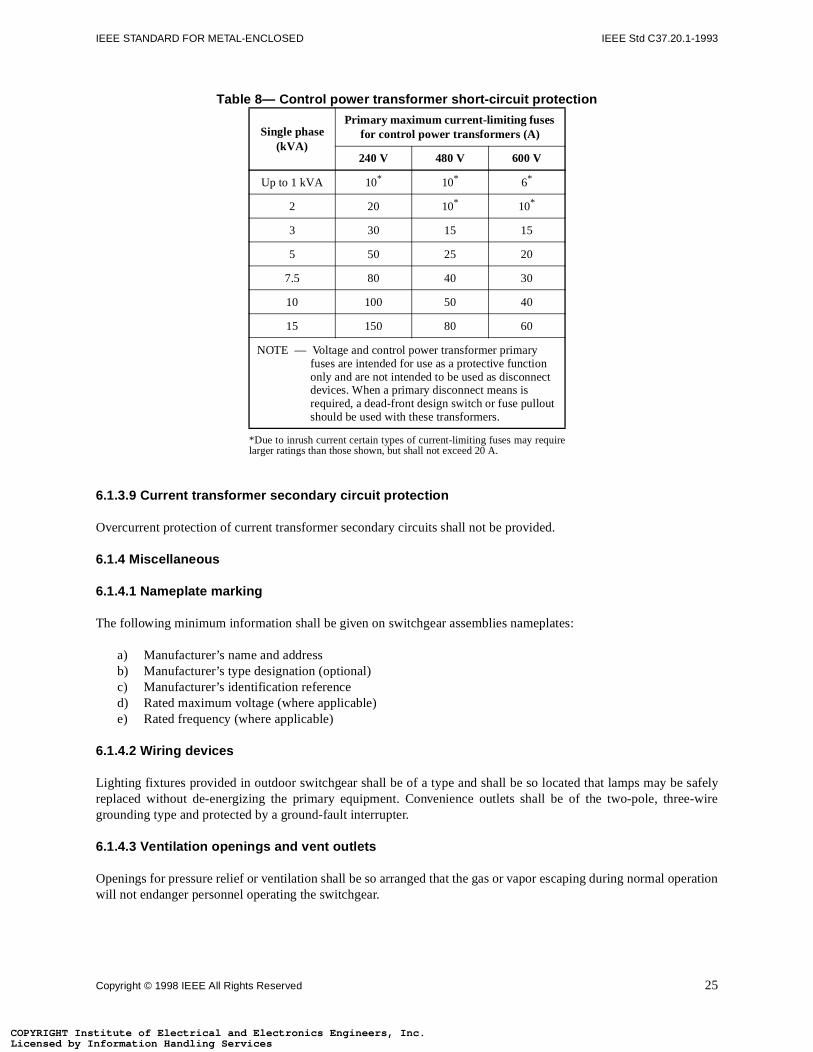
IEEE STANDARD FOR METAL-ENCLOSED IEEE Std C37.20.1-1993
e safelyee-wire
peration
COPYRIGHT InLicensed by COPYRIGHT InLicensed by
Table 8— Control power transformer short-circuit protection
6.1.3.9 Current transformer secondary circuit protection
Overcurrent protection of current transformer secondary circuits shall not be provided.
6.1.4 Miscellaneous
6.1.4.1 Nameplate marking
The following minimum information shall be given on switchgear assemblies nameplates:
a) Manufacturer’s name and addressb) Manufacturer’s type designation (optional)c) Manufacturer’s identification referenced) Rated maximum voltage (where applicable)e) Rated frequency (where applicable)
6.1.4.2 Wiring devices
Lighting fixtures provided in outdoor switchgear shall be of a type and shall be so located that lamps may breplaced without de-energizing the primary equipment. Convenience outlets shall be of the two-pole, thrgrounding type and protected by a ground-fault interrupter.
6.1.4.3 Ventilation openings and vent outlets
Openings for pressure relief or ventilation shall be so arranged that the gas or vapor escaping during normal owill not endanger personnel operating the switchgear.
Single phase (kVA)
Primary maximum current-limiting fuses for control power transformers (A)
240 V 480 V 600 V
Up to 1 kVA 10*
*Due to inrush current certain types of current-limiting fuses may requirelarger ratings than those shown, but shall not exceed 20 A.
10* 6*
2 20 10* 10*
3 30 15 15
5 50 25 20
7.5 80 40 30
10 100 50 40
15 150 80 60
NOTE — Voltage and control power transformer primary fuses are intended for use as a protective function only and are not intended to be used as disconnect devices. When a primary disconnect means is required, a dead-front design switch or fuse pullout should be used with these transformers.
Copyright © 1998 IEEE All Rights Reserved 25
stitute of Electrical and Electronics Engineers, Inc.Information Handling Servicesstitute of Electrical and Electronics Engineers, Inc.Information Handling Services
IEEE Std C37.20.1-1993 LOW-VOLTAGE POWER CIRCUIT BREAKER SWITCHGEAR
installed in
tments asarriers,
etals arem alloyand
essary, to
int.
t system
ng or an
ASTM
or use as
entilation breakerreakers)ach other.ses and
COPYRIGHT InLicensed by COPYRIGHT InLicensed by
6.1.4.4 Service disconnecting means
Switchgear assemblies designated as the service disconnecting means shall be designed so that they can beaccordance with the applicable provisions of Section 230 in ANSI/NFPA 70-1993.
6.2 Materials and finish
6.2.1 Materials
The materials for LV switchgear assemblies shall be sheet metal suitably supported. Barriers between comparlisted in 6.3 shall not be less than MSG No. 11 (nominal thickness 0.1196 in or 3 mm). All other covers, bpanels, and doors shall not be less than MSG No. 14 (nominal thickness 0.0747 in or 1.9 mm).
The minimum thickness of sheet metal used for LV switchgear is based on the use of steel. Where other mused the thickness shall be modified to provide equivalent strength and deflection. For example, if aluminusheet, having a yield strength of 20 000 lbf/in2, is used in the place of steel to provide equivalent strength deflection, it is required that the thickness specified above be increased by 50%.
Doors or panels used to support devices shall be increased in thickness or otherwise strengthened, as necsupport the devices.
6.2.2 Finishes and color
All steel surfaces to be painted shall receive a phosphatizing treatment or equivalent prior to application of pa
External and internal surfaces shall be coated with at least one coat of corrosion-resistant paint. The finish painshall comply with the requirement of 5.2.8.
The under-surfaces of outdoor assemblies shall additionally receive either a corrosion-resistant undercoatiadditional thickness of corrosion-resistant paint.
The preferred color for the finish on switchgear assemblies shall be light gray No. 61 in accordance with D1535-89, (MUNSELL NOTATION 8.3 G6.10/0.54).
NOTES:
1 — Internal detail parts may have metallic plating or equivalent in lieu of paint finish.
2 — For conformance testing a recognized organic coating system that has been investigated and found suitable fprotection against atmospheric corrosion of electrical equipment steel enclosures for outdoor use may be utilized.
6.3 Barriers
Each circuit breaker shall be mounted in a separate metal-enclosed compartment ventilated as necessary. Vopenings between compartments within the LV switchgear shall be such that the gases produced by circuitinterruption shall not impair the operation of adjacent compartments. When a bus sectionalizing breaker (or bis included, barriers shall be provided in the bus compartment to segregate the separate bus sections from eIf no bus sectionalizing breaker is involved, no barriers are provided in the bus compartments. Where buconnections penetrate internal barriers, suitable insulation or clearance shall be provided.
26 Copyright © 1998 IEEE All Rights Reserved
stitute of Electrical and Electronics Engineers, Inc.Information Handling Servicesstitute of Electrical and Electronics Engineers, Inc.Information Handling Services
IEEE STANDARD FOR METAL-ENCLOSED IEEE Std C37.20.1-1993
uses shall
ovablenectiont.
ot exceed
r, cover,
perated C37.13-
ree of
nt the
ipment
degree
COPYRIGHT InLicensed by COPYRIGHT InLicensed by
6.4 Buses and connections
The bus and connections shall be bare except where close clearances may make insulation necessary. The bbe mounted on Class 105 or higher insulation. See table 3.
6.5 Access doors and covers
A hinged door shall be furnished on the front of the structure to cover each circuit breaker compartment. Remtop and back plates shall also be provided in sufficient number to permit access to the bus and concompartments. For stationary equipment, a bolted cover may be used in the front of the breaker compartmen
For ease in handling, cover plates that are intended to provide access for inspecting and maintenance shall n12 ft2 (1.12 M2) in area or 60 lb (27 kg) unless they are equipped with lifting means or hinges.
To prevent access to energized fuses in power-circuit protectors, means shall be provided to interlock the dooor barrier so that it cannot be opened unless the circuit breaker or switch is in the open position.
6.6 Closing and tripping
Mechanical means for closing and tripping manually operated breakers and for manually tripping electrically obreakers shall be provided and shall be accessible without exposing the operator to live parts. See IEEE Std1990 for limitations on manually operated breakers.
6.7 Indoor LV switchgear
LV switchgear for indoor applications shall be ventilated enclosures intended primarily to provide a degprotection against contact with the enclosed equipment.
6.7.1 Requirements
When completely and properly installed, these enclosures
a) Shall provide a degree of protection against limited amounts of falling dirt; however, they will not preveentry of dust or liquids.
b) Shall prevent the insertion of the end portion of a straight rod of the specified diameter into the equcavity of the enclosure.
c) Shall not rust when subjected to the paint qualification test for 200 h.
6.7.2 Design tests
The enclosures shall be tested and evaluated by
a) The rod entry test in 5.2.7b) The paint qualification test in 5.2.8
6.8 Outdoor LV switchgear
LV switchgear for outdoor applications shall be housed in ventilated enclosures intended primarily to provide aof protection against falling rain, sleet, and external ice formations.
When completely and properly installed, these enclosures
Copyright © 1998 IEEE All Rights Reserved 27
stitute of Electrical and Electronics Engineers, Inc.Information Handling Servicesstitute of Electrical and Electronics Engineers, Inc.Information Handling Services
IEEE Std C37.20.1-1993 LOW-VOLTAGE POWER CIRCUIT BREAKER SWITCHGEAR
cept if
ipment
ted in the
tegories
in the
or are
e of theshall be
:m the
osing
ss of
contact
COPYRIGHT InLicensed by COPYRIGHT InLicensed by
a) Shall not permit water to enter the equipment cavity at a level higher than the lowest live part exconstructed to divert water from live parts, insulation, wiring, and shall have provisions for drainage.
b) Shall require the use of a tool to gain access to the equipment cavity or have provision for locking.c) Shall have doors that are equipped with latches and stops to hold the doors in the open position.d) Shall prevent the insertion of the end portion of a straight rod of the specified diameter into the equ
cavity of the enclosure.e) Shall not rust when subjected to the paint qualification test for 200 h.f) Shall have heaters or other effective means to minimize internal condensation.
For the design tests, the enclosures shall be tested and evaluated by
a) The rod entry test in 5.2.7b) The paint qualification test in 5.2.8c) The rain test in 5.2.9
NOTE — External icing tests are not required because LV switchgear has no external cavities to trap water when mounnormal position.
6.9 Pull box
A pull box for cables is not included in the standard equipment, but it may be furnished as an option.
6.10 Arrangements with stationary circuit breakers
Circuit breakers may be stationary mounted with or without disconnecting switches.
6.11 Arrangements with drawout circuit breakers
Drawout circuit breakers shall be equipped with self-coupling disconnecting devices and have the following cadiscussed in 6.11.1 through 6.11.6:
6.11.1 Interlocks
Mechanical interlocks shall be provided in LV switchgear as follows:
a) To prevent moving the circuit breaker to or from the connected position when the circuit breaker isclosed position
b) To prevent closing the circuit breaker unless the primary disconnecting devices are in full contactseparated by a safe distance
c) Circuit breakers equipped with stored energy mechanisms shall be designed to prevent the releasstored energy unless the mechanism has been fully charged. Operators and service personnel protected from the effects of accidental discharge of the stored energy by any of the following means1) Interlocks provided in the housing to prevent the complete withdrawal of the circuit breaker fro
housing when stored energy mechanism is charged2) A suitable device provided to prevent the complete withdrawal of the circuit breaker until the cl
function is blocked3) A mechanism is provided to automatically discharge the stored energy during the proce
withdrawing the circuit breaker from the housing4) Mechanisms as described above are not required provided the stored energy mechanism and
assembly are isolated within the breaker element and service is not possible
28 Copyright © 1998 IEEE All Rights Reserved
stitute of Electrical and Electronics Engineers, Inc.Information Handling Servicesstitute of Electrical and Electronics Engineers, Inc.Information Handling Services
IEEE STANDARD FOR METAL-ENCLOSED IEEE Std C37.20.1-1993
lement shall be
hem or
emovable
le in thercuits.
to these
e door or
provided
tomatic
n of therevented
ts on the
hen the
ll not bed in such
COPYRIGHT InLicensed by COPYRIGHT InLicensed by
6.11.2 Circuit breaker retention and locking
Means shall be provided for positively holding the circuit breaker in place in the housing when the removable eis in the connected or test position. When breakers are left in the housing in the disconnected position, theysecurely held in that position by suitable mechanical means.
Additionally, means shall be provided for locking the circuit breakers in the disconnected position to prevent treplacement breakers from being moved into the connected position.
6.11.3 Fuse accessibility
Where the removable element consists of a fused circuit breaker, the fuses shall be accessible only when the relement is withdrawn to the test, disconnected, or into the withdrawn position.
6.11.4 Removable element interchangeability
All removable elements of the same type and rating on a given assembly shall be physically interchangeabcorresponding stationary housings. This need not include electrical interchangeability of secondary control ci
6.11.5 Fuses on separate removable elements
Current-limiting fuses may be mounted on separate removable elements. The requirements of 6.11.4 applyelements, and in addition, these elements must be only used in series with circuit breakers or switches.
To prevent access to energized fuses on these removable elements, means shall be provided to interlock thcover so that it cannot be opened unless the associated circuit breaker or switch is in the open position.
If the fuses are located on the line side of the associated circuit breaker, interlocking of the breaker shall be to prevent connection or disconnection under load.
6.11.6 Secondary disconnect devices
Control wiring connections between stationary structure and the removable element shall be provided with au(self-coupling) contacts or manual plug and receptacle for disconnection.
The manual control connector shall be either interlocked or inaccessible to prevent connection or disconnectiocontrol circuits when the removable element is in the connected position and the removable element shall be pfrom being installed in the connected position unless the manual control connector is connected.
With the manual arrangement, all connections shall be group connectable simultaneously with the male contacremovable element and the female receptacles on the stationary structure.
NOTE — The intent of this requirement is to ensure that the control connection is always made to the circuit breaker wcircuit breaker is in the connected position.
6.12 Primary cable space
The clear cabling space independent of all projections, obstructions, or interference from moving parts, shaless in total area than 250% of the total cross-sectional area of the maximum number of cables that may be usespace.
Table 9 gives the minimum area for the more common multiple-cable connections.
Copyright © 1998 IEEE All Rights Reserved 29
stitute of Electrical and Electronics Engineers, Inc.Information Handling Servicesstitute of Electrical and Electronics Engineers, Inc.Information Handling Services
IEEE Std C37.20.1-1993 LOW-VOLTAGE POWER CIRCUIT BREAKER SWITCHGEAR
otential991 for
idualitchgear
itchgeard, the
arts ande derated
ess thanis is notation on
COPYRIGHT InLicensed by COPYRIGHT InLicensed by
6.13 Precautionary labels
Each LV switchgear should be provided with appropriate precautionary labels to call the user’s attention to phazards that are inherent to the equipment and which cannot be eliminated by design. See ANSI Z535.4-1recommendations.
6.14 Lifting devices
Lifting devices may be provided to facilitate the insertion or removal of drawout circuit breakers from their indivcompartments and consist generally of a wheeled hoist device or an overhead lift device attached to the switself.
7. Application guide for LV switchgear
7.1 Unusual service conditions
It is strongly recommended that the usual service conditions, as described in clause 3., be provided for LV swapplications, if practical (artificially, if necessary). However, if unusual conditions exist and cannot be eliminatefollowing considerations apply:
7.1.1 Ambient air temperature above 40 °°°°C
When LV switchgear is applied where the ambient air temperature is higher than 40 °C, its performance may beaffected, and special consideration should be given to these applications. The total temperature limits for pmaterials as given in 4.5 should not be exceeded. Therefore, for the higher ambients, the equipment should bto a continuous current value that maintains the total temperature limits.
7.1.2 Ambient air temperature below −−−−30 °°°°C
Special consideration is also required when LV switchgear is applied where the ambient air temperature is l−30 °C. Space heating and thermal insulation to minimize the effects of exposure should be considered. If thpossible, the effect of low temperatures on the functional performance of such materials as oils, plastic insulprimary and secondary circuits, control wire insulation, and lubricants should be considered.
30 Copyright © 1998 IEEE All Rights Reserved
stitute of Electrical and Electronics Engineers, Inc.Information Handling Servicesstitute of Electrical and Electronics Engineers, Inc.Information Handling Services
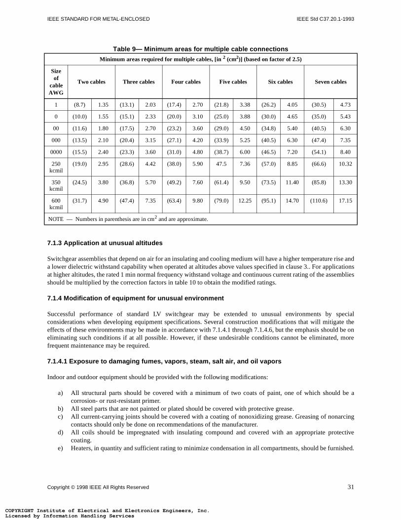
IEEE STANDARD FOR METAL-ENCLOSED IEEE Std C37.20.1-1993
rise andlicationssemblies
specialate theuld be on, more
be a
arcing
ective
ished.
3
3
0
5
0
2
0
15
COPYRIGHT InLicensed by COPYRIGHT InLicensed by
Table 9— Minimum areas for multiple cable connections
7.1.3 Application at unusual altitudes
Switchgear assemblies that depend on air for an insulating and cooling medium will have a higher temperaturea lower dielectric withstand capability when operated at altitudes above values specified in clause 3.. For appat higher altitudes, the rated 1 min normal frequency withstand voltage and continuous current rating of the asshould be multiplied by the correction factors in table 10 to obtain the modified ratings.
7.1.4 Modification of equipment for unusual environment
Successful performance of standard LV switchgear may be extended to unusual environments by considerations when developing equipment specifications. Several construction modifications that will mitigeffects of these environments may be made in accordance with 7.1.4.1 through 7.1.4.6, but the emphasis shoeliminating such conditions if at all possible. However, if these undesirable conditions cannot be eliminatedfrequent maintenance may be required.
7.1.4.1 Exposure to damaging fumes, vapors, steam, salt air, and oil vapors
Indoor and outdoor equipment should be provided with the following modifications:
a) All structural parts should be covered with a minimum of two coats of paint, one of which shouldcorrosion- or rust-resistant primer.
b) All steel parts that are not painted or plated should be covered with protective grease.c) All current-carrying joints should be covered with a coating of nonoxidizing grease. Greasing of non
contacts should only be done on recommendations of the manufacturer.d) All coils should be impregnated with insulating compound and covered with an appropriate prot
coating.e) Heaters, in quantity and sufficient rating to minimize condensation in all compartments, should be furn
Minimum areas required for multiple cables, [in 2 (cm2)] (based on factor of 2.5)
Size of
cable AWG
Two cables Three cables Four cables Five cables Six cables Seven cables
1 (8.7) 1.35 (13.1) 2.03 (17.4) 2.70 (21.8) 3.38 (26.2) 4.05 (30.5) 4.7
0 (10.0) 1.55 (15.1) 2.33 (20.0) 3.10 (25.0) 3.88 (30.0) 4.65 (35.0) 5.4
00 (11.6) 1.80 (17.5) 2.70 (23.2) 3.60 (29.0) 4.50 (34.8) 5.40 (40.5) 6.3
000 (13.5) 2.10 (20.4) 3.15 (27.1) 4.20 (33.9) 5.25 (40.5) 6.30 (47.4) 7.3
0000 (15.5) 2.40 (23.3) 3.60 (31.0) 4.80 (38.7) 6.00 (46.5) 7.20 (54.1) 8.4
250 kcmil
(19.0) 2.95 (28.6) 4.42 (38.0) 5.90 47.5 7.36 (57.0) 8.85 (66.6) 10.3
350 kcmil
(24.5) 3.80 (36.8) 5.70 (49.2) 7.60 (61.4) 9.50 (73.5) 11.40 (85.8) 13.3
600 kcmil
(31.7) 4.90 (47.4) 7.35 (63.4) 9.80 (79.0) 12.25 (95.1) 14.70 (110.6) 17.
NOTE — Numbers in parenthesis are in cm2 and are approximate.
Copyright © 1998 IEEE All Rights Reserved 31
stitute of Electrical and Electronics Engineers, Inc.Information Handling Servicesstitute of Electrical and Electronics Engineers, Inc.Information Handling Services
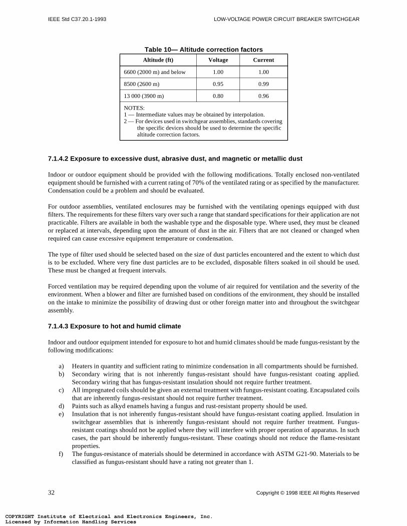
IEEE Std C37.20.1-1993 LOW-VOLTAGE POWER CIRCUIT BREAKER SWITCHGEAR
tilatedfacturer.
ith dust are not
e cleaneded when
hich dustbe used.
y of thenstalledchgear
nt by the
ished.pplied.
ed coils
tion inungus-In such-resistant
ls to be
COPYRIGHT InLicensed by COPYRIGHT InLicensed by
Table 10— Altitude correction factors
7.1.4.2 Exposure to excessive dust, abrasive dust, and magnetic or metallic dust
Indoor or outdoor equipment should be provided with the following modifications. Totally enclosed non-venequipment should be furnished with a current rating of 70% of the ventilated rating or as specified by the manuCondensation could be a problem and should be evaluated.
For outdoor assemblies, ventilated enclosures may be furnished with the ventilating openings equipped wfilters. The requirements for these filters vary over such a range that standard specifications for their applicationpracticable. Filters are available in both the washable type and the disposable type. Where used, they must bor replaced at intervals, depending upon the amount of dust in the air. Filters that are not cleaned or changrequired can cause excessive equipment temperature or condensation.
The type of filter used should be selected based on the size of dust particles encountered and the extent to wis to be excluded. Where very fine dust particles are to be excluded, disposable filters soaked in oil should These must be changed at frequent intervals.
Forced ventilation may be required depending upon the volume of air required for ventilation and the severitenvironment. When a blower and filter are furnished based on conditions of the environment, they should be ion the intake to minimize the possibility of drawing dust or other foreign matter into and throughout the switassembly.
7.1.4.3 Exposure to hot and humid climate
Indoor and outdoor equipment intended for exposure to hot and humid climates should be made fungus-resistafollowing modifications:
a) Heaters in quantity and sufficient rating to minimize condensation in all compartments should be furnb) Secondary wiring that is not inherently fungus-resistant should have fungus-resistant coating a
Secondary wiring that has fungus-resistant insulation should not require further treatment.c) All impregnated coils should be given an external treatment with fungus-resistant coating. Encapsulat
that are inherently fungus-resistant should not require further treatment.d) Paints such as alkyd enamels having a fungus and rust-resistant property should be used.e) Insulation that is not inherently fungus-resistant should have fungus-resistant coating applied. Insula
switchgear assemblies that is inherently fungus-resistant should not require further treatment. Fresistant coatings should not be applied where they will interfere with proper operation of apparatus. cases, the part should be inherently fungus-resistant. These coatings should not reduce the flameproperties.
f) The fungus-resistance of materials should be determined in accordance with ASTM G21-90. Materiaclassified as fungus-resistant should have a rating not greater than 1.
Altitude (ft) Voltage Current
6600 (2000 m) and below 1.00 1.00
8500 (2600 m) 0.95 0.99
13 000 (3900 m) 0.80 0.96
NOTES:1 — Intermediate values may be obtained by interpolation.2 — For devices used in switchgear assemblies, standards covering
the specific devices should be used to determine the specific altitude correction factors.
32 Copyright © 1998 IEEE All Rights Reserved
stitute of Electrical and Electronics Engineers, Inc.Information Handling Servicesstitute of Electrical and Electronics Engineers, Inc.Information Handling Services
IEEE STANDARD FOR METAL-ENCLOSED IEEE Std C37.20.1-1993
periodic
ng.
specific
of thes of anled. Theng value they arer for thervening
of the LV
ecified.ecificallymay beence, theined.
a nuclear
on other
oes not of LV
COPYRIGHT InLicensed by COPYRIGHT InLicensed by
g) Materials that are made fungus-resistant by means of a coating should have the coating reapplied atintervals.
7.1.4.4 Exposure to explosive mixtures of dust or gases
Application of LV switchgear for explosion-proof requirements is not recommended.
7.1.4.5 Exposure to abnormal vibration, shocks, or tilting
Indoor and outdoor equipment is designed for mounting on level structures free from vibration, shocks, or tilti
Since these conditions vary so widely, it is recommended that the manufacturer be consulted for each application where vibration, shocks, or tilting are to be encountered.
It is important that the full nature of the abnormal motion be specified. The magnitude and frequency rangedynamic motion is required so that resonances may be investigated. This is usually specified by meanacceleration response spectrum curve for the mounting surface on which the LV switchgear is to be instalresponse spectrum is a plot of the maximum response of single-degree-of-freedom bodies, at a dampiexpressed as a percent of critical damping of different natural frequencies. These bodies are plotted whenrigidly mounted on the surface of interest (i.e., on the ground for the ground response spectrum or on the floofloor response spectrum) when that surface is subjected to a given abnormal motion as modified by any intestructures. The response spectrum is useful in designing a test or in making an analysis of the performance switchgear equipment mounted on the same surface and subjected to the same motion.
In the case of tilting, it is also important that the maximum angles of tilt, both transverse and longitudinal, be spThe exact performance requirements should also be defined. It should be recognized that equipment spdesigned for a usual installation on a substantially level surface free from excessive vibration, shock, or tilting damaged and may not be able to function properly when subjected to excessive motion and displacement. Happlication should be carefully analyzed and the essential performance requirements should be precisely def
7.1.4.6 Exposure to seismic shock
Because of the importance of adequate performance of equipment when applied as Class 1E equipment in power generating station, IEEE Std 344-1987 was developed for this application.
7.2 System characteristics—Voltage and frequency
LV switchgear is designed for use on three-phase, 60 Hz, grounded or ungrounded ac systems. Applicationtypes of systems such as the following should be reviewed with the manufacturer:
a) DCb) Three phase, four-wire with insulated neutralc) Two phased) Frequency other than 60 Hz or other than sinusoidal waveform
LV switchgear is intended for application on systems where the maximum operating voltage of the system dexceed the rated maximum voltage for which the equipment is designed. The voltages for various typesswitchgear are listed in tables 1 and 2.
7.3 Overvoltage considerations—Insulation levels
The insulation levels to which LV switchgear is designed are also listed in tables 1 and 2.
Copyright © 1998 IEEE All Rights Reserved 33
stitute of Electrical and Electronics Engineers, Inc.Information Handling Servicesstitute of Electrical and Electronics Engineers, Inc.Information Handling Services
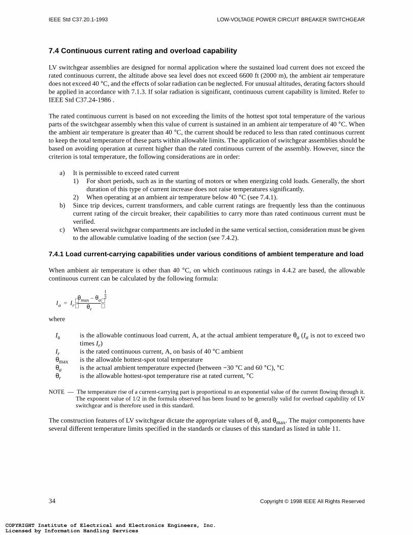
IEEE Std C37.20.1-1993 LOW-VOLTAGE POWER CIRCUIT BREAKER SWITCHGEAR
ceed theperature
shouldefer to
various
rrentould be
since the
e short
tinuousust be
be given
ble
oughy of LV
COPYRIGHT InLicensed by COPYRIGHT InLicensed by
7.4 Continuous current rating and overload capability
LV switchgear assemblies are designed for normal application where the sustained load current does not exrated continuous current, the altitude above sea level does not exceed 6600 ft (2000 m), the ambient air temdoes not exceed 40 °C, and the effects of solar radiation can be neglected. For unusual altitudes, derating factorsbe applied in accordance with 7.1.3. If solar radiation is significant, continuous current capability is limited. RIEEE Std C37.24-1986 .
The rated continuous current is based on not exceeding the limits of the hottest spot total temperature of theparts of the switchgear assembly when this value of current is sustained in an ambient air temperature of 40 °C. Whenthe ambient air temperature is greater than 40 °C, the current should be reduced to less than rated continuous cuto keep the total temperature of these parts within allowable limits. The application of switchgear assemblies shbased on avoiding operation at current higher than the rated continuous current of the assembly. However, criterion is total temperature, the following considerations are in order:
a) It is permissible to exceed rated current1) For short periods, such as in the starting of motors or when energizing cold loads. Generally, th
duration of this type of current increase does not raise temperatures significantly.2) When operating at an ambient air temperature below 40 °C (see 7.4.1).
b) Since trip devices, current transformers, and cable current ratings are frequently less than the concurrent rating of the circuit breaker, their capabilities to carry more than rated continuous current mverified.
c) When several switchgear compartments are included in the same vertical section, consideration must to the allowable cumulative loading of the section (see 7.4.2).
7.4.1 Load current-carrying capabilities under various conditions of ambient temperature and load
When ambient air temperature is other than 40 °C, on which continuous ratings in 4.4.2 are based, the allowacontinuous current can be calculated by the following formula:
where
Ia is the allowable continuous load current, A, at the actual ambient temperature θa (Ia is not to exceed twotimes Ir)
Ir is the rated continuous current, A, on basis of 40 °C ambientθmax is the allowable hottest-spot total temperatureθa is the actual ambient temperature expected (between −30 °C and 60 °C), °Cθr is the allowable hottest-spot temperature rise at rated current, °C
NOTE — The temperature rise of a current-carrying part is proportional to an exponential value of the current flowing thr it.The exponent value of 1/2 in the formula observed has been found to be generally valid for overload capabilitswitchgear and is therefore used in this standard.
The construction features of LV switchgear dictate the appropriate values of θr and θmax. The major components haveseveral different temperature limits specified in the standards or clauses of this standard as listed in table 11.
Ia I r
θmax θa–
θr-----------------------
12---
=
34 Copyright © 1998 IEEE All Rights Reserved
stitute of Electrical and Electronics Engineers, Inc.Information Handling Servicesstitute of Electrical and Electronics Engineers, Inc.Information Handling Services
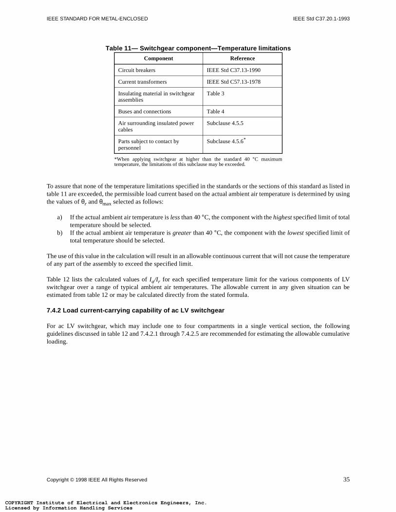
IEEE STANDARD FOR METAL-ENCLOSED IEEE Std C37.20.1-1993
s listed ind by using
erature
LV can be
owingmulative
COPYRIGHT InLicensed by COPYRIGHT InLicensed by
Table 11— Switchgear component—Temperature limitations
To assure that none of the temperature limitations specified in the standards or the sections of this standard atable 11 are exceeded, the permissible load current based on the actual ambient air temperature is determinethe values of θr and θmax selected as follows:
a) If the actual ambient air temperature is less than 40 °C, the component with the highest specified limit of totaltemperature should be selected.
b) If the actual ambient air temperature is greater than 40 °C, the component with the lowest specified limit oftotal temperature should be selected.
The use of this value in the calculation will result in an allowable continuous current that will not cause the tempof any part of the assembly to exceed the specified limit.
Table 12 lists the calculated values of Ia/Ir for each specified temperature limit for the various components of switchgear over a range of typical ambient air temperatures. The allowable current in any given situationestimated from table 12 or may be calculated directly from the stated formula.
7.4.2 Load current-carrying capability of ac LV switchgear
For ac LV switchgear, which may include one to four compartments in a single vertical section, the follguidelines discussed in table 12 and 7.4.2.1 through 7.4.2.5 are recommended for estimating the allowable culoading.
Component Reference
Circuit breakers IEEE Std C37.13-1990
Current transformers IEEE Std C57.13-1978
Insulating material in switchgear assemblies
Table 3
Buses and connections Table 4
Air surrounding insulated power cables
Subclause 4.5.5
Parts subject to contact by personnel
Subclause 4.5.6*
*When applying switchgear at higher than the standard 40 °C maximumtemperature, the limitations of this subclause may be exceeded.
Copyright © 1998 IEEE All Rights Reserved 35
stitute of Electrical and Electronics Engineers, Inc.Information Handling Servicesstitute of Electrical and Electronics Engineers, Inc.Information Handling Services
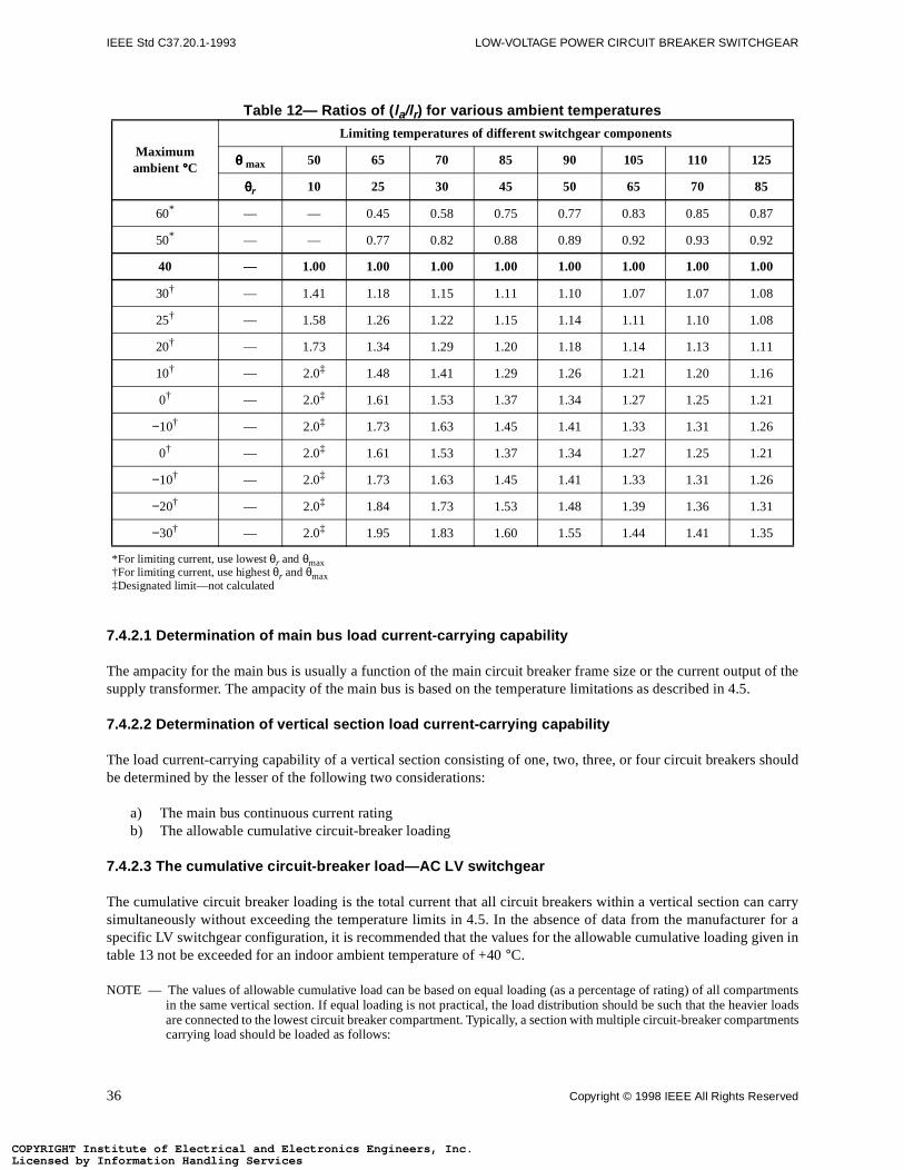
IEEE Std C37.20.1-1993 LOW-VOLTAGE POWER CIRCUIT BREAKER SWITCHGEAR
t of the.
should
carryer for aiven in
artmentser loadsrtments
COPYRIGHT InLicensed by COPYRIGHT InLicensed by
Table 12— Ratios of ( la/lr) for various ambient temperatures
7.4.2.1 Determination of main bus load current-carrying capability
The ampacity for the main bus is usually a function of the main circuit breaker frame size or the current outpusupply transformer. The ampacity of the main bus is based on the temperature limitations as described in 4.5
7.4.2.2 Determination of vertical section load current-carrying capability
The load current-carrying capability of a vertical section consisting of one, two, three, or four circuit breakers be determined by the lesser of the following two considerations:
a) The main bus continuous current ratingb) The allowable cumulative circuit-breaker loading
7.4.2.3 The cumulative circuit-breaker load—AC LV switchgear
The cumulative circuit breaker loading is the total current that all circuit breakers within a vertical section cansimultaneously without exceeding the temperature limits in 4.5. In the absence of data from the manufacturspecific LV switchgear configuration, it is recommended that the values for the allowable cumulative loading gtable 13 not be exceeded for an indoor ambient temperature of +40 °C.
NOTE — The values of allowable cumulative load can be based on equal loading (as a percentage of rating) of all compin the same vertical section. If equal loading is not practical, the load distribution should be such that the heaviare connected to the lowest circuit breaker compartment. Typically, a section with multiple circuit-breaker compacarrying load should be loaded as follows:
Maximum ambient °°°°C
Limiting temperatures of different switchgear components
θθθθ max 50 65 70 85 90 105 110 125
θθθθr 10 25 30 45 50 65 70 85
60*
*For limiting current, use lowest θr and θmax
— — 0.45 0.58 0.75 0.77 0.83 0.85 0.87
50* — — 0.77 0.82 0.88 0.89 0.92 0.93 0.92
40 — 1.00 1.00 1.00 1.00 1.00 1.00 1.00 1.00
30†
†For limiting current, use highest θr and θmax
— 1.41 1.18 1.15 1.11 1.10 1.07 1.07 1.08
25† — 1.58 1.26 1.22 1.15 1.14 1.11 1.10 1.08
20† — 1.73 1.34 1.29 1.20 1.18 1.14 1.13 1.11
10† — 2.0‡
‡Designated limit—not calculated
1.48 1.41 1.29 1.26 1.21 1.20 1.16
0† — 2.0‡ 1.61 1.53 1.37 1.34 1.27 1.25 1.21
−10† — 2.0‡ 1.73 1.63 1.45 1.41 1.33 1.31 1.26
0† — 2.0‡ 1.61 1.53 1.37 1.34 1.27 1.25 1.21
−10† — 2.0‡ 1.73 1.63 1.45 1.41 1.33 1.31 1.26
−20† — 2.0‡ 1.84 1.73 1.53 1.48 1.39 1.36 1.31
−30† — 2.0‡ 1.95 1.83 1.60 1.55 1.44 1.41 1.35
36 Copyright © 1998 IEEE All Rights Reserved
stitute of Electrical and Electronics Engineers, Inc.Information Handling Servicesstitute of Electrical and Electronics Engineers, Inc.Information Handling Services
IEEE STANDARD FOR METAL-ENCLOSED IEEE Std C37.20.1-1993
nsulted.
circuitand the
COPYRIGHT InLicensed by COPYRIGHT InLicensed by
a) Four circuit breaker compartments
b) Three circuit breaker compartments
c) Two circuit breaker compartments
If other arrangements are required, such as forced ventilation, it is recommended that the manufacturer be co
When different ratings of circuit breakers are utilized in the same vertical section, the allowable cumulativebreaker loading should be determined based on the number of circuit breakers in the vertical section corresponding value for each circuit breaker.
Bottom compartment 90% of compartment rating
Next to bottom compartment 75% of compartment rating
Next to top compartment 60% of compartment rating
Top compartment 50% of compartment rating
Bottom compartment 90% of compartment rating
Middle compartment 75% of compartment rating
Top compartment 60% of compartment rating
Bottom compartment 90% of compartment rating
Top compartment 75% of compartment rating
Copyright © 1998 IEEE All Rights Reserved 37
stitute of Electrical and Electronics Engineers, Inc.Information Handling Servicesstitute of Electrical and Electronics Engineers, Inc.Information Handling Services
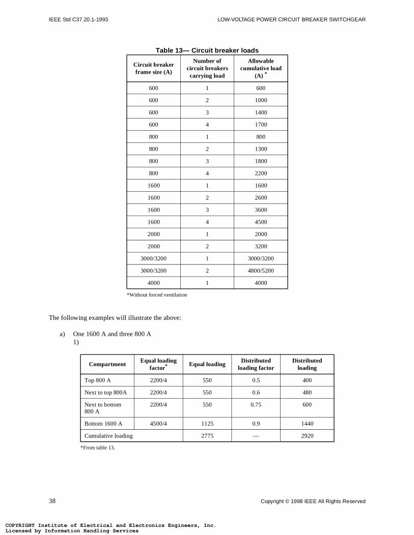
IEEE Std C37.20.1-1993 LOW-VOLTAGE POWER CIRCUIT BREAKER SWITCHGEAR
COPYRIGHT InLicensed by COPYRIGHT InLicensed by
Table 13— Circuit breaker loads
The following examples will illustrate the above:
a) One 1600 A and three 800 A1)
Circuit breaker frame size (A)
Number of circuit breakers carrying load
Allowable cumulative load
(A) *
*Without forced ventilation
600 1 600
600 2 1000
600 3 1400
600 4 1700
800 1 800
800 2 1300
800 3 1800
800 4 2200
1600 1 1600
1600 2 2600
1600 3 3600
1600 4 4500
2000 1 2000
2000 2 3200
3000/3200 1 3000/3200
3000/3200 2 4800/5200
4000 1 4000
CompartmentEqual loading
factor*
*From table 13.
Equal loadingDistributed
loading factorDistributed
loading
Top 800 A 2200/4 550 0.5 400
Next to top 800A 2200/4 550 0.6 480
Next to bottom 800 A
2200/4 550 0.75 600
Bottom 1600 A 4500/4 1125 0.9 1440
Cumulative loading 2775 — 2920
38 Copyright © 1998 IEEE All Rights Reserved
stitute of Electrical and Electronics Engineers, Inc.Information Handling Servicesstitute of Electrical and Electronics Engineers, Inc.Information Handling Services
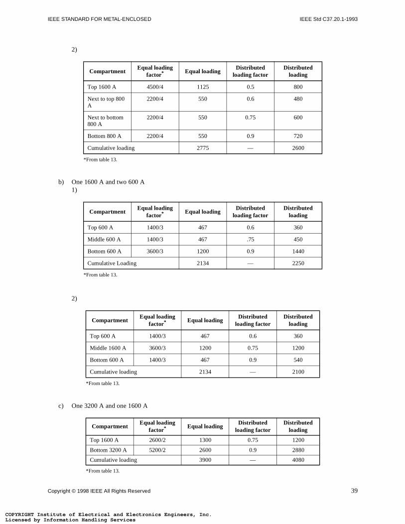
IEEE STANDARD FOR METAL-ENCLOSED IEEE Std C37.20.1-1993
COPYRIGHT InLicensed by COPYRIGHT InLicensed by
2)
b) One 1600 A and two 600 A1)
2)
c) One 3200 A and one 1600 A
CompartmentEqual loading
factor*
*From table 13.
Equal loadingDistributed
loading factorDistributed
loading
Top 1600 A 4500/4 1125 0.5 800
Next to top 800 A
2200/4 550 0.6 480
Next to bottom 800 A
2200/4 550 0.75 600
Bottom 800 A 2200/4 550 0.9 720
Cumulative loading 2775 — 2600
CompartmentEqual loading
factor*
*From table 13.
Equal loadingDistributed
loading factorDistributed
loading
Top 600 A 1400/3 467 0.6 360
Middle 600 A 1400/3 467 .75 450
Bottom 600 A 3600/3 1200 0.9 1440
Cumulative Loading 2134 — 2250
CompartmentEqual loading
factor*
*From table 13.
Equal loadingDistributed
loading factorDistributed
loading
Top 600 A 1400/3 467 0.6 360
Middle 1600 A 3600/3 1200 0.75 1200
Bottom 600 A 1400/3 467 0.9 540
Cumulative loading 2134 — 2100
CompartmentEqual loading
factor*
*From table 13.
Equal loadingDistributed
loading factorDistributed
loading
Top 1600 A 2600/2 1300 0.75 1200
Bottom 3200 A 5200/2 2600 0.9 2880
Cumulative loading 3900 — 4080
Copyright © 1998 IEEE All Rights Reserved 39
stitute of Electrical and Electronics Engineers, Inc.Information Handling Servicesstitute of Electrical and Electronics Engineers, Inc.Information Handling Services
IEEE Std C37.20.1-1993 LOW-VOLTAGE POWER CIRCUIT BREAKER SWITCHGEAR
y
nductors
tem oncircuit
autions
vicesircuit
circuit
oltageles, and
eet the
7 are thelicationers with
consultedents.
COPYRIGHT InLicensed by COPYRIGHT InLicensed by
7.4.2.4 Conductor temperature
Cables connected to LV switchgear should be capable of withstanding the 65 °C ambient temperature to which themay be subjected.
7.4.2.5 Conductor terminations
Consideration should be given to the use of suitable connectors that are designed for use with the outgoing coand terminals in the switchgear units.
7.5 Short-circuit considerations
LV switchgear should have short-circuit capability equal to or greater than the short-circuit capability of the syswhich it is applied. The short-circuit capability of the LV switchgear is equal to that of the smallest frame size breaker utilized.
7.5.1 Selective trip arrangement
Low-voltage power circuit breakers are suitable for selective tripping arrangements when the following precare taken:
a) All the requirements of IEEE Std C37.13-1990 shall be met.b) Selective tripping is usually accomplished with circuit breakers utilizing direct-acting series-tripping de
integral with the circuit breaker. Relay tripping may be used provided the total time to clear the c(including relay, shunt trip, and circuit breaker time) does not exceed the short-time rating of any of thebreakers.
c) All other equipment shall be properly coordinated, including the protective equipment on the high-vside of power transformers, and also short-time ratings of current transformers, series reactors, cabbuses. For further information on selective tripping, see IEEE Std 141-1993.
7.5.2 Application of circuit breakers in cascade
Application of circuit breakers in cascade (above their short-circuit current ratings) is not recommended.
7.6 Nuclear power plant application
LV switchgear applied in nuclear power generating stations, and particularly as Class IE equipment, shall mrequirements of pertinent standards that have been developed for such applications.
7.7 Associated devices often used in LV switchgear
7.7.1 Current transformers
Current transformers included in LV switchgear are in accordance with 4.6 and 4.7. The accuracies listed in 4.minimum supplied in the usual design of this equipment, and are adequate for most applications. If an apprequires higher accuracies, it should be specified by the user. It should be recognized that current transformhigher accuracies than those listed in 4.7 may not meet the requirements of 4.6. The manufacturer should be for possible solutions to the problem of obtaining required accuracy without compromising on other requirem
40 Copyright © 1998 IEEE All Rights Reserved
stitute of Electrical and Electronics Engineers, Inc.Information Handling Servicesstitute of Electrical and Electronics Engineers, Inc.Information Handling Services
IEEE STANDARD FOR METAL-ENCLOSED IEEE Std C37.20.1-1993
a suitablennectionsrt-circuit
circuits.d to limit
limiting toen to the
m the
-lineacross
aralleleen the
forrelay,es.arallelnectinginimum
roughd) or
COPYRIGHT InLicensed by COPYRIGHT InLicensed by
7.7.2 Surge protective devices
7.7.2.1 Rotating equipment
Capacitors or surge arresters, or both, used to protect the insulation of rotating machines, shall be housed in enclosure as close as possible to the machine and connected without fuses or disconnecting devices. Cable coto these devices should be short, have minimum inductance and should be able to withstand possible shocurrent, both thermally and mechanically.
7.7.2.2 Exposed circuits
Protection against lightning surges should be considered for all switchgear assemblies having exposed Exposed circuits are those outside of buildings or those that do not have adequate surge protection connectevoltages to less than the dielectric capabilities of the switchgear.
7.7.2.3 Surge arresters in switchgear assemblies
Surge arresters used in switchgear assemblies should have adequate discharge capability and be voltage keep voltage surges below the insulation level of the protected equipment. Special consideration should be givuse of coordinated surge arresters for LV switchgear installed at high altitudes.
7.7.3 Ground detectors
The following methods are recommended for ground detectors furnished on power switchgear assemblies:
a) Application to nominal voltages up to and including 240 V ac—lamps or voltmeters connected fropower conductors to ground without the use of transformers.
b) Application to nominal voltages above 240 V1) Transformers connected wye-wye. For three-phase systems, use three transformers rated for line-to
voltage connected wye-wye with primary neutral grounded and lamps or voltmeters connected the secondaries of the transformers.The primary neutral of the transformers should be stabilized by either connecting resistors in pwith the lamps or voltmeters across the transformer secondaries, or connecting a resistor betwprimary neutral of the transformers and ground.
2) Transformers connected wye-broken delta. For three-phase systems, use three transformers ratedline-to-line voltage connected wye-delta with neutral of primary wye-grounded and with a voltage to give indication of ground, connected in the broken-delta corner of the 3 transformer secondariThe primary neutral of the transformers should be stabilized by either connecting a resistor in pwith the voltage relay across the broken-delta corner of the three transformer secondaries or cona resistor between the primary neutral of the transformers and ground. The relay should have a mvoltage rating of 1.73 times the nominal secondary line-to-line voltage of the transformers.
3) Lamps or voltmeters may be used for nominal voltages up to 600 V if connected to ground thvoltage dividing resistors that will limit the voltage applied to a lamp receptacle (with bulb removeto a voltmeter during ground conditions to 240 V.
NOTES:
1 — These ground detectors are useful only on normally ungrounded circuits.
2 — Due to variations in brilliance between lamps, voltmeters are preferred for ground indication.
Copyright © 1998 IEEE All Rights Reserved 41
stitute of Electrical and Electronics Engineers, Inc.Information Handling Servicesstitute of Electrical and Electronics Engineers, Inc.Information Handling Services
IEEE Std C37.20.1-1993 LOW-VOLTAGE POWER CIRCUIT BREAKER SWITCHGEAR
circuit will not
sitates tfurtherIEEE Std
owever,
aspectsce, theote and
etailed
uipment.ich ther when
ipt, thevident or notified
ling each
s and
COPYRIGHT InLicensed by COPYRIGHT InLicensed by
7.8 Protection and isolation of switchgear connected to other circuit protective equipment
When LV switchgear is electrically connected to other power switching and circuit-protective equipment, tie-protective equipment should be provided in the connection between the two so that a fault in one assemblyresult in the loss of the other assembly.
NOTE — Where both assemblies supply power to an entire integral unit process, so that the shutdown of one part necesheshutdown of the entire process, tie circuit protective equipment is not required. For additional information and study of switching arrangements see industrial and commercial power systems standards IEEE Std 141-1993, 142-1991, IEEE Std 241-1990, IEEE Std 242-1986, and IEEE Std 446-1987.
7.9 Overcurrent protection
For ac applications, overcurrent protection is usually provided for each ungrounded phase conductor. Halternately, the two-phase overcurrent, residual ground arrangement is acceptable protection.
8. Guide for handling, storage, and installation
8.1 General
This subclause is a guide for the handling, storage and installation of LV switchgear, and emphasizes safetyand other considerations when working with this type of equipment. It supplements, but does not replamanufacturer’s detail instructions on these subjects. The objective is to furnish additional guidelines to promenhance a reliable installation.
The manufacturers of LV switchgear include instruction books and drawings with their equipment, containing drecommendations for storage, handling, installation, operation, and maintenance.
Personnel responsible for these functions should review these recommendations before handling the eqParticular attention should be given to recommendations for preparation of foundation and forms on whswitchgear is to be mounted. One set of manufacturer’s instruction books should remain with the LV switchgeain storage or at the installation site.
8.2 Handling
8.2.1 Receiving
LV switchgear should be carefully inspected and packed before leaving the factory. Immediately upon receequipment should be examined for damage that may have been sustained during transit. If damage is eindications of rough handling are visible, the carrier (transportation company) and the manufacturer should bepromptly.
Only authorized personnel should be permitted to handle the equipment. Care should be exercised in handpiece of equipment (even if crated) because parts may be damaged.
8.2.2 Rigging
Instructions for lifting and handling of the equipment are contained in the manufacturer’s instruction bookdrawings. The rigging should be adequate for the size and weight of the equipment.
42 Copyright © 1998 IEEE All Rights Reserved
stitute of Electrical and Electronics Engineers, Inc.Information Handling Servicesstitute of Electrical and Electronics Engineers, Inc.Information Handling Services
IEEE STANDARD FOR METAL-ENCLOSED IEEE Std C37.20.1-1993
remainion of thetrain andbjects,ent. Anydy forpecialnsation
n of the
hipping
d beforeween thejoints is
should be
with thefollowede clean
devices
s that areinst the
COPYRIGHT InLicensed by COPYRIGHT InLicensed by
8.2.3 Storage
Indoor switchgear that cannot be installed immediately should be stored in a dry, clean location and shouldprotected during the storage period. The longer the period of storage, the greater the care required for protectequipment. During storage, the LV switchgear should be placed on a level surface to prevent unnecessary spossible distortion. During the construction period, protection should be provided against dust, dirt, falling odripping water, excessive water, excessive moisture, and other possible causes of damage to the equipmtemporary covering should not restrict ventilation and should not be removed until the equipment is reainstallation. It is preferable to store indoor equipment within a heated building. If this is not possible, sprecaution should be taken to keep the equipment sufficiently warm with adequate ventilation to prevent condeduring the storage period. If necessary, temporary heating should be installed in the equipment.
If outdoor switchgear cannot be installed and energized, temporary power must be provided for the operatiospace heaters provided so as to prevent condensation of moisture within the housing.
Ventilation openings in LV switchgear should be left open to permit proper circulation of air.
8.2.4 Installation
When installing LV switchgear
a) Protect workers adequately from live parts with barriers, screens, etc.b) ANSI C2 NESC, Part 1, Rule 124, guarding live parts shall be observed.
8.2.5 Removal of shipping members
Before installation of LV switchgear, a careful check should be made to ensure that all members included for spurposes have been removed.
8.2.6 Connections
8.2.6.1 Bus connections
When the LV switchgear consists of several shipping sections, the main bus is necessarily disconnecteshipping. The main bus should be reconnected with particular attention to the cleanliness of and pressure betcontact surfaces. It is essential that the connections be securely bolted because the conductivity of the dependent on the applied pressure. The manufacturer’s torque instructions and any other special instructions referenced.
8.2.6.2 Cable connections
Before making up the cable connections, the phasing of each cable shall be determined in accordance connection diagram, and the cables tagged accordingly. The cable manufacturer’s instructions should be when forming cable terminations and during the installation of the cable. It is essential that the connections band securely bolted, since the conductivity of the joints is proportional to the applied pressure. The terminating(where required) should be installed pursuant to the terminator manufacturer’s instructions.
8.2.6.3 Control connections
Control wires between shipping sections should be reconnected as marked by the manufacturer. Connectionto be connected to terminals in apparatus remote from the switchgear should be carefully checked aga
CAUTION — Disconnect normal supply source to prevent backfeed.
Copyright © 1998 IEEE All Rights Reserved 43
stitute of Electrical and Electronics Engineers, Inc.Information Handling Servicesstitute of Electrical and Electronics Engineers, Inc.Information Handling Services
IEEE Std C37.20.1-1993 LOW-VOLTAGE POWER CIRCUIT BREAKER SWITCHGEAR
nnections
installed.gs. The
t be run inpable oftion ision thatnent low-
iminary internalnstallationnder boltectionsCurrent
.
e testedtage, ors. The
ircuits in power 5.2.1 andould bechgear is
facturer’s on theon withbreakersg at the
etween
COPYRIGHT InLicensed by COPYRIGHT InLicensed by
connection diagram. When making connections to terminals, care should be exercised to ensure that the coare properly made.
8.2.6.4 Grounding
Sections of ground bus previously disconnected at shipping sections shall be reconnected when the units areMake sure that all secondary wiring is connected to the switchgear ground bus as indicated on the drawinground bus should be connected to the system ground with as direct a connection as possible and should nometal conduit unless the conduit is adequately bonded to the circuit. The grounding conductor should be cacarrying the maximum line-to-ground short-circuit current for the duration of a fault. A reliable ground connecnecessary for every switchgear installation. It should be of sufficient ampacity to handle any abnormal conditmight occur on the system and should be independent of the grounds used for other apparatuses. A permaresistance ground is essential for adequate protection and safety.
8.3 Preoperation check
Care shall be exercised to prevent the LV switchgear from being energized from the power system while preltests are being conducted. If disconnecting means is not available, line leads should be disconnected. Allconnections should be examined to ensure that they have not been loosened or damaged during shipment or iand all bolted connections and joints should be tightened to ensure good contact. If spring washers are used uheads and nuts, they should be tightened in accordance with manufacturer’s instructions. All wiring connshould be checked for tightness, including those at instrument transformers and all terminal blocks. transformer shorting devices on all active circuits should be removed.
All ties and blocking from the relay armatures or discs should be removed before the control energy is applied
Protective relays, overcurrent trip devices, and breaker attachments included with the LV switchgear should bfor correct connections and operation at the factory. However, the protective device settings for current, volother quantities shall be made by the user in accordance with the manufacturer’s operating practicemanufacturer’s instruction books should be studied carefully before setting the protective devices.
It is recommended that the integrity of control buses be checked with an ohmmeter to ensure against short cthe control wiring. Control wiring should be given a high-potential test or be insulation-resistance tested andcircuits, such as buses and circuit breakers should be given a normal frequency withstand test as described in5.5. After LV switchgear has been installed and all interconnections completed, any control schemes shoperationally tested and power connections given a final check for phase rotation/sequence before the switfinally energized for service.
8.4 Removable elements
All circuit breakers should be inspected for damaged parts and any loose connections pursuant to the manuinstructions. Check manual operation with the manual closing lever or with the maintenance closing handlelarger size circuit breaker elements. Trip each circuit breaker by operating the manual trip device. Operatimaintenance handle and slow closing should be done outside the breaker cubicle. Power-operated circuit should be checked for proper operation while in the switchgear cubicle test position for both closing and trippinnormal control voltage.
8.5 Interlocks
Interlocks should be checked for proper operation before power is applied to the switchgear. The interlock bremovable element and housing should be checked to see that
44 Copyright © 1998 IEEE All Rights Reserved
stitute of Electrical and Electronics Engineers, Inc.Information Handling Servicesstitute of Electrical and Electronics Engineers, Inc.Information Handling Services
IEEE STANDARD FOR METAL-ENCLOSED IEEE Std C37.20.1-1993
closed
.
a place
s may bee circuit.
COPYRIGHT InLicensed by COPYRIGHT InLicensed by
a) The element cannot be moved to or from the connected position when the circuit breaker is in theposition.
b) The circuit breakers cannot be closed unless it is in the fully connected position or in the test position
So as to maintain the integrity of key interlock systems, duplicate keys should be destroyed or retained inaccessible only to authorized personnel.
8.6 Energizing
After the removable circuit breaker elements and interlocks have been tested satisfactorily, the circuit breakermoved to the connected position. Each compartment door should be closed and latched before energizing th
Copyright © 1998 IEEE All Rights Reserved 45
stitute of Electrical and Electronics Engineers, Inc.Information Handling Servicesstitute of Electrical and Electronics Engineers, Inc.Information Handling Services