Embed Size (px)
Citation preview
IEEE ROBOTICS AND AUTOMATION LETTERS. PREPRINT VERSION. ACCEPTED JANUARY, 2016 1
Laparoscopic Camera based on an OrthogonalMagnet Arrangement
Nicolo Garbin, Student Member IEEE,Piotr R. Slawinski, Student Member IEEE, Gregorio Aiello,Christina Karraz, Pietro Valdastri*, Senior Member IEEE
Abstract—In this paper, we present for the first time amagnetic anchoring-actuation link with an auto-flip feature.This orthogonal magnetic arrangement relies on the placementof two permanent magnets such that their magnetic momentsare respectfully orthogonal. Though the arrangement may havemany applications, in this study we integrate it in a smallfactor magnetic camera for minimally invasive procedures. Uponinsertion through a trocar incision, the 5.5 mm diameter and 35mm length magnetic camera is coupled with an external roboticcontroller and displaced from the port thus preventing clutterof the surgical workspace. The device allows for manual lateraltranslation as well as robotically controlled tilt and pan, resultingin four degrees of freedom. The auto-flip feature prevents theneed for image adjustment in software as the camera tilts throughits hemispherical workspace. A static model that relates an inputexternal control tilt and output camera tilt has been developedand validated. Favorable results during bench and canine cadaverevaluation suggest promise for the proposed magnetic camera toimprove the state of art in minimally invasive surgical procedures.
Index Terms—Minimally Invasive Surgery, Magnetic Actua-tion, Pediatric Surgery, Robotic, Endoscope.
I. INTRODUCTION
M INIMALLY invasive surgery (MIS) as well as la-paroendoscopic single site (LESS) surgery are well
established techniques for abdominal procedures [1], [2].Benefits of MIS and LESS include decreased trauma andrisk, lower procedural cost, and expedited recovery for thepatient [3]. Current research in surgical instrumentation aimsto further reduce invasiveness, while continuing to improveefficacy through enhanced surgical dexterity and access [4].
Magnetic coupling enables transmission of force and torquethrough the abdominal surface allowing for anchoring andactuation of intracavitary devices [5], [6]. Magnetic devicesdo not require dedicated ports and introduce benefits such asimproved triangulation and prevention of trocar crowding [7],[8]. The majority of magnetic surgical devices developed todate are imaging systems, of which, Caddedu et al. conducted
Manuscript received: 08, 31, 2015; Revised 11, 04, 2015; Accepted 01, 16,2016.
This paper was recommended for publication by Antonio Bicchi uponevaluation of the Associate Editor and Reviewers’ comments. Researchreported in this publication was supported by the National Science Foundation(NSF) under grants number IIS-1453129 and GRFP-1445197. Any opinions,findings and conclusions or recommendations expressed in this material arethose of the authors and do not necessarily reflect the views of the NSF.Asterisk indicates corresponding author.
N. Garbin, P. R. Slawinski, G. Aiello, C. Karraz, and P. Valdastri are withthe STORM Lab, Department of Mechanical Engineering, Vanderbilt Uni-versity, Nashville, TN 37235, USA (e-mail: [email protected];[email protected]).
Digital Object Identifier (DOI): see top of this page.
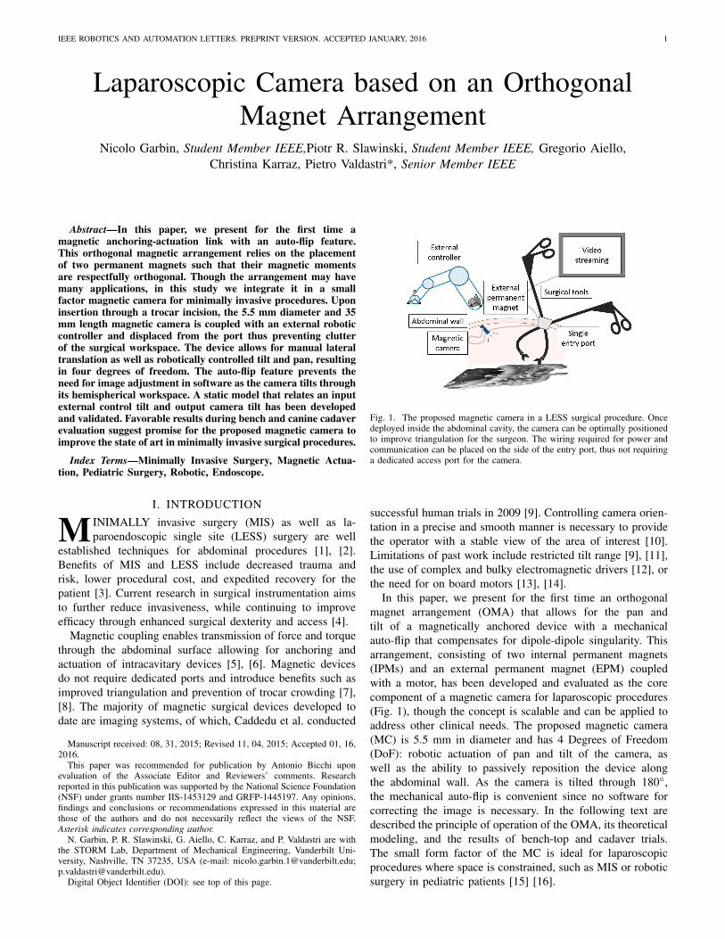
Fig. 1. The proposed magnetic camera in a LESS surgical procedure. Oncedeployed inside the abdominal cavity, the camera can be optimally positionedto improve triangulation for the surgeon. The wiring required for power andcommunication can be placed on the side of the entry port, thus not requiringa dedicated access port for the camera.
successful human trials in 2009 [9]. Controlling camera orien-tation in a precise and smooth manner is necessary to providethe operator with a stable view of the area of interest [10].Limitations of past work include restricted tilt range [9], [11],the use of complex and bulky electromagnetic drivers [12], orthe need for on board motors [13], [14].
In this paper, we present for the first time an orthogonalmagnet arrangement (OMA) that allows for the pan andtilt of a magnetically anchored device with a mechanicalauto-flip that compensates for dipole-dipole singularity. Thisarrangement, consisting of two internal permanent magnets(IPMs) and an external permanent magnet (EPM) coupledwith a motor, has been developed and evaluated as the corecomponent of a magnetic camera for laparoscopic procedures(Fig. 1), though the concept is scalable and can be applied toaddress other clinical needs. The proposed magnetic camera(MC) is 5.5 mm in diameter and has 4 Degrees of Freedom(DoF): robotic actuation of pan and tilt of the camera, aswell as the ability to passively reposition the device alongthe abdominal wall. As the camera is tilted through 180◦,the mechanical auto-flip is convenient since no software forcorrecting the image is necessary. In the following text aredescribed the principle of operation of the OMA, its theoreticalmodeling, and the results of bench-top and cadaver trials.The small form factor of the MC is ideal for laparoscopicprocedures where space is constrained, such as MIS or roboticsurgery in pediatric patients [15] [16].
2 IEEE ROBOTICS AND AUTOMATION LETTERS. PREPRINT VERSION. ACCEPTED JANUARY, 2016
II. MATERIALS AND METHODS
A. Principle of Operation
Typically, magnetic instruments for laparoscopic surgeryconsist of an exterior body that embeds an EPM and anintra-abdominal device that embeds IPM(s) [5], [6], [7], [8],[9], [11], [13], [17]. Referring to Fig. 2.a, magnetic couplingprovides two gross translational DoF and a rotational DoF(pan) that are enabled via manipulation of the EPM: changingXEPM , YEPM , and Γ results in a corresponding variation inXIPMs, YIPMs, and γ.
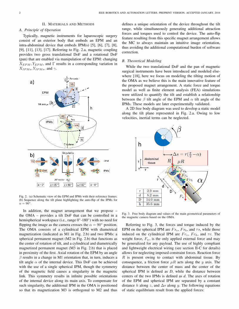
Fig. 2. (a) Schematic view of the EPM and IPMs with their reference frames.(b) Sequence along the tilt plane highlighting the auto-flip of the IPMs forα = 90◦.
In addition, the magnet arrangement that we propose –the OMA – provides a tilt DoF that can be controlled in ahemispherical workspace (i.e., range 0◦-180◦) with no need forflipping the image as the camera crosses the α = 90◦ position.The OMA consists of a cylindrical EPM with diametricalmagnetization (indicated as M1 in Fig. 2.b) and two IPMs: aspherical permanent magnet (M2 in Fig. 2.b) that functions asthe center of rotation of tilt, and a cylindrical and diametricallymagnetized permanent magnet (M3 in Fig. 2.b) that is placedin proximity of the first. Axial rotation of the EPM by an angleβ results in a change in M1 orientation that, in turn, induces atilt angle α of the internal device. This DoF can be achievedwith the use of a single spherical IPM, though the symmetryof the magnetic field causes a singularity in the magneticlink. This symmetry results in infinite possible orientationsof the internal device along its main axis. To compensate forsuch singularity, the additional IPM in the OMA is positionedso that its magnetization M3 is orthogonal to M2 and thus
defines a unique orientation of the device throughout the tiltrange, while simultaneously generating additional attractionforces and torques used to control the device. The auto-flipfeature resulting from this specific magnet arrangement allowsthe MC to always maintain an intuitive image orientation,thus avoiding the additional computational burden of softwarecorrection.
B. Theoretical ModelingWhile the two translational DoF and the pan of magnetic
surgical instruments have been introduced and modeled else-where [18], here we focus on modeling the tilting motion ofthe OMA as we believe this is the main innovative feature ofthe proposed magnet arrangement. A static force and torquemodel as well as finite element analysis (FEA) simulationswere utilized to quantify the tilt and establish a relationshipbetween the β tilt angle of the EPM and α tilt angle of theIPMs. These models are later experimentally validated.
A 2D free body diagram was used to develop a static modelalong the tilt plane represented in Fig. 2.a. Owing to lowvelocities, inertial terms can be neglected.
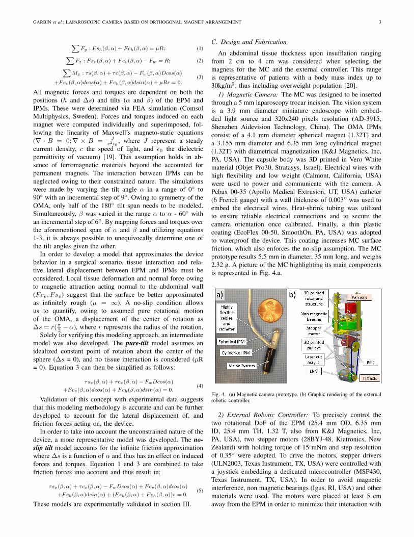
Fig. 3. Free body diagram and values of the main geometrical parameters ofthe magnetic camera based on the OMA.
Referring to Fig. 3, the forces and torque induced by theEPM on the spherical IPM are Fsv , Fsh, and τs, while thoseinduced on the cylindrical IPM are Fcv , Fch, and τc. Theweight force, Fw, is the only applied external force and maybe generalized for any payload. The use of highly compliantand lightweight electrical wiring (see section II-C for details)allows for neglecting imposed constraint forces. Reaction forceR is present owing to contact with abdominal tissue. Byconsequence, a friction force µR acts along the y axis. Thedistance between the center of mass and the center of thespherical IPM is defined as D, while the distance betweencenters of the two IPMs is defined as d. The axes of rotationof the EPM and spherical IPM are separated by a constantdistance h along z, and ∆s along y. The following equationsof static equilibrium result from the applied forces:
GARBIN et al.: LAPAROSCOPIC CAMERA BASED ON ORTHOGONAL MAGNET ARRANGEMENT 3
∑Fy : Fsh(β, α) + Fch(β, α) = µR; (1)∑
Fz : Fsv(β, α) + Fcv(β, α)− Fw = R; (2)∑Mx : τs(β, α) + τc(β, α)− Fw(β, α)Dcos(α)
+Fcv(β, α)dcos(α) + Fch(β, α)dsin(α) + µRr = 0.(3)
All magnetic forces and torques are dependent on both thepositions (h and ∆s) and tilts (α and β) of the EPM andIPMs. These were determined via FEA simulation (ComsolMultiphysics, Sweden). Forces and torques induced on eachmagnet were computed individually and superimposed, fol-lowing the linearity of Maxwell’s magneto-static equations(∇ · B = 0;∇ × B = J
c2ε0, where J represent a steady
current density, c the speed of light, and ε0 the dielectricpermittivity of vacuum) [19]. This assumption holds in ab-sence of ferromagnetic materials beyond the accounted forpermanent magnets. The interaction between IPMs can beneglected owing to their constrained nature. The simulationswere made by varying the tilt angle α in a range of 0◦ to90◦ with an incremental step of 9◦. Owing to symmetry of theOMA, only half of the 180◦ tilt span needs to be modeled.Simultaneously, β was varied in the range α to α - 60◦ withan incremental step of 6◦. By mapping forces and torques overthe aforementioned span of α and β and utilizing equations1-3, it is always possible to unequivocally determine one ofthe tilt angles given the other.
In order to develop a model that approximates the devicebehavior in a surgical scenario, tissue interaction and rela-tive lateral displacement between EPM and IPMs must beconsidered. Local tissue deformation and normal force owingto magnetic attraction acting normal to the abdominal wall(Fcv, Fsv) suggest that the surface be better approximatedas infinitely rough (µ = ∞). A no-slip condition allowsus to quantify, owing to assumed pure rotational motionof the OMA, a displacement of the center of rotation as∆s = r(π2 −α), where r represents the radius of the rotation.
Solely for verifying this modeling approach, an intermediatemodel was also developed. The pure-tilt model assumes anidealized constant point of rotation about the center of thesphere (∆s = 0), and no tissue interaction is considered (µR= 0). Equation 3 can then be simplified as follows:
τsx(β, α) + τcx(β, α)− FwDcos(α)
+Fcv(β, α)dcos(α) + Fch(β, α)dsin(α) = 0.(4)
Validation of this concept with experimental data suggeststhat this modeling methodology is accurate and can be furtherdeveloped to account for the lateral displacement of, andfriction forces acting on, the device.
In order to take into account the unconstrained nature of thedevice, a more representative model was developed. The no-slip tilt model accounts for the infinite friction approximationwhere ∆s is a function of α and thus has an effect on inducedforces and torques. Equation 1 and 3 are combined to takefriction forces into account and thus result in:
τsx(β, α) + τcx(β, α)− FwDcos(α) + Fcv(β, α)dcos(α)
+Fch(β, α)dsin(α) + (Fsh(β, α) + Fch(β, α))r = 0.(5)
These models are experimentally validated in section III.
C. Design and Fabrication
An abdominal tissue thickness upon insufflation rangingfrom 2 cm to 4 cm was considered when selecting themagnets for the MC and the external controller. This rangeis representative of patients with a body mass index up to30kg/m2, thus including overweight population [20].
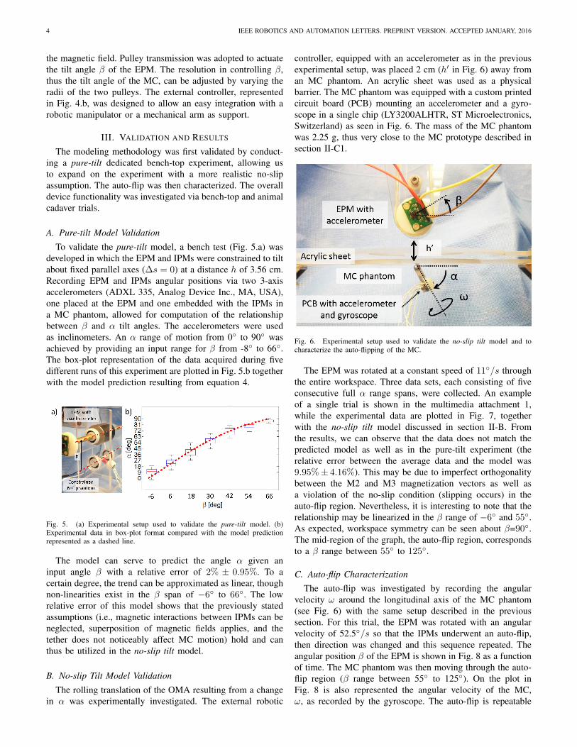
1) Magnetic Camera: The MC was designed to be insertedthrough a 5 mm laparoscopy trocar incision. The vision systemis a 3.9 mm diameter miniature endoscope with embed-ded light source and 320x240 pixels resolution (AD-3915,Shenzhen Aidevision Technology, China). The OMA IPMsconsist of a 4.1 mm diameter spherical magnet (1.32T) anda 3.155 mm diameter and 6.35 mm long cylindrical magnet(1.32T) with diametrical magnetization (K&J Magnetics, Inc,PA, USA). The capsule body was 3D printed in Vero Whitematerial (Objet Pro30, Stratasys, Israel). Electrical wires withhigh flexibility and low weight (Calmont, California, USA)were used to power and communicate with the camera. APebax 00-35 (Apollo Medical Extrusion, UT, USA) catheter(6 French gauge) with a wall thickness of 0.003” was used toembed the electrical wires. Heat-shrink tubing was utilizedto ensure reliable electrical connections and to secure thecamera orientation once calibrated. Finally, a thin plasticcoating (EcoFlex 00-50, SmoothOn, PA, USA) was adoptedto waterproof the device. This coating increases MC surfacefriction, which also enforces the no-slip assumption. The MCprototype results 5.5 mm in diameter, 35 mm long, and weighs2.32 g. A picture of the MC highlighting its main componentsis represented in Fig. 4.a.
Fig. 4. (a) Magnetic camera prototype. (b) Graphic rendering of the externalrobotic controller.
2) External Robotic Controller: To precisely control thetwo rotational DoF of the EPM (25.4 mm OD, 6.35 mmID, 25.4 mm TH, 1.32 T, also from K&J Magnetics, Inc,PA, USA), two stepper motors (28BYJ-48, Kiatronics, NewZealand) with holding torque of 15 mNm and step resolutionof 0.35◦ were adopted. To drive the motors, stepper drivers(ULN2003, Texas Instrument, TX, USA) were controlled witha joystick embedding a dedicated microcontroller (MSP430,Texas Instrument, TX, USA). In order to avoid magneticinterference, non magnetic bearings (Igus, RI, USA) and othermaterials were used. The motors were placed at least 5 cmaway from the EPM in order to minimize their interaction with
4 IEEE ROBOTICS AND AUTOMATION LETTERS. PREPRINT VERSION. ACCEPTED JANUARY, 2016
the magnetic field. Pulley transmission was adopted to actuatethe tilt angle β of the EPM. The resolution in controlling β,thus the tilt angle of the MC, can be adjusted by varying theradii of the two pulleys. The external controller, representedin Fig. 4.b, was designed to allow an easy integration with arobotic manipulator or a mechanical arm as support.
III. VALIDATION AND RESULTS
The modeling methodology was first validated by conduct-ing a pure-tilt dedicated bench-top experiment, allowing usto expand on the experiment with a more realistic no-slipassumption. The auto-flip was then characterized. The overalldevice functionality was investigated via bench-top and animalcadaver trials.
A. Pure-tilt Model Validation
To validate the pure-tilt model, a bench test (Fig. 5.a) wasdeveloped in which the EPM and IPMs were constrained to tiltabout fixed parallel axes (∆s = 0) at a distance h of 3.56 cm.Recording EPM and IPMs angular positions via two 3-axisaccelerometers (ADXL 335, Analog Device Inc., MA, USA),one placed at the EPM and one embedded with the IPMs ina MC phantom, allowed for computation of the relationshipbetween β and α tilt angles. The accelerometers were usedas inclinometers. An α range of motion from 0◦ to 90◦ wasachieved by providing an input range for β from -8◦ to 66◦.The box-plot representation of the data acquired during fivedifferent runs of this experiment are plotted in Fig. 5.b togetherwith the model prediction resulting from equation 4.
Fig. 5. (a) Experimental setup used to validate the pure-tilt model. (b)Experimental data in box-plot format compared with the model predictionrepresented as a dashed line.
The model can serve to predict the angle α given aninput angle β with a relative error of 2% ± 0.95%. To acertain degree, the trend can be approximated as linear, thoughnon-linearities exist in the β span of −6◦ to 66◦. The lowrelative error of this model shows that the previously statedassumptions (i.e., magnetic interactions between IPMs can beneglected, superposition of magnetic fields applies, and thetether does not noticeably affect MC motion) hold and canthus be utilized in the no-slip tilt model.
B. No-slip Tilt Model Validation
The rolling translation of the OMA resulting from a changein α was experimentally investigated. The external robotic
controller, equipped with an accelerometer as in the previousexperimental setup, was placed 2 cm (h′ in Fig. 6) away froman MC phantom. An acrylic sheet was used as a physicalbarrier. The MC phantom was equipped with a custom printedcircuit board (PCB) mounting an accelerometer and a gyro-scope in a single chip (LY3200ALHTR, ST Microelectronics,Switzerland) as seen in Fig. 6. The mass of the MC phantomwas 2.25 g, thus very close to the MC prototype described insection II-C1.
Fig. 6. Experimental setup used to validate the no-slip tilt model and tocharacterize the auto-flipping of the MC.
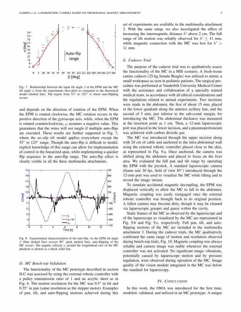
The EPM was rotated at a constant speed of 11◦/s throughthe entire workspace. Three data sets, each consisting of fiveconsecutive full α range spans, were collected. An exampleof a single trial is shown in the multimedia attachment 1,while the experimental data are plotted in Fig. 7, togetherwith the no-slip tilt model discussed in section II-B. Fromthe results, we can observe that the data does not match thepredicted model as well as in the pure-tilt experiment (therelative error between the average data and the model was9.95%± 4.16%). This may be due to imperfect orthogonalitybetween the M2 and M3 magnetization vectors as well asa violation of the no-slip condition (slipping occurs) in theauto-flip region. Nevertheless, it is interesting to note that therelationship may be linearized in the β range of −6◦ and 55◦.As expected, workspace symmetry can be seen about β=90◦.The mid-region of the graph, the auto-flip region, correspondsto a β range between 55◦ to 125◦.
C. Auto-flip Characterization
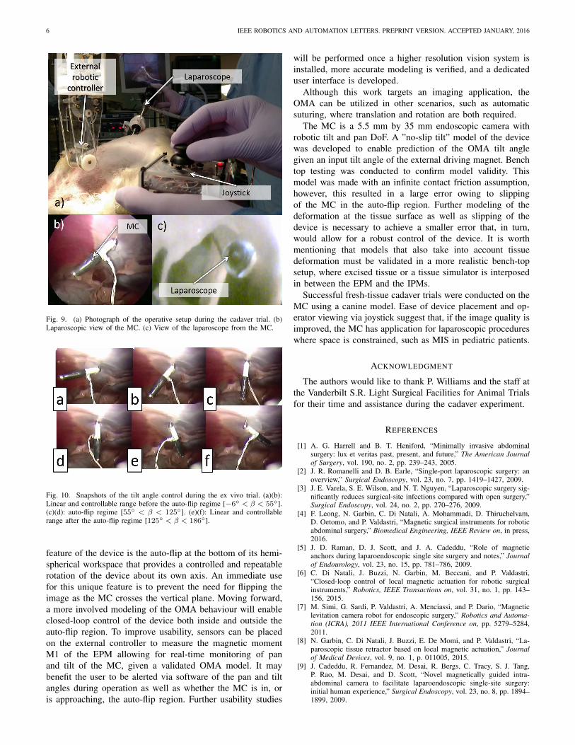
The auto-flip was investigated by recording the angularvelocity ω around the longitudinal axis of the MC phantom(see Fig. 6) with the same setup described in the previoussection. For this trial, the EPM was rotated with an angularvelocity of 52.5◦/s so that the IPMs underwent an auto-flip,then direction was changed and this sequence repeated. Theangular position β of the EPM is shown in Fig. 8 as a functionof time. The MC phantom was then moving through the auto-flip region (β range between 55◦ to 125◦). On the plot inFig. 8 is also represented the angular velocity of the MC,ω, as recorded by the gyroscope. The auto-flip is repeatable
GARBIN et al.: LAPAROSCOPIC CAMERA BASED ON ORTHOGONAL MAGNET ARRANGEMENT 5
Fig. 7. Relationship between the input tilt angle β at the EPM and the MCtilt angle α from the experiments (box-plot) as compared to the theoreticalmodel (dashed line). The region from 55◦ to 125◦ is where auto-flippingoccurs.
and depends on the direction of rotation of the EPM. Whenthe EPM is rotated clockwise, the MC rotation occurs in thepositive direction of the gyroscope axis, while, when the EPMis rotated counterclockwise, ω assumes a negative value. Thisguarantees that the wires will not tangle if multiple auto-flipsare executed. These results are further supported in Fig. 7,where the no-slip tilt model applies everywhere except the55◦ to 125◦ range. Though the auto-flip is difficult to model,explicit knowledge of this range can allow for implementationof control in the linearized span, while implementing a quickerflip sequence in the auto-flip range. The auto-flip effect isclearly visible in all the three multimedia attachments.
Fig. 8. Experimental characterization of the auto-flip. As the EPM tilt angleβ (blue dashed line) crosses 90◦ (pink dashed line), auto-flipping of theMC occurs. The angular velocity ω around the longitudinal axis of the MCphantom is plotted as a black solid line.
D. MC Bench-top Validation
The functionality of the MC prototype described in sectionII-C was assessed by using the external robotic controller witha pulley transmission ratio of 1 and an acrylic sheet as inFig. 6. The motion resolution for the MC was 0.5◦ in tilt and0.35◦ in pan (same resolution as the stepper motor). Examplesof pan, tilt, and auto-flipping motions achieved during this
set of experiments are available in the multimedia attachment2. With the same setup, we also investigated the effect ofincreasing the intermagnetic distance h′ above 2 cm. The fullrange of tilt motion was reliably observed for h′ ≤ 41 mm,while magnetic connection with the MC was lost for h′ >51 mm.
E. Cadaver Trial
The purpose of the cadaver trial was to qualitatively assessthe functionality of the MC in a MIS scenario. A fresh-tissuecanine cadaver (25-kg female Beagle) was utilized to mimic asmall workspace as seen in pediatric patients. The surgical pro-cedure was performed at Vanderbilt University Medical Centerwith the assistance and collaboration of a specially trainedmedical team, in accordance with all ethical considerations andthe regulations related to animal experiments. Two incisionswere made in the abdomen, the first of about 15 mm, placedin the lower quadrant along the anterior axillary line, and thesecond of 5 mm, just inferior to the sub-costal margin, forintroducing the MC. The abdominal thickness was measuredat the insertion point as 1 cm. Then, a 12-mm laparoscopicport was placed in the lower incision, and a pneumoperitoneumwas achieved with carbon dioxide gas.
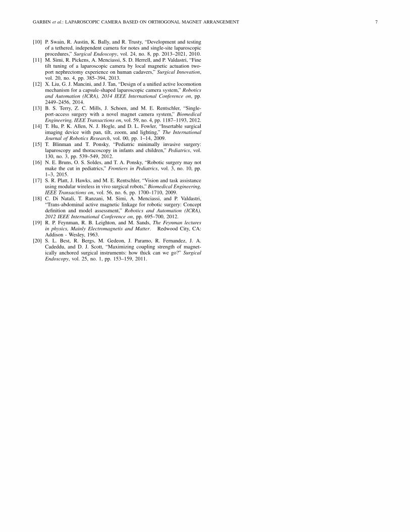
The MC was introduced through the upper incision alongwith 20 cm of cable and anchored to the intra-abdominal wallusing the external robotic controller placed close to the skin,as represented in Fig. 9.a. Once anchored, the camera wasshifted along the abdomen and placed to focus on the liverarea. We evaluated the full pan and tilt range by operatingthe EPM with the joystick. A standard laparoscopic camera(frame rate 30 fps, field of view 85◦) introduced through the12-mm port was used to visualize the MC while tilting and torecord the image stream.
To simulate accidental magnetic decoupling, the EPM wasdisplaced vertically to allow the MC to fall in the abdomen.Magnetic coupling was easily reengaged once the externalrobotic controller was brought back to its original position.A fallen camera may become dirty, though it may be cleanedvia laparoscopic grasper and gauze within the cavity.
Static frames of the MC as observed by the laparoscope andof the laparoscope as visualized by the MC are represented inFig. 9.b and Fig. 9.c, respectively. Full pan, tilt, and auto-flipping motions of the MC are included in the multimediaattachment 3. During the cadaver trials, the MC qualitativelyconfirmed the same range of motion and resolution observedduring bench-top trials, Fig. 10. Magnetic coupling was alwaysreliable and camera image was stable whenever the externalcontroller was not activated. No significant image vibrations,potentially caused by laparoscope motion and by pressureregulation, were observed during operation of the MC. Imagequality of the vision module integrated in the MC was belowthe standard for laparoscopy.
IV. CONCLUSION
In this work, the OMA was introduced for the first time,modeled, validated, and utilized in an MC prototype. A unique
6 IEEE ROBOTICS AND AUTOMATION LETTERS. PREPRINT VERSION. ACCEPTED JANUARY, 2016
Fig. 9. (a) Photograph of the operative setup during the cadaver trial. (b)Laparoscopic view of the MC. (c) View of the laparoscope from the MC.
Fig. 10. Snapshots of the tilt angle control during the ex vivo trial. (a)(b):Linear and controllable range before the auto-flip regime [−6◦ < β < 55◦].(c)(d): auto-flip regime [55◦ < β < 125◦]. (e)(f): Linear and controllablerange after the auto-flip regime [125◦ < β < 186◦].
feature of the device is the auto-flip at the bottom of its hemi-spherical workspace that provides a controlled and repeatablerotation of the device about its own axis. An immediate usefor this unique feature is to prevent the need for flipping theimage as the MC crosses the vertical plane. Moving forward,a more involved modeling of the OMA behaviour will enableclosed-loop control of the device both inside and outside theauto-flip region. To improve usability, sensors can be placedon the external controller to measure the magnetic momentM1 of the EPM allowing for real-time monitoring of panand tilt of the MC, given a validated OMA model. It maybenefit the user to be alerted via software of the pan and tiltangles during operation as well as whether the MC is in, oris approaching, the auto-flip region. Further usability studies
will be performed once a higher resolution vision system isinstalled, more accurate modeling is verified, and a dedicateduser interface is developed.
Although this work targets an imaging application, theOMA can be utilized in other scenarios, such as automaticsuturing, where translation and rotation are both required.
The MC is a 5.5 mm by 35 mm endoscopic camera withrobotic tilt and pan DoF. A ”no-slip tilt” model of the devicewas developed to enable prediction of the OMA tilt anglegiven an input tilt angle of the external driving magnet. Benchtop testing was conducted to confirm model validity. Thismodel was made with an infinite contact friction assumption,however, this resulted in a large error owing to slippingof the MC in the auto-flip region. Further modeling of thedeformation at the tissue surface as well as slipping of thedevice is necessary to achieve a smaller error that, in turn,would allow for a robust control of the device. It is worthmentioning that models that also take into account tissuedeformation must be validated in a more realistic bench-topsetup, where excised tissue or a tissue simulator is interposedin between the EPM and the IPMs.
Successful fresh-tissue cadaver trials were conducted on theMC using a canine model. Ease of device placement and op-erator viewing via joystick suggest that, if the image quality isimproved, the MC has application for laparoscopic procedureswhere space is constrained, such as MIS in pediatric patients.
ACKNOWLEDGMENT
The authors would like to thank P. Williams and the staff atthe Vanderbilt S.R. Light Surgical Facilities for Animal Trialsfor their time and assistance during the cadaver experiment.
REFERENCES
[1] A. G. Harrell and B. T. Heniford, “Minimally invasive abdominalsurgery: lux et veritas past, present, and future,” The American Journalof Surgery, vol. 190, no. 2, pp. 239–243, 2005.
[2] J. R. Romanelli and D. B. Earle, “Single-port laparoscopic surgery: anoverview,” Surgical Endoscopy, vol. 23, no. 7, pp. 1419–1427, 2009.
[3] J. E. Varela, S. E. Wilson, and N. T. Nguyen, “Laparoscopic surgery sig-nificantly reduces surgical-site infections compared with open surgery,”Surgical Endoscopy, vol. 24, no. 2, pp. 270–276, 2009.
[4] F. Leong, N. Garbin, C. Di Natali, A. Mohammadi, D. Thiruchelvam,D. Oetomo, and P. Valdastri, “Magnetic surgical instruments for roboticabdominal surgery,” Biomedical Engineering, IEEE Review on, in press,2016.
[5] J. D. Raman, D. J. Scott, and J. A. Cadeddu, “Role of magneticanchors during laparoendoscopic single site surgery and notes,” Journalof Endourology, vol. 23, no. 15, pp. 781–786, 2009.
[6] C. Di Natali, J. Buzzi, N. Garbin, M. Beccani, and P. Valdastri,“Closed-loop control of local magnetic actuation for robotic surgicalinstruments,” Robotics, IEEE Transactions on, vol. 31, no. 1, pp. 143–156, 2015.
[7] M. Simi, G. Sardi, P. Valdastri, A. Menciassi, and P. Dario, “Magneticlevitation camera robot for endoscopic surgery,” Robotics and Automa-tion (ICRA), 2011 IEEE International Conference on, pp. 5279–5284,2011.
[8] N. Garbin, C. Di Natali, J. Buzzi, E. De Momi, and P. Valdastri, “La-paroscopic tissue retractor based on local magnetic actuation,” Journalof Medical Devices, vol. 9, no. 1, p. 011005, 2015.
[9] J. Cadeddu, R. Fernandez, M. Desai, R. Bergs, C. Tracy, S. J. Tang,P. Rao, M. Desai, and D. Scott, “Novel magnetically guided intra-abdominal camera to facilitate laparoendoscopic single-site surgery:initial human experience,” Surgical Endoscopy, vol. 23, no. 8, pp. 1894–1899, 2009.
GARBIN et al.: LAPAROSCOPIC CAMERA BASED ON ORTHOGONAL MAGNET ARRANGEMENT 7
[10] P. Swain, R. Austin, K. Bally, and R. Trusty, “Development and testingof a tethered, independent camera for notes and single-site laparoscopicprocedures,” Surgical Endoscopy, vol. 24, no. 8, pp. 2013–2021, 2010.
[11] M. Simi, R. Pickens, A. Menciassi, S. D. Herrell, and P. Valdastri, “Finetilt tuning of a laparoscopic camera by local magnetic actuation two-port nephrectomy experience on human cadavers,” Surgical Innovation,vol. 20, no. 4, pp. 385–394, 2013.
[12] X. Liu, G. J. Mancini, and J. Tan, “Design of a unified active locomotionmechanism for a capsule-shaped laparoscopic camera system,” Roboticsand Automation (ICRA), 2014 IEEE International Conference on, pp.2449–2456, 2014.
[13] B. S. Terry, Z. C. Mills, J. Schoen, and M. E. Rentschler, “Single-port-access surgery with a novel magnet camera system,” BiomedicalEngineering, IEEE Transactions on, vol. 59, no. 4, pp. 1187–1193, 2012.
[14] T. Hu, P. K. Allen, N. J. Hogle, and D. L. Fowler, “Insertable surgicalimaging device with pan, tilt, zoom, and lighting,” The InternationalJournal of Robotics Research, vol. 00, pp. 1–14, 2009.
[15] T. Blinman and T. Ponsky, “Pediatric minimally invasive surgery:laparoscopy and thoracoscopy in infants and children,” Pediatrics, vol.130, no. 3, pp. 539–549, 2012.
[16] N. E. Bruns, O. S. Soldes, and T. A. Ponsky, “Robotic surgery may notmake the cut in pediatrics,” Frontiers in Pediatrics, vol. 3, no. 10, pp.1–3, 2015.
[17] S. R. Platt, J. Hawks, and M. E. Rentschler, “Vision and task assistanceusing modular wireless in vivo surgical robots,” Biomedical Engineering,IEEE Transactions on, vol. 56, no. 6, pp. 1700–1710, 2009.
[18] C. Di Natali, T. Ranzani, M. Simi, A. Menciassi, and P. Valdastri,“Trans-abdominal active magnetic linkage for robotic surgery: Conceptdefinition and model assessment,” Robotics and Automation (ICRA),2012 IEEE International Conference on, pp. 695–700, 2012.
[19] R. P. Feynman, R. B. Leighton, and M. Sands, The Feynman lecturesin physics, Mainly Electromagnetis and Matter. Redwood City, CA:Addison - Wesley, 1963.
[20] S. L. Best, R. Bergs, M. Gedeon, J. Paramo, R. Fernandez, J. A.Cadeddu, and D. J. Scott, “Maximizing coupling strength of magnet-ically anchored surgical instruments: how thick can we go?” SurgicalEndoscopy, vol. 25, no. 1, pp. 153–159, 2011.