Embed Size (px)
Citation preview
I F I I
Recognized as an American National Standard (ANSI)
IEEE SM 519-1992 (Revision of IEEE SM 519-1981)
n
IEEE Recommended Practices and Requirements for Harmonic Control in Electrical Power Systems
IEEE Industry Applications Society/ Power Engineering Society CO-sponsored by the Static Power Converter Committee and the Transmission and Distribution Committee
hblkhed by the InSMute of E l m e a l and Ehxtronics Engineers, Inc., 345 East 47th Street, New York, NY loOQ USA.
April 12, 1993 SH 15453
Authorized licensed use limited to: UNIVERSIDADE FEDERAL DO RIO DE JANEIRO. Downloaded on June 8, 2009 at 06:27 from IEEE Xplore. Restrictions apply.
Recognized as an American National Standard (ANSI) 1-
The Institute of Electrical and Electronics Engineers, Inc. 345 East 47th Street, New York, NY 10017-2394, USA
Copyright 0 1993 by the Institute of Electrical and Electronics Engineers, Inc
All rights reserved. Published 1993 Printed in the United States of America
ISBN 1-55937-239-7
No part of this publication may be reproduced in any form, i n an electronic retrieval system or otherwise,
without the prior written permission of the publisher. I
IEEE Std 519-1992
(Revision of IEEE Std 519-1981)
IEEE Recommended Practices and Requirements for Harmonic Control in
Electrical Power Systems
Sponsors
Transmission and Distribution Committee of the
IEEE Power Engineering Society
and
Static Power Converter Committee of the
IEEE Industry Applications Society
Approved June 18,1992
IEEE Standards Board
Approved January 4, 1993
American National Standards Insitute
Abstract: This guide applies to all types of static power converters used in industrial and com- mercial power systems. The problems involved in the harmonic control and reactive compen- sation of such converters are addressed, and an application guide is provided. Limits of disturbances to the ac power distribution system that affect other equipment and communica- tions are recommended. This guide is not intended to cover the effect of radio frequency inter- ference. Keywords: harmonic control, harmonics, reactive power compensation
Authorized licensed use limited to: UNIVERSIDADE FEDERAL DO RIO DE JANEIRO. Downloaded on June 8, 2009 at 06:27 from IEEE Xplore. Restrictions apply.

IEEE Standards documents are developed within the Technical Com- mittees of the IEEE Societies and the Standards Coordinating Commit- tees of the IEEE Standards Board. Members of the committees serve voluntarily and without compensation. They are not necessarily members of the Institute. The standards developed within IEEE represent a con- sensus of the broad expertise on the subject within the Institute as well as those activities outside of IEEE that have expressed an interest in partic- ipating in the development of the standard.
Use of an IEEE Standard is wholly voluntary. The existence of an IEEE Standard does not imply that there are no other ways to produce, test, measure, purchase, market, or provide other goods and services related to the scope of the IEEE Standard. Furthermore, the viewpoint expressed a t the time a standard is approved and issued is subject to change brought about through developments in the state of the art and comments received from users of the standard. Every IEEE Standard is subjected to review a t least every five years for revision or reaffirmation. When a docu- ment is more than five years old and has not been reaffirmed, it is reason- able to conclude that its contents, although still of some value, do not wholly reflect the present state of the art. Users are cautioned to check to determine that they have the latest edition of any IEEE Standard.
Comments for revision of IEEE Standards are welcome from any inter- ested party, regardless of membership affiliation with IEEE. Suggestions for changes in documents should be in the form of a proposed change of text, together with appropriate supporting comments.
Interpretations: Occasionally questions may arise regarding the mean- ing of portions of standards as they relate to specific applications. When the need for interpretations is brought to the attention of IEEE, the Insti- tute will initiate action to prepare appropriate responses. Since IEEE Standards represent a consensus of all concerned interests, it is impor- tant to ensure that any interpretation has also received the concurrence of a balance of interests. For this reason IEEE and the members of its technical committees are not able to provide an instant response to inter- pretation requests except in those cases where the matter has previously received formal consideration.
Comments on standards and requests for interpretations should be addressed to:
Secretary, IEEE Standards Board 445 Hoes Lane P.O. Box 1331 Piscataway, NJ 08855-1331 USA
IEEE Standards documents are adopted by the Institute of Electrical and Electronics Engineers without regard to whether their adoption may involve patents on articles, materials, or processes. Such adoption does not assume any liability to any patent owner, nor does it assume any obligation whatever t o parties adopting the standards documents.
Authorized licensed use limited to: UNIVERSIDADE FEDERAL DO RIO DE JANEIRO. Downloaded on June 8, 2009 at 06:27 from IEEE Xplore. Restrictions apply.
c Foreword
c.
I
(This foreword is not a part of IEEE Std 519-1992, IEEE Recommended Practices and Requirements for Harmonic Control in Electrical Power Systems.)
This recommended practice was prepared by a joint task force sponsored by the Working Group on Power System Harmonics of the Transmission and Distribution Committee of the IEEE Power Engineering Society and the Harmonic and Reactive Compensation Subcommit- tee of the Industrial Power Conversion Committee of the IEEE Industry Applications Society. This recommended practice is an update of the IEEE guide that was published in 1981. The work to revise the guide was started in 1984 and has incorporated the evolving understanding of the effect of static power converters and other nonlinear loads on electric power systems.
This recommended practice recognizes the responsibility that users have not to degrade the voltage of the utility serving other users by requiring nonlinear currents from the utility. It also recognizes the responsibility of the utilities to provide users with close to a sine wave of voltage. The recommended practice suggests guidelines for accomplishing this.
At the time that this standard was completed, the task force had the following membership:
David P. Hartmann, Co-chair (PES) Ray P. Stratford, Co-chair (IAS) C. K. Duffey, Secretary
K. Almon D. L. Ashcroft W. R. Caputo K. R. Chakravarthi H. Chandra W. Dabisza J . Dalton W. K. Davis M. Doyle A. E. Emanuel J. H. Galloway
T. Gentile R. Ghufarian W. M. Grady D. K. Guha M. Higgins W. R. Hodgson S. Ihara S. Kapoor C. E. Johnson T. S. Key J . H. Layne L. Luck
A. Ludbrook M. McGranaghan H. Meyer W. A. Moncrief A. Moore G. Oliver S. Rubino R. J . Schieman J. A. Stewart L. F. Stringer J. K. Winn
At the time that it balloted and approved this standard for submission to the IEEE Stan- dards Board, the balloting group had the following membership:
R. Adapa K. Almon C. J. Amato W. A. Anderson J . Arrillaga D. L. Ashcroft Y. Baghzouz T. M. Barnes B. Berman B. Bhagwat S. K. Biswas W. H. Bixby A. J. Bonner D. W. Borst B. K. Bose J . L. Boyer J . Boyle W. R. Caputo K. R. Chakravarthi H. Chandra D. Y. Chen R. F. Chu W. V. Chumakov W. Dabisza J. Dalton
A. M. Dan W. K. Davis S. Deb R. W. Dedoncker P. H. Desai S. B. Dewan D. M. Divan M. Doyle D. L. Duff M. Ehsani P. Eichin A. El-serafi A. E. Emanuel P. Enjeti P. C. V. Esmeraldo J. D. Fahey W. E. Feero E. F. Fuchs J. H. Galloway T. Gentile A. A. Gigis S. Goldberg T. Gonen M. W. Grady D. C. Griffith
D. K. Guha E. Gunther T. G. Habetler D. P. Hartmann E. A. Harty T. M. Heinrich G. T. Thomas M. Higgins W. R. Hodgson J. Hoffner D. G. Holmes J. Holtz W. F. Horton S. Ihara P. K. Jain W. Jewel1 C. E. Johnson W. C. Jordan S. Kapoor M. J . Kempker T. S. Key P. T. Krein A. Kusko J. S. Lai J. H. Layne
Authorized licensed use limited to: UNIVERSIDADE FEDERAL DO RIO DE JANEIRO. Downloaded on June 8, 2009 at 06:27 from IEEE Xplore. Restrictions apply.
F. C. Lee C. P. Lemone R. D. Lorenz L. Luck A. Ludbrook A. A. Mahmoud L. Malesani J. H. Mallory W. A. Maslowski A. McEachern M. McGranaghan J . C. McIver W. McMurray A. P. S. Meliopoulos N. W. Miller B. J. Min A. Mirbod B. Mokrytzki W. A. Moncrief W. I. Moo A. Moore R. J. Moran J . 0. Ojo T. B. Oliver
T. H. Ortmeyer I. J. Pitel F. S . Prabhakara V. Rajagopalan K. S . Rajashekara S. J . Ranade M. H. Rashid E. W. Reid C. E. Rettig D. D. Robb D. J . Roesler S . Rubino J . T. Salihi M. Samotyj R. G. Schieman D. Dietrich T. Sebastian P. C. Sen A. M. Sharaf R. A. Shinn B. R. Shperling B. R. Sims R. L. Smith W. M. Smith
S. Victor A. C. Stevenson R. P. Stratford L. F. Stringer B.Szabados P. Tenti R. Thallam A.m. Trynadlowski F. G. Turnbull A. K. Upadhyay J. D. Van Wyk S . S . Venkata V. Wagner L. H. Walker D. J . Ward H. W. Wearsch C. A. White J . K. Winn x. xu F. Young J. A. I. Young F. C. Zach D. G. Zimmerman P. D. Ziogas
When the IEEE Standards Board approved this standard on June 18, 1992, it had the fol- lowing membership:
Marco W. Migliaro, Chair Donald C. Loughry, Vice Chair Andrew G. Salem, Secretary
Dennis Bodson Paul L. Borrill Clyde Camp Donald C. Fleckenstein Jay Forster* David F. Franklin Ramiro Garcia Thomas L. Hannan
*Member Emeritus
Donald N. Heirman Ben C. Johnson Walter J. Karplus Ivor N. Knight Joseph Koepfinger* Irving Kolodny D. N. “Jim” Logothetis Lawrence V. McCall
T. Don Michael* John L. Rankine Wallace S. Read Ronald H. Reimer Gary S . Robinson Martin V. Schneider Terrance R. Whittemore Donald W. Zipse
Also included are the following nonvoting IEEE Standards Board liaisons:
Satish K. Aggarwal James Beall
Richard B. Engelman David E. Soffrin
Stanley Warshaw
Adam Sicker IEEE Standards Project Editor
Authorized licensed use limited to: UNIVERSIDADE FEDERAL DO RIO DE JANEIRO. Downloaded on June 8, 2009 at 06:27 from IEEE Xplore. Restrictions apply.

Contents
1.
2.
3.
4.
5.
6.
7.
8.
SECTION PAGE
8.5 Line Notching Calculations (for Low-Voltage Systems) ............................................. 60
Introduction, Scope, and Application. ........................ 1.1 Introduction ........................................................ .................................... 7 1.2 Scope ................................................................. 1.3 Application.. ........................................................ .................................................... 7
References ................................................................................................................................ 8
Definitions and Letter Symbols .............................................................................................. 9 3.1 Definitions ....................................................................................................................... 9 3.2 Letter Symbols .............................................................................................................. 12
Harmonic Generation ........................................................................................................... 14 4.1 Converters .......... .................................................................................................. 14 4.2 Arc Furnaces ...... .................................................................................................. 22 4.3 Static VAFt Comp or .............................................................................................. 23 4.4 Inverters for Dispersed Generation ............................................................................. 23 4.5 Electronic Phase Control ...... ..................................................................... 24 4.6 Cycloconverter Harmonics.. .. ..................................................................... 25 4.7 Switch Mode Power Supplies ........ .................................................. 25 4.8 Pulse Width Modulated (PWM) Drive ........... .......... ........................ 26
System Response Characteristics ............................................. ....... 5.1 General .......................................................................................................................... 27 5.2 Resonant Conditions ..................................................................................................... 28 5.3 Effect of System Loading .............................................................................................. 29 5.4 Typical System Characteristics .................................................................................... 31
Effects of Harmonics .................................................................................................... 35 6.1 General .......................................................................................................................... 35 6.2 Motors and Generators .. .................................................................................. 35 6.3 Transformers ........................................................................... 36 6.4 Power Cables ............. .......................................................................... 37 6.5 Capacitors .................. .......................................................................... 37 6.6 Electronic Equipment ................................................................................................... 38 6.7 Metering .............................................................
.............
6.8 Switchgear and Relaying ................................ ................................................. 39 6.9 Telephone Interference ................ ........................................... 40 6.10 Static Power Converters .............. ........................................... 43
Reactive Power Compensation and Harmonic Control.. ........................................... 44 7.1 Converter Power Factor ..................................... ........................ 44 7.2 Reactive Power Compensation .......................................... 7.3 Control of Harmonic Currents.. .........................
Analysis Methods .......................................................................................... 8.1 Harmonic Current Calculations ........................................................... 8.2 System Frequency Response Calculations ..........................................
8.4 TeleDhone Interference ......................................................................... 8.3 Modeling Guidelines for Harmonic Analysis.. ..................................... ................ 57
Authorized licensed use limited to: UNIVERSIDADE FEDERAL DO RIO DE JANEIRO. Downloaded on June 8, 2009 at 06:27 from IEEE Xplore. Restrictions apply.

SECTION PAGE
8.6 Total Harmonic Distortion ............................................................................................ 63 8.7 System Calculations (Low Voltage. Below 1000 V) ..................................................... 64 8.8 Displacement Power Factor Improvement Calculation .............................................. 65
9 . Measurements ....................................................................................................................... 68 9.1 General .......................................................................................................................... 68 9.2 Basic Equipment Used for the Analysis of Nonsinusoidal
Voltages and Currents .................................................................................................. 68 9.3 Requirements for Instrument Response ...................................................................... 69 9.4 Presentation of Harmonic Data 70 9.5 Transducers for Harmonic Measurements 72
..................................................................... ...................................................
10 . Recommended Practices for Individual Consumers ............................................. 10.1 General ........................................................................................................... 10.2 Development of Current Distortion Limits ................................................. 10.3 Limits on Commutation Notches ........................................ 10.4 Current Distortion Limi 10.5 Flicker .... .....
................ 77 .............................. 77
11 . Recommended Practices for Utilities ........ ........................................................ 83 11.1 General .......................................................................................................................... 83 11.2 Addition of Harmonics .................................................................................................. 83 11.3 Short-Duration Harmonics ........................................................................................... 83 11.4 Abnormal Conditions for Harmonic Problems ............................................................ 84 11.5 Voltage Distortion Limits ............................................................................................. 84 11.6 Limits of Interference With Communication Circuits ................................................ 85
12 . Recommended Methodology for Evaluating New Harmonic Sources ... 12.1 General ............................. ............................ 87 12.2 Identifying Harmonic Analysis Objectives ..... 12.3 Developing Initial System ModeWerform Preliminary Simulations ........................ 87 12.4 Performing Harmonic Measurements .. .............................. 87 12.5 Performing Detailed Simulations ................................................................................. 87 12.6 Developing Solutions to Harmonic Problems .............................................................. 88
13 . Application Examples ........................................................................................................... 89 13.1 Example of Large Industrial Plant Furnished at Transmission Voltage .................. 89 13.2 Example of Several Users on a Single Distribution Feeder ....................................... 90
14 . Bibliography .......................................................................................................................... 99
.
.
Authorized licensed use limited to: UNIVERSIDADE FEDERAL DO RIO DE JANEIRO. Downloaded on June 8, 2009 at 06:27 from IEEE Xplore. Restrictions apply.

IEEE Recommended Practices and Requirements for Harmonic Control in
Electrical Power Systems
1. Introduction, Scope, and Application
1.1 Introduction. The uses of nonlinear loads connected to electric power systems include static power converters, arc discharge devices, saturated magnetic devices, and, to a lesser degree, rotating machines. Static power converters of electric power are the largest nonlinear loads and are used in industry for a variety of purposes, such as electrochemical power sup- plies, adjustable speed drives, and uninterruptible power supplies. These devices are useful because they can convert ac to dc, dc to dc, dc to ac, and ac to ac.
Nonlinear loads change the sinusoidal nature of the ac power current (and consequently the ac voltage drop), thereby resulting in the flow of harmonic currents in the ac power system that can cause interference with communication circuits and other types of equipment. When reactive power compensation, in the form of power factor improvement capacitors, is used with these nonlinear loads, resonant conditions can occur that may result in high levels of harmonic voltage and current distortion when the resonant condition occurs a t a harmonic associated with nonlinear loads.
1.2 Scope. This recommended practice intends to establish goals for the design of electrical systems that include both linear and nonlinear loads. The voltage and current waveforms that may exist throughout the system are described, and waveform distortion goals for the system designer are established. The interface between sources and loads is described as the point of common coupling; and observance of the design goals will minimize interference between elec- trical equipment.
This recommended practice addresses steady-state limitation. Transient conditions exceed- ing these limitations may be encountered. This document sets the quality of power that is to be provided at the point of common coupling. This document does not cover the effects of radio-frequency interference; however, it does include electromagnetic interference with com- munication systems.
1SApplication. This recommended practice is to be used for guidance in the design of power systems with nonlinear loads. The limits set are for steady-state operation and are recom- mended for “worst case” conditions. Transient conditions exceeding these limits may be encountered.
7
Authorized licensed use limited to: UNIVERSIDADE FEDERAL DO RIO DE JANEIRO. Downloaded on June 8, 2009 at 06:27 from IEEE Xplore. Restrictions apply.

IEEE Std 519-1992 IEEE RECOMMENDED PRACTICES AND REQUIREMENTS
2. References
[l] ANSI C34.2-1968 (Withdrawn), American National Standard Recommended Practices and Requirements for Semiconductor Power Rectifiers.'
121 IEEE C57.12.00-1987, IEEE Standard General Requirements for Liquid-Immersed Distri- bution, Power, and Regulating Transformers (ANSI).2
[31 IEEE C57.110-1986, IEEE Recommended Practice for Establishing Transformer Capabil- ity When Supplying Nonsinusoidal Load Currents (ANSI).
[4] IEEE Std 18-1992, IEEE Standard for Shunt Power Capacitors.
[5] IEEE Std 59-1962 (Withdrawn), IEEE Standard for Semiconductor Rectifier component^.^
[61 IEEE Std 100-1992, The New IEEE Standard Dictionary of Electrical and Electronics Terms.
[7] IEEE Std 223-1966 (Withdrawn), IEEE Standard Definitions of Terms for thyristor^.^
181 IEEE Std 368-1977 (Withdrawn), IEEE Recommended Practice for Measurement of Elec- trical Noise and Harmonic Filter Performance of High-Voltage Direct-Current system^.^
[9] IEEE Std 444-1973, IEEE Recommended Practices and Requirements for Thyristor Con- verters and Motor Drives: Part I -Converters for DC Motor Armature Supplies.
[ 101 IEEE Std 469-1988, IEEE Recommended Practice for Voice-Frequency Electrical-Noise Tests of Distribution Transformers (ANSI).
'This standard has been withdrawn; however, copies can be obtained from the Sales Department, American
21EEE publications are available from the Institute of Electrical and Electronics Engineers, Service Center, 445
3This standard has been withdrawn; however, copies can be obtained from the IEEE Standards Department, IEEE
4See Footnote 3. 5See Footnote 3.
National Standards Institute, 11 West 42nd Street, 13th Floor, New York, NY 10036, USA.
Hoes Lane, P.O. Box 1331, Piscataway, NJ 08855-1331, USA.
Service Center, 445 Hoes Lane, P.O. Box 1331, Piscataway, NJ 08855-1331, USA. .-
8
Authorized licensed use limited to: UNIVERSIDADE FEDERAL DO RIO DE JANEIRO. Downloaded on June 8, 2009 at 06:27 from IEEE Xplore. Restrictions apply.

FOR HARMONIC CONTROL IN ELECTRIC POWER SYSTEMS
3. Definitions and Letter Symbols
IEEE Std 519-1992
3.1 Definitions. Definitions given herein are tailored specifically to the harmonics generated by static power converters a t utility system frequencies. Additional useful definitions will be found in IEEE Std 100-1992 [616, IEEE Std 223-1966 [71, IEEE Std 59-1962 [51, ANSI C34.2- 1968 111, and IEEE Std 444-1973 [9].
commutation. The transfer of unidirectional current between thyristor (or diode) converter circuit elements that conduct in succession.
converter. A device that changes electrical energy from one form to another. A semiconductor converter is a converter that uses semiconductors as the active elements in the conversion process.
deviation from a sine wave. A single number measure of the distortion of a sinusoid due to harmonic components. It is equal to the ratio of the absolute value of the maximum difference between the distorted wave and the crest value of the fundamental.
deviation from a sine wave, maximum theoretical. For a nonsinusoidal wave, the ratio of the arithmetic sum of the amplitudes (rms) of all harmonics in the wave to the amplitude (rms) of the fundamental.
distortion factor (harmonic factor). The ratio of the root-mean-square of the harmonic content to the root-mean-square value of the fundamental quantity, expressed as a percent of the fundamental.
' 100% sum of squares of amplitudes of all harmonics square of amplitude of fundamental
D F = /
filter. A generic term used to describe those types of equipment whose purpose is to reduce the harmonic current or voltage flowing in or being impressed upon specific parts of an electri- cal power system, or both.
filter, damped. A filter generally consisting of combinations of capacitors, inductors, and resistors that have been selected in such a way as to present a low impedance over a broad range of frequencies. The filter usually has a relatively low Q (X/R).
filter effectiveness (shunt). Defined by the following two terms:
pf
ps
= the impedance ratio that determines the per unit current that will flow into the shunt filter
= the impedance ratio that determines the per unit current that will flow into the power source
pf should approach unity and ps should be very small a t the tuned frequency.
filter, high-pass. A filter having a single transmission band extending from some cutoff fre- quency, not zero, up to infinite frequency.
6The numbers in brackets correspond to those of the references in Section 3.
9
Authorized licensed use limited to: UNIVERSIDADE FEDERAL DO RIO DE JANEIRO. Downloaded on June 8, 2009 at 06:27 from IEEE Xplore. Restrictions apply.
IEEE Std 519-1992 IEEE RECOMMENDED PRACTICES AND REQUIREMENTS
filter, series. A type of filter that reduces harmonics by putting a high series impedance between the harmonic source and the system to be protected.
filter, shunt. A type of filter that reduces harmonics by providing a low-impedance path to shunt the harmonics from the source away from the system to be protected.
filter, tuned. A filter generally consisting of combinations of capacitors, inductors, and resis- tors that have been selected in such a way as t o present a relative minimum (maximum) impedance to one or more specific frequencies. For a shunt (series) filter, the impedance is a minimum (maximum). Tuned filters generally have a relatively high Q (X/R) .
harmonic. A sinusoidal component of a periodic wave or quantity having a frequency that is an integral multiple of the fundamental frequency.
NOTE: For example, a component, the frequency of which is twice the fundamental frequency, is called a second har- monic.
harmonic, characteristic. Those harmonics produced by semiconductor converter equip- ment in the course of normal operation. In a six-pulse converter, the characteristic harmonics are the nontriple odd harmonics, for example, the 5th, 7th, l l t h , 13th, etc.
h = k q f l k = any integer q = pulse number of converter
harmonic, noncharacteristic. Harmonics that are not produced by semiconductor con- verter equipment in the course of normal operation. These may be a result of beat frequencies; a demodulation of characteristic harmonics and the fundamental; or an imbalance in the ac power system, asymmetrical delay angle, or cycloconverter operation.
harmonic factor. The ratio of the root-sum-square (rss) value of all the harmonics to the root-mean-square (rms) value of the fundamental.
1 2 2 2 2/E3 + E , + E , ... harmonic factor (for voltage) =
El
impedance ratio factor. The ratio of the source impedance, a t the point in the system under consideration, to the equivalent total impedance from the source to the converter circuit ele- ments that commutate simultaneously.
I-T product. The inductive influence expressed in terms of the product of its root-mean- square magnitude ( I ) , in amperes, times its telephone influence factor (TIF).
kV-T product. Inductive influence expressed in terms of the product of its root-mean-square magnitude, in kilovolts, times its telephone influence factor (TIF).
line voltage notch. The dip in the supply voltage to a converter due to the momentary short- circuit of the ac lines during a commutation interval. Alternatively, the momentary dip in sup-
l o
Authorized licensed use limited to: UNIVERSIDADE FEDERAL DO RIO DE JANEIRO. Downloaded on June 8, 2009 at 06:27 from IEEE Xplore. Restrictions apply.

c
FOR HARMONIC CONTROL IN ELECTRIC POWER SYSTEMS IEEE
Std 519-1992
ply voltage caused by the reactive drops in the supply circuit during the high rates of change in currents occurring in the ac lines during commutation.
nonlinear load. A load that draws a nonsinusoidal current wave when supplied by a sinuso- idal voltage source.
notch depth. The average depth of the line voltage notch from the sine wave of voltage.
notch area. The area of the line voltage notch. It is the product of the notch depth, in volts, times the width of the notch measured in microseconds.
power factor, displacement. The displacement component of power factor; the ratio of the active power of the fundamental wave, in watts, t o the apparent power of the fundamental wave, in voltamperes (including the exciting current of the thyristor converter transformer).
power factor, total. The ratio of the total power input, in watts, to the total voltampere input to the converter.
NOTES: (1) This definition includes the effect of harmonic components of current and voltage (distortion power factor), the effect of phase displacement between current and voltage, and the exciting current of the transformer, Volt-amperes are the product of rms voltage and rms current. (2) The power factor is determined a t the ac line terminals of the converter.
pulse number. The total number of successive nonsimultaneous commutations occurring within the converter circuit during each cycle when operating without phase control. I t is also equal to the order of the principal harmonic in the direct voltage, that is, the number of pulses present in the dc output voltage in one cycle of the supply voltage.
quality factor. Two 71 times the ratio of the maximum stored energy t o the energy dissipated per cycle a t a given frequency. An approximate equivalent definition is that the Q is the ratio of the resonant frequency to the bandwidth between those frequencies on opposite sides of the resonant frequency, where the response of the resonant structure differs by 3 dB from that a t resonance. If the resonant circuit comprises an inductance, L , and a capacitance, C, in series with an effective resistance, R, then the value of Q is
short-circuit ratio. For a semiconductor converter, the ratio of the short-circuit capacity of the bus, in MVA, at the point of converter connection to the rating of the converter, in MW.
telephone influence factor (TIF). For a voltage or current wave in an electric supply cir- cuit, the ratio of the square root of the sum of the squares of the weighted root-mean-square values of all the sine-wave components (including alternating current waves both fundamen- tal and harmonic) to the root-mean-square value (unweighted) of the entire wave.
total demand distortion (TDD). The total root-sum-square harmonic current distortion, in percent of the maximum demand load current (15 or 30 min demand).
total harmonic distortion (THD). This term has come into common usage to define either voltage or current “distortion factor.” See: distortion factor.
11
Authorized licensed use limited to: UNIVERSIDADE FEDERAL DO RIO DE JANEIRO. Downloaded on June 8, 2009 at 06:27 from IEEE Xplore. Restrictions apply.

IEEE Std 519-1992 IEEE RECOMMENDED PRACTICES AND REQUIREMENTS
3.2 Letter Symbols. The following set of letter symbols is used in thyristor converter circuit analysis and in the calculation of converter characteristics.
3.2.1 Subscripts
o = 1 = d = h = i - 1 = L = P = pu =
-
s =
a t no load; for example, Edo a t rated load, or fundamental; for example Edl or I I direct current and voltage order of harmonic ideal converter side of transformer, phase-to-phase, el line side of transformer inherent per-unit quantities converter side of transformer, phase-to-neutral
3.2.2 Letter Symbols
a = Y = P = P f = Ps = COS!al =
,
delay angle margin angle (for inverter operation) commutation angle filter impedance ratio source impedance ratio displacement power factor (including transformer exciting current) distortion component of power factor amplitude of sine term for the h harmonic in Fourier expansion (crest value) amplitude of cosine term for the h harmonic in Fourier expansion (crest value) amplitude of resultant for the h harmonic in Fourier expansion (crest value) crest working voltage average direct voltage under load theoretical direct voltage (average direct voltage at no load or light transition load, assuming zero phase control and zero forward voltage drop) direct rated voltage commutating voltage total forward voltage drop per circuit element initial reverse voltage ac system line-to-line voltage ac system line-to-neutral voltage direct-voltage drop caused by resistance losses in transformer equipment, plus interconnections not included in E f transformer dc (secondary) winding line-to-neutral voltage (rms) direct-voltage drop caused by commutating reactance frequency of ac power system I S J E , commutating reactance factor transformer dc winding (secondary) coil rms current average dc load current of the rectifier, in amperes transformer exciting current direct current commutated between two rectifying elements in a single commutat- ing group
12
Authorized licensed use limited to: UNIVERSIDADE FEDERAL DO RIO DE JANEIRO. Downloaded on June 8, 2009 at 06:27 from IEEE Xplore. Restrictions apply.

FOR HARMONIC CONTROL IN ELECTRIC POWER SYSTEMS IEEE
Std 519-1992
,-
THD = v h =
xc =
x c p u = Xcn =
xg =
X L =
XLpu =
xTpu =
zc =
z c n =
z, =
harmonic component of I of the order indicated by the subscript Im
which is the equivalent totalized harmonic component of IL alternating line current (rms) alternating line current (crest value) transformer ac (primary) winding coil current transformer dc winding (secondary) line rms current fundamental component of ZL power component of I1 reactive component of I, inductance of the dc reactor, in henrys number of simple converters pulse number of commutating group transformer load losses, in watts (including resistance and eddy current losses) output power, in watts pulse number of a converter line-to-neutral commutating resistance for a set of commutating groups, in ohms equivalent line-to-neutral commutating resistance, in ohms, for a set of commu- tating groups referred to the ac (primary) winding of a converter transformer line-to-neutral commutating resistance, in ohms, for a single commutating group effective resistance of the ac (primary) winding effective resistance of the direct-current (secondary) winding circuit factor [l for single-way; 2 for bridge (double-way)] total harmonic distortion harmonic component of voltage of the order indicated by the subscript
v,= r CV"h which is the equivalent totalized harmonic component of the voltage line-to-neutral commutating reactance, in ohms, for a set of commutating groups per-unit commutating reactance equivalent line-to-neutral commutating reactance, in ohms, for a set of commutat- ing groups referred to the ac (primary) winding of a converter transformer line-to-neutral commutating reactance, in ohms, for a single commutating group reactance of supply line, in ohms (per line) per-unit reactance of supply line, expressed on base of rated voltamperes at the line terminals of the transformer ac (primary) windings per-unit reactance of transformer, expressed on base of rated voltamperes a t the line terminals of the transformer ac (primary) windings line-to-neutral commutating impedance, in ohms, for a set of commutating groups equivalent line-to-neutral commutating impedance, in ohms, for a set of commu- tating groups referred to the ac (primary) winding of a converter transformer line-to-neutral commutating impedance, in ohms, for a single commutating group
NOTE: Commutating reactances due to various circuit elements may be indicated by subscript as in X,,, X,,, or X,, and X,, for transformers and line, respectively.
Authorized licensed use limited to: UNIVERSIDADE FEDERAL DO RIO DE JANEIRO. Downloaded on June 8, 2009 at 06:27 from IEEE Xplore. Restrictions apply.

IEEE Std 519-1992
-1000 1
IEEE RECOMMENDED PRACTICES AND REQUIREMENTS
4. Harmonic Generation
4.1 Converters. In this text, “ideal” means simplified by ignoring inductance effects in the ac circuit.
4.1.1 Ideal Voltage Wave. Fig 4.1 shows a three-phase power supply system feeding a bridge rectifier. Assuming no load, the highest line-to-line voltage will be connected to the dc load circuit giving the voltage wave form shown in Fig 4.2.
Fig 4.1 Three-phase Bridge Rectifier Circuit
Fig 4.2 Ideal Rectifier Output Wave
14
Authorized licensed use limited to: UNIVERSIDADE FEDERAL DO RIO DE JANEIRO. Downloaded on June 8, 2009 at 06:27 from IEEE Xplore. Restrictions apply.
FOR HARMONIC CONTROL IN ELECTRIC POWER SYSTEMS IEEE
Std 519-1992
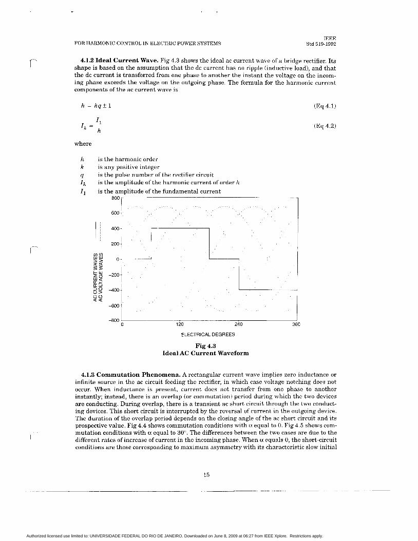
4.1.2 Ideal Current Wave. Fig 4.3 shows the ideal ac current wave of a bridge rectifier. Its shape is based on the assumption that the dc current has no ripple (inductive load), and that the dc current is transferred from one phase to another the instant the voltage on the incom- ing phase exceeds the voltage on the outgoing phase. The formula for the harmonic current components of the ac current wave is
h = k q f l
4 I, = - h
where
h is the harmonic order k is any positive integer q Ih
I,
is the pulse number of the rectifier circuit is the amplitude of the harmonic current of order h is the amplitude of the fundamental current
-~
8oo i
2oo 1 I I
0 0 a < I -600 1
-800 1 0 120 240 3(
ELECTRICAL DEGREES
Fig 4.3 Ideal AC Current Waveform
4.1.3 Commutation Phenomena. A rectangular current wave implies zero
(Eq 4.1)
(Eq 4.2)
0
inductance or I
infinite source in the ac circuit feeding the rectifier, in which case voltage notching does not occur. When inductance is present, current does not transfer from one phase to another instantly; instead, there is an overlap (or commutation) period during which the two devices are conducting. During overlap, there is a transient ac short circuit through the two conduct- ing devices. This short circuit is interrupted by the reversal of current in the outgoing device. The duration of the overlap period depends on the closing angle of the ac short circuit and its prospective value. Fig 4.4 shows commutation conditions with a equal to 0. Fig 4.5 shows com- mutation conditions with a equal to 30". The differences between the two cases are due to the different rates of increase of current in the incoming phase. When a equals 0, the short-circuit conditions are those corresponding to maximum asymmetry with its characteristic slow initial
15
Authorized licensed use limited to: UNIVERSIDADE FEDERAL DO RIO DE JANEIRO. Downloaded on June 8, 2009 at 06:27 from IEEE Xplore. Restrictions apply.

IEEE Std 519-1992 IEEE RECOMMENDED PRACTICES AND REQUIREMENTS
rise. At a equal to go", the short-circuit conditions are those of zero asymmetry with its fast initial rate of rise of current. At this delay angle, the overlap angle is the smallest for a partic- ular value of current. Figs 4.6 and 4.7 show the ac line-to-neutral voltages for the same two cases.
1.5 1
ELECTRICAL DEGREES
Fig 4.4 Commutation Overlap a = 0", p = 25"
ELECTRICAL DEGREES
Fig 4.5 Commutation Overlap a = 30", p = 12'
16
Authorized licensed use limited to: UNIVERSIDADE FEDERAL DO RIO DE JANEIRO. Downloaded on June 8, 2009 at 06:27 from IEEE Xplore. Restrictions apply.

R
c
f-
FOR HARMONIC CONTROL IN ELECTRIC POWER SYSTEMS
n w z e v) 0 W v)
I a a
1
\ .....
2
. . . . . . . . . . . . . . . .
d 9
ELECTRICAL DEGREES
Fig 4.6 Rectifier Voltage Notching a = 0"
ELECTRICAL DEGREES
Fig 4.7 Rectifier Voltage Notching a = 30'
IEEE Std 519-1992
17
I-)
Authorized licensed use limited to: UNIVERSIDADE FEDERAL DO RIO DE JANEIRO. Downloaded on June 8, 2009 at 06:27 from IEEE Xplore. Restrictions apply.
IEEE Std 519-1992
0
IEEE RECOMMENDED PRACTICES AND REQUIREMENTS
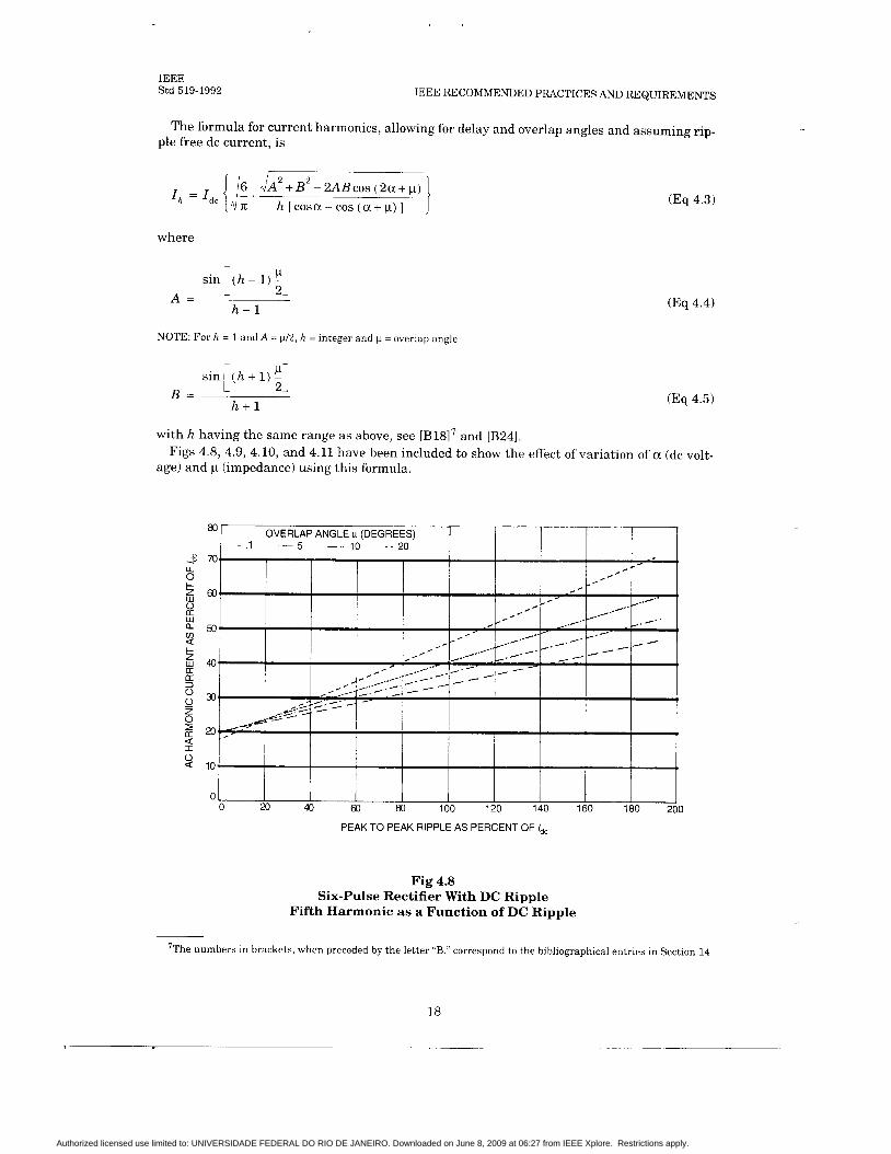
The formula for current harmonics, allowing for delay and overlap angles and assuming rip- ple free dc current, is
I /A2 + B2 - 2ABcos (2a + p) h [ cosa - cos (cc + p) ]
where
sin i ( h - 1) 21 A =
h - 1
NOTE: For h = 1 and A = p/2, h = integer and p = overlap angle
sin [ ( h + 1) 21 B =
h + l
(Eq 4.3)
(Eq 4.4)
(Eq 4.5)
with h having the same range as above, see [B1817 and [B241.
age) and p (impedance) using this formula. Figs 4.8, 4.9, 4.10, and 4.11 have been included to show the effect of variation of a (dc volt-
Fig 4.8 Six-Pulse Rectifier With DC Ripple
Fifth Harmonic as a Function of DC Ripple
7The numbers in brackets, when preceded by the letter “B,” correspond to the bibliographical entries in Section 14.
18
Authorized licensed use limited to: UNIVERSIDADE FEDERAL DO RIO DE JANEIRO. Downloaded on June 8, 2009 at 06:27 from IEEE Xplore. Restrictions apply.

FOR HARMONIC CONTROL IN ELECTRIC POWER SYSTEMS
0
IEEE Std 519-1992
-3 b 5 $
t
I-
w 0 a a
w U: a 3 0 0 z 0
a I 0
2 a
3 b 5 $
Y 5
W
W a
I-
a a 3 0
0
a
!i 2 2 I
50
45
40
35
25
20
15
10
5
0 0 40 60 80 100 120 140 160 180 200
PEAK TO PEAK RIPPLE AS PERCENT OF IdC
Fig 4.9 Six-Pulse Rectifier With DC Ripple
Seventh Harmonic as a Function of DC Ripple
l4 OVERLAP ANGLE p (DEGREES)
-.I . - 5 10 - - 20
PEAK TO PEAK RIPPLE AS PERCENT OF I,,
Fig 4.10 Six-Pulse Rectifier With DC Ripple
Ilth Harmonic as a Function of DC Ripple
19
Authorized licensed use limited to: UNIVERSIDADE FEDERAL DO RIO DE JANEIRO. Downloaded on June 8, 2009 at 06:27 from IEEE Xplore. Restrictions apply.

IEEE Std 519-1992 IEEE RECOMMENDED PRACTICES AND REQUIREMENTS
OVERLAP ANGLE p (DEGREES) 10 1 9, - ,1 .- 5 10 - - 20
I 1 I I I , ,' ,'
/ . I
PEAK TO PEAK RIPPLE AS PERCENT OF I,,
Fig 4.11 Six-Pulse Rectifier With DC Ripple
13th Harmonic as a Function of DC Ripple
4.1.4 Voltage Notching. The voltage notching of the ac voltage wave is caused by the com- mutating action of the rectifier. The ac current wave shape is a result of this notching. Tradi- tionally, the current wave shape is used as the basis for harmonic analysis, and voltage notching is calculated from the I .2 drops of the current harmonics. The depth of the notch a t points nearer to the power source is proportional to the system impedance up to that point. The width of the notch is the commutation angle.
2Ex cosp = 1-- E d o
(Eq 4.6)
(Eq 4.7)
where
X , = system reactance in per unit on converter base
X , I d = dc current in per unit on converter base
= converter transformer reactance in per unit on converter base
4.1.5 Harmonics on the DC Side of a Converter. Any dc load that has a low time con- stant (low inductance), such as a dc motor, does not draw ripple-free current. The harmonics in the voltage wave produce significant ripple currents in the dc current wave. The harmonics are related to the pulse number of the converter circuit: six-pulse, sixth harmonic and 12- pulse, 12th harmonic.
20
Authorized licensed use limited to: UNIVERSIDADE FEDERAL DO RIO DE JANEIRO. Downloaded on June 8, 2009 at 06:27 from IEEE Xplore. Restrictions apply.
FOR HARMONIC CONTROL IN ELECTRIC POWER SYSTEMS
I t I
IEEE Std 519-1992
, , I
I , ,
c
\
\ , \
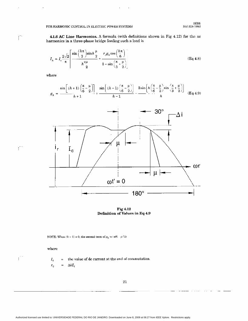
4.1.6 AC Line Harmonics. A formula (with definitions shown in Fig 4.12) for the ac harmonics in a three-phase bridge feeding such a load is
: sin - s i n h p r g h c o s ( F ) 2 +
2P h - 2
(Eq 4.8)
where
sin[ ( h + 1) (i - i)] sin[(h - 1) (i -E)] 2sin[h (i -!)sin (3 + i)] + - (Eq 4.9)
h + l h - 1 h gh =
4 I f 30’ FA i
Fig 4.12 Definition of Values in Eq 4.9
NOTE: When (h - 1) = 0, the second term ofgh is ( d 6 - p / 2 )
where
I , =
rc = AilIc
the value of dc current a t the end of commutation.
21
Authorized licensed use limited to: UNIVERSIDADE FEDERAL DO RIO DE JANEIRO. Downloaded on June 8, 2009 at 06:27 from IEEE Xplore. Restrictions apply.
IEEE Std 519-1992 IEEE RECOMMENDED PRACTICES AND REQUIREMENTS
The characteristic harmonics produced by a static power converter require balanced imped- ances in the ac system and equal firing of the thyristors in the converter. If the firing circuits do not operate symmetrically so that the commutation of each device is not correct, nonchar- acteristic harmonics are produced. These normally are small, but with a parallel resonance at one of them, they can be amplified t o a value that could cause problems.
4.1.7 Phase Multiplication. Harmonics can be reduced by phase multiplication. If m six- pulse rectifier sections
have the same transformer ratios, have transformers with identical impedances, are phase shifted exactly 60/m degrees from each other, are controlled a t exactly the same delay angle, and share the dc load current equally,
then the only harmonics present will be of the order of, hq f. 1, the characteristic harmonics. 6m is called the pulse number and is given the symbol 'q,'see IEEE Std 223-1966 [7].
No two rectifier sections are identical in all these respects. Therefore, in practice, the non- characteristic harmonics will always be present to the degree that the above requirements are not met.
For example, two rectifier sections that are phase shifted by 30" result in 12-pulse, with the minimum harmonic being the 11th; while three rectifiers that are phase shifted 20" result in 18-pulse, with the lowest harmonic being the 17th; and four rectifiers that are phase shifted 15" result in 24-pulse, with the minimum harmonic being the 23rd. ANSI C34.2-1968 [l] gives full details and formulas for many circuit arrangements as well as provides circuit numbers that categorize rectifier circuits.
4.1.8 DC Ripple Current From Sources Independent of the Rectifier. Loads such as adjustable and constant frequency inverters and wound rotor slip recovery systems have sources of dc current ripple independent of the rectifier ripple. These ripple currents some- times are in synchronism with the rectifier and sometimes are not. The ac harmonics due to this type of a load cannot be reduced by phase multiplication. Such loads can produce subhar- monics in the ac circuit.
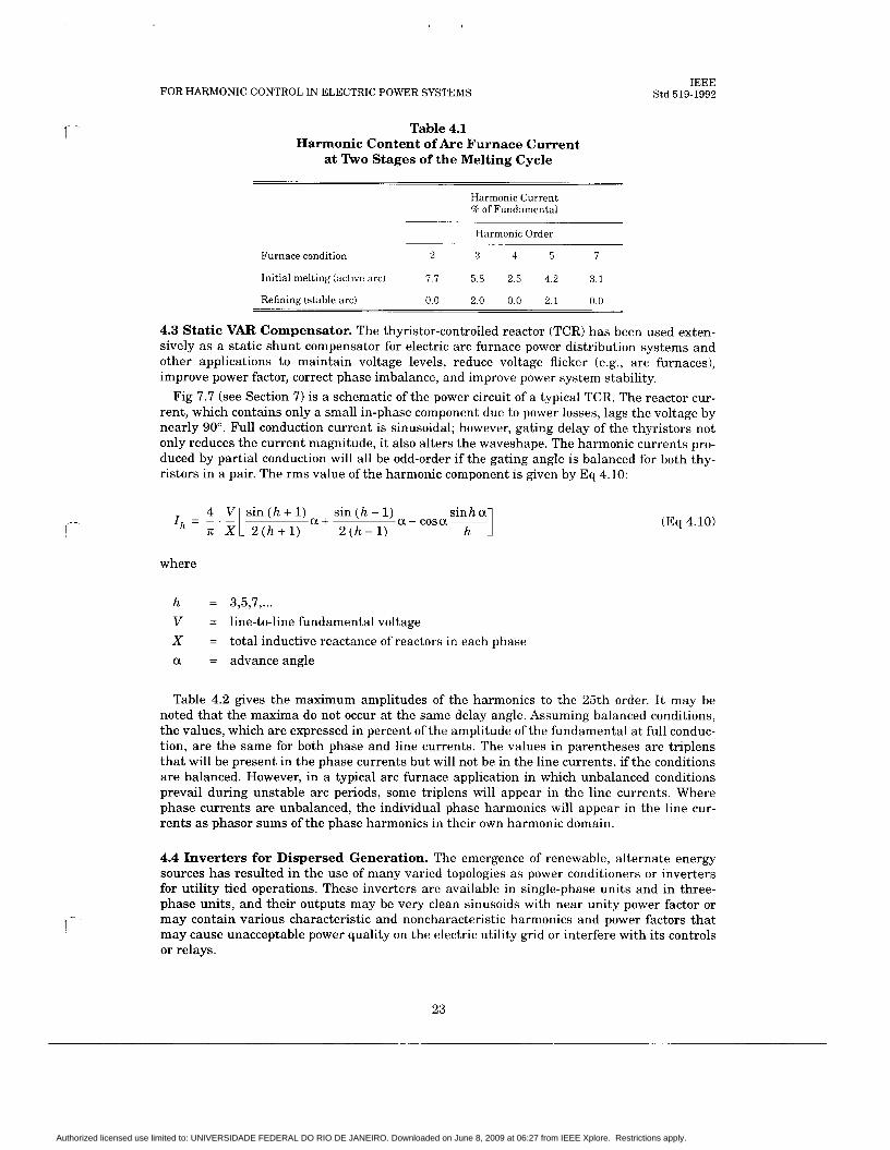
4.2 Arc Furnaces. The harmonics produced by electric arc furnaces used for the production of steel are unpredictable because of the cycle-by-cycle variation of the arc, particularly when boring into new steel scrap. The arc current is nonperiodic, and analysis reveals a continuous spectrum of harmonic frequencies of both integer and noninteger orders. However, harmonic measurements have shown that integer-order harmonic frequencies, particularly low-order starting with the second and ending with the seventh, predominate over the noninteger ones. They have also shown that the amplitude decreases with order. As the pool of molten metal grows, the arc becomes more stable, resulting in much steadier currents with much less dis- tortion and less harmonic activity. The current becomes symmetrical around the zero axis, thus eliminating the even harmonic orders and noninteger harmonics.
Table 4.1 illustrates typical harmonic content of arc furnace current a t two stages of the melting cycle in a typical arc furnace for the production of steel. I t must be emphasized that other furnaces will exhibit somewhat different patterns of harmonic current; but these values may be useful in harmonic studies if more specific data for a particular furnace are not avail- able.
See [B121.
22
Authorized licensed use limited to: UNIVERSIDADE FEDERAL DO RIO DE JANEIRO. Downloaded on June 8, 2009 at 06:27 from IEEE Xplore. Restrictions apply.
FOR HARMONIC CONTROL IN ELECTRIC POWER SYSTEMS IEEE
Std 519-1992
c
r
Table 4.1 Harmonic Content of Arc Furnace Current
at Two Stages of the Melting Cycle
Harmonic Current % of Fundamental
Harmonic Order
Furnace condition 2 3 4 5 7
Initial melting (active arc) 7.7 5.8 2.5 4.2 3.1
Refining (stable arc) 0.0 2.0 0.0 2.1 0.0
4.3 Static VAR Compensator. The thyristor-controlled reactor (TCR) has been used exten- sively as a static shunt compensator for electric arc furnace power distribution systems and other applications to maintain voltage levels, reduce voltage flicker (e.g., arc furnaces), improve power factor, correct phase imbalance, and improve power system stability.
Fig 7.7 (see Section 7) is a schematic of the power circuit of a typical TCR. The reactor cur- rent, which contains only a small in-phase component due to power losses, lags the voltage by nearly 90". Full conduction current is sinusoidal; however, gating delay of the thyristors not only reduces the current magnitude, it also alters the waveshape. The harmonic currents pro- duced by partial conduction will all be odd-order if the gating angle is balanced for both thy- ristors in a pair. The rms value of the harmonic component is given by Eq 4.10:
Q! - COSOL- h
4 V s i n ( h + l ) s in (h -1 ) I Q!+ h - TI: XI 2 ( h + l ) 2 (h - 1)
(Eq 4.10)
where
h = 3,5,7, ... V = line-to-line fundamental voltage X = total inductive reactance of reactors in each phase a = advanceangle
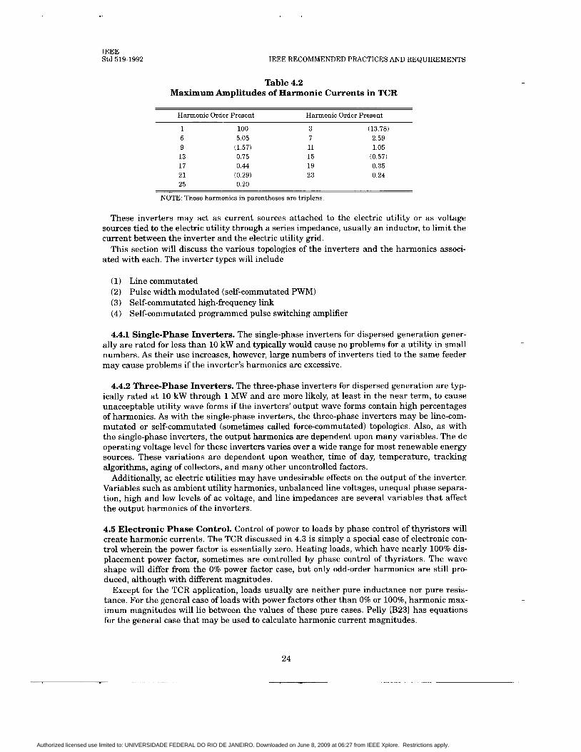
Table 4.2 gives the maximum amplitudes of the harmonics to the 25th order. I t may be noted that the maxima do not occur a t the same delay angle. Assuming balanced conditions, the values, which are expressed in percent of the amplitude of the fundamental at full conduc- tion, are the same for both phase and line currents. The values in parentheses are triplens that will be present in the phase currents but will not be in the line currents, if the conditions are balanced. However, in a typical arc furnace application in which unbalanced conditions prevail during unstable arc periods, some triplens will appear in the line currents. Where phase currents are unbalanced, the individual phase harmonics will appear in the line cur- rents as phasor sums of the phase harmonics in their own harmonic domain.
4.4 Inverters for Dispersed Generation. The emergence of renewable, alternate energy sources has resulted in the use of many varied topologies as power conditioners or inverters for utility tied operations. These inverters are available in single-phase units and in three- phase units, and their outputs may be very clean sinusoids with near unity power factor or may contain various characteristic and noncharacteristic harmonics and power factors that may cause unacceptable power quality on the electric utility grid or interfere with its controls or relays.
Authorized licensed use limited to: UNIVERSIDADE FEDERAL DO RIO DE JANEIRO. Downloaded on June 8, 2009 at 06:27 from IEEE Xplore. Restrictions apply.
IEEE Std 519-1992 IEEE RECOMMENDED PRACTICES AND REQUIREMENTS
Table 4.2 Maximum Amplitudes of Harmonic Currents in TCR
Harmonic Order Present Harmonic Order Present
1 100 5 5.05 9 (1.57) 13 0.75 17 0.44 21 (0.29) 25 0.20
3 7 11 15 19 23
(13.78) 2.59 1.05
(0.57) 0.35 0.24
NOTE: Those harmonics in parentheses are triplens.
These inverters may act as current sources attached to the electric utility or as voltage sources tied to the electric utility through a series impedance, usually an inductor, to limit the current between the inverter and the electric utility grid.
This section will discuss the various topologies of the inverters and the harmonics associ- ated with each. The inverter types will include
(1) Line commutated (2) Pulse width modulated (self-commutated PWM) (3) Self-commutated high-frequency link (4) Self-commutated programmed pulse switching amplifier
4.4.1 Single-phase Inverters. The single-phase inverters for dispersed generation gener- ally are rated for less than 10 kW and typically would cause no problems for a utility in small numbers. As their use increases, however, large numbers of inverters tied to the same feeder may cause problems if the inverter’s harmonics are excessive.
4.4.2 Three-phase Inverters. The three-phase inverters for dispersed generation are typ- ically rated a t 10 kW through 1 MW and are more likely, a t least in the near term, to cause unacceptable utility wave forms if the inverters’ output wave forms contain high percentages of harmonics. As with the single-phase inverters, the three-phase inverters may be line-com- mutated or self-commutated (sometimes called force-commutated) topologies. Also, as with the single-phase inverters, the output harmonics are dependent upon many variables. The dc operating voltage level for these inverters varies over a wide range for most renewable energy sources. These variations are dependent upon weather, time of day, temperature, tracking algorithms, aging of collectors, and many other uncontrolled factors.
Additionally, ac electric utilities may have undesirable effects on the output of the inverter. Variables such as ambient utility harmonics, unbalanced line voltages, unequal phase separa- tion, high and low levels of ac voltage, and line impedances are several variables that affect the output harmonics of the inverters.
4.5 Electronic Phase Control. Control of power to loads by phase control of thyristors will create harmonic currents. The TCR discussed in 4.3 is simply a special case of electronic con- trol wherein the power factor is essentially zero. Heating loads, which have nearly 100% dis- placement power factor, sometimes are controlled by phase control of thyristors. The wave shape will differ from the 0% power factor case, but only odd-order harmonics are still pro- duced, although with different magnitudes.
Except for the TCR application, loads usually are neither pure inductance nor pure resis- tance. For the general case of loads with power factors other than 0% or loo%, harmonic max- imum magnitudes will lie between the values of these pure cases. Pelly [B23] has equations for the general case that may be used to calculate harmonic current magnitudes.
24
Authorized licensed use limited to: UNIVERSIDADE FEDERAL DO RIO DE JANEIRO. Downloaded on June 8, 2009 at 06:27 from IEEE Xplore. Restrictions apply.

r
FOR HARMONIC CONTROL IN ELECTRIC POWER SYSTEMS IEEE
Std 519-1992
4.6 Cycloconverter Harmonics. The expressions for cycloconverter current harmonics are extremely complex. They vary as a function of the frequency ratio of the cycloconverter.
Eq 4.11 shows the frequencies that are present. The first term in the equation represents six-pulse converter components and the second term denotes the converter’s sideband charac- teristic frequencies.
where
f h is the harmonic frequency imposed on the ac system k and n are integers f o is the output frequency of the cycloconverter
4.7 Switch Mode Power Supplies. Most recent electronic equipment use a switch mode power supply to provide the voltage to the equipment. This is an economical power supply that is not affected by minor voltage changes in the power system. It feeds a capacitor that supplies the voltage to the electronic circuitry. Since the load is a capacitor as seen from the power system, the current to the power supply is discontinuous. That is, current flows for only part of the half-cycle. Fig 4.13 shows the current wave form of such a power supply. The har- monic current spectrum of the wave is shown in Table 4.3.
Fig 4.13 Current Wave of Switch Mode Power Supply
Table 4.3 Spectrum of Typical Switch Mode Power Supply
Harmonic Magnitude Harmonic Magnitude
1 1.000 3 0.810 5 0.606 7 0.370
9 11 13 15
0.157 0.024 0.063 0.079
25
Authorized licensed use limited to: UNIVERSIDADE FEDERAL DO RIO DE JANEIRO. Downloaded on June 8, 2009 at 06:27 from IEEE Xplore. Restrictions apply.

IEEE Std 519-1992 IEEE RECOMMENDED PRACTICES AND REQUIREMENTS
4.8 Pulse Width Modulated (PWM) Drive. This dc link drive is different from most static power converter circuits in as much as it has a diode rectifier that gives it a high displacement power factor, but it has a large capacitor on the dc link that regulates the voltage on the dc link. As a result, at light loads (to 30 - 50%), the current only flows when the voltage output of the diode rectifier is above that of the capacitor. At light loads, the current in the ac circuit is discontinuous. Fig 4.14 shows this waveform. It is similar to the switch mode power supply except that it is a three-phase circuit high in fifth harmonic current. As the load on the drive increases, the current becomes continuous. The point a t which the current becomes discontin- uous is determined by the size of the dc link inductance.
I
0 n: 27c
Fig 4.14 Current Wave of PWM Six-Pulse Power Supply
Under Light Load (Discontinuous Current)
26
Authorized licensed use limited to: UNIVERSIDADE FEDERAL DO RIO DE JANEIRO. Downloaded on June 8, 2009 at 06:27 from IEEE Xplore. Restrictions apply.

c
FOR HARMONIC CONTROL IN ELECTRIC POWER SYSTEMS IEEE
Std 519-1992
5. System Response Characteristics
c-
5.1 General. The effect of one or more harmonic sources on a power system will depend pri- marily on the system’s frequency response characteristics. The nonlinear devices described in Section 4 can be represented generally as current sources of harmonics. Therefore, the har- monic voltage distortion on the power system will depend on the impedance vs. frequency characteristics as seen by these current sources.
The system frequency response characteristics are affected by a number of factors. These factors must be considered when performing an analysis for a specific system.
5.1.1 System Short-circuit Capacity. The system short-circuit capacity is an indication of the fundamental frequency system impedance at a point in the system. For simple induc- tive feeders, this is also a measure of the system impedance a t harmonic frequencies when multiplied by the harmonic order. Stiffer systems (higher short-circuit capacities) have lower voltage distortion for the same size harmonic current source than weaker systems (lower short-circuit capacities).
5.1.2 Capacitor Banks and Insulated Cables. Capacitor banks used for voltage control and power factor improvement and insulated cables are major components that affect system frequency response characteristics. The connection of capacitors can cause resonance condi- tions (both series and parallel) that can magnify harmonic levels. The effects of resonance conditions are discussed in 5.2.
Capacitor banks are used as a source of voltage for commutation of some static power con- verters. They can be considered in parallel with the system when calculating the commuta- tion reactance, and thus increase the dildt of commutation.
The line charging capacitances of transmission lines and insulated cables are also in paral- lel with the system inductance. Therefore, they are similar to shunt capacitors with respect to affecting system frequency response characteristics. Usually, capacitor banks are dominant in industrial and overhead distribution systems.
5.1.3 Load Characteristics. The system load has two important effects on the system fre- quency response characteristics:
The resistive portion of the load provides damping that affects the system impedance near resonant frequencies. The resistive load reduces the magnification of harmonic levels near parallel resonance frequencies.
Motor loads and other dynamic loads that contribute to the short-circuit capacity of the system can shift the frequencies a t which resonances occur. These loads appear in par- allel to the system short-circuit inductances when calculating resonant frequencies. Motor loads do not provide significant damping of resonance peaks.
The effect of system loading is discussed in more detail in 5.3.
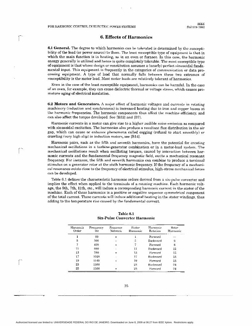
5.1.4 Balanced vs. Unbalanced System Conditions. When system conditions (source strength, capacitor banks, loading, line characteristics, harmonic sources) (e.g., in industrial systems) are completely balanced, positive sequence models can be employed to evaluate sys- tem frequency response characteristics. Under these balanced conditions, the harmonic cur- rents will have sequence characteristics. See Table 6.1.
27
Authorized licensed use limited to: UNIVERSIDADE FEDERAL DO RIO DE JANEIRO. Downloaded on June 8, 2009 at 06:27 from IEEE Xplore. Restrictions apply.

IEEE Std 519-1992 IEEE RECOMMENDED PRACTICES AND REQUIREMENTS
When system conditions are not completely balanced (i.e., in utility distribution and trans- mission systems), unbalanced analysis should be applied. These conditions would include unbalanced harmonic sources on the system, e.g., single-phase sources, single-phase capacitor banks, or unbalanced system loading. In some cases, even the imbalance introduced by untransposed transmission lines can be important. In all of these cases, it is important to use a three-phase system representation for analysis. In these systems, each harmonic has its own positive, negative, and zero-sequence component.
NOTE: A three-phase system representation for studying harmonic responses is required where unbalanced loading and impedances are likely to occur.
5.2 Resonant Conditions. System resonant conditions are the most important factors affecting system harmonic levels. Parallel resonance is a high impedance to the flow of har- monic current, while series resonance is a low impedance to the flow of harmonic current. When resonant conditions are not a problem, the system has the capability to absorb signifi- cant amounts of harmonic currents. It is only when these currents see high impedances due to parallel resonance that significant voltage distortion and current amplification occur. There- fore, it is important to be able to analyze the system frequency response characteristics and to avoid system resonance problems.
Methods of calculating resonant frequencies and overall system frequency response charac- teristics are described in Section 8. The basic circuits resulting in resonance are described here.
5.2.1 Normal Flow of Harmonic Currents. Harmonic currents tend to flow from the nonlinear loads (harmonic sources) toward the lowest impedance, usually the utility source (see Fig 5.1). The impedance of the utility source is usually much lower than parallel paths offered by loads. However, the harmonic current will split depending on the impedance ratios. Higher harmonics will flow to capacitors that are a low impedance to high frequencies.
i h i h ‘h ‘ h __c n- 7r -
Other Loads
Fig 5.1 Normal Flow of Harmonic Currents
5.2.2 Parallel Resonance. Parallel resonance (see Fig 5.2) occurs when the system induc- tive reactance and capacitative reactances are equal a t some frequency. If the combination of capacitor banks and the system inductance result in a parallel resonance near one of the char- acteristic harmonics generated by the nonlinear load, that harmonic current will excite the “tank” circuit, thereby causing an amplified current to oscillate between the energy storage in the inductance and the energy storage in the capacitance. This high oscillating current can cause voltage distortion and telephone interference where the distribution circuit and the telephone circuit are physically proximal.
28
Authorized licensed use limited to: UNIVERSIDADE FEDERAL DO RIO DE JANEIRO. Downloaded on June 8, 2009 at 06:27 from IEEE Xplore. Restrictions apply.
FOR HARMONIC CONTROL IN ELECTRIC POWER SYSTEMS
I c
c
IEEE Std 519-1992
Fig 5.2 Parallel Resonance Condition
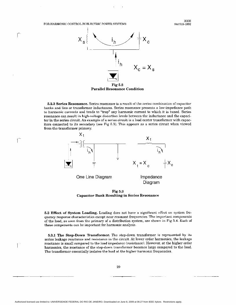
5.2.3 Series Resonance. Series resonance is a result of the series combination of capacitor banks and line or transformer inductances. Series resonance presents a low-impedance path to harmonic currents and tends to “trap” any harmonic current to which it is tuned. Series resonance can result in high-voltage distortion levels between the inductance and the capaci- tor in the series circuit. An example of a series circuit is a load center transformer with capac- itors connected to its secondary (see Fig 5.3). This appears as a series circuit when viewed from the transformer primary.
X t
One Line Diagram
x = x t C
Impedance Diagram
Fig 5.3 Capacitor Bank Resulting in Series Resonance
5.3 Effect of System Loading. Loading does not have a significant effect on system fre- quency response characteristics except near resonant frequencies. The important components of the load, as seen from the primary of a distribution system, are shown in Fig 5.4. Each of these components can be important for harmonic analysis.
5.3.1 The Step-Down Transformer. The step-down transformer is represented by its series leakage reactance and resistance in the circuit. At lower order harmonics, the leakage reactance is small compared to the load impedance (resistance). However, a t the higher order harmonics, the reactance of the step-down transformer becomes large compared to the load. The transformer essentially isolates the load a t the higher harmonic frequencies.
29
Authorized licensed use limited to: UNIVERSIDADE FEDERAL DO RIO DE JANEIRO. Downloaded on June 8, 2009 at 06:27 from IEEE Xplore. Restrictions apply.

IEEE Std 519-1992 IEEE RECOMMENDED PRACTICES AND REQUIREMENTS
Fig 5.4 Load Representation for System Analysis
5.3.2 The Resistive Component. The resistive component of the load becomes very important a t a system resonance. The resistance path (which offers a lower impedance) is taken by harmonics when a parallel resonance exists. Therefore, higher loading levels on the system result in a lower impedance near a parallel resonance. System response with a vary- ing load level is illustrated in Fig 5.5 for a system with a parallel resonance near the fourth harmonic.
n 3 a v
QJ a
10070 Resistive Load 50% Resistive Load 20% Resistive Load ...._...._.__
1 2 3 4 3 6
Harmonic Number
Fig 5.5 System Response Illustrating the Effect of Resistive Load
on Parallel Resonance Peak
30
Authorized licensed use limited to: UNIVERSIDADE FEDERAL DO RIO DE JANEIRO. Downloaded on June 8, 2009 at 06:27 from IEEE Xplore. Restrictions apply.

FOR HARMONIC CONTROL IN ELECTRIC POWER SYSTEMS IEEE
Std 519-1992
c 5.3.3 The Motor Component. Motor load appears primarily inductive at harmonic fre- quencies. The correct representation for motors a t harmonic frequencies is the short-circuit impedance (locked rotor, subtransient). This inductance does not provide significant damping of resonance peaks; but it will shift the resonant frequency somewhat because it is essentially in parallel with the source inductance. This is important if the resonance is close to a problem harmonic - changes in the motor load on the system can shift the resonance to the harmonic frequency. Motor load is particularly important on industrial systems and on commercial and residential distribution systems with a high percentage of air conditioning load, in which motor load is a significant portion of the total system load.
5.4 Typical System Characteristics. It is very difficult to develop any typical system fre- quency response characteristics because of the number of factors affecting the response. How- ever, it is worthwhile to look at some basic characteristics for different types of systems and the causes of these characteristics. These basic characteristics, along with the calculating techniques described in Section 8, can be used to determine whether or not more detailed analysis is required for a specific system.
5.4.1 Distribution Systems. Distribution system frequency response characteristics are dominated by the interaction between shunt capacitance and the system inductances (as shown in Fig 5.6). The damping provided by system loads is important. Besides capacitor banks, the capacitance of insulated cables can influence system resonances.
XL XL XL
Fig 5.6 Typical Distribution System Characteristic
Most severe resonant conditions occur when a single large capacitor bank is the primary means of shunt compensation on the system (a large capacitor bank at the substation, for instance). In this case, there is one resonant point on the system, and significant voltage dis- tortion and magnification of harmonic currents can occur if this resonance corresponds to a harmonic current generated by nonlinear loads. I t is quite common for this resonance to occur near the fifth harmonic, as is the case for the frequency response characteristics illustrated in Fig 5.5.
When a number of smaller capacitor banks are applied throughout the distribution system, there will be a number of different resonant frequencies. If these capacitors are switched, the resonant characteristic of the system becomes more difficult to determine. Each of the reso- nances generally will have magnitudes that are less than the magnitudes that would be asso- ciated with one major resonance. Therefore, the effect of distributing the capacitors around the system may reduce the potential for problems due to a major resonance. The placement of a capacitor introduces an additional parallel resonance that could interact with harmonic cur- rents. The harmonic voltage distortion generally is worse when capacitors are in service near the feeder extremities, resulting in a larger inductance from the line, which tunes the reso- nances to lower frequencies and increases the distance the harmonic currents will flow.
31
Authorized licensed use limited to: UNIVERSIDADE FEDERAL DO RIO DE JANEIRO. Downloaded on June 8, 2009 at 06:27 from IEEE Xplore. Restrictions apply.

IEEE Std 519-1992 IEEE RECOMMENDED PRACTICES AND REQUIREMENTS
As mentioned previously, damping provided by loads is very important on distribution sys- tems. This is often the factor that prevents resonant conditions from causing significant har- monic problems. The resistive component of the load is the most important factor.
Balanced system analysis does not apply in many cases. However, it does provide useful information in cases with large three-phase harmonic sources or in cases in which phase loca- tion of single-phase loads are not known. Any of the following conditions can result in the need to analyze the distribution system response with a full three-phase representation:
(1) Large single-phase harmonic sources (nonlinear loads) (2) Significantly unbalanced load characteristics (3) Single-phase capacitor banks on the system
NOTE: Unbalanced analysis requires that the (a-b-c) phase to which any single-phase loads and capacitors are con- nected be known.
5.4.2 Industrial Systems. Industrial power systems resemble compact distribution sys- tems (see example in Fig 5.71, with a few very important differences:
The frequency response usually is dominated by relatively large capacitor banks and the short-circuit inductance. The associated resonance is often near lower order har- monics due to the power factor characteristics of industrial loads. The line and cable impedances are often negligible. The percentage of harmonic producing load,. often is higher than for distribution sys- tems. In fact, the major loads may be nonlinear devices (e.g., rectifiers, arc furnaces, adjustable-speed drives, etc.). There often is very little resistive-type load to provide damping near the resonant fre- quency. This results in more severe harmonic distortion if the resonance is near a gen- erated harmonic. Motor loads are important in that they shift the resonant frequencies. Most industrial systems can be analyzed with a balanced representation. The loads generally are balanced three-phase loads (including the harmonic sources), and three- phase capacitor banks are used.
Utility Source
Motors
Loads Loads Loads
Fig 5.7 Typical Industrial Power System
32
Authorized licensed use limited to: UNIVERSIDADE FEDERAL DO RIO DE JANEIRO. Downloaded on June 8, 2009 at 06:27 from IEEE Xplore. Restrictions apply.

FOR HARMONIC CONTROL IN ELECTRIC POWER SYSTEMS IEEE
Std 519-1992
5.4.3 Transmission Systems. Transmission system frequency response characteristics are very complicated and are virtually impossible to generalize. Unlike industrial systems, the transmission system line and cable capacitances cannot be ignored in the analysis. These capacitances are important and determine the system resonances. Long line hyperbolic equa- tions must be applied to the lines and cables to determine the correct representation at har- monic frequencies. Line transposition must be taken into account.
It is becoming more and more common to apply large capacitors at transmission voltage lev- els. These capacitor banks have a dramatic effect on the frequency response characteristics. When they are switched, the resonant characteristic of the system changes.
Transmission system harmonic analysis requires very extensive system representations because of the many paths available for the harmonic currents to flow. Analysis without a computer program is nearly impossible. Even with a computer program, it is very difficult to predict system response because of changing system characteristics and the unknowns in the model.
&€- - 5.11
10 AMP INJECTION AT ZERO DEGREES
2.92 11255 230 KV l -
3.91 11731 3.91 -h &
2.91 1 1
1 . 6 8 w 1.68 4.82- 4.82 (-180 A -- c_
4.25 - 1 TI
8.45 11537
5.36
3.60 &
Fig 5.8 Fif th Harmonic Current Flowing in a Transmission
Network due to a 10 A Injection at Bus 7
33
4.56
1
Authorized licensed use limited to: UNIVERSIDADE FEDERAL DO RIO DE JANEIRO. Downloaded on June 8, 2009 at 06:27 from IEEE Xplore. Restrictions apply.

IEEE Std 519-1992 IEEE RECOMMENDED PRACTICES AND REQUIREMENTS
One of the most important elements in the transmission system representation is the load model. (In terms of the transmission system, the load is defined as not only including indus- trial plants connected to the transmission system, but also including the utility distribution system. All of the various inductances and capacitances contribute t o this load model.) Because the correct load representation is not fixed, the frequency response predictions for transmission systems cannot be considered very accurate unless the model includes the distri- bution feeder level.
An example of predicted harmonic current flows in a transmission system is provided in Fig 5.8. This figure illustrates the complexity of the current flows, even for a very simple system.
Simulations of transmission system frequency response characteristics should be used to provide a wide range of possible system characteristics. Important parameters, such as load and capacitor banks, should be varied to determine their effects. Also, a number of different system contingency conditions should be analyzed. With a lack of better information, a worst- case analysis can be performed using this range of system characteristics. The range of char- acteristics can also be used for filter design purposes, if harmonic levels are unacceptable. The large shunt capacitance of the lines usually causes the characteristic system resonant fre- quency t o be between the fifth and the 13th harmonic.
34
Authorized licensed use limited to: UNIVERSIDADE FEDERAL DO RIO DE JANEIRO. Downloaded on June 8, 2009 at 06:27 from IEEE Xplore. Restrictions apply.
FOR HARMONIC CONTROL IN ELECTRIC POWER SYSTEMS IEEE
Std 519-1992
6. Effects of Harmonics
c
6.1 General. The degree to which harmonics can be tolerated is determined by the suscepti- bility of the load (or power source) to them. The least susceptible type of equipment is that in which the main function is in heating, as in an oven or furnace. In this case, the harmonic energy generally is utilized and hence is quite completely tolerable. The most susceptible type of equipment is that whose design or constitution assumes a (nearly) perfect sinusoidal funda- mental input. This equipment is frequently in the categories of communication or data pro- cessing equipment. A type of load that normally falls between these two extremes of susceptibility is the motor load. Most motor loads are relatively tolerant of harmonics.
Even in the case of the least susceptible equipment, harmonics can be harmful. In the case of an oven, for example, they can cause dielectric thermal or voltage stress, which causes pre- mature aging of electrical insulation.
6.2 Motors and Generators. A major effect of harmonic voltages and currents in rotating machinery (induction and synchronous) is increased heating due to iron and copper losses a t the harmonic frequencies. The harmonic components thus affect the machine efficiency, and can also affect the torque developed. See [B32] and [B7].
Harmonic currents in a motor can give rise to a higher audible noise emission as compared with sinusoidal excitation. The harmonics also produce a resultant flux distribution in the air gap, which can cause or enhance phenomena called cogging (refusal to start smoothly) or crawling (very high slip) in induction motors, see [B14].
Harmonic pairs, such as the fifth and seventh harmonics, have the potential for creating mechanical oscillations in a turbine-generator combination or in a motor-load system. The mechanical oscillations result when oscillating torques, caused by interaction between har- monic currents and the fundamental frequency magnetic field, excite a mechanical resonant frequency. For instance, the fifth and seventh harmonics can combine to produce a torsional stimulus on a generator rotor a t the sixth harmonic frequency. If the frequency of a mechani- cal resonance exists close to the frequency of electrical stimulus, high-stress mechanical forces can be developed.
Table 6.1 defines the characteristic harmonic orders derived from a six-pulse converter and implies the effect when applied to the terminals of a rotating machine. Each harmonic volt- age, the 5th, 7th, llth, etc., will induce a corresponding harmonic current in the stator of the machine. Each of these harmonics is a positive or negative sequence symmetrical component of the total current. These currents will induce additional heating in the stator windings, thus adding to the temperature rise caused by the fundamental current.
Table 6.1 Six-Pulse Converter Harmonic
Harmonic Frequency Sequence Stator Harmonic Rotor Order Hz Network Harmonic Rotation Harmonic
1 60 + 1 Forward -
5 300 5 Backward 6 7 420 + 7 Forward 6 11 660 11 Backward 12 13 780 + 13 Forward 12 17 1020 17 Backward 18 19 1140 + 19 Forward 18 23 1380 23 Backward 24 25 1500 i 25 Forward 24
35
Authorized licensed use limited to: UNIVERSIDADE FEDERAL DO RIO DE JANEIRO. Downloaded on June 8, 2009 at 06:27 from IEEE Xplore. Restrictions apply.

IEEE Std 519-1992 IEEE RECOMMENDED PRACTICES AND REQUIREMENTS
Another generally greater concern is the flow of harmonic currents in the rotor, see [B7]. The flow of each current in the stator will produce a magnetomotive force in the air gap that will induce current flow in the rotor of the machine. Just as each characteristic harmonic can be defined as being a positive or negative sequence, the rotation of that harmonic will be either forward or backward with respect to rotor rotation. The fifth harmonic will rotate in a backward direction (negative sequence), so a harmonic current will be induced in the rotor with a frequency corresponding to the net rotational difference between the fundamental air gap frequency and the fifth, i.e., the fifth plus one, or the sixth harmonic. Since the seventh harmonic will rotate in a forward direction (positive sequence), a harmonic current will be induced in the rotor with a frequency corresponding to the net rotational difference between the seventh and the fundamental air gap frequency, i.e., the seventh minus one, or the sixth harmonic. Thus, from a rotor heating standpoint, the fifth and the seventh harmonics in the stator combine to produce a sixth harmonic current in the rotor. The 11th and the 13th har- monics act in the same manner to produce the 12th harmonic current in the rotor, and so on with higher order harmonic pairs. There are two major concerns with these rotor harmonics:
(1) Resultant rotor heating (2) Pulsating or reduced torques
The amount of rotor heating that can be tolerated, as well as the amount that is incurred in a given case, depends on the type of rotor involved. Wound-rotor machinery is more likely to be more seriously affected than squirrel-cage rotor machinery, and deep bar squirrel-cage rotors are more affected than ordinary squirrel cages, see [B71 and [B251. Winding losses gen- erally are of more concern than iron losses. The sum effect of the harmonics is a reduction in efficiency and life of the machinery. Neither reduction is pronounced for normally encountered harmonic content, but the harmonic heating typically reduces performance to 90-95% of that which would be experienced with pure fundamental sine waves applied, see [B71 and [B12].
“Normally encountered harmonic content,” as used in the previous statement, refers to the values cited in Table 11.1. These statements apply to application of motors on distribution systems having allowable harmonic content. They specifically do not apply to the rating of a motor that is to be driven by an adjustable-frequency inverter, for instance. Cummings [B7] concludes that a typical 1.0 service factor induction motor would suffer less under the condi- tions of Table 11.1 than it would while running at rated load with supply voltage increased (or decreased) by 10%. Cummings, see [B71, provides a detailed method of estimating harmonic loses and heating in cases in which more precise information is required.
As noted above, the harmonics can also cause a pulsating torque output. This can affect product quality where motor loads are sensitive to such variations, e.g., in some synthetic fiber spinning or some metal working applications. In cases in which substantial inertia is coupled to the rotor shaft, e.g., in a motor-generator or engine-generator, the electrical har- monics can excite a mechanical resonance. The resulting mechanical oscillations can cause shaft fatigue and accelerated aging of the shaft and connected mechanical parts.
6.3 Transformers. With the exception that harmonics applied to transformers may result in i-ncreased audible noise, the effects on these components usually are those arising from para- sitic heating.
The effect of harmonics on transformers is twofold: current harmonics cause an increase in copper losses and stray flux losses, and voltage harmonics cause an increase in iron losses. The overall effect is an increase in the transformer heating, as compared to purely sinusoidal (fundamental) operation.
IEEE C57.12.00-1987 [21 proposes a limit on the harmonics in transformer current. The upper limit of the current distortion factor is 5% a t rated current. The recommended practice also gives the maximum rms overvoltages that the transformer should be able to withstand in the steady state: 5% a t rated load and 10% at no load. The harmonic currents in the applied voltage must not result in a total rms voltage exceeding these ratings.
36
Authorized licensed use limited to: UNIVERSIDADE FEDERAL DO RIO DE JANEIRO. Downloaded on June 8, 2009 at 06:27 from IEEE Xplore. Restrictions apply.

FOR HARMONIC CONTROL IN ELECTRIC POWER SYSTEMS IEEE
Std 519-1992
r
r
r
It should be noted that the transformer losses caused by both harmonic voltages and har- monic currents are frequency dependent. The losses increase with increasing frequency and, therefore, higher frequency harmonic components can be more important than lower fre- quency components in causing transformer heating. As discussed in Section 4, in general, the higher frequency harmonics occur with diminished amplitude, which tends to cancel their greater effect. However, as also noted in Section 4, a given actual situation may exhibit unex- pectedly high amplitudes for certain higher frequencies. IEEE (257.110-1986 [31 furnishes fur- ther guidelines relative to expected effects.
Transformer losses may be segregated into load losses and no load losses. Load loss may be further divided by 12R (winding losses) and stray losses. Stray losses are of special importance when evaluating the added heating due to the effect of a nonsinusoidal current waveform.
Stray losses are eddy-current losses due to stray electromagnetic flux in the windings, core, core clamps, magnetic shields, tank wall, and other structural parts of the transformer. The winding stray loss includes winding conductor strand eddy-current loss and the loss due to circulating currents between strands or parallel winding circuits. This loss will rise in propor- tion to the square of the load current and the square of frequency. The temperature will also rise in the structural parts because of eddy currents, again approximately as the square of the load current and the square of the frequency.
IEEE C57:llO-1986 [31 provides a calculation procedure to obtain the eddy-current loss for a given transformer.
6.4 Power Cables. Cables involved in system resonance, as described in 5.1.2, may be sub- jected to voltage stress and corona, which can lead to dielectric (insulation) failure. Cables that are subjected to “ordinary” levels of harmonic current are prone to heating.
The flow of nonsinusoidal current in a conductor will cause additional heating over and above what would be expected for the rms value of the wave form. This is due to two phenom- ena known as “skin effect” and “proximity effect,” both of which vary as a function of fre- quency as well as conductor size and spacing. As a result of these two effects, the effective ac resistance, RAC, is raised above the dc resistance, RDc, especially for larger conductors. When a current waveform that is rich in high-frequency harmonics is flowing in a cable, the equiva- lent RAC for the cable is raised even higher, amplifylng the 12RAc loss.
Typical capacity derating curves have been plotted for a number of cable sizes, as shown in Fig 6.1 for a six-pulse harmonic distribution. See [B251.
It can be seen from Fig 6.1 that the effect of harmonic heating in cables normally is not a matter of great concern. Prudent design should, however, provide the required derating.
6.5 Capacitors. A major concern arising from the use of capacitors in a power system is the possibility of system resonance. This effect (considered in detail in 5.1) imposes voltages and currents that are considerably higher than would be the case without resonance.
The reactance of a capacitor bank decreases with frequency, and the bank, therefore, acts as a sink for higher harmonic currents. This effect increases the heating and dielectric stresses. Frequent switching of nonlinear magnetic components (e.g., iron core), such as transformers and reactors, can produce harmonic currents that will add to the loading of capacitors.
IEEE Std 18-1992 [4] gives limitations on voltage, current, and reactive power for capacitor banks. These can be used to determine the maximum allowable harmonic levels.
The result of the increased heating and voltage stress brought about by harmonics is a shortened capacitor life.
Although the previous discussion is intended to describe effects in power distribution appa- ratus such as power factor improvement or harmonic filter capacitors, it should be noted that other capacitors can be affected as well. For instance, the capacitors used in capacitor-run sin- gle-phase motors, or those used in rectifier snubber circuits, will be subject to similar thermal and voltage stresses.
Authorized licensed use limited to: UNIVERSIDADE FEDERAL DO RIO DE JANEIRO. Downloaded on June 8, 2009 at 06:27 from IEEE Xplore. Restrictions apply.
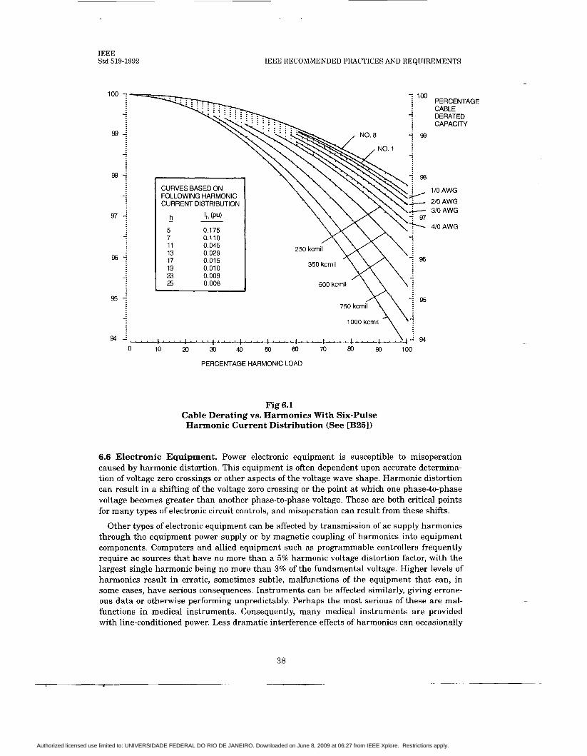
IEEE Std 519-1992 IEEE RECOMMENDED PRACTICES AND REQUIREMENTS
100 7
CURVES BASED ON FOLLOWING HARMON IC CURRENT DISTRIBUTION
h Ih (PU) - 5 0.175 7 0.110 11 0.045 13 0.029 17 0.015 19 0.01 0 23 0.009 25 0.008
PERCENTAGE CABLE DERATED CAPACITY
1 IO AWG
210 AWG 310 AWG
410 AWG
Fig 6.1 Cable Derating vs. Harmonics With Six-Pulse Harmonic Current Distribution (See [B251)
6.6 Electronic Equipment. Power electronic equipment is susceptible to misoperation caused by harmonic distortion. This equipment is often dependent upon accurate determina- tion of voltage zero crossings or other aspects of the voltage wave shape. Harmonic distortion can result in a shifting of the voltage zero crossing or the point at which one phase-to-phase voltage becomes greater than another phase-to-phase voltage. These are both critical points for many types of electronic circuit controls, and misoperation can result from these shifts.
Other types of electronic equipment can be affected by transmission of ac supply harmonics through the equipment power supply or by magnetic coupling of harmonics into equipment components. Computers and allied equipment such as programmable controllers frequently require ac sources that have no more than a 5% harmonic voltage distortion factor, with the largest single harmonic being no more than 3% of the fundamental voltage. Higher levels of harmonics result in erratic, sometimes subtle, malfunctions of the equipment that can, in some cases, have serious consequences. Instruments can be affected similarly, giving errone- ous data or otherwise performing unpredictably. Perhaps the most serious of these are mal- functions in medical instruments. Consequently, many medical instruments are provided with line-conditioned power. Less dramatic interference effects of harmonics can occasionally
38
Authorized licensed use limited to: UNIVERSIDADE FEDERAL DO RIO DE JANEIRO. Downloaded on June 8, 2009 at 06:27 from IEEE Xplore. Restrictions apply.

FOR HARMONIC CONTROL IN ELECTRIC POWER SYSTEMS IEEE
Std 519-1992
f
be observed in radio and television equipment, as well as in video recorders and audio repro- duction systems.
Since most electronic equipment is located at a low voltage level of its associated power dis- tribution system, it is frequently exposed to the effects of voltage notching (see 8.5). Voltage notches frequently introduce frequencies, both harmonic and nonharmonic, that are much higher than normally exhibited in 5 kV and higher voltage distribution systems. These fre- quencies can be in the radio frequency (RF) range, and, as such, can introduce harmful effects associated with spurious RF. These effects usually are those of signal interference introduced into logic or communication circuits. Occasionally, the notching effect is of sufficient power to overload electromagnetic interference (EM11 filters and similar high-frequency sensitive capacitive circuits.
6.7 Metering. Metering and instrumentation are affected by harmonic components, particu- larly if resonant conditions exist that result in high harmonic voltages and currents on the cir- cuits. Induction disk devices, such as watthour meters, normally see only fundamental current; however, phase imbalance caused by harmonic distortion can cause erroneous opera- tion of these devices. Studies, see [B31, [B9], and [BlO], have shown that both positive and negative errors are possible with harmonic distortion present, depending on the type of meter under consideration and the harmonics involved. In general, the distortion factor must be severe ( ~ 2 0 % ) before significant errors are detected. 60 Hz instrument transformers, used in both metering and relaying, are not affected by harmonic levels normally encountered, see [BSI.
6.8 Switchgear and Relaying. As with other types of equipment, harmonic currents can increase heating and losses in switchgear, thereby reducing steady-state current carrying capability and shortening the life of some insulating components.
Fuses suffer a derating because of the heat generated by harmonics during “normal” opera- tion.
There are currently no standards for the level of harmonic currents that switching devices or fuses are required to interrupt or to carry. All tests are performed at rated supply fre- quency.
The Power System Relay Committee of the IEEE Power Engineering Society has prepared a report entitled “Sine Wave Distortions on Power Systems and the Impact on Protective Relaying” [B27]. This report covers most types of distortion that occur in power systems and discusses their impact on protective relay operation. The report makes clear the impossibility of completely defining relay responses because of the variety of relays in use and the varia- tions in the nature of the distortions that can occur, even if the discussion is limited to the characteristic harmonics of six-pulse or 12-pulse converters. Not only can the harmonic mag- nitudes and predominant harmonic orders vary, but relative phase angles can also vary. Two wave shapes with the same characteristic harmonic magnitudes can differ substantially if their harmonics have different phase angles relative to the fundamental. A relay can respond differently to each wave shape even though each contains the same harmonic magnitudes. The relay committee report states:
“Protective relays generally do not respond to any one identifiable parameter such as the rms value of a primary quantity or the fundamental frequency component of that quan- tity. As a related consideration, the performance of a relay to a range of single frequency inputs is not an indication of how that relay will respond to a distorted wave containing those frequencies. Superposition does not apply. Multi-input relays may be more unpre- dictable than single input relays in the presence of wave distortion. Relay response under distorted conditions may vary among relays having the same nominal fundamental fre- quency characteristics, not only among different relay manufacturers, but also among dif- ferent vintages of relays from the same manufacturer.”
39
Authorized licensed use limited to: UNIVERSIDADE FEDERAL DO RIO DE JANEIRO. Downloaded on June 8, 2009 at 06:27 from IEEE Xplore. Restrictions apply.

IEEE Std 519-1992 IEEE RECOMMENDED PRACTICES AND REQUIREMENTS
A Canadian study documents the effects of harmonics on relay operation as follows (see [B161 )8:
Relays exhibit a tendency to operate slower and/or with higher pickup values, rather than operate faster andor with lower pickup values. Static underfrequency relays are susceptible to substantial changes in operating char- acteristics. In most cases, the changes in operating characteristics are relatively small over the moderate range of distortion expected during normal operation (e.g., 5% harmonic fac- tor). For different manufacturers, overvoltage and overcurrent relays exhibit different changes in operating characteristics. Depending on harmonic content, operating torques of relays are sometimes reversed. Balanced beam impedance relays show both overreach and underreach, depending on the distortion. Harmonics sometimes impair the high-speed operation of differential relays. Some tests demonstrate that the relays could exhibit complete restraint.
In general, harmonic levels required to cause misoperation of relays are greater than the levels recommended in Section 11. Distortion factors of 10-20% generally are required to cause problems in relay operation.
First or second generation solid-state tripping devices on low-voltage circuit breakers have responded to peak currents. Since about 1978, these devices have been responding to rms cur- rent values. Earlier models may cause nuisance tripping in circuits carrying harmonic currents.
6.9 Telephone Interference. The presence of harmonic currents or voltages in circuitry associated with power conversion apparatus can produce magnetic and electric fields that will impair the satisfactory performance of communication systems that, by virtue of their proxim- ity and susceptibility, can be disturbed. For a given physical arrangement, it is apparent that the disturbance is a function of both the amplitude and the frequency of the disturbing compo- nent in the conversion apparatus.
The study of means for minimizing the interference that power systems might cause in communication systems is a proper subject of inductive coordination, which had been actively pursued by the Joint Subcommittee for Development and Research of the Edison Electric Institute and The Bell Telephone System. Since a primary source of interference is the pres- ence of harmonic currents or voltages in the power system, a task force of the above joint sub- committee has revised the weighting factors to be placed upon the harmonic frequency components to bring them up-to-date with the improved state of the communication systems in 1960, following the introduction of the 500-type telephone set. By subjective and objective listening tests on a group of individuals, relative weights were established for the various har- monic frequencies that indicate the disturbance to voice frequency communication that the injection of a signal of the harmonic frequency into the communication network will produce relative to that which would be produced by a 1000 Hz signal similarly injected.
6.9.1 TIF Weighting Factor. The TIF weighting is a combination of the C message weight- ing characteristic, which accounts for the relative interfering effect of various frequencies in the voice band (including the response of the telephone set and the ear), and a capacitor, which provides weighting that is directly proportional to frequency to account for the assumed coupling function. TIF is a dimensionless quantity that is indicative of the waveform and not the amplitude and is given by
'Reprinted with permission from the Canadian Electric Association.
40
Authorized licensed use limited to: UNIVERSIDADE FEDERAL DO RIO DE JANEIRO. Downloaded on June 8, 2009 at 06:27 from IEEE Xplore. Restrictions apply.

c
FOR HARMONIC CONTROL IN ELECTRIC POWER SYSTEMS
or, equivalently,
IEEE Std 519-1992
(Eq 6.1)
(Eq 6.2)
where
X, = total rms voltage or current
X f Wf = single frequency TIF weighting at frequency f
= single frequency rms current or voltage at frequency f
The TIF weighting function, Wf, which reflects the present C message weighting and the coupling (proportionality component) normalized to 1 kHz, is given by
W f = 5Pf (Eq 6.3)
where
5 = constant Pf = C message weighting at frequency f f = frequency under consideration
As an example, the TIF weighting at 1 kHz is 5000 because the C message attenuation is unity, that is
W f = (5)( 1)( 1000) = 5000 (Eq 6.4)
In practice, telephone interference is often expressed as a product of the current and the TIF, i.e., the I.T product, where the I is rms current in amperes and T i s TIF. Alternatively, it is sometimes expressed as a product of the voltage and the TIF weighting, where the voltage is in rms kV, i.e., the kV.T product. The single frequency TIF values are listed in Table 6.2. The curve of Fig 6.2 plots the values.
Table 6.2 1960 Single Frequency TIF Values
FREQ TIF FREQ TIF FREQ TIF FREQ TIF
c
60 180 300 360 420 540 660 720 780 900 1000
0.5 30 225 400 650 1320 2260 2760 3360 4350 5000
1020 1080 1140 1260 1380 1440 1500 1620 1740 1800
5100 5400 5630 6050 6370 6560 6680 6970 7320 7570
1860 1980 2100 2160 2220 2340 2460 2580 2820 2940
7820 8330 8830 9080 9330 9840 10340 10600 10210 9820
3000 3180 3300 3540 3660 3900 4020 4260 4380 5000
9670 8740 8090 6730 6130 4400 3700 2750 2190 840
Authorized licensed use limited to: UNIVERSIDADE FEDERAL DO RIO DE JANEIRO. Downloaded on June 8, 2009 at 06:27 from IEEE Xplore. Restrictions apply.

IEEE Std 519-1992 IEEE RECOMMENDED PRACTICES AND REQUIREMENTS
Fig 6.2 1960 TIF Weighting Values
6.9.2 Methods of Reducing Interference. Where the power conversion equipment is directly connected to a utility system, most of the interference will result from harmonic cur- rent and voltage disturbances that are placed upon the utility network by the converter. This is due to the proximity and greater exposure that the communication circuits will have to this network. Other exposures to the converter interference are more closely contained within the industrial complex, and their interfering effects can be held to negligible levels by suitable placement and shielding of the wiring. The disturbance to the communications system can be reduced by the following means.
6.9.2.1 Multiphasing of the Conversion Equipment. Increasing the number of phases or pulse number of the conversion system generally will reduce certain harmonic components in the leads to the converter.
6.9.2.2 Residual or Ground Return Currents. Telephone circuits are particularly sus- ceptible to the influence of ground return currents. Special care should be exercised in holding these to an absolute minimum. As long as both conductors of a telephone circuit have equal exposure to a balanced three-phase power circuit, as is the case with twisted pairs, the induced harmonic voltages and currents cancel.
6.9.2.3 Commutation Effects. Presence of reactance in the utility source and reactance in the converter transformers, both of which can contribute to the commutating reactance of the converter, will cause the I.T product and the kV.T product a t the line terminals of the con- verter to increase rapidly with the angle of phase retard. To minimize the inductive influence, it is desirable, where practicable, to maintain the angle of phase retard of commutation in the converter as small as possible.
6.9.2.4 Filtering. The influence of currents and voltages in the utility system caused by harmonic components in the converter can be reduced by a judicious choice of series and shunt reactive filters placed at the connecting interface between the two systems.
Extreme care and caution must be exercised in the application of such filters to avoid possi- ble resonant conditions resulting from unexpected harmonics that might appear a t some future time in the utility system, thereby causing catastrophic damage.
42
Authorized licensed use limited to: UNIVERSIDADE FEDERAL DO RIO DE JANEIRO. Downloaded on June 8, 2009 at 06:27 from IEEE Xplore. Restrictions apply.
f-
FOR HARMONIC CONTROL IN ELECTRIC POWER SYSTEMS IEEE
Std 519-1992
6.10 Static Power Converters. Static power conversion devices generally are perpetrators in that they generate harmonics as a necessary concomitant of their function (see Section 4). In some situations, the converters can themselves be affected by harmonics, either self-gener- ated or (more frequently) generated by another source of harmonics. Often, the other source of harmonics is a similar or identical converter that has been paralleled on the ac supply.
Converters exist in a number of functional and topological forms. (See Section 2 for defini- tion of the converter as used in this document.) Some of these forms are relatively insensitive to harmonics. The diode rectifier normally is not affected. However, if it uses capacitors in a voltage sharing network (e.g., diodes in series in a high-voltage rectifier), those capacitors may be subjected to thermal stresses beyond those contemplated in design because of the high currents impressed on them by harmonics in the ac supply. These harmonics will also be passed to the rectifier load, which may harm or disturb the dc side process equipment.
The difficulties encountered by diode rectifiers can be encountered by other types of convert- ers such as thyristors or inverters. The latter have several additional sensitive areas. They usually have additional capacitive circuits such as snubbers, EM1 filters, and power-supply filters, which are subject to thermal stress from harmonic currents. Most converters rely on various characteristics of the ac supply voltage (e.g., zero crossing times) for their control. If the incoming ac supply is severely distorted by harmonics, the converters may misfire, fail to commutate, or generate uncharacteristic harmonics. The converter control circuits also fre- quently include elements such as flip-flops, which are sensitive to high-frequency harmonic phenomena (e.g., glitches derived from notching that are capacitively coupled into the logic circuits). Thus, the controls can receive false stimulation, thereby causing a functional failure or, in some cases, component destruction.
43
1
Authorized licensed use limited to: UNIVERSIDADE FEDERAL DO RIO DE JANEIRO. Downloaded on June 8, 2009 at 06:27 from IEEE Xplore. Restrictions apply.

IEEE Std 519-1992 IEEE RECOMMENDED PRACTICES AND REQUIREMENTS
7. Reactive Power Compensation and Harmonic Control
7.1 Converter Power Factor. The power factor of a converter is made up of two compo- nents: displacement and distortion. The effect of the two are combined into the total power factor. Their relationship is shown in Fig 7.1.
1 .oo
0.98
0.96
0.94
0.92
0.90
0.88
0.86
0.84 0 10 20 30 40
Fig 7.1 Relationship Between Distortion, Displacement,
and Total Power Factor Components
The displacement component is the ratio of the active power of the fundamental wave, in watts, to the apparent power of the fundamental wave, in voltamperes. This is the power fac- tor as seen by watthour and varhour meters.
The distortion component is that part associated with the harmonic voltages and currents present. It is defined as the ratio of the fundamental component of the ac line current to the total line current (11/1~).
The maximum theoretical power factor of a converter is given by the expression
71
where
q = number of converter pulses (dq) = angle in radians
4 $ 1
(Eq 7.1)
44
Authorized licensed use limited to: UNIVERSIDADE FEDERAL DO RIO DE JANEIRO. Downloaded on June 8, 2009 at 06:27 from IEEE Xplore. Restrictions apply.
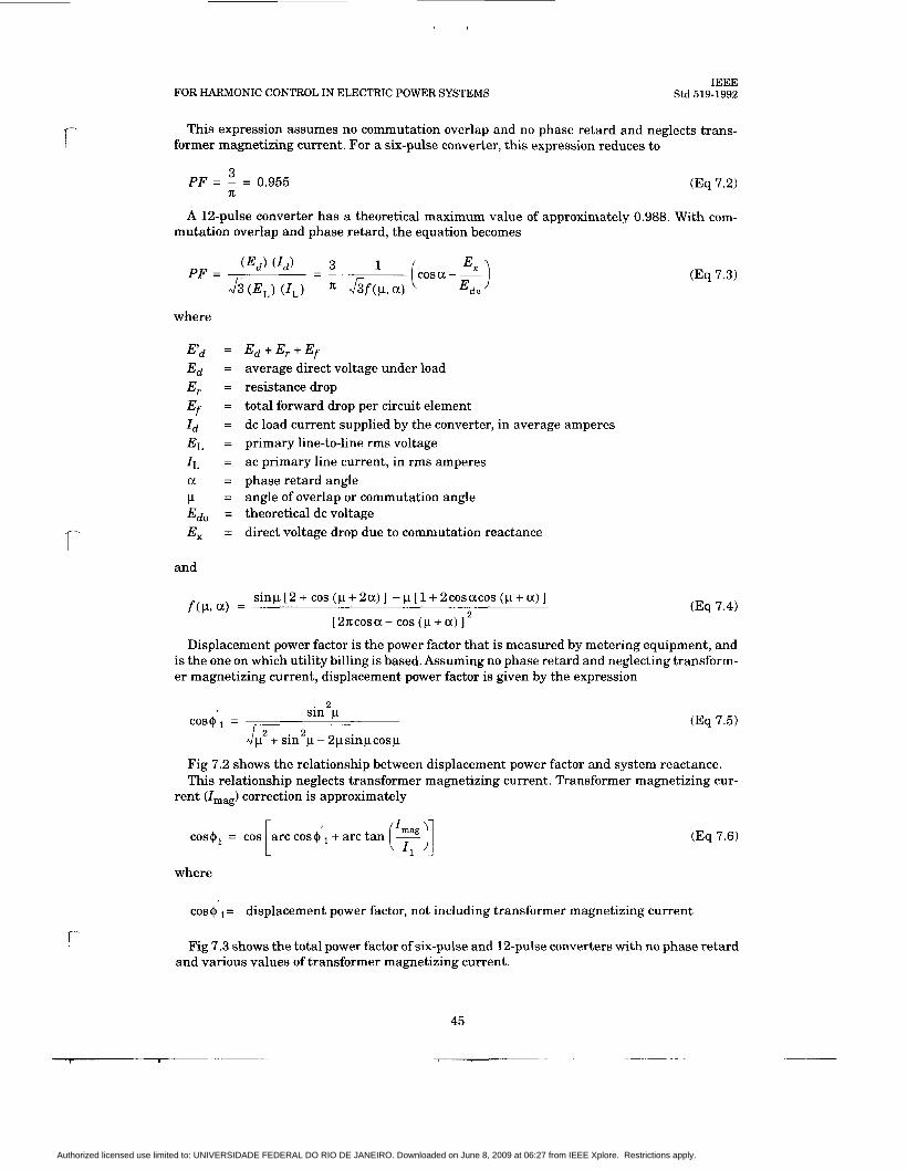
r
l-
FOR HARMONIC CONTROL IN ELECTRIC POWER SYSTEMS IEEE
Std 519-1992
This expression assumes no commutation overlap and no phase retard and neglects trans- former magnetizing current. For a six-pulse converter, this expression reduces to
3 PF = - = 0.955 (Eq 7.2) n A 1Zpulse converter has a theoretical maximum value of approximately 0.988. With com-
mutation overlap and phase retard, the equation becomes
Ed + E , + Ef average direct voltage under load resistance drop total forward drop per circuit element dc load current supplied by the converter, in average amperes primary line-to-line rms voltage ac primary line current, in rms amperes phase retard angle angle of overlap or commutation angle theoretical dc voltage direct voltage drop due to commutation reactance
s inp[2+ c o s ( p + 2 a ) ] -p[1+2cosacos ( p + a ) ]
[2x:cosa- cos ( p + a ) ] f ( p 9 a) = 2
(Eq 7.3)
(Eq 7.4)
Displacement power factor is the power factor that is measured by metering equipment, and is the one on which utility billing is based, Assuming no phase retard and neglecting transform- er magnetizing current, displacement power factor is given by the expression
2 sin p cos+, = (Eq 7.5)
2 2 p +sin p- 2psinpcosp
Fig 7.2 shows the relationship between displacement power factor and system reactance. This relationship neglects transformer magnetizing current. Transformer magnetizing cur-
rent (Imag) correction is approximately
a rccos+,+arc tan
where
(Eq 7.6)
cos+ , = displacement power factor, not including transformer magnetizing current
r Fig 7.3 shows the total power factor of six-pulse and 12-pulse converters with no phase retard and various values of transformer magnetizing current.
45
Authorized licensed use limited to: UNIVERSIDADE FEDERAL DO RIO DE JANEIRO. Downloaded on June 8, 2009 at 06:27 from IEEE Xplore. Restrictions apply.

IEEE Std 519-1992 IEEE RECOMMENDED PRACTICES AND REQUIREMENTS
PERCEhT VOL'I ZGE. 1 0 0
0 96
0 92
0 88
0 84
5 0 8 0 - 0 76
0 72
0 64
0 61
1 1 1 1 1 1 1 1 1 1 1 1 1 1 1 1 1
Fig 7.2 Determination of Displacement Power Factor
(Neglecting Transformer Exciting Current)
Line-commutated static power converters need a supply of reactive power whether they are rectifying or inverting. In either case, the thyristor can only turn the current on after the volt- age has become more positive than the previous phase voltage. The closer the operation is to zero volts dc (see Fig 7.41, the more reactive power is required with the same output current. The reactive power requirement of commonly used converter circuits is a function of load and output voltage and may be calculated.
It is possible to reduce reactive power requirements of line-commutated static power convert- ers by
(1) Limiting the amount of phase control required during normal operation (limit a) (2) Lower reactance of converter transformers (limit p) (3) Asymmetrical or sequential control of converters (limit a)
7.1.1 Limiting Phase Control. Static power converters usually are designed to operate from a power system whose voltage range is from +lo% to -5% of nominal voltage. If the con- verter is to invert, it usually is designed to operate with a f10% voltage. This means that the power system voltage can vary over f10% and still have satisfactory operation of the con- verter. If some other means of voltage control is used to maintain the power system voltage in a narrower range, the secondary voltage of the converter transformer can be chosen so that, during normal operation, the converter is operated more nearly fully phased on (less retard).
If the load that the converter is feeding requires a wide range of voltage, voltage control from transformer taps can be used to limit the amount of phase control used by the converter.
46
Authorized licensed use limited to: UNIVERSIDADE FEDERAL DO RIO DE JANEIRO. Downloaded on June 8, 2009 at 06:27 from IEEE Xplore. Restrictions apply.
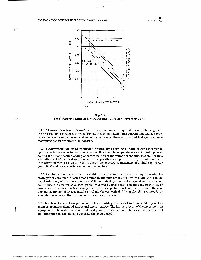
r
f
FOR HARMONIC CONTROL IN ELECTRIC POWER SYSTEMS - 0.98
0.96
0.94
0.92
0.90
0.88
0.86
I I I I I
0 5 10
Ex (76) REACTANCE FACTOR - Edo
IEEE Std 519-1992
Fig 7.3 Total Power Factor of Six-Pulse and 12-Pulse Converters, a = 0
7.1.2 Lower Reactance Transformer. Reactive power is required to excite the magnetiz- ing and leakage reactances of transformers. Reducing magnetizing current and leakage reac- tance reduces reactive power and commutation angle. However, reduced leakage reactance may introduce circuit protection hazards.
7.1.3 Asymmetrical or Sequential Control. By designing a static power converter to operate with two converter sections in series, it is possible to operate one section fully phased on and the second section adding or subtracting from the voltage of the first section. Because a smaller part of the total static converter is operating with phase control, a smaller amount of reactive power is required. Fig 7.4 shows the reactive requirement of a single converter (solid line) and two converters in series (dashed line).
7.1.4 Other Considerations. The ability to reduce the reactive power requirements of a static power converter is sometimes limited by the number of units involved and the econom- ics of using any of the above methods. Voltage control by means of a regulating transformer can reduce the amount of voltage control required by phase retard in the converter. A lower reactance converter transformer may result in unacceptable short-circuit currents in the con- verter. Asymmetrical or sequential control may be economical if the application requires large enough converters so that two converter sections are needed.
7.2 Reactive Power Compensation. Electric utility rate structures are made up of two main components: demand charge and energy charge. The first is a result of the investment in equipment to furnish that amount of total power to the customer. The second is the result of fuel that must be expended to generate the energy used.
47
Authorized licensed use limited to: UNIVERSIDADE FEDERAL DO RIO DE JANEIRO. Downloaded on June 8, 2009 at 06:27 from IEEE Xplore. Restrictions apply.

IEEE Std 519-1992 IEEE RECOMMENDED PRACTICES AND REQUIREMENTS
Fig 7.4 Reactive Power vs. DC Volts of Converter
The total load (kVA) is made up of two components in quadrature: active power (kW) and re- active power (kvar), see Fig 7.5. If the kVA can be reduced by furnishing reactive power locally, the demand charge can be minimized.
Fig 7.5 Relationship Between kW and kvar
Reactive power sources are
(1) Static power capacitors (2) Synchronous machines (3) Forced-commutated static power converters
7.2.1 Reactive Power Compensation Using Static Power Capacitors. Power capaci- tors are an inexpensive source of reactive power. They provide vars that are proportional to the square of the applied voltage. These vars cause a voltage rise through the inductive reac- tance of the power system, which raises the operating voltage level. Capacitors must be switched in order to control voltages and provide variable reactive power.
Four methods of controlling vars using capacitors, in the order of complexity, are
(1) Switching by power circuit breakers, circuit switchers, or vacuum switches (2) Back-to-back phase control thyristor switching of a reactor in parallel with the capaci-
tor bank (3) Back-to-back thyristor switching of capacitors that will turn on or off at current zero (4) Saturable reactor in parallel with capacitor bank
48
Authorized licensed use limited to: UNIVERSIDADE FEDERAL DO RIO DE JANEIRO. Downloaded on June 8, 2009 at 06:27 from IEEE Xplore. Restrictions apply.

FOR HARMONIC CONTROL IN ELECTRIC POWER SYSTEMS IEEE
Std 519-1992
7.2.1.1 Switching Power Capacitors by Circuit Breakers, Circuit Switchers, or Vacuum Switches. For controlling reactive power on a continuous basis, switching power capacitors by circuit breakers, circuit switchers, or vacuum switches requires a switching device that can be operated frequently and can interrupt a t current zero with a high voltage across the contacts without reignition. Because of these requirements, this method is used only for switching larger banks once or twice a day, when the demand changes from normal to light load conditions. The switching device has the special requirement of being able to inter- rupt a current that leads the voltage by 90". Where these limitations are not an operating dis- advantage, this method of controlling vars is most economical. See Fig 7.6.
T T T T 1 2 4 8 TO PLANT LOADS
Fig 7.6 Capacitors Switched in Binary Values
f-
7.2.1.2 Back-to-Back Phase Control of a Thyristor-Controlled Reactor (Inductor) (TCR). Back-to-back phase control of a thyristor-controlled reactor in parallel with capacitors has the advantage of smooth var control over the operating range of the equipment. By switching the current to the reactor, the problems related to capacitor switching are avoided. Thyristor controlling of a balanced three-phase load causes fifth, seventh, etc., harmonic cur- rents. Therefore, the capacitors may be divided into two or more sections with tuning reactors to filter these harmonics. The reactor var rating is normally equal to the capacitor rating to obtain full control. More capacitors can be supplied if a bias of vars is needed on the system. See Fig 7.7.
7.2.1.3 Back-to-Back Thyristor Switching of Capacitors (TSC) at Current Zero. Back-to-back thyristor switching of capacitors at zero current leaves the capacitor charged with either a positive or a negative full charge on the capacitor. The thyristor's fine control allows the switching on of the capacitor when the system voltage equals the charged capacitor voltage. This eliminates any transients on the system. The capacitors are switched in finite steps as reactive power is needed. The switched capacitors can be tuned with a reactor to filter harmonics on the system. This system can also be used with a fixed bias of capacitors to pro- vide base vars with the switched capacitors to be used for variable vars. A combination of thy- ristor-switched capacitors and a thyristor-controlled reactor can be used to get vernier control between the steps of the TSC. See Fig 7.8.
7.2.1.4 Saturable Reactor in Parallel With a Capacitor Bank. A saturable reactor in parallel with a capacitor bank provides a variable var supply that requires no external control circuitry. This system consists of a self-saturating reactor in parallel with a capacitor bank that can be arranged into tuned series circuits. The self-saturating reactor draws heavy cur- rents a t overvoltages so that the voltage drop through the system reactance counteracts the
49
Authorized licensed use limited to: UNIVERSIDADE FEDERAL DO RIO DE JANEIRO. Downloaded on June 8, 2009 at 06:27 from IEEE Xplore. Restrictions apply.
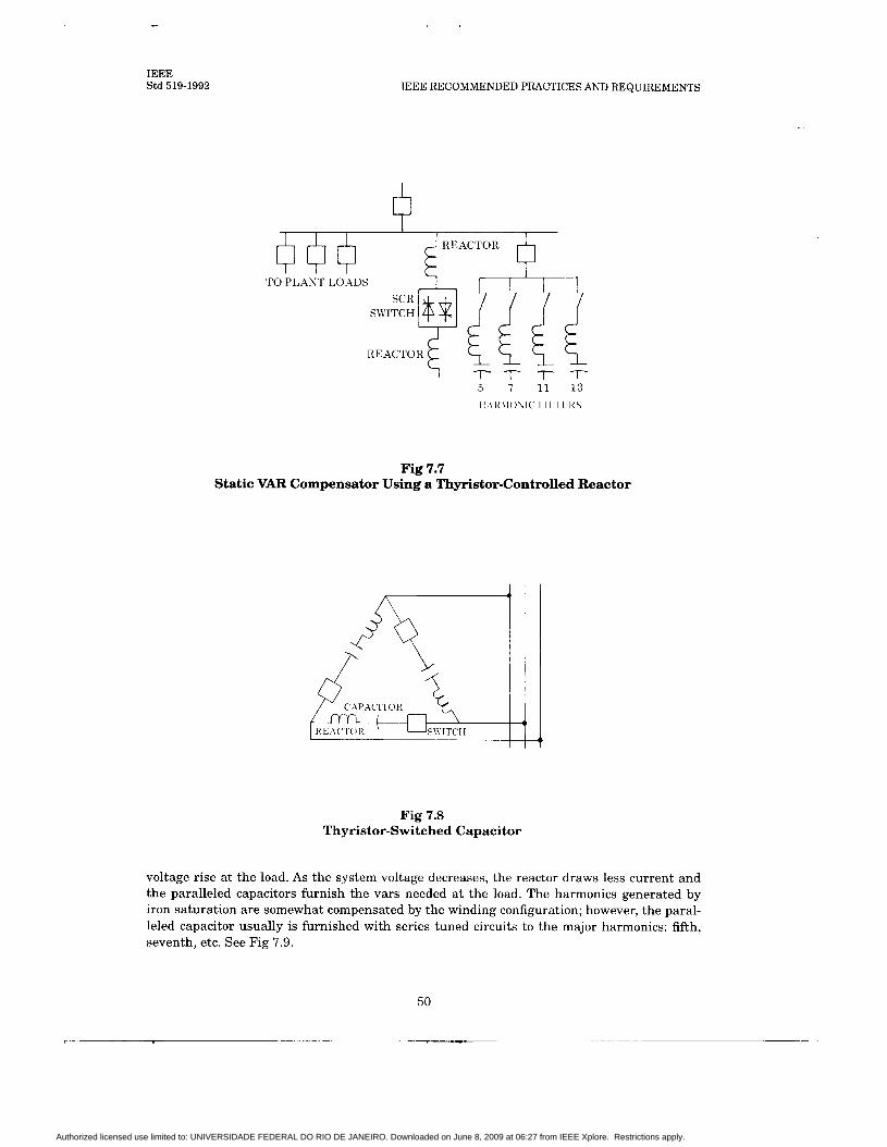
IEEE Std 519-1992 IEEE RECOMMENDED PRACTICES AND REQUIREMENTS
TO PLANT LO.-\DS cl cl + K A C T A
TO PLANT LO.-\DS
T T T T 5 7 11 13
c: T 11
T 13
Fig 7.7 Static VAR Compensator Using a Thyristor-Controlled Reactor
Fig 7.8 Thyristor-Switched Capacitor
voltage rise a t the load. As the system voltage decreases, the reactor draws less current and the paralleled capacitors furnish the vars needed a t the load. The harmonics generated by iron saturation are somewhat compensated by the winding configuration; however, the paral- leled capacitor usually is furnished with series tuned circuits to the major harmonics: fifth, seventh, etc. See Fig 7.9.
50
Authorized licensed use limited to: UNIVERSIDADE FEDERAL DO RIO DE JANEIRO. Downloaded on June 8, 2009 at 06:27 from IEEE Xplore. Restrictions apply.

FOR HARMONIC CONTROL IN ELECTRIC POWER SYSTEMS IEEE
Std 519-1992
r
r-
' REACTOR 7 f 7 5 t h 7th 11 th 13th
l l l l < \ l ~ ~ \ l ~ I I I 1 1 I<\
Fig 7.9 Reactive Power Compensation Using Saturable Reactor
7.2.2 Reactive Power Compensation Using Rotating Machinery. Synchronous machines can be made to operate with either a leading or lagging power factor by controlling the field excitation. This property can be used to provide reactive power compensation on a dynamic basis with the appropriate control strategy.
A synchronous machine is referred to as a synchronous condenser when it is dedicated solely to reactive power compensation. It has no mechanical load, and all machine capacity is avail- able as reactive power. A synchronous condenser often is used with a fixed capacitor bank equal to the machine vars. This will allow a total range of operation from zero to twice the machine rating for vars with proper adjustment of the field excitation.
A synchronous motor can be sized to provide vars. When the system includes synchronous motors, consideration should be given to this possibility because the incremental cost of pro- viding leading vars can be quite attractive. Furthermore, with proper control strategy, the vars can be adjusted to the system requirements (power factor regulator).
When synchronous machines are used to provide power factor compensation, the following technical areas of interest should be considered:
Time profile of the var and kW demand on the bus to be protected Allowable voltage deviation on this bus (transient and steady state) Time profile of the vars the synchronous machine must provide in order to maintain the voltage deviations limits
NOTE: The synchronous machine, by virtue of its stored magnetic energy, will be able to provide instanta- neous compensation of a voltage disturbance. The field must be adjusted to provide complete compensation. The time required can be reduced by field forcing with a static power converter field exciter.
Compatibility with static power converters in such areas as
(a) Voltage imbalance sensitivity (b) AC line harmonic heating (c) Bearing currents
Control limits that will avoid
(a) Exceeding machine pullout torque capability (b) Exceeding machine thermal limit
7.2.3 Reactive Power Compensation Using Self-Commutated Converters. The tech- nique of forcing commutation to a different phase before the voltage has become more positive produces leading vars. An example of this type of converter is an inverter using a fuel cell or battery as an energy source.
Self-commutated converters incorporate their own means of commutation and can commu- tate independently of the line voltage. These systems are voltage sources rather than current
51
Authorized licensed use limited to: UNIVERSIDADE FEDERAL DO RIO DE JANEIRO. Downloaded on June 8, 2009 at 06:27 from IEEE Xplore. Restrictions apply.
IEEE Std 519-1992 IEEE RECOMMENDED PRACTICES AND REQUIREMENTS
sources, as in line-commutated conversion. The self-commutated converter functions nearly the same as a conventional utility generator; that is, a voltage source behind an impedance. The converters have essentially no inductance on the dc side, but do require additional induc- tance on the ac side. Reactive compensation is not required.
Harmonic voltage generation can be controlled by the use of a number of different cancella- tion techniques, such as pulse multiplication and step wave, that cancel the lower order har- monic pairs. Treatment of the remaining harmonics is quite different with the forced commutated converter. The inductance on the ac side of forced commutated converters offers a high impedance to the passage of the higher harmonic currents. In cases in which the ac system is stiff relative to the ac side reactance, no control of harmonic voltages at the ac bus is re- quired. A small, high-pass shunt filter or a small capacitor bank suffices with 18-pulse or 24- pulse configurations because the ac side inductance restricts harmonic current flow.
7.3 Control of Harmonic Currents. The diagram of Fig 7.10 shows a converter supplied from power source, G, over a three-phase line, L1. The reactance of the source, X, + x T 2 , and the line, L1, are in series with the converter transformer reactance, Xt. If a harmonic current, Ih, flows between the converter and the source, there will be harmonic voltage E h = I h xh at location A. ( x h is the reactance of the source a t the harmonic frequency, h.) When there is an extension, L,, for supplying other loads, the harmonic voltage at A will cause a harmonic cur- rent to flow over that line as well, although the power to the rectifier is supplied only over line L l . The higher the value of X,, the greater will be the harmonic voltage a t A and the higher the magnitude of the harmonic currents flowing over line L2. Actually, the harmonic currents from a converter can flow into any part of an ac system to which it is connected, as determined by the impedances of the various branches of the system a t the harmonic frequencies. The harmonic voltages and currents can be calculated.
Harmonic current can be controlled by several techniques. These include
(1) Shunt filters (2) Phase multiplication (3) Harmonic compensation or injection
7.3.1 Shunt Filters. Shunt filters for reduction of harmonic currents flowing into an ac power system consist of one or more tuned circuits consisting of series L-C circuits. The filter commonly used on HVDC transmission consists of individual circuits tuned for the 5th, 7th, llth, and 13th harmonics plus a high-pass filter tuned near the 17th harmonic. Filters in industrial systems can be simpler because the filter size compared to the system capacity is large. Filters are usually sized to provide vars for power factor improvement as well as for fil- tering the harmonic currents. As a result, the size of the filter is large enough to control the flow of not only the harmonic to which it is tuned, but also the higher order harmonics. The impedance of the filter with respect to the power system is low. In low-voltage systems, the XIR ratio is small; therefore, a single filter suffices because of the additional damping. The damping factor is greater with a small XIR ratio.
7.3.1.1 Shunt Filter Design. Shunt filters are made up of two components, the capacitor and the inductor. The capacitor must be capable of withstanding the arithmetic sum of the peak voltage of the fundamental and harmonic voltage drop across the capacitor. The current as seen by the filter is the voltage impressed on the filter divided by the total reactance of the tuning inductor and the capacitor. Since the total reactance is less than the capacitive reac- tance (the inductive reactance has an opposite sign to the capacitive reactance so that the total is the difference of the two values), the fundamental current into the filter will be larger than into the capacitor without the tuning reactor. The harmonic voltage across the capacitor is the voltage, due to the harmonic current, to which the filter is tuned that is available from the system times the reactance of the capacitor a t the tuned frequency.
52
Authorized licensed use limited to: UNIVERSIDADE FEDERAL DO RIO DE JANEIRO. Downloaded on June 8, 2009 at 06:27 from IEEE Xplore. Restrictions apply.
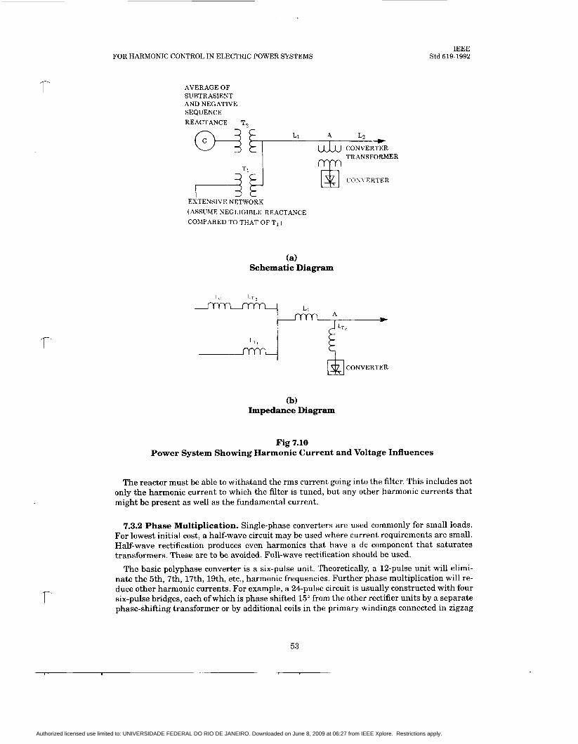
FOR HARMONIC CONTROL IN ELECTRIC POWER SYSTEMS IEEE
Std 519-1992
AVERAGE OF SUBTRASIENT AND NEGATIVE SEQUENCE REACTANCE
TRANSFORMER rvyn
EXTENSIVE NETWORK (ASSUME NEGLIGIBLE REACTANCE COMPARED TO THAT OF Ti )
COSVERTER El
(a) Schematic Diagram
I !-
CONVERTER 2
(b) Impedance Diagram
Fig 7.10 Power System Showing Harmonic Current and Voltage Influences
The reactor must be able to withstand the rms current going into the filter. This includes not only the harmonic current to which the filter is tuned, but any other harmonic currents that might be present as well as the fundamental current.
7.3.2 Phase Multiplication. Single-phase converters are used commonly for small loads. For lowest initial cost, a half-wave circuit may be used where current requirements are small. Half-wave rectification produces even harmonics that have a dc component that saturates transformers. These are to be avoided. Full-wave rectification should be used.
The basic polyphase converter is a six-pulse unit. Theoretically, a 12-pulse unit will elimi- nate the 5th, 7th, 17th, 19th, etc., harmonic frequencies. Further phase multiplication will re- duce other harmonic currents. For example, a 24-pulse circuit is usually constructed with four six-pulse bridges, each of which is phase shifted 15" from the other rectifier units by a separate phase-shifting transformer or by additional coils in the primary windings connected in zigzag
53
Authorized licensed use limited to: UNIVERSIDADE FEDERAL DO RIO DE JANEIRO. Downloaded on June 8, 2009 at 06:27 from IEEE Xplore. Restrictions apply.

IEEE Std 519-1992 IEEE RECOMMENDED PRACTICES AND REQUIREMENTS
or hexagon, see Fig 7.11. If one six-pulse unit is out of service, the harmonic current equivalent to that unit will be present. Large installations may require the addition of shunt filters to min- imize harmonic currents. Phase multiplication is most effective for an installation in which equal size converters with equal loading and phase retard are used.
UTILITY SUPPLY
Fig 7.11 Transformer Connections for a 24-Pulse System
7.3.3 Harmonic Injection. Harmonic currents can be eliminated by inducing harmonic fluxes in the core of a transformer with a 180" phase shift from the harmonic fluxes induced by the current flowing in the transformer secondary.
Adaptive compensators are still in the experimental stage. These devices are designed to constantly monitor the load current and inject a current equal and opposite to the distortion component and, thus, cancel it.
54
Authorized licensed use limited to: UNIVERSIDADE FEDERAL DO RIO DE JANEIRO. Downloaded on June 8, 2009 at 06:27 from IEEE Xplore. Restrictions apply.
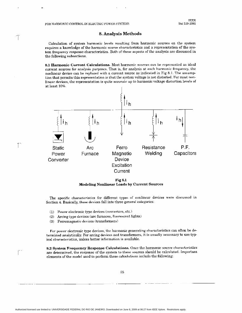
FOR HARMONIC CONTROL IN ELECTRIC POWER SYSTEMS
8. Analysis Methods
IEEE Std 519-1992
Calculation of system harmonic levels resulting from harmonic sources on the system requires a knowledge of the harmonic source characteristics and a representation of the sys- tem frequency response characteristics. Both of these aspects of the analysis are discussed in the following subsections.
8.1 Harmonic Current Calculations. Most harmonic sources can be represented as ideal current sources for analysis purposes. That is, for analysis a t each harmonic frequency, the nonlinear device can be replaced with a current source as indicated in Fig 8.1. The assump- tion that permits this representation is that the system voltage is not distorted. For most non- linear devices, the representation is quite accurate up to harmonic voltage distortion levels of a t least 10%.
I
Static Arc Ferro Resistance P.F. Power Furnace Magnet i o Welding Capacitors
Converter Device Excitation Current
Fig 8.1 Modeling Nonlinear Loads by Current Sources
The specific characteristics for different types of nonlinear devices were discussed in Section 4. Basically, these devices fall into three general categories:
(1) Power electronic type devices (converters, etc.) (2) Arcing type devices (arc furnaces, fluorescent lights) (3) Ferromagnetic devices (transformers)
For power electronic type devices, the harmonic generating characteristics can often be de- termined analytically. For arcing devices and transformers, it is usually necessary to use typ- ical characteristics, unless better information is available.
8.2 System Frequency Response Calculations. Once the harmonic source characteristics are determined, the response of the system to these sources should be calculated. Important elements of the model used to perform these calculations include the following:
55
Authorized licensed use limited to: UNIVERSIDADE FEDERAL DO RIO DE JANEIRO. Downloaded on June 8, 2009 at 06:27 from IEEE Xplore. Restrictions apply.
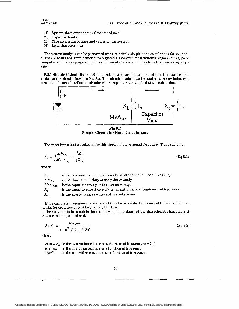
IEEE Std 519-1992 IEEE RECOMMENDED PRACTICES AND REQUIREMENTS
(1) System short-circuit equivalent impedance (2) Capacitor banks (3) Characteristics of lines and cables on the system (4) Load characteristics
The system analysis can be performed using relatively simple hand calculations for some in- dustrial circuits and simple distribution systems. However, most systems require some type of computer simulation program that can represent the system at multiple frequencies for anal- ysis.
8.2.1 Simple Calculations. Manual calculations are limited to problems that can be sim- plified to the circuit shown in Fig 8.2. This circuit is adequate for analyzing many industrial circuits and some distribution circuits where capacitors are applied at the substation.
Fig 8.2 Simple Circuit for Hand Calculations
The most important calculation for this circuit is the resonant frequency. This is given by
(Eq 8.1)
where
hr W A S , Mumcap xc x s c
is the resonant frequency as a multiple of the fundamental frequency is the short-circuit duty at the point of study is the capacitor rating at the system voltage is the capacitive reactance of the capacitor bank at fundamental frequency is the short-circuit reactance a t the substation
If the calculated resonance is near one of the characteristic harmonics of the source, the po-
The next step is to calculate the actual system impedance at the characteristic harmonics of tential for problems should be evaluated further.
the source being considered:
(Eq 8.2) R + j o L
1 - o2 ( L C ) + j w R C Z ( 0 ) =
where
Z(w) = Z h is the system impedance as a function of frequency R + joL is the source impedance as a function of frequency VjoC is the capacitive reactance as a function of frequency
= 27cf
56
Authorized licensed use limited to: UNIVERSIDADE FEDERAL DO RIO DE JANEIRO. Downloaded on June 8, 2009 at 06:27 from IEEE Xplore. Restrictions apply.

FOR HARMONIC CONTROL IN ELECTRIC POWER SYSTEMS IEEE
Std 519-1992
r
r
T
Once 2, is obtained at each characteristic harmonic, the voltage magnitude can be calculated at each harmonic as follows:
(Eq 8.3)
where
I , = the source current a t each characteristic harmonic
Further calculations can be performed using the individual harmonic voltages and currents. It may be important to calculate quantities such as the total harmonic distortion (THD) and the I-T product for telephone interference.
8.2.2 Computer Simulations. When the system being studied is more complicated than the circuit in Fig 8.2, computer simulations are usually required. With a computer program, one can perform analyses including
(1) Frequency scans for system response (2) Response to multiple harmonic sources (3) Multiphase, unbalanced system solutions
The most common method employed in a computer program for harmonic analysis is a direct solution of the admittance matrix a t multiple frequencies. With this type of solution, nonlinear devices are modeled as ideal voltage sources or current sources a t the harmonic frequencies. Frequency dependence of system elements (transmission lines, transformers, motors, etc.) should be included in the calculation even though the system is assumed to be linear at each individual frequency. For most systems, the admittance matrix is sparse, thus allowing for ef- ficiencies in solution speed and memory utilization.
Another approach that has been used for harmonic simulations has been termed a harmonic load flow. A load flow equation formulation is used as opposed to the direct solution of the ad- mittance matrix. That is, the power constraints a t the load and source nodes are included. A Newton-Raphson iterative method is used for solution. Implementations of this approach have been for balanced systems only, and it is generally more applicable to transmission system analysis than to distribution systems.
8.3 Modeling Guidelines for Harmonic Analysis. As mentioned previously, general mod- eling guidelines for harmonic analysis are difficult to develop because of the number of parameters that can affect system ffequency response characteristics. However, it is worth- while to identify the most important system characteristics that affect the frequency response.
8.3.1 Overall Modeling Complexity. For industrial and distribution systems, it is gener- ally sufficient to model the system in detail only on the low side of the step-down transformer from the transmission system. A short-circuit equivalent at the high side of the step-down transformer is sufficient because the impedance is usually dominated by the step-down trans- former itself. On the low side of the step-down transformer, it is important to include nodes (buses) at all capacitor locations and large loads. It is usually acceptable to ignore the capaci- tance of lines because capacitor banks dominate a t these lower voltages. However, the capaci- tance of any significant insulated cable lengths can be important. When calculating the I.T product at the higher frequencies (above the 25th harmonic), the capacitance of distribution lines is important.
The existence of a capacitor bank near the primary of the step-down transformer must be modeled because the combination of the reactance of the step-down transformer in series with the capacitor bank is a “filter” when viewed from the harmonic source on the secondary side of the transformer.
57
7- I
Authorized licensed use limited to: UNIVERSIDADE FEDERAL DO RIO DE JANEIRO. Downloaded on June 8, 2009 at 06:27 from IEEE Xplore. Restrictions apply.
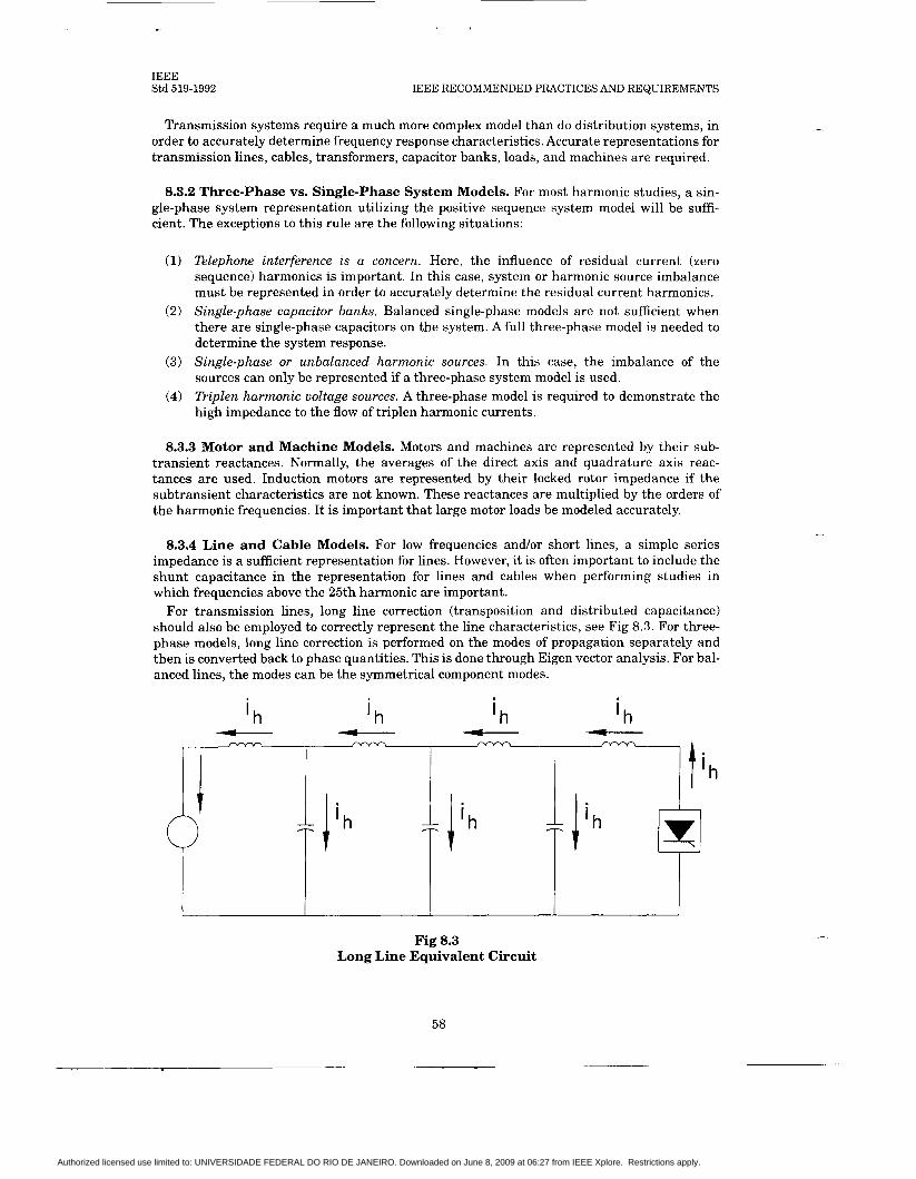
IEEE Std 519-1992 IEEE RECOMMENDED PRACTICES AND REQUIREMENTS
Transmission systems require a much more complex model than do distribution systems, in order to accurately determine frequency response characteristics. Accurate representations for transmission lines, cables, transformers, capacitor banks, loads, and machines are required.
8.3.2 Three-phase vs. Single-phase System Models. For most harmonic studies, a sin- gle-phase system representation utilizing the positive sequence system model will be suffi- cient. The exceptions to this rule are the following situations:
(1) Telephone interference is a concern. Here, the influence of residual current (zero sequence) harmonics is important. In this case, system or harmonic source imbalance must be represented in order to accurately determine the residual current harmonics.
(2) Single-phase capacitor banks. Balanced single-phase models are not sufficient when there are single-phase capacitors on the system. A full three-phase model is needed to determine the system response.
(3) Single-phase or unbalanced harmonic sources. In this case, the imbalance of the sources can only be represented if a three-phase system model is used.
(4) l l iplen harmonic voltage sources. A three-phase model is required to demonstrate the high impedance to the flow of triplen harmonic currents.
8.3.3 Motor and Machine Models. Motors and machines are represented by their sub- transient reactances. Normally, the averages of the direct axis and quadrature axis reac- tances are used. Induction motors are represented by their locked rotor impedance if the subtransient characteristics are not known. These reactances are multiplied by the orders of the harmonic frequencies. I t is important that large motor loads be modeled accurately.
8.3.4 Line and Cable Models. For low frequencies and/or short lines, a simple series impedance is a sufficient representation for lines. However, it is often important to include the shunt capacitance in the representation for lines and cables when performing studies in which frequencies above the 25th harmonic are important.
For transmission lines, long line correction (transposition and distributed capacitance) should also be employed to correctly represent the line characteristics, see Fig 8.3. For three- phase models, long line correction is performed on the modes of propagation separately and then is converted back to phase quantities. This is done through Eigen vector analysis. For bal- anced lines, the modes can be the symmetrical component modes.
' h ' h l h
Fig 8.3 Long Line Equivalent Circuit
58
Authorized licensed use limited to: UNIVERSIDADE FEDERAL DO RIO DE JANEIRO. Downloaded on June 8, 2009 at 06:27 from IEEE Xplore. Restrictions apply.

FOR HARMONIC CONTROL IN ELECTRIC POWER SYSTEMS IEEE
Std 519-1992
r
8.3.5 Transformer Models. The transformer has two components that are of concern:
(1) Leakage impedance (2) Magnetizing impedance
A lumped impedance model generally is adequate for the leakage impedance. However, it is important to remember that the resistive component of this impedance is not constant with fre- quency. A conservative assumption used for harmonic studies of industrial distribution sys- tems is that the transformer X R ratio is constant with frequency and is equal to ten. For transmission power transformers, the X R ratio typically is in the range of 20 to 30. For distri- bution transformers, a range of 5 to 10 is more typical.
If the transformer is not a significant source of harmonics, the magnetizing impedance can be neglected. If the harmonic production of the transformer is significant, the magnetizing branch can be modeled as a current source of harmonics.
For three-phase transformers, the winding connections are important in determining the ef- fect of the transformer on zero-sequence harmonic components. Delta connections isolate these currents from one voltage level to the next.
8.3.6 Load Models. The important components of the load for harmonic studies are described in 5.3. They are
(1) The step-down transformer (2) The resistive component (3) The motor components
The step-down transformer becomes important at higher frequencies because it is a reac- tance in series with the load. The resistive component provides damping when the overall sys- tem response is near a parallel resonance (high impedance). The motor components are important because they can shift the system resonance slightly as they are a source whose re- actance is in parallel with the system reactance.
In general, system loads have only a minimal effect on overall system response characteris- tics unless the system is near a resonant frequency. When close to resonance, the effect of the load is to reduce the peak resonant impedance (damping) or to shift the resonant frequency (motor inductance).
8.4 Telephone Interference. Two equations generally are used in North America.
8.4.1 Voltage Telephone Influence Factor. The voltage telephone interference factor, VTIF , is
where
(Eq 8.4)
V1 = fundamental line-to-neutral voltage (rms) Ih = harmonic current into power system Zh = power system impedance a t harmonic order h
Th H = upper limit of harmonics, 5000 Hz
= telephone interference weighting factor (TIF) (1960 curves currently in use)
59
Authorized licensed use limited to: UNIVERSIDADE FEDERAL DO RIO DE JANEIRO. Downloaded on June 8, 2009 at 06:27 from IEEE Xplore. Restrictions apply.

IEEE Std 519-1992 IEEE RECOMMENDED PRACTICES AND REQUIREMENTS
8.4.2 I-T Product. The other equation that is frequently used is the I.T product:
H 2 I . T = C (IhTh)
J h = l (Eq 8.5)
8.5 Line Notching Calculations (for Low-Voltage Systems). Fig 8.4 shows a typical three-phase full-control converter bridge. The thyristors operate in pairs to convert three phase ac to dc by switching the load among the various thyristor pairs six times per cycle. During the process, a brief short circuit produces a notch in the line-to-line voltage waveform.
SOURCE
REACTANCE FIRING ORDER:
3 PHASE FULL WAVE RECTIFIER
I I I I
Fig 8.4 Three-phase Full Wave Converter
The current in the converter of Fig 8.4 has been flowing from Phase A through thyristor 1. When thyristor 3 fires [see Figs 8.5(a), 8.5(b), and 8.5(c)l a t time, t (30" on the line-to-line volt- age base), the current begins to transfer from Phase A to Phase B. Source reactance prevents instantaneous transfer, thus the commutating time (angle) required becomes the notch width, p.
The resulting notch is shown on a line-to-neutral basis in Fig 8.5(a) and on a line-to-line basis in Fig 8.5(b). The latter clearly illustrates the shorting action when both thyristors 1 and 3 are conducting simultaneously. The other notches reflect the action of the thyristor on the other phases of the ac circuitry.
8.5.1 Notch Area Calculations. The area of the notch is dependent upon the volt-seconds absorbed in the circuits from the source to the point of the circuit that is of interest. The area of the notch is an indication of the effect that the static power converter will have on other loads.
60
Authorized licensed use limited to: UNIVERSIDADE FEDERAL DO RIO DE JANEIRO. Downloaded on June 8, 2009 at 06:27 from IEEE Xplore. Restrictions apply.

FOR HARMONIC CONTROL IN ELECTRIC POWER SYSTEMS IEEE
Std 519-1992
LINE NEUTRAL VOLTAGE
C A B C A B
NOTE: The two other phases are similar to A-B. The width of the notches is exaggerated and ringing is omitted for clarity.
Fig 8.5 Voltage Notches
The notch area is calculated (refer to Fig 8.6) as follows:
LLe v - - L , +L,+Ls
f
A, = VNtN
(Eq 8.6)
(Eq 8.7)
(Eq 8.7)
Authorized licensed use limited to: UNIVERSIDADE FEDERAL DO RIO DE JANEIRO. Downloaded on June 8, 2009 at 06:27 from IEEE Xplore. Restrictions apply.
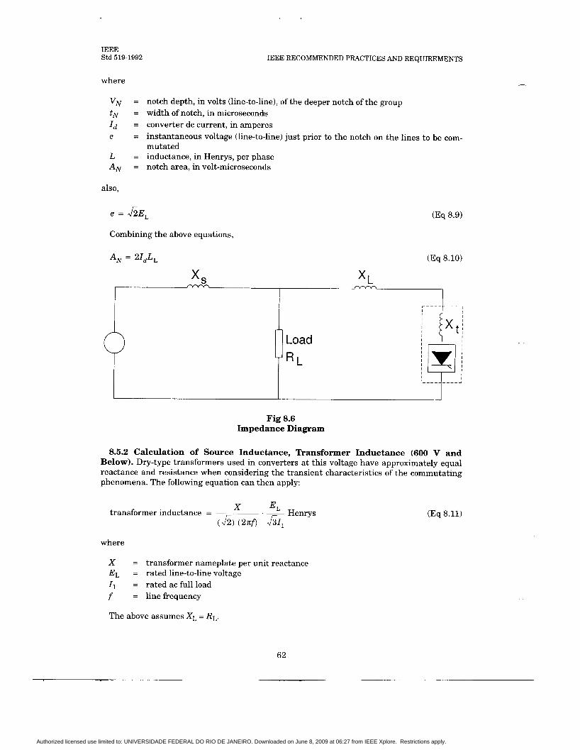
IEEE Std 519-1992
where
IEEE RECOMMENDED PRACTICES AND REQUIREMENTS
VN tN = width of notch, in microseconds Id = converter dc current, in amperes e
L = inductance, in Henrys, per phase AN = notch area, in volt-microseconds
= notch depth, in volts (line-to-line), of the deeper notch of the group
= instantaneous voltage (line-to-line) just prior to the notch on the lines to be com- mutated
also,
e = J ~ E ~ (Eq 8.9)
Combining the above equations,
A, = 21dL, (Eq 8.10)
I 5
Load
R L
Fig 8.6 Impedance Diagram
8.5.2 Calculation of Source Inductance, Transformer Inductance (600 V and Below). Dry-type transformers used in converters a t this voltage have approximately equal reactance and resistance when considering the transient characteristics of the commutating phenomena. The following equation can then apply:
Henrys E , .~ X transformer inductance = (h) (27cf) &Il
where
X = transformer nameplate per unit reactance EL = rated line-to-line voltage 11 = rated ac full load f = linefrequency
The above assumes X , = R L .
(Eq 8.11)
62
Authorized licensed use limited to: UNIVERSIDADE FEDERAL DO RIO DE JANEIRO. Downloaded on June 8, 2009 at 06:27 from IEEE Xplore. Restrictions apply.

FOR HARMONIC CONTROL IN ELECTRIC POWER SYSTEMS IEEE
Std 519-1992
c
f
8.5.3 Calculation of Line Inductance. Typically, the per-phase line inductance on a three-phase ac line can be considered to be 0.3 yH per foot of line, or about 1 pWm.
8.6 Total Harmonic Distortion. The total harmonic distortion (THD) is used to define the effect of harmonics on the power system voltage. It is used in low-voltage, medium-voltage, and high-voltage systems. It is expressed as a percent of the fundamental and is defined as
squares of amplitude of all harmonic voltages ’ 100% (Eq 8.12)
square of the amplitude of the fundamental voltage THD =
(Eq 8.13) 1; ’h
THD = h=2. 100% VI
(See Section 4 for specific harmonics generated by different loads.)
8.6.1 Relationship Between Line Notching and Total Harmonic Distortion. See Figs
From the above, for f 1 = 60 Hz and EL = 460 V, 8.5 and 8.7.
Vh = I m
2
12. <tN + 4* (2) t,
1 i f , * The “2” refers to the two deep notches and the “4” refers to the four half notches
v, = JG L, +Lt+L,
LL P =
THD,, = 100 %
where
THD,, = 0.074 -% r; p f l = power system fundamental frequency V , = sum of harmonic rms voltages
= the ratio of the total inductance to the common system inductance
See 8.5.1 for other terms.
(Eq 8.14)
(Eq 8.15)
(Eq 8.16)
(Eq 8.17)
(Eq 8.18)
(Eq 8.19)
(Eq 8.20)
63
1 I
Authorized licensed use limited to: UNIVERSIDADE FEDERAL DO RIO DE JANEIRO. Downloaded on June 8, 2009 at 06:27 from IEEE Xplore. Restrictions apply.

IEEE Std 519-1992
x T 1 Source
IEEE RECOMMENDED PRACTICES AND REQUIREMENTS
T2
Converter ,= x C
8.7 System Calculations (Low Voltage, Below 1000 V). A typical plant distribution sys- tem is shown in Fig 8.7(a) and an impedance diagram is shown in Fig 8.7(b). The system can be considered an RLC circuit. Since the rectifier can be considered a short circuit during com- mutation, it is replaced by a knife switch in the simplified circuit. The equivalent impedance of the transformer must be included in the simplified sketch.
(b) Equivalent Impedance
Fig 8.7 Typical Power System and Equivalent Impedance Diagrams
8.7.1 System Damping Factor. In most systems, the rectifier transformer plus line imped- ance is much larger than the distribution transformer impedance so that the distribution transformer can be neglected in calculating the damping factor and the natural frequency.
64
T I
Authorized licensed use limited to: UNIVERSIDADE FEDERAL DO RIO DE JANEIRO. Downloaded on June 8, 2009 at 06:27 from IEEE Xplore. Restrictions apply.

FOR HARMONIC CONTROL IN ELECTRIC POWER SYSTEMS IEEE
Std 519-1992
f
c
In a series resonant circuit, the following equations can be employed:
damping factor = 5 dc 2 L
(Eq 8.21)
naturalfrequency, oN = JL r a d s (Eq 8.22) LC
natural frequency, f = (Eq 8.23)
For low-voltage equipment, the damping factor of the system should be greater than 0.5 when the natural frequency of the system is less than 2100 Hz (35th harmonic on 60 Hz). At frequencies greater than 2100 Hz, the increased system losses, such as skin effect, provide ad- ditional damping.
8.8 Displacement Power Factor Improvement Calculation. Because reactive power var- ies on a given thyristor motor drive, depending upon operating speed and torque, require- ments may increase more than 100% from top speed down to low speed. No single capacitance value can be applied t o a single drive to maintain near constant reactive power throughout its operating range. (PWM converters with diode rectifiers are an exception.)
However, a group of such drives may, by their diversity, reflect a more uniform kilovar re- quirement. Recording wattmeter and varmeter data obtained over a representative period of time would establish the feasibility of applying nonswitched capacitors for displacement power factor improvement. In many cases, utility company billing [from which power, real and reac- tive, and displacement power factor (PF) may be derived] will provide this information to size a cost-saving power capacitor. Utility company rate schedules differ with respect to reactive power so that each must be studied and evaluated on an individual basis.
Detailed knowledge of the operating mode of the individual drives in a group may be used to establish a target value of kvars to add for reactive compensation. Each drive’s kW and kvar value is derived from load and speed characteristic data, taking into account basic variations in operating mode. Summation of these kW and kvar values along with similar data for other loads will provide an overall basis upon which to size supplemental kvar requirements. If the converters are used for purposes other than motor drives, similar considerations will be re- quired for the loading in each case.
Below is an example illustrating this approach, which is based upon loading in a particular plant. For conciseness, the actual plant loading is consolidated in this listing.
Induction motors:
1200kW @ 0.80PF =900kvar 9OOkW @ 0.70PF =918kvar
Thyristor dc drives:
600kW @ 0.70PF =612kvar 11OOkW @ 0.50PF = 1902kvar
Other loads:
1300kW @ 0.9PF =630kvar c
Total: 5100kW @ 0.716PF =4965kvar
65
Authorized licensed use limited to: UNIVERSIDADE FEDERAL DO RIO DE JANEIRO. Downloaded on June 8, 2009 at 06:27 from IEEE Xplore. Restrictions apply.

IEEE Std 519-1992 IEEE RECOMMENDED PRACTICES AND REQUIREMENTS
Fig 8.8 illustrates the low displacement power factor (0.7165) associated with this load and shows that an added 3289 kvar is necessary to improve the displacement power factor to 0.95. The amount of reactive compensation will depend on the economics of compensation with re- gard to utility company billing. A given rate structure may make compensation to unity dis- placement power factor economical
5100 k\V \i 7118 \
Ilf.i l1:I.I l 1 . 0 \ I )
Fig 8.8 Power-Reactive Triangle for Power Factor Improvement
A 3300 kvar capacitor bank is easily made up of standard units. Assuming such a bank is applied in a plant on a 4160 V supply bus, fifth harmonic resonance will occur if the short-cir- cuit capacity is approximately 80 MVA.
Similarly, seventh harmonic resonance will occur a t approximately 150 MVA.
(Eq 8.24)
Hres = /E = 6.74 3.3
(Eq 8.25)
Depending upon the actual system short-circuit level, a tuning inductor in each phase may be required. If required, it should be selected for fifth harmonic suppression. Changing the ca- pacitor size can also control the resonance point with some sacrifice in displacement power fac- tor correction.
The tuning inductor is sized to take into consideration the actual (measured) capacitor bank kvar, which can be up to 5% above the nameplate rating. The capacitor reactance (Xcap funda- mental frequency) is
= 4.99 R kV2 - 4. 162 MVA (3.3) (1.05)
Xcap = - - (Eq 8.26)
(Eq 8.27)
where
X,. = reactance of tuning inductor a t fundamental frequency 1.05 = tolerance of capacitors
66
Authorized licensed use limited to: UNIVERSIDADE FEDERAL DO RIO DE JANEIRO. Downloaded on June 8, 2009 at 06:27 from IEEE Xplore. Restrictions apply.
l-
FOR HARMONIC CONTROL IN ELECTRIC POWER SYSTEMS IEEE
Std 519-1992
Thus, the tuning inductor should have 0.20 Q per phase reactance at fundamental frequency and a current carrying capability a t least equal to that required by the capacitor.
The question sometimes arises as to the effect that power capacitor banks have on the re- sponse of the converter. No adverse effect on response time should be expected as long as har- monic resonance is not present at a characteristic harmonic. Actually, a power capacitor bank does stiffen the ac power system transient response, which would theoretically enhance re- sponse time.
67
Authorized licensed use limited to: UNIVERSIDADE FEDERAL DO RIO DE JANEIRO. Downloaded on June 8, 2009 at 06:27 from IEEE Xplore. Restrictions apply.
IEEE Std 519-1992 IEEE RECOMMENDED PRACTICES AND REQUIREMENTS
9. Measurements
9.1 General. Measurements of current and voltage harmonics are essential for the reliable distribution of electric energy. The following are a few reasons that highlight the importance of measurements:
Monitoring existing values of harmonics and checking against recommended or admis- sible levels. Testing equipment that generates harmonics. Diagnosing and troubleshooting situations in which the equipment performance is unacceptable to the utility or to the user. Observing existing background levels and tracking the trends in time of voltage and current harmonics (daily, monthly, seasonal patterns). Measuring for verification of simulation studies that include harmonic load flow. Measuring harmonic currents and harmonic voltages with their respective phase angle. Such measurements can be made with and without a part of the nonlinear loads connected, and can help determine the harmonic driving point impedance at a given location.
The techniques used for harmonics measurements differ from those used for ordinary power system measurement. The frequency bandwidth of the ordinary measurements of voltage, cur- rent, and power can be accomplished with attention to a narrow band of frequencies near the distribution frequency. Substantially wider bandwidths (up to 3 kHz) are required in the study of power system harmonics.
9.2 Basic Equipment Used for the Analysis of Nonsinusoidal Voltages and Currents
92.1 Oscilloscope. The display of the waveform on the oscilloscope gives immediate quali- tative information on the degree and type of distortion. Sometimes cases of resonances are identifiable through the visible distortion that is present in the current and voltage wave- forms.
9.2.2 Spectrum Analyzers. These instruments display the power distribution of a signal as a function of frequency. A certain range of frequencies is scanned, and all the components, harmonics, and interharmonics of the analyzed signal are displayed. The display format may be a CRT or a chart recorder.
9.2.3 Harmonic Analyzers or Wave Analyzers. These instruments measure the ampli- tude (and in more complex units, the phase angle) of a periodic function. These instruments provide the line spectrum of an observed signal. The output can be recorded, or it can be mon- itored with analog or digital meters.
9.2.4 Distortion Analyzers. These instruments indicate total harmonic distortion (THD) directly.
9.2.5 Digital Harmonics Measuring Equipment. Digital analysis can be performed with two basic techniques:
(1) By means of digital filter. This method is similar to analog filtering. Dual-channel digi- tal signal analyzers include digital filtering. In the setup for a particular measure- ment, the frequency range to be measured sets up the digital filters for that range. Also, the bandwidth is varied to optimize the capture of smaller harmonics in the pres- ence of a very large fundamental.
68
Authorized licensed use limited to: UNIVERSIDADE FEDERAL DO RIO DE JANEIRO. Downloaded on June 8, 2009 at 06:27 from IEEE Xplore. Restrictions apply.

c-
FOR HARMONIC CONTROL IN ELECTRIC POWER SYSTEMS IEEE
Std 519-1992
(2) The Fast Fourier Pansform technique. These are real-time, very fast methods of per- forming a spectrum analysis that permit the evaluation of a large number of functions. Multichannel analog-digital conversion and micro or mini computers are used for real- time data acquisition.
When the waveform is recorded with suitable bandwidth using either analog or digital tech- niques on-line, the Fast Fourier Transform (FFT) calculation of harmonic components, the con- version to engineering units, the calculation of statistics, and the plotting and printing of results can be performed off-line in the laboratory using suitable facilities.
9.3 Requirements for Instrument Response. For accurate harmonics measurements, the following important requirements must be met.
9.3.1 Accuracy. The instrument must perform the measurement of a constant (steady- state) harmonic component with an error compatible with the permissible limits. It is reason- able to use an instrument with an uncertainty no larger than 5% of the permissible limit. For example, assume a 480 V, three-phase system in which the 11th harmonic should be less than 0.70%. The line-neutral 11th harmonic, VI1, is less than 1.94 V. This indicates that the instru- ment should have an uncertainty of less than 30.05) (1.94) = f0.097 V.
9.3.2 Selectivity. The selectivity of the instrument is an indication of its ability to separate harmonic components of different frequencies. One practical way to ensure good selectivity is to define requirements for minimum attenuation of an injected frequency, while the instru- ment is set (tuned) a t a frequency f h = 60 Hz. Table 9.1 gives minimum required attenuation.
Table 9.1 Minimum Required Attenuation (dB)
c
Injected Frequency Frequency-Domain Time-Domain (Hz) Instrument Instrument
60 0 0
30 50 60
120 to 720 30 50
720 to 1200 20 40
1200 to 2400 15 35
In many applications, the fundamental current may be very large in comparison to the har- monic currents. The harmonic currents may be significant enough to cause serious distur- bance, as in the case of telephone interference. In such situations, the dynamic range required for overall harmonic surveillance in a power system is important. Almost all harmonic measur- ing devices can meet 60 dB (0.1% of fundamental) minimum. Extra cost instruments reach down to 90 dB (.00316%).
9.3.3 Averaging or Snapshot. If the measured harmonics vary in time, it is necessary to “smooth out” the rapidly fluctuating components over a period of time. Two factors become important in this case: dynamic response and bandwidth.
9.3.3.1 Dynamic Response. If, for example, an average over a period of 3 s is desirable, then the response of the output meter should be identical to a first order low-pass filter with a time constant of 1.5 k 0.15 s.
69
I I
Authorized licensed use limited to: UNIVERSIDADE FEDERAL DO RIO DE JANEIRO. Downloaded on June 8, 2009 at 06:27 from IEEE Xplore. Restrictions apply.

IEEE Std 519-1992 IEEE RECOMMENDED PRACTICES AND REQUIREMENTS
9.3.3.2 Bandwidth. The bandwidth of the instrument will strongly affect the reading, especially when harmonics are fluctuating. It is recommended that instruments with a con- stant bandwidth for the entire range of frequencies be used. The bandwidth should be 3 f 0.5 Hz between the -3 dB points with a minimum attenuation of 40 dB at a frequency of f h + 15 Hz. In situations in which interharmonics and transients are present, a larger bandwidth will cause large positive errors.
The notion of smoothing out load variations over a period of time must be approached with a clear understanding of the load-cycle of the disturbing loads. For example, with an SCR-driv- en electric open pit mine shovel, the harmonics only appear during the “crowd” or “dig” portion of the shovel operating sequence. If one tried to average such a harmonic transient event over a long time, the result would be to lose the harmonic information. In the electric mine shovel case, the ability to select a single “snapshot” of the current and voltage during the crowd por- tion of the shovel sequence is essential. Repeated snapshots of the harmonics during the crowd sequence will yield an indication of the characteristic harmonics of the shovel drive. On the oth- er hand, the very definition of harmonics is based on periodicity. Therefore, in situations in which the monitored load contains transients, it is necessary to view a “window” of one or more cycles as a part .of a periodic, steady-state wave. The result of the FFT for this respective win- dow can be considered as an average value of harmonics.
Where the harmonics are not always pronounced, averaging is very useful. The dual-channel digital signal analyzer has the advantage of allowing selection of a variable averaging time or number of cycles, so that one can adjust the averaging as needed.
9.4 Presentation of Harmonic Data. The measured data can be presented either in the form of tables (see Table 9.2) or in graphical form.
Table 9.2 Current Harmonic Spectrum
Frequency(Hz) 60 180 420 540 660 780 1020 1140
Amplitude (A) 305 10.3 42.4 2.0 21.7 9.5 9.2 4.6
The output from the analyzer is shown in Fig 9.1. The spectrum display in Fig 9.2 is given on a linear scale. Logarithmic scales can also be used
that reveal harmonic components below 5% distortion more readily. Time-variable harmonics are conveniently presented as a function of time, see Fig 9.2. Time-
dependent statistics can be defined when harmonics are fluctuating. If a data acquisition peri- od, TD, is divided in m subintervals, the total observation time will be mT = TD.
The mean value of current for each subinterval is
‘kh
:T? where, during the subinterval T, Iz measurements were taken.
The mean square value is
‘k2h =, 1
The above values enable us to compute the standard deviation
(Eq 9.1)
(Eq 9.2)
(Eq 9.3)
Authorized licensed use limited to: UNIVERSIDADE FEDERAL DO RIO DE JANEIRO. Downloaded on June 8, 2009 at 06:27 from IEEE Xplore. Restrictions apply.
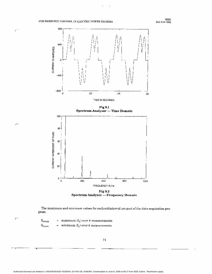
FOR HARMONIC CONTROL IN ELECTRIC POWER SYSTEMS
800
I
c
f
t -800 '
0 .02 .04 .06
101
$:
K
40
20
0
TIME IN SECONDS
IEEE Std 519-1992
0 300 600 900 1200
FREQUENCY IN Hz
Fig 9.2 Spectrum Analyzer - Frequency Domain
The maximum and minimum values for each subinterval are part of the data acquisition pro- gram.
Ihmax
Ihrnin
= maximum (Ih) over k measurements = minimum (Ih) over k measurements
71
1 I
Authorized licensed use limited to: UNIVERSIDADE FEDERAL DO RIO DE JANEIRO. Downloaded on June 8, 2009 at 06:27 from IEEE Xplore. Restrictions apply.
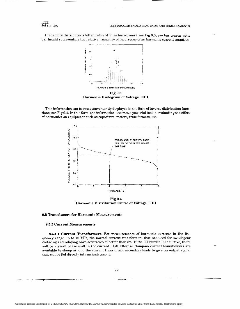
IEEE Std 519-1992 IEEE RECOMMENDED PRACTICES AND REQUIREMENTS
Probability distributions (often referred to as histograms), see Fig 9.3, are bar graphs with bar height representing the relative frequency of occurrence of an harmonic current quantity.
25 i
I
5 3 5 4
VOLTAGE THD IN PERCEM OF FUNDAMENTAL
Fig 9.3 Harmonic Histogram of Voltage THD
This information can be most conveniently displayed in the form of inverse distribution func- tions, see Fig 9.4. In this form, the information becomes a powerful tool in evaluating the effect of harmonics on equipment such as capacitors, motors, transformers, etc.
PROBABILITY
Fig 9.4 Harmonic Distribution Curve of Voltage THD
9.5 Transducers for Harmonic Measurements
9.5.1 Current Measurements
9.5.1.1 Current Transformers. For measurements of harmonic currents in the fre- quency range up to 10 kHz, the normal current transformers that are used for switchgear metering and relaying have accuracies of better than 3%. If the CT burden is inductive, there will be a small phase shift in the current. Hall Effect or clamp-on current transformers are available to clamp around the current transformer secondary leads to give an output signal that can be fed directly into an instrument.
72
Authorized licensed use limited to: UNIVERSIDADE FEDERAL DO RIO DE JANEIRO. Downloaded on June 8, 2009 at 06:27 from IEEE Xplore. Restrictions apply.

FOR HARMONIC CONTROL IN ELECTRIC POWER SYSTEMS IEEE
Std 519-1992
.- Shielded conductors (coaxial or triaxial cables) are a must for accurate results. Proper grounding and shielding procedures should be followed to reduce the pickup of parasitic volt- ages (see IEEE Std 518-1992 [Bll).
Coaxial cable is suitable for relatively short leads. If one is forced to measure a t a distance of tens to hundreds of meters, or if the sensor is near high voltage, the use of a voltage-to-fre- quency converter a t the sensor, a nonmetallic fibre optic cable for transmission, and a suitable frequency-to-voltage converter on the receiving end is very helpful for avoiding spurious signal pickup as well as for providing a safety barrier.
9.5.1.2 Search Coils. The magnetic field in the proximity of a conductor or coil carries information on the components of the current that generates the field. The amplitude of the induced harmonic voltage in a search coil, see Fig 9.5, is proportional to the effective coil area, the number of turns, the amplitude of the harmonic magnetic field perpendicular to the coil surface, and the frequency of the harmonics.
An a I y ze r
/i Fig 9.5 Sketch of a Search Coil
In such measurements, the measured magnetic field can arise from the contributions of more than one source. The magnetic field is inversely proportional from the distance to the source. Where it is possible to place the search coil at a small distance, d, from the conductor, while other conductors are located at distances larger than 2Od, the measurements of values in the chosen conductor are not substantially changed by fields of the other conductors.
9.5.1.3 Rogowski Coils or Maxwell’s Worms. These devices are coils that are wound on flexible plastic mandrels so that they can be used as clamp-on devices. They have no metal- lic core, so problems of core saturation are avoided in the presence of very large alternating currents, such as a 60 to 100 kA feed to an arc furnace, or direct currents.
9.5.2 Voltage Measurements. On low-voltage systems, the analyzer can be connected directly to the terminals where the voltage components must be determined. On medium and high-voltage systems, means of attenuation are used as described in the following para- graphs.
9.5.2.1 Magnetic Voltage Transformers. Magnetic voltage transformers, which are most easily available, are designed to operate a t fundamental frequency. Harmonic frequency resonance between winding inductances and capacitances can cause large ratio and phase errors. Fig 9.6 presents typical variations of transformer ratio vs. frequency. For harmonics of frequencies less than 5 kHz, the accuracy of most potential transformers is within 3%, which is satisfactory.
73
1 - ~~ r - .
Authorized licensed use limited to: UNIVERSIDADE FEDERAL DO RIO DE JANEIRO. Downloaded on June 8, 2009 at 06:27 from IEEE Xplore. Restrictions apply.
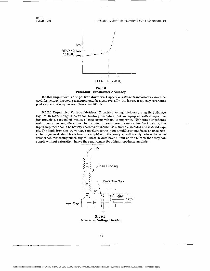
IEEE Std 519-1992 IEEE RECOMMENDED PRACTICES AND REQUIREMENTS
104%
1 6 10
FREQUENCY (kHz)
Fig 9.6 Potential Transformer Accuracy
9.5.2.2 Capacitive Voltage Transformers. Capacitive voltage transformers cannot be used for voltage harmonic measurements because, typically, the lowest frequency resonance peaks appear a t frequencies of less than 200 Hz.
9.5.2.3 Capacitive Voltage Dividers. Capacitive voltage dividers are easily built, see Fig 9.7. In high-voltage substations, bushing insulators that are equipped with a capacitive tap provide a convenient means of measuring voltage components. High-input-impedance instrumentation amplifiers must be included in such measurements. For best results, the input amplifier should be battery operated or should use a suitable shielded and isolated sup- ply. The leads from the low-voltage capacitors to the input amplifier should be as short as pos- sible. In general, short leads from the amplifier to the analyzer will greatly reduce the angle error when measuring phase angles. These devices have a limit on the burden that they can supply without saturation, hence the requirement for a high-impedance amplifier.
T
i HV
lnsul Bushing
Protective Gap cp
120v i Aux. Cap. I
Fig 9.7 Capacitive Voltage Divider
74
Authorized licensed use limited to: UNIVERSIDADE FEDERAL DO RIO DE JANEIRO. Downloaded on June 8, 2009 at 06:27 from IEEE Xplore. Restrictions apply.

FOR HARMONIC CONTROL IN ELECTRIC POWER SYSTEMS
10. Recommended Practices for Individual Consumers
IEEE Std 519-1992
10.1 General. This section describes the current distortion limits that apply to individual con- sumers of electrical energy. Section 11 describes the quality of electrical power that the pro- ducer should furnish to the consumer. These limitations are for the benefit of all parties involved. This recommendation supersedes IEEE Std 519-1981 and focuses on the point of common coupling (PCC) with the consumer-utility interface. I t specifically excludes those high-voltage direct current (HVDC) facilities and static var control (SVC) systems owned and operated by the utility. Such installations, which are generally large in MVA ratings with potentially substantial impacts on the entire power system operation, justify more extensive harmonic studies and a more conservative approach to harmonic control than those recom- mended here.
It would be ideal if it were possible to control harmonics to such an extent that harmonic ef- fects caused by connection of harmonic-producing loads were nil a t every point in the entire system encompassing the consumer’s own circuit, the utility circuit, and other consumers’ cir- cuits. In reality, however, economic factors and the effectiveness of the harmonic control must be balanced; and some harmonic effects are unavoidable a t some points in the system. The rec- ommendation described in this document attempts to reduce the harmonic effects at any point in the entire system by establishing limits on certain harmonic indices (currents and voltages) at the point of common coupling (PCC), a point of metering, or any point as long as both the utility and the consumer can either access the point for direct measurement of the harmonic indices meaningful to both or can estimate the harmonic indices a t point of interference (POI) through mutually agreeable methods. Within an industrial plant, the PCC is the point between the nonlinear load and other loads.
Good harmonic indices are characterized by the following:
(1) The values given by the harmonic indices should be physically meaningful and strongly correlated to the severity of the harmonic effects.
(2) It should be possible to determine by measurements whether or not the limits of the harmonic indices are met.
(3) Harmonic indices should be simple and practical so that they can be widely used with ease.
Recommended harmonic indices are
(1) Depth of notches, total notch area, and distortion (RSS) of bus voltage distorted by commutation notches (low-voltage systems)
(2) Individual and total voltage distortion (3) Individual and total current distortion
As described in Section 6, the harmonic effects differ substantially depending on the charac- teristics of the equipment affected. Therefore, the severity of the harmonic effects imposed on all types of equipment cannot be perfectly correlated to a few, simple indices. Moreover, the harmonic characteristics of the utility circuit seen from the PCC often are not known accurate- ly. Accordingly, good engineering judgments are required on a case-by-case basis, and this rec- ommendation in no way overrides such judgments.
Strict adherence to the recommended harmonic limits will not always prevent problems from arising, particularly when the limits are approached. It is reasonable to consider that system changes will often justify reexamination. Harmonic measurements should be performed from time to time to determine system behavior and equipment performance. The consumer should confirm:
75
Authorized licensed use limited to: UNIVERSIDADE FEDERAL DO RIO DE JANEIRO. Downloaded on June 8, 2009 at 06:27 from IEEE Xplore. Restrictions apply.
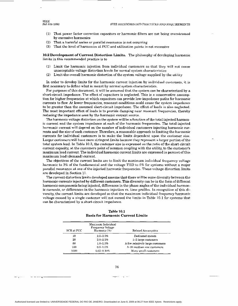
IEEE Std 519-1992 IEEE RECOMMENDED PRACTICES AND REQUIREMENTS
(1) That power factor correction capacitors or harmonic filters are not being overstressed by excessive harmonics
(2) That a harmful series or parallel resonance is not occurring (3) That the level of harmonics at PCC and utilization points is not excessive
10.2 Development of Current Distortion Limits. The philosophy of developing harmonic limits in this recommended practice is to
(1) Limit the harmonic injection from individual customers so that they will not cause unacceptable voltage distortion levels for normal system characteristics
(2) Limit the overall harmonic distortion of the system voltage supplied by the utility
In order to develop limits for the harmonic current injection by individual customers, it is first necessary to define what is meant by normal system characteristics.
For purposes of this document, it will be assumed that the system can be characterized by a short-circuit impedance. The effect of capacitors is neglected. This is a conservative assump- tion for higher frequencies at which capacitors can provide low-impedance paths for harmonic currents to flow. At lower frequencies, resonant conditions could cause the system impedance to be greater than the assumed short-circuit impedance. The effect of loads is also neglected. The most important effect of loads is to provide damping near resonant frequencies, thereby reducing the impedance seen by the harmonic current source.
The harmonic voltage distortion on the system will be a function of the total injected harmon- ic current and the system impedance at each of the harmonic frequencies. The total injected harmonic current will depend on the number of individual customers injecting harmonic cur- rents and the size of each customer. Therefore, a reasonable approach to limiting the harmonic currents for individual customers is to make the limits dependent upon the customer size. Larger customers will have more stringent limits because they represent a larger portion of the total system load. In Table 10.3, the customer size is expressed as the ratio of the short-circuit current capacity, at the customers point of common coupling with the utility, to the customer’s maximum load current. The individual harmonic current limits are expressed in percent of this maximum load (demand) current.
The objectives of the current limits are to limit the maximum individual frequency voltage harmonic to 3% of the fundamental and the voltage THD to 5% for systems without a major parallel resonance at one of the injected harmonic frequencies. These voltage distortion limits are developed in Section 11.
The current distortion limits developed assume that there will be some diversity between the harmonic currents injected by different customers. This diversity can be in the form of different harmonic components being injected, differences in the phase angles of the individual harmon- ic currents, or differences in the harmonic injection vs. time profiles. In recognition of this di- versity, the current limits are developed so that the maximum individual frequency harmonic voltage caused by a single customer will not exceed the limits in Table 10.1 for systems that can be characterized by a short-circuit impedance.
Table 10.1 Basis for Harmonic Current Limits
Maximum Individual Frequency Voltage
SCR at PCC Harmonic (%) Related Assumption
10 2.5-3.0% Dedicated system 20 2 .O-2.5% 1-2 large customers 50 1.0-1.5% A few relatively large customers 100 0.5-1.0% 5-20 medium size customers 1000 0.05-0.10% Many small customers
76
Authorized licensed use limited to: UNIVERSIDADE FEDERAL DO RIO DE JANEIRO. Downloaded on June 8, 2009 at 06:27 from IEEE Xplore. Restrictions apply.
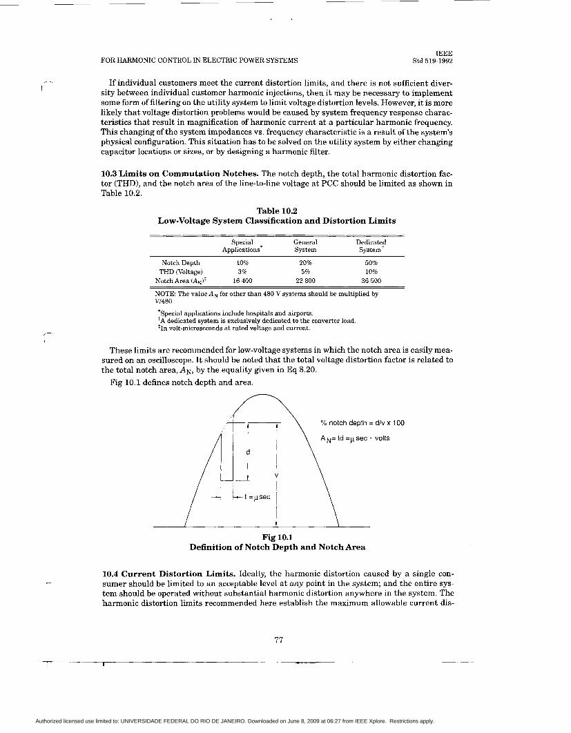
FOR HARMONIC CONTROL IN ELECTRIC POWER SYSTEMS IEEE
Std 519-1992
,-
If individual customers meet the current distortion limits, and there is not sufficient diver- sity between individual customer harmonic injections, then it may be necessary to implement some form of filtering on the utility system to limit voltage distortion levels. However, it is more likely that voltage distortion problems would be caused by system frequency response charac- teristics that result in magnification of harmonic current at a particular harmonic frequency. This changing of the system impedances vs. frequency characteristic is a result of the system's physical configuration. This situation has to be solved on the utility system by either changing capacitor locations or sizes, or by designing a harmonic filter.
10.3 Limits on Commutation Notches. The notch depth, the total harmonic distortion fac- tor (THD), and the notch area of the line-to-line voltage a t PCC should be limited as shown in Table 10.2.
Table 10.2 Low-Voltage System Classification and Distortion Limits
Special General Dedicated Applications* System System'
~~ ~~~~
Notch Depth 10% 20% 50%
Notch Area (A,)$ 16 400 22 800 36 500 THD (Voltage) 3% 5% 10%
NOTE: The value A, for other than 480 V systems should be multiplied by VI480
*Special applications include hospitals and airports. +A dedicated system is exclusively dedicated to the converter load *In volt-microseconds a t rated voltage and current.
These limits are recommended for low-voltage systems in which the notch area is easily mea- sured on an oscilloscope. I t should be noted that the total voltage distortion factor is related to the total notch area, AN, by the equality given in Eq 8.20.
Fig 10.1 defines notch depth and area.
% notch depth = d/v x 100
AN= td =p sec . volts
i \ Fig 10.1
Definition of Notch Depth and Notch Area
10.4 Current Distortion Limits. Ideally, the harmonic distortion caused by a single con- sumer should be limited to an acceptable level a t any point in the system; and the entire sys- tem should be operated without substantial harmonic distortion anywhere in the system. The harmonic distortion limits recommended here establish the maximum allowable current dis-
77
1 I I
Authorized licensed use limited to: UNIVERSIDADE FEDERAL DO RIO DE JANEIRO. Downloaded on June 8, 2009 at 06:27 from IEEE Xplore. Restrictions apply.
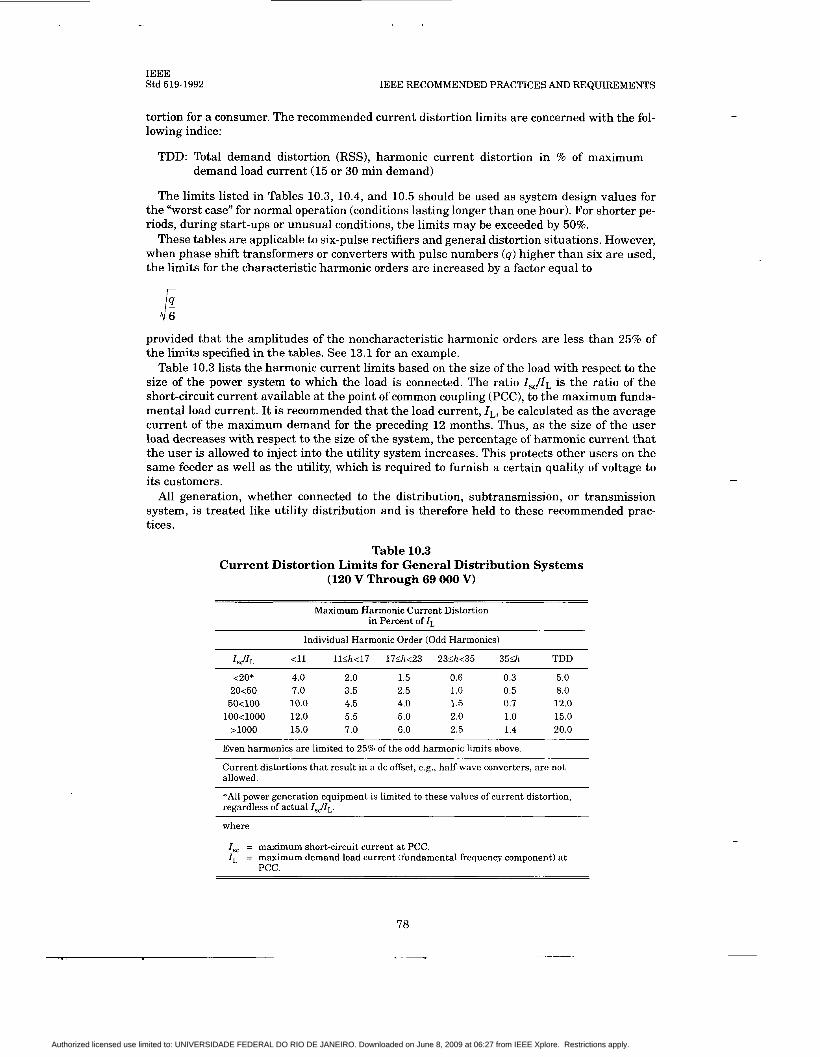
IEEE Std 519-1992 IEEE RECOMMENDED PRACTICES AND REQUIREMENTS
tortion for a consumer. The recommended current distortion limits are concerned with the fol- lowing indice:
TDD: Total demand distortion (RSS), harmonic current distortion in % of maximum demand load current (15 or 30 min demand)
The limits listed in Tables 10.3, 10.4, and 10.5 should be used as system design values for the “worst case” for normal operation (conditions lasting longer than one hour). For shorter pe- riods, during start-ups or unusual conditions, the limits may be exceeded by 50%.
These tables are applicable to six-pulse rectifiers and general distortion situations. However, when phase shift transformers or converters with pulse numbers (4) higher than six are used, the limits for the characteristic harmonic orders are increased by a factor equal to
provided that the amplitudes of the noncharacteristic harmonic orders are less than 25% of the limits specified in the tables. See 13.1 for an example.
Table 10.3 lists the harmonic current limits based on the size of the load with respect to the size of the power system to which the load is connected. The ratio I J I L is the ratio of the short-circuit current available at the point of common coupling (PCC), to the maximum funda- mental load current. I t is recommended that the load current, I L , be calculated as the average current of the maximum demand for the preceding 12 months. Thus, as the size of the user load decreases with respect to the size of the system, the percentage of harmonic current that the user is allowed to inject into the utility system increases. This protects other users on the same feeder as well as the utility, which is required to furnish a certain quality of voltage to its customers.
All generation, whether connected to the distribution, subtransmission, or transmission system, is treated like utility distribution and is therefore held to these recommended prac- tices.
Table 10.3 Current Distortion Limits for General Distribution Systems
(120 V Through 69 000 V)
Maximum Harmonic Current Distortion in Percent of I L
Individual Harmonic Order (Odd Harmonics)
ZSJZL <11 ll<h<17 17&<23 23<h<35 35Sh TDD
<20* 4.0 2.0 1.5 0.6 0.3 5.0 20<50 7.0 3.5 2.5 1.0 0.5 8.0 50<100 10.0 4.5 4.0 1.5 0.7 12.0
100<1000 12.0 5.5 5.0 2.0 1.0 15.0 >loo0 15.0 7.0 6.0 2.5 1.4 20.0
Even harmonics are limited to 25% of the odd harmonic limits above.
Current distortions that result in a dc offset, e.g., half-wave converters, are not allowed.
*All power generation equipment is limited to these values of current distortion, regardless of actual ZsJZL.
where
I,, = maximum short-circuit current a t PCC. I, = maximum demand load current (fundamental frequency component) a t
PCC.
78
Authorized licensed use limited to: UNIVERSIDADE FEDERAL DO RIO DE JANEIRO. Downloaded on June 8, 2009 at 06:27 from IEEE Xplore. Restrictions apply.
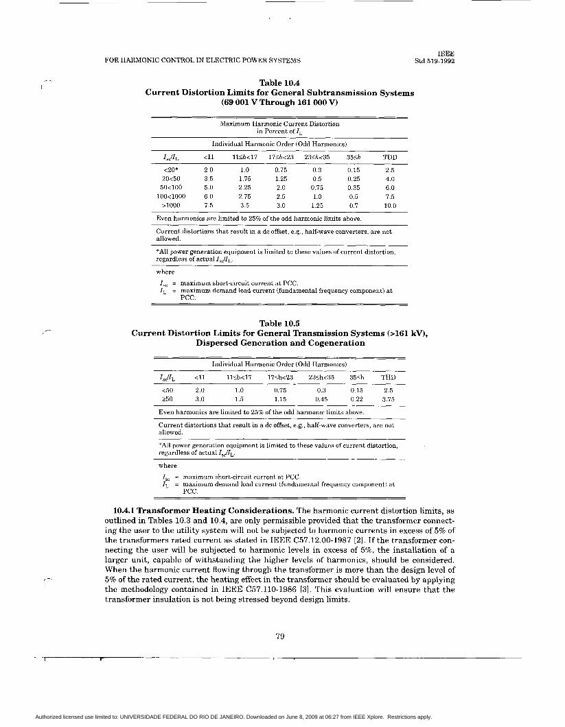
FOR HARMONIC CONTROL IN ELECTRIC POWER SYSTEMS
Table 10.4 Current Distortion Limits for General Subtransmission Systems
(69 001 V Through 161 000 V)
Maximum Harmonic Current Distortion in Percent of ZL
Individual Harmonic Order (Odd Harmonics)
I d L <11 l l S k 1 7 17&<23 23Sh<35 35& TDD ~~
<20* 2.0 1.0 0.75 0.3 0.15 2.5 20<50 3.5 1.75 1.25 0.5 0.25 4.0
5 0 4 0 0 5.0 2.25 2.0 0.75 0.35 6.0 100<1000 6.0 2.75 2.5 1.0 0.5 7.5
>loo0 7.5 3.5 3.0 1.25 0.7 10.0
Even harmonics are limited to 25% of the odd harmonic limits above.
Current distortions that result in a dc offset, e.g., half-wave converters, are not allowed.
*All power generation equipment is limited to these values of current distortion, regardless of actual ZsJZL.
where
I,, = maximum short-circuit current a t PCC. I , = maximum demand load current (fundamental frequency component) a t
PCC.
IEEE Std 519-1992
Table 10.5 Current Distortion Limits for General Transmission Systems b161 kV),
Dispersed Generation and Cogeneration
Individual Harmonic Order (Odd Harmonics)
Is,jIL <11 1 1 4 ~ 1 7 17Sh<23 23Sh<35 35Sh THD ~ ~~
4 0 2.0 1.0 0.75 0.3 0.15 2.5 250 3.0 1.5 1.15 0.45 0.22 3.75
Even harmonics are limited to 25% of the odd harmonic limits above.
Current distortions that result in a dc offset, e.g., half-wave converters, are not allowed.
*All power generation equipment is limited to these values of current distortion, regardless of actual IsJZL,
c
where
I,, = maximum short-circuit current at PCC. ZL = maximum demand load current (fundamental frequency component) a t
PCC.
10.4.1 Transformer Heating Considerations. The harmonic current distortion limits, as outlined in Tables 10.3 and 10.4, are only permissible provided that the transformer connect- ing the user to the utility system will not be subjected to harmonic currents in excess of 5% of the transformers rated current as stated in IEEE C57.12.00-1987 [21. If the transformer con- necting the user will be subjected to harmonic levels in excess of 5%, the installation of a larger unit, capable of withstanding the higher levels of harmonics, should be considered. When the harmonic current flowing through the transformer is more than the design level of 5% of the rated current, the heating effect in the transformer should be evaluated by applying the methodology contained in IEEE C57.110-1986 [31. This evaluation will ensure that the transformer insulation is not being stressed beyond design limits.
79
1 I
Authorized licensed use limited to: UNIVERSIDADE FEDERAL DO RIO DE JANEIRO. Downloaded on June 8, 2009 at 06:27 from IEEE Xplore. Restrictions apply.
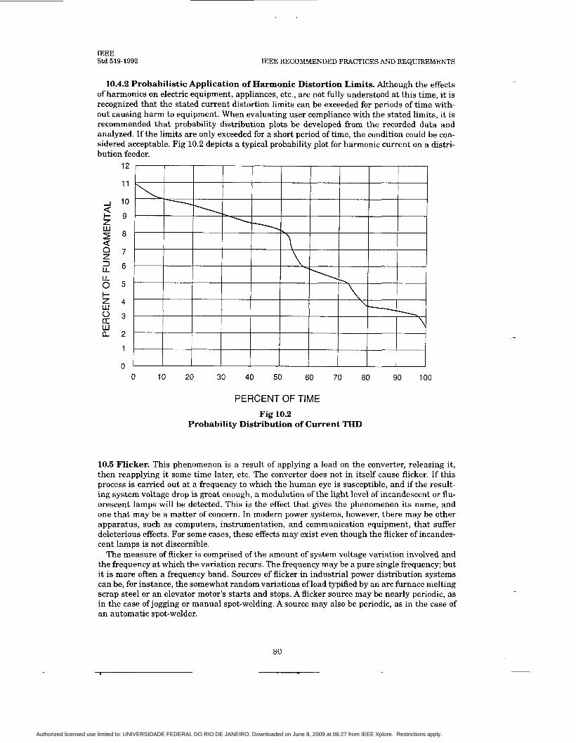
IEEE Std 519-1992 IEEE RECOMMENDED PRACTICES AND REQUIREMENTS
10.4.2 Probabilistic Application of Harmonic Distortion Limits. Although the effects of harmonics on electric equipment, appliances, etc., are not fully understood a t this time, it is recognized that the stated current distortion limits can be exceeded for periods of time with- out causing harm to equipment. When evaluating user compliance with the stated limits, it is recommended that probability distribution plots be developed from the recorded data and analyzed. If the limits are only exceeded for a short period of time, the condition could be con- sidered acceptable. Fig 10.2 depicts a typical probability plot for harmonic current on a distri- bution feeder.
12
11
10
I - 9 z 8 W
2
5
8 5
s 3
0 7 Z LL I 6
F z 4 W
w Q 2
1
0 0 10 20 30 40 50 60 70 80 90 100
PERCENT OF TIME Fig 10.2
Probability Distribution of Current THD
10.5 Flicker. This phenomenon is a result of applying a load on the converter, releasing it, then reapplying it some time later, etc. The converter does not in itself cause flicker. If this process is carried out at a frequency to which the human eye is susceptible, and if the result- ing system voltage drop is great enough, a modulation of the light level of incandescent or flu- orescent lamps will be detected. This is the effect that gives the phenomenon its name, and one that may be a matter of concern. In modern power systems, however, there may be other apparatus, such as computers, instrumentation, and communication equipment, that suffer deleterious effects. For some cases, these effects may exist even though the flicker of incandes- cent lamps is not discernible.
The measure of flicker is comprised of the amount of system voltage variation involved and the frequency at which the variation recurs. The frequency may be a pure single frequency; but it is more often a frequency band. Sources of flicker in industrial power distribution systems can be, for instance, the somewhat random variations of load typified by an arc furnace melting scrap steel or an elevator motor’s starts and stops. A flicker source may be nearly periodic, as in the case of jogging or manual spot-welding. A source may also be periodic, as in the case of an automatic spot-welder.
80
Authorized licensed use limited to: UNIVERSIDADE FEDERAL DO RIO DE JANEIRO. Downloaded on June 8, 2009 at 06:27 from IEEE Xplore. Restrictions apply.

c
1 2 3 6 10 2 0 3 0 1 2 4 6 10 2 0 3 0 60
FOR HARMONIC CONTROL IN ELECTRIC POWER SYSTEMS
2 3 4 6 1 0 1 5
IEEE Std 519-1992
Flicker intensity (that is, the magnitude of the voltage variation) is determined by the power system source impedance and load peak power requirements. When planning to install pulsed converters, the effects of the pulse load on other parts of the distribution system should be cal- culated. This requires knowledge of
(1) The voltampere requirements of the pulsed load, magnitude, and frequency (2) The impedance of the source(s) within the distribution system back to a supply of such
stiffness that variations can be considered truly inconsequential (3) Whether or not apparatus that are susceptible to flicker are within the exposed distri-
bution sector and their degree of susceptibility
10.5.1 Limits of Flicker. Frequently, the degree of susceptibility is not readily determin- able. Fig 10.3 is offered as a guide for planning for such applications. This curve is derived from empirical studies made by several sources. There are several such curves existing that have approximately the same vertical scale.
House Pumps Sump Pumps
AIC Equipment Theatrical Lighting
Domestic Refrigerators Oil Burners
- c - I - c +\- - e-- - t 4 - -
Single Elevator
Cranes Y-Delta Changes on
Elevatw-Motor-Generatof Sets X-Ray Equipment
HoiJts
sews Group Elevators
Reciprocating Pumps Compressors
Automatic Spot-Welders
I 1 L i n e s comuosi te c u r v e s o f v o l t a a e f l i c k e r s t u d i e s SI
b v Genera l E l e c t r i c Company. Genera l E l e c t r i c Rev iew -$gust 1925; Kavsas . . C i t y . - Power . - -. 6 - L i g h t . Canpany. . _ _ . E l e c t r i c a l World, May IY. I Y 3 4 ; I L U L m i t t e e . t t l ,
October 24. 1934, Ch icago; D e t r o i t Ed ison Canpany; West Pennsy lvan ia Power Company; P u b l i c S e r v i c e Company of N o r t h e r n I l l i n o i s .
D o t t e d L i n e s v o l t a g e f l i c k e r a l l o w e d by two u t i l i t i e s .
Fig 10.3 Maximum Permissible Voltage Fluctuations
81
, r - ,.
~ _ _ _ _
Authorized licensed use limited to: UNIVERSIDADE FEDERAL DO RIO DE JANEIRO. Downloaded on June 8, 2009 at 06:27 from IEEE Xplore. Restrictions apply.

IEEE Std 519-1992 IEEE RECOMMENDED PRACTICES AND REQUIREMENTS
10.5.2 Compensation for Flicker. Methods for compensating for existing or potential flicker are much the same as those used to compensate for subtransient disturbances, such as those evidenced by notching or harmonic currents. The simplest and generally most effective technique is to provide a sufficiently stiff source of power so that the effect is negligible at the point where the flicker source is tapped off from the rest of the power distribution system. Compensatory methods are used to emulate the stiff source. Series capacitors, thyristor switching of inductors with shunt capacitors (static var control), saturating shunt inductors, and thyristor switched shunt capacitors may be used to maintain a relatively steady voltage at the tie point. As in cases in which such schemes are used to provide subtransient compen- sation, the possibility of overall distribution system instability must be thoroughly investi- gated before one can confidently apply the technique.
Note that the curves in Fig 10.3 are being revised and should be available by 1995.
Authorized licensed use limited to: UNIVERSIDADE FEDERAL DO RIO DE JANEIRO. Downloaded on June 8, 2009 at 06:27 from IEEE Xplore. Restrictions apply.
FOR HARMONIC CONTROL IN ELECTRIC POWER SYSTEMS IEEE
Std 519-1992
c ll. Recommended Practices for Utilities
ll.1 General. The factors that define the quality of electrical service include harmonic distor- tion in addition to more familiar factors such as safety of service (e.g., surge protection and step-and-touch voltage), service continuity, voltage regulation, and flicker. The distortion lim- its recommended in this section establish the maximum voltage distortion at the point of com- mon coupling (PCC) with each consumer.
If the limits are exceeded, the following steps may be taken:
Perform harmonic measurements at selected points within the utility circuit, including the PCC, and look for consumers with converters operating with current distortion beyond the limits. If identified, such consumers should be asked to keep the harmonic distortion within the recommended limits by installing filters, by reducing harmonic generation, or through other means. Install filters to control the harmonics. Install a new feeder. This is effective in stiffening the source and isolating the har- monic problems. However, it is not always economically feasible.
It should be noted that it is possible to add new converter loads t o a circuit already polluted with harmonics to the recommended limits as long as properly designed filters are also pro- vided.
Il.2 Addition of Harmonics. The waveshape of the converter ac current is determined by the delay angle a t which commutation starts and by the commutating overlap angle. Conse- quently, the harmonic current components generated by one converter may not be in phase with the respective harmonic current components generated by another converter connected to the same feeder circuit. The same can be said for the respective harmonic impedance volt- age drop components. The addition of the harmonic voltage and current contributions from multiple converters is conceptually simple. Kirchoffs voltage and current laws are applied t o the phasers of each harmonic frequency. In practice, the rigorous addition of the harmonic components is likely to be impossible. A prohibitive amount of phasing data would have to be collected and then analyzed statistically for time-of-day variations.
A simple, approximate, and conservative method of addition is recommended; namely, solv- ing the circuit for each harmonic source separately to determine the branch currents and node voltages caused by the harmonic source, and then arithmetically adding them up. Coincidence factors of the converter loads can be used to refine the addition if such data are readily avail- able.
Harmonic measurements should be performed from time to time at selected points at which a high level of harmonic distortion is suspected to determine the system behavior and confirm
1-
(1) That utility capacitors, filters, cables, and transformers are not being overstressed by excessive harmonics
(2) That a harmful degree of series or parallel resonance is not occurring (3) That the level of harmonics are within the limits
The harmonic analysis based on the coincidence factors of converter loads should be made to evaluate the measurement results and to extrapolate the results for the assessment of the effects of new converters to be installed. Sole reliance on an extensive analytical addition of harmonics is not recommended.
Il.3 Short-Duration Harmonics. Devices such as a thyristor-controlled drive applied to a rolling mill generate short-duration bursts of harmonic currents as the material passes through the mill. Generation of intermittent harmonics and the resulting voltage stress on
83
Authorized licensed use limited to: UNIVERSIDADE FEDERAL DO RIO DE JANEIRO. Downloaded on June 8, 2009 at 06:27 from IEEE Xplore. Restrictions apply.

IEEE Std 519-1992 IEEE RECOMMENDED PRACTICES AND REQUIREMENTS
the capacitors, the transformers, and other power apparatus is sometimes more tolerable than the stress caused by the constant generation of harmonics. Intermittent harmonics and constant harmonics will cause similar effects as far as harmonic interference to the control circuits, the communication circuits, and the electronic equipment is concerned. It is likely, however, that flicker is the major problem in this case and that harmonic problems are sec- ondary. A solution to the flicker problem may well eliminate the harmonic problems.
11.4 Abnormal Conditions for Harmonic Problems. Some of the less common condi- tions known to cause harmonic problems are described here. They are the natural reso- nance of a transmission line, overexcitation of transformers, and harmonic resonance in the zero-sequence circuit.
Each transmission line has many natural resonant frequencies determined by its length, its geometry, and its termination. The input impedance of a transmission line can become close to zero and resistive (series resonance) or infinitely large (parallel resonance) at the natural res- onant frequencies. If a series resonance frequency is close to one of the dominant harmonics generated by converters, there is a risk of severe telephone interference. The problem can be corrected by changing the natural frequency of the transmission line (by changing the termi- nation or the line length) or by preventing the harmonic current flow into the line with a series blocking filter, a shunt filter, or both. Unfortunately, these solutions are often expen- sive.
Because of transformer core characteristics, overexcited transformers generate odd order harmonics. There is a tendency to operate high-voltage circuits with voltage that is substan- tially higher than nominal by switching in capacitor banks well ahead of daily load increase. This assures a desired load flow and voltage stability, but can cause harmonic problems. Excess reactive power during light load conditions can cause similar problems.
A harmonic resonance can occur in the zero-sequence circuit under the following conditions:
(1) Wye-connected generator neutrals are grounded through reactors. (2) Generators are connected to the feeders directly or through transformers with wye-
connected windings, on the generator side, that are grounded solidly or through neu- tral reactors.
(3) Power factor correction capacitors connected in a grounded-wye arrangement are applied along a feeder.
These conditions may be satisfied in small isolated systems. The generator voltage always contains zero-sequence harmonic voltages. These harmonic voltages act like voltage sources because of the small internal impedances involved. The harmonic voltage sources are con- nected to a series combination of an inductive reactance (generator reactance, transformer reactance, feeder reactance, and neutral grounding reactance) and a capacitive reactance. If the two are similar in magnitude at one of the harmonic frequencies, a large amount of har- monic current will flow in the loop and can cause unusual problems such as high step-and- touch voltages, erroneous operation of kwh meters for single-phase consumers, and false operation of ground overcurrent relays. One solution is to break the ground loop by changing grounding schemes for generators and capacitors. Proper use of delta-connected windings of step-up transformers also breaks the ground loop.
11.5 Voltage Distortion Limits. The recommended voltage distortion limits (see Table 11.1) are concerned with the following indice:
THD: Total (RSS) harmonic voltage distortion in percent of nominal fundamental fre- quency voltage.
84
Authorized licensed use limited to: UNIVERSIDADE FEDERAL DO RIO DE JANEIRO. Downloaded on June 8, 2009 at 06:27 from IEEE Xplore. Restrictions apply.
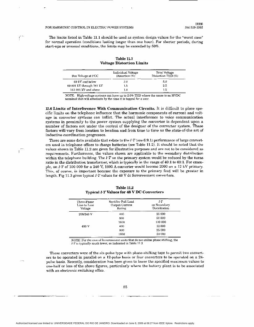
f-
FOR HARMONIC CONTROL IN ELECTRIC POWER SYSTEMS IEEE
Std 519-1992
The limits listed in Table 11.1 should be used as system design values for the “worst case” for normal operation (conditions lasting longer than one hour). For shorter periods, during start-ups or unusual conditions, the limits may be exceeded by 50%.
Table 11.1 Voltage Distortion Limits
Individual Voltage Total Voltage Bus Voltage a t PCC Distortion (%) Distortion THD (%)
69 kV and below 3.0 5.0 69.001 kV through 161 kV 1.5 2.5
161.001 kV and above 1.0 1.5
NOTE: High-voltage systems can have up to 2.0% THD where the cause is an HVDC terminal that will attenuate by the time it is tapped for a user.
ll.6 Limits of Interference With Communication Circuits. It is difficult to place spe- cific limits on the telephone influence that the harmonic components of current and volt- age in converter systems can inflict. The actual interference to voice communication systems in proximity to the power system supplying the converter is dependent upon a number of factors not under the control of the designer of the converter system. These factors will vary from location to location and from time to time a s the state-of-the art of inductive coordination progresses.
There are some data available that relate to the IaT (see 6.9.1) performance of large convert- ers used in telephone offices t o charge batteries (see Table 11.2). It should be noted that the values shown in Table 11.2 are given for illustrative purposes and are not to be considered as requirements. Furthermore, the values shown are applicable to the secondary distribution within the telephone building. The I.T on the primary system would be reduced by the turns ratio in the distribution transformer, which is typically in the range of 40:l to 60:l. For exam- ple, an I-T of 100 000 for a 240 V, 1600 A converter would become 2000 on a 12 kV primary. This, of course, is important because the exposure to the primary feed will be greater in length. Fig 11.3 gives typical I.T values for 48 V dc ferroresonant converters.
Table 11.2 Typical I-T Values for 48 V DC Converters
Three-phase Rectifier Full Load Z.T Line-to-Line Output Current on Secondary
Voltage Rating Distribution
2081240 V
480 V
400 800 1600 400 800 1600
25 000 50 000 100 000 12 000 25 000 50 000
NOTE: For the case of ferroresonant units that do not utilize phase shifting, the I.T is typically much lower, as indicated in Table 11.3.
These converters were of the six-pulse type with phase-shifting taps to permit two convert- ers to be operated in parallel on a 12-pulse basis or four converters to be operated on a 24- pulse basis. Recently, consideration has been given to lower the specified maximum values to one-half or less of the above figures, particularly where the battery plant is to be associated with an electronic switching office.
85
Authorized licensed use limited to: UNIVERSIDADE FEDERAL DO RIO DE JANEIRO. Downloaded on June 8, 2009 at 06:27 from IEEE Xplore. Restrictions apply.
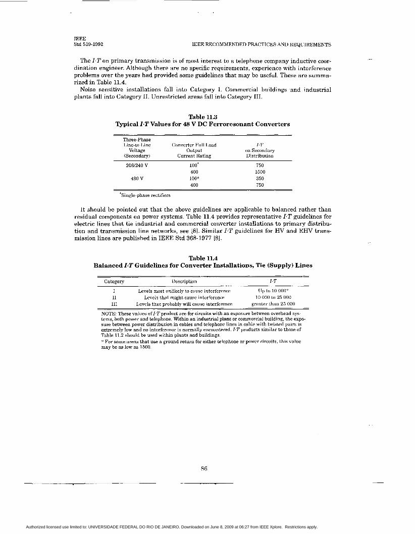
IEEE Std 519-1992 IEEE RECOMMENDED PRACTICES AND REQUIREMENTS
The Z.T on primary transmission is of most interest to a telephone company inductive coor- dination engineer. Although there are no specific requirements, experience with interference problems over the years had provided some guidelines that may be useful. These are summa- rized in Table 11.4.
Noise sensitive installations fall into Category I. Commercial buildings and industrial plants fall into Category 11. Unrestricted areas fall into Category 111.
Table 11.3 Typical I-T Values for 48 V DC Ferroresonant Converters
Three-phase Line-to-Line Converter Full Load I.T
Voltage output on Secondary (Secondary) Current Rating Distribution
2081240 V loo* 750 400 1500
480 v loo* 350 400 750
*Single-phase rectifiers
It should be pointed out that the above guidelines are applicable to balanced rather than residual components on power systems. Table 11.4 provides representative Z.T guidelines for electric lines that tie industrial and commercial converter installations to primary distribu- tion and transmission line networks, see 181. Similar Z.T guidelines for H V and EHV trans- mission lines are published in IEEE Std 368-1977 [81.
Table 11.4 Balanced I-T Guidelines for Converter Installations, Tie (Supply) Lines
Category Description 1.T
I I1 I11
Levels most unlikely to cause interference Levels that might cause interference
u p to 10 ooo* 10 000 to 25 000
greater than 25 000 Levels that probably will cause interference
NOTE: These values of I.T product are for circuits with an exposure between overhead sys- tems, both power and telephone. Within an industrial plant or commercial building, the expo- sure between power distribution in cables and telephone lines in cable with twisted pairs is extremely low and no interference is normally encountered. 1.T products similar to those of Table 11.2 should be used within plants and buildings. * For some areas that use a ground return for either telephone or power circuits, this value may be as low as 1500.
86
Authorized licensed use limited to: UNIVERSIDADE FEDERAL DO RIO DE JANEIRO. Downloaded on June 8, 2009 at 06:27 from IEEE Xplore. Restrictions apply.

FOR HARMONIC CONTROL IN ELECTRIC POWER SYSTEMS
12. Recommended Methodology for Evaluating New Harmonic Sources
IEEE Std 519-1992
12.1 General. A general harmonic analysis procedure should be adopted as part of the system planning process. This procedure should be employed whenever known large har- monic sources exist on a system or when significant dispersed generators are being pro- posed. In the future, the harmonic analysis procedure may be part of the general design process due to the increasing level of harmonic generation associated with normal system loads. This general procedure is described in the following sections.
12.2 Identifying Harmonic Analysis Objectives. The overall harmonic analysis procedure will depend on the specific objectives of the study being performed. Possible objectives include the following:
(1) To characterize existing harmonic levels (2) To evaluate a system problem (failure, telephone interference) that may be related to
harmonics (3) To evaluate impact of a new harmonic producing load, device, or dispersed generator
on the system (4) To design harmonic control equipment
12.3 Developing Initial System ModeUPerform Preliminary Simulations. Preliminary simulations should be performed to identify expected harmonic levels and system response characteristics. These simulations should be performed for different system conditions t o identify the conditions of potential concern. The initial system model should be based on the modeling guidelines outlined in 8.3.
The potential impact of individual harmonic sources should be evaluated at this point. If the projected harmonic levels based on the guidelines outlined in this document are accept- able, then no further investigation may be required. If excessive harmonic distortion is antici- pated, further analysis and the development of solutions to the problem is required.
12.4 Performing Harmonic Measurements. Measurements will continue to be an impor- tant part of many harmonic investigations. For some situations, it may be possible to accom- plish all of the objectives with simulations. However, measurements will often be needed for any of the following reasons:
(1) To characterize existing background harmonic levels, including statistical characteris- tics
(2) To determine harmonic source characteristics (3) To validate simulation models
If a converter is in continuous conduction, it may be used to determine system inductance. The minimum dc current (commutating current) and the notch area are measured with an oscilloscope. The per phase inductance can be determined from these values. (See 8.5.1.)
12.5 Performing Detailed Simulations. Detailed simulations should utilize any measure- ment results for model validation and then should expand beyond the specific system condi- tions associated with the field tests. All possible system configurations can be studied, and different load conditions can be evaluated. The simulations should expand on the measure- ments in the following ways:
(1) Analyze different system conditions, including possible future conditions. (2) Determine the effect of new harmonic sources on the system. (3) Simulate equipment parameter and operating procedures for harmonic control.
87
r - .
Authorized licensed use limited to: UNIVERSIDADE FEDERAL DO RIO DE JANEIRO. Downloaded on June 8, 2009 at 06:27 from IEEE Xplore. Restrictions apply.

IEEE Std 519-1992 IEEE RECOMMENDED PRACTICES AND REQUIREMENTS
12.6 Developing Solutions to Harmonic Problems. Simulations will be used to develop solutions to any potential harmonic problems. The solutions can include
(1) Operating restrictions (2) Changed system configurations (3) Harmonic filters (4) Reduced coupling to telephone and communication circuits
88
Authorized licensed use limited to: UNIVERSIDADE FEDERAL DO RIO DE JANEIRO. Downloaded on June 8, 2009 at 06:27 from IEEE Xplore. Restrictions apply.
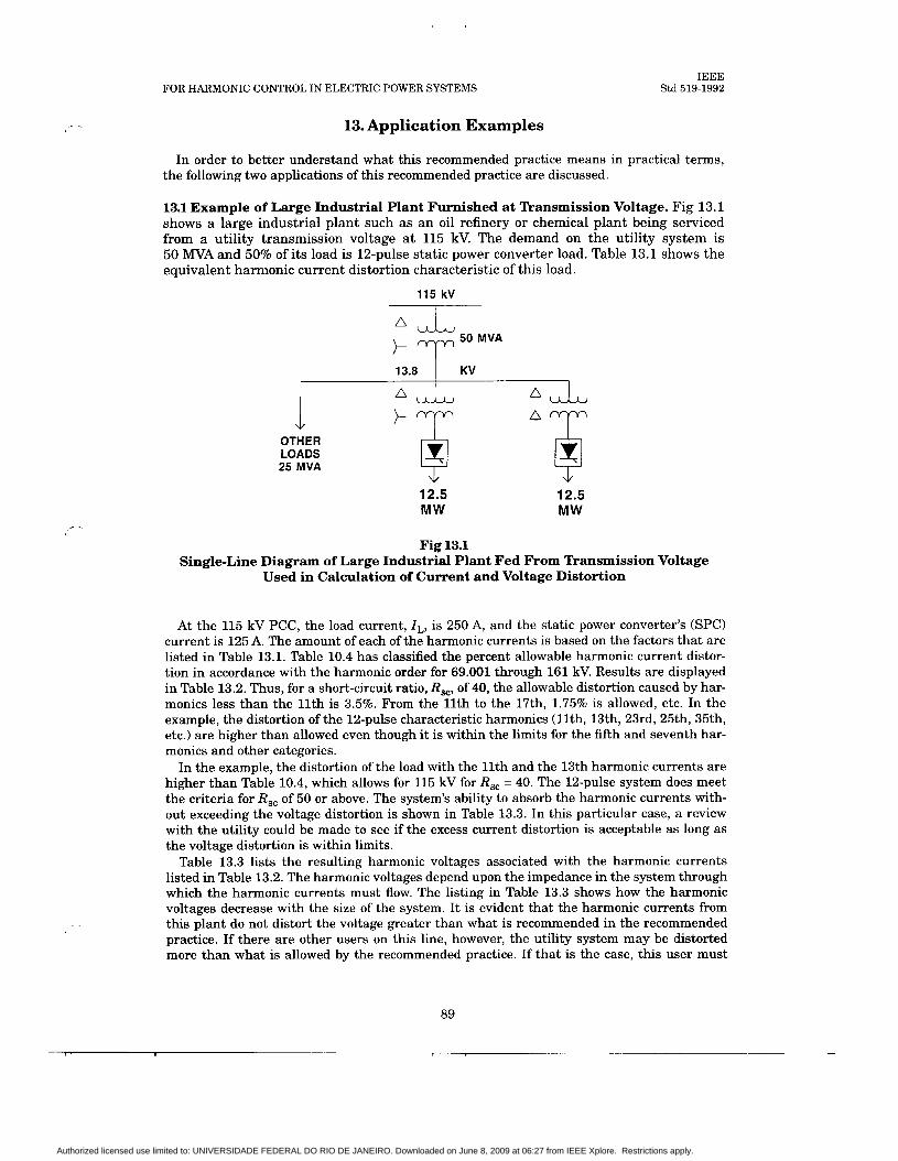
FOR HARMONIC CONTROL IN ELECTRIC POWER SYSTEMS IEEE
Std 519-1992
13. Application Examples
In order to better understand what this recommended practice means in practical terms, the following two applications of this recommended practice are discussed.
13.1 Example of Large Industrial Plant Furnished at Transmission Voltage. Fig 13.1 shows a large industrial plant such as a n oil refinery or chemical plant being serviced from a utility transmission voltage at 115 kV. The demand on the utility system is 50 MVA and 50% of its load is 12-pulse static power converter load. Table 13.1 shows the equivalent harmonic current distortion characteristic of this load.
115 kV I
13.8 I KV
OTHER LOADS 25 MVA
111 12.5 MW
12.5 MW
Fig 13.1 Single-Line Diagram of Large Industrial Plant Fed From Transmission Voltage
Used in Calculation of Current and Voltage Distortion
At the 115 kV PCC, the load current, I L , is 250 A, and the static power converter's (SPC) current is 125 A. The amount of each of the harmonic currents is based on the factors that are listed in Table 13.1. Table 10.4 has classified the percent allowable harmonic current distor- tion in accordance with the harmonic order for 69.001 through 161 kV. Results are displayed in Table 13.2. Thus, for a short-circuit ratio, R,, of 40, the allowable distortion caused by har- monics less than the 11th is 3.5%. From the 11th to the 17th, 1.75% is allowed, etc. In the example, the distortion of the 12-pulse characteristic harmonics ( l l th , 13th, 23rd, 25th, 35th, etc.) are higher than allowed even though it is within the limits for the fifth and seventh har- monics and other categories.
In the example, the distortion of the load with the 11th and the 13th harmonic currents are higher than Table 10.4, which allows for 115 kV for R,, = 40. The 12-pulse system does meet the criteria for R,, of 50 or above. The system's ability to absorb the harmonic currents with- out exceeding the voltage distortion is shown in Table 13.3. In this particular case, a review with the utility could be made to see if the excess current distortion is acceptable as long as the voltage distortion is within limits.
Table 13.3 lists the resulting harmonic voltages associated with the harmonic currents listed in Table 13.2. The harmonic voltages depend upon the impedance in the system through which the harmonic currents must flow. The listing in Table 13.3 shows how the harmonic voltages decrease with the size of the system. I t is evident that the harmonic currents from this plant do not distort the voltage greater than what is recommended in the recommended practice. If there are other users on this line, however, the utility system may be distorted more than what is allowed by the recommended practice. If that is the case, this user must
89
Authorized licensed use limited to: UNIVERSIDADE FEDERAL DO RIO DE JANEIRO. Downloaded on June 8, 2009 at 06:27 from IEEE Xplore. Restrictions apply.

IEEE Std 519-1992 IEEE RECOMMENDED PRACTICES AND REQUIREMENTS
Table 13.1 Per Unit Fundamental Current ( fh) for Harmonic Currents
Based on X, = 0.12 and a = 30"
~ ~ ~~
Harmonic PU Value Harmonic PU Value
1 5 7 11 13 17 19 23 25
1.00 0.192 0.132 0.073 0.057 0.035 0.027 0.020 0.016
29 3 1 35 36 41 43 47 49
0.014 0.012 0.011 0.010 0.009 0.008 0.008 0.007
The magnitude of the harmonic currents in a 12-pulse converter that are shown in bold type are normally taken as 10% of the six-pulse value.
For converters used in PWM (Pulse Width Modulated) drives where the rectifier feeds a capacitor on the dc link, values of fifth harmonic can be much higher (0.3 pu).
correct the harmonic current to be within the limits recommended in the recommended prac- tice.
Note that on the 13.8 kV bus, the voltage distortions are greater than recommended. A properly sized harmonic filter applied on the 13.8 kV bus would reduce the current distortion and the voltage distortion to within the current limits to the utility and the voltage limits on the 13.8 kV bus.
13.2 Example of Several Users on a Single Distribution Feeder. Fig 13.2 shows a utility distribution feeder that has four users along the feeder. Each user sees a different value of short circuit or system size. Cases A through D are described in Table 13.4. Tables 13.5 through 13.8, Case A, list the current distortion from each of the users as a function of its static power converter load. Note that user #1 (see Table 13.5) is well within the limits as specified by Table 10.3. User #2 (see Table 13.6) is marginal, and users #3 and #4 (see Tables 13.6 and 13.7) are both well over the recommendations. Table 13.9, Case A, shows the result- ing voltage distortion on the feeder due to the four users. For each user, the voltage distortion is above the 5% limit shown in Table 11.1.
There are two possible solutions to this problem, and Table 13.4 tabulates the cases that will be discussed. The first solution would be for the utility to place a harmonic filter near user #3 to absorb the harmonic currents coming from the larger sources, users #3 and #4. Since approximately 4 Mvar (Case B) of capacitors are needed t o furnish the vars for these loads, a filter with this value of capacitance incorporated can be furnished, and the cost borne by the users that are above the recommended limits on current distortion. Table 13.9, Case B, shows that the voltage distortion is within limits for users #1 and #2, but still above 5% for users #3 and #4. Individual current harmonics and current total harmonic distortion (THD), are all within prescribed IEEE Std 519 limits except for users #3 and #4, 11th to 22nd harmonic.
The second alternative is for the two users, #3 and #4, to furnish filters on their systems (Case C). These filters would improve their power factor above the penalty point and would also keep the current distortion within limits. The economic incentive for the users to correct the problem is the lower power cost because of power factor improvement. If the utility has no penalty, there is little incentive for the user to make the correction rather than the utility. Table 13.9, Case C, lists the improvements in the voltage distortion with the users furnishing filters on their 4.16 kV buses. In Case C, the voltage distortion values as well as the current distortion values are within the recommended limits.
90
1
Authorized licensed use limited to: UNIVERSIDADE FEDERAL DO RIO DE JANEIRO. Downloaded on June 8, 2009 at 06:27 from IEEE Xplore. Restrictions apply.

FOR HARMONIC CONTROL IN ELECTRIC POWER SYSTEMS IEEE
Std 519-1992
fi .3
L U
91
Authorized licensed use limited to: UNIVERSIDADE FEDERAL DO RIO DE JANEIRO. Downloaded on June 8, 2009 at 06:27 from IEEE Xplore. Restrictions apply.

I
IEEE Std 519-1992 IEEE RECOMMENDED PRACTICES AND REQUIREMENTS
m m 3
0
w m m
0
m 1
N t - m N 2 1 2
m W
2 0 0
x
8 0 0 0 0 0 0 o m
’ m’
0 3
42 3
0 II h
0 0
II ,-I
s-”
@ - 0 0 d
92
Authorized licensed use limited to: UNIVERSIDADE FEDERAL DO RIO DE JANEIRO. Downloaded on June 8, 2009 at 06:27 from IEEE Xplore. Restrictions apply.
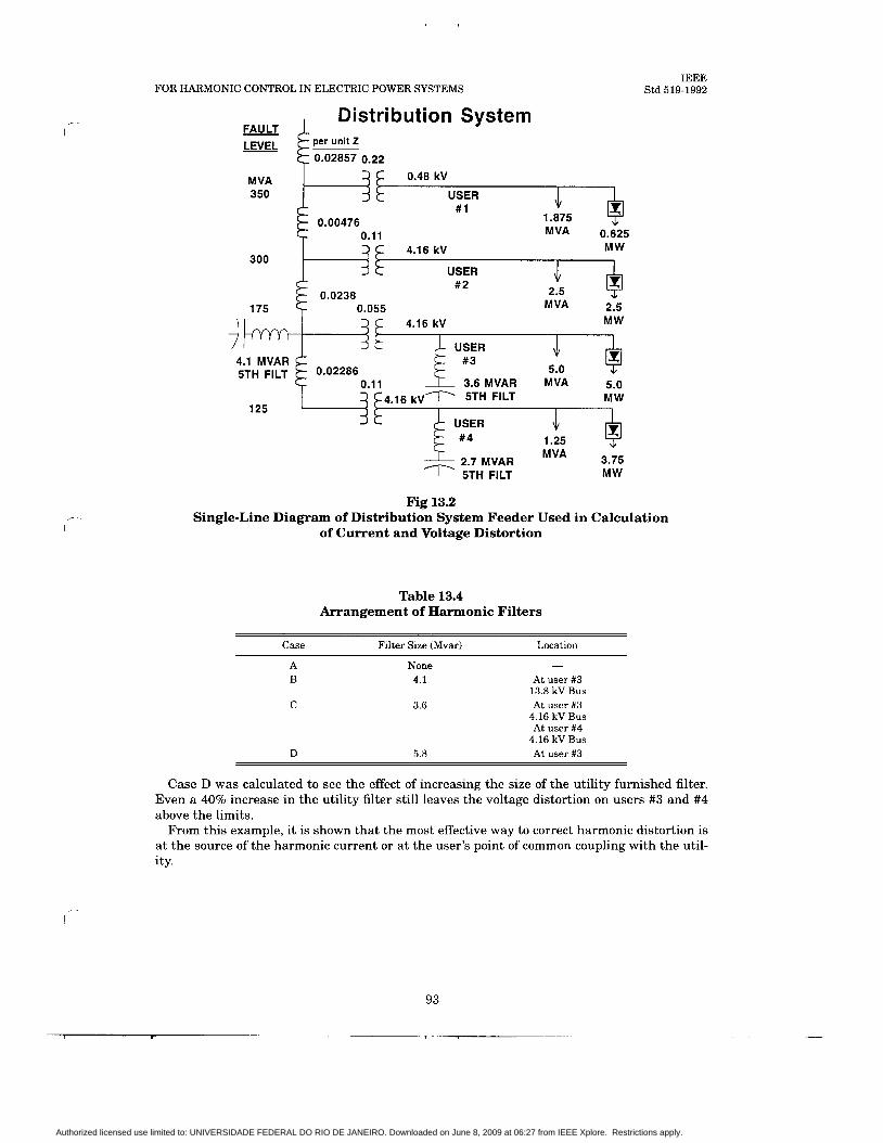
FOR HARMONIC CONTROL IN ELECTRIC POWER SYSTEMS
Distribution System FAULT
0.48 kV
1.875 MVA 0.625
0.00476
4.16 kV MW 300
175
USER #2 .. -
0.0238 0.055 M VA 2.5
2.7 MVAR MVA 3.75 I 5TH FlLT MW
IEEE Std 519-1992
Fig 13.2 Single-Line Diagram of Distribution System Feeder Used in Calculation
of Current and Voltage Distortion
Table 13.4 Arrangement of Harmonic Filters
Filter Size (Mvar) Location Case
A B
C
D
None 4.1
3.6
5.8
At user #3 13.8 kV Bus At user #3
4.16 kV Bus At user #4
4.16 kV Bus At user #3
Case D was calculated to see the effect of increasing the size of the utility furnished filter. Even a 40% increase in the utility filter still leaves the voltage distortion on users #3 and #4 above the limits.
From this example, it is shown that the most effective way to correct harmonic distortion is at the source of the harmonic current or a t the user's point of common coupling with the util- i ty.
93
__.
Authorized licensed use limited to: UNIVERSIDADE FEDERAL DO RIO DE JANEIRO. Downloaded on June 8, 2009 at 06:27 from IEEE Xplore. Restrictions apply.

IEEE Std 519-1992 IEEE RECOMMENDED PRACTICES AND REQUIREMENTS
m
2 d
2
2
2
- U3
- 0
N
0 c?
3
2 U3
2 d
2 W
0 ni
m 2
2 -
* -
m
0 4
m
0 c?
- 01
2
x -
0
N
0 "I d
2 m
2 -
0
0 ?
- 3
2
m 4 0 - t-
2
2 - d
a 9 3 0
W
2 m
0 v!
m 0 t: -
m 3 1
- m "I 3
0
2 a
03
3 4 0
3 @? m 3
3
- m
,+ "I
+ 0
3 a! -
m
m "I
+ m 1 Da
W
m c?
a t - + +
Q)
N "I 0 x
m 2 I
4 ?k +
0
f
s II n
3 2
94
1 1
Authorized licensed use limited to: UNIVERSIDADE FEDERAL DO RIO DE JANEIRO. Downloaded on June 8, 2009 at 06:27 from IEEE Xplore. Restrictions apply.

IEEE Std 519-1992 FOR HARMONIC CONTROL IN ELECTRIC POWER SYSTEMS
3
0
2
2
- m
N z -
0
3 9
U,
2
2 -
N
€3 2 -
e L" 3
2 3
W 1 3
r-
3 9
r(
rl c?
m
3 @?
m N d
m 2
W
2 m T 3
0 x 2 -
*
d x
2 -
m
8 z W
2
* x 2 3
m 2
0 W
II
95
Authorized licensed use limited to: UNIVERSIDADE FEDERAL DO RIO DE JANEIRO. Downloaded on June 8, 2009 at 06:27 from IEEE Xplore. Restrictions apply.

IEEE Std 519-1992 IEEE RECOMMENDED PRACTICES AND REQUIREMENTS
- CO I 3
In
2 * 2 -
* (9 0
c? N
* 2
m ? 3
m 3 m -
m L" 3
- 0 c9 3
I
rl
3 1
0 L" 3
t-
3 ?
0
2
2 -
N CO
2 * x m 2 m
2 3
2
2
2
-
3
-
3
* 2
8 9 N 0
t- I
- m r: m
'4 r- N 2
r(
N
8 * 8
96
I- I
Authorized licensed use limited to: UNIVERSIDADE FEDERAL DO RIO DE JANEIRO. Downloaded on June 8, 2009 at 06:27 from IEEE Xplore. Restrictions apply.

FOR HARMONIC CONTROL IN ELECTRIC POWER SYSTEMS
t-
(D 1
IEEE Std 519-1992
Authorized licensed use limited to: UNIVERSIDADE FEDERAL DO RIO DE JANEIRO. Downloaded on June 8, 2009 at 06:27 from IEEE Xplore. Restrictions apply.
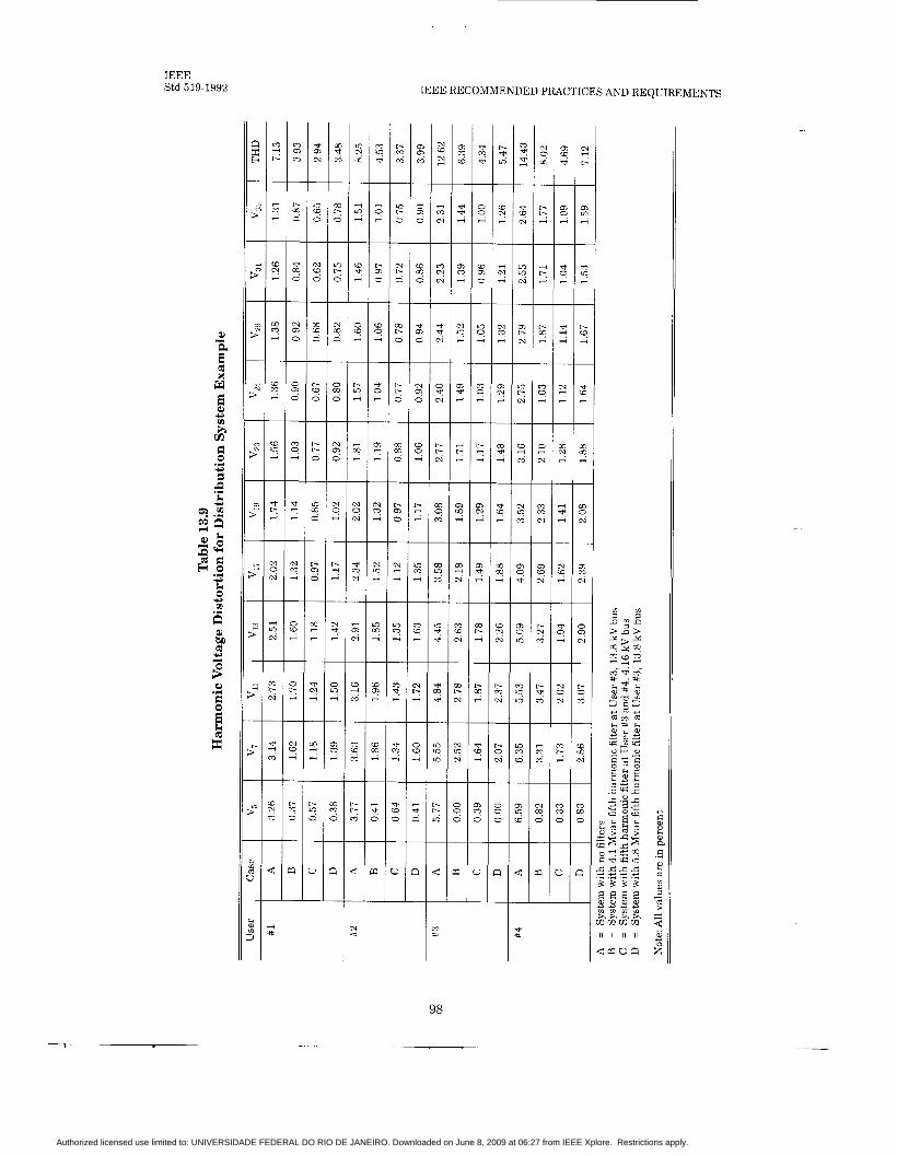
IEEE Std 519-1992 IEEE RECOMMENDED PRACTICES AND REQUIREMENTS
r;. m
0
0 ?
-
W
2 qi N 3
d
r
a r
m U
N
C ir - U 5\:
CI
t-
m 7
0 p: 3
b
N cr
U 9
15 5
L 3 n
m #
98
Authorized licensed use limited to: UNIVERSIDADE FEDERAL DO RIO DE JANEIRO. Downloaded on June 8, 2009 at 06:27 from IEEE Xplore. Restrictions apply.

FOR HARMONIC CONTROL IN ELECTRIC POWER SYSTEMS
14. Bibliography
IEEE Std 519-1992
[Bll IEEE Std 518-1982 (Reaff 1992), IEEE Guide for the Installation of Electrical Equipment to Minimize Noise Inputs to Controllers From External Sources (ANSI).
[B21 Arrillaga, J . , Bradley, D.A., and Bodger, P.S., Power System Harmonics. New York: John Wiley & Sons, Wiley Interscience, 1985.
[B3] Baggot, A. J., “The Effects of Waveshape Distortion on the Measurement of Energy by Tariff Meters,” International Conference on Sources and Effects of Power System Distur- bances, London, England, Apr. 22-24,1974, pp. 261-267.
[B4] Ball, W. C. and Poarch, C. K., “Telephone Influence Factor and Its Measurement,”NEE Transactions on Communications and Electronics, vol. 79, Jan. 1961, pp. 659-664.
[B5] Christensen, E. F., et al., “Analysis of Rectifier Circuits,” AIEE Transactions, vol. 63, 1944, pp. 1048-1058.
[B6] Concordia, C., “Selection of Buffer Reactors and Synchronous Condensers on Power Sys- tems Supplying Arc-Furnace Loads,” AIEE Transactions, vol. 76, pt. 11, July 1957, pp. 123- 135.
[B7] Cummings, P. G., “Estimating Effect of System Harmonics on Losses and Temperature Rise of Squirrel-Cage Motors,” IEEE nansactions on Industry Applications, Nov./Dec. 1986,
r- pp. 1121-1126.
[B8] Douglass, D. A., “Potential Transformer Accuracy a t 60 Hz Voltages Above and Below Rating and a t Frequencies Above 60 Hz,” Paper 80SM 635-3, IEEEPES Summer Meeting, July 1980.
[B9] Downing, W. C., “Watthour Meter Accuracy on SCR Controlled Resistance Loads,” IEEE Transactions on Power Apparatus and Systems, 1974.
[BlO] Faucett, M. A. and Keener, C. A., “Effect of Harmonics on Watthour Meter Accuracy,” Electrical World, Oct. 27, 1945, pp. 82-84.
[Bl l ] Frank, H. and Landstron, Capacitors,” ASEA Journal, vol. 44, 1971, pp. 180-184.
B., “Power Factor Correction with Thyristor-Controlled
[B12] Graham, A. D. and Schonholder, E.T. “Line Harmonics of Converters With DC Motor Loads,” IEEE Transactions on Industry Applications, Jan./Feb. 1983, pp. 84.
[B 131 “Inductive Coordination Aspects of Rectifier Installations,” Committee Report, NEE Transactions, vol. 65, 1946, pp. 417-436.
[B141 Jain, G. C., “The Effect of Voltage Waveshape on the Performance of a Three-phase Induction Motor,” IEEE Dansactions on Power Apparatus and Systems, vol. PAS-84, 1964, pp. 561-566.
-
[B15] Johnson, E. R., “Static High Speed VAR Control for Arc Furnace Flicker Reduction,” Proceedings of the American Power Conference, vol. 34, 1972, pp. 1097-1105.
99
Authorized licensed use limited to: UNIVERSIDADE FEDERAL DO RIO DE JANEIRO. Downloaded on June 8, 2009 at 06:27 from IEEE Xplore. Restrictions apply.

IEEE Std 519-1992
[B161 Jost, F. A., Menzies, D. F., and Sachdev, M. S., “Effect of System Harmonics on Power System Relays,” CEA, System Planning and Operation Section, Power System Protection Committee, Spring Meeting, Mar. 1974.
[B17] Kendall, P. G., “Light Flicker in Relation to Power-System Voltage Fluctuation.” Pro- ceedings of the IEE, vol. 133, 1966, pp. 471-479.
[B181 Kimbark, E. W., Direct Current Dansmission - Vol. I. New York: Wiley-Interscience, 1971, Ch. 8.
[B191 Lembo, F., Jr. and DOnofrio, V. H., “Distribution Harmonics Cause Breaker Problems,” Electrical World, Sep. 1981, pp. 121-122.
[B201 Miller, T. J . E., Reactive Power Control i n Electric Systems. New York: Wiley-Inter- science, Ch. 4, 9, and 10.
[B211 Mulcahy, J. A. and Ludbrook, A., “A New Flicker Correcting System for Arc Furnaces,” Journal of Metals, Apr. 1967, pp. 63-66.
[B22] Oltrogge, A. R., “Fundamental Criteria for Large Arc Furnace Power Systems,’’ Journal of Metals, Jan. 1971, pp. 53-64.
[B23] Pelly, B. R., Thyristor Phase-Controlled Converters and Cycloconverters. New York: John Wiley, 1971.
[B24] Read, J . C., “The Calculation of Rectifier and Converter Performance Characteristics,” Journal of the IEE, vol. 92, pt. 11,1945, pp. 495-509.
[B25] Rice, D. C., “Adjustable Speed Drive and Power Rectifier Harmonics - Their Effect on Power Systems Components,” IEEE paper no. PCIC-84-52, pp. 269-287.
[B26] Shepherd, W., “Steady-state Analysis of the Series Resistance-inductance Circuit Con- trolled by Silicon Controlled Rectifiers,” IEEE Dansactions on Industry Applications, July1 Aug. 1965.
[B271 “Sine Wave Distortions on Power Systems and the Impact on Protective Relaying,” Draft #5, Power System Relay Committee of the PES Report, Nov. 1982.
[B281 “So You Don’t Think You Have a Harmonic Problem,” IEEE Wave Shape Distortion Working Group, Paper presented a t the annual meeting of the IEEE Industry Applications Society, 1979.
[B29] “Survey of Arc-Furnace Installations on Power Systems and Resulting Lamp Flicker,” Subcommittee Report, AIEE Dansactions, vol. 76, pt. 11, Sep. 1957, pp. 170-183.
[B301 “Thyristor-Switched Capacitors Curb Furnace Flicker,” Electrical Review, Aug. 9, 1974, pp. 164-166.
[B3 11 Truxal, J . G., Automatic Feedback Control System Synthesis. New York: McGraw-Hill, 1955, pp. 375-390.
[B321 Wood, W. S., Flynn, F. P., and Poray, A., “Effects of Supply Voltage Waveform Distortion on Motor Performance,” International Conference on Sources and Effects of Power System Disturbances, London, England, Apr. 22-23, 1974, pp. 261-267.
100
Authorized licensed use limited to: UNIVERSIDADE FEDERAL DO RIO DE JANEIRO. Downloaded on June 8, 2009 at 06:27 from IEEE Xplore. Restrictions apply.


![IEEE recommended practice for the electrical design and ... · PDF file[261 ieee std 80-1986, ... and operation of windfarm generating stations ieee m / ) -+- , - :> &] ieee ieee recommended](https://img.pdfslide.us/doc/110x75/5a8d9ca77f8b9adb648ccbfd/ieee-recommended-practice-for-the-electrical-design-and-261-ieee-std-80-1986.jpg)