Embed Size (px)
Citation preview

Symmetrical Components
IEEE PES Boston Chapter
Technical Meeting
September, 19 2017
National Grid, Waltham, MA

IEEE-PES-Boston-2017-Fall Symmetrical Components 2
• History and Description
• The General Method of Symmetrical Components – N-Phase Systems
– 3-Phase Systems
• Circuit Element Sequence Representations
• Fault Analysis Using Symmetrical Components
Symmetrical Components
Discussion Topics
_______________________________________ 1J. Lewis Blackburn and Thomas J. Domin, Protective Relaying Principles and Applications, 3rd Ed., CRC Press, 2007
. 2John, A Horak, Derivation of Symmetrical Component Theory and Symmetrical Component Networks, Georgia Tech
protective Relaying Conference, Atlanta, GA, April 2005, http://www.basler.com/downloads/Symmcomp.pdf
IEEE-PES-Boston-2017-Fall Symmetrical Components 3
Symmetrical Components – History and Description
• The method of symmetrical components provides a tool to study systems with unbalanced phasors.
• Developed by Charles Fortescue in 1913, who presented a paper entitled’ “Method of Symmetrical Co-ordinates Applied to the Solution of Polyphase Networks.”3
• In mathematics terms, a linear transformation4 is a mapping of quantities between two vector spaces, in this case a physical domain (ABC) and a sequence domain (012).
• The method simplifies circuit analysis of a three-phase mutually coupled circuit by transforming it into 3 single phase circuits with no mutual coupling.
_______________________________________
3Fortescue’s paper is available from the University of Waterloo from
http://thunderbox.uwaterloo.ca/~ccanizar/papers/classical/Fortescue.pdf.
4Rowland, Todd and Weisstein, Eric W. "Linear Transformation." From MathWorld—A Wolfram Web
Resource http://mathworld.wolfram.com/LinearTransformation.html
IEEE-PES-Boston-2017-Fall Symmetrical Components 4
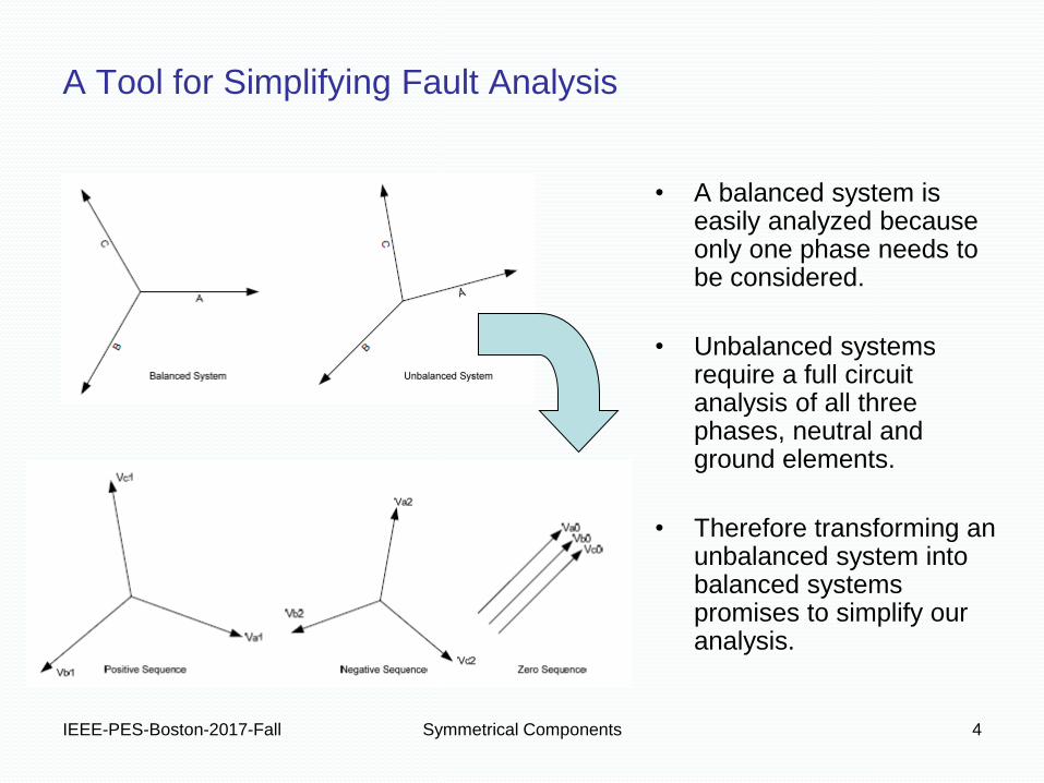
A Tool for Simplifying Fault Analysis
• A balanced system is easily analyzed because only one phase needs to be considered.
• Unbalanced systems require a full circuit analysis of all three phases, neutral and ground elements.
• Therefore transforming an unbalanced system into balanced systems promises to simplify our analysis.
IEEE-PES-Boston-2017-Fall Symmetrical Components 5
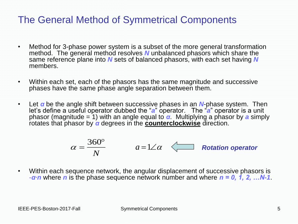
The General Method of Symmetrical Components
• Method for 3-phase power system is a subset of the more general transformation method. The general method resolves N unbalanced phasors which share the same reference plane into N sets of balanced phasors, with each set having N members.
• Within each set, each of the phasors has the same magnitude and successive phases have the same phase angle separation between them.
• Let α be the angle shift between successive phases in an N-phase system. Then let’s define a useful operator dubbed the “a” operator. The “a” operator is a unit phasor (magnitude = 1) with an angle equal to α. Multiplying a phasor by a simply rotates that phasor by α degrees in the counterclockwise direction.
• Within each sequence network, the angular displacement of successive phasors is -α∙n where n is the phase sequence network number and where n = 0, 1, 2, …N-1.
N
360 1a Rotation operator
IEEE-PES-Boston-2017-Fall Symmetrical Components 6
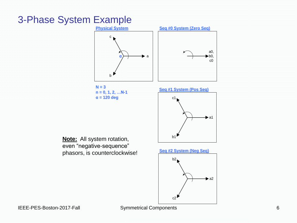
Note: All system rotation,
even “negative-sequence”
phasors, is counterclockwise!
3-Phase System Example Seq #0 System (Zero Seq)Physical System
Seq #1 System (Pos Seq)
Seq #2 System (Neg Seq)
a0,
b0,
c0
a1
b1
c1
a
b
c
a2
c2
b2
N = 3
n = 0, 1, 2, …N-1
α = 120 deg
α
IEEE-PES-Boston-2017-Fall Symmetrical Components 7
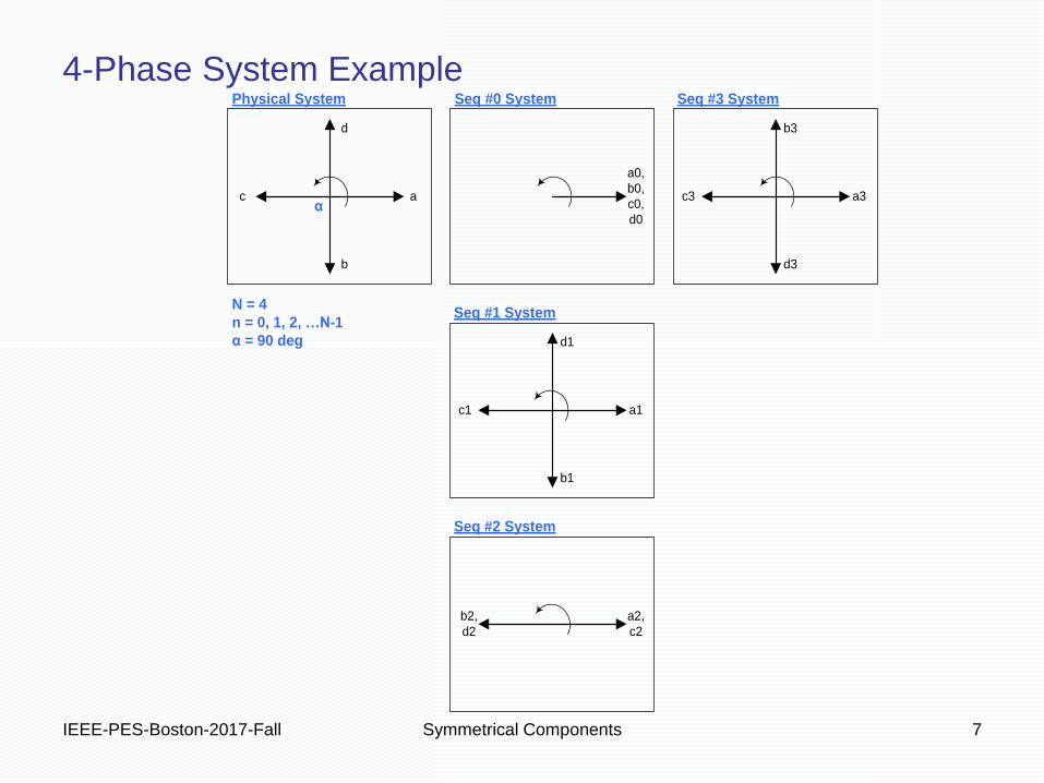
4-Phase System Example Seq #0 SystemPhysical System
Seq #1 System
Seq #2 System
Seq #3 System
a
b
c
d
a1
b1
c1
d1
a2,
c2
b2,
d2
a3
d3
c3
b3
a0,
b0,
c0,
d0
N = 4
n = 0, 1, 2, …N-1
α = 90 deg
α
IEEE-PES-Boston-2017-Fall Symmetrical Components 8
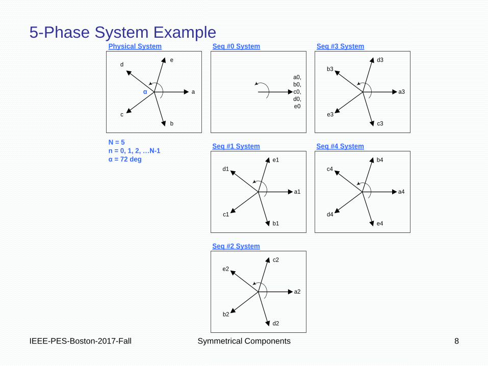
5-Phase System Example Seq #0 System
a0,
b0,
c0,
d0,
e0
Physical System
Seq #1 System
Seq #2 System
Seq #3 System
Seq #4 System
a
b
c
de
a1
b1
c1
d1
e1
a4
e4
d4
c4
b4
a2
d2
b2
e2
c2
a3
c3
e3
b3
d3
N = 5
n = 0, 1, 2, …N-1
α = 72 deg
α
IEEE-PES-Boston-2017-Fall Symmetrical Components 9
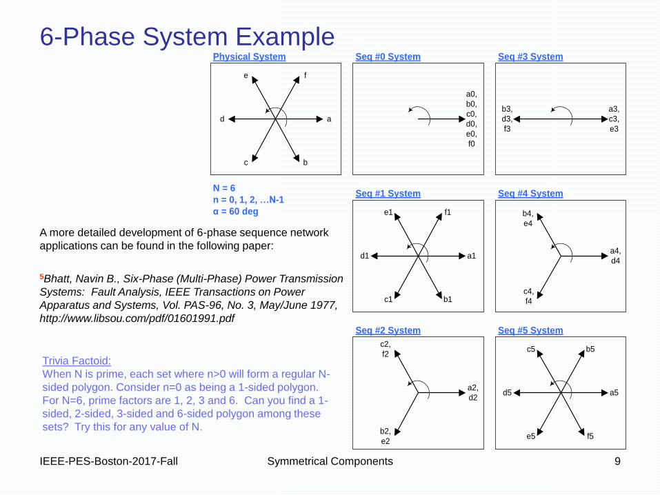
6-Phase System Example
A more detailed development of 6-phase sequence network
applications can be found in the following paper:
5Bhatt, Navin B., Six-Phase (Multi-Phase) Power Transmission
Systems: Fault Analysis, IEEE Transactions on Power
Apparatus and Systems, Vol. PAS-96, No. 3, May/June 1977,
http://www.libsou.com/pdf/01601991.pdf
Trivia Factoid:
When N is prime, each set where n>0 will form a regular N-
sided polygon. Consider n=0 as being a 1-sided polygon.
For N=6, prime factors are 1, 2, 3 and 6. Can you find a 1-
sided, 2-sided, 3-sided and 6-sided polygon among these
sets? Try this for any value of N.
Seq #0 System
a5
f5e5
d5
c5 b5
a2,
d2
b2,
e2
c2,
f2
a1
b1c1
d1
e1 f1
a4,
d4
b4,
e4
c4,
f4
a3,
c3,
e3
b3,
d3,
f3
a0,
b0,
c0,
d0,
e0,
f0
a
bc
d
e f
Physical System
Seq #1 System
Seq #2 System
Seq #3 System
Seq #4 System
Seq #5 System
N = 6
n = 0, 1, 2, …N-1
α = 60 deg
IEEE-PES-Boston-2017-Fall Symmetrical Components 10
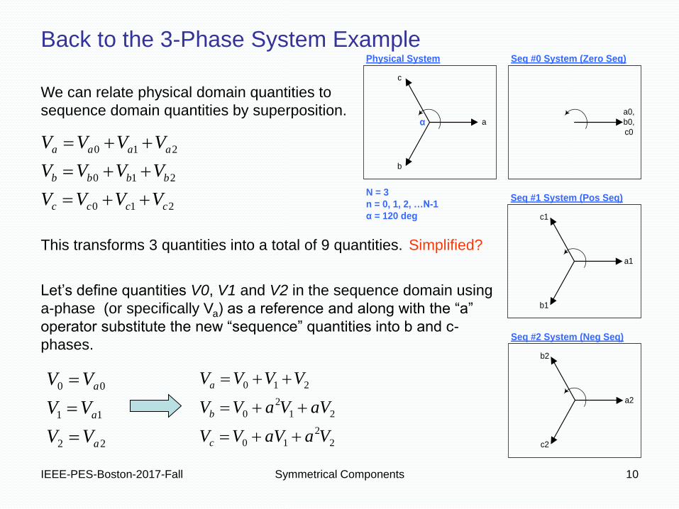
Back to the 3-Phase System Example Seq #0 System (Zero Seq)Physical System
Seq #1 System (Pos Seq)
Seq #2 System (Neg Seq)
a0,
b0,
c0
a1
b1
c1
a
b
c
a2
c2
b2
N = 3
n = 0, 1, 2, …N-1
α = 120 deg
α
210
210
210
cccc
bbbb
aaaa
VVVV
VVVV
VVVV
22
11
00
a
a
a
VV
VV
VV
We can relate physical domain quantities to
sequence domain quantities by superposition.
This transforms 3 quantities into a total of 9 quantities.
2
2
10
21
2
0
210
VaaVVV
aVVaVV
VVVV
c
b
a
Let’s define quantities V0, V1 and V2 in the sequence domain using
a-phase (or specifically Va) as a reference and along with the “a”
operator substitute the new “sequence” quantities into b and c-
phases.
Simplified?

IEEE-PES-Boston-2017-Fall Symmetrical Components 11
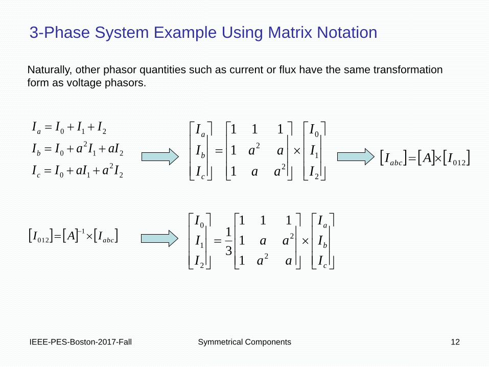
3-Phase System Example Using Matrix Notation
2
2
10
21
2
0
210
VaaVVV
aVVaVV
VVVV
c
b
a
2
1
0
2
2
1
1
111
V
V
V
aa
aa
V
V
V
c
b
a
012VAVabc
Expressing the transformation in matrix notation makes the transformation format easier
to remember.
Matrix notation also lets us easily derive an inverse transform.
abcVAV 1
012
c
b
a
V
V
V
aa
aa
V
V
V
2
2
2
1
0
1
1
111
3
1
IEEE-PES-Boston-2017-Fall Symmetrical Components 12
3-Phase System Example Using Matrix Notation
2
2
10
21
2
0
210
IaaIII
aIIaII
IIII
c
b
a
2
1
0
2
2
1
1
111
I
I
I
aa
aa
I
I
I
c
b
a
012IAIabc
Naturally, other phasor quantities such as current or flux have the same transformation
form as voltage phasors.
abcIAI 1
012
c
b
a
I
I
I
aa
aa
I
I
I
2
2
2
1
0
1
1
111
3
1
IEEE-PES-Boston-2017-Fall Symmetrical Components 13
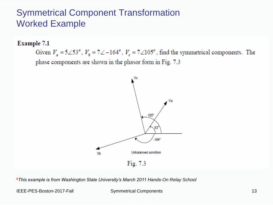
Symmetrical Component Transformation
Worked Example
6This example is from Washington State University’s March 2011 Hands-On Relay School
IEEE-PES-Boston-2017-Fall Symmetrical Components 14
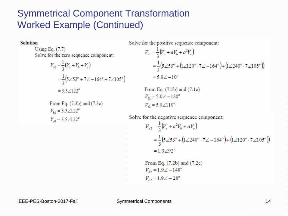
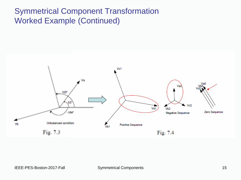
Symmetrical Component Transformation
Worked Example (Continued)
IEEE-PES-Boston-2017-Fall Symmetrical Components 15
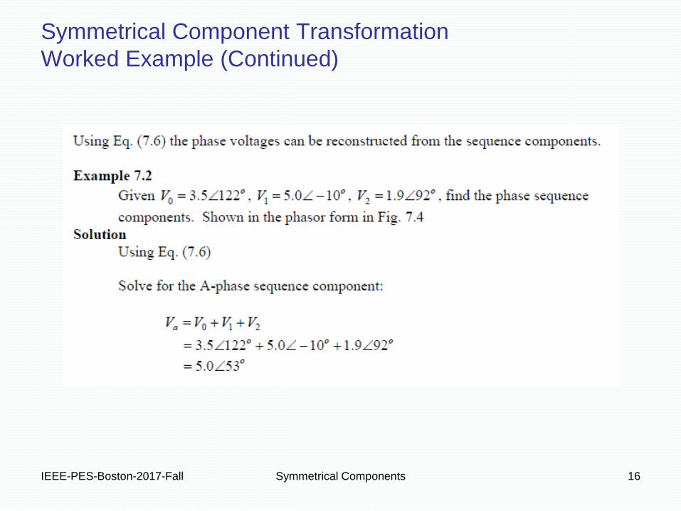
Symmetrical Component Transformation
Worked Example (Continued)
IEEE-PES-Boston-2017-Fall Symmetrical Components 16
Symmetrical Component Transformation
Worked Example (Continued)

IEEE-PES-Boston-2017-Fall Symmetrical Components 17
Symmetrical Component Transformation
Worked Example (Continued)

• 7Steven Blair at the University of Strathclyde has a good interactive
tool for visualizing symmetrical components:
http://personal.strath.ac.uk/steven.m.blair/seq/
IEEE-PES-Boston-2017-Fall Symmetrical Components 18
Symmetrical Component Transformation – Visualization
IEEE-PES-Boston-2017-Fall Symmetrical Components 19
Circuit Element Sequence Representations
IEEE-PES-Boston-2017-Fall Symmetrical Components 20
Circuit Element Sequence Representations
Sequence Networks
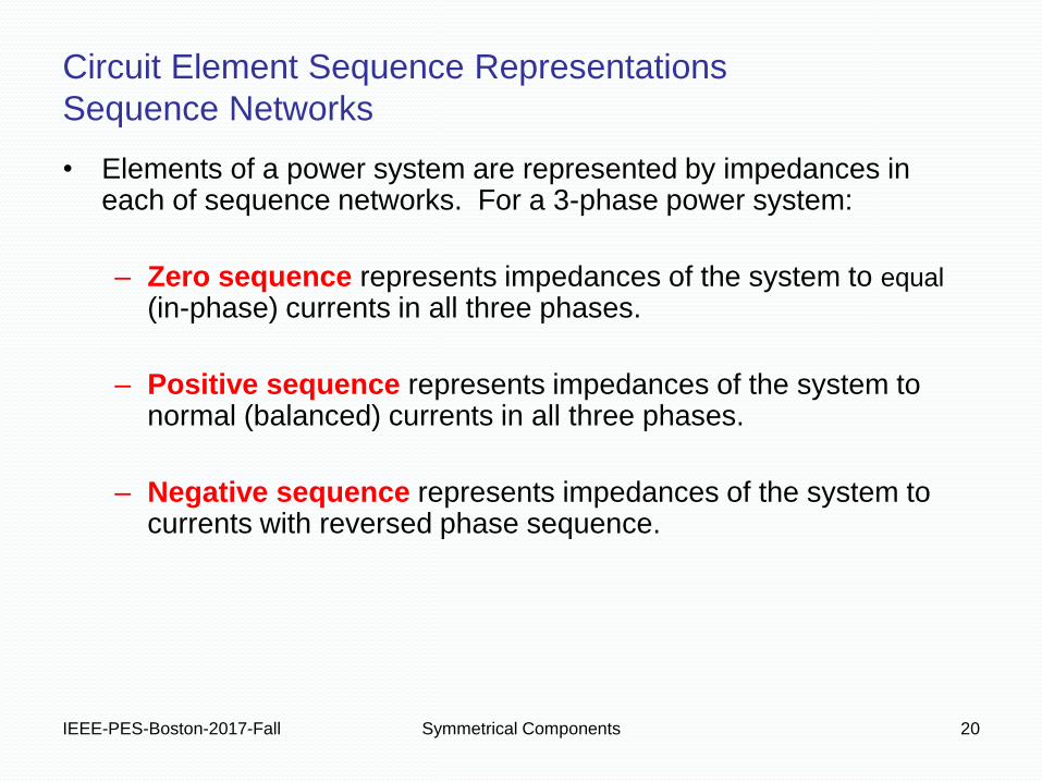
• Elements of a power system are represented by impedances in each of sequence networks. For a 3-phase power system:
– Zero sequence represents impedances of the system to equal (in-phase) currents in all three phases.
– Positive sequence represents impedances of the system to normal (balanced) currents in all three phases.
– Negative sequence represents impedances of the system to currents with reversed phase sequence.
IEEE-PES-Boston-2017-Fall Symmetrical Components 21
Circuit Element Sequence Representations
Sequence Network Independence
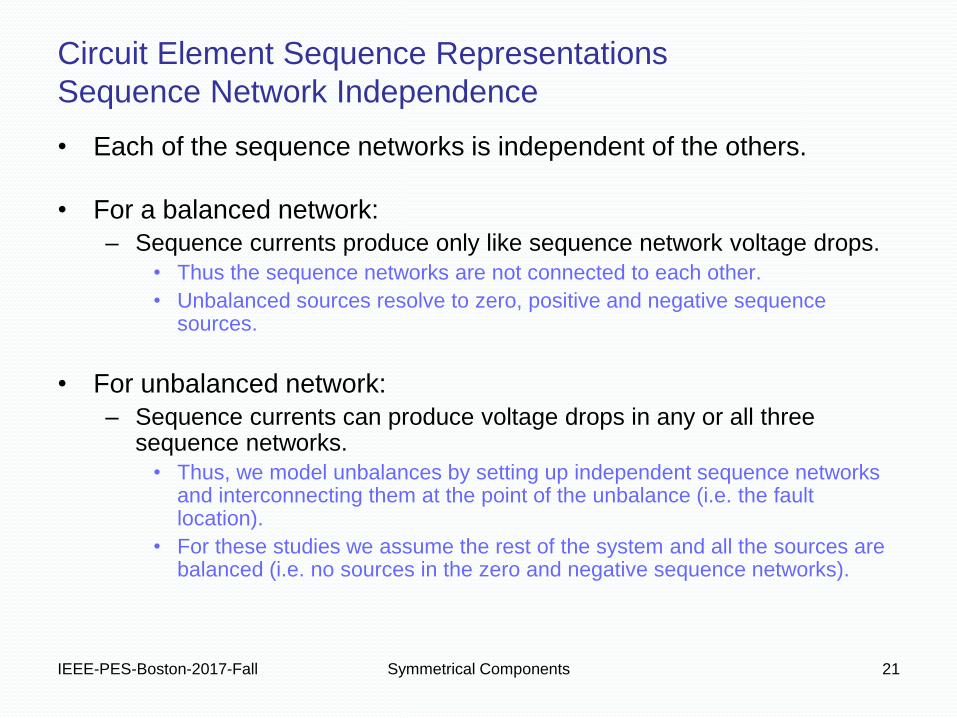
• Each of the sequence networks is independent of the others.
• For a balanced network:
– Sequence currents produce only like sequence network voltage drops.
• Thus the sequence networks are not connected to each other.
• Unbalanced sources resolve to zero, positive and negative sequence sources.
• For unbalanced network:
– Sequence currents can produce voltage drops in any or all three sequence networks.
• Thus, we model unbalances by setting up independent sequence networks and interconnecting them at the point of the unbalance (i.e. the fault location).
• For these studies we assume the rest of the system and all the sources are balanced (i.e. no sources in the zero and negative sequence networks).
IEEE-PES-Boston-2017-Fall Symmetrical Components 22
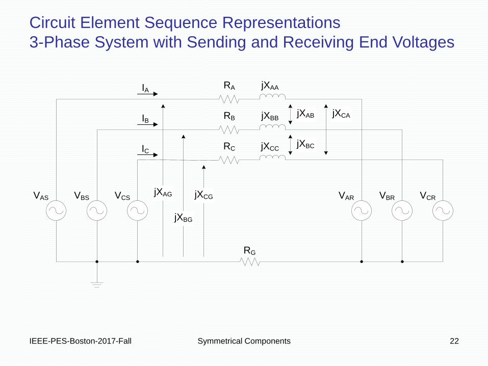
Circuit Element Sequence Representations
3-Phase System with Sending and Receiving End Voltages
RA
RB
RC
jXAA
jXBB
jXCC
RG
VCSVBSVAS VCRVBRVARjXAG jXCG
jXBG
jXAB
jXBC
jXCA
IC
IA
IB
IEEE-PES-Boston-2017-Fall Symmetrical Components 23
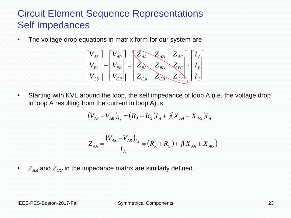
• The voltage drop equations in matrix form for our system are
• Starting with KVL around the loop, the self impedance of loop A (i.e. the voltage drop
in loop A resulting from the current in loop A) is
• ZBB and ZCC in the impedance matrix are similarly defined.
C
B
A
CCCBCA
BCBBBA
ACABAA
CR
BR
AR
CS
BS
AS
I
I
I
ZZZ
ZZZ
ZZZ
V
V
V
V
V
V
AGAAGA
A
IARAS
AA
AAGAAAGAIARAS
XXjRRI
VVZ
IXXjIRRVV
A
A
Circuit Element Sequence Representations
Self Impedances

IEEE-PES-Boston-2017-Fall Symmetrical Components 24
• Again, our voltage drop equations in matrix form are
• The mutual impedance from Loop A to Loop B (i.e. the voltage drop in loop A resulting
from the current in Loop B) is
• The XAG term might look like a typo but recall the following for flux linkage in Phase A:
C
B
A
CCCBCA
BCBBBA
ACABAA
CR
BR
AR
CS
BS
AS
I
I
I
ZZZ
ZZZ
ZZZ
V
V
V
V
V
V
AGABG
B
IARAS
AB XXjRI
VVZ B
)(
)()()()(
)()()()(
)()()()()(
tiLLtiLLtiLLt
titititiwhere
tiLtiLtiLtiLt
CAGACBAGABAAGAAA
CBAG
GAGCACBABAAAA
Circuit Element Sequence Representations
Mutual Impedances

IEEE-PES-Boston-2017-Fall Symmetrical Components 25
• Start with our voltage drop equations in matrix form
• Multiply both sides of the expression by [A-1] which preserves the equality and multiply
[ZABC] by [A-1]·[A] which is the same as multiplying it by the identity matrix [I].
• This leaves us with the voltage drop expressions in the sequence domain.
2
1
0
222120
121110
020100
2
1
0
2
1
0
1111
I
I
I
ZZZ
ZZZ
ZZZ
V
V
V
V
V
V
I
I
I
AA
ZZZ
ZZZ
ZZZ
A
V
V
V
A
V
V
V
A
I
I
I
ZZZ
ZZZ
ZZZ
V
V
V
V
V
V
R
R
R
S
S
S
C
B
A
CCCBCA
BCBBBA
ACABAA
CR
BR
AR
CS
BS
AS
C
B
A
CCCBCA
BCBBBA
ACABAA
CR
BR
AR
CS
BS
AS
Circuit Element Sequence Representations
ABC-to-012 Conversion Using Voltage Drop Expressions
IEEE-PES-Boston-2017-Fall Symmetrical Components 26
2
22
22
1
22
21
0
22
20
2
11
12
1
11
11
0
11
10
2
00
02
1
00
01
0
00
00
2
1
0
222120
121110
020100
2
1
0
2
1
0
210
210
210
)()()(
)()()(
)()()(
I
VVZ
I
VVZ
I
VVZ
I
VVZ
I
VVZ
I
VVZ
I
VVZ
I
VVZ
I
VVZ
I
I
I
ZZZ
ZZZ
ZZZ
V
V
V
V
V
V
IRSIRSIRS
IRSIRSIRS
IRSIRSIRS
R
R
R
S
S
S
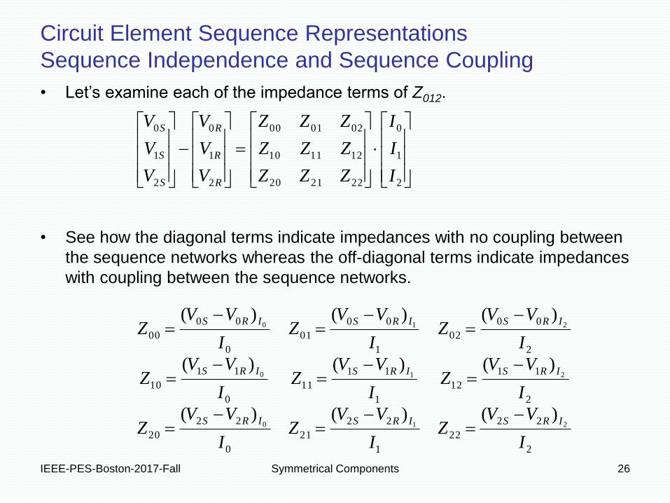
• Let’s examine each of the impedance terms of Z012.
• See how the diagonal terms indicate impedances with no coupling between
the sequence networks whereas the off-diagonal terms indicate impedances
with coupling between the sequence networks.
Circuit Element Sequence Representations
Sequence Independence and Sequence Coupling

IEEE-PES-Boston-2017-Fall Symmetrical Components 27
Cases of Impedance Matrices with High Symmetry
Case 1 – Symmetrical Passive Elements
)(
)(
GMG
ACCBBACABCABM
GSGP
CCBBAAS
CGBGAGG
ACCBBACABCABM
CCBBAAS
CBAP
XXjR
ZZZZZZZ
XXjRR
ZZZZ
XXXX
XXXXXXX
XXXX
RRRR
• In the case of transmission lines, common assumptions include symmetrically spaced
phase conductors with regular conductor transposition. This yields the following
equalities:
• This in turn enables the introduction of new
variables representing self and mutual
impedances.
IEEE-PES-Boston-2017-Fall Symmetrical Components 28
Cases of Impedance Matrices with High Symmetry
Case 1 – Symmetrical Passive Elements
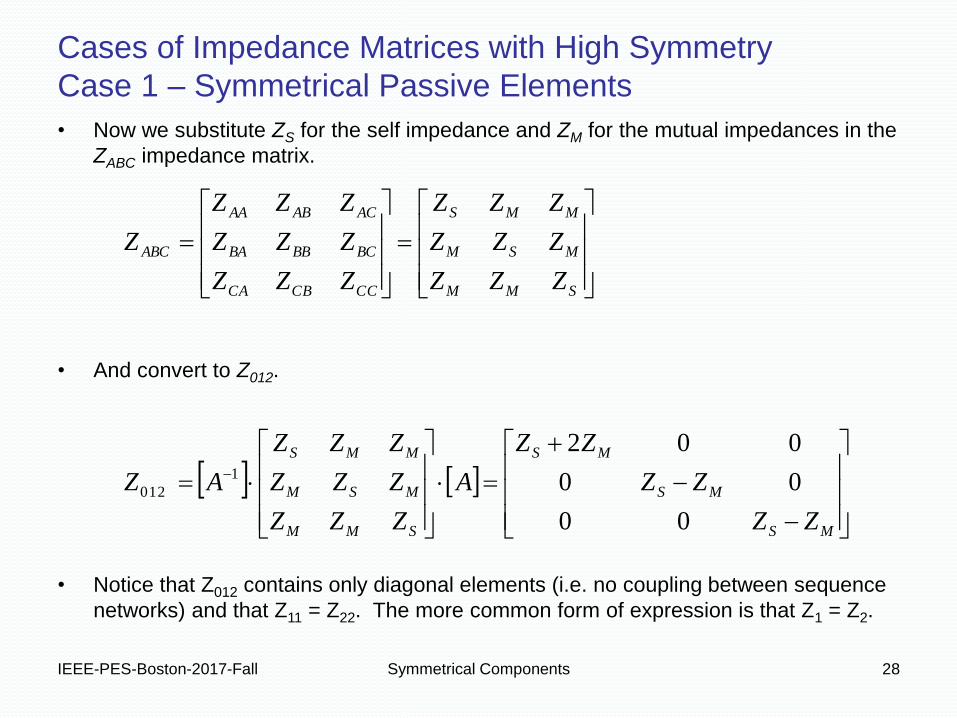
• Now we substitute ZS for the self impedance and ZM for the mutual impedances in the
ZABC impedance matrix.
• And convert to Z012.
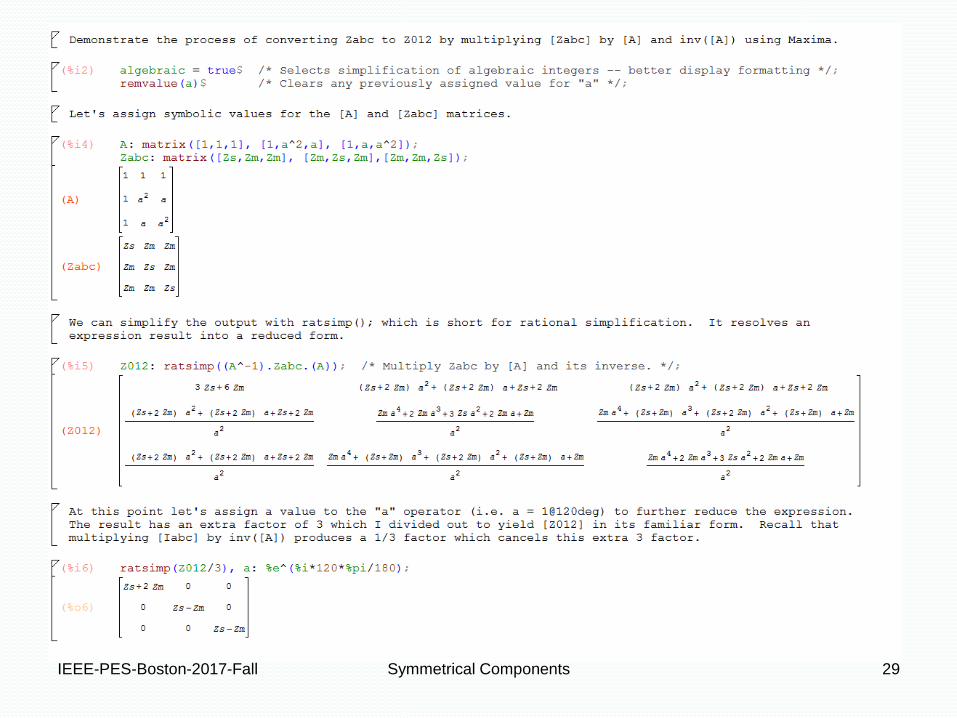
• Notice that Z012 contains only diagonal elements (i.e. no coupling between sequence
networks) and that Z11 = Z22. The more common form of expression is that Z1 = Z2.
MS
MS
MS
SMM
MSM
MMS
SMM
MSM
MMS
CCCBCA
BCBBBA
ACABAA
ABC
ZZ
ZZ
ZZ
A
ZZZ
ZZZ
ZZZ
AZ
ZZZ
ZZZ
ZZZ
ZZZ
ZZZ
ZZZ
Z
00
00
0021
012
IEEE-PES-Boston-2017-Fall Symmetrical Components 29
IEEE-PES-Boston-2017-Fall Symmetrical Components 30
Cases of Impedance Matrices with High Symmetry
Case 2 – Rotating Machines
)()(
)(
GMG
ACCBBAM
GMG
CABCABM
GSGP
CCBBAAS
CGBGAGG
ACCBBAM
CABCABM
CCBBAAS
CBAP
XXjR
ZZZZ
XXjR
ZZZZ
XXjRR
ZZZZ
XXXX
XXXX
XXXX
XXXX
RRRR
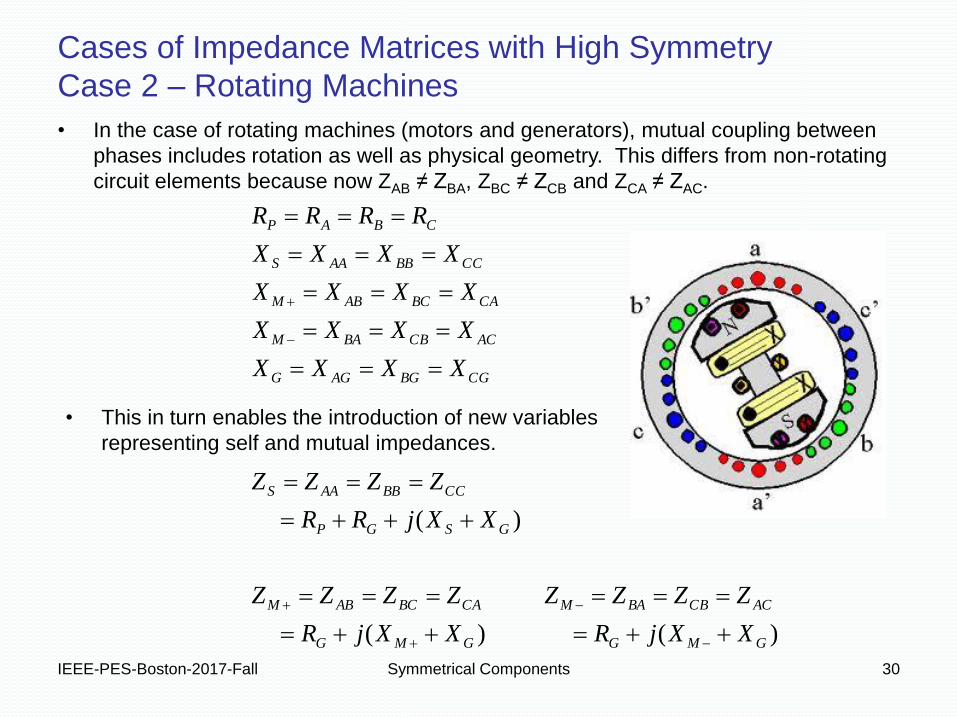
• In the case of rotating machines (motors and generators), mutual coupling between
phases includes rotation as well as physical geometry. This differs from non-rotating
circuit elements because now ZAB ≠ ZBA, ZBC ≠ ZCB and ZCA ≠ ZAC.
• This in turn enables the introduction of new variables
representing self and mutual impedances.
IEEE-PES-Boston-2017-Fall Symmetrical Components 31
Cases of Impedance Matrices with High Symmetry
Case 2 – Rotating Machines
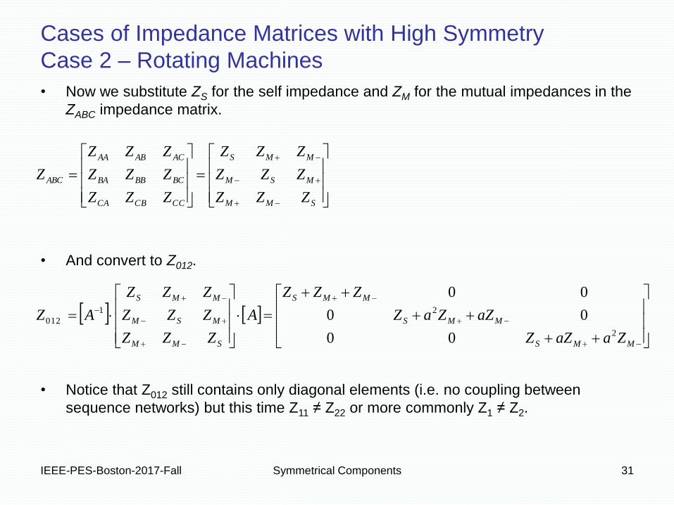
• Now we substitute ZS for the self impedance and ZM for the mutual impedances in the
ZABC impedance matrix.
• And convert to Z012.
• Notice that Z012 still contains only diagonal elements (i.e. no coupling between
sequence networks) but this time Z11 ≠ Z22 or more commonly Z1 ≠ Z2.
MMS
MMS
MMS
SMM
MSM
MMS
SMM
MSM
MMS
CCCBCA
BCBBBA
ACABAA
ABC
ZaaZZ
aZZaZ
ZZZ
A
ZZZ
ZZZ
ZZZ
AZ
ZZZ
ZZZ
ZZZ
ZZZ
ZZZ
ZZZ
Z
2
21
012
00
00
00

IEEE-PES-Boston-2017-Fall Symmetrical Components 32
IEEE-PES-Boston-2017-Fall Symmetrical Components 33
• You can often get Thevenin impedances (Z0 and Z1) directly from short circuit programs like CAPE or Aspen. An equivalent source is nonrotating so Z2 = Z1.
• Otherwise, you can calculate Z0 and Z1 from fault duties, expressed in MVA or kVA based on the system base voltage and the available fault current. You need both 3-phase and SLG fault duties to calculate Z0 (see next slide). With this method assume impedances to be all reactive.
• For hand calculations you can often assume an ideal voltage source, a.k.a. an infinite bus, (i.e. Z0 = Z1 = Z2 = 0).
Circuit Element Sequence Representations
System Equivalent Sources

IEEE-PES-Boston-2017-Fall Symmetrical Components 34
Following is a calculation method for Z0, Z1 and Z2 from given 3ph (S3ph) and SLG (S1ph) fault duties in MVA. Resulting impedances are in per unit.
See Blackburn Appendix 4.1 for a detailed derivation.
Circuit Element Sequence Representations
System Equivalent Sources
ph
Base
S
SZZ
3
21
ph
Base
ph
Base
g
ph
Baseg
S
S
S
S
ZZZZ
ZZZS
SZ
31
210
210
1
23
3
IEEE-PES-Boston-2017-Fall Symmetrical Components 35
Circuit Element Sequence Representations
Synchronous Generators
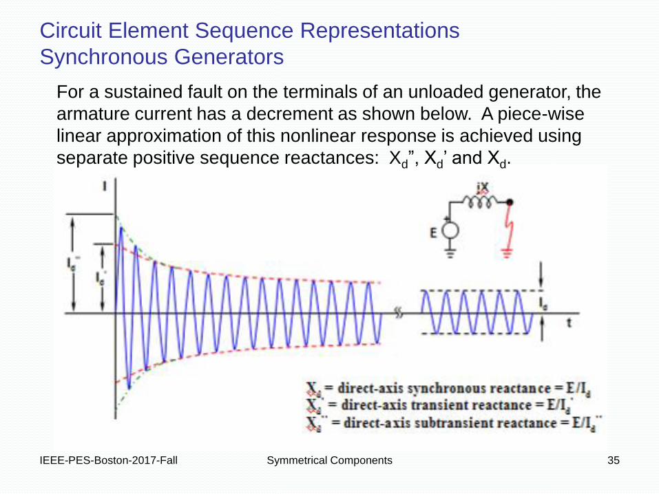
For a sustained fault on the terminals of an unloaded generator, the
armature current has a decrement as shown below. A piece-wise
linear approximation of this nonlinear response is achieved using
separate positive sequence reactances: Xd”, Xd’ and Xd.
IEEE-PES-Boston-2017-Fall Symmetrical Components 36
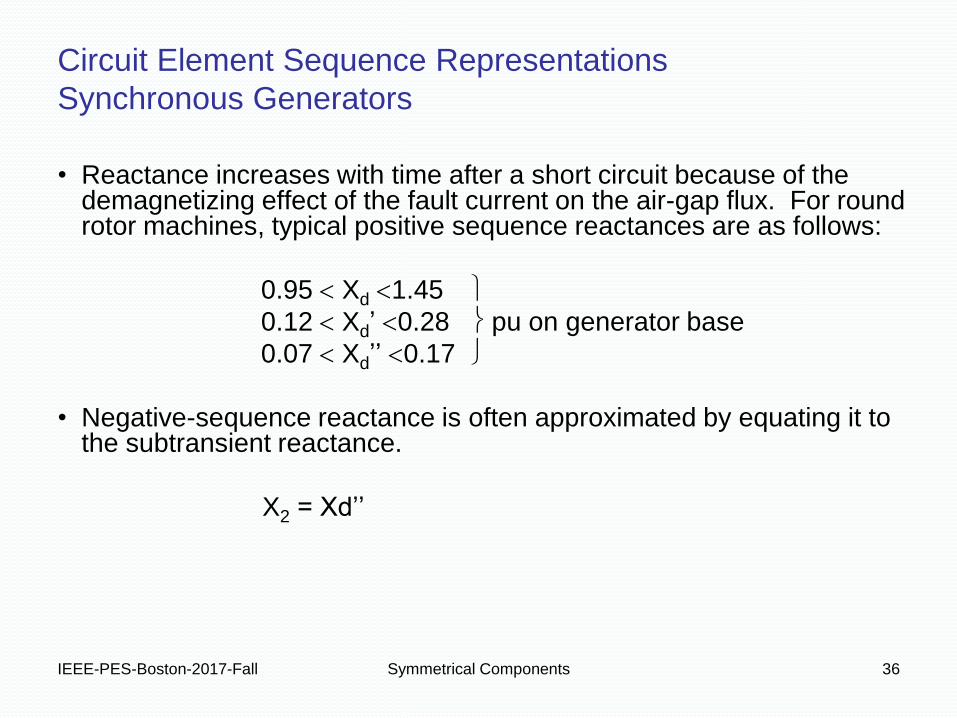
• Reactance increases with time after a short circuit because of the demagnetizing effect of the fault current on the air-gap flux. For round rotor machines, typical positive sequence reactances are as follows:
0.95 Xd 1.45
0.12 Xd’ 0.28 pu on generator base
0.07 Xd’’ 0.17
• Negative-sequence reactance is often approximated by equating it to the subtransient reactance.
X2 = Xd’’
Circuit Element Sequence Representations
Synchronous Generators
IEEE-PES-Boston-2017-Fall Symmetrical Components 37
• Induction machines (motors or generators) are often ignored as fault current sources for relaying purposes.
• The fault current contribution from an induction machine typically decays in a few cycles.
• Induction machine contribution to fault current (subtransient reactance) may be considered when performing maximum instantaneous fault current studies for bus and switchgear rating purposes.
Circuit Element Sequence Representations
Generators – Induction Machines
IEEE-PES-Boston-2017-Fall Symmetrical Components 38
Z0
3Zn Z1
E
Z2
REF REF REF
Pos. Seq. Neg. Seq. Zero Seq.
(Wye-Connected)
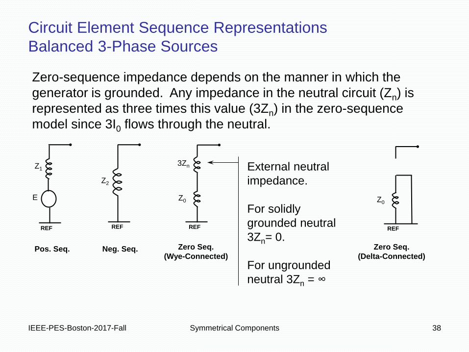
Zero-sequence impedance depends on the manner in which the
generator is grounded. Any impedance in the neutral circuit (Zn) is
represented as three times this value (3Zn) in the zero-sequence
model since 3I0 flows through the neutral.
External neutral
impedance.
For solidly
grounded neutral
3Zn= 0.
For ungrounded
neutral 3Zn = ∞
Circuit Element Sequence Representations
Balanced 3-Phase Sources
Z0
REF
Zero Seq.
(Delta-Connected)

IEEE-PES-Boston-2017-Fall Symmetrical Components 39
• Positive and negative sequence impedances of lumped loads are generally equal. These are shown on a reference phase basis in sequence networks.
• For synchronous motors, particularly those that are designed with salient poles, the negative sequence impedance generally lies between Xd’ and Xd’’.
• Zero sequence impedance of loads depends on the manner in which they are connected and grounded as shown on the following page.
Circuit Element Sequence Representations
Load Impedances
MS
MS
MS
SMM
MSM
MMS
ZZ
ZZ
ZZ
A
ZZZ
ZZZ
ZZZ
AZ
00
00
0021
012
MMS
MMS
MMS
SMM
MSM
MMS
ZaaZZ
aZZaZ
ZZZ
A
ZZZ
ZZZ
ZZZ
AZ2
21
012
00
00
00

IEEE-PES-Boston-2017-Fall Symmetrical Components 40
Z
Z
Z N
Z
Z
Z N
Z
Z
Z N
Z
Z
Z
3I0
Z
REF
Z
REF
Z
3Zn
REF
Z0
REF
3I0
Connection
Arrangement
Zero Sequence
Equivalent Circuits
Circuit Element Sequence Representations
Zero Sequence Models for Different Load Connections
Ia0 = I0
Ib0 = I0
Ic0 = I0
Ia0 = I0
Ib0 = I0
Ic0 = I0
Zn
I0
I0
IEEE-PES-Boston-2017-Fall Symmetrical Components 41
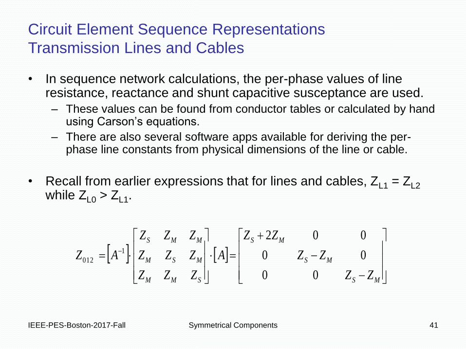
• In sequence network calculations, the per-phase values of line resistance, reactance and shunt capacitive susceptance are used.
– These values can be found from conductor tables or calculated by hand using Carson’s equations.
– There are also several software apps available for deriving the per-phase line constants from physical dimensions of the line or cable.
• Recall from earlier expressions that for lines and cables, ZL1 = ZL2 while ZL0 > ZL1.
Circuit Element Sequence Representations
Transmission Lines and Cables
MS
MS
MS
SMM
MSM
MMS
ZZ
ZZ
ZZ
A
ZZZ
ZZZ
ZZZ
AZ
00
00
0021
012

IEEE-PES-Boston-2017-Fall Symmetrical Components 42
• The zero sequence impedance, ZL0, of an overhead line depends on
several factors which can result in wide variation.
– The use of overhead shield wires and the type of tower grounding and
counterpoise.
– Ground resistivity.
– Zero-sequence impedance is usually 2 to 3.5 times the
positive-sequence impedance.
Circuit Element Sequence Representations
ZL0 for Overhead Transmission Lines
Check out the Z0,
Z1 and Z2 values in
the sample EMTP
line model data.
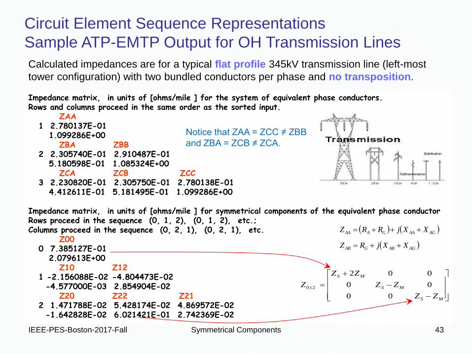
Impedance matrix, in units of [ohms/mile ] for the system of equivalent phase conductors. Rows and columns proceed in the same order as the sorted input. ZAA 1 2.780137E-01 1.099286E+00 ZBA ZBB 2 2.305740E-01 2.910487E-01 5.180598E-01 1.085324E+00 ZCA ZCB ZCC 3 2.230820E-01 2.305750E-01 2.780138E-01 4.412611E-01 5.181495E-01 1.099286E+00 Impedance matrix, in units of [ohms/mile ] for symmetrical components of the equivalent phase conductor Rows proceed in the sequence (0, 1, 2), (0, 1, 2), etc.; Columns proceed in the sequence (0, 2, 1), (0, 2, 1), etc. Z00 0 7.385127E-01 2.079613E+00 Z10 Z12 1 -2.156088E-02 -4.804473E-02 -4.577000E-03 2.854904E-02 Z20 Z22 Z21 2 1.471788E-02 5.428174E-02 4.869572E-02 -1.642828E-02 6.021421E-01 2.742369E-02
IEEE-PES-Boston-2017-Fall Symmetrical Components 43
MS
MS
MS
ZZ
ZZ
ZZ
Z
00
00
002
012
AGAAGAAA XXjRRZ
Circuit Element Sequence Representations
Sample ATP-EMTP Output for OH Transmission Lines
AGABGAB XXjRZ
Calculated impedances are for a typical flat profile 345kV transmission line (left-most
tower configuration) with two bundled conductors per phase and no transposition.
Notice that ZAA = ZCC ≠ ZBB
and ZBA = ZCB ≠ ZCA.
IEEE-PES-Boston-2017-Fall Symmetrical Components 44
• For cables, the type of sheath or pipe used in the construction is a
major factor in the zero-sequence impedance.
• In addition, the placement of the phase conductors relative to each
other affects the amount of current flow in the cable sheaths or pipe
and thus has a significant impact on the zero-sequence impedance.
Circuit Element Sequence Representations
ZL0 for Transmission Line Cables
IEEE-PES-Boston-2017-Fall Symmetrical Components 45
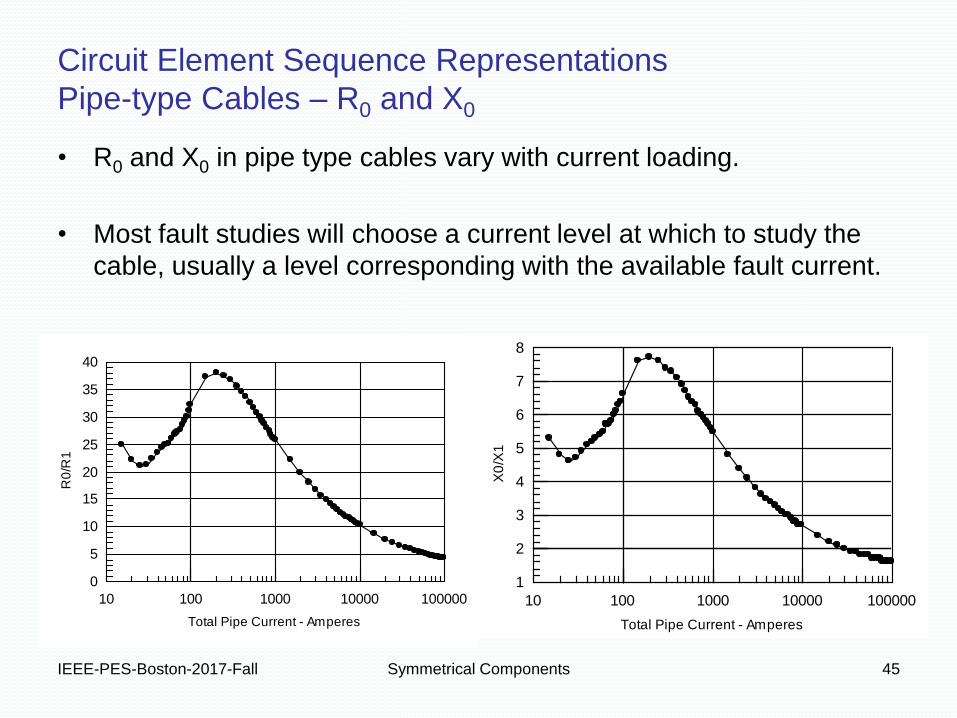
R0
/R1
Total Pipe Current - Amperes
0
5
10
15
20
25
30
35
40
10 100 1000 10000 100000
Circuit Element Sequence Representations
Pipe-type Cables – R0 and X0
X0
/X1
Total Pipe Current - Amperes
1
2
3
4
5
6
7
8
10 100 1000 10000 100000
• R0 and X0 in pipe type cables vary with current loading.
• Most fault studies will choose a current level at which to study the
cable, usually a level corresponding with the available fault current.
IEEE-PES-Boston-2017-Fall Symmetrical Components 46
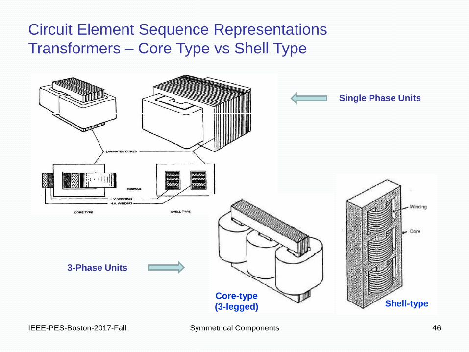
Core-type
(3-legged) Shell-type
Circuit Element Sequence Representations
Transformers – Core Type vs Shell Type
Single Phase Units
3-Phase Units
IEEE-PES-Boston-2017-Fall Symmetrical Components 47
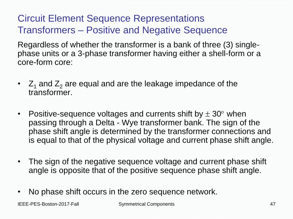
Regardless of whether the transformer is a bank of three (3) single-phase units or a 3-phase transformer having either a shell-form or a core-form core:
• Z1 and Z2 are equal and are the leakage impedance of the transformer.
• Positive-sequence voltages and currents shift by 30 when passing through a Delta - Wye transformer bank. The sign of the phase shift angle is determined by the transformer connections and is equal to that of the physical voltage and current phase shift angle.
• The sign of the negative sequence voltage and current phase shift angle is opposite that of the positive sequence phase shift angle.
• No phase shift occurs in the zero sequence network.
Circuit Element Sequence Representations
Transformers – Positive and Negative Sequence
Core-type
(3-legged)
IEEE-PES-Boston-2017-Fall Symmetrical Components 48
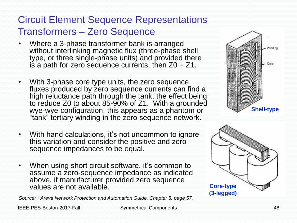
• Where a 3-phase transformer bank is arranged without interlinking magnetic flux (three-phase shell type, or three single-phase units) and provided there is a path for zero sequence currents, then Z0 = Z1.
• With 3-phase core type units, the zero sequence fluxes produced by zero sequence currents can find a high reluctance path through the tank, the effect being to reduce Z0 to about 85-90% of Z1. With a grounded wye-wye configuration, this appears as a phantom or “tank” tertiary winding in the zero sequence network.
• With hand calculations, it’s not uncommon to ignore this variation and consider the positive and zero sequence impedances to be equal.
• When using short circuit software, it’s common to assume a zero-sequence impedance as indicated above, if manufacturer provided zero sequence values are not available.
Circuit Element Sequence Representations
Transformers – Zero Sequence
Shell-type
Source: 8Areva Network Protection and Automation Guide, Chapter 5, page 57.
IEEE-PES-Boston-2017-Fall Symmetrical Components 49
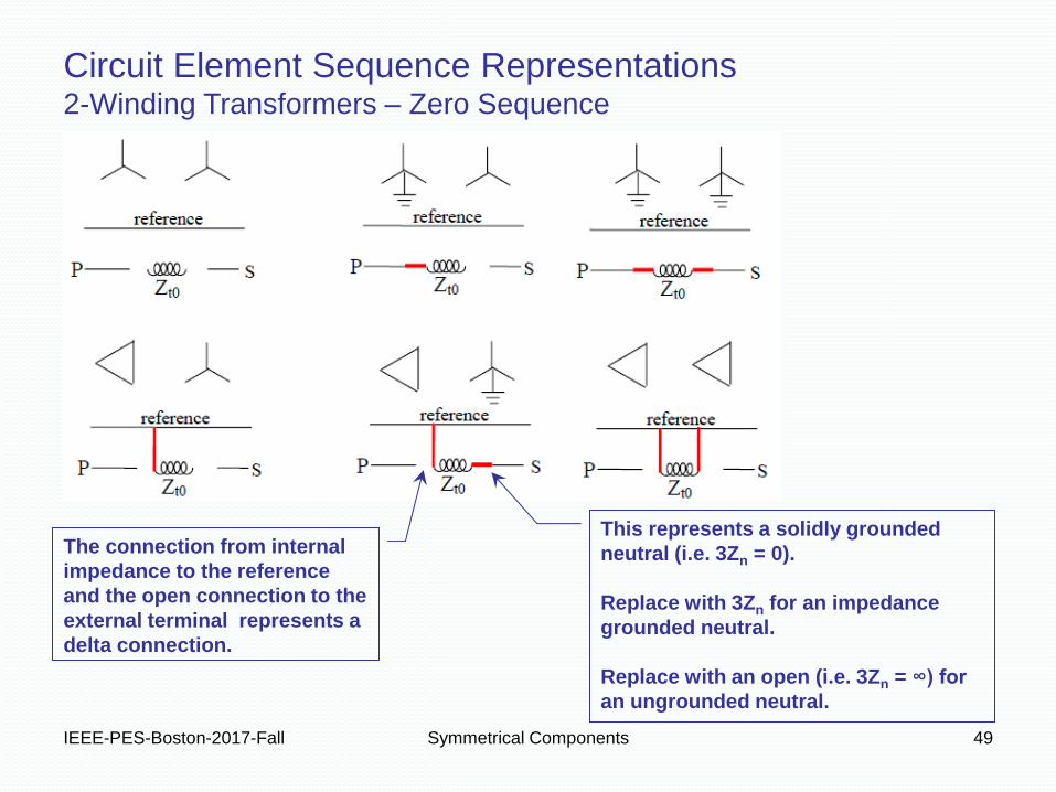
Circuit Element Sequence Representations 2-Winding Transformers – Zero Sequence
This represents a solidly grounded
neutral (i.e. 3Zn = 0).
Replace with 3Zn for an impedance
grounded neutral.
Replace with an open (i.e. 3Zn = ∞) for
an ungrounded neutral.
The connection from internal
impedance to the reference
and the open connection to the
external terminal represents a
delta connection.

IEEE-PES-Boston-2017-Fall Symmetrical Components 50
Circuit Element Sequence Representations
3-Winding and Autotransformers
A 3-winding transformer can be represented with a T-model.
Recall that impedances derived from measurements (i.e test reports) are
those between pairs of windings with the third winding being an open circuit.
Thus we can relate the values ZPS, ZPT and ZST to effective individual winding
impedances ZP, ZS and ZT as follows:
With some algebraic manipulation we can arrive at the following:
IEEE-PES-Boston-2017-Fall Symmetrical Components 51
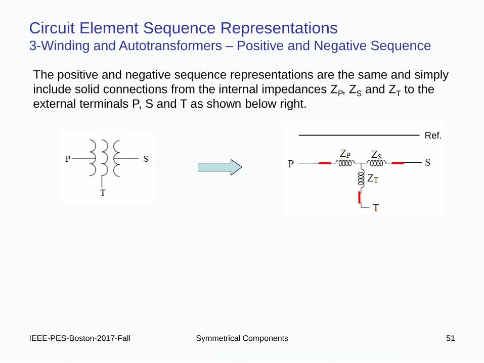
Circuit Element Sequence Representations 3-Winding and Autotransformers – Positive and Negative Sequence
The positive and negative sequence representations are the same and simply
include solid connections from the internal impedances ZP, ZS and ZT to the
external terminals P, S and T as shown below right.
Ref.
IEEE-PES-Boston-2017-Fall Symmetrical Components 52
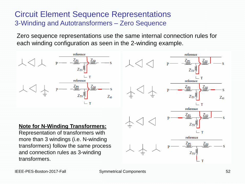
Circuit Element Sequence Representations 3-Winding and Autotransformers – Zero Sequence
Note for N-Winding Transformers:
Representation of transformers with
more than 3 windings (i.e. N-winding
transformers) follow the same process
and connection rules as 3-winding
transformers.
Zero sequence representations use the same internal connection rules for
each winding configuration as seen in the 2-winding example.

• Textbook diagrams often present transformer zero sequence
diagrams in a misleading way.
IEEE-PES-Boston-2017-Fall Symmetrical Components 53
Now For a Word About Textbook Lookup Tables …
• They often put neutral connections
where delta connections go.
• They often depict that which is
physically outside the transformer
as being inside the transformer.
• This can make representing
shared neutrals (or neutral buses)
seem harder than it really is.
You can also refer to Figures A4.2-1 and A4.2-3 in
Blackburn (Reference #1).

IEEE-PES-Boston-2017-Fall Symmetrical Components 54
Now For a Word About Textbook Lookup Tables …
A Common but Incorrect Mapping of I0 to IN
Current across shunt elements in the zero sequence representation corresponds with
neutral current.
If the zero sequence is open, as for a delta-delta transformer or ungrounded wye
winding, clearly there is no neutral current. When there is only a series path there is
zero sequence current flow but not through the neutral.
3I0
3I0 ??!
This is just
wrong.
This is just
wrong.

IEEE-PES-Boston-2017-Fall Symmetrical Components 55
The connection to reference, making Zt0 a shunt element, models the delta connection.
I0 flowing through the shunt connection models I0 inside the delta while I0 leaving Zt0
models I0 in the wye winding.
Consider a similar mapping for wye-wye windings. Notice that when there is only a
series path there is zero sequence current flow through the windings but the net zero
sequence current through the neutrals is zero.
I0
I0
I0
Now For a Word About Textbook Lookup Tables …
The Correct Mapping of I0 to IN

• If remember these simple connection rules for wye grounding and
delta arrangements, you may never need a lookup table again.
• Always draw what’s physically outside the transformer as being
outside the transformer in your sequence representations.
IEEE-PES-Boston-2017-Fall Symmetrical Components 56
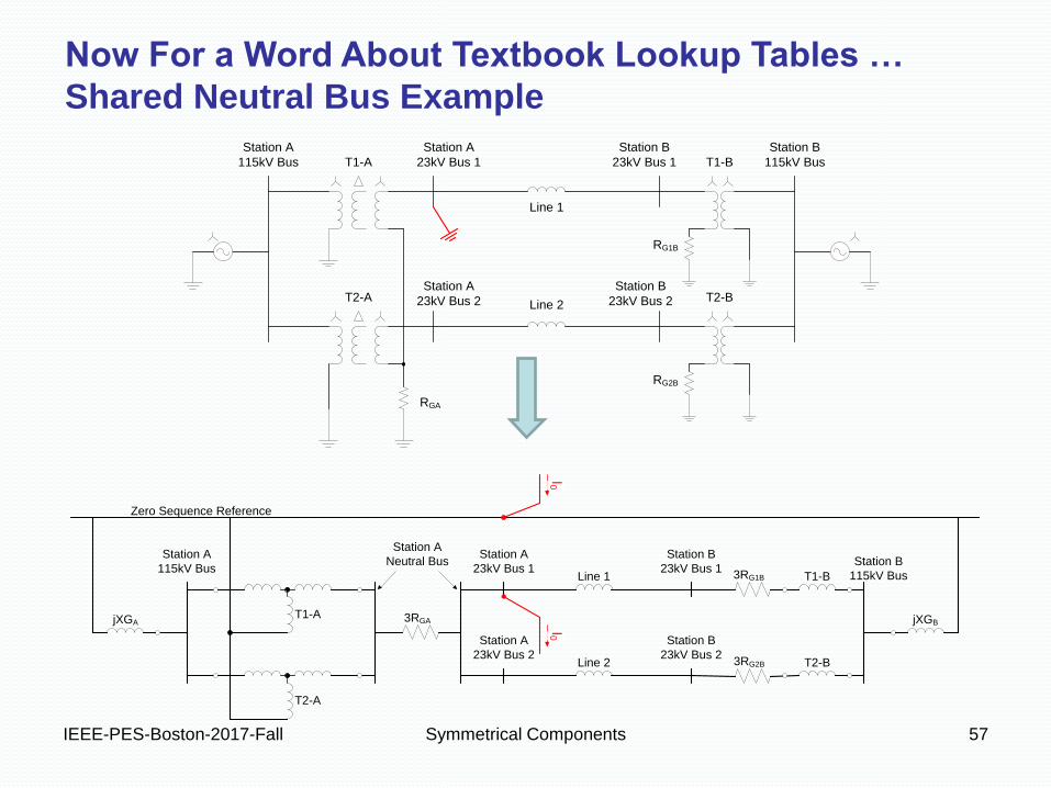
Now For a Word About Textbook Lookup Tables …
Shared Neutral Bus Example
H XT
H0 X0T0
H XT
H0 X0T0
jXH XH jXX
jXX
T
jXH XjXX
jXX
T
3RG
RG
See the problem?
IEEE-PES-Boston-2017-Fall Symmetrical Components 57
T2-A
Station A
115kV Bus T1-A
Station A
23kV Bus 1
Station A
23kV Bus 2 T2-B
T1-B
Station B
23kV Bus 1
Station B
23kV Bus 2
Line 1
Line 2
Station B
115kV Bus
RGA
RG1B
RG2B
Now For a Word About Textbook Lookup Tables …
Shared Neutral Bus Example
T1-AjXGA
T2-A
Station A
23kV Bus 1
Station A
23kV Bus 2
Station A
115kV Bus
3RGA
Zero Sequence Reference
Line 1
Line 2
Station B
23kV Bus 1
Station B
23kV Bus 23RG2B
T1-B
T2-B
Station A
Neutral Bus3RG1B
Station B
115kV Bus
jXGBI0I0
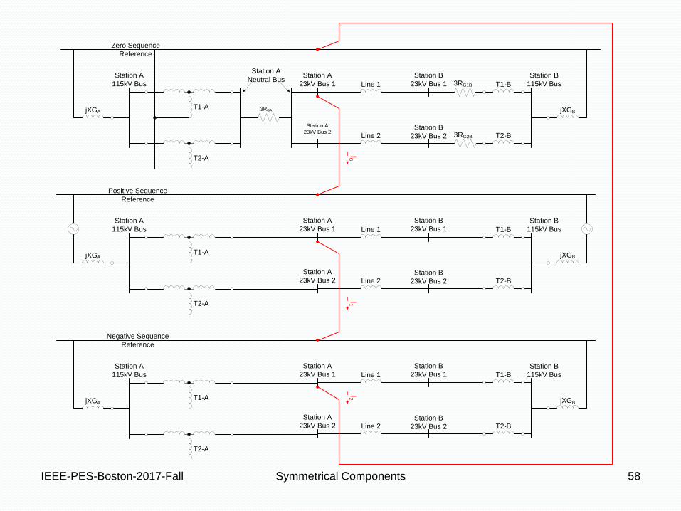
IEEE-PES-Boston-2017-Fall Symmetrical Components 58
T1-AjXGA
T2-A
Station A
23kV Bus 1
Station A
23kV Bus 2
Station A
115kV Bus
3RGA
Zero Sequence
Reference
Line 1
Line 2
Station B
23kV Bus 1
Station B
23kV Bus 2 3RG2B
T1-B
T2-B
Station A
Neutral Bus3RG1B
Station B
115kV Bus
jXGB
T1-A
T2-A
Station A
115kV Bus
jXGA
Positive Sequence
Reference
Station A
23kV Bus 1
Station A
23kV Bus 2
Line 1
Line 2
Station B
23kV Bus 1
Station B
23kV Bus 2
T1-B
T2-B
Station B
115kV Bus
jXGB
T1-A
T2-A
Station A
115kV Bus
jXGA
Negative Sequence
Reference
Station A
23kV Bus 1
Station A
23kV Bus 2
Line 1
Line 2
Station B
23kV Bus 1
Station B
23kV Bus 2
T1-B
T2-B
Station B
115kV Bus
jXGB
I0I1
I2
IEEE-PES-Boston-2017-Fall Symmetrical Components 59
Fault Analysis Using Symmetrical Components
IEEE-PES-Boston-2017-Fall Symmetrical Components 60
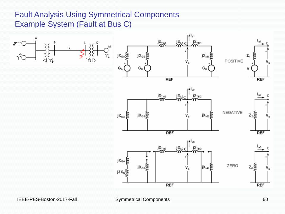
Fault Analysis Using Symmetrical Components
Example System (Fault at Bus C)
IEEE-PES-Boston-2017-Fall Symmetrical Components 61
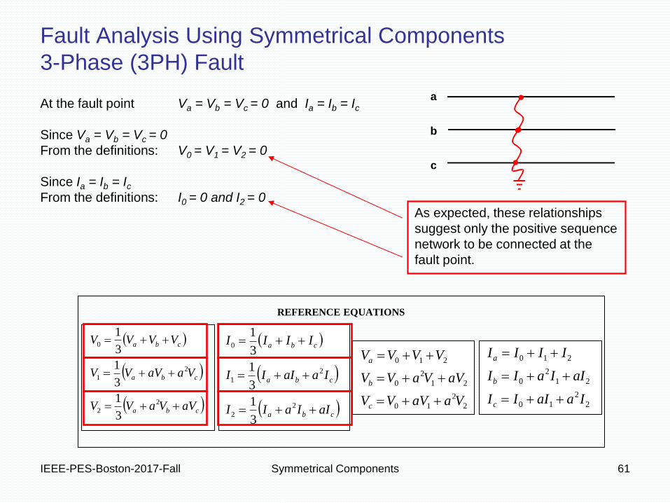
Fault Analysis Using Symmetrical Components
3-Phase (3PH) Fault
At the fault point Va = Vb = Vc = 0 and Ia = Ib = Ic
Since Va = Vb = Vc = 0
From the definitions: V0 = V1 = V2 = 0
Since Ia = Ib = Ic
From the definitions: I0 = 0 and I2 = 0
As expected, these relationships
suggest only the positive sequence
network to be connected at the
fault point.
REFERENCE EQUATIONS
cba
cba
cba
aVVaVV
VaaVVV
VVVV
2
2
2
1
0
3
1
3
1
3
1
cba
cba
cba
aIIaII
IaaIII
IIII
2
2
2
1
0
3
1
3
1
3
1
2
2
10
21
2
0
210
VaaVVV
aVVaVV
VVVV
c
b
a
2
2
10
21
2
0
210
IaaIII
aIIaII
IIII
c
b
a
a
b
c
IEEE-PES-Boston-2017-Fall Symmetrical Components 62
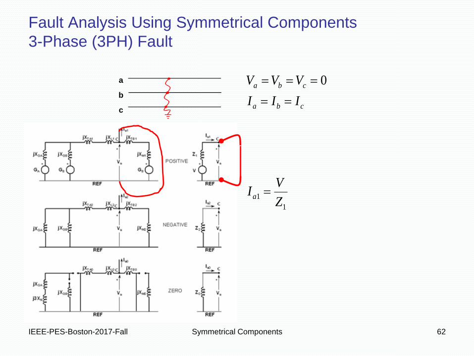
Fault Analysis Using Symmetrical Components
3-Phase (3PH) Fault
1
1
0
Z
VI
III
VVV
a
cba
cba
a
b
c
IEEE-PES-Boston-2017-Fall Symmetrical Components 63
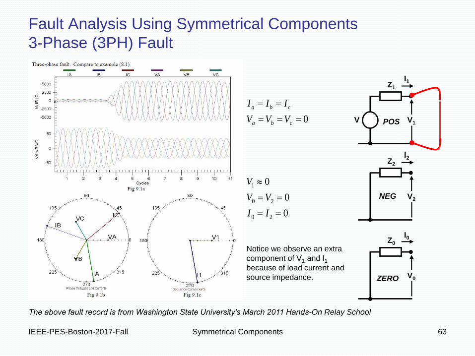
Fault Analysis Using Symmetrical Components
3-Phase (3PH) Fault
Z1
V1 V
I1
Z2
V2
I2
Z0
V0
I0
POS
NEG
ZERO
0
0
0
0
20
20
1
II
VV
V
VVV
III
cba
cba
The above fault record is from Washington State University’s March 2011 Hands-On Relay School
Notice we observe an extra
component of V1 and I1
because of load current and
source impedance.
IEEE-PES-Boston-2017-Fall Symmetrical Components 64
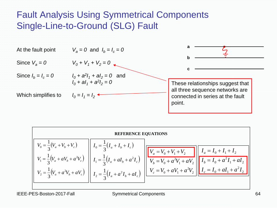
Fault Analysis Using Symmetrical Components
Single-Line-to-Ground (SLG) Fault
a
b
c
REFERENCE EQUATIONS
cba
cba
cba
aVVaVV
VaaVVV
VVVV
2
2
2
1
0
3
1
3
1
3
1
cba
cba
cba
aIIaII
IaaIII
IIII
2
2
2
1
0
3
1
3
1
3
1
2
2
10
21
2
0
210
VaaVVV
aVVaVV
VVVV
c
b
a
2
2
10
21
2
0
210
IaaIII
aIIaII
IIII
c
b
a
At the fault point Va = 0 and Ib = Ic = 0
Since Va = 0 V0 + V1 + V2 = 0
Since Ib = Ic = 0 I0 + a2I1 + aI2 = 0 and
I0 + aI1 + a2I2 = 0
Which simplifies to I0 = I1 = I2
These relationships suggest that
all three sequence networks are
connected in series at the fault
point.
IEEE-PES-Boston-2017-Fall Symmetrical Components 65
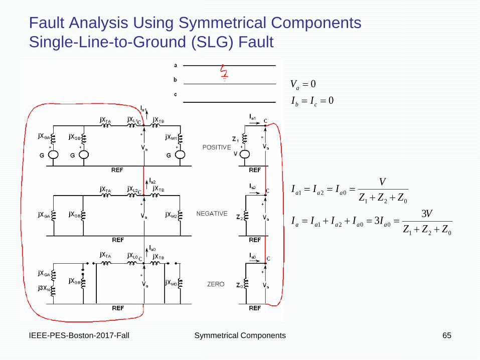
Fault Analysis Using Symmetrical Components
Single-Line-to-Ground (SLG) Fault
021
0021
021
021
33
0
0
ZZZ
VIIIII
ZZZ
VIII
II
V
aaaaa
aaa
cb
a

IEEE-PES-Boston-2017-Fall Symmetrical Components 66
Fault Analysis Using Symmetrical Components
Single-Line-to-Ground (SLG) Fault
210
210 0
0
0
III
VVV
II
V
cb
a
Notice we observe an
extra component of V1
and I1 because of load
current and source
impedance.
I1 Z1
V1 V
Z2
V2
I2
Z0
V0
I0
POS
NEG
ZERO
The above fault record is from Washington State University’s March 2011 Hands-On Relay School
IEEE-PES-Boston-2017-Fall Symmetrical Components 67
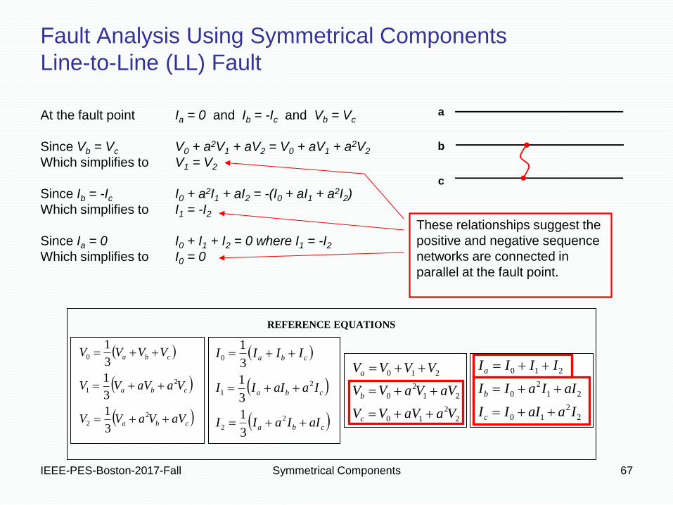
Fault Analysis Using Symmetrical Components
Line-to-Line (LL) Fault
At the fault point Ia = 0 and Ib = -Ic and Vb = Vc
Since Vb = Vc V0 + a2V1 + aV2 = V0 + aV1 + a2V2
Which simplifies to V1 = V2
Since Ib = -Ic I0 + a2I1 + aI2 = -(I0 + aI1 + a2I2)
Which simplifies to I1 = -I2
Since Ia = 0 I0 + I1 + I2 = 0 where I1 = -I2
Which simplifies to I0 = 0
REFERENCE EQUATIONS
cba
cba
cba
aVVaVV
VaaVVV
VVVV
2
2
2
1
0
3
1
3
1
3
1
cba
cba
cba
aIIaII
IaaIII
IIII
2
2
2
1
0
3
1
3
1
3
1
2
2
10
21
2
0
210
VaaVVV
aVVaVV
VVVV
c
b
a
2
2
10
21
2
0
210
IaaIII
aIIaII
IIII
c
b
a
a
b
c
These relationships suggest the
positive and negative sequence
networks are connected in
parallel at the fault point.

IEEE-PES-Boston-2017-Fall Symmetrical Components 68
Fault Analysis Using Symmetrical Components
Line-to-Line (LL) Fault
21
21
21
0
aa
aa
cb
cb
a
VV
ZZ
VII
VV
II
I
IEEE-PES-Boston-2017-Fall Symmetrical Components 69
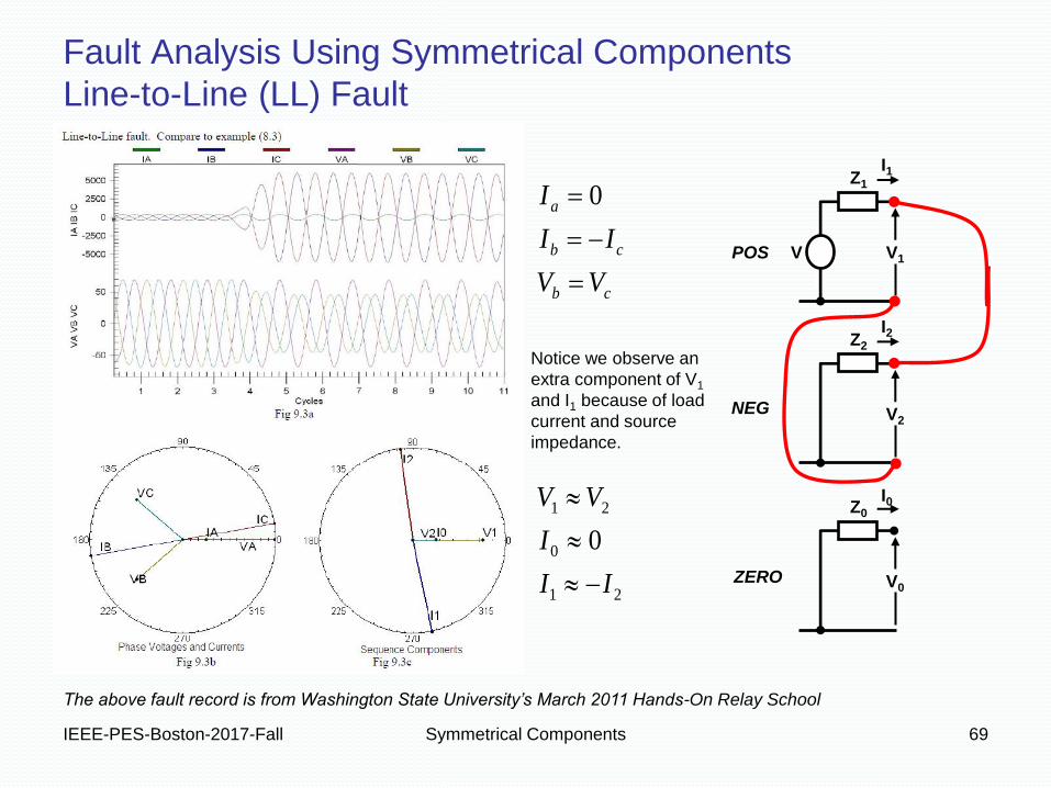
Fault Analysis Using Symmetrical Components
Line-to-Line (LL) Fault
21
0
21
0
0
II
I
VV
VV
II
I
cb
cb
a
Z1
V1 V
I1
Z2
V2
I2
Z0
V0
I0
POS
NEG
ZERO
The above fault record is from Washington State University’s March 2011 Hands-On Relay School
Notice we observe an
extra component of V1
and I1 because of load
current and source
impedance.
IEEE-PES-Boston-2017-Fall Symmetrical Components 70
Fault Analysis Using Symmetrical Components
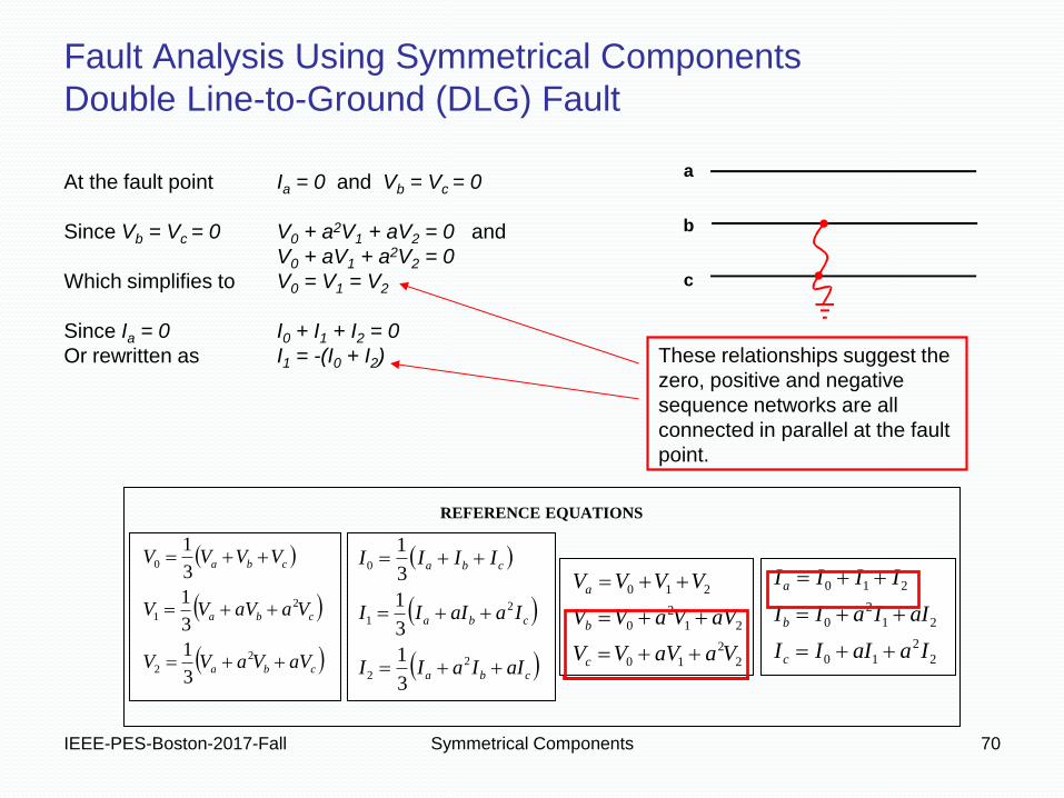
Double Line-to-Ground (DLG) Fault
At the fault point Ia = 0 and Vb = Vc = 0
Since Vb = Vc = 0 V0 + a2V1 + aV2 = 0 and
V0 + aV1 + a2V2 = 0
Which simplifies to V0 = V1 = V2
Since Ia = 0 I0 + I1 + I2 = 0
Or rewritten as I1 = -(I0 + I2) These relationships suggest the
zero, positive and negative
sequence networks are all
connected in parallel at the fault
point.
REFERENCE EQUATIONS
cba
cba
cba
aVVaVV
VaaVVV
VVVV
2
2
2
1
0
3
1
3
1
3
1
cba
cba
cba
aIIaII
IaaIII
IIII
2
2
2
1
0
3
1
3
1
3
1
2
2
10
21
2
0
210
VaaVVV
aVVaVV
VVVV
c
b
a
2
2
10
21
2
0
210
IaaIII
aIIaII
IIII
c
b
a
a
b
c
IEEE-PES-Boston-2017-Fall Symmetrical Components 71
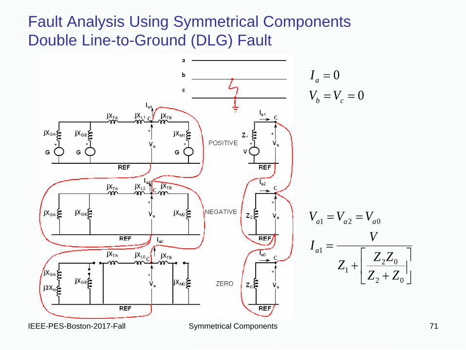
Fault Analysis Using Symmetrical Components
Double Line-to-Ground (DLG) Fault
21
21
21
0
aa
aa
cb
cb
a
VV
ZZ
VII
VV
II
I
02
021
1
021
0
0
ZZ
ZZZ
VI
VVV
VV
I
a
aaa
cb
a
IEEE-PES-Boston-2017-Fall Symmetrical Components 72
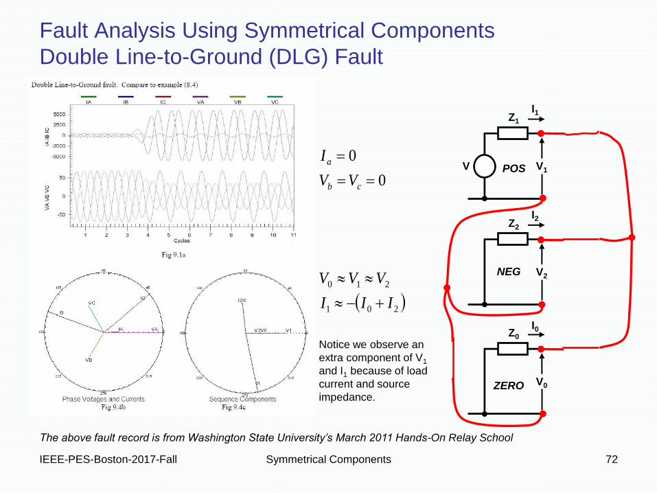
Fault Analysis Using Symmetrical Components
Double Line-to-Ground (DLG) Fault
Z1
V1 V
I1
Z2
V2
I2
Z0
V0
I0
POS
NEG
ZERO
201
210
0
0
III
VVV
VV
I
cb
a
The above fault record is from Washington State University’s March 2011 Hands-On Relay School
Notice we observe an
extra component of V1
and I1 because of load
current and source
impedance.
IEEE-PES-Boston-2017-Fall Symmetrical Components 73
Fault Analysis Using Symmetrical Components
Phase Shifting Across Delta-Wye Transformers

IEEE-PES-Boston-2017-Fall Symmetrical Components 74
Fault Analysis Using Symmetrical Components
Phase Shifting Across Delta-Wye Transformers
For this example HV leads LV by 30°. Let the system
voltage ratio (N) equal 1. Consequently, the turns
ratio (n) must be 1/3. We know that
Because the sequence networks are independent, we
can apply them individually adding the results by
superposition.
Starting with positive sequence values we get the
following for voltage and current.
Pictures and equations are from Appendix 4.3 in Blackburn.
IEEE-PES-Boston-2017-Fall Symmetrical Components 75
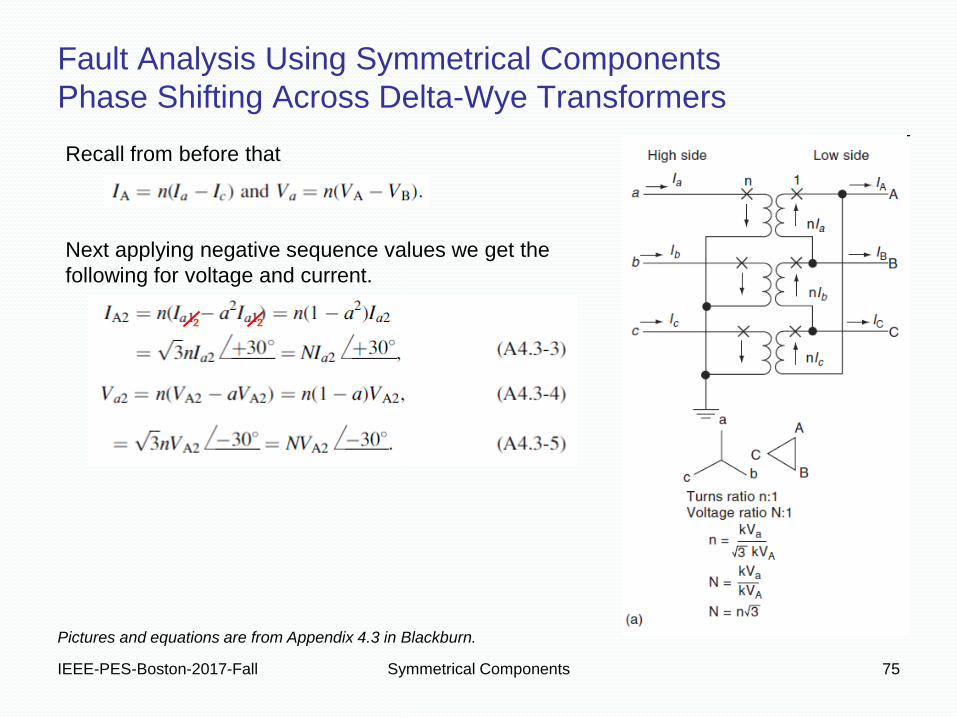
Fault Analysis Using Symmetrical Components
Phase Shifting Across Delta-Wye Transformers
Next applying negative sequence values we get the
following for voltage and current.
Recall from before that
Pictures and equations are from Appendix 4.3 in Blackburn.
2 2
IEEE-PES-Boston-2017-Fall Symmetrical Components 76
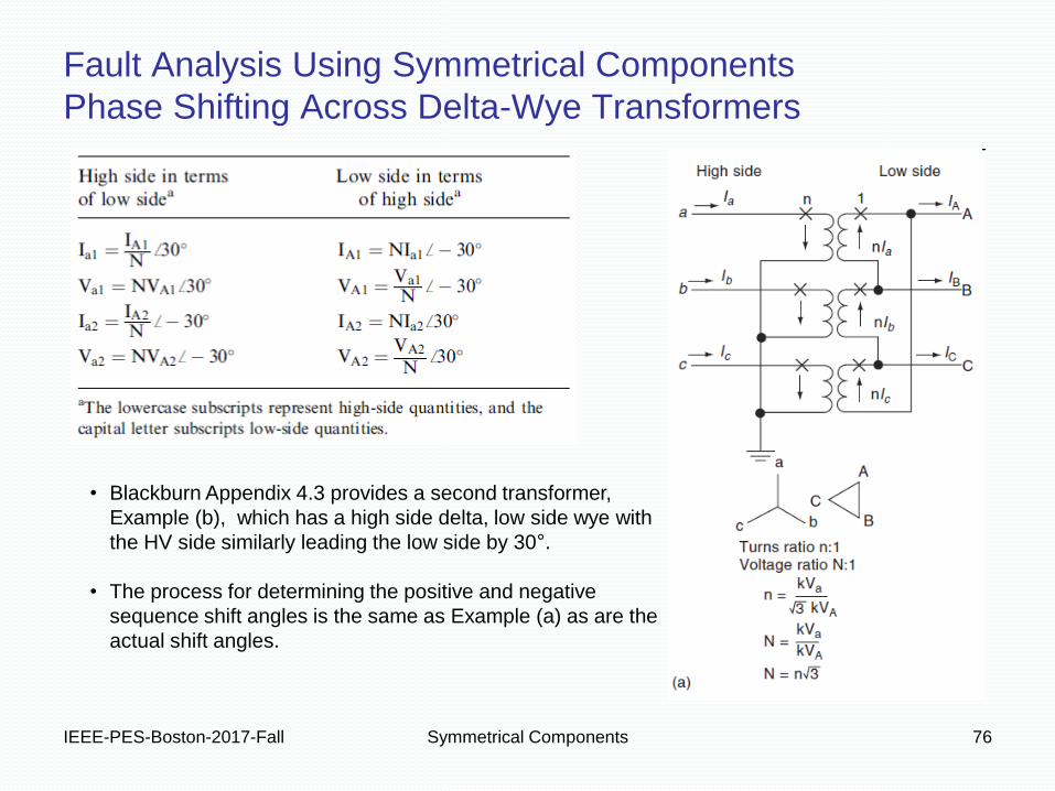
Fault Analysis Using Symmetrical Components
Phase Shifting Across Delta-Wye Transformers
• Blackburn Appendix 4.3 provides a second transformer,
Example (b), which has a high side delta, low side wye with
the HV side similarly leading the low side by 30°.
• The process for determining the positive and negative
sequence shift angles is the same as Example (a) as are the
actual shift angles.
IEEE-PES-Boston-2017-Fall Symmetrical Components 77
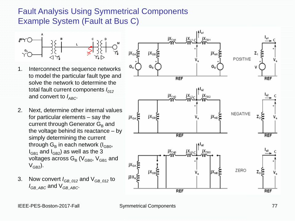
Fault Analysis Using Symmetrical Components
Example System (Fault at Bus C)
1. Interconnect the sequence networks
to model the particular fault type and
solve the network to determine the
total fault current components I012
and convert to IABC.
2. Next, determine other internal values
for particular elements – say the
current through Generator GB and
the voltage behind its reactance – by
simply determining the current
through GB in each network (IGB0,
IGB1 and IGB2) as well as the 3
voltages across GB (VGB0, VGB1 and
VGB2).
3. Now convert IGB_012 and VGB_012 to
IGB_ABC and VGB_ABC.
IEEE-PES-Boston-2017-Fall Symmetrical Components 78
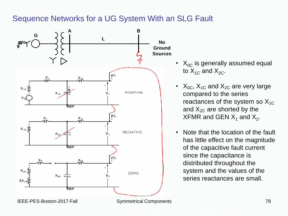
A B
No
Ground
Sources
G L
• X0C is generally assumed equal
to X1C and X2C.
• X0C, X1C and X2C are very large
compared to the series
reactances of the system so X1C
and X2C are shorted by the
XFMR and GEN X1 and X2.
• Note that the location of the fault
has little effect on the magnitude
of the capacitive fault current
since the capacitance is
distributed throughout the
system and the values of the
series reactances are small.
Sequence Networks for a UG System With an SLG Fault
IEEE-PES-Boston-2017-Fall Symmetrical Components 79

IEEE-PES-Boston-2017-Fall Symmetrical Components 80
This is simply not suitable on 3PH-4W (grounded) systems
Common Question From Projects Regarding
Open Delta VTs versus Wye-Wye VTs
Why do I have to reject proposals to use two (2) VTs in an open delta configuration instead
of three (3) VTs in a wye-wye configuration?
9Refer to IEEE Std. C37.230-2007, Guide for Protective Relay Applications to Distribution Lines, Figure 6-5.
IEEE-PES-Boston-2017-Fall Symmetrical Components 81 81
Questions?