Embed Size (px)
Citation preview
May 2, 2016 Document 15-16-0189-01-007a
Submission Page 1 Hsin-Mu Tsai, National Taiwan University
IEEE P802.15 Wireless Personal Area Networks
Project IEEE P802.15 Working Group for Wireless Personal Area Networks (WPANs)
Title Rolling Shutter – Frequency Shift Keying, Input for 802.15.7r1 Draft D0
Date Submitted
[2 May, 2016]
Source [Hsin-Mu (Michael) Tsai (NTU), Yen-Ting Liu (NTU), Yu-Lin Wei (NTU), Kate Ching-Ju Lin (Academia Sinica)] [No. 1, Sec. 4, Roosevelt Rd., Taipei 10617, Taiwan]
Voice: [+886 2 3366-4888] Fax: [ ] E-mail: [[email protected]]
Re:
Abstract [This is the rolling shutter – frequency shift keying input to the 802.15.7r1 draft, prepared by the team at National Taiwan University.]
Purpose [To provide text input for draft D0.]
Notice This document has been prepared to assist the IEEE P802.15. It is offered as a basis for discussion and is not binding on the contributing individual(s) or organization(s). The material in this document is subject to change in form and content after further study. The contributor(s) reserve(s) the right to add, amend or withdraw material contained herein.
Release The contributor acknowledges and accepts that this contribution becomes the property of IEEE and may be made publicly available by P802.15.
May 2, 2016 Document 15-16-0189-01-007a
Submission Page 2 Hsin-Mu Tsai, National Taiwan University
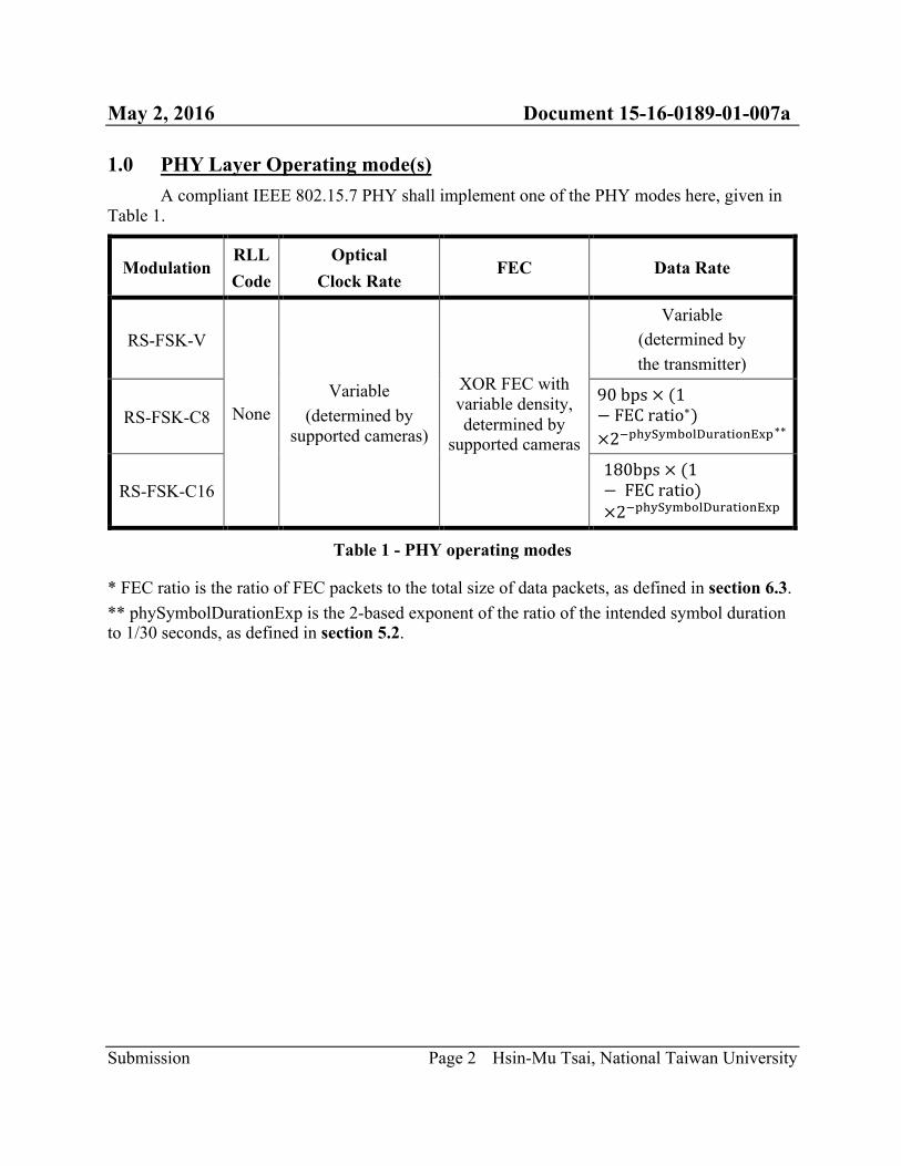
1.0 PHY Layer Operating mode(s) A compliant IEEE 802.15.7 PHY shall implement one of the PHY modes here, given in
Table 1.
Modulation RLL Code
Optical Clock Rate
FEC Data Rate
RS-FSK-V
None Variable
(determined by supported cameras)
XOR FEC with variable density, determined by
supported cameras
Variable (determined by the transmitter)
RS-FSK-C8 90bps×(1− FECratio∗)×26789:9;<=>?@ABCD=EFG7∗∗
RS-FSK-C16 180bps×(1− FECratio)×26789:9;<=>?@ABCD=EFG7
Table 1 - PHY operating modes
* FEC ratio is the ratio of FEC packets to the total size of data packets, as defined in section 6.3. ** phySymbolDurationExp is the 2-based exponent of the ratio of the intended symbol duration to 1/30 seconds, as defined in section 5.2.
May 2, 2016 Document 15-16-0189-01-007a
Submission Page 3 Hsin-Mu Tsai, National Taiwan University
2.0 PHY specifications
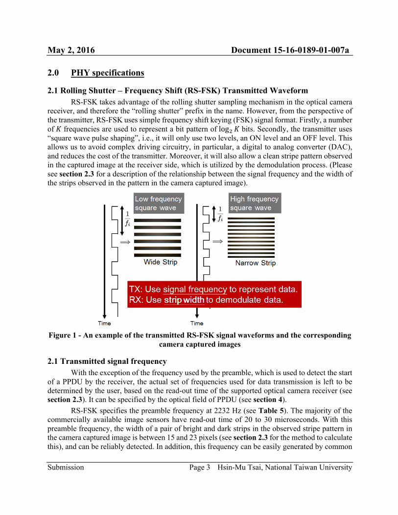
2.1 Rolling Shutter – Frequency Shift (RS-FSK) Transmitted Waveform RS-FSK takes advantage of the rolling shutter sampling mechanism in the optical camera
receiver, and therefore the “rolling shutter” prefix in the name. However, from the perspective of the transmitter, RS-FSK uses simple frequency shift keying (FSK) signal format. Firstly, a number of 𝐾 frequencies are used to represent a bit pattern of logL 𝐾 bits. Secondly, the transmitter uses “square wave pulse shaping”, i.e., it will only use two levels, an ON level and an OFF level. This allows us to avoid complex driving circuitry, in particular, a digital to analog converter (DAC), and reduces the cost of the transmitter. Moreover, it will also allow a clean stripe pattern observed in the captured image at the receiver side, which is utilized by the demodulation process. (Please see section 2.3 for a description of the relationship between the signal frequency and the width of the strips observed in the pattern in the camera captured image).
Figure 1 - An example of the transmitted RS-FSK signal waveforms and the corresponding
camera captured images
2.1 Transmitted signal frequency With the exception of the frequency used by the preamble, which is used to detect the start of a PPDU by the receiver, the actual set of frequencies used for data transmission is left to be determined by the user, based on the read-out time of the supported optical camera receiver (see section 2.3). It can be specified by the optical field of PPDU (see section 4). RS-FSK specifies the preamble frequency at 2232 Hz (see Table 5). The majority of the commercially available image sensors have read-out time of 20 to 30 microseconds. With this preamble frequency, the width of a pair of bright and dark strips in the observed stripe pattern in the camera captured image is between 15 and 23 pixels (see section 2.3 for the method to calculate this), and can be reliably detected. In addition, this frequency can be easily generated by common
May 2, 2016 Document 15-16-0189-01-007a
Submission Page 4 Hsin-Mu Tsai, National Taiwan University
microcontroller unit (MCU) running at 8 MHz or 16 MHz with proper clock divider (see section 5.1). Moreover, at the receiving end, the reception of the preamble frequency can be used to calibrate the value of the read-out duration and reduce the error rate. For the set of frequencies used by data packets, it is recommended to use frequencies between 500 Hz and 1.4 KHz. The former corresponds to a strip width of 66 to 100 pixels while the latter corresponds to a stripe width of 23 to 36 pixels.
2.2 Symbol duration RS-FSK uses a symbol duration that equals to the receiving camera’s frame duration. Since most of the cameras use a frame rate of 30 frame per second when capturing video, the default symbol duration is set to be 1/30 second. Note that the symbol can be configured by the use of optional field and PIB attributes in PPDU (see section 5.2).
2.3 Relationship between signal frequency and observed strip width in captured images
In this section we describe the relationship between the transmitted frequency 𝑓 and the strip width 𝑊. Although the standard usually does not specify how the receiver demodulate the transmitted frequency, this background knowledge is required to determine the set of frequencies that is used by the transmitters based on the specification of the receiving optical camera. Therefore, we choose to disclose the information here.
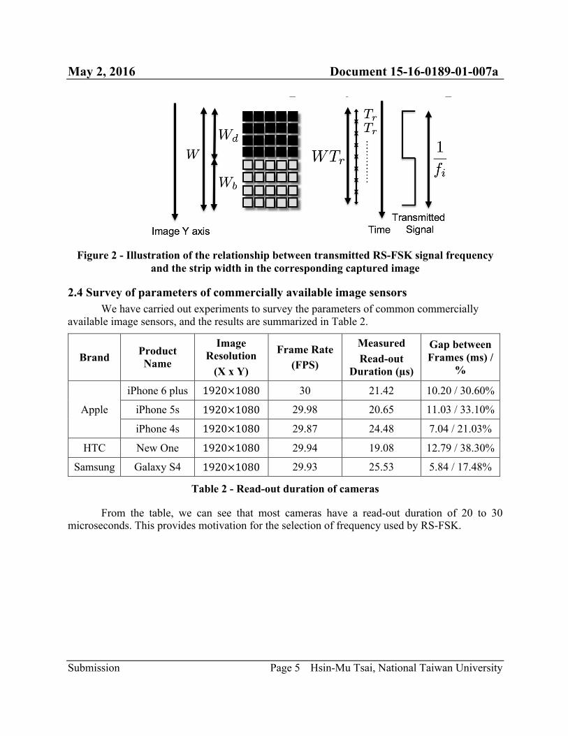
The strip width is defined as the number of pixels occupied by a set of bright strip (exposure during the transmitter is in the ON state) and dark strip (exposure during the transmitter is in the OFF state) in a received image. Note that, for a square wave of frequency 𝑓 Hz, the duration of a complete cycle is O
P seconds. Therefore, for every O
P seconds a camera exposes, it should be able to
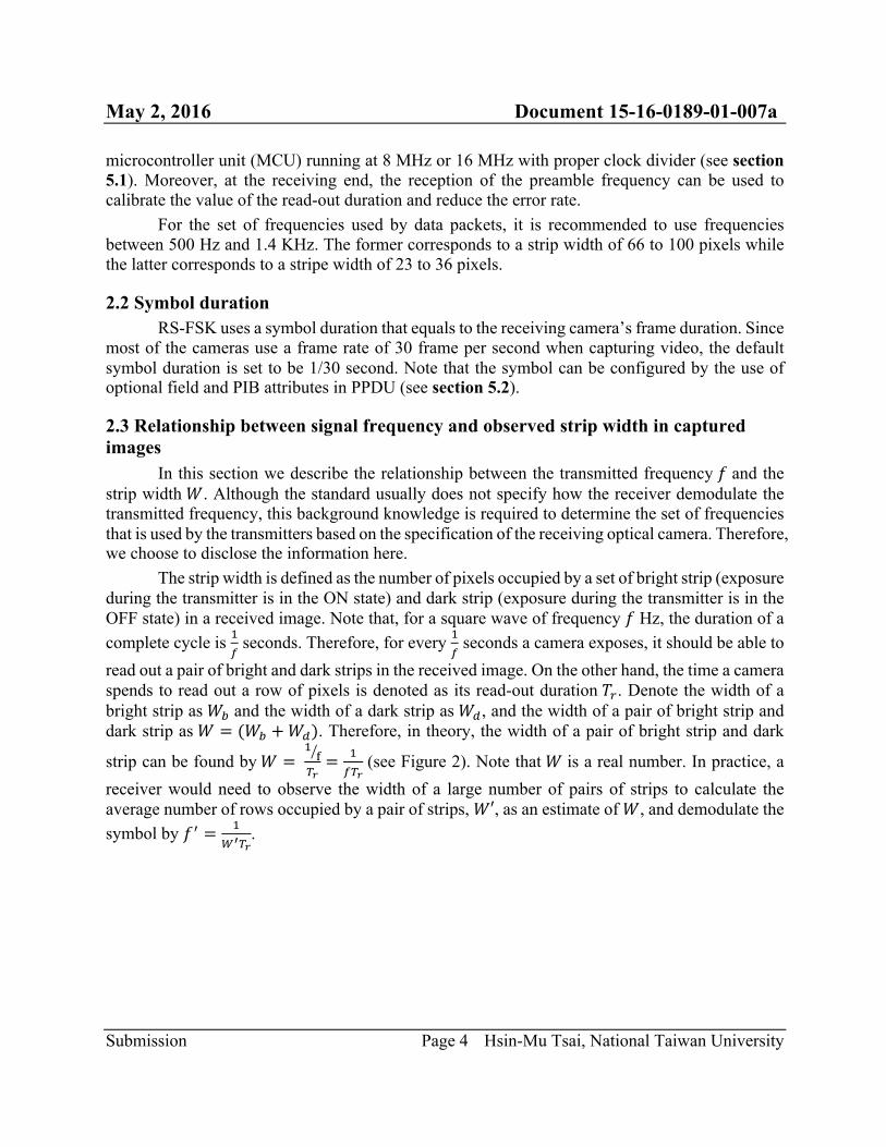
read out a pair of bright and dark strips in the received image. On the other hand, the time a camera spends to read out a row of pixels is denoted as its read-out duration 𝑇R. Denote the width of a bright strip as 𝑊S and the width of a dark strip as 𝑊T, and the width of a pair of bright strip and dark strip as 𝑊 = (𝑊S +𝑊T). Therefore, in theory, the width of a pair of bright strip and dark
strip can be found by𝑊 = OW
XY= O
PXY (see Figure 2). Note that 𝑊 is a real number. In practice, a
receiver would need to observe the width of a large number of pairs of strips to calculate the average number of rows occupied by a pair of strips, 𝑊′, as an estimate of 𝑊, and demodulate the symbol by 𝑓[ = O
\]XY.
May 2, 2016 Document 15-16-0189-01-007a
Submission Page 5 Hsin-Mu Tsai, National Taiwan University
Figure 2 - Illustration of the relationship between transmitted RS-FSK signal frequency
and the strip width in the corresponding captured image
2.4 Survey of parameters of commercially available image sensors We have carried out experiments to survey the parameters of common commercially
available image sensors, and the results are summarized in Table 2.
Brand Product Name
Image Resolution
(X x Y)
Frame Rate (FPS)
Measured Read-out
Duration (µs)
Gap between Frames (ms) /
%
Apple
iPhone 6 plus 1920×1080 30 21.42 10.20 / 30.60%
iPhone 5s 1920×1080 29.98 20.65 11.03 / 33.10%
iPhone 4s 1920×1080 29.87 24.48 7.04 / 21.03%
HTC New One 1920×1080 29.94 19.08 12.79 / 38.30%
Samsung Galaxy S4 1920×1080 29.93 25.53 5.84 / 17.48%
Table 2 - Read-out duration of cameras
From the table, we can see that most cameras have a read-out duration of 20 to 30 microseconds. This provides motivation for the selection of frequency used by RS-FSK.
May 2, 2016 Document 15-16-0189-01-007a
Submission Page 6 Hsin-Mu Tsai, National Taiwan University
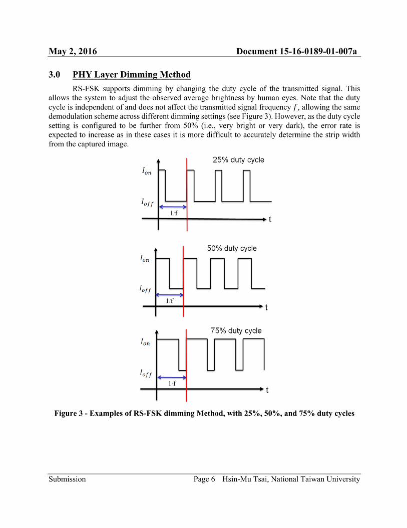
3.0 PHY Layer Dimming Method RS-FSK supports dimming by changing the duty cycle of the transmitted signal. This
allows the system to adjust the observed average brightness by human eyes. Note that the duty cycle is independent of and does not affect the transmitted signal frequency 𝑓, allowing the same demodulation scheme across different dimming settings (see Figure 3). However, as the duty cycle setting is configured to be further from 50% (i.e., very bright or very dark), the error rate is expected to increase as in these cases it is more difficult to accurately determine the strip width from the captured image.
Figure 3 - Examples of RS-FSK dimming Method, with 25%, 50%, and 75% duty cycles
May 2, 2016 Document 15-16-0189-01-007a
Submission Page 7 Hsin-Mu Tsai, National Taiwan University
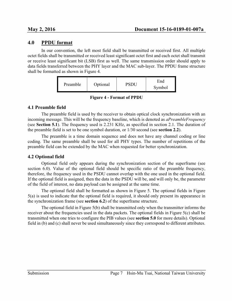
4.0 PPDU format In our convention, the left most field shall be transmitted or received first. All multiple
octet fields shall be transmitted or received least significant octet first and each octet shall transmit or receive least significant bit (LSB) first as well. The same transmission order should apply to data fields transferred between the PHY layer and the MAC sub-layer. The PPDU frame structure shall be formatted as shown in Figure 4.
Preamble Optional PSDU End
Symbol
Figure 4 - Format of PPDU
4.1 Preamble field The preamble field is used by the receiver to obtain optical clock synchronization with an
incoming message. This will be the frequency baseline, which is denoted as aPreambleFrequency (see Section 5.1). The frequency used is 2.231 KHz, as specified in section 2.1. The duration of the preamble field is set to be one symbol duration, or 1/30 second (see section 2.2).
The preamble is a time domain sequence and does not have any channel coding or line coding. The same preamble shall be used for all PHY types. The number of repetitions of the preamble field can be extended by the MAC when requested for better synchronization.
4.2 Optional field Optional field only appears during the synchronization section of the superframe (see
section 6.0). Value of the optional field should be specific ratio of the preamble frequency, therefore, the frequency used in the PSDU cannot overlap with the one used in the optional field. If the optional field is assigned, then the data in the PSDU will be, and will only be, the parameter of the field of interest, no data payload can be assigned at the same time.
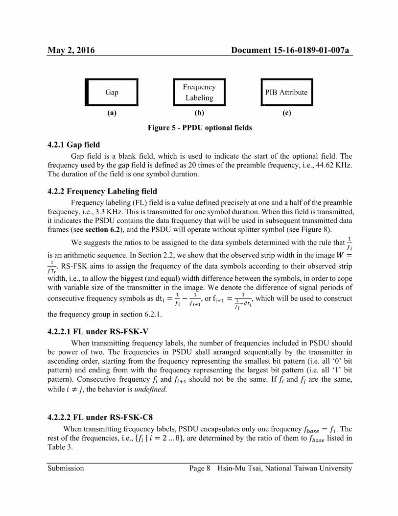
The optional field shall be formatted as shown in Figure 5. The optional fields in Figure 5(a) is used to indicate that the optional field is required, it should only present its appearance in the synchronization frame (see section 6.2) of the superframe structure.
The optional field in Figure 5(b) shall be transmitted only when the transmitter informs the receiver about the frequencies used in the data packets. The optional fields in Figure 5(c) shall be transmitted when one tries to configure the PIB values (see section 5.0 for more details). Optional field in (b) and (c) shall never be used simultaneously since they correspond to different attributes.
May 2, 2016 Document 15-16-0189-01-007a
Submission Page 8 Hsin-Mu Tsai, National Taiwan University
Gap Frequency
Labeling
PIB Attribute
(a) (b) (c)
Figure 5 - PPDU optional fields
4.2.1 Gap field Gap field is a blank field, which is used to indicate the start of the optional field. The
frequency used by the gap field is defined as 20 times of the preamble frequency, i.e., 44.62 KHz. The duration of the field is one symbol duration.
4.2.2 Frequency Labeling field Frequency labeling (FL) field is a value defined precisely at one and a half of the preamble
frequency, i.e., 3.3 KHz. This is transmitted for one symbol duration. When this field is transmitted, it indicates the PSDU contains the data frequency that will be used in subsequent transmitted data frames (see section 6.2), and the PSDU will operate without splitter symbol (see Figure 8).
We suggests the ratios to be assigned to the data symbols determined with the rule that OP^
is an arithmetic sequence. In Section 2.2, we show that the observed strip width in the image𝑊 =OPXY
. RS-FSK aims to assign the frequency of the data symbols according to their observed strip width, i.e., to allow the biggest (and equal) width difference between the symbols, in order to cope with variable size of the transmitter in the image. We denote the difference of signal periods of consecutive frequency symbols asdtD =
OP^− O
P^`a, orfDcO =
Oad^6Te^
, which will be used to construct
the frequency group in section 6.2.1.
4.2.2.1 FL under RS-FSK-V When transmitting frequency labels, the number of frequencies included in PSDU should
be power of two. The frequencies in PSDU shall arranged sequentially by the transmitter in ascending order, starting from the frequency representing the smallest bit pattern (i.e. all ‘0’ bit pattern) and ending from with the frequency representing the largest bit pattern (i.e. all ‘1’ bit pattern). Consecutive frequency 𝑓f and 𝑓fcO should not be the same. If 𝑓f and 𝑓g are the same, while𝑖 ≠ 𝑗, the behavior is undefined.
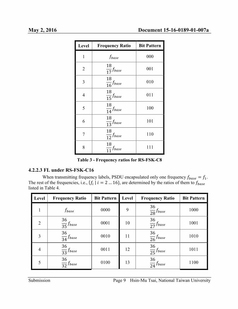
4.2.2.2 FL under RS-FSK-C8 When transmitting frequency labels, PSDU encapsulates only one frequency𝑓Sklm = 𝑓O. The
rest of the frequencies, i.e., 𝑓f 𝑖 = 2…8}, are determined by the ratio of them to 𝑓Sklm listed in Table 3.
May 2, 2016 Document 15-16-0189-01-007a
Submission Page 9 Hsin-Mu Tsai, National Taiwan University
Level Frequency Ratio Bit Pattern
1 𝑓Sklm 000
2 1817 𝑓Sklm 001
3 1816 𝑓Sklm 010
4 1815 𝑓Sklm 011
5 1814 𝑓Sklm 100
6 1813 𝑓Sklm 101
7 1812 𝑓Sklm 110
8 1811 𝑓Sklm 111
Table 3 - Frequency ratios for RS-FSK-C8
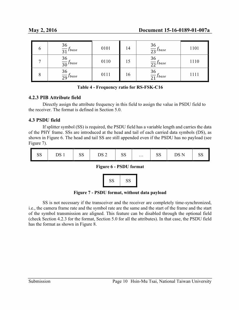
4.2.2.3 FL under RS-FSK-C16 When transmitting frequency labels, PSDU encapsulated only one frequency𝑓Sklm = 𝑓O.
The rest of the frequencies, i.e., 𝑓f 𝑖 = 2…16}, are determined by the ratios of them to 𝑓Sklm listed in Table 4.
Level Frequency Ratio Bit Pattern Level Frequency Ratio Bit Pattern
1 𝑓Sklm 0000 9 3628 𝑓Sklm 1000
2 3635 𝑓Sklm 0001 10
3627 𝑓Sklm 1001
3 3634 𝑓Sklm 0010 11
3626 𝑓Sklm 1010
4 3633 𝑓Sklm 0011 12
3625 𝑓Sklm 1011
5 3632 𝑓Sklm 0100 13 36
24 𝑓Sklm 1100
May 2, 2016 Document 15-16-0189-01-007a
Submission Page 10 Hsin-Mu Tsai, National Taiwan University
6 3631 𝑓Sklm 0101 14
3623 𝑓Sklm 1101
7 3630 𝑓Sklm 0110 15
3622 𝑓Sklm 1110
8 3629 𝑓Sklm 0111 16 36
21 𝑓Sklm 1111
Table 4 - Frequency ratio for RS-FSK-C16
4.2.3 PIB Attribute field Directly assign the attribute frequency in this field to assign the value in PSDU field to
the receiver. The format is defined in Section 5.0.
4.3 PSDU field If splitter symbol (SS) is required, the PSDU field has a variable length and carries the data
of the PHY frame. SSs are introduced at the head and tail of each carried data symbols (DS), as shown in Figure 6. The head and tail SS are still appended even if the PSDU has no payload (see Figure 7).
SS DS 1 SS DS 2 SS … SS DS N SS
Figure 6 - PSDU format
SS SS
Figure 7 - PSDU format, without data payload
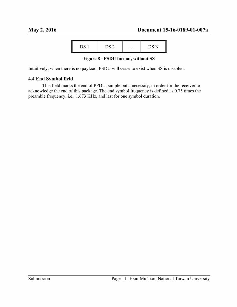
SS is not necessary if the transceiver and the receiver are completely time-synchronized, i.e., the camera frame rate and the symbol rate are the same and the start of the frame and the start of the symbol transmission are aligned. This feature can be disabled through the optional field (check Section 4.2.3 for the format, Section 5.0 for all the attributes). In that case, the PSDU field has the format as shown in Figure 8.
May 2, 2016 Document 15-16-0189-01-007a
Submission Page 11 Hsin-Mu Tsai, National Taiwan University
DS 1 DS 2 … DS N
Figure 8 - PSDU format, without SS
Intuitively, when there is no payload, PSDU will cease to exist when SS is disabled.
4.4 End Symbol field This field marks the end of PPDU, simple but a necessity, in order for the receiver to
acknowledge the end of this package. The end symbol frequency is defined as 0.75 times the preamble frequency, i.e., 1.673 KHz, and last for one symbol duration.
May 2, 2016 Document 15-16-0189-01-007a
Submission Page 12 Hsin-Mu Tsai, National Taiwan University
5.0 PHY constants and PIB attributes This sub-clause specifies the constants and attributes required by the PHY.
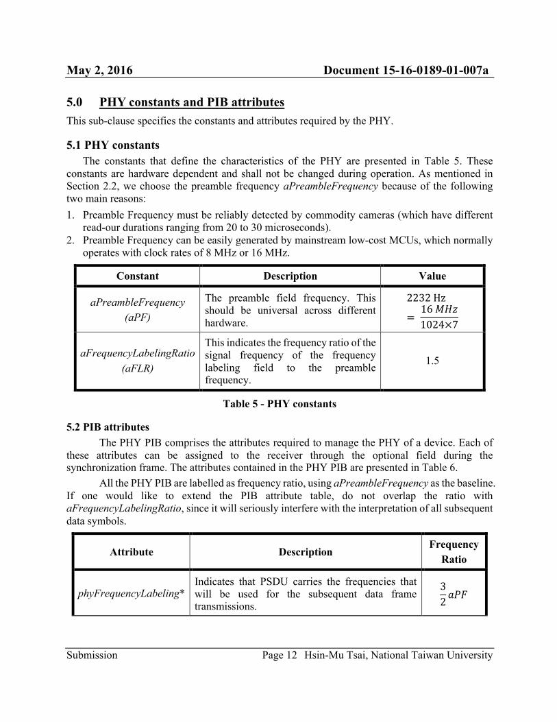
5.1 PHY constants The constants that define the characteristics of the PHY are presented in Table 5. These
constants are hardware dependent and shall not be changed during operation. As mentioned in Section 2.2, we choose the preamble frequency aPreambleFrequency because of the following two main reasons: 1. Preamble Frequency must be reliably detected by commodity cameras (which have different
read-our durations ranging from 20 to 30 microseconds). 2. Preamble Frequency can be easily generated by mainstream low-cost MCUs, which normally
operates with clock rates of 8 MHz or 16 MHz.
Constant Description Value
aPreambleFrequency (aPF)
The preamble field frequency. This should be universal across different hardware.
2232Hz
= 16𝑀𝐻𝑧1024×7
aFrequencyLabelingRatio (aFLR)
This indicates the frequency ratio of the signal frequency of the frequency labeling field to the preamble frequency.
1.5
Table 5 - PHY constants
5.2 PIB attributes The PHY PIB comprises the attributes required to manage the PHY of a device. Each of
these attributes can be assigned to the receiver through the optional field during the synchronization frame. The attributes contained in the PHY PIB are presented in Table 6.
All the PHY PIB are labelled as frequency ratio, using aPreambleFrequency as the baseline. If one would like to extend the PIB attribute table, do not overlap the ratio with aFrequencyLabelingRatio, since it will seriously interfere with the interpretation of all subsequent data symbols.
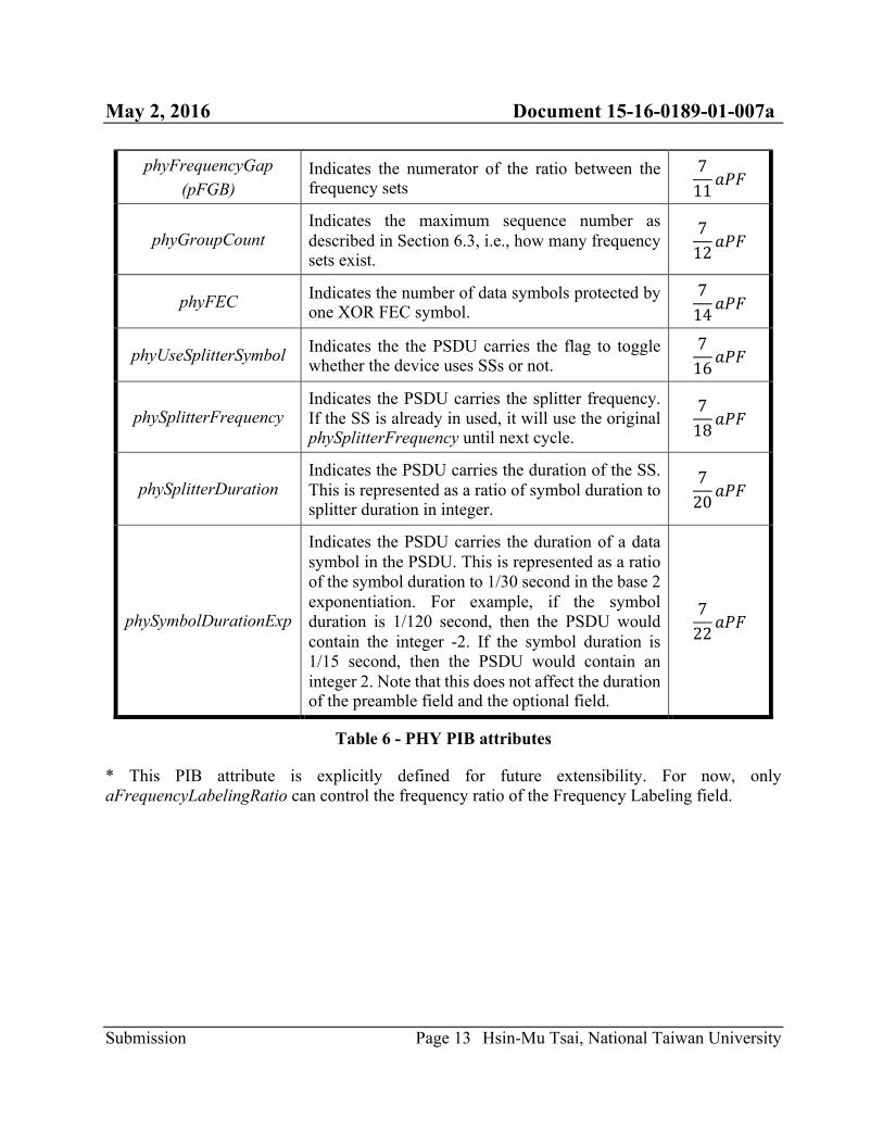
Attribute Description Frequency
Ratio
phyFrequencyLabeling* Indicates that PSDU carries the frequencies that will be used for the subsequent data frame transmissions.
32𝑎𝑃𝐹
May 2, 2016 Document 15-16-0189-01-007a
Submission Page 13 Hsin-Mu Tsai, National Taiwan University
phyFrequencyGap (pFGB)
Indicates the numerator of the ratio between the frequency sets
711𝑎𝑃𝐹
phyGroupCount Indicates the maximum sequence number as described in Section 6.3, i.e., how many frequency sets exist.
712𝑎𝑃𝐹
phyFEC Indicates the number of data symbols protected by one XOR FEC symbol.
714𝑎𝑃𝐹
phyUseSplitterSymbol Indicates the the PSDU carries the flag to toggle whether the device uses SSs or not.
716𝑎𝑃𝐹
phySplitterFrequency Indicates the PSDU carries the splitter frequency. If the SS is already in used, it will use the original phySplitterFrequency until next cycle.
718𝑎𝑃𝐹
phySplitterDuration Indicates the PSDU carries the duration of the SS. This is represented as a ratio of symbol duration to splitter duration in integer.
720𝑎𝑃𝐹
phySymbolDurationExp
Indicates the PSDU carries the duration of a data symbol in the PSDU. This is represented as a ratio of the symbol duration to 1/30 second in the base 2 exponentiation. For example, if the symbol duration is 1/120 second, then the PSDU would contain the integer -2. If the symbol duration is 1/15 second, then the PSDU would contain an integer 2. Note that this does not affect the duration of the preamble field and the optional field.
722𝑎𝑃𝐹
Table 6 - PHY PIB attributes
* This PIB attribute is explicitly defined for future extensibility. For now, only aFrequencyLabelingRatio can control the frequency ratio of the Frequency Labeling field.
May 2, 2016 Document 15-16-0189-01-007a
Submission Page 14 Hsin-Mu Tsai, National Taiwan University
6.0 Superframe Structure The transmitter needs to use a superframe structure to control the asynchronous operation
between the transmitter and the receiver. A superframe is bounded by the transmission of a synchronization frame and a series of data frame. The receiver may enter a low-power mode if the synchronization frame indicates the appropriate time (the inactive frame) to do so.
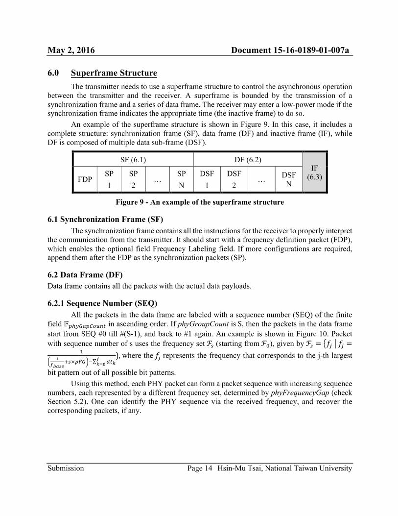
An example of the superframe structure is shown in Figure 9. In this case, it includes a complete structure: synchronization frame (SF), data frame (DF) and inactive frame (IF), while DF is composed of multiple data sub-frame (DSF).
SF (6.1) DF (6.2) IF
(6.3) FDP SP 1
SP 2
… SP N
DSF 1
DSF 2
… DSF N
Figure 9 - An example of the superframe structure
6.1 Synchronization Frame (SF) The synchronization frame contains all the instructions for the receiver to properly interpret
the communication from the transmitter. It should start with a frequency definition packet (FDP), which enables the optional field Frequency Labeling field. If more configurations are required, append them after the FDP as the synchronization packets (SP).
6.2 Data Frame (DF) Data frame contains all the packets with the actual data payloads.
6.2.1 Sequence Number (SEQ) All the packets in the data frame are labeled with a sequence number (SEQ) of the finite
field 𝔽~���k~����e in ascending order. If phyGroupCount isS, then the packets in the data frame start from SEQ #0 till #(S-1), and back to #1 again. An example is shown in Figure 10. Packet with sequence number of s uses the frequency set ℱl (starting fromℱ�), given by ℱl = 𝑓g 𝑓g =
Oa
d����cl×~�� 6 Te�
����
},where the 𝑓g represents the frequency that corresponds to the j-th largest
bit pattern out of all possible bit patterns. Using this method, each PHY packet can form a packet sequence with increasing sequence
numbers, each represented by a different frequency set, determined by phyFrequencyGap (check Section 5.2). One can identify the PHY sequence via the received frequency, and recover the corresponding packets, if any.
May 2, 2016 Document 15-16-0189-01-007a
Submission Page 15 Hsin-Mu Tsai, National Taiwan University
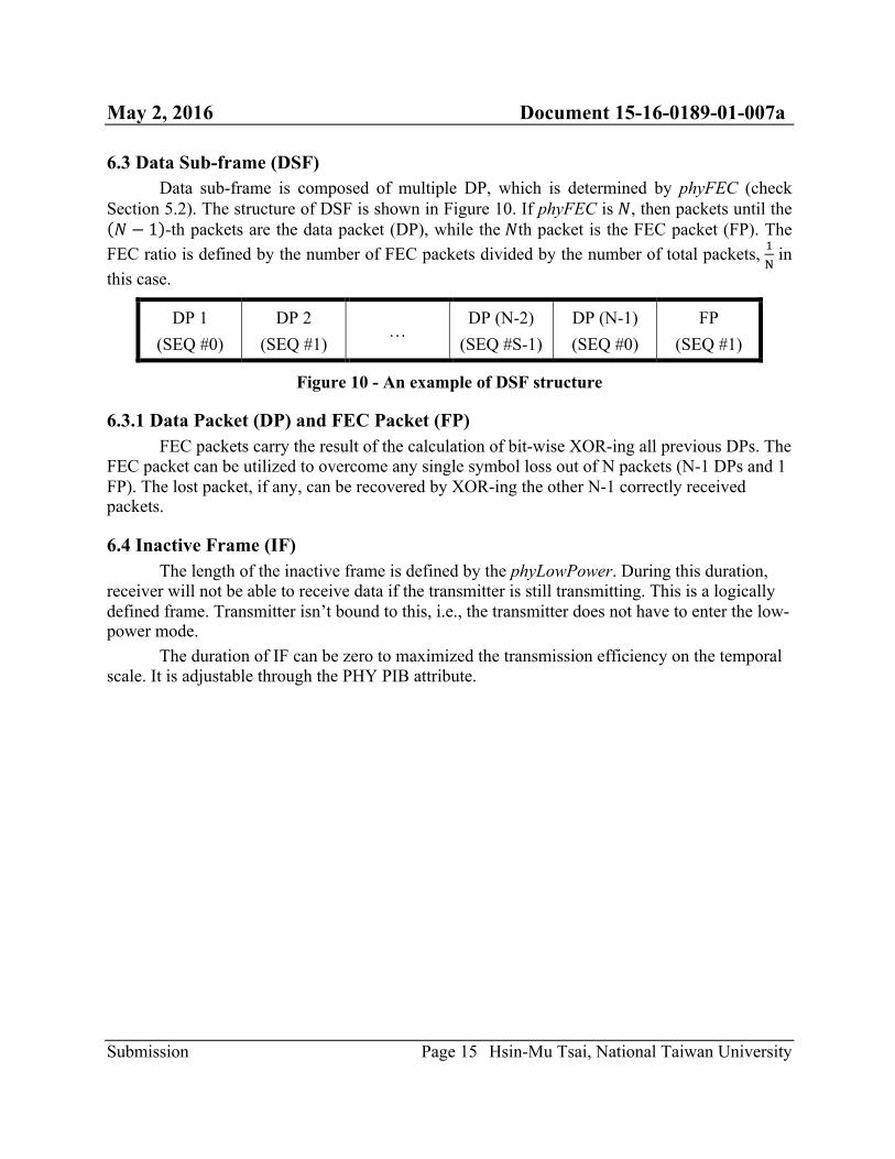
6.3 Data Sub-frame (DSF) Data sub-frame is composed of multiple DP, which is determined by phyFEC (check
Section 5.2). The structure of DSF is shown in Figure 10. If phyFEC is 𝑁, then packets until the 𝑁 − 1 -th packets are the data packet (DP), while the 𝑁th packet is the FEC packet (FP). The
FEC ratio is defined by the number of FEC packets divided by the number of total packets, O�
in this case.
DP 1 (SEQ #0)
DP 2 (SEQ #1)
… DP (N-2)
(SEQ #S-1) DP (N-1) (SEQ #0)
FP (SEQ #1)
Figure 10 - An example of DSF structure
6.3.1 Data Packet (DP) and FEC Packet (FP) FEC packets carry the result of the calculation of bit-wise XOR-ing all previous DPs. The
FEC packet can be utilized to overcome any single symbol loss out of N packets (N-1 DPs and 1 FP). The lost packet, if any, can be recovered by XOR-ing the other N-1 correctly received packets.
6.4 Inactive Frame (IF) The length of the inactive frame is defined by the phyLowPower. During this duration,
receiver will not be able to receive data if the transmitter is still transmitting. This is a logically defined frame. Transmitter isn’t bound to this, i.e., the transmitter does not have to enter the low-power mode.
The duration of IF can be zero to maximized the transmission efficiency on the temporal scale. It is adjustable through the PHY PIB attribute.
May 2, 2016 Document 15-16-0189-01-007a
Submission Page 16 Hsin-Mu Tsai, National Taiwan University
7.0 MAC frame formats This sub-clause specifies the format of the MAC frame (MPDU). Each MAC frame consists
of the following basic components: a) A MFH, which comprises frame control, sequence number and address information. b) A MFDU, of variable length, which contains information specific to the frame type.
Acknowledgement frames do not contain a payload. c) A MFT, which contains a FCS.
The frames in the MAC sub-layer are described as a sequence of fields in a specific order. All frame formats in this sub-clause are depicted in the order in which they are transmitted by the PHY, from left to right, where the left most bit is transmitted first in time. Bits within each field are numbered from 0 (left most and least significant) to 𝑘 − 1 (right most and most significant), where the length of the field is 𝑘 bits. Fields that are longer than a single octet are sent to the PHY in the order form the octet containing the lowest numbered bits to the octet containing the highest numbered bits.
For every MAC frame, all reserved bits shall be ignored upon receipt.
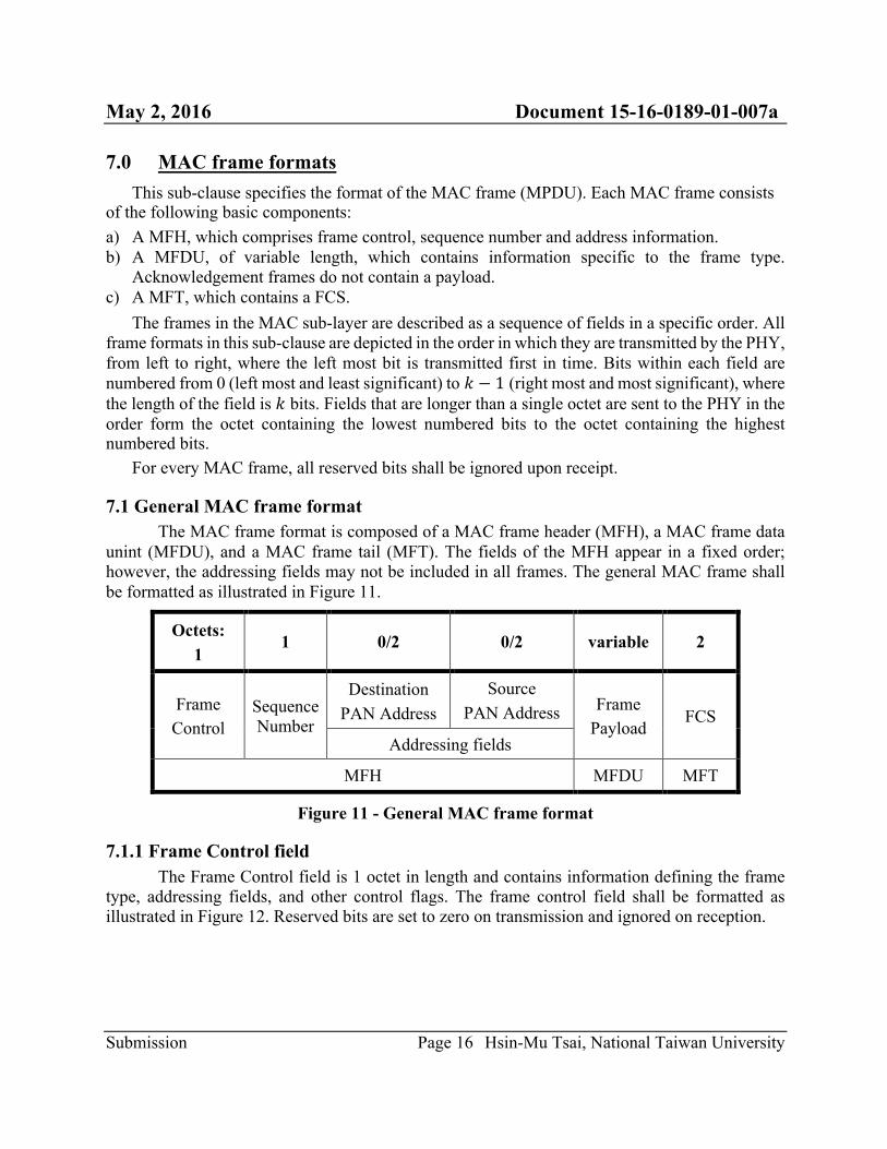
7.1 General MAC frame format The MAC frame format is composed of a MAC frame header (MFH), a MAC frame data
unint (MFDU), and a MAC frame tail (MFT). The fields of the MFH appear in a fixed order; however, the addressing fields may not be included in all frames. The general MAC frame shall be formatted as illustrated in Figure 11.
Octets: 1
1 0/2 0/2 variable 2
Frame Control
Sequence Number
Destination PAN Address
Source PAN Address Frame
Payload FCS
Addressing fields
MFH MFDU MFT
Figure 11 - General MAC frame format
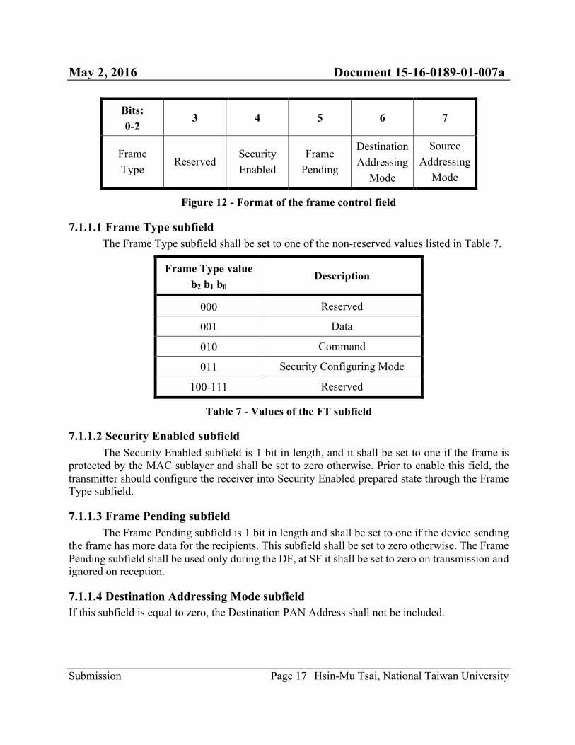
7.1.1 Frame Control field The Frame Control field is 1 octet in length and contains information defining the frame
type, addressing fields, and other control flags. The frame control field shall be formatted as illustrated in Figure 12. Reserved bits are set to zero on transmission and ignored on reception.
May 2, 2016 Document 15-16-0189-01-007a
Submission Page 17 Hsin-Mu Tsai, National Taiwan University
Bits: 0-2
3 4 5 6 7
Frame Type
Reserved Security Enabled
Frame Pending
Destination Addressing
Mode
Source Addressing
Mode
Figure 12 - Format of the frame control field
7.1.1.1 Frame Type subfield The Frame Type subfield shall be set to one of the non-reserved values listed in Table 7.
Frame Type value b2 b1 b0
Description
000 Reserved
001 Data
010 Command
011 Security Configuring Mode
100-111 Reserved
Table 7 - Values of the FT subfield
7.1.1.2 Security Enabled subfield The Security Enabled subfield is 1 bit in length, and it shall be set to one if the frame is
protected by the MAC sublayer and shall be set to zero otherwise. Prior to enable this field, the transmitter should configure the receiver into Security Enabled prepared state through the Frame Type subfield.
7.1.1.3 Frame Pending subfield The Frame Pending subfield is 1 bit in length and shall be set to one if the device sending
the frame has more data for the recipients. This subfield shall be set to zero otherwise. The Frame Pending subfield shall be used only during the DF, at SF it shall be set to zero on transmission and ignored on reception.
7.1.1.4 Destination Addressing Mode subfield If this subfield is equal to zero, the Destination PAN Address shall not be included.
May 2, 2016 Document 15-16-0189-01-007a
Submission Page 18 Hsin-Mu Tsai, National Taiwan University
7.1.1.5 Source Addressing Mode subfield If this subfield is equal to zero, the Source PAN Address shall not be included.
7.1.2 Sequence Number field The Sequence Number field is 1 octet in length and specifies the sequence identifier for the frame.
7.1.3.1 Destination PAN Address field The Destination PAN Address, when present, is 2 octets in length, and specifies the address
of the intended recipient of the frame. A 16-bit value of 0xFFFF in this field shall represent the broadcast address, which shall be accepted as a valid 16-bit address by all devices currently listening to the channel.
This field shall be included in the MAC frame only if the Destination Addressing Mode subfield of the frame control field is nonzero.
7.1.3.2 Source PAN Address field The Source PAN Address, when present, is 2 octets in length, and specifies the address of
the originator of the frame. This field shall be included in the MAC frame only if the Source Addressing Mode subfield of the frame control field is nonzero.
7.2 MFDU The MFDU contains the frame payload, which has a variable length and contains
information specific to individual frame types. If the frame control is configured to Security Enabled previously, then the frame payload is protected as defined by the security suite selected at that time.
7.3 MFT MFT contains only the frame checksum (FCS). The FCS field is 2 octets in length and is
explained in somewhere else in the document. The FCS is calculated over the MFH and MSDU part of the frame. The FCS shall be only generated for payloads greater than zero bytes.

May 2, 2016 Document 15-16-0189-01-007a
Submission Page 19 Hsin-Mu Tsai, National Taiwan University
8.0 MAC constants and PIB attributes This sub-clause specifies the constants and attributes required by the MAC sublayer.
8.1 MAC constants Currently nothing is required.
8.2 MAC PIB attributes Currently nothing is required.