Embed Size (px)
Citation preview
March 2016 IEEE 802.15 Doc Number 14/0309r20
IEEE P802.15Wireless Personal Area Networks
Project IEEE P802.15 Working Group for Wireless Personal Area Networks (WPANs)
Title TG3d Technical Requirements Document
Date Submitted
15 March 2016
Source Thomas Kürner (editor),Technische Universität Branschweig,Schleinitzstr. 22,38106 Braunschweig, Germany
Voice : +49 531 391 2416Fax: +49 531 391 5192E-mail: [email protected]
Re:
Abstract TG3d Technical Requirements
Purpose Supporting document for the development of the amendment 3d of IEEE 802.15.3
Notice This document has been prepared to assist the IEEE P802.15. It is offered as a basis for discussion and is not binding on the contributing individual(s) or organization(s). The material in this document is subject to change in form and content after further study. The contributor(s) reserve(s) the right to add, amend or withdraw material contained herein.
Release The contributor acknowledges and accepts that this contribution becomes the property of IEEE and may be made publicly available by P802.15.
Submission Page Thomas Kürner (TU Braunschweig)

March 2016 IEEE 802.15 Doc Number 14/0309r20
Submission Page Thomas Kürner (TU Braunschweig)

March 2016 IEEE 802.15 Doc Number 14/0309r20
List of contributorsKiyoshi Toshimitsu Toshiba CorporationIchiro Seto Toshiba CorporationKen Hiraga NTT CorporationKeiji Akiyama Sony CorporationThomas Kürner TU BraunschweigSebastian Rey TU BraunschweigTuncer Baykas Istanbul Medipol UniversityKe Guan Beijing Jiaotong UniversityIwao Hosako NICTAkifumi Ksasmatsu NICTHiroyo Ogawa NICT
Submission Page Thomas Kürner (TU Braunschweig)

March 2016 IEEE 802.15 Doc Number 14/0309r20
Table of Contents
1 DEFINITIONS AND ABBREVATIONS:............................................................................................................ 5
2 GENERAL GUIDELINES [1]........................................................................................................................... 7
3 INTRODUCTION.......................................................................................................................................... 9
4 PROTOCOL REFERENCE MODEL.................................................................................................................. 9
5 USE CASE SUMMARY.................................................................................................................................. 9
6 TRD SUMMARY........................................................................................................................................ 10
7 TOPOLOGY AND LINK SWITCHING............................................................................................................ 10
8 DATA RATES............................................................................................................................................. 11
9 TRANSMISSION RANGE............................................................................................................................ 11
10 OPERATIONAL FREQUENCY BANDS........................................................................................................... 12
11 REGULATORY REQUIREMENTS AND COEXISTENCE....................................................................................13
11.1 REQUIREMENTS FROM THE RADIO REGULATIONS...............................................................................................1311.1.1 Potentially Critical Interference Scenarios in the THz frequency band...........................................1311.1.2 Spectral Masks between Active Services and Earth Exploration Services (EESS)............................15
11.2 COEXISTENCE AMONG DIFFERENT USE CASES.....................................................................................................17
12 CHANNEL MODELS................................................................................................................................... 17
13 LINK BUDGET AND SNR ANALYSIS............................................................................................................. 17
14 MEDIA ACCESS MECHANISM.................................................................................................................... 18
14.1 BEAM STEERED OR CONTROL CHANNEL ASSISTED DEVICE DISCOVERY......................................................................1814.2 COORDINATION...........................................................................................................................................1814.3 BEACONING................................................................................................................................................1814.4 FAST CONNECTION SETUP SCHEME..................................................................................................................19
15 I/O INTERFACES AND MEMORY BUFFER CONSIDERATIONS.......................................................................19
16 SECURITY MECHANISMS........................................................................................................................... 19
17 SIZE AND POWER..................................................................................................................................... 19
REFERENCES...................................................................................................................................................... 20
Submission Page Thomas Kürner (TU Braunschweig)
March 2016 IEEE 802.15 Doc Number 14/0309r20
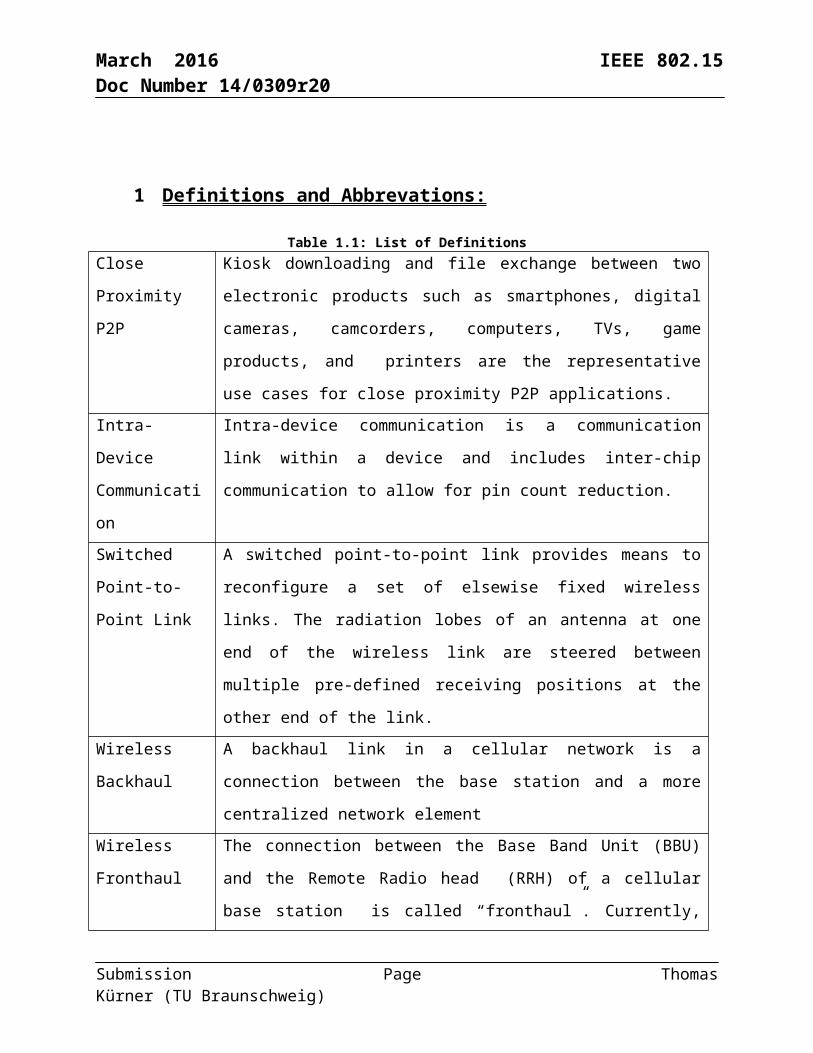
1 Definitions and Abbrevations:
Table 1.1: List of DefinitionsClose Proximity
P2P
Kiosk downloading and file exchange between two electronic products
such as smartphones, digital cameras, camcorders, computers, TVs, game
products, and printers are the representative use cases for close proximity
P2P applications.
Intra-Device
Communication
Intra-device communication is a communication link within a device and
includes inter-chip communication to allow for pin count reduction.
Switched Point-
to-Point Link
A switched point-to-point link provides means to reconfigure a set of
elsewise fixed wireless links. The radiation lobes of an antenna at one end
of the wireless link are steered between multiple pre-defined receiving
positions at the other end of the link.
Wireless
Backhaul
A backhaul link in a cellular network is a connection between the base
station and a more centralized network element
Wireless
Fronthaul
The connection between the Base Band Unit (BBU) and the Remote Radio
head (RRH) of a cellular base station is called “fronthaul”. Currently,
ITU-T SG15 defines mobile fronthaul including Radio over Fiber (RoF)
Submission Page Thomas Kürner (TU Braunschweig)

March 2016 IEEE 802.15 Doc Number 14/0309r20
Table 1.2: List of AbbrevationsARD Application Requirements Document
EESS Earth Exploration Services
EIRP Equivalent Isotropically Radiated Power
MAC Medium Access Control
P2P Peer to Peer
QoS Quality of Service
RX Receiver
SWaP Size, Weight and Power
THz Terahertz
TRD Technical Requirements Document
TRX Transceiver
TX Transmitter
Submission Page Thomas Kürner (TU Braunschweig)

March 2016 IEEE 802.15 Doc Number 14/0309r20
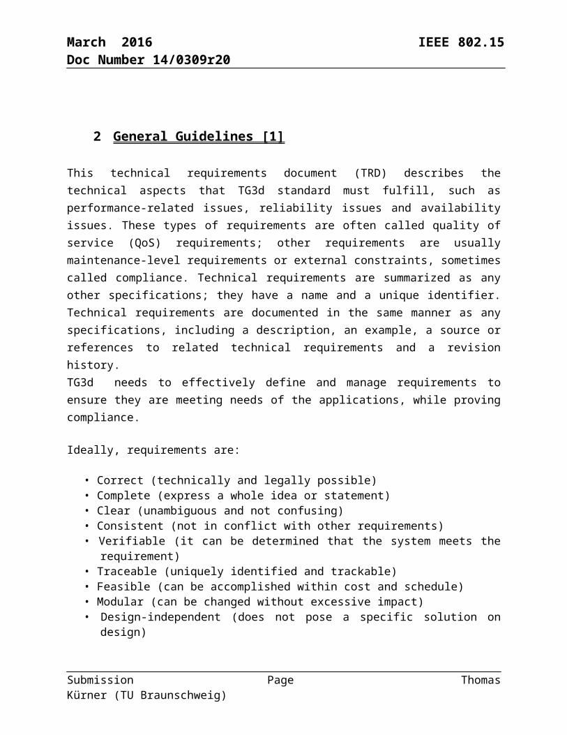
2 General Guidelines [1]
This technical requirements document (TRD) describes the technical aspects that TG3d standard must fulfill, such as performance-related issues, reliability issues and availability issues. These types of requirements are often called quality of service (QoS) requirements; other requirements are usually maintenance-level requirements or external constraints, sometimes called compliance. Technical requirements are summarized as any other specifications; they have a name and a unique identifier. Technical requirements are documented in the same manner as any specifications, including a description, an example, a source or references to related technical requirements and a revision history.TG3d needs to effectively define and manage requirements to ensure they are meeting needs of the applications, while proving compliance.
Ideally, requirements are:
• Correct (technically and legally possible) • Complete (express a whole idea or statement) • Clear (unambiguous and not confusing) • Consistent (not in conflict with other requirements) • Verifiable (it can be determined that the system meets the requirement) • Traceable (uniquely identified and trackable) • Feasible (can be accomplished within cost and schedule) • Modular (can be changed without excessive impact) • Design-independent (does not pose a specific solution on design)
Each requirement must first form a complete sentence, containing a subject and a predicate. These sentences must consistently use the verb “shall”, “will” or “must” to show the requirement's mandatory nature, and “should” or “may” to show that the requirement is optional. The whole requirement specifies a desired end goal or result and contains a success criterion or other measurable indication of the quality.
The TRD needs to capture these levels of user requirements, maintaining intelligent traceability and change impact analysis between them.
Typical constraint requirements can specify:
• Performance • Interfaces • Security • Safety • Reliability
Submission Page Thomas Kürner (TU Braunschweig)
March 2016 IEEE 802.15 Doc Number 14/0309r20
• Availability • Maintainability
An efficient way of writing better requirements is to ensure they are clearly mapped to test cases. Making sure each requirement is clearly verifiable from the start, not only helps prepare later phases of the project, it also puts the developer in the correct state of mind. Requirements and their associated tests must also indicate what the system should not do, and what happens at the limits (degraded mode). This rule also applies for compliance requirements: indicating how they shall be tested is a good way to write better requirements.
Submission Page Thomas Kürner (TU Braunschweig)

PHY_SAP: PHY Service Access PointPLCP: PHY Layer Convergence Protocol
MAC_SAP: MAC Service Access Point
March 2016 IEEE 802.15 Doc Number 14/0309r20
3 Introduction
This document provides the technical requirements of the project to develop the amendment 3d to IEEE 802.15.3 to enable data rates of 100 Gbps for switched point-to-point according to the PAR and CSD of this project [2,3]. This document will provide guidance and requirements on how to respond to a call for proposals.
4 Protocol Reference Model
The communication protocol reference model used for this document is shown in Figure 1.
5 Use case summary The use cases and applications with performance and functional requirements are described in the Applicatons Requirements Document (ARD) [4].
Submission Page Thomas Kürner (TU Braunschweig)
PMD: Physical Medium Dependent (radio)
Figure 4.1: Reference partitioning

March 2016 IEEE 802.15 Doc Number 14/0309r20
6 TRD Summary
This clause contains an overall summary of the rest of the document, mentioning the highlights such as PHY types (assuming multiple options), data rates, topology options (e.g. star, point-to-point, etc.), and MAC frame formats.
This document describes the technical requirements to define a wireless switched point-to-point physical layer to IEEE Std. 802.15.3 operating at a nominal PHY data rate of 100 Gbps with fallbacks to lower data rates as needed. Operation is considered in bands from 252 GHz to 325 GHz. Additionally, the technical requirements for modifications to the Medium Access Control (MAC) layer, needed to support this new physical layer, are defined. The requirements in terms of transmission ranges depends on the specific use cases defined in the applications requirements document [4] and spans a range of 3 cm to 200m. The required Bit error rates at the PHY_SAP depend also on the defined use cases and span a range from 10 -6 to 10-12. The proposals shall also comply with the regulatory requirements taking into account the specific situation for carrier frequencies beyond 275 GHz as defined in the radio regulations [9].
7 Topology and Link Switching
This clause identifies operational topologies
In all use cases the topology will be point-to-point (P2P) and limited to two active devices. Each of the devices will contain both a transmitter and receiver and is thefore denoted as a transceiver (TRX). It may be necessary to switch between several links, see Figure 7.1. The possibility for link switching between two connections is mandatory. Link switching during a running connection is optional. Obviously this is use case dependent since for some use cases link switching may not be appropriate.
Figure 7.1: Switched Point-to-Point Links; Link 1 TRX1 to TRX2 switched to link 2 TRX1 to TRX 3
Submission Page Thomas Kürner (TU Braunschweig)
March 2016 IEEE 802.15 Doc Number 14/0309r20
For close proximity communications, due to unsymmetrical nature of the communication the standard shall allow one device containing only a THz transmitter and the other device containing only a THz receiver. This will enable early implementation of THz devices.
8 Data Rate s
The data rates shall be sufficient to support the proposed use cases in conjunction with the operational frequency plan and channel model. This section discusses the data rates, which usually is the basis for different PHY type classes.
The PHY shall at least support the data rates as defined in Table 8.1. For better compatibility with Ethernet a data rate of 40 Gbps may be considered as well
Table 8.1: Data Rates for different use cases
Use case Minimum Data Rate in Gb/s
Required Data Rate in Gb/s at the higher end
Required BER after error correction at PHY-SAP
Intra-Device Communication 1 100 10-12Close Proximity Communication 1 100 10-6Wireless Fronthauling 101 100 10-12 Wireless Backhauling 10 100 10-12 Data Center 1 100 10-12
9 Transmission range
1 10 Gbit/s is the maximum data rate available today in CPRI. Hence, this shall be the minimum data rate targeted in the amendment.
Submission Page Thomas Kürner (TU Braunschweig)
March 2016 IEEE 802.15 Doc Number 14/0309r20
The transmission range is driven by use cases in conjunction with the operational frequency plan and channel model. This section discusses the transmission range, which often is the justification for different PHY types.
The data rates specified in section 8 shall at least be achieved for transmissions over the distances specified in table 9.2. For the various use cases different antennas may be applied. In the proposal the antenna characteristics (gain, antenna diagrams) to achieve the transmission distance have to be given (see also section 13).
Submission Page Thomas Kürner (TU Braunschweig)

March 2016 IEEE 802.15 Doc Number 14/0309r20
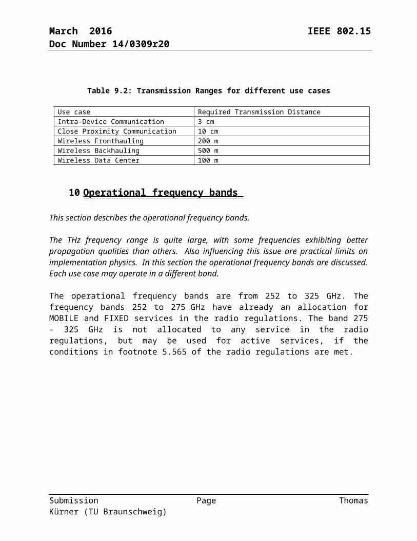
Table 9.2: Transmission Ranges for different use cases
Use case Required Transmission Distance Intra-Device Communication 3 cm Close Proximity Communication 10 cm Wireless Fronthauling 200 mWireless Backhauling 500 m Wireless Data Center 100 m
10 Operational frequency bands
This section describes the operational frequency bands.
The THz frequency range is quite large, with some frequencies exhibiting better propagation qualities than others. Also influencing this issue are practical limits on implementation physics. In this section the operational frequency bands are discussed. Each use case may operate in a different band.
The operational frequency bands are from 252 to 325 GHz. The frequency bands 252 to 275 GHz have already an allocation for MOBILE and FIXED services in the radio regulations. The band 275 – 325 GHz is not allocated to any service in the radio regulations, but may be used for active services, if the conditions in footnote 5.565 of the radio regulations are met.
frequency
Device1
252 GHz 325GHz
frequency
Dev.1
252 GHz 325GHz
frequency252 GHz 325GHz
Dev.1 Dev.1 Dev.1…
Dev.1 Dev.2 Dev.N-1
Dev.N
…
Option 1:
Option 2:
Option 3:
Figure 10.2: Options for utilization of the available spectrum
Submission Page Thomas Kürner (TU Braunschweig)

March 2016 IEEE 802.15 Doc Number 14/0309r20
In Error: Reference source not found three options for the utilization of the available spectrum are introduced. In the first option the whole available bandwidth is dedicated to the communication link of one device. Please note that it’s not required that a proposal utilizes the complete bandwidth of 73 GHz. In option two still the whole bandwidth is dedicated to one communication link but it is split into several subchannels. Again not the whole bandwidth has to be utilized. Such sub-channels can e.g. be realised in an OFDM system or by several RF frontends with smaller bandwidths. This can be beneficial for hardware implementation or for the equalization of the dispersion introduced by the RF frontend in combination with the transmission channel. In the third option sub-channels are dedicated to different links.
In a proposal either option 1 or 2 has to be chosen and the reasons for this decision have to be provided together with the exact parameters for the utilization of the frequency band, e.g. start/stop frequency of all subchannels in case of option 2. Option 3 is out of the scope of this standard, because the standard is for p2p links without multiple devices/services.
11 Regulatory Requirements and Coexistence
The THz bands are currently used for earth science research (mainly passive) and coexistence/protection of these users is necessary to enable the broad acceptance of the technology. This section discusses coexistence and protection issues [6], [7].
The proposals have to include an estimation of the received power level as a function of the distance and direction of interference given the operational characteristics, e. g. transmission power and antenna characteristics, for the interference scenarios described in 11.1 and 11.2.
11.1 Requirements from the Radio Regulations Devices will need to comply with the regulatory requirements specified for THz devices. Unique to THz is that these regulatory requirements will be evolving over the next few years. In this section these issues can be discussed. All regulatory assumptions should be clearly stated.
Active THz systems will have to comply with the ITU Radio Regulations footnote 5.565 [9].
11.1.1 Potentially Critical Interference Scenarios in the THz frequency band
This is an ideal estimation of maximum occurring interference powers using worst case assumptions throughout all scenarios with no additional attenuation due to the impact of weather.
Nomadic devices operated outdoors in rural environment
Submission Page Thomas Kürner (TU Braunschweig)

March 2016 IEEE 802.15 Doc Number 14/0309r20
The assumptions are that the nomadic TX is accidentally pointed in immediate skyward direction as a satellite is passing overhead, directly looking at the ground (0° zenith angle, shortest path), see Fig. 11.1 Also it is assumed that a ground reflection may superimpose constructively with the direct path towards the satellite. This scenario is potentially relevant for the intra-device and kiosk downloading when operated outdoors.
Groundreflection
Figure 11.1: Interference situation for nomadic devices operated outdoors in rural environment
Nomadic devices operated outdoors in urban environment
In this scenario we assume that no objects shadow the direct ray path and that additionally the reflections from buildings around the TX coherently combine at the satellite, see Figure 11.2.
Submission Page Thomas Kürner (TU Braunschweig)
March 2016 IEEE 802.15 Doc Number 14/0309r20
Figure 11.2: Interference situation for nomadic devices operated outdoors in urban environment
Indoor-operated devices are not relevant due to transmission losses; therefore, indoor setups are implicitly covered by the outdoor scenario. This scenario is potentially relevant for the intra-device and kiosk downloading when operated outdoors.
Submission Page Thomas Kürner (TU Braunschweig)

March 2016 IEEE 802.15 Doc Number 14/0309r20
Fixed links with scattering objects close to direct ray path
In this scenario, objects close to the direct ray path may scatter/reflect power in a skyward direction towards the satellite, see Figure 11.3. This scenario is possible despite highly directive antennas. This scenario is relevant for the backhauling/fronthaulimg use case.
Reflectionat rooftop
Figure 11.3: Interference situation for fixed links with scattering objects close to direct ray path
Relevant emission from antenna sidelobes
High sidelobe levels may cause non-negligible radiation in a skyward direction. With fixed links these become especially critical because of potentially high output powers, see Figure 11.4. This scenario is relevant for the backhauling/fronthauling scenario.
Figure 11.4: Interference situation due to relevant emission from antenna sidelobes
11.1.2 Spectral Masks between Active Services and Earth Exploration Services (EESS)
Maximum equivalent isotropically radiated power (EIRP)
The clause shows how to calculate the maximum equivalent isotropically radiated power (EIRP), which is scenario path loss specific, and includes the satellite antenna gain. If the TX radiated signal does not exceed the maximum allowed interference power mask, then there will be no interference. The calculation procedure is displayed in Figure 11.5.
Submission Page Thomas Kürner (TU Braunschweig)
March 2016 IEEE 802.15 Doc Number 14/0309r20
Transmit power masks
300 475 650 825 1000-40
0
40
80
120
f [GHz]
Max
imum
TX
Pow
er [d
Bm
/MH
z]
SimulationApproximation
<
Max. allowed interference
300 475 650 825 1000-170
-155
-140
-125
-110
f [GHz]
Max
. Allo
wed
Inte
rfer
ence
Pow
. [dB
m]
NadirLimb
Path losses
300 475 650 825 1000200
300
400
500
600
f [GHz]
Path
Los
s [dB
]
UrbanReflecting ObjectAirborne TXLimb Scanning(Airborne TX)≤ + - 60 dBi
Figure 11.5: Calculation of the maximum equivalent isotripically radiated power (EIRP)
Definition of transmit power spectrum masks
This clause provides the definition of transmit power spectrum masks and constraints for the isotropically radiated power spectral density. A simple approximation with line segments (line parameter sets given in [8]) is used to calculate the effective limitation to several 10 dBm EIRP for bandwidths of several 10 GHz.
Nomadic devices in rural and urban areas
300 475 650 825 1000-40
0
40
80
120
f [GHz]
Max
imum
TX
Pow
er [d
Bm
/MH
z]
SimulationApproximation
300 475 650 825 1000-40
0
40
80
120
f [GHz]
Max
imum
TX
Pow
er [d
Bm
/MH
z]
SimulationApproximation
1.) Nomadic device rural 2.) Nomadic device urbanFigure 11.6: Spectrum masks for nomadic devices
Fixed links and sidelobes
Fixed links are far less critical than nomadic transmitters and can support higher output powers and longer distances with no significant sidelobe limitations. These relevant constraints are only applicable below 500 GHz.
Submission Page Thomas Kürner (TU Braunschweig)

March 2016 IEEE 802.15 Doc Number 14/0309r20
3.) Fixed links 4.) Sidelobes
300 475 650 825 1000-40
0
40
80
120
f [GHz]
Max
imum
TX
Pow
er [d
Bm
/MH
z]
SimulationApproximation
300 475 650 825 1000-40
0
40
80
120
f [GHz]
Max
imum
TX
Pow
er [d
Bm
/MH
z]
SimulationApproximation
Figure 11.7: Spectrum masks for fixed links and sidelobes
11.2 Coexistence among different use cases Also, each use case outlined in [4] must coexist with all other use cases. In some instances this coexistence will be explicit (i.e. different operation bands), but in other instances the coexistence mechanism might be more implicit.
12 Channel models The channel models are described in the Channel Modelling Document [5].
13 Link budget and SNR analysis
It is likely that each use case will have a unique link budget analysis due to differences in required performance and complexity of modulation formats. Reference [10,11] contain useful information in regards to link budget calculations.
Proposals have to include link budget calculations, which show, that the requirements defined in sections 8 and 9 can be met. This shall include also requirements on the antenna gain and the required alignment accuracy, which is use case dependent. An example link budget is given in Table 13.1.
Submission Page Thomas Kürner (TU Braunschweig)

March 2016 IEEE 802.15 Doc Number 14/0309r20
Table 13.1: Exemplary Link Budget
14 Media Access Mechanism Necessary changes, if any, to the MAC in order to support the new PHY defined in this project have to be proposed. At least the items mentioned in the following sub-clauses have to be addressed in this respect.
14.1 Beam steered or control channel assisted device discovery Some use cases will require to support device discovery, which includes aligning the antenna to close the link.
14.2 Coordination
Since the topology is limited to P2P, the system is not a “piconet” . The coordination has to reflect this.
14.3 Beaconing Some use cases will require a longer stetup of the link with changing channel conditions. For those use cases beaconing for established links is required.
Submission Page Thomas Kürner (TU Braunschweig)

March 2016 IEEE 802.15 Doc Number 14/0309r20
14.4 Fast connection setup scheme This is relevant for the close proximity use case only. However the consideration of this feature is not part of the amendment developed in this TG. The fast connection setup will be developped in the parallel running TG 3e.
15 I/O Interfaces and Memory Buffer Considerations
The choice of features regarding these items are up to the implementer. However, proposals shall include a statement on the expected numbers.
16 Security mechanisms
Proposals shall indicate how security can be integrated, supporting both MAC security and Authentication/Key Management. Differentiation may be made between
- the links for the wireless backhaul/fronthaul, data center and intra-device communication use cases, where links will be establised on a longer time period
- the links for the close proximity communication, where the links survive only a short time period.
- using existing 802 security services which can be those already in 802.15 or alignment with 802.3 or 802.11 security services.
- using 802.15.3 specific security services, built on current best practices.
Necessary changes, if any, to the Security Mechanism in order to support the new PHY defined in this project have to be proposed.
17 Size and Power
Size, weight and power (SWaP) concerns arise from use case expectations and influences range and data rate. The antenna is included in the SWaP estimate. Of primary concern is mobile operation battery life. This section discusses these issues.
Typical values for the power consumption, differentiated per use case have to be given. Also some indication on the size of the antennas has to be given.
Submission Page Thomas Kürner (TU Braunschweig)

March 2016 IEEE 802.15 Doc Number 14/0309r20
References
[1] TG6 Technical Requirements Document IEEE 802. 15-08-0644-08-0006
[2] http://www.ieee802.org/PARs/2015_11/15-15-0682-01-003d-3d-par-change.pdf
[3] http://www.ieee802.org/PARs/2015_11/15-15-0683-01-003d-tg3d-csd-change.docx
[4] Applications Requirmements Document (ARD), https://mentor.ieee.org/802.15/dcn/14/15-14-0304-16-003d-applications-requirement-document-ard.docx
[5] Channel Modelling Document, https://mentor.ieee.org/802.15/dcn/14/15-14-0310-19-003d-channel-modeling-document.docx
[6] S. Priebe, D. M. Britz, M. Jacob, S. Sarkozy, K. M. K. H. Leong, J. E. Logan, B. S. Gorospe, T. Kürner: Interference Investigations of Active Communications and Passive Earth Exploration Services in the THz Frequency Range“, accepted for publication in IEEE Transactions on THz Science and Technology, 14 pages, 2012
[7] S. Priebe: Interference between THz Communications and Spaceborne Earth Exploration Services, IEEE 802.15-12-0324-00-0thz, San Diego, July 2012
[8] S. Priebe, C. Jastrow, M. Jacob, T. Kleine-Ostmann, T. Schrader, T. Kürner: Channel and Propagation Measurements at 300 GHz, IEEE Transactions on Antennas and Propagation, vol. 59, no. 5, pp. 1688–1698, 2011.
[9] Radio Regulations, Edition of 2012, http://handle.itu.int/11.1004/020.1000/1.41
[10] T. Schneider, A. Wiatrek, S. Preußler, M. Grigat, R. P. Braun: Link Budget Analysis for Terahertz Fixed Wireless Links, IEEE Transactions on THz Science and Technology 2, 250 – 256 (2012)
[11] M. Grigat, T. Schneider, S. Preußler, R. P. Braun: Link Budget Considerations for THz Fixed Wireless Links, IEEE 802.15-12-0582-01-0thz, San Antonio, November 2012
Submission Page Thomas Kürner (TU Braunschweig)