Embed Size (px)
Citation preview
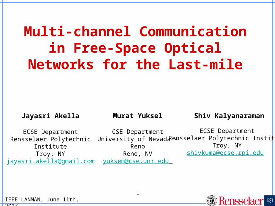
IEEE LANMAN, June 11th, 2007
1
Multi-channel Communication in Free-
Space Optical Networks for the Last-mile
Jayasri Akella
ECSE DepartmentRensselaer Polytechnic
InstituteTroy, NY
Murat Yuksel
CSE DepartmentUniversity of Nevada –
RenoReno, NV
Shiv Kalyanaraman
ECSE DepartmentRensselaer Polytechnic Institute
Troy, [email protected]
IEEE LANMAN, June 11th, 2007
2
Outline
1. Motivation
2. A Brief Introduction to Free-Space Optical Networks
3. Multi-element Optical Antennas for Broadband Access
4. Inter-Channel Interference and Array Capacity
5. Array Designs
6. Design Guidelines
IEEE LANMAN, June 11th, 2007
3
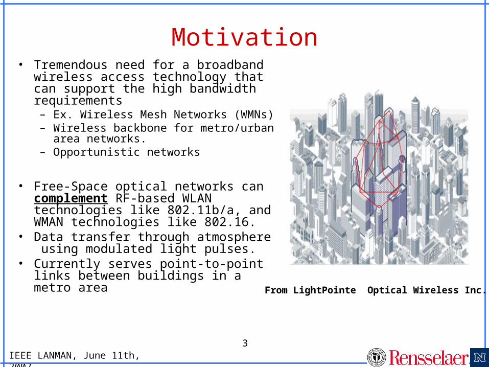
Motivation• Tremendous need for a broadband
wireless access technology that can support the high bandwidth requirements – Ex. Wireless Mesh Networks
(WMNs)– Wireless backbone for metro/urban
area networks. – Opportunistic networks
• Free-Space optical networks can complement RF-based WLAN technologies like 802.11b/a, and WMAN technologies like 802.16.
• Data transfer through atmosphere using modulated light pulses.
• Currently serves point-to-point links between buildings in a metro area
From LightPointe Optical Wireless Inc.
IEEE LANMAN, June 11th, 2007
4
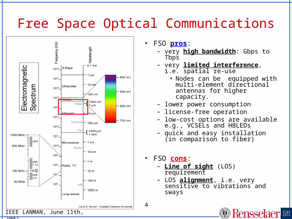
Free Space Optical Communications• FSO pros:
– very high bandwidth: Gbps to Tbps
– very limited interference, i.e. spatial re-use
• Nodes can be equipped with multi-element directional antennas for higher capacity.
– lower power consumption– license-free operation– low-cost options are available
e.g., VCSELs and HBLEDs– quick and easy installation (in
comparison to fiber)
• FSO cons:– Line of sight (LOS) requirement– LOS alignment, i.e. very
sensitive to vibrations and sways
IEEE LANMAN, June 11th, 2007
5
Typical FSO Communication System
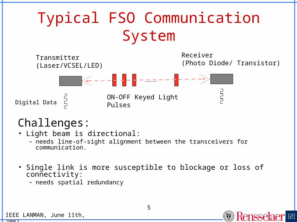
Challenges:• Light beam is directional:
– needs line-of-sight alignment between the transceivers for communication.
• Single link is more susceptible to blockage or loss of connectivity:– needs spatial redundancy
Digital DataON-OFF Keyed Light Pulses
Transmitter (Laser/VCSEL/LED)
Receiver(Photo Diode/ Transistor)
IEEE LANMAN, June 11th, 2007
6
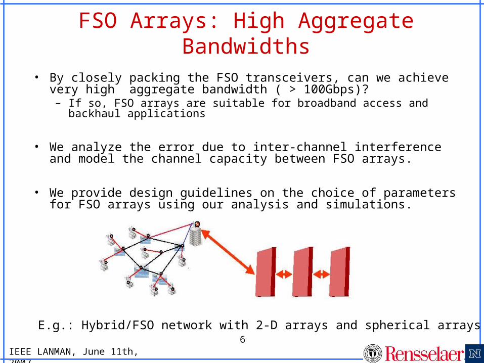
FSO Arrays: High Aggregate Bandwidths
E.g.: Hybrid/FSO network with 2-D arrays and spherical arrays
• By closely packing the FSO transceivers, can we achieve very high aggregate bandwidth ( > 100Gbps)? – If so, FSO arrays are suitable for broadband access and
backhaul applications
• We analyze the error due to inter-channel interference and model the channel capacity between FSO arrays.
• We provide design guidelines on the choice of parameters for FSO arrays using our analysis and simulations.

IEEE LANMAN, June 11th, 2007
7
Array Designs : Helical vs. Uniform Transceiver Placement
Helical array design gives more capacity for a given range and transceiver parameters due to reduced inter-channel interference.
IEEE LANMAN, June 11th, 2007
8
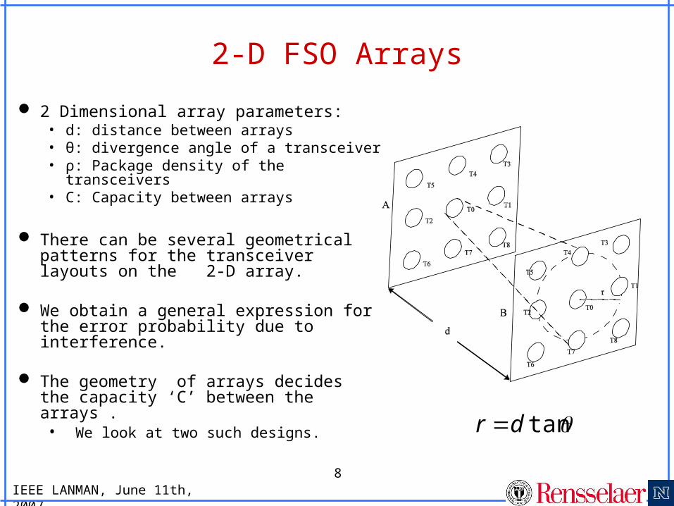
2-D FSO Arrays
2 Dimensional array parameters: • d: distance between arrays• θ: divergence angle of a transceiver• ρ: Package density of the
transceivers• C: Capacity between arrays
There can be several geometrical patterns for the transceiver layouts on the 2-D array.
We obtain a general expression for the error probability due to interference.
The geometry of arrays decides the capacity ‘C’ between the arrays .• We look at two such designs.
tandr
IEEE LANMAN, June 11th, 2007
9
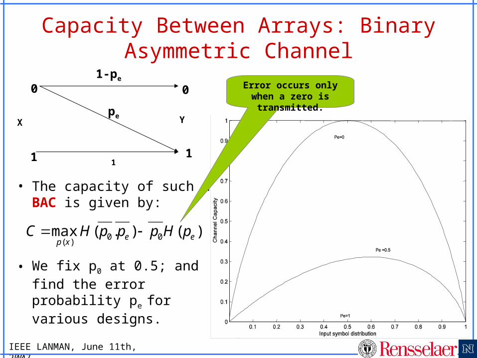
Capacity Between Arrays: Binary Asymmetric Channel
• The capacity of such a BAC is given by:
• We fix p0 at 0.5; and find the error probability pe
for various designs.
)().(max 00)(
eexp
pHpppHC
0
1
0
1
1-pe
pe
1
X Y
Error occurs only when a zero is transmitted.
IEEE LANMAN, June 11th, 2007
10
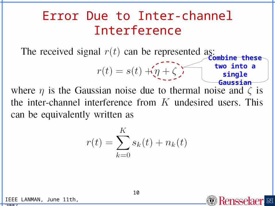
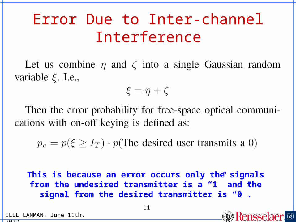
Error Due to Inter-channel Interference
Combine these two into
a single Gaussian
IEEE LANMAN, June 11th, 2007
11
Error Due to Inter-channel Interference
This is because an error occurs only the signals from the undesired transmitter is a “1” and the signal from
the desired transmitter is “0”.
IEEE LANMAN, June 11th, 2007
12
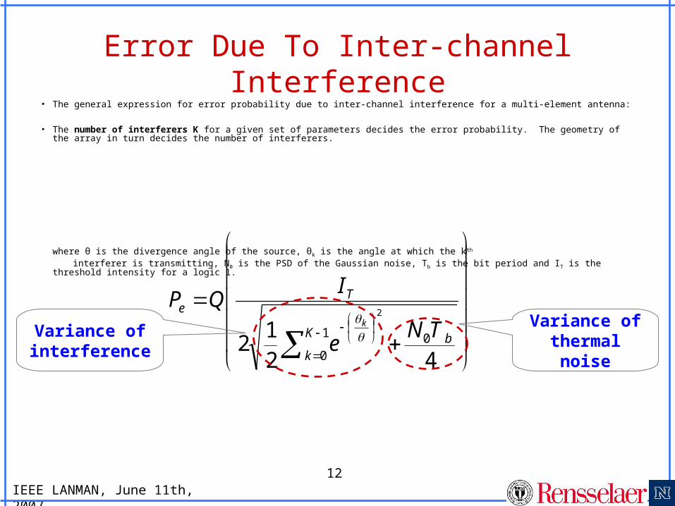
Error Due To Inter-channel Interference
• The general expression for error probability due to inter-channel interference for a multi-element antenna:
• The number of interferers K for a given set of parameters decides the error probability. The geometry of the array in turn decides the number of interferers.
where θ is the divergence angle of the source, θk is the angle at which the kth
interferer is transmitting, N0 is the PSD of the Gaussian noise, Tb is the bit period and IT is the threshold intensity for a logic 1.
421
2 01
0
2
bK
k
Te
TNe
IQP
k
Variance of
thermal noise
Variance of interference
IEEE LANMAN, June 11th, 2007
13
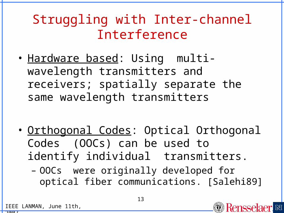
Struggling with Inter-channel Interference
• Hardware based: Using multi-wavelength transmitters and receivers; spatially separate the same wavelength transmitters
• Orthogonal Codes: Optical Orthogonal Codes (OOCs) can be used to identify individual transmitters.– OOCs were originally developed for optical
fiber communications. [Salehi89]
IEEE LANMAN, June 11th, 2007
14
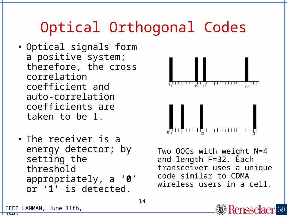
Optical Orthogonal Codes• Optical signals form
a positive system; therefore, the cross correlation coefficient and auto-correlation coefficients are taken to be 1.
• The receiver is a energy detector; by setting the threshold appropriately, a ‘0’ or ‘1’ is detected.
Two OOCs with weight N=4 and length F=32. Each transceiver uses a unique code similar to CDMA wireless users in a cell.
IEEE LANMAN, June 11th, 2007
15
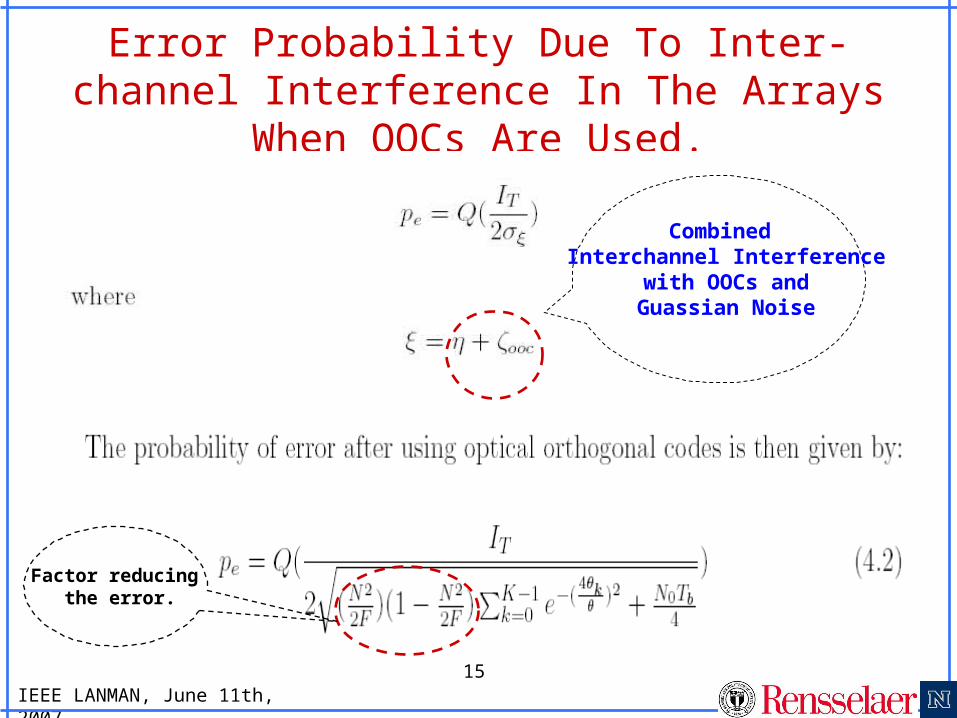
Error Probability Due To Inter-channel Interference In The Arrays When OOCs
Are Used.
Combined Interchannel Interference
with OOCs and Guassian Noise
Factor reducing the error.
IEEE LANMAN, June 11th, 2007
16
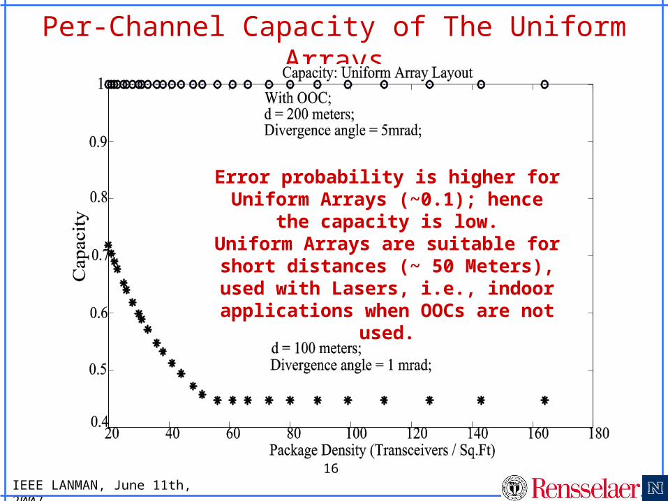
Per-Channel Capacity of The Uniform Arrays
Error probability is higher for Uniform Arrays (~0.1); hence the
capacity is low.Uniform Arrays are suitable for short distances (~ 50 Meters), used with Lasers, i.e., indoor
applications when OOCs are not used.
IEEE LANMAN, June 11th, 2007
17
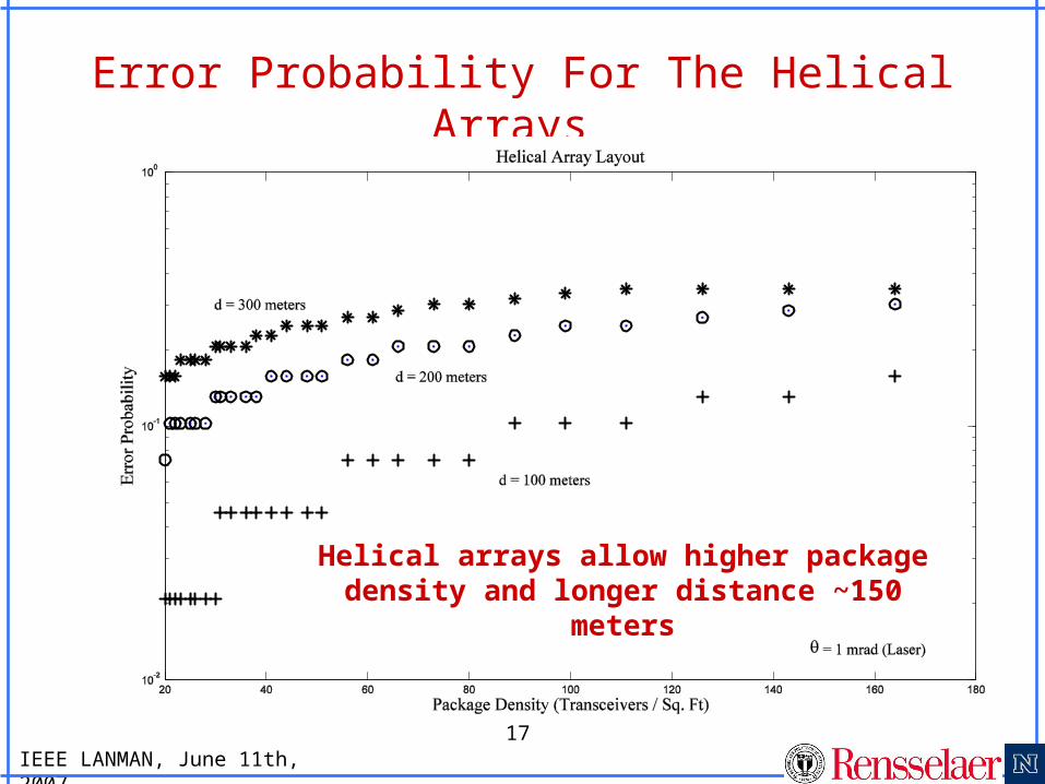
Error Probability For The Helical Arrays
Helical arrays allow higher package density and longer distance ~150 meters
IEEE LANMAN, June 11th, 2007
18
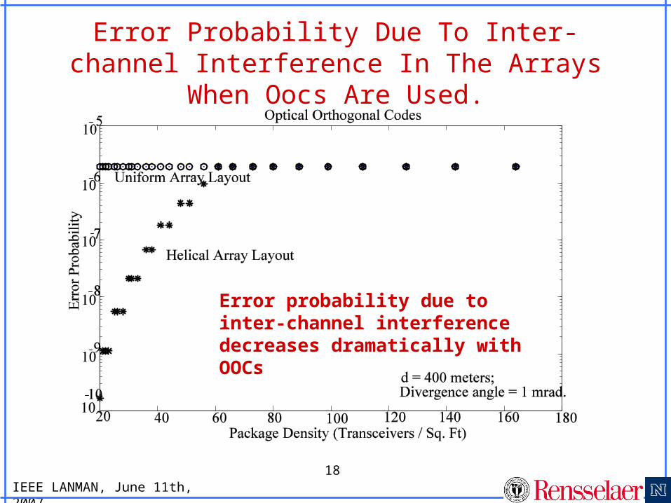
Error Probability Due To Inter-channel Interference In The Arrays When Oocs Are
Used.
Error probability due to inter-channel interference decreases dramatically with OOCs
IEEE LANMAN, June 11th, 2007
19
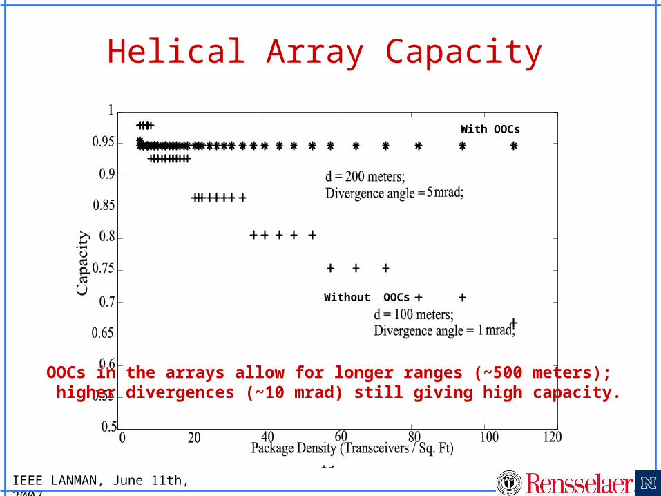
Helical Array Capacity
OOCs in the arrays allow for longer ranges (~500 meters); higher divergences (~10 mrad) still giving high capacity.
With OOCs
Without OOCs
IEEE LANMAN, June 11th, 2007
20
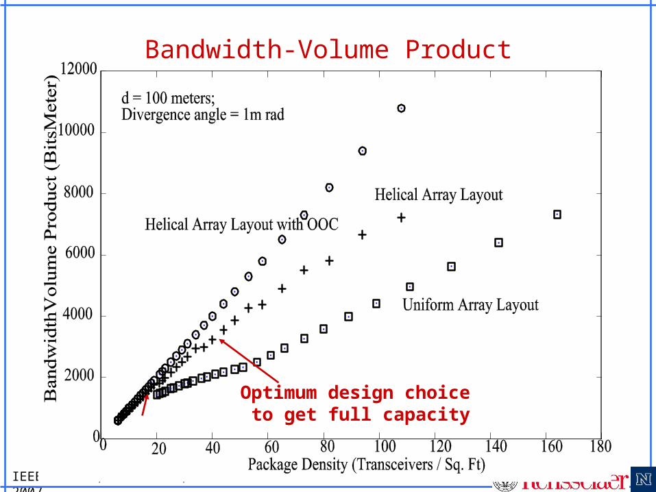
Bandwidth-Volume Product
Optimum design choice to get full capacity
IEEE LANMAN, June 11th, 2007
21
Contributions• Channel capacity between arrays is interference limited.
We derived general expressions for error probability for the arrays with and without orthogonal codes.
• Smaller the beam divergence, better is the capacity for a given range. This also means higher bandwidth.
• Non-uniform placement of transceivers allow for higher package densities of transceivers.
• With the use of OOCs we can achieve near ideal capacities for the arrays; The bandwidth for such arrays is limited only by the number of OOCs that can be implemented.
• Example: • An array with 5 channels at full capacity, each operating
at 100 Mbps, with an aggregate bandwidth of 0.5 Gbps. • Alternatively, we can pack 10 channels, each operating
at 3/4ths of its capacity and with an aggregate bandwidth of 0.75 Gbps.
• We introduce a metric that measures effectiveness of 2-D array FSO communication: “Bandwidth-Volume Product”.
IEEE LANMAN, June 11th, 2007
22
Future Work
• Spatial codes on 2-D arrays to improve FSO link reliability.
• Optimization of the location of the transceivers on the array to maximize the bandwidth.
• Analysis of multiple hops using array antennas to achieve both spatial redundancy and robustness against atmospheric adversities.
IEEE LANMAN, June 11th, 2007
23
Thank you