Embed Size (px)
Citation preview
1932-4553 (c) 2015 IEEE. Personal use is permitted, but republication/redistribution requires IEEE permission. See http://www.ieee.org/publications_standards/publications/rights/index.html for more information.
This article has been accepted for publication in a future issue of this journal, but has not been fully edited. Content may change prior to final publication. Citation information: DOI 10.1109/JSTSP.2016.2523924, IEEE Journalof Selected Topics in Signal Processing
IEEE JOURNAL OF SELECTED TOPICS IN SIGNAL PROCESSING, VOL. 10, NO. 3, 2016 1
An Overview of Signal Processing Techniques forMillimeter Wave MIMO Systems
Robert W. Heath Jr., Nuria Gonzalez-Prelcic, Sundeep Rangan, Wonil Roh, and Akbar Sayeed
Abstract—Communication at millimeter wave (mmWave) fre-quencies is defining a new era of wireless communication. ThemmWave band offers higher bandwidth communication channelsversus those presently used in commercial wireless systems. Theapplications of mmWave are immense: wireless local and personalarea networks in the unlicensed band, 5G cellular systems, notto mention vehicular area networks, ad hoc networks, and wear-ables. Signal processing is critical for enabling the next generationof mmWave communication. Due to the use of large antennaarrays at the transmitter and receiver, combined with radiofrequency and mixed signal power constraints, new multiple-input multiple-output (MIMO) communication signal processingtechniques are needed. Because of the wide bandwidths, lowcomplexity transceiver algorithms become important. There areopportunities to exploit techniques like compressed sensing forchannel estimation and beamforming. This article provides anoverview of signal processing challenges in mmWave wirelesssystems, with an emphasis on those faced by using MIMOcommunication at higher carrier frequencies.
I. INTRODUCTION
THE millimeter wave (mmWave) band is the frontier forcommercial – high volume consumer – wireless commu-
nication systems [1]. MmWave makes use of spectrum from30 GHz to 300 GHz whereas most consumer wireless systemsoperate at carrier frequencies below 6 GHz. The main benefitof going to mmWave carrier frequencies is the larger spectralchannels. For example, channels with 2 GHz of bandwidthare common for systems operating in the 60 GHz unlicensedmmWave band. Larger bandwidth channels mean higher datarates. Despite the recent interest in mmWave, the study ofmmWave is in fact as old as wireless itself. Some of thefirst experiments like those of Bose and Lebedev [2] wereperformed in the 1890s in the mmWave band.
Copyright (c) 2016 IEEE. Personal use of this material is permitted.However, permission to use this material for any other purposes must beobtained from the IEEE by sending a request to [email protected]
R. W. Heath Jr. is with The University of Texas at Austin, Austin,TX, USA (email: [email protected]). Nuria Gonzalez-Prelcic is with theUniversity of Vigo, Spain, (email: [email protected]). Sundeep Rangan iswith New York University, USA, (email: [email protected]). Wonil Roh, iswith Samsung Electronics, South Korea, (email: [email protected]).Akbar Sayeed, is with the University of Wisconsin-Madison, USA, (email:[email protected]). R. Heath would like to acknowledge support fromthe National Science Foundation under grant numbers NSF-CCF-1319556,NSF-CCF-1514275, and NSF-CCF-1527079, the U.S. Department of Trans-portation through the Data-Supported Transportation Operations and Planning(D-STOP) Tier 1 University Transportation Center, the Intel / Verizon 5Gprogram, MERL, Nokia, Huawei, and Toyota. N. Gonzalez-Prelcic would liketo acknowledge support from the Spanish Government and the European Re-gional Development Fund (ERDF) under projects TACTICA and COMPASS(TEC2013-47020-C2-1-R). A. Sayeed would like to acknowledge supportfrom the National Science Foundation under grant numbers ECCS-1247583and IIP-1444962, and the Wisconsin Alumni Research Foundation.
The first standardized consumer radios were in the 60 GHzunlicensed band. WirelessHD [3] is the name for the successfulpersonal area network (PAN) technology developed by aconsortium of companies. It is used primarily to replace cablesthat carry uncompressed high definition video. IEEE 802.11ad[4] is a wireless local area network (WLAN) standard. It wasessentially developed in the former WiGig consortium thatwas later absorbed into the WiFi Alliance. The developmentof wireless communication in the 60 GHz unlicensed bandwas the topic of tremendous amounts of research [5]–[13].The aforementioned PAN and LAN standards use about 2GHz of bandwidth and support OFDM (orthogonal frequencydivision multiplexing) or SC-FDE (single-carrier frequency-domain equalization) type modulations to provide data ratesup to 6 Gbps. Beamforming through several (up to four) smallantenna arrays is also supported. Evolutions of these standardsare expected to support more sophisticated forms of multiple-input multiple-output (MIMO) communication for higher datarates. Products based on WirelessHD have been available forseveral years while those based on IEEE 802.11ad are startingto ship in higher volumes. It seems that WLAN and PANdevices operating at 60 GHz will be the first widely deployedconsumer wireless devices at mmWave.
MmWave is also receiving tremendous interest by academia,industry, and government for 5G cellular systems [14]–[19].The main reason is that spectrum available in sub-6 GHzbands is limited. Though signal processing approaches likecognitive radio [20], [21] free more spectrum, it still is notenough if gigabit-per-second data rates are required. Initialwork has established the viability of 5G cellular throughpropagation studies and later through system capacity analysis.Surprisingly, there is much earlier work on mmWave cellularwhich proposes the integration of voice/data communicationat 60 GHz [22]. The Federal Communication Commission inthe USA is among the first to back enthusiasm behind 5G withspectrum for mobile cellular applications [19].
MmWave is already a significant footprint wireless back-haul. Traditional physical layer designs for 60 GHz back-haul assume expensive directional antennas, reducing costadvantages over wired solutions [1]. Low cost mmWavetechnologies with adaptive arrays, however, are actively beingdeveloped to backhaul densely distributed small cells in urbanenvironments. In this scenario, distances are very short butthe operating expenditures associated with using fiber opticalcable may still be prohibitive. It will be possible to establishhigh capacity connections using state-of-art, low cost mmWavedevices [23], [24]. Self-backhaul may even be possible inmillimeter wave cellular systems [25].

1932-4553 (c) 2015 IEEE. Personal use is permitted, but republication/redistribution requires IEEE permission. See http://www.ieee.org/publications_standards/publications/rights/index.html for more information.
This article has been accepted for publication in a future issue of this journal, but has not been fully edited. Content may change prior to final publication. Citation information: DOI 10.1109/JSTSP.2016.2523924, IEEE Journalof Selected Topics in Signal Processing
2 IEEE JOURNAL OF SELECTED TOPICS IN SIGNAL PROCESSING, VOL. 10, NO. 3, 2016
MmWave has other potential applications as well. Forexample, with the recent excitement related to connected andautonomous vehicles, mmWave may play a role in providinghigh data rate connections between cars. This is naturalbecause mmWave is already the backbone of automotive radar,which has been widely deployed and developed over the pastten years [26]. The combination of mmWave communicationand radar [27] is also interesting for mmWave applications.MmWave could be used to enable high rate low latencyconnections to clouds that permit remote driving of vehiclesthrough new mmWave vehicle-to-infrastructure applications.MmWave is also of interest for high speed wearable net-works that connect cell phone, smart watch, augmented realityglasses, and virtual reality headsets [28]. Clearly the future isbright for new applications of mmWave.
Signal processing is of critical importance for millimeterwave cellular systems. The reasons why signal processingis different in millimeter wave frequencies than at lowerfrequencies [29], [30] are: (i) there are new constraints onthe hardware in part due to the high frequency and bandwidthcommunication channels, (ii) the channel models are different,and (iii) large arrays will be used at both the transmitter andreceivers. These differences underly the foundations of thissurvey article.
New hardware constraints arise from practical considera-tions like power consumption and circuit technology. One sig-nal processing implication is renewed interest in partitioningsignal processing operations between analog and digital do-mains to reduce, for example, the number of analog-to-digitalconverters or their resolution. This has led to the developmentof hybrid beamforming architectures [30]–[34], beamspacesignal processing techniques [35], [36], lens-based analogbeamforming antennas [30], and low-rate ADC methods [37],[38]. Another signal processing implication is that analogcomponents like phase shifters are imperfect (quantized phaseand insertion loss). This leads to new mathematical models ofimpairments, new analyses of the effects of these impairments,and new algorithms that yield good performance even in thepresence of impairments. We identify several of the signalprocessing challenges that arise from hardware constraints inthis article.
The channel models at mmWave are different because thepropagation environment has a different effect on smallerwavelength signals [1]. For example, diffraction tends to belower due to the reduced Fresnel zone, scattering is higherdue to the increased effective roughness of materials, andpenetration losses can be much larger. Mmwave channelmodels use some common properties as low frequency systems(multi-path delay spread, angle spread, and Doppler shift),with different parameters though (few and clustered paths forexample leading to more sparsity in the channel). In addtion,some new features are introduced as well to account for highsensitivity to blockages (buildings, human body, or fingers)and strong differences between line-of-sight and non-line-of-sight propagation conditions. There are many opportunitiesto exploit the mathematical properties of sparsity in channelestimation and equalization and precoder/combiner design.
The arrays discussed for mmWave communication may be
large. Example array sizes in the literature include 16 elementsin [39] or 256 elements in [40], but the arrays may even belarger at the base station in a cellular system. IEEE 802.11adproducts with 32 elements are already commercially available.To provide sufficient link margin, in most mmWave commu-nication systems, arrays will be used at both the transmitterand receiver, creating many opportunities to apply MIMOcommunication techniques. The MIMO techniques appliedwill be different though due to the different channel character-istics and additional hardware constraints found at mmWavefrequencies. The connection between MIMO and mmWaveis the main reason that we emphasize signal processing formmWave MIMO systems.
The combined implications of hardware constraints, channelmodels, and large arrays has a far-reaching impact on thedesign of mmWave communication systems. For example,mmWave cellular systems might have new architectural fea-tures. For example, devices might maintain active connectionswith multiple base stations to achieve diversity from building,human, or self-body blockages. Relays and cooperative diver-sity, which have not been a huge success in lower frequencycellular networks, may play a more important role in improv-ing coverage in mmWave cellular systems. Many challengesremain in both designing new systems to support mmWavecommunication and devising algorithms so that mmWave canachieve its best performance in such systems.
The purpose of this article is to provide an overview ofthe state-of-the-art in signal processing for mmWave wire-less communication systems. Section II explains the differ-ent channel characteristics at mmWave compared to lowerfrequency systems. Understanding these characteristics is es-sential for the design of suitable MIMO architectures andsignal processing algorithms. Section III describes the mainmmWave MIMO architectures which have been proposed toaccount for mmWave hardware constraints and channel char-acteristics. The different approaches described include analogbeamforming, hybrid precoding and combining, and one-bitarchitectures. A detailed review of beamtraining protocolsand channel estimation algorithms is provided in SectionV. Approaches include both codebook-based strategies andcompressed channel sensing approaches, and threshold basedmethods, illustrating approaches that operate under differentassumptions. Precoding and combining algorithms for thedifferent mmWave MIMO architectures are introduced inSection IV. The objective is to provide some signal processingexamples about how MIMO precoders and combiners can beconfigured in mmWave systems. The paper concludes withsome final remarks in Section VI.
Notation: We use the following notation throughout thispaper: bold lowercase a is used to denote column vectors,bold uppercase A is used to denote matrices, non-bold lettersa,A are used to denote scalar values, and caligraphic lettersA to denote sets. Using this notation, |a| is the magnitudeof a scalar, ‖a‖ is the `2 norm, ‖a‖0 is the `0 norm, ‖A‖Fis the Frobenius norm, σk(A) denotes the kth singular valueof A in decreasing order, tr(A) denotes the trace, A∗ is theconjugate transpose, AT is the matrix transpose, A−1 denotesthe inverse of a square matrix, [a]k is the kth entry of a, |A|

1932-4553 (c) 2015 IEEE. Personal use is permitted, but republication/redistribution requires IEEE permission. See http://www.ieee.org/publications_standards/publications/rights/index.html for more information.
This article has been accepted for publication in a future issue of this journal, but has not been fully edited. Content may change prior to final publication. Citation information: DOI 10.1109/JSTSP.2016.2523924, IEEE Journalof Selected Topics in Signal Processing
HEATH et al.: AN OVERVIEW OF SIGNAL PROCESSING TECHNIQUES FOR MILLIMETER WAVE MIMO SYSTEMS 3
is the cardinality of set A. A⊗B is the Kronecker product ofA and B. We use the notation N (m,R) to denote a complexcircularly symmetric Gaussian random vector with mean mand covariance R. We use E to denote expectation.
II. MILLIMETER WAVE PROPAGATION AND CHANNELMODELS
Propagation aspects are unique at mmWave due to thevery small wavelength compared to the size of most ofthe objects in the environment. Understanding these channelcharacteristics is fundamental to developing signal processingalgorithms for mmWave transmitter and receivers.
A. Distance-based path loss
For free-space propagation, the transmit power, Pt, and far-field receive power, Pr, are related by Friis’ Law [41],
Pr = GrGt
(λ
4πd
)2
Pt, (1)
where the powers are in linear scale, d is the TX-RX separationdistance, λ is the wavelength and Gt and Gr are the transmitand receive antenna gains. Friis’ Law implies that the isotropicpath loss (i.e. the ratio Pt/Pr with unity antenna gains Gr =Gt = 1), increases inversely with the wavelength squared,λ−2. This fact implies that, in absence of directional antennagains, mmWave propagation will experience a higher pathloss relative to conventional lower frequencies. For a givenphysical antenna aperture, however, the maximum directionalgains generally scale as Gr, Gt ∝ λ−2, since more antennaelements can be fit into the same physical area. Therefore,the scaling of the antenna gains more than compensates forthe increased free-space path-loss at mmWave frequencies.Compensating for path loss in this manner will require, how-ever, directional transmissions with high-dimensional antennaarrays – explaining how MIMO is a defining characteristic ofmmWave communication.
While free space propagation can be predicted by Friis’Law, the path loss in general environments depend on theparticular position of objects that can attenuate, diffract andreflect signals. Ray tracing has been reasonably successfulin predicting site-specific mmWave propagation, particularlyin indoor settings, for at least a decade [42], [43]. There isalso a large body of work in developing mmWave statisticalmodels that describe the distribution of path losses over anensemble of environments [44], [45], with a particularly largenumber of studies in short-range links in wireless PAN orindoor LAN systems [5], [6], [46]–[50]. The most commonstatistical model describes the average path loss (not includingsmall-scale fading) via a linear model of the form
PL(d) [dB] = α+ 10β log10(d) + ξ, ξ ∼ N (0, σ2), (2)
where d is the distance, α and β are linear model parametersand ξ is a lognormal term accounting for variances in shad-owing. When converting to dB scale, Friis’ formula (1) is aspecial case of the model (2) with β = 2. Parameters for themodel (2) can be found in [5], [6], [46]–[50] for short-rangeand indoor settings.
More recent work has focused on path loss models forlonger range outdoor links to assess the feasibility of mmWavepicocellular networks, including measurements in New YorkCity [15], [51], [52]. A surprising consequence of these studiesis that, for distances of up to 200 m from a potential low-powerbase station or access point (similar to cell radii in currentmicro- and pico-cellular deployments), the distance-based pathloss in mmWave links is no worse than conventional cellularfrequencies after compensating for the additional beamforminggain. It was these findings that suggested the mmWave bandsmay be viable for picocellular deployments and generatedconsiderable interest in mmWave cellular systems [14], [53].At the same time, the results also show that, should mmWavefrequencies be employed in cellular networks, directionaltransmissions, adaptive beamforming, and other MIMO tech-niques will be of central importance.
B. Blocking and outageWhile the distance-based path loss of mmWave frequencies
can be theoretically compensated by directional transmissions,a more significant challenge is their severe vulnerability toblockage. Materials such as brick can attenuate mmWavesignals by as much as 40 to 80 dB [14], [47], [54]–[56] andthe human body itself can result in a 20 to 35 dB loss [57].Foliage loss can also be significant [58], [59]. Alternatively,humidity and rain fades, common problems for long rangemmWave backhaul links [60], are not an issue in either short-range indoor links or micro-cellular systems [15], [61] withsub-km link distances.
The human body (depending on the material of the clothing)and most building materials are reflective. This allows themto be important scatterers to enable coverage via NLOS pathsfor cellular systems [50], [56]. For example, measurementsin New York City [15] confirm that even in extremely denseurban environments, coverage is possible up to 200 m from apotential cell site. This is good because diffraction – a primarymeans of coverage in sub 6 GHz systems – is not significantat mmWave frequencies.
To quantify the effect of blocking, cellular system evaluationcan use a two-state model (LOS and NLOS) or a three statemodel (LOS, NLOS, and signal outage). The probability ofa link being in each state is a function of distance. Usingthe NYC measurements in [15], [16] fits statistical models forthis three state model, similar in form to some LOS-NLOSprobabilities used in 3GPP LOS-NLOS for heterogeneousnetworks [62].
Blocking models can also be derived analytically fromrandom shape theory [63] or from geographic information[64]. Using such models, it is possible to evaluate coverageand capacity in mmWave cellular networks analytically usingstochastic geometry [18].
A major outstanding issue is characterizing the joint proba-bilities in outage between links from different cells, which iscritical in assessing the benefits of macro-diversity [65], [66].
C. Spatial characteristics and multipath channel modelsThe mmWave MIMO channel can be described with stan-
dard multipath models used in lower frequencies [67]. Con-
1932-4553 (c) 2015 IEEE. Personal use is permitted, but republication/redistribution requires IEEE permission. See http://www.ieee.org/publications_standards/publications/rights/index.html for more information.
This article has been accepted for publication in a future issue of this journal, but has not been fully edited. Content may change prior to final publication. Citation information: DOI 10.1109/JSTSP.2016.2523924, IEEE Journalof Selected Topics in Signal Processing
4 IEEE JOURNAL OF SELECTED TOPICS IN SIGNAL PROCESSING, VOL. 10, NO. 3, 2016
sider a MIMO system with Nt transmit and Nr receive anten-nas. For 2D channel models, the transmit and receive antennaarrays are described by their array steering vectors, aT(θT)and aR(θR) representing the array phase profile as a functionof angular directions θR and θT of arriving or departing planewaves. For an N -element uniform linear array (ULA), thesteering vector is given by
a(θ) =[1, e−j2πϑ, e−j4πϑ, · · · , e−j2πϑ(N−1)
]T(3)
where the normalized spatial angle ϑ is related to the physicalangle (of arrival or departure) θ ∈ [−π/2, π/2] as ϑ =dλ sin(θ), d denotes the antenna spacing and λ denotes thewavelength of operation. Typically, d = λ/2. In 3D channelmodels — which are critical for mmWave arrays — thesteering vectors are functions a(θ, φ) = aaz(θ) ⊗ ael(φ) ofboth the horizontal (azimuth) angle θ and elevation angle φ(with the corresponding normalized elevation angle denotedby ϕ). Given the steering vectors, the MIMO channel can bedescribed by a multi-path model (see, e.g, [36], [67], [68]) ofthe form
y(t) =
Np∑`=1
α`ej2πν`taR(θR,`, φR,`)aT
∗(θT,`, φT,`)x(t− τ`)
+ v(t), (4)
where x(t) is the transmitted signal vector, y(t) is the receivedsignal vector, v(t) is the noise vector, and Np is the numberof paths. Each path ` is described by five parameters: Its angleof arrival pair (θR,`, φR,`), angle of departure pair (θT,`, φT,`),delay τ`, complex gain α` and Doppler shift ν`. The Dopplershift is determined by the angle of arrival or departure relativeto the motion of the receiver or transmitter.
It is often useful to represent the channel in the frequencydomain. In general, the channel response is time-varying
H(t, f) =
Np∑`=1
α`ej2π(ν`t−τ`f)aR(θR,`, φR,`)aT
∗(θT,`, φT,`).
(5)Suppose that the channel is sufficiently slowly varying overthe sigal duration of interest T , that is, the Doppler shifts ofall the paths are small, ν`T � 1 ∀`, ` = 1, . . . , Np. Then, (5)can approximately be expressed as
H(f) =
Np∑`=1
α`e−j2πτ`faR(θR,`, φR,`)aT
∗(θT,`, φT,`). (6)
If in addition, the bandwidth of the channel W is sufficientlysmall so that τ`W � 1 ∀`, ` = 1, . . . , Np then we get thenarrowband spatial model for the channel matrix
H =
Np∑`=1
α`aR(θR,`, φR,`)aT∗(θT,`, φT,`). (7)
Statistical MIMO models used for system simulation typi-cally describe the paths as arriving in “clusters”, where eachcluster has some distribution on the delay, power, and centralangles of arrival and departure. Physically, the path clusterscorrespond to different macro-level paths, and the angle and
delay spreads within each cluster capture the scattering fromdiffuse reflections along those paths. MmWave indoor mea-surements such as [6], [69] have demonstrated large numbersof such path clusters due to reflections from office materials.Measurements in New York City [15] have shown that NLOSoutdoor links can similarly exhibit several dominant clusters.The parameters for statistical multipath models derived fromsuch measurements can be found in [70] for 802.11ad systems,and [16], which uses the measurements in [15] to derive sta-tistical multipath models similar to the 3GPP cellular modelsin [62], [71].
While the above models describe the average statistics ofthe path loss, one major outstanding issue is the modelingof channel variability. Since mmWave signals can be blockedby many materials, the path clusters can rapidly appear anddisappear, with significant impact on channel tracking. Someinitial stochastic models for temporal variability have appearedin [72].
D. Beamspace (virtual) system representation
The highly directional nature of propagation and the highdimensionality of MIMO channels at mmWave frequenciesmakes beamspace representation of MIMO systems a nat-ural choice. The antenna space and beamspace are relatedthrough a spatial Fourier transform [30], [31], [36], [68].We describe the beamspace representation of a 1D arrayconsisting of an N dimensional ULA (extension to 2D arraysare straightforward; see, e.g. [31], [73]). The beamspace (vir-tual) representation corresponds to system representation withrespect to uniformly spaced spatial angles ϑi = i∆ϑ = i/N ,i = 0, · · · , N − 1. The corresponding steering vectors definedby {θi = arcsin(λϑi/d)} result in an orthonormal basis forthe spatial signal space. In particular, the N ×N matrix
U =1√N
[a(θ0), · · · ,a(θ1), · · · ,a(θN−1)]T (8)
is a unitary DFT matrix: U∗U = UU∗ = I. The beamspacesystem representation is given by
Yb(f) ≈ Hb(t, f)Xb(f) + Vb(f)
yb(t) = U∗Ry(t) ; xb(t) = U∗Tx(t) ; vb(t) = U∗Rv(t) (9)Hb(t, f) = U∗RH(t, f)UT .
which is unitarily equivalent to the antenna domain repre-sentation using the transfer function in (5). In particular, thesparse/low-rank nature of the MIMO channel at mmWaveis explicitly reflected in the sparse nature of the beamspacechannel matrix Hb(t, f).
For a narrowband MIMO system, the beamspace channelrepresentation can be explicitly expressed as [35], [36]
H = URHbU∗T =
Nr∑i=1
Nt∑k=1
[Hb]i,kaR(θR,i)aT∗(θT,k) (10)
where {θR,i} and {θT,k} are virtual AoAs and AoDs corre-sponding to the uniformly spaced normalized angles {ϑR,i}and {ϑT,k}. The concept of beamspace channel representationis intuitive and easy to understand for the narrowband case. It
1932-4553 (c) 2015 IEEE. Personal use is permitted, but republication/redistribution requires IEEE permission. See http://www.ieee.org/publications_standards/publications/rights/index.html for more information.
This article has been accepted for publication in a future issue of this journal, but has not been fully edited. Content may change prior to final publication. Citation information: DOI 10.1109/JSTSP.2016.2523924, IEEE Journalof Selected Topics in Signal Processing
HEATH et al.: AN OVERVIEW OF SIGNAL PROCESSING TECHNIQUES FOR MILLIMETER WAVE MIMO SYSTEMS 5
can be extended to time- and frequency-selective channels aswell via uniform sampling in delay and Doppler commensuratewith the signaling bandwidth W and duration T [35], [68]:
H(t, f) =
Nr∑i=1
Nt∑k=1
L−1∑`=0
M2∑
m=−M2
Hb(i, k, `,m)aR(θR,i)aT∗(θT,k)
× ej2πmT te−j2π
`W f , (11)
H(f) =
Nr∑i=1
Nt∑k=1
L−1∑`=0
Hb(i, k, `)aR(θR,i)aT∗(θT,k)e−j2π
`W f ,
(12)
where rather than the actual physical delay and Dopplershifts, the channel is represented by uniformly spaced delaysτ` = `/W and Doppler shifts νm = m/T with spacings∆τ = 1/W and ∆ν = 1/T . L = dWτmaxe + 1 andM = dTνmaxe. We note that due to critical sampling in angle,delay, and Doppler, the channel representations in (10), (11),and (12) represent multi-dimensional Fourier series expansionswith respect to orthogonal Fourier basis functions in angle,delay, Doppler [68].
The wideband channel model needs to be further extended ifthe number of antennas and/or the signal bandwidth becomessufficiently large [74]. For wideband operation, in general, thespatial angles θR,` and θT,` in the arguments of the steeringvectors also include a frequency dependence called beam-squint, that can result in significant degradation in performance[74], [75]. Beam squint is a significant problem for paths forwhich the dispersion factor Nαθ` ≥ 0.2 (as applied to thetransmit or receive side). A simple multi-beam solution to thebeamsquint problem is proposed in [74]. If this dispersionfactor is sufficiently small for all angles within the angularspread, then the frequency dependence of θ(f) can be ignored.
E. Beamspace channel sparsity: Low-dimensional communi-cation subspace
Consider a channel that is non-selective in time and fre-quency, H(t, f) ≈ H, to focus on its spatial structure. Letσ2c = tr(H∗H) = tr(H∗bHb) =
∑`,m |[Hb]`,m|2 denote
the channel power. For a given channel realization, the low-dimensional communication subspace is captured by the SVDof H = UΣV∗ We define the effective channel rank, peff,as the number of singular values that capture most of channelpower:
∑peffi=1 σ
2i (H) ≥ ησ2
c , for some η close to 1 (e.g., 0.8 or0.9). Optimal communication over the peff-dimensional com-munication subspace is achieved through the correspondingsingular vectors in V and U.
In sparse beamspace MIMO channels, the low-dimensionalcommunication subspace is accessed through Fourier basisvectors that serve as approximate singular vectors for thespatial signal space [30], [31], [76], [77]. The channel power isconcentrated in a low-dimensional sub-matrix of Hb, denotedHb, consisting of dominant entries indexed by the channelbeam masks:M = {(`,m) : |[Hb]`,m|2 ≥ γ max
(`,m)|[Hb]`,m|2} ;
Mr = {` : (`,m) ∈M} , Mt = {m : (`,m) ∈M)} ,(13)
where γ ∈ (0, 1) is a threshold, M is the channel beammask, andMt andMr denote the transmit and receive masksof dominant beams. The sub-matrix Hb is then defined as:Hb = [[Hb]]`,m]`∈Mr,m∈Mt
. The low-complexity beamspaceMIMO transceivers access the low-dimensional communica-tion subspace by selecting the |Mt| � Nt transmit beamsin Mt and |Mr| � Nr receive beams in Mr. We note thatmin(|Mt|, |Mr|) ≈ peff and the performance of these low-dimensional transceivers can be made arbitrarily close to theoptimal SVD-based receiver by choosing the threshhold γ in(13) sufficiently small so that Hb captures most of the channelpower. This discussion applies to deterministic channels. Forrandom multipath variations, M, Mt and Mr can be definedby replacing |[Hb]`,m|2 with E|[Hb]`,m|2.
F. Extended virtual representation for the narrowband channelmodel
When any array geometry is considered we can formulatean alternative beamspace representation of the channel, that wewill call extended virtual representation. It is written in termsof more general dictionaries instead of the basis functions forthe DFT.
Consider the multipath narrowband channel model in (7).H can be written in a more compact way as
H = ARHbA∗T, (14)
where AT ∈ CNt×Np and AR ∈ CNr×Np contain the arrayresponse vectors for the transmitter and receiver respectively,and Hb = diag(α), with α = [α1, α2, . . . , αNp ]. If we assumethat the AoAs/AoDs are taken from a uniform grid of size G,i.e. θT,`, θR,` ∈ {0, 2π
G , . . . ,2π(G−1)
G }, with G � Np, we candefine the array response matrices, whose columns are thearray response vectors corresponding to the angles in the grid,as AT, AR. Using these matrices, H can be approximated interms of a Np-sparse matrix Hb ∈ CG×G, with Np non zeroelements in the positions corresponding to the AoAs and AoDs
H = ARHbA∗T. (15)
There is grid error in (15), since the DoAs/DoDs do notnecessarily fall to the uniform grid. If the grid size is largeenough this error is usually neglected.
III. MIMO ARCHITECTURES FOR MMWAVECOMMUNICATIONS
MIMO technology has already been standardized and iswidely used in current commercial WLAN (IEEE 802.11n/ac)and cellular (IEEE 802.16e/m, 3GPP cellular LTE, and LTEAdvanced) systems at sub-6GHz frequencies [78], [79]. Thesestandards support a small number of antennas (up to a max-imum of eight, although two is commonly used). The arraysused at mmWave tend to have more elements than lowerfrequency systems (32 to 256 elements are common), but stilloccupy a small physical size due to the small wavelength.
There are important architectural differences betweenMIMO communication at sub-6GHz frequencies and atmmWave frequencies. At lower frequencies, all the signalprocessing action happens in the baseband, as illustrated in
1932-4553 (c) 2015 IEEE. Personal use is permitted, but republication/redistribution requires IEEE permission. See http://www.ieee.org/publications_standards/publications/rights/index.html for more information.
This article has been accepted for publication in a future issue of this journal, but has not been fully edited. Content may change prior to final publication. Citation information: DOI 10.1109/JSTSP.2016.2523924, IEEE Journalof Selected Topics in Signal Processing
6 IEEE JOURNAL OF SELECTED TOPICS IN SIGNAL PROCESSING, VOL. 10, NO. 3, 2016
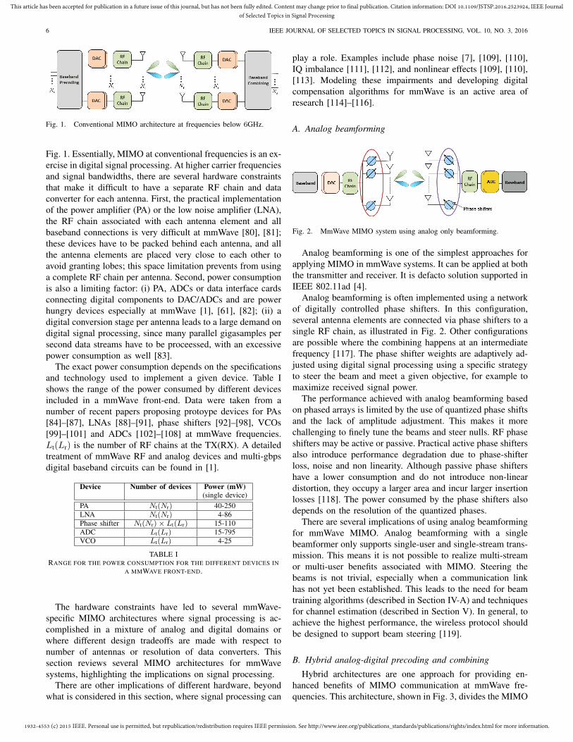
Fig. 1. Conventional MIMO architecture at frequencies below 6GHz.
Fig. 1. Essentially, MIMO at conventional frequencies is an ex-ercise in digital signal processing. At higher carrier frequenciesand signal bandwidths, there are several hardware constraintsthat make it difficult to have a separate RF chain and dataconverter for each antenna. First, the practical implementationof the power amplifier (PA) or the low noise amplifier (LNA),the RF chain associated with each antenna element and allbaseband connections is very difficult at mmWave [80], [81];these devices have to be packed behind each antenna, and allthe antenna elements are placed very close to each other toavoid granting lobes; this space limitation prevents from usinga complete RF chain per antenna. Second, power consumptionis also a limiting factor: (i) PA, ADCs or data interface cardsconnecting digital components to DAC/ADCs and are powerhungry devices especially at mmWave [1], [61], [82]; (ii) adigital conversion stage per antenna leads to a large demand ondigital signal processing, since many parallel gigasamples persecond data streams have to be proceessed, with an excessivepower consumption as well [83].
The exact power consumption depends on the specificationsand technology used to implement a given device. Table Ishows the range of the power consumed by different devicesincluded in a mmWave front-end. Data were taken from anumber of recent papers proposing protoype devices for PAs[84]–[87], LNAs [88]–[91], phase shifters [92]–[98], VCOs[99]–[101] and ADCs [102]–[108] at mmWave frequencies.Lt(Lr) is the number of RF chains at the TX(RX). A detailedtreatment of mmWave RF and analog devices and multi-gbpsdigital baseband circuits can be found in [1].
Device Number of devices Power (mW)(single device)
PA Nt(Nr) 40-250LNA Nt(Nr) 4-86Phase shifter Nt(Nr)× Lt(Lr) 15-110ADC Lt(Lr) 15-795VCO Lt(Lr) 4-25
TABLE IRANGE FOR THE POWER CONSUMPTION FOR THE DIFFERENT DEVICES IN
A MMWAVE FRONT-END.
The hardware constraints have led to several mmWave-specific MIMO architectures where signal processing is ac-complished in a mixture of analog and digital domains orwhere different design tradeoffs are made with respect tonumber of antennas or resolution of data converters. Thissection reviews several MIMO architectures for mmWavesystems, highlighting the implications on signal processing.
There are other implications of different hardware, beyondwhat is considered in this section, where signal processing can
play a role. Examples include phase noise [7], [109], [110],IQ imbalance [111], [112], and nonlinear effects [109], [110],[113]. Modeling these impairments and developing digitalcompensation algorithms for mmWave is an active area ofresearch [114]–[116].
A. Analog beamforming
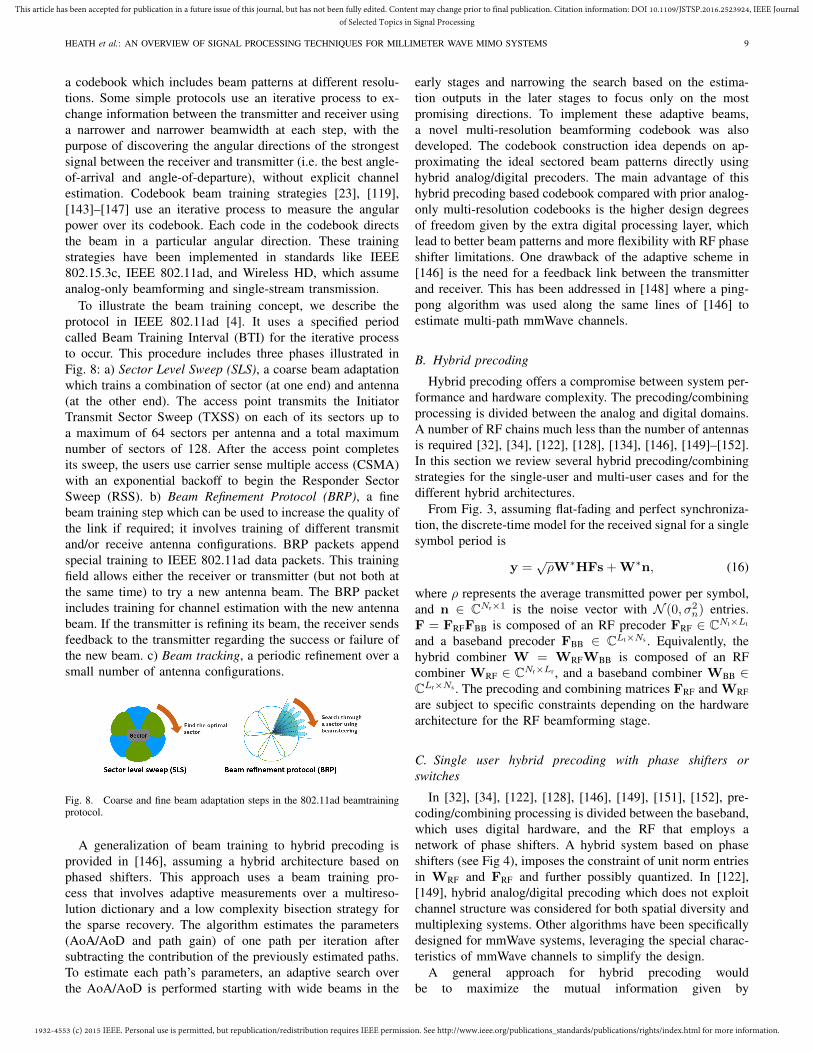
Fig. 2. MmWave MIMO system using analog only beamforming.
Analog beamforming is one of the simplest approaches forapplying MIMO in mmWave systems. It can be applied at boththe transmitter and receiver. It is defacto solution supported inIEEE 802.11ad [4].
Analog beamforming is often implemented using a networkof digitally controlled phase shifters. In this configuration,several antenna elements are connected via phase shifters to asingle RF chain, as illustrated in Fig. 2. Other configurationsare possible where the combining happens at an intermediatefrequency [117]. The phase shifter weights are adaptively ad-justed using digital signal processing using a specific strategyto steer the beam and meet a given objective, for example tomaximize received signal power.
The performance achieved with analog beamforming basedon phased arrays is limited by the use of quantized phase shiftsand the lack of amplitude adjustment. This makes it morechallenging to finely tune the beams and steer nulls. RF phaseshifters may be active or passive. Practical active phase shiftersalso introduce performance degradation due to phase-shifterloss, noise and non linearity. Although passive phase shiftershave a lower consumption and do not introduce non-lineardistortion, they occupy a larger area and incur larger insertionlosses [118]. The power consumed by the phase shifters alsodepends on the resolution of the quantized phases.
There are several implications of using analog beamformingfor mmWave MIMO. Analog beamforming with a singlebeamformer only supports single-user and single-stream trans-mission. This means it is not possible to realize multi-streamor multi-user benefits associated with MIMO. Steering thebeams is not trivial, especially when a communication linkhas not yet been established. This leads to the need for beamtraining algorithms (described in Section IV-A) and techniquesfor channel estimation (described in Section V). In general, toachieve the highest performance, the wireless protocol shouldbe designed to support beam steering [119].
B. Hybrid analog-digital precoding and combining
Hybrid architectures are one approach for providing en-hanced benefits of MIMO communication at mmWave fre-quencies. This architecture, shown in Fig. 3, divides the MIMO

1932-4553 (c) 2015 IEEE. Personal use is permitted, but republication/redistribution requires IEEE permission. See http://www.ieee.org/publications_standards/publications/rights/index.html for more information.
This article has been accepted for publication in a future issue of this journal, but has not been fully edited. Content may change prior to final publication. Citation information: DOI 10.1109/JSTSP.2016.2523924, IEEE Journalof Selected Topics in Signal Processing
HEATH et al.: AN OVERVIEW OF SIGNAL PROCESSING TECHNIQUES FOR MILLIMETER WAVE MIMO SYSTEMS 7
optimization process between analog and digital domains. Asmall number of transceivers are assumed (2 to 8), so thatNs < Lt < Nt and Nr > Lr > Ns. Assuming that Ns > 1, thenthe hybrid approach allows spatial multiplexing and multiuserMIMO to be implemented; analog beamforming is a specialcase when Ns = Lt = Lr = 1. WirelessHD described theapplication of a hybrid architecture [3], but to our knowledgeit has not yet been commercialized. Hybrid architectures wereinvestigated at lower frequencies in [120]–[122]. The generalconcept of hybrid precoding introduced in this prior work canalso be applied to mmWave systems. The algorithms for thedesign of the precoders/combiners described in these papersuse however channel models that do not fully capture the effectof limited mmWave scattering and large arrays. While thosealgorithms can be used at mmWave frequencies, further sim-plifications occur when the sparsity of the mmWave channelis leveraged. A comparison of performance and complexityof specific mmWave hybrid precoding schemes and generalhybrid precoding algorithms is a topic of current research.
Fig. 3. MIMO architecture at mmWave based on hybrid analog-digitalprecoding and combining.
The RF precoding/combining stage can be implementedusing different analog approaches like phase shifters [123],[124], switches [125] or lenses. Two hybrid structures arepossible [34]. In the first one, all the antennas can connectto each RF chain (as illustrated in Fig. 4(a)). In the secondone (see Fig. 4(b)), the array can be divided into subarrays,where each subarray connects to its own individual transceiver.Having multiple subarrays reduces hardware complexity at theexpense of less overall array flexibility. A complete analysisof the energy efficiency and spectrum-efficieny of both ar-chitectures is provided in [34]. Massive hybrid architecturesbased on the subarray structure are analyzed in [80]. Someprototypes for hybrid mmWave MIMO systems are also beingdeveloped [17], [39], [126].
Two different realizations of the hybrid architecture are il-lustrated in Fig. 4. A hybrid precoder/combiner based on phaseshifters would normally use digitally controlled phase shifterswith a small number of quantized phases. An advantage ofthe hybrid approach is that the digital precoder/combiner cancorrect for lack of precision in the analog, for example tocancel residual multi-stream interference. This allows hybridprecoding to approach the performance of the unconstrainedsolutions [32], [33]. Hybrid precoding is a topic of substantialcurrent research [29], [127]–[131].
An alternative mmWave hybrid architecture that makes useof switching networks [132], [133] with small losses [125] hasbeen recently proposed [134], to further reduce complexityand power consumption of the hybrid architecture based onphase shifters. This architecture, illustrated in Fig. 5, exploitsthe sparse nature of the mmwave channel by implementing a
(a) (b)
Fig. 4. Analog processing for hybrid beamforming based on phase shifters:(a) each RF chain is connected to all the antennas; (b) each RF chain isconnected to a subset of antennas.
compressed spatial sampling of the received signal. The analogcombiner design is performed by a subset antenna selectionalgorithm instead of an optimization over all quantized phasevalues. Every switch can be connected to all the antennas ifthe array size is small or to a subset of antennas for largerarrays.
(a) (b)
Fig. 5. Analog processing for hybrid beamforming based on switches: (a)each RF chain can be connected to all the antennas; (b) each RF chain canbe connected to a subset of antennas.
Fig. 6. The CAP-MIMO transceiver that uses a lens-based front-end for analogbeamforming; it maps the p = Ns precoded data streams to L = O(p) beams viathe mmWave beam selector and lens.
Analog beamforming for Ns > 1 in the hybrid architecturecan also be realized using a lens antenna at the front-end, usingthe fundamental fact that lenses compute a spatial Fouriertransform thereby enabling direct channel access in beamspace[30], [31]. This continuous aperture phased (CAP) MIMOtransceiver architecture is illustrated in Fig. 6 and suggestsa practical pathway for realizing high dimensional MIMOtransceivers at mmWave frequencies with significantly lowhardware complexity compared to conventional approachesbased on digital beamforming. The antennas and RF pre-coder/combiner in Fig. 3 are replaced by the continuous-aperture lens antenna and mmWave beam selector in Fig. 6.CAP-MIMO directly samples in beamspace via an array offeed antennas arranged on the focal surface of the lens antenna.
CAP-MIMO enables direct access to the beamspace channelmatrix Hb; see (9); in particular, lens-based front-end rep-resents an analog realization of the beamforming matrix U.

1932-4553 (c) 2015 IEEE. Personal use is permitted, but republication/redistribution requires IEEE permission. See http://www.ieee.org/publications_standards/publications/rights/index.html for more information.
This article has been accepted for publication in a future issue of this journal, but has not been fully edited. Content may change prior to final publication. Citation information: DOI 10.1109/JSTSP.2016.2523924, IEEE Journalof Selected Topics in Signal Processing
8 IEEE JOURNAL OF SELECTED TOPICS IN SIGNAL PROCESSING, VOL. 10, NO. 3, 2016
With a properly designed front-end, different feed antennasexcite (approximately) orthogonal spatial beams that span thecoverage area [30]. The number of ADC/DAC modules andtransmit/receive chains tracks the number of data streamsNs = p, as in the phase-array-based hybrid transceiver, asopposed to the number of antennas Nt/Nr in the conven-tional massive MIMO architecture. However, the mapping ofthe Ns (precoded) data streams into corresponding beams isaccomplished via the mmWave beam selector that maps themmWave signal for a particular data stream into a feed antennarepresenting the corresponding beam. The wideband lens canbe designed in a number of efficient ways, including a discretelens array (DLA) for lower frequencies or a dielectric lens athigher frequencies [30].
There are many implications of using a hybrid archi-tecture for mmWave MIMO. Given channel state informa-tion, new algorithms are needed to design the separate pre-coders/combiners since they decompose into products of ma-trices with different constraints (see Section IV-B and SectionIV-D for more information). Learning the channel state is alsoharder, since training data is sent through analog precodersand combiners (see Section V). More challenges are foundwhen going to broadband channels as the analog processingis (ideally) frequency flat while the digital processing can befrequency selective. There are many opportunities for futureresearch into designing cellular or local area networks aroundsupport for hybrid architectures.
C. Low resolution receivers
An alternative to analog and hybrid architectures at thereceiver is to reduce the resolution and thus power consump-tion of the ADCs to a few or as little as one bit. Thisleads to a different approach as illustrated in Fig. 7, wherea pair of low resolution ADCs are used to sample the in-phase and quadrature components of the demodulated signalat the output of each RF chain. This makes a tradeoff betweenhaving more RF chains and fewer power hungry ADCs. Thecase of a one-bit ADC is especially interesting as it hasnegligible power consumption compared to other componentsin the front-end (a one-bit ADC at ultra-high sampling rateof 240 GS/s consumes around 10 mW [135]). Data interfacecircuits connecting digital components to DAC/ADCs are alsopower hungry when working at mmWave frequencies [81].The power consumed by the high speed interfacing cards alsodepends on the resolution, so reducing the number of bits inthe ADC not only reduces the power consumed by the front-end in the MIMO receiver, but also limits the consumption ofthe baseband circuitry.
Fig. 7. One-bit receiver at mmWave.
The fundamentals of communicating with one-bits ADCsare different [136]–[140]. For example, the optimum signalconstellation is discrete and is limited by the ADC resolutionat the receiver. In MIMO systems, the low SNR capacitygap between one-bit and infinite-resolution ADC is only 1.96dB [137]. At high SNR, at most 22Nr bps/Hz is achievable ifthe rank of the channel is no less than Nr. Capacity charac-terization with low-resolution ADCs is an ongoing researchchallenge.
The use of few- and one-bit ADCs has several signal pro-cessing implications. The role of channel state information isdifferent, e.g. channel inversion precoding may be better thaneigenbeamforming [140], as discussed further in Section IV-E.This might lead to different hybrid precoding optimizationsthat are compatible with one-bit ADCs. Acquiring channelstate information is also more challenging. Although thechannel-estimation error with one-bit ADCs decreases at bestquadratically per measurement bit (versus exponentially in theconventional case), it also decreases with the sparsity of thechannel [141]. This suggests that relatively few measurementsmay suffice and that one-bit compressive sensing algorithmscan be employed for channel estimation [142], as discussedfurther in Section V-C. Future work is still needed to developmmWave specific channel estimation algorithms, especiallythose designed in conjunction with appropriate transmit andreceive signal processing algorithms.
IV. PRECODING AND COMBINING
Precoding and combining is different at mmWave for threemain reasons.
1) There are more parameters to configure, due to thedifferent array architectures as described in Section V.This requires different algorithms for finding both theanalog and digital parameters, and makes the resultingalgorithms architecture-dependent.
2) The channel is experienced by the receiver through theanalog precoding and combining. This means that thechannel and the analog beamforming are intertwined,making estimation of the channel directly a challenge.
3) There is more sparsity and structure in the channel,resulting from the use of large closely spaced arraysand large bandwidths. This provides structure that canbe exploited by signal processing algorithms.
In this section, we describe signal processing techniques forconfiguring mmWave transmit and receive arrays. We considerapproaches that do not use explicit knowledge of the channel(beam training) as well as hybrid precoding / combiningtechniques that make use of an estimate of the channel,provided by the algorithms developed in Section V. Thealgorithms are described using a narrowband channel model.Extensions to frequency selective channels in many cases isstill ongoing research, due to the difficulty in implementingadaptive frequency selective filtering in the analog domain.
A. Beam training protocols
Analog beamformers in mmWave are usually designedusing a closed-loop beam training strategy, based on using
1932-4553 (c) 2015 IEEE. Personal use is permitted, but republication/redistribution requires IEEE permission. See http://www.ieee.org/publications_standards/publications/rights/index.html for more information.
This article has been accepted for publication in a future issue of this journal, but has not been fully edited. Content may change prior to final publication. Citation information: DOI 10.1109/JSTSP.2016.2523924, IEEE Journalof Selected Topics in Signal Processing
HEATH et al.: AN OVERVIEW OF SIGNAL PROCESSING TECHNIQUES FOR MILLIMETER WAVE MIMO SYSTEMS 9
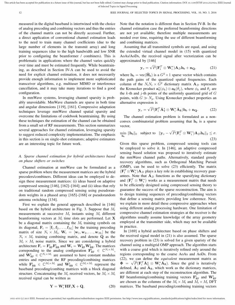
a codebook which includes beam patterns at different resolu-tions. Some simple protocols use an iterative process to ex-change information between the transmitter and receiver usinga narrower and narrower beamwidth at each step, with thepurpose of discovering the angular directions of the strongestsignal between the receiver and transmitter (i.e. the best angle-of-arrival and angle-of-departure), without explicit channelestimation. Codebook beam training strategies [23], [119],[143]–[147] use an iterative process to measure the angularpower over its codebook. Each code in the codebook directsthe beam in a particular angular direction. These trainingstrategies have been implemented in standards like IEEE802.15.3c, IEEE 802.11ad, and Wireless HD, which assumeanalog-only beamforming and single-stream transmission.
To illustrate the beam training concept, we describe theprotocol in IEEE 802.11ad [4]. It uses a specified periodcalled Beam Training Interval (BTI) for the iterative processto occur. This procedure includes three phases illustrated inFig. 8: a) Sector Level Sweep (SLS), a coarse beam adaptationwhich trains a combination of sector (at one end) and antenna(at the other end). The access point transmits the InitiatorTransmit Sector Sweep (TXSS) on each of its sectors up toa maximum of 64 sectors per antenna and a total maximumnumber of sectors of 128. After the access point completesits sweep, the users use carrier sense multiple access (CSMA)with an exponential backoff to begin the Responder SectorSweep (RSS). b) Beam Refinement Protocol (BRP), a finebeam training step which can be used to increase the quality ofthe link if required; it involves training of different transmitand/or receive antenna configurations. BRP packets appendspecial training to IEEE 802.11ad data packets. This trainingfield allows either the receiver or transmitter (but not both atthe same time) to try a new antenna beam. The BRP packetincludes training for channel estimation with the new antennabeam. If the transmitter is refining its beam, the receiver sendsfeedback to the transmitter regarding the success or failure ofthe new beam. c) Beam tracking, a periodic refinement over asmall number of antenna configurations.
Fig. 8. Coarse and fine beam adaptation steps in the 802.11ad beamtrainingprotocol.
A generalization of beam training to hybrid precoding isprovided in [146], assuming a hybrid architecture based onphased shifters. This approach uses a beam training pro-cess that involves adaptive measurements over a multireso-lution dictionary and a low complexity bisection strategy forthe sparse recovery. The algorithm estimates the parameters(AoA/AoD and path gain) of one path per iteration aftersubtracting the contribution of the previously estimated paths.To estimate each path’s parameters, an adaptive search overthe AoA/AoD is performed starting with wide beams in the
early stages and narrowing the search based on the estima-tion outputs in the later stages to focus only on the mostpromising directions. To implement these adaptive beams,a novel multi-resolution beamforming codebook was alsodeveloped. The codebook construction idea depends on ap-proximating the ideal sectored beam patterns directly usinghybrid analog/digital precoders. The main advantage of thishybrid precoding based codebook compared with prior analog-only multi-resolution codebooks is the higher design degreesof freedom given by the extra digital processing layer, whichlead to better beam patterns and more flexibility with RF phaseshifter limitations. One drawback of the adaptive scheme in[146] is the need for a feedback link between the transmitterand receiver. This has been addressed in [148] where a ping-pong algorithm was used along the same lines of [146] toestimate multi-path mmWave channels.
B. Hybrid precoding
Hybrid precoding offers a compromise between system per-formance and hardware complexity. The precoding/combiningprocessing is divided between the analog and digital domains.A number of RF chains much less than the number of antennasis required [32], [34], [122], [128], [134], [146], [149]–[152].In this section we review several hybrid precoding/combiningstrategies for the single-user and multi-user cases and for thedifferent hybrid architectures.
From Fig. 3, assuming flat-fading and perfect synchroniza-tion, the discrete-time model for the received signal for a singlesymbol period is
y =√ρW∗HFs + W∗n, (16)
where ρ represents the average transmitted power per symbol,and n ∈ CNr×1 is the noise vector with N (0, σ2
n) entries.F = FRFFBB is composed of an RF precoder FRF ∈ CNt×Lt
and a baseband precoder FBB ∈ CLt×Ns . Equivalently, thehybrid combiner W = WRFWBB is composed of an RFcombiner WRF ∈ CNr×Lr , and a baseband combiner WBB ∈CLr×Ns . The precoding and combining matrices FRF and WRFare subject to specific constraints depending on the hardwarearchitecture for the RF beamforming stage.
C. Single user hybrid precoding with phase shifters orswitches
In [32], [34], [122], [128], [146], [149], [151], [152], pre-coding/combining processing is divided between the baseband,which uses digital hardware, and the RF that employs anetwork of phase shifters. A hybrid system based on phaseshifters (see Fig 4), imposes the constraint of unit norm entriesin WRF and FRF and further possibly quantized. In [122],[149], hybrid analog/digital precoding which does not exploitchannel structure was considered for both spatial diversity andmultiplexing systems. Other algorithms have been specificallydesigned for mmWave systems, leveraging the special charac-teristics of mmWave channels to simplify the design.
A general approach for hybrid precoding wouldbe to maximize the mutual information given by

1932-4553 (c) 2015 IEEE. Personal use is permitted, but republication/redistribution requires IEEE permission. See http://www.ieee.org/publications_standards/publications/rights/index.html for more information.
This article has been accepted for publication in a future issue of this journal, but has not been fully edited. Content may change prior to final publication. Citation information: DOI 10.1109/JSTSP.2016.2523924, IEEE Journalof Selected Topics in Signal Processing
10 IEEE JOURNAL OF SELECTED TOPICS IN SIGNAL PROCESSING, VOL. 10, NO. 3, 2016
I(ρ,FRF,FBB,WRF,WBB)
= log∣∣I + ρR−1
n W∗HFF∗H∗W∣∣ (17)
where Rn = W∗W and using the definitions of F and Wfrom Section IV-B. Optimizing (17) directly is challenging dueto the constraint sets. An alternative proposed in [32] is to as-sume that the receiver performs ideal decoding, neglecting thereceiver hybrid constraint. Effectively this removes the termsthat depend on W from (17). With some approximations,this leads to a new problem where the hybrid precoders arefound by approximating the unconstrained optimal precoderFopt, given by the channel singular value decomposition (SVD)solution
(FoptRF ,FoptBB ) = arg min
FBB,FRF
‖Fopt − FBBFRF‖F ,
s.t. FRF ∈ FRF,
‖FRFFBB‖2F = Ns, (18)
where FRF is the set of feasible RF precoders which cor-respond to a hybrid architecture based on phase shifters,i.e., the set of Nt × NRF matrices with constant-magnitudeentries. To solve this problem, an orthogonal matching pursuit(OMP) based algorithm was proposed in [32]. It uses a sparsechannel model like in (15) and proposes a related problemthat involves configuring the RF beamforming vectors from adictionary of steering vectors based on channel AoDs. Thissolution was found to be close to the unconstrained digitalsolution and offer substantial gains over the case of single-stream analog beamforming. The hybrid precoding designproblem based on the dictonary approach is extended to anarchitecture based on subarrays in [153]; the sparsity of thechannel is also used to define an efficient way to find thenear-optimal precoder. In [154] the codebook base approach isalso considered, and another method for the efficient selectionof the precoders/combiners is presented. In [155], the semi-unitary structure of the optimum precoder (in the absence ofhardware constraints) is exploited. The search space in thearray manifold is significantly reduced and a much lowercomplexity optimization algorithm is obtained. In [156] thehybrid structure based on phase shifters is further analyzed. Itis theoretically shown that if Lr, Lt ≥ 2Ns, the hybrid systemperforms as the all-digital precoding/combining scheme. Thiswork also proposes an aternative design strategy for theprecoders/combiners when Lr = Lt = Ns, which performsclose to the fully-digital solution. Another solution presentedin [131] performs a simplex 1-D iterative local search for everyelement of the analog precoder; the large number of entrieswhich are updated separately increases the computationalcomplexity.
The design of combiners when the receiver hybrid architec-ture is based on switches (see Fig. 5) instead of phase shiftershas been addressed in [134]. The RF combining/precodingmatrices become selection matrices routing Lr, Lt antennasto the corresponding RF chain. Each column of WRF,FRFis a binary vector with a single one and zeros elsewhere.The combiner design that maximizes mutual information is acombinatorial problem. After some approximations a sparse
reconstruction problem can also be formulated and solvedusing a variant of simultaneous orthogonal matching pursuit(SOMP).
Most work on hybrid precoding like [32], [155], [156]requires the availability of channel knowledge, at least at thereceiver. To relax this assumption, [152] develops a hybridprecoding algorithm for mmWave systems based on partialchannel knowledge. With a two-stage algorithm, [152] showedthat the hybrid precoding performance with perfect channelknowledge can be approached when each of the transmitterand receiver knows only its AoDs (or AoAs). Relaxationsfor hybrid precoding with no channel knowledge and withquantized phase shifters has been considered in [146]. Otherextensions are made for single-stream MIMO-OFDM wherethe analog/digital precoders are designed to maximize eitherthe signal strength or the sum-rate over different sub-carriers[128]. Other variations of hybrid precoding with arrays of sub-arrays of phase shifters were considered in [34], [151]. It wasshown here that this system incurs a small loss compared tothe fully-connected architecture, while the power consumptionis lower. Many other extensions are also important, like hybridprecoding codebook design, and wideband hybrid precoding(see [29] for more suggested future work).
D. Single-user hybrid precoding and combining with lens-based front-end
Precoding and combining for lens-based analog beamform-ing makes use of the beamspace system representation in(9) to exploit the resulting sparsity in the thresholded sub-matrix Hb defined in Section II-E. If CSI is available atthe transmitter, an SVD of Hb = UbΣbV
∗b may be used
[31] for precoding. The matrix Vb is used for precodingat the transmitter and Ub is used for post-processing atthe receiver to create peff = min(|Mr|, |Mt|) orthogonalchannels. A simpler approach exploits the fact that the Fourier(beamspace) basis vectors serve as approximate eigenvectorsfor sparse beamspace mmWave MIMO channels. In this case,no precoding is done at the transmitter, except possibly somepower allocation across the peff transmit data streams. Residualinterference between the different data streams is suppressedvia post-processing at the receiver, e.g., the MMSE receiver[76]. By appropriate thresholding so that most of the channelpower is captured by Hb, both approaches deliver near optimalperformance [76].
E. Precoding and combining with 1-bit ADCs
In [140], where CSIT is assumed, simple channel inversionprecoding (versus the usual eigenbeamforming) is shown tobe nearly optimal if the channel has full row rank. MIMOprecoding eliminates the gap between unquantized and quan-tized achievable rates at low and medium SNRs, and providesa substantial performance improvement compared with the noprecoding case. If full row rank is not true, a different pre-coding method is proposed achieving the high SNR capacity.Despite this potential gain, limited feedback precoding with1-bit ADCs, including suitable codebook design, remains asan open problem. Further, most work on low resolution ADCs

1932-4553 (c) 2015 IEEE. Personal use is permitted, but republication/redistribution requires IEEE permission. See http://www.ieee.org/publications_standards/publications/rights/index.html for more information.
This article has been accepted for publication in a future issue of this journal, but has not been fully edited. Content may change prior to final publication. Citation information: DOI 10.1109/JSTSP.2016.2523924, IEEE Journalof Selected Topics in Signal Processing
HEATH et al.: AN OVERVIEW OF SIGNAL PROCESSING TECHNIQUES FOR MILLIMETER WAVE MIMO SYSTEMS 11
has focused on the single user MIMO setting, and there hasbeen limited work on the multiuser case.
F. Multiuser extensions
Multiuser precoding at mmWave is still an active area ofresearch [73], [157], [158]. The basic idea of most multiuserapproaches is to assign different analog beams to differentusers then possibly use baseband digital processing to furtherreduce inter-user interference.
1) Multiuser precoding and combining in lens-based hybridarchitecture: In [73], [157], an access point (AP) equippedwith an N -dimensional ULA (or a lens-based front-end) that iscommunicating with K single-antenna mobile stations (MSs)is considered. The multiuser channel is characterized by theN×K channel matrix H where each column (hk) correspondsto the channel vector for a different user. The beamspacechannel presentation is given by
Hb = U∗H = [hb,1,hb,2, · · · ,hb,K ] ;
hb,k = U∗hk , k = 1, 2, · · · ,K(19)
where hb,k is the beamspace channel representation of the k-th MS. An important property of Hb is that it has a sparsestructure representing the directins of the different MSs, asillustrated in Fig. 9(a). Each user, represented by hb,k isassociated with a set of dominant beams as illustrated byrows in Fig. 9(a). These dominant beams define the beammasks Mk for different users via a thresholding operationresulting in an overall beam mask M; see Fig. 9(b). Thereduced complexity access point operates on these selectedp = |M| � N beams for precoding in the downlink andcombining in the uplink.
(a)
(b)
Fig. 9. (a) Contour plot of |HHb |
2 for a ULA with N = 81, representing thebeamspace channel vectors (rows) for 20 MSs randomly distributed between±90o (b) Illustration of beam masks Mk and M for the Hb in (a).
The downlink system model is given by y = H∗x+v wherey is the K×1 vector of received signals at the K MSs, and x isthe N×1 is the transmitted signal. In a conventional (massive)MIMO system, a linear precoder takes the form x = Gs,where s is the vector of symbols for different MSs, and Gis the N × K precoding matrix that can be designed usingvarious criteria, e.g. MMSE [159], [160]. In beamspace, thedownlink system model is given by y = H∗bxb+v ≈ H∗b xb+v, where x = UNxb, and the second equality represents the
lower dimensional system characterized by p × K channelmatrix Hb, and a corresponding p×K precoding matrix Gb;xb = Gbx [73], [157]. The design of Gb is computationallyless intensive (compared to G) since p� N .
The uplink system model is given by y = Hx + v wherex represents the vector of independent symbols from the KMSs, and y represents the received signal at the access point.In a conventional MIMO system, the combiner operates ony. In beamspace, the combiner operates on yb = U∗Ny, inparticular on the p dominant beams in yb = Hbx+ v, therebygreatly reducing complexity as in the downlink case.
By capturing a sufficiently large fraction of channel power(via the choice of thresholds γk), the reduced-complexitylinear beamspace precoders/combiners can be designed to de-liver near-optimal performance [73], [157]. Using lens-based(or phase-shifter-based) front-end for analog beamformingcan further reduce hardware complexity. Integration of beamselection and multiuser channel estimation warrants furtherinvestigation.
2) Multiuser precoding in the hybird precoding frame-work: Hybrid precoding was also considered for multi-usermmWave systems [158]. In [158], the downlink mmWavesystem was considered with the basestation employing hybridanalog/digital architecture and mobile users having analog-only combining (see Fig. 10). For this system, a two-stagehybrid precoding algorithm was proposed and proved toachieve a near-optimal performance compared to a certainfully-digital approach. At the first stage, the analog beam-former and combiner are designed to maximize the power ateach user by single-user beam-training. At the second stagethe baseband precoder is designed from the channel estimatesperformed at the users side to reduce inter-user interference.Only effective channels need to be trained, due to dimen-sionality reduction. The performance of multi-user mmWavesystems with limited feedback, i.e. with quantizing both theanalog and digital precoders, was also studied in [158]. It wasshown that quantization of the baseband precoders is speciallycritical to preserve the hybrid precoding gain over analog-onlybeamsteering strategies. Further work is needed to develophybrid precoding for both uplink and downlink with differentprecoding and combining strategies, and also for frequencyselective channels.
Fig. 10. System model for the multiuser hybrid precoding design.
V. CHANNEL ESTIMATION AT MMWAVE
Channel estimates are useful for configuring the analogand digital beamformers that may be used in a mmWavesystem [29]. Conventional channel MIMO channel estimationis difficult to apply in mmWave systems that use analogprecoding and combining. The reason is that the channel
1932-4553 (c) 2015 IEEE. Personal use is permitted, but republication/redistribution requires IEEE permission. See http://www.ieee.org/publications_standards/publications/rights/index.html for more information.
This article has been accepted for publication in a future issue of this journal, but has not been fully edited. Content may change prior to final publication. Citation information: DOI 10.1109/JSTSP.2016.2523924, IEEE Journalof Selected Topics in Signal Processing
12 IEEE JOURNAL OF SELECTED TOPICS IN SIGNAL PROCESSING, VOL. 10, NO. 3, 2016
measured in the digital baseband is intertwined with the choiceof analog precoding and combining vectors and thus the entriesof the channel matrix can not be directly accessed. Further,a direct application of conventional channel estimation leadsto the need to train many channel coefficients (due to thelarge number of elements in the transmit array) and longtraining sequences (due to the high bandwidth and low SNRprior to configuring the beamformer / combiners). This isproblematic in applications where the channel varies quicklyover time and must be estimated frequently. While beamtrain-ing, as described in Section IV-A can be used to avoid theneed for explicit channel estimation, it does not necessarilyprovide enough information to implement more sophisticatedtransceiver algorithms, e.g. multiuser MIMO or interferencecancellation, and it may take many iterations to find a goodconfiguration.
In mmWave systems, leveraging channel sparsity is prob-ably unavoidable. MmWave channels are sparse in both timeand angular dimensions [119], [161]. Compressive adaptationtechniques leverage mmWave channel spatial sparsity andovercome the limitations of codebook beamtraining. By usingthese techniques the estimation of the channel can be obtainedfrom a small set of RF measurements. This section summarizesseveral approaches for channel estimation, leveraging sparsityto suggest reduced complexity implementations. The emphasisin this section is on single-shot estimators; adaptive estimatorsare an interesting topic for future work.
A. Sparse channel estimation for hybrid architectures basedon phase shifters or switches
Channel estimation at mmWave can be formulated as asparse problem where the measurement matrices are the hybridprecoders/combiners. Different ideas can be employed to de-sign these measurement matrices: (i) ideas based on adaptivecompressed sensing [146], [162]–[164]; and (ii) ideas that relyon traditional random compressed sensing using pseudoran-dom weights in a phased array [165]–[168] or pseudorandomantenna switching [134].
First we explain the general approach described in [146]based on the hybrid architecture in Fig. 3. Suppose that Mrmeasurements at successive Mr instants using Mt differentbeamforming vectors at Mt time slots are performed. Let Xbe a diagonal matrix containing the Mt training symbols onits diagonal, Ft = [f1, f2, . . . , fMt ] be the training precodingmatrix of size Nt × Mt, Wt = [w1,w2, . . . ,wMr ] be theNr × Mr training combining matrix, and denote Q as theMr × Mt noise matrix. Since we are considering a hybridarchitecture Ft = Ft
RFFtBB and Wt = Wt
RFWtBB. The matrices
correponding to the analog configuration FtRF ∈ CNt×Mt ,
and WtRF ∈ CNr×Mr are assumed to have constant modulus
entries and represent the RF precoding/combining matriceswhile Ft
BB ∈ CMt×Mt and WtBB ∈ CMr×Mr represent the
baseband precoding/combing matrices with a block diagonalstructure. Concatenating the Mr received vectors, he Mr×Mtreceived signal can be written as
Y = W∗t HFtX + Q, (20)
Note that the notation is different than in Section IV-B. In thechannel estimation case the preferred beamforming directionsare not yet available; therefore multiple measurements areneeded over time, requiring the use of different beamformingand combining matrices.
Assuming that all transmitted symbols are equal, and usingthe extended virtual channel model in (15) with quantizedAoAs/AoDs, the received signal after vectorization can beapproximated by [146]
yv =√P (FTt ⊗W∗
t )ADhb + nQ, (21)
where hb = vec(Hb) is a G2×1 sparse vector which containsthe path gains of the quantized spatial frequencies. Eachcolumn of the NtNr × G2 dictionary matrix AD representsthe Kronecker product a∗T(φk)⊗ aR(θj), where φk and θj arethe k-th and j-th points of the uniformly quantized grid of Gpoints, with G� Np. Using Kronecker product properties analternative expression is
yv =√P (FTt A∗T ⊗W∗
t AR)hb + nQ. (22)
The channel estimation problem is formulated as a non-convex combinatorial problem assuming that hb is a sparsevector,
minhb‖hb‖0 subject to ‖yv −
√P (FTt ⊗W∗
t )ADhb‖2 ≤ σ.(23)
Given this sparse problem, compressed sensing tools canbe employed to solve it. In [146], an adaptive compressedsensing based solution was proposed to iteratively estimatethe mmWave channel paths. Alternatively, standard greedyrecovery algorithms, such as Orthogonal Matching Pursuit(OMP), can be used to solve (23) efficiently. The matrix(FTt ⊗W∗
t )AD plays a key role in establishing recovery guar-antees. Note that AD functions as the sparsifying dictionaryand (FTt ⊗W∗
t ) works as a measurement matrix that needsto be efficiently designed using compressed sensing theory toguarantee the success of the sparse reconstruction. The aim isto design training sequences of precoding/combining vectorsthat define a sensing matrix providing low coherence. Next,we explain in more detail these compressive approaches whenusing different analog processing hardware. One limitation ofcompressive channel estimation strategies at the receiver is thealgorithms usually assume knowledge of the array geometryemployed at the transmitter side, which may not be availablein practice.
In [169] a hybrid architecture based on phase shifters andthe received signal model in (21) is also assumed. The sparserecovery problem in (23) is solved for a given sparisty of thechannel using a multigrid OMP approach. The algorithm startswith a coarse grid which is iteratively refined only around theregions corresponding to the coarse AoAs and AoDs. From(22), we can define the equivalent measurement matrix asΦ =
√P (FTt A∗T ⊗ W∗
t AR). Since the grid is iterativelydefined, AT and AR, which work as the dictionary matrices,are different at each step of the reconstruction algorithm. TheRF beamforming/combining training vectors Ft
RF and WtRF
are chosen as the columns of the Mt×Mt and Mr×Mr DFTmatrices. The baseband precoding/combining training vectors

1932-4553 (c) 2015 IEEE. Personal use is permitted, but republication/redistribution requires IEEE permission. See http://www.ieee.org/publications_standards/publications/rights/index.html for more information.
This article has been accepted for publication in a future issue of this journal, but has not been fully edited. Content may change prior to final publication. Citation information: DOI 10.1109/JSTSP.2016.2523924, IEEE Journalof Selected Topics in Signal Processing
HEATH et al.: AN OVERVIEW OF SIGNAL PROCESSING TECHNIQUES FOR MILLIMETER WAVE MIMO SYSTEMS 13
FtBB and Wt
BB are designed to minimize the coherence of theinitial equivalent measurement matrix.
A hybrid architecture based on phase shifters constrains theRF precoding/combining matrices to have unit norm entries.An architecture based on switches restricts each column ofFt
RF and WtRF to have exactly a one at the index of the
selected antenna and zeros elsewhere. In [134], it was shownthat analog-only binary pseudorandom combining matricesbased on switches provide equal or even lower coherence thanmeasurement matrices associated to an architecture based onphase shifters. Besides of having a similar channel estimationperformance, hybrid architectures based on switches lead to alower power consumption with respect to phase shifters.
The contributions summarized above show the success ofcompressive channel estimation in simple mmWave systems.Many open problems remain. To further increase the perfor-mance of sparse recovery algorithms, it would be interestingto design alternative training precoders/combiners at RF andbaseband that minimize the coherence of the equivalent mea-surement matrix. It is also interesting to analyze the trade-offs between the training length and the number of RF chainsfor the different architectures. The design of limited feedbackstrategies for the mmWave MIMO channel is also interesting,as the estimators and quantizers are intertwined. Estimatingthe array geometry at the same time as the channel is anotherchallenging direction, as is feedback and feedforward of arraygeometry information. Finally, it would be interesting to for-mulate the channel estimation problem for a multi-cell systemand a wideband channel model, to study the influence of theinter-cell interference into the performance of compressivechannel estimators.
B. Beam training and sparse channel estimation in lens-basedCAP-MIMO transceivers
Consider and Nr×Nt mmWave MIMO system with a lens-based transceiver architecture such as CAP-MIMO. Channelestimation consists of two steps: i) determining the channelbeam masks, M, Mt and Mr, defined in Sec. II-E, thatdetermine the low-dimensional beamspace channel matrix Hb,and ii) estimation of the entries of Hb. The second step canbe accomplished by sequentially exciting the transmit beamsin Mt and, for each excited transmit beam, measuring thecorresponding receive beams inMr. This yields a columnwiseestimate Hb [170]. The determination of M essentially boilsdown to sequential transmission and thresholding: sequentiallyexciting different transmit beams, and determining the re-ceive beams with sufficiently high power for each transmittedbeam. This approach generally requires somewhere betweenO(N) and O(N2) transmissions, depending on the numberof simultaneous measurements possible at the receiver. Whilemany different algorithms can be developed, the choice of thethreshold in determining dominant channel entries is key.
C. Channel estimation with 1-bit architectures
Channel estimation with one-bit ADCs for the MIMO chan-nel in general [171], [172] and in the context of mmWave [142]is surprisingly effective when understood from a mathematical
perspective. In [142], channel sparsity is exploited and thenarrowband virtual channel model in (15) is considered, whichallows for a sparse recovery problem to be formulated. Thereceived signal using this particular architecture can be writtenas
Y = sign(HFtX + Q), (24)
where X is the training sequence and Q is the i.i.d. Gaussiannoise. Using the virtual channel representation in (9), settingFt = UNt , using the training sequence X = FtZ
vec(Y) = sign((ZT ⊗UNr)vec(Hb) + vec(Q)). (25)
The problem of estimating hb = vec(Hb) given Z, UNr andthe received signal can be solved using the one-bit compressivesensing framework introduced in [141] to recover sparsevectors. The reconstruction can be further improved if priorinformation about the distribution of hb is used [142]. In thiscase, the generalized approximate message passing (GAMP)algorithm can be used to solve the optimization problem in asmall number of steps.
Channel estimation of the broadband channel is an activearea of research. The closed-form ML estimator of the channelcan be derived for the one-tap SISO channel [171], but itis intractable for frequency-selective channels. Prior workproposed to transmit periodic bursty training sequences andestimate each tap of the channel responses separately [172],[173]. A more efficient way is to include the correlation of thechannel responses (for instance, the sparsity of the mmWavechannel [142]). The GAMP algorithm is also appealing in thiscase [142], [174], [175].
D. Multiuser channel estimation
In [168], a compressed-sensing based multi-user mmWavesystem operation was proposed in which the basestationand mobile users employ random beamforming/measurementmatrices to estimate the downlink channel parameters(AoAs/AoDs and path gains). Then, quantized AoA/AoDknowledge is fed back to the basestation, which uses this toconstruct the data transmission beamforming vectors. Apartfrom adaptive compressed sensing, random compressed sens-ing may be more suitable for multi-user systems as all themobile users can simultaneously estimate their channels thanksto the randomness nature of the transmitted beams. One impor-tant question when random compressed sensing tools are usedto estimate mmWave channels is how many measurements areneed? To give an initial answer to this question, [168] derived asimple expression for the per-user achievable rate as a functionof the number of compressed sensing measurements in somespecial cases. It was shown that at least an order of magnitudefewer compressed sensing measurements are needed comparedwith exhaustive search solutions. Further work is needed todevelop multi-user channel estimation strategies for hybridprecoding, low resolution ADCs, and broadband channels.
VI. CONCLUSIONS
Communicating at mmWave is not simply a matter of justchanging the carrier frequency. Going to mmWave changes

1932-4553 (c) 2015 IEEE. Personal use is permitted, but republication/redistribution requires IEEE permission. See http://www.ieee.org/publications_standards/publications/rights/index.html for more information.
This article has been accepted for publication in a future issue of this journal, but has not been fully edited. Content may change prior to final publication. Citation information: DOI 10.1109/JSTSP.2016.2523924, IEEE Journalof Selected Topics in Signal Processing
14 IEEE JOURNAL OF SELECTED TOPICS IN SIGNAL PROCESSING, VOL. 10, NO. 3, 2016
the assumptions that underly prior developments in signalprocessing for communication. The radio frequency hard-ware introduces constraints that have ramifications on thebeamforming, precoding, and channel estimation algorithms.The propagation channel has higher dimension, with morespatial sparsity, different pathloss characteristics, and extremesensitivity to blockage. Large antenna arrays may be usedfor both transmission and reception, renewing the importanceof MIMO communication. There are many open researchproblems relating to channel modeling, precoding, receiverdesign, channel estimation, and broadband channels, not tomention system design challenges that arise when mmWave isused in personal area networks, local area networks, cellularnetworks, vehicular networks, or wearable networks. There is abright future ahead in signal processing for mmWave wirelesssystems.
REFERENCES
[1] T. S. Rappaport, R. W. Heath Jr., R. C. Daniels, and J. Murdock,Millimeter Wave Wireless Communications. Prentice-Hall, September2014.
[2] D. Emerson, “The work of Jagadis Chandra Bose: 100 years ofmillimeter-wave research,” IEEE Trans. Microw. Theory Techn., vol. 45,no. 12, pp. 2267–2273, Dec 1997.
[3] “WirelessHD Specification Overview,” Tech. Rep., 2010.[4] “ISO/IEC/IEEE International Standard for Information technology–
Telecommunications and information exchange between systems–Local and metropolitan area networks–Specific requirements-part11: Wireless LAN Medium Access Control (MAC) and PhysicalLayer (PHY) Specifications Amendment 3: Enhancements for VeryHigh Throughput in the 60 GHz Band (adoption of IEEE Std802.11ad-2012),” ISO/IEC/IEEE 8802-11:2012/Amd.3:2014(E), pp. 1–634, March 2014.
[5] F. Giannetti, M. Luise, and R. Reggiannini, “Mobile and personalcommunications in 60 GHz band: A survey,” Wirelesss PersonalComunications, vol. 10, pp. 207 – 243, 1999.
[6] H. Xu, V. Kukshya, and T. S. Rappaport, “Spatial and temporalcharacteristics of 60 GHz indoor channel,” IEEE J. Sel. Areas. Com-munications, vol. 20, no. 3, pp. 620 – 630, April 2002.
[7] A. Bourdoux, J. Nsenga, W. Van Thillo, F. Horlin, and L. Van der Perre,“Air interface and physical layer techniques for 60 GHz WPANs,” pp.1–6, Nov 2006.
[8] P. Smulders, H. Yang, and I. Akkermans, “On the design of low-cost 60-GHz radios for multigigabit-per-second transmission over shortdistances [topics in radio communications],” IEEE Commun. Mag.,vol. 45, no. 12, pp. 44–51, December 2007.
[9] R. Daniels and R. Heath, “60 GHz wireless communications: emergingrequirements and design recommendations,” IEEE Veh. Technol. Mag.,vol. 2, no. 3, pp. 41–50, Sept 2007.
[10] S. Singh, F. Ziliotto, U. Madhow, E. Belding, and M. Rodwell,“Blockage and directivity in 60 GHz wireless personal area networks:from cross-layer model to multihop MAC design,” IEEE J. Sel. AreasCommun., vol. 27, no. 8, pp. 1400–1413, October 2009.
[11] R. Daniels, J. Murdock, T. Rappaport, and R. Heath, “60 GHz wireless:up close and personal,” IEEE Microw. Mag., vol. 11, no. 7, pp. 44–50,Dec 2010.
[12] E. Torkildson, U. Madhow, and M. Rodwell, “Indoor millimeter waveMIMO: Feasibility and performance,” IEEE Trans. Wireless Commun.,vol. 10, no. 12, pp. 4150–4160, December 2011.
[13] S. Singh, R. Mudumbai, and U. Madhow, “Interference analysis forhighly directional 60-GHz mesh networks: The case for rethinkingmedium access control,” IEEE/ACM Trans. on Networking, vol. 19,no. 5, pp. 1513–1527, Oct 2011.
[14] Z. Pi and F. Khan, “An introduction to millimeter-wave mobile broad-band systems,” IEEE Commun. Mag., vol. 49, no. 6, pp. 101–107,2011.
[15] T. S. Rappaport, S. Shu, R. Mayzus, Z. Hang, Y. Azar, K. Wang, G. N.Wong, J. K. Schulz, M. Samimi, and F. Gutierrez, “Millimeter wavemobile communications for 5G cellular: It will work!” IEEE Access,vol. 1, pp. 335–349, 2013.
[16] M. R. Akdeniz, Y. Liu, M. K. Samimi, S. Sun, S. Rangan, T. S.Rappaport, and E. Erkip, “Millimeter wave channel modeling andcellular capacity evaluation,” IEEE J. Sel. Areas Commun., vol. 32,no. 6, pp. 1164–1179, June 2014.
[17] W. Roh, J.-Y. Seol, J. Park, B. Lee, J. Lee, Y. Kim, J. Cho, K. Cheun,and F. Aryanfar, “Millimeter-wave beamforming as an enabling tech-nology for 5G cellular communications: theoretical feasibility andprototype results,” IEEE Commun. Mag., vol. 52, no. 2, pp. 106–113,2014.
[18] T. Bai and R. W. Heath Jr., “Coverage and rate analysis for millimeter-wave cellular networks,” IEEE Trans. Wireless Commun., vol. 14, no. 2,pp. 1100–1114, Feb 2015.
[19] Federal Communications Commission, “FCC 15-138 notice of pro-posed rule making,” Oct 2015.
[20] J. Mitola and G. Q. Maguire Jr., “Cognitive radio: making softwareradios more personal,” IEEE Pers. Commun., vol. 6, no. 4, pp. 13–18,Aug 1999.
[21] S. Haykin, “Cognitive radio: brain-empowered wireless communica-tions,” IEEE J. Sel. Areas Commun., vol. 23, no. 2, pp. 201–220, Feb2005.
[22] B. Walke and R. Briechle, “A local cellular radio network for digitalvoice and data transmission at 60GHz,” London, Nov 1985, pp.215–225. [Online]. Available: http://www.comnets.rwth-aachen.de
[23] S. Hur, T. Kim, D. J. Love, J. V. Krogmeier, T. A. Thomas, andA. Ghosh, “Millimeter wave beamforming for wireless backhaul andaccess in small cell networks,” IEEE Trans. Commun., vol. 61, no. 10,pp. 4391–4403, Oct. 2013.
[24] C. Dehos, J. L. Gonzalez, A. De Domenico, D. Ktenas, and L. Dussopt,“Millimeter-wave access and backhauling: the solution to the exponen-tial data traffic increase in 5G mobile communications systems?” IEEECommun. Mag., vol. 52, no. 9, pp. 88–95, September 2014.
[25] S. Singh, M. N. Kulkarni, A. Ghosh, and J. G. Andrews, “Tractablemodel for rate in self-backhauled millimeter wave cellular networks,”IEEE J. Sel. Areas Commun., 2015.
[26] H. H. Meinel and J. Dickmann, “Automotive radar: From its origins tofuture directions,” Microwave Journal, vol. 56, no. 9, pp. 24–28, 2013.
[27] C. Sturm and W. Wiesbeck, “Waveform design and signal processingaspects for fusion of wireless communications and radar sensing,” Proc.IEEE, vol. 99, no. 7, pp. 1236–1259, July 2011.
[28] A. Pyattaev, K. Johnsson, S. Andreev, and Y. Koucheryavy, “Commu-nication challenges in high-density deployments of wearable wirelessdevices,” IEEE Wireless Commun., vol. 22, no. 1, pp. 12–18, February2015.
[29] A. Alkhateeb, M. Jianhua, N. Gonzalez-Prelcic, and R. W. Heath Jr.,“MIMO precoding and combining solutions for millimeter-wave sys-tems,” IEEE Commun. Mag., vol. 52, no. 12, pp. 122–131, December2014.
[30] J. Brady, N. Behdad, and A. M. Sayeed, “Beamspace MIMO formillimeter-wave communications: System architecture, modeling, anal-ysis and measurements,” IEEE Trans. Antennas Propag., vol. 61, no. 7,pp. 3814–3827, July 2013.
[31] A. M. Sayeed and N. Behdad, “Continuous aperture phased MIMO:Basic theory and applications,” Proc. 2010 Annual Allerton Conferenceon Communications, Control and Computers, pp. 1196–1203, Sep.2010.
[32] O. El Ayach, S. Rajagopal, S. Abu-Surra, Z. Pi, and R. W. Heath Jr.,“Spatially sparse precoding in millimeter wave MIMO systems,” IEEEJ. Sel. Areas Commun., vol. 13, no. 3, pp. 1499–1513, March 2014.
[33] A. Alkhateeb, O. El Ayach, G. Leus, and R. W. Heath Jr., “Channelestimation and hybrid precoding for millimeter wave cellular systems,”IEEE J. Sel. Topics Signal Process., vol. 8, no. 5, pp. 831–846, Oct2014.
[34] S. Han, C.-L. I, Z. Xu, and C. Rowell, “Large-scale antenna systemswith hybrid analog and digital beamforming for millimeter wave 5G,”IEEE Commun. Mag., vol. 53, no. 1, pp. 186–194, January 2015.
[35] W. U. Bajwa, J. Haupt, A. M. Sayeed, and R. Nowak, “CompressedChannel Sensing: A New Approach to Estimating Sparse MultipathChannels,” Proc. IEEE, vol. 98, no. 6, pp. 1058–1076, Jun. 2010.
[36] A. M. Sayeed, “Deconstructing multi-antenna fading channels,” IEEETrans. Signal Process., vol. 50, no. 10, pp. 2563–2579, Oct. 2002.
[37] J. Mo and R. W. Heath Jr., “High SNR capacity of millimeter waveMIMO systems with one-bit quantization,” in Proc. of Inf. Theory andApplications (ITA) Workshop, 2014.
[38] J. Mo, P. Schniter, N. Gonzalez-Prelcic, and R. W. Heath Jr, “Channelestimation in millimeter wave MIMO systems with one-bit quantiza-tion,” Proc. of the Asil. Conf. on Sig. Sys. and Comp., 2014.

1932-4553 (c) 2015 IEEE. Personal use is permitted, but republication/redistribution requires IEEE permission. See http://www.ieee.org/publications_standards/publications/rights/index.html for more information.
This article has been accepted for publication in a future issue of this journal, but has not been fully edited. Content may change prior to final publication. Citation information: DOI 10.1109/JSTSP.2016.2523924, IEEE Journalof Selected Topics in Signal Processing
HEATH et al.: AN OVERVIEW OF SIGNAL PROCESSING TECHNIQUES FOR MILLIMETER WAVE MIMO SYSTEMS 15
[39] M. Cudak, T. Kovarik, T. Thomas, A. Ghosh, Y. Kishiyama, andT. Nakamura, “Experimental mmWave 5G cellular system,” in Globe-com Workshops (GC Wkshps), 2014, Dec 2014, pp. 377–381.
[40] G. Rebeiz, S.-Y. Kim, O. Inac, W. Shin, O. Gurbuz, Y.-C. Ou, F. Gol-cuk, T. Kanar, and B.-H. Ku, “Millimeter-wave large-scale phased-arrays for 5G systems,” in Microwave Symposium (IMS), 2015 IEEEMTT-S International, May 2015, pp. 1–3.
[41] T. S. Rappaport, Wireless Communications: Principles and Practice,2nd ed. Upper Saddle River, NJ: Prentice Hall, 2002.
[42] M. R. Williamson, G. E. Athanasiadou, and A. R. Nix, “Investigatingthe effects of antenna directivity on wireless indoor communication at60 GHz,” in Proc. IEEE Int. Symp. on Pers., Ind. and Mobile RadioComm. (PIMRC), vol. 2, 1997, pp. 635–639.
[43] B. Neekzad, K. Sayrafian-Pour, J. Perez, and J. S. Baras, “Comparisonof ray tracing simulations and millimeter wave channel soundingmeasurements,” in Proc. IEEE Int. Symp. on Pers., Ind. and MobileRadio Comm. (PIMRC), 2007, pp. 1–5.
[44] C. Tolbert and A. Straiton, “Attenuation and fluctuation of millimeterradio waves,” in IRE Int. Conv. Rec., vol. 5, 1966, pp. 12–18.
[45] A. R. Tharek and J. P. McGeehan, “Propagation and bit error ratemeasurements within buildings in the millimeter wave band about 60GHz,” in Proc. Europ. Conf. on Electrotech., 1988, pp. 318–321.
[46] T. Zwick, T. J. Beukema, and H. Nam, “Wideband channel sounderwith measurements and model for the 60 GHz indoor radio channel,”IEEE Trans. Veh. Technol., vol. 54, no. 4, pp. 1266 – 1277, July 2005.
[47] C. R. Anderson and T. S. Rappaport, “In-building wideband partitionloss measurements at 2.5 and 60 GHz,” IEEE Trans. Wireless Commun.,vol. 3, no. 3, pp. 922 – 928, May 2004.
[48] P. F. M. Smulders and A. G. Wagemans, “Wideband indoor radiopropagation measurements at 58 GHz,” Electronics Letters, vol. 28,no. 13, pp. 1270 –1272, June 1992.
[49] T. Manabe, Y. Miura, and T. Ihara, “Effects of antenna directivityand polarization on indoor multipath propagation characteristics at 60GHz,” IEEE J. Sel. Areas Comm., vol. 14, no. 3, pp. 441 –448, April1996.
[50] E. Ben-Dor, T. S. Rappaport, Y. Qiao, and S. J. Lauffenburger,“Millimeter-wave 60 GHz outdoor and vehicle AOA propagationmeasurements using a broadband channel sounder,” in Proc. IEEEGlob. Telecom. Conf. (GLOBECOM), 2011, pp. 1–6.
[51] T. S. Rappaport, F. Gutierrez, E. Ben-Dor, J. N. Murdock, Y. Qiao, andJ. I. Tamir, “Broadband millimeter-wave propagation measurementsand models using adaptive-beam antennas for outdoor urban cellularcommunications,” IEEE Trans. Antennas Propag., vol. 61, no. 4, pp.1850–1859, 2013.
[52] Y. Azar, G. N. Wong, K. Wang, R. Mayzus, J. K. Schulz, H. Zhao,F. Gutierrez, D. Hwang, and T. S. Rappaport, “28 GHz propagationmeasurements for outdoor cellular communications using steerablebeam antennas in New York City,” in Proc. IEEE Int. Conf. Commun.(ICC). IEEE, 2013, pp. 5143–5147.
[53] F. Boccardi, R. W. Heath Jr., A. Lozano, T. L. Marzetta, andP. Popovski, “Five disruptive technology directions for 5G,” IEEECommun. Mag., vol. 52, no. 2, pp. 74–80, February 2014.
[54] K. C. Allen, N. DeMinco, J. R. Hoffman, Y. Lo, and P. B. Papazian,Building penetration loss measurements at 900 MHz, 11.4 GHz, and28.8 MHz, ser. NTIA report – 94-306. Boulder, CO: U.S. Dept. ofCommerce, National Telecommunications and Information Adminis-tration, 1994.
[55] A. V. Alejos, M. G. Sanchez, and I. Cuinas, “Measurement and analysisof propagation mechanisms at 40 GHz: Viability of site shielding forcedby obstacles,” IEEE Trans. Veh. Technol., vol. 57, no. 6, pp. 3369–3380,2008.
[56] H. Zhao, R. Mayzus, S. Sun, M. Samimi, J. K. Schulz, Y. Azar,K. Wang, G. N. Wong, F. Gutierrez, and T. S. Rappaport, “28 GHzmillimeter wave cellular communication measurements for reflectionand penetration loss in and around buildings in New York City,” inProc. IEEE Int. Conf. Commun. (ICC), 2013.
[57] J. S. Lu, D. Steinbach, P. Cabrol, and P. Pietraski, “Modeling humanblockers in millimeter wave radio links,” ZTE Communications, vol. 10,no. 4, pp. 23–28, Dec. 2012.
[58] F. K. Schwering, E. J. Violette, and R. H. Espeland, “Millimeter-wave propagation in vegetation: Experiments and theory,” IEEE Trans.Geosci. Remote Sens., vol. 26, no. 3, pp. 355–367, 1988.
[59] G. M. Comparetto, “Impact of dust and foliage on signal attenuationin the millimeter wave regime,” in Optical Engineering and Photonicsin Aerospace Sensing, 1993, pp. 81–94.
[60] H. J. Liebe, “MPM–An atmospheric millimeter-wave propagationmodel,” International Journal of Infrared and Millimeter Waves,vol. 10, no. 6, pp. 631–650, 1989.
[61] T. S. Rappaport, J. N. Murdock, and F. Gutierrez, “State of the art in60 GHz integrated circuits and systems for wireless communications,”Proc. IEEE, vol. 99, no. 8, pp. 1390 – 1436, August 2011.
[62] 3GPP, “Further advancements for E-UTRA physical layer aspects,” TR36.814 (release 9), 2010.
[63] T. Bai, R. Vaze, and R. W. Heath Jr., “Analysis of blockage effectson urban cellular networks,” IEEE Trans. Wireless Commun., vol. 13,no. 9, pp. 5070–5083, Sept 2014.
[64] M. Kulkarni, S. Singh, and J. Andrews, “Coverage and rate trends indense urban mmwave cellular networks,” in Proc. IEEE Glob. Telecom.Conf. (GLOBECOM), Dec 2014, pp. 3809–3814.
[65] S. Rangan, T. S. Rappaport, and E. Erkip, “Millimeter-wave cellularwireless networks: Potentials and challenges,” Proc. IEEE, vol. 102,no. 3, pp. 366–385, March 2014.
[66] A. Ghosh, T. Thomas, M. Cudak, R. Ratasuk, P. Moorut, F. Vook,T. Rappaport, G. MacCartney, S. Sun, and S. Nie, “Millimeter-waveenhanced local area systems: A high-data-rate approach for futurewireless networks,” IEEE J. Sel. Areas Commun., vol. 32, no. 6, pp.1152–1163, June 2014.
[67] D. Tse and P. Viswanath, Fundamentals of Wireless Communication.Cambridge University Press, 2007.
[68] A. M. Sayeed and T. Sivanadyan, Wireless Communication and Sensingin Multipath Environments using Multi-antenna Transceivers. Hand-book on Array Processing and Sensor Networks (K. J. R. Liu and S.Haykin, Eds.), IEEE-Wiley, 2010.
[69] S. Geng, J. Kivinen, X. Zhao, and P. Vainikainen, “Millimeter-wavepropagation channel characterization for short-range wireless commu-nications,” IEEE Trans. Veh. Technol., vol. 58, no. 1, pp. 3–13, 2009.
[70] A. Maltsev, V. Erceg, E. Perahia, C. Hansen, R. Maslennikov, A. Lo-mayev, A. Sevastyanov, A. Khoryaev, G. Morozov, M. Jacob et al.,“Channel models for 60 GHz WLAN systems,” doc.: IEEE 802.11-09/0334r7, 2010.
[71] ITU, “M.2134: Requirements related to technical performance for IMT-Advanced radio interfaces,” Technical Report, 2009.
[72] M. Jacob, C. Mbianke, and T. Kurner, “A dynamic 60 GHz radiochannel model for system level simulations with MAC protocols forIEEE 802.11ad,” in Proc. Int. Symp. Consumer Electronics (ISCE),2010, pp. 1–5.
[73] J. Brady and A. M. Sayeed, “Beamspace MU-MIMO high densitygigabit small-cell access at millimeter-wave frequencies,” IEEE Int.Work. on Signal Process. Advances for Wireless Commun. (SPAWC),June 2014.
[74] J. Brady and A. Sayeed, “Wideband communication with high-dimensional arrays: New results and transceiver architectures,” IEEEInt. Conf. on Commun. (ICC), June 2015.
[75] Z. Liu, W. ur Rehman, X. Xu, and X. Tao, “Minimize beam squintsolutions for 60Ghz millimeter-wave communication system,” 2013IEEE Vehicular Technology Conference (VTC) Fall, Sep. 2013.
[76] G. H. Song, J. Brady, and A. M. Sayeed, “Beamspace MIMOtransceivers for low-complexity and near-optimal communication atmm-wave frequencies,” IEEE Int. Conf. on Acoust., Speech and SignalProcess. (ICASSP), pp. 4394–4398, May 2013.
[77] V. Raghavan and A. M. Sayeed, “Sublinear capacity scaling laws forsparse MIMO channels,” IEEE Trans. Inform. Th., pp. 345 – 364, Jan.2011.
[78] J. Kim and I. Lee, “802.11 WLAN: history and new enabling MIMOtechniques for next generation standards,” IEEE Commun. Mag.,vol. 53, no. 3, pp. 134–140, March 2015.
[79] Q. Li, G. Li, W. Lee, M. il Lee, D. Mazzarese, B. Clerckx, and Z. Li,“MIMO techniques in WiMAX and LTE: a feature overview,” IEEECommun. Mag., vol. 48, no. 5, pp. 86–92, May 2010.
[80] J. Zhang, X. Huang, V. Dyadyuk, and Y. Guo, “Massive hybrid antennaarray for millimeter-wave cellular communications,” IEEE WirelessCommun., vol. 22, no. 1, pp. 79–87, February 2015.
[81] C. Doan, S. Emami, D. Sobel, A. Niknejad, and R. Brodersen, “Designconsiderations for 60 GHz CMOS radios,” IEEE Commun. Mag.,vol. 42, no. 12, pp. 132–140, Dec 2004.
[82] B. Le, T. W. Rondeau, J. H. Reed, and C. W. Bostian, “Analog-to-digitalconverters,” IEEE Signal Process. Mag., vol. 22, no. 6, pp. 69–77, Nov2005.
[83] T. Do-Hong and P. Russer, “Signal processing for wideband smartantenna array applications,” IEEE Microw. Mag., vol. 5, no. 1, pp.57–67, Mar 2004.

1932-4553 (c) 2015 IEEE. Personal use is permitted, but republication/redistribution requires IEEE permission. See http://www.ieee.org/publications_standards/publications/rights/index.html for more information.
This article has been accepted for publication in a future issue of this journal, but has not been fully edited. Content may change prior to final publication. Citation information: DOI 10.1109/JSTSP.2016.2523924, IEEE Journalof Selected Topics in Signal Processing
16 IEEE JOURNAL OF SELECTED TOPICS IN SIGNAL PROCESSING, VOL. 10, NO. 3, 2016
[84] B. Floyd, S. Reynolds, U. Pfeiffer, T. Zwick, T. Beukema, andB. Gaucher, “SiGe bipolar transceiver circuits operating at 60 GHz,”IEEE J. Solid-State Circuits, vol. 40, no. 1, pp. 156–167, Jan 2005.
[85] T. LaRocca, J.-C. Liu, and M.-C. Chang, “60 GHz CMOS amplifiersusing transformer-coupling and artificial dielectric differential transmis-sion lines for compact design,” IEEE J. Solid-State Circuits, vol. 44,no. 5, pp. 1425–1435, May 2009.
[86] T. Yao, M. Gordon, K. Yau, M. Yang, and S. Voinigescu, “60-GHzPA and LNA in 90-nm RF-CMOS,” in Radio Frequency IntegratedCircuits (RFIC) Symposium, 2006 IEEE, June 2006, pp. 4 pp.–.
[87] D. Dawn, S. Sarkar, P. Sen, B. Perumana, D. Yeh, S. Pinel, andJ. Laskar, “17-dB-gain CMOS power amplifier at 60GHz,” in IEEEMTT-S International Microwave Symposium Digest, June 2008, pp.859–862.
[88] M. Kraemer, D. Dragomirescu, and R. Plana, “A low-power high-gainLNA for the 60 GHz band in a 65 nm CMOS technology,” in Asia-Pacific Microwave Conference, Dec 2009, pp. 1156–1159.
[89] A. Fonte, S. Saponara, G. Pinto, L. Fanucci, and B. Neri, “60-GHz single-chip integrated antenna and low noise amplifier in 65-nmCMOS SOI technology for short-range wireless Gbits/s applications,”in International Conference on Applied Electronics, Sept 2011, pp. 1–6.
[90] L. Liu, A. Alt, H. Benedickter, and C. Bolognesi, “Low powerconsumption millimeter-wave amplifiers using InP HEMT technology,”in Microwave Workshop Series on Millimeter Wave Integration Tech-nologies, Sept 2011, pp. 9–12.
[91] P.-Y. Chang, S.-H. Su, S. Hsu, W.-H. Cho, and J.-D. Jin, “An ultra-low-power transformer-feedback 60 GHz low-noise amplifier in 90 nmCMOS,” IEEE Microw. Compon. Lett., vol. 22, no. 4, pp. 197–199,2012.
[92] K. J. Kim, K. H. Ahn, T. H. Lim, H. C. Park, and J. W. Yu, “A 60 GHzwideband phased-array LNA with short-stub passive vector generator,”IEEE Microwave and Wireless Components Letters, vol. 20, no. 11,pp. 628–630, 2010.
[93] Y. Yu, P. G. M. Baltus, A. De Graauw, E. Van Der Heijden, C. S.Vaucher, and A. H. M. Van Roermund, “A 60 GHz phase shifterintegrated with LNA and PA in 65 nm CMOS for phased arraysystems,” IEEE Journal of Solid-State Circuits, vol. 45, no. 9, pp.1697–1709, 2010.
[94] A. Natarajan, S. Reynolds, M.-D. Tsai, S. Nicolson, J.-H. Zhan, D. G.Kam, D. Liu, Y.-L. Huang, A. Valdes-Garcia, and B. Floyd, “A Fully-Integrated 16-Element Phased-Array Receiver in SiGe BiCMOS for 60-GHz Communications,” IEEE Journal of Solid-State Circuits, vol. 46,no. 5, pp. 1059–1075, May 2011.
[95] S. Y. Kim, D. W. Kang, K. J. Koh, and G. M. Rebeiz, “An improvedwideband all-pass I/Q network for millimeter-wave phase shifters,”IEEE Trans. on Microw. Theory and Techn., vol. 60, no. 11, pp. 3431–3439, 2012.
[96] J.-L. Kuo et al., “60-GHz four-element phased-array transmit/receivesystem-in-package using phase compensation techniques in 65-nmFlip-Chip CMOS process,” IEEE Trans. Microw. Theory and Techn.,vol. 60, no. 3, pp. 743–756, March 2012.
[97] M. Uzunkol and G. Rebeiz, “A 65 GHz LNA/Phase Shifter with 4.3 dBNF using 45 nm CMOS SOI,” IEEE Microw. Compon. Lett., vol. 22,no. 10, pp. 530–532, Oct 2012.
[98] W. T. Li, Y. C. Chiang, J. H. Tsai, H. Y. Yang, J. H. Cheng, andT. W. Huang, “60-GHz 5-bit phase shifter with integrated VGA phase-error compensation,” IEEE Transactions on Microwave Theory andTechniques, vol. 61, no. 3, pp. 1224–1235, 2013.
[99] J. Borremans, M. Dehan, K. Scheir, M. Kuijk, and P. Wambacq, “VCOdesign for 60 GHz applications using differential shielded inductorsin 0.13 µm CMOS,” in IEEE Radio Frequency Integrated CircuitsSymposium (RFIC), June 2008, pp. 135–138.
[100] Z. Liu, E. Skafidas, and R. Evans, “A 60 GHz VCO with 6 GHz tuningrange in 130 nm bulk CMOS,” in Int. Conf. Microwave and MillimeterWave Technology, vol. 1, April 2008, pp. 209–211.
[101] C.-C. Chen, C.-C. Li, B.-J. Huang, K.-Y. Lin, H.-W. Tsao, andH. Wang, “Ring-based triple-push VCOs with wide continuous tuningranges,” IEEE Trans. Microw. Theory and Techn., vol. 57, no. 9, pp.2173–2183, Sept 2009.
[102] P. Shettigar and S. Pavan, “A 15mW 3.6GS/s CT- δσ ADC with 36MHzbandwidth and 83dB DR in 90nm CMOS,” in IEEE Solid-State CircuitsConference Digest of Technical Papers (ISSCC), Feb 2012, pp. 156–158.
[103] S. Lee, A. Chandrakasan, and H.-S. Lee, “22.4 A 1GS/s 10b 18.9mWtime-interleaved SAR ADC with background timing-skew calibration,”in Solid-State Circuits Conference Digest of Technical Papers (ISSCC),2014 IEEE International, Feb 2014, pp. 384–385.
[104] B.-R.-S. Sung, D.-S. Jo, I.-H. Jang, D.-S. Lee, Y.-S. You, Y.-H. Lee,H.-J. Park, and S.-T. Ryu, “26.4 A 21fJ/conv-step 9 ENOB 1.6GS/S2 × time-interleaved FATI SAR ADC with background offset andtiming-skew calibration in 45nm CMOS,” in IEEE Solid- State CircuitsConference - (ISSCC), Feb 2015, pp. 1–3.
[105] N. Le Dortz, J.-P. Blanc, T. Simon, S. Verhaeren, E. Rouat, P. Urard,S. Le Tual, D. Goguet, C. Lelandais-Perrault, and P. Benabes, “22.5A 1.62GS/s time-interleaved SAR ADC with digital background mis-match calibration achieving interleaving spurs below 70dBFS,” in IEEESolid-State Circuits Conference Digest of Technical Papers (ISSCC),Feb 2014, pp. 386–388.
[106] Y. Dong, R. Schreier, W. Yang, S. Korrapati, and A. Sheikholeslami,“29.2 A 235mW CT 0-3 MASH ADC achieving -167dBFS/Hz NSDwith 53MHz BW,” in IEEE Solid-State Circuits Conference Digest ofTechnical Papers (ISSCC), Feb 2014, pp. 480–481.
[107] E. Janssen, K. Doris, A. Zanikopoulos, A. Murroni, G. van der Weide,Y. Lin, L. Alvado, F. Darthenay, and Y. Fregeais, “An 11b 3.6GS/stime-interleaved SAR ADC in 65nm CMOS,” in IEEE Solid-StateCircuits Conference Digest of Technical Papers (ISSCC), Feb 2013,pp. 464–465.
[108] M. Miyahara, I. Mano, M. Nakayama, K. Okada, and A. Matsuzawa,“A 2.2GS/s 7b 27.4mW time-based folding-flash ADC with resistivelyaveraged voltage-to-time amplifiers,” in IEEE International Solid-StateCircuits Conference, Feb 2014, pp. 388–389.
[109] C.-S. Choi, Y. Shoji, H. Harada, R. Funada, S. Kato, K. Maruhashi,I. Toyoda, and K. Takahashi, “RF impairment models for 60GHz-bandSYS/PHY simulation,” doc.: IEEE 802.15-06-0477-01-003c, 2006.
[110] V. Erceg, M. Messe, A. Tarighat, M. Boers, J. Trachewsky, and C. Choi,“RF impairment modeling,” doc.: IEEE 802.11-09/1213r1, 2009.
[111] U. Rizvi, G. Janssen, and J. Weber, “Impact of RF circuit imperfectionson multi-carrier and single-carrier based transmissions at 60 GHz,” inIEEE Radio and Wireless Symposium, Jan 2008, pp. 691–694.
[112] R. Gomes, Z. Al-Daher, A. Hammoudeh, K. Sobaihi, R. Caldeirinha,and T. Fernandes, “Performance and evaluation of OFDM and SC -FDE over an AWGN propagation channel under RF impairments usingsimulink at 60 GHz,” in Loughborough Antennas and PropagationConference (LAPC), Nov 2014, pp. 685–689.
[113] T. Schenk, RF Imperfections in High-rate Wireless Systems. Springer,2008.
[114] C. Zhang, Z. Xiao, B. Gao, L. Su, and D. Jin, “Robust IQ imbal-ance estimation and compensation via specific preamble for 60 GHzsystems,” in IEEE Wireless Commun. and Netw. Conf. (WCNC), April2013, pp. 4134–4139.
[115] L. Fan, Y. Li, and M. Zhao, “Joint IQ imbalance and PA nonlinearitypre-distortion for highly integrated millimeter-wave transmitters,” inGlobecom Workshops (GC Wkshps), Dec 2014, pp. 399–404.
[116] S. Suyama, Y. Hashimoto, H. Suzuki, and K. Fukawa, “60 GHzOFDM experimental system employing decision-directed phase noisecompensation,” in IEEE Radio and Wireless Symp. (RWS), Jan 2012,pp. 191–194.
[117] M. Fakharzadeh, M.-R. Nezhad-Ahmadi, B. Biglarbegian, J. Ahmadi-Shokouh, and S. Safavi-Naeini, “CMOS phased array transceivertechnology for 60 GHz wireless applications,” IEEE Trans. AntennasPropag., vol. 58, no. 4, pp. 1093–1104, April 2010.
[118] A. Poon and M. Taghivand, “Supporting and enabling circuits forantenna arrays in wireless communications,” Proc. IEEE, vol. 100,no. 7, pp. 2207–2218, July 2012.
[119] J. Wang, Z. Lan, and C. W. Pyo, “Beam codebook based beamformingprotocol for multi-Gbps millimeter-wave WPAN systems,” IEEE J. Sel.Areas Commun., vol. 27, no. 8, pp. 3–4, 2009.
[120] X. Zhang, A. F. Molisch, and S. Kung, “Variable-phase-shift-based RF-baseband codesign for MIMO antenna selection,” IEEE Trans. SignalProcess., vol. 53, no. 11, pp. 4091–4103, Nov. 2005.
[121] P. Sudarshan, N. B. Mehta, A. F. Molisch, and J. Zhang, “Channelstatistics-based RF pre-processing with antenna selection,” IEEE Trans.Wireless Commun., vol. 5, no. 12, pp. 3501–3511, December 2006.
[122] V. Venkateswaran and A.-J. van der Veen, “Analog beamforming inmimo communications with phase shift networks and online channelestimation,” Signal Processing, IEEE Transactions on, vol. 58, no. 8,pp. 4131–4143, Aug 2010.
[123] A. Hajimiri, H. Hashemi, A. Natarajan, X. Guan, and A. Komijani,“Integrated phased array systems in silicon,” Proc. IEEE, vol. 93, no. 9,pp. 1637–1655, Sept 2005.
[124] F. Pivit and V. Venkateswaran, “Joint RF-feeder network and digitalbeamformer design for cellular base-station antennas,” in Antennas andPropagation Society International Symposium (APSURSI), 2013 IEEE,July 2013, pp. 1274–1275.

1932-4553 (c) 2015 IEEE. Personal use is permitted, but republication/redistribution requires IEEE permission. See http://www.ieee.org/publications_standards/publications/rights/index.html for more information.
This article has been accepted for publication in a future issue of this journal, but has not been fully edited. Content may change prior to final publication. Citation information: DOI 10.1109/JSTSP.2016.2523924, IEEE Journalof Selected Topics in Signal Processing
HEATH et al.: AN OVERVIEW OF SIGNAL PROCESSING TECHNIQUES FOR MILLIMETER WAVE MIMO SYSTEMS 17
[125] G. Wang, H. Ding, W. Woods, and E. Mina, “Wideband on-chip RFMEMS switches in a BiCMOS technology for 60 GHz applications,”in Int. Conf. Microwave and Millimeter Wave Technology (ICMMT),vol. 3, April 2008, pp. 1389–1392.
[126] E. Pisek, S. Abu-Surra, J. Mott, T. Henige, and R. Sharma, “Highthroughput millimeter-wave MIMO beamforming system for shortrange communication,” in IEEE Consumer Communications and Net-working Conference (CCNC), Jan 2014, pp. 537–543.
[127] L. Liang, W. Xu, and X. Dong, “Low-complexity hybrid precodingin massive multiuser MIMO systems,” IEEE Wireless Commun. Lett.,vol. 3, no. 6, pp. 653–656, Dec 2014.
[128] C. Kim, T. Kim, and J.-Y. Seol, “Multi-beam transmission diversitywith hybrid beamforming for MIMO-OFDM systems,” in IEEE Globe-com Workshops (GC Wkshps), Dec 2013, pp. 61–65.
[129] C. Kim, T. Kim, J.-S. Son, and J.-Y. Seol, “On the hybrid beamformingwith shared array antenna for mmwave MIMO-OFDM systems,” inIEEE Wireless Commun. Netw. Conf. (WCNC), April 2014, pp. 335–340.
[130] E. Zhang and C. Huang, “On achieving optimal rate of digital precoderby RF-baseband codesign for MIMO systems,” in Proc. IEEE Veh.Tech. Conf. (VTC Fall), Sept 2014, pp. 1–5.
[131] C.-E. Chen, “An iterative hybrid transceiver design algorithm for mil-limeter wave MIMO systems,” IEEE Wireless Commun. Lett., vol. PP,no. 99, pp. 1–1, 2015.
[132] S. Koch, I. Kallfass, R. Weber, A. Leuther, M. Schlechtweg, andS. Saito, “A fully integrated, compound transceiver MIMIC utilizing sixantenna ports for 60 GHz wireless applications,” in IEEE CompoundSemiconductor Integrated Circuit Symposium (CSIC), Oct 2009, pp.1–4.
[133] S. Reyaz, C. Samuelsson, R. Malmqvist, M. Kaynak, and A. Rydberg,“Millimeter-wave RF-MEMS SPDT switch networks in a SiGe BiC-MOS process technology,” in European Microwave Integrated CircuitsConference (EuMIC), Oct 2012, pp. 691–694.
[134] R. Mendez-Rial, C. Rusu, A. Alkhateeb, N. Gonzalez-Prelcic, andR. W. Heath Jr., “Channel estimation and hybrid combining formmwave: Phase shifters or switches?” in Information Theory andApplications Workshop (ITA), Feb 2015.
[135] G. P. Fettweis, “Hetnet wireless fronthaul: The challenge missed,” inIEEE Commun. Theory Workshop, 2014.
[136] O. Dabeer, J. Singh, and U. Madhow, “On the limits of communicationperformance with one-bit analog-to-digital conversion,” in IEEE 7thWorkshop on Signal Processing Advances in Wireless Communications,2006, pp. 1–5.
[137] A. Mezghani and J. Nossek, “On ultra-wideband MIMO systems with1-bit quantized outputs: Performance analysis and input optimization,”in IEEE Int. Symp. on Inf. Th., 2007, pp. 1286–1289.
[138] J. Singh, O. Dabeer, and U. Madhow, “On the limits of communicationwith low-precision analog-to-digital conversion at the receiver,” IEEETrans. Commun., vol. 57, no. 12, pp. 3629–3639, 2009.
[139] A. Mezghani and J. Nossek, “Capacity lower bound of MIMO channelswith output quantization and correlated noise,” in Proc. IEEE Int. Symp.on Inf. Th. (ISIT), 2012.
[140] J. Mo and R. W. Heath, Jr, “Capacity Analysis of One-Bit QuantizedMIMO Systems with Transmitter Channel State Information,” ArXive-prints, Oct. 2014.
[141] L. Jacques, J. Laska, P. Boufounos, and R. Baraniuk, “Robust 1-bitcompressive sensing via binary stable embeddings of sparse vectors,”IEEE Trans. Inf. Theory, vol. 59, no. 4, pp. 2082–2102, April 2013.
[142] J. Mo, P. Schniter, N. Gonzalez-Prelcic, and R. W. Heath Jr., “Channelestimation in millimeter wave MIMO systems with one-bit quantiza-tion,” in Proc. Asilomar Conf. on Signals, Syst. and Comp., 2014.
[143] Y. M. Tsang, A. S. Y. Poon, and S. Addepalli, “Coding the beams:Improving beamforming training in mmWave communication system,”in Proc. IEEE Glob. Telecom. Conf. (GLOBECOM), Dec 2011, pp.1–6.
[144] L. Zhou and Y. Ohashi, “Efficient codebook-based MIMO beamform-ing for millimeter-wave WLANs,” in Proc. IEEE Int. Symp. on Pers.,Ind. and Mobile Radio Comm. (PIMRC), Sept 2012, pp. 1885–1889.
[145] K. Hosoya, N. Prasad, K. Ramachandran, N. Orihashi, S. Kishi-moto, S. Rangarajan, and K. Maruhashi, “Multiple sector ID capture(MIDC): A novel beamforming technique for 60-GHz band multi-GbpsWLAN/PAN systems,” IEEE Trans. Antennas Propag., vol. 63, no. 1,pp. 81–96, Jan. 2015.
[146] A. Alkhateeb, O. E. Ayach, G. Leus, and R. W. Heath Jr., “ChannelEstimation and Hybrid Precoding for Millimeter Wave Cellular Sys-tems,” IEEE J. Sel. Topics Signal Process., vol. 4553, pp. 831–846,2014.
[147] T. A. Thomas and F. W. Vook, “Method for obtaining full channel stateinformation for RF beamforming,” in Proc. IEEE Glob. Telecom. Conf.(GLOBECOM), Dec 2014, pp. 3496–3500.
[148] A. Alkhateeb, O. El Ayach, G. Leus, and R. W. Heath Jr., “Single-sided adaptive estimation of multi-path millimeter wave channels,” inProc. IEEE Int. Wksp. Signal Process. Advances in Wireless Commun.(SPAWC), June 2014, pp. 125–129.
[149] X. Zhang, A. , and S. Kung, “Variable-phase-shift-based RF-basebandcodesign for MIMO antenna selection,” IEEE Trans. Signal Process.,vol. 53, no. 11, pp. 4091–4103, Nov. 2005.
[150] T. Kim, J. Park, J.-Y. Seol, S. Jeong, J. Cho, and W. Roh, “Tens ofGbps support with mmwave beamforming systems for next genera-tion communications,” in IEEE Global Communications Conference(GLOBECOM), 2013, pp. 3685–3690.
[151] O. El Ayach, R. W. Heath Jr., S. Rajagopal, and Z. Pi, “Multimodeprecoding in millimeter wave mimo transmitters with multiple antennasub-arrays,” in Proc. IEEE Glob. Commun. Conf. (GLOBECOM), Dec2013, pp. 3476–3480.
[152] A. Alkhateeb, O. El Ayach, G. Leus, and R. Heath, “Hybrid precodingfor millimeter wave cellular systems with partial channel knowledge,”in Proc. of Information Theory and Applications Workshop (ITA), Feb2013, pp. 1–5.
[153] J. Singh and S. Ramakrishna, “On the feasibility of codebook-basedbeamforming in millimeter wave systems with multiple antenna arrays,”IEEE Trans. on Wireless Commun., vol. 14, no. 5, pp. 2670–2683, 2015.
[154] M. S. Rahman and K. Josiam, “Low complexity RF beam searchalgorithms for millimeter-wave systems millimeter-wave systems,” inProc. IEEE Glob. Telecom. Conf. (GLOBECOM), 2014, pp. 3815–3820.
[155] C. Rusu, R. Mendez-Rial, N. Gonzalez-Prelcic, and R. W. Heath Jr,“Low complexity hybrid sparse precoding and combining in millimeterwave MIMO systems,” in Proc. IEEE Int. Conf. on Commun. (ICC),Jun. 2015.
[156] F. Sohrabi and W. Yu, “Hybrid digital and analog beamforming designfor large-scale MIMO systems,” in Proc. of the IEEE InternationalConf. on Acoustics, Speech and Signal Processing (ICASSP), April2015.
[157] A. Sayeed and J. Brady, “Beamspace MIMO for high-dimensionalmultiuser communication at millimeter-wave frequencies,” Proc. IEEEGlob. Commun. Conf. (GLOBECOM), pp. 3785–3789, Dec. 2013.
[158] A. Alkhateeb, G. Leus, and R. W. Heath Jr, “Limited feedback hybridprecoding for multi-user millimeter wave systems,” submitted to IEEETrans. on Wireless Commun., arXiv preprint arXiv:1409.5162, 2014.
[159] D. Gesbert, M. Kountouris, R. W. H. Jr., C.-B. Chae, and T. Salzer,“From single user to multiuser communications: Shifting the MIMOparadigm,” IEEE Signal Process. Mag., vol. 24, no. 5, pp. 36–46, Sep.2007.
[160] M. Joham, W. Utschick, and J. Nossek, “Linear transmit processingin MIMO communication systems,” IEEE Trans. Signal Process., pp.2700–2712, Aug. 2005.
[161] A. I. Sulyman, A. T. Nassar, M. K. Samimi, G. R. MacCartney, T. S.Rappaport, and A. Alsanie, “Radio propagation path loss models for5G cellular networks in the 28 GHZ and 38 GHZ millimeter-wavebands,” IEEE Commun. Mag., vol. 52, no. 9, pp. 78–86, Sep. 2014.
[162] M. L. Malloy and R. D. Nowak, “Near-optimal adaptive compressedsensing,” in Proc. Asil. Conf. Signals, Syst. Comp. (ASILOMAR), PacificGrove, CA, 2012, pp. 1935–1939.
[163] ——, “Near-optimal compressive binary search,” arXiv preprintarXiv:1306.6239, 2012.
[164] M. Iwen and A. Tewfik, “Adaptive strategies for target detectionand localization in noisy environments,” IEEE Trans. Signal Process.,vol. 60, no. 5, pp. 2344–2353, 2012.
[165] D. Ramasamy, S. Venkateswaran, and U. Madhow, “Compressiveadaptation of large steerable arrays,” in Information Theory and Appli-cations Workshop (ITA), Feb 2012, pp. 234–239.
[166] ——, “Compressive tracking with 1000-element arrays: A frameworkfor multi-Gbps mm wave cellular downlinks,” in Proc. Annual AllertonConference on Communication, Control, and Computing, Oct 2012, pp.690–697.
[167] D. E. Berraki, S. M. D. Armour, and A. R. Nix, “Application of com-pressive sensing in sparse spatial channel recovery for beamforming inmmWave outdoor systems,” in Proc. IEEE Wireless Communicationsand Networking Conference (WCNC), Apr. 2014, pp. 887–892.
[168] A. Alkhateeb, G. Leus, and R. W. Heath Jr., “Compressed-sensingbased multi-user millimeter wave systems: How many measurementsare needed?” in Proc. of the IEEE International Conf. on Acoustics,Speech and Signal Processing (ICASSP), April 2015.

1932-4553 (c) 2015 IEEE. Personal use is permitted, but republication/redistribution requires IEEE permission. See http://www.ieee.org/publications_standards/publications/rights/index.html for more information.
This article has been accepted for publication in a future issue of this journal, but has not been fully edited. Content may change prior to final publication. Citation information: DOI 10.1109/JSTSP.2016.2523924, IEEE Journalof Selected Topics in Signal Processing
18 IEEE JOURNAL OF SELECTED TOPICS IN SIGNAL PROCESSING, VOL. 10, NO. 3, 2016
[169] J. Lee, G. Gye-Tae, and Y. H. Lee, “Exploiting spatial sparsity forestimating channels of hybrid MIMO systems in millimeter wavecommunications,” in Proc. IEEE Globecom, 2014.
[170] J. Kotecha and A. M. Sayeed, “Optimal signal design for estimationof correlated MIMO channels,” IEEE Trans. Signal Process., pp. 546–557, Feb. 2004.
[171] A. Mezghani, F. Antreich, and J. Nossek, “Multiple parameter es-timation with quantized channel output,” in 2010 International ITGWorkshop on Smart Antennas (WSA), 2010, pp. 143–150.
[172] O. Dabeer and U. Madhow, “Channel estimation with low-precisionanalog-to-digital conversion,” in IEEE Int. Conf. on Commun. (ICC),2010, pp. 1–6.
[173] G. Zeitler, G. Kramer, and A. Singer, “Bayesian parameter estimationusing single-bit dithered quantization,” IEEE Trans. Signal Process.,vol. 60, no. 6, pp. 2713–2726, 2012.
[174] A. Mezghani and J. Nossek, “Efficient reconstruction of sparse vec-tors from quantized observations,” in Proc. Int. Workshop on SmartAntennas (WSA), March 2012, pp. 193–200.
[175] C.-K. Wen, S. Jin, K.-K. Wong, C.-J. Wang, and G. Wu, “Joint channel-and-data estimation for large-MIMO systems with low-precisionADCs,” ArXiv e-prints, Jan. 2015.
Robert W. Heath Jr. (S’96 - M’01 - SM’06 -F’11) received the B.S. and M.S. degrees fromthe University of Virginia, Charlottesville, VA, in1996 and 1997 respectively, and the Ph.D. fromStanford University, Stanford, CA, in 2002, all inelectrical engineering. From 1998 to 2001, he was aSenior Member of the Technical Staff then a SeniorConsultant at Iospan Wireless Inc, San Jose, CAwhere he worked on the design and implementationof the physical and link layers of the first commercialMIMO-OFDM communication system. Since Jan-
uary 2002, he has been with the Department of Electrical and ComputerEngineering at The University of Texas at Austin where he is a Cullen Trustfor Higher Education Endowed Professor, and is a Member of the WirelessNetworking and Communications Group. He is also President and CEO ofMIMO Wireless Inc. and Chief Innovation Officer at Kuma Signals LLC. Hisresearch interests include several aspects of wireless communication and sig-nal processing: limited feedback techniques, multihop networking, multiuserand multicell MIMO, interference alignment, adaptive video transmission,manifold signal processing, and millimeter wave communication techniques.He is a co-author of the book Millimeter Wave Wireless Communicationspublished by Prentice Hall in 2014.
Dr. Heath has been an Editor for the IEEE Transactions on Communication,an Associate Editor for the IEEE Transactions on Vehicular Technology, andlead guest editor for an IEEE Journal on Selected Areas in Communicationsspecial issue on limited feedback communication, and lead guest editorfor an IEEE Journal on Selected Tocs in Signal Processing special issueon Heterogenous Networks. He was on the steering committee for theIEEE Transactions on Wireless Communications from 2011-2014. He was amember of the Signal Processing for Communications Technical Committeein the IEEE Signal Processing Society and is a former Chair of the IEEECOMSOC Communications Technical Theory Committee. He was a technicalco-chair for the 2007 Fall Vehicular Technology Conference, general chairof the 2008 Communication Theory Workshop, general co-chair, technicalco-chair and co-organizer of the 2009 IEEE Signal Processing for WirelessCommunications Workshop, local co-organizer for the 2009 IEEE CAMSAPConference, technical co-chair for the 2010 IEEE International Symposiumon Information Theory, the technical chair for the 2011 Asilomar Conferenceon Signals, Systems, and Computers, general chair for the 2013 AsilomarConference on Signals, Systems, and Computers, founding general co-chairfor the 2013 IEEE GlobalSIP conference, and was technical co-chair for the2014 IEEE GLOBECOM conference.
Dr. Heath was a co-author of best student paper awards at IEEE VTC 2006Spring, WPMC 2006, IEEE GLOBECOM 2006, IEEE VTC 2007 Spring,and IEEE RWS 2009, as well as co-recipient of the Grand Prize in the2008 WinTech WinCool Demo Contest. He was co-recipient of the 2010 and2013 EURASIP Journal on Wireless Communications and Networking bestpaper awards, the 2012 Signal Processing Magazine best paper award, a 2013Signal Processing Society best paper award, the 2014 EURASIP Journal onAdvances in Signal Processing best paper award, and the 2014 Journal ofCommunications and Networks best paper award. He was a 2003 Frontiers inEducation New Faculty Fellow. He is also a licensed Amateur Radio Operator,a registered Professional Engineer in Texas, and a Fellow of the IEEE.
Nuria Gonzalez-Prelcic is currently an associateprofessor in the Signal Theory and CommunicationsDepartment, University of Vigo, Spain. She gother Ph.D. degree in telecommunications engineeringfrom the University of Vigo in 1998, distinguishedwith the best Ph.D. thesis award. She has heldvisiting positions with Rice University (1997), theUniversity of New Mexico (2012), and The Univer-sity of Texas at Austin (2014 and 2015). Her mainresearch interests include signal processing theoryand signal processing for wireless communications:
filter banks, compressive sampling and estimation, and MIMO processingfor millimeter wave communications. She is currently the head of theAtlantic Research Center for Information and Communication Technologies(AtlantTIC) at the University of Vigo.
Sundeep Rangan received the B.A.Sc. at the Uni-versity of Waterloo, Canada and the M.Sc. andPh.D. at the University of California, Berkeley, allin Electrical Engineering. He has held postdoctoralappointments at the University of Michigan, AnnArbor and Bell Labs. In 2000, he co-founded (withfour others) Flarion Technologies, a spin off of BellLabs, that developed Flash OFDM, the first cellularOFDM data system and pre-cursor to 4G systemsincluding LTE and WiMAX. In 2006, Flarion wasacquired by Qualcomm Technologies. Dr. Rangan
was a Director of Engineering at Qualcomm involved in OFDM infrastructureproducts. He joined the ECE department at NYU in 2010. His researchinterests are in wireless communications, signal processing, informationtheory and control theory.
Wonil Roh is currently a Vice President and Headof Advanced Communications Lab at Samsung Elec-tronics Corp in Korea, responsible for research ofnext generation mobile communications technolo-gies. He started working at Samsung Electronics in2003 in research and development of CDMA andMobile WiMAX base-stations with the main focuson multi-antenna algorithms and system analysis.Then he led overall WiMAX standard activities andstrategy in Samsung including IEEE, the WiMAXForum and ITU-R, and served as Chair of Technical
Working Group (TWG) of the WiMAX Forum from 2006 to 2011. Since2011, he has been leading research efforts for the next generation cellular(Beyond 4G or 5G) technologies at Samsung with a focus on development ofdisruptive technologies and feasibility studies. Dr. Roh holds a Doctorate inElectrical Engineering at Stanford University in USA.
Akbar M. Sayeed is a Professor of Electrical andComputer Engineering at the University of Wis-consin where he leads the Wireless Communica-tion and Sensing Laboratory. His research interestsinclude wireless communications, statistical signalprocessing, communication and information theory,wireless channel modeling, time-frequency analysis,and applications. A focus of current research is thedevelopment of basic theory, system architectures,and prototypes for new wireless technologies andapplications at centimeter-wave and millimeter-wave
(10-300GHz) frequencies for meeting the growing data and connectivityneeds.
He received the B.S. degree from the UW-Madison in 1991, and the MSand PhD degrees from the University of Illinois at Urbana-Champaign in 1993and 1996, all in Electrical Engineering. He was a postdoctoral fellow at RiceUniversity from 1996 to 1997. Dr. Sayeed is a recipient of the Robert T. ChienMemorial Award (1996) for his doctoral work, the NSF CAREER Award(1999), and the ONR Young Investigator Award (2001). He is a Fellow of theIEEE (2012), and has served the IEEE in a number of capacities, includingas a member of the Signal Processing for Communications and NetworkingTechnical Committee of the IEEE Signal Processing Society (2007-2012) andas an Associate Editor for the IEEE Transactions on Signal Processing (2013-2015).


![Postpr intkth.diva-portal.org/smash/get/diva2:903297/FULLTEXT01.pdf · Examples include IEEE 802.15.3c, ECMA 387 [1], IEEE 802.11ad [3], WirelessHD, WiGig, and recently the IEEE 802.11ay](https://img.pdfslide.us/doc/110x75/5f0226107e708231d402d018/postpr-903297fulltext01pdf-examples-include-ieee-802153c-ecma-387-1-ieee.jpg)