Embed Size (px)
Citation preview
All rights reserved © 2005, Alcatel
IEEE Infocom 2005 DemonstrationITEA TBONES Project
A GMPLS Unified Control Plane for Multi-Area Networks
D.Papadimitriou (Alcatel), B.Berde (Alcatel), K.Casier(IMEC), and R.Theillaud (Atos Origin)

Page 2
All rights reserved © 2005, AlcatelINFOCOM 2005 / DEMO
ITEA TBONES Project: Demo Infocom 2005
Hyatt Regency Hotel, Miami, FL, USA
ITEA TBONES Demo Session: March 16
Demo project partners:Alcatel Bell (Belgium)
Alcatel R&I (France)
Atos Origin (France)
http://www.marben.com
University of Ghent – IMEC (Belgium)
http://www.itea-office.org/index.php
http://www.iwt.be
Page 3
All rights reserved © 2005, AlcatelINFOCOM 2005 / DEMO
ITEA TBONES Project: Objectives
� Validation of dynamic Label Switched Path (LSP) provisioning in packet-optical multi-layer networks
� Traffic Engineering (TE) algorithms in single and multi-area networks
� Quantification of the performance (in terms of resource and speed) of constraint-based routing, pre-planned and dynamic re-routing
� Investigation of control plane interactions in packet-optical multi-layer networks (with specific focus on IP/MPLS)
� Interface with a Dimensioning Tool (DT) that calculates adequate dimensioning of the network topology according to a traffic matrix
Page 4
All rights reserved © 2005, AlcatelINFOCOM 2005 / DEMO
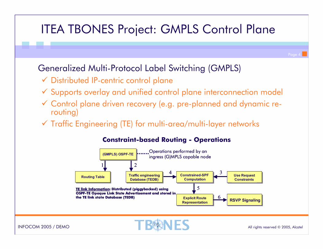
ITEA TBONES Project: GMPLS Control Plane
Generalized Multi-Protocol Label Switching (GMPLS)
� Distributed IP-centric control plane
� Supports overlay and unified control plane interconnection model
� Control plane driven recovery (e.g. pre-planned and dynamic re-routing)
� Traffic Engineering (TE) for multi-area/multi-layer networks
Constraint-based Routing - Operations
Use Request
Constraints
Constrained-SPF
Computation
Explicit Route
RepresentationRSVP Signaling
Routing Table
(GMPLS) OSPF-TE
Traffic engineering
Database (TEDB)
Operations performed by an ingress (G)MPLS capable node
1 2
3
6
4
5TE link Information: Distributed (piggybacked) using OSPF-TE Opaque Link State Advertisement and stored in the TE link state Database (TEDB)
Page 5
All rights reserved © 2005, AlcatelINFOCOM 2005 / DEMO
TBONES – GMPLS Control Plane Emulator
Emulates the behavior of a set of nodes by instantiating for each node, a lower protocol stack and several control plane controllers.
Each protocol stack implements IETF GMPLS protocol suite:
�Open Shortest Path First - Traffic Engineering (OSPF-TE)
� Resource reSerVation Protocol - Traffic Engineering (RSVP-TE)
Each control plane controller set runs in its own process, they communicate with each other through the protocol stacks
Each control plane controller consists of a set of modules:
� Node Emulator (NE)
� Signaling Controller (SIGC)
� TE Controller (TEC)
� Path Computation Controller (PCC)
Page 6
All rights reserved © 2005, AlcatelINFOCOM 2005 / DEMO
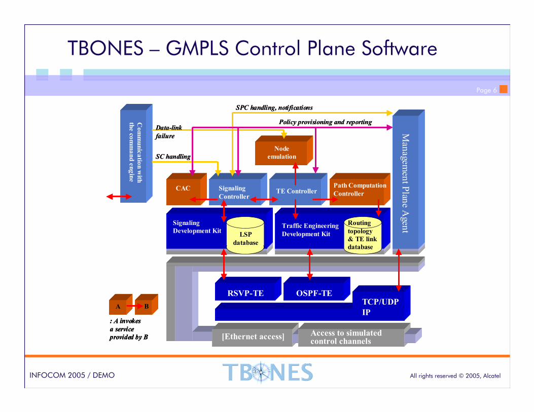
TBONES – GMPLS Control Plane Software
TE ControllerPath Computation
Controller
Signaling
Development KitTraffic Engineering
Development Kit
Routing
topology
& TE link
database
LSP
database
Communication with
the command engine
Node
emulation
CAC Signaling
Controller
A B
: A invokes
a service
provided by B
SPC handling, notifications
SC handling
Policy provisioning and reportingData-link
failure
TCP/UDP
IP
RSVP-TE OSPF-TE
[Ethernet access] Access to simulated control channels
Managem
ent Plane Agent
TE ControllerPath Computation
Controller
Signaling
Development KitTraffic Engineering
Development Kit
Routing
topology
& TE link
database
LSP
database
Communication with
the command engine
Node
emulation
CAC Signaling
Controller
A B
: A invokes
a service
provided by B
A B
: A invokes
a service
provided by B
SPC handling, notifications
SC handling
Policy provisioning and reportingData-link
failure
TCP/UDP
IP
RSVP-TE OSPF-TE
[Ethernet access] Access to simulated control channels
Managem
ent Plane Agent
Page 7
All rights reserved © 2005, AlcatelINFOCOM 2005 / DEMO
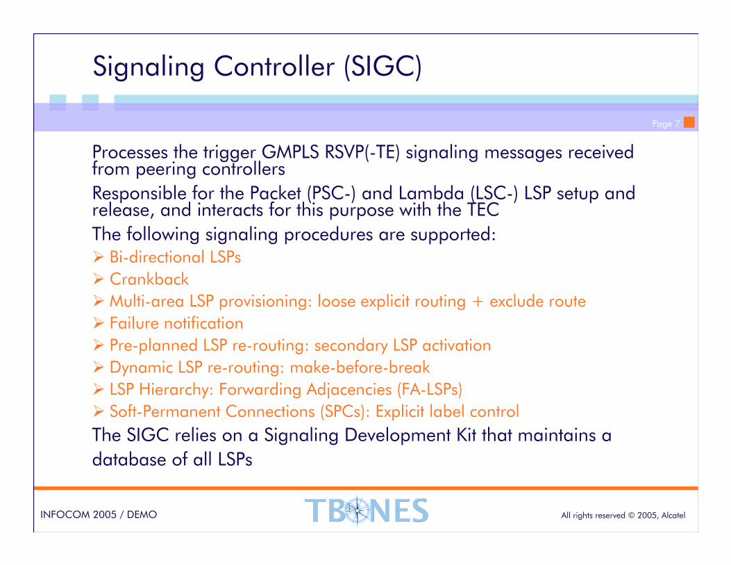
Signaling Controller (SIGC)
Processes the trigger GMPLS RSVP(-TE) signaling messages received from peering controllers
Responsible for the Packet (PSC-) and Lambda (LSC-) LSP setup and release, and interacts for this purpose with the TEC
The following signaling procedures are supported:� Bi-directional LSPs
� Crankback
�Multi-area LSP provisioning: loose explicit routing + exclude route
� Failure notification
� Pre-planned LSP re-routing: secondary LSP activation
� Dynamic LSP re-routing: make-before-break
� LSP Hierarchy: Forwarding Adjacencies (FA-LSPs)
� Soft-Permanent Connections (SPCs): Explicit label control
The SIGC relies on a Signaling Development Kit that maintains a
database of all LSPs
Page 8
All rights reserved © 2005, AlcatelINFOCOM 2005 / DEMO
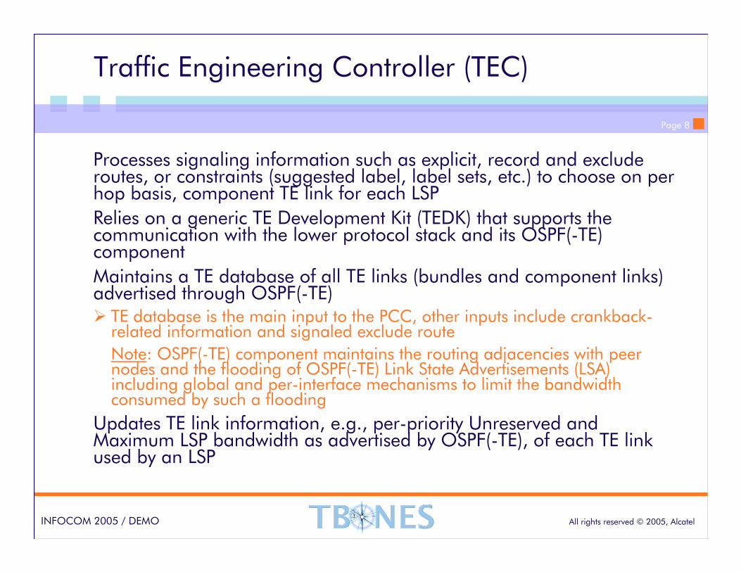
Traffic Engineering Controller (TEC)
Processes signaling information such as explicit, record and exclude routes, or constraints (suggested label, label sets, etc.) to choose on per hop basis, component TE link for each LSP
Relies on a generic TE Development Kit (TEDK) that supports the communication with the lower protocol stack and its OSPF(-TE) component
Maintains a TE database of all TE links (bundles and component links) advertised through OSPF(-TE) � TE database is the main input to the PCC, other inputs include crankback-
related information and signaled exclude route
Note: OSPF(-TE) component maintains the routing adjacencies with peer nodes and the flooding of OSPF(-TE) Link State Advertisements (LSA) including global and per-interface mechanisms to limit the bandwidth consumed by such a flooding
Updates TE link information, e.g., per-priority Unreserved and Maximum LSP bandwidth as advertised by OSPF(-TE), of each TE link used by an LSP
Page 9
All rights reserved © 2005, AlcatelINFOCOM 2005 / DEMO
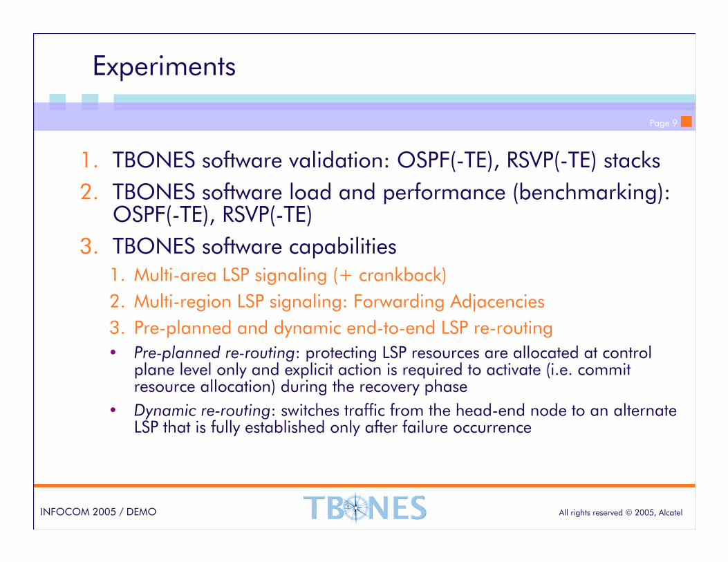
Experiments
1. TBONES software validation: OSPF(-TE), RSVP(-TE) stacks
2. TBONES software load and performance (benchmarking): OSPF(-TE), RSVP(-TE)
3. TBONES software capabilities1. Multi-area LSP signaling (+ crankback)
2. Multi-region LSP signaling: Forwarding Adjacencies
3. Pre-planned and dynamic end-to-end LSP re-routing
� Pre-planned re-routing: protecting LSP resources are allocated at control plane level only and explicit action is required to activate (i.e. commit resource allocation) during the recovery phase
� Dynamic re-routing: switches traffic from the head-end node to an alternate LSP that is fully established only after failure occurrence
Page 10
All rights reserved © 2005, AlcatelINFOCOM 2005 / DEMO
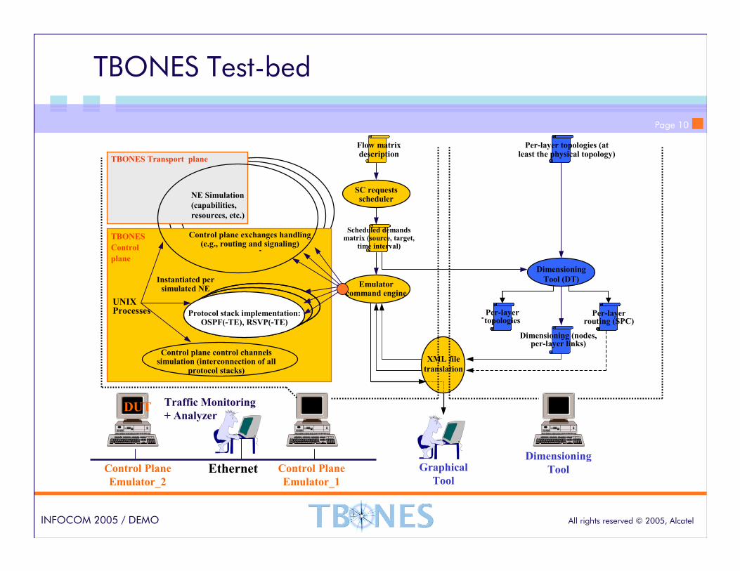
TBONES Test-bed
TBONES Transport plane
-
-Per-layer topologies
Ethernet
Flow matrix description
NE Simulation
(capabilities,
resources, etc.)
-
Per-layer topologies (at least the physical topology)
-
-
UNIX Processes
-
Traffic Monitoring
+ Analyzer
Control Plane
Emulator_2
DUT
Dimensioning
Tool
TBONES
Control
plane
XML file
translation
Per-layer routing (SPC)
Dimensioning (nodes, per-layer links)
SC requests scheduler
Protocol stack implementation: OSPF(-TE), RSVP(-TE)
Instantiated per simulated NE
Control plane control channels simulation (interconnection of all
protocol stacks)
Control plane exchanges handling (e.g., routing and signaling)
Emulator command engine
Scheduled demands matrix (source, target,
time interval)
Dimensioning
Tool (DT)
Graphical
ToolControl Plane
Emulator_1
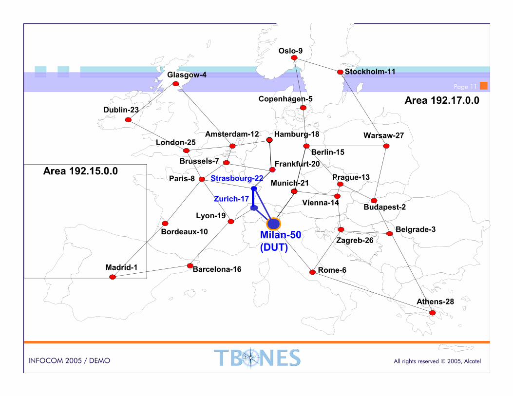
Page 11
All rights reserved © 2005, AlcatelINFOCOM 2005 / DEMO
Oslo-9
Stockholm-11
Copenhagen-5
Amsterdam-12
Dublin-23
London-25
Brussels-7
Paris-8
Madrid-1
Zurich-17
Milan-50
(DUT)
Berlin-15
Athens-28
Budapest-2Vienna-14
Prague-13
Warsaw-27
Munich-21
Rome-6
Hamburg-18
Barcelona-16
Bordeaux-10
Lyon-19
Frankfurt-20
Glasgow-4
Belgrade-3
Strasbourg-22
Zagreb-26
Area 192.15.0.0
Area 192.17.0.0
Page 12
All rights reserved © 2005, AlcatelINFOCOM 2005 / DEMO
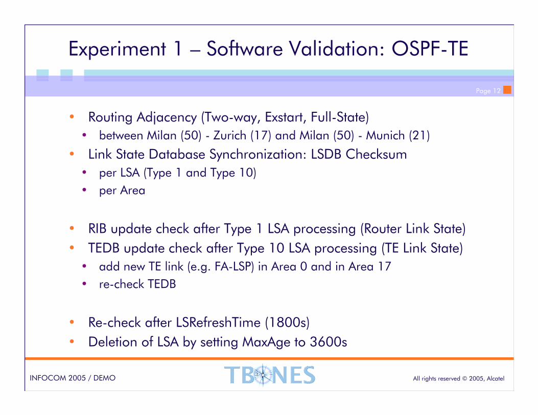
Experiment 1 – Software Validation: OSPF-TE
• Routing Adjacency (Two-way, Exstart, Full-State)
• between Milan (50) - Zurich (17) and Milan (50) - Munich (21)
• Link State Database Synchronization: LSDB Checksum
• per LSA (Type 1 and Type 10)
• per Area
• RIB update check after Type 1 LSA processing (Router Link State)
• TEDB update check after Type 10 LSA processing (TE Link State)
• add new TE link (e.g. FA-LSP) in Area 0 and in Area 17
• re-check TEDB
• Re-check after LSRefreshTime (1800s)
• Deletion of LSA by setting MaxAge to 3600s
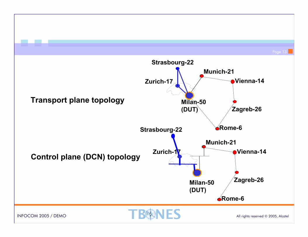
Page 13
All rights reserved © 2005, AlcatelINFOCOM 2005 / DEMO
Zurich-17
Milan-50
(DUT)
Strasbourg-22
Munich-21
Transport plane topology
Control plane (DCN) topology
Rome-6
Vienna-14
Zagreb-26
Zurich-17
Milan-50
(DUT)
Strasbourg-22
Munich-21
Rome-6
Vienna-14
Zagreb-26
Page 14
All rights reserved © 2005, AlcatelINFOCOM 2005 / DEMO
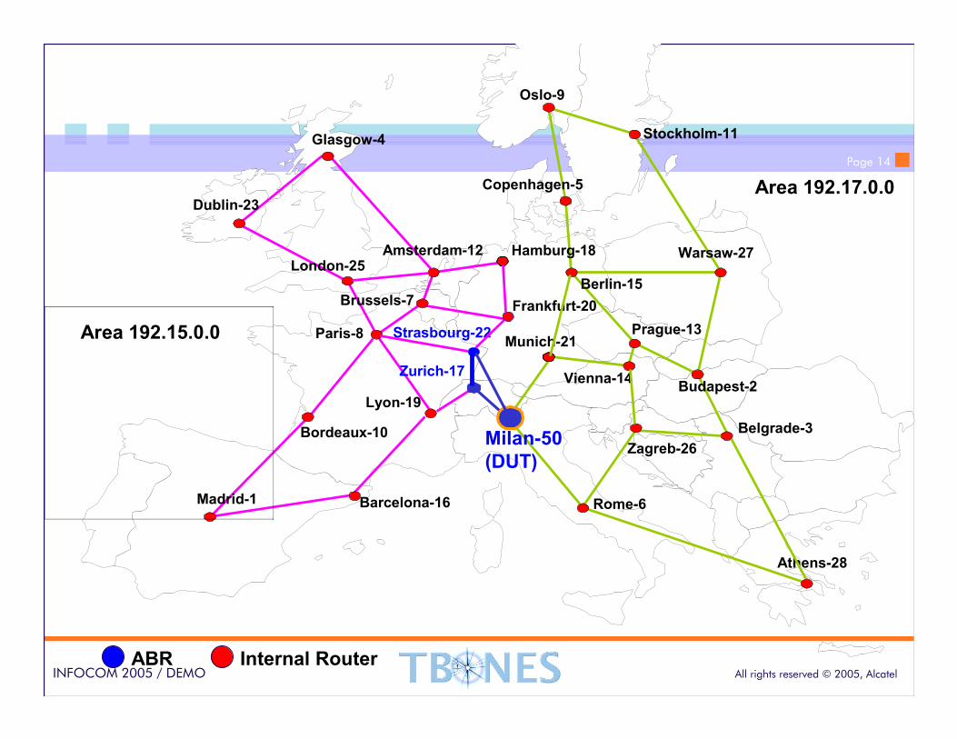
Prague-13
Oslo-9
Stockholm-11
Copenhagen-5
Amsterdam-12
Dublin-23
London-25
Brussels-7
Paris-8
Madrid-1
Zurich-17
Milan-50
(DUT)
Berlin-15
Athens-28
Budapest-2Vienna-14
Warsaw-27
Munich-21
Rome-6
Hamburg-18
Barcelona-16
Bordeaux-10
Lyon-19
Frankfurt-20
Glasgow-4
Belgrade-3
Strasbourg-22
Zagreb-26
Area 192.15.0.0
Area 192.17.0.0
ABR Internal Router
Prague-13
Page 15
All rights reserved © 2005, AlcatelINFOCOM 2005 / DEMO
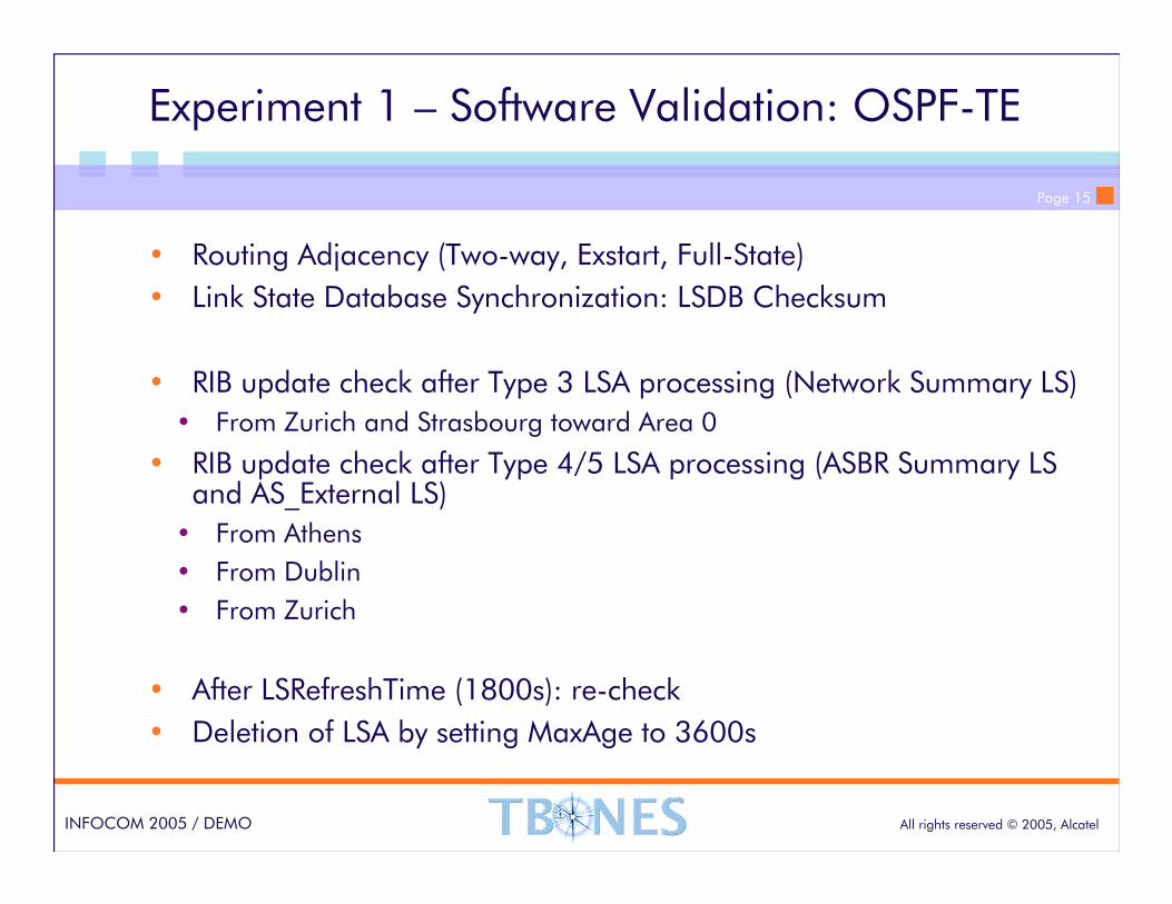
Experiment 1 – Software Validation: OSPF-TE
• Routing Adjacency (Two-way, Exstart, Full-State)
• Link State Database Synchronization: LSDB Checksum
• RIB update check after Type 3 LSA processing (Network Summary LS)
• From Zurich and Strasbourg toward Area 0
• RIB update check after Type 4/5 LSA processing (ASBR Summary LS and AS_External LS)
• From Athens
• From Dublin
• From Zurich
• After LSRefreshTime (1800s): re-check
• Deletion of LSA by setting MaxAge to 3600s
Page 16
All rights reserved © 2005, AlcatelINFOCOM 2005 / DEMO
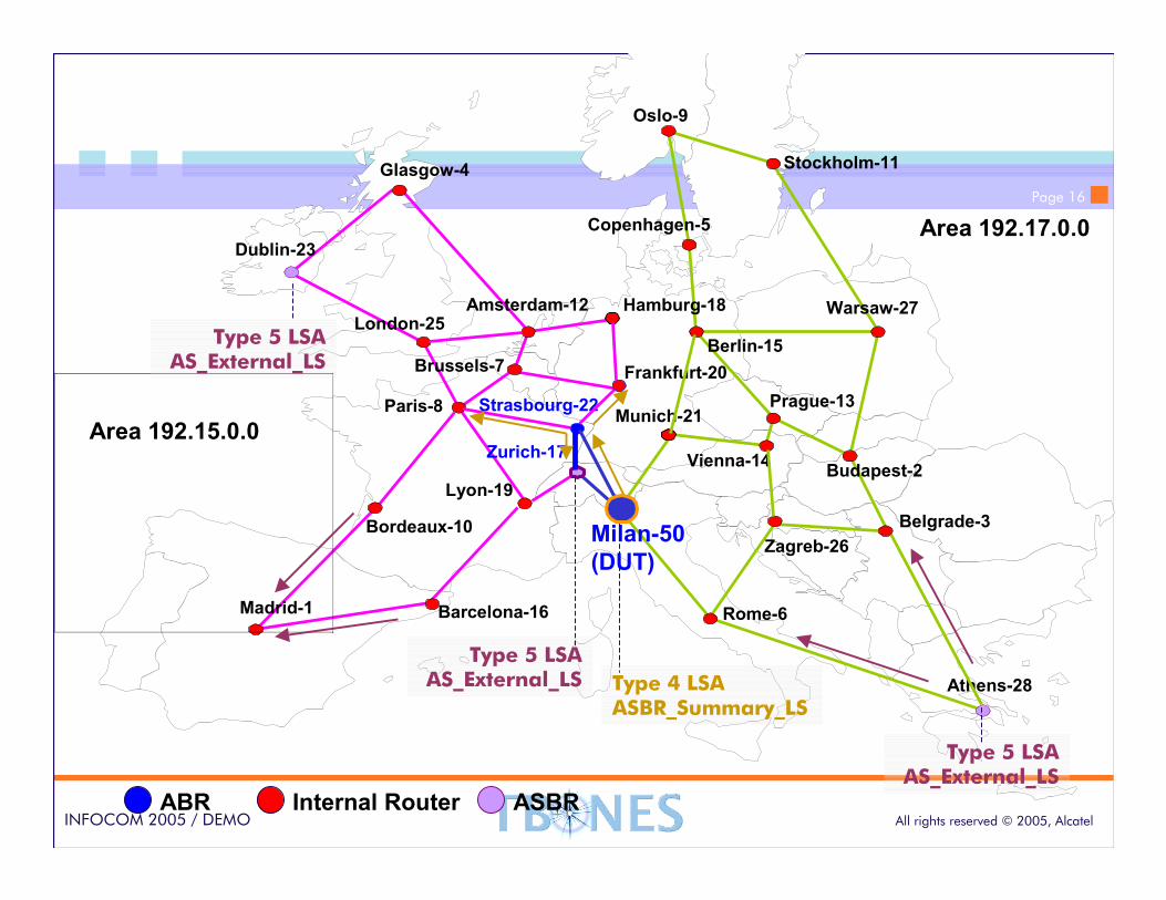
Prague-13
Oslo-9
Stockholm-11
Copenhagen-5
Amsterdam-12
Dublin-23
London-25
Brussels-7
Paris-8
Madrid-1
Zurich-17
Milan-50
(DUT)
Berlin-15
Athens-28
Budapest-2Vienna-14
Warsaw-27
Munich-21
Rome-6
Hamburg-18
Barcelona-16
Bordeaux-10
Lyon-19
Frankfurt-20
Glasgow-4
Belgrade-3
Strasbourg-22
Zagreb-26
Area 192.15.0.0
Area 192.17.0.0
ABR Internal Router
Prague-13
Type 5 LSA AS_External_LS
Type 5 LSA AS_External_LS
Type 5 LSA AS_External_LS
ASBR
Type 4 LSA ASBR_Summary_LS
Page 17
All rights reserved © 2005, AlcatelINFOCOM 2005 / DEMO
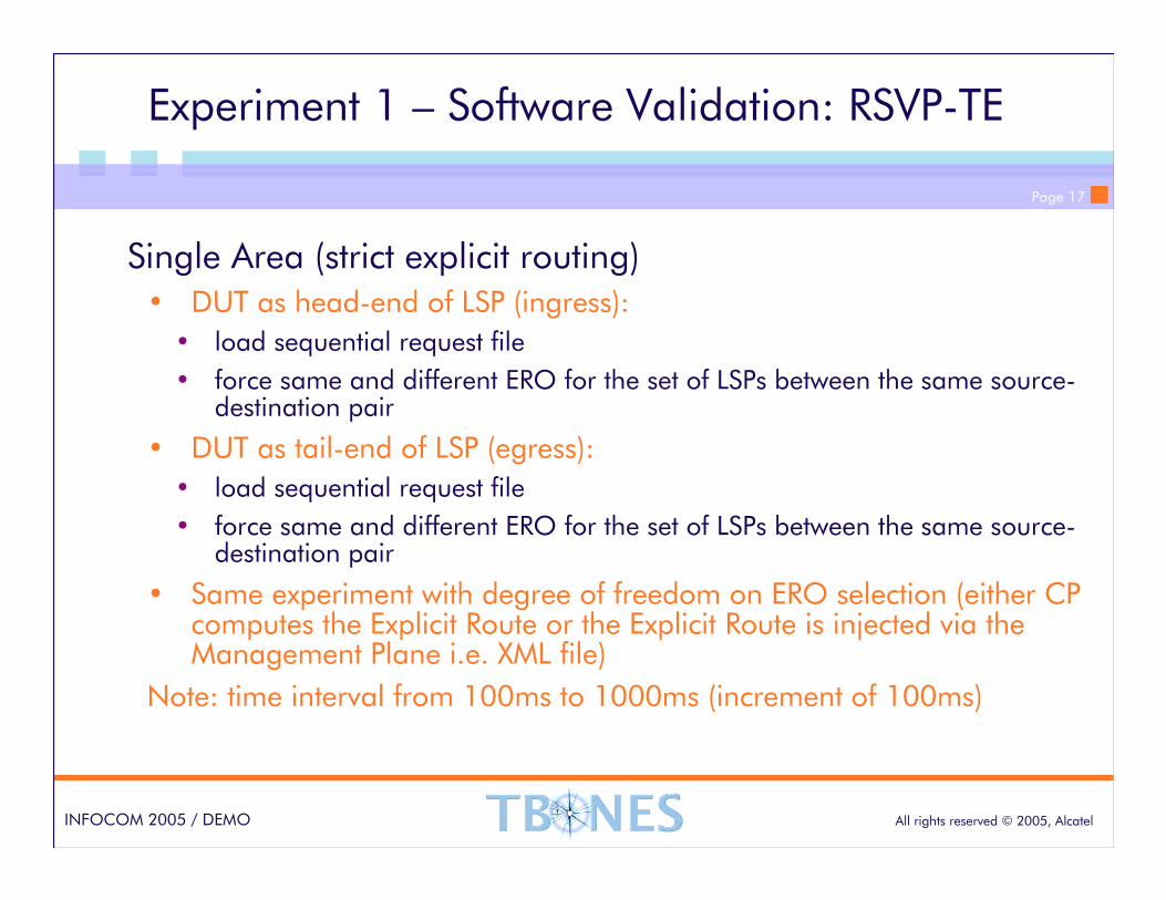
Experiment 1 – Software Validation: RSVP-TE
Single Area (strict explicit routing)• DUT as head-end of LSP (ingress):
• load sequential request file
• force same and different ERO for the set of LSPs between the same source-destination pair
• DUT as tail-end of LSP (egress):
• load sequential request file
• force same and different ERO for the set of LSPs between the same source-destination pair
• Same experiment with degree of freedom on ERO selection (either CP computes the Explicit Route or the Explicit Route is injected via the Management Plane i.e. XML file)
Note: time interval from 100ms to 1000ms (increment of 100ms)
Page 18
All rights reserved © 2005, AlcatelINFOCOM 2005 / DEMO
Experiment 1 – Software Validation: RSVP-TE
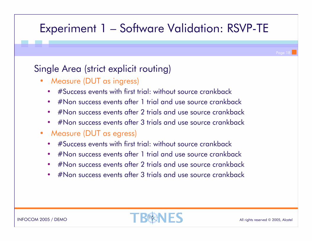
Single Area (strict explicit routing)• Measure (DUT as ingress)
• #Success events with first trial: without source crankback
• #Non success events after 1 trial and use source crankback
• #Non success events after 2 trials and use source crankback
• #Non success events after 3 trials and use source crankback
• Measure (DUT as egress)
• #Success events with first trial: without source crankback
• #Non success events after 1 trial and use source crankback
• #Non success events after 2 trials and use source crankback
• #Non success events after 3 trials and use source crankback
Page 19
All rights reserved © 2005, AlcatelINFOCOM 2005 / DEMO
Experiment 1 – Software Validation: RSVP-TE
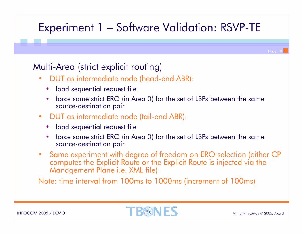
Multi-Area (strict explicit routing)• DUT as intermediate node (head-end ABR):
• load sequential request file
• force same strict ERO (in Area 0) for the set of LSPs between the same source-destination pair
• DUT as intermediate node (tail-end ABR):
• load sequential request file
• force same strict ERO (in Area 0) for the set of LSPs between the same source-destination pair
• Same experiment with degree of freedom on ERO selection (either CP computes the Explicit Route or the Explicit Route is injected via the Management Plane i.e. XML file)
Note: time interval from 100ms to 1000ms (increment of 100ms)
Page 20
All rights reserved © 2005, AlcatelINFOCOM 2005 / DEMO
Experiment 1 – Software Validation: RSVP-TE
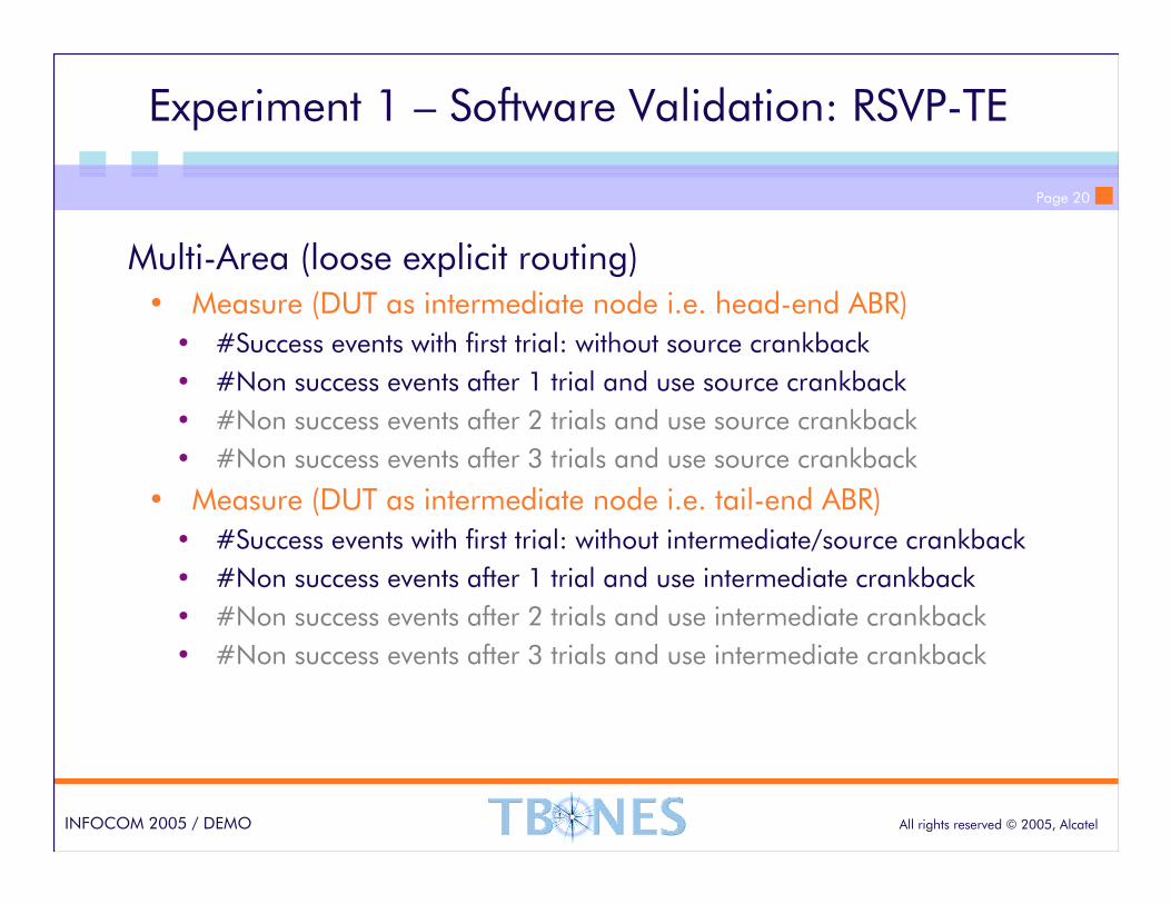
Multi-Area (loose explicit routing)• Measure (DUT as intermediate node i.e. head-end ABR)
• #Success events with first trial: without source crankback
• #Non success events after 1 trial and use source crankback
• #Non success events after 2 trials and use source crankback
• #Non success events after 3 trials and use source crankback
• Measure (DUT as intermediate node i.e. tail-end ABR)
• #Success events with first trial: without intermediate/source crankback
• #Non success events after 1 trial and use intermediate crankback
• #Non success events after 2 trials and use intermediate crankback
• #Non success events after 3 trials and use intermediate crankback
Page 21
All rights reserved © 2005, AlcatelINFOCOM 2005 / DEMO
Experiment 2 – Software Performance: OSPF-TE
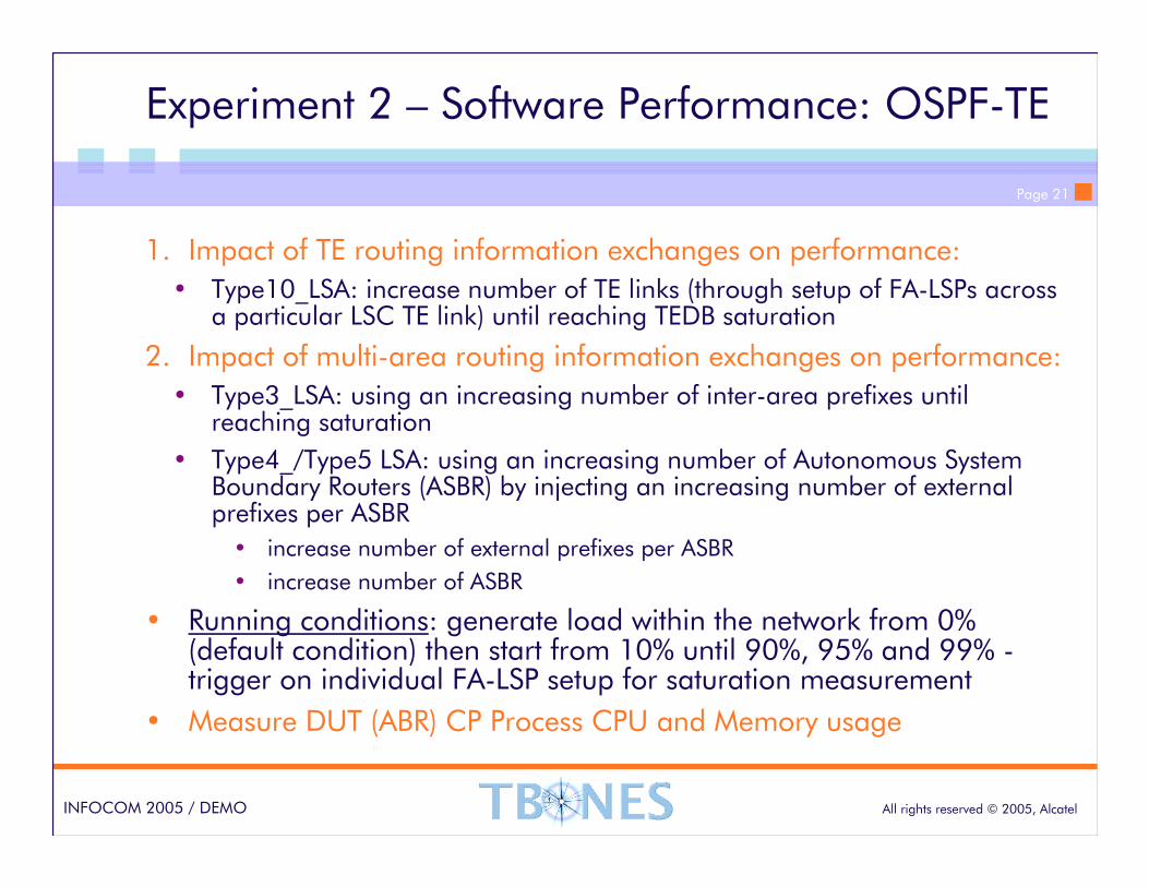
1. Impact of TE routing information exchanges on performance:
• Type10_LSA: increase number of TE links (through setup of FA-LSPs across a particular LSC TE link) until reaching TEDB saturation
2. Impact of multi-area routing information exchanges on performance:
• Type3_LSA: using an increasing number of inter-area prefixes until reaching saturation
• Type4_/Type5 LSA: using an increasing number of Autonomous System Boundary Routers (ASBR) by injecting an increasing number of external prefixes per ASBR
• increase number of external prefixes per ASBR
• increase number of ASBR
• Running conditions: generate load within the network from 0% (default condition) then start from 10% until 90%, 95% and 99% -trigger on individual FA-LSP setup for saturation measurement
• Measure DUT (ABR) CP Process CPU and Memory usage
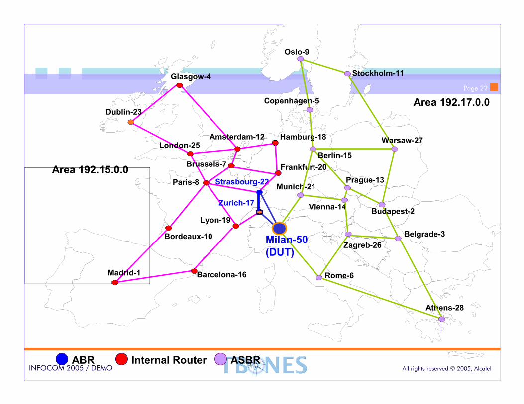
Page 22
All rights reserved © 2005, AlcatelINFOCOM 2005 / DEMO
Prague-13
Oslo-9
Stockholm-11
Copenhagen-5
Amsterdam-12
Dublin-23
London-25
Brussels-7
Paris-8
Madrid-1
Zurich-17
Milan-50
(DUT)
Berlin-15
Athens-28
Budapest-2Vienna-14
Warsaw-27
Munich-21
Rome-6
Hamburg-18
Barcelona-16
Bordeaux-10
Lyon-19
Frankfurt-20
Glasgow-4
Belgrade-3
Strasbourg-22
Zagreb-26
Area 192.15.0.0
Area 192.17.0.0
ABR Internal Router
Prague-13
ASBR
Page 23
All rights reserved © 2005, AlcatelINFOCOM 2005 / DEMO
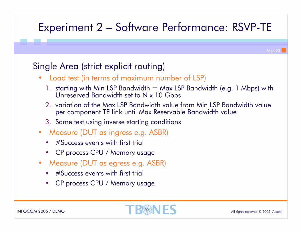
Experiment 2 – Software Performance: RSVP-TE
Single Area (strict explicit routing)• Load test (in terms of maximum number of LSP)
1. starting with Min LSP Bandwidth = Max LSP Bandwidth (e.g. 1 Mbps) with Unreserved Bandwidth set to N x 10 Gbps
2. variation of the Max LSP Bandwidth value from Min LSP Bandwidth value per component TE link until Max Reservable Bandwidth value
3. Same test using inverse starting conditions
• Measure (DUT as ingress e.g. ASBR)
• #Success events with first trial
• CP process CPU / Memory usage
• Measure (DUT as egress e.g. ASBR)
• #Success events with first trial
• CP process CPU / Memory usage
Page 24
All rights reserved © 2005, AlcatelINFOCOM 2005 / DEMO
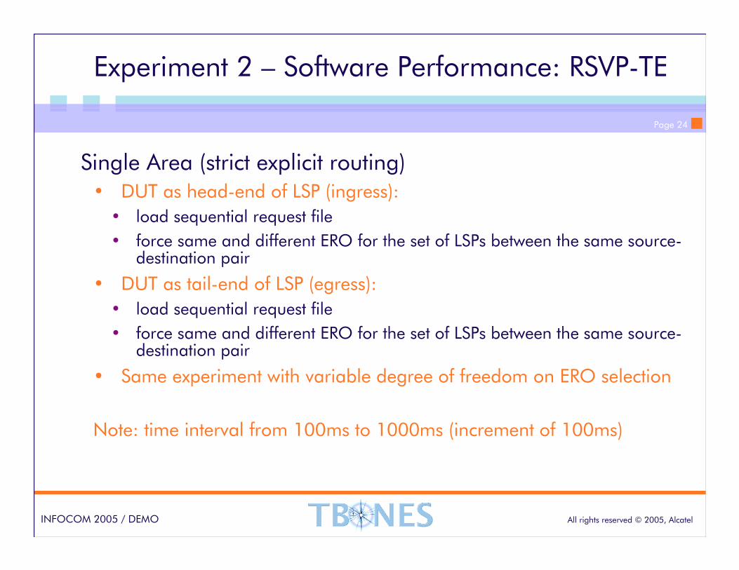
Experiment 2 – Software Performance: RSVP-TE
Single Area (strict explicit routing)• DUT as head-end of LSP (ingress):
• load sequential request file
• force same and different ERO for the set of LSPs between the same source-destination pair
• DUT as tail-end of LSP (egress):
• load sequential request file
• force same and different ERO for the set of LSPs between the same source-destination pair
• Same experiment with variable degree of freedom on ERO selection
Note: time interval from 100ms to 1000ms (increment of 100ms)
Page 25
All rights reserved © 2005, AlcatelINFOCOM 2005 / DEMO
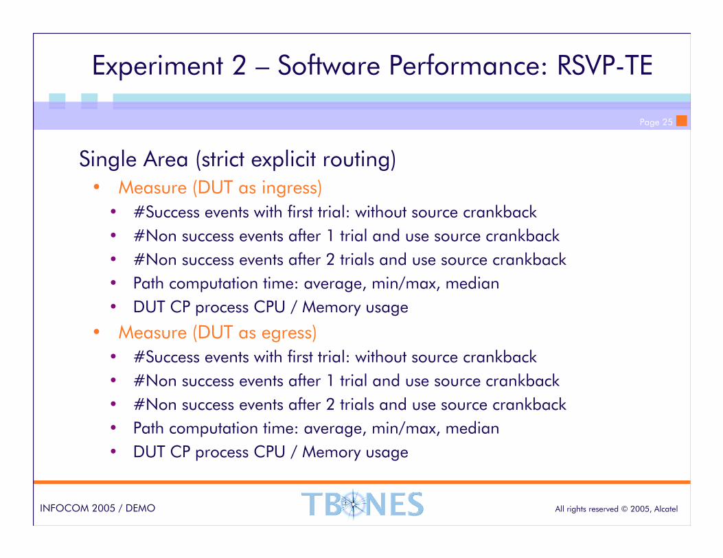
Experiment 2 – Software Performance: RSVP-TE
Single Area (strict explicit routing)• Measure (DUT as ingress)
• #Success events with first trial: without source crankback
• #Non success events after 1 trial and use source crankback
• #Non success events after 2 trials and use source crankback
• Path computation time: average, min/max, median
• DUT CP process CPU / Memory usage
• Measure (DUT as egress)
• #Success events with first trial: without source crankback
• #Non success events after 1 trial and use source crankback
• #Non success events after 2 trials and use source crankback
• Path computation time: average, min/max, median
• DUT CP process CPU / Memory usage

Page 26
All rights reserved © 2005, AlcatelINFOCOM 2005 / DEMO
Experiment 2 – Software Performance: RSVP-TE
Multi-Area (loose explicit routing)• DUT as head-end of LSP (ingress):
• load sequential request file
• force same and different ERO for the set of LSPs between the same source-destination pair
• DUT as tail-end of LSP (egress):
• load sequential request file
• force same and different ERO for the set of LSPs between the same source-destination pair
• Same experiment with variable degree of freedom on ERO selection
Note: time interval from 100ms to 1000ms (increment of 100ms)
Page 27
All rights reserved © 2005, AlcatelINFOCOM 2005 / DEMO
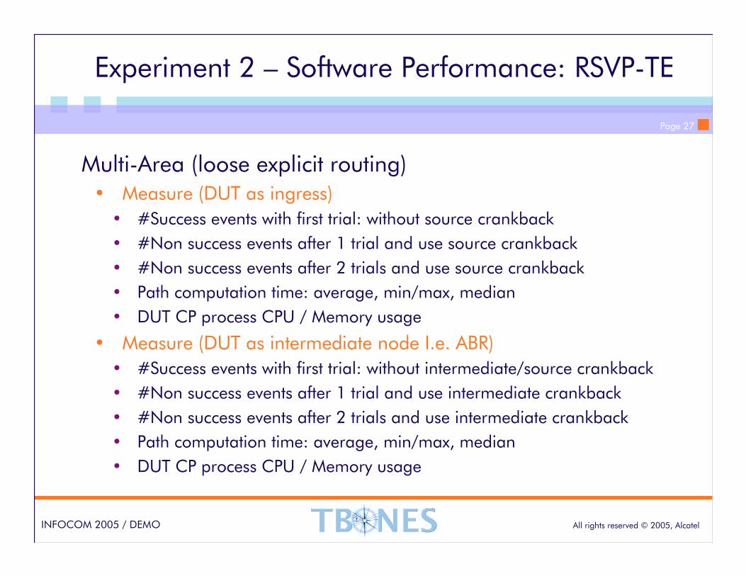
Experiment 2 – Software Performance: RSVP-TE
Multi-Area (loose explicit routing)• Measure (DUT as ingress)
• #Success events with first trial: without source crankback
• #Non success events after 1 trial and use source crankback
• #Non success events after 2 trials and use source crankback
• Path computation time: average, min/max, median
• DUT CP process CPU / Memory usage
• Measure (DUT as intermediate node I.e. ABR)
• #Success events with first trial: without intermediate/source crankback
• #Non success events after 1 trial and use intermediate crankback
• #Non success events after 2 trials and use intermediate crankback
• Path computation time: average, min/max, median
• DUT CP process CPU / Memory usage
Page 28
All rights reserved © 2005, AlcatelINFOCOM 2005 / DEMO
Experiments 3: TBONES software capabilities
TBONES software capabilities1. Multi-area LSP signaling (+ crankback)
2. Multi-region LSP signaling: Forwarding Adjacencies
3. Pre-planned and dynamic end-to-end LSP re-routing
� Pre-planned re-routing: protecting LSP resources are allocated at control plane level only and explicit action is required to activate (i.e. commit resource allocation) during the recovery phase
� Dynamic re-routing: switches traffic from the head-end node to an alternate LSP that is fully established only after failure occurrence
Page 29
All rights reserved © 2005, AlcatelINFOCOM 2005 / DEMO
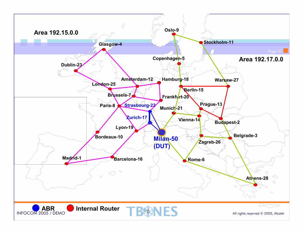
Experiment 3 – Multi-Region LSP Signaling
Single Area (strict explicit routing)• DUT as head-end of the FA-LSP (nesting LSC LSP):
• load sequential request file
• force same and different (strict/loose) ERO for the set of PSC LSPs between the same source-destination pair
• DUT as tail-end of the FA-LSP (nesting LSC LSP):
• load sequential request file
• force same and different (strict/loose) ERO for the set of PSC LSPs between the same source-destination pair
• Same experiment with variable degree of freedom on ERO selection
Note: time interval from 100ms to 1000ms (increment of 100ms)
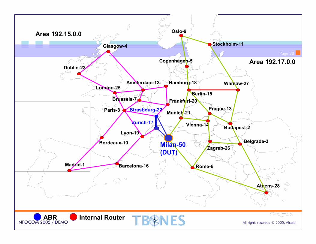
Page 30
All rights reserved © 2005, AlcatelINFOCOM 2005 / DEMO
Prague-13
Oslo-9
Stockholm-11
Copenhagen-5
Amsterdam-12
Dublin-23
London-25
Brussels-7
Paris-8
Madrid-1
Zurich-17
Milan-50
(DUT)
Berlin-15
Athens-28
Budapest-2Vienna-14
Warsaw-27
Munich-21
Rome-6
Hamburg-18
Barcelona-16
Bordeaux-10
Lyon-19
Frankfurt-20
Glasgow-4
Belgrade-3
Strasbourg-22
Zagreb-26
Area 192.15.0.0
Area 192.17.0.0
ABR Internal Router
Prague-13
Page 31
All rights reserved © 2005, AlcatelINFOCOM 2005 / DEMO
Prague-13
Oslo-9
Stockholm-11
Copenhagen-5
Amsterdam-12
Dublin-23
London-25
Brussels-7
Paris-8
Madrid-1
Zurich-17
Milan-50
(DUT)
Berlin-15
Athens-28
Budapest-2Vienna-14
Warsaw-27
Munich-21
Rome-6
Hamburg-18
Barcelona-16
Bordeaux-10
Lyon-19
Frankfurt-20
Glasgow-4
Belgrade-3
Strasbourg-22
Zagreb-26
Area 192.15.0.0
Area 192.17.0.0
ABR Internal Router
Prague-13
Page 32
All rights reserved © 2005, AlcatelINFOCOM 2005 / DEMO
Prague-13
Oslo-9
Stockholm-11
Copenhagen-5
Amsterdam-12
Dublin-23
London-25
Brussels-7
Paris-8
Madrid-1
Zurich-17
Milan-50
(DUT)
Berlin-15
Athens-28
Budapest-2Vienna-14
Warsaw-27
Munich-21
Rome-6
Hamburg-18
Barcelona-16
Bordeaux-10
Lyon-19
Frankfurt-20
Glasgow-4
Belgrade-3
Strasbourg-22
Zagreb-26
Area 192.15.0.0
Area 192.17.0.0
ABR Internal Router
Prague-13
Page 33
All rights reserved © 2005, AlcatelINFOCOM 2005 / DEMO
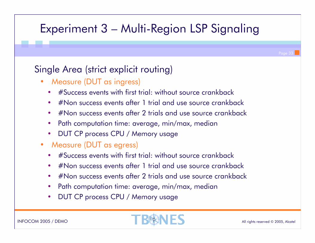
Experiment 3 – Multi-Region LSP Signaling
Single Area (strict explicit routing)• Measure (DUT as ingress)
• #Success events with first trial: without source crankback
• #Non success events after 1 trial and use source crankback
• #Non success events after 2 trials and use source crankback
• Path computation time: average, min/max, median
• DUT CP process CPU / Memory usage
• Measure (DUT as egress)
• #Success events with first trial: without source crankback
• #Non success events after 1 trial and use source crankback
• #Non success events after 2 trials and use source crankback
• Path computation time: average, min/max, median
• DUT CP process CPU / Memory usage
Page 34
All rights reserved © 2005, AlcatelINFOCOM 2005 / DEMO
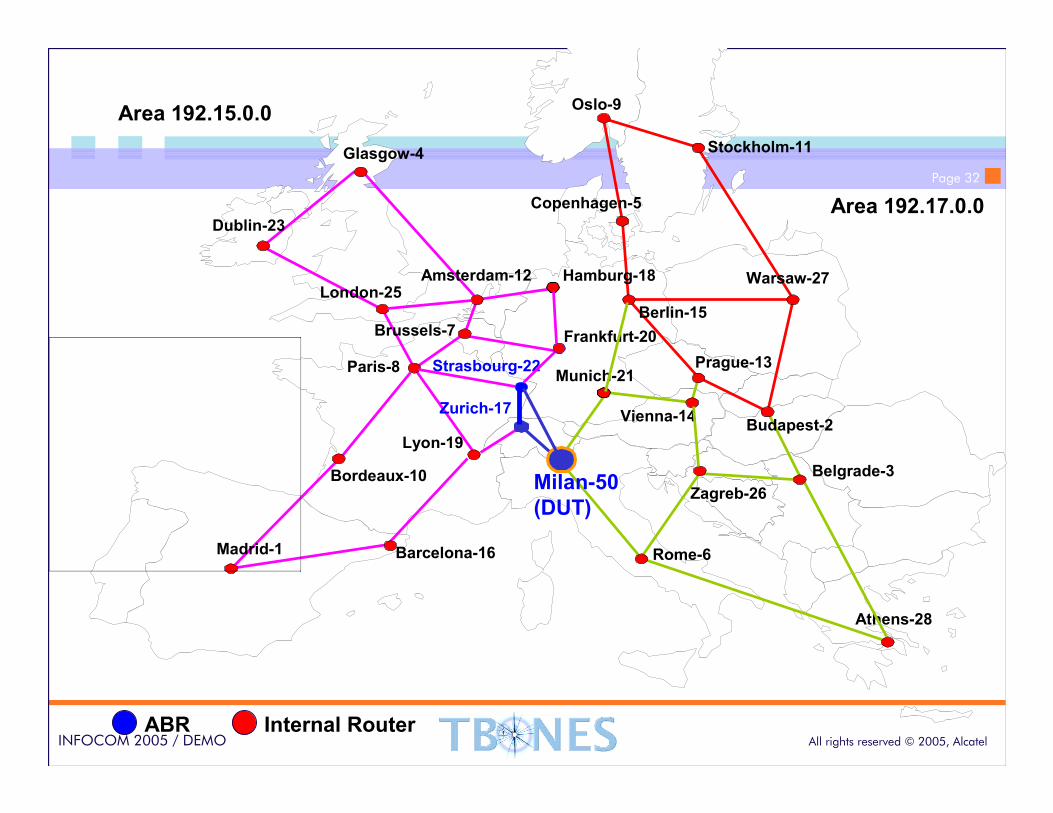
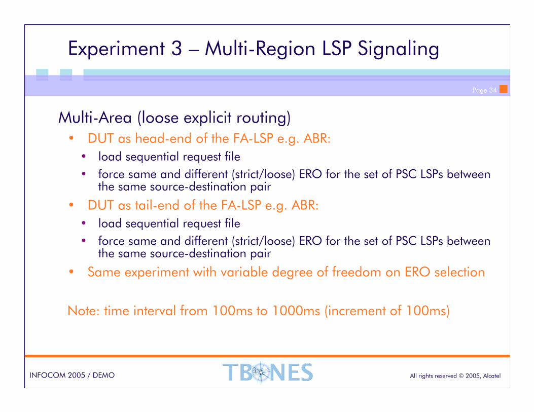
Experiment 3 – Multi-Region LSP Signaling
Multi-Area (loose explicit routing)• DUT as head-end of the FA-LSP e.g. ABR:
• load sequential request file
• force same and different (strict/loose) ERO for the set of PSC LSPs between the same source-destination pair
• DUT as tail-end of the FA-LSP e.g. ABR:
• load sequential request file
• force same and different (strict/loose) ERO for the set of PSC LSPs between the same source-destination pair
• Same experiment with variable degree of freedom on ERO selection
Note: time interval from 100ms to 1000ms (increment of 100ms)
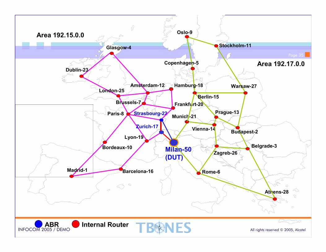
Page 35
All rights reserved © 2005, AlcatelINFOCOM 2005 / DEMO
Prague-13
Oslo-9
Stockholm-11
Copenhagen-5
Amsterdam-12
Dublin-23
London-25
Brussels-7
Paris-8
Madrid-1
Zurich-17
Milan-50
(DUT)
Berlin-15
Athens-28
Budapest-2Vienna-14
Warsaw-27
Munich-21
Rome-6
Hamburg-18
Barcelona-16
Bordeaux-10
Lyon-19
Frankfurt-20
Glasgow-4
Belgrade-3
Strasbourg-22
Zagreb-26
Area 192.15.0.0
Area 192.17.0.0
ABR Internal Router
Prague-13

Page 36
All rights reserved © 2005, AlcatelINFOCOM 2005 / DEMO
Prague-13
Oslo-9
Stockholm-11
Copenhagen-5
Amsterdam-12
Dublin-23
London-25
Brussels-7
Paris-8
Madrid-1
Zurich-17
Milan-50
(DUT)
Berlin-15
Athens-28
Budapest-2Vienna-14
Warsaw-27
Munich-21
Rome-6
Hamburg-18
Barcelona-16
Bordeaux-10
Lyon-19
Frankfurt-20
Glasgow-4
Belgrade-3
Strasbourg-22
Zagreb-26
Area 192.15.0.0
Area 192.17.0.0
ABR Internal Router
Prague-13

Page 37
All rights reserved © 2005, AlcatelINFOCOM 2005 / DEMO
Prague-13
Oslo-9
Stockholm-11
Copenhagen-5
Amsterdam-12
Dublin-23
London-25
Brussels-7
Paris-8
Madrid-1
Zurich-17
Milan-50
(DUT)
Berlin-15
Athens-28
Budapest-2Vienna-14
Warsaw-27
Munich-21
Rome-6
Hamburg-18
Barcelona-16
Bordeaux-10
Lyon-19
Frankfurt-20
Glasgow-4
Belgrade-3
Strasbourg-22
Zagreb-26
Area 192.15.0.0
Area 192.17.0.0
ABR Internal Router
Prague-13
Page 38
All rights reserved © 2005, AlcatelINFOCOM 2005 / DEMO
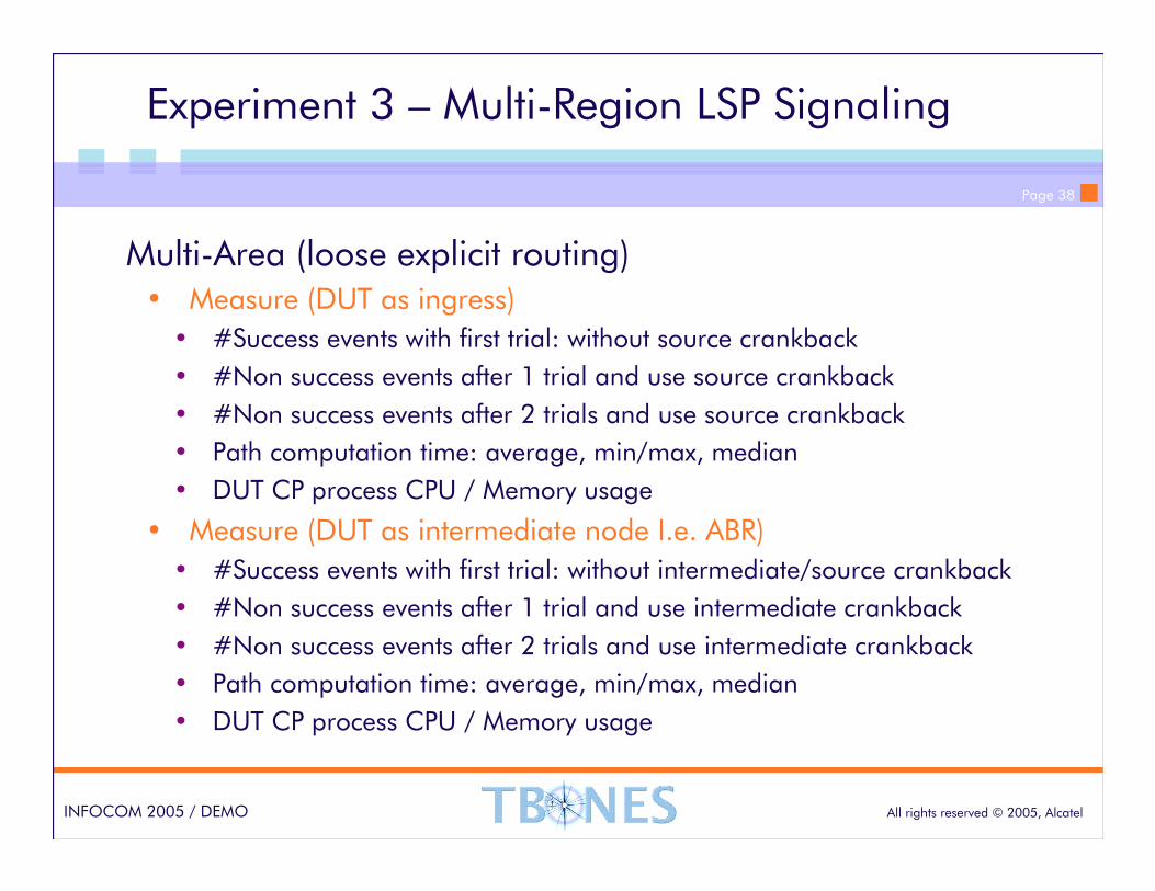
Experiment 3 – Multi-Region LSP Signaling
Multi-Area (loose explicit routing)• Measure (DUT as ingress)
• #Success events with first trial: without source crankback
• #Non success events after 1 trial and use source crankback
• #Non success events after 2 trials and use source crankback
• Path computation time: average, min/max, median
• DUT CP process CPU / Memory usage
• Measure (DUT as intermediate node I.e. ABR)
• #Success events with first trial: without intermediate/source crankback
• #Non success events after 1 trial and use intermediate crankback
• #Non success events after 2 trials and use intermediate crankback
• Path computation time: average, min/max, median
• DUT CP process CPU / Memory usage
Page 39
All rights reserved © 2005, AlcatelINFOCOM 2005 / DEMO
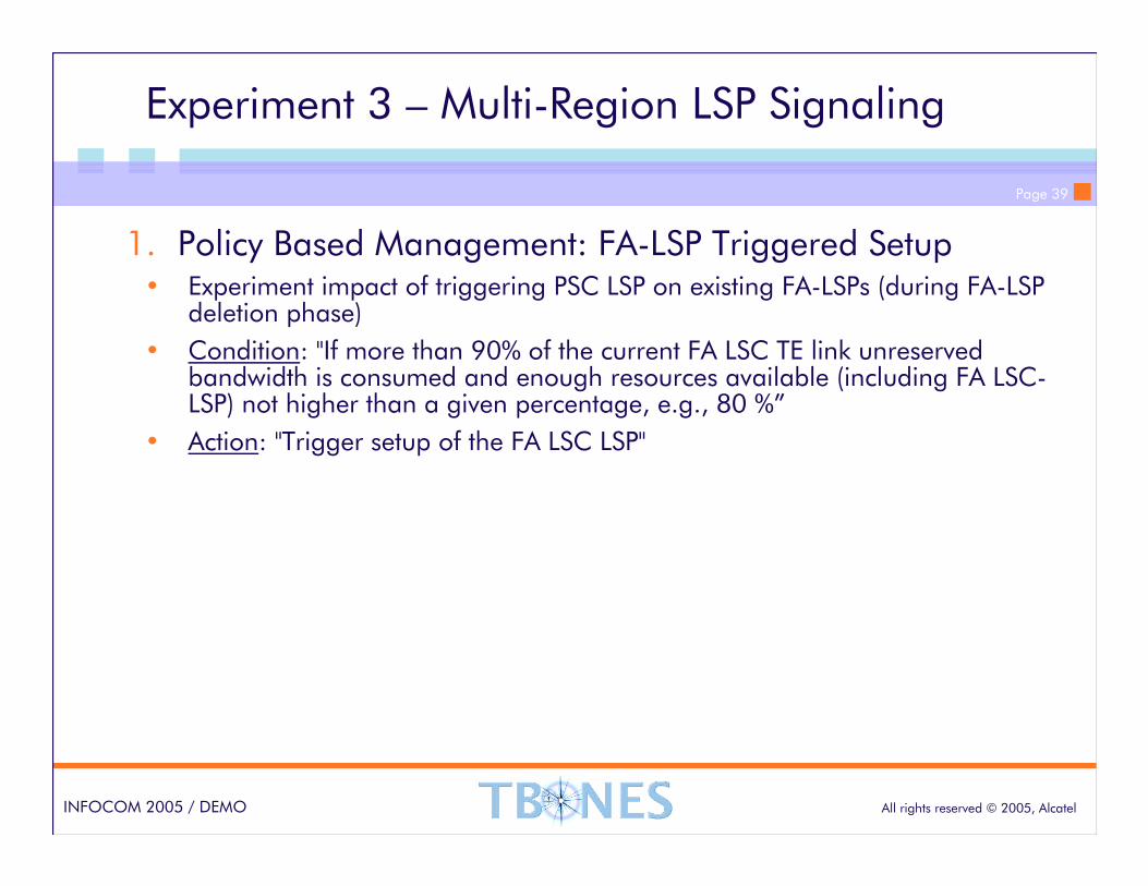
Experiment 3 – Multi-Region LSP Signaling
1. Policy Based Management: FA-LSP Triggered Setup• Experiment impact of triggering PSC LSP on existing FA-LSPs (during FA-LSP
deletion phase)
• Condition: "If more than 90% of the current FA LSC TE link unreserved bandwidth is consumed and enough resources available (including FA LSC-LSP) not higher than a given percentage, e.g., 80 %”
• Action: "Trigger setup of the FA LSC LSP"
Page 40
All rights reserved © 2005, AlcatelINFOCOM 2005 / DEMO
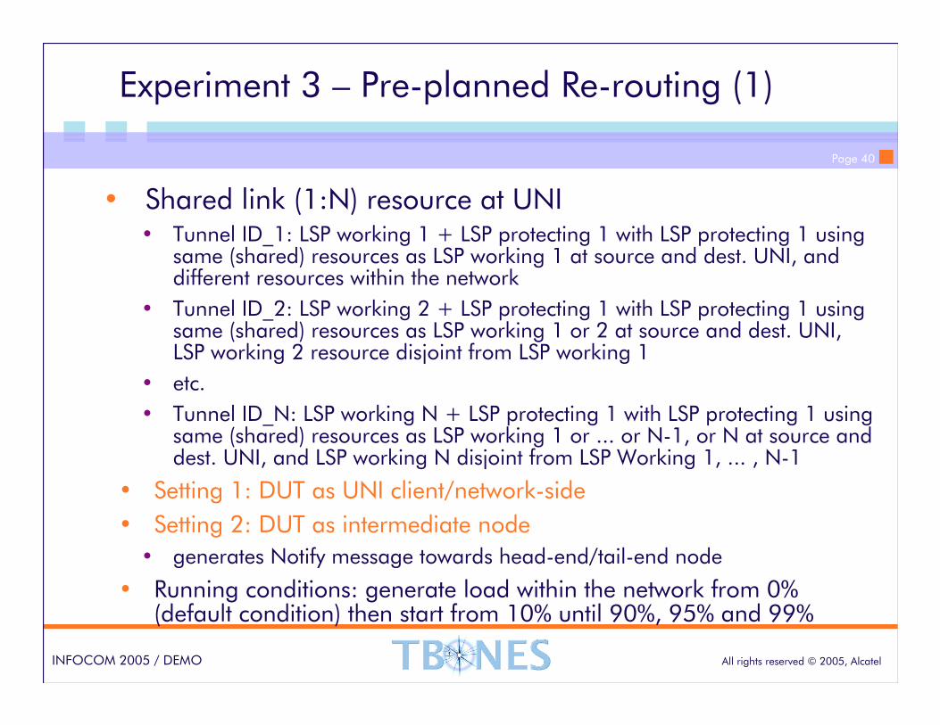
Experiment 3 – Pre-planned Re-routing (1)
• Shared link (1:N) resource at UNI• Tunnel ID_1: LSP working 1 + LSP protecting 1 with LSP protecting 1 using
same (shared) resources as LSP working 1 at source and dest. UNI, and different resources within the network
• Tunnel ID_2: LSP working 2 + LSP protecting 1 with LSP protecting 1 using same (shared) resources as LSP working 1 or 2 at source and dest. UNI, LSP working 2 resource disjoint from LSP working 1
• etc.
• Tunnel ID_N: LSP working N + LSP protecting 1 with LSP protecting 1 using same (shared) resources as LSP working 1 or ... or N-1, or N at source and dest. UNI, and LSP working N disjoint from LSP Working 1, ... , N-1
• Setting 1: DUT as UNI client/network-side
• Setting 2: DUT as intermediate node
• generates Notify message towards head-end/tail-end node
• Running conditions: generate load within the network from 0% (default condition) then start from 10% until 90%, 95% and 99%
Page 41
All rights reserved © 2005, AlcatelINFOCOM 2005 / DEMO
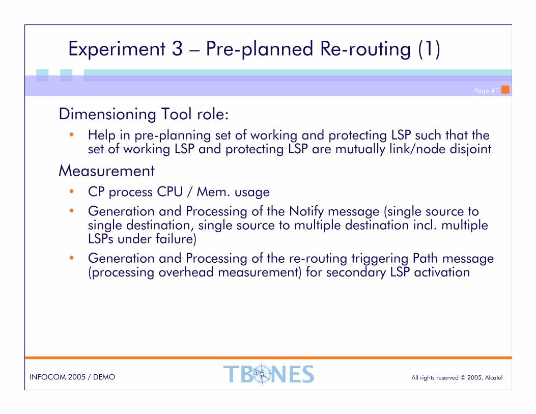
Experiment 3 – Pre-planned Re-routing (1)
Dimensioning Tool role:• Help in pre-planning set of working and protecting LSP such that the
set of working LSP and protecting LSP are mutually link/node disjoint
Measurement• CP process CPU / Mem. usage
• Generation and Processing of the Notify message (single source to single destination, single source to multiple destination incl. multiple LSPs under failure)
• Generation and Processing of the re-routing triggering Path message (processing overhead measurement) for secondary LSP activation
Page 42
All rights reserved © 2005, AlcatelINFOCOM 2005 / DEMO
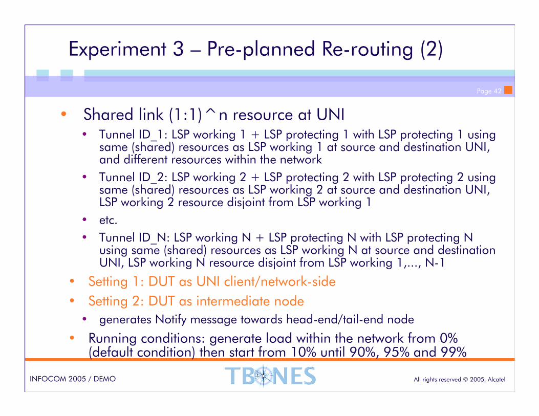
Experiment 3 – Pre-planned Re-routing (2)
• Shared link (1:1)^n resource at UNI• Tunnel ID_1: LSP working 1 + LSP protecting 1 with LSP protecting 1 using
same (shared) resources as LSP working 1 at source and destination UNI, and different resources within the network
• Tunnel ID_2: LSP working 2 + LSP protecting 2 with LSP protecting 2 using same (shared) resources as LSP working 2 at source and destination UNI, LSP working 2 resource disjoint from LSP working 1
• etc.
• Tunnel ID_N: LSP working N + LSP protecting N with LSP protecting N using same (shared) resources as LSP working N at source and destination UNI, LSP working N resource disjoint from LSP working 1,..., N-1
• Setting 1: DUT as UNI client/network-side
• Setting 2: DUT as intermediate node
• generates Notify message towards head-end/tail-end node
• Running conditions: generate load within the network from 0% (default condition) then start from 10% until 90%, 95% and 99%

Page 43
All rights reserved © 2005, AlcatelINFOCOM 2005 / DEMO
Prague-13
Oslo-9
Stockholm-11
Copenhagen-5
Amsterdam-12
Dublin-23
London-25
Brussels-7
Paris-8
Madrid-1
Zurich-17
Milan-50
(DUT)
Berlin-15
Athens-28
Budapest-2Vienna-14
Warsaw-27
Munich-21
Rome-6
Hamburg-18
Barcelona-16
Bordeaux-10
Lyon-19
Frankfurt-20
Glasgow-4
Belgrade-3
Strasbourg-22
Zagreb-26
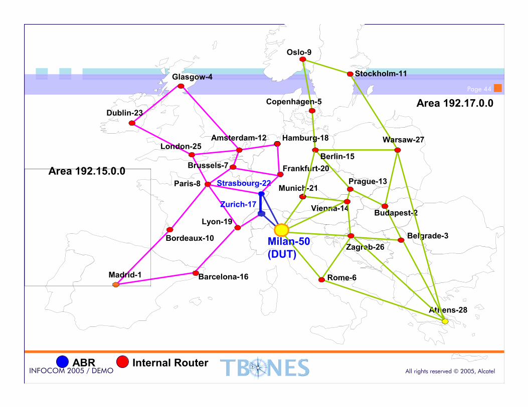
Area 192.15.0.0
Area 192.17.0.0
ABR Internal Router
Prague-13
Page 44
All rights reserved © 2005, AlcatelINFOCOM 2005 / DEMO
Prague-13
Oslo-9
Stockholm-11
Copenhagen-5
Amsterdam-12
Dublin-23
London-25
Brussels-7
Paris-8
Madrid-1
Zurich-17
Milan-50
(DUT)
Berlin-15
Athens-28
Budapest-2Vienna-14
Warsaw-27
Munich-21
Rome-6
Hamburg-18
Barcelona-16
Bordeaux-10
Lyon-19
Frankfurt-20
Glasgow-4
Belgrade-3
Strasbourg-22
Zagreb-26
Area 192.15.0.0
Area 192.17.0.0
ABR Internal Router
Prague-13
Page 45
All rights reserved © 2005, AlcatelINFOCOM 2005 / DEMO
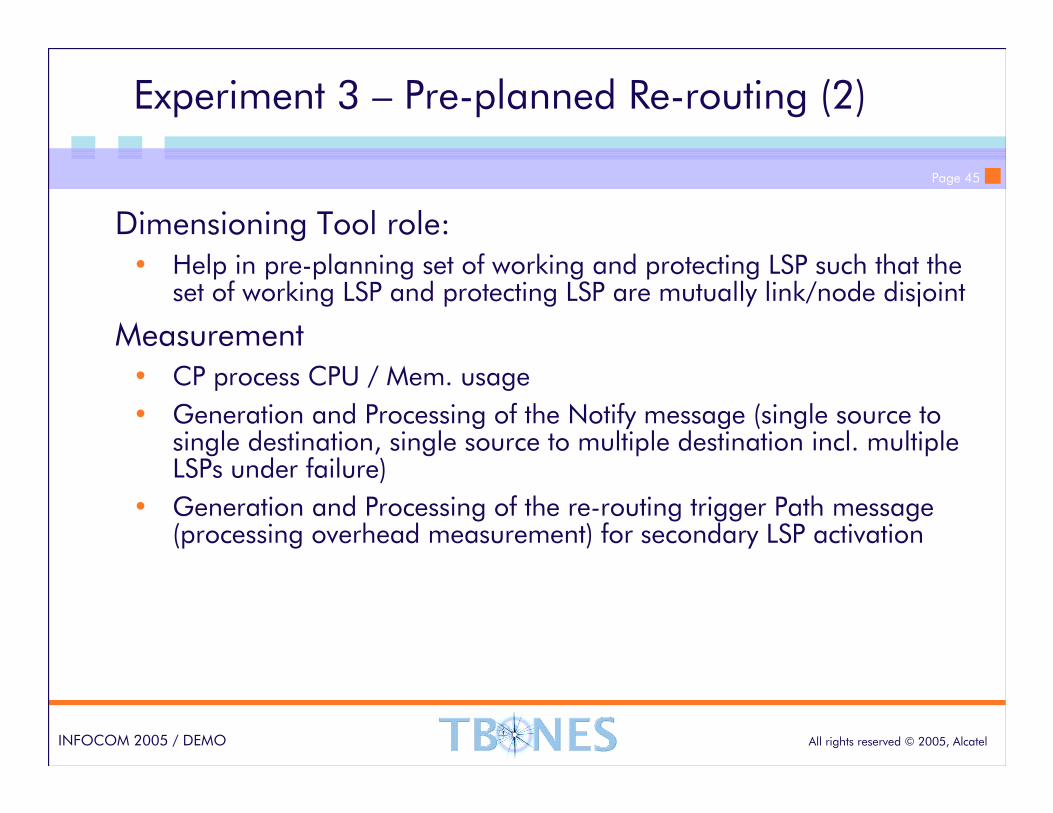
Experiment 3 – Pre-planned Re-routing (2)
Dimensioning Tool role:• Help in pre-planning set of working and protecting LSP such that the
set of working LSP and protecting LSP are mutually link/node disjoint
Measurement• CP process CPU / Mem. usage
• Generation and Processing of the Notify message (single source to single destination, single source to multiple destination incl. multiple LSPs under failure)
• Generation and Processing of the re-routing trigger Path message (processing overhead measurement) for secondary LSP activation
Page 46
All rights reserved © 2005, AlcatelINFOCOM 2005 / DEMO
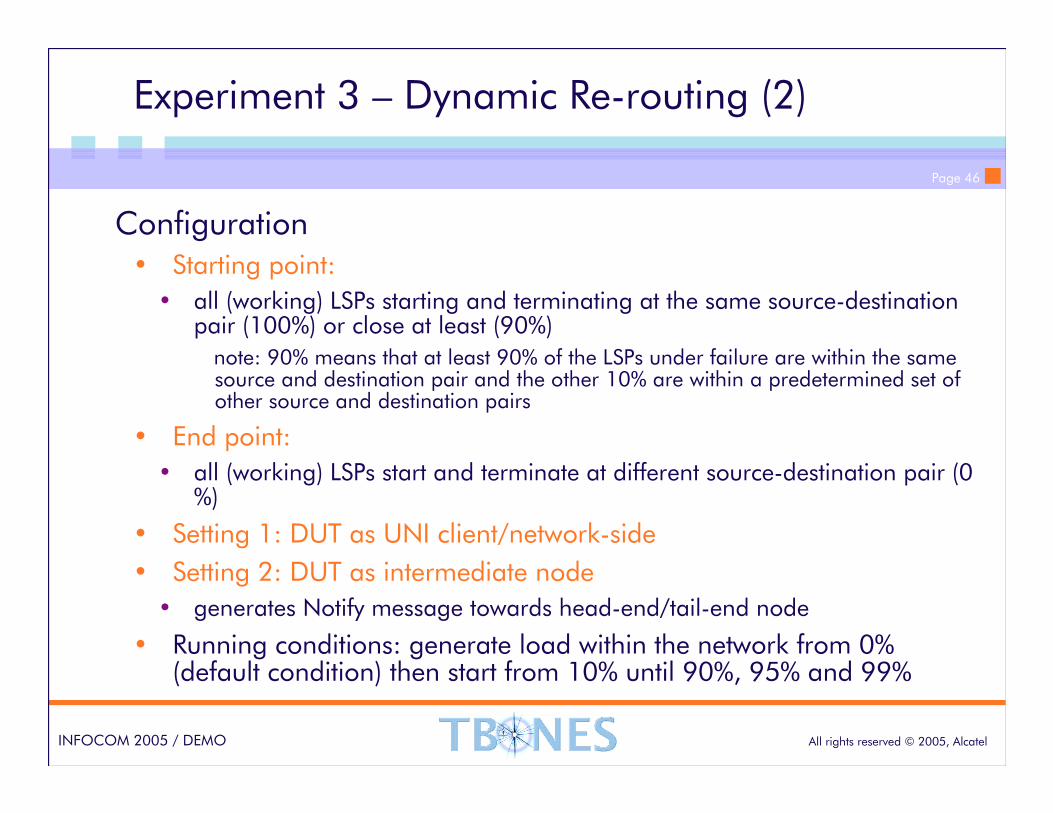
Experiment 3 – Dynamic Re-routing (2)
Configuration• Starting point:
• all (working) LSPs starting and terminating at the same source-destination pair (100%) or close at least (90%)
note: 90% means that at least 90% of the LSPs under failure are within the same source and destination pair and the other 10% are within a predetermined set of other source and destination pairs
• End point:
• all (working) LSPs start and terminate at different source-destination pair (0 %)
• Setting 1: DUT as UNI client/network-side
• Setting 2: DUT as intermediate node
• generates Notify message towards head-end/tail-end node
• Running conditions: generate load within the network from 0% (default condition) then start from 10% until 90%, 95% and 99%
Page 47
All rights reserved © 2005, AlcatelINFOCOM 2005 / DEMO
Experiment 3 – Dynamic Re-routing (2)
Measurement• CP process CPU / Mem. usage
• Generation and Processing of the Notify message (single source to single destination, single source to multiple destination incl. multiple LSPs under failure)
• Generation and Processing of the re-routing trigger Path message (processing overhead measurement) for primary LSP establishment
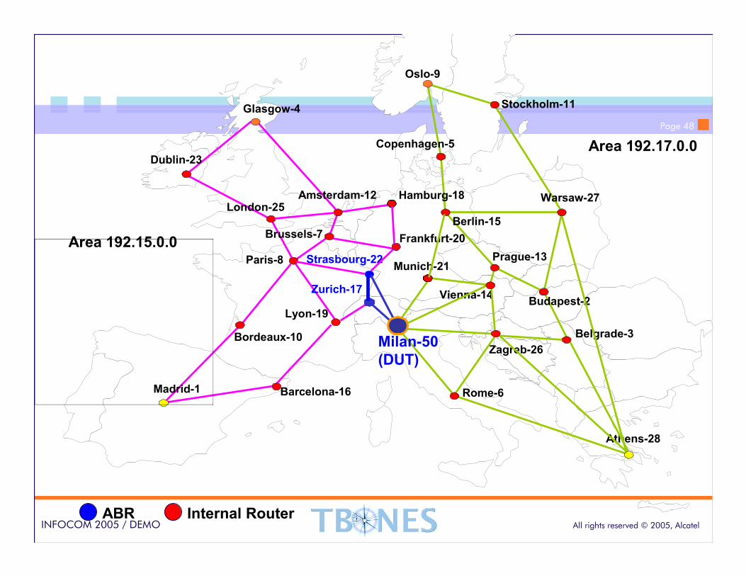
Page 48
All rights reserved © 2005, AlcatelINFOCOM 2005 / DEMO
Prague-13
Oslo-9
Stockholm-11
Copenhagen-5
Amsterdam-12
Dublin-23
London-25
Brussels-7
Paris-8
Madrid-1
Zurich-17
Milan-50
(DUT)
Berlin-15
Athens-28
Budapest-2Vienna-14
Warsaw-27
Munich-21
Rome-6
Hamburg-18
Barcelona-16
Bordeaux-10
Lyon-19
Frankfurt-20
Glasgow-4
Belgrade-3
Strasbourg-22
Zagreb-26
Area 192.15.0.0
Area 192.17.0.0
ABR Internal Router
Prague-13

Page 49
All rights reserved © 2005, AlcatelINFOCOM 2005 / DEMO
Prague-13
Oslo-9
Stockholm-11
Copenhagen-5
Amsterdam-12
Dublin-23
London-25
Brussels-7
Paris-8
Madrid-1
Zurich-17
Milan-50
(DUT)
Berlin-15
Athens-28
Budapest-2Vienna-14
Warsaw-27
Munich-21
Rome-6
Hamburg-18
Barcelona-16
Bordeaux-10
Lyon-19
Frankfurt-20
Glasgow-4
Belgrade-3
Strasbourg-22
Zagreb-26
Area 192.15.0.0
Area 192.17.0.0
ABR Internal Router
Prague-13

Page 50
All rights reserved © 2005, AlcatelINFOCOM 2005 / DEMO
Prague-13
Oslo-9
Stockholm-11
Copenhagen-5
Amsterdam-12
Dublin-23
London-25
Brussels-7
Paris-8
Madrid-1
Zurich-17
Milan-50
(DUT)
Berlin-15
Athens-28
Budapest-2Vienna-14
Warsaw-27
Munich-21
Rome-6
Hamburg-18
Barcelona-16
Bordeaux-10
Lyon-19
Frankfurt-20
Glasgow-4
Belgrade-3
Strasbourg-22
Zagreb-26
Area 192.15.0.0
Area 192.17.0.0
ABR Internal Router
Prague-13

Page 51
All rights reserved © 2005, AlcatelINFOCOM 2005 / DEMO
www.alcatel.com