Embed Size (px)
DESCRIPTION
American National Standard for Transformers
Citation preview
ANSI C57.12.55-1987(R1998)
American National Standard for Transformers - Used in Unit Installations, Including Unit Su bstations-Conformance Standard
Approved 4/7/86
American National Standards Institute, Inc.
The Institute of Electrical and Electronics Engineers, Inc 3 Park Avenue, NewYork, NY 10016-5997, USA
Copyright O 1987 by the Institute of Electrical and Electronics Engineers, Inc. All rights reserved. Printed in the United States of America.
Print: ISBN 0-7381-3649-2 SH95121 PDF: ISBN 0-7381-3650-6 SS95121
No part of this publication may be reproduced in any form, in an electronic retrieval system or otherwise, without the prior written permission of the publisher.
Copyright The Institute of Electrical and Electronics Engineers, Inc. Provided by IHS under license with IEEE Licensee=Fluor Corp no FPPPV per administrator /2110503106, User=chavez, franci
Not for Resale, 06/20/2012 09:23:11 MDTNo reproduction or networking permitted without license from IHS
--`,`````,``,,`,,`,,,,,,,`,`,,,-`-`,,`,,`,`,,`---
American National Standard
Approval of an American National Standard requires verification by ANSI that the requirements for due process, consensus, and other criteria for approval have been met by National the standards developer.
Consensus is established when, in the judgment of the ANSI Board of Standards Review, substantial agreement has been reached by directly and materially affected interests. Substantial agreement means much more than a simple majority, but not necessarily unanimity. Consensus requires that all views and objections be considered, and that a concerted effort be made toward their resolution.
The use of American National Standards is completely voluntary; their existence does not in any respect preclude anyone, whether he has approved the standards or not, from manufacturing, marketing, purchasing, or using products, processes, or procedures not conforming to the standards.
The American National Standards Institute does not develop standards and will in no circumstances give an interpretation of any American National Standard. Moreover, no person shall have the right or authority to issue an interpretation of an American National Standard in the name of the American National Standards Institute. Requests for interpretations should be addressed to the secretariat or sponsor whose name appears on the title page of this standard.
CAUTION NOTICE: This American National Standard may be revised or withdrawn at any time. The procedures of the American National Standards Institute require that action be taken to reaf f i i , revise, or withdraw this standard no later than five years from the date of approval. Purchasers of American National Standards may receive current information on all standards by calling or writing the American National Standards Institute.
11 Copyright The Institute of Electrical and Electronics Engineers, Inc. Provided by IHS under license with IEEE Licensee=Fluor Corp no FPPPV per administrator /2110503106, User=chavez, franci
Not for Resale, 06/20/2012 09:23:11 MDTNo reproduction or networking permitted without license from IHS
--`,`````,``,,`,,`,,,,,,,`,`,,,-`-`,,`,,`,`,,`---
Foreword
(This Foreword is not part of Amencan National Standard C57.12.55-1987.)
The High Voltage Apparatus Coordinating Committee (HVACC) was established July 24, 1972 by the Electrical and Electronic Technical Advisory Board (now superseded by the Electrical and Electronic Standards Management Board) of the American National Standards Institute. The responsibility assigned to HVACC was to review and evaluate existing American National Standards and other related standards for the purpose of developing a “Draft Standard” for unit substations and to develop recommendations for (1) correlating requirements of these standards and (2) adding requirements to these standards appropriate for product evaluation.
This standard results from the evaluation of existing American National Standards and the need to add requirements to these standards for the evaluation and conformance certification of dry-type transformers. This document refers to the proposed revision of American National Standard for Dry-Type Transformers, ANSUIEEE C57.12.01-1979 (now in preparation).
This document includes Appendixes A and B, outlining procedures recommended for qualiSling insulation systems; related material is covered in American National Standard Test for Thermal Evaluation of Insulation Systems for Ventilated Dry-Type Power and Distribution Transformers, ANSVIEEE C57.12.56-1984.
This standard is not intended to cover application, installation, or operation of dry-type transformers.
Transformers certified under this standard may contain accessories necessary for installation. For the conformance requirements for such accessories, reference should be made to the American National Standard for each specific accessory involved. Typical accessories of a pad-mounted installation are fuses, lightning arresters, circuit breakers, motor starter controls, and the like.
Suggestions for improvement of this standard will be welcome. They should be sent to the National Electrical Manufacturers Association, 2101 L Street, NW, Suite 300, Washington, DC 20037.
This standard was processed and approved for submittal to ANSI by the Accredited Standards Committee on Transformers, Regulators, and Reactors, C57. Committee approval of the standard does not necessarily imply that all committee members voted for its approval. At the time it approved this standard, the C57 Committee had the following members:
I. H. Koponen, Chair C. R. Willmore, Secretary
Organization Represented.. ....................................................................................................... ..Name of Representative
Electric Light and Power (EL&P) R. R. Bast I. O. Berkhan I. H. Koponen P. H. Philippidis B. F. Smith E. A. Villasuso J. P. Markey (Alt) S. Bennon W. P. Burt J. C. Dutton L. W. Long D. E. Massey D.C. Johnson (Alt)
National Electrical Manufacturers Association (NEMA) ........................................................... L. C. Aicher W. R. Courtade J. D. Douglass W. C. Kendall
Institute of Electrical and Electronics Engineers
... 111
Copyright The Institute of Electrical and Electronics Engineers, Inc. Provided by IHS under license with IEEE Licensee=Fluor Corp no FPPPV per administrator /2110503106, User=chavez, franci
Not for Resale, 06/20/2012 09:23:11 MDTNo reproduction or networking permitted without license from IHS
--`,`````,``,,`,,`,,,,,,,`,`,,,-`-`,,`,,`,`,,`---
H. D. Lewis W. J. McNutt R. L. Schwab R. E. Uptegraff, Jr G. C. Wilburn G. W. Maya11 (Alt) N. M. Neagle (Alt)
R. W. Seelbach
G. W. Iliff L. W. Johnson R. H. Richardson L. R. Smith
Underwriters Laboratories, Inc .................................................................................................. E. J. Huber
Individual Members .................................................................................................................... J. C. Arnold . .
Subcommittee HVACC on High Voltage Transformers, which developed this standard, had the following members:
R. B. Shores, Chair R. G. Hansen, Secretary
R. Bancroft G. M. Bell A. Bimbiris H. W. Book G. Bowers F. J. Brutt R. D. Buckley J. Budovec R. L. Capra C. E. Derbyshire
D. A. Duckett H. Gabel, Jr J. Hupp J. H. Keeler A. D. Kline G. Lusk M. L. Manning R. C. Mayer N. J. Melton
J. Nay R. Naysmith N. M. Neagle T. Orbeck D. Rose T. Rouse R. W. Seelbach R. Stranger R. E. Uptegraff, Jr A. C. Wurdak
The working group of the HVACC Subcommittee on High Voltage Transformers, which developed the major portion of this standard, had the following members:
A. D. Kline, Chair C. H. White, Secretary
C. E. Derbyshire N. El-SoXOgy
E. J. Huber N. J. Melton J. Nay
C. M. Pandza J. Sisson
iv Copyright The Institute of Electrical and Electronics Engineers, Inc. Provided by IHS under license with IEEE Licensee=Fluor Corp no FPPPV per administrator /2110503106, User=chavez, franci
Not for Resale, 06/20/2012 09:23:11 MDTNo reproduction or networking permitted without license from IHS
--`,`````,``,,`,,`,,,,,,,`,`,,,-`-`,,`,,`,`,,`---
CLAUSE
1.
2.
3.
4.
5.
6.
7.
8.
9.
10.
Scope and Purpose .............................................................................................................................................. 1
1.2 Exceptions .......................................................................... ..................................... 1
Referenced Standards.. ............................................................... ...................................... 2
2.1 American National Standards ........ ........................................................................ 2 .. 2 2.2 Other Standards .......................................................................
Transformer Requirements ........................................................................ ... 2
1.1 Scope .......................................................................................................................................................... 1
........................................................................ ... 2
.. 2
Enclosures
4.1 Definition ....................................................................... 4.2 Categories ....................................... ........................................................................ 2
Enclosures ~ Basic Requirements ................................................................................................................... ..4
5.1 Construction ............................................................................................................................................... 4
5.3 Enclosure Security ............................................................. ................................... 12 5.2 Construction Tests .............................................................. ................................... 10
Outdoor Enclosures ~ Requirements ............................................................................................................... 16
6.2 Enclosure Types and Design Tests ...................................................................... 17
Outdoor Enclosures ~ Design Tests .....
7.1 Spray Test ...................................... ....................................................................... 20 7.2 Dust Tests 21 7.3 External-Icing (Sleet) Test ............. ...................................................................... 21 7.4 Hosedown Test ...................................................................................................... 22 7.5 Corrosion-Resistance Test .............. ...................................................................... 22
Enclosures ~ Marking .......................................................................................................... .24
Conformance Tests .......................................................................................................... .24
9.1 Definition .... .......................................................................................................... 24 9.2 Requirements ..................................................................... ................................... 24
Certification Guidelines ......................... ...................................................................... .26
10.1 Sampling ........................................ ...................................................................... 26
6.1 Construction ....................................................................... 16
........................................................................ 20
..............................................................................................................
10.2 Treatment of Test Failures .................................................................................... 10.3 Audit Procedure ............................. 10.4 Design or Material Modifications .........................................................................
26 ...................................................................... 26
26
Annex A (informative) Test of Minor Variations of Component Materials in Insulation Systems ............................ .27
Annex B (informative) Test of Substitute Varnishes in Insulation Systems ................................................................ 30
V
Copyright The Institute of Electrical and Electronics Engineers, Inc. Provided by IHS under license with IEEE Licensee=Fluor Corp no FPPPV per administrator /2110503106, User=chavez, franci
Not for Resale, 06/20/2012 09:23:11 MDTNo reproduction or networking permitted without license from IHS
--`,`````,``,,`,,`,,,,,,,`,`,,,-`-`,,`,,`,`,,`---
American National Standard for Transformers -
Dry-Type Transformers Used in Unit Installations, Including Unit Substations - Conformance Standard
1. Scope and Purpose
1.1 Scope
This standard describes certain electrical, mechanical, and safety requirements and conformance tests for dry-type distribution and power transformers and for autotransformers. These transformers may be either single-phase or polyphase, with ventilated, nonventilated, or scaled enclosures.
Such transformers may be remotely or integrally associated with primary or secondary switchgear or substations, or both. The range of transformers is 601 volts through 34 500 volts (either primary or secondary) in sizes of 1 kVA through 2 500 kVA. Such transformers are intended to be installed in accordance with the AmericanNational Standard National Electrical Code (ANSI/NFPA 70- 1987). All manufacturers seeking certification under this standard should demonstrate that performance requirements have been met by perfoming the tests herein, by submitting data from earlier tests, by exhibiting proof of satisfactory field service, or by an appropriate combination of these methods. Families of insulation systems may be certified on the basis of tests performed on one representative model.
1.2 Exceptions
This standard applies to all dry type transformers except the following:
Instrument transformers Step-voltage and induction voltage regulators Current regulators Arc fumace transformers Rectifier transformers Specialty transformers Mine transformers Motor starting reactors and transformers Transformers utilizing insulation systems other than conventional varnish impregnated systems
This standard excludes transformers under the exclusive control of electrical utilities and used for communication, metering, generation, control, transformation, transmission, and distribution of electric energy regardless of whether such transformers are located indoors in buildings and rooms used exclusively by utilities for such purposes, or outdoors on property owned or leased, established rights on private property, or on public rights of way (highways, streets, roads, and the like).
Copyright O 1987 IEEE All Rights Reserved 1
Copyright The Institute of Electrical and Electronics Engineers, Inc. Provided by IHS under license with IEEE Licensee=Fluor Corp no FPPPV per administrator /2110503106, User=chavez, franci
Not for Resale, 06/20/2012 09:23:11 MDTNo reproduction or networking permitted without license from IHS
--`,`````,``,,`,,`,,,,,,,`,`,,,-`-`,,`,,`,`,,`---
AMERICAN NATIONAL STANDARD C57.12.55-1987
2. Referenced Standards
2.1 American National Standards
This standard is intended to be used in conjunction with the following American National Standards. When these standards are superseded by a revision approved by the American National Standards Institute, Inc, the revision shall apply.
ANSI C57.12.70-1978, Terminal Markings and Connections for Distribution and Power Transformers
ANSUIEEE C57.12.0 1 - 1979, General Requirements for Dry-Type Distribution and Power Transformers
ANSUIEEE C57.12.56-1984, Test for Thermal Evaluation of Insulation Systems for Ventilated Dry-Type Power and Distribution Transformers
ANSUIEEE C57.12.80-1978 (R1986), Terminology for Power and Distribution Transformers
ANSUIEEE C57.12.91-1979, Test Code for Dry-Type Distribution and Power Transformers
ANSUIEEE 99-1980, Preparation of Test Procedures for the Thermal Evaluation of Insulation Systems for Electric Equipment
ANSUIEEE 100-1984 Dictionary of Electrical and Electronics Terms
ANSUNEMA MG2-1977, Safety Standard for Construction and Guide for Selection, Installation, and Use of Electric Motors and Generators
ANSI/NFPA 70-1987, National Electrical Code
ANSI/UL 347- 1985, High Voltage Industrial Control Equipment
2.2 Other Standards
This standard is also intended to be used in conjunction with the following publications:
NEMA TR 1-1980, Transformers, Regulators, and Reactors
MIL-STD-209C-1968, Swinging Eyes and Attachments for Lifting and Tying Down Military Equipment
3. Transformer Requirements
The requirements for dry-type transformers that are used in unit substations or that are pad mounted shall be in accordance with ANSUIEEE C57.12.01-1979 and ANSUIEEE C57.12.91-1979.
The recommended procedure for thermal evaluation of the insulation system is covered by ANSUIEEE C57.12.56- 1984 and Appendixes A and B of this standard.
4. Enclosures
4.1 Definition
An enclosure is a surrounding case or housing used to provide a degree of protection to conductors or equipment and to provide a degree of protection to persons against contacting live parts.
4.2 Categories
The categories of indoor and outdoor enclosures shall be as follows:
4.2.1 Category “A” Indoor or Outdoor Enclosures: Category “A” indoor or outdoor enclosures are intended (1) for ground level use in installations subject to deliberate, unauthorized acts by members of the unsupervised general
2 Copyright O 1987 IEEE All Rights Reserved
Copyright The Institute of Electrical and Electronics Engineers, Inc. Provided by IHS under license with IEEE Licensee=Fluor Corp no FPPPV per administrator /2110503106, User=chavez, franci
Not for Resale, 06/20/2012 09:23:11 MDTNo reproduction or networking permitted without license from IHS
--`,`````,``,,`,,`,,,,,,,`,`,,,-`-`,,`,,`,`,,`---

AMERICAN NATIONAL STANDARD C57.12.55-1987
public and (2) primarily to provide a degree of protection against contact with the enclosed equipment. These enclosures shall meet the requirements given for Category A enclosures in Table 1.
4.2.2 Category “B” Indoor or Outdoor Enclosures: Category “B” indoor or outdoor enclosures are intended (1) for use in installations not subject to deliberate, unauthorized acts by members of the unsupervised general public and (2) primarily to provide a degree of protection to unauthorized and untrained personnel against incidental contact with the enclosed equipment. These enclosures shall meet the requirements given for Category B enclosures in Table 1.
4.2.3 Category “C” Indoor or Outdoor Enclosures: Category “C” indoor or outdoor enclosures are intended (1) for use in installations in secured areas generally inaccessible to unauthorized and untrained persons and (2) to provide a degree of protection against contact with the enclosed equipment. These enclosures shall meet the requirements given for Category C enclosures in Table 1.
4.2.4 Sealed Enclosures: Sealed enclosures shall be in accordance with ANSI C57.12.01-1979.
Table 1- Requirements for Category A, B, and C Enclosures Required for Categories
Feature Reference Sections A B C All Enclosures
Enclosure security Basic enclosures requirements
Rigidity (sheet metal) Exposed live parts permissible Operating handles
Operating handles - height
Vent openings - “line of sight” restriction
Doors (if supplied) Doors - handles lockable Doors - captive fasteners Hinge pins - no removable door Lifting provisions Gages, valves, etc - locked cover Guards for exposed fan blades Caution and warning signs
Outdoor Enclosures Matenal Hinges Gaskets Doorstop Types and design tests
Tests Spray test Dust test
External-icing (sleet) test Hosedown Corrosion resistance
5.3 5 5.1.1; 5.2.3 5.1.9 5.1.16
5.1.16
5.1.10; 5.1.11
5.1.4 5.1.4 5.1.4 5.1.4 5.1.2 5.1.18 5.1.19 8
6.1 6.1 6.1 6.1 6.2
7.1 7.2
7.3 7.4 7.5
Yes Yes Yes No
Locked Cover
78 inches Maximum
Not Applicable
Yes Yes
Not Applicable Yes Yes Yes
Not Applicable Yes
Yes Yes Yes Yes Yes
All Types Types 103, 103S, 104 All Types Type 104
Types 103, 103S.1 04
Not Applicable Yes Yes No No
Requirements 78 inches Maximum
Yes
Yes Yes* Yes* No Yes No Yes Yes
Yes Yes Yes Yes Yes
All Types Types 103, 103S, 104 All Types Type 104
Types 103, 103S.1 04
Not Applicable Yes
Not Applicable Yes No
Requirements 78 inches Maximum
No
Yes No No No Yes No
Not Applicable Yes
Yes Yes Yes Yes Yes
All Types Types 103, 103S, 104 A11Types Type 104
Types 103, 103S.1 04
*Either lockable handles or captive fasteners, but not both, are required
Copyright O 1987 IEEE All Rights Reserved 3
Copyright The Institute of Electrical and Electronics Engineers, Inc. Provided by IHS under license with IEEE Licensee=Fluor Corp no FPPPV per administrator /2110503106, User=chavez, franci
Not for Resale, 06/20/2012 09:23:11 MDTNo reproduction or networking permitted without license from IHS
--`,`````,``,,`,,`,,,,,,,`,`,,,-`-`,,`,,`,`,,`---
AMERICAN NATIONAL STANDARD C57.12.55-1987
5. Enclosures - Basic Requirements
5.1 Construction
5.1 .I General
If of metal, enclosures shall be suitably supported, constructed, and assembled so that they will have the strength and rigidity necessary to resist the abuses to which they are likely to be subjected, without total or partial collapse that may result in an increased fiie hazard due to reduction of spacings, loosening or displacement of parts, or other serious defects. Nonmetallic materials may be used as all or part of an enclosure if found suitable for the application and shall otherwise comply with 5.1.1. Among the factors to be taken into consideration when a nonmetallic material is being judged for acceptability are the following: (1) physical strength, (2) resistance to impact, (3) moisture-absorptive properties, (4) combustibility, (5) ground plane between high voltage and enclosure, and (6) resistance to distortion at temperatures to which it may be subjected under conditions of normal and abnormal use. These factors are considered with respect to thermal aging. The enclosure shall be capable of withstanding the tests specified in this standard that are applicable to the location and environmental conditions to which it will be exposed.
5.1.2 Lifting Provisions
Lifting provisions shall provide a distributed balanced lift in a vertical direction for the assembled transformer and shall be designed to provide a safety factor of five or more. The safety factor of five is the ratio of the ultimate stress of material used to the working stress.' The working stress is the maximum combined stress developed in the lifting provisions by the static lead of the completely assembled transformer.2
A spreader bar may be required to lift the complete unit.
If lifted from the core and coil by removing the top cover, the maximum angle of lift (measured from vertical) shall be 30 degrees.
5.1.3 Protection of Inside and Outside Surfaces
Unless the enclosure is of a material that will resist corrosion, both inside and outside surfaces shall be suitably protected by painting, galvanizing, plating, or other equivalent means.
5.1.4 Covers and Doors
If an enclosure cover is not of the drawout construction type but gives access to fuses or any other overload-protective devices the normal functioning of which requiresrenewal, or if it is necessary to open the cover in connection with the normal operation of the device, the cover shall be hinged.
Exception: Fuses for instrument transformers, internal fans, and the like may be behind bolted covers.
A part of the enclosure such as a door, cover, or panel giving access to the inside of the enclosure shall be provided with fasteners for firmly securing it in place. Such fasteners shall be so located or used in multiple so as to hold the door or cover closed over its entire length. A hinged cover more than 48 inches (1219 millimeters) long on the hinged side shall have at least a two-point latch operated by a single knob or handle or shall have at least two captive fasteners.
'Taken from American National Standard Safety Standard for Constniction and Guide for Selection, Installation, and Use of Electric Motors and Generators, ANSI/NEMA MG2- 1977, paragraph MC 2-2-03, Lifting Means 2Taken from Specification MIL-STD-209C, Swinging Eyes and Attachments for Lifting and Tying Down Military Equipment, August I, 1968 MIL publications are available from the Navy Publications and Forms Center, 5801 Tabor Avenue, Philadelphia, PA 19120
4 Copyright O 1987 IEEE All Rights Reserved
Copyright The Institute of Electrical and Electronics Engineers, Inc. Provided by IHS under license with IEEE Licensee=Fluor Corp no FPPPV per administrator /2110503106, User=chavez, franci
Not for Resale, 06/20/2012 09:23:11 MDTNo reproduction or networking permitted without license from IHS
--`,`````,``,,`,,`,,,,,,,`,`,,,-`-`,,`,,`,`,,`---
AMERICAN NATIONAL STANDARD C57.12.55-1987
The opening handles for doors in Category A and B enclosures shall be lockable. However, captive fasteners are permitted on Category B enclosures. Exposed hinge pins shall be nonremovable on doors of Category A enclosures or, as an alternative, the door shall be nonremovable in the closed position.
A door or cover shall shut closely against a 1/4-inch (6.4-millimeter) rabbet (as shown in Figure 1) or the equivalent, or shall have a minimum overlap of 1/2 inch, or shall have flanges for the full length of the four edges. Flanges on a door or cover shall fit closely with the outside walls of the enclosure proper and shall not be less than 7/16 inch (11.1 millimeters) in depth. A suitable combination of flange and rabbet is acceptable. Figure 2 illustrates typical constructions that are considered to comply with this requirement. Other constructions may be suitable.
Cover plates intended to be removed for inspection and maintenance of energized parts and wiring shall not exceed 12 square feet (1.1 1 square meters) in area or 60 pounds (27.2 kilograms) in weight unless they are equipped with lifting means or hinges.
(6.4 mm)
Figure 1 -Rabbet
I r s LEOEND:
f-1 CABINET
I l u DOOR OR - COVER 1 3
INCHES I f I l I6 I i I MILLIMETERS I 3 2 I 4 8 I 12 7 I 19 I
Figure 2 -Typical Constructions
5.1.5 Cast-Metal Enclosures
An enclosure of cast metal shall be at least 1/8 inch (3.2 millimeters) thick at every point, greater than 1/8 inch (3.2 millimeters) thick at reinforcing ribs and door edges, and not less than 1/4 inch (6.4 millimeters) thick at tapped holes for conduit.
Exception: At other than plain or threaded conduit holes, die-cast metal shall be:
Copyright O 1987 IEEE All Rights Reserved 5
Copyright The Institute of Electrical and Electronics Engineers, Inc. Provided by IHS under license with IEEE Licensee=Fluor Corp no FPPPV per administrator /2110503106, User=chavez, franci
Not for Resale, 06/20/2012 09:23:11 MDTNo reproduction or networking permitted without license from IHS
--`,`````,``,,`,,`,,,,,,,`,`,,,-`-`,,`,,`,`,,`---
AMERICAN NATIONAL STANDARD C57.12.55-1987
1)
2)
Not less than 3/32 inch (2.4 millimeters) thick for an area greater than 24 square inches (0.015 square meters) or having any dimensions greater than 6 inches (152 millimeters). Not less than 1/16 inch (1.6 millimeters) thick for an area of 24 square inches (0.015 square meters) or less and having no dimensions greater than 6 inches (152 millimeters). The area limitation may be obtained by the provision of suitable reinforcing ribs subdividing a larger area.
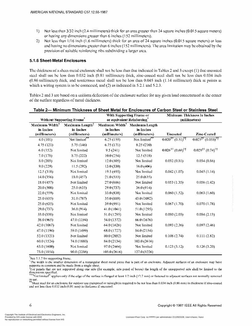
5.1.6 Sheet-Metal Enclosures
The thickness of a sheet-metal enclosure shall not be less than that indicated in Tables 2 and 3 except (1) that uncoated steel shall not be less than 0.032 inch (0.81 millimeter) thick, zinc-coated steel shall not be less than 0.034 inch (0.86 millimeter) thick, and nonferrous metal shall not be less than 0.045 inch (1.14 millimeter) thick at points at which a wiring system is to be connected, and (2) as indicated in 5.2.1 and 5.2.3.
Tables 2 and 3 are based on a uniform deflection of the enclosure surface for any given load concentrated at the center of the surface regardless of metal thickness.
Table 2- Minimum Thickness of Sheet Metal for Enclosures of Carbon Steel or Stainless Steel With Supporting Frame or Minimum Thickness in Inches
Without Supporting Frame* or equivalent Reinforcing* (millimeters) Maximum Width? Maximum Length$ Maximum Width? Maximum Length
in Inches in Inches in Inches in Inches
4.0 (101) Not limited** 6.25 (159) Not limited** 0.020tt (0.51)tt 0.023tt (0.058)tt
(millimeters) (millimeters) (millimeters) (millimeters) Uncoated Zinc-Coated
4.75 (121)
6.0 (152)
7.0 (178)
8.0 (203)
9.0 (229)
12.5 (318)
14.0 (356)
18.0 (457)
22.0 (559)
20.0 (508)
25.0 (635)
25.0 (635)
29.0 (737)
33.0 (838)
38.0 (965)
42.0 (1067)
47.0 (1194)
52.0 (1321)
60.0 (1524)
63.0 (1600)
73.0 (1854)
5.75 (146)
Not limited 8.75 (222)
Not limited 11.5 (292)
Not limited 18.0 (457)
Not limited 25.0 (635)
Not limited 3 1 .O (787)
Not limited 36.0 (914)
Not limited 47.0 (1194)
Not limited 59.0 (1499)
Not limited 74.0 (1880)
Not limited 90.0 (2286)
6.75 (171)
9.5 (241)
10.0 (254)
12.0 (305)
13.0 (330)
19.5 (495)
21.0 (533)
27.0 (686)
29.0 (737)
33.0 (838)
35.0 (889)
39.0 (991)
41.0 (1041)
51.0 (1295)
54.0 (1372)
64.0 (1626)
68.0 (1727)
80.0 (2032)
84.0 (2134)
97.0 (2464)
103 .O (26 16)
8.25 (210)
Not limited 12.5 (318)
Not limited 16.0 (406)
Not limited 25.0 (635)
Not limited 36.0 (914)
Not limited 43 .O (1 092)
Not limited 51.0 (1295)
Not limited 66.0 (1676)
Not limited 84.0 (2134)
Not limited 103.0 (2616)
Not limited 127.0 (3226)
0.026tt (0.66)ti
0.032 (0.81)
0.042 (1.07)
0.053 (1.35)
0.060 (1.52)
0.067 (1.70)
0.080 (2.03)
0.093 (2.36)
0.108 (2.74)
0.123 (3.12)
O. 02 9 t t (O .74)ti
0.034 (0.86)
0.045 (1.14)
0.056 (1.42)
0.063 (1.60)
0.070 (1.78)
0.084 (2.13)
0.097 (2.46)
0.1 11 (2.82)
0.126 (3.20)
*See 5.1.7 for supporting frame. ?The width is the smaller dimension of a rectangular sheet metal piece that is part of an enclosure. Adjacent surfaces of an enclosure may have supports in common and be made from a single sheet. TFor panels that are not supported along one side (for example, side panel of boxes) the length of the unsupported side shall be limited to the dimensions specified.
’Not limited” applies only if the edge of the surface is flanged at least 1/2 inch (12.7 mm) or fastened to adjacent surfaces not normally removed in use. ??Sheet steel for an enclosure for outdoor use (rainproof or raintight)is required to be not less than 0.034 inch (0.86 mm) in thickness if zine-coated and not less than 0.032 inch (0.81 mm) in thickness if uncoated.
**,
6 Copyright O 1987 IEEE All Rights Reserved
Copyright The Institute of Electrical and Electronics Engineers, Inc. Provided by IHS under license with IEEE Licensee=Fluor Corp no FPPPV per administrator /2110503106, User=chavez, franci
Not for Resale, 06/20/2012 09:23:11 MDTNo reproduction or networking permitted without license from IHS
--`,`````,``,,`,,`,,,,,,,`,`,,,-`-`,,`,,`,`,,`---
AMERICAN NATIONAL STANDARD C57.12.55-1987
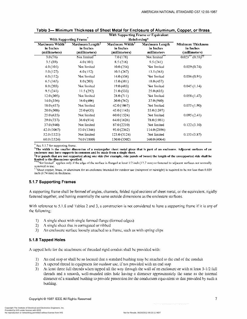
Table 3- Minimum Thickness of Sheet Metal for Enclosure of Aluminum, Copper, or Brass With Supporting Frame or Equivalent
With Supporting Frame* Reinforcing" Maximum WidthT Maximum LengthT Maximum WidthT Maximum Length Minimum Thickness
in Inches in Inches in Inches in Inches in Inches (millimeters) (millimeters) (millimeters) millimeters (millimeters)
3.0 (76) Not limited" 7.0 (178) Not limited" 0.023TT (0.58)TT 3.5 (89) 4.0 (101) 8.5 (216) 9.5 (241)
4.0 (101) Not limited 10.0 (254) Not limited 0.029 (0.74) 5.0 (127) 6.0(152) 10.5 (267) 13.5 (343) 6.0 (152) Not limited 14.0 (356) Not limited 0.036 (0.91)
8.0 (203) Not limited 19.0 (483) Not limited 0.045 (1.14) 9.5 (241) 11.5 (292) 21.0 (533) 25.0 (635) 12.0 (305) Not limited 28.0 (71 1) Not limited 0.058 (1.47) 14.0 (356) 16.0 (406) 30.0 (762) 37.0 (940) 18.0 (457) Not limited 42.0 (1067) Not limited 0.075 (1.90) 20.0 (508) 25.0 (635) 45.0 (1 143) 55.0 (1397) 25.0 (635) Not limited 60.0 (1 524) Not limited 0.095 (2.41) 29.0 (737) 36.0 (914) 64.0 (1626) 78.0 (1981) 37.0 (940) Not limited 87.0 (2210) Not limited 0.122 (3.10)
42.0 (1067) 53.0 (1346) 93.0 (2362) 114.0 (2896) 52.0 (1321) Not limited 123.0 (3124) Not limited 0.153 (3.87) 60.0 (1524) 74.0 (1880) 130.0 (3302) 160.0 (4064)
6.5 (165) 8.0 (203) 15.0 (381) 18.0 (457)
* See 5 . i .7 for supporting frame. +The width is the smaller dimension of a rectangular sheet metal piece that is part of an enclosure. Adjacent surfaces of an enclosure may have supports in common and be made from a single sheet. $For panels that are not supported along one side (for example, side panels of boxes) the length of the unsupported side shall be hited to the dimensions specified.
Not limited" applies only if the edge of the surface is flanged at least 1/2 inch (12.7 mm) or fastened to adjacent surfaces not normally removed in use. ++Sheet copper, brass, or aluminum for an enclosure intended for outdoor use (rainproof or raintight) is required to be not less than 0.029 inch (0.74 mm) in thickness.
5.1.7 Supporting Frames
A supporting frame shall be formed of angles, channels, folded rigid sections of sheet metal, or the equivalent, rigidly fastened together, and having essentially the same outside dimensions as the enclosure surfaces.
With reference to 5.1.8 and Tables 2 and 3, a construction is not considered to have a supporting frame if it is any of the following:
1) 2) 3)
A single sheet with single formed flange (formed edges) A single sheet that is corrugated or ribbed An enclosure surface loosely attached to a frame, such as with spring clips
5.1.8 Tapped Holes
A tapped hole for the attachment of threaded rigid conduit shall be provided with:
1) 2) 3)
An end stop or shall be so located that a standard bushing may be attached to the end of the conduit A tapered thread in equipment for outdoor use, if not provided with an end stop At least three full threads when tapped all the way through the wall of an enclosure or with at least 3-1/2 full threads and a smooth, well-rounded inlet hole having a diameter approximately the same as the internal diameter of a standard bushing to provide protection for the conductors equivalent to that provided by such a bushing.
Copyright O 1987 IEEE All Rights Reserved 7
Copyright The Institute of Electrical and Electronics Engineers, Inc. Provided by IHS under license with IEEE Licensee=Fluor Corp no FPPPV per administrator /2110503106, User=chavez, franci
Not for Resale, 06/20/2012 09:23:11 MDTNo reproduction or networking permitted without license from IHS
--`,`````,``,,`,,`,,,,,,,`,`,,,-`-`,,`,,`,`,,`---
AMERICAN NATIONAL STANDARD C57.12.55-1987
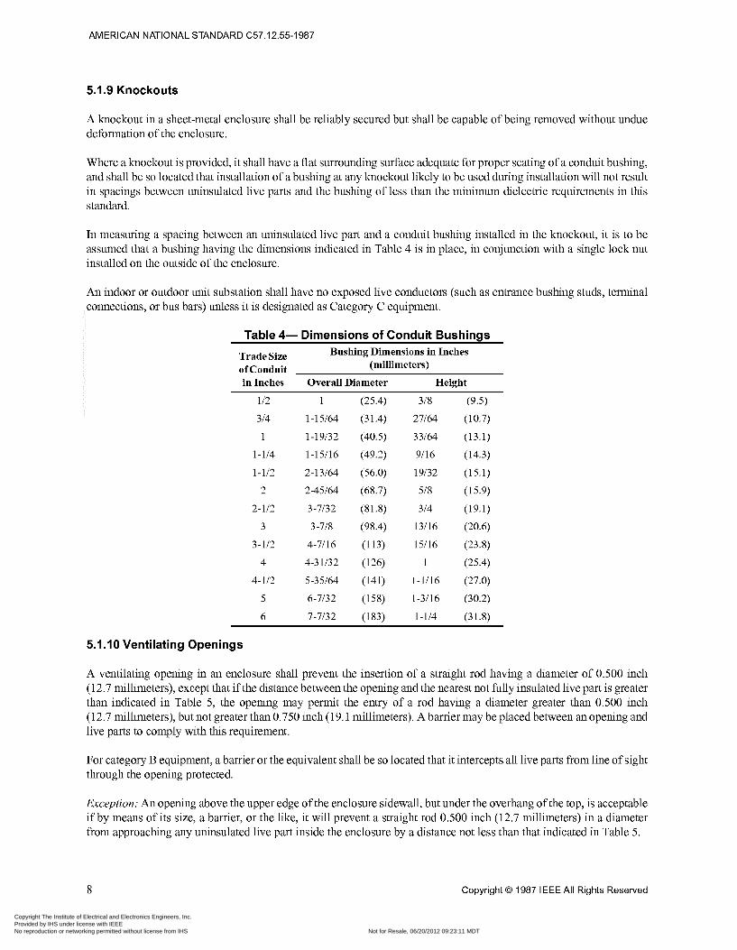
5.1.9 Knockouts
A knockout in a sheet-metal enclosure shall be reliably secured but shall be capable of being removed without undue deformation of the enclosure.
Where a knockout is provided, it shall have a flat surrounding surface adequate for proper seating of a conduit bushing, and shall be so located that installation of a bushing at any knockout likely to be used during installation will not result in spacings between uninsulated live parts and the bushing of less than the minimum dielectric requirements in this standard.
In measuring a spacing between an uninsulated live part and a conduit bushing installed in the knockout, it is to be assumed that a bushing having the dimensions indicated in Table 4 is in place, in conjunction with a single lock nut installed on the outside of the enclosure.
An indoor or outdoor unit substation shall have no exposed live conductors (such as entrance bushing studs, terminal connections, or bus bars) unless it is designated as Category C equipment.
Table 4- Dimensions of Conduit Bushings Bushing Dimensions in Inches
(millimeters) Trade Size of Conduit in Inches Overall Diameter Height
1 /2 1 (25.4) 3/8 (9.5) 3/4 1-15/64 (31.4) 27/64 (10.7)
1 1-19/32 (40.5) 33/64 (13.1)
1-1/4 1-15/16 (49.2) 9/16 (14.3)
1-1/2 2-13/64 (56.0) 19/32 (15.1)
2 2-45/64 (68.7) 5/8 (15.9)
2-1/2 3-7/32 (81.8) 3/4 (19.1)
3 3-7,’s (98.4) 13/16 (20.6)
3-1/2 4-7/16 (113) 15/16 (23.8)
4 4-31/32 (126) 1 (25.4)
4-1/2 5-35/64 (141) 1-1/16 (27.0)
5 6-7/32 (158) 1-3/16 (30.2)
6 7-7/32 (183) 1-1/4 (31.8)
5.1.10 Ventilating Openings
A ventilating opening in an enclosure shall prevent the insertion of a straight rod having a diameter of 0.500 inch (12.7 millimeters), except that if the distance between the opening and the nearest not fully insulated live part is greater than indicated in Table 5, the opening may permit the entry of a rod having a diameter greater than 0.500 inch (12.7 millimeters), but not greater than 0.750 inch (19.1 millimeters). A barrier may be placed between an opening and live parts to comply with this requirement.
For category B equipment, a barrier or the equivalent shall be so located that it intercepts all live parts from line of sight through the opening protected.
Exception: An opening above the upper edge of the enclosure sidewall, but under the overhang of the top, is acceptable if by means of its size, a barrier, or the like, it will prevent a straight rod 0.500 inch (12.7 millimeters) in a diameter from approaching any uninsulated live part inside the enclosure by a distance not less than that indicated in Table 5.
8 Copyright O 1987 IEEE All Rights Reserved
Copyright The Institute of Electrical and Electronics Engineers, Inc. Provided by IHS under license with IEEE Licensee=Fluor Corp no FPPPV per administrator /2110503106, User=chavez, franci
Not for Resale, 06/20/2012 09:23:11 MDTNo reproduction or networking permitted without license from IHS
--`,`````,``,,`,,`,,,,,,,`,`,,,-`-`,,`,,`,`,,`---
AMERICAN NATIONAL STANDARD C57.12.55-1987
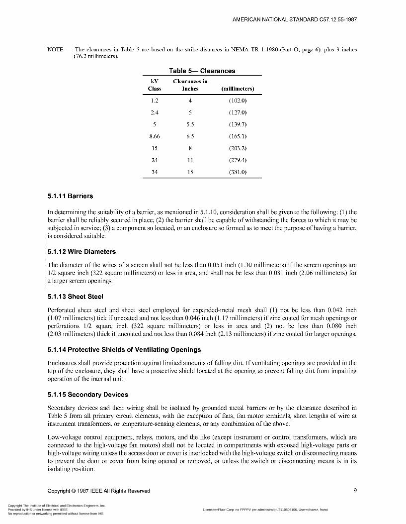
NOTE ~ The clearances in Table 5 are based on the strike distances in NEMA TR 1-1980 par i O, page 6), plus 3 inches (76.2 millimeters).
Table 5- Clearances kV Clearances in
Class Inches (millimeters)
1.2 4 (102.0)
2.4 5 (127.0)
5 5.5 (139.7)
8.66 6.5 (165.1)
15 8 (203.2)
24 11 (279.4)
34 15 (381.0)
5.1 .I 1 Barriers
In determining the suitability of a barrier, as mentioned in 5.1.10, consideration shall be given to the following: (1) the barrier shall be reliably secured in place; (2) the barrier shall be capable of withstanding the forces to which it may be subjected in service; (3) a component so located, or an enclosure so formed as to meet the purpose of having a barrier, is considered suitable.
5.1.12 Wire Diameters
The diameter of the wires of a screen shall not be less than 0.05 1 inch (1.30 millimeters) if the screen openings are 1/2 square inch (322 square millimeters) or less in area, and shall not be less than 0.081 inch (2.06 millimeters) for a larger screen openings.
5.1.13 Sheet Steel
Perforated sheet steel and sheet steel employed for expanded-metal mesh shall (1) not be less than 0.042 inch (1 .O7 millimeters) tick if uncoated and not less than 0.046 inch (1.17 millimeters) if zinc coated for mesh openings or perforations 1/2 square inch (322 square millimeters) or less in area and (2) not be less than 0.080 inch (2.03 millimeters) thick if uncoated and not less than 0.084 inch (2.13 millimeters) if zinc coated for larger openings.
5.1.14 Protective Shields of Ventilating Openings
Enclosures shall provide protection against limited amounts of falling dirt. If ventilating openings are provided in the top of the enclosure, they shall have a protective shield located at the opening to prevent falling dirt from impairing operation of the internal unit.
5.1 .I 5 Secondary Devices
Secondary devices and their wiring shall be isolated by grounded metal barriers or by the clearance described in Table 5 from all primary circuit elements, with the exception of fans, fan motor terminals, short lengths of wire at instrument transformers, or temperature-sensing elements, or any combination of the above.
Low-voltage control equipment, relays, motors, and the like (except instrument or control transformers, which are connected to the high-voltage fan motors) shall not be located in compartments with exposed high-voltage parts or high-voltage wiring unless the access door or cover is interlocked with the high-voltage switch or disconnecting means to prevent the door or cover from being opened or removed, or unless the switch or disconnecting means is in its isolating position.
Copyright O 1987 IEEE All Rights Reserved 9
Copyright The Institute of Electrical and Electronics Engineers, Inc. Provided by IHS under license with IEEE Licensee=Fluor Corp no FPPPV per administrator /2110503106, User=chavez, franci
Not for Resale, 06/20/2012 09:23:11 MDTNo reproduction or networking permitted without license from IHS
--`,`````,``,,`,,`,,,,,,,`,`,,,-`-`,,`,,`,`,,`---
AMERICAN NATIONAL STANDARD C57.12.55-1987
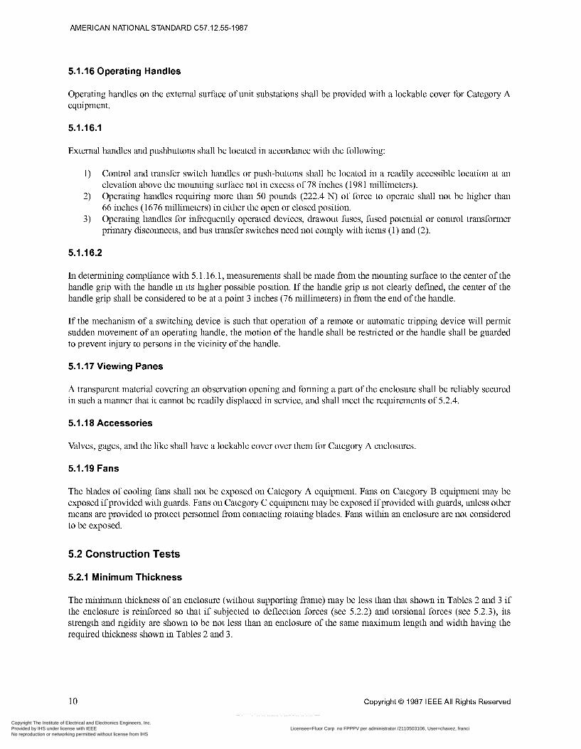
5.1.16 Operating Handles
Operating handles on the external surface of unit substations shall be provided with a lockable cover for Category A equipment.
5.1 . I 6.1
External handles and pushbuttons shall be located in accordance with the following:
1)
2)
3)
Control and transfer switch handles or push-buttons shall be located in a readily accessible location at an elevation above the mounting surface not in excess of 78 inches (198 1 millimeters). Operating handles requiring more than 50 pounds (222.4 N) of force to operate shall not be higher than 66 inches (1676 millimeters) in either the open or closed position. Operating handles for infiequently operated devices, drawout fuses, fused potential or control transformer primary disconnects, and bus transfer switches need not comply with items (1) and (2).
5.1 . I 6.2
In determining compliance with 5.1.16.1, measurements shall be made from the mounting surface to the center of the handle grip with the handle in its higher possible position. If the handle grip is not clearly defined, the center of the handle grip shall be considered to be at a point 3 inches (76 millimeters) in from the end of the handle.
If the mechanism of a switching device is such that operation of a remote or automatic tripping device will permit sudden movement of an operating handle, the motion of the handle shall be restricted or the handle shall be guarded to prevent injury to persons in the vicinity of the handle.
5.1.17 Viewing Panes
A transparent material covering an observation opening and forming a part of the enclosure shall be reliably secured in such a manner that it cannot be readily displaced in service, and shall meet the requirements of 5.2.4.
5.1 . I 8 Accessories
Valves, gages, and the like shall have a lockable cover over them for Category A enclosures.
5.1.19 Fans
The blades of cooling fans shall not be exposed on Category A equipment. Fans on Category B equipment may be exposed if provided with guards. Fans on Category C equipment may be exposed if provided with guards, unless other means are provided to protect personnel from contacting rotating blades. Fans within an enclosure are not considered to be exposed.
5.2 Construction Tests
5.2.1 Minimum Thickness
The minimum thickness of an enclosure (without supporting frame) may be less than that shown in Tables 2 and 3 if the enclosure is reinforced so that if subjected to deflection forces (see 5.2.2) and torsional forces (see 5.2.3), its strength and rigidity are shown to be not less than an enclosure of the same maximum length and width having the required thickness shown in Tables 2 and 3.
10 Copyright O 1987 IEEE All Rights Reserved
Copyright The Institute of Electrical and Electronics Engineers, Inc. Provided by IHS under license with IEEE Licensee=Fluor Corp no FPPPV per administrator /2110503106, User=chavez, franci
Not for Resale, 06/20/2012 09:23:11 MDTNo reproduction or networking permitted without license from IHS
--`,`````,``,,`,,`,,,,,,,`,`,,,-`-`,,`,,`,`,,`---
AMERICAN NATIONAL STANDARD C57.12.55-1987
5.2.2 Deflection Test
The test described in 5.2.3(2) shall be made on the end, side, and rear walls of each enclosure. Since the forces and limits are not specified, the force on each wall of both the test and reference enclosures shall be sufficient to result in a measurable deflection of the test enclosure.
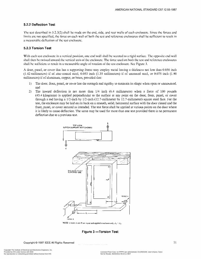
5.2.3 Torsion Test
With each test enclosure in a vertical position, one end wall shall be secured to a rigid surface. The opposite end wall shall then be twisted around the vertical axis of the enclosure. The force used on both the test and reference enclosures shall be sufficient to result in a measurable angle of rotation of the test enclosure. See Figure 3.
A door, panel, or cover that has a supporting frame may employ metal having a thickness not less than 0.056 inch (1.42 millimeters) if of zinc-coated steel, 0.053 inch (1.35 millimeters) if of uncoated steel, or 0.075 inch (1.90 millimeters) if of aluminum, copper, or brass, provided that:
The door, front, panel, or cover has the strength and rigidity to maintain its shape when open or unmounted, and The inward deflection is not more than 1/4 inch (6.4 millimeters) when a force of 100 pounds (45.4 kilograms) is applied perpendicular to the surface at any point on the door, front, panel, or cover through a rod having a 1/2-inch by 1/2-inch (12.7-millimeter by 12.7-millimeter) square steel face. For the test, the enclosure may be laid on its back on a smooth, solid, horizontal surface with the door closed and the front, panel, or cover secured as intended. The test force shall be applied at various points on the door where it is likely to cause deflection. The same may be used for more than one test provided there is no permanent deflection due to a previous test.
1)
2)
TOP VIEW (UPPER SUPPORT N O T SHOWN)
FORCE ô
NOTE: Forces A and B are equal and applied simultaneously, d l = d Z .
Figure 3 -Torsion Test
Copyright O 1987 IEEE All Rights Reserved 11
Copyright The Institute of Electrical and Electronics Engineers, Inc. Provided by IHS under license with IEEE Licensee=Fluor Corp no FPPPV per administrator /2110503106, User=chavez, franci
Not for Resale, 06/20/2012 09:23:11 MDTNo reproduction or networking permitted without license from IHS
--`,`````,``,,`,,`,,,,,,,`,`,,,-`-`,,`,,`,`,,`---
AMERICAN NATIONAL STANDARD C57.12.55-1987
5.2.4 Viewing Panes
Viewing panes as indicated in 5.1.17 shall not shatter, crack, or become dislodged when both sides of the viewing pane in turn are subjected to the following tests:
A force of 200 pounds (91 kilograms) shall be exerted perpendicular to the surface in which the viewing pane is mounted. This force shall be evenly distributed over an area of 16 square inches (0.010 square meters) as nearly square as possible and as near the geometric center of the viewing pane as possible. If the viewing pane has an area less than 16 square inches (0.010 square meter), the force shall be evenly distributed over the entire viewing area. The 200- pound (91-kilogram) force shall be sustained for a period of 1 minute.
The viewing pane shall be subjected to an impact of 5 foot-pounds (6.8 Joules) using a steel ball weighing approximately 1.18 pounds (0.535 kilogram) and approximately 2 inches (50 millimeters) in diameter.
5.2.4.3
Separate samples may be used for each of the tests described in 5.2.4.1 and 5.2.4.2.
5.3 Enclosure Security
5.3.1 Equipment
Enclosure security tests shall be conducted with the following equipment:
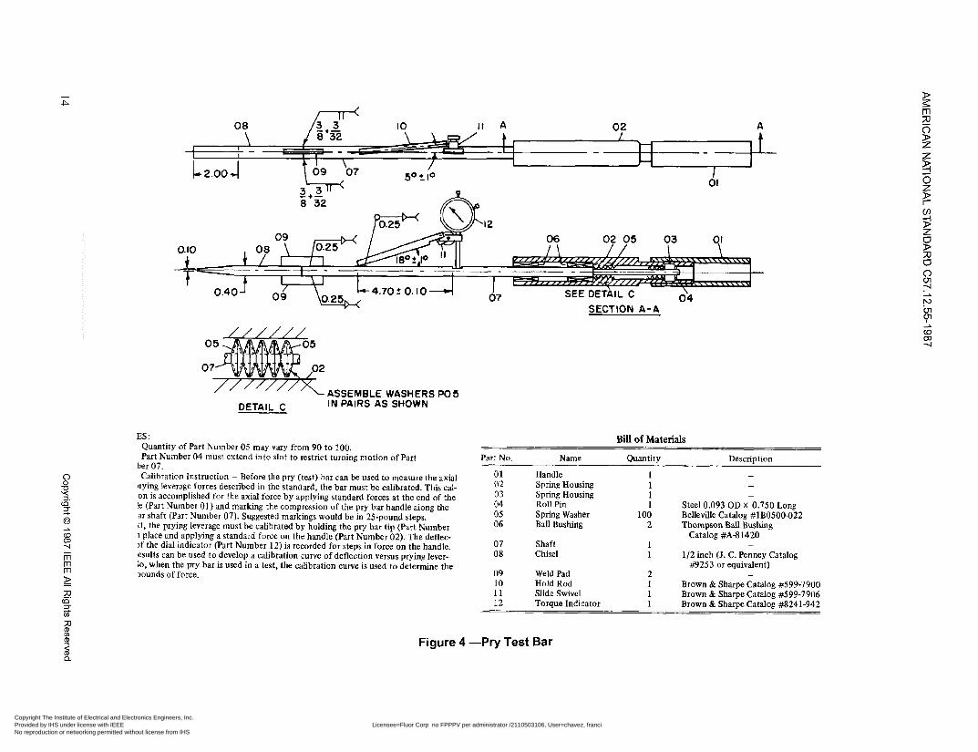
The pry bar used for the pry tests shall be constructed in accordance with Figure 4. The pry bar consists of the specified pry tip welded to a pry bar. The handle shall be mounted so it can slide only in an axial direction, restrained by a stack of Belleville washers. The forces described in the following sections shall be applied to the handle.
When an axial force is applied to the handle, the stack of Belleville washers shall be compressed. The amount of compression is a measure of the magnitude of the axial force applied. Using the scale of another force-measuring device, the pry bar can be calibrated to measure the axial force used to force the tip into the joint under test.
The prying leverage applied can be measured indirectly by measuring the deflection of the pry bar. The dial indicator shall be mounted on the pry bar and set to measure deflection of a certain length of the bar. A calibration can be made that will result in a table or curve showing prying leverage versus reading of the dial indicator.
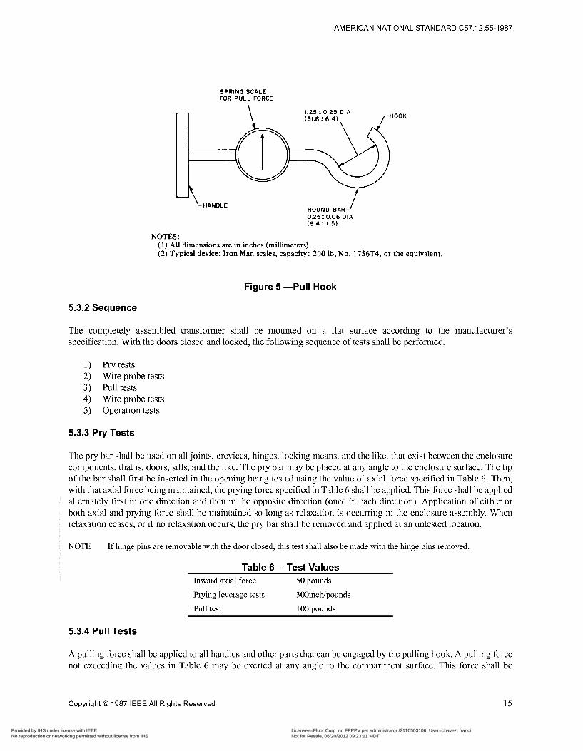
The pull bar shown in Figure 5 shall be used in the pull tests. The pulling means is designed to measure the axial pull in pounds and shall be constructed in accordance with Figure 5.
The probing wire shall be 10 AWG bare hard-drawn solid copper wire, 10 feet long.
12 Copyright O 1987 IEEE All Rights Reserved
Copyright The Institute of Electrical and Electronics Engineers, Inc. Provided by IHS under license with IEEE Licensee=Fluor Corp no FPPPV per administrator /2110503106, User=chavez, franci
Not for Resale, 06/20/2012 09:23:11 MDTNo reproduction or networking permitted without license from IHS
--`,`````,``,,`,,`,,,,,,,`,`,,,-`-`,,`,,`,`,,`---
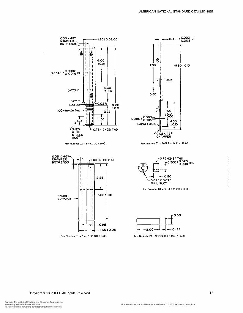
AMERICAN NATIONAL STANDARD C57.12.55-1987
0.0000 0.8740 t 0.00ig ID
0.670 ID
0.02 R 1.00 OD
1.00- 16-2A THO
1- 1.30t 0.02 OD
D io
9 -10 2 0.01
i L 0.75- 12- 28 THO
Part Number 02 - Steel 1.30 X 9.00
t
KNURL SURFACE 4
T I 5.00? 0.10
1 -0.95
- I . 35 ? 0.05
Part Number O1 - Steel 1.35 OD X 5.00
I- O. 50
0.093 f 0.010
CO. 499t ID
1 i8.e
- 0.05
2 0.01
1 t 0.10
(0.02 x 450 CHAMFER
Part Number 07 - Drill Rod 0.50 X 18.80
0.75-12-2A THO O ,300 t g;s$: TH D
-E37 4 L- 0.50 0 .075 X 0.075 MILL SLOT
Part Number 03 - Steel 0.75 OD X 0.50
r 0.50
Part Number 09 - Steel 0.188 X 0.50 X 2.00
Copyright O 1987 IEEE All Rights Reserved 13
Copyright The Institute of Electrical and Electronics Engineers, Inc. Provided by IHS under license with IEEE Licensee=Fluor Corp no FPPPV per administrator /2110503106, User=chavez, franci
Not for Resale, 06/20/2012 09:23:11 MDTNo reproduction or networking permitted without license from IHS
--`,`````,``,,`,,`,,,,,,,`,`,,,-`-`,,`,,`,`,,`---
c P
- rn rn rn
o2 A
o1
SECTION A - A
z o;
(B
2
DETAIL C ASSEMBLE WASHERS IN PAIRS AS SHOWN
PO 5
ES: Quantity of Part Number 05 may vary from 90 to 100. Part Number 04 must extcnd into slot to restrict turning motion of Part
ber 07. Calibration Instruction - Before the pry (test) bar can be used to measure the axial
mying leverage forces described in the standard, the bar must be calibrated. This cai- on is accomplished for the axial force by applying standard forces at the end of the le (Part Number 01) and marking the compression of the pry bar handle along the ar shaft (Part Number 07). Suggested markings would be in 25-pound steps. [t, the prying leverage must be calibrated by holding the pry bar tip (Part Number I place and applying a standard force on the handle (Part Number 02). The deflec- If the dial indicator Part Number 12) is recorded for steps in force on the handle. csults can be used to develop a calibration curve of deflection versus prying lever- ;o, when the pry bar is used in a test, the calibration curve is used to determine the 3ounds of force.
Bill of Materiais
Part No. Name Quantity Description - o1 Handle I
02 Spring Housing 1 03 Spring Housing 1
05 Spring Washer 100
- -
04 Roll Pin 1 Steel 0.093 OD x 0.750 Long
06 Ball Bushing Belleville Catalog #lB0500-022
2 Thompson Ball Bushing Catalog #A41420
07 Shaft 08 Chisel
o9 Weld Pad 10 Hold Rod 11 Slide Swivel
- 1 1
2 -
1 1
1/2 inch (J. C. Penney Catalog H 2 5 3 or equivalent)
Brown & Sharpe Catalog #599-7900 Brown & Sharpe Catalog #S99-7906 Brown & Sharpe Catalog #8241-942 12 Torque Indicator 1
Figure 4 -Pry Test Bar
Copyright The Institute of Electrical and Electronics Engineers, Inc. Provided by IHS under license with IEEE Licensee=Fluor Corp no FPPPV per administrator /2110503106, User=chavez, franci
Not for Resale, 06/20/2012 09:23:11 MDTNo reproduction or networking permitted without license from IHS
--`,`````,``,,`,,`,,,,,,,`,`,,,-`-`,,`,,`,`,,`---
AMERICAN NATIONAL STANDARD C57.12.55-1987
c
-
SPRING SCALE FOR PULL FORCE
HOOK 1.25 Z 0 . 2 5 DIA (3i.8! 6.4)
HANDLE ROUND BAR 0.25: 0.06 DIA (6.41 1.5)
NOTES: (1) All dimensions are in inches (millimeters). (2) Typical device: Iron Man scales, capacity: 200 Ib, No. 1756T4, or the equivalent.
Figure 5 -Pull Hook
5.3.2 Sequence
The completely assembled transformer shall be mounted on a flat surface according to the manufacturer’s specification. With the doors closed and locked, the following sequence of tests shall be performed.
1) Pry tests 2) Wire probe tests 3) Pull tests 4) Wire probe tests 5) Operation tests
5.3.3 Pry Tests
The pry bar shall be used on all joints, crevices, hinges, locking means, and the like, that exist between the enclosure components, that is, doors, sills, and the like. The pry bar may be placed at any angle to the enclosure surface. The tip of the bar shall first be inserted in the opening being tested using the value of axial force specified in Table 6. Then, with that axial force being maintained, the prying force specified in Table 6 shall be applied. This force shall be applied alternately first in one direction and then in the opposite direction (once in each direction). Application of either or both axial and prying force shall be maintained so long as relaxation is occurring in the enclosure assembly. When relaxation ceases, or if no relaxation occurs, the pry bar shall be removed and applied at an untested location.
NOTE ~ If hinge pins are removable with the door closed, this test shall also be made with the hinge pins removed
Table 6- Test Values Inward axial force 50 pounds
Prying leverage tests 300inchípounds
Pull test 1 O0 pounds
5.3.4 Pull Tests
A pulling force shall be applied to all handles and other parts that can be engaged by the pulling hook. A pulling force not exceeding the values in Table 6 may be exerted at any angle to the compartment surface. This force shall be
Copyright O 1987 IEEE All Rights Reserved 15
Copyright The Institute of Electrical and Electronics Engineers, Inc. Provided by IHS under license with IEEE Licensee=Fluor Corp no FPPPV per administrator /2110503106, User=chavez, franci
Not for Resale, 06/20/2012 09:23:11 MDTNo reproduction or networking permitted without license from IHS
--`,`````,``,,`,,`,,,,,,,`,`,,,-`-`,,`,,`,`,,`---

AMERICAN NATIONAL STANDARD C57.12.55-1987
maintained during any relaxation of the enclosure assembly. When relaxation ceases, or if no relaxation occurs, the pull test shall be terminated. The hook shall then be inserted into any other handle or other part that it can engage, and the test repeated. Any handle or part shall be tested only once.
NOTE ~ If hinge pins are removable with the door closed, this test shall also be made with the hinge pins removed
5.3.5 Wire Probe Tests
Following the pry and pull tests described in 5.3.3 and 5.3.4, the enclosure shall be penetrated with the probe wire. This penetration may be tried at any enclosure crevice or joint. The wire shall be straight with no prebends and shall be gripped by the tester with bare hands. If the wire enters the joint, the wire shall be continually pushed until it can no longer be pushed or until it has entered the enclosure. This test is passed if an inspection determines that the probing wire either has not entered the enclosure or the probing wire is restricted by a visible barrier from intrusion into the interior of the enclosure.
5.3.6 Operation Test
Following the foregoing tests, the enclosure shall be capable of closed and locked without loss of security.
5.3.7 Test Values
The minimum test values for which entry must be prevented shal
ieing easily unlocked and opened and, also, easily
be in accordance with Table 6.
6. Outdoor Enclosures - Requirements
6.1 Construction
A nonmetallic enclosure shall be considered on the basis of the effect of exposure to ultraviolet light and water (standard in preparation).
Copper, bronze, and brass containing not less than 80 percent copper or stainless steel may be used without additional protection against corrosion. Aluminum (sheet, extrusion, or casting), diecast zinc, or another metal shall be of a grade or alloy known to be nonsusceptible to corrosion, or shall be subjected to appropriate tests, or shall be additionally protected from corrosion.
Aluminum in an outdoor enclosure shall be located so that it will not be in contact with the mounting pad.
Hinges and other attachments shall be resistant to corrosion. Metals shall not be used in combinations that result in galvanic action that adversely affects any part of the device.
If an outdoor enclosure has any opening for passage of a wire or bus bar to a switchboard section or to a wireway, auxiliary gutter, or busway, a suitable gasket or other means shall be provided that will prevent the entrance of water at such opening. If the opening is for attachment of a busway, the outdoor enclosure and the busway shall be investigated together to determine that water does not enter along the bus bars.
Outdoor construction requiring a gasketed joint shall be investigated to determine whether or not it is suitable for the particular application.
A gasket of an elastomeric or thermoplastic material or a composition gasket utilizing an elastomeric material employed to make an enclosure suitable for outdoor use shall be adequately resistant to aging as determined by the following accelerated-aging tests.
16 Copyright O 1987 IEEE All Rights Reserved
Copyright The Institute of Electrical and Electronics Engineers, Inc. Provided by IHS under license with IEEE Licensee=Fluor Corp no FPPPV per administrator /2110503106, User=chavez, franci
Not for Resale, 06/20/2012 09:23:11 MDTNo reproduction or networking permitted without license from IHS
--`,`````,``,,`,,`,,,,,,,`,`,,,-`-`,,`,,`,`,,`---
AMERICAN NATIONAL STANDARD C57.12.55-1987
A gasket of rubber or neoprene, or a composition thereof, shall be exposed for 96 hours to oxygen at a pressure of 300 pounds per square inch (0.21 kilograms per square millimeter or 2.1 mega-newtons per square meter) and a temperature of 70°C (158°F). The gasket shall be considered adequately resistant to aging if there is no visible evidence of deterioration such as softening, hardening, or cracking after flexing. (See ANSILJL 347-1985, Section 32.)
A gasket of thermoplastic material, or a composition thereof, may be considered acceptable after consideration of the effects of heat aging, distortion under conditions of use, and the means of securing the gasket to the cover or enclosure.
External hinged doors or covers for outdoor equipment shall be provided with stops to hold them in the open position or shall be removable.
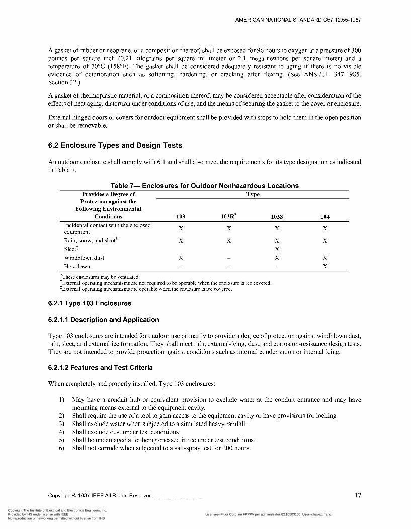
6.2 Enclosure Types and Design Tests
An outdoor enclosure shall comply with 6.1 and shall also meet the requirements for its type designation as indicated in Table 7.
Table 7- Enclosures for Outdoor Nonhazardous Locations Provides a Degree of Type
Protection against the Following Environmental
Incidental contact with the enclosed equipment
Conditions 103 103R* 103s 104
X X X X
Rain, snow, and sleet? Sleet1 Windblown dust Hosedown
X X X
X ~
X X
*These enclosures may be ventilated. +External operating mechanisms are not required to be operable when the enclosure is ice covered. $External operating mechanisms are operable when the enclosure is ice covered.
6.2.1 Type 103 Enclosures
6.2.1 . I Description and Application
Type 103 enclosures are intended for outdoor use primarily to provide a degree of protection against windblown dust, rain, sleet, and external ice formation. They shall meet rain, external-icing, dust, and corrosion-resistance design They are not intended to provide protection against conditions such as internal condensation or internal icing.
6.2.1.2 Features and Test Criteria
When completely and properly installed, Type 103 enclosures:
1)
2) 3) 4) 5) 6)
May have a conduit hub or equivalent provision to exclude water at the conduit entrance and may mounting means external to the equipment cavity. Shall require the use of a tool to gain access to the equipment cavity or have provisions for locking. Shall exclude water when subjected to a simulated heavy rainfall. Shall exclude dust under test conditions. Shall be undamaged after being encased in ice under test conditions. Shall not corrode when subjected to a salt-spray test for 200 hours.
tests.
have
Copyright O 1987 IEEE All Rights Reserved 17
Copyright The Institute of Electrical and Electronics Engineers, Inc. Provided by IHS under license with IEEE Licensee=Fluor Corp no FPPPV per administrator /2110503106, User=chavez, franci
Not for Resale, 06/20/2012 09:23:11 MDTNo reproduction or networking permitted without license from IHS
--`,`````,``,,`,,`,,,,,,,`,`,,,-`-`,,`,,`,`,,`---
AMERICAN NATIONAL STANDARD C57.12.55-1987
6.2.1.3 Design Tests
Type 103 enclosures shall be tested and evaluated by the following:
1) Spray test described in 7.1. 2) Dust test described in 7.2. 3) External-icing test described 7.3. 4) Corrosion-resistance test described 7.5.
6.2.2 Type 103R Enclosures
6.2.2.1 Description and Application
Type 103R enclosures are intended for outdoor use primarily to provide a degree of protection against falling rain, sleet, and external ice formation. They shall meet rod-entry, rain, external-icing, and corrosion-resistance design tests. They are not intended to provide protection against conditions such as dust, internal condensation, or internal icing.
6.2.2.2 Features and Test Criteria
6.2.2.2.1 Nonventilated Enclosures
When completely and properly installed, Type 103R non-ventilated enclosures:
1)
2)
3)
4) 5)
Shall permit no water to enter the equipment cavity at a level higher than the lowest live part except if constructed to divert water from live parts. Insulation and wiring shall have provision for drainage. Shall remain undamaged after being encased in ice under test conditions that are intended to simulate freezing rain. May have a conduit hub or equivalent provision to exclude water at the conduit entrance if the entrance is above the lowest live part. Shall require the use of a tool to gain access to the equipment cavity or have provisions for locking. Shall prevent the entrance of a rod having a diameter of 0.125 inch (3.175 millimeters), except that, if the distance from the opening to the nearest live part is greater than that given in Table 5, the opening may permit the entry of a rod having a diameter not greater than 0.500 inch (12.70 millimeters). Shall not corrode when subjected to a salt-spray test for 200 hours. 6)
6.2.2.2.2 Ventilated Enclosures
Type 103R ventilated enclosures have the same provisions as nonventilated enclosures except that they have ventilated openings. These openings prevent the entrance of a rod having a diameter of 0.500 inch (12.70 millimeters), except that, if the distance from the opening to any live part is greater than that given in Table 5, the opening may permit the entry of a rod having a diameter not greater than 0.750 inch (19.05 millimeters).
6.2.2.3 Design Tests
Type 103R enclosures shall be tested and evaluated by the following:
1) 2) 3) 4)
Rod-entry test described in 6.2.2.2.1(5). Spray test described in 7.1. External-icing test described in 7.3. Corrosion-resistance test described in 7.5.
18 Copyright O 1987 IEEE All Rights Reserved
Copyright The Institute of Electrical and Electronics Engineers, Inc. Provided by IHS under license with IEEE Licensee=Fluor Corp no FPPPV per administrator /2110503106, User=chavez, franci
Not for Resale, 06/20/2012 09:23:11 MDTNo reproduction or networking permitted without license from IHS
--`,`````,``,,`,,`,,,,,,,`,`,,,-`-`,,`,,`,`,,`---
AMERICAN NATIONAL STANDARD C57.12.55-1987
6.2.3 Type 103s Enclosures
6.2.3.1 Description and Application
Type 103s enclosures are intended for outdoor use primarily to provide a degree of protection against windblown dust, rain, and sleet and to provide for operation of external mechanisms when ice laden. They shall meet rain, external- icing, dust, and corrosion-resistance design tests. They are not intended to provide protection against conditions such as internal condensation or internal icing.
6.2.3.2 Features and Test Criteria
When completely and properly installed, Type 103s enclosures:
1) 2) 3) 4) 5) 6)
7)
Shall exclude water when subjected to a simulated heavy rainfall. Shall exclude dust under test conditions that are intended to simulate windblown dust. May have a conduit hub or equivalent provision to exclude water at the conduit entrance. If wall mounted, shall have mounting means external to the equipment cavity. Shall require the use of a tool to gain access to the equipment cavity or have provisions for locking. Shall have external operating mechanisms with the ability to withstand removal of ice by a hand tool. Auxiliary means may be provided to break the ice and external mechanisms. Shall not corrode when subjected to a salt-spray test for 200 hours.
6.2.3.3 Design Tests
Type 103s enclosures shall be tested and evaluated by the following:
1) 2) 3) 4)
Spray test described in 7.1. Dust test described in 7.2. External-icing test described in 7.3. Corrosion-resistance test described in 7.5.
6.2.4 Type 104 Enclosures
6.2.4.1 Description and Application
Type 104 enclosures are intended for indoor or outdoor use primarily to provide a degree of protection against windblown dust, rain, sleet, splashing water, and hose-directed water. They shall meet hosedown, dust, external-icing, and corrosion-resistance design tests. They are not intended to provide protection against conditions such as internal condensation or internal icing.
6.2.4.2 Features and Test Criteria
When completely and properly installed, Type 104 enclosures:
1)
2) 3) 4) 5)
Shall exclude water when subjected to a stream of water from a 25.4-millimeter (l-inch) nozzle at a rate of 246 liters per minute (65 gallons per minute) for the length of time dependent on the enclosure size. Shall exclude dust under test conditions. Shall not corrode when subjected to a salt-spray test for 200 hours. May have a conduit hub or equivalent provision to exclude water at the conduit entrance. If wall mounted, shall have mounting means external to the equipment cavity.
NOTE ~ External operating mechanisms are not required to be operable when the enclosure is ice covered.
Copyright O 1987 IEEE All Rights Reserved 19
Copyright The Institute of Electrical and Electronics Engineers, Inc. Provided by IHS under license with IEEE Licensee=Fluor Corp no FPPPV per administrator /2110503106, User=chavez, franci
Not for Resale, 06/20/2012 09:23:11 MDTNo reproduction or networking permitted without license from IHS
--`,`````,``,,`,,`,,,,,,,`,`,,,-`-`,,`,,`,`,,`---
AMERICAN NATIONAL STANDARD C57.12.55-1987
6.2.4.3 Design Tests
Type 104 enclosures shall be tested and evaluated by the following:
1) 2) 3) 4)
Dust test described in 7.2. External-icing test described in 7.3. Hosedown test described in 7.4. Corrosion-resistance test described in 7.5.
7. Outdoor Enclosures - Design Tests
7.1 Spray Test
An enclosure marked for outdoor use shall be subjected to the following spray test:
7.1.1 Methods
1) The enclosure to be tested shall be fully equipped and complete with all appurtenances such as roof bushings, conduits, and the like, and mounted in the intended manner in the area to be supplied with artificial precipitation. For multiple unit construction, a minimum of two units shall be used to test the joints between units including a roof joint. The tightening torque for rigid conduit threaded into the opening in the enclosure shall be 800 pound-inches (9.2 kilogram-meters) for 3/4-inch and smaller trade sizes, 1000 pound-inches (1 1.5 kilogram-meters) for 1-, 1-1/4-, and 1-1/2-inch trade sizes, and 1600 pound-inches (18.4 kilogram-meters) for 2-inch and larger trade sizes. The artificial precipitation shall be supplied by a sufficient number of nozzles to produce a uniform spray over the entire surface or surfaces under test. The various vertical surfaces of an enclosure may be tested separately or collectively, provided that a uniform spray is simultaneously applied to both of the following: a) The roof surface, from nozzles located at a suitable height. b) The floor outside the enclosure for a distance of approximately 1 meter (3 feet) in front of the surface
under test with the enclosure located at its normal height above the floor level. The nozzles used for this test shall deliver a square-shaped spray pattern with uniform .spray distribution and shall have a capacity of at least 450 cubic centimeters per second (7.1 gallons per minute) at 41.4 newtons per square centimeter (60 pounds per square inch) pressure, and a spray angle spread of approximately 75 degrees. The centerline of the nozzles shall be inclined downward so that the top of the spray is horizontal as it is directed toward the vertical and roof surfaces being tested. The pressure at the nozzles shall be a minimum of 41.4 newtons per square centimeter (60 pounds per square inch) under flow conditions. [This is approximately equivalent to rain driven by a 29-meter-per- second (65-mile-per-hour) wind.] The quantity of water applied to each surface under test shall be at least 0.5 centimeter (0.2 inch) per unit surface per minute, and each surface so tested shall receive this rate of artificial precipitation for 5 minutes. The spray nozzle shall not be more than 3 meters (10 feet) from the nearest vertical surface under test.
2)
3)
4)
5)
7.1.2 Evaluation
At the conclusion of the test, an enclosure shall be considered to have met the requirements of this test if there is:
1) 2) 3)
No water visibly observable on primary or secondary insulation. No water visibly observable on any electrical components or mechanisms of the assembly. No significant accumulation of water retained by the structure or other noninsulating parts (to minimize corrosion).
20 Copyright O 1987 IEEE All Rights Reserved
Copyright The Institute of Electrical and Electronics Engineers, Inc. Provided by IHS under license with IEEE Licensee=Fluor Corp no FPPPV per administrator /2110503106, User=chavez, franci
Not for Resale, 06/20/2012 09:23:11 MDTNo reproduction or networking permitted without license from IHS
--`,`````,``,,`,,`,,,,,,,`,`,,,-`-`,,`,,`,`,,`---
AMERICAN NATIONAL STANDARD C57.12.55-1987
7.2 Dust Tests
7.2.1 Dust-Blast (Alternate to the Atomized Water Method)
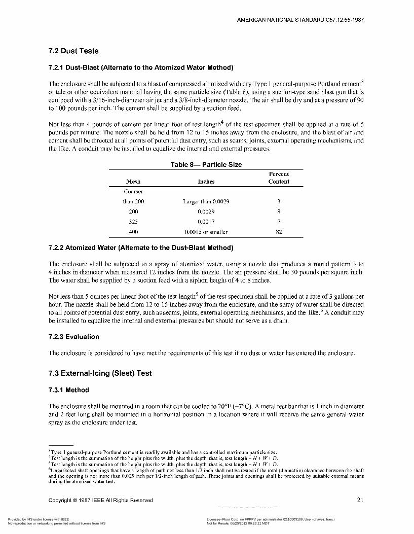
The enclosure shall be subjected to a blast of compressed air mixed with dry Type 1 general-purpose Portland cement3 or talc or other equivalent material having the same particle size (Table S), using a suction-type sand blast gun that is equipped with a 3/16-inch-diameter air jet and a 3/8-inch-diameter nozzle. The air shall be dry and at a pressure of 90 to 100 pounds per inch. The cement shall be supplied by a suction feed.
Not less than 4 pounds of cement per linear foot of test length4 of the test specimen shall be applied at a rate of 5 pounds per minute. The nozzle shall be held from 12 to 15 inches away from the enclosure, and the blast of air and cement shall be directed at all points of potential dust entry, such as seams, joints, external operating mechanisms, and the like. A conduit may be installed to equalize the internal and external pressures.
Table 8- Particle Size Percent
Mesh Inches Content
Coarser
than 200 Larger than 0.0029
200 0.0029
325 0.0017
400 0.0015 or smaller
3
8
7
82
7.2.2 Atomized Water (Alternate to the Dust-Blast Method)
The enclosure shall be subjected to a spray of atomized water, using a nozzle that produces a round pattern 3 to 4 inches in diameter when measured 12 inches from the nozzle. The air pressure shall be 30 pounds per square inch. The water shall be supplied by a suction feed with a siphon height of 4 to 8 inches.
Not less than 5 ounces per linear foot of the test length5 of the test specimen shall be applied at a rate of 3 gallons per hour. The nozzle shall be held from 12 to 15 inches away from the enclosure, and the spray of water shall be directed to all points of potential dust entry, such as seams, joints, external operating mechanisms, and the like.6 A conduit may be installed to equalize the internal and external pressures but should not serve as a drain.
7.2.3 Evaluation
The enclosure is considered to have met the requirements of this test if no dust or water has entered the enclosure.
7.3 External-Icing (Sleet) Test
7.3.1 Method
The enclosure shall be mounted in a room that can be cooled to 20°F (-7°C). A metal test bar that is 1 inch in diameter and 2 feet long shall be mounted in a horizontal position in a location where it will receive the same general water spray as the enclosure under test.
3Type 1 general-purpose Portland cement is readily available and has a controlled maximum particle size 4Test length is the summation of the height plus the width, plus the depth, that is, test length = H + W + D 5Test length is the summation of the height plus the width, plus the depth, that is, test length = H + W + D %Jngasketed shaft openings that have a length of path not less than 1/2 inch shall not be tested if the total (diametric) clearance between the shaft and the opening is not more than O 005 inch per 1R-inch length of path These joints and openings shall be protected by suitable external means during the atomized water test
Copyright O 1987 IEEE All Rights Reserved 21
Copyright The Institute of Electrical and Electronics Engineers, Inc. Provided by IHS under license with IEEE Licensee=Fluor Corp no FPPPV per administrator /2110503106, User=chavez, franci
Not for Resale, 06/20/2012 09:23:11 MDTNo reproduction or networking permitted without license from IHS
--`,`````,``,,`,,`,,,,,,,`,`,,,-`-`,,`,,`,`,,`---
AMERICAN NATIONAL STANDARD C57.12.55-1987
Provision shall be made for 45 degrees from the vertical. that provide between 1 and 2
’ spraying the entire enclosure from above with water at an angle of approximately The water shall be between 32°F (0°C) and 37°F (3°C). (As a guide, spraying facilities gallons per hour per square foot of area to be sprayed have been found effective.)
The room temperature shall be lowered to 35°F (2°C). The spray of water shall be started and continued for at least 1 hour, maintaining the room temperature between 33°F (1°C) and 37°F (3°C).
At the end of this time, the room temperature shall be lowered to between 20°F (-7°C) and 27°F (-3°C) without discontinuing the water spray. (The rate of change in the room temperature is not critical and shall be whatever is obtainable with the cooling means employed.) The water spray shall be controlled so as to cause ice to build up on the bar at a rate of approximately 1/4 inch per hour and shall be continued until 3/4 inch of ice has formed on the top surface of the bar. The spray shall then be discontinued, but the room temperature shall be maintained between 20°F (-7°C) and 27°F (-3°C) for 3 hours to ensure that all parts of the enclosure and ice coatings have been equalized to a constant temperature.
7.3.2 Evaluation
The enclosure and its external mechanisms shall be considered acceptable if
1) While ice laden, they can be manually operated by one person without any damage to the enclosure, the enclosed equipment, or the mechanism. When an auxiliary mechanism is provided to break the ice, it shall be included and utilized in the test. A separate test is required for each maintained position of each external operator; if necessary, it should be possible to gain access to the enclosure interior using an appropriate hand tool without causing functional damage to the enclosure. They are found to be undamaged after the ice has melted. Enclosures that have no external cavities to trap water are considered to be acceptable and need not be tested.
2)
7.4 Hosedown Test
7.4.1 Method
The enclosure and its external mechanisms shall be subjected to a stream of water from a hose that has a 1-inch nozzle and that delivers at least 65 gallons per minute. The water shall be directed at all joints from all angles from a distance of 10 to 12 feet for a period of time equal to 48 seconds times the test length.7 A conduit may be installed to equalize internal and external pressures but should not serve as a drain.
7.4.2 Evaluation
The enclosure is considered to have met the requirements of this test if no water has entered the enclosure.
7.5 Corrosion-Resistance Test
The corrosion-resistance test applies to all enclosures incorporating external ferrous parts. Nonferrous enclosures with no external ferrous parts need not be tested.
The enclosures or representative parts of enclosures shall be subjected to salt spray (fog) as described below:
7Test length is the summation of the height plus the width, plus the depth, that is, test length = H + W + D
22 Copyright O 1987 IEEE All Rights Reserved
Copyright The Institute of Electrical and Electronics Engineers, Inc. Provided by IHS under license with IEEE Licensee=Fluor Corp no FPPPV per administrator /2110503106, User=chavez, franci
Not for Resale, 06/20/2012 09:23:11 MDTNo reproduction or networking permitted without license from IHS
--`,`````,``,,`,,`,,,,,,,`,`,,,-`-`,,`,,`,`,,`---
AMERICAN NATIONAL STANDARD C57.12.55-1987
7.5.1 Test Apparatus
The test apparatus shall:
1)
2)
3)
4)
Consist of a fog chamber, a salt-solution reservoir, a supply of suitably conditioned compressed air, atomizing nozzles, support for the enclosure, provision for heating the chamber, and means of control. Not permit drops of solution that accumulate on the ceiling or cover of the chamber to fall on the enclosure being tested. Not permit drops of solution that fall from the enclosure to be returned to the solution reservoir for respraying. Be constructed of materials that will not affect the corrosiveness of the fog.
7.5.2 Salt Solution
The salt solution shall be prepared by dissolving 5 parts I 1 part by weight of salt in 95 parts of either distilled water or water containing not more than 200 parts per million of total solids. This salt shall be sodium chloride that is substantially free of metal and copper and that contains, when dry, not more than O. 1 percent of sodium iodide and not more than 0.3 percent of total impurities.
7.5.3 Air Supply
The compressed air supply to the nozzle(s) for atomizing the salt solution shall be free of oil and dirt and maintained between 10 and 25 pounds per square inch.
7.5.4 Condition in the Salt-Spray Chamber
The temperature of the salt-spray chamber shall be maintained at 95"F, plus 20°F or minus 30°F. The nozzle(s) shall be directed or baffled so that none of the spray can impinge directly on the enclosure being tested.
7.5.5 Continuity of Test
The test shall run continuously for 200 hours, that is, the chamber shall be closed and the spray operated continuously except for the short daily interruption necessary to inspect, rearrange, or remove the test specimens, to check and replenish the solution in the reservoir, and to make necessary recordings.
7.5.6 Cleaning and Inspection of Tested Enclosure
At the end of the test, the specimens shall be removed from the chambers and washed in clean running water that is not warmer than 100°F to remove salt deposits from their surface, and then dried immediately. Corrosion products, other than rust, may be removed by light brushing if required to observe the condition of the underlying stratum.
7.5.7 Evaluation
The enclosure is considered to have met the requirements of this test if there is no pitting, cracking, or other deterioration more severe than that resulting from a similar test on passivated AIS1 Type 304 stainless steel after 200 hours of exposure.
Copyright O 1987 IEEE All Rights Reserved 23
Copyright The Institute of Electrical and Electronics Engineers, Inc. Provided by IHS under license with IEEE Licensee=Fluor Corp no FPPPV per administrator /2110503106, User=chavez, franci
Not for Resale, 06/20/2012 09:23:11 MDTNo reproduction or networking permitted without license from IHS
--`,`````,``,,`,,`,,,,,,,`,`,,,-`-`,,`,,`,`,,`---
AMERICAN NATIONAL STANDARD C57.12.55-1987
8. Enclosures - Marking
Transformer enclosures shall be marked with the following:
1) 2) 3)
The nameplate in accordance with ANSUIEEE C57.12.01-1979 The exposure category see (4.2) The type designation for outdoor enclosures only (see Table 7)
Category A and B enclosures shall have appropriate caution signs in accordance with ANSI/NFPA 70-1987.
The front and rear of all equipment enclosures not exceeding 15 feet in length and having doors or removable covers permitting access to high-voltage compartments shall be marked with a caution or warning sign. Longer enclosures shall be so marked at 15-fOOt intervals.
Enclosures containing high-voltage parts (over 600 volts) shall be permanently marked by the manufacturer with exterior warning ?High voltage? or ?Warning ~ High voltage.?
The operating voltages of exposed live parts shall be permanently marked on the equipment.
Nonloadbreak devices shall be interlocked or have a caution sign: ?Warning ~ Do Not Open under Load.?
Fuses that can be energized by backfeed shall have a caution sign: ?Warning ~ Fuses May Be Energized by Backfeed.?
9. Conformance Tests
9.1 Definition
Conformance tests are those that are made specifically to demonstrate conformity with applicable standards.
9.2 Require me nts
The conformance tests for dry-type transformers are those listed in Table 9. These tests shall be made in accordance with ANSUIEEE C57.12.91-1979 (under revision). Each sample shall first be subjected to preliminary tests as designated by Table 9.
24 Copyright O 1987 IEEE All Rights Reserved
Copyright The Institute of Electrical and Electronics Engineers, Inc. Provided by IHS under license with IEEE Licensee=Fluor Corp no FPPPV per administrator /2110503106, User=chavez, franci
Not for Resale, 06/20/2012 09:23:11 MDTNo reproduction or networking permitted without license from IHS
--`,`````,``,,`,,`,,,,,,,`,`,,,-`-`,,`,,`,`,,`---
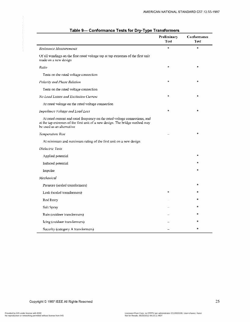
AMERICAN NATIONAL STANDARD C57.12.55-1987
Table 9- Conformance Tests for Dry-Type Transformers Preliminary Conformance
Test Test
Resistance Measurements *
Of all windings on the first rated voltage tap at tap extremes of the first unit made on a new design
Ratio
Tests on the rated voltage connection
Polarity and Phase Relation
Tests on the rated voltage connection
No Load Losses and Excitation Current
At rated voltage on the rated voltage connection
Impedance Voltage and Load Loss
At rated current and rated frequency on the rated voltage connections, and at the tap extremes of the first unit of a new design. The bridge method may be used as an alternative
Temperature Rise
At minimum and maximum rating of the first unit on a new design
Dielectric Tests
Applied potential
Induced potential
Impulse
Mechanical
Pressure (sealed transformers)
Leak (sealed transformers)
Rod Entry
Salt Spray
Rain (outdoor transformers)
Icing (outdoor transformers)
Security (category A transformers)
*
*
*
Copyright O 1987 IEEE All Rights Reserved 25
Copyright The Institute of Electrical and Electronics Engineers, Inc. Provided by IHS under license with IEEE Licensee=Fluor Corp no FPPPV per administrator /2110503106, User=chavez, franci
Not for Resale, 06/20/2012 09:23:11 MDTNo reproduction or networking permitted without license from IHS
--`,`````,``,,`,,`,,,,,,,`,`,,,-`-`,,`,,`,`,,`---
AMERICAN NATIONAL STANDARD C57.12.55-1987
I O . Certification Guidelines
10.1 Sampling
A transformer from each design family, based on winding design, temperature class capacity, and lead configuration shall be selected for certification.
Winding design can be considered as one design if it is of similar construction and it can be demonstrated that the voltage stresses do not exceed those used in evaluating the system.
The full range of transformers may be grouped into capacity groups for the selection of a representative transformer for testing. The following tabulation is a guide for establishing the capacity groups for the purpose of selecting samples; other group groupings of capacity may be selected if agreed to by those concerned.
Through 75 kVA Over 75 kVA through 225 kVA Over 225 kVA through 500 kVA Over 500 kVA through 1,000 kVA Over 1,000 kVA through 2,500 kVA
The dielectric tests for a given transformer design configuration may be used for the tests for trans transformers with various lead configurations, such as articulated unit substation transformers' cable connection, unit substation transformers, and pad-mounted transformers, provided dielectric clearances are not less than those used in the tests and the enclosure can be shown to be thermally equivalent. The mechanical tests specified in Table 9, when required, shall be performed for certification.
Thermal evaluation of the insulation system shall be in accordance with ANSUIEEE (37.12.56-1984, Appendixes A and B of this standard, or another mutally agreed upon procedure.
10.2 Treatment of Test Failures
Failures that occur during or as a result of conformance testing shall be evaluated, and corrections made prior to retesting. Any such correction shall be evaluated for its effect on the preceding test(s). The necessity of repeating any such test(s) shall also be evaluated.
10.3 Audit Procedure
After certification, the certif$ng agency shall establish a monitoring frequency to audit production.
10.4 Design or Material Modifications
Modifications shall be reviewed by the certif$ng agency to determine if retesting is required.
26 Copyright O 1987 IEEE All Rights Reserved
Copyright The Institute of Electrical and Electronics Engineers, Inc. Provided by IHS under license with IEEE Licensee=Fluor Corp no FPPPV per administrator /2110503106, User=chavez, franci
Not for Resale, 06/20/2012 09:23:11 MDTNo reproduction or networking permitted without license from IHS
--`,`````,``,,`,,`,,,,,,,`,`,,,-`-`,,`,,`,`,,`---
AMERICAN NATIONAL STANDARD C57.12.55-1987
Annex A Test of Minor Variations of Component Materials in Insulation Systems
(Informative)
(These Appendixes are not part of American National Standard C57.12.55-1987, but are included for information only.)
A.l General
A.l . I
Samples of twisted pairs of magnet wire are to be subjected to the sealed-tube test described in A.2.1-A.2.9, followed by a dielectric voltage-withstand test between the twisted wires, and the results are to be compared to a control sample.
A.1.2
For a substitute material to be considered compatible, the dielectric strength of the sample is not to be less than 50 percent of that of the control sample. Other component materials are to be evaluated as described in (2) of A.2.10.
A.2 Sealed-Tube Test
A.2.1
Since excessive deterioration may occur in the sealed tubes, the sealed-tube test does not represent thermal aging of an insulation system under normal conditions.
A.2.2
The sample with the substitute component is acceptable if it complies with the requirement in A. 1.2.
A.2.3
With reference to A.2.1, if a candidate sample is considered unacceptable, the actual or representative insulation system may be subjected to a one-temperature thermal-aging test and compared to the original thermal-aging-test results to determine compatibility.
A.2.4
The test apparatus is to consist of the following:
1) 2)
An oven capable of maintaining temperatures of 260°C I 3 " C (500°F I37.4"F) or less. Type T glass aerosol tubes, 15/16 inch (23.8 mm) or larger-but not more than 2 inches (50.8 mm) - inside diameter by 12 inches (305 mm) long; open glass tubes approximately 16 inches (406 mm) long that may be sealed by fusing the ends; or #303 stainless-steel tubes with threaded caps. No tube may have an inside diameter larger than 2 inches (50.8 mm). Gasket material for aerosol and stainless-steel tubes: hexafluoropropylene-vinylidene fluoride. For a system rated 155°C (3 1 1°F) or higher, Type TFE or FEP fluorocarbon, silicon rubber, or lead gasket are to be used. Torque wrench, 100 pound-inch (1 1.3 newton-meters) maximum.
3)
4)
Copyright O 1987 IEEE All Rights Reserved 27
Copyright The Institute of Electrical and Electronics Engineers, Inc. Provided by IHS under license with IEEE Licensee=Fluor Corp no FPPPV per administrator /2110503106, User=chavez, franci
Not for Resale, 06/20/2012 09:23:11 MDTNo reproduction or networking permitted without license from IHS
--`,`````,``,,`,,`,,,,,,,`,`,,,-`-`,,`,,`,`,,`---
AMERICAN NATIONAL STANDARD C57.12.55-1987
A.2.5 Sample Preparation
The samples for each tube are to include the following:
1) Magnet wire a) Twisted pairs of wire. It is recommended that #18 AWG (0.82 mm2) heavy-build magnet wire be used,
in which case the samples are formed by symmetrically twisting together two lengths of magnet wire for 8 twists. The twisted portion is to have a length of 4.75 inches (121 ram) while under a tension of 3 pounds (13.3 newtons). Two inches (50.8 mm) of untwisted wire are to be left at each end of the twist. See Test for Relative Thermal Endurance of Film ~ Insulated Round Magnet Wire, ASTM D2307- 1973, for sample forming specifications of smaller gage wires that may be used at the manufacturer's option. Five twisted pairs are to be evaluated for each reference or substitute group. Magnet wire covered with fibrous material is to be tested in straight lengths.
b) c) Components such as insulating or bonding varnish; lead cable; slot, layer, or ground insulation; tying cord; tape and tubing; of a size or amount proportional to size or amount of the compound used in the insulation system. If used in the system, an insulating or bonding varnish is to be applied to the wire twists and cured in accordance with the manufacturer's specifications.
2)
A.2.6 Tube Contents
The tube contents are to consist of the following:
1) 2)
Reference Tube ~ Materials employed in the insulation system originally evaluated. Substitute Component Tube ~ Samples prepared in the same way as those in the reference tube except with the new minor component substituted. Several samples with the substitute component may be placed in a single tube, or separate tubes may be used for each sample.
A.2.7 Preparation of Tubes
The suggested preparation of tube assemblies is as follows:
The tubes are to be: a) b) c) d) Dried with clean cheesecloth The tubes, gaskets, taps, nuts, and bolts are to be placed for I hour in an oven maintained at 105°C (221 .O"F) and are then to be removed from the oven and allowed to cool. Material not sufficiently dried at 105°C (221 .O"F) is to be separately dried for I hour at the oven conditioning temperature of the system before being placed in the tubes (see A.2.8). The twisted pairs of wire are to be inserted in the tubes so that there will be no sticking during the aging period, and the component materials are then to be positioned inside the tubes, avoiding contact with the magnet wire if possible. Open glass tubes are to be sealed at one end before being filled. After the tubes are filled, the tubes, gaskets, taps, nuts, and bolts are to be dried for 1 hour in an oven maintained at 105°C (221.O"F). If open glass tubes are used, the oven temperature is to be 135°C (275.0"F). The bolts and the underside of the top are to be lightly coated with silicon grease before placing them in the oven, and these parts are to be kept away from the gasket material and tubes. Immediately upodremoval from the oven, the gasket and clamp are to be assembled to the tube, using protective gloves, or the end of the tube is to be fused. If open glass tubes are used, the open end is to be fused. Bolts are to be torqued in a clockwise direction in increments of 5 pound-inches (0.57 newton-meter) to 30 pound-inches (3.4 newton-meters).
Filled with an effective solvent for 24 hours or longer Scrubbed well with detergent and a test-tube brush Rinsed thoroughly, twice in tap water and then in distilled water
28 Copyright O 1987 IEEE All Rights Reserved
Copyright The Institute of Electrical and Electronics Engineers, Inc. Provided by IHS under license with IEEE Licensee=Fluor Corp no FPPPV per administrator /2110503106, User=chavez, franci
Not for Resale, 06/20/2012 09:23:11 MDTNo reproduction or networking permitted without license from IHS
--`,`````,``,,`,,`,,,,,,,`,`,,,-`-`,,`,,`,`,,`---
AMERICAN NATIONAL STANDARD C57.12.55-1987
7) Unless open glass tubes are used, the assembly is to be inverted immediately in hot water to minimize the likelihood of shock and breakage. The assembly is to remain in the water and cool for a minimum of 5 minutes. The cooling creates a vacuum in the tube that will draw in water if a leak is present. If open glass tubes are used, each tube is to be returned to the oven, which is then to be turned off and allowed to cool to room temperature. The tubes are to be removed and allowed to cool to room temperature and examined for possible leakage, as evidenced by condensation on the inner wall of the tubes. The preset oven is to be turned off and allowed to cool to room temperature before the tubes are placed in the oven. After the preset oven has been turned on, it should not be opened while hot, as the thermal shock caused by opening a hot oven may cause breakage of the tubes.
8)
9)
A.2.8 Temperatures
The samples are to be subjected to a temperature of 25°C (77°F) plus the class rating of the system for 2 weeks; for example, the temperature for Class 130 would be 155°C (31 l"F), (130°C plus 25°C) (266°F plus 45°F).
A.2.9 Opening Procedure
After being conditioned as described in A.2.8, the tubes are to be opened as follows:
1)
2) 3)
The oven is to be allowed to cool to room temperature before the tubes are removed. If evaluation of the samples is delayed, the tubes are to remain sealed, but evaluation is not to be delayed for longer than 3 days. Immediately before evaluation, the samples are to be removed from the tubes. The samples are to be carefully separated for visual inspection so as to minimize mechanical damage.
A.2.10 Evaluation of Samples
Magnet wire and other component materials are to be evaluated as follows:
1) Magnet wire a)
b)
c) d)
The twisted pairs are to be stressed until breakdown by increasing the test voltage at a rate of 500 volts per second. The results for the substitute and reference samples are to be compared. Wire covered with fibrous material is to be tested by applying the test voltage between the conductor and metallic foil wrapped around the center portion of the straight length. The flexibility of the substitute and reference samples is to be compared and recorded. The color and the general appearance of the substitute and reference samples are to be visually compared and recorded.
The dielectric strength, the flexibility, and the significant properties are to be measured. Tubing and insulated wire are to be subjected to a dielectric voltage-withstand test. The color and the general appearance of the substitute and reference samples are to be visually compared and recorded.
2) Component materials a) b) c)
Copyright O 1987 IEEE All Rights Reserved 29
Copyright The Institute of Electrical and Electronics Engineers, Inc. Provided by IHS under license with IEEE Licensee=Fluor Corp no FPPPV per administrator /2110503106, User=chavez, franci
Not for Resale, 06/20/2012 09:23:11 MDTNo reproduction or networking permitted without license from IHS
--`,`````,``,,`,,`,,,,,,,`,`,,,-`-`,,`,,`,`,,`---
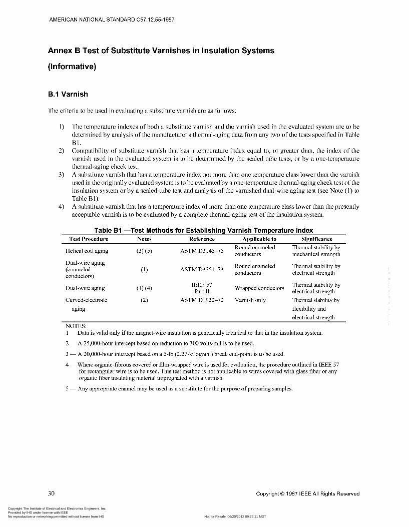
AMERICAN NATIONAL STANDARD C57.12.55-1987
Annex B Test of Substitute Varnishes in Insulation Systems
(Informative)
B.l Varnish
The criteria to be used in evaluating a substitute varnish are as follows:
1) The temperature indexes of both a substitute varnish and the varnish used in the evaluated system are to be determined by analysis of the manufacturer’s thermal-aging data from any two of the tests specified in Table B1. Compatibility of substitute varnish that has a temperature index equal to, or greater than, the index of the varnish used in the evaluated system is to be determined by the sealed tube tests, or by a one-temperature thermal-aging check test. A substitute varnish that has a temperature index not more than one temperature class lower than the varnish used in the originally evaluated system is to be evaluated by a one-temperature thermal-aging check test of the insulation system or by a sealed-tube test and analysis of the varnished dual-wire aging test (see Note (1) to Table B 1). A substitute varnish that has a temperature index of more than one temperature class lower than the presently acceptable varnish is to be evaluated by a complete thermal-aging test of the insulation system.
2)
3)
4)
Table B I -Test Methods for Establishing Varnish Temperature Index ‘I’c*t I>roucdurc Zote* I<cfcrcnuc ,\r>r>liuahlc to Signifiuanuc
Helical coil aging
Dual-wire aging (enameled conductors)
Dual-wire aging
(3) (5) Round enameled Thermal stability by
mechanical strength
Round enameled Thermal stability by
ASTM D3 145-75 conductors
ASTM D325 1-73 conductors electrical strength
Thermal stability by Wrapped conductors IEEE 57 Pari II electrical strength
Curved-electrode ASTM D1932-72 Varnish only Thermal stability by aging flexibility and
electrical strength NOTES: 1 ~ Data is valid only if the magnet-wire insulation is generically identical to that in the insulation system.
2 ~ A 25,000-hour intercept based on reduction to 300 volts/mil is to be used.
3 ~ A 20,000-hour intercept based on a 5-lb (2.27-kilogram) break end-point is to be used.
4 ~ Where organic-fibrous covered or film-wrapped wire is used for evaluation, the procedure outlined in IEEE 57 for rectangular wire is to be used. This test method is not applicable to wires covered with glass fiber or any organic fiber insulating material impregnated with a varnish.
5 ~ Any appropriate enamel may be used as a substitute for the purpose of preparing samples.
30 Copyright O 1987 IEEE All Rights Reserved
Copyright The Institute of Electrical and Electronics Engineers, Inc. Provided by IHS under license with IEEE Licensee=Fluor Corp no FPPPV per administrator /2110503106, User=chavez, franci
Not for Resale, 06/20/2012 09:23:11 MDTNo reproduction or networking permitted without license from IHS
--`,`````,``,,`,,`,,,,,,,`,`,,,-`-`,,`,,`,`,,`---
B.2 Magnet Wire
The criteria to be used in evaluating a substitute magnet-wire coating are as follows:
1)
2)
The class of the substitute film coating or combination of film coatings, determined in accordance with the requirements for Magnet Wire, ANSUNEMA MW1000-198 1, is to be the same as that originally used or The following conditions are to be met: a)
b)
The film coating or combination of film coating is generically similar to that used in the original system, as determined by either infrared analysis or comparative chemical description. The temperature rating of the magnet wire, as determined by Test for Relative Thermal Endurance of Film Insulated Round Magnet Wire, ASTM D2307-1973, or other suitable means, is at least equivalent to the temperature rating of magnet wire used in the original insulation system. The conductor material is the same, except that aluminum magnet wire may be substituted for copper magnet wire.
c)
B.3 Topcoat
The acceptability of a single-layer topcoat over an acceptable base coat is to be evaluated by the sealed-tube test or a single-temperature thermal-aging test.
B.4 Substitute Components
A substitute component other than those mentioned in Section B2 is to be evaluated by the full-thermal-aging program.
31 Copyright The Institute of Electrical and Electronics Engineers, Inc. Provided by IHS under license with IEEE Licensee=Fluor Corp no FPPPV per administrator /2110503106, User=chavez, franci
Not for Resale, 06/20/2012 09:23:11 MDTNo reproduction or networking permitted without license from IHS
--`,`````,``,,`,,`,,,,,,,`,`,,,-`-`,,`,,`,`,,`---